Problems of Forensic Sciences 2013, vol. 95, 651–669 GPS RECEIVERS AS SOURCES OF DIGITAL EVIDENCE Piotr Krzemień, Jan UNARSKI, radosław GRZEGORSKI Institute of Forensic Research, Kraków, Poland Abstract The authors discuss the possibility of making use of receivers with a GPS satellite navigation function as sources of evidence that are useful in road accident reconstruction. Many available navigation receivers enable recording of the so-called “track”, which is described by geographic co-ordinates of the vehicle’s position and velocity at given moments of time. The specifica- tions of various models (produced by various manufacturers) have been presented, together with the data recording mode and the method of saving data. The need to exercise caution in interpreting vehicle movement parameters read from a file contain- ing the track (route taken) and interpretation errors have been highlighted. APrS and other ways of track recording on internet servers have been briefly outlined. Key words GPS receiver; Satellite navigation; Track recording; Vehicle motion parameters; APRS; Investigation procedure. Received 6 December 2012; accepted 21 May 2013 1. Global Positioning System (GPS) GPS works on the basis of measuring the time radio signals from satellites take to reach a receiver. When the velocity of the electromagnetic wave and the pre- cise time of sending of the signals are known, the dis- tance between the receiver and satellites can be calcu- lated. GPS signals contain information on the positions of satellites as well as information on their theoretical trajectory and deviations from it. In the first phase, the GPS receiver updates the information in its memory, and next uses it to determine its geographic position (longitude and latitude as well as ellipsoidal altitude) and next presents it in a selected reference system. The standard reference system is WGS-84 – the World Geodetic System, which is a set of parameters defin- ing the dimensions and shape of the earth as well as its gravitational potential. The current GPS time is given with a very high accuracy according to UTC. The system operates throughout the world, because at least four satellites are always visible at each point of the globe. Satellites orbit the Earth at an altitude of about 20,183 km, which is lower than the geostationary orbit. Thanks to S/A (Selective Availability) – which interferes with information on satellite position – be- ing switched off, and atomic clock corrections (related with the relativity effect), the positioning accuracy for ordinary users has increased to about 4–12 m (initially it was about 100 m) [2]. 2. Road accidents In Poland, so-called accident data recorders have not been mounted in new vehicles so far, which is a standard practice in the United States. However, tach- ographs are required in certain types of trucks and also in vehicles used for transporting people commercially. Nevertheless, from the point of view of road accident

Welcome message from author
This document is posted to help you gain knowledge. Please leave a comment to let me know what you think about it! Share it to your friends and learn new things together.
Transcript
Problems of Forensic Sciences 2013, vol. 95, 651–669
GPS receiverS aS SourceS of diGital evidence
Piotr Krzemień, Jan Unarski, radosław GrzeGorski
Institute of Forensic Research, Kraków, Poland
abstractThe authors discuss the possibility of making use of receivers with a GPS satellite navigation function as sources of evidence that are useful in road accident reconstruction. Many available navigation receivers enable recording of the so-called “track”, which is described by geographic co-ordinates of the vehicle’s position and velocity at given moments of time. The specifica-tions of various models (produced by various manufacturers) have been presented, together with the data recording mode and the method of saving data. The need to exercise caution in interpreting vehicle movement parameters read from a file contain-ing the track (route taken) and interpretation errors have been highlighted. APrS and other ways of track recording on internet servers have been briefly outlined.
Key wordsGPs receiver; satellite navigation; Track recording; Vehicle motion parameters; aPrs; investigation procedure.
Received 6 December 2012; accepted 21 May 2013
1. Global Positioning System (GPS)
GPS works on the basis of measuring the time radio signals from satellites take to reach a receiver. When the velocity of the electromagnetic wave and the pre-cise time of sending of the signals are known, the dis-tance between the receiver and satellites can be calcu-lated. GPs signals contain information on the positions of satellites as well as information on their theoretical trajectory and deviations from it. in the first phase, the GPs receiver updates the information in its memory, and next uses it to determine its geographic position (longitude and latitude as well as ellipsoidal altitude) and next presents it in a selected reference system. The standard reference system is WGs-84 – the World Geodetic System, which is a set of parameters defin-ing the dimensions and shape of the earth as well as its gravitational potential. The current GPs time is given with a very high accuracy according to UTC.
The system operates throughout the world, because at least four satellites are always visible at each point of the globe. satellites orbit the earth at an altitude of about 20,183 km, which is lower than the geostationary orbit. Thanks to S/A (Selective Availability) – which interferes with information on satellite position – be-ing switched off, and atomic clock corrections (related with the relativity effect), the positioning accuracy for ordinary users has increased to about 4–12 m (initially it was about 100 m) [2].
2. road accidents
in Poland, so-called accident data recorders have not been mounted in new vehicles so far, which is a standard practice in the United States. However, tach-ographs are required in certain types of trucks and also in vehicles used for transporting people commercially. Nevertheless, from the point of view of road accident
P. Krzemień, J. Unarski, R. Grzegorski652
Problems of Forensic Sciences 2013, vol. 95, 651–669
reconstruction the parameters of recordings of these devices leave a lot to be desired [4]. it would seem that introduction of electronic tachographs would solve the problem; however, the potential of the current flash1 memory has not been exploited. nor has the require-ment of a recording frequency greater than once per second been made legally binding. in consequence, for instance, it is impossible to determine vehicle braking deceleration, on the basis of a tachograph recording, if the braking manoeuvre is short and intense. in prac-tice, it even happens that printouts from digital tacho-graphs filed in case files do not contain the time scale on successive magnifications. This necessitates the ap-plication of the rather imprecise procedure of scaling. Besides, tachographs do not record any data on vehi-cle location, which could be useful in identifying the route (track) of a vehicle whose driver, for example, has fled from the scene of an accident. an advantage of analogue tachographs – which are gradually being replaced by digital successors – is that the analysis of the recording and its disturbances stored on the tacho-graph disc allows reading of the vehicle’s velocity at the time at which the accident happened, which is not possible in the analysis of a digital record.
Moreover, the technological improvement of mate-rials used for vehicle manufacture together with ABS have resulted in less useful evidence left after a road accident (clean accident).
3. GPS data recording
The non-volatile memory of satellite mobile navi-gation systems is fast and allows recording of a large amount of data. Navigation software producers are introducing so-called “track recording” functions into the majority of these mini-computers. nMea 0183 sentences is a common recording standard, which documents various parameters, including the current position of the device (geographic longitude and lati-tude) as a function of time and velocity in mph and km/h [6]. A recording is made every 1 s, which is the same recording frequency as in digital tachographs, which does not make navigation devices better in this respect. What is an advantage is the extremely precise
1 eeProM (electrically-erasable Programmable read-only Memory) enables the recording or deleting of many memory cells during a single programming operation. it is non-vol-atile memory: there is no content loss if power is switched off. There are two types of flash memory: NOr and NAND, which differ in the type of iGate used in memory cells. The names of the memory types are derived from the type of iGate used.
GPS time and the possibility to retrieve the vehicle’s route (track). it is also possible to visualise the route in popular computer programs and internet services such as Google Maps or Google earth.
Several such devices were tested to check the use-fulness of the recorded information in road accident reconstruction. all the maps presented further on in the article are parts of a screen view from Google earth and have been published under fair-use. They were supplied by mGGP Aero.
4. tested devices
GPS navigation devices produced nowadays are equipped with efficient processors operating at a fre-quency of the order of 500 MHz, and high flash mem-ory capacity. an advantage of using semi-conductor memory is its overloading tolerance – overloading could cause mechanical damage to hard discs in the case of an accident. Track files stored in the memory of navigation devices take up very little space. For in-stance, the file of a route covered in ca. 25 min takes up ca. 640 kB, which means that the recording of a one hour route should not exceed 1.5 MB.
The tests were performed on the following devic-es:– Navroad 460BT with Automapa XL Polska navi-
gation program, version 6.2.0, 6.6.0 and navroad mapa 7.2, Windows Ce Core 5.0 operating sys-tem;
– Garmin Nuvi 255W, with GP mapa navigation pro-gram, Garmin os;
– Pentagram Nomad P 5220 with Automapa 6.1.0 navigation program, Windows Ce Core 5.0 operat-ing system;
– TomTom One iQ routes with TomTom navigation program, modified symbian operating system;
– Acer n35 with Automapa 6.3.0 program, Windows Mobile operating system;
– mio C720 with miomap program, Windows Ce Core 5.0 operating system;
– Samsung Omnia cell phone with Automapa 5.3.0 program, Windows mobile operating system;
– Sony ericsson XPeria 10 mini cell phone with eV speedo and My Tracks programs, android 2.1 up-date1 operating system.The place in the memory in which the track is re-
corded, the recording mode (optimised or not) and au-tomatic or other track recording differs between these devices. The default recording place is usually on the flash memory partition which contains the navigation program. it is impossible to install some navigation
GPS receivers as sources of digital evidence 653
Problems of Forensic Sciences 2013, vol. 95, 651–669
TABLe i. CHArACTeriSTiC FeATUreS OF reCOrDiNG mODe OF TeSTeD DeViCeS AND reCOrDiNG CONDiTiONS
Devicefeature / testing mode
Place of default recording
recording place option
Default recording / recording on request
standard (file extension) / recording optimisation
Testing mode – data acquisition from satellites during driving or statically
navroadDevice memory for Automapa / SD card for navroad
Yes on requestnMea (.auto, .auto.gps) / recording non-optimised – every 1s
Driving
Garmin Device memory no AlwaysGPX (.gdb, .mps) / frequency optimisation depending on route velocity and shape
Driving
Pentagram Device memory Yes on request nMea (.auto, .auto.gps) / non-optimised – recording every 1s Driving
TomTomDevice memory – only system files, no decoding possible
no recording option
no recording option ? (.dat, .iti) / no information Driving
acer Device memory Yes on request nMea (.auto, .auto.gps) / non-
optimised- recording every 1s Driving
Mio Device memory Yes on request nMea (.auto, .auto.gps) / non-
optimised – recording every 1s statically
samsung omnia
Device memory Yes on request nMea (.auto, .auto.gps) / non-
optimised- recording every 1s statically
sony ericsson SD card no on request nMea (.kml) / optional Driving
programs on just any memory partition. This is be-cause there are regions from which all data are deleted after the so-called hard restart, so program producers prevent installation of their navigation programs on such regions of flash memory. in some devices, how-ever, it is possible to change the recording place. The differences between devices and testing mode have been presented in Table i.
5. comparison of recorded tracks
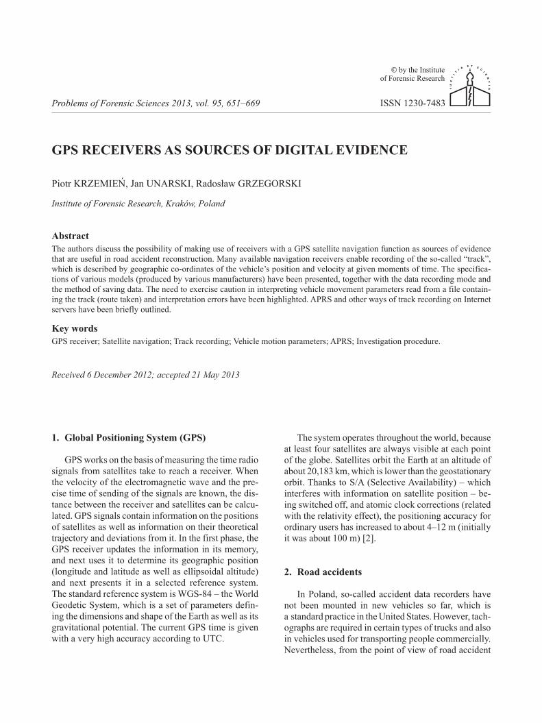
The route covered was defined very strictly. During the runs, several devices were switched on at the same time, which enabled a comparison of the recorded in-formation. each run consisted in driving along a road circuit in Kraków two times. During the first circuit, the track recording option was off, during the second one, the option was on in the devices supporting it. A view of the route covered is shown in Figure 1.
Fig. 1. Test route. To identify the tested devices, particular tracks are denoted by colours: pink – Pentagram automapa, crim-son – Acer Automapa, brown – Navroad Automapa, blue – Garmin GP mapa.
P. Krzemień, J. Unarski, R. Grzegorski654
Problems of Forensic Sciences 2013, vol. 95, 651–669
5.1. steady-state driving along the route
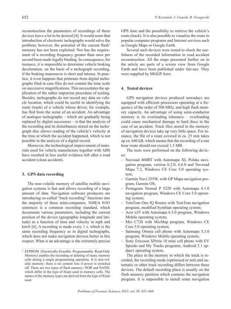
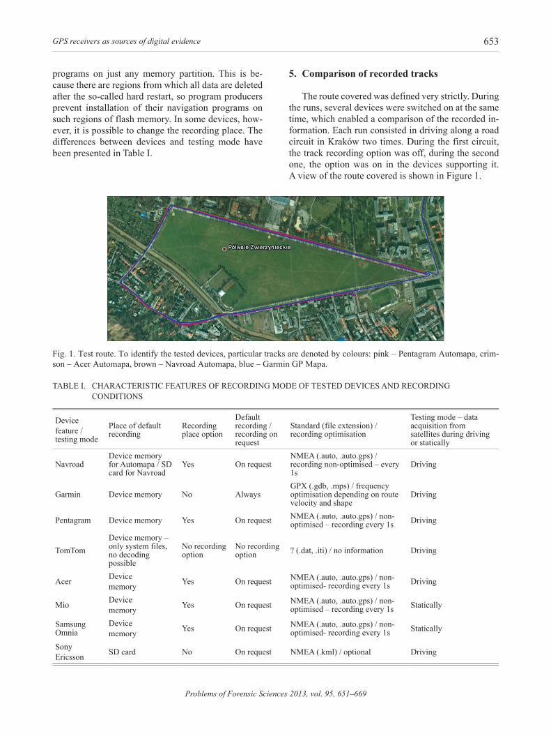
speeds recorded at the same time and at the same place on the route were compared. They are presented in Figures 2, 3, 4 and 5.
Fig. 2. Parameters from Pentagram.
Fig. 3. Parameters from acer.
Fig. 4. Parameters from navroad.
Fig. 5. Parameters from Garmin.
The comparison shows that the speeds ranged from 48.4 to 53.4 km/h, altitudes from 195.2 to 245 m above sea level, and headings on a selected section from 281.4° to 286.9°. Differences were also observed in the geographic position calculated by particular re-ceivers. it is noticeable that the tracks do not coincide with the road, so the accuracy of the given position is insufficient to determine, for instance, a place of col-lision, or a place where the driver performed certain manoeuvres. The accuracy of the geographic position calculated by the receivers is difficult to estimate since the geographic positions given by internet portals are also undoubtedly burdened with some error.
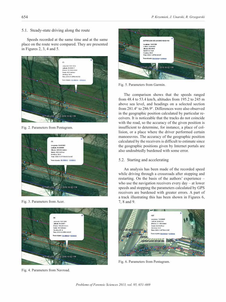
5.2. starting and accelerating
an analysis has been made of the recorded speed while driving through a crossroads after stopping and restarting. On the basis of the authors’ experience – who use the navigation receivers every day – at lower speeds and stopping the parameters calculated by GPs receivers are burdened with greater errors. A part of a track illustrating this has been shown in Figures 6, 7, 8 and 9.
Fig. 6. Parameters from Pentagram.

GPS receivers as sources of digital evidence 655
Problems of Forensic Sciences 2013, vol. 95, 651–669
Fig. 7. Parameters from acer.
Fig. 8. Parameters from navroad.
Fig. 9. Parameters from Garmin.
An analysis of the data shows that the recorded speed ranged from 12.6 to 22.4 km/h, altitude from 194.8 to 241.6 m above sea level, and heading from 260.8° to 283.6°. The authors’ previous assumptions that at lower driving speeds and acceleration, the dif-ferences in recorded speed can be as high as 100% have been confirmed. also the differences in the re-corded heading and altitude have increased. a similar observation can be made for the vehicle position on the roadway: the car did not drive onto the no-traffic part of the roadway, as suggested by two recordings.
5.3. stopping the vehicle
A situation of driving into a parking lot and switch-ing off the devices is shown in Figures 10, 11, 12 and 13.
Fig. 10. Parameters from Pentagram.
Fig. 11. Parameters from acer.
Fig. 12. Parameters from navroad.

P. Krzemień, J. Unarski, R. Grzegorski656
Problems of Forensic Sciences 2013, vol. 95, 651–669
Fig. 13. Parameters from Garmin.
From a comparison of the above data, it transpires that despite the fact that the car had been immobile for a few seconds, the devices indicated a speed different from zero (except Garmin which did not indicate any speed at all, and indicated the heading to be zero). The speed ranged from 15.1 m/h to 8.6 km/h, altitude from 191.4 to 244.8 m above sea level, and the heading from 65.6° to 85.5°. These records together with the differ-ences in the last recorded geographic position confirm the unsuitability of the recording in the determination of parameters of slow driving or a stationary position. The only thing we can try to determine is the stopping period if many points of the track overlap (see Figures 10 and 12).
5.4. interference and errors
An analysis of the recorded data showed that gross errors may occur in the transmitted values. Therefore, caution must be exercised in respect to the recorded data: they must always be analysed over a longer road section. examples of incorrect indications have been shown in Figures 14 and 15.
Fig. 14. Parameters from Garmin – incorrect record.
The speed indicated by the other devices ranged from 22.6 to 28.5 km/h, whereas Garmin indicated a speed of 55.4 km/h. it is a speed that is impossible to reach in the conditions in which the experiment was run.
Fig. 15. Parameters from Garmin – incorrect record.
as mentioned in the paragraph on data recording mode, Garmin always recorded the optimised track. While driving to the place of the experiment, when the recording function was off in the other receivers, the only track recorded was that by Garmin. The record-ing indicated that the vehicle was moving at a speed of about 126 km/h, which was not consistent with the actual speed. although the actual speed cannot be given, it should be stated that due to the speed limit and heavy traffic the speed did not exceed 60 km/h, while the next recording from this device, 14 s later, indicated a speed of about 43 km/h.
5.5. Braking tests
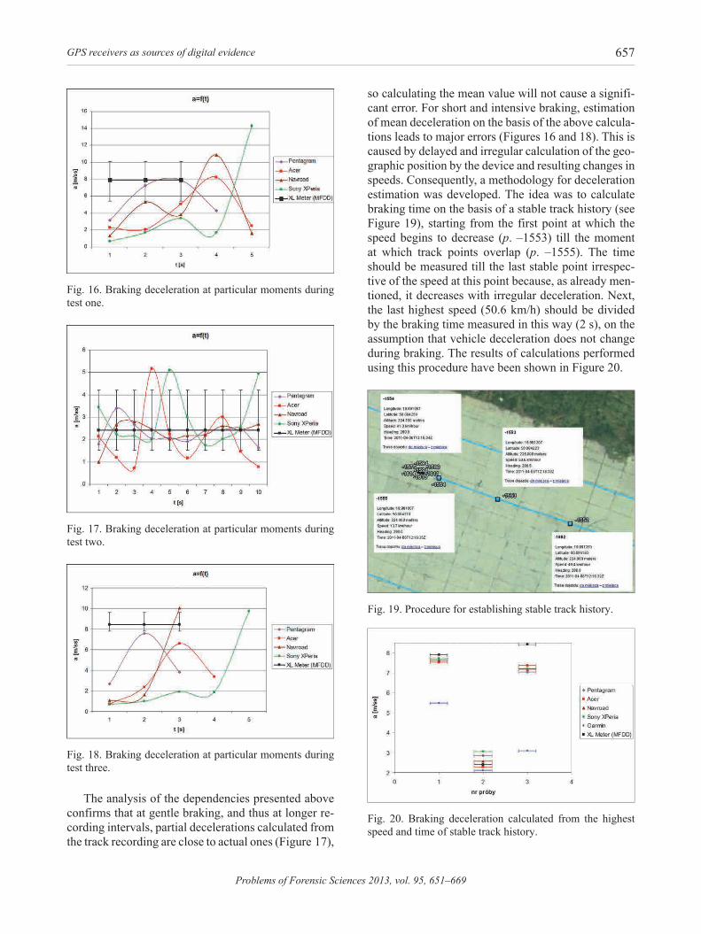
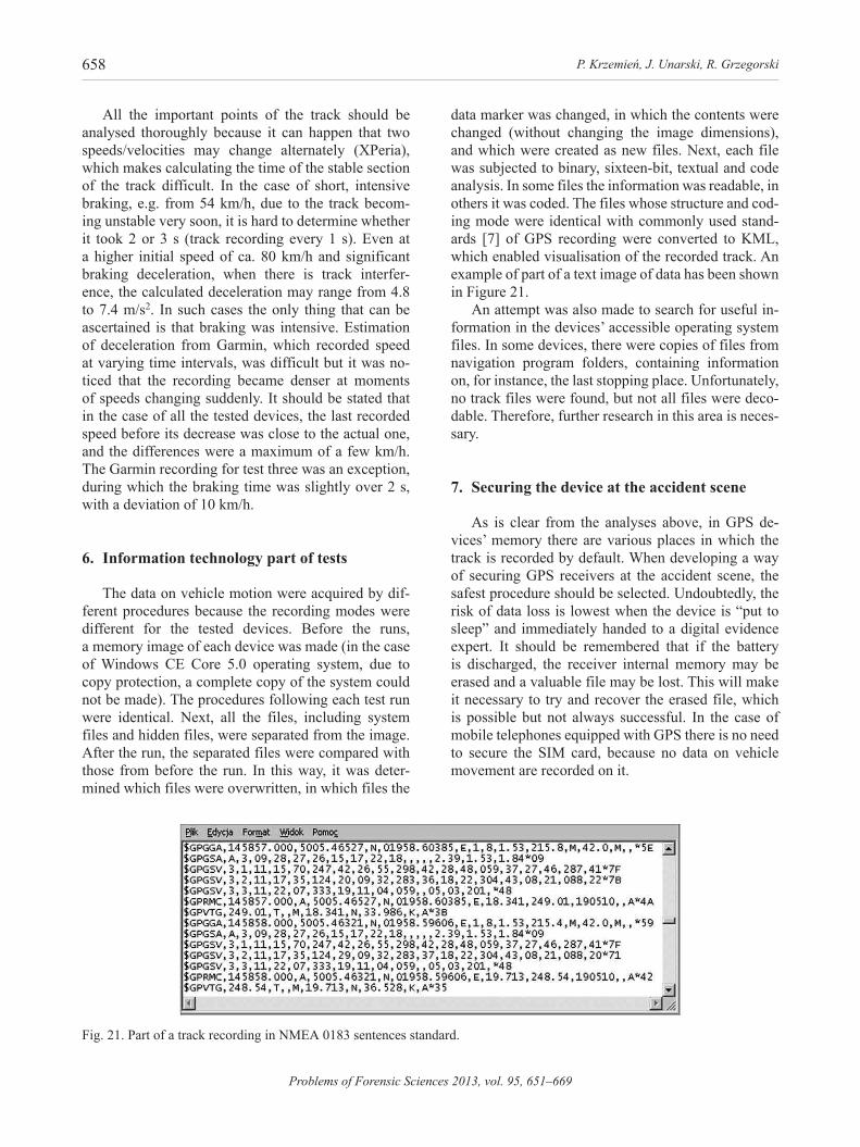
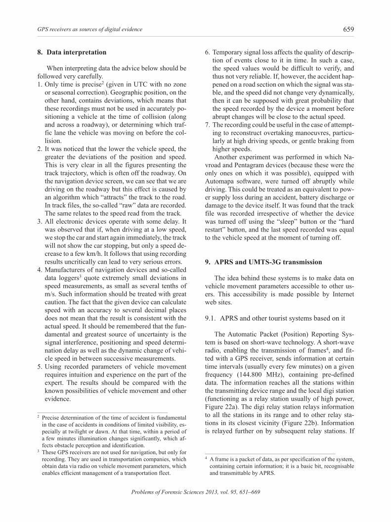
From the performed analyses it follows that the in-dication accuracy of the tested devices increases with the driving speed and motion stability. To check the dependence between the real averaged braking decel-eration (mFDD) and the deceleration calculated from the track recording, braking tests were performed with a car equipped with an XL meter. in the first test the car braked suddenly, from a speed of ca. 86 km/h with a deceleration of 7.9 m/s2 in 3.4 s time. in the next test, the braking was gentle from a speed of ca. 87 km/h, with a deceleration of 2.4 m/s2 in 9.6 s time. in the final test the car braked from a speed of ca. 54 km/h, with a deceleration of 8.4 m/s2 in 2.1 s time. next, the speed decrease was calculated at particular points of the track at a particular time, which resulted in car decelerations (ai = ΔVi/Δti) at particular braking stages, which has been illustrated in Figures 16, 17 and 18.
GPS receivers as sources of digital evidence 657
Problems of Forensic Sciences 2013, vol. 95, 651–669
Fig. 16. Braking deceleration at particular moments during test one.
Fig. 17. Braking deceleration at particular moments during test two.
Fig. 18. Braking deceleration at particular moments during test three.
The analysis of the dependencies presented above confirms that at gentle braking, and thus at longer re-cording intervals, partial decelerations calculated from the track recording are close to actual ones (Figure 17),
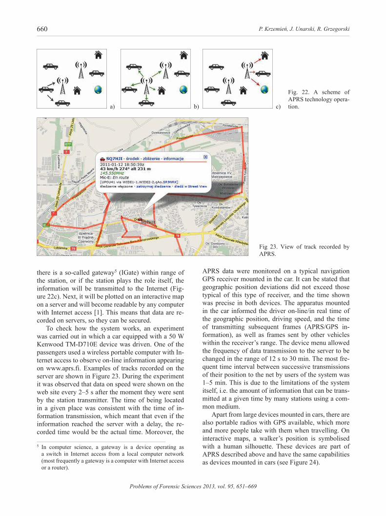
so calculating the mean value will not cause a signifi-cant error. For short and intensive braking, estimation of mean deceleration on the basis of the above calcula-tions leads to major errors (Figures 16 and 18). This is caused by delayed and irregular calculation of the geo-graphic position by the device and resulting changes in speeds. Consequently, a methodology for deceleration estimation was developed. The idea was to calculate braking time on the basis of a stable track history (see Figure 19), starting from the first point at which the speed begins to decrease (p. –1553) till the moment at which track points overlap (p. –1555). The time should be measured till the last stable point irrespec-tive of the speed at this point because, as already men-tioned, it decreases with irregular deceleration. Next, the last highest speed (50.6 km/h) should be divided by the braking time measured in this way (2 s), on the assumption that vehicle deceleration does not change during braking. The results of calculations performed using this procedure have been shown in Figure 20.
Fig. 19. Procedure for establishing stable track history.
Fig. 20. Braking deceleration calculated from the highest speed and time of stable track history.
P. Krzemień, J. Unarski, R. Grzegorski658
Problems of Forensic Sciences 2013, vol. 95, 651–669
all the important points of the track should be analysed thoroughly because it can happen that two speeds/velocities may change alternately (XPeria), which makes calculating the time of the stable section of the track difficult. in the case of short, intensive braking, e.g. from 54 km/h, due to the track becom-ing unstable very soon, it is hard to determine whether it took 2 or 3 s (track recording every 1 s). even at a higher initial speed of ca. 80 km/h and significant braking deceleration, when there is track interfer-ence, the calculated deceleration may range from 4.8 to 7.4 m/s2. in such cases the only thing that can be ascertained is that braking was intensive. estimation of deceleration from Garmin, which recorded speed at varying time intervals, was difficult but it was no-ticed that the recording became denser at moments of speeds changing suddenly. it should be stated that in the case of all the tested devices, the last recorded speed before its decrease was close to the actual one, and the differences were a maximum of a few km/h. The Garmin recording for test three was an exception, during which the braking time was slightly over 2 s, with a deviation of 10 km/h.
6. information technology part of tests
The data on vehicle motion were acquired by dif-ferent procedures because the recording modes were different for the tested devices. Before the runs, a memory image of each device was made (in the case of Windows Ce Core 5.0 operating system, due to copy protection, a complete copy of the system could not be made). The procedures following each test run were identical. Next, all the files, including system files and hidden files, were separated from the image. After the run, the separated files were compared with those from before the run. in this way, it was deter-mined which files were overwritten, in which files the
data marker was changed, in which the contents were changed (without changing the image dimensions), and which were created as new files. Next, each file was subjected to binary, sixteen-bit, textual and code analysis. in some files the information was readable, in others it was coded. The files whose structure and cod-ing mode were identical with commonly used stand-ards [7] of GPS recording were converted to KmL, which enabled visualisation of the recorded track. An example of part of a text image of data has been shown in Figure 21.
An attempt was also made to search for useful in-formation in the devices’ accessible operating system files. in some devices, there were copies of files from navigation program folders, containing information on, for instance, the last stopping place. Unfortunately, no track files were found, but not all files were deco-dable. Therefore, further research in this area is neces-sary.
7. Securing the device at the accident scene
as is clear from the analyses above, in GPs de-vices’ memory there are various places in which the track is recorded by default. When developing a way of securing GPs receivers at the accident scene, the safest procedure should be selected. Undoubtedly, the risk of data loss is lowest when the device is “put to sleep” and immediately handed to a digital evidence expert. it should be remembered that if the battery is discharged, the receiver internal memory may be erased and a valuable file may be lost. This will make it necessary to try and recover the erased file, which is possible but not always successful. in the case of mobile telephones equipped with GPS there is no need to secure the siM card, because no data on vehicle movement are recorded on it.
Fig. 21. Part of a track recording in nMea 0183 sentences standard.
GPS receivers as sources of digital evidence 659
Problems of Forensic Sciences 2013, vol. 95, 651–669
8. data interpretation
When interpreting data the advice below should be followed very carefully.1. only time is precise2 (given in UTC with no zone
or seasonal correction). Geographic position, on the other hand, contains deviations, which means that these recordings must not be used in accurately po-sitioning a vehicle at the time of collision (along and across a roadway), or determining which traf-fic lane the vehicle was moving on before the col-lision.
2. it was noticed that the lower the vehicle speed, the greater the deviations of the position and speed. This is very clear in all the figures presenting the track trajectory, which is often off the roadway. On the navigation device screen, we can see that we are driving on the roadway but this effect is caused by an algorithm which “attracts” the track to the road. in track files, the so-called “raw” data are recorded. The same relates to the speed read from the track.
3. All electronic devices operate with some delay. it was observed that if, when driving at a low speed, we stop the car and start again immediately, the track will not show the car stopping, but only a speed de-crease to a few km/h. it follows that using recording results uncritically can lead to very serious errors.
4. Manufacturers of navigation devices and so-called data loggers3 quote extremely small deviations in speed measurements, as small as several tenths of m/s. Such information should be treated with great caution. The fact that the given device can calculate speed with an accuracy to several decimal places does not mean that the result is consistent with the actual speed. it should be remembered that the fun-damental and greatest source of uncertainty is the signal interference, positioning and speed determi-nation delay as well as the dynamic change of vehi-cle speed in between successive measurements.
5. Using recorded parameters of vehicle movement requires intuition and experience on the part of the expert. The results should be compared with the known possibilities of vehicle movement and other evidence.
2 Precise determination of the time of accident is fundamental in the case of accidents in conditions of limited visibility, es-pecially at twilight or dawn. At that time, within a period of a few minutes illumination changes significantly, which af-fects obstacle perception and identification.
3 These GPs receivers are not used for navigation, but only for recording. They are used in transportation companies, which obtain data via radio on vehicle movement parameters, which enables efficient management of a transportation fleet.
6. Temporary signal loss affects the quality of descrip-tion of events close to it in time. in such a case, the speed values would be difficult to verify, and thus not very reliable. if, however, the accident hap-pened on a road section on which the signal was sta-ble, and the speed did not change very dynamically, then it can be supposed with great probability that the speed recorded by the device a moment before abrupt changes will be close to the actual speed.
7. The recording could be useful in the case of attempt-ing to reconstruct overtaking manoeuvres, particu-larly at high driving speeds, or gentle braking from higher speeds. Another experiment was performed in which Na-
vroad and Pentagram devices (because these were the only ones on which it was possible), equipped with Automapa software, were turned off abruptly while driving. This could be treated as an equivalent to pow-er supply loss during an accident, battery discharge or damage to the device itself. it was found that the track file was recorded irrespective of whether the device was turned off using the “sleep” button or the “hard restart” button, and the last speed recorded was equal to the vehicle speed at the moment of turning off.
9. aPrS and uMtS-3G transmission
The idea behind these systems is to make data on vehicle movement parameters accessible to other us-ers. This accessibility is made possible by internet web sites.
9.1. aPrs and other tourist systems based on it
The automatic Packet (Position) reporting sys-tem is based on short-wave technology. A short-wave radio, enabling the transmission of frames4, and fit-ted with a GPS receiver, sends information at certain time intervals (usually every few minutes) on a given frequency (144.800 MHz), containing pre-defined data. The information reaches all the stations within the transmitting device range and the local digi station (functioning as a relay station usually of high power, Figure 22a). The digi relay station relays information to all the stations in its range and to other relay sta-tions in its closest vicinity (Figure 22b). information is relayed further on by subsequent relay stations. if
4 a frame is a packet of data, as per specification of the system, containing certain information; it is a basic bit, recognisable and transmittable by aPrs.
P. Krzemień, J. Unarski, R. Grzegorski660
Problems of Forensic Sciences 2013, vol. 95, 651–669
there is a so-called gateway5 (iGate) within range of the station, or if the station plays the role itself, the information will be transmitted to the internet (Fig-ure 22c). Next, it will be plotted on an interactive map on a server and will become readable by any computer with internet access [1]. This means that data are re-corded on servers, so they can be secured.
To check how the system works, an experiment was carried out in which a car equipped with a 50 W Kenwood Tm-D710e device was driven. One of the passengers used a wireless portable computer with in-ternet access to observe on-line information appearing on www.aprs.fi. examples of tracks recorded on the server are shown in Figure 23. During the experiment it was observed that data on speed were shown on the web site every 2–5 s after the moment they were sent by the station transmitter. The time of being located in a given place was consistent with the time of in-formation transmission, which meant that even if the information reached the server with a delay, the re-corded time would be the actual time. moreover, the
5 in computer science, a gateway is a device operating as a switch in internet access from a local computer network (most frequently a gateway is a computer with internet access or a router).
APrS data were monitored on a typical navigation GPs receiver mounted in the car. it can be stated that geographic position deviations did not exceed those typical of this type of receiver, and the time shown was precise in both devices. The apparatus mounted in the car informed the driver on-line/in real time of the geographic position, driving speed, and the time of transmitting subsequent frames (aPrs/GPs in-formation), as well as frames sent by other vehicles within the receiver’s range. The device menu allowed the frequency of data transmission to the server to be changed in the range of 12 s to 30 min. The most fre-quent time interval between successive transmissions of their position to the net by users of the system was 1–5 min. This is due to the limitations of the system itself, i.e. the amount of information that can be trans-mitted at a given time by many stations using a com-mon medium.
apart from large devices mounted in cars, there are also portable radios with GPS available, which more and more people take with them when travelling. On interactive maps, a walker’s position is symbolised with a human silhouette. These devices are part of aPrs described above and have the same capabilities as devices mounted in cars (see Figure 24).
a) b) c)
Fig. 22. a scheme of aPrs technology opera-tion.
Fig 23. View of track recorded by aPrs.

GPS receivers as sources of digital evidence 661
Problems of Forensic Sciences 2013, vol. 95, 651–669
as can be seen, the shape of the devices resem-bles that of short-wave transmitters or multi-function watches; they do not look like navigation devices that record and transmit data that are so useful for judicial bodies. it should also be remembered that in the case of APrS due to the low frequency of data transmis-sion, the track is visualised by joining points at quite a distance from one another by a broken line. such a track recording often deviates significantly from the real curvature of the road, which, however, does not mean that the receiver and its user were taking a short cut, although it does not rule it out in the case of a walker or a cyclist, for instance.
The most interesting aspect of these systems is the possibility of recording, reconstructing, presenting and editing the route (track) on the computer screen as well as the possibility of marking additional ele-ments along the route during your wandering. Finding such a device during a search for a missing person, for example, may help to reconstruct the route along which s/he was travelling, where s/he stopped for rest or what alternative routes s/he recorded for the way back, which can turn out to be an invaluable help in finding him/her.
Frames can also be transmitted from mobile tele-phones to aPrs by data transmission made accessible by the cell phone operator, which is similar to the data transmission system described in the next section of the article. The information sent to the server enables the read-out of parameters such as:– name / call sign / login of the user (e.g. sQ7HJi);– date and time (2011.01.12, 18:50);– transmitting station speed (43 km/h);– altitude above sea level (231 m);– geographic position (map);– additional information, e.g. vehicle registration
number (if the user enters it), vehicle make, route history from the previous day;
– information about system users sending data to the server around the same time.
9.2. GPS with GSm, UmTS and 3G transmission
Data can be transmitted by mobile telephones, sat-ellite navigation systems with GSm module or satel-lite navigation systems connected to GsM telephone. one of the internet services enabling a user to present on-line data on his movement to other users of the data service is www.miplo.pl. The track preview is very similar to the APrS view, as is the information transmitted.
since in the presented systems, information is transmitted at a frequency (of the order) of once every few minutes, whereas for the needs of accident recon-struction, data should be transmitted at least every sec-ond, this system is of little use in this field. However, it can be used in the following cases:– if information on the vehicle route prior to the ac-
cident is needed;– if the presence of a person or a car in a given place
needs to be confirmed or negated;– during search for missing persons who use this sys-
tem;– in searching for witnesses of accidents or other
crimes.During post-accident inspection or on being noti-
fied of a missing person, it is necessary to obtain infor-mation as to whether the user used any of the described systems. if they did, it is probable that the data we are searching for was recorded. The data recorded on the servers should be retrieved as soon after the event as possible because otherwise they can be overwritten by new data sent by other users of the system. it should also be remembered that identification data on inter-net sites are given by users, so they may not be real. in the case of transmission through a mobile phone operator, examination of billing can be helpful. How-ever, in the case of aPrs, the login can be changed in any of the devices. This could make it difficult to ascertain whether it was the particular user that used his/her call sign at the time in question, or whether somebody else did it by means of a completely dif-ferent transmitter fitted in a different car. The authors also know of a case of simulating or emulating a GPS signal in APrS devices, which can be an additional difficulty in interpretation of information on transmit-ter movement.
Fig. 24. examples of aPrs navigation devices used by tourists.
P. Krzemień, J. Unarski, R. Grzegorski662
Problems of Forensic Sciences 2013, vol. 95, 651–669
10. Summary
1. GPS based navigation devices can be fitted with an option of recording vehicle movement parameters. These parameters can be auto-recorded or recorded by the user by switching on the recording option.
2. in view of the tendency of manufacturers to fit navi-gation devices with functions for recording data on movement, it is advisable to secure these devices at road accident scenes, since the obtained data can be useful in road accident reconstruction, determina-tion of transportation routes of cargo and people, searching for missing persons, etc.
3. Data should be retrieved by a digital evidence ex-pert, who should receive the navigation device in the shortest possible time, having first switched it off with the “sleep” button – power, not the on-off switch, because it can cause resetting of the device memory.
4. The data obtained from the device should be inter-preted only by an expert in road accident analysis because the uncertainty of some indications may lead to serious errors in establishing the actual ac-cident course.
5. in the analysis of data obtained from a device, time corrections connected with zones and result-ing from summer and winter time should always be considered. in Poland, in the summer the devices record the time two hours earlier than the actual time, while in the winter the time recorded in the file is one hour earlier.
references
1. Grzegorski r., Krzemień P., Systemy rejestracji i prze-kazywania danych GPS, Paragraf na Drodze 2011, 6, 57–69.
2. http://www.gps.gov/ [03.2011 r.]. 3. Januszewski J., Systemy satelitarne GPS, Galileo i inne,
PWN, Warszawa 2006. 4. Krzemień P., Wykorzystanie możliwości rejestracyjnych
odbiorników GPS w rekonstrukcji wypadków drogo-wych, Paragraf na Drodze 2010, 10, 59–72.
5. Krzemień P., Unarski J., Wykorzystanie możliwości re-jestracyjnych odbiorników GPS w rekonstrukcji wypad-ków drogowych (kontynuacja badań), Paragraf na Dro-dze 2011, Xii Konferencja PrWD, 219–239.
6. Laboratorium Systemów mobilnych, Stworzenie modułu do parsowania danych z odbiornika GPS w standardzie NmeA – 0183 [http://mediawiki.ilab.pl/images/3/34/Sy-stemy_mobilne_laboratorium_8.pdf (9.2010 r.)].
7. Narkiewicz J., GPS i inne systemy satelitarne, WKiŁ, Warszawa 2007.
corresponding authorPiotr KrzemieńPracownia Badania Wypadków Drogowych ieSul. Polanki 122PL 80-308 Gdańske-mail: [email protected]
8. Unarski J., Krzemień P., making use of the recording ca-pabilities of GPs receivers in road accident reconstruc-tion, Proceedings 20th eVU annual Meeting, Graz Uni-versity of Technology, Graz 2011.
Problems of Forensic Sciences 2013, vol. 95, 651–669
1. Global Positioning System (GPS)
System GPS mierzy czas dotarcia sygnału radiowego z satelitów do odbiornika. Na podstawie prędkości fali elektromagnetycznej oraz dokładnego czasu wysłania danego sygnału, oblicza on odległość odbiornika od sa-telitów. Sygnał GPS zawiera w sobie informację o ukła-dzie satelitów oraz informację o ich teoretycznej trajek-torii i odchyleń od niej. Odbiornik GPS w pierwszej fazie aktualizuje te informacje w swojej pamięci oraz wyko-rzystuje je w dalszej części do ustalenia swojej pozycji geograficznej (długość i szerokość geograficzna oraz wysokość elipsoidalna) i następnie podaje ją w wybra-nym układzie odniesienia. Standardowo jest to WGS-84 (World Geodetic System) – zbiór parametrów określają-cych wielkość i kształt ziemi oraz właściwości jej poten-cjału grawitacyjnego. Aktualny czas GPS podawany jest z bardzo dużą dokładnością według czasu UTC.
System pracuje na obszarze całej ziemi, bo w każ-dym punkcie globu widoczne są zawsze przynajmniej cztery satelity. Satelity krążą po orbitach niższych niż geostacjonarna na wysokości około 20 183 km. Dzięki wyłączeniu mechanizmu S/A (Selective Availability) za-kłócającego informacje o położeniu satelity i poprawki zegarów atomowych (związane z efektem relatywistycz-nym), dokładność określania pozycji dla zwykłych użyt-kowników wzrosła do około 4–12 m (początkowo wyno-siła około 100 m) [2].
2. Wypadek drogowy
W Polsce dotychczas nie montuje się w nowych po-jazdach tzw. rejestratorów danych wypadkowych, co jest praktykowane np. w Stanach zjednoczonych. istnieje co prawda wymóg stosowania tachografów w określo-nych pojazdach ciężarowych i wykorzystywanych do świadczenia usług przewozu osób, jednak z punktu wi-dzenia rekonstrukcji wypadków drogowych parametry zapisu tych urządzeń pozostawiają wiele do życzenia [4, 5]. Wydawałoby się, że wprowadzenie tachografów elektronicznych rozwiąże ten problem, jednak nie sko-rzystano z możliwości, jakie dają obecne pamięci flash1
1 Jest to rodzaj pamięci eePrOm (electrically-erasable Pro-grammable read-Only memory) pozwalającej na zapisywa-nie lub kasowanie wielu komórek pamięci podczas jednej operacji programowania. Jest to pamięć stała (nieulotna), po odłączeniu zasilania nie traci swej zawartości. istnieją dwa rodzaje pamięci flash: NOr i NAND różniące się ty-pem bramki logicznej zastosowanej w komórkach pamięci. Nazwy rodzajów pamięci pochodzą od użytego typu bramki logicznej.
i nie zwiększono w sposób ustawowy wymogu zapisu z częstością większą niż 1 s. Powoduje to np. brak moż-liwości ustalenia na podstawie zapisu tachografu opóź-nienia hamowania pojazdu, jeśli hamowanie trwa krótko i jest intensywne. W praktyce zdarza się nawet, iż wy-druki z tachografów cyfrowych, znajdujące się w aktach sprawy, nie zawierają skali czasu na kolejnych powięk-szeniach. Powoduje to konieczność stosowania mało dokładnej procedury skalowania. Poza tym tachografy nie rejestrują żadnych danych dotyczących usytuowania pojazdu w terenie, co mogłoby być przydatne w ustaleniu trasy pojazdu, którego kierowca np. zbiegł z miejsca wy-padku. Tachografy analogowe, sukcesywnie wypierane przez ich cyfrowych następców mają tę zaletę, że analiza zapisu i jego zakłóceń na tarczy tachografu pozwalała na odczyt prędkości, przy której doszło do zderzenia po-jazdów, czego nie umożliwia analiza zapisu cyfrowego. Także technologiczny rozwój materiałów użytych do budowy pojazdów oraz systemy ABS spowodowały, że po wypadkach drogowych pozostaje coraz mniej przy-datnych śladów (ang. clean accident).
3. rejestracja danych GPS
Pamięci trwałe mobilnych urządzeń GPS są szybkie i pozwalają na zapis dużej liczby danych. Do większo-ści tych minikomputerów producenci oprogramowania nawigacyjnego wprowadzają funkcje tzw. zapisu śladu. Powszechnym standardem zapisu jest NmeA 0183 sen-tences, który dokumentuje m.in. poszczególne położenia urządzenia (długość i szerokość geograficzną) w funkcji czasu oraz prędkość w mph i km/h [6]. zapis dokonywa-ny jest co 1 s. Jest to zatem taka sama częstotliwość zapi-su, jak w tachografach cyfrowych, co nie czyni urządzeń nawigacyjnych lepszymi pod tym względem. zaletą jest niezwykle precyzyjnie podawany czas GPS oraz możli-wość odtworzenia trasy przejazdu. możliwa jest także wizualizacja trasy w popularnych programach kompute-rowych i serwisach internetowych, np. Google maps czy Google earth.
Przebadano kilka takich urządzeń w celu sprawdzenia przydatności zapisywanych informacji do rekonstrukcji wypadków drogowych. Wszystkie mapy przedstawione w dalszej części artykułu są fragmentami widoku ekra-nu z programu Google earth i zostały opublikowane na zasadach uczciwego wykorzystania (ang. fair-use). Do-stawcą map była firma mGGP Aero.
OdbiOrniki GPS jakO źródła śladów cyfrOwych

P. Krzemień, J. Unarski, R. Grzegorski664
Problems of Forensic Sciences 2013, vol. 95, 651–669
4. Przebadane urządzenia
Obecnie produkowane urządzenia nawigacyjne GPS są wyposażone w wydajne procesory pracujące z często-tliwością rzędu 500 mHz oraz dużą pojemność pamięci wewnętrznej typu flash. zaletą zastosowania pamięci półprzewodnikowej jest jej odporność na przeciążenia, które w razie wypadku mogłyby zniszczyć mechaniczne dyski twarde. Pliki śladów trasy zapisywane w pamię-ci urządzeń nawigacyjnych zajmują bardzo mało miej-sca. Przykładowo plik śladu trasy przejechanej w czasie ok. 25 min zajmuje ok. 640 kB, co oznacza, że zapis 1 h trasy nie powinien przekroczyć 1,5 mB. Przebadano na-stępujące urządzenia:– Navroad 460BT z oprogramowaniem nawigacyjnym
Automapa XL Polska w wersji 6.2.0, 6.6.0 i Navroad mapa 7.2, systemem operacyjnym Windows Ce Core 5.0;
– Garmin Nuvi 255 W z oprogramowaniem nawigacyj-nym GP Mapa i systemem operacyjnym Garmin os;
– Pentagram Nomad P 5220 z oprogramowaniem nawi-gacyjnym automapa 6.1.0 i systemem operacyjnym Windows Ce Core 5.0;
– TomTom One iQ routers z oprogramowaniem na-wigacyjnym TomTom i zmodyfikowanym systemem operacyjnym symbian;
– Acer n35 z oprogramowaniem Automapa 6.3.0 i sy-stemem operacyjnym Windows mobile;
– mio C720 z oprogramowaniem miomap i systemem operacyjnym Windows Ce Core 5.0;
– telefon komórkowy Samsung Omnia z oprogramowa-niem automapa 5.3.0 i systemem operacyjnym Win-dows mobile;
– telefon komórkowy Sony ericsson XPeria 10 mini z oprogramowaniem eV Speedo oraz my Tracks i z sy-stemem operacyjnym android 2.1 update1.Urządzenia te różnią się między sobą miejscem w pa-
mięci, w którym zapisywany jest ślad trasy, sposobem zapisu (optymalizowany lub nie) i automatycznym lub nie zapisem śladu. Domyślne miejsce zapisu znajduje się najczęściej na partycji pamięci flash, na której umiesz-czono oprogramowanie nawigacyjne. Niektóre oprogra-mowania nawigacyjne nie pozwalają na ich instalację na dowolnej partycji pamięci. istnieją bowiem obszary, z których usuwane są wszystkie dane po tzw. twardym restarcie, dlatego też producenci oprogramowania unie-możliwiają instalowanie swoich programów nawigacyj-nych na takich obszarach pamięci flash. W niektórych urządzeniach miejsce zapisu można jednak zmieniać do-wolnie. zróżnicowanie urządzeń i sposób badania przed-stawiono w tabeli i.
5. Porównanie zapisanych śladów
Wykonano przejazdy ściśle zdefiniowaną trasą z jed-nocześnie włączonymi kilkoma urządzeniami, co umoż-liwiło dokonanie porównania zapisanych informacji. Przejazd polegał na dwukrotnym okrążeniu pętli dro-gowej w Krakowie. Pierwsze okrążenie wykonano bez włączania opcji rejestracji śladu trasy, drugie natomiast po jej włączeniu w urządzeniach, w których taka opcja istniała. Widok przejechanej trasy przedstawia rycina 1.
W celu identyfikacji badanych urządzeń poszczegól-ne ślady oznaczono kolorami: różowy – Pentagram Au-tomapa, bordowy – Acer Automapa, brązowy – Navroad automapa, niebieski – Garmin GP Mapa.
5.1. Jazda ze stałą prędkością
Porównano prędkości w jednakowym czasie w tym samym miejscu trasy. Przedstawiono to na rycinach 2, 3, 4 i 5.
z powyższego porównania wynika, że wskazania prę-dkości zawierają się w granicach od 48,4 do 53,4 km/h, wskazania wysokości od 195,2 do 245 m n.p.m., a wska-zania kierunku jazdy na wybranym odcinku od 281,4 do 286,9 stopnia. zanotowano również różnice w wyliczo-nym przez poszczególne odbiorniki położeniu geogra-ficznym. można zaobserwować, iż ślady są oddalone od drogi, a zatem dokładność wskazanej pozycji jest nie-wystarczająca do określania np. miejsca zderzenia czy miejsca wykonywania przez kierowcę określonych ma-newrów. Trudno szacować dokładność wyliczonej przez odbiorniki pozycji geograficznej, gdyż niewątpliwie portale internetowe także podają położenie geograficzne z pewnym błędem.
5.2. ruszanie i rozpędzanie
Wykonano analizę zapisanej prędkości w czasie przejazdu przez skrzyżowanie po zatrzymaniu się i po-nownym ruszeniu. z doświadczenia autorów, którzy ko-rzystają z odbiorników nawigacji na co dzień, wynika bowiem, że przy mniejszych prędkościach i zatrzymaniu parametry wyliczane przez odbiorniki GPS są obarczone większymi błędami. ilustrujący to fragment śladu trasy przedstawiono na rycinach 6, 7, 8 i 9.
Analiza powyższych danych pozwala na stwierdzenie, że zarejestrowana prędkość wynosiła od 12,6 do 22,4 km/h, wskazania wysokości od 194,8 do 241,6 m n.p.m., a kie-runku od 260,8 do 283,6 stopnia. Potwierdzone zostały zatem wcześniejsze doświadczenia autorów, że podczas jazdy przy niskich prędkościach i przyspieszaniu różnica we wskazaniu prędkości może sięgać nawet do 100%. Wzrosły również różnice w podawanym kierunku jaz-dy oraz wysokości. Podobna obserwacja dotyczyła po-łożenia pojazdu na jezdni, gdyż samochód nie wjeżdżał
Odbiorniki GPS jako źródła śladów cyfrowych 665
Problems of Forensic Sciences 2013, vol. 95, 651–669
na obszar jezdni wyłączony z ruchu, a dwa zapisy na to wskazują.
5.3. zatrzymanie pojazdu
Sytuację wjazdu na parking i wyłączenie urządzeń ukazano na rycinach 10, 11, 12 i 13.
z porównania powyższych wskazań wynika, że mimo iż samochód stał już kilka sekund, to urządzenia zareje-strowały prędkość różną od zera (z wyjątkiem urządzenia Garmin, które nie wskazało w ogóle prędkości, a kierunek określiło na zero). Prędkość zawierała się w granicach od 15,1 m/h do 8,6 km/h, wysokość od 191,4 do 244,8 m n.p.m., a kierunek jazdy od 65,6 do 85,5 stopnia. Wskazania te oraz różnice w zapisanym ostatnim położeniu geogra-ficznym potwierdzają nieprzydatność zapisu do określa-nia parametrów wolnej jazdy lub postoju pojazdu. Jedyne co można próbować określić, to czas postoju w sytuacji, gdy wiele puktów śladu nakłada się na siebie (por. ryciny 10 i 12).
5.4. zakłócenia i błędy
Analiza zapisanych danych wykazała, że zdarzają się błędy grube w podawanych wartościach. Nie można zatem podchodzić do nich bezkrytycznie, zawsze trzeba je analizować na dłuższym odcinku drogi. Przykładowe błędne wskazania przedstawiono na rycinach 14 i 15.
Wskazana przez pozostałe urządzenia prędkość za-wierała się w przedziale od 22,6 do 28,5 km/h, a urzą-dzenie Garmin wskazało prędkość 55,4 km/h. Jest to prędkość niemożliwa do osiągnięcia w warunkach ruchu, w których odbywał się eksperyment.
Jak wspomniano w punkcie dotyczącym sposobów zapisu danych, urządzenie Garmin zawsze zapisywa-ło optymalizowany ślad trasy. Podczas dojeżdżania do miejsca eksperymentu, gdy pozostałe odbiorniki miały wyłączoną funkcję rejestracji, został zapisany tylko ślad z urządzenia Garmin. z zapisu wynika, że pojazd po-ruszał się z prędkością ok. 126 km/h, co jest niezgodne z prawdą. Choć nie można podać rzeczywistej prędkości, to należy stwierdzić, że ze względu na ograniczenia pręd-kości i warunki wzmożonego ruchu prędkość nie była większa niż 60 km/h, a kolejny zapis z tego urządzenia, o 14 s późniejszy, dał wynik ok. 43 km/h.
5.5. Próby hamowania
z przeprowadzonych analiz wynika, że dokładność wskazań badanych urządzeń wzrasta wraz z prędkością jazdy i stabilnością ruchu. W celu zbadania zależności pomiędzy rzeczywistym uśrednionym opóźnieniem ha-mowania definiowanym jako mFDD a opóźnieniem wy-liczonym z zapisu śladu, wykonano próby hamowania samochodem wyposażonym w opóźnieniomierz XL me-
ter. Pierwsza próba polegała na gwałtownym zahamowa-niu samochodu z prędkości ok. 86 km/h z opóźnieniem 7,9 m/s2 w czasie 3,4 s. Kolejna na łagodnym zahamo-waniu z prędkości ok. 87 km/h z opóźnieniem 2,4 m/s2 w czasie 9,6 s. Podczas ostatniej próby zahamowano sa-mochód z prędkości ok. 54 km/h z opóźnieniem 8,4 m/s2 w czasie 2,1 s. Następnie wyliczano spadek prędkości na poszczególnych punktach śladu w określonym czasie, otrzymując opóźnienia samochodu (ai = ΔVi/Δti) na po-szczególnych etapach hamowania, co przedstawiono na rycinach 16, 17 i 18.
Analiza powyższych zależności potwierdza, że przy łagodnych hamowaniach, a więc dłuższych czasach za-pisu, cząstkowe opóźnienia wyliczone z zapisu śladu są bliskie rzeczywistemu (rycina 17), więc wyliczenie śred-niej z nich nie spowoduje dużego błędu. Gdy hamowanie jest krótkie i intensywne, szacowanie wartości średniego opóźnienia w oparciu o powyższe wyliczenia prowadzi do dużych błędów (rycina 16 i 18). Przyczyną jest opóź-nione i nieregularne wyliczanie przez urządzenia położe-nia geograficznego, a zatem wynikającej z niego zmian prędkości. Opracowano więc metodykę postępowania przy szacowaniu opóźnienia. Polega ono na obliczaniu czasu hamowania w oparciu o stabilny przebieg zapisu śladu (zob. rycina 19), poczynając od pierwszego punktu, w którym prędkość zaczyna spadać (p. –1553) do chwi-li, w której następuje nakładanie się na siebie punktów śladu (p. –1555). Czas należy liczyć do ostatniego sta-bilnego punktu bez względu na prędkość w tym punkcie, gdyż ta, jak wspomniano, maleje z nieregularnym opóź-nieniem. Następnie należy podzielić ostatnią największą prędkość (50,6 km/h) przez tak zliczony czas hamowania (2 s) przy przyjęciu założenia, iż w czasie hamowania opóźnienie pojazdu się nie zmienia. Wyniki tak przepro-wadzonych obliczeń przedstawiono na rycinie 20.
Należy analizować szczegółowo wszystkie istotne punkty śladu, gdyż może zdarzyć się, że dwie prędko-ści zmieniają się naprzemiennie (XPeria), co w znaczą-cy sposób utrudnia obliczenie czasu stabilnego odcinka śladu. W przypadku bardzo krótkiego hamowania, np. gwałtownego przy prędkości 54 km/h, ze względu na szybko pojawiającą się niestabilność śladu bardzo trud-no jest określić, czy trwało ono 2 czy 3 s (zapis śladu co 1 s). Nawet przy wyższej prędkości początkowej, ok. 80 km/h i dużym opóźnieniu hamowania, gdy np. nastąpi zakłócenie śladu, wyliczone opóźnienie może zawierać się w granicach np. od 4,8 do 7,4 m/s2. W takich wypad-kach można jedynie stwierdzić, że hamowanie było in-tensywne. Szacowanie opóźnienia z odczytu parametrów z urządzenia Garmin, które rejestrowało prędkość w róż-nych odstępach czasowych, było utrudnione, jednak za-uważono, że zapis zagęszczał się w chwilach nagłych zmian prędkości. Należy stwierdzić, że w przypadku wszystkich badanych urządzeń ostatnia zarejestrowana prędkość przed jej spadkiem była bliska rzeczywistej,
P. Krzemień, J. Unarski, R. Grzegorski666
Problems of Forensic Sciences 2013, vol. 95, 651–669
a różnice sięgały maksymalnie kilku km/h. Wyjątkiem był zapis z urządzenia Garmin dla trzeciej próby, w któ-rej czas hamowania wynosił niewiele ponad 2 s, a od-chyłka siegała 10 km/h.
6. część informatyczna badań
Pozyskanie danych wymagało różnorakiego postępo-wania, gdyż zróżnicowane są sposoby zapisu przez ba-dane urządzenia. Przed przejazdami wykonywano obraz pamięci wszystkich urządzeń (w przypadku systemu ope-racyjnego Windows Ce Core 5.0, ze względu na zabez-pieczenia, nie można było wykonać pełnej kopii systemu operacyjnego). identycznie postępowano po każdej jeź-dzie eksperymentalnej. Następnie wyodrębniano z obra-zu wszystkie pliki, łącznie z systemowymi i ukrytymi. Pliki wyodrębnione po przejeździe porównywano z pli-kami sprzed próby. Ustalano w ten sposób, które pliki zostały nadpisane, w których zmienił się znacznik daty, których treść uległa zmianie (ale bez zmiany rozmiaru) oraz które powstały jako nowe. Następnie analizowano każdy plik binarnie, szesnastkowo, tekstowo i kodowo. W niektórych plikach informacje były możliwe do od-czytania, w niektórych były zakodowane. Pliki, których budowa i sposób kodowania był tożsamy z stosowanymi standardami [7] zapisu danych GPS, konwertowano do postaci KmL umożliwiającej zwizualizowanie zapisane-go śladu trasy. Przykładowy fragment widoku tekstowe-go danych przedstawiono na rycinie 21.
Podjęto również próbę poszukiwania przydatnych informacji w plikach systemów operacyjnych urządzeń, w których możliwy był taki dostęp. W niektórych urzą-dzeniach znajdowały się tam kopie plików z folderów programu nawigacyjnego zawierające informacje np. o ostatnim miejscu zatrzymania. niestety nie natrafiono na pliki śladów tras, jednak należy wspomnieć, że nie wszystkie pliki były możliwe do rozkodowania. Ko-nieczne zatem są dalsze prace w tym zakresie.
7. Zabezpieczanie urządzenia na miejscu wypadku
Jak wynika z powyższych analiz, istnieją w pamięci urządzeń GPS różne miejsca, w których domyślnie do-konywany jest zapis śladu trasy. Opracowując metodę zabezpieczania odbiorników GPS na miejscu wypadku, należy wybrać postępowanie najbardziej bezpieczne. Niewątpliwie najmniejsze ryzyko utraty danych istnieje w przypadku „uśpienia” urządzenia i przekazania go nie-zwłocznie biegłemu informatykowi. Należy pamiętać, że doprowadzenie do rozładowania baterii może spowodo-wać skasowanie wewnętrznej pamięci odbiornika i utratę cennego pliku. Powoduje to konieczność podjęcia próby
odzyskania skasowanego pliku, co jest możliwe, jednak nie zawsze kończy się sukcesem. Jeśli chodzi o telefo-ny komórkowe wyposażone w GPS, to nie ma w ogóle potrzeby zabezpieczania karty Sim, gdyż nie są na niej zapisywane żadne dane opisujące ruch pojazdu.
8. interpretacja danych
interpretując dane, należy mieć w szczególności na uwadze poniższe wskazówki:1. Precyzyjny jest wyłącznie czas2 (podawany w UTC,
bez poprawki strefowej i wynikającej z pory roku). Natomiast położenie geograficzne zawiera odchyle-nia, co świadczy o tym, że nie wolno wykorzystywać tych zapisów na przykład do precyzyjnego ustalenia pozycji pojazdu w chwili zderzenia (wszerz i wzdłuż jezdni) czy też tego, którym pasem ruchu pojazd je-chał przed zderzeniem.
2. zauważono, że im mniejsza prędkość pojazdu, tym odchylenia usytuowania i prędkości są większe. Jest to dobrze widoczne na wszystkich rycinach przed-stawiających trajektorię śladu, która niejednokrotnie znajduje się poza jezdnią. Obserwując ekran urządze-nia nawigacyjnego w czasie pracy, widzimy, że jedzie-my po jezdni, jednak jest to zasługą algorytmu, który „przyciąga” ślad do drogi. W plikach śladów są zapi-sywane tzw. surowe dane. To samo dotyczy prędkości odczytywanej ze śladu.
3. Każde urządzenie elektroniczne działa z pewnym opóźnieniem. zaobserwowano, że jeżeli jadąc z nie-wielką prędkością, zatrzymamy samochód i ruszymy bez zwłoki, to ślad nie wykaże zatrzymania pojaz-du, a jedynie zmniejszenie prędkości do kilku km/h. Wynika z tego, że sugerowanie się wynikami zapisu w sposób bezkrytyczny mogłoby prowadzić do bar-dzo poważnych pomyłek.
4. Producenci urządzeń nawigacyjnych oraz tzw. data log-gerów3 podają nadzwyczajnie małe odchyłki pomiaru prędkości, sięgające nawet kilku dziesiętnych m/s. Do tych informacji należy podchodzić z wielką ostroż-nością. To, że dana aplikacja jest w stanie obliczyć prędkość z dokładnością do kilku miejsc po przecin-ku, nie oznacza, że wynik jest zgodny z rzeczywistoś-
2 Dokładne określenie czasu wypadku ma fundamentalne zna-czenie w sytuacji zdarzeń w warunkach ograniczonej wi-doczności, szczególnie podczas zmierzchu lub świtu. Wtedy bowiem, w ciągu kilku minut, dochodzi do znacznej zmiany natężenia oświetlenia, a tym samym możliwości postrzegania i identyfikacji przeszkód.
3 Są to odbiorniki GPS niepełniące funkcji nawigacyjnej, a wy-łącznie rejestrującą. Wykorzystywane są w firmach trans-portowych, które drogą radiową otrzymują dane dotyczące parametrów ruchu pojazdów, co pozwala sprawnie zarządzać taborem transportowym.

Odbiorniki GPS jako źródła śladów cyfrowych 667
Problems of Forensic Sciences 2013, vol. 95, 651–669
cią. Trzeba pamiętać, że podstawowym i największym źródłem niepewności są dane wejściowe – zakłócenia sygnału, a także opóźnienie wyznaczania pozycji, prędkości oraz możliwość dynamicznej zmiany pręd-kości pojazdu w chwilach pomiędzy kolejnymi po-miarami.
5. Do korzystania z zapisanych parametrów ruchu pojaz-du potrzebne jest wyczucie i doświadczenie biegłego. Wyniki te należy konfrontować z możliwościami ru-chu pojazdu i innymi dowodami.
6. Chwilowa utrata sygnału wpływa na jakość opisu zdarzeń w chwili do niej zbliżonej. W tym przypadku wartości prędkości byłyby trudne do zweryfikowa-nia, a więc mało wiarygodne. Gdyby jednak wypadek wydarzył się na odcinku drogi, na którym przebieg sygnału był stabilny i niezakłócony4, a prędkość nie zmieniała się bardzo dynamicznie, to z dużym praw-dopodobieństwem można sądzić, że prędkość zapisa-na przez urządzenie na chwilę przed gwałtownymi jej zmianami będzie bliska prędkości rzeczywistej.
7. Przydatność zapisu mogłaby mieć miejsce w przy-padku próby odtworzenia manewrów wyprzedzania, zwłaszcza przy dużych prędkościach jazdy czy też ła-godnego hamowania przy większych prędkościach. Wykonano także próby nagłego wyłączenia w trak-
cie jazdy urządzeń Navroad oraz Pentagram (gdyż tylko w nich było to możliwe) wyposażonych w oprogramo-wanie Automapa, co może być odpowiednikiem utraty zasilania w chwili wypadku, rozładowania się baterii bądź uszkodzenia samego urządzenia. Stwierdzono, że plik śladu zostawał zapisany bez względu na to, czy urządzenie wyłączono przyciskiem „uśpienia”, czy też przełącznikiem „twardego restartu”, zaś ostatnia zare-jestrowana prędkość była równa prędkości samochodu w chwili wyłączenia.
9. aPrS i transmisja uMtS-3G
ideą działania tych systemów jest udostępnienie in-nym ich użytkownikom danych dotyczących parametrów ruchu pojazdu. Dostęp ten jest realizowany za pośredni-ctwem stron internetowych.
9.1. System APrS i bazujące na nim systemy wyprawowe
automatic Position reporting system jest oparty na technice krótkofalarskiej. radio krótkofalarskie, umoż-liwiające wysyłanie ramek5 i wyposażone w odbiornik
4 z analizy śladu w formie tekstowej można odczytać liczbę dostępnych satelit i jakość sygnału.
5 ramka jest to zgodny ze specyfikacją systemu pakiet danych mogący zawierać określone informacje i będący podstawową jednostką danych rozpoznawalnych i przekazywalnych przez system aPrs.
GPS, wysyła co określony czas (zwykle co kilka minut) informację na określonej częstotliwości (144,800 mHz) zawierającą predefiniowane dane. informacja dociera do wszystkich stacji w zasięgu urządzenia nadającego oraz do lokalnej stacji digi (pełniącej rolę stacji pośredniczą-cej zazwyczaj o dużej mocy, rycina 22a). Stacja pośred-nicząca (digi) rozsyła informację do wszystkich stacji pozostających w jej zasięgu oraz do innych najbliższych stacji pośredniczących (rycina 22b). Kolejne stacje po-średniczące przekazują informację dalej. Jeśli w zasięgu którejś stacji znajduje się tzw. brama6 (ang. iGate) albo ona sama pełni jej rolę, informacja zostanie przekazana do internetu (rycina 22c). Następnie zostanie ona nanie-siona na interaktywną mapę znajdującą się na serwerze i stanie się możliwa do odczytania za pomocą każdego komputera z dostępem do internetu [1]. Oznacza to, że dane zapisywane są na serwerach, a zatem istnieje moż-liwość ich zabezpieczenia.
W celu zbadania, jak ów system działa, wykonano przejazd samochodem wyposażonym w urządzenie mar-ki Kenwood Tm-D710e o mocy 50 W. Jeden z pasaże-rów przy użyciu komputera przenośnego wyposażonego w bezprzewodowy dostęp do internetu na bieżąco obser-wował informacje pojawiające się na stronie interneto-wej www.aprs.fi. Przykładowe zapisy śladów trasy zare-jestrowanych na serwerze przedstawiono na rycinie 23. Podczas eksperymentu zaobserwowano, że informacje o aktualnej prędkości ukazywały się na stronie interneto-wej po 2–5 s od chwili wysłania ich przez nadajnik radio-stacji. Czas pobytu w danym miejscu był zgodny z cza-sem wysłania informacji, co pozwala na stwierdzenie, że nawet gdyby informacja dotarła do serwera z opóźnie-niem, to i tak zapisany czas będzie rzeczywisty. Ponad-to w samochodzie był zamontowany typowy odbiornik nawigacyjny GPS, na którym kontrolowano wskazania systemu APrS. można stwierdzić, że odchylenia poda-wanego położenia geograficznego nie przekraczały od-chyleń typowych dla tego typu odbiorników, a podawany czas był precyzyjny w obu urządzeniach. Urządzenie zamontowane w samochodzie na bieżąco informowało kierowcę o położeniu geograficznym, prędkości jazdy, czasie wysyłania kolejnych ramek (informacji APrS/GPS), a także o ramkach wysyłanych przez inne pojazdy znajdujące się w zasięgu odbiornika. menu urządzenia pozwalało na zmianę częstotliwości wysyłania danych do serwera w zakresie od 12 s do 30 min. Najczęściej używanym interwałem czasowym pomiędzy kolejnym wysłaniem swojej pozycji do sieci przez korzystających z tego systemu są okresy 1–5 min. Spowodowane jest to ograniczeniem samego systemu, czyli czy liczbą infor-
6 W informatyce pojęciem bramy określa się urządzenie peł-niące rolę pośrednika w dostępie do internetu z lokalnej sieci komputerowej (najczęściej bramą jest komputer z dostępem do internetu lub router).

P. Krzemień, J. Unarski, R. Grzegorski668
Problems of Forensic Sciences 2013, vol. 95, 651–669
macji, które mogą być transmitowane w danym czasie przez wiele stacji korzystających ze wspólnego medium.
Ponieważ oprócz dużych urządzeń montowanych w samochodach dostępne są także ręczne radia wyko-rzystujące system GPS, coraz więcej osób zabiera je ze sobą w podróż. Na interaktywnych mapach usytuowanie piechura oznaczane jest najczęściej symbolem człowie-ka. Urządzenia te są częścią opisanego wcześniej syste-mu APrS i mają takie same możliwości, jak urządzenia montowane w samochodach (zob. rycina 24).
Jak można zauważyć, urządzenia te mogą swoim kształtem przypominać krótkofalówki albo wielofunk-cyjne zegarki, nie sugerując wyglądem urządzeń nawi-gacyjnych zapisujacych i wysyłających informacje tak przydatne dla organów procesowych. Należy także mieć na uwadze, że w przypadku systemu APrS niewielka częstotliwość wysyłania informacji powoduje, iż wizua-lizacja trasy – śladu polega na łączeniu linią łamaną dość odległych od siebie punktów. Taki zapis często wykracza daleko poza rzeczywistą krzywiznę drogi, co nie ozna-cza, że odbiornik wraz z użytkownikiem poruszali się na skróty, ale także tego nie wyklucza, np. w przypadku pie-chura lub rowerzysty.
interesującym nas głównie elementem tych syste-mów jest możliwość rejestrowania trasy, jej odtwarzania, możliwość prezentacji i edycji trasy na komputerze oraz oznaczania dodatkowych elementów na trasie podczas wędrówki. znalezienie takiego urządzenia, np. podczas poszukiwań osoby zaginionej, może pomóc w opracowa-niu trasy, jaką się poruszała, gdzie biwakowała, bądź ja-kie trasy zapisała jako alternatywne na powrót, co może okazać się nieocenioną pomocą w jej odnalezieniu.
istnieje także możliwość wysyłania ramek z telefo-nów komórkowych do systemu APrS za pomocą trans-misji danych udostępnionej przez operatora komórkowe-go, co jest podobne do sposobu przekazywania danych opisanego w kolejnym punkcie opracowania. informacje przekazywane do serwera umożliwiają odczytanie para-metrów takich, jak:– nazwa / znak wywoławczy / login użytkownika (np.
sQ7HJi);– data i godzina (np. 2011.01.12, 18:50);– prędkość stacji nadawczej (np. 43 km/h);– wysokość n.p.m. (np. 231 m),– położenie geograficzne (mapa);– informacje dodatkowe, np. o numerze rejestracyjnym
pojazdu (jeżeli użytkownik go wpisze), jego marce, historię trasy z poprzedniego dnia;
– informacje o użytkownikach systemu wysyłających dane do serwera w zbliżonym czasie.
9.2. System GPS z transmisją GSm, UmTS i 3G
Do transmisji danych mogą być wykorzystywane telefony komórkowe, nawigacje satelitarne z wbudowa-
nym modułem GSm lub nawigacje satelitarne połączone z telefonem GSm. Jednym z serwisów internetowych pozwalających użytkownikowi na bieżące prezentowa-nie innym użytkownikom serwisu danych dotyczących własnego ruchu jest serwis www.miplo.pl. Widok pod-glądu śladu trasy jest bardzo podobny do widoku APrS, podobne są także przekazywane informacje.
Ponieważ w opisywanych systemach częstotliwość wysyłanych informacji jest liczona w minutach, a na po-trzeby rekonstrukcji wypadków drogowych potrzebne byłoby wysyłanie ich co najmniej co sekundę, wykorzy-stanie tego systemu w tej dziedzinie wydaje się utrud-nione. można za to wykorzystać wspomniany system w następujących przypadkach:– jeśli potrzebne są informacje o wcześniejszej, poprze-
dzającej wypadek, trasie samochodu;– jeśli chcemy potwierdzić lub zaprzeczyć obecność
osoby bądź samochodu w danym miejscu;– w poszukiwaniu osób zaginionych, a używających
tego systemu;– w próbach poszukiwania świadków wypadków bądź
innych przestępstw.W czasie oględzin powypadkowych lub po otrzy-
maniu zgłoszenia o zaginięciu osoby należy uzyskać informację, czy dany użytkownik korzystał z któregoś z opisanych systemów. Jeśli tak, to istnieje prawdopo-dobieństwo, że interesujące nas dane zostały zapisane. Pozyskanie danych zarejestrowanych na serwerach po-winno odbyć się jak najszybciej po zaistnieniu zdarze-nia, ponieważ mogą one zostać nadpisane przez nowe dane przesyłane przez innych użytkowników systemu. Warto mieć także na uwadze to, że dane identyfikacyjne pojawiające się na stronach internetowych podają użyt-kownicy, dlatego też mogą być one nieprawdziwe. O ile w przypadku transmisji poprzez operatora telefonii ko-mórkowej zapewne można wspomagać się bilingiem, to w przypadku systemu APrS w każdym z urządzeń da się zmienić znak wywoławczy. Stanowić to może utrudnie-nie w stwierdzeniu, czy to na pewno dany użytkownik w konkretnym czasie posługiwał się swoim znakiem wy-woławczym, czy też nie zrobił tego ktoś inny za pomo-cą zupełnie innego nadajnika umieszczonego w innym pojeździe. Autorom znana jest także możliwość symu-lowania oraz emulowania sygnału GPS w urządzeniach APrS, co może być dodatkowym utrudnieniem w inter-pretacji pozyskanej informacji o ruchu nadajnika.
10. Podsumowanie
1. Urządzenia nawigacyjne działające w oparciu o sy-stem GPS mogą być wyposażone w opcję rejestracji danych dotyczących parametrów ruchu odbiorni-ka. Parametry te są rejestrowane samoczynnie bądź w wyniku włączenia zapisu przez użytkownika.
Odbiorniki GPS jako źródła śladów cyfrowych 669
Problems of Forensic Sciences 2013, vol. 95, 651–669
2. W związku z zaobserwowaniem tendencji produ-centów do wyposażania urządzeń nawigacyjnych w funkcje rejestrowania danych opisujących ruch, celowe jest zabezpieczanie tych urządzeń na miejscu czynności procesowych, gdyż uzyskane dane mogą być pomocne w rekonstrukcji wypadków drogowych, ustalaniu tras przewozu określonych towarów i osób, poszukiwaniu osób zaginionych itp.
3. Uzyskaniem danych powinien zajmować się biegły informatyk, któremu urządzenie nawigacyjne należy dostarczyć w możliwie najkrótszym czasie, wyłą-czywszy je uprzednio przyciskiem „uśpienia” – po-wer, a nie przełącznikiem on-off, który może spowo-dować zresetowanie pamięci urządzenia.
4. W sytuacji zaistnienia wypadku drogowego inter-pretacja danych uzyskanych z urządzenia powinna należeć wyłącznie do biegłego zajmującego się opi-niowaniem wypadków drogowych, gdyż niepewność niektórych wskazań może prowadzić do poważnych błędów w ustaleniu faktycznego przebiegu wypadku.
5. Podczas analizy danych uzyskanych z urządzenia za-wsze należy uwzględnić poprawkę czasu: strefową i wynikającą z czasu letniego lub zimowego. W Pol-sce bowiem latem urządzenie rejestruje czas o 2 h wcześniejszy niż rzeczywisty, a zimą zarejestrowany w pliku czas jest wcześniejszy o 1 h.
Related Documents