3GPP TSG GERAN #1 Tdoc GERAN GP-000206 Seattle, USA 28 th August - 1 rst September 2000 e.g. for 3GPP use the format TP-99xxx or for SMG, use the format P-99-xxx Agenda item 8.2.5.2 CHANGE REQUEST Please see embedded help file at the bottom of this page for instructions on how to fill in this form correctly. 04.18 CR A143 Current Version: 8.5.0 GSM (AA.BB) or 3G (AA.BBB) specification number CR number as allocated by MCC support team For submission to: GERAN#1 For approval X strategic (for SMG list expected approval meeting # here For information non-strategic use only) Form: CR cover sheet, version 2 for 3GPP and SMG The latest version of this form is available from: ftp://ftp.3gpp.org/Information/CR-Form-v2.doc Proposed change affects: (U)SIM ME X UTRAN / Radio X Core Network (at least one should be marked with an X) Source: Vodafone Group. Date: 25.08.2000 Subject: SI2quater updates to allow GPRS -> UMTS Cell Reselection. Work item: GSM-UMTS interworking. Category: F Correction X Release : Phase 2 A Corresponds to a correction in an earlier release Release 96 (only one category B Addition of feature Release 97 shall be marked C Functional modification of feature Release 98 with an X) D Editorial modification Release 99 X Release 00 Reason for change: When there is no PBCCH allocated to the cell, the mobile stations needs to receive informations such as BSICs to perform (NC) measurement reporting using the Packet Enhanced Measurement Report message. Clauses affected: 3.4.1.2.1.1, 3.4.1.2.1.3, 3.4.1.2.1.6 (new), 3.4.20.1, 9.1.21e, 9.1.54 (figure 9.1.54.1 and table 9.1.54.1), 9.1.55, 10.5.2.33b and table 10.5.71a, 10.5.2.53 (new). Other specs Other 3G core specifications List of CRs: 04.60 A894. ETSI Error! No text of specified style in document. 1 Error! No text of specified style in document.

Welcome message from author
This document is posted to help you gain knowledge. Please leave a comment to let me know what you think about it! Share it to your friends and learn new things together.
Transcript
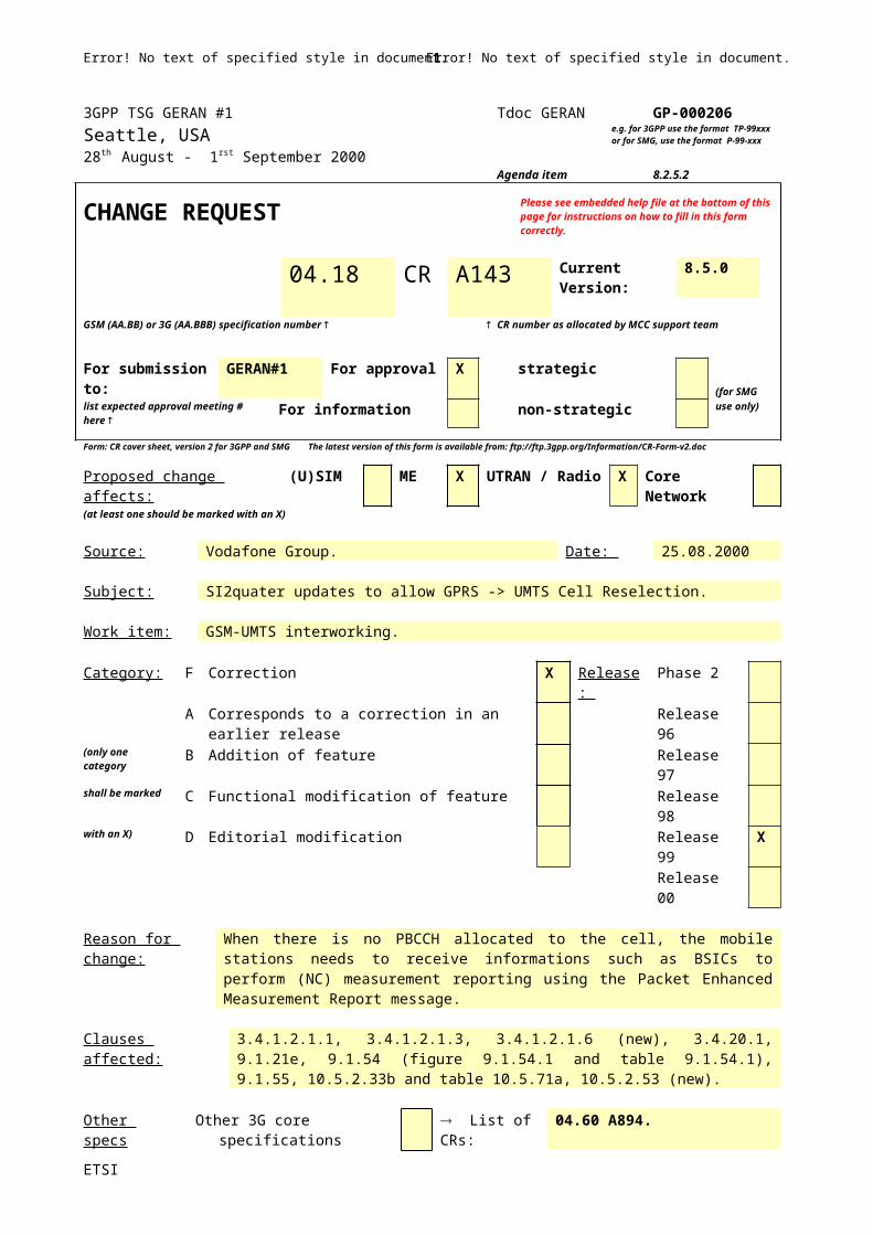
3GPP TSG GERAN #1 Tdoc GERAN GP-000206Seattle, USA28th August - 1rst September 2000
e.g. for 3GPP use the format TP-99xxx or for SMG, use the format P-99-xxx
Agenda item 8.2.5.2
CHANGE REQUEST Please see embedded help file at the bottom of thispage for instructions on how to fill in this form correctly.
04.18 CR A143 Current Version:
8.5.0
GSM (AA.BB) or 3G (AA.BBB) specification number CR number as allocated by MCC support team
For submission to:
GERAN#1 For approval X strategic(for SMG
list expected approval meeting # here
For information non-strategic use only)
Form: CR cover sheet, version 2 for 3GPP and SMG The latest version of this form is available from: ftp://ftp.3gpp.org/Information/CR-Form-v2.doc
Proposed change affects: (U)SIM ME X UTRAN / Radio X Core Network(at least one should be marked with an X)
Source: Vodafone Group. Date: 25.08.2000
Subject: SI2quater updates to allow GPRS -> UMTS Cell Reselection.
Work item: GSM-UMTS interworking.
Category: F Correction X Release: Phase 2A Corresponds to a correction in an earlier release Release 96
(only one category
B Addition of feature Release 97
shall be marked C Functional modification of feature Release 98with an X) D Editorial modification Release 99 X
Release 00
Reason for change:
When there is no PBCCH allocated to the cell, the mobile stations needs to receive informations such as BSICs to perform (NC) measurement reporting using the Packet Enhanced Measurement Report message.
Clauses affected: 3.4.1.2.1.1, 3.4.1.2.1.3, 3.4.1.2.1.6 (new), 3.4.20.1, 9.1.21e, 9.1.54 (figure 9.1.54.1 and table 9.1.54.1), 9.1.55, 10.5.2.33b and table 10.5.71a, 10.5.2.53 (new).
Other specs Other 3G core specifications List of CRs: 04.60 A894.affected: Other GSM core
specifications List of CRs:
MS test specifications List of CRs:BSS test specifications List of CRs:O&M specifications List of CRs:
Other comments:
*** first modification ***
3.4.1.2.1.1 Deriving the 3G Neighbour Cell list from the 3G Neighbour Cell Description:
This applies only to a multi-RAT MS. One or more instances of the Measurement Information message or SI2quater message may provide 3G Neighbour Cell Description information. This is used to build the 3G Neighbour Cell list. The 3G Neighbour Cell list may contain up to 96 3G Neighbour Cells.
Building of the 3G Neighbour Cell list:
ETSI
Error! No text of specified style in document. 1 Error! No text of specified style in document.

For each 3G Neighbour Cell Description received:
1. The order of indices is FDD Cell indices followed by the TDD Cell indices followed by CDMA 2000 Cell indices. The ordering of Cell indices within the same radio Access Technology shall be based on:
1.a For UMTS FDD: FDD ARFCNs are included as received in the order of each 3G Neighbour Cell description. Then for each FDD ARFCN, the concatenated Scrambling codes / Time Diversity parameters are ordered by increasing numbers.
21.b For UMTS TDD: TDD ARFCNs are included as received in the order of each 3G Neighbour Cell description. Then for each TDD ARFCN, the concatenated Cell Parameter / Sync Case / Time diversity parameters are ordered by increasing numbers.
31.c For CDMA 2000: Parameters defining each cell are included as received in the order of each 3G Neighbour Cell description.
Any 3G Neighbour Cell Description received is added to the 3G Neighbour Cell list, starting with the index equal to the parameter Index_Start_3G. If this parameter is not present then the value 0 shall be used
If the MS receives some 3G Neighbour Cell Description on some non-supported frequencies or Radio Access Technologies, this shall not be considered as an error. However, indices in the 3G Neighbour Cell list are incremented accordingly.
3.4.1.2.1.2 Deriving the GSM Neighbour Cell list from the BSICs and the BA (list)
One or more instances of the Measurement Information message may provide BSIC information. This is used to build the GSM Neighbour Cell list. The GSM Neighbour Cell list may contain up to 96 Neighbour Cells.
The BSICs are associated to the frequencies in the BA (list). The BSICs may be received before the corresponding BA (list). The first BSIC in each instance applies to the frequency in the BA (list) referenced by the parameter BA_Index_Start_BSIC. For each successive BSIC, one bit indicates if the BSIC applies to the same frequency as the previous BSIC or to the next frequency in the BA (list), as defined in sub-clause 9.1.54, Measurement Information message.
3.4.1.2.1.3 Deriving the Neighbour Cell list from the GSM Neighbour Cell list and the 3G Neighbour Cell list
For report with the ENHANCED MEASUREMENT REPORT message, the Neighbour Cell list is the concatenation of the GSM Neighbour Cell list and the 3G Neighbour Ccell list (if any). In this concatenation the value of the parameter Absolute_Index_Start_EMR is added to the 3G Neighbour Ccell list indices. The Neighbour Cell list may contain up to 96 Neighbour Cells.
NOTE: For report with the MEASUREMENT REPORT MESSAGE, the concatenated list is not used. Instead, the two lists are used separately, as defined in sub-clause 10.5.2.20, 'Measurement Results'.
3.4.1.2.1.4 Real Time Differences
One or more instances of the Measurement Information message may provide Real Time Difference information. This is used to build the Real Time Difference list. The Real Time Difference list may contain up to 96 Real Time Difference parameters.
Each frequency in the BA (list) can be associated to 0, 1 or more Real Time Difference parameters. The Real Time Difference parameters may be received before the corresponding BA (list). The parameter(s) BA_Index_Start_RTD in the structure indicate(s) the index of the frequency in the BA (list) to be taken as a starting reference. A structure is included for each frequency referenced. Each of those structures indicates if 0, 1 or more RTD parameters are present for this frequency. If the last frequencies in the BA (list) do not contain RTD information, the structure may not include the remaining frequencies, see sub-clause 9.1.54 'Measurement Information message'.
3.4.1.2.1.5 Report Priority Description
Report Priority information can be received in one instance of the MEASUREMENT INFORMATION message. Each Rep_Priority bit of this field relates to indices of the Neighbour Cell list, starting with index 0. The Report Priority information may be received before the corresponding Neighbour Cell list.
ETSI
Error! No text of specified style in document. 2 Error! No text of specified style in document.

Indices exceeding the value 95 shall be ignored. If there are less indices than the number of Neighbour Cells, the value 0 shall be assumed for the missing bits.
3.4.1.2.1.6 GPRS Report Priority Description, GPRS BSIC Description, GPRS Real Time Differences Description, GPRS Measurement Parameters, GPRS 3G Measurement Parameters and NC Measurement Parameters
This set of information may be received in SI2quater message(s) and is used for GPRS neighbour cell measurement or enhanced (NC) Measurement reporting when the cell has no PBCCH allocated, see GSM 04.60 sub-clause 5.6 (“Measurement reports”). The use of the parameters is similar to parameters without the term “GPRS”.
*** Next modified sub-clause ***
3.4.20 RR-Network Commanded Cell Change Order
This section is only applicable to mobiles supporting the <<GPRS>> option.
In dedicated mode or in group transmit mode, intracell or intercell change of channel(s) can be requested by the network RR sublayer. This change may be performed through the RR-network commanded cell change order procedure.
The purpose of the RR-network commanded cell change order procedure is to permit the complete modification of the channels allocated to the mobile station e.g. when the cell is changed. This procedure only commences while in dedicated mode or in group transmit mode.
The RR-network commanded cell change order procedure includes:
- The suspension of normal operation except for RR management (layer 3).
- The disconnection of the main signalling link, and of the other links via local end release (layer 2), and the disconnection of the TCH(s) if any.
- The disconnection and the deactivation of previously assigned channels and their release (layer 1).
The complete acquisition of BCCH or PBCCH messages of the target cell.
- The triggering of the establishment of a Temporary Block Flow.
The RR-network controlled cell change order procedure is always initiated by the network.
3.4.20.1 RR-network commanded cell change order initiation
The network initiates the RR-network controlled cell change order procedure by sending a RR-CELL CHANGE ORDER message to the mobile station on the main DCCH. The network then starts timer T3119.
When a handover has taken place during dedicated connection, the network shall send a RR-CELL CHANGE ORDER message to the mobile station in order to establish TBF. In this case the target cell is equal to the old cell.
When sending this message on the network side, and when receiving it on the mobile station side, all transmission of signalling layer messages except for those RR messages needed for this procedure and for abnormal cases, is suspended until resuming is indicated. These RR messages can be deduced from section 3.4.3 and 8.5.1 "Radio Resource management".
Upon receipt of the RR-CELL CHANGE ORDER message, the mobile station starts timer T3134, and initiates, as described in section 3.1.4, the release of link layer connections, disconnects the physical channels, commands the switching to the identified cell, performs a complete acquisition of BCCH or PBCCH messages (see GSM 04.60), and obeys the procedures relevant to the establishment of the Temporary Block Flow. The mobile station shall obey the RR-CELL CHANGE ORDER irrespective of whether or not the mobile station has any knowledge of the relative synchronisation of the target cell to the serving cell. 3G multi-RAT mobile station shall obey the RR-CELL CHANGE ORDER to a 3G Cell irrespective of whether or not the mobile station has synchronised to that cell.
ETSI
Error! No text of specified style in document. 3 Error! No text of specified style in document.

The RR-CELL CHANGE ORDER message contains:
- The characteristics of the new cell that are necessary to identify it (i.e. BSIC + BCCH frequency).; For a 3G multi-RAT mobile station, the RR-CELL CHANGE ORDER message may contain information on a 3G target cell; in this case BSIC and BCCH frequency shall be ignored ;
- the NC mode to be initially applied on the new cell.
The RR-CELL CHANGE ORDER does not contain a cipher mode setting IE. Any RR layer ciphering that may have been applied in dedicated mode shall not be applied to the target TBF or with the target cell.
*** next modified sub-clause ***
9.1.21e RR-Cell Change Order
This message is sent on the main DCCH by the network to the mobile station to order it to reselect a cell. For a 3G multi-RAT MS the target cell may be a 3G cell. See table 9.21e/GSM 04.18.
A mobile station that does not support the <<GPRPS>> option shall regard this message as an unknown message.
Message type: RR-CELL CHANGE ORDER
Significance: dual
Direction: network to mobile station
Table 9.21e/GSM 04.18: RR-CELL CHANGE ORDER message content
IEI Information element Type / Reference Presence Format LengthRR management Protocol Discriminator
Protocol Discriminator10.2
M V ½
Skip Indicator Skip Indicator10.3.1
M V ½
RR-Cell Change Order Message Type
Message Type10.4
M V 1
Cell Description Cell description10.5.2.2
M V 2
NC mode for target cell NC mode10.5.2.21c
M V 1/2
Spare half octet Spare half octet10.5.1.8
M V 1/2
19 3G Target Cell 3G Target Cell10.5.2.53
O TLV 3-6
9.1.21e.1 3G Target Cell
If this information element is present and not ignored (see 3G Target Cell, 10.5.2.53), the content of the Cell Description information element shall be ignored.
*** Next modified sub-clause ***
9.1.54 MEASUREMENT INFORMATION
This message is sent on the SACCH by the network to the mobile station. If not all information fits into one message, the remaining information will be sent in other instances of this message. This message can contain a combination of information for e.g. 3G Neighbour Cell Description, Real Time Differences, BSICs, Report priority, Measurement parameters or 3G Measurement parameters.
Message type: MEASUREMENT INFORMATION
Significance: dual
Direction: network to mobile station
ETSI
Error! No text of specified style in document. 4 Error! No text of specified style in document.

<Measurement information> ::=
< RR short PD : bit > -- See GSM 04.07< Message type : bit (5) > -- See 10.4< Short layer 2 header : bit (2) > -- See GSM 04.06
< BA_IND : bit >< 3G_BA_IND : bit >< MP_CHANGE_MARK : bit >< MI_INDEX : bit (4) >< MI_COUNT : bit (4) >< Report_Type : bit >< REPORTING_RATE : bit >< UNKNOWN_BSIC_REPORTING : bit >
{ 0L | 1H < 3G Neighbour Cells Description : < 3G Neighbour Cells Description struct >> }{ 0L | 1H < Real Time Difference Description : < Real Time Difference Description struct >> }{ 0L | 1H < BSIC Description : < BSIC Description struct >> }
{ 0L | 1H < REPORT PRIORITY Description : < REPORT PRIORITY Description struct >> }{ 0L | 1H < MEASUREMENT Parameters Description : < MEASUREMENT Parameters Description struct >> }{ 0L | 1H < 3G MEASUREMENT Parameters Description : < 3G MEASUREMENT Parameters Description struct >> }
< spare padding > ;
< 3G Neighbour Cells Description struct > : :=
0 | 1 < 3G_Wait : bit (3)> } 0 | 1 < Index_Start_3G : bit (7)> } 0 | 1 < Absolute_Index_Start_EMR : bit (7)> }{ 0 | 1 < UMTS FDD Description : < UMTS FDD Description struct >> }{ 0 | 1 < UMTS TDD Description : < UMTS TDD Description struct >> }{ 0 | 1 < CDMA2000 Description : < CDMA2000 Description struct >> } ;
< UMTS FDD Description struct > ::={{ 0 | 1 < Bandwidth_FDD : bit (3) > }{ 1 { < Repeated UMTS FDD Neighbour Cells : < Repeated UMTS FDD Neighbour Cells struct >> } ** 0 } ;
< Repeated UMTS FDD Neighbour Cells struct > ::={ 0 < FDD-ARFCN : bit (14) > | 1 < FDD-ARFCN-INDEX : bit (3) > }< Number_of_Scrambling_Codes_and_Diversity : bit (5) >< Range-1024-Format Scrambling Codes and Diversity Field : bit(p(Number_of_Scrambling_Codes_and_Diversity)) > ; -- p(x) defined in table 9.1.54.1a/GSM 04.18.
< UMTS TDD Description struct > ::=
{ 0 | 1 < Bandwidth_TDD : bit (3) > }{ 1 < Repeated UMTS TDD Neighbour Cells : Repeated UMTS TDD Neighbour Cells struct > } ** 0 } ;
< Repeated UMTS TDD Neighbour Cells struct > ::={ 0 < TDD-ARFCN : bit (14) > | 1 < TDD-ARFCN-INDEX : bit (3) > }< Number_of_Cell Parameters_and_sync cases_and_Diversity : bit (5) >< Range-512-Format Cell Parameters and syncs cases and Diversity : bit(q(Number_of_ Cell Parameters_and_sync cases_and_Diversity) > ; -- q(x) defined in table 9.1.54.1b/GSM04.18.
< CDMA 2000 Description struct > ::=
< cdma2000 frequency band : bit(5)>< cdma2000 frequency : bit(11)>< number_cdma2000_cells : bit (5) >
{ < Pilot PN offset : bit (9) >-- this information is enough for 1X Common Pilot
{0 | 1 {000 { < TD_MODE : bit (2)> <TD_POWER_LEVEL : bit (3) >}-- additional information for 1X Common Pilot with Transmit Diversity
ETSI
Error! No text of specified style in document. 5 Error! No text of specified style in document.

| 001 { < QOF : bit (2) > < WALSH_LEN_A : bit (3) > <AUX_PILOT_WALSH : bit(val(WALSH_LEN_A)+6) >}
-- additional information for 1X Auxiliary Pilot
| 010 { < QOF : bit (2) > < WALSH_LEN_B : bit (3) > < AUX_TD_WALSH : bit (val(WALSH_LEN_B)+6) >< AUX_TD_POWER_LEVEL : bit (2) > <TD_MODE : bit (2) >}
-- additional information for 1X Auxiliary Pilot with Transmit Diversity
| 011 { < SR3_PRIM_PILOT : bit (2) > < SR3_PILOT_POWER1 : bit (3) >< SR3_PILOT_POWER2 : bit(3)>}
-- additional information for 3X Common Pilot
| 110 { < SR3_PRIM_PILOT : bit (2) > < SR3_PILOT_POWER1 : bit (3) >< SR3_PILOT_POWER2 : bit (3) > < QOF : bit (2) >< WALSH_LEN_C : bit (3) > < AUX_WALSH_LEN : bit(val(WALSH_LEN_C)+6) >
{ 0 | 1 < QOF1 : bit (2) > < WALSH_LENGTH1 : bit (3) > < AUX_PILOT_WALSH1 : bit(val(WALSH_LENGTH1)+6) > }
{ 0 | 1 < QOF2 : bit (2) > < WALSH_LENGTH2 : bit (3) >< AUX_PILOT_WALSH2 : bit(val(WALSH_LENGTH2)+6)> } }
-- additional information for 3X Auxiliary Pilot}
}} * val(number_cdma2000_cells) ;
< Real Time Difference Description struct > ::={ 0 | 1 { 0 | 1 < BA_Index_Start_RTD : bit (5) > } --default value=0
< RTD Struct : < RTD6 Struct >>{ 0 < RTD Struct : < RTD6 Struct >> **1 } -- '0' indicates to increment by 1
-- the frequency in the BA (list)}{ 0 | 1 { 0 | 1 < BA_Index_Start_RTD : bit (5) > } --default value=0
< RTD Struct : < RTD126 Struct >>{ 0 < RTD Struct : < RTD126 Struct >> **1 } -- '0' indicates to increment by 1
-- the frequency in the BA (list)} ;
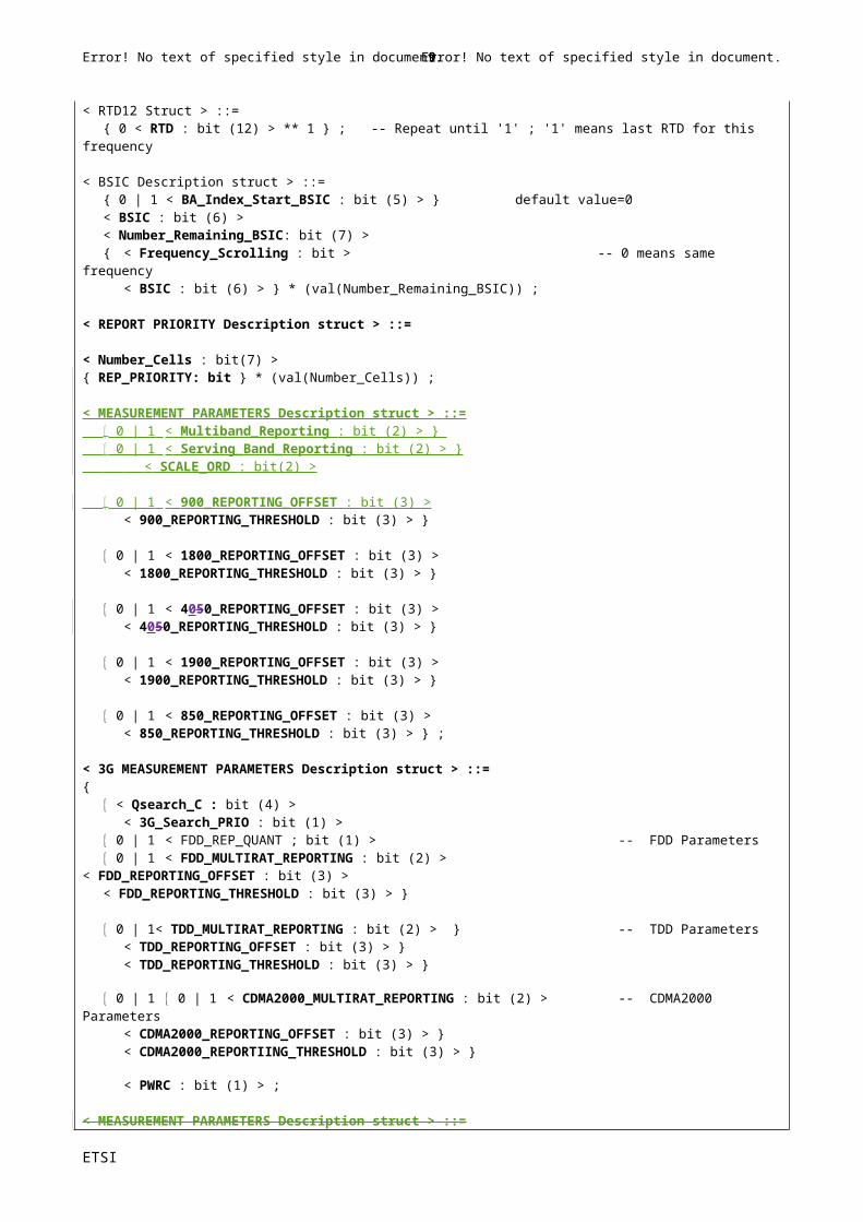
< RTD6 Struct > ::={ 0 < RTD : bit (6) > ** 1 } ; -- Repeat until '1' ; '1' means last RTD for this frequency
< RTD12 Struct > ::={ 0 < RTD : bit (12) > ** 1 } ; -- Repeat until '1' ; '1' means last RTD for this frequency
< BSIC Description struct > ::={ 0 | 1 < BA_Index_Start_BSIC : bit (5) > } default value=0< BSIC : bit (6) >< Number_Remaining_BSIC: bit (7) >{ < Frequency_Scrolling : bit > -- 0 means same frequency
< BSIC : bit (6) > } * (val(Number_Remaining_BSIC)) ;
< REPORT PRIORITY Description struct > ::=
< Number_Cells : bit(7) >{ REP_PRIORITY: bit } * (val(Number_Cells)) ;
< MEASUREMENT PARAMETERS Description struct > ::= 0 | 1 < Multiband_Reporting : bit (2) > } 0 | 1 < Serving_Band_Reporting : bit (2) > } < SCALE_ORD : bit(2) >
0 | 1 < 900_REPORTING_OFFSET : bit (3) >< 900_REPORTING_THRESHOLD : bit (3) > }
0 | 1 < 1800_REPORTING_OFFSET : bit (3) > < 1800_REPORTING_THRESHOLD : bit (3) > }
0 | 1 < 4050_REPORTING_OFFSET : bit (3) >
ETSI
Error! No text of specified style in document. 6 Error! No text of specified style in document.

< 4050_REPORTING_THRESHOLD : bit (3) > }
0 | 1 < 1900_REPORTING_OFFSET : bit (3) > < 1900_REPORTING_THRESHOLD : bit (3) > }
0 | 1 < 850_REPORTING_OFFSET : bit (3) > < 850_REPORTING_THRESHOLD : bit (3) > } ;
< 3G MEASUREMENT PARAMETERS Description struct > ::={
< Qsearch_C : bit (4) > < 3G_Search_PRIO : bit (1) >
0 | 1 < FDD_REP_QUANT ; bit (1) > -- FDD Parameters 0 | 1 < FDD_MULTIRAT_REPORTING : bit (2) >
< FDD_REPORTING_OFFSET : bit (3) >< FDD_REPORTING_THRESHOLD : bit (3) > }
0 | 1< TDD_MULTIRAT_REPORTING : bit (2) > } -- TDD Parameters< TDD_REPORTING_OFFSET : bit (3) > } < TDD_REPORTING_THRESHOLD : bit (3) > }
0 | 1 0 | 1 < CDMA2000_MULTIRAT_REPORTING : bit (2) > -- CDMA2000 Parameters< CDMA2000_REPORTING_OFFSET : bit (3) > } < CDMA2000_REPORTIING_THRESHOLD : bit (3) > }
< PWRC : bit (1) > ;
< MEASUREMENT PARAMETERS Description struct > ::={ 0 | 1 < Multiband_Reporting : bit (2) > } 0 | 1 < Serving_Band_Reporting : bit (2) > } < SCALE_ORD : bit(2) > 0 | 1 < 900_REPORTING_OFFSET : bit (3) >
Figure 9.1.54.1/GSM 04.18: Measurement Information message content
Table 9.1.54.1/GSM 04.18: Measurement Information information element details.
BA-IND (1 bit), BCCH allocation sequence number indication.The BA-IND is needed to allow the network to discriminate measurements results related to different GSM neighbour Cell lists sent to the MS, as described in sub-clause 3.4.1.2.1 'The Use of parameters from the Measurement Information/SI2quater messages'. The value of this parameter is reflected in the ENHANCED MEASUREMENT REPORT message and in the MEASUREMENT REPORT message.
3G-BA-IND (1 bit), 3G Sequence Number.The 3G-BA-IND parameter is needed to allow the network to discriminate measurement results related to different 3G Neighbour Cell lists sent to the MS, as described in sub-clause 3.4.1.2.1, 'The Use of parameters from the Measurement Information/Si2quater messages'. The value of this parameter is reflected in the ENHANCED MEASUREMENT REPORT and MEASUREMENT REPORT messages.
MP-CHANGE-MARK (1 bit), measurement parameters change mark.This parameter is used to indicate the MS a change of information concerning REPORT PRIORITY, MEASUREMENT INFORMATION and 3G MEASUREMENT INFORMATION, as described in sub-clause 3.4.1.2.1, 'The Use of parameters from the Measurement Information/SI2 quater messages'.
MI_INDEX (4 bits) and MI_COUNT (4 bits)The purpose of the MI_INDEX and MI_COUNT fields is to indicate the number of individual messages within the sequence of MEASUREMENT INFORMATION messages and to assign an index to identify each of them. The MI_INDEX field is binary coded, range 0 to 15, and provides an index to identify the individual MEASUREMENT INFORMATION message. The MI_COUNT field is binary coded, range 0 to 15, and provides the MI_INDEX value for the last (highest indexed) message in the sequence of MEASUREMENT INFORMATION messages.
Report_Type (1bit)This parameter is used to indicate to the mobile to use the Enhanced Measurement report or Measurement report messages for reporting:
ETSI
Error! No text of specified style in document. 7 Error! No text of specified style in document.

Bit0 The MS shall use the Enhanced Measurement Report message for reporting if at least one BSIC is allocated to each BA (list) frequency. 1 The MS shall use the Measurement Report message for reporting.
REPORTING_RATE (1 bit)This parameter is used for measurements, see GSM 05.08.bit0 SACCH rate reporting1 Reduced reporting rate allowed.
UNKNOWN_BSIC_REPORTING (1 bit)This field specifies if cells with unknown BSIC and allowed NCC part of BSIC are allowed to be reported or not, see GSM 05.08.bit0 Report on cells with unknown BSIC and allowed NCC part of BSIC is not allowed.1 Report on cells with unknown BSIC and allowed NCC part of BSIC is allowed.
3G Neighbour Cells Description:
The building of the 3G Neighbour Cell list and the ordering of indices within each Radio Access Technology is described in sub-clause 3.4.1.2.1.1, 'Deriving the 3G Neighbour Cell list from the 3G Neighbour Cell Description'.
3G-WAIT (3 bits)When 3G-BA-IND is received in a changed state, this parameter indicates the number of instances of MEASUREMENT INFORMATION messages that contain 3G Neighbour Cells Description which shall be received before the MS reports on the new 3G Neighbout Cell list. Two different instances of MEASUREMENT INFORMATION messages are two MEASUREMENT INFORMATION messages with different MI_INDEX. See sub-clause 3.4.1.2.1.
bit3 2 10 0 0 1 instance that contain 3G Neighbour Cell Description shall be received 0 0 1 2 instances that contain Neighbour Cell Description shall be received…1 1 1 8 instances that contain Neighbour Cell description shall be received
Index_Start_3G (7 bit)This optional information element indicates the binary value of the first index to use to build this instance of the 3G Neighbour Cell list. When missing, the value 0 is assumed. See sub-clause 3.4.1.2.1.1.
Absolute_Index_Start_EMR (7 bit)This parameter indicates in binary the value to be added to the indexes of the 3G Neighbour Cell list for reporting 3G Cells with the ENHANCED MEASUREMENT REPORT message (see sub-clause 3.4.1.2.1.1). If this parameter is absent, the same value as received in a previous instance (with the exception defined in 3.4.1.2.1 on the change of 3G-BA-IND) is assumed.
NOTE: This parameter is not used for reporting 3G Cells with the MEASUREMENT REPORT message, see sub-clause 10.5.2.20, 'Measurement Results'.
UMTS FDD Description:
Bandwidth_FDD (3bit field)This optional information element is defined in 3G TS 25.331.will be used for future releases of the protocol. When missing, this indicates the present FDD bandwidth. When present, this shall not be considered as an error; indices of the 3G Neighbour Cell list shall be incremented accordingly.
FDD_ARFCN (14 bit field)This optional information element is defined as the UARFCN in 3G TS 25.101. Any non-supported frequency shall not be considered as an errrordoes not trigger measurements.; The indicesex of the 3G Neighbour Cell list shall beis incremented accordingly.
FDD-ARFCN-INDEX (3 bit field)This field points to the absolute frequency received in the UMTS Freq list information element in the Channel Release
ETSI
Error! No text of specified style in document. 8 Error! No text of specified style in document.
message, see sub-clause 10.5.2.1d, UMTS frequency list. If there is no frequency associated to this value of the FDD-ARFCN-INDEX parameter, this shall not be considered as an errror;. The indicesex of the 3G Neighbour Cell list shall beis incremented accordingly.
Number_of_Scrambling_Codes_and_Diversity (n) (5 bit field)This optional field defines the decimal value of the number of Scrambling Codes/Diversity parameters (0–31).
Range-1024-Format Scrambling Codes and Diversity Field (p bit field)This field allows to compute a set of 10-bit-long Scrambling Codes and Diversity Parameters, re-using the Range 1024format compression algorithm, see Annex J: 'Algorithm to encode frequency list information'. The computationformulas for decoding are given in the 'Range 1024 format' sub-clause, 10.5.2.13.3. The consecutive parameters of thisfield are concatened, starting with the bit FDD_Indic0, and then w1, w2…
FDD_Indic0, information 0 indicator (1 bit):0 information '0000000000' is not a member of the set1 information '0000000000' is a member of the setNOTE: This bit FDD_Indic0 is equivalent than the bit F0 bit in the frequency list information element.
For each (10-bit-long) decoded Parameter, bits 1-9 are the Scrambling Codes and bit 10 is the corresponding Diversity Parameter.
The total number of bits p of this field depends on the value of the parameter Number_of_Scrambling_Codes_and_Diversity = n, as follows (with p=0 if n=0):
n p n p n p n p1 11 6 53 11 89 16 1232 20 7 61 12 96 17-31 03 29 8 68 13 103 18 04 37 9 75 14 110 - - 05 45 10 82 15 117 31 0
Table 9.1.54.1a.
If n=0, this indicates the 3G Neighbour Cell list index for report on RSSI, see GSM 05.08.
If n is equal or greater than 17, this shall not be considered as an error;. Tthe corresponding index in the 3G Neighbour Cell list shall be incremented by one.
Scrambling Codes (9 bit field)This parameter is defined in 3GPP TS 25.304.
Diversity (1 bit field)This parameter indicates if diversity is applied for the cell:Bit0 Diversity is not applied for this cell1 Diversity is applied for this cell.
UMTS TDD Description:
Bandwidth_TDD (3bit field)This optional information element refers tois defined in 3G TS 25.331.
Bit321000 3.84Mcps001 1.28McpsAll other values shall not be interpreted as an error; indexes of the 3G Neighbour Cell list shall be incremented accordingly (and no measurements can be performed).
TDD_ARFCN (14 bit field)This optional information element is defined as the UARFCN in 3G TS 25.102. Any non supported frequency shall not be considered as an errordoes not trigger measurements.; The indicesex of the 3G Neighbour Cell list shall beis incremented accordingly.
TDD-ARFCN-INDEX (3 bit field)This field points to the absolute frequency received in the UMTS Freq list information element in the Channel Release
ETSI
Error! No text of specified style in document. 9 Error! No text of specified style in document.
Ericsson User, BP1, 03/01/-1,
Page: 161

message, see sub-clause 10.5.2.1d, 'UMTS frequency list'. If there is no frequency associated to this value of the TDD-ARFCN-INDEX parameter, this shall not be considered as an errror;. The indicesex of the 3G Neighbour Cell list shall beis incremented accordingly.
Number_of_Cell Parameters_and_Sync Cases_and_Diversity (m) (5 bit field)This optional field defines the number of Cell Parameters/Sync Case/Time Diversity parameters (0–31).
Range-512-Format Cell Parameters and syncs cases and Diversity (q bit field)This field allows to compute a set of 9-bit-long Scrambling Codes and Diversity Parameters, re-using the Range 512format compression algorithm, see Annex J: 'Algorithm to encode frequency list information'. The computationformulas for decoding are given in the 'Range 512 format' sub-clause, 10.5.2.13.4, with w0=0. The consecutive parameters of this field are concatened, starting with the bit TDD_Indic0, and then w1, w2…
TDD_Indic0, information 0 indicator (1 bit):0 information '000000000' is not a member of the set1 information '000000000' is a member of the set
NOTE: This bit TDD_Indic0 is equivalent than the bit F0 bit in the frequency list information element.
For each (9-bit-long) decoded Parameter, bits 1-7 are the Cell Parameters, bit 8 is the Sync Case and bit 9 is the Diversity bit
The total number of bits q of this field depends on the value of the parameter Number_of_Cell Parameters_and_Sync Cases_and_Diversity = m, as follows (with q=0 if m=0):
m q m q m q m q m q1 10 6 47 11 78 16 106 21-31 0
18 7 54 12 84 17 112 22 03 26 8 60 13 90 18 117 23 04 33 9 66 14 96 19 122 - - 05 40 10 72 15 102 20 127 31 0
Table 9.1.54.1b.
If m=0 or m is equal or greater than 21, this shall not be considered as an error;. Tthe corresponding index in the 3G Neighbour Cell list shall be incremented by one.
Cell Parameter (7 bit field)This parameter is defined in 3GPP TS 25.304.
Sync Case (1 bit field)This parameter is defined in 3GPP TS 25.304.
Diversity (1 bit field)This parameter indicates if diversity is applied for the cell:Bit0 Diversity is not applied for this cell1 Diversity is applied for this cell.
CDMA 2000 Description:
cdma2000 frequency band (5 bit field)A binary representation of cdma2000 BAND_CLASS, as defined in TIA/EIA-IS-2000-5-A. The mobile station shall ignore all the information relative to a cdma2000 frequency band that it can not support.
cdma2000 frequency (5 bit field)A binary representation of cdma2000 CDMA_FREQ, as defined in TIA/EIA-IS-2000-5-A. The mobile station shall ignore all the information relative to a cdma2000 frequency that it can not support.
number_cdma2000_cells (5 bit field)This field indicates the number of CDMA 2000 neighbour cells.
cdma2000 Pilot PN offset (9 bit field)A binary representation of the PN offset of the Pilot PN sequence (in units of 64 cdma2000 1x-chips), PILOT_PN, as defined in TIA/EIA-IS-2000-5-A.
ETSI
Error! No text of specified style in document. 10 Error! No text of specified style in document.
Ericsson User, BP1, 03/01/-1,
Page: 162What about m=0?
Ericsson User, BP1, 03/01/-1,
Page: 162

TD_MODE (2 bit field)An indication of transmit diversity mode is specified in TIA/EIA-IS-2000-5-A. The mobile station shall ignore TD_MODE if it does not support 1X Common Pilot with Transmit Diversity.
TD_POWER_LEVEL (3 bit field)Power level of the Transmit Diversity Pilot relative to that of the Forward Pilot Channel as specified in TIA/EIA/IS-2000-5-A. The mobile station shall ignore TD_POWER_LEVEL if it does not support 1X Common Pilot with Transmit Diversity.
QOF (2 bit field)Quasi-orthogonal function index is defined in TIA/EIA/IS-2000-5-A. The mobile station shall ignore QOF if it does not support the quasi-orthogonal function.
WALSH_LEN_A, WALSH_LEN_B and WALSH_LEN_C (3 bit field each)A three bit field to indicate the length of the Walsh code for the pilot that is used in as the Auxiliary Pilot, and specified as WALSH_LEN in TIA/EIA/IS-2000-5-A. The mobile station shall ignore WALSH_LEN if it does not support 1X Auxiliary Pilot.
AUX_PILOT_WALSH (var. length)Indicates the walsh code corresponding to the Auxiliary Pilot, as specified in TIA/EIA/IS-2000-5-A. The mobile station shall ignore AUX_PILOT_WALSH if it does not support 1X Auxiliary Pilot.
AUX_TD_WALSH (var. length)Indicates the walsh code corresponding to the Auxiliary Transmit Diversity Pilot, as specified in TIA/EIA/IS-2000-5-A. The mobile station shall ignore AUX_TD_WALSH if it does not support 1X Auxiliary Pilot with Transmit Diversity.
AUX_TD_POWER_LEVEL (2 bit field)Power level of the Auxiliary Transmit Diversity Pilot relative to that of the Forward Pilot Channel as specified in TIA/EIA/IS-2000-5-A. The mobile station shall ignore AUX_TD_POWER_LEVEL if it does not support 1X Auxiliry Pilot with Transmit Diversity.
SR3_PRIM_PILOT (2 bit field)Position of the primary SR3 pilot as specified in TIA/EIA/IS-2000-5-A. The mobile station shall ignore SR3_PRIM_PILOT if it does not support 3X Common Pilot.
SR3_PILOT_POWER1 (2 bit field)Relative power level between the primary SR3 pilot and the pilot on the lower frequency of the two remaining SR3 frequencies, as specified in TIA/EIA/IS-2000-5-A. The mobile station shall ignore SR3_PILOT_POWER1 if it does not support 3X Common Pilot.
SR3_PILOT_POWER2 (2 bit field)Relative power level between the primary SR3 pilot and the pilot on the higher frequency of the two remaining SR3 frequencies, as specified in TIA/EIA/IS-2000-5-A. The mobile station shall ignore SR3_PILOT_POWER2 if it does not support 3X Common Pilot.
QOF1 (1 bit field), WALSH_LEN1 (3 bit field) and AUX_PILOT_WALSH1 (var. length)Are the corresponding quantities for pilot on the lower frequency of the two remaining SR3 frequencies, as specified in TIA/EIA/IS-2000-5-A. The mobile station shall ignore QOF1, WALSH_LEN1 and AUX_PILOT_WALSH1 if it does not support 3X Auxiliary Pilot.
QOF2 (2 bit field), WALSH_LENGTH2 (3 bit field) and AUX_PILOT_WALSH2 (var. length)Are the corresponding quantities for pilot on the higher frequency of the two remaining SR3 frequencies, as specified in TIA/EIA/IS-2000-5-A. The mobile station shall ignore QOF2, WALSH_LEN2 and AUX_PILOT_WALSH2 if it does not support 3X Auxiliary Pilot.
PRIORITY Description
REP_PRIORITY bit:0 Normal reporting priority1 High reporting priorityThe use of these bits is defined in sub-clause 3.4.1.2.1.5 'Report Priority Description'.
BSIC DescriptionBSIC parameters are used to create the GSM Neighbour Cell list, see sub-clause 3.4.1.2.1.2 'Deriving the GSM
ETSI
Error! No text of specified style in document. 11 Error! No text of specified style in document.

Neighbour Cell list from the BSICs and the BA (list)'. The first BSIC parameter received in the structure relates to the index in the BA(list) frequency referenced by the parameter BA_Index_Start_BSIC (index 0 if BA_Index_Start_BSIC is missing). Then the FREQUENCY_SCROLLING bit indicates wether the next BSIC in the structure relates to the same frequency in the BA(list), with '0', or if the next BSIC in the structure relates to the subsequent frequency in the BA (list), with '1'. Each next BSIC received within the structure creates a subsequent GSM Cell list index.When BSIC information is received in different instances, the first BSIC refering to a BA (list) index in one instance shall be allocated the subsequent GSM Cell list index than the last BSIC refering to the previous BA (list) index in another instance.
Real Time Difference Description
BA_Index_Start_RTD (5 bit field)This field indicates the BA (list) index for the first RTD parameter. When missing, the value '0' is assumed.
RTD (6 or 12 bit field) are defined in GSM 05.08.The use of these parameters is defined in sub-clause 3.4.1.2.1.4, 'Real Time Differences'.
MEASUREMENT PARAMETERS DescriptionThe fields of this Description are used for measurements as defined in GSM 05.08.PWRC, Power control indicator (1 bit field)
0 PWRC is not set1 PWRC is set
Any parameter present overwrites any old data held by the mobile station for this parameter. This means that the value corresponding to a parameter not included is not modified, with the exception defined in 3.4.1.2.1.
3G MEASUREMENT PARAMETERS DescriptionThe fields of this Description are used for measurements as defined in GSM 05.08.Any parameter present overwrites any old data held by the mobile station for this parameter. This means that the value corresponding to a parameter not included is not modified, with the exception defined in 3.4.1.2.1.
*** Next modified sub-clause ***
9.1.55 ENHANCED MEASUREMENT REPORT
This message containing measurement results is sent on the SACCH by the mobile to the network. See figure 9.1.55.1/GSM 04.18.
This message may contain reports on GSM and/or 3G Radio Access Technologies. Measurements are defined in GSM 05.08.
Message type: ENHANCED MEASUREMENT REPORT
Significance: dual
Direction: mobile station to network
ETSI
Error! No text of specified style in document. 12 Error! No text of specified style in document.

<Enhanced Measurement report> ::=
< RR short PD : bit > -- See GSM 04.07< Message type : bit (5) > -- See 10.4< Short layer 2 header : bit (2) > -- See GSM 04.06
< BA_USED : bit >< 3G_BA_USED : bit >< BSIC_Seen : bit >
< SCALE : bit >
{ 0 | 1 < Serving cell data : < Serving cell data struct >> }
{ 1 < Repeated Unknown_BSIC_Information : < Repeated Unknown_BSIC_Information struct >> } ** 0
{ 0 | 1 { 0 | 1 < REPORTING_QUANTITY : bit (6) > }**} - - bitmap type reporting
< spare padding > ;
< Serving cell data struct > ::=< DTX_USED : bit >< RXLEV_VAL : bit (6) >< RX_QUAL_FULL : bit (3) >< MEAN_BEP : bit (5) >< CV_BEP : bit (3) >< NBR_RCVD_BLOCKS : bit (5) > ;
< Repeated Unknown_BSIC_Information struct > ::=< BCCH-FREQ-NCELL : bit (5) >< BSIC : bit (6) >< RXLEV-NCELL : bit (6) > ;
Figure 9.1.55.1/GSM 04.18: Enhanced Measurement Report message content
*** Next modified sub-clause ***
10.5.2.33b SI 2quater Rest Octets
The SI 2quater Rest Octets information element contains neighbour cell lists for UTRAN cells.. For cell reselection, if the SI 2ter Rest Octets information element also contains information on 3G Cells, cell reselection shall be performed on the union of them.
The SI 2quater Rest Octets information element is a type 5 information element with 20 octet length.
ETSI
Error! No text of specified style in document. 13 Error! No text of specified style in document.

Table 10.5.71a: SI2quater message content
< SI2quater Rest Octets > ::=
< 3G-BA_IND : bit (1) >< MP_CHANGE_MARK : bit (1) >< SI2quater_INDEX : bit (4) >< SI2quater_COUNT : bit (4) >
{ 0 | 1 < 3G Neighbour Cells Description : < 3G Neighbour Cells Description struct >> }{ 0 | 1 < Measurement_Parameters Description : < Measurement Parameters Description struct >> }{ 0 | 1 < 3G Measurement Parameters Description : < 3G Measurement Parameters Description struct >> }
{ 0 | 1 < GPRS_Real Time Difference Description : < GPRS_Real Time Difference Description struct >> } { 0 | 1 < GPRS_BSIC Description : GPRS_BSIC Description struct > } { 0 | 1 < GPRS_REPORT PRIORITY Description : < GPRS_REPORT_PRIORITY Description struct >> } { 0 | 1 < GPRS_MEASUREMENT_Parameters Description : < GPRS_MEASUREMENT Parameters Description struct >> } { 0 | 1 < GPRS_3G_MEASUREMENT Parameters Description : < GPRS_3G MEASUREMENT Parameters Description struct >> } { 0 | 1 < NC Measurement Parameters : < NC Measurement Parameters struct >> }< spare padding > ;
< 3G Neighbour Cells Description struct > ::={ 0 | 1 < Index_Start_3G : bit (7) }{ 0 | 1 < Absolute_Index_Start_EMR : bit (7) }{ 0 | 1 < UMTS FDD Description : UMTS FDD Description struct >> }{ 0 | 1 < UMTS TDD Description : UMTS TDD Description struct >> } ;
< UMTS FDD Description struct > ::={ 0 | 1 < Bandwidth_FDD : bit (3) }{ 1 { < Repeated UMTS FDD Neighbour Cells : Repeated UMTS FDD Neighbour Cells struct >> } ** 0 } ;
< Repeated UMTS FDD Neighbour Cells struct > ::={ 0 < FDD-ARFCN : bit (14) > | 1 < FDD-ARFCN-INDEX : bit (3) > }< Number_of_Scrambling_Codes_and_Diversity : bit (5) >< Range-1024-Format Scrambling Codes and Diversity Field : bit(p(Number_of_Scrambling_Codes_and_Diversity)) > ; -- p(x) defined in table 10.5.71.a1/GSM 04.18
< UMTS TDD Description struct > : :={ 0 | 1 < Bandwidth_TDD : bit (3) }{ 1 { < Repeated UMTS TDD Neighbour Cells : Repeated UMTS TDD Neighbour Cells struct >> } ** 0 } ;
< Repeated UMTS TDD Neighbour Cells struct > ::={ 0 < TDD-ARFCN : bit (14) > | 1 < TDD-ARFCN-INDEX : bit (3) > }< Number_of_Cell Parameters_and_sync cases_and_Diversity : bit (5) >< Range-512-Format Cell Parameters and syncs cases and Diversity : bit(q(Number_of_Cell_Parameters_and_sync cases) > ; -- q(x) defined in table10.5.71.a2/GSM04.18
<MEASUREMENT PARAMETERS Description Struct > ::=< SERVING_BAND_REPORTING : bit (2) > ;
< 3G MEASUREMENT PARAMETERS Description struct > ::= < Qsearch_I : bit (4) > } < Qsearch_C_Initial : bit (1) > 0 | 1 < FDD_QOffset : bit (4) > -- FDD information
< FDD_REP_QUANT : bit (1) >< FDD_MULTIRAT_REPORTING : bit (2) >< FDD_Qmin : bit (3) > }
0 | 1 < TDD_QOffset : bit (4) > -- TDD information< TDD_MULTIRAT_REPORTING : bit (2) > } ;
< GPRS Real Time Difference Description struct > ::= { 0 | 1 { 0 | 1 < BA_Index_Start_RTD : bit (5) > } --default value=0 < RTD : < RTD6 Struct >> { 0 < RTD : < RTD6 Struct >> **1 } -- '0' : increment by 1 the index of the BA (list) frequency } { 0 | 1 { 0 | 1 < BA_Index_Start_RTD : bit (5) > } --default value=0
ETSI
Error! No text of specified style in document. 14 Error! No text of specified style in document.
Ericsson User, BP1, 03/01/-1,
Page: 254

< RTD : < RTD12 Struct >> { 0 < RTD : < RTD12 Struct >> **1 } -- '0' : increment by 1 the index of the BA (list) frequency } ;< RTD6 Struct > ::= { 0 < RTD : bit (6) > ** 1 } ; -- Repeat until '1' ; '1' means last RTD for this frequency< RTD12 Struct > ::= { 0 < RTD : bit (12) > ** 1 } ; -- Repeat until '1' ; '1' means last RTD for this frequency
< GPRS BSIC Description struct > ::= { 0 | 1 < BA_Index_Start_BSIC : bit (5) > } -- default value=0 < BSIC : bit (6) > < Number_Remaining_BSIC: bit (7) > { < Frequency_Scrolling : bit > -- 0 means same frequency < BSIC : bit (6) > } * (val(Number_Remaining_BSIC)) ;
< GPRS REPORT PRIORITY Description struct > ::=< Number_Cells : bit (7) >{ REP_PRIORITY: bit } * (val(Number_Cells)) ;
< GPRS MEASUREMENT PARAMETERS Description struct > ::=
{ 0 | 1 < Multiband_Reporting : bit (2) > } { 0 | 1 < Serving_Band_Reporting : bit (2) > } < SCALE_ORD : bit(2) >
{ 0 | 1 < 900_REPORTING_OFFSET : bit (3) > < 900_REPORTING_THRESHOLD : bit (3) > }
{0 | 1 < 1800_REPORTING_OFFSET : bit (3) > < 1800_REPORTING_THRESHOLD : bit (3) > }
{0 | 1 < 450_REPORTING_OFFSET : bit (3) > < 450_REPORTING_THRESHOLD : bit (3) > }
{0 | 1 < 1900_REPORTING_OFFSET : bit (3) > < 1900_REPORTING_THRESHOLD : bit (3) > }
{0 | 1 < 850_REPORTING_OFFSET : bit (3) > < 850_REPORTING_THRESHOLD : bit (3) > } ;
< GPRS 3G MEASUREMENT PARAMETERS Description struct > ::= < Qsearch_P : bit (4) > < 3G_Search_PRIO : bit > { 0 | 1 < FDD_REP_QUANT : bit > -- FDD Parameters < FDD_MULTIRAT_REPORTING : bit (2) > } { 0 | 1 < FDD_REPORTING_OFFSET : bit (3) > < FDD_REPORTING_THRESHOLD : bit (3) > }
{ 0 | 1 < TDD_MULTIRAT_REPORTING : bit (2) > } -- TDD Parameters { 0 | 1 < TDD_REPORTING_OFFSET : bit (3) > < TDD_REPORTING_THRESHOLD : bit (3) > } ;
< NC Measurement Parameters struct > ::= < NETWORK_CONTROL_ORDER : bit (2) > { 0 | 1 < NC_ NON_DRX_PERIOD : bit (3) > < NC_REPORTING_PERIOD_I : bit (3) > < NC_REPORTING_PERIOD_T : bit (3) > } ;
Note to the incorporator of CR: probably a new table should start here.3G-BA-IND (1 bit), 3G BCCH allocation sequence number indication.The 3G-BA-IND is needed to indicate new sets of 3G Neighbour Cells information, as described in sub-clause 3.4.1.2.1, The Use of parameters from the Measurement Information message/SI2quater. The value received is reflected in the MEASUREMENT REPORT and ENHANCED MEASUREMENT REPORT message.
ETSI
Error! No text of specified style in document. 15 Error! No text of specified style in document.
Ericsson User, BP1, 03/01/-1,
Page: 255A new table should start here with “information element description”.

MP_CHANGE_MARK (1 bit )
The MP_CHANGE_MARK field is changed each time MEASUREMENT INFORMATION or 3G MEASUREMENT INFORMATION has been updated in any instance of the SI2quater messages. A new value indicates that the mobile station shall re-read the MEASUREMENT and 3G MEASUREMENT INFORMATION from all the SI2quater messages, as described in sub-clause 3.4.1.2.1, The Use of parameters from the Measurement Information message/SI2quater. The coding of this field is network dependent.
SI2quater _INDEX (4 bit field)The SI2quater _INDEX field is used to distinguish individual SI2quater messages. The field can take the binary representation of the values 0 to n, where n is the index of the last SI2quater message. (SI2quater_COUNT).
SI2quater _COUNT (4 bit field)This field is coded as the binary representation of the SI2quater _INDEX for the last (highest indexed) individual SI2quater message.
UMTS FDD DESCRIPTION
Bandwidth_FDD (3 bit field)This optional information element is defined in 3G TS 25.331will be used for future releases of the protocol. When missing, this indicates the present FDD bandwidth. When present, this shall not be considered as an error; indices of the 3G Neighbour Cell list shall be incremented accordingly.
FDD_ARFCN (14 bit field)This optional information element is defined as the UARFCN 3G TS 25.101. Any non-supported frequency shall not be considered as an erroris ignored in this version of the protocol;. . The indicesex of the 3G Neighbour Cell list shall beis incremented accordingly.
FDD-ARFCN-INDEX (3 bit field)This field points to the absolute frequency received in the UMTS Freq list information element in the Channel Release message, see sub-clause 10.5.2.1d, 'UMTS frequency list'. If there is no frequency associated to this value of the FDD-ARFCN-INDEX parameter, this shall not be considered as an error;. The iIndicesex of the 3G Neighbour Cell list shall beis incremented accordingly.
Number_of_Scrambling_Codes_and_Diversity (n) (5 bit field)This optional field defines the number of Scrambling Codes/Diversity parameters (0–31).
Range-1024-Format Scrambling Codes and Diversity Field (p bit field)This field allows to compute a set of 10-bit-long Scrambling Codes and Diversity Parameters, re-using the Range 1024format compression algorithm, see Annex J: 'Algorithm to encode frequency list information'. The computationformulas for decoding are given in the 'Range 1024 format' sub-clause, 10.5.2.13.3. The consecutive parameters of thisfield are concatened, starting with the bit FDD_Indic0, and then w1, w2…
FDD_Indic0, information 0 indicator (1 bit):0 information '0000000000' is not a member of the set1 information '0000000000' is a member of the setNOTE: This bit FDD_Indic0 is equivalent tohan the bit F0 bit in the frequency list information element.
For each (10-bit-long) decoded Parameter, bits 1-9 are the Scrambling Codes and bit 10 is the corresponding Diversity Parameter.
The total number of bits p of this field depends on the value of the parameter Number_of_Scrambling_Codes_and_Diversity = n, as follows (with p=0 if n=0):
n p n p n p n p 1 11 6 53 11 89 16 1232 20 7 61 12 96 17-31 03 29 8 68 13 103 18 04 37 9 75 14 110 - - 05 45 10 82 15 117 31 0
ETSI
Error! No text of specified style in document. 16 Error! No text of specified style in document.
Ericsson User, BP1, 03/01/-1,
Page: 256
Ericsson User, BP1, 03/01/-1,
I have removed drawing lines here.
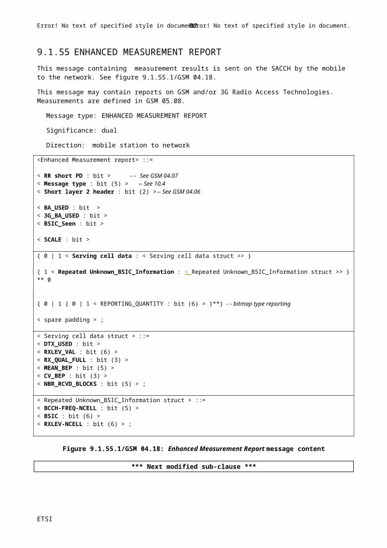
Table 10.5.71.a1
If n=0, this indicates the 3G Neighbour Cell list index for subsequent report on RSSI, see GSM 05.08.
If n is equal or greater than 17, this shall not be considered as an error;. Tthe corresponding index in the 3G Neighbour Cell list shall be incremented by one.
UMTS Scrambling code (9 bit field)This parameter is defined in 3GPP TS 25.304.
Diversity (1 bit field)This parameter indicates if diversity is applied for the cell:Bit0 Diversity is not applied for this cell1 Diversity is applied for this cell
UMTS TDD DESCRIPTION
Bandwidth_TDD (3 bit field)This optional information element refers tois defined in 3G TS 25.331.
Bit321000 3.84Mcps001 1.28McpsAll other values shall not be interpreted as an error; indexes of the 3G Neighbour Cell list shall be incremented accordingly (and no reporting can be performed).
TDD_ARFCN (14 bit field)This optional information element is defined as the UARFCN in 3G TS 25.102. Any non-supported frequency shall not be considered as an erroris ignored.; The indicesex of the 3G Neighbour Cell list shall beis incremented accordingly.
TDD-ARFCN-INDEX (3 bit field)This field points to the absolute frequency received in the UMTS Freq list information element in the Channel Release message, see sub-clause 10.5.2.1d, 'UMTS frequency list'. If there is no frequency associated to this value of the TDD-ARFCN-INDEX parameter, this shall not be considered as an error;. The indicesex of the 3G Neighbour Cell list shall beis incremented accordingly.
Number_of_Cell Parameters_and_Sync Sases_and_Diversity (m) (5 bit field)This optional field defines the number of Cell Parameters/Sync Case/Time Diversity parameters (0–31).
Range-512-Format Cell Parameters and syncs cases and Diversity (q bit field)This field allows to compute a set of 9-bit-long Scrambling Codes and Diversity Parameters, re-using the Range 512 format compression algorithm, see Annex J: 'Algorithm to encode frequency list information'. The computation formulas for decoding are given in the 'Range 512 format' sub-clause, 10.5.2.13.4, with w0=0. The consecutive parameters of this field are concatened, starting with the bit TDD_Indic0, and then w1, w2….TDD_Indic0, information 0 indicator (1 bit):
0information '000000000' is not a member of the set1information '000000000' is a member of the set
NOTE: This bit TDD_Indic0 is equivalent tohan the bit F0 bit in the frequency list information element.
For each (9-bit-long) decoded Parameter, bits 1-7 are the Cell Parameters, bit 8 is the Sync Case and bit 9 is the Diversity bit..
The total number of bits q of this field depends on the value of the parameter Number_of_Cell Parameters_and_Sync Cases_and_Diversity = m, as follows (with q=0 if m=0):
m q m q m q m q m q1 10 6 47 11 78 16 106 21-31 02 18 7 54 12 84 17 112 22 03 26 8 60 13 90 18 117 23 0
ETSI
Error! No text of specified style in document. 17 Error! No text of specified style in document.
Ericsson User, BP1, 03/01/-1,
I have removed drawing lines here.

4 33 9 66 14 96 19 122 24 05 40 10 72 15 102 20 127 31 0
Table 10.5.71.a2.
If m=0 or mn is equal or greater than 21, this shall not be considered as an error. The corresponding index in the 3G Neighbour Cell list shall be incremented by one.
Diversity (1 bit field)This parameter indicates if diversity is applied for the cell:Bit0 Diversity is not applied for this cell1 Diversity is applied for this cell
Cell Parameter (7 bit field)This parameter is defined in 3GPP TS 25.304.
Sync Case (1 bit field)This parameter is defined in 3GPP TS 25.304.
3G MEASUREMENT PARAMETERS Description
Qsearch_I (4 bit field)Qsearch_C_Initial (1 bit field)These parameters are defined in GSM 05.08.
FDD_Qoffset (3 bit field)FDD_REP_QUANT (1 bit field)FDD_MULTIRAT_REPORTING (2 bit field)These parameters are defined in GSM 05.08.
TDD_Qoffset (3 bit field)TDD_MULTIRAT_REPORTING (2 bit field)These parameters are defined in GSM 05.08.
GPRS PRIORITY Description
REP_PRIORITY bit:0 Normal reporting priority1 High reporting priorityThis information is used for GPRS Enhanced (NC) Reporting when the cell has no PBCCH allocated, see GSM 04.60 sub-clause 5.6.5 (“Report Priority Description”).The use of these bits is similar to the PRIORITY description, see sub-clause 3.4.1.2.1.5(“'Report Priority Description”).
GPRS BSIC Description
This information is used for GPRS Enhanced (NC) Measurement reporting when the cell has no PBCCH allocated, see GSM 04.60 sub-clause 5.6.3.2 (“Deriving the GSM Neighbour Cell list from the BSICs and frequency list”). The use of this information is similar to the BSIC Description, see sub-clause 3.4.1.2.1.2 (“Deriving the GSM Neighbour Cell list from the BSICs and the BA (list)”).
GPRS Real Time Difference Description
This information is used for GPRS neighbour cell measurement when the cell has no PBCCH allocated, see GSM 04.60 sub-clause 5.6.4 (“Real Time Differences”). The use of this information is similar to the Real Time Difference Deescription, see sub-clause 3.4.1.2.1.4 (“Real Time Differences”).
GPRS MEASUREMENT PARAMETERS DescriptionThis information is used for GPRS neighbour cell measurement when the cell has no PBCCH allocated, see GSM 04.60 sub-clause 5.6.6 (“GPRS Measurement Parameters and GPRS 3G Measurement Parameters”).
The fields of this Description are defined in GSM 05.08.
3G MEASUREMENT PARAMETERS Description
This information is used for GPRS neighbour cell measurement when the cell has no PBCCH allocated, see GSM 04.60
ETSI
Error! No text of specified style in document. 18 Error! No text of specified style in document.
Ericsson User, BP1, 03/01/-1,
Page: 258What about m=0?

sub-clause 5.6.6 (“GPRS Measurement Parameters and GPRS 3G Measurement Parameters”).
The fields of this Description are defined in GSM 05.08.
NC Measurement Parameters struct
Information in this structure is used when the cell has no PBCCH allocated, for (NC) measurement reporting. See GSM 04.60 sub-clause 5.6.1 (“Network Control (NC) measurement reporting”).
Coding of the fields is defined in GSM 04.60, sub-clause 11.2.23 (“PACKET SYSTEM INFORMATION TYPE5”).
*** Next modified sub-clause ***
10.5.2.53 3G Target Cell
The purpose of the 3G Target Cell information element is to indicate to the MS the target 3G Cell.
The 3G Target Cell is a type 4 information element with a minimum length of 3 octets and a maximum length of 6 octets.
If the 3G Target Cell information element contains information on both 3G UMTS FDD and 3G UMTS TDD, the information element shall be ignored by the receiver.
< 3G Target Cell >::=
< 0 0 0 1 0 0 1 1 > --type
< LENGTH OF 3G TARGET CELL : bit (8) > -- length following in octets
{ 0 | 1 < FDD-ARFCN : bit (14) > -- 3G UMTS FDD < Diversity : bit > { 0 | 1 < Bandwidth_FDD : bit (3) > } < SCRAMBLING_CODE : bit (9) > } { 0 | 1 < TDD-ARFCN : bit (14) > -- 3G UMTS TDD < Diversity : bit > { 0 | 1 < Bandwidth_TDD : bit (3) > } < Cell Parameter : bit (7) >
< Sync Case : bit > } ;
spare bits;
ETSI
Error! No text of specified style in document. 19 Error! No text of specified style in document.
Ericsson User, BP1, 03/01/-1,
Page: 259
Related Documents