Governor Control

Welcome message from author
This document is posted to help you gain knowledge. Please leave a comment to let me know what you think about it! Share it to your friends and learn new things together.
Transcript

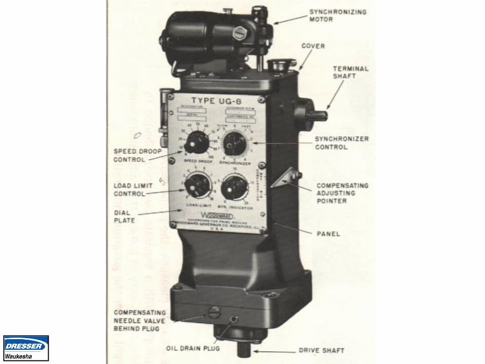
Governor Control
Governor Control

Your GoalYour Goal
To understand Governor control system design and maintenance practices for Woodward UG8 Hydraulic system, and 2301 Electronic governors.

Governor Oil SpecificationsGovernor Oil Specifications
• Use oils which have a high viscosity index.
• If oil temperature in the governor 180F, use S.A.E 40
• If oil temperature above 180F, use S.A.E 50
• Engine oil can be used if it meets these requirements.

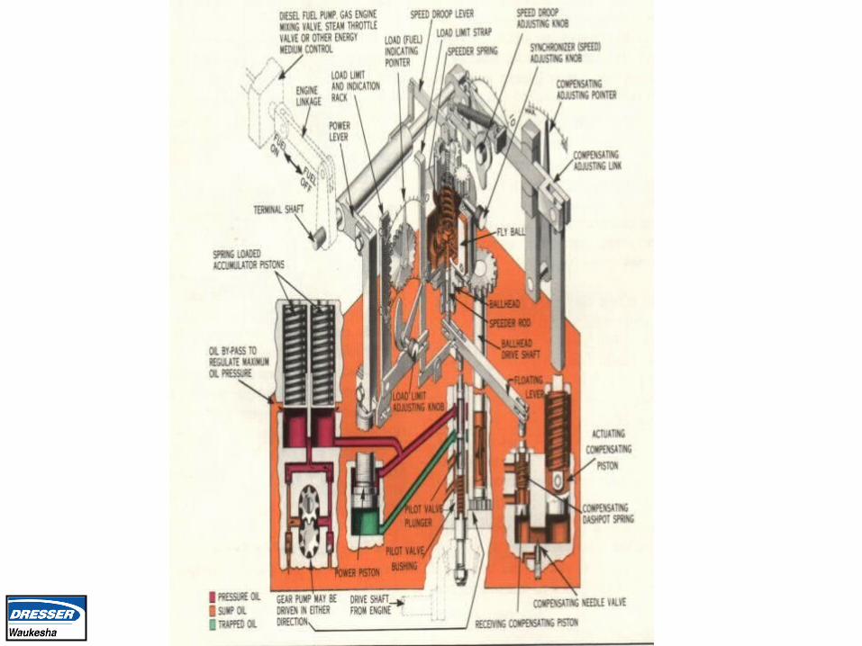
Compensation AdjustmentCompensation Adjustment
After the temperature of the engine and the oil in the governor have reached their normal operating values, you can make compensation process without loading the engine.
.
Compensation AdjustmentCompensation Adjustment
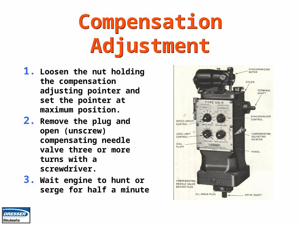
1. Loosen the nut holding the compensation adjusting pointer and set the pointer at maximum position.
2. Remove the plug and open (unscrew) compensating needle valve three or more turns with a screwdriver.
3. Wait engine to hunt or serge for half a minute
Compensation AdjustmentCompensation Adjustment
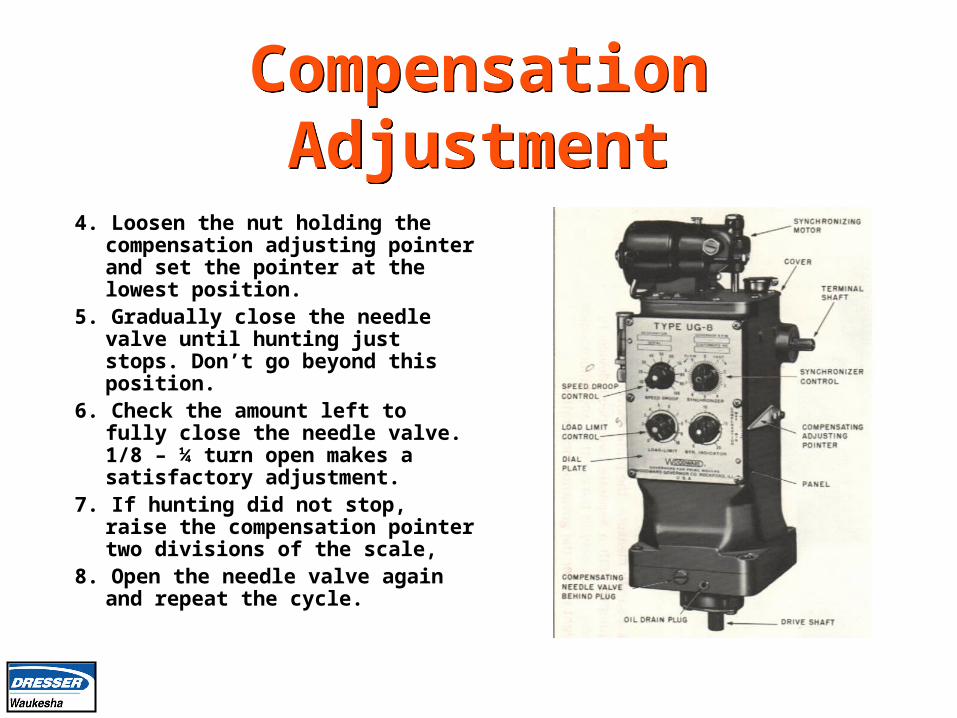
4. Loosen the nut holding the compensation adjusting pointer and set the pointer at the lowest position.
5. Gradually close the needle valve until hunting just stops. Don’t go beyond this position.
6. Check the amount left to fully close the needle valve. 1/8 – ¼ turn open makes a satisfactory adjustment.
7. If hunting did not stop, raise the compensation pointer two divisions of the scale,
8. Open the needle valve again and repeat the cycle.


WOODWARD UG8 OIL CHANGESWOODWARD UG8 OIL CHANGES
• Oil should be clean and free of foreign particles.
• Under favorable conditions, the oil may be used for approximately six months without changing.

What is synchronization?What is synchronization?
The matching of the output voltage wave form of one alternating current generator with the voltage wave form of another alternating current electrical system.

Synchronization of Engine
Generator Systems Synchronization of Engine
Generator Systems For two systems to be synchronized, five
conditions must be matched:
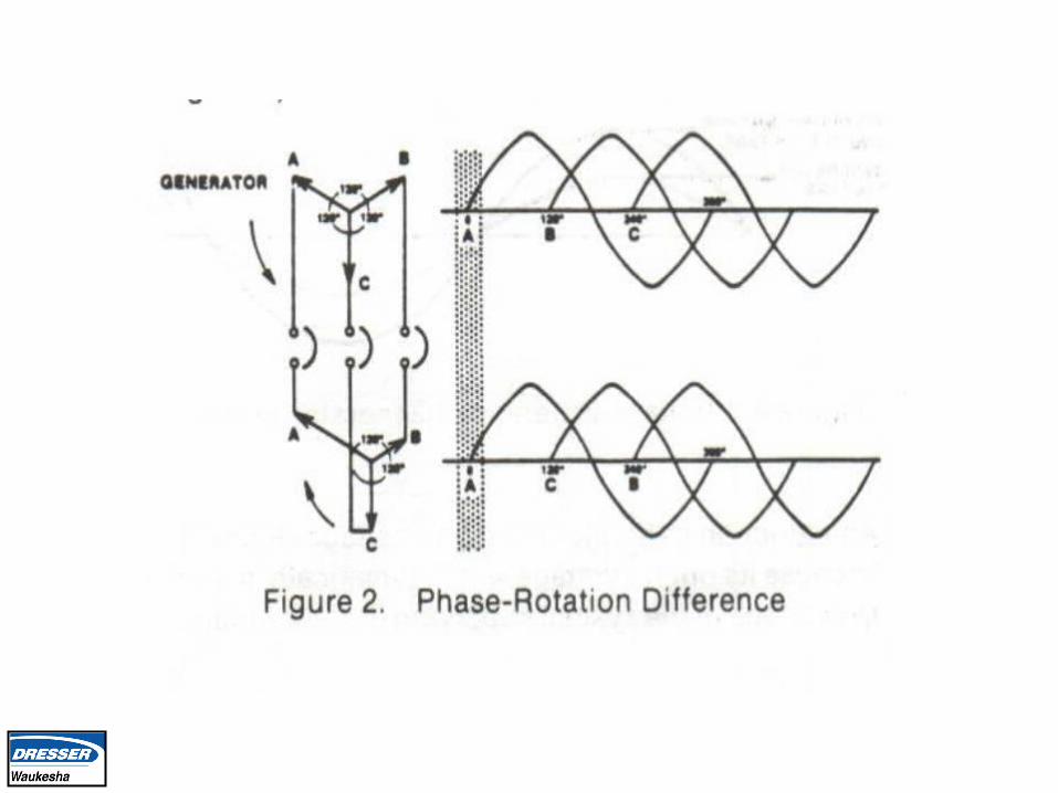
1. The number of phases in each system.
2. The direction of rotation of these phases.
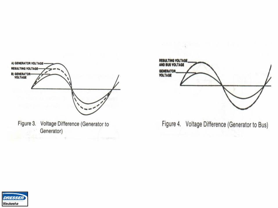
3. The voltage amplitudes of the two systems.
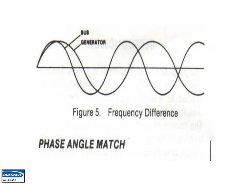
4. The frequencies of the two systems.
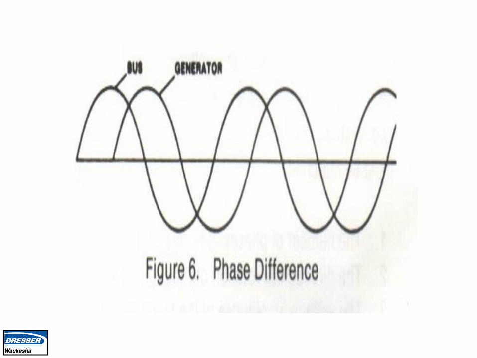
5. The phase angle of the voltage of the two systems.

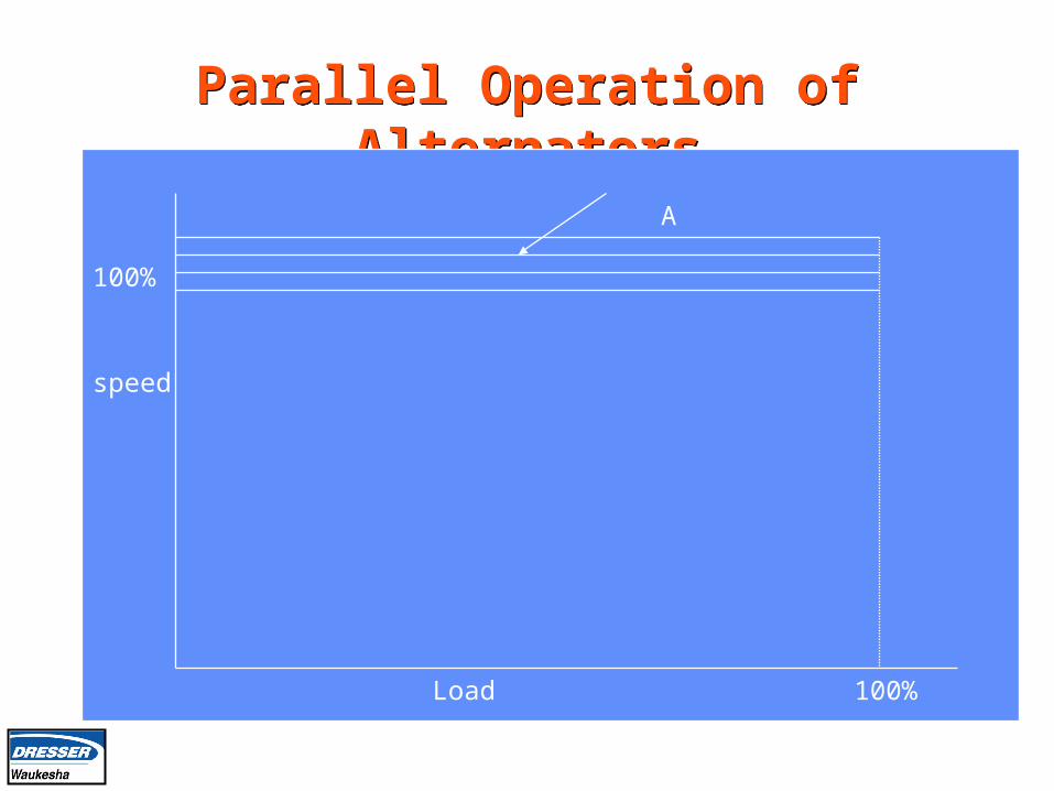
Parallel Operation of AlternatorsParallel Operation of Alternators
speed
Load 100%
100%
A
50%
Load
0 100%
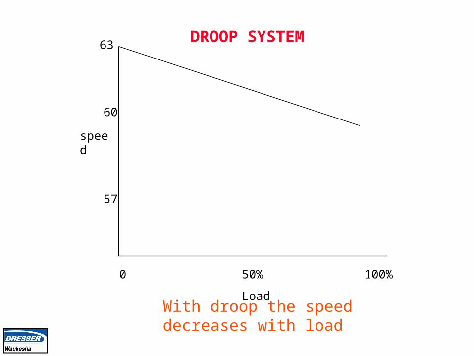
speed
57
60
63
With droop the speed decreases with load
DROOP SYSTEM

Parallel Operation of AlternatorsParallel Operation of Alternators
speed
Load 100%
100%
A
BC
50%
4%
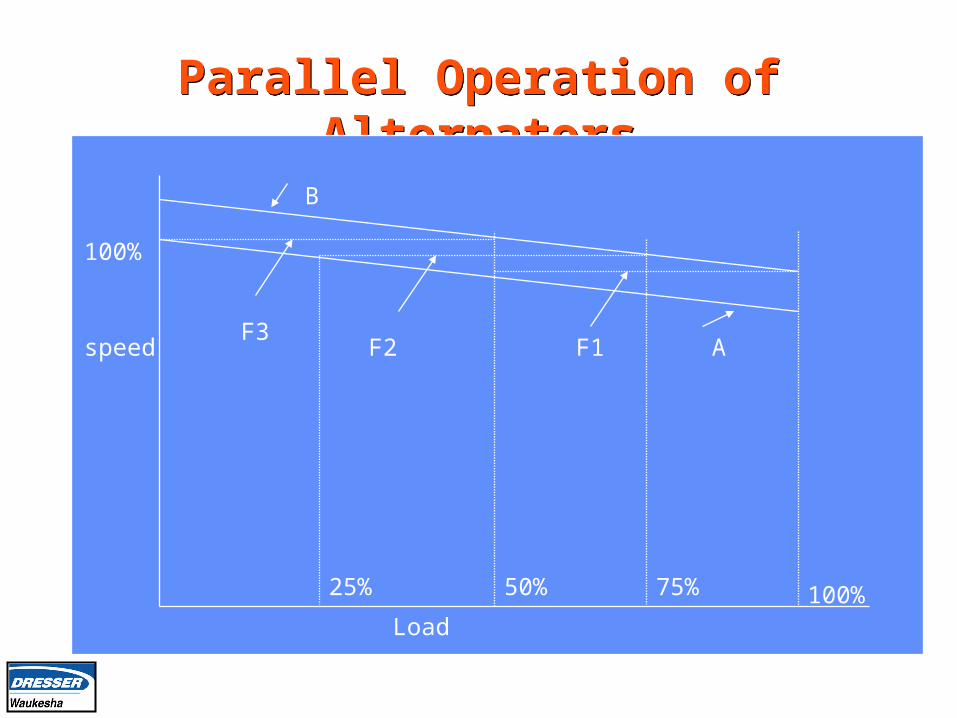
Parallel Operation of AlternatorsParallel Operation of Alternators
speed
Load100%
100%
50%25% 75%
A
B
F1F2F3
Droop / IsochronousDroop / Isochronous
If multiple generator sets operate in parallel in an isolated system, operate only one generator in an isochronous and all other generators in a droop mode.
The Isochronus generator is a swing unit

2301 Electric Governor2301 Electric Governor
Parallel lines
2301 Load sharing & speed control
ENGINEGEN
Bus
Actuator
DC Power 20 – 40 V DC
Magnetic Pickup
3 ph
PT
3 PH
CT

2301 Load Sharing Control Box2301 Load Sharing Control Box
Related Documents