INSTALLATION GUIDE hidglobal.com An ASSA ABLOY Group brand GOVERNMENT SOLUTIONS for Physical Access R10-H, RP10-H, R40-H, RP40-H, RK40-H, RPK40-H, RKCL40-P, RPKCL40-P, RKCLB40-P pivCLASS® Reader Parts 1 - Reader and base plate assembly 1 - Installation guide 2 - Terminal connector - terminal readers only RKCL40, RPKCL40 & RKCLB40 4 - M3.5 mm x 12 mm Phillips machine screw 4 - #6-32 x .375” Phillips self-tapping machine screw 4 - #6 x 1.5” Phillips sheet metal screw 3 - #6-32 x .4375” Spanner security screw, anti-tamper (black) 3 - #6-32 x .4375 Phillips security screw (black) 1 - Mounting gasket Recommended • Cable, 6 conductor, 22 or 24 AWG [65 mm or 51 mm] Twisted Pair, Over-All Shield (Belden 3108A or equivalent) - RS-485-FDX + power • Cable, 4 conductor, 22 or 24 AWG [65 mm or 51 mm] Twisted Pair, Over-All Shield and UL approved (Belden 3107A, or equivalent) - RS-485-HDX + power • Cable, 6 to 9 conductor, 22 or 24 AWG [65 mm or 51 mm] Over-All Shield, (Alpha 1296C or equivalent) - Wiegand + power • DC power supply • Metal or plastic double-gang junction box - RPKCL40 / RPKCL40 / RKCLB40 • Metal or plastic single-gang junction box - R10 / RP10 / R40 / RP40 / RK40 / RPK40 • Reader spacer when using metal junction boxes - see pivCLASS How to Order Guide • Security tool (for spanner security screw, anti-tamper) HID 04-0001-03 Specifications pivCLASS Protocol PRODUCT BASE PART NUMBER INPUT VOLTAGE (VDC) CURRENT OPERATING TEMPERATURE CABLE LENGTH UL REF NUMBER Standby AVG 1 Maximum AVG 2 PEAK 3 R10-H 900NHR 12VDC 60mA 100mA 200mA -30° to 150° F (-35° to 65° C) RS-485 = 500 ft - 22 AWG (152 m) 300 ft - 24 AWG (91 m) R10Ex 1 x 2 x 3 RP10-H 900PHR 75mA RP10Ex 1 x 2 x 3 R40-H 920NHR 65mA 110mA R40Ex 1 x 2 x 3 RP40-H 920PHR 85mA RP40Ex 1 x 2 x 3 RK40-H 921NHR 85mA 125mA 220mA RK40Ex 1 x 2 x 3 RPK40-H 921PHR 95mA RPK40Ex 1 x 2 x 3 RKCL40-P 923NPR 150mA 185mA 250mA -4° to 149° F (-20° to 65° C) RKCL40Ex 1 x 2 x 3 RPKCL40-P 923PPR RPKCL40Ex 1 x 2 x 3 RKCLB40-P 924NPR 165mA 215mA 275mA 14° to 122° F (-10° to 50° C) RKCLB40Ex 1 x 2 x 3 R10, RP10, R40, RK40, RP40 & RPK40 2 - M3.5 mm x 12 mm Phillips machine screw 3 - #6-32 x .375” Phillips self-tapping machine screw 2 - #6 x 1.5” Phillips sheet metal screw 1 - #6-32 x .375” Spanner security screw, anti-tamper 1 - Mounting gasket (optional, recommended for outdoor installation) 1 Standby AVG - RMS current draw without a card in the RF field. 2 Maximum AVG - RMS current draw during continuous PIV card reads. Not evaluated by UL. 3 Peak - highest instantaneous current draw during RF communication. UL Reference Number Deciphering x 1 Reader Colors: K = Black x 2 Wiring: N = Pigtail, T = Terminal x 3 Communications: N = No Module, R = RS-485 PLT-01134 A.7

Welcome message from author
This document is posted to help you gain knowledge. Please leave a comment to let me know what you think about it! Share it to your friends and learn new things together.
Transcript
INSTALLATION GUIDE
hidglobal.com An ASSA ABLOY Group brand
GOVERNMENT SOLUTIONS for Physical Access
R10-H, RP10-H, R40-H, RP40-H, RK40-H, RPK40-H, RKCL40-P, RPKCL40-P, RKCLB40-P
pivCLASS® Reader
Parts1 - Reader and base plate assembly1 - Installation guide2 - Terminal connector - terminal readers only
RKCL40, RPKCL40 & RKCLB404 - M3.5 mm x 12 mm Phillips machine screw4 - #6-32 x .375” Phillips self-tapping machine screw4 - #6 x 1.5” Phillips sheet metal screw3 - #6-32 x .4375” Spanner security screw, anti-tamper (black)3 - #6-32 x .4375 Phillips security screw (black)1 - Mounting gasket
Recommended• Cable, 6 conductor, 22 or 24 AWG [65 mm or 51 mm] Twisted Pair, Over-All Shield (Belden 3108A or equivalent) - RS-485-FDX +
power• Cable, 4 conductor, 22 or 24 AWG [65 mm or 51 mm] Twisted Pair, Over-All Shield and UL approved (Belden 3107A, or equivalent) -
RS-485-HDX + power• Cable, 6 to 9 conductor, 22 or 24 AWG [65 mm or 51 mm] Over-All Shield, (Alpha 1296C or equivalent) - Wiegand + power• DC power supply• Metal or plastic double-gang junction box - RPKCL40 / RPKCL40 / RKCLB40 • Metal or plastic single-gang junction box - R10 / RP10 / R40 / RP40 / RK40 / RPK40• Reader spacer when using metal junction boxes - see pivCLASS How to Order Guide• Security tool (for spanner security screw, anti-tamper) HID 04-0001-03
SpecificationspivCLASS Protocol
PRODUCT BASE PART NUMBER
INPUT VOLTAGE (VDC)
CURRENT OPERATING TEMPERATURE CABLE LENGTH UL REF
NUMBERStandby AVG1
Maximum AVG2 PEAK3
R10-H 900NHR
12VDC
60mA100mA
200mA-30° to 150° F(-35° to 65° C) RS-485 = 500 ft - 22 AWG
(152 m)300 ft - 24 AWG
(91 m)
R10Ex1x2x3
RP10-H 900PHR 75mA RP10Ex1x2x3
R40-H 920NHR 65mA110mA
R40Ex1x2x3
RP40-H 920PHR 85mA RP40Ex1x2x3
RK40-H 921NHR 85mA125mA 220mA
RK40Ex1x2x3
RPK40-H 921PHR 95mA RPK40Ex1x2x3
RKCL40-P 923NPR150mA 185mA 250mA -4° to 149° F
(-20° to 65° C)RKCL40Ex1x2x3
RPKCL40-P 923PPR RPKCL40Ex1x2x3
RKCLB40-P 924NPR 165mA 215mA 275mA 14° to 122° F(-10° to 50° C) RKCLB40Ex1x2x3
R10, RP10, R40, RK40, RP40 & RPK402 - M3.5 mm x 12 mm Phillips machine screw3 - #6-32 x .375” Phillips self-tapping machine screw2 - #6 x 1.5” Phillips sheet metal screw1 - #6-32 x .375” Spanner security screw, anti-tamper1 - Mounting gasket (optional, recommended for outdoor
installation)
1 StandbyAVG-RMScurrentdrawwithoutacardintheRFfield.2 MaximumAVG-RMScurrentdrawduringcontinuousPIVcardreads.NotevaluatedbyUL.3 Peak-highestinstantaneouscurrentdrawduringRFcommunication.
UL Reference Number Decipheringx1 Reader Colors: K = Blackx2 Wiring: N = Pigtail, T = Terminalx3 Communications: N = No Module, R = RS-485
PLT-01134 A.7

INSTALLATION GUIDE
hidglobal.com An ASSA ABLOY Group brand
© 2012 - 2017 HID Global Corporation/ASSA ABLOY AB. All rights reserved. HID, the HID logo, and pivCLASS are trademarks or registered trademarks of HID Global in the U.S. and/or other countries. All other trademarks, service marks, and product or service names are trademarks or registered trademarks of their respective owners.
This Installation Guide is for informational purposes only. HID makes no warranties, expressed or implied, in this summary. Company, product names and data used in sample output are fictitious. Specifications are subject to change without notice.
pivCLASS R10-H, RP10-H, R40-H, RP40-H, RK40-H, RPK40-H, RKCL40-P, RPKCL40-P, RKCLB40-P
Wiegand and OSDP Protocol
Installation
1 MountingAttach Backplate and Mounting Gasket to Junction Box.
Contactless Models Contact Models
1 CommunicationprotocolsotherthanWiegandorClock&Datarequireanadditionalhardwaremodulewhichincreasescurrentby30mA.
PRODUCT BASE PART NUMBER
INPUT VOLTAGE (VDC)
CURRENT1
OPERATING TEMPERATURE CABLE LENGTH5 UL REF
NUMBERStandby AVG2
Maximum AVG3 PEAK4
R10-H 900N
5-16VDC
12VDC for RS-485
60mA100mA
200mA
-30° to 150° F(-35° to 65° C)
Communication LinesWiegand = 500 ft - 22 AWG
(152 m)300 ft - 24 AWG
(91 m)
RS-485 = Max. bus length 4000 ft - 24 AWG
(1,219 m)
Max length between nodes: 1,640 ft - 24 AWG (500m)
R10Ex1x2x3
RP10-H 900P 75mA RP10Ex1x2x3
R40-H 920N 65mA110mA
R40Ex1x2x3
RP40-H 920P 85mA RP40Ex1x2x3
RK40-H 921N 85mA125mA 220mA
RK40Ex1x2x3
RPK40-H 921P 95mA RPK40Ex1x2x3
RKCL40-P 923N12VDC 150mA 185mA 250mA -4° to 149° F
(-20° to 65° C)
RKCL40Ex1x2x3
RPKCL40-P 923P RPKCL40Ex1x2x3
UL Reference Number Decipheringx1 ReaderColors: K=Black
x2 Wiring: N=Pigtail T=Terminalx3 Communications: N=NoModule, R=RS-485(OSDP)
2 StandbyAVG-RMScurrentdrawwithoutacardintheRFfield.3 MaximumAVG-RMScurrentdrawduringcontinuousPIVcardreads.
NotevaluatedbyUL.4 Peak-highestinstantaneouscurrentdrawduringRFcommunication.5 WiegandCableLengths:100ft(30.5m)[email protected]
500ft(152m)[email protected]
Junction box not included.
Mounting holes for US single-gang electrical boxes.
Install gasket for RK40 and RPK40 models.
Mounting holes for US double-gang electrical boxes.
Reverse Configuration Rotating the backplate 180° allows for placing the Contact reader on left and the Keypad reader on right.
See Section B Reconfigure Reader Assembly for instructions, before proceeding to Section 2.

INSTALLATION GUIDE
hidglobal.com An ASSA ABLOY Group brand
© 2012 - 2017 HID Global Corporation/ASSA ABLOY AB. All rights reserved. HID, the HID logo, and pivCLASS are trademarks or registered trademarks of HID Global in the U.S. and/or other countries. All other trademarks, service marks, and product or service names are trademarks or registered trademarks of their respective owners.
This Installation Guide is for informational purposes only. HID makes no warranties, expressed or implied, in this summary. Company, product names and data used in sample output are fictitious. Specifications are subject to change without notice.
pivCLASS R10-H, RP10-H, R40-H, RP40-H, RK40-H, RPK40-H, RKCL40-P, RPKCL40-P, RKCLB40-P
2 Wiring
Pigtail Terminal Description Pigtail Terminal Description
Yellow P1-1 Beeper Input Red / Green P2-7 *GPIO1/OSDP (RS485-FDX/HDX-A)
Orange P1-2 LED Input (GRN) Tan P2-6 *GPIO2/OSDP (RS485-FDX/HDX-B)
Black P1-3 Ground (RTN) Violet P2-5 **Open Collector Output / Tamper
Red P1-4 +VDC White P2-4 ***Wiegand Data 1 / Clock
Drain P1-5 Unused Green P2-3 ***Wiegand Data 0 / Data
Brown P1-6 LED Input (RED) Pink P2-2 *GPIO3 (RS485-FDX-Z)
Blue P1-7 Hold Input Gray P2-1 *GPIO4 (RS485-FDX-Y)
*RS-485applicableforpivCLASSreaders.**TamperOutput-Whenactivated,outputsynchronizestoground(default).***Dependentuponreaderconfiguration.SeetheHTOGforWiegandandClock-in-Dataconfigurations.
ATTENTIONObserveprecautionsforhandling
ELECTROSTATICSENSITIVEDEVICES
P1
P2
BeeperGRN LED
GND+VDC
DRAINRED
HOLD
GPIO1GP102OC/TMPRDATA1/CLKDATA2/DATAGPIO3GPIO4
BeeperGRN LED
GND+VDC
DRAINRED
HOLD
GPIO1GP102OC/TMPRDATA1/CLKDATA2/DATAGPIO3GPIO4
18 in(0.46 m)
BEEP (YEL)GRN LED (ORN)
GND (BLK)+VDC (RED)
DRAIN (BARE)RED LED (BRN)
HOLD (BLU)GPIO1(RED/GRN)
GPIO2 (TAN)OC/TMPR (VIO)DATA1 (WHT)DATA2 (GRN)GPIO3 (PINK)GPIO4 (GRAY)
Terminal ReaderPigtail Reader(Terminalblockandmodule
positionvaries)(Modulepositionvaries)
Notes:1.PreviousiCLASSreadershadreversedRS-485wiring(P2-7&P2-6-A&B).WhenupgradingtoapivCLASSreader,ensureproperconnectionsasdefinedbelow.
2.Wiringthereaderincorrectlymaypermanentlydamagethereader.
3.Forcablelengthsgreaterthan200ft.(61m)orEMFinterference,install120Ω+/-2ΩresistoracrossRS-485terminationends.
4.ItispossibletoreuseexistingWiegandwiringforOSDP,however,usingsimplestrandedcable(typicalofWiegandaccesscontrolreaders)usuallydoesnotmeetRS-485twistedpairrecommendations.

INSTALLATION GUIDE
hidglobal.com An ASSA ABLOY Group brand
© 2012 - 2017 HID Global Corporation/ASSA ABLOY AB. All rights reserved. HID, the HID logo, and pivCLASS are trademarks or registered trademarks of HID Global in the U.S. and/or other countries. All other trademarks, service marks, and product or service names are trademarks or registered trademarks of their respective owners.
This Installation Guide is for informational purposes only. HID makes no warranties, expressed or implied, in this summary. Company, product names and data used in sample output are fictitious. Specifications are subject to change without notice.
pivCLASS R10-H, RP10-H, R40-H, RP40-H, RK40-H, RPK40-H, RKCL40-P, RPKCL40-P, RKCLB40-P
3 Attach to BackplateContactless Models
Contact Models
Default: Slide Reader Assembly towards the right to lock.
Attach Reader InstallSecurityScrew
Reversed Configuration: Slide Reader Assembly to the left to lock.

INSTALLATION GUIDE
hidglobal.com An ASSA ABLOY Group brand
© 2012 - 2017 HID Global Corporation/ASSA ABLOY AB. All rights reserved. HID, the HID logo, and pivCLASS are trademarks or registered trademarks of HID Global in the U.S. and/or other countries. All other trademarks, service marks, and product or service names are trademarks or registered trademarks of their respective owners.
This Installation Guide is for informational purposes only. HID makes no warranties, expressed or implied, in this summary. Company, product names and data used in sample output are fictitious. Specifications are subject to change without notice.
pivCLASS R10-H, RP10-H, R40-H, RP40-H, RK40-H, RPK40-H, RKCL40-P, RPKCL40-P, RKCLB40-P
4 Power & TestingContactless Models
Contact Models
Turn on power Test card
Note: Withakeypadreaderoperatingas26bitemulation,uponpowerupyouhave5secondstoentertheFacilityCodefollowedby#.Ifunsuccessful,thereaderLEDdisplayssolidRed.Power-cyclethereaderandretryenteringtheFacilityCode.TheFacilityCodeneedstobemanuallyenteredas3digits(forexample,iftheFacilityCodeis10,enter0-1-0-#).SEreadersonlyuseFacilityCodesbetween1-255.ThereisnodefaultFacilityCode.OncetheFacilityCodehasbeenentered,theLEDwilldisplayVioletandthentoafinalRed.Thenpower-cyclethereader.Whenusingakeypad,ifthereare2shortbeepsafterenteringyourPIN,thereaderdoesnothaveaFacilityCodeconfiguredyet.Inthisevent,anAdministratorwillneedtopower-cyclethereaderandentertheFacilityCodebeforethereaderwillacceptyourPIN.

INSTALLATION GUIDE
hidglobal.com An ASSA ABLOY Group brand
© 2012 - 2017 HID Global Corporation/ASSA ABLOY AB. All rights reserved. HID, the HID logo, and pivCLASS are trademarks or registered trademarks of HID Global in the U.S. and/or other countries. All other trademarks, service marks, and product or service names are trademarks or registered trademarks of their respective owners.
This Installation Guide is for informational purposes only. HID makes no warranties, expressed or implied, in this summary. Company, product names and data used in sample output are fictitious. Specifications are subject to change without notice.
pivCLASS R10-H, RP10-H, R40-H, RP40-H, RK40-H, RPK40-H, RKCL40-P, RPKCL40-P, RKCLB40-P
A Biometric ReaderProper Usage
Ensure a good quality Contact:
• Do not press too hard
• Do not move during image acquisition
• Leave your finger on the sensor at least 2 seconds
• Do not slide or roll your finger across the sensor
CleaningFor optimum performance, it is recommended that the user clean the bio-reader periodically.
The use of a dry cloth is recommended to clean the acquisition surface.
Caution: Acidic liquids, alcohol or abrasive materials are prohibited.
In order not to scratch the surface, remove all dust and residue with gentle movements.
Acquisition Surface
INSTALLATION GUIDE
hidglobal.com An ASSA ABLOY Group brand
© 2012 - 2017 HID Global Corporation/ASSA ABLOY AB. All rights reserved. HID, the HID logo, and pivCLASS are trademarks or registered trademarks of HID Global in the U.S. and/or other countries. All other trademarks, service marks, and product or service names are trademarks or registered trademarks of their respective owners.
This Installation Guide is for informational purposes only. HID makes no warranties, expressed or implied, in this summary. Company, product names and data used in sample output are fictitious. Specifications are subject to change without notice.
pivCLASS R10-H, RP10-H, R40-H, RP40-H, RK40-H, RPK40-H, RKCL40-P, RPKCL40-P, RKCLB40-P
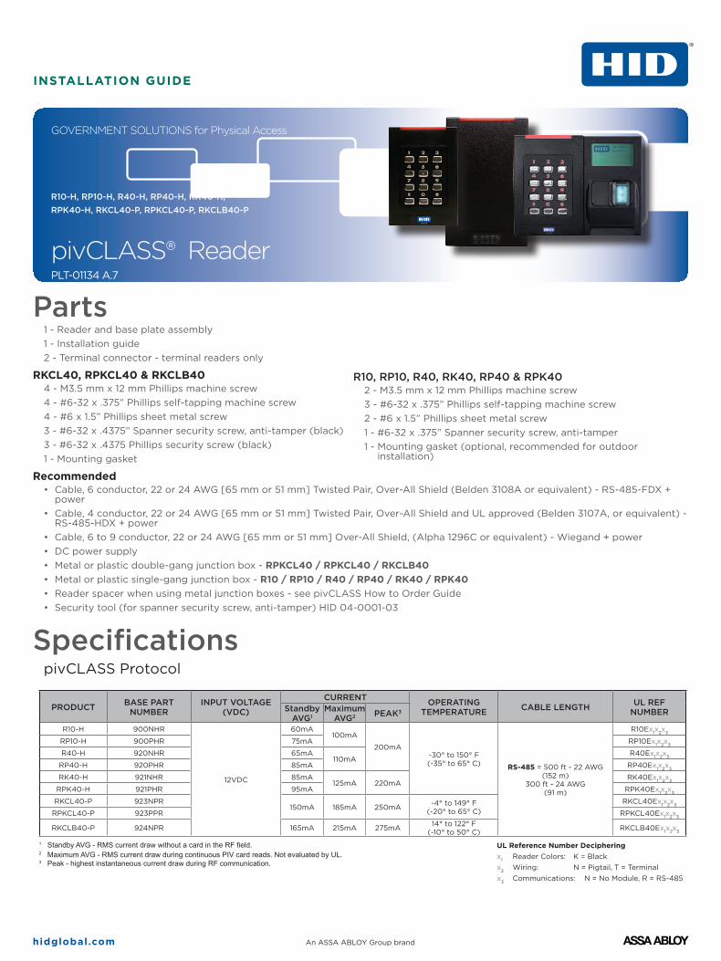
B Reconfigure Reader AssemblyThe following steps reconfigure the reader assembly to position
the Contact reader component on the left side of the assembly.
1. Disassemble the reader.
• Remove the Keypad reader from the backplate
• Carefully unplug the ribbon cable from the module in the back of the Keypad reader. Caution: Do not pull on the ribbon cable as this may damage the connection to the connector.
• Remove the Contact reader from the backplate
• Gently pull the ribbon cable through the backplate
2. Reassemble with the Contact reader on the left side of the assembly.
• Rotate the backplate so that the large cutout for the power cable is on the left
• Gently route the ribbon cable back through the backplate slots, as shown below
• Plug the ribbon cable back into the module (back of Keypad reader) and ensure module is fully seated into the reader
• Attach the Contact reader to the backplate (this must be installed first, as the Keypad Reader will fit slightly over the Contact reader)
• Attach the Keypad reader to the backplate (power cable must be threaded through the large square cutout on the backplate)
• Return to Section 2
Contact reader Keypad reader
Backplate
Ribbon cable
Keypad reader
Contact reader
Backplate
Ribbon cable
Contact reader Keypad reader
hidglobal.com An ASSA ABLOY Group brand
INSTALLATION GUIDE pivCLASS R10-H, RP10-H, R40-H, RP40-H, RK40-H, RPK40-H, RKCL40-P, RPKCL40-P, RKCLB40-P
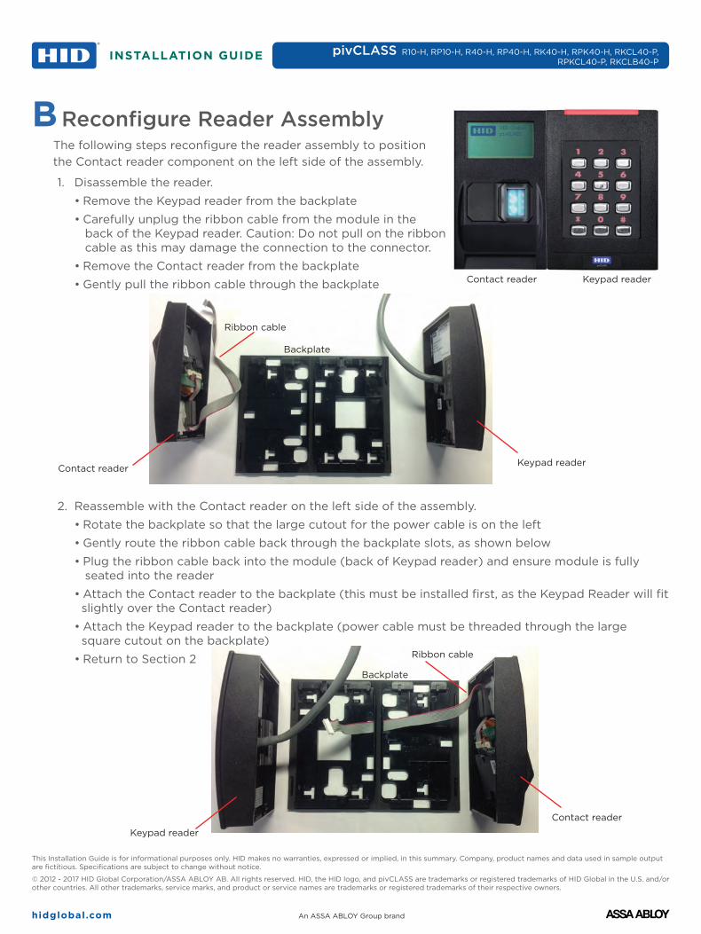
C Credential Presentation Best PracticesTo ensure a successful read of a PIV card:
1. Hold card between the thumb and index finger.
2. Present the card so that the index finger creates a spacing between the card and the reader face. Do not place the card flat on the reader.
3. Place the card parallel to the reader form factor. Do not angle to the right or left
4. Place the card parallel to the reader face. Do not angle the card up or down from the reader face.
ULConnect only to a Listed Access Control / Burglary power-limited power supply. These readers are intended to be used with listed (UL294) control equipment.All models are suitable for outdoor use.Evaluated for use over Wiegand and RS-485 communications.Evaluated for use with the M2000 pivCLASS Authentication Module as well as Standard Wiegand and OSDP panels.
FCC CertiFiCationCAUTION: Any changes or modifications to this device not explicitly approved by manufacturer could void your authority to operate this equipment.This device complies with part 15 of the FCC Rules. Operation is subject to the following two conditions: (1) This device may not cause harmful interference, and (2) this device must accept any interference received, including interference that may cause undesired operation.
HID Global
Americas & Corporate611 Center Ridge DriveAustin, TX 78758USASupport: 866-607-7339Fax: 949-732-2120
Asia Pacific19/F 625 King's RoadNorth Point, Island EastHong KongSupport: 852-3160-9833Fax: 852-3160-4809
Europe, Middle East & AfricaPhoenix RoadHaverhill, Suffolk CB9 7AEEnglandSupport: 55 11 5514-7100Fax: 55 11 5514-7109
For additional offices around the world, see www.hidglobal.com corporate offices.HID Global Customer Support: www.hidglobal.com/customer-service
Equipment8T29ACC Control Reader
General SignalingEquipment
Related Documents