Gong, X., Liu, L., Scarpa, F., Leng, J., & Liu, Y. (2017). Variable stiffness corrugated composite structure with shape memory polymer for morphing skin applications. Smart Materials and Structures, 26(3), [035052]. https://doi.org/10.1088/1361-665X/aa516d Peer reviewed version Link to published version (if available): 10.1088/1361-665X/aa516d Link to publication record in Explore Bristol Research PDF-document This is the author accepted manuscript (AAM). The final published version (version of record) is available online via IOP at http://iopscience.iop.org/article/10.1088/1361-665X/aa516d. Please refer to any applicable terms of use of the publisher. University of Bristol - Explore Bristol Research General rights This document is made available in accordance with publisher policies. Please cite only the published version using the reference above. Full terms of use are available: http://www.bristol.ac.uk/red/research-policy/pure/user-guides/ebr-terms/

Welcome message from author
This document is posted to help you gain knowledge. Please leave a comment to let me know what you think about it! Share it to your friends and learn new things together.
Transcript

Gong, X., Liu, L., Scarpa, F., Leng, J., & Liu, Y. (2017). Variablestiffness corrugated composite structure with shape memory polymerfor morphing skin applications. Smart Materials and Structures, 26(3),[035052]. https://doi.org/10.1088/1361-665X/aa516d
Peer reviewed version
Link to published version (if available):10.1088/1361-665X/aa516d
Link to publication record in Explore Bristol ResearchPDF-document
This is the author accepted manuscript (AAM). The final published version (version of record) is available onlinevia IOP at http://iopscience.iop.org/article/10.1088/1361-665X/aa516d. Please refer to any applicable terms ofuse of the publisher.
University of Bristol - Explore Bristol ResearchGeneral rights
This document is made available in accordance with publisher policies. Please cite only thepublished version using the reference above. Full terms of use are available:http://www.bristol.ac.uk/red/research-policy/pure/user-guides/ebr-terms/

1
Variable stiffness corrugated composite structure with shape memory polymer for morphing
skin applications
Xiaobo Gong1, Liwu Liu2, Fabrizio Scarpa3,*, Jinsong Leng1, and Yanju Liu2,*
1Centre for Composite Materials and Structures, Harbin Institute of Technology, Harbin HIT Science Park, No. 2 YiKuang Street, Harbin, 150080, PR China
2Department of Astronautical Science and Mechanics, Harbin Institute of Technology P.O. Box 301, No. 92 West Dazhi Street, Harbin 150001, PR China
3Advanced Composites Centre for Innovation and Science, University of Bristol, Bristol BS8 1TR, UK
*Authors to whom correspondence should be addressed. Email: [email protected], [email protected]
ABSTRACT
This work presents a variable stiffness corrugated structure based on a Shape Memory Polymer
(SMP) composite with corrugated laminates as reinforcement that shows smooth aerodynamic surface,
extreme mechanical anisotropy and variable stiffness for potential morphing skin applications. The
smart composite corrugated structure shows a low in-plane stiffness to minimize the actuation energy,
but also possess high out-of-plane stiffness to transfer the aerodynamic pressure load. The skin
provides an external smooth aerodynamic surface because of the one-sided filling with the SMP. Due
to variable stiffness of the shape memory polymer the morphing skin exhibits a variable stiffness with
a change of temperature, which can help the skin adjust its stiffness according different service
environments and also lock the temporary shape without external force. Analytical models related to
the transverse and bending stiffness are derived and validated using Finite Element techniques. The
stiffness of the morphing skin is further investigated by performing a parametric analysis against the
geometry of the corrugation and various sets of SMP fillers. The theoretical and numerical models
show a good agreement and demonstrate the potential of this morphing skin concept for morphing
aircraft applications. We also perform a feasibility study of the use of this morphing skin in a variable
camber morphing wing baseline. The results show that the morphing skin concept exhibits sufficient
bending stiffness to withstand the aerodynamic load at low speed (less than 0.3 Ma), while
demonstrating a large transverse stiffness variation (up to 191 times) that helps to create a maximum
mechanical efficiency of the structure under varying external conditions.
Keywords: morphing aircraft; morphing skin; shape memory polymer; corrugated structure;
variable stiffness

2
1 Introduction
A traditional aircraft configuration is designed around an optimal in-flight cruise operation. At
different points of the flight envelope the aircraft does not however perform with the same
aerodynamic efficiency. Several different operational segments compose a typical aircraft mission,
and aeroplanes are also tasked to accomplish multiple aircraft missions. A morphing aircraft
constitutes therefore a suitable platform to accomplish these multi-missions profiles by adapting the
aerodynamic and structural shape to extend the aeromechanics flight envelope of the airframe. As the
main component to produce aerodynamic forces in classical aircraft designs, the development of a
morphing wing is critical to realize the characteristics of a morphing aircraft. Between the different
classes of morphing wing designs, one can list the planform alteration concept (span, chord, and
sweep changes), the out-of-plane airframe transformation (twist, and span-wise bending), and the
airfoil adjustment (camber and thickness) [1-3]. Morphing wing designs have been proposed and
evaluated by several research groups, industries and within national/international programmes, like
the NASA/DAPPA/AFRL/Next-Gen Inc, FlexSys Inc, teams at Virginia Tech, Universities of Florida,
Bristol and Swansea [1-12]. Morphing wings are complex and sophisticated systems, which consist of
shape-changing skins, actuators, wing substructures and associated mechanisms [2, 3]. Each
component should be designed for a performance trade-off between compliance (i.e., perform the
morphed shape), stiffness (to withstand and transfer the aerodynamic loads), and weight (maximize
payloads while minimizing the airframe weight) [1, 13]. An additional challenge is fitting the
actuation systems for the morphing airframe within a small volume, along with the fuel and other
auxiliary units [3]. Aside from the pure structural design, the aerodynamic performance under
morphing is subjected to changes, and the development of corresponding control strategies constitute
also significant challenges. All the above technological tests make the development of an efficient
morphing wing design a difficult task. Despite the difficulties, the advantages of morphing in terms of
flexibility and expansion of the flight envelope and mission for an aircraft are attractive for the
designers, and morphing flying systems are acknowledged to be a part of future aircraft designs [4].
A morphing skin is an essential part in the design of morphing wings with a smooth aerodynamic
surface [6]. A morphing skin should feature a low in-plane stiffness to obtain large deformations and
minimize the driving forces, and also possess high out-of-plane stiffness to withstand and transfer in
an adequate manner the aerodynamic pressure load. Therefore, the morphing skin should exhibit
extreme mechanical anisotropic properties to meet these conflicting requirements [6]. Corrugated
sheets possess extreme mechanical anisotropic properties, being flexible in the transverse and stiff in
the longitudinal direction. Because of these characteristics corrugated structures have been widely
used in the packaging industry and in civil, marine, transport and aerospace structures [14].
Corrugated composite sheets were firstly proposed for flexible wing skins applications by Yokozeki et

3
al [15]. In that paper the elastic mechanical properties of the corrugations were investigated by using
theoretical and experimental analysis. To further increase the anisotropy of the skin and obtain a
smooth aerodynamic surface, Yokozeki et al proposed to adopt the use of unidirectional CFRP rods in
the valley section and a flexible elastomeric rubber filled on one side. After Yokoseki et al’s seminal
paper several corrugated structures have been designed and proposed as morphing skins with various
geometry and different materials [16-25]. Previtali et al showed the feasibility of using a double-
walled corrugated structure to improve the bending anisotropy [26, 27]. A typical corrugation features
a series of parallel ridges and furrows [14] that cannot provide a smooth aerodynamic surface. Airfoils
with corrugated skins have been extensively studied though experimental and computational
aerodynamics, and the results show that the aerodynamic performance is highly dependent upon the
corrugation amplitude, the wavelength, the gradient (combination of amplitude and wavelength) and
the Reynolds number [28]. The corrugated surfaces generate a larger drag coefficient, provide a
detrimental effect on the aerodynamic performance, while low amplitude and low wavelength
corrugation provides in general the best performance [28-30]. As well as filling one side of the
corrugations with of flexible elastomeric material, several researchers have provided several solutions
to produce a smooth aerodynamic surface using structural corrugation platforms. Thill et al have used
composite strips bonded to one surface to form a segmented outer skin [31]. Dayyani et al have
proposed a composite corrugated core coated with an elastomer as a morphing skin and have explored
the mechanical performance of this design from multiple perspectives, including the development of
high-fidelity models representing the coated corrugated skin, the nonlinear effects of the elastomeric
coating, the deformation mechanisms of the composite corrugated core and the performance of the
corrugated skin under buckling loads [22, 25, 32]. Corrugated morphing skins have been so far mainly
proposed in camber and chord morphing [31-33], winglet [34] and span wise morphing [18]. The
overall results show that the corrugated structures can create a potential morphing to the external
airfoil skin at low speeds and for small air vehicles [14, 31].
Several research groups have also investigated the introduction of variable stiffness materials and
structures to solve the contradiction between high stiffness and reversible deformability required by
morphing structures. The variable stiffness approach to morphing can indeed generate a real time
adjustment of the stiffness to create a maximum mechanical efficiency of the structure under varying
external conditions [35]. Shape memory polymers (SMPs) undergo substantial stiffness variations
when externally stimulated. The most frequent type of stimulation is the thermal activation [36, 37].
SMPs are stiff below their transition temperature, and become flexible and possess large strain
capability when heated above that particular temperature. Furthermore, shape memory polymers can
harden in a deformed shape as a temporary configuration, a feature that can help morphing skins to be
locked into a temporary shape without requiring external forces. Due to their variable stiffness
property and their shape memory effect, SMPs had been thoroughly investigated as potential
morphing skins in several papers [38-42].

4
This work presents the design and modelling of a variable stiffness corrugated structure based on
the combination SMP and composite corrugated laminates for potential morphing skin applications.
The proposed concept exhibits both extreme mechanical anisotropy and variable stiffness. As one-
sided filled with of SMP, the skin performs a smooth aerodynamic surface, which help improve the
aerodynamics performance of corrugated laminate and lock the temporary shape without external
force. Analytical models of the concept related to the transverse and bending stiffness are derived and
validated using finite element techniques. Both the transverse and bending stiffness of the corrugated
sheet are parametrically investigated versus the geometry of the corrugation. The stiffness of the
morphing skin is also globally evaluated versus the variation of the material properties of the shape
memory polymer filler to investigate the variable stiffness performance. The theoretical and numerical
models show mutual good agreement and demonstrate the feasibility of this morphing skin design. A
feasibility study of the performance of this smart skin is performed for a variable camber wing
numerical test case using fluid-structure interaction (FSI) involving FE and panel lattice methods.
2 The variable stiffness corrugated structure design and its analytical model
The layout of the variable stiffness corrugated structure is presented in Figure 1. The external skin
has a flat surface provided by the SMP filler, which contributes to improve the aerodynamic and the
reduction of profile drag of the corrugated laminate.
Figure 1 Layout of the variable stiffness corrugated structure design.
2.1 Analytical model of transverse stiffness
The geometry of the corrugation can be described by a sinusoidal curve, its parameters being the
amplitude H/2, the period L, the thickness t, and its width W. The sinusoidal corrugation is
mathematically described as by:
(1)
5
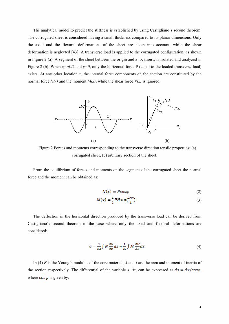
The analytical model to predict the stiffness is established by using Castigliano’s second theorem.
The corrugated sheet is considered having a small thickness compared to its planar dimensions. Only
the axial and the flexural deformations of the sheet are taken into account, while the shear
deformation is neglected [43]. A transverse load is applied to the corrugated configuration, as shown
in Figure 2 (a). A segment of the sheet between the origin and a location x is isolated and analyzed in
Figure 2 (b). When x=nL/2 and y=0, only the horizontal force P (equal to the loaded transverse load)
exists. At any other location x, the internal force components on the section are constituted by the
normal force N(x) and the moment M(x), while the shear force V(x) is ignored.
(a) (b)
Figure 2 Forces and moments corresponding to the transverse direction tensile properties: (a)
corrugated sheet, (b) arbitrary section of the sheet.
From the equilibrium of forces and moments on the segment of the corrugated sheet the normal
force and the moment can be obtained as:
(2)
(3)
The deflection in the horizontal direction produced by the transverse load can be derived from
Castigliano’s second theorem in the case where only the axial and flexural deformations are
considered:
(4)
In (4) E is the Young’s modulus of the core material, A and I are the area and moment of inertia of
the section respectively. The differential of the variable s, ds, can be expressed as ,
where is given by:

6
(5)
The slope of the corrugation is equal to :
(6)
We consider only half of the sinusoid by symmetry. By substituting expressions (2), (3) and (6)
into (4) we obtain:
(7)
The deflection along the horizontal direction produced by the transverse load can be obtained by
calculating the integrals:
(8)
In (8) EK(x) and EE(x) are the first and second kind elliptic integral functions, respectively.
The homogenized linear elastic stress and strain in the corrugated core can be defined as:
(9)
Therefore, the effective transverse Young’s modulus of the corrugated sheet can be expressed
as:
(10)
The transverse stiffness can be formulated as:
(11)
The transverse stiffness of the plate made of the same core material with length L is:

7
(12)
A dimensionless transverse stiffness can be formulated as:
(13)
The SMP fills one side of the corrugation (valley section). The Young’s modulus of the SMP is
dependent on the temperature, and when considering the significant change of stiffness experienced
by the shape memory polymer the analytical model that describes the variable stiffness of the
composite is approximated by considering the thermal variation of the Young’s modulus of the
polymer. When the SMP is heated to a temperature higher than the allowed range limit, its stiffness is
significantly smaller than the one of the corrugated laminate, and therefore the SMP can be treated as
flexible filler. Similarly to the case of filled honeycombs [44-46], the assumption of the analytical
model for the filled composite structure are the following: 1) the valley of the corrugation is entirely
packed by the SMP with a uniform distribution, 2) the material behaviour of the SMP matrix is
considered linear elastic and isotropic, 3) the matrix is perfectly bonded to the corrugated sheet and 4)
the strain distribution in the filler is calculated by considering the corrugated walls as pin-joined
mechanisms (shown in Figure 3 (a) as a red dash line). By inspecting the kinematics of the
deformation shown in Figure 3 (b), for small in-plane strains the corrugated walls can be assumed to
remain straight. The strain in the matrix is therefore uniform and can be calculated as .
(a) (b)
Figure 3 Approximate analysis of variable stiffness corrugation morphing skin: (a) approximate
method, (b) approximated unit of infill.
The additional force caused by the SMP matrix when the corrugated morphing skin undertakes a
transverse deformation can be expressed as:
(14)
The effective transverse stiffness of the SMP filler can be obtained as:

8
(15)
By integrating the internal forces in the corrugated sheet and the SMP matrix in a wavelength we
can obtain the transverse stiffness of the composite corrugated skin:
(16)
In (16), is the Young’s modulus of the shape memory polymer.
2.2 Analytical model of the bending stiffness
The bending stiffness is described by the equivalent flexural modulus of the composite and
its second moment of area . The cross section of the variable stiffness corrugated skin is shown in
Figure 4. When we consider one sinusoidal period the bending stiffness of the composite can be
expressed as:
(17)
In Equation (17) the integrand can be replaced by the expression involving , which has been
derived in the previous section. By performing this substitution and calculating the integral we obtain
the bending stiffness of the corrugated sheet:
(18)
The bending stiffness of the equivalent plate with length L made from the same core
material is:
(19)
Also in this case, we can obtain a dimensionless bending stiffness as:
(20)

9
Figure 4 Cross section of the variable stiffness corrugated skin.
To calculate now the bending stiffness of the corrugated composite with the SMP matrix, we need
first to calculate the neutral axis of the cross section of the SMP filler:
(21)
In most practical applications, the corrugated laminate was made with fibre reinforced plastics
(FRP) [14, 15, 31], the longitudinal Young’s modulus of the corrugated laminate is much higher than
that of SMP, especially when the temperature is above the transformation temperature of SMP. So the
neutral axis of the cross section of the corrugated skin is assumed to be the x-axis, i.e. the same of the
pristine corrugated sheet when neglecting the presence of the SMP matrix. The second moment of
area for the SMP matrix with regard to the x-axis can be expressed as:
(22)
The bending stiffness of the corrugated skin can be therefore formulated as follows:
(23)
The corrugated sheet can be made from various substrates, ranging from metals to composite
materials like woven or unidirectional carbon/glass epoxy [14, 15, 31]. The elastic constants of the
composite laminate can be obtained using classical laminate theory ([A], [B], and [D] matrices) [47].
The stiffness and can be replaced by the terms and respectively in Equation (4),
and the Young’s modulus E can be replaced by the membrane term in Equation (17), where
are corresponding entries in [A] and [D] matrices [47]. The corresponding transverse
and bending stiffness of the composite laminate can be obtained by simple mathematical manipulation.

10
3 Finite element modelling
To validate the analytical models related to the transverse and bending stiffness of the corrugated
composite structures we have performed numerical simulations using a commercial FE (Finite
Element) code (ANSYS, version 15.0, Ansys Inc.). Two specific types of elements have been used,
SHELL181 for the corrugated sheet and SOLID185 for the SMP matrix. The interface between the
corrugated sheet and the SMP was meshed by bonded contact pairs (TARGET170 for the corrugated
shells and CONTACT174 for the shape memory polymer filler). Due to the application of the bonded
contact pair, no sliding or separation between faces is allowed, which supports the simulation of a
perfect bond constraint. After a convergence test the mesh density was fixed at 100 elements per line
of geometric wireframe. The Finite element model of corrugated composite and contact pair between
corrugated laminate and SMP used to calculate the equivalent transverse stiffness were demonstrated
in Figure 5. Two types of parametric simulations were performed to investigate the extreme
mechanical anisotropy and variable stiffness. As for the extreme mechanical anisotropy of corrugated
sheet, the geometric configurations used in the numerical models have a period , thickness
ratios and corrugation ratios ranging between 0.1 and 1 with a
step of 0.05. In these FE models the corrugations are made with ( GPa and Poisson’s ratio
). As for the variable stiffness of corrugated composite with SMP, the property of SMP is
involved in the FE model. The temperature-dependent mechanical properties of the SMP have been
entered via a table. The temperature ranges between 20oC and 150oC with a step 2oC. The geometric
configurations are the same with corrugated sheet except the thickness ratio. The thickness ratio is set
as a constant determined by thickness of carbon fibre prepreg and number of layers. In this part the
corrugated sheet is treated as composite laminate, the material properties of carbon fibre prepreg
T300/epoxy are listed as follows:
.
Corrugated composite laminates with the stacking sequence of [0,90,0] are simulated in FE analysis.
The SMP discussed in this work was an epoxy-based thermoset consisting three parts, the epoxy resin,
the curing agent, and a linear monomer [48]. The material property of SMP infill is temperature
dependent; its elasticity can be investigated by DMA (Dynamic Mechanic Analysis) test. The DMA
was conducted using a dynamic mechanical analyzer (Mettler-Toledo AG Analytical, Switzerland).
The specimen with dimensions of 9.0x3.0x1.0mm3 was performed in three-point bending mode at a
constant heating rate of 5 oC·min-1 and an oscillation frequency of 1 Hz from room temperature 22 oC
to 150 oC. The curves of the storage modulus and the tanδ versus the temperature for the SMP are
plotted in Figure 6. The relationship between the storage modulus and the temperature can be
expressed by a power function as follows:
(24)

11
Where a1=715.5, b1=15.66, c1 =14.16; a2=1359, b2 =37.54 and c2=30.49. The goodness of fit R2=0.99.
Figure 5 Finite element model of corrugated composite and contact pair between corrugated
laminate and SMP used to calculate the equivalent transverse stiffness: (a) and (b) are finite element
model and its zoom in, the blue surface is composite laminate the pink solid is SMP; (c) and (d) are
contact pairs and its zoom in.
Figure 6 Storage modulus and tanδ versus the temperature of the SMP.
The FE models take advantage of the symmetry of the structure, and therefore one sinusoidal
period only is considered as the representative volume element (RVE). The widths of the RVEs, W,
are 10mm and 120mm for the simulations of the transverse and bending stiffness, respectively. The
transverse stiffness is calculated from the simulation of a transverse tensile load, while the flexural
stiffness is obtained by a three points bending test. The boundaries and their conditions are shown in
Figure 7 and Table 1, respectively. In the transverse stiffness analysis, the nodes on line B had
symmetric boundary. The transvers stiffness can be obtained as the ratio between the reaction forces

12
and the imposed displacement. For the analysis related to the bending transverse stiffness the nodes
lying on the lines A and B and on the surface C have symmetric boundary conditions. The bending
stiffness can be derived by using the standard beam theory for cantilever beams [49]. The middle span
deflection can be expressed as and the bending stiffness is therefore obtained as:
(25)
Where F is the reaction force at the boundary C along the 2-direction.
Figure 7 Finite element models of variable stiffness corrugated skin
Table 1 Boundary conditions applied to the FE models to calculate the engineering constants
Boundary Transverse stiffness Bend stiffness
A
B
C Free
D Free
4 Results and discussions
4.1 Anisotropic properties
The relative transverse stiffness vs. the corrugation ratio is shown in Figure 8. The relation
between the relative transverse stiffness and the corrugation ratio is remarkably nonlinear, with a
decrease at higher corrugation ratios H/L, but also featuring an increase for augmenting values of the
thickness ratio t/L. The corrugated sheet tends to provide higher bending deformation for increasing

13
corrugation ratio and decreasing thickness ratios. The bending deformations of the corrugated sheet
result in larger transverse displacement, and therefore lead to a lower relative transverse stiffness. The
relative transverse stiffness obtained by using the FE models shows a very close agreement with the
theoretical predictions. The theoretical predictions show an average relative error with the FE results
equal to 3.3% on average. The results from the FE analysis tend to be slightly higher compared to the
ones from the theoretical investigation. The FE model uses SHELL 181 elements based on Mindlin
plate theory that considers the transverse shear deformations, however the theoretical analysis is based
on adopting simplified Euler-Bernoulli beams that neglect the transverse shear strains. By ignoring
these transverse shears, the theoretical model produces a smaller deformation that results in a higher
transverse stiffness. However, the corrugated sheet can be treated as a thin shell, therefore the
simplification used in developing the theoretical model is sound. The transverse stiffness of
corrugation sheet is 3.8e-5 times lower than the one of the equivalent plate made from the same core
material, and therefore the corrugated structure shows the required low in-plane stiffness to yield large
deformations and minimize actuating forces.
Figure 8 Relative transverse stiffness vs. corrugation ratio for different thickness ratio.
Figure 9 shows the relative bending stiffness vs. the corrugation ratio for different thickness ratios.
Similarly to the relative transverse stiffness, the relation between the relative bending rigidity and the
corrugation ratio is nonlinear. The bend stiffness increases with increasing corrugation ratio H/L, but
decreases for increasing values of thickness ratio t/L. The relative transverse stiffness obtained by
using the FE techniques shows a very close agreement to the theoretical prediction, except for
configurations related to low corrugation and high thickness ratios. When the height is comparable
with thickness the simplification adopted in equation (17) ( ) is not more valid and the
relative error is large. In practical applications the height will be larger than the thickness, so the
theoretical model provides a reasonable accuracy, with an average relative error of 2.1%. The bending
stiffness of the corrugated sheet is 2.6e4 times higher than the one of the equivalent plate made from

14
the same core material, and therefore the corrugated structure possesses the high out-of-plane stiffness
necessary to withstand the aerodynamic pressure load.
Figure 9 Relative bending stiffness vs. corrugation ratio for different thickness ratios.
4.2 Variable stiffness property
The transverse and bending stiffness of the morphing skin with the shape memory polymer at
different temperatures are shown in Figures 10 and 11, respectively. Similarly to the Young’s
modulus of the pristine SMP, the morphing skin is stiff at low temperatures, and becomes flexible
within hotter environments. When the temperature is higher than the SMP transition temperature, both
stiffnesses drop to values similar to the ones of the corrugated laminate without the SMP filler. The
shape memory matrix does not produce however extra stiffness requiring extra actuation energy at
high temperatures, but it contributes to the surface finish for the aerodynamic external flow. The
variations of stiffness increase with the increase of the corrugation ratio. When the corrugated
laminate has a constant period length L, the fraction of the SMP filler increases for increasing
corrugation ratios. It is also apparent that the transverse stiffness is subjected to larger variations and
demonstrates more evident variable stiffness properties compared to the bending one. The transverse
stiffness varies 575 times between 20oC and 150oC, while the bending stiffness is only modified 1.1
times within the same temperature range. As the Young’s modulus of the composite corrugated
laminate is much higher than the one of the SMP the bending stiffness of the morphing skin is
only marginally influenced by the variable Young’s modulus of the SMP filler. It is also worth
noticing that, besides the variable stiffness, the shape memory polymer possesses as well as shape
memory effect, which can lead the morphing skin to freeze the deformed shape as a temporary
configuration and locks the temporary shape without the use of an external force [35, 42].

15
Figure 10 Transverse stiffness vs. the corrugation ratio
Figure 11 Section bending stiffness vs. the corrugation ratio
Weight is an important part of the assessment of the performance of a morphing skin. Figure 12
shows the variation of weight ratios vs. corrugation ratio. In our case we consider two definitions of
weight ratio: one as the ratio between the corrugated composite skin with the SMP filler versus the
one of an aluminum alloy skin with the same bending stiffness of the cross section (Wms/WAl); the
second is the ratio between the weight of the corrugated composite skin with the SMP filler versus the
pure corrugated composite laminate (Wms/WC). For these simulations we consider two corrugated
composite laminates with stacking sequences of [0,90,0] and [0,0,90,0,0]. The mechanical properties

16
are presented in Finite Element modeling section, while the density for the SMP polymer is
considered as 1.58 g/cm3. The material properties of the aluminum alloy consist in a Young’s modulus
of 71GPa, Poisson’s ratio of 0.33 and density of 2.77 g/cm3. It is possible to observe that the weight
ratios increase with the increase of the corrugation ratios. When the corrugated laminate has a
constant period length L, the fraction of the SMP filler increases for increasing corrugation ratios. By
taking advantage of the corrugation structure and the high specific modulus of the composite, the
corrugated composite skin is lighter by around 50% the weight of the aluminum alloy skin with the
same bending stiffness. The corrugated SMP composite skin is however twice as heavy as the pure
corrugated composite laminate.
Figure 12 Weight ratios vs. the corrugation ratio
The comparison between the finite element and the analytical models for the tensile and bending
stiffnesses are shown in Figure 13. The bending stiffness of the morphing skin structure simulated by
the FE and analytical model shows a significant agreement. The tensile stiffness obtained by using the
two models shows however agreement only at high temperatures, and some significant discrepancies
at low temperatures. The analytical model for tensile stiffness was based on the assumption that SMP
can be treated as flexible filler when it is heated to a temperature higher than the allowed range limit,
as state in section 2.1. However, those assumptions are invalid at low temperature, the two models
show some significant discrepancies. The average error between models is about 1.7% for the bending
stiffness, and the maximum one for the tensile stiffness is 375%. The analytical model for tensile
stiffness can therefore be used to obtain approximate values at high temperatures and low Young’s
modulus of the SMP, but a modified model appears to be necessary for more accurate estimations.

17
(a) (b)
Figure 13 Comparison between the finite element and the analytical models: (a) tensile stiffness,
(b) bend stiffness.
Because of the significant change of stiffness generated by the SMP, the analytical model of the
variable stiffness structure can be established for different stiffness ranges. A surface response method
(SRM) has been therefore setup to provide a general design tool for the SMP corrugated morphing
skin. The SRM has been established from the entire data set acquired through the FE and the
analytical models at 1254 different configurations, with stiffness ranges limited to the ratio between
the effective transverse stiffness of SMP filler and the corrugated laminate up to 3. When the stiffness
ratio is lower than that value, the analytical model shows significant agreement with the FE model,
(Figure 14), and the average error is about 1.8%. At stiffness ratios higher than 3 the transverse
stiffness of the morphing skin can be approximate by linking directly the temperature with the
effective transverse stiffness of the corrugated laminate and the SMP filler as:
(26)
The relation is obtained by a least squares fitting (R2=0.98 and 95% confidence level) over
789 configurations, the data set and fitting surface being shown in Figure 15:
(27)
In equation (27), is the corrugation ratio, T is the temperature, and the coefficients are =-1.277,
=8.882e-7, =3.237, =-3.966e-5, =-3.115 and =1.32.

18
Figure 14 Comparison between the finite element and the analytical model for the tensile stiffness
within the stiffness range considered for the SRM
Figure 15 Tensile stiffness of the finite element model and surface fitting beyond the stiffness
range
5 Performance of a variable camber wing skin
The preliminary evaluation of the smart composite corrugated skin structure is performed on a
model representing the upper skin of a variable camber wing concept, which consists of a corrugated
morphing skin, leading and trailing edges, and compliant ribs (Figure 16a). The geometry,
aerodynamic and environmental parameters defining the wing configuration are listed in Table 2. We
consider a NACA 0012 wing section characterized by a rigid D-spar leading edge, which is structure
commonly used to carry global loads [50], and it is widely used in several UAV morphology
evaluations [6, 13]. The chord dimensions used (500 mm) are also compatible with the ones existing
in current UAV wings and helicopter blades (250 mm – 800 mm). The hollow D-spar leading edge
occupies 25% chord, the rigid trailing edge occupies 21% of the chord; both stretch the entire wing

19
span along a rectangular platform. The rigid parts can be fabricated by aluminium alloy or
composites, and thickness depends on the material properties. For the purpose of the skin evaluation
only the upper composite corrugated structure/SMP filler is represented with simply supported
boundary conditions along the edges of the chordwise direction of the skin, and clamped conditions
on the upper and lower sides along the span. The clamps correspond to the regions of the skin
attached to the D-spar and to the section of the trailing edge. The composite corrugates part is
considered being made by carbon fibre T300/914 epoxy (density 1.58 g cm-3, E1 = 73.5 GPa, E2 = 63
GPa, ν12 = 0.055, ν21 = 0.036). The SMP used in these simulations has the same mechanical properties
described in paragraph 3, with a density of 1.18 g cm-3. In the ideal representation of this morphing
wingbox, the aerodynamic pressure on the morphing skin and the trailing edge can be transferred to
the compliant ribs and to the leading edge, which is the main load bearing entity. Because the
feasibility study focuses however on the performance of the corrugated smart morphing skin only, the
particular morphology of the actuator and mechanical performance of the leading and trailing edges
and the compliant ribs are not described, although the interested reader can find related information in
previous works [1, 6, 10]. The simplified representation of Figure 16b may lead to overly
conservative results because it does not take into account the base flexibility provided by the D-spar
and the trailing edge. For the purpose of this evaluation however, the results could be used to
benchmark the actuation authority and performance of the skin versus other smart materials available
in open literature [57].
The deflection and actuation force requirements of the morphing skin at different loading
conditions have been investigated using a FE code code (ANSYS, version 15.0, Ansys Inc.). The
large changes in aerodynamic pressure during morphing have required the use of a sequential coupled
fluid/structure-interaction analysis for the determination of the static equilibrium [51]. The airfoil
shape is built by overlaying the thickness distribution [52] for the NACA 0012 airfoil onto a
parametrically defined camber line. The camber line of the morphing segment of the airfoil is defined
from a third order polynomial shape function, which is suited to describe the shape of the variable
camber morphing wing that relies on compliance or bending of the internal structure [53]. The method
for a parametrically defined airfoil shape has been described in detail by Woods et al [53]. The
trailing edge deflection (TD) was set as 5% and 10% of the chord length. The morphing airfoil shapes
are shown in Figure 17. The aerodynamic pressures were obtained by using the XFOIL lattice panel-
method code, which provides correlated aerodynamic performance predictions with high-fidelity
computational fluid dynamics simulations for the types of smoothly cambered deflected shapes [51].
To improve prediction accuracy, a viscous boundary layer component was involved in XFOIL. The
boundary layer was described by a two-equation lagged dissipation integral boundary layer
formulation with an en transition model [54] (n was set as 9 here according the XFOIL user guide).
The distribution of the pressure coefficient over the different airfoil shapes under different freestream
velocities is shown in Figure 17. The distribution of the pressure coefficient is dominated by the

20
airfoil shape, the larger camber of chord the bigger absolute value of pressure coefficient, which
means (predictably) that the lift performance can be improved by increasing the camber of the chord
efficiently. The resulting aerodynamic pressure P at sea level on the skin surface can then be
calculated from the pressure coefficient. The upper skin carries higher suction loads (indicated by
larger magnitude negative Cp). The FE model representing the upper part of the wing section with the
upper morphing skin was used to verify the stiffness performance of the corrugated smart composite.
As actuation mechanism for the SMP part of the corrugated skin Joule resistive heating could be
considered in conjunction with electrically conductive materials. Corrugations made form continuous
carbon fibres and carbon fibre felt adhesive on the corrugated composite laminates are considered as
promising methods for morphing skin application [37, 55].
(a)
(b)
Figure 16 (a) Variable camber wing concept with the smart composite corrugated structure. (b)
simplified model taking into account the skin only and the aerodynamic loading.
Table 2 Geometrical and analysis parameters
Parameter Value Units
Baseline airfoil NACA 0012 n/a
Span, W 200 mm

21
Chord, C 500 mm
Morphing start 25% C n/a
Morphing segment 56% C n/a
Max Trailing edge deflection, TD [0, 0.05C,0.1C] mm
Angle of attack, α 5 degrees
Freestream velocity, V [0.03:0.1:0.3] Ma
Temperature, T [20:10:150] oC
Reynolds number, Re
n/a
Figure 17 Distribution of pressure coefficient over the different airfoil shape surface under
different freestream velocities from XFOIL. The airfoil shapes depend on the trailing edge (TD)
percentage variations versus the camber (C) at 0 % (0), 5 % (0.05C) and 10 % (0.1C)
The distribution of the pressure coefficient over the airfoil surface obtained from XFOIL was
applied of the FE model to generate the deflection of the morphing skin. The FE model used consists
of 34 representative volume elements (RVE), as shown in Figure 18. The geometrical parameters
have amplitude of 3 mm, period of 8 mm, and width of 200 mm. The corrugated composite laminates
with stacking sequences of [0/90/0] are simulated with shell elements (thickness of 0.375mm). The
elements and material properties are the same as the one used in section 3. The morphing skin is fixed
on the leading and trailing edges, and supported by the compliant ribs. The boundary conditions
applied to the FE models are fixed constraints at the boundaries A and B, with blocked deformations
along the direction 3 of boundary D. The FE models take advantage of the symmetry of the structure,
(1/2 width, and symmetric constraints on boundary C). The aerodynamic pressure from XFOIL was
applied on the top surface of the morphing skin.

22
Figure 18 Finite element model of the smart composite corrugated skin
Figure 19 shows the distribution of the deflections on the upper skin for α=5o, V=0.3Ma, T=120 oC,
TD=0.1C. The normal deflection field correlates with the aerodynamic pressure distribution, with the
maximum deflection occurring at the location of the plane of symmetry close to the leading edge. The
maximum deflection of the upper skin for different conditions (α=5o, V=0.03-0.3Ma, T=20-150 oC,
TD=0, 0.05C and 0.1C.) are shown in Figure 20. The maximum deflection obviously increases with
the increasing velocity, trailing edge initial deflection and temperature. The stiffness of the morphing
skin decreases with increasing temperature, based on the variable stiffness of the SMP. The increasing
pressure load and decreasing stiffness results in an increase of the maximum deflection, which is very
significant when the temperature is over 140 oC. The highest deflection value of 1.87 mm is observed
for TD0.1C at 150 oC. The SMP filler goes into rubber state at significantly higher temperatures than
at its transition temperature. As a result the deformation of the SMP matrix becomes the dominant
parts of the deflection of the morphing skin, and the corrugated composite laminate is not able to
constraint the deflection at an acceptable value. The maximum deflections at 140 oC at a location of
0.001 C are however smaller than 0.5mm (0.001C). According the results obtained by Jacobs [56], the
drag of the airfoil increases only slightly when the skin deflection does not exceed the 0.1% of the
chord. The smart composite corrugated structures appear to provide sufficient stiffness to withstand
the aerodynamic load at low velocities (less than 0.3 Ma) when activated below 140 oC.
Figure 19 The deflection distribution on the upper morphing skin for α=5o, V=0.3Ma, T=120 oC,
TD=0.1C

23
Figure 20 The maximum deflection of the upper morphing skin under different conditions (α=5o,
V=0.03-0.3Ma, T=20-150 oC, TD=0, 0.05C and 0.1C.)
Another quantity evaluated during this feasibility study is the actuation force. The morphing skin
is highly compliant above the SMP transition temperature, a fact that helps to reduce the actuation
force requirements. To provide a change of the variable camber from 5% to 10% of the trailing edge
the upper skin should undergo tensile strains between 1.6% and 4.1%. The actuation forces for two
values of strains have been numerically computed using the same boundary conditions A, C and D of
the previous simulations. The displacements along the 1-direction were 4.29 mm and 11.29 mm,
respectively. The displacement vector sum on the upper morphing skin is shown in Figure 21. The
displacement increases uniformly along the chord, while remaining almost constant along the span.
As the normal deflection field correlates with the aerodynamic pressure distribution (Figure 19), the
ununiform displacement occurs at the location of the plane of symmetry close to the leading edge.
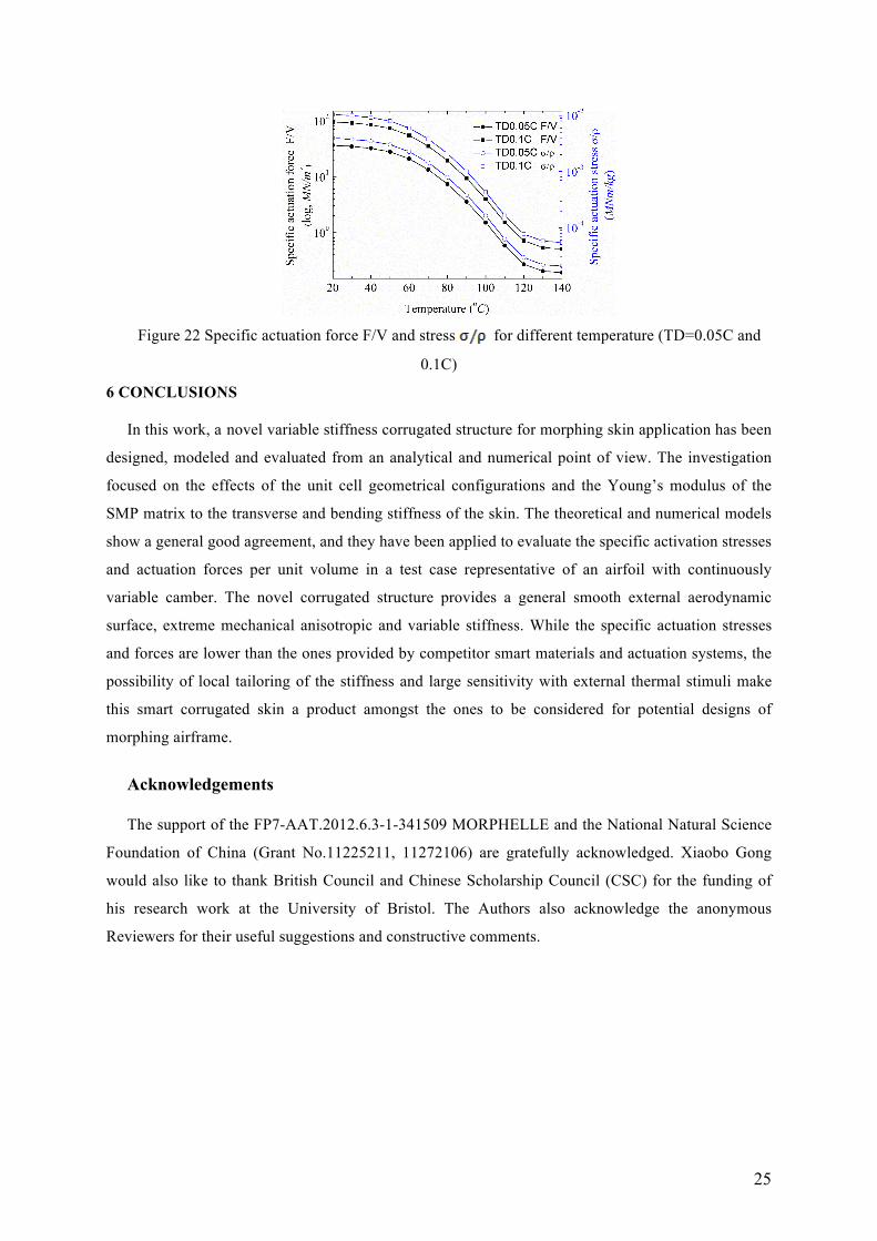
Figure 22 shows the behavior of actuation force per unit volume of the skin (F/V) and the specific
actuation stress σ/ρ at different temperatures. In this case F is the reaction force at the boundary B, σ
is the homogenized linear elastic stress (Equation 9), V is the volume of the SMP fill (V=163.2 cm3)
and ρ is the density of the SMP/carbon corrugated structure (ρ=1.256 kg/m3). The specific actuation
force decreases dramatically with the increasing temperature, dropping from 36.4 MN/m3 and 95.8
MN/m3 to 0.19 MN/m3 and 0.50 MN/m3 within the 20-140 oC. The stiffness of the morphing skin
varies 191 times. Compared with the performance characteristics of the actuator listed by Huber et al
[57], the maximum specific actuation stress occurring at 20 oC is lower than the one featured by shape
memory alloys, hydraulic and magnetostrictive actuators. The minimum specific actuation stress at
140 oC is also lower than the one of pneumatic, muscle and piezoelectric actuators. The variable
stiffness of the SMP skin contributes does contribute to a real time adjustment of the stiffness to offset
varying external conditions. However, when the temperature is higher than the SMP transition the
shape memory matrix does not produce the extra stiffness required for to extra actuation energy, but

24
only contributes to maintain a surface finish for the aerodynamic external flow. At temperatures lower
than the SMP transition the matrix significantly enhances the overall stiffness of the corrugated
composite.
The analysis carried out so far does not include any failure or debonding between the matrix and
the skin, and the effects of brittleness of the SMP at temperatures below the SMP transition (which
would affect the structural integrity of the skin under bending and torsion loads) are not taken into
account. From the operational and systems perspective, it is worth mentioning that the use of shape
memory polymers in a morphing skin is also prone to be subjected to severe constraints. Heating the
polymer is a uniform or local distribution involves a specific design of distributed heaters with
complex distributions and with an additional burden to the power budget of the aircraft. The uniform
heating is also a condition not necessarily met because of the intrinsic difficulties related to the
thermal conduction through the polymer. The exposure of the SMP to UV and solar radiation is also a
factor that affects the cross-linking of the polymer, and therefore its mechanical performance and
structural integrity, also from a fatigue life point of view. Operational conditions like rain, hail and
local convective phenomena do also affect the performance of the polymer, especially its erosion
shield properties. Local thermal gradients and the external airflow can also affect the performance of
the heating process, therefore decreasing the whole actuation authority of the system. Compared to the
pure corrugated composite skin, the additional use of the SMP implies a weight penalty. While the
latter can be minimized by replacing the bulk SMP with shape memory polymer foam and sheet
coatings on the corrugation surface, thicker skins may have a knock-on effect in the overall available
volume for fuel and other subsystems within the wingbox.
Figure 21. Displacement vector sum on the upper morphing skin for α=5o, V=0.3Ma, T=120 oC,
TD=0.1C
25
Figure 22 Specific actuation force F/V and stress for different temperature (TD=0.05C and
0.1C)
6 CONCLUSIONS
In this work, a novel variable stiffness corrugated structure for morphing skin application has been
designed, modeled and evaluated from an analytical and numerical point of view. The investigation
focused on the effects of the unit cell geometrical configurations and the Young’s modulus of the
SMP matrix to the transverse and bending stiffness of the skin. The theoretical and numerical models
show a general good agreement, and they have been applied to evaluate the specific activation stresses
and actuation forces per unit volume in a test case representative of an airfoil with continuously
variable camber. The novel corrugated structure provides a general smooth external aerodynamic
surface, extreme mechanical anisotropic and variable stiffness. While the specific actuation stresses
and forces are lower than the ones provided by competitor smart materials and actuation systems, the
possibility of local tailoring of the stiffness and large sensitivity with external thermal stimuli make
this smart corrugated skin a product amongst the ones to be considered for potential designs of
morphing airframe.
Acknowledgements The support of the FP7-AAT.2012.6.3-1-341509 MORPHELLE and the National Natural Science
Foundation of China (Grant No.11225211, 11272106) are gratefully acknowledged. Xiaobo Gong
would also like to thank British Council and Chinese Scholarship Council (CSC) for the funding of
his research work at the University of Bristol. The Authors also acknowledge the anonymous
Reviewers for their useful suggestions and constructive comments.
26
REFERENCES
[1] Barbarino S, Bilgen O, Ajaj RM, Friswell MI and Inman DJ. A review of morphing aircraft. Journal of Intelligent Material Systems and Structures. 2011;22(9):823-877. [2] Sofla A, Meguid S, Tan K and Yeo W. Shape morphing of aircraft wing: Status and challenges. Materials & Design. 2010;31(3):1284-1292. [3] Jha AK and Kudva JN. Morphing aircraft concepts, classifications, and challenges. Proceedings of SPIE - The International Society for Optical Engineering; 2004. [4] Weisshaar TA. Morphing Aircraft Systems: Historical Perspectives and Future Challenges. Journal of Aircraft. 2007;50(2):337-353. [5] Armando R. Morphing Aircraft Technology Survey. 45th AIAA Aerospace Sciences Meeting and Exhibit; Reno, Nevada, United States: American Institute of Aeronautics and Astronautics; 2007. 2007-1258. [6] Thill C, Etches J, Bond I, Potter K and Weaver P. Morphing skins. The Aeronautical Journal. 2008;112(1129):117-139. [7] Lesieutre GA, Frecker MI, Gandhi FS, Ramrakhyani D, Bharti S, Browne J, et al. Compliant frame: a new paradigm to enable reconfigurable aircraft structures. Air Force Office of Scientific Research, 2007 REPORT No. AFRL-SR-AR-TR-08-0164. [8] Kudva JN. Overview of the DARPA Smart Wing Project. Journal of Intelligent Material Systems & Structures. 2004;15(4):261-267. [9] Kudva JN and Sanders BP. Overview of the DARPA/AFRL/NASA Smart Wing program. Proceeding of SPIE-The Industrial and Commercial Applications of Smart Structures Technologies; 1999. [10] Kudva, J. N, Sanders, B., Pinkertonflorance, J., et al. The DARPA/AFRL/NASA Smart Wing program: Final overview. Proceedings of SPIE-Smart Structures and Materials 2002: Industrial and Commercial Applications of Smart Structures Technologies; 2002. [11] Kudva JN, Appa K, Way CBV and Lockyer AJ. Adaptive smart wing design for military aircraft: requirements, concepts, and payoffs. Proceeding of SPIE-Smart Structures and Materials 1995: Industrial and Commercial Applications of Smart Structures Technologies; 1995. [12] Ramrakhyani DS, Lesieutre GA, Frecker MI and Bharti S. Aircraft Structural Morphing using Tendon-Actuated Compliant Cellular Trusses. Journal of Aircraft. 2005;42(6):1614-1620. [13] Webb LD, Powers SG and Rose LA. Selected Local Flow-Field Measurements on the Advanced Fighter Technology Integration (AFTI)/F-111 Aircraft Mission Adaptive Wing. 1992 REPORT No. NASA-TM-4405. [14] Dayyani I, Shaw AD, Saavedra Flores EI and Friswell MI. The Mechanics of Composite Corrugated Structures: A Review with Applications in Morphing Aircraft. Composite Structures. 2015:358-380. [15] Yokozeki T, Takeda S-i, Ogasawara T and Ishikawa T. Mechanical properties of corrugated composites for candidate materials of flexible wing structures. Composites Part A: Applied Science and Manufacturing. 2006;37(10):1578-1586. [16] Golzar M and Ghabezi P. Corrugated Composite Skins. Mechanics of Composite Materials. 2014;50(2):137-148. [17] Thill C, Etches J, Bond I, Potter K and Weaver P. Corrugated composite structures for aircraft morphing skin applications. 18th International conference of adaptive structures and technologies, Ottawa, Ontario, Canada 2007. [18] Yuying X, Rafic MA and Michael IF. Design and Optimisation of Composite Corrugated Skin for a Span Morphing Wing. 22nd AIAA/ASME/AHS Adaptive Structures

27
Conference; National Harbor, Maryland, United States: American Institute of Aeronautics and Astronautics; 2014. 2014-0762. [19] Dayyani I, Friswell MI, Khodaparast HH and Woods BKS. The design of a corrugated skin for the FishBAC compliant structure. 22nd AIAA/ASME/AHS Adaptive Structures Conference - SciTech Forum and Exposition, January 13, 2014 - January 17, 2014; National Harbor, MD, United states: American Institute of Aeronautics and Astronautics Inc.; 2014. 2014-1121. [20] Navaratne R, Dayanni I, Woods BKS and Friswell MI. Development and testing of a corrugated skin for a camber morphing aerofoil. 23nd AIAA/AHS Adaptive Structures Conference 2015, January 5, 2015 - January 9, 2015; Kissimmee, FL, United states: American Institute of Aeronautics and Astronautics Inc.; 2015. 2015-0792. [21] Dayyani I, Friswell MI, Ziaei-Rad S and Flores EIS. Equivalent models of composite corrugated cores with elastomeric coatings for morphing structures. Composite Structures. 2013;104:281-292. [22] Dayyani I, Friswell MI and Saavedra Flores EI. A general super element for a curved beam. International Journal of Solids and Structures. 2014;51(17):2931-2939. [23] Thill C, Etches JA, Bond IP, Potter KD, Weaver PM and Wisnom MR. Investigation of trapezoidal corrugated aramid/epoxy laminates under large tensile displacements transverse to the corrugation direction. Composites Part A Applied Science & Manufacturing. 2010;41(1):168-176. [24] Ghabezi P and Golzar M. Mechanical analysis of trapezoidal corrugated composite skins. Applied Composite Materials. 2013;20(4):341-353. [25] Dayyani I, Ziaeirad S and Friswell MI. The mechanical behavior of composite corrugated core coated with elastomer for morphing skins. J Compos Mater. 2014;48(13):1623-1636. [26] Previtali F, Arrieta AF and Ermanni P. Double-walled corrugated structure for bending-stiff anisotropic morphing skins. Journal of Intelligent Material Systems and Structures. 2015;26(5):599-613. [27] Previtali F, Molinari G, Arrieta AF, Guillaume M and Ermanni P. Design and experimental characterisation of a morphing wing with enhanced corrugated skin. Journal of Intelligent Material Systems and Structures. 2016;27(2):278-292. [28] Thill C, Downsborough JD, Lai SJ, Bond IP and Jones DP. Aerodynamic study of corrugated skins for morphing wing applications. Aeronautical Journal. 2010;114(1154):237-244. [29] Xia Y, Bilgen O and Friswell MI. The effect of corrugated skins on aerodynamic performance. Journal of Intelligent Material Systems and Structures. 2014;25(7):786-794. [30] Fincham JHS, Ajaj RM and Friswell MI. Aerodynamic performance of corrugated skins for spanwise wing morphing. AIAA AVIATION 2014 -14th AIAA Aviation Technology, Integration, and Operations Conference 2014, June 16, 2014 - June 20, 2014; 2014; Atlanta, GA, United states: American Institute of Aeronautics and Astronautics Inc. [31] Thill C, Etches JA, Bond IP, Potter KD and Weaver PM. Composite corrugated structures for morphing wing skin applications. Smart Materials and Structures. 2010;19(12):124009. [32] Dayyani I, Khodaparast HH, Woods BKS and Friswell MI. The design of a coated composite corrugated skin for the camber morphing airfoil. Journal of Intelligent Material Systems and Structures. 2015;26:1592-1608. [33] Yokozeki T, Sugiura A and Hirano Y. Development of Variable Camber Morphing Airfoil Using Corrugated Structure. Journal of Aircraft. 2014:1-7.

28
[34] Ursache NM, Melin T, Isikveren AT and Friswell MI. Technology Integration for Active Poly-Morphing Winglets Development. ASME 2008 Conference on Smart Materials, Adaptive Structures and Intelligent Systems; 2008; Ellicott City, Maryland, United States. [35] Kuder IK, Arrieta AF, Raither WE and Ermanni P. Variable stiffness material and structural concepts for morphing applications. Progress in Aerospace Sciences. 2013;63(0):33-55. [36] Leng J, Lan X, Liu Y and Du S. Shape-memory polymers and their composites: Stimulus methods and applications. Progress in Materials Science. 2011;56(7):1077-1135. [37] Gong X, Liu L, Liu Y and Leng J. An electrical-heating and self-sensing shape memory polymer composite incorporated with carbon fiber felt. Smart Materials & Structures. 2016;25(3):035036. [38] Keihl MM, Bortolin RS, Sanders B, Joshi S and Tidwell Z. Mechanical properties of shape memory polymers for morphing aircraft applications. Proceedings of SPIE - The International Society for Optical Engineering; 2005. [39] Hemmelgarn CD and Havens E. Adaptive wing structures. Proceedings of SPIE-Smart Structures and Materials 2005: Industrial and Commercial Applications of Smart Structures Technologies; 2005. [40] Sun J, Liu Y and Leng J. Mechanical properties of shape memory polymer composites enhanced by elastic fibers and their application in variable stiffness morphing skins. Journal of Intelligent Material Systems and Structures. 2015;26(15):2020-2027. [41] Bye DR and McClure PD. Design of a morphing vehicle. 48th AIAA Structures, Structural Dynamics, and Materials Conference; Honolulu, Hawaii, United States2007. 2007-1728. [42] McKnight G, Doty R, Keefe A, Herrera G and Henry C. Segmented reinforcement variable stiffness materials for reconfigurable surfaces. Journal of Intelligent Material Systems and Structures. 2010;21(17):1783-1793. [43] Shimansky RA and Lele MM. Transverse Stiffness of a Sinusoidally Corrugated Plate. Mechanics of Structures & Machines. 1995;23(3):439-451. [44] El-Sayed FKA, Jones R and Burgess IW. A theoretical approach to the deformation of honeycomb based composite materials. Composites. 1979;10(4):209-214. [45] Burlayenko VN and Sadowski T. Effective elastic properties of foam-filled honeycomb cores of sandwich panels. Composite Structures. 2010;92(12):2890-2900. [46] Kingnide O and Farhan G. Modeling and Numerical Analyses of Skin Design Concepts. 50th AIAA/ASME/ASCE/AHS/ASC Structures, Structural Dynamics, and Materials Conference; Palm Springs, California, United States: American Institute of Aeronautics and Astronautics; 2009. 2009-2115. [47] Jones RM. Mechanics of composite materials: Scripta Book Company Washington, DC; 1975. [48] Leng J, Wu X and Liu Y. Effect of a linear monomer on the thermomechanical properties of epoxy shape-memory polymer. Smart Materials & Structures. 2009;18(9):7566-7579. [49] Young WC and Budynas RG. Roark's formulas for stress and strain: McGraw-Hill New York; 2002. [50] Woods BKS and Friedrich M. Preliminary investigation of a fishbone active camber concept. ASME 2012 Conference on Smart Materials, Adaptive Structures and Intelligent Systems; September 19-21, 2012; Stone Mountain, Georgia, United States2012. SMASIS2012-8058. [51] Woods BKS, Dayyani I and Friswell MI. Fluid/Structure-Interaction Analysis of the Fish-Bone-Active-Camber Morphing Concept. Journal of Aircraft. 2014:1-13.

29
[52] Moran J. An introduction to theoretical and computational aerodynamics: Courier Corporation; 1984. [53] Woods BK, Fincham JH and Friswell MI. Aerodynamic modelling of the fish bone active camber mophing concept. Proceedings of the RAeS Applied Aerodynamics Conference, Bristol, UK; 2014. [54] Drela M. XFOIL, An Analysis and Design system for Low reynolds Number Airfoils. Conference on Low Reynolds Number Airfoil Aerodynamics, University of Notre Dame; 1989. [55] Kwok N and Hahn HT. Resistance Heating for Self-healing Composites. J Compos Mater. 2007;41(13):1635-1654. [56] Jacobs EN. Airfoil section characteristics as affected by protuberances. Langley Memorial Aeronautical Laboratory: National Advisory Committee For Aeronautics, 1932 REPORT No. 446. [57] Huber JE, Fleck NA and Ashby MF. The selection of mechanical actuators based on performance indices. Proceedings of The Royal Society A: Mathematical, Physical and Engineering Sciences. 1997;453(1965):2185-2205.
Related Documents