Gold Duo Cable Kit January 2014 (Ver. 1.100) www.elmomc.com

Welcome message from author
This document is posted to help you gain knowledge. Please leave a comment to let me know what you think about it! Share it to your friends and learn new things together.
Transcript


|5BCable Kit|www.elmomc.com Table of Contents
Notice
This guide is delivered subject to the following conditions and restrictions:
• This guide contains proprietary information belonging to Elmo Motion Control Ltd. Such information is supplied solely for the purpose of assisting users of the Gold Duo servo drive in its installation.
• The text and graphics included in this manual are for the purpose of illustration and reference only. The specifications on which they are based are subject to change without notice.
• Information in this document is subject to change without notice.
Document no. MAN-G-DUO-CBLKIT (Ver. 1.100) Copyright 2014
Elmo Motion Control Ltd. All rights reserved.
Catalog Number CBL-GDUOKIT01
Revision History
Version Date Details
Ver. 1.0 September 2013 Initial release
Ver. 1.100 January 2014 Initial release with new format

Table of Contents MAN-G-DUO-CBLKIT (Ver. 1.100)
|5BCable Kit|www.elmomc.com
3
Table of Contents
Chapter 1: Introduction .................................................................................................... 4
1.1. Cable Kit .......................................................................................................................... 4
Chapter 2: Feedback Port A Cable (CBL-GPORTA-B2) ......................................................... 5
Chapter 3: Feedback Port B Cable (CBL-GPORTB-B2).......................................................... 7
Chapter 4: Port C & I/O Cable (CBL-GPORTCIO-B2) ............................................................ 9
Chapter 5: STO Cable (CBL-GSTOCOM-B2) ....................................................................... 11

Gold Duo Cable Kit MAN-G-DUO-CBLKIT (Ver. 1.100
www.elmomc.com
4
Chapter 1: Introduction This document provides the wiring details for the cables used to connect Elmo's Gold Duo servo drive with the end-user application. The servo drive-side pinouts are provided in the Gold Duo Digital Servo Drive Installation Guide.
The cables come in one length: 2 meters (6 ½ feet).
1.1. Cable Kit The catalog number of the Gold Duo cable kit is CBL-GDUOKIT01.
NOTE:
It should be noted that this kit does not include any communication cables. Please purchase these cables separately.
This cable kit includes the following cables:
ELMO Part Number Function Quantity
CBL-GPORTA-B2 Feedback port A 2
CBL-GPORTB-B2 Feedback port B 2
CBL-GPORTCIO-B2 Port C and I/O 2
CBL-GSTOCOM-B2 STO 1

Gold Duo Cable Kit MAN-G-DUO-CBLKIT (Ver. 1.100
www.elmomc.com
5
Chapter 2: Feedback Port A Cable (CBL-GPORTA-B2)
The feedback port A cable is made from a 6-pair 24-AWG shielded twisted-pair cable. There is one type of feedback cable, which uses a 12-pin Molex 2.54 mm pitch plug to connect to the servo drive. The part number (P/N) of this cable is CBL-GPORTA-B2.
The feedback port A cable is open on the motor side so that it can be connected to the motor-feedback connector.
The general pinout of the feedback port A cable is as follows:
Pin No.
Signal Color Twisted & Shielded Wire
Plug
1 +5V Brown Pair
12-Pin Molex Plug
2 COMRET White
3 PortA_ENC_A+ Cyan Pair
4 PortA_ENC_A- Orange
5 PortA_ENC_B+ Purple Pair
6 PortA_ENC_B- Black
7 PortA_ENC_INDEX+ Red Pair
8 PortA_ENC_INDEX- Blue
9 HA Green
10 HB Yellow
11 HC Pink
12 PE - Drain Wire
Pin Positions
12-Pin 2.54 mm Pitch Molex
12-Pin Molex Plug

Gold Duo Cable Kit MAN-G-DUO-CBLKIT (Ver. 1.100
www.elmomc.com
6
Note: The specific functionality of each pin is described fully in the Gold Duo Digital Servo Drive Installation Guide.
Figure 1: Single-Sided Main Feedback Cable (Part No. CBL-GPORTA-B2)
Gold Duo Cable Kit MAN-G-DUO-CBLKIT (Ver. 1.100
www.elmomc.com
7
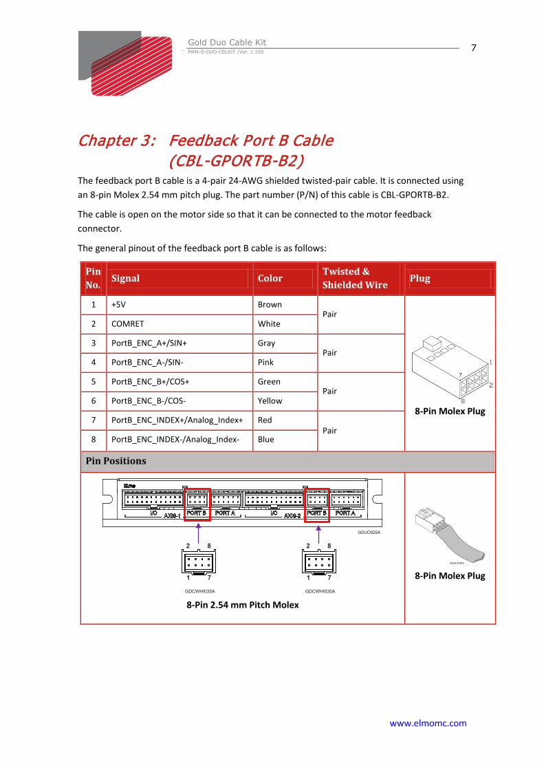
Chapter 3: Feedback Port B Cable (CBL-GPORTB-B2)
The feedback port B cable is a 4-pair 24-AWG shielded twisted-pair cable. It is connected using an 8-pin Molex 2.54 mm pitch plug. The part number (P/N) of this cable is CBL-GPORTB-B2.
The cable is open on the motor side so that it can be connected to the motor feedback connector.
The general pinout of the feedback port B cable is as follows:
Pin No. Signal Color
Twisted & Shielded Wire Plug
1 +5V Brown Pair
8-Pin Molex Plug
2 COMRET White
3 PortB_ENC_A+/SIN+ Gray Pair
4 PortB_ENC_A-/SIN- Pink
5 PortB_ENC_B+/COS+ Green Pair
6 PortB_ENC_B-/COS- Yellow
7 PortB_ENC_INDEX+/Analog_Index+ Red Pair
8 PortB_ENC_INDEX-/Analog_Index- Blue
Pin Positions
8-Pin 2.54 mm Pitch Molex
8-Pin Molex Plug

Gold Duo Cable Kit MAN-G-DUO-CBLKIT (Ver. 1.100
www.elmomc.com
8
Note: The specific functionality of each pin is described fully in the Gold Duo Digital Servo Drive Installation Guide.
Figure 2: Feedback Port B Cable (Part No. CBL-GPORTB-B2)

Gold Duo Cable Kit MAN-G-DUO-CBLKIT (Ver. 1.100
www.elmomc.com
9
Chapter 4: Port C & I/ O Cable (CBL-GPORTCIO-B2) The Port C & I/O cable is a 12-pair 24-AWG shielded twisted-pair cable. It is connected using a 24-pin Molex 2.54 mm pitch plug. The part number (P/N) of this cable is CBL-GPORTCIO-B2.
The cable is open on the motor side so that it can be connected to the controller interface connector.
The general pinout of the Port C and I/O cable is as follows:
Pin No.
Signal Color Twisted & Shielded Wire
Harness (Cable) Plug
1 PortC_ENCO_A+ Brown Pair
ENC_
OU
T
24-Pin Molex Plug
2 PortC_ENCO _A- White
3 PortC_ENCO _B+ Gray Pair
4 PortC_ENCO _B- Pink
5 PortC_ENCO _ Index+ Green Pair
6 PortC_ENCO _ Index- Yellow
7 COMRET Red
8 PE - Shield
9 ANALOG1- Green Pair
INPU
TS
10 ANALOG1+ Yellow
11 ANARET Brown
12 INRET1_6 White
13 IN1 Cyan
14 IN2 Purple
15 IN3 Orange
16 IN4 Black
17 IN5 Pink
18 IN6 Blue
19 OUT4 Brown
OU
TPU
TS 20 OUT3 White
21 OUT2 Gray
22 OUT1 Pink
23 VDD Green Pair
24 VDDRET Yellow

Gold Duo Cable Kit MAN-G-DUO-CBLKIT (Ver. 1.100
www.elmomc.com
10
Pin Positions
24-Pin 2.54 mm Pitch Molex
24-Pin Molex Plug
Note: The specific functionality of each pin is described fully in the Gold Duo Digital Servo Drive Installation Guide.
Figure 3: I/O Cable (Part No. CBL-GPORTCIO-B2)

Gold Duo Cable Kit MAN-G-DUO-CBLKIT (Ver. 1.100
www.elmomc.com
11
Chapter 5: STO Cable (CBL-GSTOCOM-B2) The STO cable is a 26-AWG shielded twisted-pair cable. It is connected using a 3-pin Molex 2.54 mm pitch plug. The part number (P/N) of this cable is CBL-GSTOCOM-B2.
The cable is open on the motor side so that it can be connected to the STO interface connector.
The general pinout of the STO cable is as follows:
Pin No. Signal Color Twisted &
Shielded Wire Plug
1 STO1 Yellow
3-Pin Molex Plug
2 STO2 Green
3 STO_RET White
Pin Positions
3-Pin 2.54 mm Pitch Molex
3-Pin Molex Plug
Figure 4: STO Cable (Part No. CBL-GSTOCOM-B2)
1

Related Documents