User’s Guide Page i 2015 Yakov Polyakov Spreadsheet Solutions 10/30/2015 GoBeam User ’s Guide

Welcome message from author
This document is posted to help you gain knowledge. Please leave a comment to let me know what you think about it! Share it to your friends and learn new things together.
Transcript

User’s Guide Page i
2015
Yakov Polyakov Spreadsheet Solutions 10/30/2015
GoBeam User’s Guide
User’s Guide Page ii
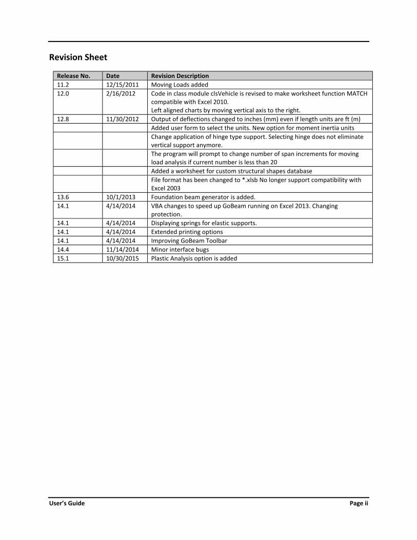
Revision Sheet
Release No. Date Revision Description 11.2 12/15/2011 Moving Loads added 12.0 2/16/2012 Code in class module clsVehicle is revised to make worksheet function MATCH compatible with Excel 2010. Left aligned charts by moving vertical axis to the right. 12.8 11/30/2012 Output of deflections changed to inches (mm) even if length units are ft (m) Added user form to select the units. New option for moment inertia units Change application of hinge type support. Selecting hinge does not eliminate vertical support anymore. The program will prompt to change number of span increments for moving load analysis if current number is less than 20 Added a worksheet for custom structural shapes database File format has been changed to *.xlsb No longer support compatibility with Excel 2003 13.6 10/1/2013 Foundation beam generator is added. 14.1 4/14/2014 VBA changes to speed up GoBeam running on Excel 2013. Changing protection. 14.1 4/14/2014 Displaying springs for elastic supports. 14.1 4/14/2014 Extended printing options 14.1 4/14/2014 Improving GoBeam Toolbar 14.4 11/14/2014 Minor interface bugs 15.1 10/30/2015 Plastic Analysis option is added
User’s Guide Page iii
GoBeam USER'S GUIDE TABLE OF CONTENTS
1. OVERVIEW 1.1 Introduction 1 1.2 Program Capabilities 1 1.3 Program Limitations 2 1.4 Installation and System Requirements 3 1.5 GoBeam Toolbar 5 2. INPUT DATA 2.1 Workbook Organization 7 2.2 General Data 7 2.3 Span Data Table 8 2.4 Support Data Table 9 2.5 Loads Data Table 9 2.6 Managing Loads 10 3. AVAILABLE ANALYSIS TYPES 12 4. MOVING LOAD ANALYSIS 4.1 General 14 4.2 Moving Load Analysis Step-by-Step 14 4.3 Pre-Defined Moving Loads 16 5. PLASTIC ANALYSIS 17 6. SECTION PROPERTIES CALCULATOR 17 7. FOUNDATION BEAM GENERATOR 19 8. OUTPUT OF ANALYSIS RESULTS 19 9. STEP-BY-STEP EXAMPLE 20 APPENDIX A. EXAMPLE OF MOMENT REDISTRIBUTION

User’s Guide Page 1
1. OVERVIEW 1.1 INTRODUCTION GoBeam is a MS Excel based software for the structural analysis of continuous beams with or without columns. While creating GoBeam, the author, a practicing structural engineer, had three goals in mind:
Quick and easy input data allowing rapid, quick, interactive changes Features capable of defining and solving real life engineering problems Full visual and tabulated output for Moment, Shear, Deflection and Rotation
Features GoBeam is a powerful and easy to use beam analysis program. It requires a minimum amount of effort to enter input data and view the results of the analysis. GoBeam has been created in Microsoft Excel spreadsheet; however, all calculations are performed using VBA, which works behind the scenes without cluttering the worksheets. The VBA algorithm employs a finite element analysis using the Displacement Method to find forces and displacements in statically indeterminate structures. The analysis results have been rigorously verified and successfully compared to the results of leading commercial finite element analysis software. 1.2 PROGRAM CAPABILITIES
MODELING Supports SI and US customary units Capable of analyzing continuous beams with up to 100 spans Allows concentrated and linear loads Allows free or fixed ends at the extreme left or right outside supports Handles knife edge or column type supports Capable of elastic supports (vertical springs) Allows hinges (moment release) Allows to model series of simple span beams Allows variable moment of inertia within a span Provides sway frame option (for beams supported on columns)
ANALYSIS 1. Linear static analysis 2. Non-linear analysis of beams on elastic foundation (compression only spring supports) 3. Support settlements analysis 4. Computes influence lines of forces, deflections and support reactions 5. Moving load analysis 6. Plastic analysis
User’s Guide Page 2
PRE AND POST-PROCESSING Saves and restores load cases Combines loads into factored combinations Computes maximum/minimum force envelopes Allows entering formulas into input data fields Convenient tool that calculates and assigns the moment of inertias of typical structural shapes and rolled
steel sections Computes forces and deflections at any location Genuine excel tables allow seamless interface with the user built material design spreadsheets
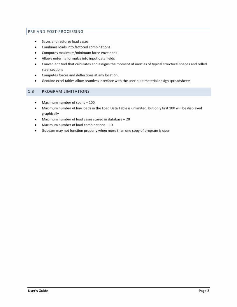
1.3 PROGRAM LIMITATIONS Maximum number of spans – 100 Maximum number of line loads in the Load Data Table is unlimited, but only first 100 will be displayed
graphically Maximum number of load cases stored in database – 20 Maximum number of load combinations – 10 Gobeam may not function properly when more than one copy of program is open

User’s Guide Page 3
1.4 INSTALLATION AND SYSTEM REQUIREMENTS The spreadsheet has been tested to work properly using Microsoft Excel 2007 and 2010 for Windows XP and Windows 7. It’s saved in *.xlsb format, which shall be accessible using Excel 2003 as well (with installed compatibility pack). To install, copy current GoBeam workbook into the working folder on your PC or in a network. The Excel settings must be set to enable VBA macros. In Excel 2007, upon opening of the worksheet the Security Warning will appear in the upper left corner of the screen. Mouse click on Options, then select Enable This Content option on Security Alert Macro dialog box, press OK:
In Excel 2003 set macro security level to medium. Tools/Macro/Security.../Security Level/Medium, press OK:

User’s Guide Page 4
Restart Excel and select Enable Macros option at the prompt:
.

User’s Guide Page 5
1.5 GOBEAM TOOLBAR Most, but not all commands can be executed using command buttons embedded into the worksheets. The toolbar allows access to all commands and helps navigate through the pages of workbook.
In Excel 2007 the toolbar will be found under the Add-Ins tab of the main menu. In Excel 2003 the GoBeam tool bar will appear just below the main menu.
To restore the toolbar, open Macro dialog box (2007: Developer/Macros, 2003: Tools/Macro/Macros…), type ‘CreateMenu’ in the Macro name field and mouse click on ‘Run’ command button:
User’s Guide Page 6
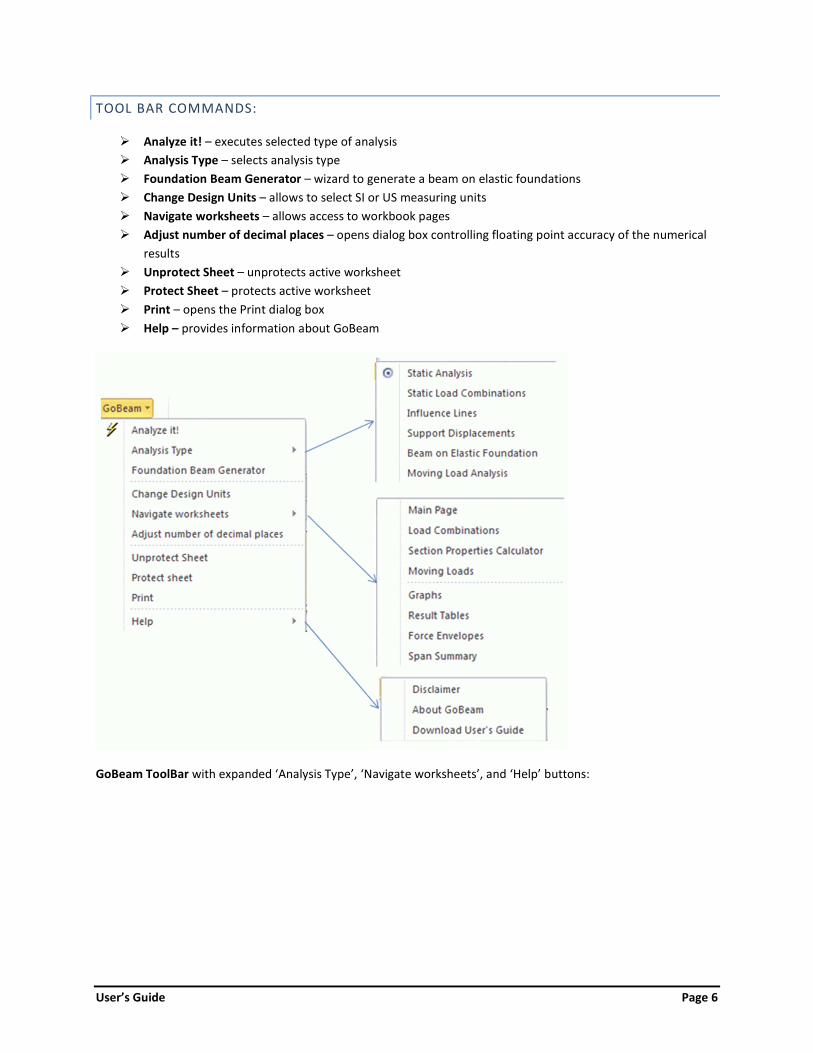
TOOL BAR COMMANDS: Analyze it! – executes selected type of analysis Analysis Type – selects analysis type Foundation Beam Generator – wizard to generate a beam on elastic foundations Change Design Units – allows to select SI or US measuring units Navigate worksheets – allows access to workbook pages Adjust number of decimal places – opens dialog box controlling floating point accuracy of the numerical
results Unprotect Sheet – unprotects active worksheet Protect Sheet – protects active worksheet Print – opens the Print dialog box Help – provides information about GoBeam
GoBeam ToolBar with expanded ‘Analysis Type’, ‘Navigate worksheets’, and ‘Help’ buttons:

User’s Guide Page 7
2. INPUT DATA 2.1 WORKBOOK ORGANIZATION Navigating around the spreadsheet:
Worksheet “Input”, enter beam parameters and loads containing the following data tables: o Span data table o Support data table o Load table
Worksheet “Sections” calculates moment of inertia of various cross-sections and assigns it to spans or to columns.
Worksheet “Results” contains tabulated results for a single load case static analysis or influence lines. Worksheet “Envelopes” contains tables of maximum/minimum force envelopes. Worksheet “Graphs” displays force and displacement diagrams. Worksheet “LoadComb” is used to define load combinations. Worksheet “Trucks” is used to define moving loads.
2.2 GENERAL DATA
Change units (Force: kip, lb, kN, N; Length: ft, in, m, mm; Moment of inertia: in⁴, ft⁴, m⁴, mm⁴)
Select the available US and metric measurement units for force, length and moment of inertia. Modulus of elasticity (ksi, MPa)
Enter separately the modulus of elasticity for the beam(s) and for the column(s). Number of increments per span (1 to 100)
Minimum recommended values are 8 for static analysis and 20 for moving loads analysis. The program will create the specified number of evenly spaced points along the span to report the results. Extra points will be added at the locations of concentrated loads. For spans shorter than half the longest span the number of increments will be reduced proportionally to span length.
Number of spans to display This option formats spreadsheet to allow entering more or less spans. It does not change the number of spans in the model which is defined by the number of properly entered span lengths.
Sway frame This option is applicable to the beams supported by columns. When selected, the frame analysis will allow for lateral displacements, otherwise the model will be restrained from lateral movements.
Beam end restraints Each end of the beam can be either: Free – free to move or rotate (typical cantilever end) Fixed – no rotations allowed. The vertical movement can be allowed by entering spring constant at the vertical spring support line.
User’s Guide Page 8
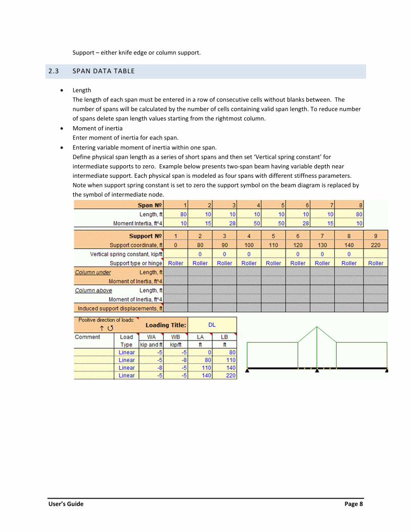
Support – either knife edge or column support. 2.3 SPAN DATA TABLE
Length The length of each span must be entered in a row of consecutive cells without blanks between. The number of spans will be calculated by the number of cells containing valid span length. To reduce number of spans delete span length values starting from the rightmost column.
Moment of inertia Enter moment of inertia for each span.
Entering variable moment of inertia within one span. Define physical span length as a series of short spans and then set ‘Vertical spring constant’ for intermediate supports to zero. Example below presents two-span beam having variable depth near intermediate support. Each physical span is modeled as four spans with different stiffness parameters. Note when support spring constant is set to zero the support symbol on the beam diagram is replaced by the symbol of intermediate node.

User’s Guide Page 9
2.4 SUPPORT DATA TABLE Support type
o Roller – knife edge support with vertical restrain only o Column – provides vertical and rotational restrains. The spring constant KMz = 4EI/L
[force*length/radians], where E – modulus of elasticity, I – moment of inertia, and L – length of the column. Column can be specified below or/and above the beam.
o Hinge – creates moment release in the beam. To remove vertical support set spring constant to zero.
Vertical spring constant Vertical elastic spring can be assigned to roller and column support type or to fixed beam end. Data options:
a. No data in this field corresponds to infinitely stiff vertical support. b. Zero value completely releases vertical restraint at the joint. This option is handy to specify
variable moment of inertia within a span. c. Positive value [Force/Length] creates elastic spring at the joint.
Induced support displacements This line of data is available only for ‘Support Displacements’ type of analysis. Blank cell will be read as zero value.
2.5 LOADS DATA TABLE
Loading Title is an identifier under which load case will be saved in the database. Entering load case data
Each line of data describes a single load. The number of loads is unlimited but only first 100 will be graphically displayed on girder diagram. Empty rows are allowed, the rows with incomplete data are ignored.
Load Types GoBeam permits three load types:
1. Linear – Linearly distributed vertical load. Parameters: WA, WB – load intensity [force/length] on the left and right end respectively. Positive is when acting upward. LA, LB – distance from the left end of the beam to the left and right end of load application.
2. P – Concentrated vertical force. Parameters: WA – load intensity [force]. Positive is when acting upward. LA – distance from the left end of the beam to the load application.
3. M – Concentrated moment. Parameters: WA – load intensity [force*length]. Positive is when acting counter clockwise.

User’s Guide Page 10
LA – distance from the left end of the beam to the load application.
2.6 MANAGING LOADS The load data table can be saved into the database as an independent load case. Later saved load cases can be assembled into the load combinations, and force envelopes. Up to ten load combinations can be specified.
MANAGING INDEPENDENT LOAD CASES Open ’Load Case Manager’ dialog box by using toolbar (GoBeam/Load Combinations) or by ‘Load Combinations’ command button on worksheet ‘Input’. Select tab Independent Loads.
To save current (displayed on worksheet ‘Input’) load case into the database click on command button ‘Save current loading’. The load case will be saved under the name of its Title. Enter a new name in the ‘Loading Name” text box if desired. If load case with this name already exists in the database it will be overwritten.
To restore a saved load case, select its name from the list of Saved Loadings and click on the command button ‘Make Selected Loading Current’. The load case will be restored in the load data table.
To delete load case from database select its name from the list and execute command button ‘Delete Selected Loading’.
User’s Guide Page 11
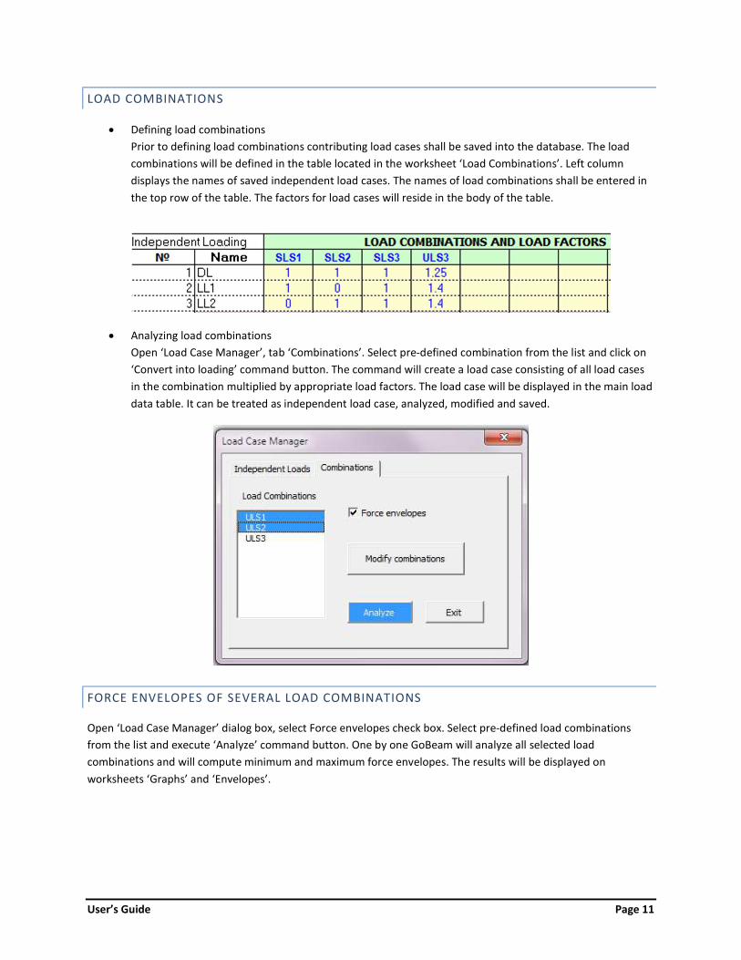
LOAD COMBINATIONS Defining load combinations
Prior to defining load combinations contributing load cases shall be saved into the database. The load combinations will be defined in the table located in the worksheet ‘Load Combinations’. Left column displays the names of saved independent load cases. The names of load combinations shall be entered in the top row of the table. The factors for load cases will reside in the body of the table.
Analyzing load combinations
Open ‘Load Case Manager’, tab ‘Combinations’. Select pre-defined combination from the list and click on ‘Convert into loading’ command button. The command will create a load case consisting of all load cases in the combination multiplied by appropriate load factors. The load case will be displayed in the main load data table. It can be treated as independent load case, analyzed, modified and saved.
FORCE ENVELOPES OF SEVERAL LOAD COMBINATIONS Open ‘Load Case Manager’ dialog box, select Force envelopes check box. Select pre-defined load combinations from the list and execute ‘Analyze’ command button. One by one GoBeam will analyze all selected load combinations and will compute minimum and maximum force envelopes. The results will be displayed on worksheets ‘Graphs’ and ‘Envelopes’.

User’s Guide Page 12
3. AVAILABLE ANALYSIS TYPES The type of analysis can be selected from GoBeam toolbar or from the list box on worksheet ‘Input’.
Static analysis Linear static analysis will be performed for a single load case or for a number of load combinations if force envelopes option is selected (see previous chapter).
Influence lines When this option is selected, the dialog box will prompt to specify section along the beam or a support number for which to construct influence lines of forces and displacements.
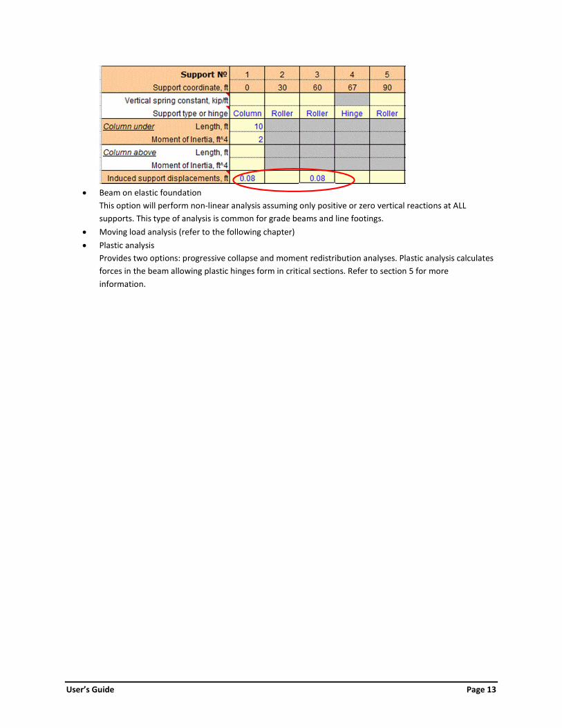
Support displacements This option will compute forces in the beam induced by vertical displacements at the support nodes. The displacements shall be entered in the support data table in the row ‘Induced support displacements’. When support displacements option is selected, the span loads will be ignored. The support displacement cannot be a part of static load combinations.
User’s Guide Page 13
Beam on elastic foundation This option will perform non-linear analysis assuming only positive or zero vertical reactions at ALL supports. This type of analysis is common for grade beams and line footings.
Moving load analysis (refer to the following chapter) Plastic analysis
Provides two options: progressive collapse and moment redistribution analyses. Plastic analysis calculates forces in the beam allowing plastic hinges form in critical sections. Refer to section 5 for more information.

User’s Guide Page 14
4. MOVING LOAD ANALYSIS 4.1 GENERAL The moving loads simulate highway and railroad vehicles. Typically the design codes describe moving load as a combination of truck and/or lane loads. The truck load comprises a sequence of liberally spaced axle (point) loads which can be placed at any location along the beam in order to produce extreme forces. The lane load is a uniform distributed load patterned in a way to contribute to the extreme forces. Gobeam implements influence line based moving load analysis. First it creates force influence lines at each section, analyzes them, and then places moving load in the most unfavorable location. The force due to truck is calculated as FTruck = ∑Piyi, where Pi is a weight of truck ith axle and yi is a value of influence line below that axle. The force due to lane load is calculated as FLane = AowL, where Ao is negative or positive area of influence line and wL is the lane load intensity. The figure below demonstrates sample calculations of maximum bending moment in the midspan section of two-span beam.
Note that precision of computations depends on the number of increments within a beam span (minimum 20 recommended for moving load analysis). 4.2 MOVING LOAD ANALYSIS STEP-BY-STEP.
Step 1. Define beam by filling out span and support data tables. Step 2. Define moving load.
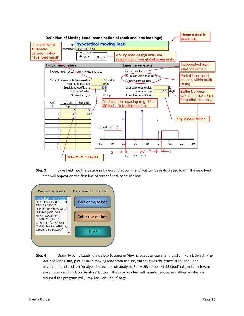
The moving load (combination of truck and lane) must be saved in the database. Access worksheet ‘Trucks’ (Gobeam/Navigate/Moving Loads) and enter moving load parameters as demonstrated below.
User’s Guide Page 15
Step 3. Save load into the database by executing command button ‘Save displayed load’. The new load
title will appear on the first line of ‘Predefined loads’ list box.
Step 4. Open ‘Moving Loads’ dialog box (Gobeam/Moving Loads or command button ‘Run’). Select ‘Pre-
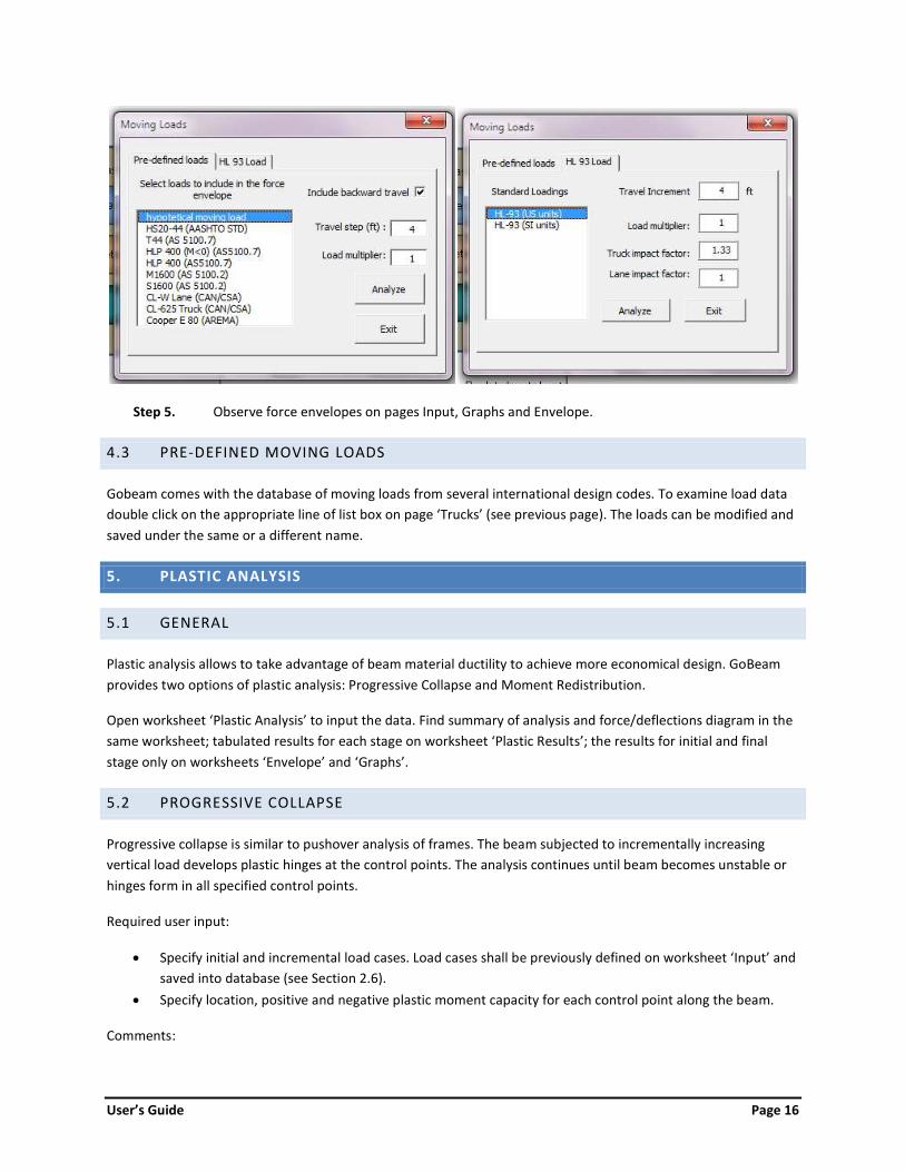
defined loads’ tab, pick desired moving load from the list, enter values for ‘travel step’ and ‘load multiplier’ and click on ‘Analyze’ button to run analysis. For HL93 select ‘HL 93 Load’ tab, enter relevant parameters and click on ‘Analyze’ button. The progress bar will monitor processes. When analysis is finished the program will jump back on ‘Input’ page.
User’s Guide Page 16
Step 5. Observe force envelopes on pages Input, Graphs and Envelope.
4.3 PRE-DEFINED MOVING LOADS Gobeam comes with the database of moving loads from several international design codes. To examine load data double click on the appropriate line of list box on page ‘Trucks’ (see previous page). The loads can be modified and saved under the same or a different name. 5. PLASTIC ANALYSIS 5.1 GENERAL Plastic analysis allows to take advantage of beam material ductility to achieve more economical design. GoBeam provides two options of plastic analysis: Progressive Collapse and Moment Redistribution. Open worksheet ‘Plastic Analysis’ to input the data. Find summary of analysis and force/deflections diagram in the same worksheet; tabulated results for each stage on worksheet ‘Plastic Results’; the results for initial and final stage only on worksheets ‘Envelope’ and ‘Graphs’. 5.2 PROGRESSIVE COLLAPSE Progressive collapse is similar to pushover analysis of frames. The beam subjected to incrementally increasing vertical load develops plastic hinges at the control points. The analysis continues until beam becomes unstable or hinges form in all specified control points. Required user input:
Specify initial and incremental load cases. Load cases shall be previously defined on worksheet ‘Input’ and saved into database (see Section 2.6).
Specify location, positive and negative plastic moment capacity for each control point along the beam. Comments:
User’s Guide Page 17
Use spinner control to see stage by stage changes in forces and displacements. Select ‘Rotations’ on force/displacement diagram to watch rotations in plastic hinges. Plastic hinges may not form in some control points.
5.3 MOMENT REDISTRIBUTION In continuous beams the usual result of moment redistribution is a reduction of negative moments in the support regions and an increase of positive moments between supports compared to the elastic analysis. Moment redistribution relies upon ductility of the regions near support to develop plastic hinges. This method is allowed by most structural codes to achieve more economical designs. Required user input:
Select option to reduce positive or negative moments. Define location of control points where plastic hinges will form and percentage of bending moment
reduction at each location. Specify load case to analyze for. Load case shall be previously defined on worksheet ‘Input’ and saved into
the database (see Section 2.6). Comments:
Moment redistribution is valid only for Ultimate Limit Stage design. No moment redistribution is possible at the support adjacent to the beam overhang. For negative moment reduction define control points directly at support locations. For positive moment reduction define control points between supports, desirably at maximum moment
locations. Note that reduction may not be achieved at all control points. Output is provided for all stages of analysis, but consider only Stage 0 – original elastic forces and Final
Stage – forces after redistribution. An excellent examples of moment redistribution procedures are provided in PCA notes on ACI 318-11.
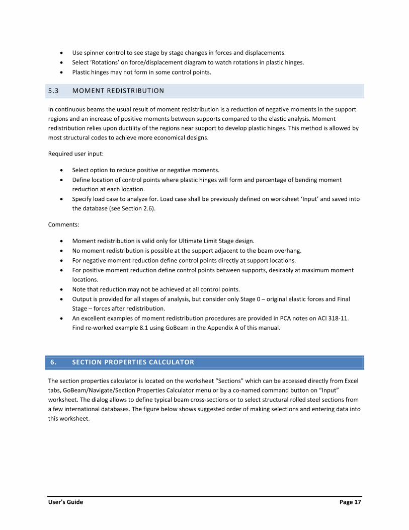
Find re-worked example 8.1 using GoBeam in the Appendix A of this manual. 6. SECTION PROPERTIES CALCULATOR The section properties calculator is located on the worksheet “Sections” which can be accessed directly from Excel tabs, GoBeam/Navigate/Section Properties Calculator menu or by a co-named command button on “Input” worksheet. The dialog allows to define typical beam cross-sections or to select structural rolled steel sections from a few international databases. The figure below shows suggested order of making selections and entering data into this worksheet.
User’s Guide Page 18

User’s Guide Page 19
7. FOUNDATION BEAM GENERATOR This option helps to generate a beam on elastic foundation. It generates a beam with equally spaced elastic supports and calculates their stiffness based on the modulus of subgrade reaction. Open the dialog box using GoBeam toolbar: Add-Ins/GoBeam/Foundation Beam Generator. Selecting ‘Generate new model’ option creates a brand new beam with specified parameters. Choosing ‘Update existing model’ only calculates spring coefficients of elastic supports based on the spans, beam width and modulus of subgrade reaction.
8. OUTPUT OF ANALYSIS RESULTS GRAPHICAL OUTPUT The diagrams of beam forces and displacements due to single load case or maximum/ minimum force envelopes can be viewed on worksheet ‘Graphs’. The worksheet can be accessed through GoBeam toolbar: Add-ins/GoBeam/Navigate/Graphs. TABULATED OUTPUT
The tabulated results of beam forces and displacements due to static analysis and influence line analysis are located on worksheet ‘Results’. The force envelopes of load combinations or moving load analysis are located on page ‘Envelope’.
ANALYSIS RESULTS table lists the values for shear force, bending moment, deflections and rotations at the number of increments within each span specified on worksheet ‘Input’.
ANALYSIS RESULTS AT CUSTOM LOCATIONS table lists forces at the user specified locations entered in the left column. The values at custom locations are calculated by linear interpolation between the values in the ANALYSIS RESULTS table. The section locations can be changed at any time followed by executing “click here to recalculate” command button positioned above the table.
REACTIONS table lists support reactions and support displacements. EXTREME VALUES table lists maximum and minimum forces and displacements in the beam.
Maximum/minimum areas of force diagrams are relevant when Influence Lines type of analysis is selected.
User’s Guide Page 20
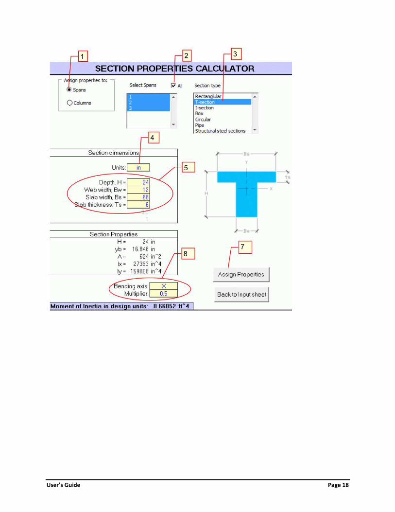
9. STEP-BY-STEP EXAMPLE This example demonstrates analysis of a 3-span reinforced concrete building frame for combinations of dead and live loads. It shows in detail how to build the model, to analyze it for a single load, to create load combinations and to compute envelopes of maximum/minimum forces. Problem: Find maximum/minimum factored forces in reinforced concrete continuous beam due to permanent uniformly distributed load (1.4 kip/ft) and patterned distributed live load (0.6 kip/ft). Parameters:
Spans 28’+24’+28’ Beam is built integrally with columns (top and bottom) Beam is restrained from horizontal displacements Load combination 1.2D+1.6L Beam effective cross-section: T-section, h = 24”, bw = 12”, be = 68”, ts = 6” Columns are 11 feet long, 18”x18” Use gross moment of inertia for columns and cracked moment of inertia for beams (Icr=0.5Ig) Modulus of elasticity for beams and columns E = 3600 ksi
Step-by-step instructions Step 1. Enter beam geometry (refer to Figure 1)
1. Select design units (kip and ft). 2. Enter modulus elasticity for beam and columns (3600 ksi). 3. Set end restraints for left and right ends of the beam to type ‘Support’. 4. Enter length and moment of inertia of each span (I=1.0 for now). 5. Select ‘Column’ type for all 4 supports. 6. Enter column length = 11’ for ‘columns under’ and ‘columns above’. For now, set moment of
inertia for all spans and columns to 1.0. Correct stiffness will be calculated in Step 2.

User’s Guide Page 21
FIGURE 1. WORKSHEET INPUT: SPAN AND SUPPORT DATA TABLES
Step 2. Calculate and assign section properties for beams and columns Access worksheet ‘SECTIONS’ (by selecting sheet tab ‘SECTIONS’, or by clicking on command button ‘SECTION PROPERTIES’, or using menu: ADD-INS/GOBEAM/NAVIGATE/SECTION PROPERTIES CALCULATOR).
Set option button ‘Assign properties to spans’. Select all spans using check box. Make proper selections and fill out data fields in the order shown on Figure 2. Note that multiplier 0.5
accounts for cracked moment of inertia (I = 0.5Ig). Click on the command button ‘Assign Properties’ on the bottom of the page to transfer calculated values of moment of inertia into Span Data table.
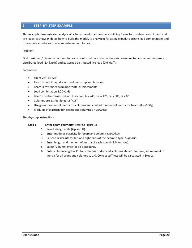
Set option button ‘ASSIGN PROPERTIES TO COLUMNS’. Similarly fill out necessary data (see Figure 3) and execute command button ‘Assign Properties’ to transfer values of column moment of inertia into Support Data table.
Click on command button ‘Back to Input Sheet’. The data tables and model on worksheet ‘Input’ shown on Figure 4.

User’s Guide Page 22
FIGURE 2. WORKSHEET SECTIONS: CALCULATING BEAM MOMENT OF INERTIA.
User’s Guide Page 23
FIGURE 3. WORKSHEET SECTIONS: CALCULATING COLUMN MOMENT OF INERTIA.

User’s Guide Page 24
FIGURE 4. WORKSHEET INPUT: COMPLETED SPAN AND SUPPORT DATA TABLES.
Step 3. Define independent load cases ① Set analysis type to ‘Static Load Analysis’. Now we will define four load cases named D, L1, L2 and L3. The first (D) will be a uniformly distributed dead load (Load Type = Linear) of 1.4 k/ft magnitude (WA = WB = - 1.4) extending over the entire length of the beam (from LA = 0 to LB = 80). ② Enter span load data (it takes a single row in the Load Table). ③ Enter ‘D’ for Load Case Name and ④ click on ‘SAVE DISPLAYED LOAD’ command button to save it into the database. ⑤ Analyze the structure by executing ‘ANALYZE!’ button. ⑥ Select a type of force to display a chart of.
FIGURE 5. WORKSHEET INPUT: INDEPENDENT LOAD CASE ‘D’. Similarly define and save load cases L1, L2 and L3 as shown on Figures 6, 7 and 9 respectively.

User’s Guide Page 25
FIGURE 6. LOAD CASE ‘L1’.
FIGURE 7. LOAD CASE ‘L2’.
FIGURE 8. LOAD CASE ‘L3’.
Step 4. Define load combinations With all independent loads stored we will define load combinations. The load combination table is located on worksheet ‘LoadComb’ which can be accessed via main menu (Add-Ins/GoBeam/Navigate/Load Combinations), using LOAD COMBINATIONS command button (Load Combinations/Modify Combinations), or using Excel page tabs on the bottom of the screen. We’ll define three load combinations: ULS1 = 1.2D+1.6L1 ULS2 = 1.2D+1.6L2 ULS3 = 1.2D+1.6L3 Type in names of load combinations in the first row of the table and enter corresponding load factors of the independent load cases listed on the left. Return to Input worksheet.
FIGURE 9. WORKSHEET LOADCOMB: LOAD COMBINATIONS TABLE. Step 5. Run analysis and review results

User’s Guide Page 26
Open Load Combinations dialog box using command button Load Combinations or via main menu: Add-Ins/Load Combinations. Select tab Combinations. Click on one of the load combinations in the list box. The combination will be converted into independent load case and displayed in Load Table and on the graph. Click on Analyze command button to perform static analysis for single load combination and observe charted results.
Step 6. Calculate force envelopes Open ‘Load Case Manager’ dialog box by clicking on command button ‘Load Combinations’ and select tab ‘Combinations’. Select ‘Force Envelopes’ check box. It will let you select multiple load combinations to be analyzed simultaneously. The resulting forces will be organized into maximum and minimum force envelopes. Select all three load combinations and click ‘Analyze’ button. Wait until analysis completed, it may take a few seconds.
FIGURE 10. LOAD CASE MANAGER DIALOG BOX. Observe force envelope diagrams on the chart. For complete graphical results access worksheet ‘Graphs’ (Add-Ins/GoBeam/Navigate/Graphs), for tabulated results access worksheet ‘Envelope’ (Add-Ins/GoBeam/Navigate/Force Envelopes).

User’s Guide Page 27
FIGURE 11. WORKSHEET GRAPHS: MAXIMUM/MINIMUM FORCE ENVELOPES.
FIGURE 12. WORKSHEET ENVELOPE: FORCE ENVELOPES AT DEFAULT LOCATIONS.

User’s Guide Page 28
To compute results at custom sections enter X-values in the table on Figure 13 and execute ‘recalculate’ button situated above it.
FIGURE 13. WORKSHEET ENVELOPE: RESULTS AT COMPUTED AT USER-DEFINED LOCATIONS.
STEP 7. Refine Model If desired the model can be improved by modeling stiff beam segments within the columns width and assigning foundation springs under the columns. Refer to Figure 12 for changes in geometry. Note that intermediate nodes within a span were added by specifying roller type support with spring constant set to zero.
FIGURE 14. WORKSHEET INPUT: REFINED BEAM MODEL.
Yakov
Stamp
Yakov
Stamp
Yakov
Stamp
Yakov
Text Box
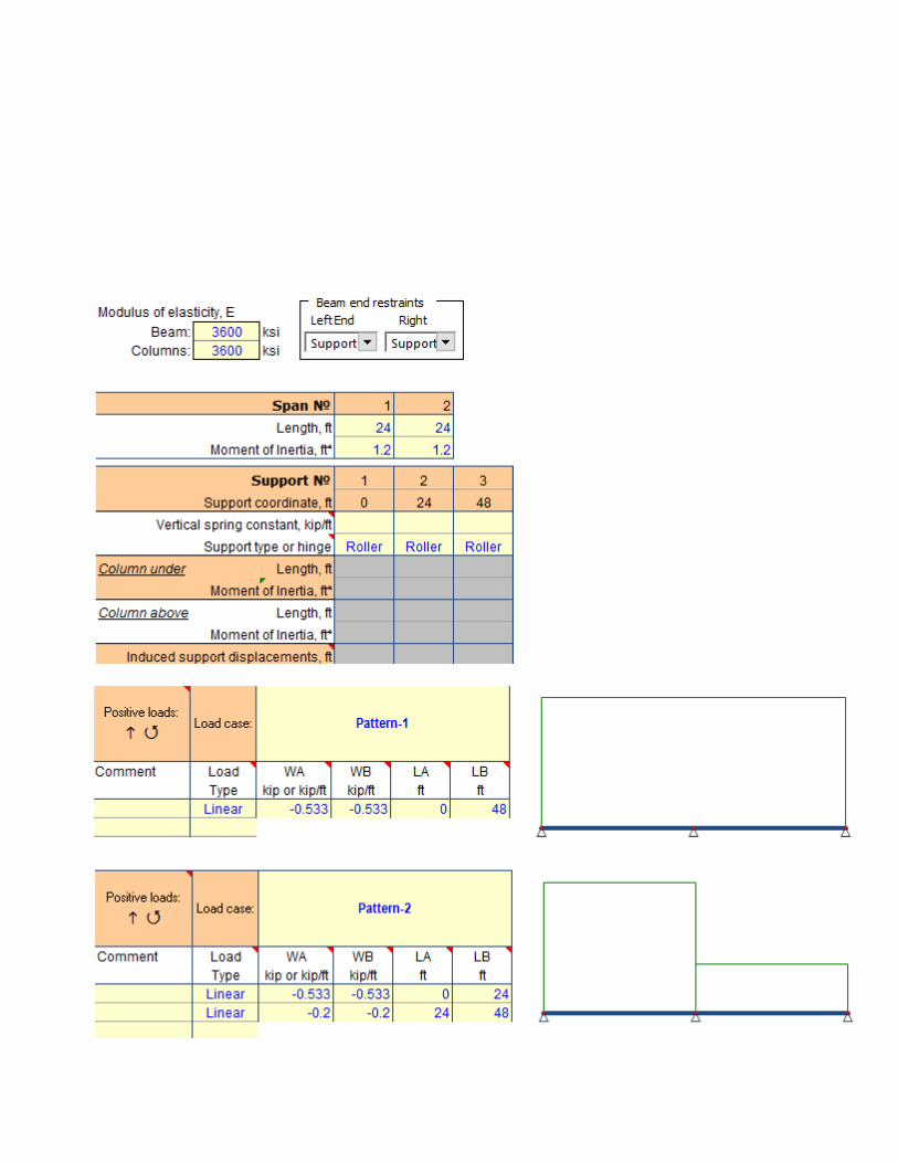
The following is the re-worked Example 8.1 – Moment Redistribution from PCA Notes on ACI 318-11
Yakov
Typewriter
Moment redistribution analysis is performed for two-span continuous slab. Negative moment is reduced by 8.5%, positive moment is reduced by 13.3%. Analysis is performed for two load patterns.
Yakov
Typewriter
1. Setup geometry of the beam 2. Define and save load cases Pattern-1 and Pattern-2

Yakov
Stamp
Yakov
Stamp
Yakov
Typewriter
3. On page Plastic Analysis perorm moment redistribution for load case 'Pattern-1' by reducing negative moment above the central support (X = 24ft) by 8.5%. Note plastic hinge placed by routine in this location.

Yakov
Stamp
Yakov
Stamp
Yakov
Typewriter
4. Repeate moment redistribution for load case 'Pattern-2' by reducing positive moment at X = 9.94ft by 13.3%. Note plastic hinge placed at this location.

Yakov
Stamp
Yakov
Text Box
Final moment envelop after redistribution Negative moment is reduced by 8.5% Positive moment is reduced by 13.3%
Yakov
Typewriter
5. Calculate moment envelope of two moment redisribution analyses. To achieve it the results of final stages for each analysis were copied into separate workbook and moment envelop is calculated using worksheet functions MAX and MIN.
èóë
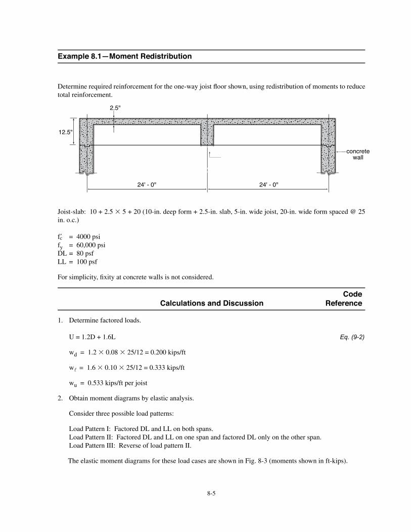
Ü»¬»®³·²» ®»¯«·®»¼ ®»·²º±®½»³»²¬ º±® ¬¸» ±²»ó©¿§ ¶±·¬ A ±±® ¸±©²ô «·²¹ ®»¼·¬®·¾«¬·±² ±º ³±³»²¬ ¬± ®»¼«½»
¬±¬¿´ ®»·²º±®½»³»²¬ò
Ö±·¬ó´¿¾æ ïð õ îòë ë õ îð øïðó·²ò ¼»»° º±®³ õ îòëó·²ò ´¿¾ô ëó·²ò ©·¼» ¶±·¬ô îðó·²ò ©·¼» º±®³ °¿½»¼ à îë
·²ò ±ò½ò÷
� ã ìððð °·
º§ ã êðôððð °·
ÜÔ ã èð °º
ÔÔ ã ïðð °º
Ú±® ·³°´·½·¬§ô B ¨·¬§ ¿¬ ½±²½®»¬» ©¿´´ · ²±¬ ½±²·¼»®»¼ò
Code Calculations and Discussion Reference
ïò Ü»¬»®³·²» º¿½¬±®»¼ ´±¿¼ò
Ë ã ïòîÜ õ ïòêÔ Eq. (9-2)
©¼ ã ïòî ðòðè îëñïî ã ðòîðð µ·°ñº¬
© ã ïòê ðòïð îëñïî ã ðòííí µ·°ñº¬
©« ã ðòëíí µ·°ñº¬ °»® ¶±·¬
îò Ѿ¬¿·² ³±³»²¬ ¼·¿¹®¿³ ¾§ »´¿¬·½ ¿²¿´§·ò
ݱ²·¼»® ¬¸®»» °±·¾´» ´±¿¼ °¿¬¬»®²æ
Ô±¿¼ שּׁ»®² ×æ Ú¿½¬±®»¼ ÜÔ ¿²¼ ÔÔ ±² ¾±¬¸ °¿²ò
Ô±¿¼ שּׁ»®² ××æ Ú¿½¬±®»¼ ÜÔ ¿²¼ ÔÔ ±² ±²» °¿² ¿²¼ º¿½¬±®»¼ ÜÔ ±²´§ ±² ¬¸» ±¬¸»® °¿²ò
Ô±¿¼ שּׁ»®² ×××æ 못®» ±º ´±¿¼ °¿¬¬»®² ××ò
̸» »´¿¬·½ ³±³»²¬ ¼·¿¹®¿³ º±® ¬¸»» ´±¿¼ ½¿» ¿®» ¸±©² ·² Ú·¹ò èóí ø³±³»²¬ ¸±©² ·² º¬óµ·°÷ò
îìù ó ðþ îìù ó ðþ
½±²½®»¬» ©¿´´ïêþ ©·¼» ¹·®¼»®
ïîòëþ
îòëþ
Example 8.1�Moment Redistribution
èóê
CodeExample 8.1 (cont�d) Calculations and Discussion Reference
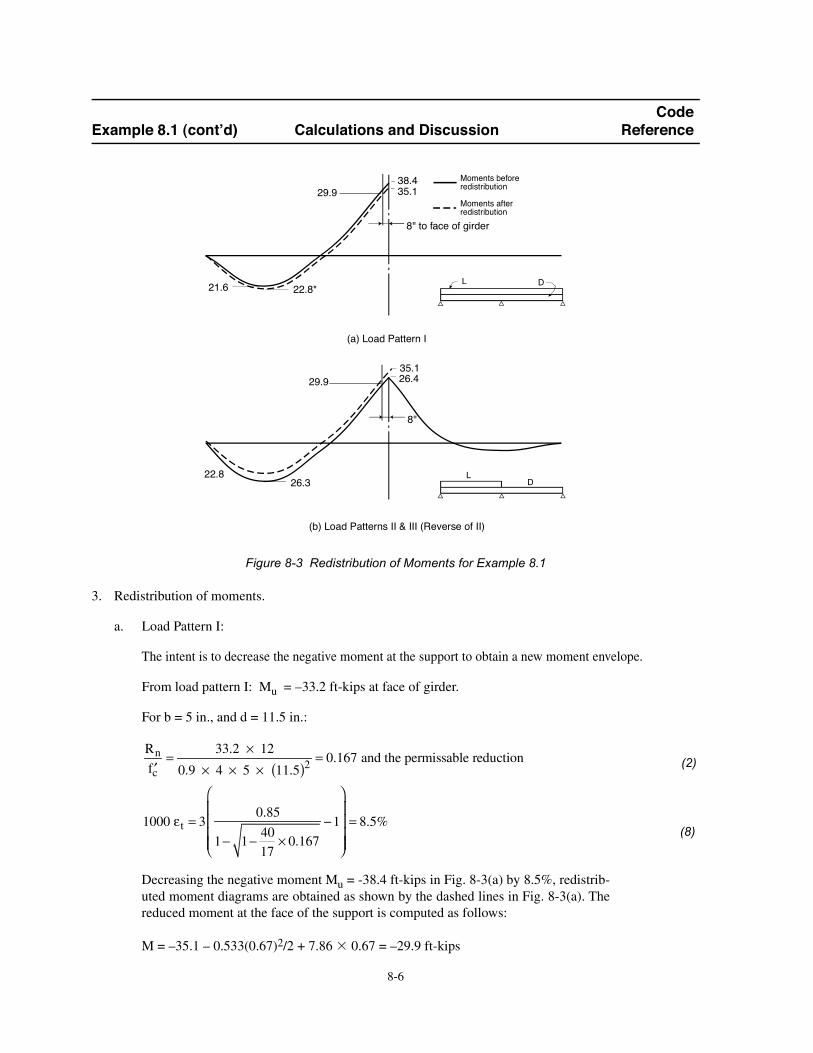
Figure 8-3 Redistribution of Moments for Example 8.1
íò λ¼·¬®·¾«¬·±² ±º ³±³»²¬ò
¿ò Ô±¿¼ שּׁ»®² ×æ
̸» ·²¬»²¬ · ¬± ¼»½®»¿» ¬¸» ²»¹¿¬·ª» ³±³»²¬ ¿¬ ¬¸» «°°±®¬ ¬± ±¾¬¿·² ¿ ²»© ³±³»²¬ »²ª»´±°»ò
Ú®±³ ´±¿¼ °¿¬¬»®² ×æ Ó« ã Pííòî º¬óµ·° ¿¬ º¿½» ±º ¹·®¼»®ò
Ú±® ¾ ã ë ·²òô ¿²¼ ¼ ã ïïòë ·²òæ
β
º½ã
ííòî I ïî
ðòç I ì I ë I ïïòëø ÷îã ðòïêé ¿²¼ ¬¸» °»®³·¿¾´» ®»¼«½¬·±²
ïððð ¬ ã íðòèë
ï� ï�ìð
ïéI ðòïêé
� ï ã èòëû
Ü»½®»¿·²¹ ¬¸» ²»¹¿¬·ª» ³±³»²¬ Ó« ã óíèòì º¬óµ·° ·² Ú·¹ò èóíø¿÷ ¾§ èòëûô ®»¼·¬®·¾ó
«¬»¼ ³±³»²¬ ¼·¿¹®¿³ ¿®» ±¾¬¿·²»¼ ¿ ¸±©² ¾§ ¬¸» ¼¿¸»¼ ´·²» ·² Ú·¹ò èóíø¿÷ò ̸»
®»¼«½»¼ ³±³»²¬ ¿¬ ¬¸» º¿½» ±º ¬¸» «°°±®¬ · ½±³°«¬»¼ ¿ º±´´±©æ
Ó ã Píëòï P ðòëííøðòêé÷îñî õ éòèê ðòêé ã Pîçòç º¬óµ·°
(2)
(8)
ÜÔ
Ó±³»²¬ ¾»º±®»®»¼·¬®·¾«¬·±²
Ó±³»²¬ ¿º¬»®®»¼·¬®·¾«¬·±²
íèòìíëòï
îïòê îîòèö
ø¿÷ Ô±¿¼ שּׁ»®² ×
× × ×
íëòï
îêòí
ø¾÷ Ô±¿¼ שּׁ»®² ×× ú ××× ø못®» ±º ××÷
× × ×
îêòì
îîòè ÔÜ
èþ ¬± º¿½» ±º ¹·®¼»®
îçòç
îçòç
èþ

èóé
CodeExample 8.1 (cont�d) Calculations and Discussion Reference
̸» ³¿¨·³«³ °¿² °±·¬·ª» ³±³»²¬ ½±®®»°±²¼·²¹´§ ·²½®»¿» ¬± îîòè º¬óµ·° ¾§
¿¬·º§·²¹ ¬¿¬·½ »¯«·´·¾®·«³ øÍ»» ½¿´½«´¿¬·±² ·² Ú·¹ò èóì÷ò
Figure 8-4 Maximum Positive Moment after Redistribution for Load Pattern I
¾ò Ô±¿¼ שּׁ»®² ××æ
̸» ·²¬»²¬ · ¬± ¼»½®»¿» ¬¸» °±·¬·ª» ³±³»²¬ ²»¿® ³·¼°¿² ¬± ±¾¬¿·² ¿ ²»© ³±³»²¬ »²ª»´±°»ò
̸» »´¿¬·½ ³±³»²¬ ¼·¿¹®¿³ ±º Ô±¿¼ שּׁ»®² ×× · ½±³°¿®»¼ ©·¬¸ ¬¸» ®»¼·¬®·¾«¬»¼ ³±ó
³»²¬ ¼·¿¹®¿³ ±º Ô±¿¼ שּׁ»®² ×ò Ú±® ¿ª·²¹ ·² °¿² °±·¬·ª» ³±³»²¬ ®»·²º±®½»³»²¬ô
·¬ · ¼»·®¿¾´» ¬± ®»¼«½» ¬¸» °¿² °±·¬·ª» ³±³»²¬ ±º îêòí º¬óµ·°ò
Ú±® ¾ ã îë ·²ò ø¬®» ¾´±½µ ©·¬¸·² A ¿²¹»÷ô ¿²¼ ¼ ã ïïòë ·²ò
β
º½ã
îêòí I ïî
ðòç I ì I îë I øïïòë÷î ã ðòðîé
ïððð ¬ ã íðòèë
ï� ï�ìð
ïéI ðòðîé
� ï ã ééòëû â îðû
л® èòìô ³¿¨·³«³ °»®½»²¬ ®»¼·¬®·¾«¬·±² · ´·³·¬»¼ ¬± îðûò ̸» ½±³°«¬»¼ ®»¼·¬®·¾«¬·±² °»®½»²¬
· ª»®§ ¸·¹¸ò ׬ · ·²¼·½¿¬·ª» ±º ¿ ¸·¹¸ ²»¬ ¬»²·´» ¬®¿·²ô ©¸·½¸ ®»A »½¬ ¿ ³¿´´ ®»·²º±®½»³»²¬ ·²¼»¨ò
ß ²±¬»¼ ·² ¬¸» º±±¬²±¬» ¬± Ì¿¾´» èóïô Ó·²·³«³ A »¨«®¿´ ®»·²º±®½»³»²¬ · ®»¯«·®»¼ º±® ¬¸» °¿²
°±·¬·ª» ³±³»²¬ò
̸» »´¿¬·½ ³±³»²¬ ¼·¿¹®¿³ ±º Ô±¿¼ שּׁ»®² ×× · ½±³°¿®»¼ ©·¬¸ ¬¸» ®»¼·¬®·¾«¬»¼ ³±³»²¬
¼·¿¹®¿³ ±º Ô±¿¼ שּׁ»®² ×ò Ú±® ¿ª·²¹ ·² °¿² ³±³»²¬ ®»·²º±®½»³»²¬ô ·¬ · ¼»·®¿¾´» ¬± ®»¼«½» ¬¸»
°¿² °±·¬·ª» ³±³»²¬ ±º Ô±¿¼ שּׁ»®² ×× º®±³ îêòí º¬óµ·° ¬± îîòè º¬óµ·°ô ·ò»ò ïíòíû ®»¼·¬®·¾«¬·±²ò
ìò Ü»·¹² º¿½¬±®»¼ ³±³»²¬ò
Ú®±³ ¬¸» ®»¼·¬®·¾«¬»¼ ³±³»²¬ »²ª»´±°»ô º¿½¬±®»¼ ³±³»²¬ ¿²¼ ®»¯«·®»¼ ®»·²º±®½»³»²¬ ¿®»
¼»¬»®³·²»¼ ¿ ¸±©² ·² Ì¿¾´» èóïò
ìòçíµ éòèêµ
íëòïùµ
îìùóðþ
ðòëííµñº¬
¨
Ê ã ðਠã çòîë º¬
Óਠã çòîë º¬ ã ìòçí I çòîëø ÷� ðòëíí I çòîëî
î
ã îîòèùµ

èóè
CodeExample 8.1 (cont�d) Calculations and Discussion Reference
Table 8-1 Summary of Final Design
Ý¿´½«´¿¬» º±® A ¿²¹»¼ ³»³¾»®ò Í»» ﮬ éò
Ú·²¿´ ²±¬»æ Ó±³»²¬ ®»¼·¬®·¾«¬·±² ¸¿ °»®³·¬¬»¼ ¿ ®»¼«½¬·±² ±º èòëû ·² ¬¸» ²»¹¿¬·ª»
³±³»²¬ ¿²¼ ¿ ®»¼«½¬·±² ±º ïíòíû ·² ¬¸» °±·¬·ª» ³±³»²¬ò
Load Pattern Required Steel Provided Steel
Section I II As (in.2) As (in.2) **Redistribution,
percent
SupportMoment*(ft-kips)
-29.9 � 0.64 0.0111 2-No.6 0.0153(b = 5 in.)
MidspanMoment(ft-kips)
� 22.8 0.45 0.0016 1-No. 70.0036***
(b = 25 in.)
*Calculated at face of support.
**Check min = = 0.0032
min = 200
60,000 = 0.0033 (governs)
*** = A
b d =
1.04
25 11.5= 0.0036 > s
w mi n
×
-8.5
-13.3
(0.88)
(1.04)
1-No.6
Related Documents