Goal-Oriented Design of Domain Control Panels Christophe Ponsard 1 , Nadiya Balych 2 , Philippe Massonet 1 , Jean Vanderdonckt 2 , and Axel van Lamsweerde 2 1 CETIC Research Center, Charleroi, Belgium 2 Universit´ e Catholique de Louvain, Belgium Abstract. Goal-oriented methodologies have demonstrated some adequacy for modelling composite systems, from high level desired properties to operational requirements on responsible agents. This paper shows how to derive a user inter- face for human agents from such a model, especially with respect to the monitor and control capabilities of those agents. A goal-oriented widget taxonomy was elaborated in order to facilitate selecting widgets that are appropriate for each element of the underlying domain model. A user-friendly tool for building user interfaces, supporting the retrieval of adequate components and their fine tuning at a graphical level, was developed and deployed on the animator of the Objec- tiver/FAUST requirements toolbox. 1 Introduction For many years, Model-Based Interface Development Environments (MB-IDEs) have been largely driven and inspired by the same suite of typical models such as: task, do- main, user, abstract user interface, concrete user interface, final user interface, platform, etc. [17][2]. Among these, two classic models typically initiate the development pro- cess: the domain and task models. The former has been largely used during the past decade to automatically generate a graphical user interface. The later was defined to ad- dress some shortcomings. Today, it represents the most common model that drives the development process to foster user-centered design. These models have demonstrated some relevance, some convenience, and some efficiency in producing user interfaces for a very specific type of interactive system: information systems, where the User Inter- face (UI) mainly consists of a predefinition of forms, windows, menu bars, pull-down menus, etc. Typical information systems could be developed in Interface Builders such as Microsoft Visual Basic, C++, Java or Web applications. Traditional MB-IDEs have demonstrated the feasibility of the approach for such systems. But when it comes to developing the UI of a complex, reliable system that is not an information system (e.g., a control system, a simulator), in particular when the UI can- not consist of predefined widgets with a predefined behavior, it seems more difficult to reuse the same suite of models. Since in this case these models have not been expanded enough to capture sufficient information to initiate the development process, perhaps other models need to be used. In addition, the task model is widely recognized and used in the Human-Computer Interaction (HCI) community, whereas the Software Engineering (SE) and more specif- ically Requirements Engineering (RE) community, tends to ignore such a model and S.W. Gilroy and M.D. Harrison (Eds.): DSVIS 2005, LNCS 3941, pp. 249–260, 2006. c Springer-Verlag Berlin Heidelberg 2006

Welcome message from author
This document is posted to help you gain knowledge. Please leave a comment to let me know what you think about it! Share it to your friends and learn new things together.
Transcript
Goal-Oriented Design of Domain Control Panels
Christophe Ponsard1, Nadiya Balych2, Philippe Massonet1,Jean Vanderdonckt2, and Axel van Lamsweerde2
1 CETIC Research Center, Charleroi, Belgium2 Universite Catholique de Louvain, Belgium
Abstract. Goal-oriented methodologies have demonstrated some adequacy formodelling composite systems, from high level desired properties to operationalrequirements on responsible agents. This paper shows how to derive a user inter-face for human agents from such a model, especially with respect to the monitorand control capabilities of those agents. A goal-oriented widget taxonomy waselaborated in order to facilitate selecting widgets that are appropriate for eachelement of the underlying domain model. A user-friendly tool for building userinterfaces, supporting the retrieval of adequate components and their fine tuningat a graphical level, was developed and deployed on the animator of the Objec-tiver/FAUST requirements toolbox.
1 Introduction
For many years, Model-Based Interface Development Environments (MB-IDEs) havebeen largely driven and inspired by the same suite of typical models such as: task, do-main, user, abstract user interface, concrete user interface, final user interface, platform,etc. [17][2]. Among these, two classic models typically initiate the development pro-cess: the domain and task models. The former has been largely used during the pastdecade to automatically generate a graphical user interface. The later was defined to ad-dress some shortcomings. Today, it represents the most common model that drives thedevelopment process to foster user-centered design. These models have demonstratedsome relevance, some convenience, and some efficiency in producing user interfaces fora very specific type of interactive system: information systems, where the User Inter-face (UI) mainly consists of a predefinition of forms, windows, menu bars, pull-downmenus, etc. Typical information systems could be developed in Interface Builders suchas Microsoft Visual Basic, C++, Java or Web applications. Traditional MB-IDEs havedemonstrated the feasibility of the approach for such systems.
But when it comes to developing the UI of a complex, reliable system that is not aninformation system (e.g., a control system, a simulator), in particular when the UI can-not consist of predefined widgets with a predefined behavior, it seems more difficult toreuse the same suite of models. Since in this case these models have not been expandedenough to capture sufficient information to initiate the development process, perhapsother models need to be used.
In addition, the task model is widely recognized and used in the Human-ComputerInteraction (HCI) community, whereas the Software Engineering (SE) and more specif-ically Requirements Engineering (RE) community, tends to ignore such a model and
S.W. Gilroy and M.D. Harrison (Eds.): DSVIS 2005, LNCS 3941, pp. 249–260, 2006.c© Springer-Verlag Berlin Heidelberg 2006
250 C. Ponsard et al.
rather prefer to exploit models that are more traditionally used in their field. This pa-per investigates whether the shortcomings of most MB-IDEs for complex, reliable,time constrained interactive systems could be developed following a model-based ap-proach, but based on another suite of models than those which are traditionally usedin HCI.
In particular, the task model usually represents in HCI the user’s viewpoint by recur-sively decomposing the task into sub-tasks that are connected with temporal operatorsto end up with leaf tasks. Of course, each task is associated with one or several goalsthat need to be achieved when the task has been carried out. In contrast, in RE, a goalmodel represents the system’s viewpoint by specifying a decomposition of goals intosub-goals that are linked together with several operators to end up with leaf goals as-signed to an agent.
As in HCI, the initial goal model does not come alone. It is then related to threeother models that progressively capture relevant information for the other aspects: ob-ject model, agent model, and operation model (Sect. 2). These models are frequentlyused in the area of RE which provides capabilities to reason about human agent inter-face design with respect to the requirements under its responsibility (Sect. 3). Therefore,when it comes to specifying the components of the final user interfaces, i.e. the widgetsto be used, instead of having a widget classification that is based on the task and/or thedomain, the widget ontology should also be revisited. It should provide a rich frame-work to select the most appropriate combination of displays/controls for each agent torealize its goals (Sect. 4). Then, an animator should provide agent-oriented animationsin the same way as the task can be simulated in traditional MB-IDEs [14][1] (Sect. 5).Finally, related work will be reviewed to highlight the contribution and limitations ofour approach.
Throughout this paper, a non-trivial train system will be used as running example.Although simplified for fitting the size constraints of this paper, this system is based onimplementations taken from real world railway signaling systems.
2 Background: Goal-Oriented Modeling
This paper considers goal-oriented modelling with the KAOS language which is organ-ised in 4 models: (i) the central model is the goal model which captures and structuresthe assumed and required properties; (ii) the object model captures the relevant vocab-ulary to express the goals; (iii) the agent model takes care of assigning goals to agentsin a realizable way; (iv) the operation model details, at state transitions level, the workan agent has to perform to reach the goals he is responsible for.
2.1 Building the Goal and the Object Models
Although the process of building those 4 models is intertwined, the starting point isusually a number of key properties of the system to-be. Those are expressed usinggoals which are statements of intent about some system (existing or to-be) whose sat-isfaction in general requires the cooperation of some of the agents forming that system.Agents are active components, such as humans, devices, legacy software or software-to-be components, that play some role towards goal satisfaction. Some agents thus define
Goal-Oriented Design of Domain Control Panels 251
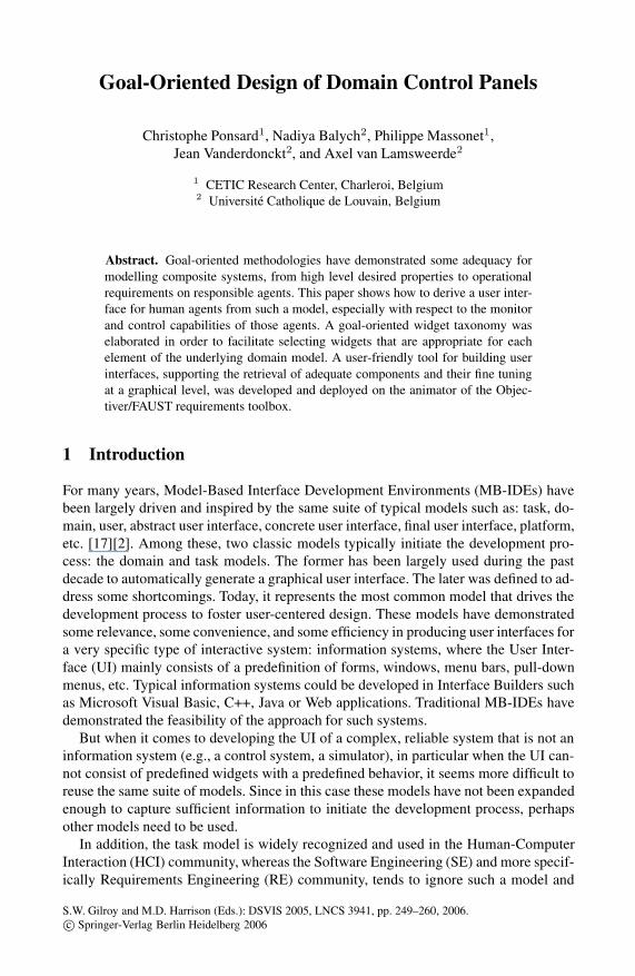
Fig. 1. Object Model
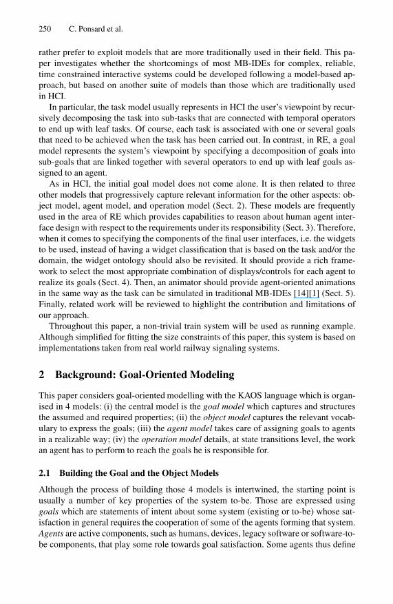
Fig. 2. Portion of the Goal graph
the software whereas the others define its environment. Goals may refer to services to beprovided (functional goals) or to the quality of service (non-functional goals). Goals aredescribed informally in natural language (InformalDef) and are optionally formalizedin a real-time temporal logic (FormalDef) [3][8][12].
In our example, the goals relate to safety of transportation: avoiding collision be-tween trains, with other vehicles (especially at railroad crossings), securing passenger(eg., by closing doors when moving). This goal can be stated as follows:
Goal Maintain[DoorsClosedWhileMoving]InformalDef: Doors should be closed when the train is moving.FormalDef: (∀tr : Train) tr.moving ⇒ tr.doorClosed
In the above formulation, we have identified the Train entity with its moving anddoorClosed attributes. Those are incrementally added to the structural model whichcaptures passive (entities, relationships and events) and active objects (agents).
Unlike goals, domain properties are descriptive statements about the environment,such as physical laws, organizational norms or policies, etc. (eg., a train requires somedistance to come to stop—law of inertia).
A key characteristic of goal-oriented requirements engineering is that goals are struc-tured and that guidance is provided to discover that structure and refine it until agentscan be found to realize those goals in cooperation. In KAOS, goals are organized inAND/OR refinement-abstraction hierarchies where higher-level goals are in general
252 C. Ponsard et al.
strategic, coarse-grained and involve multiple agents whereas lower-level goals are ingeneral technical, fine-grained and involve fewer agents [4]. In such structures, AND-refinement links relate a goal to a set of subgoals (called refinement) possibly conjoinedwith domain properties; this means that satisfying all subgoals in the refinement is asufficient condition in the domain for satisfying the goal. OR-refinement links may re-late a goal to a set of alternative refinements.
Figure 2 shows the goal structure for our system. It was set up starting from a fewinitial goals and by asking respectively ”WHY” and ”HOW” questions to discoverparent goals (such as Maintain[SafeTransportation]) and son goals (such as Main-tain[DoorClosedWhileMoving]).
2.2 The Agent Model
Goal refinement ends when every subgoal is realizable by some individual agent as-signed to it, that is, expressible in terms of conditions that are monitorable and con-trollable by the agent [10]. A requirement is a terminal goal under responsibility of anagent in the software-to-be; an expectation is a terminal goal under responsibility of anagent in the environment. For example:
Agent TrainDriverKind: HumanResponsibleFor: Maintain[DoorClosedWhileMoving], Achieve[TrainProgress...Monitors: Block.signalControls: Train.moving, Train.doorClosed, Train.blockOf
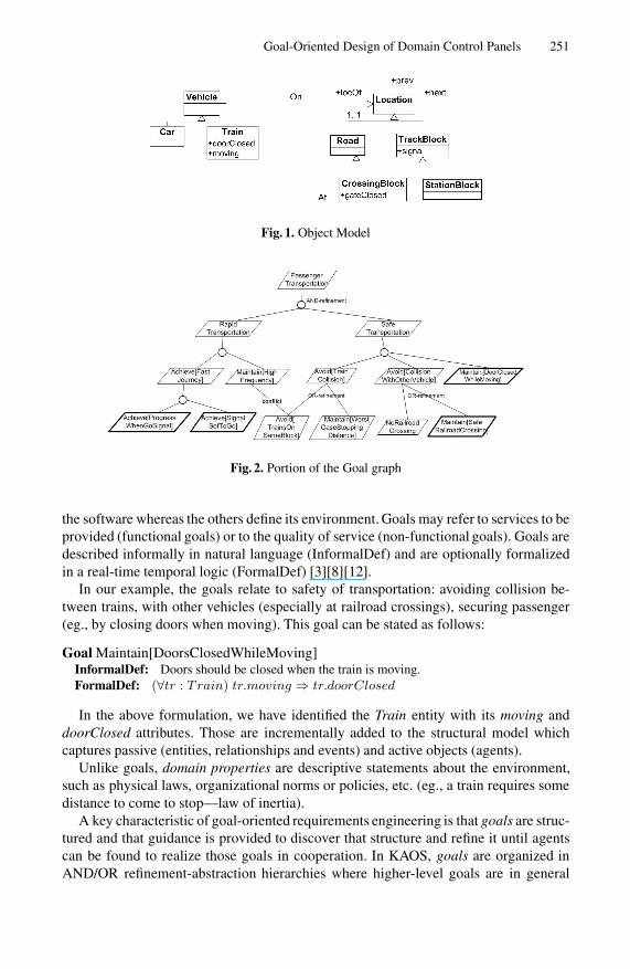
In our design, all agents are part of the automated system except the train driver,a human which stays in control of the moving state and the location of the train. Thedoor and motor controllers are running on board of the train, while the signal con-troller and the gate controller are ground-based. In our case study, a very importantproblem to reason about is the way to relay ground and board information w.r.t theirmonitor/control needs. Figure 3 shows the agent interface view which displays the flowof monitored/controlled information among agents.
Fig. 3. Agent Interface Model
2.3 The Operation Model
Goals are operationalized into specifications of operations to achieve them [3]. Anoperation is an input-output relation over objects; operation applications define state
Goal-Oriented Design of Domain Control Panels 253
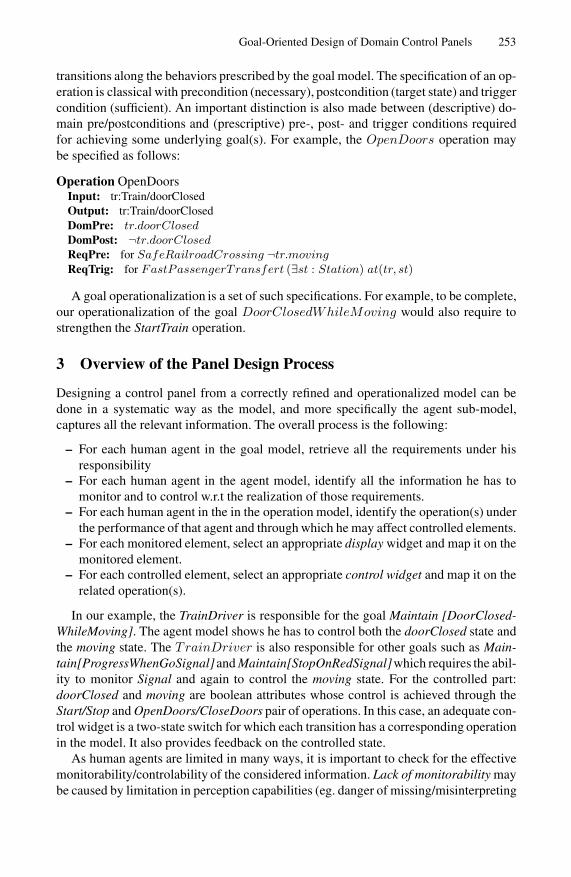
transitions along the behaviors prescribed by the goal model. The specification of an op-eration is classical with precondition (necessary), postcondition (target state) and triggercondition (sufficient). An important distinction is also made between (descriptive) do-main pre/postconditions and (prescriptive) pre-, post- and trigger conditions requiredfor achieving some underlying goal(s). For example, the OpenDoors operation maybe specified as follows:
Operation OpenDoorsInput: tr:Train/doorClosedOutput: tr:Train/doorClosedDomPre: tr.doorClosedDomPost: ¬tr.doorClosedReqPre: for SafeRailroadCrossing ¬tr.movingReqTrig: for FastPassengerTransfert (∃st : Station) at(tr, st)
A goal operationalization is a set of such specifications. For example, to be complete,our operationalization of the goal DoorClosedWhileMoving would also require tostrengthen the StartTrain operation.
3 Overview of the Panel Design Process
Designing a control panel from a correctly refined and operationalized model can bedone in a systematic way as the model, and more specifically the agent sub-model,captures all the relevant information. The overall process is the following:
– For each human agent in the goal model, retrieve all the requirements under hisresponsibility
– For each human agent in the agent model, identify all the information he has tomonitor and to control w.r.t the realization of those requirements.
– For each human agent in the in the operation model, identify the operation(s) underthe performance of that agent and through which he may affect controlled elements.
– For each monitored element, select an appropriate display widget and map it on themonitored element.
– For each controlled element, select an appropriate control widget and map it on therelated operation(s).
In our example, the TrainDriver is responsible for the goal Maintain [DoorClosed-WhileMoving]. The agent model shows he has to control both the doorClosed state andthe moving state. The TrainDriver is also responsible for other goals such as Main-tain[ProgressWhenGoSignal] and Maintain[StopOnRedSignal]which requires the abil-ity to monitor Signal and again to control the moving state. For the controlled part:doorClosed and moving are boolean attributes whose control is achieved through theStart/Stop and OpenDoors/CloseDoors pair of operations. In this case, an adequate con-trol widget is a two-state switch for which each transition has a corresponding operationin the model. It also provides feedback on the controlled state.
As human agents are limited in many ways, it is important to check for the effectivemonitorability/controlability of the considered information. Lack of monitorability maybe caused by limitation in perception capabilities (eg. danger of missing/misinterpreting

254 C. Ponsard et al.
track information at high speed), limited focus (eg. looking at track signals and on-traincontrols), etc. Lack of controllability may be caused by limitation in response time (eg.emergency braking at high speed), high load, etc. Those specific properties can be takeninto account when reasoning about the realizability of the design of the system usinga number of available techniques (obstacle[20], agents tactics[10]). For example, whenreasoning about the monitorability of block occupation, direct physical perception oftrack signals is only possible at low speed. High speed would be an obstacle whichcan be resolved by a more elaborate system design, with in-cabin reporting and rely-ing on ground-cabin communications. Human agents can also forget things and makemistakes: the KAOS framework can model and reason about this using knows/beliefpredicates in goal formulations. The reasoning can be done directly, at refinement time,or more preferably later, using obstacle analysis[20] performed on an ideal model toevaluate possible consequences and mitigate them.
4 Building the Widget Taxonomy
In order to facilitate the design of interactive panels with respect to the underlyinggoal model, several real-world control panels were studied in a number of domainssuch as transportation, industrial control and domestic use. They helped in the defini-tion of a widget taxonomy in terms of goals (being able to monitor/control state, toreport dangers, etc.) instead of directly being focused on data or tasks. So far, severalwidget taxonomies have been investigated, but based on other models such as domainmodel [21] or a task model [13]. In those existing taxonomies, widgets are classifiedaccording to the underlying data or domain model they can manipulate, but do notdiffer whether the data are involved as input, output, or w.r.t their impact on systemgoal. Rather, in the present taxonomy, it is possible to directly map the previouslyidentified goals and sub-goals (especially the leaf goals) to the widget they can bestrepresent.
The resulting taxonomy is partially shown in Fig. 4. It is structured much in the samespirit as a KAOS model: the first level of the classification is a generic model capturingthe goals the UI should address. Each goal is refined until relevant widget classes areidentified. Those are then structured based on a more traditional data type hierarchy. Atthe bottom of the figure, some typical instances are illustrated.
In the resulting taxonomy, a number of conceptual attributes were identified such asdisplay/control/alarm kind (goal level) and the type of data shown (data level). Basedon the study of several widget instances, a number of graphical attributes, not part ofthe taxonomy, were also identified: those help in tuning the visual aspect: layout, divi-sions, labels, units, etc. For the speedometer dial shown on the left of Fig. 5, conceptualattributes are: display modality, continuous data range; graphical attributes are: angularlayout, subdivisions, unit. All those features are captured by a single concept whichis the “computer version” of that widget and of other “dial” widgets sharing the sameconceptual attributes. It is implemented by a corresponding class. In this work, the Javalanguage was used together with a JavaBeans interfacing mechanism and the Swinggraphical toolkit.

Goal-Oriented Design of Domain Control Panels 255
Fig. 4. Widget Taxonomy
Fig. 5. Physical (left) and modeled (right) dials from various domains
5 Deployment on a Requirements Animator
An important aspect of using models from the beginning of the development process,especially for complex systems like interactive monitoring and supervision systems, isthe capability to execute the elicited models in some way to animate a first version ofthe future system for validation purpose. So, it is crucial that the underlying models areexpressive enough to obtain a running interface. For instance, the Visual Task ModelBuilder [1] mainly exploits the task model to animate the ordering of tasks in time. Thisis certainly interesting but is not detailed enough to obtain a working prototype that isexecutable enough to demonstrate non-trivial interaction sessions. Similarly in CTTE[14], it is possible to animate the task model to see possible orderings of tasks in time,but the task model is not expressive enough to demonstrate a complete executing of atask. For this purpose, we wanted to exploit all underlying models as exposed in Section2 to obtain an animator that is really working without coding or modeling more aspects.
The FAUST requirements animator supports the animation of KAOS goal-orientedmodels [19], [16], [18]. Relying on the Objectiver RE platform[15], the FAUST ani-mator helps in the design of the system model, by the ability to generate and replayexecution traces and in the validation, by allowing domain experts to interact with anexecutable model using a familiar UI. The existing animator supports the compilationof operationalized goal-models into finite state machines (FSM) which are then run in asimulator engine on a server. Several client actors can then connect on that simulator to
256 C. Ponsard et al.
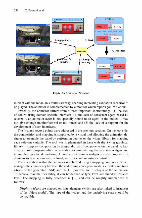
Fig. 6. An Animation Scenario
interact with the model in a multi-user way, enabling interesting validation scenarios tobe played. The animator is complemented by a monitor which reports goal violations.
Presently, the animator suffers from a three important shortcomings: (1) the lackof control using domain specific interfaces, (2) the lack of consistent agent-based UI(currently an animator actor is not specially bound to an agent in the model, it maynot give enough monitor/control or too much) and (3) the lack of a support for thedevelopment of such interfaces.
The first and second points were addressed in the previous sections. On the tool side,the composition and mapping is supported by a visual tool allowing the animation de-signer to assemble the panel by performing queries on the widget library for mappingeach relevant variable. The tool was implemented in Java with the Swing graphicallibrary. It supports composition by drag-and-drop of components on the panel. A Jav-aBeans based property editor is available for instantiating the available widgets andtuning their graphical rendering. A number of common widgets are also proposed fordomains such as automotive, railroad, aerospace and industrial control.
The integration within the animator is achieved using a mapping component whichmanages the consistency between the underlying conceptual model (ie. states and tran-sitions of the generated FSM) and the UI (controls and displays) of the animation.To achieve maximal flexibility, it can be defined at type level and tuned at instancelevel. The mapping is fully described in [19] and can be roughly summarized asfollows:
– Display widgets are mapped on state elements (which are also linked to instancesof the object model). The type of the widget and the underlying state should becompatible.

Goal-Oriented Design of Domain Control Panels 257
– Control widgets are mapped on an operation which is applied when a user action isperformed. The performer is the human agent associated with the enclosing panel.Operation arguments are derived from the input capabilities of the widget (eg.,rate of acceleration) and from other observable states (eg., current speed used asset point for a cruise control). Additional constraints can also be expressed usinginstance information (eg., speed applies to train controlled by the agent).
Figure 6 shows a typical animation scenario in two steps, respectively at top and bot-tom of the figure. The control panel, the lateral view of the train and the FSM instancesare displayed from left to right. The user playing the ”driver” role makes a request tostart the train (1). It is forwarded to the simulator (2,3) which accepts it (the guardbeing enabled because doors are closed). After the resulting transition (4), the train isnow moving and a state refresh is triggered on the control panel (speedometer) and thelateral view (“forward” arrow) (5,6).
In the above scenario, note that if the doors were opened when requesting the start,that user action would have been rejected. This could also be signalled at the UI level us-ing information widgets. This is an interesting feature for modelling automated backupmechanisms behind a human agent.
6 Related Work
FAUST and its animator, as outlined in this paper, mainly differs from existingMB-IDE approaches in the sense that four models are borrowed from requirementsengineering. Therefore, these models address functional (FR) and non-functional re-quirements (NFR) in the different models as opposed to solely some NFR in task-basedapproaches. For instance, it is possible in FAUST to automatically execute the under-lying models to obtain a genuine dialog whereas in traditional MB-IDEs, this dialogmodel should be generated from the task model, which represents a complex task. Fur-thermore, FAUST is based on all types of requirements, whereas traditional MB-IDEsmainly focus on user’s viewpoint and requirements, such as portability, usability, etc.They decompose the task into sub-tasks, but without considering seriously FR suchas domain constraints, robustness, reliability, performance, avoiding of conflict. Suchproperties are automatically obtained by construction and by generation in the FAUSTprocess, whereas they usually need to be done by hand in MB-IDEs, based on the ex-isting models [21].
Most animations exploit the task model [1] [13], whereas FAUST exploits all fourmodels. Other animation approaches combine system modelling and domain-basedvisualization:
– State-machines based approaches, such as in Statecharts or UML state diagrams.Tools like Statemate and Rhapsody allow those FSM to be executed and coupledwith graphical views. Recent work in the area explores reactive animations [5] inorder to combine and merge efforts in reactive design (using statecharts) and ani-mation techniques (such as Flash). Our approach has a similar purpose but focusesmore on earlier steps: our FSM are less structured but are consistent with goals.Both approaches and tools look essentially complementary and definitively worthcombining.
258 C. Ponsard et al.
– Tabular-based approaches, such as SCR and RSML and supported with tools likeSCR-toolset [7] and SpecTRM [9]. They focus on the system and model the input-output relation with a number of tables. The SCR animator has a visual composerwith a library of display and control widgets which can be mapped on table vari-ables. However the SCR library lacks a conceptual structure.
– Labeled transition system (LTS). LTSA, an LTS animator relies on scenebeans, adescriptive XML-based animation framework [11]. It provides low level animationprimitives (similar to SVG or Flash) which are easy to deploy and reuse even withother underlying modelling languages.
– In existing MB-IDEs approaches, the model that is usually chosen for representingthe dialog, such as a state-transition diagram, a statechart or a Petri net, shouldbe added and constructed by exploiting merely the task model, which leaves theproblem typically underspecified. It is therefore the responsibility of the designerto manually choose the right design options and to tweak the dialog model to obtaina version that is detailed enough to work.
The above approaches are based on operational specifications and lack the ability tocapture the goals, model the environment or reason about agents. Another goal-orientedapproach is Formal Tropos which also has an animator but without visualizationcapabilities [6].
Finally note the focus in this work is on the the design of display/control panels forcontrol systems—other approaches attempt to be more generic.
7 Conclusion and Future Work
In this paper, we exposed how goal models, borrowed from requirements engineering,can help in the design of control panels by providing a property driven paradigm asalternative to traditional data-oriented or task-oriented paradigms. A method to designconsistent control panel user interfaces from goal models was proposed as well as agoal-oriented widget library to assemble them. The result has then been deployed on arequirements animator as a tool for designing agent-oriented animations. The work hasbeen tested on a number of case studies such as a baggage lockers and a safety injectionsystem. It is now being validated on a larger industrial case: a floor door system for anautomated train.
FAUST and its animator mainly differ from existing MB-IDEs in that they exploitmodels borrowed from Requirements Engineering to produce a fully executable UI.In this way, we can also say that the underlying models are executable and dynamic,but they are also more expressive to the point that the dialog and a complete anima-tion can be automatically generated. In addition, it is possible in existing MB-IDEs toapply model-checking techniques to verify properties of interest, such as IFIP Dialogprinciples, but they need to be run by a human operator. In contrast, here, there is nodirect need to rely of these techniques because the resulting interface satisfies the FRand NFR by construction. It is impossible to produce a UI that is not compliant withthe constraints imposed by the various models. In the case the requirements were some-how flawed/incorrect in the first place, the goal-directed methodology provides meansto detect that because a conflict or inconsistency is likely to become apparent as the
Goal-Oriented Design of Domain Control Panels 259
refinement/agent assignment/operationalization process would fail at some point. Fi-nally, the most interesting difference is that the first model, i.e. the goal model, containsboth FR and NFR intertwined, as opposed to user goals only in traditional task-basedmodels.
In the end, both approaches should not be presented as alternatives but rather ascomplementary: the focus is here more upstream in the design process and based onproperty refinement rather than task refinement. The resulting operation model can beseen as a task model which can be handled by standard HCI techniques. The benefit ofusing the presented RE-based approach is the access to interesting reasoning techniquesabout the system, its environment and the interactions across their borderlines whichimpact the UI. This calls for a more in-depth comparison of HCI and RE approachesand the ways they can cross-fertilize.
At short term, we envision to address a number of limitations. Currently, our workfocuses mainly on control systems with agents responsible for a small part of the sys-tem. We would like to support supervising agents which have global monitoring/controlcapabilities on the system (eg., train dispatcher). Better structuring mechanisms are alsoneeded for mapping more elaborated data type and helping in the reuse of preassembledsub-panels. We also plan to provide an integration of the goal monitor to reports alarmsat interface level.
Acknowledgement
This work is financially supported by the European Union (ERDF and ESF) and theWalloon Region (DGTRE).
References
1. M. Biere, Birgit Bomsdorf, and Gerd Szwillus. The visual task model builder. In Chapter20, in Proceedings of CADUI’99.
2. G. Calvary, J. Coutaz, D. Thevenin, Q. Limbourg, L. Bouillon, and J. Vanderdonckt. Aunifying reference framework for multi-target user interfaces. Interacting with Computers,15(3), June 2003.
3. A. Dardenne, A. van Lamsweerde, and Stephen Fickas. Goal-directed requirements acquisi-tion. Science of Computer Programming, 20(1-2):3–50, 1993.
4. R. Darimont and A. van Lamsweerde. Formal refinement patterns for goal-driven require-ments elaboration. In 4th FSE ACM Symposium, San Francisco, 1996.
5. S. Efroni, D. Harel, and I. Cohen. Reactive animation. In Proc. 1st Int. Symposium on FormalMethods for Components and Objects (LNCS 2852), 2002.
6. A. Fuxman, L. Liu, M. Pistore, M. Roveri, and P. Traverso. Specifying and analysing earlyrequirements in tropos. Requirements Engineering Journal, 2004.
7. C. Heitmeyer, J. Kirby, and B. Labaw. Tools for formal specification, verification, and vali-dation of requirements. In Proc. COMPASS ’97, Gaithersburg, 1997.
8. R. Koymans. Specifying message passing and time-critical systems with temporal logic,LNCS 651. Springer-Verlag, 1992.
9. G. Lee, J. Howard, and P. Anderson. Safety-critical requirements specification and analysisusing spectrm. In Proc. 2nd Meeting of the US Soft. Syst. Safety WG, 2002.
260 C. Ponsard et al.
10. E. Letier and A. van Lamsweerde. Agent-based tactics for goal-oriented requirements elab-oration, 2002.
11. J. Magee, N. Pryce, D. Giannakopoulou, and J. Kramer. Graphical animation of behaviormodels. In Proc. ICSE’2000, Limerick, 2000.
12. Z. Manna and A. Pnueli. The Reactive Behavior of Reactive and Concurrent System.Springer-Verlag, 1992.
13. G. Mori, F. Paterno, and C. Santoro. Design and development of multi-device user interfacesthrough multiple logical descriptions. IEEE TSE, 30(8), August 2004.
14. F. Paterno. Model-based design and evaluation of interactive applications. In Springer Ver-lag, November 1999.
15. The Objectiver RE platform. http://www.objectiver.com.16. C. Ponsard, P. Massonet, A. Rifaut, J.F. Molderez, A. van Lamsweerde, and H. Tran Van.
Early verification and validation of mission critical systems. In 8th FMICS Workshop, Linz,2004.
17. A.R. Puerta. A model-based interface development environment. IEEE Software, 14(4),July/August 1997.
18. The FAUST toolbox. http://faust.cetic.be, 2004.19. H. Tran Van, A. van Lamsweerde, P. Massonet, and C. Ponsard. Goal-oriented requirements
animation. In 12th IEEE Int.Req.Eng.Conf., Kyoto, September 2004.20. A. van Lamsweerde and E. Letier. Handling obstacles in goal-oriented requirements engi-
neering. IEEE Transactions on Software Engineering, Special Issue on Exception Handling,26(10), October 2000.
21. J. Vanderdonckt. Advice-giving systems for selecting interaction objects. In Proc. of 1st Int.Workshop on UI to Data Intensive Systems, Edimburgh, 1999.
Related Documents