SPECIFICATIONS GO Shelter Designs Metrolinx July 26, 2016 gh3 architecture Project No.: xxx

Welcome message from author
This document is posted to help you gain knowledge. Please leave a comment to let me know what you think about it! Share it to your friends and learn new things together.
Transcript

SPECIFICATIONS
GO Shelter Designs Metrolinx
July 26, 2016
gh3 architecture Project No.: xxx
gh3 architecture Section 00 01 10 GO Shelter Designs TABLE OF CONTENTS Page 1
DIVISION 00 - PROCUREMENT AND CONTRACTING REQUIREMENTS
Document Title Discipline Pages 00 01 10 Table of Contents A 2
DIVISION 03 - CONCRETE Section Title Discipline Pages 03 20 00 Concrete Reinforcing S 4 03 30 00 Cast-In-Place Concrete S 8 03 35 23 Sandblasted Concrete Finish A 3
DIVISION 05 - METALS Section Title Discipline Pages 05 14 00 Structural Aluminum S 4 05 31 00 Steel Decking S 5 05 50 00 Miscellaneous and Metal Fabrications A 6
DIVISION 07 - THERMAL AND MOISTURE PROTECTION Section Title Discipline Pages 07 19 00 Water Repellents Sealer A 3 07 42 40 Composite Panels (Alternative) A 8 07 42 41 Aluminum Panels A 8 07 53 24 Adhered EPDM Membrane Roofing (Alternative) A 9 07 54 20 Adhered PVC Membrane Roofing A 8
DIVISION 08 - OPENINGS Section Title Discipline Pages 08 56 88 Single Glazed Systems A 6 - Finishing Door Hardware Schedule A 3 08 71 13 Automatic Door Equipment A 3 08 80 00 Glazing A 7
Section 00 01 10 gh3 architecture TABLE OF CONTENTS GO Shelter Designs Page 2
DIVISION 23 - HEATING, VENTILATING AND AIR-CONDITIONING (HVAC) Section Title Discipline Pages 23 83 00 Radiant Heating Systems E 2
DIVISION 26 - ELECTRICAL Section Title Discipline Pages 26 05 00 Common Work Results - Electrical E 12 26 05 20 Wire and Box Connectors (0-1, 000V) E 3 26 05 21.02 Wires and Cables (0-600V) E 3 26 05 22 Connectors and Terminations E 3 26 05 28 Grounding - Secondary E 4 26 05 29 Hangers and Supports for Electrical Systems E 3 26 05 31 Splitters, Junction, Pull Boxes and Cabinets E 3 26 05 32 Outlet Boxes, Conduit Boxes and Fittings E 3 26 05 34 Conduits, Conduit Fastenings and Conduit Fittings E 4 26 09 24 Lighting Control Devices - Low Voltage E 4 26 27 16 Electrical Cabinets and Enclosures E 3 26 27 26 Wiring Devices E 5 26 28 13.01 Fuses - Low Voltage E 2 26 29 03 Control Devices E 3 26 50 00 Lighting E 3
DIVISION 27 - COMMUNICATIONS Section Title Discipline Pages 27 10 05 Structured Cabling for Communications Systems E 4 27 51 16 Public Address and Mass Notification Systems E 3 27 51 23 Intercommunication and Program Systems E 3
DIVISION 28 - ELECTRONIC SAFETY AND SECURITY Section Title Discipline Pages 28 23 00 Video Surveillance E 5 END OF DOCUMENT
WSP Section 03 20 00 GO Shelter Designs CONCRETE REINFORCING Page 1
PART 1 - GENERAL
1.1 Related Requirements
.1 Section 03 30 00: Cast-in-Place Concrete.
1.2 References
.1 All referenced standards shall be the current edition or the edition referenced by the applicable Building Code in force at the time of building permit application, as noted on Structural Drawings.
.2 Canadian Standards Association (CSA International):
.1 CSA A23.1/A23.2, Concrete Materials and Methods of Concrete Construction/Test Methods and Standard Practices for Concrete.
.2 CSA A23.3, Design of Concrete Structures.
.3 CSA G30.18, Carbon Steel Bars for Concrete Reinforcement.
.4 CSA G40.20/G40.21, General Requirements for Rolled or Welded Structural Quality Steel/Structural Quality Steel.
.5 CSA W186, Welding of Reinforcing Bars in Reinforced Concrete Construction.
.3 Reinforcing Steel Institute of Canada (RSIC):
.1 Reinforcing Steel Manual of Standard Practice.
.4 American Concrete Institute (ACI):
.1 SP-66, ACI Detailing Manual.
1.3 Quality Assurance
.1 In accordance with Section 01 43 00 – Quality Assurance.
.2 Qualifications
.1 Welding of reinforcing steel to be performed by welders certified under CSA W186.
1.4 Quality Control
.1 Source Quality Control Submittals:
.1 Upon request, provide Consultant with certified copy of mill test report of reinforcing steel, showing physical and chemical analysis.
.2 Upon request, inform Consultant of proposed source of reinforcement material to be supplied.
1.5 Action and Informational Submittals
.1 Provide submittals in accordance with Section 01 33 00 - Submittal Procedures.
WSP Section 03 20 00 GO Shelter Designs CONCRETE REINFORCING Page 2
.2 Product Data:
.1 Submit manufacturer’s data sheets for mechanical rebar splices.
.3 Shop Drawings:
.1 Prepare shop drawings in accordance with RSIC Manual of Standard Practice unless the Contract Documents contain a more stringent requirement. Conform to ACI SP-66 Detailing Manual whenever a detail condition is not covered by any of the above.
.2 Submit plans, elevations, sections and details necessary to fabricate, place and review reinforcement without reference to structural drawings, including masonry wall reinforcement. Draw to scale not smaller than 1:50 (¼" = 1'-0").
.3 Show on drawings:
.1 Sizes, spacings and locations of reinforcement, with identifying labels.
.2 Bar bending details.
.3 Lengths of all lap splices.
.4 Types and locations of mechanical splices.
.5 Bar lists.
.6 Quantities of reinforcement (including all rebars added to accommodate installation).
.7 Construction joint, control joint and pour gap locations.
.8 Strip dimensions for flat slab and flat plate.
.9 Concrete cover.
.4 Do not release for fabrication reinforcing bars whose length may be affected by field conditions, such as the final elevation of footings, until obtaining the required field measurements.
.5 For resubmission shop drawings, revisions shall be bubbled.
.6 Submit a final set of drawings incorporating the revisions and site conditions.
PART 2 - PRODUCTS
2.1 Materials
.1 Reinforcing steel: carbon steel, deformed bars to CSA G30.18., unless indicated otherwise.
.2 Weldable Reinforcing steel: weldable low alloy steel deformed bars to CSA G30.18.
.3 Chairs, bolsters, bar supports, spacers: to CSA A23.1/A23.2.
.4 Mechanical splices: to develop 125% of specified rebar yield strength.
WSP Section 03 20 00 GO Shelter Designs CONCRETE REINFORCING Page 3 PART 3 - EXECUTION
3.1 Fabrication
.1 Fabricate reinforcing steel in accordance with CSA A23.1/A23.2 and Reinforcing Steel Manual of Standard Practice.
.2 Stagger mechanical splices 750mm (2’-6”) unless otherwise noted on drawings.
.3 Weld reinforcement in accordance with CSA W186 where indicated.
.4 Ship bundles of bar reinforcement, clearly identified in accordance with bar lists.
.5 Provide standard hooks at ends of all hooked bars.
.6 Substitute different size bars only if permitted in writing by the Consultant
3.2 Field Bending
.1 Do not field bend or field weld reinforcement except where indicated or authorized by Consultant.
.2 When field bending is authorized, bend without heat, applying slow and steady pressure.
.3 Replace bars which develop cracks or splits.
3.3 Placing Reinforcement
.1 Place reinforcing steel as indicated on reviewed placing drawings and in accordance with CSA A23.1/A23.2.
.2 Remove all loose scale, dirt, oil or other coatings which would reduce bond.
.3 Ensure cover to reinforcement is maintained during concrete pour.
.4 Use bar supports for beams and slabs.
.5 Use precast concrete chairs where supports rest on the ground. Where welded wire fabric is used in slabs-on- grade, place precast concrete chairs at 600 mm (2’-0”) on centre each way.
.6 Do not splice reinforcing at locations other than shown on placing drawings without Consultant’s written approval.
.7 Do not cut reinforcement without Consultant’s written approval.
.8 Exposed concrete surfaces:
.1 Use plastic or plastic tipped bar supports and spacer with colour to match concrete.
.9 Do not field weld reinforcement except where indicated or authorized by the Consultant.
3.4 Field Quality Control

WSP Section 03 20 00 GO Shelter Designs CONCRETE REINFORCING Page 4
.1 Bring to the attention of the Consultant any defects or deficiencies in the work together with a proposal for remedy. The Consultant will decide what corrective action may be taken, and will issue the necessary instructions.
.2 Construction Review:
.1 General review during construction by the Consultant will be carried out by examination of representative samples of the work.
.2 Do not close forms or pour concrete before reinforcing steel is reviewed.
.3 Construction review reports will outline any deficiencies found.
.3 Inspection and Testing:
.1 An independent Inspection and Testing Agency will be appointed to carry out inspection and testing of concrete reinforcing.
.2 When requested, the Agency will review mill test reports and correlate reinforcing steel supplied with mill test reports provided.
.3 If reinforcing steel cannot be correlated to mill test reports, the Agency will conduct a sufficient number of tests to determine the yield strength of the reinforcing steel supplied.
END OF SECTION 03 20 00
WSP Section 03 30 00 GO Shelter Designs CAST-IN-PLACE CONCRETE Page 1
PART 1 - GENERAL
1.1 Related Requirements
.1 Section 03 20 00: Concrete Reinforcing.
.2 Section 03 35 00: Concrete Finishing.
1.2 References
.1 All referenced standards shall be the current edition or the edition referenced by the applicable Building Code in force at the time of building permit application, as noted on Structural Drawings.
.2 Canadian Standards Association (CSA International):
.1 CSA A23.1/A23.2, Concrete Materials and Methods of Concrete Construction/Methods of Test and Standard Practices for Concrete.
.2 CSA A283, Qualification Code for Concrete Testing Laboratories.
.3 CSA A3000, Cementitious Materials Compendium (Consists of A3001, A3002, A3003, A3004 and A3005).
1.3 Quality Assurance
.1 Qualifications
.1 Concrete supplier to have a valid “Certificate of Ready Mixed Concrete Production Facilities” issued by the relevant Ready Mixed Concrete Association.
1.4 Quality Control
.1 Minimum two weeks prior to starting concrete work, provide valid certificate from plant delivering concrete.
.1 Provide test data and certification by qualified independent inspection and testing laboratory that materials and mix designs used in concrete mixture will meet specified requirements.
.2 Minimum four weeks prior to starting concrete work, provide proposed quality control procedures on following items:
.1 Hot weather concrete.
.2 Cold weather concrete.
.3 Curing.
.4 Finishing.
.5 Protection.
1.5 Administrative Requirements
WSP Section 03 30 00 GO Shelter Designs CAST-IN-PLACE CONCRETE Page 2
.1 Pre-installation Meeting: convene pre-installation meeting one week prior to beginning concrete works. Ensure key personnel to attend.
.2 Batch Logs: keep record of each batch delivered to site.
.3 Concrete Delivery Slips: Keep all concrete delivery slips (“driver’s tickets”) on site until building is completed. Record on delivery slip where concrete was placed, including time and date.
.4 Record Drawings: Record on a set of Structural Drawings extent of each pour including pour date and falsework removal date. Also record all field changes, including footing elevations.
1.6 Action and Informational Submittals
.1 Minimum 2 weeks prior to starting concrete work, submit all concrete mix designs, and indicate where each concrete mix is to be used.
.2 Minimum submission requirements for each concrete mix design shall include the following:
.1 Minimum specified compressive strength at 28 day.
.2 Maximum aggregate size.
.3 Aggregate type (if not normal density).
.4 Concrete density range, wet and dry (if not normal density).
.5 CSA exposure class.
.6 Cement type (if not type GU).
.7 Percentage and type of supplemental cementing materials.
.8 Maximum water/cemetitious ratio.
.9 Assumed method of placement of concrete.
.10 Corrosion inhibitor (name and quantity, if applicable).
.11 Plastic or steel fibres (type, name and quantity, if applicable).
.12 Alkali-aggregate resistance.
.13 Maximum time from batching to placing concrete (if retarding admixtures are used).
.3 Concrete pours: provide accurate records of poured concrete items indicating date and location of pour, concrete mix used, ambient air temperature and test samples taken.
.4 On completion of the works, provide written report to Consultant certifying that the concrete in place meets performance requirements established in PART 2 - PRODUCTS.
PART 2 - PRODUCTS
WSP Section 03 30 00 GO Shelter Designs CAST-IN-PLACE CONCRETE Page 3 2.1 Design Criteria
.1 To CSA A23.1/A23.2, Alternative 1 – Performance, and as described under Mixes and on Structural Drawings.
2.2 Performance Criteria
.1 Concrete supplier to meet the concrete performance criteria established by the Consultant and to provide verification of compliance.
2.3 Materials
.1 Portland Cement: to CSA A3001.
.2 Cementitious hydraulic slag: to CSA A3000.
.3 Fly ash: to CSA A3001, Type CI.
.4 Water: to CSA A23.1.
.5 Aggregates: to CSA A23.1/A23.2.Do not use recycled concrete as aggregate.
.6 Admixtures: not to contain chlorides.
.7 Corrosion-inhibiting admixture: calcium nitrate solution.
.8 Shrinkage compensating grout: premixed compound consisting of non-metallic aggregate, Portland cement, water reducing and plasticizing agents to CSA A23.1/A23.2. Minimum compressive strength: 40 MPa at 28 days.
.9 Non premixed dry pack grout: composition of non metallic aggregate and Portland cement with sufficient water for mixture to retain its shape when made into ball by hand and capable of developing compressive strength of 40 MPa at 28 days.
.10 Evaporation reducer: water based polymer liquid forming continuous monomolecular temporary film on fresh concrete surface.
.11 Penetrating sealer: single component, water based clear water repellent with 40% active ingredient Alkylalkoxysilane.
.12 Bonding adhesive: Synthetic latex.
.13 Vapour barrier: 0.25mm polyethylene to CAN/CGSB-51.34.
.14 Control joint filler: semi-rigid filler to protect against slab edge breakdown:
.1 For sawcuts made with “Soff-Cut” saw: two component epoxy.
.2 For conventional sawcuts in interior slab: two component epoxy urethane.
.3 For conventional sawcuts in exterior slabs: two or multy component polyurethane based elastomeric.
.15 Crack Filler: low viscosity epoxy resin.
2.4 Mixes
WSP Section 03 30 00 GO Shelter Designs CAST-IN-PLACE CONCRETE Page 4
.1 Use ready-mix concrete. Proportion concrete in accordance with CSA A23.1, Alternative 1 - Performance Method for Specifying Concrete.
.2 Set performance characteristics of concrete in plastic state in coordination with all trades involved.
.3 Meet performance criteria of concrete in hardened state as shown on Structural Drawings and provide verification of compliance.
.4 Use water-reducing agent in all concrete.
.5 Do not use admixtures containing chlorides.
.6 Supplementary cementing materials (SCM):
.1 Confirm to CSA A23.1.
.2 Follow slag and fly ash manufacturers’ directions for proportioning and mixing of concrete.
.3 Do not use SCM in architecturally exposed concrete.
.4 Use a minimum of 15% SCM for concrete that is not architecturally exposed.
.5 Fly ash not to exceed more than 15% of total cementitious material
.6 Limit SCM content for floors with special finishes (such as Retroplate), to be compatible with the finish.
.7 Reduce W/C ratio to 0.45 where using high SCM concrete for slabs and other horizontal finished surfaces, in order to reduce bleed water and to increase rate or strength gain.
PART 3 - EXECUTION
3.1 Preparation
.1 Provide minimum 24 hours’ notice prior to placing of concrete.
.2 Obtain written approval of each foundation bearing surface by the Geotechnical Consultant before placing concrete.
.3 Remove water and disturbed soil from excavations before placing concrete.
.4 Before placing slab-on-grade, confirm that subgrade and backfill meet specifications and are free of frost and surface water.
.5 Provide vapour barrier under slabs placed on the ground including slabs-on-grade and framed slabs as described by the Architectural specifications.
.6 Place concrete reinforcing in accordance with Section 03 20 00 - Concrete Reinforcing.
3.2 Installation/Application
WSP Section 03 30 00 GO Shelter Designs CAST-IN-PLACE CONCRETE Page 5
.1 Set sleeves, conduits, pipe hangers, weep hole tubes, drains and other inserts and openings as indicated or specified elsewhere.
.2 Refer to Notes on Structural Drawings for maximum size and minimum spacing of conduits.
.3 Check locations and sizes of sleeves and openings shown on Structural Drawings with Architectural, Mechanical and Electrical Drawings. Notify Consultant of any discrepancies.
.4 Obtain Consultant’s approval for any required sleeves and openings which are not shown on Structural Drawings.
.5 Set special inserts for strength testing as required for non destructive method of testing concrete
.6 Set anchor rods using templates under supervision of appropriate trade prior to placing concrete. Locate each anchor rod group to within 6mm (1/4”) of required location.
3.3 Placing Concrete
.1 Place concrete in accordance with CSA A23.1.
.2 Delivery and place concrete with minimum re-handling.
.3 If concrete is pumped or placed pneumatically, control discharge velocity to prevent separation or scattering of concrete mix ingredients.
.4 Do not overload forms.
.5 Cast slabs with a top surface that is level or sloping as required by the Drawings. Allow for cambering where required. Set top of slab below finished floor level by the distance required for the type of applied finish.
.6 Concrete exposed to view:
.1 Exposed surfaces to be dense, even, uniform in colour, texture and distribution of exposed aggregate.
.2 Defects such as honeycombing, voids, loss of fines, visible flow lines, cold joints or excessive bug holes may be cause for rejection at the discretion of the Consultant.
.7 Maintain accurate records of poured concrete items to indicate date, location of pour, quality, air temperature and test samples taken.
3.4 Finishing Concrete
.1 Finish concrete to CSA A23.1/A23.2.
.2 Cooperate with any trade applying finishes to concrete surfaces and provide surfaces which will ensure adequate bond. Provide chases and reglets where required.
.3 Finishing Flatwork:
WSP Section 03 30 00 GO Shelter Designs CAST-IN-PLACE CONCRETE Page 6
.1 See Section 03 35 00 - Concrete Floor Finishing.
.2 Protect concrete during finishing process. Use evaporation reducer during severe drying conditions.
.3 Surface Tolerances:
.1 Concrete surface tolerance to CSA A23.1, Straightedge Method.
.2 Unless otherwise noted, conform to finish tolerance Class A, Table 22 of A23.1-09.
3.5 Concrete Curing and Protection
.1 At a minimum cure and protect concrete in accordance with CSA A23.1
.2 For concrete containing supplementary cementing materials, curing and protection times may need to be extended beyond those outlined by CSA A23.1 to achieve the required structural properties.
.3 Cure slab surfaces immediately after finishing is completed. Unless otherwise noted, use a curing compound compatible with applied finishes.
.4 Concrete exposed to view:
.1 Protect during construction period from wear, damage, marking, discolouration, staining and becoming coated with concrete leakage.
.2 Unless rejected, repair damage and remove marks and stains to the approval of the Consultant.
3.6 Slabs on Grade
.1 Construction joints and sawcut joints:
.1 Refer to drawing notes for maximum spacing requirements.
.2 Saw cut depth to be equal to one quarter of the concrete thickness.
.3 Locate joints on column lines wherever possible and on intermediate lines, which result in approximately square panels, without re-entrant corners.
.4 Do not create “L” shaped panels nor “T” shaped joint intersections.
.5 Protect edges of sawcuts from breakage.
.6 Clean out sawcuts in exposed concrete and fill with control joint filler after concrete is at least 120 days old.
.7 Sawcut top 25 mm (1") at construction joints in exposed concrete for a width of 5 mm (3/16") and fill with control joint filler after concrete is at least 120 days old.
.8 Clean out sawcuts in other concrete and fill with a sand-cement paste one month prior to installing floor coverings.
.2 Cracks in Slabs-on-Grade:
WSP Section 03 30 00 GO Shelter Designs CAST-IN-PLACE CONCRETE Page 7
.1 Extensive cracking of slabs-on-grade or cracks in excess of 3mm (1/8”) in width may be cause for rejection of slab or portion of slab at Consultant’s discretion.
.2 Protect edges of cracks in slabs-on-grade from breakage.
.3 Exposed slab on grade: Unless slab is rejected, repair cracks that are over 0.4 mm (0.016") wide:
.1 Fill cracks with a sand-cement grout after concrete is at least 120 days old.
.2 Seven days later, cut out top 20 mm (3/4") of crack for a width of 5 mm (3/16") and fill with control joint filler.
3.7 Penetrating sealer
.1 Concrete to receive penetrating sealer to be at least 28 days old.
.2 Surfaces to be treated with the sealer to be dry and free of dirt and other contaminants.
.3 Completely remove all curing compounds before the sealer application.
.4 Follow manufacturer’s recommendations for coverage rate and application procedure.
.5 Do not apply in inclement weather or if ambient air temperature or concrete surface temperature is less than 5 C or more than 38C.
3.8 Grouting Under Base Plates and Bearing Plates
.1 Grout under base plates and bearing plates using procedures in accordance with manufacturer's recommendations.
.2 Provide 100% contact over grouted area.
.3 Grout column base plates as soon as steelwork is completed.
.4 Do not add load on steelwork until grouting is completed and grout strength has reached at least 20 MPa.
3.9 Field Quality Control
.1 Bring to the attention of the Consultant any defects or deficiencies in the work together with a proposal for remedy. The Consultant will decide what corrective action may be taken, and will issue the necessary instructions.
.2 Construction Review:
.1 General review during construction by the Consultant will be carried out by examination of representative samples of the work.
.2 Construction review reports will outline any deficiencies found.
.3 Inspection and Testing:

WSP Section 03 30 00 GO Shelter Designs CAST-IN-PLACE CONCRETE Page 8
.1 An independent Inspection and Testing Agency (certified under CSA A283 with category to suit testing provided) will be appointed to carry out inspection and testing of concrete and concrete materials and check conformance with applicable Standards and Contract documents.
.2 The Agency will submit reports to the Consultant, Structural Engineer, Contractor / Construction Manager, Concrete Supplier and Municipal Authorities. Reports will include the Supplier’s mix design numbers, locations in structure to which the tests relate and comments on abnormal results and conditions. The reports will be provided not later than five working days after the testing is completed.
.3 Sampling, storing, curing and testing of concrete will be in accordance with CSA A23.1/A23.2.
.4 The Agency will review all submittals pertaining to concrete mix designs and certification of plant, equipment and materials.
.5 Compressive Strength Testing:
.1 One test is required for each 100 cubic meters of placed concrete, but not less than one test for each concrete mix placed each day.
.2 A group of three cylinders for each test will be provided, One specimens will be tested at 7 and one at 28 days. The third specimen will be tested at 56 days if the required strength at 28 days is not achieved.
.3 If the final concrete strength is specified at 56, 90 or 120 days, a group of four cylinders will be provided. One specimen will be tested at 7 and one at 28 days, with the third specimen tested at the time the final concrete strength is specified. If the required strength is not achieved at the time specified, the fourth specimen will be tested 28 days later.
.4 One additional cylinder will be provided for each concrete mix during cold weather concreting. The specimens will be cured on site adjacent to and under the same conditions as the work they represent, and will be tested after 7 days.
.5 If standard on site cured cylinders are used to determine concrete strength prior to removal of formwork, they will be kept adjacent to and under the same conditions as the work they represent.
.6 If pull out tests are used to determine concrete strength prior to removal of formwork, the Inspection and Testing Agency will supply, locate and test pull out inserts. The inserts not to be located on surfaces exposed to view.
.6 Air Entrainment Testing:
.1 One standard test for air content in plastic concrete will be conducted for each 100 cubic meters of each air entrained concrete mix.
.2 One standard test per ASTM C457 will be conducted to determine air void spacing factor in hardened concrete for each 100 cubic meters each air entrained concrete mix.

WSP Section 03 30 00 GO Shelter Designs CAST-IN-PLACE CONCRETE Page 9
.7 Permeability Testing:
.1 One chloride ion permeability test will be conducted for each 100 cubic meters of all class C1 concrete mixes used for floor.
.8 Inspection and testing by the Agency will not augment or replace the Contractor’s quality control nor relieve him of his contractual responsibility.
.9 Assist the Agency in its work. Notify the Agency as to the concreting schedule and before each pour. Provide concrete samples.
END OF SECTION 03 30 00
gh3 architecture Section 03 35 23 GO Shelter Designs SANDBLASTED CONCRETE FINISH Page 1
1 General 1.1 SECTION INCLUDES
.1 Labour, Products, equipment and services necessary for sandblasted concrete finish Work performed on Site in accordance with the Contract Documents.
1.2 REFERENCES
.1 ASTM D4285, Method for Indicating Oil or Water in Compressed Air. 1.3 SUBMITTALS
.1 Product data: Submit duplicate copies of manufacturer's Product data for aggregate types proposed for use in accordance with the Conditions of the Contract.
.2 Shop drawings: Submit shop drawings in accordance with the Conditions of the
Contract indicating the proposed methods of protecting adjacent building elements. 1.4 QUALITY ASSURANCE
.1 Perform Work of this Section by a company that has adequate equipment, skilled tradesmen, and a minimum of five years proven experience in sandblasted concrete finish work on projects of a similar size and nature. Submit to Consultant substantiating information as proof of compliance.
1.5 SITE CONDITIONS
.1 Do not commence sandblasting until concrete has properly and uniformly cured a minimum of 28 days.
2 Products 2.1 MATERIALS
.1 Abrasive: Hard, angular sand and blasting grit abrasive that will not adversely affect the colour of the finished surface. Grit gradation shall be selected by the Contractor to achieve the desired finish.
Section 03 35 23 gh3 architecture SANDBLASTED CONCRETE FINISH GO Shelter Designs Page 2
2.2 EQUIPMENT
.1 Provide safe and adequate equipment on the site to execute the work, hoisting, scaffolding, staging, enclosures to prevent spread of dust, safety protection equipment, tools, plant and other equipment required for the execution and completion of the work.
.2 Air compressors shall be rotary type and have ample capacity capable of providing, at
each nozzle, not less than 640 KPa within 3000 mm of the nozzle.
.3 Air shall be free when tested in conformance with ASTM D4285.
.4 Gun nozzle shall be of the Venturi type, either tungsten carbide or norbide and have a minimum inside diameter of 8 mm. Nozzle shall have automatic cut-off for proper control by operator.
.5 Hose lines shall be capable of dissipating static electricity and have adequate strength
for the specified pressure. inside diameter of hose shall not be less than 40 mm to maintain abrasive in proper suspension while travelling in the hose.
3 Execution 3.1 EXAMINATION
.1 Verify condition and dimensions of previously installed Work upon which this Section depends. Report defects to Consultant. Commencement of Work means acceptance of existing conditions.
3.2 PREPARATION
.1 Protect surrounding and adjoining work by adequately covering with tarpaulins or other suitable protective covering. Enclose each work area with suitable tarpaulins or other tarpaulins to confine the dust and grit within the work area and prevent spread to adjoining areas. Make good all damage caused by failure to provide suitable and adequate protection and be fully responsible for any damage of claims resulting from this operation.
.2 Supply and install temporary protection to adjacent surfaces to prevent damage
resulting from Work of this Section.
gh3 architecture Section 03 35 23 GO Shelter Designs SANDBLASTED CONCRETE FINISH Page 3
.3 Suitably mask and protect from damage all inserts and other materials placed in position before the work of this section is performed.
.4 Fill all bug holes larger than 20 mm diameter and rub down flush any fins at
formwork joints. 3.3 SANDBLASTED CONCRETE FINISH
.1 Do not proceed until sample panel/mock-up has been approved.
.2 Sandblasting will only be permitted when surfaces being sandblasted are dry.
.3 Execute the work using the required gun technique, proceeding progressively over the entire area being finished to product a uniform even texture throughout with the same degree of aggregate exposure as that of the approved sample.
.4 Class of aggregate exposure may be defined as follows: .1 Class 2 (Light): Exposes additional fine aggregate and possible edges of some
course aggregate.
.5 Under this classification system , there is no established requirement for the total amount of surface material to be removed. Each class is related to the size of the aggregate involved. However, if required, the following approximate depths of exposure for each class may be used: .1 Class 2: 1.6 mm
.6 The approximate depths of exposure are measured from the original surface to the
typical depth of matrix removed between pieces of coarse aggregate.
.7 The depth and texture required shall be Class 2 with the amount of material to be removed being approximately 1.6 mm.
3.4 CLEANING
.1 Remove and dispose of all debris resulting from the work of this Section as the work proceeds, leaving work areas broom clean at the end of each day.
END OF SECTION

WSP Section 05 14 00 GO Shelter Designs STRUCTURAL ALUMINUM Page 1
PART 1 - GENERAL
1.1 References
.1 All referenced standards to be the current edition or the edition referenced by the applicable Building Code in force at the time of building permit application, as noted on Structural Drawings.
.2 Canadian Standards Association (CSA International):
.1 All structural aluminum elements have been designed in accordance with CAN/CSA-S157S05/S157.1-05(R2015) – Strength Design in Aluminum.
1.2 Quality Assurance
.1 Perform welding of aluminum in accordance with requirements of CSA W59.2 and CSA S244. Fabricator to be certified to Division 2.
1.3 Action and Informational Submittals
.1 Shop Drawings:
.1 Provide shop drawings stamped and signed by the Professional Engineer responsible for aluminum connections.
.2 Before submitting shop drawings, provide a letter signed and sealed by that Engineer stating that he has been engaged to undertake the responsibility for the above. Also submit a copy of that Engineer’s Certificate of Authorization, and proof of his liability insurance.
.3 If additional information is required from the Consultant, allow a minimum of five working days for the Structural Engineer to review and respond to the request for information.
.4 Shop drawings shall show and specify connections utilized within the structural system as well as connections to and loads imposed upon the structural system indicated in these plans..
.2 Erection drawings:
.1 Submit erection drawings indicating details and information necessary for assembly and erection purposes including:
.1 Description of erection methods.
.2 Sequence of erection.
.3 Temporary bracings.
.4 Beam sizes (in addition to beam marks).
.3 Fabrication drawings:
WSP Section 05 14 00 GO Shelter Designs STRUCTURAL ALUMINUM Page 2
.1 Submit fabrication drawings showing designed assemblies, member sizes, components and connections. Show on drawings:
.1 Material specifications.
.2 Surface preparation.
.3 Section splices.
.4 Types of shop and field connections.
.5 Net weld lengths.
.6 Architectural clearance lines and finishes where connections could encroach other works.
.7 Beam and column web holes required for services and reinforcing around them.
.4 On completion of erection, submit a letter signed and sealed by the Professional Engineer responsible for structural aluminum connections certifying that the work has been completed in accordance with all contract documents.
.5 For resubmission shop drawings, revisions shall be bubbled.
.6 Submit a final set of drawings incorporating the revisions and site conditions.
PART 2 - PRODUCTS
2.1 Design Requirements
.1 When requested, submit sketches and design calculations stamped and signed by the Professional Engineer responsible for connection design.
.2 Connection design to include consideration of all pass-through forces, including tension, compression, moment or shear. Provide local reinforcement at connection or joint as required.
.3 Where axial forces occur in beams framing to opposite sides of a supporting member, design connections for a pass-through force equal to the smaller axial force. If beam sizes differ, assume the axial force is centred in the smaller beam. Where beams frame into columns, connect each beam for the axial force shown.
.4 Follow conceptual connection details if shown on structural drawings. Do not change without the Consultant’s written approval. If welds are defined on drawings, the sizes shown are minimum requirements which might need to be increased to suit connection design.
.5 Where moment connections are called for but values are not indicated, design for moment capacity of the smaller member in the connection.
.6 Where holes for services are required through webs of beams or columns, coordinate size and location with Architectural, Mechanical and Electrical drawings, and show on fabrication drawings.
2.2 Materials
WSP Section 05 14 00 GO Shelter Designs STRUCTURAL ALUMINUM Page 3
.1 Structural aluminum:
.1 Aluminum Alloy 6061-T6.
.2 Structural aluminum framing shall conform to CSA HA Series.
.3 Aluminum shall be the alloys and tempers as specified on the drawings.
.4 Structural aluminum extrusions as indicated on drawings, as distributed by Samuel, Son, & Co, Limited or approved alternative.
2.3 Fabrication
.1 All aluminum members shall be fabricated in accordance with the Aluminum Design Manual, current edition and with reviewed shop drawings.
PART 3 - EXECUTION
3.1 General
.1 Structural aluminum work: in accordance with CSA-S157S05.
.2 Welding: in accordance with CSA W59.2 and CSA S244.
3.2 Erection
.1 There shall be no welded connection unless allowed and shown on the drawings.
.2 Provide dissimilar metal separators at all junctions of aluminum framing and structural steel, concrete and masonry
3.3 Field Quality Control
.1 Bring to the attention of the Consultant any defects or deficiencies in the work together with a proposal for remedy. The Consultant will decide what corrective action may be taken, and will issue the necessary instructions.
.2 Construction Review:
.1 General review during construction by the Consultant will be carried out by examination of representative samples of the work.
.2 Construction review reports will outline any deficiencies found.
.3 Inspection and testing:
.1 An Inspection and Testing Agency will be appointed to carry inspection and testing of all structural aluminum.
.2 Do not commence fabrication until details of inspection have been worked out with the Agency.
.3 The Inspection Agency will submit reports to the Consultant, Structural Engineer, Contractor and Municipal Authorities covering the Work inspected and provide details of errors or deficiencies observed.
WSP Section 05 14 00 GO Shelter Designs STRUCTURAL ALUMINUM Page 4
.4 Work will be inspected in the shop and when erected. Store fabricated members in the shop so that they are accessible for inspection. Items to be cast into concrete will be inspected on site before being installed.
.5 Inspection will include:
.1 Checking that the mill test certificates or producer’s certificates are properly correlated to materials and products supplied for the project or that legible markings were made on the material and products by the producers in accordance with the applicable standards. Where this is not possible, notify the Consultant and if requested carry out sample tests as described below.
.2 Confirming that all materials meet specifications.
.3 Sampling fabrication and erection procedures for general conformity with the requirements of the Contract.
.4 Checking fabricated members against specified member shapes.
.5 Visual inspection of all welded connections including spot checking of joint preparation and fit up.
.6 Sample checking bolted joints.
.7 Sample checking that tolerances are not exceeded during erection including fit-up of field welded joints.
.8 Inspection of field cutting.
.9 Inspection of grouting under base plates and bearing plates.
.10 Checking levelness of leveling plates.
END OF SECTION 05 12 23

WSP Section 05 31 00 GO Shelter Designs STEEL DECKING Page 1
PART 1 - GENERAL
1.1 References
.1 All referenced standards shall be the current edition or the edition referenced by the applicable Building Code in force at the time of building permit application, as noted on Structural Drawings.
.2 Canadian Standards Association (CSA International):
.1 CSA S136, North American Specification for the Design of Cold Formed Steel Structural Members.
.2 CSA W47.1, Certification of Companies for Fusion Welding of Steel Structures.
.3 CSA W55, Certification of Companies for Resistance Welding of Steel and Aluminum.
.4 CSA W48, Filler Metals and Allied Materials for Metal Arc Welding.
.5 CSA W59, Welded Steel Construction, (Metal Arc Welding).
.3 ASTM International Inc.:
.1 ASTM A653/A653M, Standard Specification for Steel Sheet, Zinc-Coated (Galvanized) or Zinc-Iron Alloy-Coated (Galvannealed) by the Hot-Dip Process.
.2 ASTM A792/A792M, Standard Specification for Steel Sheet, 55% Aluminum-Zinc Alloy-Coated by the Hot-Dip Process.
.4 Canadian Sheet Steel Building Institute (CSSBI):
.1 CSSBI 10M, Standard for Steel Roof Deck.
1.2 Quality Assurance
.1 Qualifications
.1 Companies to be certified under Division 1 or 2.1 of CSA W47.1 for fusion welding of steel and/or CSA W55.3 for resistance welding.
.2 Welders to be CWB approved for deck welding by Canadian Welding Bureau.
.3 Engage a Professional Engineer licensed in the place where the project is located to be responsible for design and installation of all decking.
.4 The Professional Engineer designing steel decking to hold a Certificate of Authorization, and to carry min. $1,000,000.00 in liability insurance
1.3 Action and Informational Submittals
.1 Provide submittals in accordance with Section 01 33 00 - Submittal Procedures.
.2 Product Data:
WSP Section 05 31 00 GO Shelter Designs STEEL DECKING Page 2
.1 Submit manufacturer's data sheets for each deck type.
.2 When requested, provide data to substantiate deck load capacity, including diaphragm shear capacity.
.3 Shop Drawings:
.1 Provide drawings stamped and signed by a Professional Engineer responsible for design of steel decking.
.2 Submit a copy of that Engineer’s Certificate of Authorization, and proof of his liability insurance
.3 Show on drawings:
.1 Deck layout.
.2 Deck profile and base steel thickness.
.3 Type of deck metallic coating.
.4 Gravity and uplift loads, diaphragm shear and deflection requirements the deck is designed for.
.5 Type and spacing of connections to supports and between sheets.
.6 Projections and openings.
.7 Reinforcement details and accessories.
.4 For resubmission shop drawings, revisions shall be bubbled.
.5 Submit a final set of drawings incorporating the revisions and site conditions.
PART 2 - PRODUCTS
2.1 Design Requirements
.1 Design steel deck and connections to CSA S136, CSSBI 10M and CSSBI 12M. Design loads, section depths and minimum steel thicknesses are shown on Structural Drawings.
.2 If increased wind uplift loads applicable at roof edges and corners are not specifically noted on Structural Drawings, increase the minimum design wind uplift shown (which is applicable in the zones away from roof edges) in accordance with the Users’s Guide to NBC – Structural Commentaries (Part 4 of Division B.
.3 Design reinforcement for deck openings up to 450 (18”) wide across flutes.
.4 Deck profiles and welding to satisfy requirements of any Fire Rated Assembly Design specified for the Project.
.5 Deflection limitations for roof deck:
.1 1/360 of span under specified live load.
WSP Section 05 31 00 GO Shelter Designs STEEL DECKING Page 3
.2 1/240 of span under total load.
2.2 Materials
.1 Galvanized deck: Zinc (Z) coated steel sheet to ASTM A653/A653M, structural quality Grade 230, with Z275, coating or aluminum-zinc alloy (AZ) coated steel sheet to ASTM A792/A792M, structural quality grade 230 with AZ 150 coating.
.2 Fasteners for galvanized deck and prefinished deck: coated or stainless steel, hex head, self-tapping screws with EPDM bonded washers.
.3 Powder-actuated fasteners: Hilti Decking Fastening System.
.4 Cover plates, closures, edge forms and flashings: steel sheet with minimum base steel thickness of 0.76 mm. Metallic coating same as deck material.
2.3 Types of Decking
.1 Roof deck: with interlocking side laps. Centre to centre rib spacing to be:
.1 150 mm (6") for 38 mm (1.5") deep deck
2.4 Fabrication
.1 Conform to CSA S136 and CSA W59.
.2 Fabricate sections from steel sheets by rolling. Form integral ribs which will bear on supports and form interlocking male and female side laps.
PART 3 - EXECUTION
3.1 General
.1 Structural steel work: in accordance with CSA S136, CSSBI 10M and CSSBI 12M.
.2 Welding: in accordance with CSA W59, except where specified otherwise.
3.2 Examination
.1 Verification of Conditions: verify that conditions of substrates previously installed under other Sections or Contracts are acceptable for steel decking installation.
.1 Visually inspect substrate.
.2 Inform Consultant of unacceptable conditions immediately upon discovery.
.3 Proceed with installation only after unacceptable conditions have been remedied.
3.3 Erection
.1 Erect steel deck in accordance with CSA S136, CSSBI 10M, CSSBI 12M, and reviewed shop drawings.
.2 Do not overload structure during erection. Place deck bundles near columns.
WSP Section 05 31 00 GO Shelter Designs STEEL DECKING Page 4
.3 Align deck end to end for accurate fit with corresponding sections. Sections to be parallel, even and straight.
.4 Locate deck rib directly over perimeter angles spanning parallel to deck and at same elevation as underside of deck.
.5 Lap over supports. Minimum lap 50 mm (2"), max lap100 mm (4").
.6 Connections
.1 Use connections specified on reviewed shop drawings, to suite uplift, diaphragm shear, requirements of any Fire Rated Assembly Design.
.2 Connect deck to supporting angles using mechanical fasters or power actuated fasteners. Connect male and female side laps using mechanical fasteners or by interlocking with a button punch
.3 Use coated or stainless steel fasteners for all prefinished and galvanized deck, as well as for decks at steep slopes. Side laps for prefinished or galvanized deck to be mechanically interlocked.
.7 Immediately after deck is permanently secured in place, touch up metallic coated top surface with compatible primer where burned by welding.
.8 Closures and Accessories
.1 Provide all required edge stiffeners, closures, reinforcing sheet steel plates and flashing.
.2 Reinforce edge of free spanning deck with channel shaped closure fitted to edge and fastened to deck.
.9 Openings
.1 Structural Drawings do not show all openings required. Refer also to Architectural, Mechanical and Electrical drawings.
.2 Cut all opening required by other trades.
.3 Reinforce roof deck openings up to 400 (18”) across flutes.
.10 Protect installed products and components from damage during construction.
3.4 Field Quality Control
.1 Bring to the attention of the Consultant any defects or deficiencies in the work together with a proposal for remedy. The Consultant will decide what corrective action may be taken, and will issue the necessary instructions.
.2 Construction Review:
.1 General review during construction by the Consultant will be carried out by examination of representative samples of the work.
.2 Construction review reports will outline any deficiencies found.
WSP Section 05 31 00 GO Shelter Designs STEEL DECKING Page 5
.3 Inspection and testing:
.1 An Inspection and Testing Agency (certified to CSA W178.1 & 2) will be appointed to carry out inspection and testing of steel decks and check conformance with Contract documents and reviewed shop drawings.
.2 The Agency will submit reports to the Consultant, Structural Engineer, Contractor / Construction Manager and Municipal Authorities covering the Work inspected and provide details of errors or deficiencies observed.
.3 Work will be inspected when erected.
.4 Inspection will include:
.1 Checking that mill test reports are properly correlated to materials.
.2 Confirming that all materials meet specifications.
.3 Checking welders' CWB certification.
.4 Checking deck types and gauge thicknesses.
.5 Checking all welding, fastening, side laps and button punching.
.6 Checking deck reinforcement at holes cut in deck.
.7 Checking deck bearing lengths at supporting members.
END OF SECTION 05 31 00
gh3 architecture Section 05 50 00 GO Shelter Designs MISCELLANEOUS AND METAL FABRICATIONS Page 1
1 General 1.1 SECTION INCLUDES
.1 Design, labour, Products, equipment and services necessary for the miscellaneous and metal fabrication Work for prefabricated shelters in accordance with the Contract Documents.
1.2 REFERENCES
.1 AAMA 2604, Voluntary Specification, Performance Requirements and Test Procedures for High Performance Organic Coatings on Aluminum Extrusions and Panels.
.2 ANSI H35.1M, Alloy and Temper Designation Systems for Aluminum (Metric).
.3 ASTM A653/A653M, Specification for Steel Sheet, Zinc-Coated (Galvanized) or
Zinc-Iron Alloy-Coated (Galvanealed) by the Hot-Dip Process.
.4 ASTM B209, Specification for Aluminum and Aluminum-Alloy Sheet and Plate.
.5 ASTM C920, Specification for Elastomeric Joint Sealants.
.6 ASTM D3350, Standard Specification for Polyethylene Plastics Pipe and Fittings Materials.
.7 CAN/CSA S16.1-M, Limit States Design of Steel Structures.
.8 CSA S136.1-M, Commentary on CAN/CSA S136-M, Cold Formed Steel Structural
Members.
.9 Steel Structures Painting Council (SSPC), Steel Structures Painting Manual, Vol. 2. 1.3 DESIGN REQUIREMENTS
.1 Design stub shafts, and miscellaneous details and connections, where not shown on Drawings, in accordance with CAN/CSA-S16.1 and CSA S136.1.
Section 05 50 00 gh3 architecture MISCELLANEOUS AND METAL FABRICATIONS GO Shelter Designs Page 2
1.4 SUBMITTALS
.1 Shop drawings: .1 Submit shop drawings for fabrication and erection of miscellaneous and metal
items in accordance with the Conditions of the Contract indicating: .1 Materials, core thicknesses, class of finish (AMP 555), connections,
joints, method of anchorage, number of anchors, supports, reinforcement, details, and accessories.
.2 Ensure shop drawings are of one uniform size and based on field measurements.
1.5 QUALITY ASSURANCE
.1 Workmanship: Fabricate Work of this Section to meet the required class of workmanship indicated below in accordance with AMP 555, Section 8. .1 Class 1: for use on direct exposed to view fabricated items:
.1 Exposed surfaces are finished smooth with pitts, mill marks, nicks, burrs, sharp edges, and scratches filled or ground off. Defects should not show when painted, polished, or finished.
.2 Welds should be concealed where possible. Exposed welds are ground to small radius with uniform sized cove unless otherwise noted.
.3 Distortions should not be visible to the eye.
.4 Exposed joints are fitted to a hairline finish. 2 Products 2.1 MATERIALS
.1 General: .1 All materials under Work of this Section, including but not limited to, primers
and paints are to have low VOC content limits. .2 Unless detailed or specified herein, standard products will be acceptable if
construction details and installation meet intent of Drawings and Specifications.
.3 Include all materials, products, accessories, and supplementary parts necessary to complete assembly and installation of Work of this Section.
.4 Incorporate only metals that are free from defects which impair strength or durability, or which are visible. Install only new metals of best quality, and free from rust or waves and buckles, and that are clean, straight, and with sharp defined profiles.
..2 Aluminum: to CSA HA series - M, Type 6061-T6.
gh3 architecture Section 05 50 00 GO Shelter Designs MISCELLANEOUS AND METAL FABRICATIONS Page 3
.3 Aluminum flashings and extrusions:
.1 Aluminum sheet to ASTM B209 and ANSI H35.1 AA1100 aluminum alloy, H14 temper, thicknesses as indicated on drawings.
.2 Finish: >Duranar= by PPG in accordance with AAMA 2604. Colour: Silver Metallic.
.4 Perforated aluminum sheet: Perforated aluminum plate in pattern and % open as
indicated on drawings. Panels as manufactured by Accurate Perforating, McNichols Co. or approved alternative.
.5 PVC pipe: ASTM D3350, HDPE by Ideal Pipe or approved alternative in size as
indicated on drawings with all required fittings for use as downpipes.
.6 Rainwater cleanout: Cast iron stack cleanout ‘Model CO-460’ by Watts or approved alternative in pipe size to match downpipes complete with O-ring and 89 mm gasketed brass plug.
.7 Benches:
.1 Bench seat: Metal framing and welded armrests with manufacturers standard powder coat finish and pagwood seat slats with copper beech finish. Backless >Topsit= bench by Erlau or approved alternative.
.2 Benches to be mounted to structural aluminum beam as indicated on drawings.
.3 Fasteners: All fasteners to be stainless steel.
.4 Aluminum finish: Powder coated to match white aluminum RAL 9016 by Rilsan for all supporting structure, and RAL 9006 for bench.
.8 Solid surface bench top:
.1 12 mm thick sheet stock, provide with bullnose edge. >Corian= solid surfacing by DuPont or approved alternative in white colour as approved by Consultant.
.2 Installation to be as recommended by solid surfacing manufacturer.
.9 Flashing accessories: .1 Sealant: ASTM C920, Type S, Grade NS, Class 25; High-performance,
medium-modulus, one-part, neutral-cure silicone sealant. >CWS' by Dow Corning or approved alternative.
.2 Gutter membrane: 1.5 mm thick, non-reinforced, cured, synthetic single-ply EPDM. Adhesive as recommended by EPDM manufacturer.
.3 Gutter guard: Stainless steel Type 316 micromesh gutter guard customized to suit application.
Section 05 50 00 gh3 architecture MISCELLANEOUS AND METAL FABRICATIONS GO Shelter Designs Page 4
.10 Fasteners: All fasteners to be type 316 stainless steel, countersunk, flush with finish surface.
.11 Adhesive: Flexible, two part epoxy adhesive for bonding metal providing high peel
and shear strength >3M Scotch-Weld Epoxy Adhesive 2216 B/A= by 3M or approved alternative.
.12 Tape: High strength, two sided, bonding tape for bonding materials with a permanent
bond >VHB Tape= by 3M or approved alternative.
.13 Finish coatings: As indicated on drawings. .1 P1: 2 coat, spray applied fluoropolymer thermal setting enamel containing
Mica pearlescent flakes, meeting requirements of AAMA 2604, minimum thickness 1.25 mil. PPG Duranar Sunstorm or approved alternative finish. Colour: Silver.
.2 P2: 1 coat, spray applied thermal setting acrylic resin finish, meeting requirements of AAMA 2603, minimum thickness 0.85 mil. PPG Duracron or approved alternative finish. Colour: High or Medium gloss White aluminum RAL 9016.
.3 P3: 2 coat, spray applied fluoropolymer thermal setting enamel, meeting requirements of AAMA 2604, minimum thickness 1.10 mil. PPG Duranar or approved alternative finish. Colour: 44 Gray Velvet UC70214F.
.14 Drilled inserts: Mega by ITW Construction Products or HSL by Hilti Inc. heavy-duty
anchors, sizes as shown. .15 Rod anchors and adhesive: Embedment rod anchors sized as shown and ‘HIT 200
Adhesive’ by Hilti Inc.
2.2 FABRICATION
.1 Verify dimensions of existing Work before commencing fabrications and report any discrepancies to the Consultant.
.2 Fit and assemble Work in shop where possible. Execute Work in accordance with
details and reviewed shop drawings.
.3 Use self-tapping shake-proof screws on items requiring assembly by screws or as indicated.
.4 Ensure exposed welds are continuous for length of each joint. File or grind exposed
welds smooth and flush.
gh3 architecture Section 05 50 00 GO Shelter Designs MISCELLANEOUS AND METAL FABRICATIONS Page 5
.5 Execute shop welding to requirements specified.
.6 Carefully make and fit details. Take special care with exposed finished Work to
produce a neat and correct appearance to the Consultant's acceptance.
.7 Assemble members without twists or open joints.
.8 Correctly size holes for connecting Work of other trades where such can be determined prior to fabrication. Where possible, show holes on shop drawings. Place holes not to cause appreciable reduction in strength of member.
.9 Draw mechanical joints to hairline tightness and seal countersunk screw and access
holes for locking screws with metal filler where these occur on exposed surfaces. 2.3 FABRICATED ITEMS
.1 Refer to Drawings for details of metal fabrication work and related items not specifically listed in this Section.
.2 Where work is required to be built into work of other Sections supply such members
to respective Sections.
.3 Provide metal fabrication items indicated below and items not indicated to be supplied under other Sections. The following items includes miscellaneous and metal fabrication including but not limited to the items listed below.
.4 Bike Symbol:
.1 Fabricate custom bike symbol for top of bike parking shelter as indicated on drawings. Bike symbol to be cut-out from 6.4 mm aluminum.
.2 Finish: To be selected by Consultant and approved by Metrolinx.
.5 Benches: .1 Provide custom aluminum support beam for bench seats as indicated on
drawings. .2 Continuously weld connections for aluminum beam bench support and anchor
directly to aluminum column.
.6 Solid Surface Bench Tops: .1 Provide solid surface bench top at Shelter Type 2 as indicated on drawings. .2 Fabricate and install units by solid surfacing manufacturer's certified or
approved fabricator/ installer.
Section 05 50 00 gh3 architecture MISCELLANEOUS AND METAL FABRICATIONS GO Shelter Designs Page 6
.7 Flashings:
.1 Fabricate flashings and gutters from prefinished aluminum sheet metal.
.2 Gutters: Install and line gutter with fully adhered EPDM. Ensure gutters are water tight.
.3 Gutter guards: Coordinate installation of gutter guard with roof membrane to ensure that roofing membrane overlaps top edge of gutter guard and provides a watertight seal. Gutter guard installation to be secure and rattle free from wind loads.
.4 Install concealed downpipes within columns/walls as indicated on drawings.
.5 Install stack cleanout in rainwater downpipes as indicated on drawings.
.8 Aluminum Stub Shaft: .1 Fabricate custom aluminium stub shaft of metal plate as indicated on
drawings, with continuous seamless joints, bonded, ground smooth and finishes as specified.
.2 Stub shaft shall be designed to provide structural support and levelling of GO shelters as required.
.3 Finish and colour: Exterior and exposed surfaces to be finished with P3 finish coating as specified.
.9 Fit joints and intersecting members accurately. Make Work in true planes with
adequate fastenings. Build and erect Work plumb, true, square, straight, level and accurate to sizes detailed, free from distortion or defects detrimental to appearance or performance.
2.4 ANCHORS AND FASTENING
.1 Use self drilling expansion type concrete anchors for attaching to masonry and concrete.
.2 Do not secure items to steel deck or structural steel with exposed fasteners. Exposed
surfaces requiring seamless joining shall be adhered.
.3 Use steel beam clamps of two bolt design to transmit load to beam web. Do not use C and I clamps.
2.5 WELDING
.1 Welding to structural framing will only be permitted in locations indicated on drawings.
gh3 architecture Section 05 50 00 GO Shelter Designs MISCELLANEOUS AND METAL FABRICATIONS Page 7
.2 Thoroughly clean welded joints and expose metal for a sufficient distance to perform welding operations. Finish welds smooth. Supply continuous and ground welds which will be exposed to view and finish paint.
.3 Test welds for conformance and remove Work not meeting specified standards and
replace to Consultant's acceptance. 2.6 POWDER COAT FINISH
.1 Shop apply electrostatic coating in strict accordance with manufacturer's printed instructions.
.2 Provide primer where required and one finish coat. .3 Ensure application of each coat into all corners, pinholes and other difficult areas and
ensure full coverage to all surfaces.
.4 Ensure a smooth finish, free of laps, sags, runs, pin holes, crawls and skips. Back lap all edges to achieve full coverage.
3 Execution 3.1 INSTALLATION
.1 Installation of prefabricated structure to be in accordance with reviewed shop drawings.
3.2 TOUCH UPS
.1 Touch up shop primer damaged during transit and installation, with primer to match shop primer.
END OF SECTION
gh3 architecture Section 07 19 00 GO Shelter Designs WATER REPELLENT SEALER Page 1
1 General 1.1 SECTION INCLUDES
.1 Labour, Products, equipment and services necessary for water repellent sealer Work for Site concrete in accordance with the Contract Documents.
1.2 SUBMITTALS
.1 Product data: .1 Submit copies of manufacturer's Product data in accordance with the
Conditions of the Contract indicating: .1 Performance criteria, compliance with appropriate reference
standard(s), characteristics, limitations, preparation and installation requirements.
.2 Product transportation, storage, and handling requirements.
.2 Closeout submittals: Submit maintenance data for incorporation into Operations and Maintenance Manuals in accordance with the Conditions of the Contract.
1.3 QUALITY ASSURANCE
.1 Installers qualifications: Perform Work of this Section by a company that has a minimum of five years proven experience in Work of similar size and nature and that is approved by manufacturer. Submit to Consultant, applicator=s current certificate of approval by the material manufacturer as proof of compliance.
.2 Pre-installation meetings: Arrange with manufacturer's representative and
Consultant to inspect substrates, and to review installation procedures 48 hours in advance of installation.
1.4 DELIVERY, STORAGE, AND HANDLING
.1 Deliver products in original factory packaging bearing identification of product, manufacturer, and batch number. Provide Material Safety Data Sheets for each product.
.2 Store product in location protected from freezing, damage, construction activity,
precipitation, and direct sunlight, in strict accordance with manufacturer's recommendations.
.3 Prior to application, condition products in accordance with manufacturer's
recommendations.
Section 07 19 00 gh3 architecture WATER REPELLANT SEALER GO Shelter Designs Page 2
.4 Handle all products with appropriate precautions and care as stated on Material Safety
Data Sheet. 1.5 SITE CONDITIONS
.1 Do not install Work of this Section outside of following environmental ranges without Consultant's and Product manufacturer's written acceptance: .1 Ambient air and surface temperature: 5ΕC to 38ΕC. .2 Precipitation: None.
.2 Supply and install temporary protection and facilities to maintain Product
manufacturer's, and above specified environmental requirements for 24 hours before, during, and 24 hours after installation.
1.6 EXTENDED WARRANTY
.1 Submit an extended warranty for the Work of this Section in accordance with General Conditions, except that warranty period is extended to ten years from date of Substantial Performance of the Work. .1 Warrant against loss of water repellency when tested as follows:
.1 Modified ASTM C642 procedure: Treated concrete shall not absorb more than 0.75% water for a period of 24 hours.
.2 AASHTO T259: Concrete shall not absorb more than 250 ppm of chlorides at the 11/2 inch level over baseline conditions.
.2 Coverage: Complete repair of defective areas and reapplication of sealer. 2 Products 2.1 MATERIALS
.1 All materials under Work of this Section, including but not limited to, primers, and sealers are to have low VOC content limits.
.2 Water repellent sealer: Clear, penetrating, water based, breathable, silane based sealer;
>Protectosil BHN= by DRE Industries Inc. or >Hydrozo 100' by BASF.
gh3 architecture Section 07 19 00 GO Shelter Designs WATER REPELLENT SEALER Page 3
3 Execution 3.1 EXAMINATION
.1 Verify condition and dimensions of previously installed Work upon which this Section depends. Report defects to Consultant. Commencement of Work means acceptance of existing conditions.
.2 Verify substrate surfaces are solid, free from surface water, frozen matter, dust, oil,
grease, scaling or laitance, and any other foreign matter detrimental to performance. Obtain manufacturer's approval of substrate in writing, submit copy to Consultant.
3.2 PREPARATION
.1 Supply and install temporary protection to adjacent surfaces to prevent damage resulting from Work of this Section.
.2 Thoroughly clean all surfaces to receive sealer by steel shotblasting or other method
approved by the manufacturer. 3.3 SEALER APPLICATION
.1 Apply sealer in accordance with manufacturer's written instructions.
.2 Apply sealer without dilution or alteration in any way.
.3 Apply sealer with low pressure airless spray equipment (15 Psi) capable of flooding the surface to obtain uniform coverage and extending sealer 100 mm up walls.
.4 Apply sealer at a minimum application rate of 4.3 m2/L.
.5 Apply sealer by method other than spray application only at locations where
overspray would affect adjacent materials. 3.4 PROTECTION
.1 Prevent traffic over sealed areas, and protect Work of this Section from precipitation, freezing, and debris after installation.
END OF SECTION
gh3 architecture Section 07 42 40 GO Shelter Designs COMPOSITE PANELS (ALTERNATIVE) Page 1
1 General 1.1 SECTION INCLUDES
.1 Design, labour, Products, equipment and services necessary for composite ceiling panel Work (alternative) for prefabricated shelters in accordance with the Contract Documents.
1.2 REFERENCES
.1 AAMA 2603, Voluntary Specification, Performance Requirements and Test Procedures for Pigmented Organic Coatings on Aluminum Extrusions and Panels.
.2 AAMA 2604, Voluntary Specification, Performance Requirements and Test
Procedures for High Performance Organic Coatings on Aluminum Extrusions and Panels.
.3 AAMA CW-10, Care and Handling of Architectural Aluminum from Shop to Site.
.4 ASME B18.6.3, Machine Screws, Tapping Screws and Metallic Drive Screws (Inch
Series).
.5 ASTM C920, Specification for Elastomeric Joint Sealants.
.6 ASTM D1781, Standard Test Method for Climbing Drum Peel for Adhesives. 1.3 DESIGN REQUIREMENTS
.1 Design composite panels in accordance with following Climatic Design Data for the Place of Work contained in the Ontario Building Code: .1 Design temperature: January 1%, July 2 1/2%. .2 Hourly wind pressures: 1 in 50 year occurrence.
.2 Design metal wall panel system as a Adry joint system@ and to withstand live, dead,
lateral, wind, seismic, wind shear and pressure due to high speed trains, handling, transportation, and erection loads, imposed and other loads.
.3 Prevent rain penetration through wall system. Incorporate means of draining to the
exterior.
Section 07 42 40 gh3 architecture COMPOSITE PANELS (ALTERNATIVE) GO Shelter Designs Page 2
.4 Design exterior metal wall panel system to support its own weight and the wind load,
positive and negative, prevalent for the location of the building, but no less than windgust pressure calculated from National Building Code using 1-10 year probability factor. To minimize the potential for Adished@ panels after loading, permanent set of the panel, measured normal to the panel surface after application and removal of the design load, must not exceeding L/800 of distance between supported edges of panel or distance between stiffeners where stiffeners are used. Stiffeners, where used, must not deflect more than L/90 of span under load.
.5 Design exterior metal wall panel system to accommodate thermal movements of the
components and structural movements to provide an installation free of oil canning, buckling, delamination, failure of joint seals, excessive stress on fasteners or any other detrimental effects.
.6 Design composite panel system to prevent rattling and vibration of panels,
overstressing of fasteners and clips, and other detrimental effects on the system.
.7 Panel removal: System design to allow removal of individual panels within wall system.
.8 Design miscellaneous, additional structural framing members as required to complete
composite panel system, where not indicated on Contract Drawings.
.9 The attachment face of subgirts supporting the panel system must not deflect vertically more than 3 mm due to the dead load of the panel system.
1.4 SUBMITTALS
.1 Product data: .1 Submit copies of manufacturer's Product data in accordance with the
Conditions of the Contract indicating: .1 Performance criteria, compliance with appropriate reference standard,
characteristics, limitations. .2 Product transportation, storage, handling and installation requirements.
gh3 architecture Section 07 42 40 GO Shelter Designs COMPOSITE PANELS (ALTERNATIVE) Page 3
.2 Shop drawings: .1 Submit shop drawings in accordance with the Conditions of the Contract
indicating: .1 Elevations, details, profiles, dimensions, thickness of materials,
finishes, methods of joining, joint location, special shapes, methods of anchoring, anchor and clip details, types of sealants and gaskets, waterproof connections to adjoining work, details of other pertinent components of the work (i.e. doors, penetrations, etc), and compliance with design criteria and requirements of related work.
.3 Samples: Submit two 300 x 300 mm samples of wall panels in the selected colours
and finish for approval.
.4 Closeout Submittals: Provide maintenance instructions for incorporation into Operation and Maintenance Manual, specified in the Conditions of the Contract.
1.5 QUALITY ASSURANCE
.1 Retain a licensed Professional Engineer, registered in Province of Ontario, to perform following services for composite panel Work: .1 Design of composite metal panel system. .2 Review, stamp, and sign shop drawings. .3 Conduct shop and field inspections and prepare and submit inspection reports.
.2 Perform work of this Section only by a Subcontractor of recognized standing who has
adequate plant, equipment, and skilled workers to perform it expeditiously, and is known to have been responsible for satisfactory installations similar to that specified during a period of at least the immediate past ten years.
.3 Execute aluminum welding by fabricators certified by the Canadian Welding Bureau
to CSA W47.2-M.
.4 Execute finishing coatings and metal pre-treatments by applicators approved in writing by the manufacturer of the coatings and under the supervision of the manufacturer's qualified representative.
1.6 DELIVERY, STORAGE, AND HANDLING
.1 Handle aluminum Work in accordance with AAMA CW-10. Protect aluminum surfaces with strippable coating. Do not use adhesive papers or sprayed coatings which bond when exposed to sunlight or weather. Do not remove before final cleaning of building.
Section 07 42 40 gh3 architecture COMPOSITE PANELS (ALTERNATIVE) GO Shelter Designs Page 4
..2 Remove and replace all damaged and unsatisfactory materials which are deemed unsuitable for use at this Section's own expense.
1.7 EXTENDED WARRANTY
.1 Submit an extended warranty for composite panel Work in accordance with General Conditions, except that warranty period is extended to 3 years from date of Substantial Performance of the Work. .1 Warrant against leaking, warping, twisting, joint, and finish failure. .2 Coverage: Complete replacement including affected adjacent parts.
.2 Manufacturer's Warranty: Provide panel manufacturer's written warranty naming
Owner as beneficiary and covering failure of factory-applied exterior finish on composite metal panels within the warranty period; warrant finish per ASTM D 4214 for chalk not in excess of 8 NBS units and fade not in excess of 5 NBS units. Warranty period for finish: 10 years from date Work is certified as substantially performed.
2 Products 2.1 ACCEPTABLE PRODUCTS AND MANUFACTURERS
.1 Accumet PE by Flynn Canada Ltd.
.2 ACM Panels by Vicwest Canada.
.3 Alpolic Panels by Exterior Technologies Group. 2.2 MATERIALS
.1 All materials under Work of this Section, including but not limited to, sealants, paints, and coatings are to have low VOC content limits.
.2 Composite Material: Two sheets of 0.51 mm thick aluminum alloy 3003, sandwiching
a core of extruded thermoplastic formed in a continuous process without the use of glues or adhesives between dissimilar materials. Panel thickness: 4 mm. Bond integrity testing to adhere to ASTM D1781.
.3 Finishes:
.1 Exterior Finish: 2 coat, spray applied fluoropolymer thermal setting enamel containing Mica pearlescent flakes, meeting requirements of AAMA 2604,
gh3 architecture Section 07 42 40 GO Shelter Designs COMPOSITE PANELS (ALTERNATIVE) Page 5
minimum thickness 1.25 mil. PPG Duranar Sunstorm or approved alternative finish. Colour: Silver.
.2 Interior Finish: 1 coat, spray applied thermal setting acrylic resin finish, meeting requirements of AAMA 2603, minimum thickness 1.0 mil. PPG Duracron or approved alternative finish. Colour: High or Medium gloss White aluminum RAL 9016.
.3 Concealed aluminum finish: Mill finish.
.4 Z-girts and C channels: Aluminum girts and channels in sizing as required by design.
.5 Provide all additional structural supports not shown on Drawings as required.
.6 Fasteners: Concealed, ASME B18.6.3, stainless steel Type 316.
.7 Flashings, Closure Pieces, Trim: Same material and colour as panels.
.8 Clips and Panel Reinforcement: Extruded aluminum.
.9 Sealants: ASTM C920, Type M, Grade NS, Class 25; Two-part, Polyurethane non-sag type, Sikaflex 2C-NS by Sika Canada Inc. or Dymeric 240 by Tremco Ltd. Colour: As selected by Consultant.
.10 Joint backing: Product as recommended by siding sealant manufacturer.
.11 Touch-up paint: as recommended by panel manufacturer.
.12 Isolation coating: Bituminous coating, acid and alkali resistant material.
2.3 FABRICATION
.1 Fabricate facings and concealed support members in a manner which will provide an installation free of exposed fastenings, with sufficient support and allowance for thermal movement to prevent facing distortion.
.2 Fabricate facings flat, true, free of marks, without visible distortion and with edges
straight and true. Make all planes true, and corners square and bend of minimum radius.
.3 Form panels to dimensions indicated with tolerances to accommodate expansion and
contraction between panels and structure members. Accurately form shaped panels.
Section 07 42 40 gh3 architecture COMPOSITE PANELS (ALTERNATIVE) GO Shelter Designs Page 6
.4 Provide aluminum extrusions to manufacturer=s standard profiles for a complete installation. Extrusions shall be full length around panel perimeter for panel reinforcement and alignment. Intermittent clips are unacceptable.
.5 Fabricate panels with flanges on all sides.
.6 Joint filler strip shall be same material and colour as panels. Use of caulking at
joints is not acceptable.
.7 Plastic shims shall be used as thermal separator between extrusions and sub-girts.
.8 Maximum allowable tolerances shall be as follows: .1 Panel bow: In a concave or convex direction to be 0.5% of panel dimension
width and length. .2 Panel flatness: Rises and falls across the panel, (local bumps and depressions)
will not be accepted. .3 Panel tolerance:
.1 Width: 2 mm.
.2 Length: 4 mm.
.3 Thickness: 0.2 mm.
.4 Squareness: 5 mm maximum. 2.4 SHOP INSTALLATION
.1 Refer to Section 05 50 00 for aluminum structural framing members, required to complete aluminum panel system.
.2 Erect wall panels complete with girts, clips, and fasteners, to meet design criteria.
Anchor each individual panel over solid backing.
.3 Install panels, support and anchoring system, fasteners, trim and related items to lines and elevations indicated and in strict accordance with reviewed shop/erection drawings and manufacturer's printed instructions. Carefully co-ordinate work with other Sections.
.4 Anchor component parts to transmit wind loading and other stresses to anchorage
system.
.5 Erect wall panel system in accordance with manufacturer's instructions and under direct supervision of the manufacturer.
.6 Erect panels and joint filler strip in accordance with manufacturer=s details to meet
specified design criteria and performance. Use concealed fastening only.
gh3 architecture Section 07 42 40 GO Shelter Designs COMPOSITE PANELS (ALTERNATIVE) Page 7
.7 Finished work shall be securely anchored, free of distortion, free of surface
imperfections and uniform in colour.
.8 Cut and flash wall penetrations.
.9 Erect wall panels in straight lines, true, level, and plumb.
.10 Site Tolerances: Erection tolerances apply to each individual panel and shall not be accumulative: .1 Maximum deviation from vertical and horizontal alignment of erected panels
3 mm in 6 m. .2 Maximum offset from alignment between adjacent wall panels: 1.5 mm.
2.5 JOINT BACKING AND SIDING SEALANT
.1 Prepare substrate surface and mask as recommended by sealant manufacturer.
.2 Install joint backing and sealant at perimeter of composite panel system and where indicated on drawings for weathertight installation. Tool sealant to concave profile.
.3 Seal around all openings and all other locations indicated or required to provide
weathertight and watertight seal.
.4 As work progresses, remove excess sealant with recommended solvent and which will not affect metal, finished surfaces, or adjacent surfaces and materials.
3 Execution 3.1 INSTALLATION
.1 Installation of prefabricated structure to be in accordance with reviewed shop drawings.
3.2 REPAIR
.1 Remove damaged, dented, defaced, defectively finished, or tool marked components and replace with new.
.2 Only with approval of Consultant, refinish shop applied finishes in field with
compatible materials to manufacturer=s written instructions.

Section 07 42 40 gh3 architecture COMPOSITE PANELS (ALTERNATIVE) GO Shelter Designs Page 8
3.3 CLEANING
.1 Remove all strippable protective film from the work as it is erected. .2 Wash down exposed exterior surfaces using solution of mild non-acidic detergent in
warm water, applied with soft clean wiping cloths. END OF SECTION
gh3 architecture Section 07 42 41 GO Shelter Designs ALUMINUM PANELS Page 1
1 General 1.1 SECTION INCLUDES
.1 Design, labour, Products, equipment and services necessary for aluminum panels Work for prefabricated shelters in accordance with the Contract Documents.
1.2 REFERENCES
.1 AAMA 2603, Voluntary Specification, Performance Requirements and Test Procedures for Pigmented Organic Coatings on Aluminum Extrusions and Panels.
.2 AAMA 2604, Voluntary Specification, Performance Requirements and Test
Procedures for High Performance Organic Coatings on Aluminum Extrusions and Panels.
.3 AAMA CW-10, Care and Handling of Architectural Aluminum from Shop to Site.
.4 ASME B18.6.3, Machine Screws, Tapping Screws and Metallic Drive Screws (Inch
Series).
.5 ASTM C920, Specification for Elastomeric Joint Sealants. 1.3 DESIGN REQUIREMENTS
.1 Design aluminum panels in accordance with following Climatic Design Data for the Place of Work contained in the Ontario Building Code: .1 Design temperature: January 1%, July 2 1/2%. .2 Hourly wind pressures: 1 in 50 year occurrence.
.2 Design aluminum panel system as a Adry joint system@ and to withstand live, dead,
lateral, wind, seismic, wind shear and pressure due to high speed trains, handling, transportation, and erection loads, imposed and other loads.
.3 Prevent rain penetration through wall system. Incorporate means of draining to the
exterior.
Section 07 42 41 gh3 architecture ALUMINUM PANELS GO Shelter Designs Page 2
.4 Design aluminum panel system to support its own weight and the wind load, positive
and negative, prevalent for the location of the building, but no less than windgust pressure calculated from National Building Code using 1-10 year probability factor. To minimize the potential for Adished@ panels after loading, permanent set of the panel, measured normal to the panel surface after application and removal of the design load, must not exceeding L/800 of distance between supported edges of panel or distance between stiffeners where stiffeners are used. Stiffeners, where used, must not deflect more than L/90 of span under load.
.5 Design aluminum panel system to accommodate thermal movements of the
components and structural movements to provide an installation free of oil canning, buckling, delamination, failure of joint seals, excessive stress on fasteners or any other detrimental effects.
.6 Design aluminum panel system to prevent rattling and vibration of panels,
overstressing of fasteners and clips, and other detrimental effects on the system.
.7 Panel removal: System design to allow removal of individual panels within wall system.
.8 Design miscellaneous, additional structural framing members as required to complete
aluminum panel system, where not indicated on Contract Drawings.
.9 The attachment face of subgirts supporting the panel system must not deflect vertically more than 3 mm due to the dead load of the panel system.
1.4 SUBMITTALS
.1 Product data: .1 Submit copies of manufacturer's Product data in accordance with the
Conditions of the Contract indicating: .1 Performance criteria, compliance with appropriate reference standard,
characteristics, limitations. .2 Product transportation, storage, handling and installation requirements.
gh3 architecture Section 07 42 41 GO Shelter Designs ALUMINUM PANELS Page 3
.2 Shop drawings: .1 Submit shop drawings in accordance with the Conditions of the Contract
indicating: .1 Elevations, details, profiles, dimensions, thickness of materials,
finishes, methods of joining, joint location, special joints, methods of anchoring, anchor and clip details, types of sealants and gaskets, waterproof connections to adjoining work, details of other pertinent components of the work (i.e. doors, penetrations, etc), and compliance with design criteria and requirements of related work.
.3 Samples: Submit two 300 x 300 mm samples of wall panels in the selected colours
and finish for approval.
.4 Closeout Submittals: Provide maintenance instructions for incorporation into Operation and Maintenance Manual, specified in the Conditions of the Contract.
1.5 QUALITY ASSURANCE
.1 Retain a licensed Professional Engineer, registered in the Province of Ontario, to perform following services for prefinished panel Work: .1 Design of aluminum panel system. .2 Review, stamp, and sign shop drawings. .3 Conduct shop and field inspections and prepare and submit inspection reports.
.2 Perform work of this Section only by a Subcontractor of recognized standing who has
adequate plant, equipment, and skilled workers to perform it expeditiously, and is known to have been responsible for satisfactory installations similar to that specified during a period of at least the immediate past ten years.
.3 Execute aluminum welding by fabricators certified by the Canadian Welding Bureau
to CSA W47.2-M.
.4 Execute finishing coatings and metal pre-treatments by applicators approved in writing by the manufacturer of the coatings and under the supervision of the manufacturer's qualified representative.
1.6 DELIVERY, STORAGE, AND HANDLING
.1 Handle aluminum Work in accordance with AAMA CW-10. Protect aluminum surfaces with strippable coating. Do not use adhesive papers or sprayed coatings which bond when exposed to sunlight or weather. Do not remove before final cleaning of building.
Section 07 42 41 gh3 architecture ALUMINUM PANELS GO Shelter Designs Page 4
..2 Remove and replace all damaged and unsatisfactory materials which are deemed unsuitable for use at this Section's own expense.
1.7 EXTENDED WARRANTY
.1 Submit an extended warranty for aluminum panels Work in accordance with General Conditions, except that warranty period is extended to 3 years from date of Substantial Performance of the Work. .1 Warrant against leaking, warping, twisting, joint, and finish failure. .2 Coverage: Complete replacement including affected adjacent parts.
.2 Manufacturer's Warranty: Provide panel manufacturer's written warranty naming
Owner as beneficiary and covering failure of factory-applied exterior finish on prefinished metal panels within the warranty period; warrant finish per ASTM D4214 for chalk not in excess of 8 NBS units and fade not in excess of 5 NBS units. Warranty period for finish: 10 years from date Work is certified as substantially performed.
2 Products 2.1 ACCEPTABLE MANUFACTURER(S)
.1 Aluminum Wall Panels: 3 mm aluminum alloy panels, non-fire-rated, pre-finished, using proprietary aluminum extrusions; >Aluminum 125" Wall Panels= by Kanalco Ltd., >Sovereign= by VicWest or approved alternative by Flynn or Ontario Panelization.
2.2 MATERIALS
.1 All materials under Work of this Section, including but not limited to, sealants, paints, and coatings are to have low VOC content limits.
.2 Sheet aluminum: Aluminum Association alloy 3003 or 3105 H14.
.3 Finishes:
.1 Exterior Finish: 2 coat, spray applied fluoropolymer thermal setting enamel containing Mica pearlescent flakes, meeting requirements of AAMA 2604, minimum thickness 1.25 mil. PPG Duranar Sunstorm or approved alternative finish. Colour: Silver.
.2 Interior Finish: 1 coat, spray applied thermal setting acrylic resin finish, meeting requirements of AAMA 2603, minimum thickness 1.0 mil. PPG
gh3 architecture Section 07 42 41 GO Shelter Designs ALUMINUM PANELS Page 5
Duracron or approved alternative finish. Colour: High or Medium gloss White aluminum RAL 9016.
.3 Concealed aluminum finish: Mill finish.
.4 Z-girts and C channels: Aluminum girts and channels in sizing as required by design.
.5 Provide all additional structural supports not shown on Drawings as required.
.6 Fasteners: Concealed, ASME B18.6.3, stainless steel Type 316.
.7 Flashings, Closure Pieces, Trim: Same material and colour as panels.
.8 Clips and Panel Reinforcement: Extruded aluminum.
.9 Sealant: ASTM C920, Type M, Grade NS, Class 25; Two-part, Polyurethane non-sag type, Sikaflex 2C-NS by Sika Canada Inc. or Dymeric 240 by Tremco Ltd. Colour: As selected by Consultant.
.10 Joint backing: Product as recommended by siding sealant manufacturer.
.11 Touch-up paint: as recommended by panel manufacturer.
.12 Isolation coating: Bituminous coating, acid and alkali resistant material.
2.3 FABRICATION
.1 Fabricate facings and concealed support members in a manner which will provide an installation free of exposed fastenings, with sufficient support and allowance for thermal movement to prevent facing distortion.
.2 Fabricate facings flat, true, free of marks, without visible distortion and with edges
straight and true. Make all planes true, and corners square and bend of minimum radius.
.3 Provide aluminum extrusions to manufacturer=s standard profiles for a complete
installation. Extrusions shall be full length around panel perimeter for panel reinforcement and alignment. Intermittent clips are unacceptable.
.4 Form panels to dimensions indicated with tolerances to accommodate expansion and
contraction between panels and structure members. Accurately form shaped panels.
.5 Fabricate panels with flanges on all sides.
Section 07 42 41 gh3 architecture ALUMINUM PANELS GO Shelter Designs Page 6
.6 Polish smooth all exposed edges, corners and ends, free from sharp edges.
.7 Maximum allowable tolerances shall be as follows: .1 Panel bow: In a concave or convex direction to be 0.5% of panel dimension
width and length. .2 Panel flatness: Rises and falls across the panel, (local bumps and depressions)
will not be accepted. .3 Panel tolerance:
.1 Width: 2 mm.
.2 Length: 4 mm.
.3 Thickness: 0.2 mm.
.4 Squareness: 5 mm maximum. 2.4 SHOP INSTALLATION
.1 Refer to Section 05 50 00 for aluminum structural framing members, required to complete aluminum panel system.
.2 Erect wall panels complete with girts, clips, and fasteners, to meet design criteria.
Anchor each individual panel over solid backing.
.3 Install panels, support and anchoring system, fasteners, trim and related items to lines and elevations indicated and in strict accordance with reviewed shop/erection drawings and manufacturer's printed instructions. Carefully co-ordinate work with other Sections.
.4 Anchor component parts to transmit wind loading and other stresses to anchorage
system.
.5 Erect wall panel system in accordance with manufacturer's instructions and under direct supervision of the manufacturer.
.6 Installed panels shall not deviate from overall plane or alignment by more than
1:1000. Joints shall be hairline wherever possible or a maximum of 6 mm where indicated. Joints shall not be wavy, out of line or of different width from panel to panel.
.7 Install all exposed work of this Section with concealed clips and fasteners. Exposed
fasteners not acceptable. .8 Install all metal flashings as indicated on drawings.
.9 Ensure drainage of any moisture which may occur within the system to the exterior.
gh3 architecture Section 07 42 41 GO Shelter Designs ALUMINUM PANELS Page 7
.10 Damaged panels, waviness, warp or distortion of finished work will not be accepted.
.11 Completed installation shall be free from rattles, wind whistles, noise due to thermal movement and other noises.
.12 Install metal materials during suitable weather conditions only.
2.5 OPENINGS
.1 Provide all openings required in preformed metal panel system.
.2 Provide required metal flashings around penetrations through metal panels. Ensure complete watertight seal.
2.6 JOINT BACKING AND SIDING SEALANT
.1 Prepare substrate surface and mask as recommended by sealant manufacturer.
.2 Install joint backing and sealant at perimeter of aluminum panel system and where indicated on drawings for weathertight installation. Tool sealant to concave profile.
.3 Seal around all openings and all other locations indicated or required to provide
weathertight and watertight seal.
.4 As work progresses, remove excess sealant with recommended solvent and which will not affect metal, finished surfaces, or adjacent surfaces and materials.
3 Execution 3.1 INSTALLATION
.1 Installation of prefabricated structure to be in accordance with reviewed shop drawings.
3.2 REPAIR
.1 Remove damaged, dented, defaced, defectively finished, or tool marked components and replace with new.
.2 Only with approval of Consultant, refinish shop applied finishes in field with
compatible materials to manufacturer=s written instructions.
Section 07 42 41 gh3 architecture ALUMINUM PANELS GO Shelter Designs Page 8
3.3 CLEANING
.1 Remove all strippable protective film from the work as it is erected and prior to moving on to the next bay or grid.
.2 Wash down exposed exterior surfaces using solution of mild non-acidic detergent in
warm water, applied with soft clean wiping cloths. END OF SECTION
gh3 architecture Section 07 53 24 GO Shelter Designs ADHERED EPDM MEMBRANE ROOFING (ALTERNATIVE) Page 1
1 General 1.1 SECTION INCLUDES
.1 Labour, Products, equipment and services necessary for Ethylene Propylene Diene Terpolymer (EPDM) membrane roofing Work for prefabricated shelters in accordance with the Contract Documents.
1.2 REFERENCES
.1 ASTM C1177/C1177M, Standard Specification for Glass Mat Gypsum Substrate for Use as Sheathing.
.2 CSA A123.21, Standard Test Method for the Dynamic Wind Uplift Resistance of
Membrane-Roofing Systems.
.3 CSA O121-M, Douglas Fir Plywood.
.4 OIRCA, Ontario Industrial Roofing Contractors Association.
.5 FM Approved Standard 4470, Class 1 Roof Covers. 1.3 SYSTEM DESCRIPTION
.1 Provide an adhered roof system over roof deck as indicated consisting but not limited to the following components: Roof sheathing, primer, fully adhered EPDM reinforced elastomeric sheet roofing membrane complete with all accessories.
1.4 SUBMITTALS
.1 Product data: .1 Submit duplicate copies of manufacturer's Product data in accordance with the
Conditions of the Contract indicating: .1 Systems, materials, and methods of installation proposed for use. .2 Performance criteria, compliance with appropriate reference
standard(s), characteristics, limitations, and sample warranty. .3 Product transportation, storage, handling and installation requirements.
.2 Shop Drawings: Submit Shop Drawings in accordance with the Conditions of the
Contract indicating roof layout, sections, details, materials, flashings and membrane terminations, perimeter securement, seams and seam layout, membrane penetrations and roof accessories. Provide shop drawings indicating roof decking and fasteners designed for wind uplift.
Section 07 53 24 gh3 architecture ADHERED EPDM MEMBRANE ROOFING (ALTERNATIVE) GO Shelter Designs Page 2
.3 Samples:
.1 Submit following samples in accordance with the Conditions of the Contract: .1 Roof sheathing and adhesive. .2 EPDM membrane complete with seam. .3 Roof accessories.
.4 Reports/Certificates:
.1 Letter certifying that roofing contractor is currently licensed by the membrane manufacturer.
.2 Submit copy of membership in good standing of OIRCA.
.3 Submit Pre-Installation Notice (PIN): Copy to show that manufacturer=s required Pre-Installation Notice (PIN) has been accepted and approved by the manufacturer.
.4 Submit project specific report, issued by certified material testing laboratory, confirming that proposed roofing assembly conforms to CSA A123.21. As a minimum report shall indicate uplift pressures for field of roof, perimeter of roof and corners of roof.
.5 Submit written inspection reports in duplicate from manufacturer, stating that materials proposed for use on this project meet criteria specified and are compatible with each other.
.6 Submit certification from an independent inspection company that installation of roof system meets specified requirements.
.7 Submit written inspection reports within 5 working days after each inspection.
.5 Closeout submittals: Submit maintenance instructions for incorporation into Operations and Maintenance Manuals in accordance with the Conditions of the Contract.
1.5 QUALITY ASSURANCE
.1 Qualification: Perform Work of this Section by a company that is a member in good standing of the Ontario Industrial Roofing Contractors Association (OIRCA) and has a minimum of 5 years proven acceptable roofing experience on installations of similar complexity and scope.
.2 Ensure roofing system has been tested and conforms to CAN/CSA A123.21 to ensure
wind uplift resistant applicable to the Place of Work.
.3 Perform roofing Work in accordance with OIRCA Roofing Specifications Manual, and to applicable standards except where indicated otherwise.
gh3 architecture Section 07 53 24 GO Shelter Designs ADHERED EPDM MEMBRANE ROOFING (ALTERNATIVE) Page 3
.4 Perform work by competent, trained, and properly equipped personnel in strict accordance with the recognized highest standards or workmanship of the industry.
.5 Perform work by workers trained and experienced in the installation of flexible
membranes. Only skilled works who have successfully completed a course of instruction provided by the flexible membrane manufacturer shall perform splicing and sealing of laps. Have a full time qualified senior representative at the site to direct the work at all times.
.6 Mock-up:
.1 Construct a minimum 10 m2 mock-up of roof system in location acceptable to Consultant.
.2 Arrange for Consultant's review and acceptance, allow 48 hours after acceptance before proceeding with Work.
.3 Mock-up may remain as part of Work if accepted by Consultant. Remove and dispose of mock-ups which do not form part of Work.
.4 Upon acceptance, mock-up shall serve as a minimum standard of quality for the balance of the work of this Section.
1.6 DELIVERY, STORAGE, AND HANDLING
.1 Deliver and store products undamaged in original containers with manufacturer=s labels and seals intact and keep in protective storage until used.
.2 Indicate on containers or wrappings of Products:
.1 Manufacturer's name and brand.
.2 Compliance with applicable standard.
.3 Mass where applicable.
.3 Handle and store Products to prevent damage. Keep manufacturer's labels and seals intact. Store containers in upright position. Ensure that shelf life of Products has not expired.
.4 Store solvent based liquids, adhesives, and sealants away from excessive heat and
open flames, and at temperatures between 10 deg. C and 30 deg. C. Avoid breathing vapours of solvent based liquids and provide adequate ventilation when using within enclosed areas.
.5 Protect Products from inclement weather and clear of the ground. Keep roofing
materials dry.
.6 Do not install Products which are damp at time of installation or showing evidence of having been damp or exposed to moisture.
Section 07 53 24 gh3 architecture ADHERED EPDM MEMBRANE ROOFING (ALTERNATIVE) GO Shelter Designs Page 4
.7 Stack materials on pallets, and completely cover with incombustible waterproof
tarpaulin whenever work is interrupted, or when there is precipitation of any kind. Securely tie covering to the pallets in such a way as to be weathertight.
.8 Protect sheet metal materials against bending, scratching and exposure which will
cause corrosion or damage to appearance.
.9 Use warning signs and barriers. Maintain in good order until completion of Work. 1.7 EXTENDED WARRANTY
.1 At completion of this work, provide a signed OIRCA warranty to the Owner covering defects of workmanship and materials for a period of 2 years commencing from Contract Completion. Agree to make good promptly any defects which occur or become apparent within the warranty period in conjunction with the membrane manufacture=s warranty. Defects shall include but not be limited to leakage, failure to stay in place, lifting, and deformation.
.2 At completion of this work, provide a signed warranty from the roofing system
manufacturer to the Owner covering defects in workmanship and materials for a period of 10 years commencing from Contract Completion. Warranty shall include membrane, and all other products supplied by roofing system manufacturer. .1 Limit of liability: No Dollar Limitation. .2 Scope of coverage:
.1 Repair and/or replace damaged roofing material caused by the ordinary wear and tear of the elements, manufacturing defect, and the workmanship used to install these materials.
.2 Repair and/or replace any leak due to unintentional and occasional damage to the roofing membrane as a result of normal rooftop service, inspection and maintenance activities.
2 Products 2.1 MATERIALS
.1 All materials under Work of this Section, including but not limited to, adhesives, primers, and sealants are to have low VOC content limits.
.2 Plywood roof deck: CSA O121-M, G1S unsanded, T & G, standard construction,
laminated with waterproof adhesive, exterior grade, 22 mm thick. Fasteners to be stainless steel and in size and type as indicated on shop drawings.
gh3 architecture Section 07 53 24 GO Shelter Designs ADHERED EPDM MEMBRANE ROOFING (ALTERNATIVE) Page 5
.3 Sheathing board: ASTM C1177/C1177M, 12.7 mm thick.
.4 Sheathing adhesive: Single component, solvent free, moisture curing, low VOC,
asphaltic urethane adhesive; meeting ULC and tested by Factory Mutual.
.5 Asphalt primer: CGSB 37-GP-9Ma; Asphalt modified bitumen with thermoplastic polymers.
.6 Roofing membrane: 1.2 mm thick, reinforced, cured, synthetic single-ply EPDM
membrane. Colour: White.
.7 Flashing membrane: 1.5 mm thick, non-reinforced, self curing, synthetic, single-ply EPDM flashing. Colour: White.
.8 Adhesive primer: High-solids, butyl based EPDM compatible. .9 Lap splice tape: 0.9 mm EPDM compatible tape.
.10 Batten covers: 1.5 mm thick cured EPDM membrane laminated to 0.9 mm EPDM
tape adhesive.
.11 Splice adhesive: Butyl-based EPDM compatible.
.12 Bonding adhesive: Neoprene-based.
.13 Seam plates and batten strips: Steel with Galvalume coating, Conforming to FM-4470 standard for corrosion resistance.
.14 Termination bar: 33 mm X 2.5 mm thick aluminum bar with integral caulk ledge.
.15 Reinforced perimeter fastening strip: 75 mm wide QuickSeam Tape factory laminated
to 150 mm wide reinforced EPDM.
.16 Reinforced perimeter fasteners: Standard duty threaded fastener with fluorocarbon polymer coating and drill point tip capable of penetrating 20-gauge steel. Length shall be sufficient to penetrate deck a minimum of 2@ for steel and 1@ for wood and concrete. Structural concrete decks must be pre-drilled with a 3/16@ carbide drill bit to a depth 2@ deeper than the fastener engagement.
Section 07 53 24 gh3 architecture ADHERED EPDM MEMBRANE ROOFING (ALTERNATIVE) GO Shelter Designs Page 6
2.2 SHOP INSTALLATION
.1 Verify substrate surfaces are solid, free from surface water, frozen matter, dust, oil, grease, scaling or laitance, projections and any other foreign matter detrimental to performance. Obtain manufacturer's approval of substrate in writing, submit copy to Consultant.
.2 Thoroughly clean all surfaces which are to receive roofing work to remove laitance,
rust, ponded water, dew, frost, snow, ice, water, oil, grease and any other substances which may damage the membrane. Remove any sharp edges, fins and properly repair any roughened surfaces which could cause damage.
.3 Supply and install temporary protection to adjacent surfaces to prevent damage
resulting from Work of this Section.
.4 Install roofing work in accordance with reviewed Shop Drawings, manufacturer's written instructions.
.5 Layout roofing membrane so that field and flashing splices are installed to shed water.
.6 Install roof accessories in accordance with manufacturer=s instructions.
2.3 PLYWOOD DECK SHEATHING
.1 Provide plywood decking where metal roof decking has not been specified.
.2 Install plywood deck sheathing with a 1.6 mm gap between sheets. Nail to structure framing with fasteners designed for wind uplift.
2.4 DECK SHEATHING
.1 Over roof deck, install sheathing in straight parallel rows, with long dimension perpendicular to roof deck rib direction, and with short dimension edges centred on and supported by ribs of deck in both directions.
.2 Place sheathing in moderately tight contact at joints between boards and abutting
surfaces with gaps between boards not exceeding 3 mm.
.3 Adhesively fasten sheathing to roof deck with in accordance with sheathing manufacturer=s and adhesive manufacturer=s written instructions.
.4 Prime deck sheathing substrate in accordance with manufacturer=s written
instructions.
gh3 architecture Section 07 53 24 GO Shelter Designs ADHERED EPDM MEMBRANE ROOFING (ALTERNATIVE) Page 7
.5 Perform priming at rate and to surfaces recommended by the manufacturer in accordance with CGSB 37-GP-15M.
2.5 MEMBRANE
.1 Beginning at the low point of the roof, unroll roofing membrane without stretching over the acceptable substrate and allow to relax a minimum of 30 minutes before attachment or splicing. As ambient air temperatures decrease, the relax time will increase.
.2 Lap end laps of membrane minimum 75 mm and side laps a minimum of 150 mm.
Stagger end laps in such a way that a 4 corner lap condition will not occur.
.3 Where roof membrane has been cut to expose reinforcing, apply edge cut sealant to encapsulate exposed edge.
.4 Clean mating surfaces with to remove any dust or dirt.
.5 Apply bonding adhesive with either 225 mm wide solvent-resistant paint roller or
commercial-grade adhesive sprayer. Apply adhesive in a relatively uniform thickness to both surfaces at approximately the same time. Back-roll spray applied adhesive with paint roller assuring proper contact and coverage.
.6 Do not apply bonding adhesive over areas to be later spliced to another sheet or
flashing. All bonding adhesive must be completely removed from seam area.
.7 Starting at fold, roll previously coated portion of membrane into coated substrate slowly and evenly to minimize wrinkles.
.8 Compress bonded half of membrane to substrate with stiff push broom to assure
proper contact. .9 Fold un-adhered half of membrane back onto itself, and install in same manner as first
half.
.10 Membrane seaming: .1 Position the sheet at the splice area by overlapping membrane 125 mm. .2 Fold top sheet back about 300 mm to allow for cleaning of the 2 mating
surfaces. Remove excess amounts of dirt and dusting agent on both mating surfaces.
.3 Apply primer to both mating surfaces along the length of the splicing area until surfaces become a dark gray in colour. Allow primer to flash off.
Section 07 53 24 gh3 architecture ADHERED EPDM MEMBRANE ROOFING (ALTERNATIVE) GO Shelter Designs Page 8
.4 Additional surface preparation and priming is required at areas that may have become contaminated or have excess amounts of dusting agent, and at all factory splices.
.5 Position splice tape on the bottom sheet, aligning the edge of the release paper with the markings. Immediately roll the splice tape with a 75-100 mm wide silicone or silicone sleeved steel hand roller. Install along the complete splice length.
.6 Fold top sheet over tape=s paper backing. Trim the top sheet as necessary to assure that 3-9 mm tape is exposed on the finished splice.
.7 Remove paper backing from the tape by first rolling back the roofing membrane and peeling the paper backing off the tape. Allow top sheet to fall freely onto the exposed tape. Broom the entire length of the splice as the release paper is being removed.
.8 Roll the splice using a 38-50 mm wide silicone or silicone sleeved steel hand roller, first across the splice, and then along the entire length of the splice.
.11 Apply a bead of lap sealant in accordance with manufacturer=s written instructions.
2.6 MEMBRANE SECUREMENT
.1 Mechanically fasten reinforced perimeter fastening strips in accordance with manufacturer=s written instructions. Fastening strips shall be mechanically fastened into roof deck, and to vertical adjacent substrates, with screw fasteners as recommended by manufacturer.
2.7 FLASHINGS
.1 Use the longest pieces of material which is practical. Flashings and terminations shall be done in accordance with manufacturer=s instructions.
.2 Apply bonding adhesive evenly, without globs or puddles.
.3 Apply bonding adhesive to both flashing and surface to which it is being bonded, at a
rate prescribed by membrane manufacturer.
.4 After bonding adhesive has dried to the point that it does not string or stick to a dry finger, roll flashing into the adhesive. Care must be taken to assure that flashing does not bridge where there is a change of directions.
.5 Install membrane flashings up and over parapet and fasten at 300 mm on centre under
metal flashings.
.6 Install membrane flashings as required to form a continuous membrane seal.
gh3 architecture Section 07 53 24 GO Shelter Designs ADHERED EPDM MEMBRANE ROOFING (ALTERNATIVE) Page 9
.7 Flash all penetrations passing through the membrane.
.8 Flashing seal must be made directly to the penetration passing through the membrane
system.
.9 Complete all joints including lap sealant and cut-offs each day. 2.8 ROOF ACCESSORIES
.1 Seal joints at items projecting through membrane watertight to acceptance of Consultant.
3 Execution 3.1 INSTALLATION
.1 Installation of prefabricated structure to be in accordance with reviewed shop drawings.
3.2 FIELD QUALITY CONTROL
.1 Field inspection and testing will be performed as required by the manufacturer.
.2 Correct identified defects or irregularities. Remove roofing that does not comply with requirements, repair substrates, reinstall roofing, and repair sheet flashings to a condition free of damage and deterioration at the time of Site installation and according to warranty requirements.
END OF SECTION
gh3 architecture Section 07 54 20 GO Shelter Designs ADHERED PVC MEMBRANE ROOFING Page 1
1 General 1.1 SECTION INCLUDES
.1 Labour, Products, equipment and services necessary for polyvinyl chloride (PVC) membrane roofing Work for prefabricated shelters in accordance with the Contract Documents.
1.2 REFERENCES
.1 ASTM C1177/C1177M, Standard Specification for Glass Mat Gypsum Substrate for Use as Sheathing.
.2 CSA A123.21, Standard Test Method for the Dynamic Wind Uplift Resistance of
Membrane-Roofing Systems.
.3 CSA O121-M, Douglas Fir Plywood.
.4 OIRCA, Ontario Industrial Roofing Contractors Association.
.5 FM Approved Standard 4470, Class 1 Roof Covers. 1.3 SYSTEM DESCRIPTION
.1 Provide an adhered roof system over roof deck as indicated consisting but not limited to the following components: Roof sheathing, primer, fully adhered PVC thermoplastic reinforced sheet roofing membrane complete with all accessories.
1.4 SUBMITTALS
.1 Product data: .1 Submit duplicate copies of manufacturer's Product data in accordance with the
Conditions of the Contract indicating: .1 Systems, materials, and methods of installation proposed for use. .2 Performance criteria, compliance with appropriate reference
standard(s), characteristics, limitations, and sample warranty. .3 Product transportation, storage, handling and installation requirements.
.2 Shop Drawings: Submit Shop Drawings in accordance with the Conditions of the
Contract indicating roof layout, sections, details, materials, flashings and membrane terminations, perimeter securement, seams and seam layout, membrane penetrations and roof accessories. Provide shop drawings indicating roof decking and fasteners designed for wind uplift.
Section 07 54 20 gh3 architecture ADHERED PVC MEMBRANE ROOFING GO Shelter Designs Page 2
.3 Samples:
.1 Submit following samples in accordance with the Conditions of the Contract: .1 Roof sheathing and adhesive. .2 PVC roofing membrane and flashings. .3 Roof accessories.
.4 Reports/Certificates:
.1 Letter certifying that roofing contractor is currently licensed by the membrane manufacturer.
.2 Submit copy of membership in good standing of OIRCA.
.3 Submit Pre-Installation Notice (PIN): Copy to show that manufacturer=s required Pre-Installation Notice (PIN) has been accepted and approved by the manufacturer.
.4 Submit project specific report, issued by certified material testing laboratory, confirming that proposed roofing assembly conforms to CSA A123.21. As a minimum report shall indicate uplift pressures for field of roof, perimeter of roof and corners of roof.
.5 Submit written inspection reports in duplicate from manufacturer, stating that materials proposed for use on this project meet criteria specified and are compatible with each other.
.6 Submit certification from an independent inspection company that installation of roof system meets specified requirements.
.7 Submit written inspection reports within 5 working days after each inspection.
.5 Closeout submittals: Submit maintenance instructions for incorporation into Operations and Maintenance Manuals in accordance with the Conditions of the Contract.
1.5 QUALITY ASSURANCE
.1 Qualification: Perform Work of this Section by a company that is a member in good standing of the Ontario Industrial Roofing Contractors Association (OIRCA) and has a minimum of 5 years proven acceptable roofing experience on installations of similar complexity and scope.
.2 Ensure roofing system has been tested and conforms to CAN/CSA A123.21 to ensure
wind uplift resistant applicable to the Place of Work.
.3 Perform roofing Work in accordance with OIRCA Roofing Specifications Manual, and to applicable standards except where indicated otherwise.
gh3 architecture Section 07 54 20 GO Shelter Designs ADHERED PVC MEMBRANE ROOFING Page 3
.4 Perform work by competent, trained, and properly equipped personnel in strict accordance with the recognized highest standards or workmanship of the industry.
.5 Perform work by workers trained and experienced in the installation of flexible
membranes. Have a full time qualified senior representative at the site to direct the work at all times.
.6 Mock-up:
.1 Construct a minimum 10 m2 mock-up of roof system in location acceptable to Consultant.
.2 Arrange for Consultant's review and acceptance, allow 48 hours after acceptance before proceeding with Work.
.3 Mock-up may remain as part of Work if accepted by Consultant. Remove and dispose of mock-ups which do not form part of Work.
.4 Upon acceptance, mock-up shall serve as a minimum standard of quality for the balance of the work of this Section.
1.6 DELIVERY, STORAGE, AND HANDLING
.1 Deliver and store products undamaged in original containers with manufacturer=s labels and seals intact and keep in protective storage until used.
.2 Indicate on containers or wrappings of Products:
.1 Manufacturer's name and brand.
.2 Compliance with applicable standard.
.3 Mass where applicable.
.3 Handle and store Products to prevent damage. Keep manufacturer's labels and seals intact. Store containers in upright position. Ensure that shelf life of Products has not expired.
.4 Store solvent based liquids, adhesives, and sealants away from excessive heat and
open flames, and at temperatures between 10 deg. C and 30 deg. C. Avoid breathing vapours of solvent based liquids and provide adequate ventilation when using within enclosed areas.
.5 Protect Products from inclement weather and clear of the ground. Keep roofing
materials dry.
.6 Do not install Products which are damp at time of installation or showing evidence of having been damp or exposed to moisture.
Section 07 54 20 gh3 architecture ADHERED PVC MEMBRANE ROOFING GO Shelter Designs Page 4
.7 Stack materials on pallets, and completely cover with incombustible waterproof tarpaulin whenever work is interrupted, or when there is precipitation of any kind. Securely tie covering to the pallets in such a way as to be weathertight.
.8 Protect sheet metal materials against bending, scratching and exposure which will
cause corrosion or damage to appearance.
.9 Use warning signs and barriers. Maintain in good order until completion of Work. 1.7 EXTENDED WARRANTY
.1 At completion of this work, provide a signed OIRCA warranty to the Owner covering defects of workmanship and materials for a period of 2 years commencing from Contract Completion. Agree to make good promptly any defects which occur or become apparent within the warranty period in conjunction with the membrane manufacture=s warranty. Defects shall include but not be limited to leakage, failure to stay in place, lifting, and deformation.
.2 At completion of this work, provide a signed warranty from the roofing system
manufacturer to the Owner covering defects in workmanship and materials for a period of 10 years commencing from Contract Completion. Warranty shall include membrane, and all other products supplied by roofing system manufacturer. .1 Limit of liability: No Dollar Limitation. .2 Scope of coverage:
.1 Repair and/or replace damaged roofing material caused by the ordinary wear and tear of the elements, manufacturing defect, and the workmanship used to install these materials.
.2 Repair and/or replace any leak due to unintentional and occasional damage to the roofing membrane as a result of normal rooftop service, inspection and maintenance activities.
2 Products 2.1 MATERIALS
.1 All materials under Work of this Section, including but not limited to, adhesives, primers, and sealants are to have low VOC content limits.
.2 Plywood roof deck: CSA O121-M, G1S unsanded, T & G, standard construction,
laminated with waterproof adhesive, exterior grade, 22 mm thick. Fasteners to be stainless steel and in size and type as indicated on shop drawings.
gh3 architecture Section 07 54 20 GO Shelter Designs ADHERED PVC MEMBRANE ROOFING Page 5
.3 Sheathing board: ASTM C1177/C1177M, 12.7 mm thick.
.4 Sheathing adhesive: Single component, solvent free, moisture curing, low VOC, asphaltic urethane adhesive; meeting ULC and tested by Factory Mutual.
.5 Asphalt primer: CGSB 37-GP-9Ma; Asphalt modified bitumen with thermoplastic
polymers.
.6 Roofing membrane: 1.2 mm thick, polyester fabric reinforced, polyvinyl chloride (PVC) membrane, UV resistant, dirt repellent acrylic top coating. Colour: Grey.
.7 Flashing membrane: 1.5 mm thick, polyvinyl chloride (PVC) membrane, non-woven
glass fiber reinforced, UV resistant, dirt repellent acrylic top coating. Colour: Grey.
.8 Metal flashing: Polyvinyl chloride (PVC) membrane laminated metal, galvanized sheet steel, 0.56 mm to ASTM A653/A653M, coating designation G90 commercial, dirt repellent acrylic top coating. Colour: Grey.
.9 Membrane adhesive: Elastomer solvent based, transparent colour. .10 Fastening bar: Steel bar, galvanized sheet steel, 2.0 mm, ASTM A653/A653M,
coating designation G90 commercial, premanufactured with slot holes 25 mm o.c. .11 Fastener: Heavy duty, corrosion resistant fasteners, colour blue, minimum length 100
mm, as supplied by Sarnafil Ltd. Verify actual lengths as per project/site requirements.
.12 Nails, bolts, screws: Galvanized steel, length sufficient to penetrate wood substrate
minimum 25 mm. .13 Tape: Sealing Tape Strip, compressible foam with pressure sensitive adhesive
one-side. .14 Roofing nails: Galvanized steel, minimum 19 mm head of length to penetrate wood
nailer minimum 19 mm. .15 Sealant: Silicone base, one component sealing compound, colour grey as supplied by
Sarnafil Ltd. To be used when sealing critical components of a Sarnafil Roofing membrane.
Section 07 54 20 gh3 architecture ADHERED PVC MEMBRANE ROOFING GO Shelter Designs Page 6
2.2 SHOP INSTALLATION
.1 Verify substrate surfaces are solid, free from surface water, frozen matter, dust, oil, grease, scaling or laitance, projections and any other foreign matter detrimental to performance. Obtain manufacturer's approval of substrate in writing, submit copy to Consultant.
.2 Thoroughly clean all surfaces which are to receive roofing work to remove laitance,
rust, ponded water, dew, frost, snow, ice, water, oil, grease and any other substances which may damage the membrane. Remove any sharp edges, fins and properly repair any roughened surfaces which could cause damage.
.3 Supply and install temporary protection to adjacent surfaces to prevent damage
resulting from Work of this Section.
.4 Install roofing work in accordance with reviewed Shop Drawings, manufacturer's written instructions.
.5 Install roof accessories in accordance with manufacturer=s instructions.
2.3 PLYWOOD DECK SHEATHING
.1 Provide plywood decking where metal roof decking has not been specified.
.2 Install plywood deck sheathing with a 1.6 mm gap between sheets. Nail to structure framing with fasteners designed for wind uplift.
2.4 DECK SHEATHING
.1 Over roof deck, install sheathing in straight parallel rows, with long dimension perpendicular to roof deck rib direction, and with short dimension edges centred on and supported by ribs of deck in both directions.
.2 Place sheathing in moderately tight contact at joints between boards and abutting
surfaces with gaps between boards not exceeding 3 mm.
.3 Adhesively fasten sheathing to roof deck with in accordance with sheathing manufacturer=s and adhesive manufacturer=s written instructions.
.4 Prime deck sheathing substrate in accordance with manufacturer=s written
instructions.
.5 Perform priming at rate and to surfaces recommended by the manufacturer in accordance with CGSB 37-GP-15M.
gh3 architecture Section 07 54 20 GO Shelter Designs ADHERED PVC MEMBRANE ROOFING Page 7
2.5 MEMBRANE
.1 Install materials in accordance with manufacturer's instructions and reviewed Shop Drawings.
.2 Apply adhesive using 19 mm nap paint roller to rate as recommended by
manufacturer. Allow first layer of adhesive to dry completely. .3 Unroll membrane over substrate overlapping adjacent sheets a minimum of 75 mm
overlap line provided on membrane. .4 Once in place re-roll half of the sheet’s length and coat underside with adhesive to
rate as recommended by manufacturer. When strings start to form roll membrane onto previously coated surface. Repeat with other half of membrane.
.5 Hot-air weld all seams in strict accordance with membrane manufacturer's printed
instructions. .6 Welding surface must be clean and dry and free of any foreign particles. If
necessary, clean welding surface with a damp cloth or white naphtha and allow 30 minutes drying time.
.7 Joint Overlap: Lap side and end joints minimum 100 mm for hand welding; 75 mm
for machine welding. .8 Testing welds: Check all seams for continuity after completion by use of a
screwdriver. Visible evidence of good welding is smoke development during the welding process, shiny membrane surface and an uninterrupted extrusion bead of melted material from the joint.
2.6 FLASHINGS
.1 Use the longest pieces of material which is practical. Flashings and terminations shall be done in accordance with manufacturer=s instructions.
.2 Apply bonding adhesive evenly, without globs or puddles.
.3 Apply bonding adhesive to both flashing and surface to which it is being bonded, at a
rate prescribed by membrane manufacturer.
Section 07 54 20 gh3 architecture ADHERED PVC MEMBRANE ROOFING GO Shelter Designs Page 8
.4 After bonding adhesive has dried to the point that it does not string or stick to a dry finger, roll flashing into the adhesive. Care must be taken to assure that flashing does not bridge where there is a change of directions.
.5 Install membrane flashings up and over parapet and fasten at 300 mm on centre under metal flashings.
.6 Install membrane flashings as required to form a continuous membrane seal.
.7 Flash all penetrations passing through the membrane.
.8 Flashing seal must be made directly to the penetration passing through the membrane
system.
.9 Complete all joints including lap sealant and cut-offs each day. 2.7 ROOF ACCESSORIES
.1 Seal joints at items projecting through membrane watertight to acceptance of Consultant.
3 Execution 3.1 INSTALLATION
.1 Installation of prefabricated structure to be in accordance with reviewed shop drawings.
3.2 FIELD QUALITY CONTROL
.1 Field inspection and testing will be performed as required by the manufacturer.
.2 Correct identified defects or irregularities. Remove roofing that does not comply with requirements, repair substrates, reinstall roofing, and repair sheet flashings to a condition free of damage and deterioration at the time of Site installation and according to warranty requirements.
END OF SECTION
gh3 architecture Section 08 56 88 GO Shelter Designs SINGLE GLAZED SYSTEMS Page 1
1 General 1.1 SECTION INCLUDES
.1 Design, labour, Products, tool, equipment and services necessary for single glazed system work for prefabricated shelters in accordance with the Contract Documents.
1.2 REFERENCES
.1 AAMA 2604, Voluntary Specification, Performance Requirements and Test Procedures for High Performance Organic Coatings on Aluminum Extrusions and Panels.
.2 AAMA CW-10, Care and Handling of Architectural Aluminum from Shop to Site.
.3 ANSI H35.1M, Alloy and Temper Designation Systems for Aluminum (Metric).
.4 ASTM A167, Specification for Stainless and Heat-Resisting Chromium-Nickel Steel
Plate, Sheet and Strip.
.5 ASTM A276, Specification for Stainless and Heat-Resisting Steel Bars and Shapes.
.6 ASTM B209M, Specification for Aluminum and Aluminum-Alloy Sheet and Plate.
.7 ASTM B221M, Specification for Aluminum-Alloy Extruded Bars, Rods, Wires, Profiles and Tubes.
.8 ASTM C920, Specification for Elastomeric Joint Sealants.
.9 ASTM F738M, Specification for Stainless Steel Metric Bolts, Screws, and Studs.
.10 CSA W59-M, Welded Steel Construction (Metal Arc Welding).
1.3 DESIGN REQUIREMENTS
.1 Design single glazed system for wind shear and pressure due to high speed trains.
.2 Prevent deflection and permanent or progressive glazing displacement. Restrict horizontal and vertical mullion deflection to less than L/175 (under uniformly distributed positive design wind load), and 10 mm maximum regardless of span.

Section 08 56 88 gh3 architecture SINGLE GLAZED SYSTEMS GO Shelter Designs Page 2
.3 Design specialized elevator bolt supports, glazing shoes and anchorage to suit loads, providing a minimum safety factor of 2.0. Elevator bolt supports shall provide levelling capabilities through the use of threaded sleeve embedded into concrete.
.4 Design members to withstand dead load and live loads calculated in accordance with
OBC and applicable local regulations, to maximum allowable deflection of 1/360 of span and windspeed of 130 mph.
1.4 SUBMITTALS
.1 Shop Drawings: .1 Submit Shop Drawings in accordance with the Conditions of the Contract
indicating: .1 Plans, sections, details, type of extrusions, profiles, thicknesses, seals,
finishes, panels, operating components, specialized supports, related flashings, closures, fillers, and end caps, and sealants.
.2 Products and glazing types.
.3 Anchorage inserts, system installation tolerances.
.4 Section and hardware reinforcement, anchorage, assembly fixings.
.5 Detailing, locations, and allowances for movement, expansion, contraction.
.2 Samples:
.1 Submit two samples of following in accordance with the Conditions of the Contract. .1 250 mm long samples of each type of extrusion and finish. .2 250 x 200 mm samples of glass.
.3 Reports/Certificates:
.1 Submit documentation to substantiate ten years of experience in glazed partition manufacture and installation.
.2 Submit written manufacturer=s certificate certifying compliance with the specifications.
.4 Close-out submittals: Submit data for incorporated into the Operations and
Maintenance Manual as part of the Conditions of the Contract. 1.5 QUALITY ASSURANCE
.1 Retain a licensed Professional Engineer, registered in Province of Ontario, to perform following services for single glazed system Work: .1 Design of single glazed system. .2 Review, stamp, and sign Shop Drawings.
gh3 architecture Section 08 56 88 GO Shelter Designs SINGLE GLAZED SYSTEMS Page 3
.3 Conduct on-Site inspections and prepare and submit inspection reports. 1.6 DELIVERY, STORAGE, AND HANDLING
.1 Handle glazed partition work in accordance with AAMA CW-10.
.2 Protect surfaces with strippable coating. Do not use adhesive papers or sprayed coatings which bond when exposed to sunlight or weather. Do not remove before installation at Site.
1.7 EXTENDED WARRANTY
.1 Submit an extended warranty for glazed partition work in accordance with General Conditions, except that warranty period is extended to 5 years. .1 Warrant against failure to meet the design criteria and requirements. .2 Coverage: Complete replacement including affected adjacent Work.
2 Products 2.1 ACCEPTABLE MANUFACTURER(S) AND SYSTEM(S)
.1 Structural glazed partition system: .1 Partitions: Custom glazed partition system including, but not limited to;
.1 Custom glazed shoe,
.2 Base channels in sizes as indicated on drawings,
.3 Neoprene isolation tape,
.4 Glazing levelling rods/supports,
.5 38 mm glazing head channel,
.6 End closure plates/trims and
.7 Roll-in gaskets. .2 Glass: 9.5 mm thick tempered glass with structural silicone vertical joints in
accordance with Section 08 80 00. .3 Finish: >Duranar Sunstorm= by PPG in accordance with AAMA 2604.
Colour: Silver.
.2 Glass doors: .1 Pivot Doors: '100 Series' by Inkan Limited or approved alternative by C.R.
Laurence, complete with gaskets. .2 Glass: 13 mm thick clear tempered glass in accordance with Section 08 80 00. .3 Weatherstrip: Clear polycarbonate wipe with pile weatherstrip. .4 Door hardware: Refer to Hardware Schedule appended. .5 Finish:
Section 08 56 88 gh3 architecture SINGLE GLAZED SYSTEMS GO Shelter Designs Page 4
.1 Exterior Finish: 2 coat, spray applied fluoropolymer thermal setting enamel containing Mica pearlescent flakes, meeting requirements of AAMA 2604, minimum thickness 1.25 mil. PPG Duranar Sunstorm or approved alternative finish. Colour: Silver.
.2 Interior Finish: 1 coat, spray applied thermal setting acrylic resin finish, meeting requirements of AAMA 2603, minimum thickness 1.0 mil. PPG Duracron or approved alternative finish. Colour: High or Medium gloss White aluminum RAL 9016.
2.2 MATERIALS
.1 General: All materials under Work of this Section, including but not limited to, sealants and coatings are to have low VOC content limits.
.2 Stainless steel shapes: ASTM A276, Type 316. Sizes and shapes as shown. .3 Aluminum extrusions and channels: ASTM B221 and ANSI H35.1 AA6063 alloy, T6
temper. .1 Profile and dimensions: Refer to Contract Drawings. .2 Thermal breaks in frame members: Vertically aligned with glazing.
.4 Aluminum sheet: ASTM B209 and ANSI H35.1 AA1100 aluminum alloy, H14
temper, minimum 1.29 mm for sheets less than 610 mm wide and minimum 2.05 mm for sheets of a greater dimension.
.5 Reinforcements and anchors: ASTM A167, Type 316. Size as shown.
.6 Glass and glazing materials: In accordance with Section 08 80 00.
.7 Glazing gasket: EPDM roll-in glazing gasket, grey colour.
.8 Frame sealant: Type as recommended by the glazed partition work manufacturer.
.9 Glazed partition work sealant: ASTM C920; Single-Component, silicone sealant;
>Spectrem 1' by Tremco or >790 Silicone Building Sealant= by Dow Corning Corporation. Colour: To be selected by Consultant and approved by Metrolinx.
.10 Joint backing: Closed cell foam polyethylene rod, outsized minimum 30-50% larger
than joint width and compatible with joint sealant. Product as recommended by sealant manufacturer.
.11 Anchors, clips, and angles: Stainless steel.
.12 Flashings, closures and trim: 1 mm minimum aluminum sheet, finish to glazed
gh3 architecture Section 08 56 88 GO Shelter Designs SINGLE GLAZED SYSTEMS Page 5
partition.
.13 Screws, bolts and other fasteners: ASTM F738M; Stainless Steel Type 316. 2.3 FABRICATION
.1 Fabricate sections true to detail, free from defects impairing appearance, strength and durability. Fabricate extrusions with sharp, well defined corners.
.2 Fabricate, fit, and secure framing joints and corners accurately, with flush surfaces,
and hairline joints. Apply frame sealant at joints for weatherproof seams.
.3 Conceal anchors, reinforcement and attachments from view. Fabricate reinforcement in accordance with design requirements.
.4 Do not expose manufacturer's identification labels on glazed partition assemblies.
.5 Fabricate continuous sill flashings with intermediate anchor clips, and joint
reinforcing, form to profile shown. Fabricate filler and closure pieces as necessary for a complete and weather tight installation.
.6 Fabricate glazed partition work closures and trim from aluminum sheet.
2.4 SHOP INSTALLATION
.1 Install single glazed system work in accordance with reviewed Shop Drawings, manufacturer's written instructions.
.2 Install Work of this Section securely, in correct location, level, square, plumb, at
proper elevations, free of warp or twist. Work shall be verified throughout installation to ensure system is installed plumb and level.
.3 Install flashings, closures, and trim pieces.
.4 Install sills in maximum lengths possible. For sills over 1200 mm in length, maintain
3 mm to 6 mm space at each end.
.5 Refer to Contract Drawings for glazing type locations. Install glazing in accordance with Section 08 80 00.
.6 Install doors and hardware to manufacturers' written instructions. Clean and adjust
hardware for correct performance.
Section 08 56 88 gh3 architecture SINGLE GLAZED SYSTEMS GO Shelter Designs Page 6
.7 Remove damaged or unacceptable Products and assemblies from Site and replace to Engineer's acceptance.
.8 Install glass presence markers, in two cross stripes extending from diagonal corners.
Maintain markers until final clean-up.
.9 Tolerances: Non-cumulative. .1 Maximum variation from plumb: 1.5 mm/3 m non-cumulative or 12 mm/30
m, whichever is less. .2 Maximum misalignment of two adjoining members abutting in plane: 0.8 mm. .3 Vertical and horizontal positions: +/- 3 mm. .4 Racking of face: 6 mm, nil in elevation. .5 Operable components: Consistent with smooth operation and weatherproof
performance. .6 Maximum perimeter sealant joint between glazed partitions and adjacent
construction: 12 mm.
.10 Prepare substrate surface and mask as recommended by sealant manufacturer.
.11 Install joint backing and sealant at glazed partition work and perimeter joints for sound tight installation in accordance with sealant manufacturer's instructions. Tool sealant. Remove excess sealant.
3 Execution 3.1 INSTALLATION
.1 Installation of prefabricated structure to be in accordance with reviewed shop drawings.
3.2 CLEANING
.1 Remove labels, protective material, and glass presence markers from prefinished surfaces.
.2 Wash glazed partition work with solution of mild detergent in warm water, with
particular attention to recesses and corners. Wipe surfaces clean and dry. END OF SECTION

MAYPORT HARDWARE LIMITED 11-15 CONNIE CRESCENT
CONCORD, ON L4K 1L3
FINISHING DOOR HARDWARE
SCHEDULE FOR
GO SHELTERS
ARCHITECT: GH3
55 OSSINGTON AVENUE, SUITE 100
TORONTO, ONTARIO
M6J 2Y9
SCHEDULE BY: MAYPORT HARDWARE LTD
SALES CONSULTANT: DAN FERNIHOUGH
DATED: JULY 21, 2016
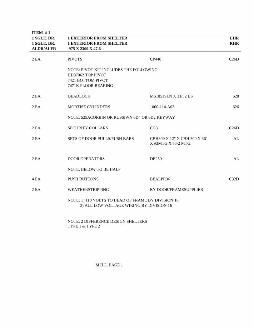
ITEM # 1 1 SGLE. DR. 1 EXTERIOR FROM SHELTER
LHR
1 SGLE. DR. 1 EXTERIOR FROM SHELTER
RHR ALDR/ALFR 975 X 2300 X 47.6
2 EA. PIVOTS CP440 C26D NOTE: PIVOT KIT INCLUDES THE FOLLOWING HD87062 TOP PIVOT 7421 BOTTOM PIVOT 7471K FLOOR BEARING
2 EA. DEADLOCK MS1851SLN X 31/32 BS 628 2 EA. MORTISE CYLINDERS 1000-114-A03 626 NOTE: 525ACORBIN OR RUSSIWN 6D4 OR 6D2 KEYWAY 2 EA. SECURITY COLLARS CG3 C26D 2 EA. SETS OF DOOR PULLS/PUSH BARS CBH300 X 12" X CBH 300 X 36"
X #3MTG X #3-2 MTG. AL
2 EA. DOOR OPERATORS DE250 AL NOTE: BELOW TO BE HALF 4 EA. PUSH BUTTONS BEALPR36 C32D 2 EA. WEATHERSTRIPPING BY DOOR/FRAMESUPPLIER NOTE: 1) 110 VOLTS TO HEAD OF FRAME BY DIVISION 16 2) ALL LOW VOLTAGE WIRING BY DIVISION 16
NOTE: 2 DIFFERENCE DESIGN SHELTERS TYPE 1 & TYPE 2
M.H.L. PAGE 1
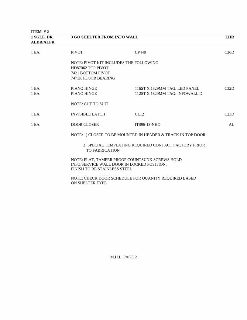
ITEM # 2 1 SGLE. DR. 3 GO SHELTER FROM INFO WALL LHR ALDR/ALFR
1 EA. PIVOT CP440 C26D NOTE: PIVOT KIT INCLUDES THE FOLLOWING HD87062 TOP PIVOT 7421 BOTTOM PIVOT 7471K FLOOR BEARING 1 EA. PIANO HINGE 116ST X 1829MM TAG: LED PANEL C32D 1 EA. PIANO HINGE 112ST X 1829MM TAG: INFOWALL D NOTE: CUT TO SUIT 1 EA. INVISIBLE LATCH CL12 C23D 1 EA. DOOR CLOSER ITS96-13-NHO AL NOTE: 1) CLOSER TO BE MOUNTED IN HEADER & TRACK IN TOP DOOR 2) SPECIAL TEMPLATING REQUIRED CONTACT FACTORY PRIOR TO FABRICATION
NOTE: FLAT, TAMPER PROOF COUNTSUNK SCREWS HOLD
INFO/SERVICE WALL DOOR IN LOCKED POSITION. FINISH TO BE STAINLESS STEEL
NOTE: CHECK DOOR SCHEDULE FOR QUANITY REQUIRED BASED ON SHELTER TYPE
M.H.L. PAGE 2
gh3 architecture Section 08 71 13 GO Shelter Designs AUTOMATIC DOOR EQUIPMENT Page 1
1 General 1.1 SECTION INCLUDES
.1 Design, labour, Products, tool, equipment and services necessary for automatic door equipment work for prefabricated shelters in accordance with the Contract Documents.
1.2 REFERENCES
.1 ANSI/BHMA A156.19, Power Assist and Low-Energy Power-Operated Doors. 1.3 DESIGN REQUIREMENTS
.1 Design handicap door system comprising of low energy power operator with optional push and go door system as defined in ANSI/BHMA A156.19. Power operator to be installed into top of door frame.
.2 Design system operator to conform to AODA requirements.
1.4 SUBMITTALS
.1 Product data: Submit duplicate copies of manufacturer's Product data in accordance with the Conditions of the Contract indicating performance criteria, compliance with appropriate reference standard(s), characteristics, limitations, trouble-shooting protocol, transportation, storage, handling and installation requirements.
.2 Shop drawings: Submit shop drawings in accordance with the Conditions of the
Contract indicating all connections, attachments, reinforcing, anchorage and location of exposed fastenings.
1.5 EXTENDED WARRANTY
.1 Submit an extended warranty for automatic door equipment in accordance with General Conditions, except that warranty period is extended to 2 years. .1 Warrant against failure to meet design criteria and requirements. .2 Coverage: Complete replacement including affected adjacent Work.
Section 08 71 13 gh3 architecture AUTOMATIC DOOR EQUIPMENT GO Shelter Designs Page 2
2 Products 2.1 ACCEPTABLE MANUFACTURER(S) AND SYSTEM(S)
.1 Operator: Electro-mechanical operator. >Dorma ED 250' by Dorma Group or approved alternative. Provide button style BEA, 10LPR36 or approved equivalent.
2.2 REQUIREMENTS
.1 Functional Requirements: .1 Equipment shall be designed to operate specified swing doors. .2 Opening Speed:
.1 Door shall be field adjusted to back check as required in Table 1 of ANSI/BHMA A156.19.
.2 Opening speed to fully open shall be 3 seconds or quicker.
.2 Hold Open: Door shall be field adjusted to remain fully open for not less then 5 seconds or more than 30 seconds during winter months. Door to allow for adjustment to remain open and only close upon activation of button during summer months.
.3 Closing Speed:
.1 Doors shall be field adjusted to close 90o to 10o in 3 seconds or longer as required in Table 1 of ANSI/BHMA A156.19.
.2 Doors shall close from 10o to fully closed in not less than 1.5 seconds.
.3 Force required to prevent door from opening or closing shall not exceed 66 N (14.8 lbs).
.4 During power failure, doors shall open with manual pressure not exceeding 11.3 kg at point 25 mm from latch edge of door.
.5 Doors shall be equipped with signs visible from either side, instructing user as to operation and function of door.
.4 Requirements:
.1 Provide header complete with full housing, finish shall match door frame finish.
.2 Locations of automatic door operators to conform to requirements of the Ontario Building Code (OBC).
.3 Operator shall be activated by stainless steel push button switches on either side as indicated. Size to be as indicated on drawings.
.4 Switches shall bear universal handicap logo visible to all types of traffic.
gh3 architecture Section 08 71 13 GO Shelter Designs AUTOMATIC DOOR EQUIPMENT Page 3
2.3 SHOP INSTALLATION
.1 Install automatic door operators, controls and accessories for doors indicated in accordance with reviewed shop drawings and manufacturer written instructions.
.2 Installation of automatic door operators to be in accordance with requirements of the
Ontario Building Code (OBC).
.3 Doors shall operate manually as though equipped with manual door closers, without damage to automatic door components, in event of power failure or in event of power termination.
.4 Co-ordinate this work with Section 08 56 88.
.5 Power supply to each door operator and wiring shall be provided by Division 26 -
Electrical. Make connections at operators and at control panel and supply and install each electrical work between operators and activating controls. Comply with requirements of Division 26 - Electrical. All wiring shall be concealed and where exposed shall be run in conduit. Location of exposed wiring shall be subject to Consultant's approval.
3 Execution 3.1 INSTALLATION
.1 Installation of prefabricated structure to be in accordance with reviewed shop drawings.
3.2 ADJUSTMENT
.1 Test and adjust operators and controls smooth and proper operation. END OF SECTION
gh3 architecture Section 08 80 00 GO Shelter Designs GLAZING Page 1
1 General 1.1 SECTION INCLUDES
.1 Design, labour, Products, equipment, tools, and services necessary for glass and glazing Work for prefabricated shelters in accordance with the Contract Documents.
1.2 REFERENCES
.1 ASTM C920, Specification for Elastomeric Joint Sealants.
.2 ASTM D2240, Test Method for Rubber Property - Durometer Hardness.
.3 CAN/CGSB-12.1-M, Tempered or Laminated Safety Glass.
.4 CAN/CGSB-12.20-M, Structural Design of Glass for Buildings.
.5 Glass Association of North America (GANA) Glazing Manual. 1.3 DESIGN REQUIREMENTS
.1 Glass Design: .1 Design glass using a probability of breakage of 8 lites per 1000 at the first
application of design load. .2 Design glass to CAN/CGSB-12.20-M. Perform stress analysis. Design units to
accommodate live, dead, lateral, wind, seismic, handling, transportation, and erection loads.
.3 Perform a thermal stress analysis on each glass unit with Low-E coating and provide heat strengthening and/or tempered units as necessary to prevent thermal breakage.
.2 Structural Glazing:
.1 Carry out design of structural silicone joints by rational analysis including all movements specified herein. Maximum stress shall not exceed 138 kPa (20 psi) in tension or shear for short term loading. Maximum stress in shear for long term loading due to the dead load of glass shall not exceed 7 kPa (1 psi) or the limit imposed by sealant manufacturer, whichever is less.
.2 The joint shall be essentially rectangular in shape and shall include no internal corners which could precipitate tearing or create high local stresses.
.3 Single Source Responsibility for Sealants, Gaskets and Other Glazing Accessories: In order to ensure consistent quality of performance, provide all glazing sealants and seals from a single manufacturer.
Section 08 80 00 gh3 architecture GLAZING GO Shelter Designs Page 2
.4 Preconstruction Compatibility and Adhesion Testing: Submit to sealant manufacturer, samples of each glass, gasket, glazing accessory and glass-framing member that will contact or affect glazing sealants for compatibility and adhesion testing. Schedule submission of test samples to provide sufficient time for testing and analysis of results to prevent delay in the progress of work.
.3 Limit glass deflection to flexural limit of glass with full recovery of glazing materials.
1.4 SUBMITTALS
.1 Shop drawings: Submit shop drawings in accordance with the Conditions of the Contract for fabrication and erection of glazing elements indicating materials, thicknesses, finishes, connections, joints, method of anchorage, number of anchors, supports, reinforcement, details, and accessories.
.2 Samples:
.1 Submit following samples in accordance with the Conditions of the Contract.
.2 Submit one sample of each type of glass. .1 300 x 300 mm of each glass type with film applied.
.3 Silicone sealant in grey and clear colours.
.4 Certificates: Submit manufacturer's certification that glass and glazing materials are compatible.
.3 Submit compatibility and adhesion test reports from sealant manufacturer indicating
that glazing materials were tested for compatibility and adhesion with glazing sealants. Include sealant manufacturer=s interpretation of test results relative to sealant performance and recommendations for primers and substrate preparation needed for adhesion.
1.5 QUALITY ASSURANCE
.1 Installers qualifications: Perform Work of this Section by a company that has a minimum of five years proven experience in the installation of glazing units of a similar size and nature.
2 Products 2.1 ACCEPTABLE MANUFACTURERS
.1 Glass manufacturers:
gh3 architecture Section 08 80 00 GO Shelter Designs GLAZING Page 3
.1 AGC Flat Glass.
.2 Cardinal Glass Industries.
.3 Guardian Industries.
.4 Pilkington.
.5 PPG Industries Ltd.
.6 Verrage Glass and Mirror Inc.
.7 Viracon Inc. 2.2 MATERIALS
.1 All materials under Work of this Section, including but not limited to, primers, coatings, sealers, sealants, adhesives and cleaners are to have low VOC content limits.
.2 Tempered glass (TGL): CAN/CGSB-12.1-M, Type 2, Class B, Category II, clear,
minimum 10 mm thick.
.3 Low iron glass (LITG): CAN/CGSB-12.1-M, clear, tempered, glazing quality, minimum 6 mm thick, low iron content, colourless; >Ultra White Low Iron= by Guardian Industries, >Starphire Ultra Clear Glass= by PPG or >low-Iron Glass= by AGC.
.4 Ceramic frit coating: Ceramic frit coating applied to backside of glass. Ceramic frit:
opaque white colour in coverage as indicated on drawings, screen transferred to glass surface and heat cured. >Silk-Screen, Viraspan Design' by Viracon or approved equal.
.5 Glass Film:
.1 Distraction decal to match S1.1 in GO Transit=s Static Signage Catalogue. Application pattern as indicated in GO Transit Catalogue.
.2 Automatic door signs: to match A7.14 in GO Transit=s Signage Catalogue. Application pattern as indicated on drawings.
.3 Push/Pull door signs: to match A7.11 in GO Transit=s Signage Catalogue. Application pattern as indicated on drawings.
.6 Low-E coating: High performance pyrolytic low-E coating. Apply low-E coating to
interior surface unless otherwise indicated or recommended by the coating manufacturer. >Energy Advantage= by Pilkington or approved alternative.
.7 Glazing types:
.1 Type GL1: 10 mm thick TGL clear with low E coating on inside surface. For use at GO Shelter walls.
.2 Type GL2: 10 mm thick TGL clear. For use at GO Shelter walls.
Section 08 80 00 gh3 architecture GLAZING GO Shelter Designs Page 4
.3 Type GL3: 6 mm thick LITG with ceramic frit as indicated. For use at info wall display panels.
.4 Type GL4: 13 mm thick TGL clear with low E coating on inside surface. For use at GO Shelter doors.
.8 Glazing and rebate primers, sealants, sealers, and cleaners: Compatible with each
other. Type as recommended by glass manufacturer.
.9 Glazing sealant: Silicone sealant as recommended by glazing manufacturer.
.10 Glazing Sealant (Structural Glazing): .1 Silicone, One Part in accordance with ASTM C920, Type S or M, Grade NS,
Class 25. .2 Structural glazing tensile bead: >Spectrem 2 Sealant= by Tremco or >Dow
795' by Dow Corning. .3 Structural glazing weather bead: >Spectrem 2 Sealant= by Tremco or >Dow
795' by Dow Corning. .4 Structural glazing (factory glazed): Two-part, neutral cure silicone sealant,
>Proglaze ll= by Tremco or >Dow 983' by Dow Corning. .5 Colour: Grey and clear as approved by Consultant and Metrolinx.
.11 Heel & toe bead: Silicone sealant as recommended by glazing manufacturer.
.12 Glazing gasket: >Visionstrip= by Tremco Ltd., extruded composite glazing seal in
grey colour, size as recommended by manufacturer.
.13 Glazing tape: >Polyshim II= glazing tape EPDM shim.
.14 Glazing splines: Silicone, extruded shape to suit glazing channel retaining slot, colour as selected.
.15 Setting Block (Structural Glazing): Silicone setting blocks with Shore, Type A
durometer hardness of 85, plus or minus 5 to ASTM D2240, sized to suit glazing method, glass unit weight and area.
.16 Edge blocks: EPDM, 60-70 Shore A Durometer hardness, sized with 3 mm clearance
from glass edge and spanning glass thickness(es). Capable of withstanding weight of glass unit, self adhesive on face.
.17 Glass presence markers: Easily removable, non-residue depositing.
.18 Screws, bolts and fasteners: Type 304 stainless steel.
gh3 architecture Section 08 80 00 GO Shelter Designs GLAZING Page 5
2.3 FABRICATION
.1 Verify glazing dimensions on Site.
.2 Clearly label each glass lite with maker's name and glass type. Ensure labels are easily removable, non-residue depositing type. Do not remove labels until after Work is accepted by Consultant.
.3 Fabricate glazing not less than 3 mm smaller than rebate size in either dimension;
allow for edge spacers, shims, and setting blocks as necessary.
.4 Work shall have smooth finished surfaces free from distortion and defects detrimental to appearance and performance.
.5 Carefully make and fit details. Take special care with exposed finished Work to
produce a neat and correct appearance to the Consultant's acceptance.
.6 Grind and polish a 1.5 mm arris to all vertical edges of glazing. 2.4 SHOP INSTALLATION
.1 Provide glazing in accordance with IGMA recommendations. Provide continuous contact between glazing tapes and gasket to the glazing.
.2 Install glazing to the Work of Sections 08 56 88. .3 Provide neat, straight sight lines. Trim excess glazing material flush with top of
stops and fixed leg of frames.
.4 Remove protective coatings, glazing stops, clean rebate and glass contact surfaces with solvent, wipe dry.
.5 Apply primer/sealer to contact surfaces, prior to glazing.
.6 Apply glazing tape as per manufacturer=s instructions including recommended corner
sealant.
.7 Use setting blocks at 1/4 points and spacers to centre glass unit in frame.
.8 Install glazing in accordance with reviewed shop drawings and manufacturer's written instructions. Install glazing with full contact and adhesion at perimeter. Maintain edge clearance recommended by glass manufacturer.

Section 08 80 00 gh3 architecture GLAZING GO Shelter Designs Page 6
.9 Apply a continuous heel bead of sealant around perimeter of inboard lite of the sealed unit and the metal framing.
.10 Re-install glazing stops ensuring continuous contact and rattle-free installation. Do
not distort glass. Trim tape protruding more than 2 mm above stop.
.11 Install glazing gasket in accordance with manufacturer=s recommendations.
.12 Do not cut or abrade tempered, heat treated, or coated glass.
.13 Install glass presence markers in two cross stripes extending from diagonal corners. Maintain markers until final clean-up.
.14 Remove, dispose of, and replace broken, cut, abraded glass, and defective glass
including but not limited to production dimples, >tiger-stripping=, chips, cracks, etc.
.15 Exterior glass (Structural Glazing): Glaze units in accordance with reviewed shop drawings and in accordance with manufacturer=s written instructions.
.16 Interior glass: Glaze interior glass using glazing gasket glazing tape.
.17 Interior Infowall Display Panels: Adhere glazing to substrate using adhesive approved
for use.
.18 Glass Film .1 Install glass film with adhesive, applied in accordance with film
manufacturer's instructions. .2 Place without air bubbles, creases or visible distortion. .3 Fit tight to glass perimeter with razor cut edge.
3 Execution 3.1 INSTALLATION
.1 Installation of prefabricated structure to be in accordance with reviewed shop drawings.
3.2 CLEANING
.1 Remove labels, protective material, and glass presence markers from prefinished surfaces.

gh3 architecture Section 08 80 00 GO Shelter Designs GLAZING Page 7
.2 Clean glass surfaces with cleaning agents and methods in accordance with Manufacturer=s written instructions.
.3 Do not wash glass film for 30 days after installation.
.4 Do not use bristle brushes on glass film.
END OF SECTION
SPECIFICATION
of
MECHANICAL WORK
for
Go Shelter Designs
Ontario
for
Metrolinx
MECHANICAL CONSULTANT Integral Group 2nd Floor, 1214 9th Avenue S.E. Calgary, AB T2G 0T1
PROJECT NO: 210007.000
ISSUED FOR 100% DETAILED DESIGN
ISSUE DATE: 2016-07-26

Integral Group Section 23 00 00 GO Shelter Designs TABLE OF CONTENTS Page 1
Table of Contents Section Description 23 83 00 Radiant Heating and Cooling Systems
Integral Group Section 23 83 00 GO Shelter Designs RADIANT HEATING SYSTEMS Page 1
1 General
1.1 Related Work
.1 This Specification Section forms part of Contract Documents and are to be read, interpreted and coordinated with other parts.
1.2 Scope
.1 Supply and install radiant heaters as shown on the drawings and as specified herein.
1.3 Quality Assurance
.1 Codes and Standards: Comply with local and provincial laws and ordinances.
.2 All radiant heat system components shall be provided by one Manufacturer.
.3 Provide 25 year Manufacturer’s guarantee against manufacturing defects on materials installed within ceiling or topping. Installer shall provide five year warranty against faulty workmanship.
.4 Radiant surface temperatures shall not exceed 91°F (33°C) at design heat output.
1.4 Submittals
.1 Shop Drawings: .1 Submit Manufacturer’s technical product data and installation instructions for
approval before ordering and/or installing any of the system components. .2 Radiant system installer shall provide detailed shop drawings including the
following information: .1 Miscellaneous accessories such as air vents, flow meters, drain valves and
pressure bypass. .2 Electrical requirements and locations of power supply required; transformers.
1.5 Coordination
.1 Verify exact location, space requirements and access details for manifolds and control unit before start of work.
2 Products
2.1 Radiant Infrared Heaters - Electric
.1 Standard of Acceptance: Infratech W2524.
.2 Minimum Requirements. .1 Narrow beam comfort heater. .2 Metal sheath tubular element. .3 Highly-corrosion resistance. .4 2500 watts, 208V input. .5 8530 BTU output.
.3 Accessories: .1 Mesh guard to protect heater against accidental contact and vandalism
2.2 Heater controls
Integral Group Section 23 83 00 GO Shelter Designs RADIANT HEATING SYSTEMS Page 2
.1 Delay Off timing relay .1 24VAC input voltage .2 240VAC, 11A output power .3 When input power turns on output load will turn on. .4 Output load will remain on for 10 minutes after input power turns off.
.2 Low voltage thermostat .1 Exterior rated thermostat. .2 24VAC operating voltage. .3 Thermostat to transmit 24V signal when space temperature is below 0oC.
.3 Low voltage push button .1 Exterior rated pushbutton .2 24VAC operating voltage .3 Momentary contact switch. .4 Internal LED illumination .5 Light will turn on when heater is activated, will be off when heater is inactive. .6 Acceptable manufacturer:
.1 Sprecher + Schuh catalogue # D7M-LE4PN5RX10
.2 Approved alternate.
3 Execution
3.1 Installation
.1 Install equipment to manufacturer’s instructions and recommendations.
3.2 Testing, Balancing and Warranties
.1 Contractor is responsible to make all necessary adjustments to the radiant heating and cooling system equipment and controls and shall ensure system is properly tested, balanced and operating.
END OF SECTION 23 83 00
SPECIFICATION
of
ELECTRICAL WORK
for
GO Shelter Designs Ontario
for
Metrolinx
ELECTRICAL CONSULTANT Integral Group Suite 800 - 111 Peter Street Toronto, ON M5V 2H1
PROJECT NO: 210007.000
ISSUED FOR 100% DETAILED DESIGN
ISSUE DATE: 2016-07-26
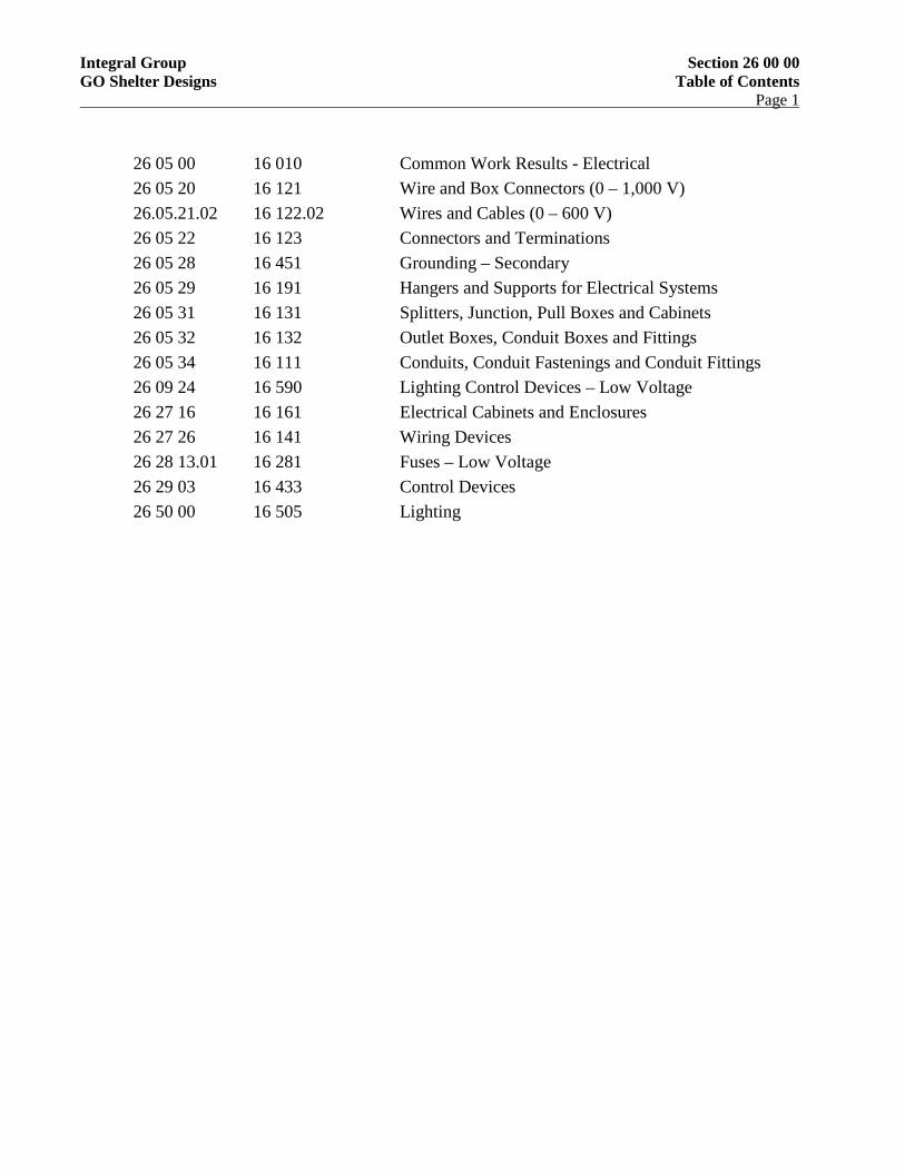
Integral Group Section 26 00 00 GO Shelter Designs Table of Contents Page 1
26 05 00 16 010 Common Work Results - Electrical 26 05 20 16 121 Wire and Box Connectors (0 – 1,000 V) 26.05.21.02 16 122.02 Wires and Cables (0 – 600 V) 26 05 22 16 123 Connectors and Terminations 26 05 28 16 451 Grounding – Secondary 26 05 29 16 191 Hangers and Supports for Electrical Systems 26 05 31 16 131 Splitters, Junction, Pull Boxes and Cabinets 26 05 32 16 132 Outlet Boxes, Conduit Boxes and Fittings 26 05 34 16 111 Conduits, Conduit Fastenings and Conduit Fittings 26 09 24 16 590 Lighting Control Devices – Low Voltage 26 27 16 16 161 Electrical Cabinets and Enclosures 26 27 26 16 141 Wiring Devices 26 28 13.01 16 281 Fuses – Low Voltage 26 29 03 16 433 Control Devices 26 50 00 16 505 Lighting
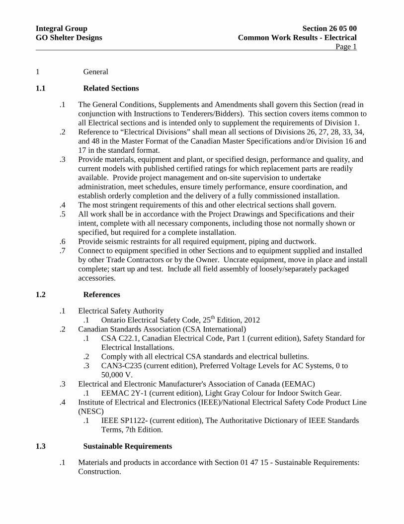
Integral Group Section 26 05 00 GO Shelter Designs Common Work Results - Electrical Page 1
1 General
1.1 Related Sections
.1 The General Conditions, Supplements and Amendments shall govern this Section (read in conjunction with Instructions to Tenderers/Bidders). This section covers items common to all Electrical sections and is intended only to supplement the requirements of Division 1.
.2 Reference to “Electrical Divisions” shall mean all sections of Divisions 26, 27, 28, 33, 34, and 48 in the Master Format of the Canadian Master Specifications and/or Division 16 and 17 in the standard format.
.3 Provide materials, equipment and plant, or specified design, performance and quality, and current models with published certified ratings for which replacement parts are readily available. Provide project management and on-site supervision to undertake administration, meet schedules, ensure timely performance, ensure coordination, and establish orderly completion and the delivery of a fully commissioned installation.
.4 The most stringent requirements of this and other electrical sections shall govern.
.5 All work shall be in accordance with the Project Drawings and Specifications and their intent, complete with all necessary components, including those not normally shown or specified, but required for a complete installation.
.6 Provide seismic restraints for all required equipment, piping and ductwork.
.7 Connect to equipment specified in other Sections and to equipment supplied and installed by other Trade Contractors or by the Owner. Uncrate equipment, move in place and install complete; start up and test. Include all field assembly of loosely/separately packaged accessories.
1.2 References
.1 Electrical Safety Authority .1 Ontario Electrical Safety Code, 25th Edition, 2012
.2 Canadian Standards Association (CSA International) .1 CSA C22.1, Canadian Electrical Code, Part 1 (current edition), Safety Standard for
Electrical Installations. .2 Comply with all electrical CSA standards and electrical bulletins. .3 CAN3-C235 (current edition), Preferred Voltage Levels for AC Systems, 0 to
50,000 V. .3 Electrical and Electronic Manufacturer's Association of Canada (EEMAC)
.1 EEMAC 2Y-1 (current edition), Light Gray Colour for Indoor Switch Gear. .4 Institute of Electrical and Electronics (IEEE)/National Electrical Safety Code Product Line
(NESC) .1 IEEE SP1122- (current edition), The Authoritative Dictionary of IEEE Standards
Terms, 7th Edition.
1.3 Sustainable Requirements
.1 Materials and products in accordance with Section 01 47 15 - Sustainable Requirements: Construction.
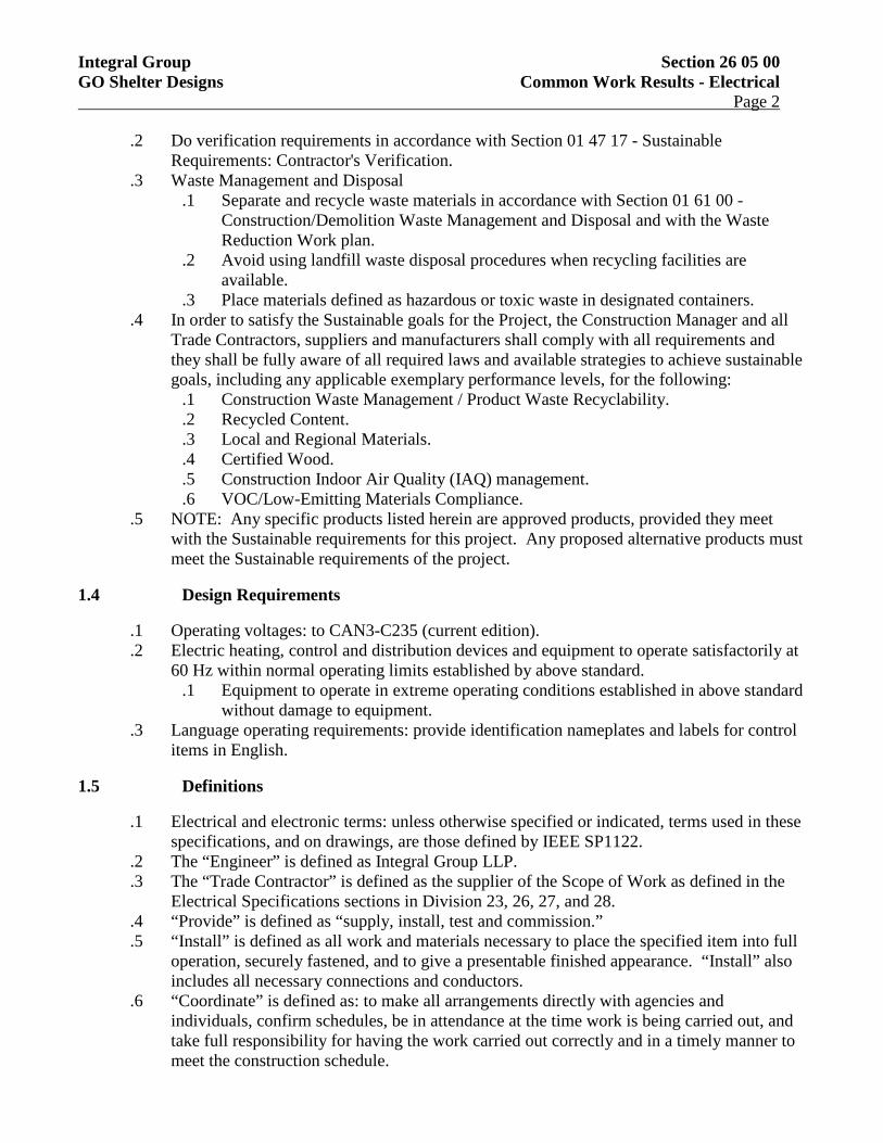
Integral Group Section 26 05 00 GO Shelter Designs Common Work Results - Electrical Page 2
.2 Do verification requirements in accordance with Section 01 47 17 - Sustainable Requirements: Contractor's Verification.
.3 Waste Management and Disposal .1 Separate and recycle waste materials in accordance with Section 01 61 00 -
Construction/Demolition Waste Management and Disposal and with the Waste Reduction Work plan.
.2 Avoid using landfill waste disposal procedures when recycling facilities are available.
.3 Place materials defined as hazardous or toxic waste in designated containers. .4 In order to satisfy the Sustainable goals for the Project, the Construction Manager and all
Trade Contractors, suppliers and manufacturers shall comply with all requirements and they shall be fully aware of all required laws and available strategies to achieve sustainable goals, including any applicable exemplary performance levels, for the following:
.1 Construction Waste Management / Product Waste Recyclability.
.2 Recycled Content.
.3 Local and Regional Materials.
.4 Certified Wood.
.5 Construction Indoor Air Quality (IAQ) management.
.6 VOC/Low-Emitting Materials Compliance. .5 NOTE: Any specific products listed herein are approved products, provided they meet
with the Sustainable requirements for this project. Any proposed alternative products must meet the Sustainable requirements of the project.
1.4 Design Requirements
.1 Operating voltages: to CAN3-C235 (current edition).
.2 Electric heating, control and distribution devices and equipment to operate satisfactorily at 60 Hz within normal operating limits established by above standard.
.1 Equipment to operate in extreme operating conditions established in above standard without damage to equipment.
.3 Language operating requirements: provide identification nameplates and labels for control items in English.
1.5 Definitions
.1 Electrical and electronic terms: unless otherwise specified or indicated, terms used in these specifications, and on drawings, are those defined by IEEE SP1122.
.2 The “Engineer” is defined as Integral Group LLP.
.3 The “Trade Contractor” is defined as the supplier of the Scope of Work as defined in the Electrical Specifications sections in Division 23, 26, 27, and 28.
.4 “Provide” is defined as “supply, install, test and commission.”
.5 “Install” is defined as all work and materials necessary to place the specified item into full operation, securely fastened, and to give a presentable finished appearance. “Install” also includes all necessary connections and conductors.
.6 “Coordinate” is defined as: to make all arrangements directly with agencies and individuals, confirm schedules, be in attendance at the time work is being carried out, and take full responsibility for having the work carried out correctly and in a timely manner to meet the construction schedule.
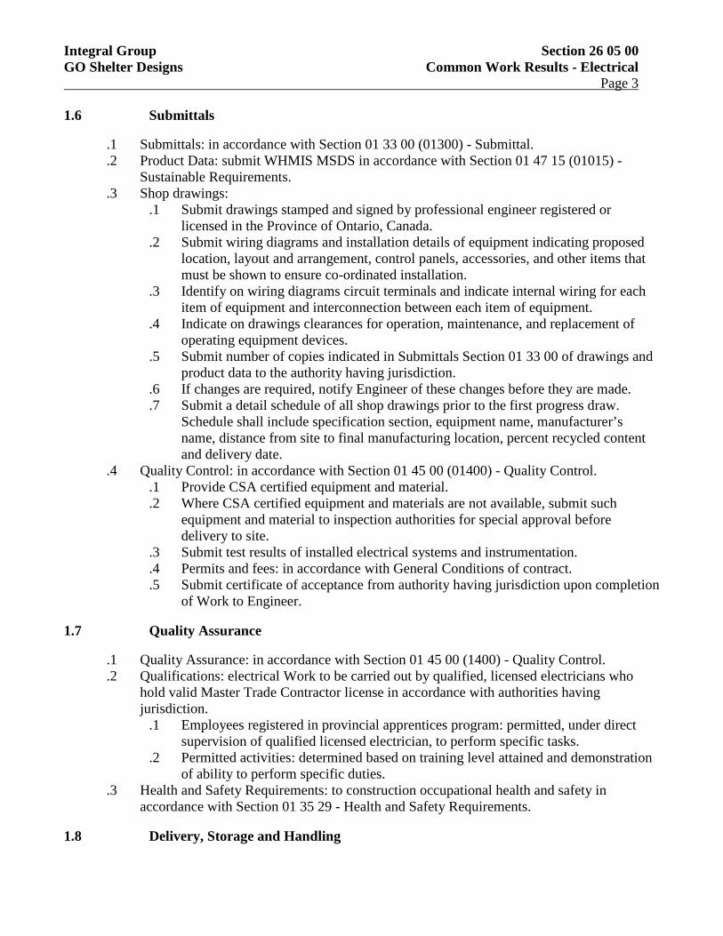
Integral Group Section 26 05 00 GO Shelter Designs Common Work Results - Electrical Page 3
1.6 Submittals
.1 Submittals: in accordance with Section 01 33 00 (01300) - Submittal.
.2 Product Data: submit WHMIS MSDS in accordance with Section 01 47 15 (01015) - Sustainable Requirements.
.3 Shop drawings: .1 Submit drawings stamped and signed by professional engineer registered or
licensed in the Province of Ontario, Canada. .2 Submit wiring diagrams and installation details of equipment indicating proposed
location, layout and arrangement, control panels, accessories, and other items that must be shown to ensure co-ordinated installation.
.3 Identify on wiring diagrams circuit terminals and indicate internal wiring for each item of equipment and interconnection between each item of equipment.
.4 Indicate on drawings clearances for operation, maintenance, and replacement of operating equipment devices.
.5 Submit number of copies indicated in Submittals Section 01 33 00 of drawings and product data to the authority having jurisdiction.
.6 If changes are required, notify Engineer of these changes before they are made.
.7 Submit a detail schedule of all shop drawings prior to the first progress draw. Schedule shall include specification section, equipment name, manufacturer’s name, distance from site to final manufacturing location, percent recycled content and delivery date.
.4 Quality Control: in accordance with Section 01 45 00 (01400) - Quality Control. .1 Provide CSA certified equipment and material. .2 Where CSA certified equipment and materials are not available, submit such
equipment and material to inspection authorities for special approval before delivery to site.
.3 Submit test results of installed electrical systems and instrumentation.
.4 Permits and fees: in accordance with General Conditions of contract.
.5 Submit certificate of acceptance from authority having jurisdiction upon completion of Work to Engineer.
1.7 Quality Assurance
.1 Quality Assurance: in accordance with Section 01 45 00 (1400) - Quality Control.
.2 Qualifications: electrical Work to be carried out by qualified, licensed electricians who hold valid Master Trade Contractor license in accordance with authorities having jurisdiction.
.1 Employees registered in provincial apprentices program: permitted, under direct supervision of qualified licensed electrician, to perform specific tasks.
.2 Permitted activities: determined based on training level attained and demonstration of ability to perform specific duties.
.3 Health and Safety Requirements: to construction occupational health and safety in accordance with Section 01 35 29 - Health and Safety Requirements.
1.8 Delivery, Storage and Handling
Integral Group Section 26 05 00 GO Shelter Designs Common Work Results - Electrical Page 4
.1 Material Delivery Schedule: provide Engineer with schedule of all materials within 2 weeks after award of Contract. Progress claims will not be reviewed until updated schedules are provided.
.2 Construction/Demolition Waste Management and Disposal: separate waste materials for reuse and recycling in accordance with Section 01 74 21 - Construction Waste Management.
1.9 System Start-up
.1 Instruct Engineer and operating personnel in operation, care and maintenance of systems, system equipment and components.
1.10 Operating Instructions
.1 Provide for each system and principal item of equipment as specified in technical sections for use by operation and maintenance personnel.
.2 Operating instructions to include following: .1 Wiring diagrams, control diagrams, and control sequence for each principal system
and item of equipment. .2 Start up, proper adjustment, operating, lubrication, and shutdown procedures. .3 Safety precautions. .4 Procedures to be followed in event of equipment failure. .5 Other items of instruction as recommended by manufacturer of each system or item
of equipment. .3 Post instructions where directed. .4 For operating instructions exposed to weather, provide weather-resistant materials or
weatherproof enclosures. .5 Ensure operating instructions will not fade when exposed to sunlight and are secured to
prevent easy removal or peeling.
1.11 Permits and Fees
.1 Submit to Electrical Review Department, Local Fire Authorities and Supply Authority the necessary number of drawings and specifications for examination and approval prior to commencement of work. Obtain all required permits and pay all fees.
.2 Arrange for review of all Work by the authorities having jurisdiction. On completion of the Work, furnish final unconditional certificates of approval by the inspecting authorities.
1.12 Equipment Restraint
.1 It is the entire responsibility of the equipment manufacturers to design their equipment so that the strength and anchorage of internal components of the equipment exceeds the force level used to restrain and anchor the unit itself to the supporting structure.
1.13 Seismic Analysis and Provisions
.1 Install electrical systems with adequate structural support to withstand seismic forces in accordance with Section 4.1.8 of the National Building Code, and Province, Territory or Municipality of the project.
Integral Group Section 26 05 00 GO Shelter Designs Common Work Results - Electrical Page 5
.2 Retain a structural engineer licensed in the Province or Territory of the project to perform a review of the proposed electrical installation and prepare installation documents indicating all required seismic supports, bracings and fastenings. These documents shall be sealed and signed by the structural engineer and submitted as part of the shop drawing package prior to rough-in work commencing on site.
.3 Equipment to be indicated in the structural design documents shall include but not be limited to: suspended transformers, bus ducts, cable trays, suspended conduit runs, free standing distribution equipment such as switchboards and motor control centres, and suspended lighting fixtures.
.4 Verify the Facility is classified as “Normal” with an “Importance Factor of 1.0” as referenced in 4.1.8.5 (1) of the National Building Code and Province, Territory or Municipality of the project.
.5 Refer to seismic risk reduction of operational and functional components (OFCs) of building S832-06 and meet all requirements.
.6 Provide confirmation in writing, signed and sealed by the structural engineer, at completion of project that the electrical installation is in general compliance with the structural installation drawings submitted with the shop drawing package.
.7 All light fixtures shall be provided with independent chain supports that are fastened to the structure of the Shelter.
.8 The trade contractor shall be solely responsible for the full scope of this work. Include all costs of structural design, materials and site review in Bid Price.
1.14 Drawings and Measurements
.1 Drawings are generally diagrammatic and are intended to indicate the scope and general arrangement of work and are not detailed installation drawings. Do not scale the drawings. Obtain accurate dimensions from the Architectural and Structural drawings.
.2 Consult the Architectural drawings and details for exact locations of fixtures and equipment. Obtain this information from the Engineer where definite locations are not indicated.
.3 Take field measurements where equipment and material dimensions are dependent upon shelter dimensions.
.4 Where imperial units have been indicated in brackets [ ] following the requirements in SI units, the conversion is approximate and provided for convenience. The SI units shall govern.
1.15 Project Coordination
.1 Check drawings of all trades to verify space and headroom limitations for work to be installed. Coordinate work with all trades and make changes to facilitate a satisfactory installation. Make no deviations from the design intent involving extra cost to the Owner without the Engineer’s written approval.
.2 The drawings indicate the general location and route to be followed by the electrical services. Where details are not shown on the drawings or only shown diagrammatically, the services shall be installed in such a way as to conserve headroom and interfere as little as possible with the free use of space through which they pass. Service lines shall run parallel to shelter lines. All services in the ceiling shall be kept as tight as possible to beams or other limiting members at high level. All electrical services shall be coordinated
Integral Group Section 26 05 00 GO Shelter Designs Common Work Results - Electrical Page 6
in elevation to ensure that they are concealed in the ceiling or structural space provided unless detailed otherwise on drawings.
.3 Work out jointly all interference problems on the site and coordinate all work before fabricating or installing any material or equipment. Where necessary, produce interference/coordination drawings showing exact locations of electrical systems or equipment within service areas, shafts and the ceiling space. Distribute copies of the final interference/coordination drawings to the Architect and Engineer and all affected parties.
.4 Ensure that all materials and equipment fit into the allotted spaces and that all equipment can be properly serviced and replaced, if and when required. Advise the Engineer of space problems before installing any material or equipment. Demonstrate to the Engineer on completion of the work that all equipment installed can be properly, safely serviced and replaced, if and when required.
1.16 Tender Inquiries
.1 All Trade Contractor queries during the tender period shall be made in writing to the Engineer. Trade Contractor queries will be collected and suitable addenda will be issued for clarification. No verbal information will be considered valid or issued by the Engineer’s office during tender. All tender queries may be emailed, faxed, mailed or couriered to the Engineer’s office. No telephone queries will be answered.
1.17 Examination
.1 Visit the site before preparing the tender and examine all existing conditions. No extra cost will be considered for any misunderstanding of the work to be done resulting from failure to visit the site.
.2 Examine the documents for details of work included. Obtain a written clarification in the event of conflict within the specification, between the specification and the drawing, or in the drawing. Obtain written clarification from the Engineer if work affecting the installation is not clear. Where this is not done in advance, allow in the tender sum for providing the more costly alternative.
1.18 Responsibilities
.1 Ensure that equipment does not transmit noise and/or vibration to other parts of the shelter, as a result of poor installation practices.
.2 Where the Contract Documents do not contain sufficient information for the proper selection of equipment for bidding, notify the Engineer during the tendering period. If clarification is not obtainable, allow for the most expensive arrangement. Failure to do this shall not relieve the Trade Contractor of responsibility to provide the intended equipment.
.3 Protect equipment and material from the weather, moisture, dust and physical damage.
.4 Cover equipment openings and open ends of conduits, piping and pull boxes as work progresses. Failure to do so will result in the Trade being required to adequately clean or replace materials and equipment at no extra cost to the Owner.
.5 Protect all existing services encountered. Obtain instructions from the Engineer when existing services require relocation or modification.
.6 Refinish damaged or marred factory finish to factory finish.

Integral Group Section 26 05 00 GO Shelter Designs Common Work Results - Electrical Page 7
.7 The specifications and drawings form an integral part of the Contract Documents. Neither the drawings nor the specifications shall be used alone. Work omitted from the drawings but mentioned or reasonably implied in the specifications, and vice versa, shall be considered as properly and sufficiently specified and shall be provided. Misinterpretation of any requirement of either plans or specifications shall not relieve the Trade Contractor of the responsibility of properly completing his trade to the approval of the Engineer.
1.19 Standard of Acceptance
.1 Standard of Acceptance means that the item named and specified by the manufacturer and/or catalogue number forms part of the specification and sets standard regarding performance, quality of material and workmanship and when used in conjunction with a reference standard, shall be deemed to supplement the standard.
.2 Where two or more manufacturers are listed, the manufacturer’s name shown first or underlined or shown with a model name and/or number was used in preparing the base design. Tenders may be based on any one of those named, provided that they meet every aspect of the base design and every aspect of the drawings and specifications.
.3 Where other than the first named or the underlined manufacturer or scheduled/specified manufacturer is selected or approved, include for the cost of any resulting work (both under this Division and other Divisions) and any necessary redesign of installation or structure. Submit redesign drawings for review with Shop Drawings. Maintain installation, access and servicing clearances. Equipment/materials shall not exceed the available space limitations. Redesign drawings shall be to scale and of a standard equal to the Project Drawings.
.4 A visible manufacturer’s nameplate shall indicate manufacturer’s name, model number, serial number, capacity data, electrical characteristics and approval stamps.
1.20 Progress Claim and Change Order Breakdowns
.1 Ten (10) days after the award of contract, submit price breakdowns.
.2 In particular cases, more detail may be necessary to properly assess a change order or progress claims. This additional information could include all suppliers and all trade contractors when requested by the Engineer. Provide details for each section of the electrical work listed for each separate electrical change order.
.3 Mark-up information is required for change orders but is optional on the original tender price.
.4 Progress claims will not be certified nor payment made beyond 90% of the overall Electrical contract until commissioning and verification of the systems are complete. This procedure is to allow for any necessary deficiency holdbacks on items which do not become apparent until the systems are commissioned.
1.21 Warranty
.1 Use of installed equipment during construction shall not shorten or alter the warranty period, as specified in Division 1.
.2 Take note of any extended warranties specified.
Integral Group Section 26 05 00 GO Shelter Designs Common Work Results - Electrical Page 8
.3 Furnish a written warranty stating that all work executed under this Division will be free from defects of material and workmanship for a period of one (1) year from the date of substantial performance.
.4 Promptly investigate any electrical or control malfunction and repair or replace all such defective work and all other damages thereby which becomes defective during the time of the warranty.
1.22 Substantial Performance Requirements
.1 Refer to each section in specifications for detailed requirements.
.2 Before the Engineer is requested to make an review for substantial performance of the work:
.1 Commission all systems and prove out all components, interlocks and safety devices.
.2 Submit a letter certifying that all work is complete for the intended use, operational, clean and all required submissions have been completed.
.3 A complete list of incomplete or deficient items shall be provided. If, in the opinion of the Engineer, this list indicates the project is excessively incomplete, a substantial completion review will not be performed.
.3 The work will not be considered to be ready for use or substantially complete until the following requirements have been met:
.1 All reported deficiencies have been corrected.
.2 Operating and Maintenance Manuals completed.
.3 “As Built” Record Drawing ready for review.
.4 Systems Commissioning has been completed and has been verified by the Engineer.
.5 All demonstrations to the Owner have been completed. .4 Engineer’s Letters of Assurance will not be issued until the following requirements have
been met: .1 All items listed in .1 above have been completed or addressed. .2 Certificate of Penetrations through Separations .3 Provincial or City Electrical Review – Certificate of Review. .4 Seismic Engineer’s Letter of Assurance and Final Review Report. .5 Certificate of Substantial Performance. .6 Signed off copy of Engineer’s Final Review Report. .7 Fire Alarm Verification.
.5 Deficiency Holdback and Deficiency Reviews .1 Work under this Division which is still outstanding when substantial performance is
certified will be considered deficient and a sum equal to at least twice the estimated cost of completing that work will be held back.
.2 It is expected that outstanding work will be completed in an expeditious manner and the entire holdback sum will be retained until the requirements for Total Performance of work have been met and verified.
2 Products
2.1 Materials and Equipment
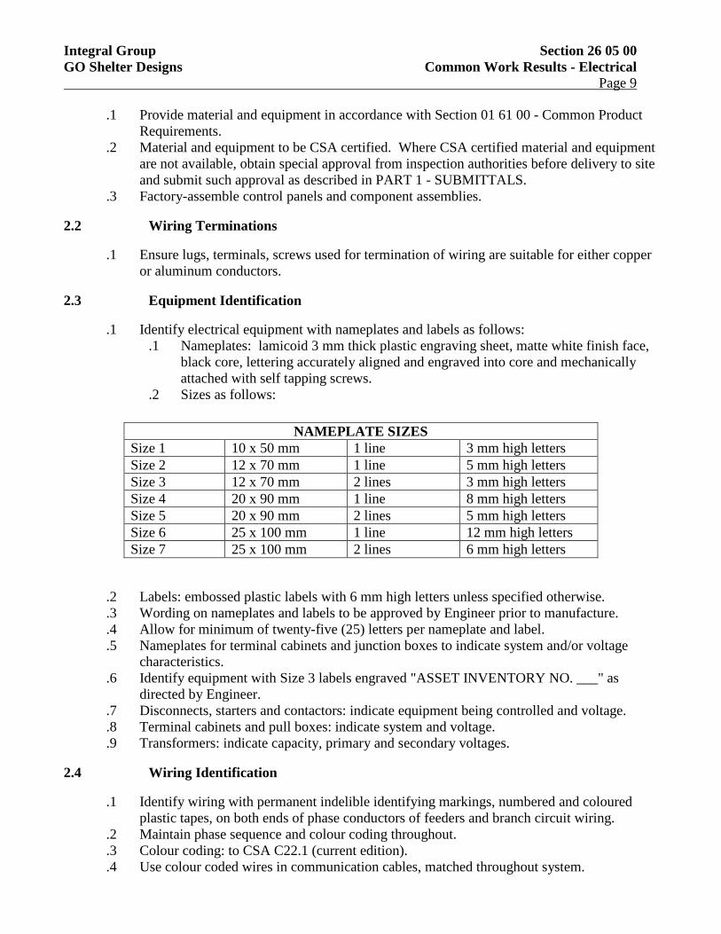
Integral Group Section 26 05 00 GO Shelter Designs Common Work Results - Electrical Page 9
.1 Provide material and equipment in accordance with Section 01 61 00 - Common Product Requirements.
.2 Material and equipment to be CSA certified. Where CSA certified material and equipment are not available, obtain special approval from inspection authorities before delivery to site and submit such approval as described in PART 1 - SUBMITTALS.
.3 Factory-assemble control panels and component assemblies.
2.2 Wiring Terminations
.1 Ensure lugs, terminals, screws used for termination of wiring are suitable for either copper or aluminum conductors.
2.3 Equipment Identification
.1 Identify electrical equipment with nameplates and labels as follows: .1 Nameplates: lamicoid 3 mm thick plastic engraving sheet, matte white finish face,
black core, lettering accurately aligned and engraved into core and mechanically attached with self tapping screws.
.2 Sizes as follows:
NAMEPLATE SIZES Size 1 10 x 50 mm 1 line 3 mm high letters Size 2 12 x 70 mm 1 line 5 mm high letters Size 3 12 x 70 mm 2 lines 3 mm high letters Size 4 20 x 90 mm 1 line 8 mm high letters Size 5 20 x 90 mm 2 lines 5 mm high letters Size 6 25 x 100 mm 1 line 12 mm high letters Size 7 25 x 100 mm 2 lines 6 mm high letters
.2 Labels: embossed plastic labels with 6 mm high letters unless specified otherwise.
.3 Wording on nameplates and labels to be approved by Engineer prior to manufacture.
.4 Allow for minimum of twenty-five (25) letters per nameplate and label.
.5 Nameplates for terminal cabinets and junction boxes to indicate system and/or voltage characteristics.
.6 Identify equipment with Size 3 labels engraved "ASSET INVENTORY NO. ___" as directed by Engineer.
.7 Disconnects, starters and contactors: indicate equipment being controlled and voltage.
.8 Terminal cabinets and pull boxes: indicate system and voltage.
.9 Transformers: indicate capacity, primary and secondary voltages.
2.4 Wiring Identification
.1 Identify wiring with permanent indelible identifying markings, numbered and coloured plastic tapes, on both ends of phase conductors of feeders and branch circuit wiring.
.2 Maintain phase sequence and colour coding throughout.
.3 Colour coding: to CSA C22.1 (current edition).
.4 Use colour coded wires in communication cables, matched throughout system.
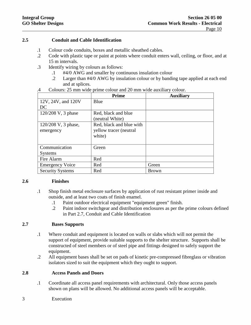
Integral Group Section 26 05 00 GO Shelter Designs Common Work Results - Electrical Page 10
2.5 Conduit and Cable Identification
.1 Colour code conduits, boxes and metallic sheathed cables.
.2 Code with plastic tape or paint at points where conduit enters wall, ceiling, or floor, and at 15 m intervals.
.3 Identify wiring by colours as follows: .1 #4/0 AWG and smaller by continuous insulation colour .2 Larger than #4/0 AWG by insulation colour or by banding tape applied at each end
and at splices. .4 Colours: 25 mm wide prime colour and 20 mm wide auxiliary colour.
Prime Auxiliary 12V, 24V, and 120V DC
Blue
120/208 V, 3 phase Red, black and blue (neutral White)
120/208 V, 3 phase, emergency
Red, black and blue with yellow tracer (neutral white)
Communication Systems
Green
Fire Alarm Red Emergency Voice Red Green Security Systems Red Brown
2.6 Finishes
.1 Shop finish metal enclosure surfaces by application of rust resistant primer inside and outside, and at least two coats of finish enamel.
.1 Paint outdoor electrical equipment "equipment green" finish.
.2 Paint indoor switchgear and distribution enclosures as per the prime colours defined in Part 2.7, Conduit and Cable Identification
2.7 Bases Supports
.1 Where conduit and equipment is located on walls or slabs which will not permit the support of equipment, provide suitable supports to the shelter structure. Supports shall be constructed of steel members or of steel pipe and fittings designed to safely support the equipment.
.2 All equipment bases shall be set on pads of kinetic pre-compressed fibreglass or vibration isolators sized to suit the equipment which they ought to support.
2.8 Access Panels and Doors
.1 Coordinate all access panel requirements with architectural. Only those access panels shown on plans will be allowed. No additional access panels will be acceptable.
3 Execution
Integral Group Section 26 05 00 GO Shelter Designs Common Work Results - Electrical Page 11
3.1 Installation
.1 Do complete installation in accordance with CSA C22.1 except where specified otherwise.
.2 Do overhead and underground systems in accordance with CSA C22.3 No.1 except where specified otherwise.
3.2 Nameplates and Labels
.1 Ensure manufacturer's nameplates, CSA labels and identification nameplates are visible and legible after equipment is installed.
.2 Provide nameplates to the following equipment at a minimum: .1 Panelboards .2 Identification of pull and junction boxes .3 Colour identification of wiring .4 Identification of receptacles and fire alarm devices .5 Equipment identification schedule
3.3 Location of Devices
.1 Locate outlets in accordance with Section 26 05 32 - Outlet Boxes, Conduit Boxes and Fittings.
.2 Do not install outlets back-to-back in wall; allow minimum 150 mm horizontal clearance between boxes.
.3 Change location of devices at no extra cost or credit, providing distance does not exceed 3000 mm, and information is given before installation.
.4 Locate light switches on latch side of doors.
.5 Locate disconnect devices in mechanical and elevator machine rooms on latch side of floor.
3.4 Mounting Heights
.1 Mounting height of equipment is from finished floor to centreline of equipment unless specified or indicated otherwise.
.2 If mounting height of equipment is not specified or indicated, verify before proceeding with installation.
.3 Install electrical equipment at following heights unless indicated otherwise. .1 Local switches: 1400 mm. .2 Wall receptacles:
.1 General: 300 mm. .3 Communications outlets: 300 mm. .4 Wall mounted telephone and interphone outlets: 1500 mm.
3.5 Coordination of Protective Devices
.1 Ensure circuit protective devices such as overcurrent trips, relays and fuses are installed to required values and settings.
3.6 Field Quality Control

Integral Group Section 26 05 00 GO Shelter Designs Common Work Results - Electrical Page 12
.1 Load Balance: .1 Measure phase current to panelboards with normal loads (lighting) operating at time
of acceptance; adjust branch circuit connections as required to obtain best balance of current between phases and record changes.
.2 Measure phase voltages at loads and adjust transformer taps to within 2% of rated voltage of equipment.
.3 Provide upon completion of work, load balance report as directed in PART 1 - SUBMITTALS: phase and neutral currents on panelboards, dry-core transformers and motor control centres, operating under normal load, as well as hour and date on which each load was measured, and voltage at time of test.
.2 Conduct following tests: .1 Power generation and distribution system including phasing, voltage, grounding
and load balancing. .2 Circuits originating from branch distribution panels. .3 Lighting and its control. .4 Motors, heaters and associated control equipment including sequenced operation of
systems where applicable. .5 Insulation resistance testing:
.1 Megger circuits, feeders and equipment up to 350 V with a 500 V instrument.
.2 Megger 350-600 V circuits, feeders and equipment with a 1000 V instrument.
.3 Check resistance to ground before energizing. .3 Carry out tests in presence of Engineer. .4 Provide instruments, meters, equipment and personnel required to conduct tests during and
at conclusion of project. .5 Manufacturer's Field Services:
.1 Obtain written report from manufacturer verifying compliance of Work, in handling, installing, applying, protecting and cleaning of product and submit Manufacturer's Field Reports as described in PART 1 - SUBMITTALS.
.2 Provide manufacturer's field services consisting of product use recommendations and periodic site visits for review of product installation in accordance with manufacturer's instructions.
.3 Schedule site visits, to review Work, as directed in PART 1 - QUALITY ASSURANCE.
.6 Reports: .1 Provide written reports in a timely manner upon completion of testing and load
balance. Indicate date and hour tested.
3.7 Cleaning
.1 Clean and touch up surfaces of shop-painted equipment scratched or marred during shipment or installation, to match original paint.
.2 Clean and prime exposed non-galvanized hangers, racks and fastenings to prevent rusting. END OF SECTION 26 05 00
Integral Group Section 26 05 20 GO Shelter Designs Wire and Box Connectors (0-1,000V) Page 1
1 General
1.1 Section Includes
.1 Materials and installation for wire and box connectors.
1.2 Related Sections
.1 This section of the specification forms part of the contract documents and is to be read, interepreted and coordinated with all other parts.
.2 Section 01 74 21 - Construction/Demolition Waste Management and Disposal.
1.3 References
.1 Electrical Safety Authority .1 Ontario Electrical Safety Code
.2 Canadian Standards Association (CSA International): .1 CAN/CSA-C22.2No.18 (current edition), Outlet Boxes, Conduit Boxes, Fittings
and Associated Hardware. .2 CSA C22.2No.65 (current edition), Wire Connectors.
.3 National Electrical Manufacturers Association (NEMA).
1.4 Sustainable Requirements
.1 Materials and products in accordance with Section 01 47 15 - Sustainable Requirements: Construction.
.2 Do verification requirements in accordance with Section 01 47 17 - Sustainable Requirements: Contractor's Verification.
.3 Waste Management and Disposal .1 Separate and recycle waste materials in accordance with Section 01 61 00 -
Construction/Demolition Waste Management and Disposal and with the Waste Reduction Work plan.
.2 Avoid using landfill waste disposal procedures when recycling facilities are available.
.3 Place materials defined as hazardous or toxic waste in designated containers. .4 In order to satisfy the Sustainable goals for the Project, the Construction Manager and all
Trade Contractors, suppliers and manufacturers shall comply with all requirements and they shall be fully aware of all required laws and available strategies to achieve sustainable goals, including any applicable exemplary performance levels, for the following:
.1 Construction Waste Management / Product Waste Recyclability.
.2 Recycled Content.
.3 Local and Regional Materials.
.4 Certified Wood.
.5 Construction Indoor Air Quality (IAQ) management.
.6 VOC/Low-Emitting Materials Compliance. .5 NOTE: Any specific products listed herein are approved products, provided they meet
with the Sustainable requirements for this project. Any proposed alternative products must meet the Sustainable requirements of the project.
Integral Group Section 26 05 20 GO Shelter Designs Wire and Box Connectors (0-1,000V) Page 2
1.5 Submittals
.1 Submittals: in accordance with Section 01 33 00 - Submittal Procedures.
.2 Product Data: .1 Provide manufacturer’s printed product literature, specifications and data sheets,
and include product characteristics, performance criteria, physical size, finish and limitations.
.2 Submit WHMIS MSDS - Material Safety Data Sheets in accordance with Section 01 47 15 - Sustainable Requirements: Construction and Section 02 81 01 - Hazardous Materials and include: product characteristics, performance criteria, physical size, horsepower, watt rating, limitations and finish
.3 Delivery, Storage and Handling .1 Deliver, store, handle and protect materials in accordance with Section 01 61 00 -
Common Product Requirements. .2 Deliver, store and handle materials in accordance with manufacturer's written
instructions. .3 Handle materials with suitable lifting equipment. .4 Store materials in heated, dry, weather-protected enclosure
2 Products
2.1 Material
.1 Pressure type wire connectors shall be in accordance with CSA C22.2 No.65, with current carrying parts of copper sized to fit copperconductors as required.
.2 Fixture type splicing connectors shall be in accordance with CSA C22.2 No.65, with current carrying parts of copper sized to fit copper conductors 10 AWG or less.
.3 Bushing stud connectors shall be NEMA type to consist of: .1 Connector body and stud clamp for stranded copper conductors. .2 Clamp for stranded copper conductors. .3 Stud clamp bolts. .4 Bolts for copper conductors. .5 Sized for conductors as indicated.
.4 Clamps or connectors for armoured cable, flexible conduit, as required shall be in accordance with CAN/CSA-C22.2 No.18.
3 Execution
3.1 Installation
.1 Remove insulation carefully from ends of conductors and: .1 Apply coat of zinc joint compound on aluminum conductors prior to installation of
connectors. .2 Install mechanical pressure type connectors and tighten screws with appropriate
compression tool recommended by manufacturer. Installation shall meet secureness tests in accordance with CSA C22.2 No.65.
.3 Install fixture type connectors and tighten. Replace insulating cap.
.4 Install bushing stud connectors in accordance with NEMA requirements.
Integral Group Section 26 05 20 GO Shelter Designs Wire and Box Connectors (0-1,000V) Page 3
3.2 Maintenance – Clearances
.1 Provide clearance around systems, equipment and components for observation of operation, review, servicing, maintenance and as recommended by manufacturer and Ontario Electrical Safety Code.
3.3 Cleaning
.1 Proceed in accordance with Section 01 74 11 – Cleaning.
.2 On completion and verification of performance of installation, remove surplus materials, excess materials, rubbish, tools and equipment.
END OF SECTION 26 05 20
Integral Group Section 26 05 21.02 GO Shelter Designs Wires and Cables (0-600V) Page 1
1 General
1.1 Section Includes
.1 Materials and installation for Wires and Cables (0 – 600 V)
1.2 Related Sections
.1 This section of the specification forms part of the contract documents and is to be read, interpreted, and coordinated with all other parts.
1.3 References
.1 Canadian Standards Association (CSA International) .1 CSA C22.1 (current edition), Canadian Electric Code, Part 1.
1.4 Sustainable Requirements
.1 Materials and products in accordance with Section 01 47 15 - Sustainable Requirements: Construction.
.2 Do verification requirements in accordance with Section 01 47 17 - Sustainable Requirements: Contractor's Verification.
.3 Waste Management and Disposal .1 Separate and recycle waste materials in accordance with Section 01 61 00 -
Construction/Demolition Waste Management and Disposal and with the Waste Reduction Work plan.
.2 Avoid using landfill waste disposal procedures when recycling facilities are available.
.3 Place materials defined as hazardous or toxic waste in designated containers. .4 In order to satisfy the Sustainable goals for the Project, the Construction Manager and all
Trade Contractors, suppliers and manufacturers shall comply with all requirements and they shall be fully aware of all required laws and available strategies to achieve sustainable goals, including any applicable exemplary performance levels, for the following:
.1 Construction Waste Management / Product Waste Recyclability.
.2 Recycled Content.
.3 Local and Regional Materials.
.4 Certified Wood.
.5 Construction Indoor Air Quality (IAQ) management.
.6 VOC/Low-Emitting Materials Compliance. .5 NOTE: Any specific products listed herein are approved products, provided they meet
with the Sustainable requirements for this project. Any proposed alternative products must meet the Sustainable requirements of the project.
1.5 Submittals
.1 Submittals: in accordance with Section 01 33 00 - Submittal Procedures.
.2 Product Data:
Integral Group Section 26 05 21.02 GO Shelter Designs Wires and Cables (0-600V) Page 2
.1 Provide manufacturer’s printed product literature, specifications and data sheets, and include product characteristics, performance criteria, physical size, finish and limitations.
.2 Submit WHMIS MSDS - Material Safety Data Sheets in accordance with Section 01 47 15 - Sustainable Requirements: Construction and Section 02 81 01 - Hazardous Materials and include: product characteristics, performance criteria, physical size, horsepower, watt rating, limitations and finish
.3 Provide product data in accordance with Section 01 33 00 - Submittal Procedures.
1.6 Delivery, Storage and Handling
.1 Deliver, store, handle and protect materials in accordance with Section 01 61 00 - Common Product Requirements.
.2 Deliver, store and handle materials in accordance with manufacturer's written instructions.
.3 Handle materials with suitable lifting equipment.
.4 Store materials in heated, dry, weather-protected enclosure
2 Products
2.1 Shelter Wires
.1 All conductors shall be copper unless requested in the contract documents.
.2 Conductors shall be stranded for 12 AWG and larger. Minimum size shall be 12 AWG.
.3 Copper conductors shall be sized as indicated, with 600 V insulation of cross-linked thermosetting polyethylene material rated 90° C, jacketed.
2.2 Armoured Cables
.1 Conductors shall be bare copper Class B, size as indicated.
.2 Insulation: Cross-linked polyethylene type RW90
.3 Armour shall be interlocking type fabricated from aluminum strip.
.4 Outer jacket: Low-temperature, moisture and sunlight resistant PVC
.5 Connectors shall be anti-short connectors.
.6 Approved manufacturer: .1 Texcan
2.3 Control Cables
.1 Type shall be 600 V stranded annealed copper conductors, sizes as indicated: .1 Insulation shall be cross-linked polyethylene type RW90 (x-link). .2 Shielding shall be braid. .3 Overall covering shall be thermoplastic jacket.
3 Execution
3.1 General Cable Installation
.1 Install cable in trenches in accordance with Section 33 71 73.02 - Underground Electrical Service.
Integral Group Section 26 05 21.02 GO Shelter Designs Wires and Cables (0-600V) Page 3
.2 Lay cable in cable trays in accordance with Section 26 05 36 - Cable Trays for Electrical Systems.
.3 Terminate cables in accordance with Section 26 05 20 - Wire and Box Connectors - (0 - 1,000 V).
.4 Cable Colour Coding shall be in accordance with Section 26 05 00 Common Work Results for Electrical.
.5 Conductor length for parallel feeders to be identical.
.6 Lace or clip groups of feeder cables at distribution centres, pull boxes, and termination points.
.7 Wiring in walls shall be typical drop or loop vertically from above to better facilitate future renovations. Generally wiring from below and horizontal wiring in walls to be avoided unless indicated.
.8 Branch circuit wiring for surge suppression receptacles and permanently wired computer and electronic equipment to be two-wire circuits only, i.e. common neutrals not permitted.
.9 Provide numbered wire collars for control wiring. Numbers to correspond to control shop drawing legend. Obtain wiring diagram for control wiring.
.10 Branch circuit wiring shall not use shared neutrals.
3.2 Installation of Shelter Wires
.1 Install wiring as follows: .1 In conduit systems in accordance with Section 26 05 34 - Conduits, Conduit
Fastenings and Conduit Fittings. .2 In underground ducts in accordance with Section 33. .3 In underfloor distribution system in accordance with Section 21. .4 In cellular floor raceways in accordance with Section 21. .5 In surface and lighting fixture raceways in accordance with Section 26. .6 In wireways and auxiliary gutters in accordance with Section 21. .7 Overhead service conductors in accordance with Section 21.
3.3 Installation of Armoured Cables
.1 Group cables wherever possible on channels.
3.4 Installation of Control Cables
.1 Install control cables in conduit.
.2 Ground control cable shield.
3.5 Cleaning
.1 Proceed in accordance with Section 01 74 11 – Cleaning.
.2 On completion and verification of performance of installation, remove surplus materials, excess materials, rubbish, tools and equipment.
3.6 Field Quality Control
.1 Perform tests in accordance with Section 26 05 00 - Common Work Results for Electrical.
.2 Perform tests before energizing electrical system.

Integral Group Section 26 05 21.02 GO Shelter Designs Wires and Cables (0-600V) Page 4
END OF SECTION 26 05 21.02
Integral Group Section 26 05 22 GO Shelter Designs Connectors and Terminations Page 1
1 General
1.1 Section Includes
.1 Materials and installation for connectors and terminations.
1.2 Related Sections
.1 This section of the specification forms part of the contract documents and is to be read, interpreted and coordinated with all other parts.
.2 Section 01 33 00 - Submittal Procedures.
.3 Section 01 74 21 - Construction/Demolition Waste Management and Disposal.
.4 Section 26 05 33 - Raceway and Boxes for Electrical Systems.
1.3 References
.1 Electrical Safety Authority .1 Ontario Electrical Safety Code
.2 Canadian Standards Association (CSA International): .1 CSA C22.2 No.41 (current edition), Grounding and Bonding Equipment.
1.4 Sustainable Requirements
.1 Materials and products in accordance with Section 01 47 15 - Sustainable Requirements: Construction.
.2 Do verification requirements in accordance with Section 01 47 17 - Sustainable Requirements: Contractor's Verification.
.3 Waste Management and Disposal .1 Separate and recycle waste materials in accordance with Section 01 61 00 -
Construction/Demolition Waste Management and Disposal and with the Waste Reduction Work plan.
.2 Avoid using landfill waste disposal procedures when recycling facilities are available.
.3 Place materials defined as hazardous or toxic waste in designated containers. .4 In order to satisfy the Sustainable goals for the Project, the Construction Manager and all
Trade Contractors, suppliers and manufacturers shall comply with all requirements and they shall be fully aware of all required laws and available strategies to achieve sustainable goals, including any applicable exemplary performance levels, for the following:
.1 Construction Waste Management / Product Waste Recyclability.
.2 Recycled Content.
.3 Local and Regional Materials.
.4 Certified Wood.
.5 Construction Indoor Air Quality (IAQ) management.
.6 VOC/Low-Emitting Materials Compliance. .5 NOTE: Any specific products listed herein are approved products, provided they meet
with the Sustainable requirements for this project. Any proposed alternative products must meet the Sustainable requirements of the project.
Integral Group Section 26 05 22 GO Shelter Designs Connectors and Terminations Page 2
1.5 Submittals
.1 Submittals: in accordance with Section 01 33 00 - Submittal Procedures.
.2 Product Data: .1 Provide manufacturer’s printed product literature, specifications and data sheets,
and include product characteristics, performance criteria, physical size, finish and limitations.
.2 Submit WHMIS MSDS - Material Safety Data Sheets in accordance with Section 01 47 15 - Sustainable Requirements: Construction and Section 02 81 01 - Hazardous Materials and include: product characteristics, performance criteria, physical size, horsepower, watt rating, limitations and finish
.3 Submit product data in accordance with Section 01 33 00 - Submittal Procedures.
1.6 Delivery, Storage and Handling
.1 Deliver, store, handle and protect materials in accordance with Section 01 61 00 - Common Product Requirements.
.2 Deliver, store and handle materials in accordance with manufacturer's written instructions.
.3 Handle materials with suitable lifting equipment.
.4 Store materials in heated, dry, weather-protected enclosure
1.7 Certificates
.1 Obtain inspection certificate of compliance covering high voltage stress coning from inspection authority and include it with as-built drawings.
2 Products
2.1 Connectors and Terminations
.1 Copper compression connectors to CSA C22.2 as required sized for conductors.
.2 Contact aid for aluminum cables where applicable.
.3 Four -way joint boxes dry location type in accordance with Section 26 05 33 - Raceway and Boxes for Electrical Systems.
3 Execution
3.1 Installation
.1 Install stress cones, terminations, and splices in accordance with manufacturer's instructions.
.2 Bond and ground as required to CSA C22.2No.41.
3.2 Maintenance – Clearances
.1 Provide clearance around systems, equipment and components for observation of operation, review, servicing, maintenance and as recommended by manufacturer and Ontario Electrical Safety Code.
3.3 Cleaning

Integral Group Section 26 05 22 GO Shelter Designs Connectors and Terminations Page 3
.1 Proceed in accordance with Section 01 74 11 – Cleaning.
.2 On completion and verification of performance of installation, remove surplus materials, excess materials, rubbish, tools and equipment.
END OF SECTION 26 05 22
Integral Group Section 26 05 28 GO Shelter Designs Grounding - Secondary Page 1
1 General
1.1 Section Includes
.1 Materials and installation for secondary grounding.
1.2 Related Sections
.1 This section of the Specification forms part of the contract documents and is to be read, interpreted and coordinated with all other parts.
1.3 References
.1 American National Standards Institute (ANSI)/Institute of Electrical and Electronics Engineers (IEEE)
.2 Canadian Standards Association, (CSA International)
1.4 Sustainable Requirements
.1 Materials and products in accordance with Section 01 47 15 - Sustainable Requirements: Construction.
.2 Do verification requirements in accordance with Section 01 47 17 - Sustainable Requirements: Contractor's Verification.
.3 Waste Management and Disposal .1 Separate and recycle waste materials in accordance with Section 01 61 00 -
Construction/Demolition Waste Management and Disposal and with the Waste Reduction Work plan.
.2 Avoid using landfill waste disposal procedures when recycling facilities are available.
.3 Place materials defined as hazardous or toxic waste in designated containers. .4 In order to satisfy the Sustainable goals for the Project, the Construction Manager and all
Trade Contractors, suppliers and manufacturers shall comply with all requirements and they shall be fully aware of all required laws and available strategies to achieve sustainable goals, including any applicable exemplary performance levels, for the following:
.1 Construction Waste Management / Product Waste Recyclability.
.2 Recycled Content.
.3 Local and Regional Materials.
.4 Certified Wood.
.5 Construction Indoor Air Quality (IAQ) management.
.6 VOC/Low-Emitting Materials Compliance. .5 NOTE: Any specific products listed herein are approved products, provided they meet
with the Sustainable requirements for this project. Any proposed alternative products must meet the Sustainable requirements of the project.
1.5 Delivery, Storage and Handling
.1 Deliver, store, handle and protect materials in accordance with Section 01 61 00 - Common Product Requirements.
Integral Group Section 26 05 28 GO Shelter Designs Grounding - Secondary Page 2
.2 Deliver, store and handle materials in accordance with manufacturer's written instructions.
.3 Handle materials with suitable lifting equipment.
.4 Store materials in heated, dry, weather-protected enclosure
1.6 Testing Requirements
.1 Perform ground continuity and resistance test using method appropriate to site conditions. Measure ground grid resistance.
.2 Any third party testing agency costs for the testing and reporting shall be included in the Electrical Division base tender and shall be carried out by a pre-approved testing agency.
2 Products
2.1 Material
.1 Clamps for grounding of conductor: size as required to electrically conductive underground water pipe.
.2 Copper conductor: minimum 6 m long for each electrode; bare, stranded, copper, size as indicated.
.3 Rod electrodes: galvanized steel 19 mm diameter by 3 m long.
.4 Plate electrodes: galvanized steel, surface area 0.2 m2, 1.6 mm thick.
.5 Insulated grounding conductors: green, type RWU90 XLPE.
.6 Ground bus: copper, size as indicated, complete with insulated supports, fastenings, connectors.
.7 Non-corroding accessories necessary for grounding system, type, size, material as indicated, including but not necessarily limited to:
.1 Grounding and bonding bushings.
.2 Protective type clamps.
.3 Bolted type conductor connectors.
.4 Thermit welded type conductor connectors.
.5 Bonding jumpers, straps.
.6 Pressure wire connectors.
3 Execution
3.1 Installation – General
.1 Install complete permanent, continuous grounding system including, electrodes, conductors, connectors, accessories. Where EMT is used, run ground wire in conduit.
.2 Install connectors in accordance with manufacturer's instructions.
.3 Protect exposed grounding conductors from mechanical injury.
.4 Make buried connections, and connections to conductive water main, electrodes, using permanent mechanical connectors or inspectable wrought copper compression connectors to ANSI/IEEE 837.
.5 Use mechanical connectors for grounding connections to equipment provided with lugs.
.6 Soldered joints not permitted.
Integral Group Section 26 05 28 GO Shelter Designs Grounding - Secondary Page 3
.7 Install bonding wire for flexible conduit, connected at both ends to grounding bushing, solderless lug, clamp or cup washer and screw. Neatly cleat bonding wire to exterior of flexible conduit.
.8 Install flexible ground straps for bus duct enclosure joints, where such bonding is not inherently provided with equipment.
.9 Install separate ground conductor to outdoor lighting standards.
.10 Install grounding resistance bank.
.11 Connect shelter structural steel and metal siding to ground by welding copper to steel.
.12 Make grounding connections in radial configuration only, with connections terminating at single grounding point. Avoid loop connections.
.13 Bond single conductor, metallic armoured cables to cabinet at supply end, and provide non-metallic entry plate at load end.
.14 Ground secondary service pedestals.
3.2 Electrodes
.1 Install rod electrodes and make grounding connections.
.2 Bond separate, multiple electrodes together.
.3 Use size 3/0 AWG copper conductors for connections to electrodes.
.4 Make special provision for installing electrodes that will give acceptable resistance to ground value where rock or sand terrain prevails. Ground as indicated.
3.3 Equipment Grounding
.1 Install grounding connections to typical equipment included in, but not necessarily limited to following list. Service equipment, transformers, switchgear, duct systems, frames of motors, motor control centres, starters, control panels, shelter steel work, generators, elevators and escalators, distribution panels, outdoor lighting.
.2 Provide a grounding conductor from the secondary of every distribution transformer to the grounding system. Ground conductor to be sized and installed in accordance with the Ontario Electrical Safety Code.
.3 Provide grounding conductor(s) from all major switchgear to solidly ground the secondary system. This includes equipment located in the main electrical room as well as each sub-electrical room. Grounding conductors are to be sized to Ontario Electrical Safety Code and switchgear manufacturer’s requirements.
3.4 Grounding Bus
.1 Provide a ground bus in the main electrical room. The ground bus shall consist of a suitable length of 50mm x 6mm copper bus mounted on a 25mm insulting standoff. This bus shall be drilled and tapped to receive all the grounding conductors indicated and an engraved nameplate or tag shall be installed above or below individual conductors indicating their function.
.2 Provide a similar ground bus in each sub-electrical room and major mechanical room. Interconnect to the main ground bus with a 3/0 AWG insulated copper grounding conductor that is typically installed with the power feeders.
.3 Provide a similar ground bus in each data and voice equipment room and closet as indicated in “Data & Voice Grounding” clause.
Integral Group Section 26 05 28 GO Shelter Designs Grounding - Secondary Page 4
.4 Ground items of electrical equipment in the electrical room to the ground bus with individual bare stranded copper connections, size 3/0 AWG or as indicated.
.5 Copper or bronze lugs are required for termination of all copper conductors at ground busses.
3.5 Communication Systems
.1 Install home run insulated ground conductor in conduit from the shelter ground bus as follows:
.1 #1/0 AWG to a ground bus in the main telecommunication equipment room.
.2 #2 AWG to a ground bus in the telecommunication equipment room.
.3 #2 AWG to a ground bus in the main telephone equipment room.
.4 #2 AWG to a ground bus in each telephone backboard in equipment rooms/closets. .2 Unless otherwise solidly bonded, bond all data and telephone incoming and outgoing steel
conduits with insulated 1#12 AWG from the nearest “Communication” ground bus.
3.6 Mechanical Equipment Grounding
.1 Provide a #2 ground conductor from the mechanical room ground bus to each MCC.
.2 Provide a #6 ground conductor from the mechanical room ground bus to each VFD.
.3 Ground wires are to be installed in all conduits serving motor feeder circuits and are to extend to ground screws on junction and outlet boxes for bonding.
3.7 Field Quality Control
.1 Perform ground continuity and resistance tests using method appropriate to site conditions and to approval of Engineer and local authority having jurisdiction over installation.
.2 Perform tests before energizing electrical system.
.3 Disconnect ground fault indicator during tests.
3.8 Maintenance – Clearances
.1 Provide clearance around systems, equipment and components for observation of operation, review, servicing, maintenance and as recommended by manufacturer and Ontario Electrical Safety Code.
3.9 Cleaning
.1 Proceed in accordance with Section 01 74 11 – Cleaning.
.2 On completion and verification of performance of installation, remove surplus materials, excess materials, rubbish, tools and equipment.
END OF SECTION 26 05 28
Integral Group Section 26 05 29 GO Shelter Designs Hangers and Supports for Electrical Systems Page 1
1 General
1.1 Section Includes
.1 Material and installation for hangers and supports.
1.2 Related Sections
.1 This section of the Specification forms part of the contract documents and is to be read, interpreted and coordinated with all other parts.
1.3 References
.1 Canadian Standards Association (CSA International)
.2 Ontario Electrical Safety Code
1.4 Sustainable Requirements
.1 Materials and products in accordance with Section 01 47 15 - Sustainable Requirements: Construction.
.2 Do verification requirements in accordance with Section 01 47 17 - Sustainable Requirements: Contractor's Verification.
.3 Waste Management and Disposal .1 Separate and recycle waste materials in accordance with Section 01 61 00 -
Construction/Demolition Waste Management and Disposal and with the Waste Reduction Work plan.
.2 Avoid using landfill waste disposal procedures when recycling facilities are available.
.3 Place materials defined as hazardous or toxic waste in designated containers. .4 In order to satisfy the Sustainable goals for the Project, the Construction Manager and all
Trade Contractors, suppliers and manufacturers shall comply with all requirements and they shall be fully aware of all required laws and available strategies to achieve sustainable goals, including any applicable exemplary performance levels, for the following:
.1 Construction Waste Management / Product Waste Recyclability.
.2 Recycled Content.
.3 Local and Regional Materials.
.4 Certified Wood.
.5 Construction Indoor Air Quality (IAQ) management.
.6 VOC/Low-Emitting Materials Compliance. .5 NOTE: Any specific products listed herein are approved products, provided they meet
with the Sustainable requirements for this project. Any proposed alternative products must meet the Sustainable requirements of the project.
1.5 Submittals
.1 Submittals: in accordance with section 01 33 00 – Submittal Procedures.
.2 Product Data:
Integral Group Section 26 05 29 GO Shelter Designs Hangers and Supports for Electrical Systems Page 2
.1 Provide manufacturer’s printed product literature, specifications and data sheets, and include product characteristics, performance criteria, physical size, finish and limitations.
1.6 Delivery, Storage and Handling
.1 Deliver, store, handle and protect materials in accordance with Section 01 61 00 - Common Product Requirements.
.2 Deliver, store and handle materials in accordance with manufacturer's written instructions.
.3 Handle materials with suitable lifting equipment.
.4 Store materials in heated, dry, weather-protected enclosure
2 Products
2.1 Support Channels
.1 U shape, size 41 x 41 mm, 2.5 mm thick, surface mounted, suspended or set in poured concrete walls and ceilings.
3 Execution
3.1 Installation
.1 Secure equipment to masonry, tile and plaster surfaces with lead anchors.
.2 Secure equipment to poured concrete with expandable inserts.
.3 Support equipment, conduit or cables using clips, spring loaded bolts, cable clamps designed as accessories to basic channel members.
.4 Fasten exposed conduit or cables to shelter construction or support system using straps. .1 One-hole steel straps to secure surface conduits and cables 50 mm and smaller. .2 Two-hole steel straps for conduits and cables larger than 50 mm. .3 Beam clamps to secure conduit to exposed steel work.
.5 Suspended support systems. .1 Support individual cable or conduit runs with 6 mm diameter threaded rods and
spring clips. .2 Support 2 or more cables or conduits on channels supported by 6 mm diameter
threaded rod hangers where direct fastening to shelter construction is impractical. .6 For surface mounting of two or more conduits use channels at 1.5 m on centre spacing. .7 Provide metal brackets, frames, hangers, clamps and related types of support structures
where indicated or as required to support conduit and cable runs. .8 Ensure adequate support for raceways and cables dropped vertically to equipment where
there is no wall support. .9 Do not use wire lashing or perforated strap to support or secure raceways or cables. .10 Do not use supports or equipment installed for other trades for conduit or cable support
except with permission of other trade and approval of Engineer. .11 Install fastenings and supports as required for each type of equipment cables and conduits,
and in accordance with manufacturer's installation recommendations.
3.2 Maintenance – Clearances
Integral Group Section 26 05 29 GO Shelter Designs Hangers and Supports for Electrical Systems Page 3
.1 Provide clearance around systems, equipment and components for observation of operation, review, servicing, maintenance and as recommended by manufacturer and Ontario Electrical Safety Code.
3.3 Cleaning
.1 Proceed in accordance with Section 01 74 11 – Cleaning.
.2 On completion and verification of performance of installation, remove surplus materials, excess materials, rubbish, tools and equipment.
END OF SECTION 26 05 29
Integral Group Section 26 05 31 GO Shelter Designs Splitters, Junction, Pull Boxes and Cabinets Page 1
1 General
1.1 Section Includes
.1 Materials and installation for splitters, junctions, pull boxes and cabinets.
1.2 Related Sections
.1 This section of the Specification forms part of the contract documents and is to be read, interpreted and coordinated with all other parts.
1.3 References
.1 Electrical Safety Authority .1 Ontario Electrical Safety Code
.2 Canadian Standards Association (CSA International) .1 CSA C22.2 No. 76, Splitters. .2 CSA C22.2 No. 40, (Cutout), Junction and pull boxes.
1.4 Sustainable Requirements
.1 Materials and products in accordance with Section 01 47 15 - Sustainable Requirements: Construction.
.2 Do verification requirements in accordance with Section 01 47 17 - Sustainable Requirements: Contractor's Verification.
.3 Waste Management and Disposal .1 Separate and recycle waste materials in accordance with Section 01 61 00 -
Construction/Demolition Waste Management and Disposal and with the Waste Reduction Work plan.
.2 Avoid using landfill waste disposal procedures when recycling facilities are available.
.3 Place materials defined as hazardous or toxic waste in designated containers. .4 In order to satisfy the Sustainable goals for the Project, the Construction Manager and all
Trade Contractors, suppliers and manufacturers shall comply with all requirements and they shall be fully aware of all required laws and available strategies to achieve sustainable goals, including any applicable exemplary performance levels, for the following:
.1 Construction Waste Management / Product Waste Recyclability.
.2 Recycled Content.
.3 Local and Regional Materials.
.4 Certified Wood.
.5 Construction Indoor Air Quality (IAQ) management.
.6 VOC/Low-Emitting Materials Compliance.
.7 NOTE: Any specific products listed herein are approved products, provided they meet with the Sustainable requirements for this project. Any proposed alternative products must meet the Sustainable requirements of the project.
1.5 Submittals
Integral Group Section 26 05 31 GO Shelter Designs Splitters, Junction, Pull Boxes and Cabinets Page 2
.1 Submittals: in accordance with Section 01 33 00 - Submittal Procedures.
.2 Product Data: .1 Provide manufacturer's printed product literature, specifications and datasheet and
include product characteristics, performance criteria, physical size, finish and limitations.
.2 Submit WHMIS MSDS - Material Safety Data Sheets in accordance with Section 01 47 15 - Sustainable Requirements: Construction and Section 02 81 01 - Hazardous Materials and include: product characteristics, performance criteria, physical size, horsepower, watt rating, limitations and finish
1.6 Delivery, Storage and Handling
.1 Deliver, store, handle and protect materials in accordance with Section 01 61 00 - Common Product Requirements.
.2 Deliver, store and handle materials in accordance with manufacturer's written instructions.
.3 Handle materials with suitable lifting equipment.
.4 Store materials in heated, dry, weather-protected enclosure
2 Products
2.1 Junction and Pull Boxes
.1 Construction-welded steel enclosure.
.2 Covers Flush Mounted: 25 mm minimum extension all around.
.3 Covers Surface Mounted: screw-on flat covers.
2.2 Cabinets
.1 Construction: welded sheet steel hinged door, handle, latch and catch
.2 Type E Empty: flush overlapping sides, mounting as indicated.
.3 Type T Terminal: flush overlapping sides mounting as indicated containing 19 mm plywood backboard.
3 Execution .1 .
3.2 Junction, Pull Boxes and Cabinets Installation
.1 Install pull boxes in inconspicuous but accessible locations.
.2 Mount cabinets with top not higher than 2 m above finished floor except where indicated otherwise.
.3 Install terminal block as indicated in Type T cabinets.
.4 Only main junction and pull boxes are indicated. Install additional pull boxes as required by CSA C22.1.
3.3 Identification
.1 Identification Labels: size 2 indicating system name, voltage and phase, or as indicated.

Integral Group Section 26 05 31 GO Shelter Designs Splitters, Junction, Pull Boxes and Cabinets Page 3
3.4 Maintenance – Clearances
.1 Provide clearance around systems, equipment and components for observation of operation, review, servicing, maintenance and as recommended by manufacturer and Ontario Electrical Safety Code.
3.5 Cleaning
.1 Proceed in accordance with Section 01 74 11 – Cleaning.
.2 On completion and verification of performance of installation, remove surplus materials, excess materials, rubbish, tools and equipment.
END OF SECTION 26 05 31
Integral Group Section 26 05 32 GO Shelter Designs Outlet Boxes, Conduit Boxes and Fittings Page 1
1 General
1.1 Section Includes
.1 Materials and installation for outlet boxes, conduit boxes and fittings.
1.2 Related Sections
.1 This section of the Specification forms part of the contract documents and is to be read, interpreted and coordinated with all other parts.
1.3 References
.1 Electrical Safety Authority .1 Ontario Electrical Safety Code
.2 Canadian Standards Association (CSA International) .1 CSA C22.2 No. 18, Outlet boxes, conduit boxes and fittings.
1.4 Sustainable Requirements
.1 Materials and products in accordance with Section 01 47 15 - Sustainable Requirements: Construction.
.2 Do verification requirements in accordance with Section 01 47 17 - Sustainable Requirements: Contractor's Verification.
.3 Waste Management and Disposal .1 Separate and recycle waste materials in accordance with Section 01 61 00 -
Construction/Demolition Waste Management and Disposal and with the Waste Reduction Work plan.
.2 Avoid using landfill waste disposal procedures when recycling facilities are available.
.3 Place materials defined as hazardous or toxic waste in designated containers. .4 In order to satisfy the Sustainable goals for the Project, the Construction Manager and all
Trade Contractors, suppliers and manufacturers shall comply with all requirements and they shall be fully aware of all required laws and available strategies to achieve sustainable goals, including any applicable exemplary performance levels, for the following:
.1 Construction Waste Management / Product Waste Recyclability.
.2 Recycled Content.
.3 Local and Regional Materials.
.4 Certified Wood.
.5 Construction Indoor Air Quality (IAQ) management.
.6 VOC/Low-Emitting Materials Compliance. .5 NOTE: Any specific products listed herein are approved products, provided they meet
with the Sustainable requirements for this project. Any proposed alternative products must meet the Sustainable requirements of the project.
1.5 Submittals
.1 Submittals: in accordance with Section 01 33 00 - Submittal Procedures.
Integral Group Section 26 05 32 GO Shelter Designs Outlet Boxes, Conduit Boxes and Fittings Page 2
.2 Product Data: .1 Provide manufacturer’s printed product literature, specifications and data sheets,
and include product characteristics, performance criteria, physical size, finish and limitations.
1.6 Delivery, Storage and Handling
.1 Deliver, store, handle and protect materials in accordance with Section 01 61 00 - Common Product Requirements.
.2 Deliver, store and handle materials in accordance with manufacturer's written instructions.
.3 Handle materials with suitable lifting equipment.
.4 Store materials in heated, dry, weather-protected enclosure
2 Products
2.1 Outlet and Conduit Boxes - General
.1 Size boxes in accordance with CSA C22.1.
.2 102 mm square or larger outlet boxes as required.
.3 Gang boxes where wiring devices are grouped.
.4 Blank cover plates for boxes without wiring devices.
.5 Combination boxes with barriers where outlets for more than one system are grouped.
2.2 Galvanized Steel Outlet Boxes
.1 One-piece electro-galvanized construction.
.2 Single and multi gang flush device boxes for flush installation, minimum size 76 x 50 x 38 mm or as indicated. 102 mm square outlet boxes when more than one conduit enters one side with extension and plaster rings as required.
.3 Utility boxes for outlets connected to surface-mounted EMT conduit, minimum size 102 x 54 x 48mm.
.4 102 mm square or octagonal outlet boxes for lighting fixture outlets.
.5 Extension and plaster rings for flush mounting devices in finished walls.
2.3 Conduit Boxes
.1 Cast FS aluminum boxes with factory-threaded hubs and mounting feet for surface wiring of devices.
2.4 Outlet Boxes for Non-Metallic Sheathed Cable
.1 Electro-galvanized, sectional, screw ganging steel boxes, minimum size 76 x 50 x 63 mm with two double clamps to take non-metallic sheathed cables.
2.5 Fittings - General
.1 Bushing and connectors with nylon insulated throats.
.2 Knock-out fillers to prevent entry of debris.
.3 Conduit outlet bodies for conduit up to 35 mm and pull boxes for larger conduits.
Integral Group Section 26 05 32 GO Shelter Designs Outlet Boxes, Conduit Boxes and Fittings Page 3
.4 Double locknuts and insulated bushings on sheet metal boxes.
2.6 Service Fittings
.1 'High tension' receptacle fitting made of 2 piece die-cast aluminum with brushed aluminum housing finish for two duplex receptacles. Bottom plate with two knockouts for centered or offset installation. 12 x 102 mm extension piece as indicated.
.2 Pedestal type 'low tension' fitting made of 2 piece die cast aluminum with brushed aluminum housing finish to accommodate two amphenol jack connectors.
3 Execution
3.1 Installation
.1 Support boxes independently of connecting conduits.
.2 Fill boxes with paper, sponges or foam or similar approved material to prevent entry of debris during construction. Remove upon completion of work.
.3 For flush installations mount outlets flush with finished wall using plaster rings to permit wall finish to come within 6 mm of opening.
.4 Provide correct size of openings in boxes for conduit, mineral insulated and armoured cable connections. Do not install reducing washers.
.5 Vacuum clean interior of outlet boxes before installation of wiring devices.
.6 Identify systems for outlet boxes as required.
3.2 Maintenance – Clearances
.1 Provide clearance around systems, equipment and components for observation of operation, review, servicing, maintenance and as recommended by manufacturer and Ontario Electrical Safety Code.
3.3 Cleaning
.1 Proceed in accordance with Section 01 74 11 – Cleaning.
.2 On completion and verification of performance of installation, remove surplus materials, excess materials, rubbish, tools and equipment.
END OF SECTION 26 05 32
Integral Group Section 26 05 34 GO Shelter Designs Conduits, Conduit Fastenings and Conduit Fittings Page 1
1 General
1.1 Section Includes
.1 Material and installation for conduits, conduit fastenings and conduit fittings.
1.2 Related Sections
.1 This section of the Specification forms part of the contract documents and is to be read, interpreted and coordinated with all other parts.
1.3 References
.1 Canadian Standards Association (CSA International) .1 CAN/CSA C22.2 No. 18 (current edition), Outlet Boxes, Conduit Boxes, Fittings
and Associated Hardware, A National Standard of Canada. .2 CSA C22.2 No. 45 (current edition), Rigid Metal Conduit. .3 CSA C22.2 No. 56 (current edition), Flexible Metal Conduit and Liquid-Tight
Flexible Metal Conduit. .4 CSA C22.2 No. 83 (current edition), Electrical Metallic Tubing. .5 CSA C22.2 No. 211.2 (current edition), Rigid PVC (Unplasticized) Conduit. .6 CAN/CSA C22.2 No. 227.3 (current edition), Nonmetallic Mechanical Protection
Tubing (NMPT), A National Standard of Canada (February 2006).
1.4 Sustainable Requirements
.1 Materials and products in accordance with Section 01 47 15 - Sustainable Requirements: Construction.
.2 Do verification requirements in accordance with Section 01 47 17 - Sustainable Requirements: Contractor's Verification.
.3 Waste Management and Disposal .1 Separate and recycle waste materials in accordance with Section 01 61 00 -
Construction/Demolition Waste Management and Disposal and with the Waste Reduction Work plan.
.2 Avoid using landfill waste disposal procedures when recycling facilities are available.
.3 Place materials defined as hazardous or toxic waste in designated containers. .4 In order to satisfy the Sustainable goals for the Project, the Construction Manager and all
Trade Contractors, suppliers and manufacturers shall comply with all requirements and they shall be fully aware of all required laws and available strategies to achieve sustainable goals, including any applicable exemplary performance levels, for the following:
.1 Construction Waste Management / Product Waste Recyclability.
.2 Recycled Content.
.3 Local and Regional Materials.
.4 Certified Wood.
.5 Construction Indoor Air Quality (IAQ) management.
.6 VOC/Low-Emitting Materials Compliance.
Integral Group Section 26 05 34 GO Shelter Designs Conduits, Conduit Fastenings and Conduit Fittings Page 2
.5 NOTE: Any specific products listed herein are approved products, provided they meet with the Sustainable requirements for this project. Any proposed alternative products must meet the Sustainable requirements of the project.
1.5 Submittals
.1 Submittals: in accordance with Section 01 33 00 - Submittal Procedures.
.2 Product Data: .1 Provide manufacturer’s printed product literature, specifications and data sheets,
and include product characteristics, performance criteria, physical size, finish and limitations.
.2 Submit WHMIS MSDS - Material Safety Data Sheets in accordance with Section 01 47 15 - Sustainable Requirements: Construction and Section 02 81 01 - Hazardous Materials and include: product characteristics, performance criteria, physical size, horsepower, watt rating, limitations and finish.
1.6 Delivery, Storage and Handling
.1 Deliver, store, handle and protect materials in accordance with Section 01 61 00 - Common Product Requirements.
.2 Deliver, store and handle materials in accordance with manufacturer's written instructions.
.3 Handle materials with suitable lifting equipment.
.4 Store materials in heated, dry, weather-protected enclosure
2 Products
2.1 Cables and Reels
.1 Provide cables on reels or coils. .1 Mark or tag each cable and outside of each reel or coil, to indicate cable length,
voltage rating, conductor size, and manufacturer's lot number and reel number. .2 Each coil or reel of cable to contain only one continuous cable without splices.
2.2 Conduits
.1 Rigid metal conduit: to CSA C22.2 No. 45, hot dipped galvanized steel threaded.
.2 Electrical metallic tubing (EMT): to CSA C22.2 No. 83, with couplings.
.3 Rigid PVC conduit: to CSA C22.2 No. 211.2.
2.3 Conduit Fastenings
.1 One-hole stainless steel straps to secure surface conduits 50 mm and smaller. .1 Two hole stainless steel straps for conduits larger than 50 mm.
.2 Beam clamps to secure conduits to exposed steel work.
.3 Channel type supports for two or more conduits at 1.5 m on centre.
.4 Threaded rods, 6 mm diameter, to support suspended channels.
2.4 Conduit Fittings
Integral Group Section 26 05 34 GO Shelter Designs Conduits, Conduit Fastenings and Conduit Fittings Page 3
.1 Fittings: to CAN/CSA C22.2 No. 18, manufactured for use with conduit specified. Coating: same as conduit.
.2 Ensure factory "ells" where 90 degrees bends for 25 mm and larger conduits.
.3 Watertight connectors and couplings for EMT. .1 Set-screws are not acceptable.
2.5 Expansion Fittings for Rigid Conduit
.1 Watertight expansion fittings with integral bonding jumper suitable for linear expansion and 19 mm deflection.
.2 Weatherproof expansion fittings for linear expansion at entry to panel.
2.6 Fish Cord
.1 Polypropylene.
3 Execution
3.1 Installation
.1 Install conduits to conserve headroom in exposed locations and cause minimum interference in spaces through which they pass.
.2 Conceal conduits except in info/service walls.
.3 Use rigid hot dipped galvanized steel threaded conduit for all exposed work in normally dry areas, not likely to present corrosion problems.
.4 Use epoxy coated conduit in corrosive areas.
.5 Use electrical metallic tubing (EMT) except in cast concrete.
.6 Use rigid PVC conduit underground, and embedded in slabs.
.7 Use liquid tight flexible metal conduit for connection to motors or vibrating equipment in damp, wet or corrosive locations.
.8 Minimum conduit size for lighting and power circuits: 19 mm.
.9 Install EMT conduit from branch circuit panel to outlet boxes located in sub floor.
.10 Bend conduit cold: .1 Replace conduit if kinked or flattened more than 1/10th of its original diameter.
.11 Mechanically bend steel conduit over 19 mm diameter.
.12 Field threads on rigid conduit must be of sufficient length to draw conduits up tight.
.13 Install fish cord in empty conduits.
.14 Remove and replace blocked conduit sections. .1 Do not use liquids to clean out conduits.
.15 Dry conduits out before installing wire.
3.2 Manufacturer’s Instructions
.1 Compliance: comply with manufacturer's written recommendations or specifications, including product technical bulletins, handling, storage and installation instructions, and datasheets.
3.3 Surface Conduits
Integral Group Section 26 05 34 GO Shelter Designs Conduits, Conduit Fastenings and Conduit Fittings Page 4
.1 Surface conduits shall only be installed in info/service walls.
.2 Run parallel or perpendicular to shelter lines.
.3 Run conduits in flanged portion of structural steel.
.4 Group conduits wherever possible on suspended channels.
.5 Do not pass conduits through structural members except as indicated.
3.4 Concealed Conduits
.1 Run parallel or perpendicular to shelter lines.
.2 Do not install horizontal runs in masonry walls.
.3 Do not install conduits in terrazzo or concrete toppings.
3.5 Conduits Underground
.1 Slope conduits to provide drainage.
.2 Waterproof joints (pvc excepted) with heavy coat of bituminous paint.
3.6 Maintenance – Clearances
.1 Provide clearance around systems, equipment and components for observation of operation, review, servicing, maintenance and as recommended by manufacturer and Ontario Electrical Safety Code.
3.7 Cleaning
.1 Proceed in accordance with Section 01 74 11 – Cleaning.
.2 On completion and verification of performance of installation, remove surplus materials, excess materials, rubbish, tools and equipment.
END OF SECTION 26 05 34
Integral Group Section 26 09 24 GO Shelter Designs Lighting Control Devices – Low Voltage Page 1
1 General
1.1 Section Includes:
.1 Materials and installation for low voltage control system designed to provide remote switching of lighting loads by use of:
.1 Low voltage momentary contact switches.
1.2 Related Sections:
.1 This section of the specification forms part of the contract documents and is to be read, interpreted and coordinated with all other parts.
1.3 References
.1 Ontario Electrical Safety Code
.2 Health Canada/Workplace Hazardous Materials Information System (WHMIS): .1 Material Safety Data Sheets (MSDS).
1.4 Sustainable Requirements
.1 Materials and products in accordance with Section 01 47 15 - Sustainable Requirements: Construction.
.2 Do verification requirements in accordance with Section 01 47 17 - Sustainable Requirements: Contractor's Verification.
.3 Waste Management and Disposal .1 Separate and recycle waste materials in accordance with Section 01 61 00 -
Construction/Demolition Waste Management and Disposal and with the Waste Reduction Work plan.
.2 Avoid using landfill waste disposal procedures when recycling facilities are available.
.3 Place materials defined as hazardous or toxic waste in designated containers. .4 In order to satisfy the Sustainable goals for the Project, the Construction Manager and all
Trade Contractors, suppliers and manufacturers shall comply with all requirements and they shall be fully aware of all required laws and available strategies to achieve sustainable goals, including any applicable exemplary performance levels, for the following:
.1 Construction Waste Management / Product Waste Recyclability.
.2 Recycled Content.
.3 Local and Regional Materials.
.4 Certified Wood.
.5 Construction Indoor Air Quality (IAQ) management.
.6 VOC/Low-Emitting Materials Compliance. .5 NOTE: Any specific products listed herein are approved products, provided they meet
with the Sustainable requirements for this project. Any proposed alternative products must meet the Sustainable requirements of the project.
1.5 Submittals
Integral Group Section 26 09 24 GO Shelter Designs Lighting Control Devices – Low Voltage Page 2
.1 Submittals: in accordance with Section 01 33 00 - Submittal Procedures.
.2 Product Data: .1 Submit manufacturer's printed product literature, specifications and datasheet and
Include product characteristics, performance criteria, physical size, finish and limitations.
.2 Submit WHMIS MSDS - Material Safety Data Sheets in accordance with Section 01 47 15 - Sustainable Requirements: Construction and Section 02 81 01 - Hazardous Materials and include: product characteristics, performance criteria, physical size, horsepower, watt rating, limitations and finish.
.3 Sample: .1 Submit samples in accordance with Section 01 33 00 (01300) - Submittal.
.4 Quality Assurance: .1 Submit following in accordance with Section 01 33 00 - Submittal Procedures. .2 Submit site tests results of installed electrical systems and instrumentation .3 Test Reports:
.1 Submit certified test reports indicating compliance with specifications for specified performance characteristics and physical properties.
.4 Certificates: Submit certificates signed by manufacturer certifying that materials comply with specified performance characteristics and physical properties.
.5 Manufacturer's Instructions: Submit manufacturer's installation instructions.
.6 Manufacturer's Field Reports: Manufacturer's field reports specified. .5 Closeout Submittals:
.1 Submit maintenance data in accordance with Section 01 78 00 - Closeout Submittals.
.6 Shop Drawings: .1 Submit shop drawings in accordance with Section 01 33 00 - Submittal Procedures.
1.6 Extra Materials
.1 Provide maintenance materials and spare parts in accordance with Section 01 78 00 - Closeout Submittals.
1.7 Delivery, Storage and Handling
.1 Packing, shipping, handling and unloading: .1 Deliver, store and handle in accordance with Section 01 61 00 - Common Product
Requirements. .2 Deliver, store and handle materials in accordance with manufacturer's written
instructions. .3 Handle materials with suitable lifting equipment. .4 Store materials in heated, dry, weather-protected enclosure
1.8 Description of System
.1 Lighting controls system shall be PLC based and must be re-programmable locally, and via an internet connection. Controller must be IP addressable with remote access and control.
.2 The control system must provide 0-10V dimming controls.
Integral Group Section 26 09 24 GO Shelter Designs Lighting Control Devices – Low Voltage Page 3
.3 Controls will dim and switch lighting loads based on inputs from photo-electric sensors and an integral time-clock.
.4 During regular business hours lighting loads will turn on to 100% brightness. Outside of business hours lighting will dim down to 30%, a manual override will provide the ability to turn lights up to 100% brightness for 1 hour regardless of time of day.
.5 At any time, a signal from the photo-cell indicating there is enough day light will switch all electric lighting off.
.6 Materials assembly to include: .1 Insulated enclosure, including internal electric heater to house lighting controls
equipment. Enclosure must have an exterior dimension less than 75mm deep. .2 Controller/Server shall have internal system time clock and be capable of
controlling lighting circuits based on clock information and signals from sensors. .3 Exterior rated photo-cell. .4 Router/Ethernet Hub for connection to local GO network. Router to be provided by
GO IT department. .5 PC link to allow communication between controller and router/Ethernet hub.
1.9 Acceptable Manufactures
.1 Douglas Dialog Control System.
.2 Acuity GR 2400 System
.3 Sensorswitch nLight System
.4 Or approved equal.
2 Products
2.1 Materials
.1 Control system by one manufacturer and assembled from compatible components.
2.2 Photocell Daylighting Sensor
.1 Interior recessed ceiling mounting for closed loop controls.
.2 Finish: white
.3 Voltage variation shall be +/- 10%.
.4 Temperature range shall be -40°C to +40°C.
.5 Capable of measuring light levels from 0 to 65,000 lux.
.6 Sensor detects and transmits either the light level measured, or a dimming signal to the controller or relay respectively.
2.3 Control Unit
.1 IP addressable, remotely accessible and controllable.
.2 Unit shall provide system timeclock
.3 Capable of managing all control input and output devices.
.4 Unit shall received signals from photocell sensor
.5 Unit shall send signals to low-voltage relays and dimming controllers.
Integral Group Section 26 09 24 GO Shelter Designs Lighting Control Devices – Low Voltage Page 4
.6 Provide power supplies and signal boosters as required based on system manufacturer’s recommendations.
2.4 Low Voltage Relays
.1 Two coil solenoid type with one coil to close relay contacts and one coil to open relay contacts.
.2 Operating voltage shall be 12-24 V, AC.
.3 Load contacts shall be 20 A, 120 V, AC.
.4 Coloured pre-stripped leads.
2.5 Dimming Controller
.1 Use 0-10V dimming protocol.
.2 Controller to receive signal from control unit and send 0-10V signal to fixture dimming drivers.
2.6 PC link
.1 Link must provide a minimum Cat5 connection between control unit and GO network.
3 Execution
3.1 Installation
.1 Locate and install equipment in accordance with manufacturer's recommendations and as indicated.
3.2 Manufacturer's Instructions
.1 Compliance: Comply with manufacturer's written recommendations or specifications, including product technical bulletins, handling, storage and installation instructions, and datasheet.
3.3 Field Quality Control
.1 Site Tests: .1 Perform tests in accordance with Section 26 05 00 - Common Work Results - for
Electrical. .2 Actuate control units in presence of Consultant to demonstrate lighting circuits are
controlled as designated. .3 Manufacturer's Field Services:
.1 Obtain written report from manufacturer verifying compliance of Work, in handling, installing, applying, protecting and cleaning of product and submit Manufacturer's Field Reports as described in Item 1 - Submittals.
.2 Provide manufacturer's field services consisting of product use recommendations and periodic site visits for inspection of product installation in accordance with manufacturer's instructions.
.3 Schedule site visits, to review Work, as directed in Item 1 - Quality Assurance.
Integral Group Section 26 09 24 GO Shelter Designs Lighting Control Devices – Low Voltage Page 5
3.4 Maintenance – Clearances
.1 Provide clearance around systems, equipment and components for observation of operation, review, servicing, maintenance and as recommended by manufacturer and Ontario Electrical Safety Code.
3.5 Cleaning
.1 Proceed in accordance with Section 01 74 11 – Cleaning.
.2 Upon completion and verification of performance of installation, remove surplus materials, excess materials, rubbish, tools and equipment.
END OF SECTION 26 09 24
Integral Group Section 26 27 16 GO Shelter Designs Electrical Cabinets and Enclosures Page 1
1 General
1.1 Section Includes
.1 Materials and installation for Electrical Cabinets and Enclosures.
1.2 Related Sections
.1 This section of the specification forms part of the contract documents and is to be read, interpreted and coordinated with all other parts.
1.3 References
.1 Electrical Safety Authority .1 Ontario Electrical Safety Code
.2 Canadian Standards Association (CSA International) .1 CSA C22.1 (current edition), Canadian Electrical Code, Part 1 .2 CAN/CSA C22.2 No.94.1-07, Enclosures for Electrical Equipment, Non
Environment Considerations. .3 National Electrical Manufacturers Association (NEMA):
.1 NEMA 250-2008, Enclosures for Electrical Equipment (1000 Volts Maximum). .4 The Munsell System of Colour Notation.
1.4 Sustainable Requirements
.1 Materials and products in accordance with Section 01 47 15 - Sustainable Requirements: Construction.
.2 Do verification requirements in accordance with Section 01 47 17 - Sustainable Requirements: Contractor's Verification.
.3 Waste Management and Disposal .1 Separate and recycle waste materials in accordance with Section 01 61 00 -
Construction/Demolition Waste Management and Disposal and with the Waste Reduction Work plan.
.2 Avoid using landfill waste disposal procedures when recycling facilities are available.
.3 Place materials defined as hazardous or toxic waste in designated containers. .4 In order to satisfy the Sustainable goals for the Project, the Construction Manager and all
Trade Contractors, suppliers and manufacturers shall comply with all requirements and they shall be fully aware of all required laws and available strategies to achieve sustainable goals, including any applicable exemplary performance levels, for the following:
.1 Construction Waste Management / Product Waste Recyclability.
.2 Recycled Content.
.3 Local and Regional Materials.
.4 Certified Wood.
.5 Construction Indoor Air Quality (IAQ) management.
.6 VOC/Low-Emitting Materials Compliance.
Integral Group Section 26 27 16 GO Shelter Designs Electrical Cabinets and Enclosures Page 2
.5 NOTE: Any specific products listed herein are approved products, provided they meet with the Sustainable requirements for this project. Any proposed alternative products must meet the Sustainable requirements of the project.
1.5 Submittals
.1 Submit in accordance with Section 01 33 00 - Submittal Procedures.
.2 Product Data: .1 Provide manufacturer’s printed product literature, specifications and data sheets,
and include product characteristics, performance criteria, physical size, finish and limitations.
.2 Submit WHMIS MSDS - Material Safety Data Sheets in accordance with Section 01 47 15 - Sustainable Requirements: Construction and Section 02 81 01 - Hazardous Materials and include: product characteristics, performance criteria, physical size, horsepower, watt rating, limitations and finish.
.3 Submit manufacturer's instructions, printed product literature and data sheets for electrical cabinets and enclosures and include product characteristics, performance criteria, physical size, finish and limitations.
.3 Closeout Submittals: .1 Provide maintenance data for materials for incorporation into manual specified in
Section 01 78 00 - Closeout Submittals. .2 Operation and Maintenance Data: Submit operation and maintenance data for
electrical cabinets and enclosures for incorporation into manual. .3 Data necessary for maintenance of materials. .4 Manufacturers recommended list of spare parts.
1.6 Delivery, Storage and Handling
.1 Deliver, store and handle materials in accordance with Section 01 61 00 - Common Product Requirements and with manufacturer's written instructions.
.2 Deliver, store and handle materials in accordance with manufacturer's written instructions.
.3 Handle materials with suitable lifting equipment.
.4 Store materials in heated, dry, weather-protected enclosure
.5 Delivery and Acceptance Requirements: deliver materials to site in original factory packaging, labelled with manufacturer's name and address.
.6 Storage and Handling Requirements: .1 Store materials in accordance with manufacturer's recommendations in clean, dry,
well-ventilated area. .2 Store and protect electrical cabinets and enclosures from nicks, scratches, and
blemishes. .3 Replace defective or damaged materials with new.
2 Products
2.1 Materials
.1 Enclosure constructed with 2.7 mm thick minimum steel, with weather and corrosion resistant finish to CAN/CSA C22.2, Munsell Notation 7.5GY3.5/1.5, size as indicated.

Integral Group Section 26 27 16 GO Shelter Designs Electrical Cabinets and Enclosures Page 3
.2 Entire enclosure to be capable of withstanding maximum impact force of 86 MN/m area without rupture of material.
.3 Removable enclosure panels with formed edges, galvanized steel external fasteners removable only from inside enclosure.
.4 Equip enclosure with hot dipped galvanized mounting rails 1 m adjustable horizontally and vertically to enable mounting of equipment at any location within housing.
.1 Rails shall be 14 mm holes and 50 mm x 14 mm slots on 100 mm centres for horizontal adjustment.
.2 Holes in side panel flanges in 60 mm increments for vertical adjustment. .5 Cover shall be tamperproof, bolt-on, domed to shed water. .6 Door shall be three-point latching, with padlocking means. .7 Enclosure to have NEMA-3 rating or equivalent. .8 Enclosure to come complete with dividers for separation of voltages as required by the
Canadian electric code. .9 Enclosure must be inspected and approved by the electrical inspection authority prior to
mounting.
3 Execution
3.1 Installation
.1 Assemble enclosure in accordance with manufacturer's instructions and securely mount on shelter structure with channels, supports and fastenings.
.2 Mount equipment in enclosure.
.3 Label electrical cabinets and enclosure to Section 26 05 00 - Common Work Results for Electrical.
3.2 Examination
.1 Verification of Conditions: Verify that conditions of substrate previously installed under other Sections or Contracts are acceptable for electrical cabinet and enclosure installation in accordance with manufacturer's written instructions.
3.3 Maintenance – Clearances
.1 Provide clearance around systems, equipment and components for observation of operation, review, servicing, maintenance and as recommended by manufacturer and Ontario Electrical Safety Code.
3.4 Cleaning
.1 Progress Cleaning: Clean in accordance with Section 01 74 11 - Cleaning. .1 Leave Work area clean at end of each day.
.2 Final Cleaning: Upon completion remove surplus materials, rubbish, tools and equipment in accordance with Section 01 74 11 - Cleaning.
.3 Waste Management: Separate waste materials for reuse and recycling in accordance with Section 01 74 21 - Construction/Demolition Waste Management and Disposal and Section 01 35 21 - LEED® Requirements.

Integral Group Section 26 27 16 GO Shelter Designs Electrical Cabinets and Enclosures Page 4
.1 Remove recycling containers and bins from site and dispose of materials at appropriate facility.
.4 On completion and verification of performance of installation, remove surplus materials, excess materials, rubbish, tools and equipment.
END OF SECTION 26 27 16
Integral Group Section 26 27 26 GO Shelter Designs Wiring Devices Page 1
1 General
1.1 Section Includes
.1 Materials and installation for Wiring Devices.
1.2 Related Sections
.1 This section of the Specification forms part of the contract documents and is to be read, interpreted and coordinated with all other parts.
1.3 References
.1 Electrical Safety Authority .1 Ontario Electrical Safety Code
.2 Canadian Standards Association (CSA International) .1 CSA C22.1 (current edition), Canadian Electrical Code, Part 1 .2 CSA C22.2 No.42 (current edition), General Use Receptacles, Attachment Plugs
and Similar Devices. .3 CAN/CSA C22.2 No.42.1 (current edition), Cover Plates for Flush-Mounted
Wiring Devices (Bi-national standard, with UL 514D). .4 CSA C22.2 No.55 (current edition), Special Use Switches. .5 CSA C22.2 No.111 (current edition), General-Use Snap Switches (Bi-national
standard, with UL 20). .6 CSA C22.2 No. 130 (current edition) Requirements for Electrical Resistance
Heating Cables and Heating Device Sets. .7 CSA C22.2 No. 158 (current edition) Terminal Blocks
1.4 Sustainable Requirements
.1 Materials and products in accordance with Section 01 47 15 - Sustainable Requirements: Construction.
.2 Do verification requirements in accordance with Section 01 47 17 - Sustainable Requirements: Contractor's Verification.
.3 Waste Management and Disposal .1 Separate and recycle waste materials in accordance with Section 01 61 00 -
Construction/Demolition Waste Management and Disposal and with the Waste Reduction Work plan.
.2 Avoid using landfill waste disposal procedures when recycling facilities are available.
.3 Place materials defined as hazardous or toxic waste in designated containers. .4 In order to satisfy the Sustainable goals for the Project, the Construction Manager and all
Trade Contractors, suppliers and manufacturers shall comply with all requirements and they shall be fully aware of all required laws and available strategies to achieve sustainable goals, including any applicable exemplary performance levels, for the following:
.1 Construction Waste Management / Product Waste Recyclability.
.2 Recycled Content.
.3 Local and Regional Materials.
Integral Group Section 26 27 26 GO Shelter Designs Wiring Devices Page 2
.4 Certified Wood.
.5 Construction Indoor Air Quality (IAQ) management.
.6 VOC/Low-Emitting Materials Compliance. .5 NOTE: Any specific products listed herein are approved products, provided they meet
with the Sustainable requirements for this project. Any proposed alternative products must meet the Sustainable requirements of the project.
1.5 Submittals
.1 Submit in accordance with Section 01300 (01 33 00) - Submittal.
.2 Product Data: .1 Submit manufacturer's instructions, printed product literature and data sheets for
wiring devices and include product characteristics, performance criteria, physical size, finish and limitations.
.2 Provide manufacturer’s printed product literature, specifications and data sheets, and include product characteristics, performance criteria, physical size, finish and limitations.
.3 Submit WHMIS MSDS - Material Safety Data Sheets in accordance with Section 01 47 15 - Sustainable Requirements: Construction and Section 02 81 01 - Hazardous Materials and include: product characteristics, performance criteria, physical size, horsepower, watt rating, limitations and finish.
.3 Sample: .1 Submit samples in accordance with Section 01 33 00 (01300) - Submittal.
.4 Quality Assurance: .1 Submit site tests results of installed electrical systems and instrumentation
.5 Closeout Submittals: .1 Provide maintenance data for materials for incorporation into manual specified in
Section 01 78 00 - Closeout Submittals. .2 Data necessary for maintenance of materials. .3 Manufacturers recommended list of spare parts.
1.6 Delivery, Storage and Handling
.1 Deliver, store, handle and protect materials in accordance with Section 01 61 00 - Common Product Requirements.
.2 Deliver, store and handle materials in accordance with manufacturer's written instructions.
.3 Handle materials with suitable lifting equipment.
.4 Store materials in heated, dry, weather-protected enclosure
2 Products
2.1 Snow melting electric heat trace
.1 Self regulating cut-to-length exterior rated heating cable
.2 Capable of producing 20W/m in dry air at 0oC ambient temperature.
.3 Minimum installation temperature of -45oC.
.4 120/208V Operating voltage
.5 Heat trace must meet the requirements of CAN/CSA-C22.2 NO. 130-03.
Integral Group Section 26 27 26 GO Shelter Designs Wiring Devices Page 3
.6 Heat trace must come complete with metallic braid or sheath for system grounding and bonding.
.7 Provide outdoor rated controller as follows: .1 Control to operate based on input from remote thermostat and snow sensors. .2 Controller to be rated for 240VAC and a minimum of 20 amps .3 Adjustable temperature trigger setpoint between 1oC and 7oC .4 Three meter leads for temperature and snow sensors. .5 Controller to activate heat trace system when sensor detects temperatures below
setpoint and snowfall. .8 Acceptable Manufactures
.1 3M TTS System.
.2 Or approved equal.
2.2 LCD Screens
.1 Purchased by others, only installation of screens is included in this contract.
2.3 LED Light Panel
.1 Provide light panel with integral LED lighting along both long edges.
.2 LED lighting power consumption to be 17W/m.
.3 LED lighting must have a colour temperature of 4100K.
.4 Light panel must come complete with power supply rated for 120V input voltage and 24VDC output voltage. Power supply must be matched to LED chips and be specifically designed and selected to function with LEDs installed in panel.
.5 Entire panel system must operate at any temperature between -30oC and 40oC
.6 Confirm exact size of panel with elevations.
.7 Acceptable Manufacturers .1 Elumanation Elume System. .2 Or approved equal.
2.4 Receptacles
.1 Duplex receptacles, CSA type 5-15 R, 125 V, 15 A, U ground, to: CSA C22.2 No.42 with following features:
.1 White urea moulded housing.
.2 Suitable for No. 10 AWG for back and side wiring.
.3 Break-off links for use as split receptacles.
.4 Eight back wired entrances, four side wiring screws.
.5 Triple wipe contacts and riveted grounding contacts.
.6 Acceptable Manufacturers: .1 Eaton. .2 Leviton. .3 General Electric. .4 Or approved equal.
.2 Single receptacles CSA type 5-15 R, 125 V, 15 A, U ground with following features: .1 White moulded housing. .2 Suitable for No. 10 AWG wiring.
Integral Group Section 26 27 26 GO Shelter Designs Wiring Devices Page 4
.3 Receptacle to come complete with mounting plate allowing for flush mounting with surrounding wall surface.
.4 Acceptable Manufacturers .1 Bocci Alternate 22 series
.3 Ground Fault Interrupter type to be 15A, 125V duplex receptacles to be 2-pole, 3-wire specification grade, white face, parallel blade, U ground, impact resistant, nylon face complete with breaker and reset button.
.4 USB charging receptacles with the following features: .1 White moulded housing. .2 Suitable for No. 10 AWG wiring. .3 Receptacle to come complete with mounting plate allowing for flush mounting
with surrounding wall surface. .4 Receptacle to allow simultaneous charging of two 5V USB devices. .5 Acceptable Manufacturers
.1 Bocci Alternate 22 series .5 All other single outlet and special purpose receptacles are to be similar to the specification
grade. Confirm ampacity, voltage and pin configuration prior to installation. .6 Receptacles of one manufacturer throughout project.
2.5 Fusable Terminal Blocks
.1 Terminal blocks to CSA C22.2 No.158.
.2 Rated for 300VAC and a minimum of 20A.
.3 Capable of accepting wires sizes from #22AWG to #8AWG as indicated on plans.
.4 Capable of accepting class J fuses with sizes of 15A or 20A as indicated on plans.
2.6 Cover Plates
.1 Cover plates for wiring devices to: CSA C22.2 No.42.1.
.2 Sheet steel utility box cover for wiring devices installed in surface-mounted utility boxes.
.3 Plastic white cover plates, thickness 2.5 mm for wiring devices mounted in flush-mounted outlet box.
.4 Cast cover plates for wiring devices mounted in surface-mounted FS or FD type conduit boxes.
.5 Weatherproof double lift spring-loaded cast aluminum cover plates, complete with gaskets for duplex receptacles as indicated.
.6 Weatherproof spring-loaded cast aluminum cover plates complete with gaskets for single receptacles or switches.
3 Execution
3.1 Installation
.1 Heat trace: .1 System, including cabling and accessories, must be installed as per manufacturer’s
recommendations and installation instructions. .2 Install heat trace cabling with a minimum spacing pitch of 510mm.
Integral Group Section 26 27 26 GO Shelter Designs Wiring Devices Page 5
.3 Test cabling with a 2500VDC megohmeter between the bus wires and ground braid, acceptable reading is 20megohms.
.2 LCD Screens: .1 Install screens according to manufacturer’s recommendations and installation
instructions. .3 LED Light Panels
.1 Install screens and mounting systems according to manufacturer’s recommendations and installation instructions.
.4 Receptacles: .1 Install receptacles in gang type outlet box when more than one receptacle is
required in one location. .2 Mount receptacles at height in accordance with Section 26 05 00 - Common Work
Results. .3 Where split receptacle has one portion switched, mount vertically and switch upper
portion. .4 Install GFI type receptacles as indicated. .5 Use mounting plate provided with receptacle where required for flush wall mouting.
.5 Cover plates: .1 Install suitable common cover plates where wiring devices are grouped. .2 Do not use cover plates meant for flush outlet boxes on surface-mounted boxes.
3.2 Examination
.1 Verification of Conditions: verify that conditions of substrate previously installed under other Sections or Contracts are acceptable for wiring devices installation in accordance with manufacturer's written instructions.
.1 Visually inspect substrate in presence of Engineer.
.2 Inform Engineer of unacceptable conditions immediately upon discovery.
.3 Proceed with installation only after unacceptable conditions have been remedied and after receipt of written approval to proceed from Engineer.
3.3 Protection
.1 Protect installed products and components from damage during construction.
.2 Protect stainless steel cover plate finish with paper or plastic film until painting and other work is finished.
.3 Repair damage to adjacent materials caused by wiring device installation.
3.4 Maintenance – Clearances
.1 Provide clearance around systems, equipment and components for observation of operation, review, servicing, maintenance and as recommended by manufacturer and OESC.
3.5 Cleaning
.1 Proceed in accordance with Section 01 74 11 – Cleaning.

Integral Group Section 26 27 26 GO Shelter Designs Wiring Devices Page 6
.2 On completion and verification of performance of installation, remove surplus materials, excess materials, rubbish, tools and equipment.
END OF SECTION 26 27 26
Integral Group Section 26 28 13.01 GO Shelter Designs Fuses – Low Voltage Page 1
1 General
1.1 Section Includes
.1 Materials and installation for Fuses – Low Voltage.
1.2 Related Sections
.1 This section of the specification forms part of the contract documents and is to be read, interpreted and coordinated with all other parts.
1.3 References
.1 Ontario Electrical Safety Code
1.4 Sustainable Requirements
.1 Materials and products in accordance with Section 01 47 15 - Sustainable Requirements: Construction.
.2 Do verification requirements in accordance with Section 01 47 17 - Sustainable Requirements: Contractor's Verification.
.3 Waste Management and Disposal .1 Separate and recycle waste materials in accordance with Section 01 61 00 -
Construction/Demolition Waste Management and Disposal and with the Waste Reduction Work plan.
.2 Avoid using landfill waste disposal procedures when recycling facilities are available.
.3 Place materials defined as hazardous or toxic waste in designated containers. .4 In order to satisfy the Sustainable goals for the Project, the Construction Manager and all
Trade Contractors, suppliers and manufacturers shall comply with all requirements and they shall be fully aware of all required laws and available strategies to achieve sustainable goals, including any applicable exemplary performance levels, for the following:
.1 Construction Waste Management / Product Waste Recyclability.
.2 Recycled Content.
.3 Local and Regional Materials.
.4 Certified Wood.
.5 Construction Indoor Air Quality (IAQ) management.
.6 VOC/Low-Emitting Materials Compliance. .5 NOTE: Any specific products listed herein are approved products, provided they meet
with the Sustainable requirements for this project. Any proposed alternative products must meet the Sustainable requirements of the project.
1.5 Submittals
.1 Provide submittals in accordance with Section 01 33 00 - Submittal Procedures.
.2 Product Data: .1 Provide fuse performance data characteristics for each fuse type and size.
Performance data to include average melting time-current characteristics.
Integral Group Section 26 28 13.01 GO Shelter Designs Fuses – Low Voltage Page 2
.3 Shop Drawings: .1 Provide shop drawings in accordance with Section 01 33 00 - Submittal Procedures.
1.6 Delivery, Storage and Handling
.1 Ship fuses in original containers.
.2 Do not ship fuses installed in switchboard.
.3 Store fuses in original containers in storage cabinet.
1.7 Extra Materials
.1 Provide maintenance materials in accordance with Section 01 78 00 - Closeout Submittals.
2 Products
2.1 Fuses - General
.1 Fuse type references L1, L2, J1, R1, etc. have been adopted for use in this specification.
.2 Fuses shall be the product of one manufacturer.
2.2 Fuse Types
.1 Class J Fuses: .1 Type J1, time delay, capable of carrying 500% of its rated current for 10 seconds
minimum. .2 Type J2, fast acting.
3 Execution
3.1 Installation
.1 Install fuses in mounting devices immediately before energizing circuit.
.2 Ensure correct fuses fitted to physically matched mounting devices. .1 Install rejection clips for Class R fuses.
.3 Ensure correct fuses fitted to assigned electrical circuit.
.4 Where UL Class RK1 fuses are specified, install warning label "Use only UL Class RK1 fuses for replacement" on equipment.
.5 Install spare fuses in fuse storage cabinet.
3.2 Maintenance – Clearances
.1 Provide clearance around systems, equipment and components for observation of operation, review, servicing, maintenance and as recommended by manufacturer and OESC.
3.3 Cleaning
.1 Proceed in accordance with Section 01 74 11 – Cleaning.
.2 On completion and verification of performance of installation, remove surplus materials, excess materials, rubbish, tools and equipment.

Integral Group Section 26 28 13.01 GO Shelter Designs Fuses – Low Voltage Page 3
END OF SECTION 26 28 13.01

Integral Group Section 26 29 03 GO Shelter Designs Control Devices Page 1
1 General
1.1 Section Includes
.1 Materials and installation for Control Devices.
1.2 Related Sections
.1 This section of the specification forms part of the contract documents and is to be read, interpreted and coordinated with all other parts.
1.3 References
.1 National Electrical Manufacturers Association (NEMA) .1 NEMA ICS 1-2000(R2008), Industrial Control and Systems: General
Requirements.
1.4 Sustainable Requirements
.1 Materials and products in accordance with Section 01 47 15 - Sustainable Requirements: Construction.
.2 Do verification requirements in accordance with Section 01 47 17 - Sustainable Requirements: Contractor's Verification.
.3 Waste Management and Disposal .1 Separate and recycle waste materials in accordance with Section 01 61 00 -
Construction/Demolition Waste Management and Disposal and with the Waste Reduction Work plan.
.2 Avoid using landfill waste disposal procedures when recycling facilities are available.
.3 Place materials defined as hazardous or toxic waste in designated containers. .4 In order to satisfy the Sustainable goals for the Project, the Construction Manager and all
Trade Contractors, suppliers and manufacturers shall comply with all requirements and they shall be fully aware of all required laws and available strategies to achieve sustainable goals, including any applicable exemplary performance levels, for the following:
.1 Construction Waste Management / Product Waste Recyclability.
.2 Recycled Content.
.3 Local and Regional Materials.
.4 Certified Wood.
.5 Construction Indoor Air Quality (IAQ) management.
.6 VOC/Low-Emitting Materials Compliance. .5 NOTE: Any specific products listed herein are approved products, provided they meet
with the Sustainable requirements for this project. Any proposed alternative products must meet the Sustainable requirements of the project.
1.5 Submittals
.1 Submit in accordance with Section 01 33 00 - Submittal Procedures.
.2 Product Data:
Integral Group Section 26 29 03 GO Shelter Designs Control Devices Page 2
.1 Submit manufacturer's instructions, printed product literature and data sheets for control devices and include product characteristics, performance criteria, physical size, finish and limitations.
.3 Shop Drawings: .1 Include schematic, wiring, interconnection diagrams.
1.6 Quality Assurance
.1 Conduct tests in accordance with Section 26 05 00 - Common Work Results for Electrical.
1.7 Closeout Submittals
.1 Submit in accordance with Section 01 78 00 - Closeout Submittals.
.2 Operation and Maintenance Data: submit operation and maintenance data for control devices for incorporation into manual.
1.8 Delivery, Storage and Handling
.1 Deliver, store and handle materials in accordance with Section 01 61 00 - Common Product Requirements and with manufacturer's written instructions.
.2 Delivery and Acceptance Requirements: deliver materials to site in original factory packaging, labelled with manufacturer's name and address.
.3 Storage and Handling Requirements: .1 Store materials in accordance with manufacturer's recommendations in clean, dry,
well-ventilated area. .2 Store and protect control devices from nicks, scratches, and blemishes. .3 Replace defective or damaged materials with new.
2 Products
2.1 Pushbuttons
.1 Standard. Operator mushroom type, as indicated. Green, with 1-NO and 1-NC contacts rated at 24 V, 10 A, AC, labels as indicated.
2.2 Control and Relay Panels
.1 CSA Type 1 sheet steel enclosure with hinged padlockable access door, accommodating relays timers, labels, as indicated, factory installed and wired to identified terminals.
2.3 Control Circuit Transformers
.1 Single phase, dry type.
.2 Primary: 208 V, 60 Hz ac.
.3 Secondary: 24 V, AC.
.4 Rating: 50 VA.
.5 Secondary Fuse: 1 A.
.6 Close voltage regulation as required by magnet coils and solenoid valves.
2.4 Thermostat (Low Voltage)

Integral Group Section 26 29 03 GO Shelter Designs Control Devices Page 3
.1 Wall mounted.
.2 Operating Voltage: 24 V AC.
.3 Temperature setting range: -40 °C to 40 °C.
.4 Markings in 5 degrees increments.
2.5 Heater Controller
.1 Field programmable controller capable of switching 208V heater loads.
.2 Controller must fit in info-wall mounted enclosures.
.3 Will receive signal from local or remote thermostat. .1 Thermostat signal will disable heater operation if ambient temperature is above 10
degrees. .2 Local thermostat will be mounted in shelter enclosure as shown on drawings. .3 Remote thermostat signal will be received from adjacent station control system.
.4 Will connect to heater pushbutton. .1 Controller will power pushbutton internal light. .2 When button is activated controller will:
.1 Illuminate light
.2 Turn heater on for 10 minutes
2.6 Door Open Controller
.1 Field programmable controller, capable of providing low voltage signal to door operator controls.
.2 Controller must fit into info-wall mounted enclosures indicated on plans.
.3 Controller will receive input from local or remote thermostat .1 When ambient temperature is above 30 degrees, controller will send signal to door
operator to keep doors open.
3 Execution
3.1 Examination
.1 Verification of Conditions: verify that conditions of substrate previously installed under other Sections or Contracts are acceptable for control devices installation in accordance with manufacturer's written instructions.
3.2 Installation
.1 Install pushbutton stations, control and relay panels, control devices and interconnect.
3.3 Field Quality Control
.1 Perform tests in accordance with Section 26 05 00 - Common Work Results for Electrical.
.2 Depending upon magnitude and complexity, divide control system into convenient sections, energize one section at time and check out operation of section.
.3 Upon completion of sectional test, undertake group testing.
.4 Check out complete system for operational sequencing.
Integral Group Section 26 29 03 GO Shelter Designs Control Devices Page 4
3.4 Maintenance – Clearances
.1 Provide clearance around systems, equipment and components for observation of operation, review, servicing, maintenance and as recommended by manufacturer and OESC.
3.5 Cleaning
.1 Progress Cleaning: clean in accordance with Section 01 74 11 - Cleaning. .1 Leave Work area clean at end of each day.
.2 Final Cleaning: upon completion remove surplus materials, rubbish, tools and equipment in accordance with Section 01 74 11 - Cleaning.
END OF SECTION 26 29 03
Integral Group Section 26 50 00 GO Shelter Designs Lighting Page 1
1 General
1.1 Section Includes
.1 Materials and installation for Lighting.
1.2 Related Sections
.1 This section of the specification forms part of the contract documents and is to be read, interpreted and coordinated with all other parts.
1.3 References
.1 American National Standards Institute (ANSI) .1 ANSI C82.1-04, Lamp Ballasts-Line Frequency Fluorescent Lamp Ballast. .2 ANSI C82.4-02(R2007), Ballasts for High-Intensity-Discharge and Low-Pressure
Sodium Lamps Multi Supply Type. .2 American National Standards Institute/Institute of Electrical and Electronics Engineers
(ANSI/IEEE) .1 ANSI/IEEE C62.41-1991, Recommended Practice for Surge Voltages in Low-
Voltage AC Power Circuits. .3 ASTM International Inc.
.1 ASTM F1137-00(2006), Standard Specification for Phosphate/Oil and Phosphate/Organic Corrosion Protective Coatings for Fasteners.
.4 Canadian Standards Association (CSA International) .1 CSA C22.1 (current edition), Canadian Electrical Code, Part 1 .2 Ontario Electrical Safety Code
.5 ICES-005-07, Radio Frequency Lighting Devices.
.6 Underwriters' Laboratories of Canada (ULC)
1.4 Sustainable Requirements
.1 Materials and products in accordance with Section 01 47 15 - Sustainable Requirements: Construction.
.2 Do verification requirements in accordance with Section 01 47 17 - Sustainable Requirements: Contractor's Verification.
.3 Waste Management and Disposal .1 Separate and recycle waste materials in accordance with Section 01 61 00 -
Construction/Demolition Waste Management and Disposal and with the Waste Reduction Work plan.
.2 Avoid using landfill waste disposal procedures when recycling facilities are available.
.3 Place materials defined as hazardous or toxic waste in designated containers. .4 In order to satisfy the Sustainable goals for the Project, the Construction Manager and all
Trade Contractors, suppliers and manufacturers shall comply with all requirements and they shall be fully aware of all required laws and available strategies to achieve sustainable goals, including any applicable exemplary performance levels, for the following:
.1 Construction Waste Management / Product Waste Recyclability.
Integral Group Section 26 50 00 GO Shelter Designs Lighting Page 2
.2 Recycled Content.
.3 Local and Regional Materials.
.4 Certified Wood.
.5 Construction Indoor Air Quality (IAQ) management.
.6 VOC/Low-Emitting Materials Compliance. .5 NOTE: Any specific products listed herein are approved products, provided they meet
with the Sustainable requirements for this project. Any proposed alternative products must meet the Sustainable requirements of the project.
1.5 Submittals
.1 Provide submittals in accordance with Section 01 33 00 - Submittal Procedures.
.2 Product Data: .1 Provide manufacturer's printed product literature, specifications and datasheet and
include product characteristics, performance criteria, physical size, finish and limitations.
.2 Provide complete photometric data prepared by independent testing laboratory for luminaires.
.3 Quality assurance submittals: provide following in accordance with Section 01 45 00 - Quality Control.
.1 Provide mock-ups in accordance with Section 01 45 00 - Quality Control.
.2 Submit site tests results of installed electrical systems and instrumentation
.3 Manufacturer's instructions: provide manufacturer's written installation instructions and special handling criteria, installation sequence, and cleaning procedures.
.4 Closeout Submittals: .1 Provide maintenance data for materials for incorporation into manual specified in
Section 01 78 00 - Closeout Submittals. .2 Data necessary for maintenance of materials. .3 Manufacturers recommended list of spare parts.
1.6 Delivery, Storage and Handling
.1 Deliver, store and handle materials in accordance with Section 01 61 00 - Common Product Requirements.
.2 Deliver materials to site in original factory packaging, labelled with manufacturer's name, address.
.3 Divert unused metal materials from landfill to metal recycling facility.
.4 Disposal and recycling of fluorescent lamps as per local regulations.
.5 Disposal of old PCB filled ballasts.
2 Products
2.1 Lamps
.1 LED lamps,as indicated in luminaire schedule.
2.2 Drivers
Integral Group Section 26 50 00 GO Shelter Designs Lighting Page 3
.1 LED lamps driver: CBM and CSA certified, energy efficient type, IC electronic and IC electronic dimmable.
.1 Rating: 120 V, 60 Hz.
.2 Totally encased and designed for [40]°C ambient temperature.
.3 Power factor: minimum 95% with 95% of rated lamp lumens.
.4 Harmonics: 10% maximum THD.
.5 Sound rated: Class A.
.6 Mounting: integral with luminaire.
.7 Rated for proper operation down to -30oC
2.3 Finishes
.1 Light fixture finish and construction to meet ULC listing and CSA certification related to intended installation.
2.4 Optical Control Devices
.1 As indicated in luminaire schedule.
2.5 Luminaires
.1 As indicated in luminaire schedule.
3 Execution
3.1 Installation
.1 Locate and install luminaires as indicated.
.2 Provide adequate support to suit ceiling system.
.3 Provide mounting for remote ballasts in enclosure located in infowall.
3.2 Wiring
.1 Connect luminaires to lighting circuits: .1 Install flexible or rigid conduit for luminaires as indicated.
3.3 Luminaire Alignment
.1 Align luminaires mounted in continuous rows to form straight uninterrupted line.
.2 Align luminaires mounted individually parallel or perpendicular to shelter grid lines.
3.4 Maintenance – Clearances
.1 Provide clearance around systems, equipment and components for observation of operation, review, servicing, maintenance and as recommended by manufacturer and OESC.
3.5 Cleaning
.1 Clean in accordance with Section 01 74 11 – Cleaning.

Integral Group Section 26 50 00 GO Shelter Designs Lighting Page 4
.1 Remove surplus materials, excess materials, rubbish, tools and equipment. END OF SECTION 26 50 00

SPECIFICATION
of
COMMUNICATIONS WORK
for
Go Shelter Design
Ontario
for
Metrolinx
ELECTRICAL CONSULTANT Integral Group 2ND Flr, 1214 – 9th Avenue SE Calgary, AB T2G 0T1
PROJECT NO: 210007.000
ISSUED FOR 100% DETAILED DESIGN
ISSUE DATE: 2016-07-26

Integral Group Section 27 00 00 GO Shelter Designs TABLE OF CONTENTS Page 1
27 10 05 Structured Cabling For Communications Systems 27 51 16 Public Address and Mass Notification Systems 27 51 23 Intercommunications and Program Systems
Integral Group Section 27 10 05 GO Shelter Designs STRUCTURED CABLING FOR COMMUNICATIONS SYSTEMS Page 1
1 General
1.1 Section Includes
.1 Materials and installation for Structured Cabling for Communications Systems.
1.2 Related Sections
.1 This section of the specification forms part of the contract documents and is to be read, interpreted and coordinated with all other parts.
1.3 References
.1 Canadian Standards Association (CSA International) .1 CSA-C22.2 No. 214-02, Communications Cables (Bi-National standard with UL
444). .2 Telecommunications Industry Association (TIA)/Electronic Industries Alliance (EIA)
.1 TIA/EIA-568-B.1-(2001), Commercial Building Telecommunications Cabling Standard, Part 1: General Requirements.
.2 TIA/EIA-568-B.2-(2001), Commercial Building Telecommunications Cabling Standard, Part 2: Balanced Twisted-Pair Cabling Components.
.3 TIA/EIA-606-A-(2002), Administration Standard for the Commercial Telecommunications Infrastructure.
.4 TIA TSB-140-2004, Telecommunications Systems Bulletin - Additional Guidelines for Field-Testing Length, Loss and Polarity of Optical Fiber Cabling Systems.
1.4 Sustainable Requirements
.1 Materials and products in accordance with Section 01 47 15 - Sustainable Requirements: Construction.
.2 Do verification requirements in accordance with Section 01 47 17 - Sustainable Requirements: Contractor's Verification.
.3 Waste Management and Disposal .1 Separate and recycle waste materials in accordance with Section 01 61 00 -
Construction/Demolition Waste Management and Disposal and with the Waste Reduction Work plan.
.2 Avoid using landfill waste disposal procedures when recycling facilities are available.
.3 Place materials defined as hazardous or toxic waste in designated containers. .4 In order to satisfy the Sustainable goals for the Project, the Construction Manager and all
Trade Contractors, suppliers and manufacturers shall comply with all requirements and they shall be fully aware of all required laws and available strategies to achieve sustainable goals, including any applicable exemplary performance levels, for the following:
.1 Construction Waste Management / Product Waste Recyclability.
.2 Recycled Content.
.3 Local and Regional Materials.
.4 Certified Wood.
.5 Construction Indoor Air Quality (IAQ) management.
Integral Group Section 27 10 05 GO Shelter Designs STRUCTURED CABLING FOR COMMUNICATIONS SYSTEMS Page 2
.6 VOC/Low-Emitting Materials Compliance. .5 NOTE: Any specific products listed herein are approved products, provided they meet
with the Sustainable requirements for this project. Any proposed alternative products must meet the Sustainable requirements of the project.
1.5 Submittals
.1 Provide submittals in accordance with Section 01 33 00 - Submittal Procedures.
.2 As-Built Records and Drawings: .1 Provide electronic drawings in AutoCAD 2010 format depicting all construction. .2 Provide two bound complete hard-copy sets of as-built records to the Engineer.
.1 Provide and place one hard copy of as-built records for each telecommunications room in plan holder in each telecommunications room.
1.6 Description of System
.1 Structured telecommunications wiring system consist of armoured shielded-twisted-pair cables, terminations, connectors, cross-connection hardware and related equipment installed inside shelter for occupant's telecommunications systems, including voice (telephone), data, and image.
.2 A single patch panel will be provided in a custom enclosure mounted inside info-wall. Each device in the shelter will terminate in the patch panel. Connection to communication network or service provider to be completed by others at time of installation of shelter on site.
2 Products
2.1 Four-Pair 100 Ω Balanced Twisted Pair Cable
.1 Four-pair, 100 ohm balanced unshielded-twisted-pair (UTP) cable, flame test classification FT6 or MPP or CMP shall be in accordance with CSA-C22.2 No. 214, Category 5 (Cat 5).
2.2 Armoured Cat 5 Cable
.1 Assembly: Single cable assembly containing two individually shielded Cat 5 cables.
.2 Armour: Interlocking aluminium armour protecting entire assembly.
.3 Outer jacket: Low-temperature, moisture and sunlight resistant PVC.
.4 Acceptable manufacturer: .1 Texcan .2 Belden .3 Approved alternate
2.3 Work Area UTP 4-Pair Modular Jack
.1 Eight-position modular jack ("RJ-45"), type T568A Category 5: .1 In self-contained surface-mount box, 2 jacks per box. .2 Mounted in compatible single gang faceplate, flush entry.
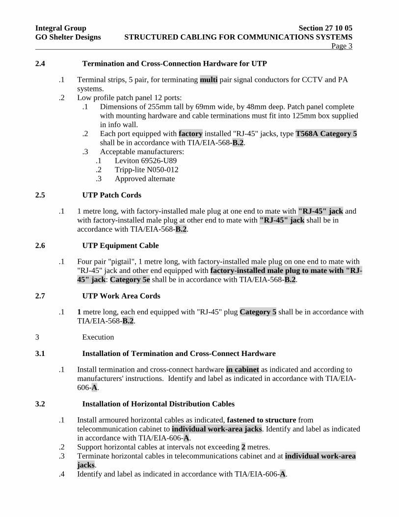
Integral Group Section 27 10 05 GO Shelter Designs STRUCTURED CABLING FOR COMMUNICATIONS SYSTEMS Page 3
2.4 Termination and Cross-Connection Hardware for UTP
.1 Terminal strips, 5 pair, for terminating multi pair signal conductors for CCTV and PA systems.
.2 Low profile patch panel 12 ports: .1 Dimensions of 255mm tall by 69mm wide, by 48mm deep. Patch panel complete
with mounting hardware and cable terminations must fit into 125mm box supplied in info wall.
.2 Each port equipped with factory installed "RJ-45" jacks, type T568A Category 5 shall be in accordance with TIA/EIA-568-B.2.
.3 Acceptable manufacturers: .1 Leviton 69526-U89 .2 Tripp-lite N050-012 .3 Approved alternate
2.5 UTP Patch Cords
.1 1 metre long, with factory-installed male plug at one end to mate with "RJ-45" jack and with factory-installed male plug at other end to mate with "RJ-45" jack shall be in accordance with TIA/EIA-568-B.2.
2.6 UTP Equipment Cable
.1 Four pair "pigtail", 1 metre long, with factory-installed male plug on one end to mate with "RJ-45" jack and other end equipped with factory-installed male plug to mate with "RJ-45" jack: Category 5e shall be in accordance with TIA/EIA-568-B.2.
2.7 UTP Work Area Cords
.1 1 metre long, each end equipped with "RJ-45" plug Category 5 shall be in accordance with TIA/EIA-568-B.2.
3 Execution
3.1 Installation of Termination and Cross-Connect Hardware
.1 Install termination and cross-connect hardware in cabinet as indicated and according to manufacturers' instructions. Identify and label as indicated in accordance with TIA/EIA-606-A.
3.2 Installation of Horizontal Distribution Cables
.1 Install armoured horizontal cables as indicated, fastened to structure from telecommunication cabinet to individual work-area jacks. Identify and label as indicated in accordance with TIA/EIA-606-A.
.2 Support horizontal cables at intervals not exceeding 2 metres.
.3 Terminate horizontal cables in telecommunications cabinet and at individual work-area jacks.
.4 Identify and label as indicated in accordance with TIA/EIA-606-A.
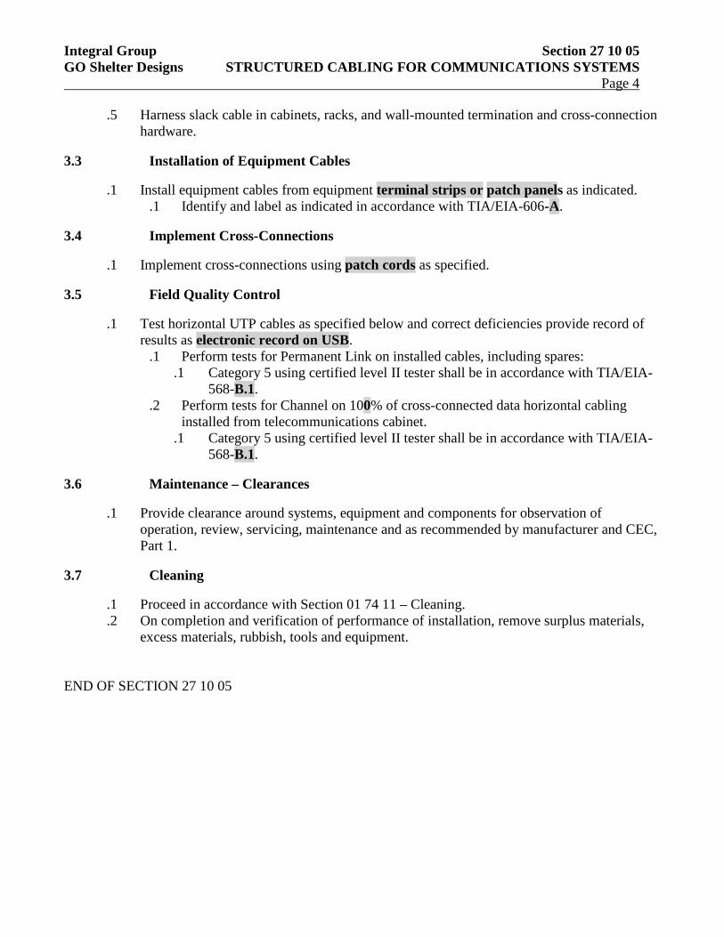
Integral Group Section 27 10 05 GO Shelter Designs STRUCTURED CABLING FOR COMMUNICATIONS SYSTEMS Page 4
.5 Harness slack cable in cabinets, racks, and wall-mounted termination and cross-connection hardware.
3.3 Installation of Equipment Cables
.1 Install equipment cables from equipment terminal strips or patch panels as indicated. .1 Identify and label as indicated in accordance with TIA/EIA-606-A.
3.4 Implement Cross-Connections
.1 Implement cross-connections using patch cords as specified.
3.5 Field Quality Control
.1 Test horizontal UTP cables as specified below and correct deficiencies provide record of results as electronic record on USB.
.1 Perform tests for Permanent Link on installed cables, including spares: .1 Category 5 using certified level II tester shall be in accordance with TIA/EIA-
568-B.1. .2 Perform tests for Channel on 100% of cross-connected data horizontal cabling
installed from telecommunications cabinet. .1 Category 5 using certified level II tester shall be in accordance with TIA/EIA-
568-B.1.
3.6 Maintenance – Clearances
.1 Provide clearance around systems, equipment and components for observation of operation, review, servicing, maintenance and as recommended by manufacturer and CEC, Part 1.
3.7 Cleaning
.1 Proceed in accordance with Section 01 74 11 – Cleaning.
.2 On completion and verification of performance of installation, remove surplus materials, excess materials, rubbish, tools and equipment.
END OF SECTION 27 10 05
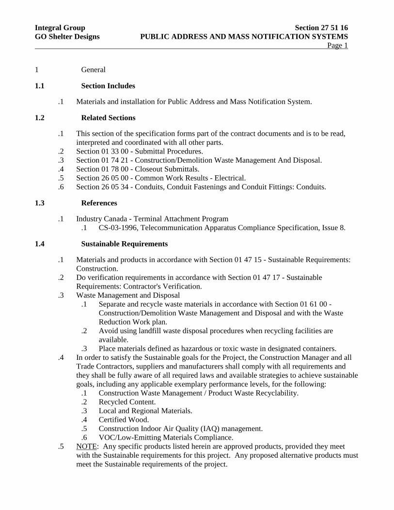
Integral Group Section 27 51 16 GO Shelter Designs PUBLIC ADDRESS AND MASS NOTIFICATION SYSTEMS Page 1
1 General
1.1 Section Includes
.1 Materials and installation for Public Address and Mass Notification System.
1.2 Related Sections
.1 This section of the specification forms part of the contract documents and is to be read, interpreted and coordinated with all other parts.
.2 Section 01 33 00 - Submittal Procedures.
.3 Section 01 74 21 - Construction/Demolition Waste Management And Disposal.
.4 Section 01 78 00 - Closeout Submittals.
.5 Section 26 05 00 - Common Work Results - Electrical.
.6 Section 26 05 34 - Conduits, Conduit Fastenings and Conduit Fittings: Conduits.
1.3 References
.1 Industry Canada - Terminal Attachment Program .1 CS-03-1996, Telecommunication Apparatus Compliance Specification, Issue 8.
1.4 Sustainable Requirements
.1 Materials and products in accordance with Section 01 47 15 - Sustainable Requirements: Construction.
.2 Do verification requirements in accordance with Section 01 47 17 - Sustainable Requirements: Contractor's Verification.
.3 Waste Management and Disposal .1 Separate and recycle waste materials in accordance with Section 01 61 00 -
Construction/Demolition Waste Management and Disposal and with the Waste Reduction Work plan.
.2 Avoid using landfill waste disposal procedures when recycling facilities are available.
.3 Place materials defined as hazardous or toxic waste in designated containers. .4 In order to satisfy the Sustainable goals for the Project, the Construction Manager and all
Trade Contractors, suppliers and manufacturers shall comply with all requirements and they shall be fully aware of all required laws and available strategies to achieve sustainable goals, including any applicable exemplary performance levels, for the following:
.1 Construction Waste Management / Product Waste Recyclability.
.2 Recycled Content.
.3 Local and Regional Materials.
.4 Certified Wood.
.5 Construction Indoor Air Quality (IAQ) management.
.6 VOC/Low-Emitting Materials Compliance. .5 NOTE: Any specific products listed herein are approved products, provided they meet
with the Sustainable requirements for this project. Any proposed alternative products must meet the Sustainable requirements of the project.
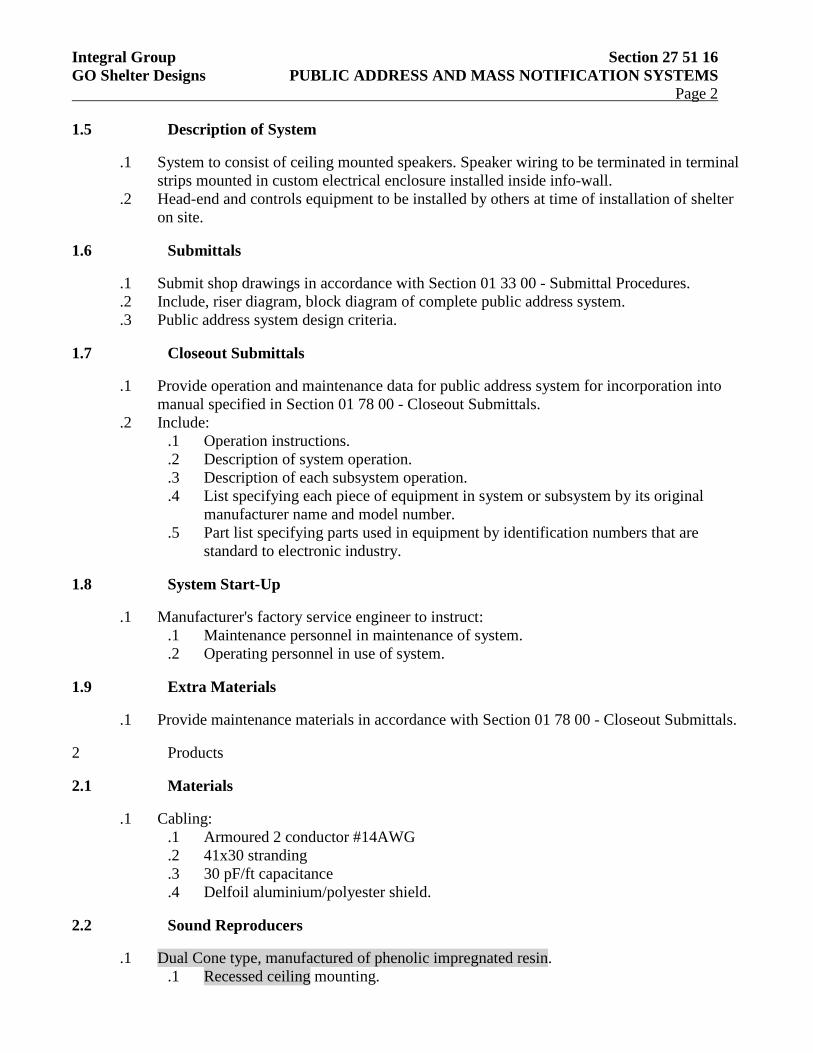
Integral Group Section 27 51 16 GO Shelter Designs PUBLIC ADDRESS AND MASS NOTIFICATION SYSTEMS Page 2
1.5 Description of System
.1 System to consist of ceiling mounted speakers. Speaker wiring to be terminated in terminal strips mounted in custom electrical enclosure installed inside info-wall.
.2 Head-end and controls equipment to be installed by others at time of installation of shelter on site.
1.6 Submittals
.1 Submit shop drawings in accordance with Section 01 33 00 - Submittal Procedures.
.2 Include, riser diagram, block diagram of complete public address system.
.3 Public address system design criteria.
1.7 Closeout Submittals
.1 Provide operation and maintenance data for public address system for incorporation into manual specified in Section 01 78 00 - Closeout Submittals.
.2 Include: .1 Operation instructions. .2 Description of system operation. .3 Description of each subsystem operation. .4 List specifying each piece of equipment in system or subsystem by its original
manufacturer name and model number. .5 Part list specifying parts used in equipment by identification numbers that are
standard to electronic industry.
1.8 System Start-Up
.1 Manufacturer's factory service engineer to instruct: .1 Maintenance personnel in maintenance of system. .2 Operating personnel in use of system.
1.9 Extra Materials
.1 Provide maintenance materials in accordance with Section 01 78 00 - Closeout Submittals.
2 Products
2.1 Materials
.1 Cabling: .1 Armoured 2 conductor #14AWG .2 41x30 stranding .3 30 pF/ft capacitance .4 Delfoil aluminium/polyester shield.
2.2 Sound Reproducers
.1 Dual Cone type, manufactured of phenolic impregnated resin. .1 Recessed ceiling mounting.
Integral Group Section 27 51 16 GO Shelter Designs PUBLIC ADDRESS AND MASS NOTIFICATION SYSTEMS Page 3
.2 Finish colour: white.
.3 Outdoor vandal resistant die-cast enclosure.
.4 Acoustic treatment: sealed speakers with a sealed back for extra protection and audibility.
.5 Faceplate and back box.
.6 Line transformer: 70 V primary with tapped secondary for volume adjustment.
.7 Power input to driver: 8 W continuous.
.8 Operating temperature range of -30oC to 50oC
3 Execution
3.1 Installation
.1 Install equipment in accordance with manufacturer's instructions, and as indicated.
3.2 Field Quality Control
.1 Perform tests in accordance with Section 26 05 00 - Common Work Results - Electrical.
.2 Conduct intelligibility test.
3.3 Maintenance – Clearances
.1 Provide clearance around systems, equipment and components for observation of operation, review, servicing, maintenance and as recommended by manufacturer and CEC, Part 1.
3.4 Cleaning
.1 Proceed in accordance with Section 01 74 11 – Cleaning.
.2 On completion and verification of performance of installation, remove surplus materials, excess materials, rubbish, tools and equipment.
END OF SECTION 27 51 16
Integral Group Section 27 51 23 GO Shelter Designs INTERCOMMUNICATION AND PROGRAM SYSTEMS Page 1
1 General
1.1 Section Includes
.1 Materials and installation for Intercommunications and Program Systems.
1.2 Related Sections
.1 This section of the specification forms part of the contract documents and is to be read, interpreted and coordinated with all other parts.
.2 Section 01 33 00 - Submittal Procedures.
.3 Section 01 74 21 - Construction/Demolition Waste Management And Disposal.
.4 Section 01 78 00 - Closeout Submittals.
.5 Section 26 05 00 - Common Work Results - Electrical.
1.3 References
.1 Canadian Standards Association (CSA International) .1 CSA C22.1 (current edition), Canadian Electrical Code, Part 1
1.4 Sustainable Requirements
.1 Materials and products in accordance with Section 01 47 15 - Sustainable Requirements: Construction.
.2 Do verification requirements in accordance with Section 01 47 17 - Sustainable Requirements: Contractor's Verification.
.3 Waste Management and Disposal .1 Separate and recycle waste materials in accordance with Section 01 61 00 -
Construction/Demolition Waste Management and Disposal and with the Waste Reduction Work plan.
.2 Avoid using landfill waste disposal procedures when recycling facilities are available.
.3 Place materials defined as hazardous or toxic waste in designated containers. .4 In order to satisfy the Sustainable goals for the Project, the Construction Manager and all
Trade Contractors, suppliers and manufacturers shall comply with all requirements and they shall be fully aware of all required laws and available strategies to achieve sustainable goals, including any applicable exemplary performance levels, for the following:
.1 Construction Waste Management / Product Waste Recyclability.
.2 Recycled Content.
.3 Local and Regional Materials.
.4 Certified Wood.
.5 Construction Indoor Air Quality (IAQ) management.
.6 VOC/Low-Emitting Materials Compliance. .5 NOTE: Any specific products listed herein are approved products, provided they meet
with the Sustainable requirements for this project. Any proposed alternative products must meet the Sustainable requirements of the project.
1.5 Submittals
Integral Group Section 27 51 23 GO Shelter Designs INTERCOMMUNICATION AND PROGRAM SYSTEMS Page 2
.1 Submit product data in accordance with Section 01 33 00 - Submittal Procedures.
1.6 Closeout Submittals
.1 Provide data for incorporation into maintenance manual specified in Sections 01 78 00 - Closeout Submittals.
.2 Include description of system operation.
.3 Include parts list using component identification numbers standard to electronics industry.
1.7 Extra Materials
.1 Provide maintenance materials in accordance with Section 01 78 00 - Closeout Submittals.
2 Products
2.1 Materials
.1 Cabling: .1 Armoured Cat 5 cabling for communication wiring, in accordance with Section 27
10 05 Structured Cabling for Communication Systems. .2 Armoured two conductor #14AWG cabling for power supply connections, in
accordance with Section 26 05 21.02 Wires and Cables (0-600V).
2.2 Substations
.1 Wall Outdoor type. .1 Full duplex capable, vandal resistant station connected directly to the GO Ethernet
Network using SIP protocol. .2 Back-lit emergency call button .3 Omni-directional electret microphone with 7 meter speaking distance. .4 Membrane type loudspeaker; 2 x 8 ohm .5 Built-in 2.5W class D amplifier. .6 IP-65 stainless steel housing. .7 Operating temperature range: -20oC to 60oC
2.3 Power Supply
.1 Power supply unit, for selector switch type system, well filtered, regulated, constant voltage under load.
.1 Output: 24 V DC at 500 mA.
.2 Input: 110-120 V, 60 Hz.
.3 Power consumption: 2 W.
.4 Rectifier: silicon full wave bridge.
.5 Filter, choke and dual capacitors.
.6 Hook-up, (+) (-) terminal strip with terminal screws.
.7 Line cord: 2 m, three conductor with specially constructed strain relief.
.8 Housing: metal case.
3 Execution
Integral Group Section 27 51 23 GO Shelter Designs INTERCOMMUNICATION AND PROGRAM SYSTEMS Page 3
3.1 Installation
.1 Install equipment as indicated and in accordance with manufacturer's instructions.
.2 Interconnect system components.
.3 Terminate power and communication wiring in terminal blocks and patch panel provided in custom electrical enclosures mounted in info-wall.
3.2 Tests
.1 Perform tests in accordance with Section 26 05 00 - Common Work Results - Electrical.
3.3 Maintenance – Clearances
.1 Provide clearance around systems, equipment and components for observation of operation, review, servicing, maintenance and as recommended by manufacturer and CEC, Part 1.
3.4 Cleaning
.1 Proceed in accordance with Section 01 74 11 – Cleaning.
.2 On completion and verification of performance of installation, remove surplus materials, excess materials, rubbish, tools and equipment.

SPECIFICATION
of
ELECTRONIC SAFETY AND SECURITY WORK
for
GO Shelter Designs
Ontario
for
Metrolinx
ELECTRICAL CONSULTANT Integral Group 2nd Flr, 1214 – 9th Avenue SE Calgary, AB T2G 0T1
PROJECT NO: 210007.000
ISSUED FOR 100% DETAILED DESIGN
ISSUE DATE: 2016-07-26

Integral Group Section 28 00 00 GO Shelter Designs TABLE OF CONTENTS Page 1
Section No. Description 28 23 00 Video Surveillance
Integral Group Section 28 23 00 GO Shelter Designs VIDEO SURVEILLANCE Page 1
1 General
1.1 Section Includes
.1 Materials and installation for Video Surveillance.
1.2 Related Requirements
.1 This section of the specification forms part of the contract documents and is to be read, interpreted and coordinated with all other parts.
1.3 References
.1 Underwriters Laboratories of Canada (ULC): .1 ULC-S317-1996, Installation and Classification of Closed Circuit Video Equipment
(CCVC) Systems for Institutional and Commercial Security Systems.
1.4 Sustainable Requirements
.1 Materials and products in accordance with Section 01 47 15 - Sustainable Requirements: Construction.
.2 Do verification requirements in accordance with Section 01 47 17 - Sustainable Requirements: Contractor's Verification.
.3 Waste Management and Disposal .1 Separate and recycle waste materials in accordance with Section 01 61 00 -
Construction/Demolition Waste Management and Disposal and with the Waste Reduction Work plan.
.2 Avoid using landfill waste disposal procedures when recycling facilities are available.
.3 Place materials defined as hazardous or toxic waste in designated containers. .4 In order to satisfy the Sustainable goals for the Project, the Construction Manager and all
Trade Contractors, suppliers and manufacturers shall comply with all requirements and they shall be fully aware of all required laws and available strategies to achieve sustainable goals, including any applicable exemplary performance levels, for the following:
.1 Construction Waste Management / Product Waste Recyclability.
.2 Recycled Content.
.3 Local and Regional Materials.
.4 Certified Wood.
.5 Construction Indoor Air Quality (IAQ) management.
.6 VOC/Low-Emitting Materials Compliance. .5 NOTE: Any specific products listed herein are approved products, provided they meet
with the Sustainable requirements for this project. Any proposed alternative products must meet the Sustainable requirements of the project.
1.5 Submittals
.1 Submit in accordance with Section 01 33 00 - Submittal Procedures.
.2 Product Data:
Integral Group Section 28 23 00 GO Shelter Designs VIDEO SURVEILLANCE Page 2
.1 Submit manufacturer's instructions, printed product literature and data sheets for video surveillance equipment and include product characteristics, performance criteria, physical size, finish and limitations.
.2 Submit: .1 Functional description of equipment. .2 Technical data sheets of all devices. .3 Device location plans and cable lists. .4 Video camera surveillance chart. .5 Video interconnection detail drawings.
.3 Shop Drawings: .1 Submit shop drawings to indicate project layout, camera locations, point-to-point
diagrams, cable schematics, risers, mounting details and identification labeling scheme.
.2 Submit zone layout drawings indicating number and location of zones and areas covered.
.4 Certificates: Submit certificates signed by manufacturer certifying that materials comply with specified performance characteristics and physical properties.
.1 Submit UL Product safety Certificates. .5 Test and Evaluation Reports:
.1 Submit certified test reports from approved independent testing laboratories indicating compliance with specifications for specified performance characteristics and physical properties.
.6 Manufacturer's Instructions: Submit manufacturer's installation instructions.
.7 Manufacturer's Field Reports: Submit manufacturer's written reports within three days of review, verifying compliance of Work, as described in Item 3 - Field Quality Control.
1.6 Closeout Submittals
.1 Operation and Maintenance Data: Submit maintenance data for incorporation into manual specified in Section 01 78 00 - Closeout Submittals. Include the following:
.1 System configuration and equipment physical layout.
.2 Functional description of equipment.
.3 Manufacturer's Instructions for operation, adjustment and cleaning.
.4 Illustrations and diagrams to supplement procedures.
1.7 Delivery, Storage and Handling
.1 Deliver, store and handle materials in accordance with Section 01 61 00 - Common Product Requirements and with manufacturer's written instructions.
.2 Delivery and Acceptance Requirements: Deliver materials to site in original factory packaging, labelled with manufacturer's name and address.
.3 Storage and Handling Requirements: .1 Store materials in accordance with manufacturer's recommendations in clean, dry,
well-ventilated area. .2 Store and protect video surveillance materials from nicks, scratches, and blemishes. .3 Replace defective or damaged materials with new.
1.8 Warranty
Integral Group Section 28 23 00 GO Shelter Designs VIDEO SURVEILLANCE Page 3
.1 Extended warranty period must include warranty against defects in construction or manufacturing meeting specified performance requirements, for specified time period.
.2 Manufacturer's Warranty: Submit, for Engineer acceptance, manufacturer's standard warranty document executed by authorized company official.
2 Products
2.1 Design Criteria
.1 Support: Camera functions such as pan/tilt and zoom fully supported by Closed Circuit Television (CCTV) system.
.1 Provide operator with ability to control all camera functions. .2 New CCTV cameras to be fed from network switch provided by others. Camera controls to
be integrated with existing GO CCTV network .3 Environment: Design video components and systems to operate with specified
requirements under following ambient temperatures: .1 Indoor Installations:
.1 Temperature: 0°C to 30°C.
.2 Humidity: 10 to 90%. .2 Outdoor Installations:
.1 Temperature: -40°C to 60°C.
.2 Humidity: 10 to 100%.
2.2 Characteristics
.1 Pan-Tilt-Zoom Video Camera: .1 Colour. .2 Resolution: Lines of horizontal resolution:
.1 Colour: Standard 320-350. .3 Format: 1/4". .4 Environment: Outdoor. .5 Mounting: Visible. .6 Lens Functions: Variable focus length 3.5 to 98mm. .7 Additional Features: Backlight compensation. .8 Operational Voltage: Standard 24 AC, 12 DC. .9 Current Consumption: 60 Watts. .10 Operation Temperature: -40oC to 50oC.
.2 Lenses: .1 Motorized Zoom Lens.
2.3 Camera Housings
.1 Domes: Outdoor.
.2 Outdoor: Equipped with heater/blower.
.3 Transmission Methods: Cat5 Ethernet.
2.4 Camera Power Supply
Integral Group Section 28 23 00 GO Shelter Designs VIDEO SURVEILLANCE Page 4
.1 Power supply shall be custom designed for all cameras requiring 24 VAC power, locate inside equipment cabinet; fused (each input and output); capable of providing correct voltage to overcome real and circulated system power loss for 2 cameras. Permanently mount power supply.
2.5 Junction Box
.1 Metal, sized to handle all system conduit interconnections with appropriate expansion.
3 Execution
3.1 Examination
.1 Verification of Conditions: Verify conditions of substrates previously installed under other Sections or Contracts are acceptable for video surveillance installation in accordance with manufacturer's written instructions.
3.2 Installation
.1 Comply with manufacturer's written data, including product technical bulletins, product catalogue installation instructions, product carton installation instructions, and data sheet.
.2 Install video surveillance equipment and components in accordance with ULC-S317.
.3 Install cable, boxes, mounting hardware, brackets, video cameras and system components in accordance with manufacturer's written installation instructions.
.4 Install components secure, properly aligned and in locations shown on reviewed shop drawings.
.5 Connect cameras to cabling in accordance with installation instructions.
.6 Install ULC labels where required.
3.3 Field Quality Control
.1 Manufacturer's Field Services: .1 Obtain written reports from manufacturer verifying compliance of Work, in
handling, installing, applying, protecting and cleaning of product. .2 Submit manufacturer's field services consisting of product use recommendations
and periodic site visits for inspection of product installation in accordance with manufacturer's instructions.
3.4 System Start-Up
.1 Perform verification inspections and test in the presence of Engineer. .1 Provide all necessary tools, ladders and equipment. .2 Ensure appropriate subcontractors, and manufacturer's representatives are present
for verification. .2 Visual Verification: Objective is to assess quality of installation and assembly and overall
appearance to ensure compliance with Contract Documents. Visual inspection to include: .1 Sturdiness of equipment fastening. .2 Non-existence of installation related damages. .3 Compliance of device locations with reviewed shop drawings.
Integral Group Section 28 23 00 GO Shelter Designs VIDEO SURVEILLANCE Page 5
.4 Compatibility of equipment installation with physical environment.
.5 Inclusion of all accessories.
.6 Device and cabling identification.
.7 Application and location of ULC approval decals. .3 Technical Verification: Purpose to ensure that all systems and devices are properly
installed and free of defects and damage. Technical verification includes: .1 Measurements of tension and power. .2 Connecting joints and equipment fastening. .3 Measurements of signals (dB, lux, baud rate, etc). .4 Compliance with manufacturer's specification, product literature and installation
instructions. .4 Operational Verification: Purpose to ensure that devices and systems' performance meet or
exceed established functional requirements. Operational verification includes: .1 Operation of each device individually and within its environment. .2 Operation of each device in relation with programmable schedule and or/specific
functions. .3 Operation control of camera lens, pan, tilt and zoom. .4 Switching of camera to any monitor. .5 Switching of system video recorder to selective monitor. .6 Set dwell times. .7 Demonstrate:
.1 Sequence viewing of cameras on each monitor.
.2 Bypass capability.
.3 Display of stored image to cardholder.
3.5 Adjusting
.1 Remove protective coverings from cameras and components.
.2 Adjust cameras for correct function.
3.6 Cleaning
.1 Progress Cleaning: Clean in accordance with Section 01 74 11 - Cleaning. .1 Leave Work area clean at end of each day.
.2 Final Cleaning: Upon completion remove surplus materials, rubbish, tools and equipment in accordance with Section 01 74 11 - Cleaning.
.1 Clean camera housing, system components and lens, free from marks, packing tape, and finger prints, in accordance with manufacturer's written cleaning recommendations.
3.7 Protection
.1 Protect installed products and components from damage during construction.
.2 Repair damage to adjacent materials caused by video surveillance installation.
3.8 Maintenance – Clearances

Integral Group Section 28 23 00 GO Shelter Designs VIDEO SURVEILLANCE Page 6
.1 Provide clearance around systems, equipment and components for observation of operation, review, servicing, maintenance and as recommended by manufacturer and CEC, Part 1.
END OF SECTION 28 23 00
Related Documents