Technical Data Original Instructions Kinetix Rotary and Linear Motion Cable Specifications Kinetix 2090 This document provides catalog numbers, product specifications, and dimensions for motor cables. Use this publication along with the Kinetix® Motion Control Selection Guide, publication KNX-SG001 , and the drive-system design guides to help make decisions on the motion control products that are best suited for your system requirements. See Additional Resources on page 77 for publication numbers. Topic Page Summary of Changes 2 Kinetix Motor Single Cables 3 Kinetix Motor Power and Feedback Cables 20 Kinetix TL and TLY Motor Power and Feedback Cables 57 Kinetix TLP Motor Power and Feedback Cables 62

Welcome message from author
This document is posted to help you gain knowledge. Please leave a comment to let me know what you think about it! Share it to your friends and learn new things together.
Transcript

Technical DataOriginal Instructions
Kinetix Rotary and Linear Motion Cable SpecificationsKinetix 2090
This document provides catalog numbers, product specifications, and dimensions for motor cables.
Use this publication along with the Kinetix® Motion Control Selection Guide, publication KNX-SG001, and the drive-system design guides to help make decisions on the motion control products that are best suited for your system requirements. See Additional Resources on page 77 for publication numbers.
Topic PageSummary of Changes 2Kinetix Motor Single Cables 3Kinetix Motor Power and Feedback Cables 20Kinetix TL and TLY Motor Power and Feedback Cables 57Kinetix TLP Motor Power and Feedback Cables 62
Kinetix Rotary and Linear Motion Cable Specifications Technical Data
Summary of ChangesThis publication contains the following new or updated information. This list includes substantive updates only and is not intended to reflect all changes.
Topic PageAdded Kinetix MMA main motors to the Motor Connector/Cable Plug Compatibility table. 27Added Kinetix MMA main motors to the Kinetix Motor Power and Feedback Cable Selection section. 35Added a section for Kinetix TL and TLY Motor Power and Feedback Cables 57This is the first revision as publication KNX-TD004 with information for Kinetix 5700, 5500, 5300, and 5100 Servo Drives.Publication KNX-TD005 has information for Kinetix 3, 300, 350, 2000, 6000, 6200, 6500, 7000 Servo Drives. —
2 Rockwell Automation Publication KNX-TD004J-EN-P - October 2021

Kinetix Motor Single Cables
Kinetix Motor Single CablesKinetix 2090 single motor cables combine motor power, feedback, and brake conductors all in a single shielded cable. Standard (non-flex) motor cables with rugged SpeedTec DIN connectors are designed for use with Kinetix 5500 and Kinetix 5700 drive systems, and intended for static applications. Continuous-flex rated cables, intended for rolling and reverse bending applications, are also available.
These Kinetix 2090 motor cables with SpeedTec DIN connectors, designed by Rockwell Automation for optimal performance with Kinetix 5500 and Kinetix 5700 drive families with Kinetix VP motors and actuators, offer best-in-class features and standards compliance. The single-cable design includes power, feedback, and brake conductors. The continuous-flex cable option, cable lengths in 1 m (3.3 ft) increments, and SpeedTec connectors provide machine builders with complete control of the cable requirements in their machines.
Single Motor Cable Features
Single motor cables are available in three cable materials:• TPE for standard (non-flex) and continuous-flex cable• PVC for standard (non-flex) and Halogen-free PUR for continuous-flex cable
Common Single Motor-cable Features• NFPA-79 compliant• Low capacitance design to maximize system power density• SpeedTec connection system• Encoder communication data pair with state of the art noise rejection• DESINA compliant jacket (orange) coloring for easy identification and separation of cables in a machine• Cables are included in the Rockwell Automation® servo system Declaration of Conformity (DoC)
IMPORTANT Because of the unique characteristics of single-cable technology, which is designed for and tested with the Kinetix 5500 and Kinetix 5700 drive families with Kinetix VP motors and actuators, building your own cables, using field modified Rockwell Automation® factory-delivered cable, or using third-party cable is not an option.
IMPORTANT Flying-lead motor power, feedback, and (optional) brake conductors terminate at the drive by using the 2198-KITCON-DSL feedback connector kit. Refer to the Kinetix 5700, 5500, 5300, 5100 Servo Drives Specifications Technical Data, publication KNX-TD003, for more information on the 2198-KITCON-DSL connector kit that is used with the Kinetix 5500 and Kinetix 5700 servo drives.
IMPORTANT Continuous-flex single motor cables have a minimum bend radius of 10 times the cable diameter for 2090-CSxM1xx-xxAFxx (TPE) cables and 7 times the cable diameter for 2090-CSBM1xx-xxLFxx (Halogen-free PUR) cables.
Rockwell Automation Publication KNX-TD004J-EN-P - October 2021 3
Kinetix Motor Single Cables
2090-CSxM1xx-xxAA/AFxx (TPE) Cable Features• UL Listings: 10, 8, and 6 AWG bulk cable - Flexible VFD servo cable, 18 and 14 AWG bulk cable - PLTC-ER
- UL AWM, 1000V, 105 °C construction- cUR AWM I/II A/B, 600V, 105 °C construction for 6 and 8 AWG cables
• CSA AWM I/II A/B, 1000V, 105 °C construction for 10, 14, and 18 AWG cables• Rated flex-cycles in linear flexing applications
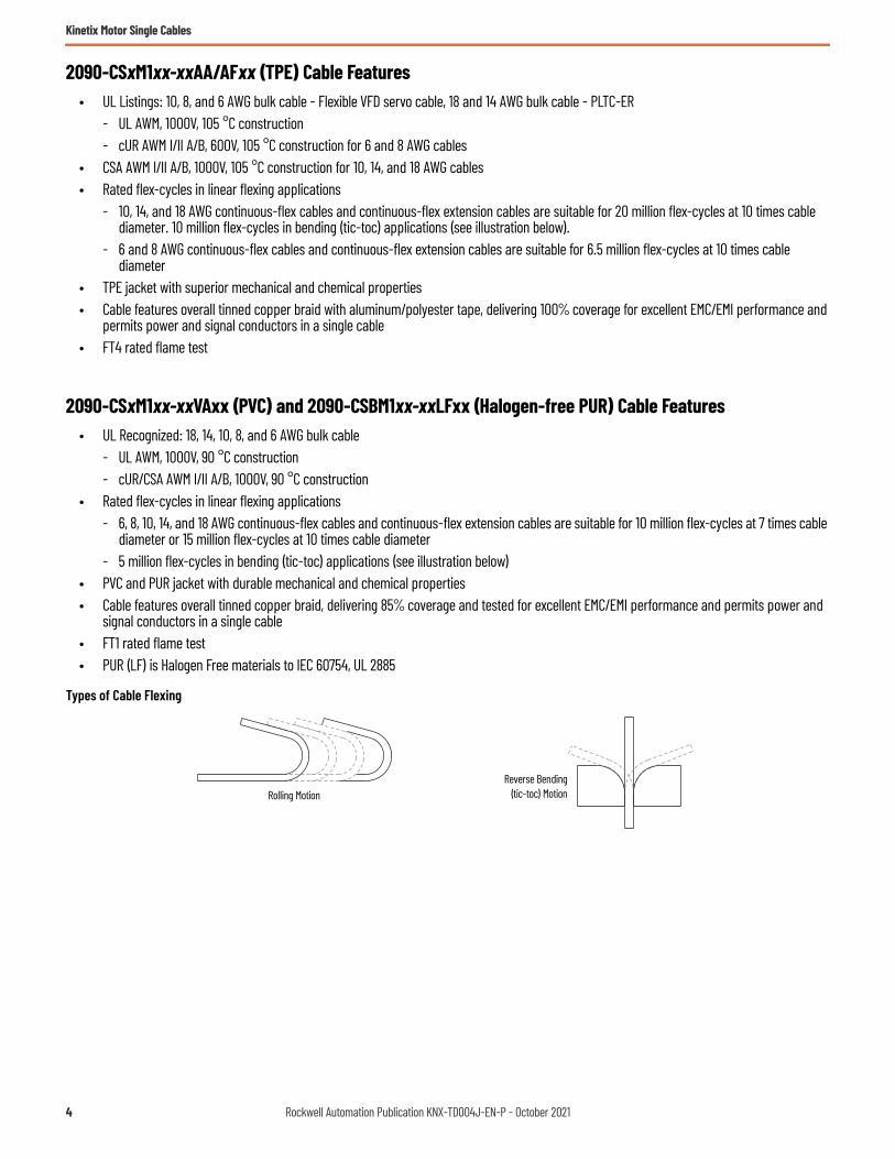
- 10, 14, and 18 AWG continuous-flex cables and continuous-flex extension cables are suitable for 20 million flex-cycles at 10 times cable diameter. 10 million flex-cycles in bending (tic-toc) applications (see illustration below).
- 6 and 8 AWG continuous-flex cables and continuous-flex extension cables are suitable for 6.5 million flex-cycles at 10 times cable diameter
• TPE jacket with superior mechanical and chemical properties• Cable features overall tinned copper braid with aluminum/polyester tape, delivering 100% coverage for excellent EMC/EMI performance and
permits power and signal conductors in a single cable• FT4 rated flame test
2090-CSxM1xx-xxVAxx (PVC) and 2090-CSBM1xx-xxLFxx (Halogen-free PUR) Cable Features• UL Recognized: 18, 14, 10, 8, and 6 AWG bulk cable
- UL AWM, 1000V, 90 °C construction- cUR/CSA AWM I/II A/B, 1000V, 90 °C construction
• Rated flex-cycles in linear flexing applications- 6, 8, 10, 14, and 18 AWG continuous-flex cables and continuous-flex extension cables are suitable for 10 million flex-cycles at 7 times cable
diameter or 15 million flex-cycles at 10 times cable diameter - 5 million flex-cycles in bending (tic-toc) applications (see illustration below)
• PVC and PUR jacket with durable mechanical and chemical properties• Cable features overall tinned copper braid, delivering 85% coverage and tested for excellent EMC/EMI performance and permits power and
signal conductors in a single cable• FT1 rated flame test• PUR (LF) is Halogen Free materials to IEC 60754, UL 2885
Types of Cable Flexing
Rolling MotionReverse Bending
(tic-toc) Motion
4 Rockwell Automation Publication KNX-TD004J-EN-P - October 2021

Kinetix Motor Single Cables
Catalog Numbers - Kinetix Single Motor Cables
Catalog numbers consist of various characters, each of which identifies a specific option for that component. Use the catalog numbering charts below to understand the configuration of your component. For questions regarding product availability, contact your Allen-Bradley distributor.
Kinetix Single Motor Cables Overview
2090-CSxM1DF and 2090-CSxM1DG single motor cables with flying leads provide power, feedback, and brake conductors in a single shielded cable. Refer to Technical Specifications - Kinetix 2090 Single Motor Cables on page 12 for cable descriptions, weights, and standard cable lengths.
Single Motor Cable Descriptions (flying leads)
2090-CSxM1DE single motor cables also provide power, feedback, and brake conductors in a single shielded cable. However, 2090-CSxM1DE cables include the 2198-KITCON-DSL feedback connector kit that is pre-assembled with the feedback conductors. See Technical Specifications - Kinetix 2090 Single Motor Cables on page 12 for cable descriptions, weights, and standard cable lengths.
Cable Cat. No. DescriptionCable Configuration
Motor ConnectorMotor End Drive End
2090-CSBM1DF-xxAAxx2090-CSBM1DF-xxAFxx2090-CSBM1DG-xxxAxx2090-CSBM1DG-xxxFxx
• Drive-end flying-leads (DF) (DG = longer lead lengths)• Power/feedback/brake wires (SB)• Standard, non-flex (AA, VA)• Continuous-flex (AF, LF) SpeedTec DIN
2090-CSWM1DF-xxAAxx2090-CSWM1DG-xxxAxx
• Drive-end flying-leads (DF) (DG = longer lead lengths)• Power/feedback wires only (SW)• Standard, non-flex (AA, VA)
2090 - C Sx M1 Dx - xx xx xxCable LengthRefer to Technical Specifications - Kinetix 2090 Single Motor Cables beginning on page 12.
Wire Gauge Size (applies to power conductors)18, 14, 10, 8, 6 AWG
Cable TypeSB = Single motor power with brake wiresSW = Single motor power only
Cable Material TypeAA = TPE, Standard, non-flexAF = TPE, Continuous-flexLF = PUR, Continuous-flex, Halogen freeVA = PVC, Standard, non-flex
Accessory ComponentC = CableBulletin Number
Motor-end Connector TypeM1 = Single SpeedTec DIN connector
Drive-end Connector TypeDF = Drive-end, flying-leads (lead length optimized for Kinetix 5500 drives)DE = Drive-end, flying-lead power/brake wires and pre-wired feedback connector kit (optimized for Kinetix 5700 drives)DG = Drive-end, flying-leads (longer leads optimized for Kinetix 5500 or Kinetix 5700 drives)E1 = Extension receptacle (SpeedTec ready)
Rockwell Automation Publication KNX-TD004J-EN-P - October 2021 5

Kinetix Motor Single Cables
Single Motor Cable Descriptions (feedback connector kit)
Optimize the placement of your continuous-flex application with extension cables. Use standard (non-flex) extension cables to cover distances that are outside of the continuous-flex application. For example, attach a standard (non-flex) extension cable to the motor and use a continuous-flex flying lead cable for applications that require flexing closer to the drive. The stationary portion of cable can stay routed permanently throughout the application while the continuous-flex cable can be placed in the location that may need maintenance, changeovers, replacement, or general services.
The IP rating for extension cables is consistent with the motor/actuator and cable combination they are extending. Extension cables are available with 18, 14, 10, 8, and 6 AWG power conductors and lengths up to 30 m (98.4 ft).
Single Extension Cable Description
Typical Single Motor Cable Applications
Cable Cat. No. DescriptionCable Configuration
Motor ConnectorMotor End Drive End
2090-CSBM1DE-xxxAxx2090-CSBM1DE-xxxFxx
• Drive-end feedback connector kit (DE)• Power/feedback/brake wires (SB)• Standard, non-flex (AA, VA)• Continuous-flex (AF, LF)
SpeedTec DIN
2090-CSWM1DE-xxxAxx• Drive-end feedback connector kit (DE)• Power/feedback wires only (SW)• Standard, non-flex (AA, VA)
Cable Cat. No. DescriptionCable Configuration
Motor ConnectorMotor End Drive End
2090-CSBM1E1-xxxFxx2090-CSBM1E1-xxVAxx
• Drive-end (male) connector, extension (E1) (1)• Motor-end SpeedTec DIN cable plug (M1)• Standard, non-flex (VA)• Continuous-flex (AF, LF)
(1) SpeedTec DIN connector (motor end) and male connector for extending SpeedTec DIN cable. Refer to Single Continuous-flex Extension Cable with Bulkhead Adapter Example on page 7.
SpeedTec DIN
• Attach cable plug with 1/8 to 1/4 turn• Receives only single motor cable plugs
SpeedTec DIN Connector
SpeedTec DIN (M1) Single Cable Plug
• Attach cable plug with 1/8 to 1/4 turn• Receives only single motor cable plugs• 5 m (16.4 ft) cable extension
• 2090-CSBM1DF-xxAAxx (standard, non-flex) power/feedback/brake cables• 2090-CSWM1DF-xxAAxx (standard, non-flex) power/feedback cables• 2090-CSBM1DF-xxAFxx (continuous-flex) power/feedback/brake cables
• 2090-CSBM1DE-xxxAxx (standard, non-flex) power/feedback/brake cables• 2090-CSWM1DE-xxxAxx (standard, non-flex) power/feedback cables• 2090-CSBM1DE-xxxFxx (continuous-flex) power/feedback/brake cables
• 2090-CSBM1DG-xxxAxx (standard, non-flex) power/feedback/brake cables• 2090-CSWM1DG-xxxAxx (standard, non-flex) power/feedback cables• 2090-CSBM1DG-xxxFxx (continuous-flex) power/feedback/brake cables
6 Rockwell Automation Publication KNX-TD004J-EN-P - October 2021

Kinetix Motor Single Cables
The cable technology used in single cables is the same regardless of the catalog number. What is different about each cable is the lead preparation and feedback conductor terminations.
• 2090-CSxM1DF cable conductors have flying-leads and lead preparation that is designed specifically for Kinetix 5500 servo drives. No on-site lead preparation is required.
• 2090-CSxM1DE cables include the 2198-KITCON-DSL connector kit. The kit is pre-assembled with the feedback conductors and lead preparation for the flying-lead power conductors is designed specifically for Kinetix 5700 servo drives. No on-site lead preparation is required.
• 2090-CSxM1DG cable conductors have flying-leads and lead preparation that is designed for either Kinetix 5500 or Kinetix 5700 servo drives. No on-site lead preparation is required, however, 2090-CSxM1DG cable leads are longer than 2090-CSxM1DF cable leads to accommodate either drive family.
Single Continuous-flex Extension Cable with Bulkhead Adapter Example
In this example, the continuous-flex application is near the motor, however, if the continuous-flex application is closer to the drive, a standard (non-flex) extension cable can be attached to the motor.
IMPORTANT To avoid problems securing the cable in the shield clamp and routing the flying leads to the motor power, feedback, and brake connector plugs, make sure that you are using the cable that is best suited for your application.• Use 2090-CSxM1DF cables with Kinetix 5500 servo drives (2198-KITCON-DSL connector kit is included with the drive)• Use 2090-CSxM1DE cables with Kinetix 5700 servo drives (2198-KITCON-DSL connector kit is pre-wired to the feedback
conductors)• Use 2090-CSxM1DG cables with Kinetix 5500 or Kinetix 5700 servo drives (when used with Kinetix 5700 drives, the
2198-KITCON-DSL connector kit is ordered separately)
Machine with Continuous-flex Cable Application
Kinetix 5500 orKinetix 5700 Servo Drive
Kinetix VPServo Motor2090-CSBM1E1-xxxFxx
Continuous-flex Extension Cable
2090-CSxM1DF 2090-CSxM1DE or2090-CSxM1DG
Single Motor Cable
2090-KPB47-xxCFBulkhead Adapter(power/brake)
Use the Kinetix 2090 bulkhead adapters to secure your cable to the machine or cabinet.
Rockwell Automation Publication KNX-TD004J-EN-P - October 2021 7

Kinetix Motor Single Cables
Kinetix Single Motor Cable Selection
These tables provide single motor cable catalog numbers for use with Kinetix VP motors and actuators. Single motor cables include conductors for motor power, feedback, and motor brakes (if applicable). The IP rating is dependent on the use of Kinetix 2090 cables as listed in the table.
Kinetix VPL 200V-class Low Inertia Motors
Kinetix VPL 400V-class Low Inertia Motors
For cable configuration illustrations and feature descriptions, by catalog number, refer to Kinetix Single Motor Cables Overview beginning on page 5.Cable length xx is in meters, 01 (3.3)…50 (164) in 1.0 m (3.3 ft) increments for 2090-CSxM1DF and 2090-CSxM1DG cables.Refer to Technical Specifications - Kinetix 2090 Single Motor Cables on page 12.
IMPORTANT Maximum motor cable length depends on the feedback type and overall system design. The drive-system power supply, AC input-power type, and AC input voltage are among the configuration variables. For more information on maximum cable lengths see your servo drive user manual or the Kinetix 5700, 5500, 5300, 5100 Servo Drives Technical Data, publication KNX-TD003.
Motor Cat. No. Compatible (1)Drive Cat. No.
(1) For information on maximum cable lengths see the Kinetix 5500 Servo Drives User Manual, publication 2198-UM001.Not all drive/motor combinations are possible. See Additional Resources on page 77 for the drive system design guide or Motion Analyzer software for drive/motor performance specifications.
Feedback Type Cable Cat. No. (2)
(2) Use 2090-CSxM1DF or 2090-CSxM1DG cables with Kinetix 5500 (2198-Hxxx-ERSx) servo drives.
IP Rating
VPL-A0631x, VPL-A0632F, VPL-A0633x
2198-Hxxx-ERS2198-Hxxx-ERS22198-Dxxx-ERS32198-Dxxx-ERS4
Single-turn or Absolute, Multi-turn Digital Encoder• SIL 2/PLd Rated• Hiperface DSL Protocol
2090-CSBM1Dx-18xAxx or2090-CSWM1Dx-18xAxx (standard, non-flex)2090-CSBM1Dx-18xFxx (continuous-flex) • IP50, min without shaft
seal (standard)• IP66 with shaft seal (3)
(3) IP66 with optional shaft seal and the use of Rockwell Automation® factory-delivered Kinetix 2090 single cable.
VPL-A0751E, VPL-A0752x, VPL-A0753xVPL-A1001C, VPL-A1003xVPL-A1001M, VPL-A1002x 2090-CSBM1Dx-14xAxx or
2090-CSWM1Dx-14xAxx (standard, non-flex)2090-CSBM1Dx-14xFxx (continuous-flex)
VPL-A1152x, VPL-A1153xVPL-A1303x, VPL-A1304x, VPL-A1306x
Motor Cat. No. Compatible (1) Drive Cat. No.
(1) For information on maximum cable lengths see Kinetix 5700 Servo Drives User Manual, publication 2198-UM002, or Kinetix 5500 Servo Drives User Manual, publication 2198-UM001.Not all drive/motor combinations are possible. See Additional Resources on page 77 for the drive system design guide or Motion Analyzer software for drive/motor performance specifications.
Feedback Type Cable Cat. No. (2)
(2) Use 2090-CSxM1DF or 2090-CSxM1DG cables with Kinetix 5500 (2198-Hxxx-ERSx) servo drives. Use 2090-CSxM1DE or 2090-CSxM1DG cables with Kinetix 5700 (2198-xxxx-ERSx) servo drives.
IP Rating
VPL-B0631x, VPL-B0632x, VPL-B0633x
2198-Hxxx-ERS2198-Hxxx-ERS22198-Dxxx-ERS32198-Dxxx-ERS4
Single-turn or Absolute, Multi-turn Digital Encoder• SIL 2/PLd Rated• Hiperface DSL Protocol
2090-CSBM1Dx-18xAxx or2090-CSWM1Dx-18xAxx (standard, non-flex)2090-CSBM1Dx-18xFxx (continuous-flex)
• IP50, min without shaft seal (standard)
• IP66 with shaft seal (3)
(3) IP66 with optional shaft seal and the use of Rockwell Automation factory-delivered Kinetix 2090 single cable.
VPL-B0751M, VPL-B0752x, VPL-B0753xVPL-B1001M, VPL-B1002E, VPL-B1003C, VPL-B1003F
VPL-B1002M, VPL-B1003T2090-CSBM1Dx-14xAxx or2090-CSWM1Dx-14xAxx (standard, non-flex)2090-CSBM1Dx-14xFxx (continuous-flex)
VPL-B1152C, VPL-B1153E2090-CSBM1Dx-18xAxx or2090-CSWM1Dx-18xAxx (standard, non-flex)2090-CSBM1Dx-18xFxx (continuous-flex)
VPL-B1152F, VPL-B1152T,VPL-B1153F
2090-CSBM1Dx-14xAxx or2090-CSWM1Dx-14xAxx (standard, non-flex)2090-CSBM1Dx-14xFxx (continuous-flex)
VPL-B1303x, VPL-B1304x, VPL-B1306xVPL-B1651C, VPL-B1651F, VPL-B1652C, VPL-B1652F, VPL-B1653C, VPL-B1653D, VPL-B1654B
VPL-B1654D 2090-CSBM1Dx-10xFxx (continuous-flex), 2090-CSBM1Dx-10VAxx (standard, non-flex)
8 Rockwell Automation Publication KNX-TD004J-EN-P - October 2021

Kinetix Motor Single Cables
Kinetix VPC 400V-class Continuous Duty Motors
Kinetix VPF 200V-class Food Grade Motors
Kinetix VPF 400V-class Food Grade Motors
For cable configuration illustrations and feature descriptions, by catalog number, refer to Kinetix Single Motor Cables Overview beginning on page 5.Cable length xx is in meters, 01 (3.3)…50 (164) in 1.0 m (3.3 ft) increments for 2090-CSxM1DF and 2090-CSxM1DG cables, 01 (3.3)…90 (294) in 1.0 m (3.3 ft) increments for 2090-CSxM1DE cables. Refer to Technical Specifications - Kinetix 2090 Single Motor Cables on page 12.
Motor Cat. No. Drive Cat. No. (1) (2)
(1) For information on maximum cable lengths see the Kinetix 5700 Servo Drives User Manual, publication 2198-UM002.Not all drive/motor combinations are possible. See Additional Resources on page 77 for the drive system design guide or Motion Analyzer software for drive/motor performance specifications.
(2) 2198-S263-ERSx and 2198-S312-ERSx single-axis inverters do not support 2090-CSxM1Dx single cables.
Feedback Type Cable Cat. No. (3)
(3) Use 2090-CSxM1DE or 2090-CSxM1DG cables with Kinetix 5700 (2198-xxxx-ERSx) servo drives.
IP RatingVPC-B1652x-Q, VPC-B1653x-Q
2198-Dxxx-ERS32198-Sxxx-ERS32198-Dxxx-ERS42198-Sxxx-ERS4
Absolute, Multi-turn Digital Encoder• SIL 2/PLd Rated• Hiperface DSL Protocol
2090-CSBM1Dx-14xAxx or2090-CSWM1Dx-14xAxx (standard, non-flex)2090-CSBM1Dx-14xFxx (continuous-flex)
IP65 with shaft seal(standard) (4)
(4) IP65 with shaft seal (standard) and the use of Rockwell Automation factory-delivered Kinetix 2090 single cable.
VPC-B2153x-Q, VPC-B21549-Q
VPC-B1654D-Q2090-CSBM1Dx-10xFxx (continuous-flex)2090-CSBM1Dx-10VAxx (standard, non-flex)VPC-B2154A-Q
VPC-B30029-QVPC-B2154B-Q, VPC-B2154D-QVPC-B2155B-Q, VPC-B2155D-Q 2090-CSBM1DE-08xFxx (continuous-flex)
2090-CSBM1DE-08VAxx (standard, non-flex)VPC-B3002A-Q, VPC-B30039-QVPC-B30049-QVPC-B2156A-Q, VPC-B2156D-Q 2090-CSBM1DE-06xFxx (continuous-flex)
2090-CSBM1DE-06VAxx (standard, non-flex)VPC-B3003A-Q
Motor Cat. No. (200V-class) Drive Cat. No. (1)
(1) For information on maximum cable lengths see the Kinetix 5500 Servo Drives User Manual, publication 2198-UM001.Not all drive/motor combinations are possible. See Additional Resources on page 77 for the drive system design guide or Motion Analyzer software for drive/motor performance specifications.
Feedback Type Cable Cat. No. (2)
(2) Use 2090-CSxM1DF or 2090-CSxM1DG cables with Kinetix 5500 (2198-Hxxx-ERSx) servo drives.
IP RatingVPF-A0632F, VPF-A0633C, VPF-A0633F
2198-Hxxx-ERS2198-Hxxx-ERS22198-Dxxx-ERS32198-Dxxx-ERS4
Single-turn or Absolute, Multi-turn Digital Encoder• SIL 2/PLd Rated• Hiperface DSL Protocol
2090-CSBM1Dx-18xAxx or2090-CSWM1Dx-18xAxx (standard, non-flex)2090-CSBM1Dx-18xFxx (continuous-flex)
IP66/IP67 with shaft seal (standard) (3)
(3) IP66/IP67 with shaft seal (standard) and the use of Rockwell Automation factory-delivered Kinetix 2090 single cable.
VPF-A0752x, VPF-A0753xVPF-A1001C, VPF-A1003CVPF-A1001M, VPF-A1002C, VPF-A1002FVPF-A1003E, VPF-A1003F 2090-CSBM1Dx-14xAxx or
2090-CSWM1Dx-14xAxx (standard, non-flex)2090-CSBM1Dx-14xFxx (continuous-flex)
VPF-A1153CVPF-A1303B, VPF-A1303F, VPF-A1304A, VPF-A1304D
Motor Cat. No. (400V-class) Drive Cat. No. (1)
(1) For information on maximum cable lengths see Kinetix 5700 Servo Drives User Manual, publication 2198-UM002, or Kinetix 5500 Servo Drives User Manual, publication 2198-UM001.Not all drive/motor combinations are possible. See Additional Resources on page 77 for the drive system design guide or Motion Analyzer software for drive/motor performance specifications.
Feedback Type Cable Cat. No. (2)
(2) Use 2090-CSxM1DF or 2090-CSxM1DG cables with Kinetix 5500 (2198-Hxxx-ERSx) servo drives. Use 2090-CSxM1DE or 2090-CSxM1DG cables with Kinetix 5700 (2198-xxxx-ERSx) servo drives.
IP RatingVPF-B0632F, VPF-B0632TVPF-B0633M, VPF-B0633T
2198-Hxxx-ERS2198-Hxxx-ERS22198-Dxxx-ERS32198-Dxxx-ERS4
Single-turn or Absolute, Multi-turn Digital Encoder• SIL 2/PLd Rated• Hiperface DSL Protocol
2090-CSBM1Dx-18xAxx or2090-CSWM1Dx-18xAxx (standard, non-flex)2090-CSBM1Dx-18xFxx (continuous-flex)
IP66/IP67 with shaft seal (standard) (3)
(3) IP66/IP67 with shaft seal (standard) and the use of Rockwell Automation factory-delivered Kinetix 2090 single cable.
VPF-B0752E, VPF-B0752F, VPF-B0752M, VPF-B0753E, VPF-B0753F, VPF-B0753MVPF-B1001M, VPF-B1002E, VPF-B1003C, VPF-B1003FVPF-B1153EVPF-B1002M, VPF-B1003T
2090-CSBM1Dx-14xAxx or2090-CSWM1Dx-14xAxx (standard, non-flex)2090-CSBM1Dx-14xFxx (continuous-flex)
VPF-B1153FVPF-B1303C, VPF-B1303F, VPF-B1304C, VPF-B1304EVPF-B1652C
Rockwell Automation Publication KNX-TD004J-EN-P - October 2021 9

Kinetix Motor Single Cables
Kinetix VPH 200V-class Hygienic Stainless Steel Motors
Kinetix VPH 400V-class Hygienic Stainless Steel Motors
Kinetix VPS 400V-class Stainless Steel Motors
For cable configuration illustrations and feature descriptions, by catalog number, refer to Kinetix Single Motor Cables Overview beginning on page 5.Cable length xx is in meters, 01 (3.3)…50 (164) in 1.0 m (3.3 ft) increments for 2090-CSxM1DF and 2090-CSxM1DG cables, 01 (3.3)…90 (294) in 1.0 m (3.3 ft) increments for 2090-CSxM1DE cables.Refer to Technical Specifications - Kinetix 2090 Single Motor Cables on page 12.
Motor Cat. No. (200V-class) Drive Cat. No. (1)
(1) For information on maximum cable lengths see the Kinetix 5500 Servo Drives User Manual, publication 2198-UM001.Not all drive/motor combinations are possible. See Additional Resources on page 77 for the drive system design guide or Motion Analyzer software for drive/motor performance specifications.
Feedback Type Cable Cat. No. (2)
(2) Use 2090-CSxM1DF or 2090-CSxM1DG cables with Kinetix 5500 (2198-Hxxx-ERSx) servo drives.
IP Rating (3)
(3) The cable connectors are rated IP66 and IP67 and are not designed to withstand high-pressure washdown or washdown with aggressive cleaning compounds. Position connectors away from direct exposure to cleaning processes, for example, within washdown-rated conduit or junction boxes.
VPH-A0633FVPH-A0753F 2198-Hxxx-ERS
2198-Hxxx-ERS22198-Dxxx-ERS32198-Dxxx-ERS4
Single-turn or Absolute, Multi-turn Digital Encoder• SIL 2/PLd Rated• Hiperface DSL Protocol
2090-CSBM1Dx-18xAxx or2090-CSWM1Dx-18xAxx (standard, non-flex)2090-CSBM1Dx-18xFxx (continuous-flex) • IP66/IP67 with shaft
seal (standard) (4)
• IP69K with shaft seal (standard) (5)
(4) IP66/IP67 with shaft seal (standard) and the use of Rockwell Automation factory-delivered Kinetix 2090 single cable (includes on-motor cable connector).(5) IP69K for 1200 psi motor washdown with shaft seal (standard). Does not include on-motor cable connector.
VPH-A1003FVPH-A1152EVPH-A1153C
2090-CSBM1Dx-14xAxx or2090-CSWM1Dx-14xAxx (standard, non-flex)2090-CSBM1Dx-14xFxx (continuous-flex)
VPH-A1304D
Motor Cat. No. (400V-class) (1)
(1) VPH-B100xx and VPH-B1152F frame on-motor cables include 14 AWG conductors and are also compatible with 2090-CSxM1Dx-14xxxx cable.
Drive Cat. No. (2)
(2) For information on maximum cable lengths see Kinetix 5700 Servo Drives User Manual, publication 2198-UM002, or Kinetix 5500 Servo Drives User Manual, publication 2198-UM001.Not all drive/motor combinations are possible. See Additional Resources on page 77 for the drive system design guide or Motion Analyzer software for drive/motor performance specifications.
Feedback Type Cable Cat. No. (3)
(3) Use 2090-CSxM1DF or 2090-CSxM1DG cables with Kinetix 5500 (2198-Hxxx-ERSx) servo drives. Use 2090-CSxM1DE or 2090-CSxM1DG cables with Kinetix 5700 (2198-xxxx-ERSx) servo drives.
IP Rating (4)
(4) The cable connectors are rated IP66 and IP67 and are not designed to withstand high-pressure washdown or washdown with aggressive cleaning compounds. Position connectors away from direct exposure to cleaning processes, for example, within washdown-rated conduit or junction boxes.
VPH-B0632T, VPH-B0633M
2198-Hxxx-ERS2198-Hxxx-ERS22198-Dxxx-ERS32198-Dxxx-ERS4
Single-turn or Absolute, Multi-turn Digital Encoder• SIL 2/PLd Rated• Hiperface DSL Protocol
2090-CSBM1Dx-18xAxx or2090-CSWM1Dx-18xAxx (standard, non-flex)2090-CSBM1Dx-18xFxx (continuous-flex)
• IP66/IP67 with shaft seal (standard) (5)
• IP69K with shaft seal (standard) (6)
(5) IP66/IP67 with shaft seal (standard) and the use of Rockwell Automation factory-delivered Kinetix 2090 single cable (includes on-motor cable connector).(6) IP69K for 1200 psi motor washdown with shaft seal (standard). Does not include on-motor cable connector.
VPH-B0753FVPH-B1001F, VPH-B1003FVPH-B1152F VPH-B1153E 2090-CSBM1Dx-14xAxx or
2090-CSWM1Dx-14xAxx (standard, non-flex)2090-CSBM1Dx-14xFxx (continuous-flex)
VPH-B1304EVPH-B1653D
Motor Cat. No. Drive Cat. No. (1)
(1) For information on maximum cable lengths see Kinetix 5700 Servo Drives User Manual, publication 2198-UM002, or Kinetix 5500 Servo Drives User Manual, publication 2198-UM001.Not all drive/motor combinations are possible. See Additional Resources on page 77 for the drive system design guide or Motion Analyzer software for drive/motor performance specifications.
Feedback Type Cable Cat. No. (2)
(2) Use 2090-CSxM1DF or 2090-CSxM1DG cables with Kinetix 5500 (2198-Hxxx-ERSx) servo drives. Use 2090-CSxM1DE or 2090-CSxM1DG cables with Kinetix 5700 (2198-xxxx-ERSx) servo drives.
IP Rating (3)
(3) The cable connectors are rated IP66 and IP67 and are not designed to withstand high-pressure washdown or washdown with aggressive cleaning compounds. Position connectors away from direct exposure to cleaning processes, for example, within washdown-rated conduit or junction boxes.
VPS-B1304D 2198-Hxxx-ERS2198-Hxxx-ERS22198-Dxxx-ERS32198-Dxxx-ERS4
Absolute, Multi-turnDigital Encoder with Hiperface DSL Protocol
2090-CSWM1Dx-14xAxx (standard, non-flex)2090-CSBM1Dx-14xFxx (continuous-flex)
• IP66/IP67 with shaft seal and slinger (standard) (4)
• IP69K with shaft seal and slinger (standard) (5)
(4) IP66/IP67 with shaft seal and slinger (standard) and the use of Rockwell Automation factory-delivered Kinetix 2090 single cable (includes on-motor cable connector).(5) IP69K for 1200 psi motor washdown with shaft seal and slinger (standard). Does not include on-motor cable connector.
VPS-B1653D
10 Rockwell Automation Publication KNX-TD004J-EN-P - October 2021
Kinetix Motor Single Cables
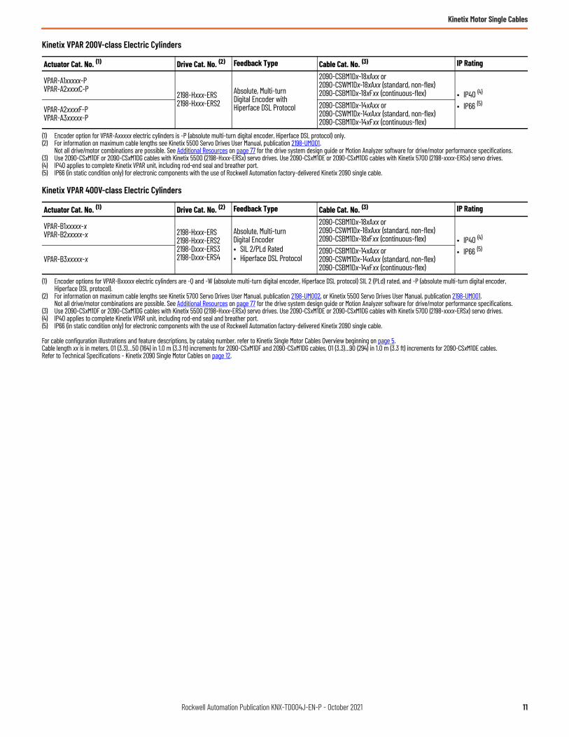
Kinetix VPAR 200V-class Electric Cylinders
Kinetix VPAR 400V-class Electric Cylinders
For cable configuration illustrations and feature descriptions, by catalog number, refer to Kinetix Single Motor Cables Overview beginning on page 5.Cable length xx is in meters, 01 (3.3)…50 (164) in 1.0 m (3.3 ft) increments for 2090-CSxM1DF and 2090-CSxM1DG cables, 01 (3.3)…90 (294) in 1.0 m (3.3 ft) increments for 2090-CSxM1DE cables. Refer to Technical Specifications - Kinetix 2090 Single Motor Cables on page 12.
Actuator Cat. No. (1)
(1) Encoder option for VPAR-Axxxxx electric cylinders is -P (absolute multi-turn digital encoder, Hiperface DSL protocol) only.
Drive Cat. No. (2)
(2) For information on maximum cable lengths see Kinetix 5500 Servo Drives User Manual, publication 2198-UM001.Not all drive/motor combinations are possible. See Additional Resources on page 77 for the drive system design guide or Motion Analyzer software for drive/motor performance specifications.
Feedback Type Cable Cat. No. (3)
(3) Use 2090-CSxM1DF or 2090-CSxM1DG cables with Kinetix 5500 (2198-Hxxx-ERSx) servo drives. Use 2090-CSxM1DE or 2090-CSxM1DG cables with Kinetix 5700 (2198-xxxx-ERSx) servo drives.
IP Rating
VPAR-A1xxxxx-PVPAR-A2xxxxC-P
2198-Hxxx-ERS2198-Hxxx-ERS2
Absolute, Multi-turn Digital Encoder with Hiperface DSL Protocol
2090-CSBM1Dx-18xAxx or2090-CSWM1Dx-18xAxx (standard, non-flex)2090-CSBM1Dx-18xFxx (continuous-flex) • IP40 (4)
• IP66 (5)
(4) IP40 applies to complete Kinetix VPAR unit, including rod-end seal and breather port.(5) IP66 (in static condition only) for electronic components with the use of Rockwell Automation factory-delivered Kinetix 2090 single cable.
VPAR-A2xxxxF-PVPAR-A3xxxxx-P
2090-CSBM1Dx-14xAxx or2090-CSWM1Dx-14xAxx (standard, non-flex)2090-CSBM1Dx-14xFxx (continuous-flex)
Actuator Cat. No. (1)
(1) Encoder options for VPAR-Bxxxxx electric cylinders are -Q and -W (absolute multi-turn digital encoder, Hiperface DSL protocol) SIL 2 (PLd) rated, and -P (absolute multi-turn digital encoder, Hiperface DSL protocol).
Drive Cat. No. (2)
(2) For information on maximum cable lengths see Kinetix 5700 Servo Drives User Manual, publication 2198-UM002, or Kinetix 5500 Servo Drives User Manual, publication 2198-UM001.Not all drive/motor combinations are possible. See Additional Resources on page 77 for the drive system design guide or Motion Analyzer software for drive/motor performance specifications.
Feedback Type Cable Cat. No. (3)
(3) Use 2090-CSxM1DF or 2090-CSxM1DG cables with Kinetix 5500 (2198-Hxxx-ERSx) servo drives. Use 2090-CSxM1DE or 2090-CSxM1DG cables with Kinetix 5700 (2198-xxxx-ERSx) servo drives.
IP Rating
VPAR-B1xxxxx-xVPAR-B2xxxxx-x 2198-Hxxx-ERS
2198-Hxxx-ERS22198-Dxxx-ERS32198-Dxxx-ERS4
Absolute, Multi-turn Digital Encoder• SIL 2/PLd Rated• Hiperface DSL Protocol
2090-CSBM1Dx-18xAxx or2090-CSWM1Dx-18xAxx (standard, non-flex)2090-CSBM1Dx-18xFxx (continuous-flex) • IP40 (4)
• IP66 (5)
(4) IP40 applies to complete Kinetix VPAR unit, including rod-end seal and breather port.(5) IP66 (in static condition only) for electronic components with the use of Rockwell Automation factory-delivered Kinetix 2090 single cable.
VPAR-B3xxxxx-x2090-CSBM1Dx-14xAxx or2090-CSWM1Dx-14xAxx (standard, non-flex)2090-CSBM1Dx-14xFxx (continuous-flex)
Rockwell Automation Publication KNX-TD004J-EN-P - October 2021 11

Kinetix Motor Single Cables
Technical Specifications - Kinetix 2090 Single Motor Cables
2090-CSxM1DE Cable Specifications
IMPORTANT Maximum motor cable length depends on the feedback type and overall system design. The drive-system power supply, AC input-power type, and AC input voltage are among the configuration variables. For more information on maximum cable lengths see your servo drive user manual or the Kinetix 5700, 5500, 5300, 5100 Servo Drives Technical Data, publicationKNX-TD003.
Cable Cat. No. Cable Type/Jacket Color Description Wire Size
AWGWeight, approxkg/m (lb/ft)
Standard Cable Lengthsm (ft)
2090-CSBM1DE-18AAxx
Standard (non-flex) cable, Industrial TPE, Orange (DESINA, RAL 2003)
1000V hybrid cable with four power, two feedback (digital communication), and two brake conductors.
18 0.212 (0.143)
01 (3.3)…90 (295) in 1.0 m (3.3 ft) increments
2090-CSBM1DE-14AAxx 14 0.261 (0.175)
2090-CSWM1DE-18AAxx 1000V hybrid cable with four power and two feedback (digital communication) conductors.
18 0.136 (0.091)
2090-CSWM1DE-14AAxx 14 0.185 (0.124)
2090-CSBM1DE-18AFxx
Continuous-flex cable, Industrial TPE, Orange (DESINA, RAL 2003)
1000V hybrid cable with four power, two feedback (digital communication), and two brake conductors.
18 0.228 (0.153)2090-CSBM1DE-14AFxx 14 0.289 (0.194)2090-CSBM1DE-10AFxx 10 0.551 (0.370)2090-CSBM1DE-08AFxx 8 1.0 (0.67)2090-CSBM1DE-06AFxx 6 1.2 (0.80)2090-CSBM1DE-18VAxx
Standard (non-flex) cable, PVC, Orange (DESINA, RAL 2003)
1000V hybrid cable with four power, two feedback (digital communication), and two brake conductors.
18 0.248 (0.167)51 (167)…90 (295) in 1.0 m (3.3 ft) increments2090-CSBM1DE-14VAxx 14 0.336 (0.226)
2090-CSBM1DE-10VAxx 10 0.514 (0.345)2090-CSBM1DE-08VAxx 8 0.785 (0.527) 01 (3.3)…90 (295)
in 1.0 m (3.3 ft) increments 2090-CSBM1DE-06VAxx 6 1.11 (0.75)2090-CSWM1DE-18VAxx 1000V hybrid cable with four power and
two feedback (digital communication) conductors.
18 0.222 (0.149)
51 (167)…90 (295) in 1.0 m (3.3 ft) increments
2090-CSWM1DE-14VAxx 14 0.264 (0.177)
2090-CSBM1DE-18LFxx
Continuous-flex cable, PUR, Orange (DESINA, RAL 2003)
1000V hybrid cable with four power, two feedback (digital communication), and two brake conductors.
18 0.239 (0.160)2090-CSBM1DE-14LFxx 14 0.317 (0.213)2090-CSBM1DE-10LFxx 10 0.489 (0.329)2090-CSBM1DE-08LFxx 8 0.76 (0.511) 01 (3.3)…90 (295)
in 1.0 m (3.3 ft) increments 2090-CSBM1DE-06LFxx 6 1.08 (0.73)
12 Rockwell Automation Publication KNX-TD004J-EN-P - October 2021

Kinetix Motor Single Cables
Single Extension Cable Specifications
2090-CSxM1DF/DG Cable Specifications
Cable Cat. No. Cable Type/Jacket Color Description Wire Size
AWGWeight, approxkg/m (lb/ft)
Standard Cable Lengthsm (ft)
2090-CSBM1DF-18AAxx2090-CSBM1DG-18AAxx
Standard (non-flex) cable, Industrial TPE, Orange (DESINA, RAL 2003)
1000V hybrid cable with four power, two feedback (digital communication), and two brake conductors.
18 0.212 (0.143)
01 (3.3)…50 (164) in 1.0 m (3.3 ft) increments
2090-CSBM1DF-14AAxx2090-CSBM1DG-14AAxx 14 0.261 (0.175)
2090-CSWM1DF-18AAxx2090-CSWM1DG-18AAxx 1000V hybrid cable with four power and
two feedback (digital communication) conductors.
18 0.136 (0.091)
2090-CSWM1DF-14AAxx2090-CSWM1DG-14AAxx 14 0.185 (0.124)
2090-CSBM1DF-18AFxx2090-CSBM1DG-18AFxx
Continuous-flex cable, Industrial TPE, Orange (DESINA, RAL 2003)
1000V hybrid cable with four power, two feedback (digital communication), and two brake conductors.
18 0.228 (0.153)
01 (3.3)…50 (164) (1)in 1.0 m (3.3 ft) increments
(1) Applies to all Kinetix 5500 (frame 2 and 3) drives. For Kinetix 5500 (frame 1) drives in continuous-flex applications, 30 m (98 ft) is maximum cable length.
2090-CSBM1DF-14AFxx2090-CSBM1DG-14AFxx 14 0.289 (0.194)
2090-CSBM1DF-10AFxx2090-CSBM1DG-10AFxx 10 0.551 (0.370)
2090-CSBM1DG-18VAxx
Standard (non-flex) cable, PVC, Orange (DESINA, RAL 2003)
1000V hybrid cable with four power, two feedback (digital communication), and two brake conductors.
18 0.248 (0.167)
01 (3.3)…50 (164) in 1.0 m (3.3 ft) increments
2090-CSBM1DG-14VAxx 14 0.336 (0.226)2090-CSBM1DG-10VAxx 10 0.514 (0.345)2090-CSWM1DG-18VAxx 1000V hybrid cable with four power and
two feedback (digital communication) conductors.
18 0.222 (0.149)
2090-CSWM1DG-14VAxx 14 0.264 (0.177)
2090-CSBM1DG-18LFxx Continuous-flex cable, PUR, Orange (DESINA, RAL 2003)
1000V hybrid cable with four power, two feedback (digital communication), and two brake conductors.
18 0.239 (0.160)01 (3.3)…50 (164) (1)in 1.0 m (3.3 ft) increments 2090-CSBM1DG-14LFxx 14 0.317 (0.213)
2090-CSBM1DG-10LFxx 10 0.489 (0.329)
Extension Cable (1)Cat. No.
(1) 2090-CSBM1E1-xxAFxx extension cables are UL Listed, bulk cable, type PLTC-ER.
Cable Type/Jacket Color Description Weight, approx
kg/m (lb/ft)Standard Cable Lengthsm (ft)
2090-CSBM1E1-18AFxx
Continuous-flex cable, Industrial TPE, Orange (DESINA, RAL 2003)
SpeedTec DIN connector plug on motor end to SpeedTec DIN receptacle for mating with Kinetix 2090 standard, power/brake/feedback cable, 600V.
0.228 (0.153)
01 (3.3)…30 (98.4) in 1.0 m (3.3 ft) increments
2090-CSBM1E1-14AFxx 0.289 (0.194)2090-CSBM1E1-10AFxx 0.551 (0.370)2090-CSBM1E1-08AFxx 1.0 (0.67)2090-CSBM1E1-06AFxx 1.2 (0.80)2090-CSBM1E1-18VAxx
Standard (non-flex) cable, PVC, Orange (DESINA, RAL 2003)
SpeedTec DIN connector plug on motor end to SpeedTec DIN receptacle for mating with Kinetix 2090 power/brake/feedback cable.
0.248 (0.167)
01 (3.3)…30 (98.4) in 1.0 m (3.3 ft) increments
2090-CSBM1E1-14VAxx 0.336 (0.226)2090-CSBM1E1-10VAxx 0.514 (0.345)2090-CSBM1E1-08VAxx 0.785 (0.527)2090-CSBM1E1-06VAxx 1.11 (0.75)2090-CSBM1E1-18LFxx
Continuous-flex cable, PUR, Orange (DESINA, RAL 2003)
0.239 (0.160)2090-CSBM1E1-14LFxx 0.317 (0.213)2090-CSBM1E1-10LFxx 0.489 (0.329)2090-CSBM1E1-08LFxx 0.76 (0.511)2090-CSBM1E1-06LFxx 1.08 (0.73)
Rockwell Automation Publication KNX-TD004J-EN-P - October 2021 13
Kinetix Motor Single Cables
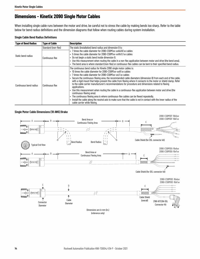
Dimensions - Kinetix 2090 Single Motor Cables
When installing single cable runs between the motor and drive, be careful not to stress the cable by making bends too sharp. Refer to the table below for bend radius definitions and the dimension diagrams that follow when routing cables during system installation.
Single Cable Bend Radius Definitions
Single Motor Cable Dimensions (18 AWG) Brake
Type of Bend Radius Type of Cable Description
Static bend radius
Standard (non-flex) The static (installation) bend radius and dimension B is:• 7 times the cable diameter for 2090-CSBM1xx-xxAA/AFxx cables• 5 times the cable diameter for 2090-CSBM1xx-xxVA/LFxx cables• Do not begin a static bend inside dimension B.• Use this measurement when routing the cable in a non-flex application between motor and drive (the bend area).• The bend area is where standard (non-flex) or continuous-flex cables can be bent to their specified bend radius.
Continuous flex
Continuous bend radius Continuous flex
The continuous bend radius for Kinetix 2090 single motor cables is:• 10 times the cable diameter for 2090-CSBM1xx-xxAFxx cables• 7 times the cable diameter for 2090-CSBM1xx-xxLFxx cables• Secure the continuous-flexing area, the recommended cable diameters (dimension B) from each end of the cable,
with a rigid mount that helps prevent the cable from flexing where it connects to the motor or shield clamp. Refer to the cable carrier manufacturer's recommendations for procedure and dimensions related to flexing applications.
• Use this measurement when routing the cable in a continuous-flex application between motor and drive (the continuous-flexing area).
• The continuous flexing area is where continuous-flex cables can be flexed repeatedly.• Install the cable along the neutral axis to make sure that the cable is not in contact with the inner radius of the
cable carrier while flexing.
2090-CSBM1DF-18AAxx2090-CSBM1DF-18AFxx
DC
A B B
2090-CSBM1DE-18xAxx2090-CSBM1DE-18xFxx
E
E
2090-CSBM1DG-18xAxx2090-CSBM1DG-18xFxx
A B B E
Bend Radius
Dimensions are in mm (in.)(reference only)
Typical End View
CableDiameterConnector
Diameter
Cable Shield (for DSL connector kit)
Cable Shield (for DSL connector kit)
Cable Shield(overall)
Bend Radius
Bend Area orContinuous Flexing Area
2198-KITCON-DSLConnector Kit
Bend Area orContinuous Flexing Area
14 Rockwell Automation Publication KNX-TD004J-EN-P - October 2021

Kinetix Motor Single Cables
Single Motor Cable Dimensions (18 AWG) Without Brake
Single Motor Cable Dimensions (18 AWG)
Cable Cat. No. Amm (in.)
B (1)
mm (in.)
(1) Dimension B and Continuous Bend Radius are based on the cable diameter. Refer to Single Cable Bend Radius Definitions on page 14 for more information.
Continuous Bend Radius (1)mm (in.)
Cmm (in.)
Dmm (in.)
Emm (in.)
2090-CSBM1DF-18AAxx
81.0 (3.2) 105 (4.1)
–
28.0 (1.1) 15.0 (0.59)
41.0 (1.6)
2090-CSBM1DE-18AAxx71.0 (2.8)
2090-CSBM1DG-18AAxx
2090-CSWM1DF-18AAxx 41.0 (1.6)
2090-CSWM1DE-18AAxx71.0 (2.8)
2090-CSWM1DG-18AAxx
2090-CSBM1DF-18AFxx
150 (5.9)
41.0 (1.6)
2090-CSBM1DE-18AFxx71.0 (2.8)
2090-CSBM1DG-18AFxx
2090-CSBM1DE-18VAxx
81.0 (3.2)
92.4 (3.6)
–
28.0 (1.1)
13.2 (0.52)
71. (2.8)
2090-CSBM1DG-18VAxx
2090-CSWM1DE-18VAxx85.4 (3.4) 12.2 (0.48)
2090-CSWM1DG-18VAxx
2090-CSBM1DE-18LFxx92.4 (3.6) 92.4 (3.6) 13.2 (0.52)
2090-CSBM1DG-18LFxx
2090-CSWM1DF-18AAxx
DC
A B B
2090-CSWM1DE-18xAxxE
E
2090-CSWM1DG-18xAxxA B B E
Bend Radius
Dimensions are in mm (in.)(reference only)
Typical End View
CableDiameterConnector
Diameter
Cable Shield (DSL connector kit)
Cable Shield (for DSL connector kit)
Cable Shield(overall)
Bend Radius
Bend Area orContinuous Flexing Area
2198-KITCON-DSLConnector Kit
Bend Area orContinuous Flexing Area
Rockwell Automation Publication KNX-TD004J-EN-P - October 2021 15
Kinetix Motor Single Cables
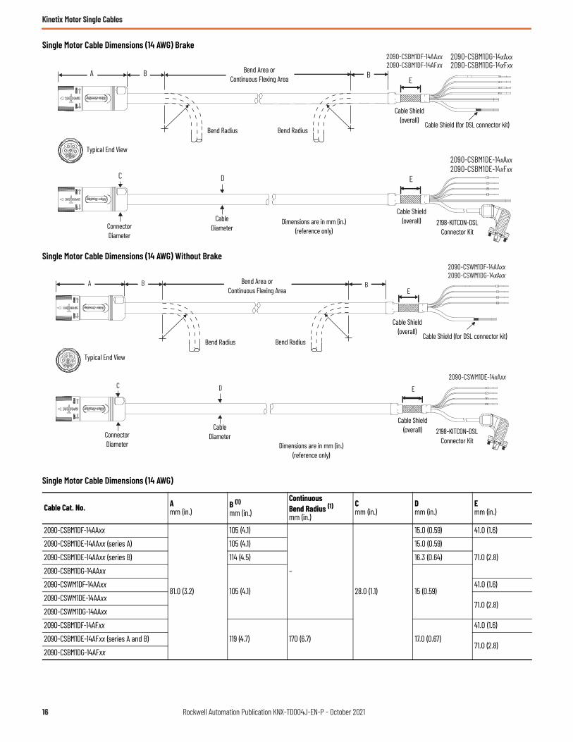
Single Motor Cable Dimensions (14 AWG) Brake
Single Motor Cable Dimensions (14 AWG) Without Brake
Single Motor Cable Dimensions (14 AWG)
Cable Cat. No. Amm (in.)
B (1)mm (in.)
Continuous Bend Radius (1)mm (in.)
Cmm (in.)
Dmm (in.)
Emm (in.)
2090-CSBM1DF-14AAxx
81.0 (3.2)
105 (4.1)
–
28.0 (1.1)
15.0 (0.59) 41.0 (1.6)
2090-CSBM1DE-14AAxx (series A) 105 (4.1) 15.0 (0.59)
71.0 (2.8)2090-CSBM1DE-14AAxx (series B) 114 (4.5) 16.3 (0.64)
2090-CSBM1DG-14AAxx
105 (4.1) 15 (0.59)2090-CSWM1DF-14AAxx 41.0 (1.6)
2090-CSWM1DE-14AAxx71.0 (2.8)
2090-CSWM1DG-14AAxx
2090-CSBM1DF-14AFxx
119 (4.7) 170 (6.7) 17.0 (0.67)
41.0 (1.6)
2090-CSBM1DE-14AFxx (series A and B)71.0 (2.8)
2090-CSBM1DG-14AFxx
2090-CSBM1DG-14xAxx2090-CSBM1DG-14xFxx
A
DC
B B
2090-CSBM1DE-14xAxx2090-CSBM1DE-14xFxx
E
2090-CSBM1DF-14AAxx2090-CSBM1DF-14AFxx
E
Bend Radius
Dimensions are in mm (in.)(reference only)
Typical End View
CableDiameterConnector
Diameter
Cable Shield(overall) Cable Shield (for DSL connector kit)
Cable Shield(overall) 2198-KITCON-DSL
Connector Kit
Bend Area orContinuous Flexing Area
Bend Radius
A
2090-CSWM1DE-14xAxxDC
B B
E
2090-CSWM1DF-14AAxx2090-CSWM1DG-14xAxx
E
Bend Radius
Dimensions are in mm (in.)(reference only)
Typical End View
CableDiameterConnector
Diameter
Cable Shield(overall) Cable Shield (for DSL connector kit)
Cable Shield(overall)
Bend Area orContinuous Flexing Area
Bend Radius
2198-KITCON-DSLConnector Kit
16 Rockwell Automation Publication KNX-TD004J-EN-P - October 2021

Kinetix Motor Single Cables
Single Motor Cable Dimensions (10, 8, and 6 AWG)
2090-CSBM1DE-14VAxx
81 (3.2)
106.4 (4.2)
N/A
28 (1.1)
15.2 (0.60)
71 (2.8)
2090-CSBM1DG-14VAxx
2090-CSWM1DE-14VAxx91 (3.6) 13 (0.51)
2090-CSWM1DG-14VAxx
2090-CSBM1DE-14LFxx106.4 (4.2) 106.4 (4.2) 15.2 (0.60)
2090-CSBM1DG-14LFxx
(1) Dimension B and Continuous Bend Radius are based on the cable diameter. Refer to Single Cable Bend Radius Definitions on page 14 for more information.
Single Motor Cable Dimensions (10, 8, and 6 AWG)
Cable Cat. No. Amm (in.)
B (1)mm (in.)
(1) Dimension B and Continuous Bend Radius are based on the cable diameter. Refer to Single Cable Bend Radius Definitions on page 14 for more information.
Continuous Bend Radius (1)mm (in.)
Cmm (in.)
Dmm (in.)
Emm (in.)
2090-CSBM1DF-10AFxx
100 (4.0)
133 (5.2) 190 (7.5)
46 (1.8)
19.0 (0.75)
50.8 (2.0)
2090-CSBM1DG-10AFxx
71.0 (2.8)2090-CSBM1DE-10AFxx (series A)
2090-CSBM1DE-10AFxx (series B) 142 (5.6) 203 (8.0) 20.3 (0.80)
2090-CSBM1DE-08AFxx200 (8.0) 250 (10.0) 25.0 (0.98) 89.0 (3.5)
2090-CSBM1DE-06AFxx
2090-CSBM1DG-10VAxx
100 (4.0)
126 (5.0)
—
46 (1.8)
18.0 (0.71)
76.3 (3.0)2090-CSBM1DG-10LFxx 126 (5.0)
2090-CSBM1DE-10VAxx —71.0 (2.8)
2090-CSBM1DE-10LFxx 126 (5.0)
2090-CSBM1DE-08VAxx151.2 (5.9)
—21.6 (0.85) 89.0 (3.5)
2090-CSBM1DE-08LFxx 151.2 (5.9)
2090-CSBM1DE-06VAxx168 (6.6)
—24.0 (0.94) 89.0 (3.5)
2090-CSBM1DE-06LFxx 168 (6.6)
Single Motor Cable Dimensions (14 AWG) (Continued)
Cable Cat. No. Amm (in.)
B (1)mm (in.)
Continuous Bend Radius (1)mm (in.)
Cmm (in.)
Dmm (in.)
Emm (in.)
2090-CSBM1DF-10AFxx2090-CSBM1DG-10xFxx2090-CSBM1DG-10VAxx
C
A
E
2090-CSBM1DE-08xFxx2090-CSBM1DE-08VAxx2090-CSBM1DE-06xFxx2090-CSBM1DE-06VAxx
ED
B B
2090-CSBM1DE-10xFxx2090-CSBM1DE-10VAxx
Bend Radius
Dimensions are in mm (in.)(reference only)
Typical End View
CableDiameterConnector
Diameter
Cable Shield (for DSL connector kit)
Cable Shield(overall)
Bend Area orContinuous Flexing Area
Cable Shield(overall)
2198-KITCON-DSLConnector Kit
Rockwell Automation Publication KNX-TD004J-EN-P - October 2021 17

Kinetix Motor Single Cables
Dimensions - Single Extension CablesExtension Cable Dimensions
Extension Cable Dimensions
Extension CableCat. No.
Amm (in.)
B (1)mm (in.)
(1) Dimension B and Continuous Bend Radius are based on the cable diameter. Refer to Single Cable Bend Radius Definitions on page 14 for more information.
ContinuousBend Radius (1)mm (in.)
Cmm (in.)
Dmm (in.)
2090-CSBM1E1-18AFxx
81.0 (3.2)
105 (4.1) 150 (5.9)
28 (1.1)
15.0 (0.59)
2090-CSBM1E1-18LFxx92.4 (3.6)
92.4 (3.6)13.2 (0.52)
2090-CSBM1E1-18VAxx –
2090-CSBM1E1-14AFxx (series A and B) 119 (4.7) 170 (6.7) 17.0 (0.67)
2090-CSBM1E1-14LFxx106.4 (4.2)
106.4 (4.2)15.2 (0.60)
2090-CSBM1E1-14VAxx –
2090-CSBM1E1-10AFxx (series A)
100 (4.0)
133 (5.2) 190 (7.5)
46 (1.8)
19.0 (0.75)
2090-CSBM1E1-10AFxx (series B) 142 (5.6) 203 (8.0) 20.3 (0.80)
2090-CSBM1E1-10LFxx126 (5.0)
126 (5.0)18.0 (0.70)
2090-CSBM1E1-10VAxx –
2090-CSBM1E1-08AFxx 200 (8.0) 250 (10.0) 25.0 (0.98)
2090-CSBM1E1-08LFxx151.2 (5.9)
151.2 (5.9)21.6 (0.85)
2090-CSBM1E1-08VAxx –
2090-CSBM1E1-06AFxx 200 (8.0) 250 (10.0) 25.0 (0.98)
2090-CSBM1E1-06LFxx168 (6.6)
168 (6.6)24.0 (0.94)
2090-CSBM1E1-06VAxx –
2090-CSBM1E1-18xFxx2090-CSBM1E1-18VAxx2090-CSBM1E1-14xFxx2090-CSBM1E1-14VAxx
A B B A
DC
A B B A
V
–W 21
U
+ NHL
2090-CSBM1E1-10xFxx2090-CSBM1E1-10VAxx2090-CSBM1E1-08xFxx2090-CSBM1E1-08VAxx2090-CSBM1E1-06xFxx2090-CSBM1E1-06VAxx
Bend RadiusDimensions are in mm (in.)
(reference only)
CableDiameterConnector
Diameter
Bend Area orContinuous Flexing Area
Bend Radius Bend Radius
Bend Area orContinuous Flexing Area
18 Rockwell Automation Publication KNX-TD004J-EN-P - October 2021

Kinetix Motor Single Cables
Kinetix 2090 Single Cable Bulkhead Adapter Kits
These bulkhead adapter kits let you secure your single cables as they pass through the cabinet. For bulkhead adapter dimensions, see Bulkhead Adapter Kit Dimensions on page 56.
Kinetix 2090 Single Motor Cable Compatibility
Bulkhead Adapter Cat. No.
Standard (non-flex) (1)Power Cable Cat. No.
(1) Cable catalog numbers extended with DF/DE/DG reflects 2090-CSxM1DF, 2090-CSxM1DE, and 2090-CSxM1DG cables.
Continuous-flex (1)Power Cable Cat. No. Description
Connector Diametermm (in.)
2090-KPB47-12CF
2090-CSWM1DE/DG-18xAxx2090-CSWM1DF-18AAxx
2090-CSWM1DE/DG-18xFxx2090-CSWM1DF-18AFxx
Power/feedback
SpeedTec DIN 28.0 (1.1)
2090-CSWM1DE/DG-14xAxx2090-CSWM1DF-14AAxx
2090-CSWM1DE/DG-14xFxx2090-CSWM1DF-14AFxx
2090-CSBM1DE/DG-18xAxx2090-CSBM1DF-18AAxx
2090-CSBM1DE/DG-18xFxx2090-CSBM1DF-18AFxx
Power/brake/feedback
2090-CSBM1DE/DG-14xAxx2090-CSBM1DF-14AAxx
2090-CSBM1DE/DG-14xFxx2090-CSBM1DF-14AFxx
2090-CSBM1E1-18VAxx 2090-CSBM1E1-18xFxx
2090-CSBM1E1-14VAxx 2090-CSBM1E1-14xFxx
2090-KPB47-06CF
2090-CSBM1DE/DG-10xAxx2090-CSBM1DF-10AAxx
2090-CSBM1DE/DG-10xFxx2090-CSBM1DF-10AFxx
Power/brake/feedback SpeedTec DIN 46.0 (1.8)
2090-CSBM1DE-08VAxx 2090-CSBM1DE-08xFxx
2090-CSBM1DE-06VAxx 2090-CSBM1DE-06xFxx
2090-CSBM1E1-10VAxx 2090-CSBM1E1-10xFxx
2090-CSBM1E1-08VAxx 2090-CSBM1E1-08xFxx
2090-CSBM1E1-06VAxx 2090-CSBM1E1-06xFxx
Rockwell Automation Publication KNX-TD004J-EN-P - October 2021 19

Kinetix Motor Power and Feedback Cables
Kinetix Motor Power and Feedback CablesA wide variety of power and feedback cables with rugged DIN connectors are available for connecting your motion control system. Standard (non-flex) motor power and feedback cables are available for all Allen-Bradley servo motors and actuators. Continuous-flex rated cables, intended for moving applications, are also available. Continuous-flex extension and standard (non-flex) transition cables are also available for your applications that require them.
Catalog Numbers - Kinetix Power and Feedback Cables
Catalog numbers consist of various characters, each of which identifies a specific option for that component. Use the catalog numbering charts below to understand the configuration of your component. For questions regarding product availability, contact your Allen-Bradley distributor.
Motor Power/Brake, Feedback, and Extension Cables
IMPORTANT All flying-lead feedback cables require breakout components or connector kits for drive-end terminations. Refer to Breakout Components and Connector Kits in Kinetix 3, 300, 350, 2000, 6000, 6200, 6500, 7000 Servo Drives Specifications, publication KNX-TD005 for catalog numbers and descriptions.
IMPORTANT Standard (non-flex) cables have a regular maintenance and installation bend radius of 7 times the cable diameter. For flexing applications, continuous-flex cables have an operational bend radius of 12 times the cable diameter.
2090 - C xx Mx Dx - Cx Ax xx
Cable LengthRefer to Technical Specifications - Kinetix Motor Power and Feedback Cables beginning on page 41.
Wire Gauge Size (applies to power cables)16, 14, 12, 10, 8, 6, 4, and 2 AWG
Cable TypePB = Motor power with brake wiresPW = Motor power onlyFB = Motor feedback only
Cable TypeAA = Standard, non-flexAF = Continuous-flex
Accessory ComponentC = CableBulletin Number
Motor-end Connector TypeM6 = Circular plastic connectorM4 = Threaded DIN connectorM7 = SpeedTec DIN connector
Drive-end Connector TypeDF = Drive-end, flying-leadDD = Drive-end, D-sub connectorE7 = Extension receptacle (SpeedTec ready)
Encoder Type (applies to feedback cables)CB = Serial incremental/Serial absolute - battery backupCC = Serial incremental/IncrementalCD = SIN/COS High-resolution/IncrementalCE = SIN/COS High-resolution/Resolver
20 Rockwell Automation Publication KNX-TD004J-EN-P - October 2021

Kinetix Motor Power and Feedback Cables
Transition Cables
Motor Power, Feedback, and Brake Cables
Cat. No. Cable GaugeAWG Cable Type Description
2090-CPBM4E2-14TR 14 and 16
Power/brake
Threaded DIN connector (M4) on motor-end to bayonet receptacle (E2) for mating with existing bayonet cable, 500 mm (19.7 in.).
2090-CPBM4E2-10TR 102090-CPBM4E2-08TR 82090-CPBM4E2-04TR 4 and 62090-CPWM4E2-14TR 14 and 16
Power (only)2090-CPWM4E2-10TR 102090-CPWM4E2-08TR 82090-CPWM4E2-04TR 4 and 62090-CFBM4E2-CATR N/A Feedback
2090 - xx x xx xx - xx S xxCable LengthRefer to Technical Specifications - Kinetix Motor Power and Feedback Cables beginning on page 41.Motor ConnectorS = StraightWire Gauge Size (AWG) 16 = Motor power cable18 = Motor brake cablesBlank = Feedback cablesMotor/Actuator SeriesMF = Threaded DIN ConnectorsMPS-A/Bxxxx (MPS-A/Bxxxx-M/S)HPK-B/Exxxx (HPK-B/Exxxxx-M/S)MPAS-A/Bxxxx (MPAS-A/Bxxxxx-V/A) or MPMA-A/BxxxxT = TL-Axxxx-BCable TypeP = Motor powerF = Motor feedback connector (flying-leads at drive)FC = Motor feedback (connectors at both ends, Kinetix TL and TLYFM = Motor feedback (flying-leads to D-sub at drive)B = Motor brakeFlex OptionN = Standard cable (non-flex)
Drive FamilyDA = Kinetix 5300, Kinetix 5100, Kinetix 3 drivesXX = All other drivesBulletin Number
Rockwell Automation Publication KNX-TD004J-EN-P - October 2021 21

Kinetix Motor Power and Feedback Cables
Kinetix Power and Feedback Cables OverviewFeedback Cable Descriptions (standard, non-flex)
Feedback Cable Descriptions (continuous-flex)
Standard Cable Cat. No. Description
Cable ConfigurationConnector Type
Motor End Drive End
2090-CFBM7DF-CEAAxx • Drive-end flying-leads (DF)• High-resolution or resolver applications (CE)
SpeedTec DIN(M7)
2090-CFBM7DD-CEAAxx • Drive-end 15-pin connector (DD)• High-resolution or resolver applications (CE)
2090-XXNFMF-Sxx • Drive-end flying-leads• High-resolution or incremental applications
Threaded DIN(M4)
2090-CFBM4E2-CATR• Drive-end bayonet (E2), transition (TR) cable (1)• Motor-end threaded DIN (M4)• All feedback types (CA)
(1) Threaded DIN connector (motor end) and bayonet connector for 2090-XXNFMP-Sxx cable. Refer to Kinetix Motor Power and Feedback Transition Cables on page 26.
Continuous-flex Cable Cat. No. Description
Cable ConfigurationConnector Type
Motor End Drive End
2090-CFBM7DF-CDAFxx • Drive-end flying-leads (DF)• High-resolution or incremental applications (CD)
SpeedTec DIN(M7)
2090-CFBM7DF-CEAFxx • Drive-end flying-leads (DF)• High-resolution or resolver applications (CE)
2090-CFBM7DD-CEAFxx • Drive-end 15-pin connector (DD)• High-resolution or resolver applications (CE)
2090-CFBM7E7-CDAFxx • Drive-end (male) connector, extension (E7) (1)• Motor-end SpeedTec DIN cable plug (M7)
(1) SpeedTec DIN connector (motor end) and male connector for extending SpeedTec or threaded DIN cable. Refer to SpeedTec DIN Continuous-flex Extension Cables on page 25.
2090-CFBM7E7-CEAFxx
2090-CFBM4DF-CDAFxx • Drive-end flying-leads• High-resolution or incremental applications
Threaded DIN(M4)
IMPORTANT Feedback cables with the CE designation, for example 2090-CFBM7DF-CEAAxx, are intended for high-resolution encoder or resolver applications and have fewer conductors than feedback cables with the CD designation, for example, 2090-CFBM7DF-CDAFxx that are intended for high-resolution or incremental encoder applications.
22 Rockwell Automation Publication KNX-TD004J-EN-P - October 2021

Kinetix Motor Power and Feedback Cables
Power/Brake Cable Descriptions (standard, non-flex)
Power/Brake Cable Descriptions (continuous-flex)
Standard Cable Cat. No. Description
Cable ConfigurationConnector Type
Motor End Drive End
2090-CPBM7DF-xxAAxx • Drive-end flying-leads (DF)• Power/brake wires (PB)
SpeedTec DIN(M7)
2090-CPWM7DF-xxAAxx • Drive-end flying-leads (DF)• Power wires only (PW)
2090-XXNPMF-xxSxx • Drive-end flying-leads• Power/brake wires
Threaded DIN(M4)2090-CPBM4E2-xxTR
• Drive-end bayonet (E2), transition (TR) cable (1)• Motor-end threaded DIN (M4)• Power/brake wires (PB)
(1) Threaded DIN connector (motor end) and bayonet connector for 2090-XXNFMP-Sxx cable. Refer to Kinetix Motor Power and Feedback Transition Cables on page 26.
2090-CPWM4E2-xxTR• Drive-end bayonet (E2), transition (TR) cable (1)• Motor-end threaded DIN (M4)• Power wires only (PW)
Continuous-flex Cable Cat. No. Description
Cable ConfigurationConnector Type
Motor End Drive End
2090-CPBM7DF-xxAFxx • Drive-end flying-leads (DF)• Power/brake wires (PB)
SpeedTec DIN(M7)2090-CPWM7DF-xxAFxx • Drive-end flying-leads (DF)
• Power wires only (PW)
2090-CPBM7E7-xxAFxx • Drive-end (male) connector, extension (E7) (1)• Motor-end SpeedTec DIN cable plug (M7)
(1) SpeedTec DIN connector (motor end) and male connector for extending SpeedTec or threaded DIN cable. Refer to SpeedTec DIN Continuous-flex Extension Cables on page 25.
2090-CPBM4DF-xxAFxx • Drive-end flying-leads (DF)• Power/brake wires (PB) Threaded DIN
(M4)
2090-CPWM4DF-xxAFxx • Drive-end flying-leads (DF)• Power wires only (PW)
BR+BR-
BR+BR-
Rockwell Automation Publication KNX-TD004J-EN-P - October 2021 23

Kinetix Motor Power and Feedback Cables
Kinetix Motor Power and Feedback Cables with SpeedTec DIN Connectors Overview
Kinetix power and feedback cables with SpeedTec DIN connectors let OEMs and end-users standardize their machines on a common motor cable family. These cables, designed by Rockwell Automation for optimal performance with Allen-Bradley servo drives, servo motors, and linear actuators, offer best-in-class features and standards compliance. Innovative features, configuration options, and accessories provide machine builders with complete control of the cable requirements in their machines.
SpeedTec DIN Cable Features• NFPA 79 Compliant• UL Listed bulk cable with 600V insulation rating for use in cable trays and exposed run applications.
- Type TC-ER: Power-only and power-with-brake cables- Type PLTC-ER: Feedback cable optimized for high-resolution feedback motors
• CSA AWM, I/II A/B, 600V, 90 °C construction• SpeedTec connection system yields quick connections with positive metallic keying• DESINA compliant jacket coloring (orange for power, green for feedback) for easy identification and separation of cables in a machine• Cables are included in the Rockwell Automation servo system Declaration of Conformity (DoC)• Continuous flex cables are suitable for 20 million flex-cycles
- Continuous-flex cables are also available in extension cable configurations• Comprehensive accessories optimize the use of cables in machines
24 Rockwell Automation Publication KNX-TD004J-EN-P - October 2021

Kinetix Motor Power and Feedback Cables
SpeedTec DIN Continuous-flex Extension Cables
Motor power and feedback extension cables provide continuous-flex cable technology between your standard (non-flex) cable and the continuous-flex application. The IP rating for continuous-flex extension cables is consistent with the motor/actuator and cable combination they are extending. Extension cables are available in lengths up to 30 m (98.4 ft). Extension power cables are available in 16, 14, 10, and 8 AWG.
Typical Extension Cable Application with Bulkhead Adapter
Continuous-flex Extension Feedback Cables
Continuous-flex Extension Power Cables
Continuous-flex Cable Cat. No. Description Applications
2090-CFBM7E7-CDAFxxFeedback extension cable, SpeedTec DIN (male/female) connectors
Intended for high-resolution or incremental encoder applications.
2090-CFBM7E7-CEAFxx Intended for high-resolution encoder or resolver applications.
Continuous-flex Cable Cat. No. Description
2090-CPBM7E7-16AFxx
Power/brake extension cable, SpeedTec DIN (male/female) connectors
2090-CPBM7E7-14AFxx2090-CPBM7E7-10AFxx2090-CPBM7E7-08AFxx
62006200SAFE SPEED
2090-CPBM7E7-xxAFxxContinuous-flex (power/brake)
Extension Cable
Machine withContinuous-flex Cable Application
Servo Drive
Servo Motor2090-CFBM7E7-CDAFxx or2090-CFBM7E7-CEAFxxContinuous-flex (feedback)Extension Cable
2090-XXNFMF-Sxx,2090-CFBM7DF-CEAxxx, or
2090-CFBM7DD-CEAxxx standard (non-flex) Circular DIN Feedback Cables
2090-XXNPMF-xxSxx or2090-CPBM7DF-xxAAxx standard (non-flex)
Circular DIN Power/Brake Cables
2090-KFB47-CFBulkhead Adapter(feedback)
Use the Kinetix 2090 bulkhead adapters to secure your standard (non-flex) cable to the machine or cabinet.
2090-KPB47-xxCFBulkhead Adapter(power/brake)
Rockwell Automation Publication KNX-TD004J-EN-P - October 2021 25

Kinetix Motor Power and Feedback Cables
Kinetix Motor Power and Feedback Transition Cables
Motor power/brake and feedback transition cables support installations where Kinetix MPL motors with bayonet connectors were recently replaced by the same motor with circular DIN connectors. These 0.5 m (19.7 in.) cables provide a seamless transition between your new motor and existing power, brake, and feedback cables.
Bayonet and Circular DIN Motor Connectors
Transition Cable Application (power-only cable)
Transition Cable Application (power/brake cable)
Refer to the transition cable selection tables on page 31 for cable catalog numbers for the specific Kinetix MPL or Kinetix MPM motor you are transitioning to.
Brake contacts for motors with bayonet connectors are in a separate connector. Power/brake cables with circular DIN connectors (either threaded or SpeedTec) include brake contacts in the power/brake connector.
Bayonet Connectorswith Brake
Bayonet Connectorswithout Brake
Feedback / Power Motor Connectors
Feedback / Power / BrakeMotor Connectors
Circular DIN Connectors
Power/BrakeMotor Connector
FeedbackMotor Connector
(threaded or SpeedTec-ready DIN connectors)
Threaded SpeedTec-ready
2090-CPWM4E2-xxTRPower-only Transition Cables
Servo drive in existing application.
Kinetix MPLServo Motor
2090-UXNFBMP-Sxx, and 2090-XXNFMP-Sxx (standard, non-flex) or 2090-XXTFMP-Sxx (continuous-flex)
Bayonet Feedback Cables
2090-XXNPMP-xxSxx (standard, non-flex)or 2090-XXTPMP-xxSxx (continuous-flex)
Bayonet Power Cables
2090-CFBM4E2-CATRFeedback Transition Cables
Machine transitioning from Kinetix MPLservo motor with bayonet connectors to
motor with threaded or SpeedTec-ready DIN connectors.
2090-CPBM4E2-xxTR Power/Brake Transition Cables
Servo drive in existing application.
Kinetix MPLServo Motor
2090-XXNBMP-18Sxx (standard, non-flex) or 2090-XXTBMP-18Sxx (continuous-flex
Bayonet Brake Cables
2090-XXNPMP-xxSxx (standard, non-flex) or 2090-XXTPMP-xxSxx (continuous-flex)
Bayonet Power Cables
Machine transitioning from Kinetix MPLservo motor with bayonet connectors to
motor with threaded or SpeedTec-ready DIN connectors.
2090-XXNFMP-Sxx and2090-UXNFBMP-Sxx (standard, non-flex) or 2090-XXTFMP-Sxx (continuous-flex)
Bayonet Feedback Cables
2090-CFBM4E2-CATRFeedback Transition Cables
26 Rockwell Automation Publication KNX-TD004J-EN-P - October 2021
Kinetix Motor Power and Feedback Cables
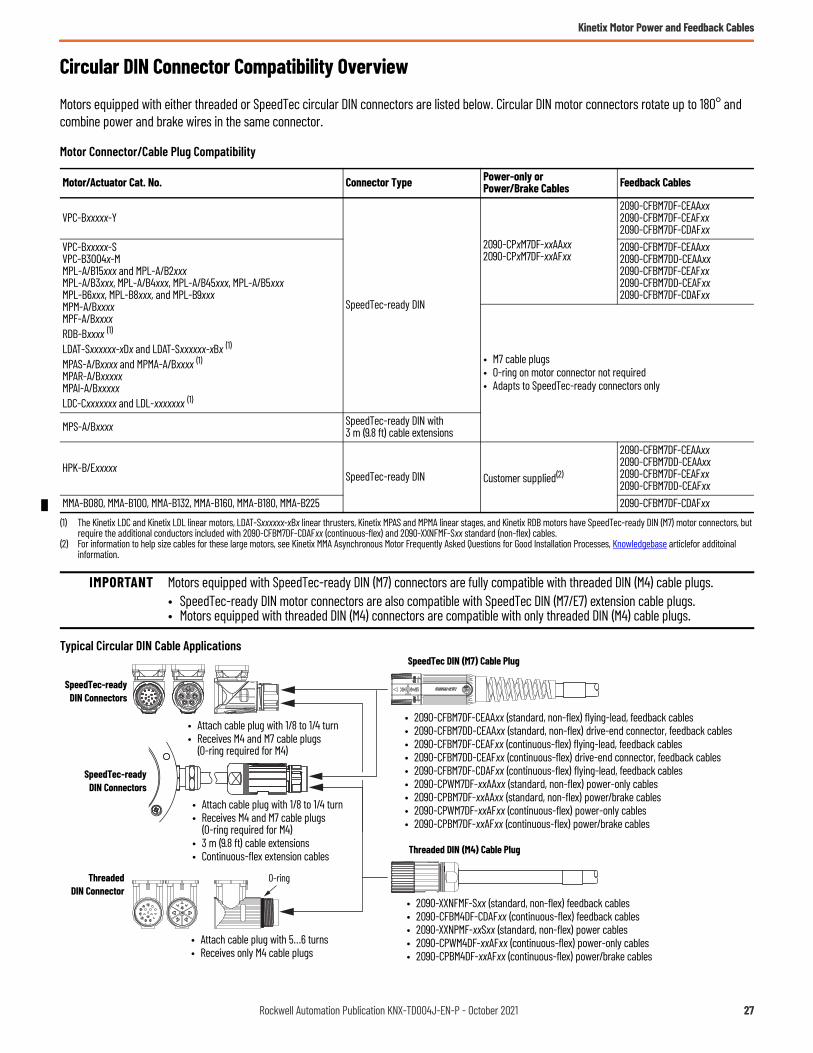
Circular DIN Connector Compatibility Overview
Motors equipped with either threaded or SpeedTec circular DIN connectors are listed below. Circular DIN motor connectors rotate up to 180° and combine power and brake wires in the same connector.
Motor Connector/Cable Plug Compatibility
Typical Circular DIN Cable Applications
Motor/Actuator Cat. No. Connector Type Power-only or Power/Brake Cables Feedback Cables
VPC-Bxxxxx-Y
SpeedTec-ready DIN
2090-CPxM7DF-xxAAxx2090-CPxM7DF-xxAFxx
2090-CFBM7DF-CEAAxx2090-CFBM7DF-CEAFxx2090-CFBM7DF-CDAFxx
VPC-Bxxxxx-SVPC-B3004x-MMPL-A/B15xxx and MPL-A/B2xxxMPL-A/B3xxx, MPL-A/B4xxx, MPL-A/B45xxx, MPL-A/B5xxxMPL-B6xxx, MPL-B8xxx, and MPL-B9xxxMPM-A/BxxxxMPF-A/BxxxxRDB-Bxxxx (1)
LDAT-Sxxxxxx-xDx and LDAT-Sxxxxxx-xBx (1)
MPAS-A/Bxxxx and MPMA-A/Bxxxx (1)MPAR-A/BxxxxxMPAI-A/BxxxxxLDC-Cxxxxxxx and LDL-xxxxxxx (1)
(1) The Kinetix LDC and Kinetix LDL linear motors, LDAT-Sxxxxxx-xBx linear thrusters, Kinetix MPAS and MPMA linear stages, and Kinetix RDB motors have SpeedTec-ready DIN (M7) motor connectors, but require the additional conductors included with 2090-CFBM7DF-CDAFxx (continuous-flex) and 2090-XXNFMF-Sxx standard (non-flex) cables.
2090-CFBM7DF-CEAAxx2090-CFBM7DD-CEAAxx2090-CFBM7DF-CEAFxx2090-CFBM7DD-CEAFxx2090-CFBM7DF-CDAFxx
• M7 cable plugs• O-ring on motor connector not required• Adapts to SpeedTec-ready connectors only
MPS-A/Bxxxx SpeedTec-ready DIN with3 m (9.8 ft) cable extensions
HPK-B/ExxxxxSpeedTec-ready DIN Customer supplied(2)
(2) For information to help size cables for these large motors, see Kinetix MMA Asynchronous Motor Frequently Asked Questions for Good Installation Processes, Knowledgebase articlefor additoinal information.
2090-CFBM7DF-CEAAxx2090-CFBM7DD-CEAAxx2090-CFBM7DF-CEAFxx2090-CFBM7DD-CEAFxx
MMA-B080, MMA-B100, MMA-B132, MMA-B160, MMA-B180, MMA-B225 2090-CFBM7DF-CDAFxx
IMPORTANT Motors equipped with SpeedTec-ready DIN (M7) connectors are fully compatible with threaded DIN (M4) cable plugs. • SpeedTec-ready DIN motor connectors are also compatible with SpeedTec DIN (M7/E7) extension cable plugs.• Motors equipped with threaded DIN (M4) connectors are compatible with only threaded DIN (M4) cable plugs.
• Attach cable plug with 1/8 to 1/4 turn• Receives M4 and M7 cable plugs
(O-ring required for M4)
SpeedTec-readyDIN Connectors
ThreadedDIN Connector
O-ring
SpeedTec DIN (M7) Cable Plug
Threaded DIN (M4) Cable Plug
• 2090-XXNFMF-Sxx (standard, non-flex) feedback cables• 2090-CFBM4DF-CDAFxx (continuous-flex) feedback cables• 2090-XXNPMF-xxSxx (standard, non-flex) power cables• 2090-CPWM4DF-xxAFxx (continuous-flex) power-only cables• 2090-CPBM4DF-xxAFxx (continuous-flex) power/brake cables
• Attach cable plug with 5…6 turns• Receives only M4 cable plugs
• 2090-CFBM7DF-CEAAxx (standard, non-flex) flying-lead, feedback cables• 2090-CFBM7DD-CEAAxx (standard, non-flex) drive-end connector, feedback cables• 2090-CFBM7DF-CEAFxx (continuous-flex) flying-lead, feedback cables• 2090-CFBM7DD-CEAFxx (continuous-flex) drive-end connector, feedback cables• 2090-CFBM7DF-CDAFxx (continuous-flex) flying-lead, feedback cables• 2090-CPWM7DF-xxAAxx (standard, non-flex) power-only cables• 2090-CPBM7DF-xxAAxx (standard, non-flex) power/brake cables• 2090-CPWM7DF-xxAFxx (continuous-flex) power-only cables• 2090-CPBM7DF-xxAFxx (continuous-flex) power/brake cables
• Attach cable plug with 1/8 to 1/4 turn• Receives M4 and M7 cable plugs
(O-ring required for M4)• 3 m (9.8 ft) cable extensions• Continuous-flex extension cables
SpeedTec-readyDIN Connectors
Rockwell Automation Publication KNX-TD004J-EN-P - October 2021 27

Kinetix Motor Power and Feedback Cables
Kinetix Motor Power and Feedback Cable Selection
These tables provide motor power and feedback cable catalog numbers for use with Allen-Bradley servo motors. Most motor brake wires are in the power cable, so a separate brake cable is not required (except where noted). The IP rating is dependent on the use of Allen-Bradley Kinetix 2090 cables as listed in these tables.
Kinetix 5700 single-axis inverters (catalog numbers 2198-S086-ERSx, 2198-S130-ERSx, and 2198-S160-ERSx) are compatible with 2090-CPxM7DF cables that have 10, 8, 6, 4, and 2 AWG power conductors. 2198-S263-ERSx and 2198-S312-ERSx single-axis inverters are also compatible with 2090-CPxM7DF cables, but only 4 and 2 AWG power conductors.
Kinetix VPC Servo Motors
For cable configuration illustrations and feature descriptions, by catalog number, refer to Kinetix Motor Power and Feedback Cables beginning on page 20.Cable length xx is in meters. Refer to Technical Specifications - Kinetix Motor Power and Feedback Cables beginning on page 41.
IMPORTANT Maximum motor cable length depends on the feedback type and overall system design. The drive-system power supply, AC input-power type, and AC input voltage are among the configuration variables. For more information on maximum cable lengths see your servo drive user manual or the Kinetix 5700, 5500, 5300, 5100 Servo Drives Technical Data, publicationKNX-TD003.
Motor Cat. No. Drive Compatibility (1)
(1) For information on maximum cable lengths see the Kinetix 5700 Servo Drives User Manual, publication 2198-UM002,
Feedback Type Feedback Cable Cat. No. IP Rating
VPC-Bxxxxx-S 2198-Dxxx-ERS32198-Dxxx-ERS4 or 2198-Sxxx-ERS32198-Sxxx-ERS4
Single-turn Digital Encoder with Hiperface Protocol
2090-CFBM7DF-CEAAxx (standard, non-flex)2090-CFBM7DF-CEAFxx (continuous-flex)
IP65 with shaft seal(standard) (2)
(2) IP65 with shaft seal (standard) and the use of Rockwell Automation factory-delivered Kinetix 2090 cable connectors.
VPC-Bxxxxx-Y Absolute, Multi-turn Digital Encoder with EnDat Digital Protocol
VPC-B3004x-M 2198-Sxxx-ERS32198-Sxxx-ERS4
Absolute, Multi-turn Digital Encoder with Hiperface Protocol
Kinetix VPC (400V-class) Servo Motors Power Cable Cat. No. IP RatingVPC-B1652x-S/Y, VPC-B1653x-S/Y 2090-CPxM7DF-14AAxx (standard, non-flex)
2090-CPxM7DF-14AFxx (continuous-flex)
IP65 with shaft seal(standard) (1)
(1) IP65 with shaft seal (standard) and the use of Rockwell Automation factory-delivered Kinetix 2090 cable connectors.
VPC-B2153x-S/Y, VPC-B21549-S/YVPC-B1654D-S/Y
2090-CPxM7DF-10AAxx (standard, non-flex)2090-CPxM7DF-10AFxx (continuous-flex)VPC-B2154A-S/Y
VPC-B30029-S/YVPC-B2154B-S/Y, VPC-B2154D-S/Y, VPC-B2155B-S/Y, VPC-B2155D-S/Y 2090-CPxM7DF-08AAxx (standard, non-flex)
2090-CPxM7DF-08AFxx (continuous-flex)VPC-B3002A-S/Y, VPC-B30039-S/Y, VPC-B30049-S/Y/MVPC-B2156A-S/Y, VPC-B2156D-S/Y
2090-CPBM7DF-06AAxx (standard, non-flex)VPC-B3003A-S/YVPC-B3004A-S/Y, VPC-B3004B-S/Y/M, VPC-B3004D-S/Y/M 2090-CPBM7DF-04AAxx (standard, non-flex)
28 Rockwell Automation Publication KNX-TD004J-EN-P - October 2021

Kinetix Motor Power and Feedback Cables
Kinetix MPL Servo Motors
For cable configuration illustrations and feature descriptions, by catalog number, refer to Kinetix Motor Power and Feedback Cables beginning on page 20.Cable length xx is in meters. Refer to Technical Specifications - Kinetix Motor Power and Feedback Cables beginning on page 41.
IMPORTANT The Kinetix MPL servo motors on this page are equipped with DIN connectors (specified by 7 in the catalog number) and are not compatible with cables designed for motors equipped with bayonet connectors (specified by 2 in the catalog number). The motors with bayonet connectors (for example, MPL-A310P-xx2xAA) are being discontinued and require 2090-XXNFMP-Sxx (bayonet) cables. For help with migration or to select bayonet cables, contact your Rockwell Automation sales representative.
Motor Cat. No. Drive Compatibility (1)
(1) For information on maximum cable lengths see Kinetix 5700 Servo Drives User Manual, publication 2198-UM002, or Kinetix 5500 Servo Drives User Manual, publication 2198-UM001. For all other drive families, see the Kinetix 5700, 5500, 5300, 5100 Servo Drives Technical Data, publication KNX-TD003.
Feedback Type Feedback Cable Cat. No. IP Rating
MPL-A15xxx-V/Ex7xAA,MPL-A2xxx-V/Ex7xAA
2198-Cxxxx-ERS or 2198-Exxxx-ERS2198-Hxxx-ERS or 2198-Hxxx-ERS22198-Dxxx-ERS3 or 2198-Dxxx-ERS42093-AC05-MPx or 2093-AMxx 2094-ACxx-Mxx-S or 2094-AMxx-S2097-V3xPRx or 2097-V3xPRx-LM
Single-turn or Absolute, Multi-turn Digital Encoder with Hiperface Protocol
2090-CFBM7DF-CEAAxx or2090-CFBM7DD-CEAAxx (standard, non-flex)
2090-CFBM7DF-CEAFxx 2090-CFBM7DD-CEAFxx (continuous-flex)
• IP50 min, without shaft seal (standard)
• IP66 with shaft seal (3)
(3) IP66 with optional shaft seal and the use of Rockwell Automation factory-delivered Kinetix 2090 cable connectors.
MPL-B15xxx-V/Ex7xAA,MPL-B2xxx-V/Ex7xAA
2198-Cxxxx-ERS or 2198-Exxxx-ERS2198-Hxxx-ERS or 2198-Hxxx-ERS22198-Dxxx-ERS3 or 2198-Dxxx-ERS42094-BCxx-Mxx-S or 2094-BMxx-S2094-BCxx-Mxx-M or 2094-BMxx-M2097-V34PRx or 2097-V34PRx-LM
MPL-A3xxx-M/Sx7xAA,MPL-A4xxx-M/Sx7xAA,MPL-A45xxx-M/Sx7xAA,MPL-A5xxx-M/Sx7xAA
2198-Cxxxx-ERS or 2198-Exxxx-ERS2198-Hxxx-ERS or 2198-Hxxx-ERS22198-xxxx-ERS3 or 2198-xxxx-ERS42093-AC05-MPx or 2093-AMxx 2094-ACxx-Mxx-S or 2094-AMxx-S2097-V3xPRx or 2097-V3xPRx-LM
MPL-B3xxx-M/Sx7xAA,MPL-B4xxx-M/Sx7xAA,MPL-B45xxx-M/Sx7xAA,MPL-B5xxx-M/Sx7xAA,MPL-B6xxx-M/Sx7xAA,MPL-B8xxx-M/Sx7xAA,MPL-B9xxx-M/Sx7xAA
2198-Cxxxx-ERS or 2198-Exxxx-ERS2198-Hxxx-ERS or 2198-Hxxx-ERS22198-xxxx-ERS3 or 2198-xxxx-ERS42094-BCxx-Mxx-S or 2094-BMxx-S2094-BCxx-Mxx-M or 2094-BMxx-M2097-V34PRx or 2097-V34PRx-LM2099-BMxx-S
MPL-A15xxx-Hx7xAA,MPL-A2xxx-Hx7xAA
2198-Cxxxx-ERS or 2198-Exxxx-ERS2198-Dxxx-ERS3 or 2198-Dxxx-ERS42093-AC05-MPx or 2093-AMxx 2094-ACxx-Mxx-S or 2094-AMxx-S2097-V3xPRx or 2097-V3xPRx-LM
Incremental (2)
(2) Not all Kinetix MPL motors are available with incremental and resolver feedback options.
2090-XXNFMF-Sxx (standard, non-flex)2090-CFBM7DF-CDAFxx (continuous-flex)
• IP50 min, without shaft seal (standard)
• IP66 with shaft seal (3)
MPL-B15xxx-Hx7xAA,MPL-B2xxx-Hx7xAA
2198-Cxxxx-ERS or 2198-Exxxx-ERS2198-Dxxx-ERS3 or 2198-Dxxx-ERS42094-BCxx-Mxx-S or 2094-BMxx-S2094-BCxx-Mxx-M or 2094-BMxx-M2097-V34PRx or 2097-V34PRx-LM
MPL-A3xxx-Hx7xAA,MPL-A4xxx-Hx7xAA,MPL-A45xxx-Hx7xAA
2198-Cxxxx-ERS or 2198-Exxxx-ERS2198-Dxxx-ERS3 or 2198-Dxxx-ERS42093-AC05-MPx or 2093-AMxx 2094-ACxx-Mxx-S or 2094-AMxx-S2097-V3xPRx or 2097-V3xPRx-LM 2090-XXNFMF-Sxx (standard, non-flex)
2090-CFBM7DF-CDAFxx (continuous-flex)MPL-B3xxx-Hx7xAA,MPL-B4xxx-Hx7xAA,MPL-B45xxx-Hx7xAA
2198-Cxxxx-ERS or 2198-Exxxx-ERS2198-Dxxx-ERS3 or 2198-Dxxx-ERS42094-BCxx-Mxx-S or 2094-BMxx-S2094-BCxx-Mxx-M or 2094-BMxx-M2097-V34PRx or 2097-V34PRx-LM
MPL-Bxxxx-Rx7xAA 2094-BCxx-Mxx-S or 2094-BMxx-S Resolver (2) 2090-CFBM7DF-CEAAxx (standard, non-flex)2090-CFBM7DF-CEAFxx (continuous-flex)
Rockwell Automation Publication KNX-TD004J-EN-P - October 2021 29

Kinetix Motor Power and Feedback Cables
For cable configuration illustrations and feature descriptions, by catalog number, refer to Kinetix Motor Power and Feedback Cables beginning on page 20.Cable length xx is in meters. Refer to Technical Specifications - Kinetix Motor Power and Feedback Cables beginning on page 41.
IMPORTANT The Kinetix MPL servo motors on this page are equipped with DIN connectors (specified by 7 in the catalog number) and are not compatible with cables designed for motors equipped with bayonet connectors (specified by 2 in the catalog number). The motors with bayonet connectors (for example, MPL-A310P-xx2xAA) are being discontinued and require 2090-XXNPMP-xxSxx (bayonet) cables. For help with migration or to select bayonet cables, contact your Rockwell Automation sales representative.
Kinetix MPL (200V-class) Servo Motors Power Cable Cat. No. IP RatingMPL-A15xxx-xx7xAA,MPL-A2xxx-xx7xAA
2090-CPxM7DF-16AAxx (standard, non-flex)2090-CPxM7DF-16AFxx (continuous-flex)
• IP50 min, without shaft seal (standard)
• IP66 with shaft seal (1)
(1) IP66 with optional shaft seal and the use of Rockwell Automation factory-delivered Kinetix 2090 cable connectors.
MPL-A3xxx-xx7xAAMPL-A420P-xx7xAA,MPL-A430H-xx7xAAMPL-A4530F-xx7xAA,MPL-A4540C-xx7xAAMPL-A430P-xx7xAA,MPL-A4530K-xx7xAA,MPL-A4540F-xx7xAA
2090-CPxM7DF-14AAxx (standard, non-flex)2090-CPxM7DF-14AFxx (continuous-flex)
MPL-A4560F-xx7xAA 2090-CPxM7DF-12AAxx (standard, non-flex)
MPL-A520K-xx7xAA 2090-CPxM7DF-10AAxx (standard, non-flex)2090-CPxM7DF-10AFxx (continuous-flex)
MPL-A540K-xx7xAA,MPL-A560F-xx7xAA
2090-CPxM7DF-08AAxx (standard, non-flex)2090-CPxM7DF-08AFxx (continuous-flex)
Kinetix MPL (400V-class) Servo Motors Power Cable Cat. No. IP RatingMPL-B15xxx-xx7xAA,MPL-B2xxx-xx7xAA
2090-CPxM7DF-16AAxx (standard, non-flex)2090-CPxM7DF-16AFxx (continuous-flex)
• IP50 min, without shaft seal (standard)
• IP66 with shaft seal (1)
(1) IP66 with optional shaft seal and the use of Rockwell Automation factory-delivered Kinetix 2090 cable connectors.
MPL-B3xxx-xx7xAAMPL-B4xxx-xx7xAAMPL-B45xxx-xx7xAAMPL-B520K-xx7xAAMPL-B540D-xx7xAA,MPL-B540K-xx7xAA,MPL-B560F-xx7xAA
2090-CPxM7DF-14AAxx (standard, non-flex)2090-CPxM7DF-14AFxx (continuous-flex)
MPL-B580F-xx7xAA,MPL-B580J-xx7xAA 2090-CPxM7DF-10AAxx (standard, non-flex)
2090-CPxM7DF-10AFxx (continuous-flex)MPL-B640F-xx7xAA (2)
(2) For applications that use these five motors (catalog numbers MPL-Bxxxx-xx74AA with the brake option) where the power cable length exceeds 50 m (164 ft), 2090-CPBM7DF-06AAxx (6 AWG) cable is required. Motors without the brake option (catalog numbers MPL-Bxxxx-xx72AA can use the cable size as specified in the table regardless of cable length.
MPL-B660F-xx7xAA, MPL-B680D-xx7xAA, (2)
MPL-B960B-xx7xAA, MPL-B980B-xx7xAA (2)2090-CPxM7DF-08AAxx (standard, non-flex)2090-CPxM7DF-08AFxx (continuous-flex)
MPL-B680F-xx7xAA, MPL-B680H-xx7xAA, MPL-B860D-xx7xAA, MPL-B880C-xx7xAA, 2090-CPBM7DF-06AAxx (standard, non-flex)
MPL-B880D-xx7xAA2090-CPBM7DF-04AAxx (standard, non-flex)MPL-B960C-xx7xAA, MPL-B960D-xx7xAA,
MPL-B980C-xx7xAA, MPL-B980D-xx7xAAMPL-B980E-xx7xAA 2090-CPBM7DF-02AAxx (standard, non-flex)
30 Rockwell Automation Publication KNX-TD004J-EN-P - October 2021

Kinetix Motor Power and Feedback Cables
Transition Cables for Kinetix MPL Servo Motors (200V-class)
Transition Cables for Kinetix MPL Servo Motors (400V-class)
Transition Cables for Kinetix MPM Servo Motors (200V-class)
Transition Cables for Kinetix MPM Servo Motors (400V-class)
Motor Cat. No. (1)
(1) Kinetix MPL motor catalog number is transitioning from MPL-Axxxx-xx2xAA (with bayonet connectors) to MPL-Axxxx-xx7xAA (with SpeedTec DIN connectors).
Power-only Cable Cat. No.
Power/Brake Cable Cat. No.
Feedback Cable Cat. No.
MPL-A15xxx and MPL-A2xxx N/A N/A N/AMPL-A3xxx, MPL-A4xxx, MPL-A45xxx 2090-CPWM4E2-14TR 2090-CPBM4E2-14TR
2090-CFBM4E2-CATRMPL-A5xxx 2090-CPWM4E2-10TR 2090-CPBM4E2-10TR
Motor Cat. No. (1)
(1) Kinetix MPL motor catalog number is transitioning from MPL-Bxxxx-xx2xAA (with bayonet connectors) to MPL-Bxxxx-xx7xAA (with SpeedTec DIN connectors).
Power-only Cable Cat. No.
Power/Brake Cable Cat. No.
Feedback Cable Cat. No.
MPL-B15xxx and MPL-B2xxx N/A N/A N/AMPL-B3xxxMPL-B4xxx, MPL-B45xxxMPL-B520, MPL-B540, MPL-B560
2090-CPWM4E2-14TR 2090-CPBM4E2-14TR
2090-CFBM4E2-CATRMPL-B580 2090-CPWM4E2-10TR 2090-CPBM4E2-10TRMPL-B6xxxMPL-B860D, MPL-B880C,MPL-B960B, MPL-B960C, MPL-B980B
2090-CPWM4E2-08TR 2090-CPBM4E2-08TR
MPL-B960D, MPL-B980C, MPL-B980D 2090-CPWM4E2-04TR 2090-CPBM4E2-04TR
Motor Cat. No. (1)
(1) Kinetix MPL motor catalog number is transitioning from MPL-Axxxx-xx2xAA (with bayonet connectors) to MPM-Axxxx-xx7xAA (with SpeedTec DIN connectors).
Power-only Cable Cat. No.
Power/Brake Cable Cat. No.
Feedback Cable Cat. No.
MPM-A115xxx, MPM-A1302F 2090-CPWM4E2-14TR 2090-CPBM4E2-14TR
2090-CFBM4E2-CATRMPM-A1304F, MPM-A1651F 2090-CPWM4E2-10TR 2090-CPBM4E2-10TRMPM-A1652F, MPM-A1653F 2090-CPWM4E2-08TR 2090-CPBM4E2-08TRMPM-A2152F, MPM-A2153FMPM-A2154C, MPM-A2154E 2090-CPWM4E2-04TR 2090-CPBM4E2-04TR
Motor Cat. No. (1)
(1) Kinetix MPL motor catalog number is transitioning from MPL-Bxxxx-xx2xAA (with bayonet connectors) to MPM-Bxxxx-xx7xAA (with SpeedTec DIN connectors).
Power-only Cable Cat. No.
Power/Brake Cable Cat. No.
Feedback Cable Cat. No.
MPM-B115xxx, MPM-B1302F, MPM-B130xxMPM-B1651C, MPM-B1651F, MPM-B1652C, MPM-B1653C
2090-CPWM4E2-14TR 2090-CPBM4E2-14TR
2090-CFBM4E2-CATRMPM-B1651M, MPM-B1652E, MPM-B1652F, MPM-B1653E, MPM-B2152C, MPM-B2153B
2090-CPWM4E2-10TR 2090-CPBM4E2-10TR
MPM-B1653F, MPM-B2152F, MPM-B2152MMPM-B2153E, MPM-B2153F, MPM-B2154B, MPM-B2154E, MPM-B2154F
2090-CPWM4E2-08TR 2090-CPBM4E2-08TR
Rockwell Automation Publication KNX-TD004J-EN-P - October 2021 31
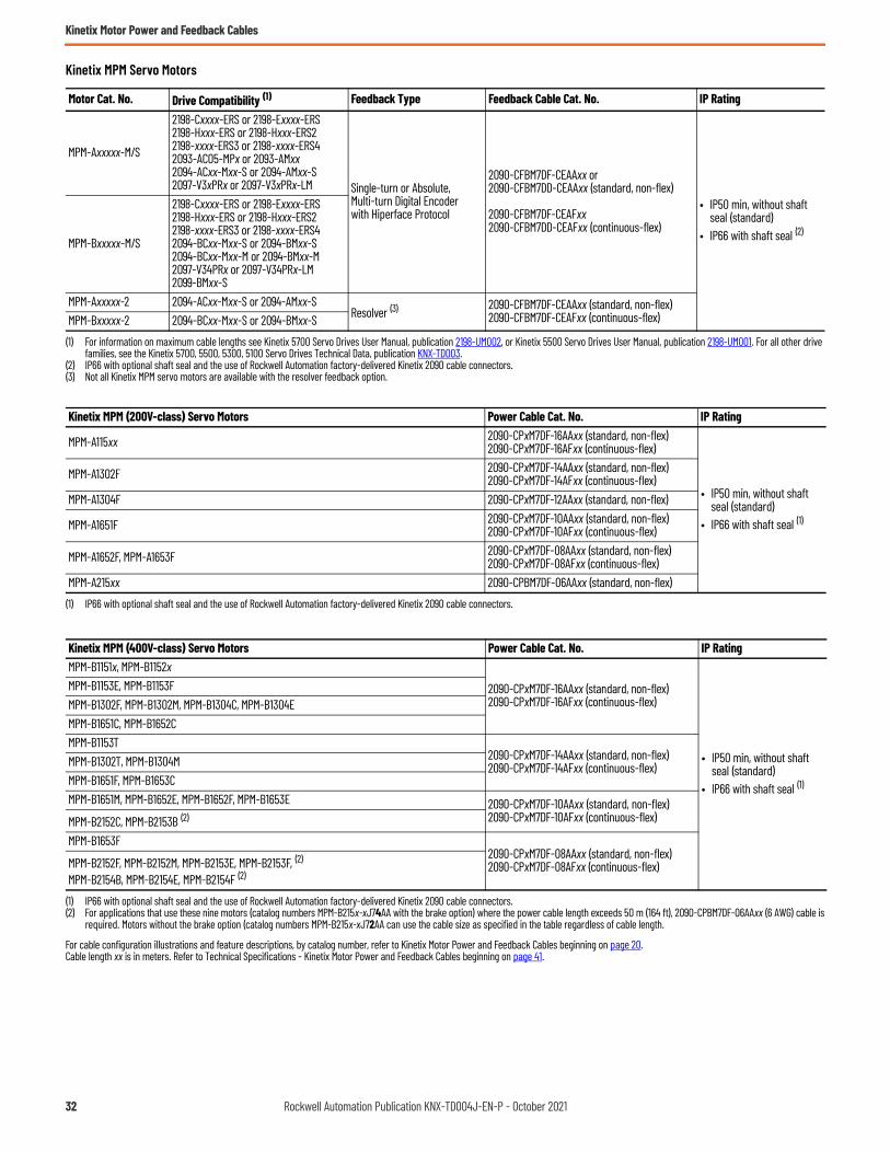
Kinetix Motor Power and Feedback Cables
Kinetix MPM Servo Motors
For cable configuration illustrations and feature descriptions, by catalog number, refer to Kinetix Motor Power and Feedback Cables beginning on page 20.Cable length xx is in meters. Refer to Technical Specifications - Kinetix Motor Power and Feedback Cables beginning on page 41.
Motor Cat. No. Drive Compatibility (1)
(1) For information on maximum cable lengths see Kinetix 5700 Servo Drives User Manual, publication 2198-UM002, or Kinetix 5500 Servo Drives User Manual, publication 2198-UM001. For all other drive families, see the Kinetix 5700, 5500, 5300, 5100 Servo Drives Technical Data, publication KNX-TD003.
Feedback Type Feedback Cable Cat. No. IP Rating
MPM-Axxxxx-M/S
2198-Cxxxx-ERS or 2198-Exxxx-ERS2198-Hxxx-ERS or 2198-Hxxx-ERS22198-xxxx-ERS3 or 2198-xxxx-ERS42093-AC05-MPx or 2093-AMxx2094-ACxx-Mxx-S or 2094-AMxx-S2097-V3xPRx or 2097-V3xPRx-LM Single-turn or Absolute,
Multi-turn Digital Encoder with Hiperface Protocol
2090-CFBM7DF-CEAAxx or2090-CFBM7DD-CEAAxx (standard, non-flex)
2090-CFBM7DF-CEAFxx 2090-CFBM7DD-CEAFxx (continuous-flex)
• IP50 min, without shaft seal (standard)
• IP66 with shaft seal (2)
(2) IP66 with optional shaft seal and the use of Rockwell Automation factory-delivered Kinetix 2090 cable connectors.
MPM-Bxxxxx-M/S
2198-Cxxxx-ERS or 2198-Exxxx-ERS2198-Hxxx-ERS or 2198-Hxxx-ERS22198-xxxx-ERS3 or 2198-xxxx-ERS42094-BCxx-Mxx-S or 2094-BMxx-S2094-BCxx-Mxx-M or 2094-BMxx-M2097-V34PRx or 2097-V34PRx-LM2099-BMxx-S
MPM-Axxxxx-2 2094-ACxx-Mxx-S or 2094-AMxx-SResolver (3)
(3) Not all Kinetix MPM servo motors are available with the resolver feedback option.
2090-CFBM7DF-CEAAxx (standard, non-flex)2090-CFBM7DF-CEAFxx (continuous-flex)MPM-Bxxxxx-2 2094-BCxx-Mxx-S or 2094-BMxx-S
Kinetix MPM (200V-class) Servo Motors Power Cable Cat. No. IP Rating
MPM-A115xx 2090-CPxM7DF-16AAxx (standard, non-flex)2090-CPxM7DF-16AFxx (continuous-flex)
• IP50 min, without shaft seal (standard)
• IP66 with shaft seal (1)
(1) IP66 with optional shaft seal and the use of Rockwell Automation factory-delivered Kinetix 2090 cable connectors.
MPM-A1302F 2090-CPxM7DF-14AAxx (standard, non-flex)2090-CPxM7DF-14AFxx (continuous-flex)
MPM-A1304F 2090-CPxM7DF-12AAxx (standard, non-flex)
MPM-A1651F 2090-CPxM7DF-10AAxx (standard, non-flex)2090-CPxM7DF-10AFxx (continuous-flex)
MPM-A1652F, MPM-A1653F 2090-CPxM7DF-08AAxx (standard, non-flex)2090-CPxM7DF-08AFxx (continuous-flex)
MPM-A215xx 2090-CPBM7DF-06AAxx (standard, non-flex)
Kinetix MPM (400V-class) Servo Motors Power Cable Cat. No. IP RatingMPM-B1151x, MPM-B1152x
2090-CPxM7DF-16AAxx (standard, non-flex)2090-CPxM7DF-16AFxx (continuous-flex)
• IP50 min, without shaft seal (standard)
• IP66 with shaft seal (1)
(1) IP66 with optional shaft seal and the use of Rockwell Automation factory-delivered Kinetix 2090 cable connectors.
MPM-B1153E, MPM-B1153FMPM-B1302F, MPM-B1302M, MPM-B1304C, MPM-B1304EMPM-B1651C, MPM-B1652CMPM-B1153T
2090-CPxM7DF-14AAxx (standard, non-flex)2090-CPxM7DF-14AFxx (continuous-flex)MPM-B1302T, MPM-B1304M
MPM-B1651F, MPM-B1653CMPM-B1651M, MPM-B1652E, MPM-B1652F, MPM-B1653E 2090-CPxM7DF-10AAxx (standard, non-flex)
2090-CPxM7DF-10AFxx (continuous-flex)MPM-B2152C, MPM-B2153B (2)
(2) For applications that use these nine motors (catalog numbers MPM-B215x-xJ74AA with the brake option) where the power cable length exceeds 50 m (164 ft), 2090-CPBM7DF-06AAxx (6 AWG) cable is required. Motors without the brake option (catalog numbers MPM-B215x-xJ72AA can use the cable size as specified in the table regardless of cable length.
MPM-B1653F2090-CPxM7DF-08AAxx (standard, non-flex)2090-CPxM7DF-08AFxx (continuous-flex)MPM-B2152F, MPM-B2152M, MPM-B2153E, MPM-B2153F, (2)
MPM-B2154B, MPM-B2154E, MPM-B2154F (2)
32 Rockwell Automation Publication KNX-TD004J-EN-P - October 2021

Kinetix Motor Power and Feedback Cables
Kinetix MPF Servo Motors
For cable configuration illustrations and feature descriptions, by catalog number, refer to Kinetix Motor Power and Feedback Cables beginning on page 20.Cable length xx is in meters. Refer to Technical Specifications - Kinetix Motor Power and Feedback Cables beginning on page 41.
Kinetix MPS Servo Motors
Motor Cat. No. Drive Compatibility (1)
(1) For information on maximum cable lengths see Kinetix 5700 Servo Drives User Manual, publication 2198-UM002, or Kinetix 5500 Servo Drives User Manual, publication 2198-UM001. For all other drive families, see the Kinetix 5700, 5500, 5300, 5100 Servo Drives Technical Data, publication KNX-TD003.
Feedback Type Feedback Cable Cat. No. IP Rating
MPF-Axxxx-M/S
2198-Cxxxx-ERS or 2198-Exxxx-ERS2198-Hxxx-ERS or 2198-Hxxx-ERS22198-xxxx-ERS3 or 2198-xxxx-ERS42093-AC05-MPx or 2093-AMxx 2094-ACxx-Mxx-S or 2094-AMxx-S2097-V3xPRx or 2097-V3xPRx-LM Single-turn or Absolute,
Multi-turn Digital Encoder with Hiperface Protocol
2090-CFBM7DF-CEAAxx or2090-CFBM7DD-CEAAxx (standard, non-flex)
2090-CFBM7DF-CEAFxx 2090-CFBM7DD-CEAFxx (continuous-flex)
IP66/IP67 with shaft seal (standard) (2)
(2) IP66/IP67 with shaft seal (standard) and the use of Rockwell Automation factory-delivered Kinetix 2090 cable connectors.
MPF-Bxxxx-M/S
2198-Cxxxx-ERS or 2198-Exxxx-ERS2198-Hxxx-ERS or 2198-Hxxx-ERS22198-Dxxx-ERS3 or 2198-Dxxx-ERS42094-BCxx-Mxx-S or 2094-BMxx-S2094-BCxx-Mxx-M or 2094-BMxx-M2097-V34PRx or 2097-V34PRx-LM
Kinetix MPF (200V-class) Servo Motors Power Cable Cat. No. IP RatingMPF-A310P, MPF-A320H, MPF-A320P, and MPF-A330P 2090-CPxM7DF-16AAxx (standard, non-flex)
2090-CPxM7DF-16AFxx (continuous-flex)IP66/IP67 with shaft seal (standard) (1)
(1) IP66/IP67 with shaft seal (standard) and the use of Rockwell Automation factory-delivered Kinetix 2090 cable connectors.
MPF-A430H
MPF-A430P, MPF-A4530K and MPF-A4540F 2090-CPxM7DF-14AAxx (standard, non-flex)2090-CPxM7DF-14AFxx (continuous-flex)
MPF-A540K 2090-CPxM7DF-08AAxx (standard, non-flex)2090-CPxM7DF-08AFxx (continuous-flex)
Kinetix MPF (400V-class) Servo Motors Power Cable Cat. No. IP RatingMPF-B310P, MPF-B320P, and MPF-B330P 2090-CPxM7DF-16AAxx (standard, non-flex)
2090-CPxM7DF-16AFxx (continuous-flex) IP66/IP67 with shaft seal (standard) (1)
(1) IP66/IP67 with shaft seal (standard) and the use of Rockwell Automation factory-delivered Kinetix 2090 cable connectors.
MPF-B430P, MPF-B4530K, and MPF-B4540F
MPF-B540K 2090-CPxM7DF-10AAxx (standard, non-flex)2090-CPxM7DF-10AFxx (continuous-flex)
Motor Cat. No. Drive Compatibility (1)
(1) For information on maximum cable lengths see Kinetix 5700 Servo Drives User Manual, publication 2198-UM002, or Kinetix 5500 Servo Drives User Manual, publication 2198-UM001. For all other drive families, see the Kinetix 5700, 5500, 5300, 5100 Servo Drives Technical Data, publication KNX-TD003.
Feedback Type Feedback Cable Cat. No. IP Rating (2)
(2) The cable connectors are rated IP66 and IP67 and are not designed to withstand high-pressure washdown or washdown with aggressive cleaning compounds. Position connectors away from direct exposure to cleaning processes, for example, within washdown-rated conduit or junction boxes.
MPS-Axxxx-M/S
2198-Cxxxx-ERS or 2198-Exxxx-ERS2198-Hxxx-ERS or 2198-Hxxx-ERS22198-Dxxx-ERS3 or 2198-Dxxx-ERS42093-AC05-MPx or 2093-AMxx 2094-ACxx-Mxx-S or 2094-AMxx-S2097-V3xPRx or 2097-V3xPRx-LM Single-turn or Absolute,
Multi-turn Digital Encoder with Hiperface Protocol
2090-CFBM7DF-CEAAxx or2090-CFBM7DD-CEAAxx (standard, non-flex)
2090-CFBM7DF-CEAFxx 2090-CFBM7DD-CEAFxx (continuous-flex)
• IP66/IP67 with shaft seal and slinger (standard) (3)
• IP69K with shaft seal and slinger (standard) (4)
(3) IP66/IP67 with shaft seal and slinger (standard) and the use of Rockwell Automation factory-delivered Kinetix 2090 cable connectors (includes on-motor cable connectors).(4) IP69K for 1200 psi motor washdown with shaft seal and slinger (standard). Does not include on-motor cable connectors.
MPS-Bxxxx-M/S
2198-Cxxxx-ERS or 2198-Exxxx-ERS2198-Hxxx-ERS or 2198-Hxxx-ERS22198-Dxxx-ERS3 or 2198-Dxxx-ERS42094-BCxx-Mxx-S or 2094-BMxx-S2094-BCxx-Mxx-M or 2094-BMxx-M2097-V34PRx or 2097-V34PRx-LM
Rockwell Automation Publication KNX-TD004J-EN-P - October 2021 33

Kinetix Motor Power and Feedback Cables
Kinetix MPS Servo Motors (continued)
For cable configuration illustrations and feature descriptions, by catalog number, refer to Kinetix Motor Power and Feedback Cables beginning on page 20.Cable length xx is in meters. Refer to Technical Specifications - Kinetix Motor Power and Feedback Cables beginning on page 41.
Kinetix RDB Servo Motors
For cable configuration illustrations and feature descriptions, by catalog number, refer to Kinetix Motor Power and Feedback Cables beginning on page 20.Cable length xx is in meters. Refer to Technical Specifications - Kinetix Motor Power and Feedback Cables beginning on page 41.
Kinetix MPS (200V-class) Servo Motors Power Cable Cat. No. IP Rating (1)
(1) The cable connectors are rated IP66 and IP67 and are not designed to withstand high-pressure washdown or washdown with aggressive cleaning compounds. Position connectors away from direct exposure to cleaning processes, for example, within washdown-rated conduit or junction boxes.
MPS-A330P2090-CPxM7DF-16AAxx (standard, non-flex)2090-CPxM7DF-16AFxx (continuous-flex)
• IP66/IP67 with shaft seal and slinger (standard) (2)
• IP69K with shaft seal and slinger (standard) (3)
(2) IP66/IP67 with shaft seal and slinger (standard) and the use of Rockwell Automation factory-delivered Kinetix 2090 cable connectors (includes on-motor cable connectors).(3) IP69K for 1200 psi motor washdown with shaft seal and slinger (standard). Does not include on-motor cable connectors.
MPS-A4540F
Kinetix MPS (400V-class) Servo Motors Power Cable Cat. No. IP Rating (1)
(1) The cable connectors are rated IP66 and IP67 and are not designed to withstand high-pressure washdown or washdown with aggressive cleaning compounds. Position connectors away from direct exposure to cleaning processes, for example, within washdown-rated conduit or junction boxes.
MPS-B330P 2090-CPxM7DF-16AAxx (standard, non-flex)2090-CPxM7DF-16AFxx (continuous-flex)
• IP66/IP67 with shaft seal and slinger (standard) (2)
• IP69K with shaft seal and slinger (standard) (3)
(2) IP66/IP67 with shaft seal and slinger (standard) and the use of Rockwell Automation factory-delivered Kinetix 2090 cable connectors (includes on-motor cable connectors).(3) IP69K for 1200 psi motor washdown with shaft seal and slinger (standard). Does not include on-motor cable connectors.
MPS-B4540F
MPS-B560F 2090-CPxM7DF-14AAxx (standard, non-flex)2090-CPxM7DF-14AFxx (continuous-flex)
Motor Cat. No. Drive Compatibility (1)
(1) For information on maximum cable lengths see Kinetix 5700 Servo Drives User Manual, publication 2198-UM002. For all other drive families, see the Kinetix 5700, 5500, 5300, 5100 Servo Drives Technical Data, publication KNX-TD003.
Feedback Type Feedback Cable Cat. No. IP Rating
RDB-Bxxxx-7/32198-xxxx-ERS3 or 2198-xxxx-ERS42094-BCxx-Mxx-S or 2094-BMxx-S2094-BCxx-Mxx-M or 2094-BMxx-M2099-BMxx-S
Single-turn or Absolute, Multi-turn High Resolution Encoder with EnDat Analog Protocol
2090-XXNFMF-Sxx (standard, non-flex) 2090-CFBM7DF-CDAFxx (continuous-flex) IP65 (2)
(2) IP65 with the use of Rockwell Automation factory-delivered Kinetix 2090 cable connectors.
Kinetix RDB (400V-class) Motors Power Cable Cat. No. IP RatingRDB-B21519, RDB-B21529 2090-CPWM7DF-16AAxx (standard, non-flex)
2090-CPWM7DF-16AFxx (continuous-flex)
IP65 (1)
(1) IP65 with the use of Rockwell Automation factory-delivered Kinetix 2090 cable connectors.
RDB-B29014, RDB-B29016, RDB-B29024 RDB-B2151C, RDB-B21539 2090-CPWM7DF-14AAxx (standard, non-flex)
2090-CPWM7DF-14AFxx (continuous-flex)RDB-B29019, RDB-B29034 RDB-B2152C
2090-CPWM7DF-12AAxx (standard, non-flex)RDB-B29026RDB-B2153C 2090-CPWM7DF-10AAxx (standard, non-flex)
2090-CPWM7DF-10AFxx (continuous-flex)RDB-B29036, RDB-B41014
RDB-B29029, RDB-B41016, RDB-B41024 2090-CPWM7DF-08AAxx (standard, non-flex)2090-CPWM7DF-08AFxx (continuous-flex)
RDB-B29039, RDB-B41018, RDB-B41026, RDB-B41035 2090-CPBM7DF-06AAxx (standard, non-flex)
34 Rockwell Automation Publication KNX-TD004J-EN-P - October 2021

Kinetix Motor Power and Feedback Cables
Kinetix HPK Servo Motors
For cable configuration illustrations and feature descriptions, by catalog number, refer to Kinetix Motor Power and Feedback Cables beginning on page 20.Cable length xx is in meters. Refer to Technical Specifications - Kinetix Motor Power and Feedback Cables beginning on page 41.
Kinetix MMA Main Motors
For cable configuration illustrations and feature descriptions, by catalog number, refer to Kinetix Motor Power and Feedback Cables beginning on page 20.Cable length xx is in meters. Refer to Technical Specifications - Kinetix Motor Power and Feedback Cables beginning on page 41.
Kinetix TL and TLY Servo Motors
Cat. No. Drive Compatibility (1)
(1) For information on maximum cable lengths see Kinetix 5700 Servo Drives User Manual, publication 2198-UM002. For all other drive families, see the Kinetix 5700, 5500, 5300, 5100 Servo Drives Technical Data, publication KNX-TD003.
Feedback Type Feedback Cable Cat. No. IP Rating
HPK-Bxxxxx-M/SHPK-Exxxxx-M/S
2198-Sxxx-ERS32198-Sxxx-ERS42099-BMxx-S
Absolute Single-turn or Multi-turn encoders with Hiperface protocol.
2090-CFBM7DF-CEAAxx or2090-CFBM7DD-CEAAxx (standard, non-flex)
2090-CFBM7DF-CEAFxx 2090-CFBM7DD-CEAFxx (continuous-flex)
IP65 (2)
(2) IP65 with the use of Rockwell Automation factory-delivered Kinetix 2090 feedback cable connector.
Kinetix HPK Servo Motors Power Cable Cat. No.All HPK-Bxxxx or HPK-Exxxx motors Customer Supplied
Cat. No. Drive Compatibility (1)
(1) For information on maximum cable lengths see Kinetix 5700 Servo Drives User Manual, publication 2198-UM002.
Feedback Type Feedback Cable Cat. No. IP Rating
MMA-B080, MMA-B100, MMA-B132, MMA-B160, MMA-B180, MMA-B225
2198-Dxxx-ERSx2198-Sxxx-ERS32198-Sxxx-ERS42099-BMxx-S
Absolute Single-turn or Multi-turn encoders with Hiperface or EnDat protocols
2090-CFBM7DF-CDAFxx (continuous-flex)(2)
(2) Kinetix 2090-CFBM7Dx-CExxxx style cables do not have the additional wire required for the PT1000 thermistor included in every Kinetix MMA motor
IP54 (3)
(3) Kinetix MMA motors come standard as IP54, but you can select IP55 as a configurable option. Both IP54/IP55 ratings require the use of Rockwell Automation factory-delivered Kinetix 2090 feedback cable connector.
Kinetix MMA Main Motors Power Cable Cat. No.All MMA-Bxxxx Customer Supplied(1)
(1) For information to help size cables for these large motors, see Kinetix MMA Asynchronous Motor Frequently Asked Questions for Good Installation Processes, Knowledgebase article for additional information.
Cat. No. Drive Compatibility (1)
(1) For information on maximum cable lengths see the Kinetix 5700, 5500, 5300, 5100 Servo Drives Technical Data, publication KNX-TD003.
Feedback Type Feedback Cable Cat. No. IP Rating
TLY-Axxxx-H
2198-Cxxxx-ERS or 2198-Exxxx-ERS2093-AC05-MPx or 2093-AMxx2094-ACxx-Mxx-S or 2094-AMxx-S2097-V3xPRx or 2097-V3xPRx-LM
Incremental
2090-CFBM6DF-CBAAxx (flying lead) or2090-CFBM6DD-CCAAxx (premolded connector)
• IP54 without shaft seal (standard) (2)
• IP65 with shaft seal (3)
• IP30 for on-motor cable connectors
(2) IP54 without shaft seal (standard) and with the use of Rockwell Automation factory-delivered Kinetix 2090 cable connectors (excludes on-motor cable connectors).(3) IP65 with optional shaft seal and with the use of Rockwell Automation factory-delivered Kinetix 2090 cable connectors (excludes on-motor cable connectors).
2071-Axx 2090-CFBM6DF-CBAAxx (flying lead)
TLY-Axxxx-B
2198-Cxxxx-ERS or 2198-Exxxx-ERS2093-AC05-MPx or 2093-AMxx2097-V3xPRx or 2097-V3xPRx-LM Absolute, Multi-turn Digital
Encoder with Tamagawa 17-bit Protocol
2090-CFBM6DF-CBAAxx (flying lead) or2090-CFBM6DD-CCAAxx (premolded connector)
2071-Axx 2090-CFBM6DF-CBAAxx (flying lead)
TL-Axxxx-B 2198-Cxxxx-ERS or 2198-Exxxx-ERS2071-Axx 2090-DANFCT-Sxx (4)
(4) For 2198-Cxxxx-ERS and 2198-Exxxx-ERS drives with high-resolution encoder applications, remove the drive-side connector and wire flying leads to the 2198-K5xCK-D15M connector kit and customer-supplied 3.6V lithium battery. For 2071-Axx drives, use when high-resolution absolute encoder feedback is not required. For high-resolution encoder applications, remove the drive-side connector and wire flying leads to the 2071-TBMF connector kit with customer-supplied 3.6V lithium battery.
Kinetix TL and TLY (200V-class) Servo Motors Power Cable Cat. No. IP RatingTLY-Axxxx-H 2090-CPBM6DF-16AAxx
(power and brake)2090-CPWM6DF-16AAxx(power without brake)
• IP54 without shaft seal (standard) (1)
• IP65 with shaft seal (2)
• IP30 for on-motor cable connectors
(1) IP54 without shaft seal (standard) and with the use of Rockwell Automation factory-delivered Kinetix 2090 cable connectors (excludes on-motor cable connectors).
TLY-Axxxx-B
TL-Axxxx-B 2090-DANPT-16Sxx
Rockwell Automation Publication KNX-TD004J-EN-P - October 2021 35

Kinetix Motor Power and Feedback Cables
For cable configuration illustrations and feature descriptions, by catalog number, refer to Kinetix Motor Power and Feedback Cables beginning on page 20.Cable length xx is in meters. Refer to Technical Specifications - Kinetix Motor Power and Feedback Cables beginning on page 41.For N-Series retrofit cable information, refer to the Kinetix Rotary Motion Technical Data, publication KNX-TD001.
(2) IP65 with optional shaft seal and with the use of Rockwell Automation factory-delivered Kinetix 2090 cable connectors (excludes on-motor cable connectors).
Kinetix (200V-class) Servo Motors Brake Cable Cat. No. IP Rating
TL-Axxxx-B motors 2090-DANBT-18Sxx
• IP54 without shaft seal (standard) (1)
• IP65 with shaft seal (2)
• IP30 for on-motor cable connectors
(1) IP54 without shaft seal (standard) and with the use of Rockwell Automation factory-delivered Kinetix 2090 cable connectors (excludes on-motor cable connectors).(2) IP65 with optional shaft seal and with the use of Rockwell Automation factory-delivered Kinetix 2090 cable connectors (excludes on-motor cable connectors).
IMPORTANT TL-Axxxx-B motors have rectangular plastic on-motor connectors and are intended for use with Kinetix 5100, Kinetix 5300, and Kinetix 3 servo drives. The TLY-Axxxx motors have circular plastic on-motor connectors and are intended for use with Kinetix 5100, Kinetix 5300, Kinetix 2000, Kinetix 6000, and Kinetix 300/350 (200V-class) servo drives.
36 Rockwell Automation Publication KNX-TD004J-EN-P - October 2021

Kinetix Motor Power and Feedback Cables
Kinetix MPAS Integrated Linear Stages
Kinetix MPAS Integrated Linear Stages (continued)
For cable configuration illustrations and feature descriptions, by catalog number, refer to Kinetix Motor Power and Feedback Cables beginning on page 20.Cable length xx is in meters. Refer to Technical Specifications - Kinetix Motor Power and Feedback Cables beginning on page 41.
Actuator Cat. No. Drive Compatibility (1)
(1) For information on maximum cable lengths see Kinetix 5700 Servo Drives User Manual, publication 2198-UM002, or Kinetix 5500 Servo Drives User Manual, publication 2198-UM001. For all other drive families, see the Kinetix 5700, 5500, 5300, 5100 Servo Drives Technical Data, publication KNX-TD003.
Feedback Type Feedback Cable Cat. No. IP Rating
MPAS-Axxxxx-VxxSxA (ballscrew)MPMA-A (ballscrew)
2198-Cxxxx-ERS2198-Hxxx-ERS or 2198-Hxxx-ERS22093-AC05-MPx or 2093-AMxx 2094-ACxx-Mxx-S or 2094-AMxx-S2097-V3xPRx or 2097-V34PRx-LM
Absolute, Multi-turn Digital Encoder with Hiperface Protocol
2090-CFBM7DF-CEAAxx or2090-CFBM7DD-CEAAxx (standard, non-flex)
2090-CFBM7DF-CEAFxx 2090-CFBM7DD-CEAFxx (continuous-flex)
IP30 rating with unique, long life strip seal system.
MPAS-Axxxxx-ALMx2CMPMA-A
2198-Cxxxx-ERS2093-AC05-MPx or 2093-AMxx 2094-ACxx-Mxx-S or 2094-AMxx-S2097-V3xPRx2071-Axx
Incremental Magnetic Linear Encoder
2090-XXNFMF-Sxx (standard, non-flex)2090-CFBM7DF-CDAFxx (continuous-flex)
MPAS-Bxxxxx-VxxSxA (ballscrew)MPMA-B (ballscrew)
2198-Cxxxx-ERS2198-Hxxx-ERS or 2198-Hxxx-ERS22198-Dxxx-ERS3 or 2198-Dxxx-ERS42094-BCxx-Mxx-S or 2094-BMxx-S2094-BCxx-Mxx-M or 2094-BMxx-M2097-V3xPRx or 2097-V34PRx-LM
Absolute, Multi-turn Digital Encoder with Hiperface Protocol
2090-CFBM7DF-CEAAxx or2090-CFBM7DD-CEAAxx (standard, non-flex)
2090-CFBM7DF-CEAFxx 2090-CFBM7DD-CEAFxx (continuous-flex)
MPAS-Bxxxxx-ALMx2CMPMA-B
2198-Cxxxx-ERS2198-Dxxx-ERS3 or 2198-Dxxx-ERS42094-BCxx-Mxx-S or 2094-BMxx-S2094-BCxx-Mxx-M or 2094-BMxx-M2097-V3xPRx
Incremental Magnetic Linear Encoder
2090-XXNFMF-Sxx (standard, non-flex)2090-CFBM7DF-CDAFxx (continuous-flex)
Kinetix MPAS (200V-class) Integrated Linear Stages Power Cable Cat. No. IP RatingMPAS-Axxxxx-VxxSxA (ballscrew) orMPMA-A
2090-CPxM7DF-16AAxx (standard, non-flex)2090-CPxM7DF-16AFxx (continuous-flex) IP30 rating with
unique, long life strip seal system.MPAS-Axxxxx-ALMx2C or
MPMA-A2090-CPWM7DF-16AAxx (standard, non-flex)2090-CPWM7DF-16AFxx (continuous-flex)
Kinetix MPAS (400V-class) Integrated Linear Stages Power Cable Cat. No. IP RatingMPAS-Bxxxxx-VxxSxA (ballscrew) orMPMA-B
2090-CPxM7DF-16AAxx (standard, non-flex)2090-CPxM7DF-16AFxx (continuous-flex) IP30 rating with
unique, long life strip seal system.MPAS-Bxxxxx-ALMx2C or
MPMA-B2090-CPWM7DF-16AAxx (standard, non-flex)2090-CPWM7DF-16AFxx (continuous-flex)
Rockwell Automation Publication KNX-TD004J-EN-P - October 2021 37
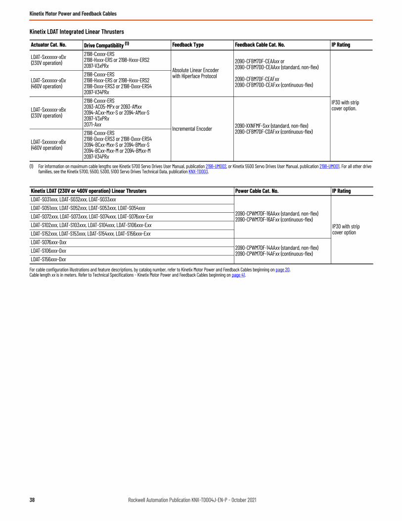
Kinetix Motor Power and Feedback Cables
Kinetix LDAT Integrated Linear Thrusters
For cable configuration illustrations and feature descriptions, by catalog number, refer to Kinetix Motor Power and Feedback Cables beginning on page 20.Cable length xx is in meters. Refer to Technical Specifications - Kinetix Motor Power and Feedback Cables beginning on page 41.
Actuator Cat. No. Drive Compatibility (1)
(1) For information on maximum cable lengths see Kinetix 5700 Servo Drives User Manual, publication 2198-UM002, or Kinetix 5500 Servo Drives User Manual, publication 2198-UM001. For all other drive families, see the Kinetix 5700, 5500, 5300, 5100 Servo Drives Technical Data, publication KNX-TD003.
Feedback Type Feedback Cable Cat. No. IP Rating
LDAT-Sxxxxxx-xDx(230V operation)
2198-Cxxxx-ERS2198-Hxxx-ERS or 2198-Hxxx-ERS22097-V3xPRx
Absolute Linear Encoder with Hiperface Protocol
2090-CFBM7DF-CEAAxx or2090-CFBM7DD-CEAAxx (standard, non-flex)
2090-CFBM7DF-CEAFxx 2090-CFBM7DD-CEAFxx (continuous-flex)
IP30 with strip cover option.
LDAT-Sxxxxxx-xDx(460V operation)
2198-Cxxxx-ERS2198-Hxxx-ERS or 2198-Hxxx-ERS22198-Dxxx-ERS3 or 2198-Dxxx-ERS42097-V34PRx
LDAT-Sxxxxxx-xBx(230V operation)
2198-Cxxxx-ERS2093-AC05-MPx or 2093-AMxx 2094-ACxx-Mxx-S or 2094-AMxx-S2097-V3xPRx2071-Axx
Incremental Encoder 2090-XXNFMF-Sxx (standard, non-flex)2090-CFBM7DF-CDAFxx (continuous-flex)
LDAT-Sxxxxxx-xBx(460V operation)
2198-Cxxxx-ERS2198-Dxxx-ERS3 or 2198-Dxxx-ERS42094-BCxx-Mxx-S or 2094-BMxx-S2094-BCxx-Mxx-M or 2094-BMxx-M2097-V34PRx
Kinetix LDAT (230V or 460V operation) Linear Thrusters Power Cable Cat. No. IP Rating LDAT-S031xxx, LDAT-S032xxx, LDAT-S033xxx
2090-CPWM7DF-16AAxx (standard, non-flex)2090-CPWM7DF-16AFxx (continuous-flex)
IP30 with strip cover option
LDAT-S051xxx, LDAT-S052xxx, LDAT-S053xxx, LDAT-S054xxxLDAT-S072xxx, LDAT-S073xxx, LDAT-S074xxx, LDAT-S076xxx-ExxLDAT-S102xxx, LDAT-S103xxx, LDAT-S104xxx, LDAT-S106xxx-ExxLDAT-S152xxx, LDAT-S153xxx, LDAT-S154xxx, LDAT-S156xxx-ExxLDAT-S076xxx-Dxx
2090-CPWM7DF-14AAxx (standard, non-flex)2090-CPWM7DF-14AFxx (continuous-flex)LDAT-S106xxx-Dxx
LDAT-S156xxx-Dxx
38 Rockwell Automation Publication KNX-TD004J-EN-P - October 2021

Kinetix Motor Power and Feedback Cables
Kinetix MPAR Electric Cylinders
Kinetix MPAI Heavy-duty Electric Cylinders
For cable configuration illustrations and feature descriptions, by catalog number, refer to Kinetix Motor Power and Feedback Cables beginning on page 20.Cable length xx is in meters. Refer to Technical Specifications - Kinetix Motor Power and Feedback Cables beginning on page 41.
Actuator Cat. No. Drive Compatibility (1)
(1) For information on maximum cable lengths see Kinetix 5700 Servo Drives User Manual, publication 2198-UM002, or Kinetix 5500 Servo Drives User Manual, publication 2198-UM001. For all other drive families, see the Kinetix 5700, 5500, 5300, 5100 Servo Drives Technical Data, publication KNX-TD003.
Feedback Type Feedback Cable Cat. No. IP Rating
MPAR-A1xxxxMPAR-A2xxxxMPAR-A3xxxx
2198-Cxxxx-ERS2198-Hxxx-ERS or 2198-Hxxx-ERS22093-AC05-MPx or 2093-AMxx 2094-ACxx-Mxx-S or 2094-AMxx-S2097-V3xPRx or 2097-V3xPRx-LM
Absolute, Multi-turn Encoder with Hiperface Protocol
2090-CFBM7DF-CEAAxx or2090-CFBM7DD-CEAAxx (standard, non-flex)
2090-CFBM7DF-CEAFxx or2090-CFBM7DD-CEAFxx (continuous-flex)
• IP40 (2)
• IP66 (3)
(2) IP40 applies to complete Kinetix MPAR unit, including rod-end seal and breather port.(3) IP66 (in static condition only) for electronic components and with the use of Rockwell Automation factory-delivered Kinetix 2090 cable connectors.
MPAR-B1xxxxMPAR-B2xxxxMPAR-B3xxxx
2198-Cxxxx-ERS2198-Hxxx-ERS or 2198-Hxxx-ERS22198-Dxxx-ERS3 or 2198-Dxxx-ERS42094-BCxx-Mxx-S or 2094-BMxx-S2094-BCxx-Mxx-M or 2094-BMxx-M2097-V34PRx or 2097-V34PRx-LM
Kinetix MPAR (200V-class) Electric Cylinders Power Cable Cat. No. IP Rating MPAR-A1xxxxMPAR-A2xxxxMPAR-A3xxxx
2090-CPxM7DF-16AAxx (standard, non-flex)2090-CPxM7DF-16AFxx (continuous-flex)
• IP40 (1)
• IP66 (2)
Kinetix MPAR (400V-class) Electric Cylinders Power Cable Cat. No. IP Rating MPAR-B1xxxxMPAR-B2xxxxMPAR-B3xxxx
2090-CPxM7DF-16AAxx (standard, non-flex)2090-CPxM7DF-16AFxx (continuous-flex)
• IP40 (1)
• IP66 (2)
(1) IP40 applies to complete Kinetix MPAR unit, including rod-end seal and breather port.(2) IP66 (in static condition only) for electronic components and with the use of Rockwell Automation factory-delivered Kinetix 2090 cable connectors.
Actuator Cat. No. Drive Compatibility (1)
(1) For information on maximum cable lengths see Kinetix 5700 Servo Drives User Manual, publication 2198-UM002, or Kinetix 5500 Servo Drives User Manual, publication 2198-UM001. For all other drive families, see the Kinetix 5700, 5500, 5300, 5100 Servo Drives Technical Data, publication KNX-TD003.
Feedback Type Feedback Cable Cat. No. IP Rating
MPAI-A2xxxxMPAI-A3xxxxMPAI-A4xxxxMPAI-A5xxxx
2198-Cxxxx-ERS2198-Hxxx-ERS or 2198-Hxxx-ERS22093-AC05-MPx or 2093-AMxx 2094-ACxx-Mxx-S or 2094-AMxx-S2097-V3xPRx or 2097-V3xPRx-LM
Absolute, Multi-turn Encoder with Hiperface Protocol
2090-CFBM7DF-CEAAxx or2090-CFBM7DD-CEAAxx (standard, non-flex)
2090-CFBM7DF-CEAFxx or2090-CFBM7DD-CEAFxx (continuous-flex)
IP66/IP67 (2)
(2) IP66/IP67 (in static condition only) and with the use of Rockwell Automation factory-delivered Kinetix 2090 cable connectors.
MPAI-B2xxxxMPAI-B3xxxxMPAI-B4xxxxMPAI-B5xxxx
2198-Cxxxx-ERS2198-Hxxx-ERS or 2198-Hxxx-ERS22198-Dxxx-ERS3 or 2198-Dxxx-ERS42094-BCxx-Mxx-S or 2094-BMxx-S2094-BCxx-Mxx-M or 2094-BMxx-M2097-V34PRx or 2097-V34PRx-LM
Kinetix MPAI (200V-class) Heavy-duty Electric Cylinders Power Cable Cat. No. IP Rating
MPAI-A2xxxx, MPAI-A3xxxx, MPAI-A4xxxx 2090-CPxM7DF-16AAxx (standard, non-flex)2090-CPxM7DF-16AFxx (continuous-flex)
IP66/IP67 (1)MPAI-A5xxxx 2090-CPxM7DF-14AAxx (standard, non-flex)
2090-CPxM7DF-14AFxx (continuous-flex)
Kinetix MPAI (400V-class) Heavy-duty Electric Cylinders Power Cable Cat. No. IP Rating
MPAI-B2xxxx, MPAI-B3xxxx, MPAI-B4xxxx, MPAI-B5xxxx 2090-CPxM7DF-16AAxx (standard, non-flex)2090-CPxM7DF-16AFxx (continuous-flex) IP66/IP67 (1)
(1) IP66/IP67 (in static condition only) and with the use of Rockwell Automation factory-delivered Kinetix 2090 cable connectors.
Rockwell Automation Publication KNX-TD004J-EN-P - October 2021 39
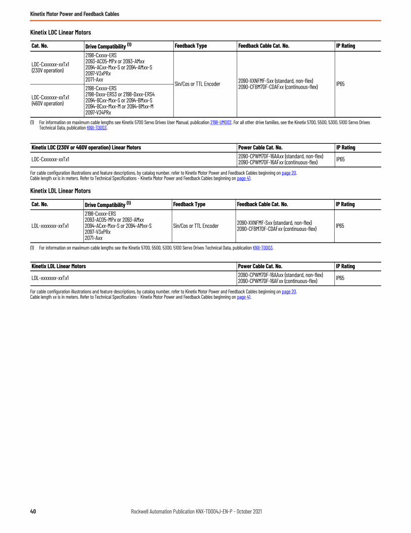
Kinetix Motor Power and Feedback Cables
Kinetix LDC Linear Motors
For cable configuration illustrations and feature descriptions, by catalog number, refer to Kinetix Motor Power and Feedback Cables beginning on page 20.Cable length xx is in meters. Refer to Technical Specifications - Kinetix Motor Power and Feedback Cables beginning on page 41.
Kinetix LDL Linear Motors
For cable configuration illustrations and feature descriptions, by catalog number, refer to Kinetix Motor Power and Feedback Cables beginning on page 20.Cable length xx is in meters. Refer to Technical Specifications - Kinetix Motor Power and Feedback Cables beginning on page 41.
Cat. No. Drive Compatibility (1)
(1) For information on maximum cable lengths see Kinetix 5700 Servo Drives User Manual, publication 2198-UM002. For all other drive families, see the Kinetix 5700, 5500, 5300, 5100 Servo Drives Technical Data, publication KNX-TD003.
Feedback Type Feedback Cable Cat. No. IP Rating
LDC-Cxxxxxx-xxTx1(230V operation)
2198-Cxxxx-ERS2093-AC05-MPx or 2093-AMxx 2094-ACxx-Mxx-S or 2094-AMxx-S2097-V3xPRx2071-Axx
Sin/Cos or TTL Encoder 2090-XXNFMF-Sxx (standard, non-flex)2090-CFBM7DF-CDAFxx (continuous-flex) IP65
LDC-Cxxxxxx-xxTx1(460V operation)
2198-Cxxxx-ERS2198-Dxxx-ERS3 or 2198-Dxxx-ERS42094-BCxx-Mxx-S or 2094-BMxx-S2094-BCxx-Mxx-M or 2094-BMxx-M2097-V34PRx
Kinetix LDC (230V or 460V operation) Linear Motors Power Cable Cat. No. IP Rating
LDC-Cxxxxxx-xxTx1 2090-CPWM7DF-16AAxx (standard, non-flex)2090-CPWM7DF-16AFxx (continuous-flex) IP65
Cat. No. Drive Compatibility (1)
(1) For information on maximum cable lengths see the Kinetix 5700, 5500, 5300, 5100 Servo Drives Technical Data, publication KNX-TD003.
Feedback Type Feedback Cable Cat. No. IP Rating
LDL-xxxxxxx-xxTx1
2198-Cxxxx-ERS2093-AC05-MPx or 2093-AMxx 2094-ACxx-Mxx-S or 2094-AMxx-S2097-V3xPRx2071-Axx
Sin/Cos or TTL Encoder 2090-XXNFMF-Sxx (standard, non-flex)2090-CFBM7DF-CDAFxx (continuous-flex) IP65
Kinetix LDL Linear Motors Power Cable Cat. No. IP Rating
LDL-xxxxxxx-xxTx1 2090-CPWM7DF-16AAxx (standard, non-flex)2090-CPWM7DF-16AFxx (continuous-flex) IP65
40 Rockwell Automation Publication KNX-TD004J-EN-P - October 2021

Kinetix Motor Power and Feedback Cables
Technical Specifications - Kinetix Motor Power and Feedback Cables
Power Cable Specifications
Brake Cable Specifications
IMPORTANT Maximum motor cable length depends on the feedback type and overall system design. The drive-system power supply, AC input-power type, and AC input voltage are among the configuration variables. For more information on maximum cable lengths see your servo drive user manual or the Kinetix 5700, 5500, 5300, 5100 Servo Drives Technical Data, publicationKNX-TD003.
Power Cables (1)Cat. No.
(1) 2090-CPxM4DF-xxAxxx and 2090-CPxM7DF-xxAxxx power cables are UL Listed, bulk cable, type TC-ER.
Cable Type/Jacket Color Description Wire Size
AWGWeight, approxkg/m (lb/ft)
Standard Cable Lengthsm (ft)
2090-XXNPMF-16Sxx Standard (non-flex) cable, Industrial TPE,Black
Four conductor, 600V, shielded cable for three-phase power with additional four conductors, 18 AWG, shielded, for motor brake and spares.
16 0.276 (0.186)
01 (3.2)02 (6.5)03 (9.8)04 (13.1)05 (16.4)
07 (22.9)09 (29.5)12 (39.4)15 (49.2)20 (65.6)
25 (82.0)30 (98.4)40 (131.2)60 (196.8)90 (295.3)
2090-XXNPMF-14Sxx 14 0.315 (0.212)
2090-CPBM7DF-16AAxx
Standard (non-flex) cable, Industrial TPE, Orange (DESINA, RAL 2003)
Four conductor, 600V, shielded cable for three-phase power with additional two conductors 18 AWG for motor brake.
16 0.212 (0.143)2090-CPBM7DF-14AAxx 14 0.261 (0.175)2090-CPBM7DF-12AAxx 12 0.349 (0.235)2090-CPBM7DF-10AAxx 10 0.492 (0.331)2090-CPBM7DF-08AAxx 8 0.708 (0.476)2090-CPBM7DF-06AAxx 6 1.038 (0.698)
2090-CPBM7DF-04AAxx (2)
(2) For this cable, the 01 and 02 m (3.2 and 6.5 ft) standard lengths do not apply.
Four conductor, 600V, shielded cable for three-phase power with additional two conductors 16 AWG for motor brake.
4 1.549 (1.041)
2090-CPBM7DF-02AAxx (2) 2 2.166 (1.455)2090-CPWM7DF-16AAxx
Four conductor, 600V, shielded cable for three-phase power.
16 0.136 (0.091)2090-CPWM7DF-14AAxx 14 0.185 (0.124)2090-CPWM7DF-12AAxx 12 0.248 (0.167)2090-CPWM7DF-10AAxx 10 0.418 (0.281)2090-CPWM7DF-08AAxx 8 0.644 (0.433)2090-CPWM6DF-16AAxx Standard (non-flex)
cable, Industrial TPE,Black
160.138 (0.093)
01 (3.2)02 (6.5)03 (9.8)04 (13.1)
05 (16.4)07 (22.9)09 (29.5)12 (39.4)
15 (49.2)20 (65.6)25 (82.0)30 (98.4)
2090-DANPT-16Sxx 162090-CPBM6DF-16AAxx
Four conductor, 600V, shielded cable for three-phase power with additional two conductors 18 AWG for motor brake.
16 0.180 (0.121)2090-CPBM4DF-16AFxx
Continuous-flex cable
Industrial TPE, Orange (DESINA, RAL 2003)
160.228 (0.153)
01 (3.2)02 (6.5)03 (9.8)04 (13.1)05 (16.4)07 (22.9)
09 (29.5)12 (39.4)15 (49.2)20 (65.6)25 (82.0)30 (98.4)
40 (131.2)50 (164.0)60 (196.8)75 (264.0)90 (295.3)
2090-CPBM7DF-16AFxx 162090-CPBM7DF-14AFxx 14 0.289 (0.194)2090-CPBM7DF-10AFxx 10 0.513 (0.345)2090-CPBM7DF-08AFxx 8 0.697 (0.468)2090-CPWM4DF-16AFxx
Four conductor, 600V, shielded cable for three-phase power.
160.154 (0.104)
2090-CPWM7DF-16AFxx 162090-CPWM7DF-14AFxx 14 0.196 (0.132)2090-CPWM7DF-10AFxx 10 0.452 (0.304)2090-CPWM7DF-08AFxx 8 0.666 (0.448)
Brake CablesCat. No.
Cable Type/Jacket Color Description Wire Size
AWGWeight, approxkg/m (lb/ft)
Standard Cable Lengthsm (ft)
2090-DANBT-18SxxStandard (non-flex) cable, Industrial TPE,Black
Two conductor, 600V, 18 AWG, shielded cable for motor brake. 18 0.070 (0.047)
01 (3.2)02 (6.5)03 (9.8)04 (13.1)
05 (16.4)07 (22.9)09 (29.5)12 (39.4)
15 (49.2)20 (65.6)25 (82.0)30 (98.4)
Rockwell Automation Publication KNX-TD004J-EN-P - October 2021 41

Kinetix Motor Power and Feedback Cables
Feedback Cable Specifications
Continuous-flex Extension Cable Specifications
Power and Feedback Transition Cable Specifications
Feedback Cables (1) (2)
Cat. No.
(1) 2090-CFBM7xx-CEAxxx feedback cables are UL Listed, bulk cable, type PLTC-ER.(2) 2090-CFBM4DF-CDAxxx and 2090-CFBM7xx-CDAxxx feedback cables are UL Listed, bulk cable, type CM.
Cable Type/Jacket Color Description Wire Size
AWGWeight, approxkg/m (lb/ft)
Standard Cable Lengthsm (ft)
2090-XXNFMF-SxxStandard (non-flex) cable, Industrial TPE,Black
Threaded DIN connector (motor end) to flying leads (drive end), 30V.
28 Feedback16 Power, 5V22 Power, 9V
0.120 (1.35) 01 (3.2)02 (6.5)03 (9.8)04 (13.1)05 (16.4)
07 (22.9)09 (29.5)12 (39.4)15 (49.2)20 (65.6)
25 (82.0)30 (98.4)40 (131.2)60 (196.8)90 (295.3)
2090-CFBM7DD-CEAAxx Standard (non-flex) cable, Industrial TPE,Green (DESINA, RAL 6018)
SpeedTec DIN connector (motor end) to premolded connector (drive end), 600V. 22 All
conductors 0.136 (0.092)2090-CFBM7DF-CEAAxx SpeedTec DIN connector (motor end) to
flying leads (drive end), 600V.
2090-UXNFM-Sxx (3)
(3) Use with 2090-KFBM4-CAAA (threaded) or 2090-KFBM7-CAAA (SpeedTec) DIN connector kit.
Standard (non-flex) cable, Industrial TPE,Black
Flying-leads (motor end) to premolded connector (drive end), 30V.
28 Feedback16 Power, 5V22 Power, 9V
0.120 (1.35)
01 (3.2)03 (9.8)09 (29.5)
15 (49.2)30 (98.4)
2090-CFBM6DF-CBAAxx Circular plastic connector (motor end) to flying leads (drive end), 300V.
28 Feedback16 Power, 5V22 BAT+ 01 (3.2)
02 (6.5)03 (9.8)04 (13.1)
05 (16.4)07 (22.9)09 (29.5)12 (39.4)
15 (49.2)20 (65.6)25 (82.0)30 (98.4)
2090-CFBM6DD-CCAAxx Circular plastic connector (motor end) to premolded connector (drive end), 300V.
28 Feedback16 Power, 5V
2090-DANFCT-Sxx Rectangular plastic connector (motor end) to premolded connector (drive end), 30V.
28 Feedback16 Power, 5V22 BAT+
0.130 (0.088)
2090-CFBM4DF-CDAFxxContinuous-flex cable Industrial TPE,Green (DESINA, RAL 6018)
Threaded DIN connector (motor end) to flying leads (drive end), 600V.
26 Feedback16 Power, 5V22 Power, 9V
0.177 (0.119) 01 (3.2)02 (6.5)03 (9.8)04 (13.1)05 (16.4)07 (22.9)
09 (29.5)12 (39.4)15 (49.2)20 (65.6)25 (82.0)30 (98.4)
40 (131.2)50 (164.0)60 (196.8)75 (264.0)90 (295.3)
2090-CFBM7DF-CDAFxx SpeedTec DIN connector (motor end) to flying leads (drive end), 600V.2090-CFBM7DF-CEAFxx
22 All conductors 0.143 (0.096)
2090-CFBM7DD-CEAFxx SpeedTec DIN connector (motor end) to premolded connector (drive end), 600V.
Extension Cable (1) (2)
Cat. No.
(1) 2090-CPBM7E7-xxAFxx extension power cables are UL Listed, bulk cable, type TC-ER.(2) 2090-CFBM7E7-CDAFxx extension feedback cables are UL Listed, bulk cable, type CM.
2090-CFBM7E7-CEAFxx extension feedback cables are UL Listed, bulk cable, type PLTC-ER.
Cable Type/Jacket Color Description Weight, approx
kg/m (lb/ft)Standard Cable Lengthsm (ft)
2090-CPBM7E7-16AFxxPower with brake Industrial TPE, Orange (DESINA, RAL 2003)
SpeedTec DIN connector plug on motor end to SpeedTec DIN receptacle for mating with Kinetix 2090 standard, non-flex power/brake cable, 600V.
0.228 (0.153)
01 (3.2)02 (6.5)03 (9.8)04 (13.1)
05 (16.4)07 (22.9)09 (29.5)12 (39.4)
15 (49.2)20 (65.6)25 (82.0)30 (98.4)
2090-CPBM7E7-14AFxx 0.289 (0.194)2090-CPBM7E7-10AFxx 0.513 (0.345)2090-CPBM7E7-08AFxx 0.697 (0.468)2090-CFBM7E7-CDAFxx Feedback
Industrial TPE,Green (DESINA, RAL 6018)
SpeedTec DIN connector plug on motor end to SpeedTec DIN receptacle for mating with Kinetix 2090 standard, non-flex feedback cable, 600V.
0.153 (0.103)
2090-CFBM7E7-CEAFxx 0.143 (0.096)
Transition CableCat. No.
Cable GaugeAWG
Cable Type/Jacket Color Description Standard Cable Lengths
mm (in.)2090-CPBM4E2-14TR 14 and 16
Power with brakeIndustrial TPE,Black
Threaded DIN connector on motor end to bayonet receptacle for mating with existing bayonet cable, 600V.
500 (19.7)
2090-CPBM4E2-10TR 102090-CPBM4E2-08TR 82090-CPBM4E2-04TR 4 and 62090-CPWM4E2-14TR 14 and 16
Power (only)Industrial TPE,Black
2090-CPWM4E2-10TR 102090-CPWM4E2-08TR 82090-CPWM4E2-04TR 4 and 6
2090-CFBM4E2-CATR N/AFeedbackIndustrial TPE,Black
Threaded DIN connector on motor end to bayonet receptacle for mating with existing bayonet cable, 300V.
42 Rockwell Automation Publication KNX-TD004J-EN-P - October 2021
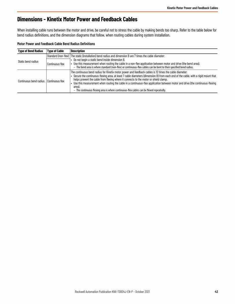
Kinetix Motor Power and Feedback Cables
Dimensions - Kinetix Motor Power and Feedback Cables
When installing cable runs between the motor and drive, be careful not to stress the cable by making bends too sharp. Refer to the table below for bend radius definitions, and the dimension diagrams that follow, when routing cables during system installation.
Motor Power and Feedback Cable Bend Radius Definitions
Type of Bend Radius Type of Cable Description
Static bend radius
Standard (non-flex) The static (installation) bend radius and dimension B are 7 times the cable diameter:• Do not begin a static bend inside dimension B.• Use this measurement when routing the cable in a non-flex application between motor and drive (the bend area).
– The bend area is where standard (non-flex) or continuous-flex cables can be bent to their specified bend radius.Continuous flex
Continuous bend radius Continuous flex
The continuous bend radius for Kinetix motor power and feedback cables is 12 times the cable diameter:• Secure the continuous-flexing area, at least 7 cable diameters (dimension B) from each end of the cable, with a rigid mount that
helps prevent the cable from flexing where it connects to the motor or shield clamp.• Use this measurement when routing the cable in a continuous-flex application between motor and drive (the continuous-flexing
area).– The continuous flexing area is where continuous-flex cables can be flexed repeatedly.
Rockwell Automation Publication KNX-TD004J-EN-P - October 2021 43

Kinetix Motor Power and Feedback Cables
Motor Power Cables
Power Cable Dimensions, Standard, Non-flex (SpeedTec DIN connector)
Power Cable Dimensions (standard, non-flex)
Power CableCat. No.
Amm (in.)
B (1)mm (in.)
(1) Dimension B is based on the cable diameter. Refer to Motor Power and Feedback Cable Bend Radius Definitions on page 43 for more information.
Cmm (in.)
Dmm (in.)
Emm (in.)
2090-CPBM7DF-16AAxx
147 (5.8)
81.2 (3.2)
28 (1.1)
11.6 (0.46)
150 (5.9)
2090-CPWM7DF-16AAxx 64.4 (2.5) 9.2 (0.36)2090-CPBM7DF-14AAxx 88.9 (3.5) 12.7 (0.50)2090-CPWM7DF-14AAxx 72.1 (2.8) 10.3 (0.40)2090-CPBM7DF-12AAxx
80 (3.15)100 (3.9) 14.3 (0.56)
2090-CPWM7DF-12AAxx 78.4 (3.1) 11.2 (0.44)2090-CPBM7DF-10AAxx
100 (3.9)
118 (4.6)
46 (1.8)
16.8 (0.66)
90 (3.5)
2090-CPWM7DF-10AAxx 107 (4.2) 15.3 (0.60)2090-CPBM7DF-08AAxx 141 (5.5) 20.1 (0.79)2090-CPWM7DF-08AAxx 131 (5.2) 18.7 (0.74)2090-CPBM7DF-06AAxx 170 (6.7) 24.3 (0.96)2090-CPBM7DF-04AAxx
150 (5.9)202 (7.9)
64 (2.5)28.8 (1.13)
2090-CPBM7DF-02AAxx 229 (9.0) 32.7 (1.29)
2090-CPBM7DF-xxAAxx16…12 AWG
2090-CPWM7DF-xxAAxx10…06 AWG
2090-CPBM7DF-xxAAxx04…02 AWG
A
EA B B
B B
E
A
DC
Bend Radius
Dimensions are in mm (in.)(reference only)
Typical End View
CableDiameterConnector
Diameter
BrownBlackBlueGreen/Yellow
Cable Shield(overall)
Cable Shield(for brake wires)
Cable Shield(overall)
Cable Shield(overall)
BrownBlackBlueGreen/Yellow
Bend Radius
Bend Area
Bend Area
Typical End View
BrownBlackBlueGreen/Yellow
Cable Shield(for brake wires)
44 Rockwell Automation Publication KNX-TD004J-EN-P - October 2021

Kinetix Motor Power and Feedback Cables
Power Cable Dimensions, Continuous-flex (SpeedTec DIN connector)
Power Cable Dimensions (continuous-flex rated)
Power CableCat. No.
Amm (in.)
B (1)mm (in.)
(1) Dimension B and Continuous Bend Radius are based on the cable diameter. Refer to Motor Power and Feedback Cable Bend Radius Definitions on page 43 for more information.
Continuous Bend Radius (1)
mm (in.)
Cmm (in.)
Dmm (in.)
Emm (in.)
2090-CPBM7DF-16AFxx
147 (5.8)
87.5 (3.4) 150 (5.9)
28 (1.1)
12.5 (0.49)
150 (5.9)2090-CPWM7DF-16AFxx 67.9 (2.7) 116 (4.6) 9.7 (0.38)2090-CPBM7DF-14AFxx 95.9 (3.8) 164 (6.5) 13.7 (0.54)2090-CPWM7DF-14AFxx 72.8 (2.9) 125 (4.9) 10.4 (0.41)2090-CPBM7DF-10AFxx
100 (3.9)
125 (4.9) 214 (8.4)
46 (1.8)
17.8 (0.70)
90 (3.5)2090-CPWM7DF-10AFxx 110 (4.3) 188 (7.4) 15.7 (0.62)2090-CPBM7DF-08AFxx 144 (5.7) 247 (9.7) 20.6 (0.81)2090-CPWM7DF-08AFxx 141 (5.5) 242 (9.5) 20.2 (0.79)
2090-CPBM7DF-16AFxx2090-CPBM7DF-14AFxx
D
2090-CPWM7DF-10AFxx2090-CPWM7DF-08AFxx
A B B
C
Bend Radius
Dimensions are in mm (in.)(reference only)
Typical End View
CableDiameterConnector
Diameter
BrownBlackBlueGreen/Yellow
Cable Shield(overall)
Cable Shield(for brake wires)
Cable Shield(overall)
Bend Area or Continuous Flexing Area
BrownBlackBlueGreen/Yellow
Rockwell Automation Publication KNX-TD004J-EN-P - October 2021 45

Kinetix Motor Power and Feedback Cables
Power Cable Dimensions (threaded DIN connector)
Power Cable Dimensions (standard, non-flex)
Power Cable Dimensions (continuous-flex rated)
Power CableCat. No.
Amm (in.)
B (1)mm (in.)
(1) Dimension B is based on the cable diameter. Refer to Motor Power and Feedback Cable Bend Radius Definitions on page 43 for more information.
Cmm (in.)
Dmm (in.)
Emm (in.)
2090-XXNPMF-16Sxx75 (2.9)
98.0 (3.8)28.0 (1.1)
14.0 (0.55) 150 (5.9) 2090-XXNPMF-14Sxx 105 (4.1) 15.0 (0.59)
90.0 (3.5) 2090-XXNPMF-10Sxx 96 (3.8) 133 (5.2) 46.0 (1.8) 19.0 (0.75)
Power CableCat. No.
Amm (in.)
B (1)mm (in.)
(1) Dimension B and Continuous Bend Radius are based on the cable diameter. Refer to Motor Power and Feedback Cable Bend Radius Definitions on page 43 for more information.
ContinuousBend Radius (1)mm (in.)
Cmm (in.)
Dmm (in.)
Emm (in.)
2090-CPBM4DF-16AFxx75 (2.9)
87.5 (3.4) 150 (5.9)28.0 (1.1)
12.5 (0.49)150 (5.9)
2090-CPWM4DF-16AFxx 67.9 (2.7) 116 (4.6) 9.7 (0.38)
BR+BR-
2090-XXNPMF-xxSxx
2090-CPBM4DF-xxAFxx
2090-CPWM4DF-xxAFxx
E
A B BE
EC
D
A B B
Cable Shield(overall)
Bend Radius
BrownBlackBlueGreen/Yellow
Cable Shield(for brake wires)
Dimensions are in mm (in.)(reference only)
CableDiameterConnector
Diameter
Typical End View
BrownBlackBlueGreen/Yellow
BrownBlackBlueGreen/Yellow
Cable Shield(overall)
Cable Shield(for brake wires)
Cable Shield(overall)
Bend Area orContinuous Flexing Area
Bend Radius
Bend Area
46 Rockwell Automation Publication KNX-TD004J-EN-P - October 2021
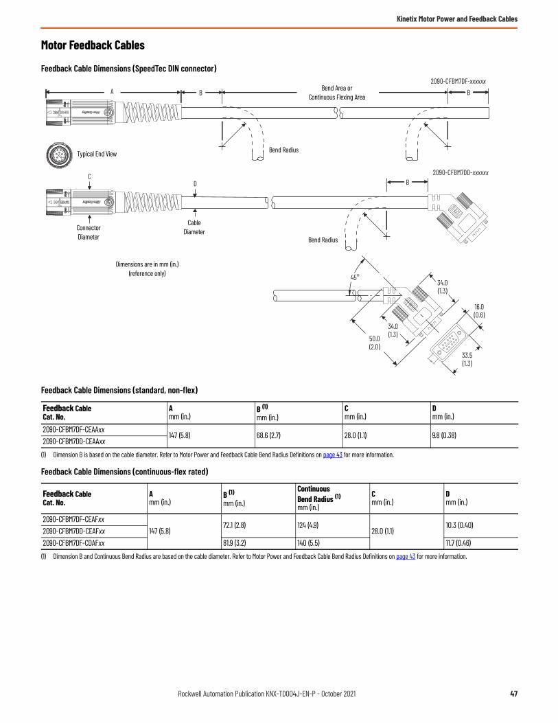
Kinetix Motor Power and Feedback Cables
Motor Feedback Cables
Feedback Cable Dimensions (SpeedTec DIN connector)
Feedback Cable Dimensions (standard, non-flex)
Feedback Cable Dimensions (continuous-flex rated)
Feedback CableCat. No.
Amm (in.)
B (1)
mm (in.)
(1) Dimension B is based on the cable diameter. Refer to Motor Power and Feedback Cable Bend Radius Definitions on page 43 for more information.
Cmm (in.)
Dmm (in.)
2090-CFBM7DF-CEAAxx147 (5.8) 68.6 (2.7) 28.0 (1.1) 9.8 (0.38)
2090-CFBM7DD-CEAAxx
Feedback CableCat. No.
Amm (in.)
B (1)mm (in.)
(1) Dimension B and Continuous Bend Radius are based on the cable diameter. Refer to Motor Power and Feedback Cable Bend Radius Definitions on page 43 for more information.
ContinuousBend Radius (1)mm (in.)
Cmm (in.)
Dmm (in.)
2090-CFBM7DF-CEAFxx147 (5.8)
72.1 (2.8) 124 (4.9)28.0 (1.1)
10.3 (0.40)2090-CFBM7DD-CEAFxx2090-CFBM7DF-CDAFxx 81.9 (3.2) 140 (5.5) 11.7 (0.46)
DC
A B B
50.0(2.0)
16.0(0.6)
33.5(1.3)
34.0(1.3)
34.0(1.3)
45°
B
2090-CFBM7DF-xxxxxx
2090-CFBM7DD-xxxxxx
ConnectorDiameter
CableDiameter
Bend Radius
Dimensions are in mm (in.)(reference only)
Bend Area orContinuous Flexing Area
Typical End View
Bend Radius
Rockwell Automation Publication KNX-TD004J-EN-P - October 2021 47

Kinetix Motor Power and Feedback Cables
Feedback Cable Dimensions (threaded DIN connector)
Feedback Cable Dimensions (standard, non-flex)
Feedback Cable Dimensions (continuous-flex rated)
Feedback Cable Dimensions (catalog number 2090-UXNFM-Sxx)
Feedback CableCat. No.
Amm (in.)
B (1)mm (in.)
(1) Dimension B is based on the cable diameter. Refer to Motor Power and Feedback Cable Bend Radius Definitions on page 43 for more information.
C mm (in.)
Dmm (in.)
2090-XXNFMF-Sxx 57.0 (2.2) 70 (2.7) 26.0 (1.0) 10.0 (0.40)
Feedback CableCat. No.
Amm (in.)
B (1)
mm (in.)
(1) Dimension B and Continuous Bend Radius are based on the cable diameter. Refer to Motor Power and Feedback Cable Bend Radius Definitions on page 43 for more information.
ContinuousBend Radius (1)mm (in.)
Cmm (in.)
Dmm (in.)
2090-CFBM4DF-CDAFxx 57.0 (2.2) 81.9 (3.2) 140 (5.5) 26.0 (1.0) 11.7 (0.46)
DC
A
2090-XXNFMF-Sxx2090-CFBM4DF-CDAFxx
B B
ConnectorDiameter
CableDiameter
Bend Radius
Dimensions are in mm (in.)(reference only)
Bend Area orContinuous Flexing Area
Bend Radius
9.6(0.38)
34.0(1.3)
50.0(2.0)
33.5(1.3)
16.0(0.6)
67.2(2.6)
67.2(2.6)
45°
CableDiameter
Dimensions are in mm (in.)(reference only)
Static Bend Radius = 67.2 (2.6)
48 Rockwell Automation Publication KNX-TD004J-EN-P - October 2021

Kinetix Motor Power and Feedback Cables
Continuous-flex Extension Cables
Power Cable Dimensions (SpeedTec DIN)
Power Cable Dimensions (continuous-flex rated)
Feedback Cable Dimensions (SpeedTec DIN)
Feedback Cable Dimensions (continuous-flex rated)
Power CableCat. No.
Amm (in.)
B (1)mm (in.)
(1) Dimension B and Continuous Bend Radius are based on the cable diameter. Refer to Motor Power and Feedback Cable Bend Radius Definitions on page 43 for more information.
ContinuousBend Radius (1)mm (in.)
Cmm (in.)
Dmm (in.)
2090-CPBM7E7-16AFxx147 (5.8)
87.5 (3.4) 150 (5.9)28.0 (1.1)
12.5 (0.49)2090-CPBM7E7-14AFxx 95.9 (3.8) 164 (6.4) 13.7 (0.54)2090-CPBM7E7-10AFxx
97 (3.8)125 (4.9) 214 (8.4)
46.0 (1.8)17.8 (0.70)
2090-CPBM7E7-08AFxx 144 (5.7) 247 (9.7) 20.6 (0.81)
Feedback CableCat. No.
Amm (in.)
B (1)mm (in.)
(1) Dimension B and Continuous Bend Radius are based on the cable diameter. Refer to Motor Power and Feedback Cable Bend Radius Definitions on page 43 for more information.
ContinuousBend Radius (1)
mm (in.)
Cmm (in.)
Dmm (in.)
2090-CFBM7E7-CEAFxx147 (5.8)
72.1 (2.8) 124 (4.9)28.0 (1.1)
10.3 (0.40)2090-CFBM7E7-CDAFxx 81.9 (3.2) 140 (5.5) 11.7 (0.46)
2090-CPBM7E7-16AFxx2090-CPBM7E7-14AFxx
2090-CPBM7E7-10AFxx2090-CPBM7E7-08AFxx
A B B A
DC
A B B A
Bend Radius
Dimensions are in mm (in.)(reference only)
CableDiameterConnector
Diameter
Bend Area orContinuous Flexing Area
Bend Radius Bend Radius
Bend Area orContinuous Flexing Area
D
2090-CFBM7E7-CDAFxx2090-CFBM7E7-CEAFxx
CA B B A
Bend Radius
Dimensions are in mm (in.)(reference only)
CableDiameterConnector
Diameter
Bend Area orContinuous Flexing Area
Bend Radius
Rockwell Automation Publication KNX-TD004J-EN-P - October 2021 49

Kinetix Motor Power and Feedback Cables
Transition Cables
Power Cable Dimensions
Power Cable Dimensions (standard, non-flex)
Feedback Cable Dimensions (catalog number 2090-CFBM4E2-CATR)
Power CableCat. No.
Amm (in.)
B (1)mm (in.)
(1) Dimension B is based on the cable diameter. Refer to Motor Power and Feedback Cable Bend Radius Definitions on page 43 for more information.
Cmm (in.)
Dmm (in.)
Emm (in.)
Fmm (in.)
2090-CPBM4E2-14TR80.0 (3.15)
104 (4.09)28.0 (1.10)
14.8 (0.58)31.0 (1.22)
90 (3.54)2090-CPWM4E2-14TR 72.8 (2.87) 10.4 (0.41)2090-CPBM4E2-10TR 80.0 (3.15) 129 (5.08)
46.0 (1.81)
18.4 (0.74) 46.0 (1.81)2090-CPWM4E2-10TR 95.0 (3.74) 102 (4.02) 14.5 (0.57) 31.0 (1.22)2090-CPBM4E2-08TR 98.7 (3.89) 144 (5.67) 20.5 (0.81)
46.0 (1.81) 146 (5.75)2090-CPWM4E2-08TR 95.0 (3.74) 132 (5.20) 18.9 (0.74)2090-CPBM4E2-04TR
147 (5.77) 201 (7.91) 64.0 (2.5) 28.7 (1.13)64.0 (2.52) 131 (5.17)
2090-CPWM4E2-04TR 63.7 (2.51) 132 (5.20)
500 (19.7)
AC
E
D
500 (19.7)
A
E
C
24(0.94)
D
F
E
F
8.10 (0.32) 66.72(2.63)
B B
B B
Bend Radius
Dimensions are in mm (in.)(reference only)
CableDiameter
ConnectorDiameter
ConnectorDiameter
2090-CPBM4E2-xxTR
2090-CPWM4E2-xxTR
Bend Radius
Bend Radius
Bend Area
Bend Area
500 (19.7)25.8(1.0)
9.6(0.38)
58(2.3)
90(3.5)
31(1.2)
67.2(2.6)
67.2(2.6)
Static Bend Radius = 67.2 (2.6)
Dimensions are in mm (in.)(reference only)Cable
Diameter
ConnectorDiameter
Bend Area
50 Rockwell Automation Publication KNX-TD004J-EN-P - October 2021
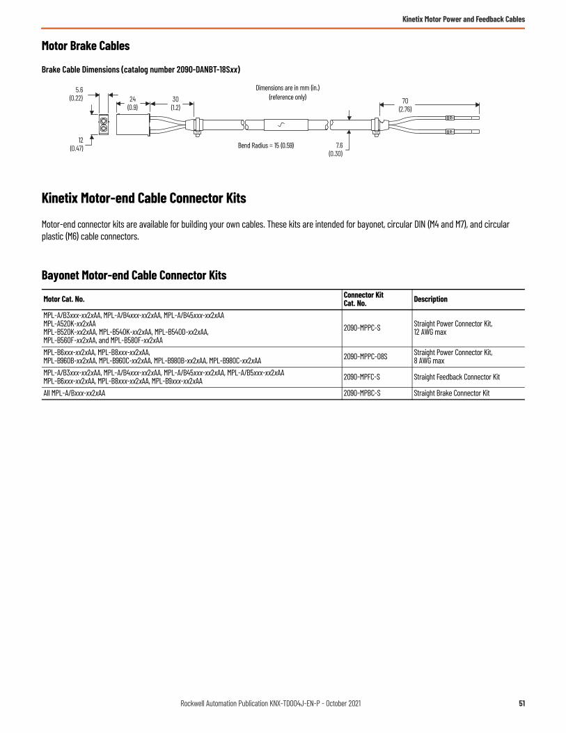
Kinetix Motor Power and Feedback Cables
Motor Brake Cables
Brake Cable Dimensions (catalog number 2090-DANBT-18Sxx)
Kinetix Motor-end Cable Connector Kits
Motor-end connector kits are available for building your own cables. These kits are intended for bayonet, circular DIN (M4 and M7), and circular plastic (M6) cable connectors.
Bayonet Motor-end Cable Connector Kits
Motor Cat. No. Connector Kit Cat. No. Description
MPL-A/B3xxx-xx2xAA, MPL-A/B4xxx-xx2xAA, MPL-A/B45xxx-xx2xAAMPL-A520K-xx2xAAMPL-B520K-xx2xAA, MPL-B540K-xx2xAA, MPL-B540D-xx2xAA, MPL-B560F-xx2xAA, and MPL-B580F-xx2xAA
2090-MPPC-S Straight Power Connector Kit, 12 AWG max
MPL-B6xxx-xx2xAA, MPL-B8xxx-xx2xAA, MPL-B960B-xx2xAA, MPL-B960C-xx2xAA, MPL-B980B-xx2xAA, MPL-B980C-xx2xAA 2090-MPPC-08S Straight Power Connector Kit,
8 AWG maxMPL-A/B3xxx-xx2xAA, MPL-A/B4xxx-xx2xAA, MPL-A/B45xxx-xx2xAA, MPL-A/B5xxx-xx2xAAMPL-B6xxx-xx2xAA, MPL-B8xxx-xx2xAA, MPL-B9xxx-xx2xAA 2090-MPFC-S Straight Feedback Connector Kit
All MPL-A/Bxxx-xx2xAA 2090-MPBC-S Straight Brake Connector Kit
12(0.47)
24(0.9)
5.6(0.22)
7.6(0.30)
70(2.76)
30(1.2)
Bend Radius = 15 (0.59)
Dimensions are in mm (in.)(reference only)
Rockwell Automation Publication KNX-TD004J-EN-P - October 2021 51

Kinetix Motor Power and Feedback Cables
Circular DIN Motor-end Cable Connector Kits
Feedback Cable Connector Kits
Power Cable Connector Kits
Motor-end Connector Kit Cross-reference Tables
The tables beginning on page 53 provide a cross-reference for the circular DIN (M4 and M7) connector kits above to the compatible motor series catalog number. Also provided are the bulkhead adapters for securing the cables as they pass through the cabinet and crimping tools required for properly attaching the power wires to sockets and pins. See Kinetix 2090 Circular-DIN Connector Kits, Flange Kits, and Crimp Tools, publication 2090-IN042, for more information.
Connector kits and crimping tools are also available for circular plastic (M6) connectors. Refer to page 54 for the compatible motor series and crimp tool catalog numbers.
M23 Cable PlugConnector Kits
M23 Cable ExtensionConnector Kits
Connector pins and sockets in these kits are soldered.
2090-KFBM4-CAAA2090-KFBM7-CAAA
Motor-end Connector Kits
2090-KFBE7-CAAAMotor-end Connector Kits
M23 or M40 Cable PlugConnector Kits
Connector pins and sockets in these kits are crimped.
M23 or M40 Cable ExtensionConnector Kits
2090-KPBM4-12AA2090-KPBM4-06AA2090-KPBM7-12AA2090-KPBM7-06AA
Motor-end Connector Kits
2090-KPBE7-12AA2090-KPBE7-06AA
Motor-end Connector Kits
52 Rockwell Automation Publication KNX-TD004J-EN-P - October 2021

Kinetix Motor Power and Feedback Cables
Power Cable Connector Kits (SpeedTec DIN)
Power Cable Connector Kits (threaded DIN)
Connector Kit Cat. No. Description Crimp Tool
Cat. No.Bulkhead AdapterCat. No. Motor Series
2090-KPBM7-12AAMotor-end cable connectorSpeedTec plug, M23 connector16, 14, and 12 AWG motor power18 AWG motor brake
2090-TCR47-M23 2090-KPB47-12CF
MPL-A/B15xxx-V/Ex7xAA, MPL-A/B2xxx-V/Ex7xAAMPL-A/B3xx, MPL-A/B4xx, MPL-A/B45xx, MPL-B520, MPL-B540, MPL-B560MPM-A/B115xx, MPM-A/B130xx, MPM-B1651C, MPM-B1651F, MPM-B1652C, MPM-B1653CMPF-A/B3xxx-S/Mx7xAA, MPF-A/B4xxx-S/Mx7xAA, MPF-A/B45xxx-S/Mx7xAAMPS-A/B3xx, MPS-A/B45xx, MPS-B5xx (SpeedTec motor connectors)RDB-B130xx, RDB-B165xx, RDB-B21519, RDB-B2151C, RDB-B21529, RDB-B2152C, RDB-B21539, RDB-B2901x, RDB-B29024, RDB-B29026, RDB-B29034
2090-KPBM7-06AAMotor-end cable connectorSpeedTec plug, M40 connector10, 8, and 6 AWG motor power18 AWG motor brake
2090-TCR47-M40 (power pins)
2090-TCR47-M23 (brake pins)
2090-KPB47-06CF
MPL-A5xx, MPL-B580, MPL-B6xx, MPL-B860, MPL-B880C, MPL-B960B, MPL-B980BMPM-A1651F, MPM-B1651M, MPM-B1652E, MPM-A/B1652F, MPM-B1653E, MPM-A/B1653F, MPM-A/B215xxMPF-A/B5xxx-S/Mx7xAARDB-B2151F, RDB-B2152F, RDB-B2153C, RDB-B2153E, RDB-B29029, RDB-B29036, RDB-B410xx
2090-KPBE7-12AAExtension cable connectorSpeedTec plug, M23 connector16, 14, and 12 AWG motor power18 AWG motor brake
2090-TCR47-M23 2090-KPB47-12CF
MPL-A/B3xx, MPL-A/B4xx, MPL-A/B45xx, MPL-B520, MPL-B540, MPL-B560MPM-A/B115xx, MPM-A/B130xx, MPM-B1651C, MPM-B1651F, MPM-B1652C, MPM-B1653CMPF-A/B3xxx-S/Mx7xAA, MPF-A/B4xxx-S/Mx7xAA, MPF-A/B45xxx-S/Mx7xAARDB-B130xx, RDB-B165xx, RDB-B21519, RDB-B2151C, RDB-B21529, RDB-B2152C, RDB-B21539, RDB-B2901x, RDB-B29024, RDB-B29026, RDB-B29034
2090-KPBE7-06AAExtension cable connectorSpeedTec plug, M40 connector10, 8, and 6 AWG motor power18 AWG motor brake
2090-TCR47-M40(power pins)
2090-TCR47-M23(brake pins)
2090-KPB47-06CF
MPL-A5xx, MPL-B580, MPL-B6xx, MPL-B860, MPL-B880C, MPL-B960B, MPL-B980BMPM-A1651F, MPM-B1651M, MPM-B1652E, MPM-A/B1652F, MPM-B1653E, MPM-A/B1653F, MPM-A/B215xxMPF-A/B5xxx-S/Mx7xAARDB-B2151F, RDB-B2152F, RDB-B2153C, RDB-B2153E, RDB-B29029, RDB-B29036, RDB-B410xx
Connector Kit Cat. No. Description Crimp Tool
Cat. No.Bulkhead AdapterCat. No. Motor Series
2090-KPBM4-12AAMotor-end cable connectorThreaded plug, M23 connector16, 14, and 12 AWG motor power18 AWG motor brake
2090-TCR47-M23 2090-KPB47-12CF
MPL-A/B15xxx-V/Ex4xAA, MPL-A/B2xxx-V/Ex4xAAMPF-A/B3xxx-S/Mx4xAA, MPF-A/B4xxx-S/Mx4xAA, MPF-A/B45xxx-S/Mx4xAA, MPF-A/B5xxx-S/Mx4xAAMPS-A/B3xx, MPS-A/B45xx, MPS-B5xx (threaded motor connectors)
2090-KPBM4-06AA
Motor-end cable connectorThreaded plug, M40 connector10, 8, and 6 AWG motor power18 AWG motor brake
2090-TCR47-M40 (power pins)
2090-TCR47-M23 (brake pins)
2090-KPB47-06CF MPF-A/B5xxx-S/Mx4xAA
Rockwell Automation Publication KNX-TD004J-EN-P - October 2021 53

Kinetix Motor Power and Feedback Cables
Feedback Cable Connector Kits (circular DIN)
Power and Feedback Cable Connector Kits (circular plastic)
Connector Kit Cat. No. Description Crimp Tool
Cat. No.Bulkhead AdapterCat. No.
Motor Series
2090-KFBM7-CAAA Motor-end cable connectorSpeedTec plug, M23 connector
N/A (soldered contacts)
2090-KFB47-CF
MPL-A/B15xxx-V/Ex7xAA or MPL-A/B2xxx-V/Ex7xAAMPL-A/B3xx, MPL-A/B4xx, MPL-A/B45xx, MPL-A/B5xxMPL-B6xx, MPL-B8xx, MPL-B9xxMPM-A/B115xx, MPM-A/B130xx, MPM-A/B165xx, MPM-A/B215xxMPF-A/B3xxx-S/Mx7xAA, MPF-A/B4xxx-S/Mx7xAA, MPF-A/B45xxx-S/Mx7xAA, MPF-A/B5xxx-S/Mx7xAAMPS-A/B3xx, MPS-A/B45xx, MPS-A/B5xx (SpeedTec motor connectors)RDB-B130xx, RDB-B165xx, RDB-B215xx, RDB-B290xx, RDB-B410xx
2090-KFBE7-CAAA Extension cable connectorSpeedTec plug, M23 connector
MPL-A/B3xx, MPL-A/B4xx, MPL-A/B45xx, MPL-A/B5xx, MPL-B6xx, MPL-B8xx, MPL-B9xxMPM-A/B115xx, MPM-A/B130xx, MPM-A/B165xx, MPM-A/B215xxMPF-A/B3xxx-S/Mx7xAA, MPF-A/B4xxx-S/Mx7xAA, MPF-A/B45xxx-S/Mx7xAA, MPF-A/B5xxx-S/Mx7xAARDB-B130xx, RDB-B165xx, RDB-B215xx, RDB-B290xx, RDB-B410xx
2090-KFBM4-CAAA Motor-end cable connectorThreaded plug, M23 connector
MPL-A/B15xxx-V/Ex4xAA or MPL-A/B2xxx-V/Ex4xAAMPF-A/B3xxx-S/Mx4xAA, MPF-A/B4xxx-S/Mx4xAA, MPF-A/B45xxx-S/Mx4xAA, MPF-A/B5xxx-S/Mx4xAAMPS-A/B3xx, MPS-A/B45xx, MPS-A/B5xx (threaded motor connectors)
Connector Kit Cat. No. Description Crimp Tool
Cat. No.Bulkhead AdapterCat. No.
Motor Series
2090-KPBM6-16AA Straight Power Connector Kit 58495-1 (Tyco AMP) N/A
All TLY-Axxx motors2090-KFBM6-AA Straight Feedback Connector
Kit58448-1 (Tyco AMP) N/A
54 Rockwell Automation Publication KNX-TD004J-EN-P - October 2021

Kinetix Motor Power and Feedback Cables
Kinetix Bulkhead Adapter Kits
These bulkhead adapter kits let you secure your cables as they pass through the cabinet. Adapter kits apply to Kinetix TL and TLY motor power and feedback cables and Kinetix integrated drive-motor hybrid cables.
Kinetix Power Cable Compatibility
Kinetix Feedback Cable Compatibility
Kinetix Integrated Motor-Drive Hybrid Cable Compatibility
Bulkhead Adapter Cat. No.
Standard (non-flex)Power Cable Cat. No.
Continuous-flexPower Cable Cat. No. Description
Connector Diametermm (in.)
2090-KPB47-12CF
2090-CPWM7DF-16AAxx 2090-CPWM7DF-16AFxxPower only
SpeedTec DIN
28.0 (1.1)
2090-CPWM7DF-14AAxx 2090-CPWM7DF-14AFxx2090-CPWM7DF-12AAxx –2090-CPBM7DF-16AAxx 2090-CPBM7DF-16AFxx
Power/brake2090-CPBM7DF-14AAxx 2090-CPBM7DF-14AFxx2090-CPBM7DF-12AAxx –– 2090-CPBM7E7-16AAxx– 2090-CPBM7E7-14AAxx– 2090-CPWM4DF-16AFxx Power only
Threaded DIN– 2090-CPBM4DF-16AFxxPower/brake
2090-XXNPMF-16Sxx –
2090-KPB47-06CF
2090-CPWM7DF-10AAxx 2090-CPWM7DF-10AFxxPower only
SpeedTec DIN 46.0 (1.8)2090-CPWM7DF-08AAxx 2090-CPWM7DF-08AFxx2090-CPBM7DF-10AAxx 2090-CPBM7DF-10AFxx
Power/brake2090-CPBM7DF-08AAxx 2090-CPBM7DF-08AFxx2090-CPBM7DF-06AAxx –
Bulkhead Adapter Cat. No.
Standard (non-flex)Feedback Cable Cat. No.
Continuous-flexFeedback Cable Cat. No. Description
Connector Diametermm (in.)
2090-KPB47-12CF
2090-CFBM7DF-CEAAxx 2090-CFBM7DF-CEAFxx
Feedback
SpeedTec DIN 28.0 (1.1)2090-CFBM7DD-CEAAxx 2090-CFBM7DD-CEAFxx– 2090-CFBM7DF-CDAFxx– 2090-CFBM7E7-CDAFxx– 2090-CFBM7E7-CEAFxx
2090-KFB47-CF2090-CFBM4DF-CEAAxx –
Threaded DIN 26.0 (1.0)– 2090-CFBM4DF-CDAFxx2090-XXNFMF-Sxx –
Bulkhead Adapter Cat. No. Hybrid Cable Cat. No. Description Connector Diameter
mm (in.)
2090-KPB47-12CF2090-CHBIFS8-12AAxx
Hybrid SpeedTec 25.4 (1.0)2090-CHBP8S8-12AAxx
Rockwell Automation Publication KNX-TD004J-EN-P - October 2021 55

Kinetix Motor Power and Feedback Cables
Bulkhead Adapter Kit Dimensions
These bulkhead adapter dimensions apply to Kinetix TL and TLY motor power and feedback cables, integrated motor-drive hybrid cables, and single cables.
Bulkhead Adapter Kit Mounting Dimensions
Bulkhead Adapter Kit Dimensions
Bulkhead Adapter Cat. No. Size Dimension Amm (in.)
Dimension Bmm (in.)
Dimension C (reference)mm (in.)
2090-KFB47-CFM23 36.8 (1.44) 6.5 (0.26)
23.0 (0.90)2090-KPB47-12CF 26.0 (1.02)2090-KPB47-06CF M40 54.8 (2.16) 7.0 (0.28) 43.0 (1.69)
28.3 (1.11)
Ø27.3 H11
Ø40
45°M3 Ø4.2(0.16)
42.4 (1.67)
Ø47.0 H11
Ø60
45°
M4 Ø5.2 (0.20)
Dimensions are in mm (in.)
2090-KFB47-CF and 2090-KPB47-12CF (M23) Bulkhead Adapter Kits
2090-KPB47-06CF(M40) Bulkhead Adapter Kits
PositionO-ring
BA
C
BA
CC
BA
2090-KFB47-CFBulkhead Adapter
2090-KPB47-06CFBulkhead Adapter
2090-KPB47-12CFBulkhead Adapter
56 Rockwell Automation Publication KNX-TD004J-EN-P - October 2021

Kinetix TL and TLY Motor Power and Feedback Cables
Kinetix TL and TLY Motor Power and Feedback CablesA wide variety of power and feedback cables with rugged connectors are available for connecting your motion control system. Standard (non-flex) motor power and feedback cables are available for all Allen-Bradley servo motors and actuators.
Catalog Numbers - Kinetix TL and TLY Power and Feedback Cables
Catalog numbers consist of various characters, each of which identifies a specific option for that component. Use the catalog numbering charts below to understand the configuration of your component. For questions regarding product availability, contact your Allen-Bradley distributor.
Motor Power/Brake, Feedback, and Extension Cables
IMPORTANT All flying-lead feedback cables require breakout components or connector kits for drive-end terminations. Refer to Breakout Components and Connector Kits in Kinetix 3, 300, 350, 2000, 6000, 6200, 6500, 7000 Servo Drives Specifications, publication KNX-TD005 for catalog numbers and descriptions.
IMPORTANT Standard (non-flex) cables have a regular maintenance and installation bend radius of 7 times the cable diameter.
2090 - C xx Mx Dx - Cx Ax xx
Cable LengthRefer to Technical Specifications - Kinetix TL and TLY Motor Power and Feedback Cables beginning on page 59.
Wire Gauge Size (applies to power cables)16 AWG
Cable TypePB = Motor power with brake wiresPW = Motor power onlyFB = Motor feedback only
Cable TypeAA = Standard, non-flex
Accessory ComponentC = CableBulletin Number
Motor-end Connector TypeM6 = Circular plastic connector
Drive-end Connector TypeDF = Drive-end, flying-leadDD = Drive-end, D-sub connector
Encoder Type (applies to feedback cables)CB = Serial incremental/Serial absolute - battery backupCC = Serial incremental/Incremental
Rockwell Automation Publication KNX-TD004J-EN-P - October 2021 57
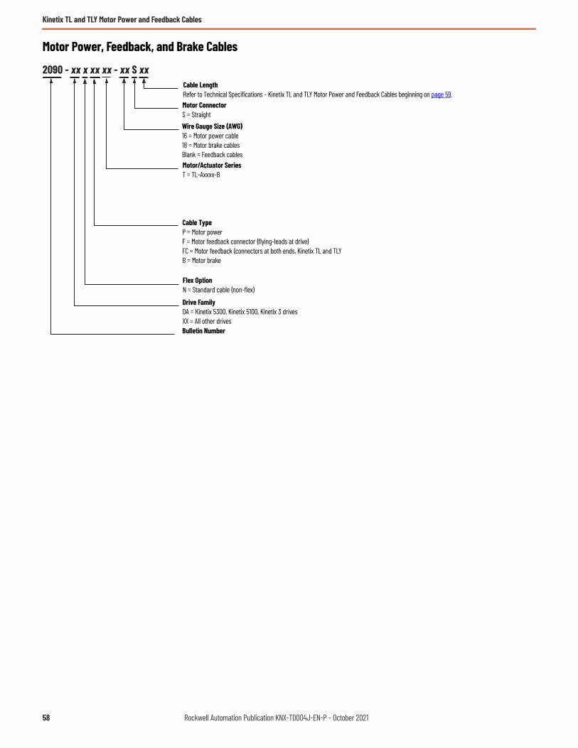
Kinetix TL and TLY Motor Power and Feedback Cables
Motor Power, Feedback, and Brake Cables
2090 - xx x xx xx - xx S xxCable LengthRefer to Technical Specifications - Kinetix TL and TLY Motor Power and Feedback Cables beginning on page 59.Motor ConnectorS = StraightWire Gauge Size (AWG) 16 = Motor power cable18 = Motor brake cablesBlank = Feedback cablesMotor/Actuator SeriesT = TL-Axxxx-B
Cable TypeP = Motor powerF = Motor feedback connector (flying-leads at drive)FC = Motor feedback (connectors at both ends, Kinetix TL and TLYB = Motor brake
Flex OptionN = Standard cable (non-flex)
Drive FamilyDA = Kinetix 5300, Kinetix 5100, Kinetix 3 drivesXX = All other drivesBulletin Number
58 Rockwell Automation Publication KNX-TD004J-EN-P - October 2021

Kinetix TL and TLY Motor Power and Feedback Cables
Kinetix TL and TLY Power and Feedback Cables OverviewFeedback Cable Descriptions (standard, non-flex)
Power/Brake Cable Descriptions (standard, non-flex)
Technical Specifications - Kinetix TL and TLY Motor Power and Feedback Cables
Power Cable Specifications
Brake Cable Specifications
Standard Cable Cat. No. Description
Cable ConfigurationConnector Type
Motor End Drive End
2090-CFBM6DF-CBAAxx• Drive-end flying-leads (DF)• High-resolution, battery backup or
Incremental applications (CB) Circular Plastic(M6)
2090-CFBM6DD-CCAAxx • Drive-end 15-pin connector (DD)• Incremental applications only (CC)
2090-DANFCT-Sxx • Drive-end 20-pin connector• High-resolution applications Rectangular Plastic
Standard Cable Cat. No. Description
Cable ConfigurationConnector Type
Motor End Drive End
2090-CPBM6DF-16AAxx • Drive-end flying-leads (DF)• Power/brake wires (PB) Circular Plastic
(M6)
2090-CPWM6DF-16AAxx • Drive-end flying-leads (DF)• Power wires only (PW)
2090-DANPT-16Sxx • Drive-end flying-leads• Power wires only Rectangular Plastic
2090-DANBT-18Sxx Drive-end flying-lead brake wires
IMPORTANT Maximum motor cable length depends on the feedback type and overall system design. The drive-system power supply, AC input-power type, and AC input voltage are among the configuration variables. For more information on maximum cable lengths see your servo drive user manual or the Kinetix 5700, 5500, 5300, 5100 Servo Drives Specifications Technical Data, publicationKNX-TD003.
Power Cables Cat. No.
Cable Type/Jacket Color Description Wire Size
AWGWeight, approxkg/m (lb/ft)
Standard Cable Lengthsm (ft)
2090-CPWM6DF-16AAxxStandard (non-flex) cable, Industrial TPE,Black
Four conductor, 600V, shielded cable for three-phase power.
160.138 (0.093) 01 (3.2)
02 (6.5)03 (9.8)04 (13.1)
05 (16.4)07 (22.9)09 (29.5)12 (39.4)
15 (49.2)20 (65.6)25 (82.0)30 (98.4)
2090-DANPT-16Sxx 16
2090-CPBM6DF-16AAxxFour conductor, 600V, shielded cable for three-phase power with additional two conductors 18 AWG for motor brake.
16 0.180 (0.121)
Brake CablesCat. No.
Cable Type/Jacket Color Description Wire Size
AWGWeight, approxkg/m (lb/ft)
Standard Cable Lengthsm (ft)
2090-DANBT-18SxxStandard (non-flex) cable, Industrial TPE,Black
Two conductor, 600V, 18 AWG, shielded cable for motor brake. 18 0.070 (0.047)
01 (3.2)02 (6.5)03 (9.8)04 (13.1)
05 (16.4)07 (22.9)09 (29.5)12 (39.4)
15 (49.2)20 (65.6)25 (82.0)30 (98.4)
MBRK+
MBRK-
Rockwell Automation Publication KNX-TD004J-EN-P - October 2021 59

Kinetix TL and TLY Motor Power and Feedback Cables
Feedback Cable Specifications
Dimensions - Kinetix TL and TLY Motor Power and Feedback Cables
When installing cable runs between the motor and drive, be careful not to stress the cable by making bends too sharp. Refer to the table below for bend radius definitions, and the dimension diagrams that follow, when routing cables during system installation.
Motor Power and Feedback Cable Bend Radius Definitions
Power Cable Dimensions (catalog number 2090-CPxM6DF-16AAxx)
Feedback CablesCat. No.
Cable Type/Jacket Color Description Wire Size
AWGWeight, approxkg/m (lb/ft)
Standard Cable Lengthsm (ft)
2090-CFBM6DF-CBAAxx
Standard (non-flex) cable, Industrial TPE,Black
Circular plastic connector (motor end) to flying leads (drive end), 300V.
28 Feedback16 Power, 5V22 BAT+ 0.120 (1.35) 01 (3.2)
02 (6.5)03 (9.8)04 (13.1)
05 (16.4)07 (22.9)09 (29.5)12 (39.4)
15 (49.2)20 (65.6)25 (82.0)30 (98.4)
2090-CFBM6DD-CCAAxx Circular plastic connector (motor end) to premolded connector (drive end), 300V.
28 Feedback16 Power, 5V
2090-DANFCT-Sxx Rectangular plastic connector (motor end) to premolded connector (drive end), 30V.
28 Feedback16 Power, 5V22 BAT+
0.130 (0.088)
Type of Bend Radius Type of Cable Description
Static bend radius Standard (non-flex)
The static (installation) bend radius and dimension B are 7 times the cable diameter:• Do not begin a static bend inside dimension B.• Use this measurement when routing the cable in a non-flex application between motor and drive (the bend area).
– The bend area is where standard (non-flex) or continuous-flex cables can be bent to their specified bend radius.
MBRK+
MBRK-
9.2(0.36)
28.0(1.10) 2090-CPWM6DF-16AAxx
2090-CPBM6DF-16AAxx
12.2(0.48)
50.8(2.0)
BrownBlackBlueGreen/Yellow
Cable Shield(for brake wires)
Cable Shield (overall)
BrownBlackBlueGreen/Yellow
Cable Shield (overall)
CableDiameter
CableDiameter
ConnectorDiameter
Dimensions are in mm (in.)(reference only)
60 Rockwell Automation Publication KNX-TD004J-EN-P - October 2021
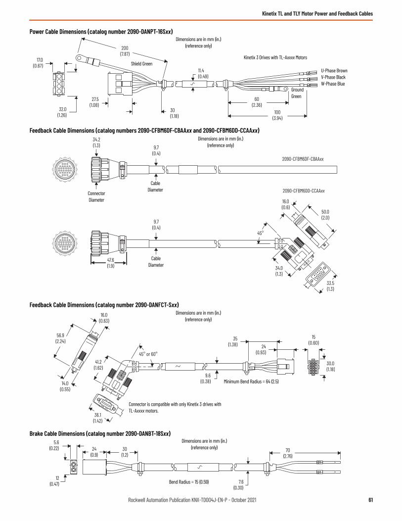
Kinetix TL and TLY Motor Power and Feedback Cables
Power Cable Dimensions (catalog number 2090-DANPT-16Sxx)
Feedback Cable Dimensions (catalog numbers 2090-CFBM6DF-CBAAxx and 2090-CFBM6DD-CCAAxx)
Feedback Cable Dimensions (catalog number 2090-DANFCT-Sxx)
Brake Cable Dimensions (catalog number 2090-DANBT-18Sxx)
60(2.36)
100(3.94)
11.4(0.49)
200(7.87)
30(1.18)
17.0(0.67)
27.5(1.08)
32.0(1.26)
U-Phase BrownV-Phase BlackW-Phase Blue
Shield Green
GroundGreen
Kinetix 3 Drives with TL-Axxxx Motors
Dimensions are in mm (in.)(reference only)
16.0(0.6)
50.0(2.0)
33.5(1.3)
34.0(1.3)
45°
47.6(1.9)
9.7(0.4)
2090-CFBM6DF-CBAAxx
2090-CFBM6DD-CCAAxx
34.2(1.3)
9.7(0.4)
ConnectorDiameter
CableDiameter
CableDiameter
Dimensions are in mm (in.)(reference only)
45° or 60°
35(1.38) 24
(0.93)
30.0(1.18)
15(0.60)
9.6(0.38)
16.0(0.63)
56.9(2.24)
14.0(0.55)
41.2(1.62)
36.1(1.42)
Minimum Bend Radius = 64 (2.5)
Connector is compatible with only Kinetix 3 drives with TL-Axxxx motors.
Dimensions are in mm (in.)(reference only)
12(0.47)
24(0.9)
5.6(0.22)
7.6(0.30)
70(2.76)
30(1.2)
Bend Radius = 15 (0.59)
Dimensions are in mm (in.)(reference only)
Rockwell Automation Publication KNX-TD004J-EN-P - October 2021 61

Kinetix TLP Motor Power and Feedback Cables
Kinetix TLP Motor Power and Feedback CablesKinetix TLP power and feedback cables are designed specifically for applications with Kinetix TLP servo motors and Kinetix 5100 or Kinetix 5300 drives. Cables equipped with rectangular connectors mate with the on-motor cables that are included with TLP-A046, TLP-A/B070, TLP-A/B090, and TLP-A100 motors. Cables equipped with military style connectors mate with all other (larger) Kinetix TLP servo motors. Standard (non-flex) motor power and feedback cables are available, as are continuous-flex rated cables that are intended for moving applications. Continuous-flex extension cables are also available for your applications that require them.
The Kinetix TLP power and feedback cables are designed to match with Kinetix TLP servo motors and Kinetix 5100 or Kinetix 5300 drives for optimal system performance. Kinetix TLP cables offer up to 50 m (164 ft) in length and a variety of options for your application needs.
Kinetix TLP Motor Cable Features• UL Recognized: 18, 16, 12, 8, 6, and 4 AWG power cable
- UL AWM, 600V, 105 °C construction- cUR AWM I/II A, 600V, 105 °C construction
• UL Recognized: Feedback cable- UL AWM, 300V, 80 °C construction for up to 20 m (65.6 ft) cable length- UL AWM, 30V, 80 °C construction for 30 m (98.4 ft) and 50 m (164 ft) cable length
• UL Recognized: Brake cable- UL AWM, 300V, 105 °C construction
• Molded connectors for 16 and 18 AWG, military style connectors for 16…4 AWG• PVC cable jacket• Tested for EMC/EMI system performance
IMPORTANT Feedback cables include a drive-end connector, but 2198-K5xCK-D15M feedback connector kits are available and provide drive-end terminations when building your own cables. Refer to Kinetix TLP Motor-end Cable Connector Kits beginning on page 75 for power and feedback cable connector kit catalog numbers and descriptions. Refer to the Kinetix 5700, 5500, 5300, 5100 Servo Drives Specifications Technical Data, publication KNX-TD003, for more information on the 2198-K5xCK-D15M connector kit that is used with Kinetix 5100 and Kinetix 5300 servo drives.
IMPORTANT Standard (non-flex) cables have a regular maintenance and installation bend radius of 7 times the cable diameter. For flexing applications, continuous-flex cables have an operational bend radius of 12 times the cable diameter.
62 Rockwell Automation Publication KNX-TD004J-EN-P - October 2021

Kinetix TLP Motor Power and Feedback Cables
Catalog Numbers - Kinetix TLP Power and Feedback Cables
Catalog numbers consist of various characters, each of which identifies a specific option for that component. Use the catalog numbering charts below to understand the configuration of your component. For questions regarding product availability, contact your Allen-Bradley distributor.
2090 - C T xx - xx xx - xx x xxCable LengthRefer to Technical Specifications - Kinetix TLP Power and Feedback Cables beginning on page 68.
Wire Gauge Size (PB, PW, and BK cable types)20, 18, 16, 14, 12,10, 08, 06, and 04 AWG
Cable TypePB = Motor power with brake wiresPW = Motor power onlyFB = Motor feedbackBK = Motor brake
Cable TypeA = Standard, non-flexF = Continuous-flex
Accessory ComponentC = CableBulletin Number
Drive-end Connector TypeDF = Flying-lead power and brake cableDD = Premolded connector on feedback cableET = Extension receptacle on power, feedback, and brake cables
Motor-end Connector Type (PB and PW cable type)MA = Rectangular, applies to TLP-A046, TLP-A/B070, TLP-A/B090, and TLP-A100 motorsMC = Military style, applies to TLP-A/B115-xxx and TLP-A/B145-xxx motorsMD = Military style, applies to TLP-A/B200-200, TLP-A/B200-300, TLP-A/B200-350, and TLP-A/B200-450 motorsME = Military style, applies to TLP-A/B200-550, and TLP-A/B200-750 and TLP-A/B235-xxx motors
Matching Motor FamilyT = Compatible with Kinetix TLP servo motors
Motor-end Connector Type (FB cable type)MA = Rectangular, applies to TLP-A046, TLP-A/B070, TLP-A/B090, and TLP-A100 motorsMF = Military style, applies to TLP-A/B115, TLP-A/B145, TLP-A/B200, and TLP-A/B235 motors
Motor-end Connector Type (BK cable type)MB = Military style, applies to TLP-A/B200-550, and TLP-A/B200-750 and TLP-A/B235-xxx motors
Encoder Type (FB cable types)CF = Serial absolute, battery backup
Rockwell Automation Publication KNX-TD004J-EN-P - October 2021 63

Kinetix TLP Motor Power and Feedback Cables
Kinetix TLP Motor Cables Overview
2090-CTPx-MADF cables attach to on-motor cable connectors. 2090-CTPx-MC/D/E cables attach to military-style connectors. 2090-CTPx-MxET extension cables provide continuous-flex cable technology between your standard (non-flex) cable and the continuous-flex application.
Power/Brake Cable Descriptions (standard, non-flex)
Power/Brake Cable Descriptions (continuous-flex)
Standard Cable Cat. No. Description
Cable ConfigurationMotor Connector
Motor End Drive End
2090-CTPB-MADF-xxAxx
• Applies to TLP-A046, TLP-A/B070, TLP-A/B090, and TLP-A100 motors (MA)
• Drive-end flying-leads (DF)• Power/brake wires (PB)
Rectangular
2090-CTPW-MADF-xxAxx
• Applies to TLP-A046, TLP-A/B070, TLP-A/B090, and TLP-A100 motors (MA)
• Drive-end flying-leads (DF)• Power wires only (PW)
2090-CTPB-MCDF-xxAxx2090-CTPB-MDDF-xxAxx
• Applies to TLP-A/B115…TLP-A/B145 motors (MC)• Applies to TLP-A/B200 (MD)• Drive-end flying-leads (DF)• Power/brake wires (PB)
Military style2090-CTPW-MCDF-xxAxx2090-CTPW-MDDF-xxAxx2090-CTPW-MEDF-xxAxx
• Applies to TLP-A/B115…TLP-A/B145 motors (MC)• Applies to TLP-A/B200 motors (MD)• Applies to TLP-A/B200…TLP-A/B235 motors (ME)• Drive-end flying-leads (DF)• Power wires only (PW)
Continuous-flex Cable Cat. No. Description
Cable ConfigurationMotor Connector
Motor End Drive End
2090-CTPB-MADF-xxFxx
• Applies to TLP-A046, TLP-A/B070, TLP-A/B090, and TLP-A100 motors (MA)
• Drive-end flying-leads (DF)• Power/brake wires (PB)
Rectangular2090-CTPW-MADF-xxFxx
• Applies to TLP-A046, TLP-A/B070, TLP-A/B090, and TLP-A100 motors (MA)
• Drive-end flying-leads (DF)• Power wires only (PW)
2090-CTPB-MAET-xxFxx2090-CTPW-MAET-xxFxx
• Applies to TLP-A046, TLP-A/B070, TLP-A/B090, and TLP-A100 motors (MA)
• Drive-end (male) connector, extension (ET)• Power/brake wires (PB)• Power wires only (PW)
2090-CTPB-MCDF-xxFxx2090-CTPB-MDDF-xxFxx
• Applies to TLP-A/B115…TLP-A/B145 motors (MC)• Applies to TLP-A/B200 motors (MD)• Drive-end flying-leads (DF)• Power/brake wires (PB)
Military style2090-CTPW-MCDF-xxFxx2090-CTPW-MDDF-xxFxx2090-CTPW-MEDF-xxFxx
• Applies to TLP-A/B115…TLP-A/B145 motors (MC)• Applies to TLP-A/B200 motors (MD)• Applies to TLP-A/B200 motors (ME)• Drive-end flying-leads (DF)• Power wires only (PW)
2090-CTPB-MCET-xxFxx2090-CTPB-MDET-xxFxx
• Applies to TLP-A/B115…TLP-A/B145 motors (MC)• Applies to TLP-A/B200 (MD)• Drive-end (male) connector, extension (ET)• Power/brake wires (PB)
Military style2090-CTPW-MCET-xxFxx2090-CTPW-MDET-xxFxx2090-CTPW-MEET-xxFxx
• Applies to TLP-A/B115…TLP-A/B145 motors (MC)• Applies to TLP-A/B200 motors (MD)• Applies to TLP-A/B200…TLP-A/B235 motors (ME)• Drive-end (male) connector, extension (ET)• Power wires only (PW)
64 Rockwell Automation Publication KNX-TD004J-EN-P - October 2021

Kinetix TLP Motor Power and Feedback Cables
Brake wires for TLP-A/B200-550, TLP-A/B200-750, and TLP-A/B235-xxx servo motors are in a separate cable. 2090-CTBK-MBET extension cables provide continuous-flex cable technology between your standard (non-flex) cable and the continuous-flex application.
Brake Cable Descriptions (standard, non-flex)
Brake Cable Descriptions (continuous-flex)
2090-CTFB-MADD cables attach to the on-motor cable. 2090-CTFB-MFDD cables attach to the motor feedback connector. Drive-end connectors attach to Kinetix 5100 and Kinetix 5300 feedback connectors.
2090-CTFB-MxET extension cables provide continuous-flex cable technology between your standard (non-flex) cable and the continuous-flex application.
Feedback Cable Descriptions (standard, non-flex)
Feedback Cable Descriptions (continuous-flex)
Standard Cable Cat. No. Description
Cable ConfigurationMotor Connector
Motor End Drive End
2090-CTBK-MBDF-20Axx
• Applies to TLP-A/B200-550, TLP-A/B200-750, and TLP-A/B235-xxx motors (MB)
• Drive-end flying-leads (DF)• Brake wires (BK)
Military style
Continuous-flex Cable Cat. No. Description
Cable ConfigurationMotor Connector
Motor End Drive End
2090-CTBK-MBDF-20Fxx
• Applies to TLP-A/B200-550, TLP-A/B200-750, and TLP-A/B235-xxx motors (MB)
• Drive-end flying-leads (DF)• Brake wires (BK)
Military style
2090-CTBK-MBET-20Fxx
• Applies to TLP-A/B200-550, TLP-A/B200-750, and TLP-A/B235-xxx motors (MB)
• Drive-end (male) connector, extension (ET)• Brake wires (BK)
Standard Cable Cat. No. Description
Cable ConfigurationMotor Connector
Motor End Drive End
2090-CTFB-MADD-CFAxx
• Applies to TLP-A046, TLP-A/B070, TLP-A/B090, and TLP-A100 motors (MA)
• Battery box for Kinetix TLP and TL/TLY encoders• Feedback connector (FB)
Rectangular
2090-CTFB-MFDD-CFAxx• Applies to TLP-A/B115…TLP-A/B235 motors (MF)• Battery box for Kinetix TLP and TL/TLY encoders• Feedback connector (FB)
Military style
Standard Cable Cat. No. Description
Cable ConfigurationMotor Connector
Motor End Drive End
2090-CTFB-MADD-CFFxx
• Applies to TLP-A046, TLP-A/B070, TLP-A/B090, and TLP-A100 motors (MA)
• Battery box for Kinetix TLP and TL/TLY encoders• Feedback connector (FB)
Rectangular
2090-CTFB-MFDD-CFFxx• Applies to TLP-A/B115…TLP-A/B235 motors (MF)• Battery box for Kinetix TLP and TL/TLY encoders• Feedback connector (FB)
Military style
2090-CTFB-MAET-CFFxx
• Applies to TLP-A046, TLP-A/B070, TLP-A/B090, and TLP-A100 motors (MA)
• Drive-end (male) connector, extension (ET)• Feedback connector (FB)
Rectangular
2090-CTFB-MEET-CFFxx• Applies to TLP-A/B115…TLP-A/B235 motors (MF)• Drive-end (male) connector, extension (ET)• Feedback connector (FB)
Military style
Battery Box
Battery Box
Battery Box
Battery Box
Rockwell Automation Publication KNX-TD004J-EN-P - October 2021 65

Kinetix TLP Motor Power and Feedback Cables
Motor Connector/Cable Compatibility
TLP-A046, TLP-A/B070, TLP-A/B090, and TLP-A100 servo motors are equipped with rectangular connectors.
TLP-A/B115, TLP-A/B145, TLP-A/B200, TLP-A/B235 servo motors are equipped with military style connectors.
12
6 5 4
3
12
65
4
3 98
7
• Applies to TLP-A046, TLP-A/B070, TLP-A/B090, and TLP-A100 motors• Receives rectangular cable plugs
• 2090-CTFB-MADD-CFAxx (standard, non-flex) drive-end connector feedback cables• 2090-CTFB-MADD-CFFxx (continuous-flex) drive-end connector feedback cables
• 2090-CTPB-MADF-xxAxx (standard, non-flex) power/brake cables• 2090-CTPB-MADF-xxFxx (continuous-flex) power/brake cables• 2090-CTPW-MADF-xxAxx (standard, non-flex) power-only cables• 2090-CTPW-MADF-xxFxx (continuous-flex) power-only cables
• TLP-A/B115…TLP-A/B145 motors• Receives military style cable plugs
• 2090-CTFB-MFDD-CFAxx (standard, non-flex) drive-end connector feedback cables• 2090-CTFB-MFDD-CFFxx (continuous-flex) drive-end connector feedback cables
• 2090-CTPB-MCDF-xxAxx (standard, non-flex) power/brake cables• 2090-CTPB-MCDF-xxFxx (continuous-flex) power/brake cables• 2090-CTPW-MCDF-xxAxx (standard, non-flex) power-only cables• 2090-CTPW-MCDF-xxFxx (continuous-flex) power-only cables
• 2090-CTBK-MBDF-xxAxx (standard, non-flex) flying-lead brake cables• 2090-CTFB-MBDF-xxFxx (continuous-flex) flying-lead brake cables
• TLP-A/B200-550, TLP-A/B200-750 and TLP-A/B235 motors with holding brake option
• Receives military style cable plugs
• 2090-CTPW-MEDF-xxAxx (standard, non-flex) power-only cables• 2090-CTPW-MEDF-xxFxx (continuous-flex) power-only cables
• 2090-CTPB-MDDF-xxAxx (standard, non-flex) power/brake cables• 2090-CTPB-MDDF-xxFxx (continuous-flex) power/brake cables• 2090-CTPW-MDDF-xxAxx (standard, non-flex) power-only cables• 2090-CTPW-MDDF-xxFxx (continuous-flex) power-only cables• TLP-A/B115…TLP-A/B235 motors
• Receives military style cable plugs
• TLP-A/B200-200, TLP-A/B200-300, TLP-A/B200-350, and TLP-A/B200-450 motors
• Receives military style cable plugs
66 Rockwell Automation Publication KNX-TD004J-EN-P - October 2021

Kinetix TLP Motor Power and Feedback Cables
Kinetix TLP Motor Cable Selection
This table provides motor cable catalog numbers for use with Kinetix TLP servo motors. Motor power, feedback, and motor brakes (if applicable) cables are specified. The IP rating is dependent on the use of Kinetix 2090 cables as listed in the table.
Kinetix TLP Motor and Cable Combinations
IMPORTANT Maximum motor cable length depends on the feedback type. For more information on maximum cable lengths, see your servo drive user manual or the Kinetix 5700, 5500, 5300, 5100 Servo Drives Specifications Technical Data, publication KNX-TD003.
Rotary Motor (200V-class)
Cat. No. (1)
(1) The TLP-A046…TLP-A100 frame on-motor cables include 18 AWG conductors that are compatible with 2090-CTPx-MADF-18xxx cable conductors.
Motor Power/Brake Cable Feedback Cable Cat. No. Brake Cat. No.TLP-A046-xxx, TLP-A070-xxx, TLP-A090-xxx, (2)
TLP-A100-xxx
(2) For TLP-A090-xxx motors, use 2090-CTPx-MADF-16xxx motor power/brake cable to comply with NFPA 79 requirements.
2090-CTPx-MADF-18Axx (standard) or2090-CTPx-MADF-18Fxx (continuous-flex)
2090-CTFB-MADD-CFAxx (standard) or2090-CTFB-MADD-CFFxx (continuous-flex)
Not applicable. Brake conductors are included in the power cable.
TLP-A115-100, (3)
TLP-A145-050, TLP-A145-100
(3) For TLP-A115-100 motors, use 2090-CTPx-MCDF-12xxx motor power/brake cable to comply with NFPA 79 requirements.
2090-CTPx-MCDF-16Axx (standard) or2090-CTPx-MCDF-16Fxx (continuous-flex)
2090-CTFB-MFDD-CFAxx (standard) or2090-CTFB-MFDD-CFFxx (continuous-flex)
TLP-A115-200, TLP-A145-090, TLP-A145-150, TLP-A145-250
2090-CTPx-MCDF-12Axx (standard) or2090-CTPx-MCDF-12Fxx (continuous-flex)
TLP-A200-200, TLP-A200-300, TLP-A200-350 (4)
(4) For TLP-A200-350 motors, use 2090-CTPx-MDDF-08xxx motor power/brake cable to comply with NFPA 79 requirements.
2090-CTPx-MDDF-12Axx (standard) or2090-CTPx-MDDF-12Fxx (continuous-flex)
TLP-A200-450 2090-CTPx-MDDF-08Axx (standard) or2090-CTPx-MDDF-08Fxx (continuous-flex)
TLP-A200-550, TLP-A200-750, TLP-A235-11K (5) (6)
(5) For TLP-A235-11K motors, use 2090-CTPx-MEDF-04xxx motor power cable to comply with NFPA 79 requirements.(6) Only these motors have separate brake connectors and brake cables. All other motors have brake wires included with the motor power/brake connector.
2090-CTPW-MEDF-06Axx (standard) or2090-CTPW-MEDF-06Fxx (continuous-flex)
2090-CTBK-MBDF-20Axx (standard) or2090-CTBK-MBDF-20Fxx (continuous-flex)TLP-A235-15K (7) (6)
(7) For TLP-A235-15K motors, you must build your own motor power cable to comply with NFPA 79 requirements.
2090-CTPW-MEDF-04Axx (standard) or2090-CTPW-MEDF-04Fxx (continuous-flex)
Rotary Motor (400V-class)
Cat. No. (1)
(1) The TLP-B070-040 and TLP-B090-075 frame on-motor cables include 18 AWG conductors that are compatible with 2090-CTPx-MADF-18xxx cable conductors.
Motor Power/Brake Cable Feedback Cable Cat. No. Brake Cat. No.
TLP-B070-040TLP-B090-075
2090-CTPx-MADF-18Axx (standard) or2090-CTPx-MADF-18Fxx (continuous-flex)
2090-CTFB-MADD-CFAxx (standard) or2090-CTFB-MADD-CFFxx (continuous-flex)
Not applicable. Brake conductors are included in the power cable.
TLP-B115-100, TLP-B115-200 (2)
TLP-B145-050, TLP-B145-100TLP-B145-150, TLP-B145-200
(2) For TLP-B115-200 motors, use 2090-CTPx-MCDF-12xxx motor power/brake cable to comply with NFPA 79 requirements.
2090-CTPx-MCDF-16Axx (standard) or2090-CTPx-MCDF-16Fxx (continuous-flex)
2090-CTFB-MFDD-CFAxx (standard) or2090-CTFB-MFDD-CFFxx (continuous-flex)
TLP-B145-250 2090-CTPx-MCDF-12Axx (standard) or2090-CTPx-MCDF-12Fxx (continuous-flex)
TLP-B200-300, TLP-B200-450 2090-CTPx-MDDF-12Axx (standard) or2090-CTPx-MDDF-12Fxx (continuous-flex)
TLP-B200-550, TLP-B200-750 2090-CTPx-MDDF-08Axx (standard) or2090-CTPx-MDDF-08Fxx (continuous-flex)
TLP-B235-11K, TLP-B235-14K (3)
(3) Only these motors have separate brake connectors and brake cables. All other motors have brake wires included with the motor power/brake connector.
2090-CTPW-MEDF-06Axx (standard) or2090-CTPW-MEDF-06Fxx (continuous-flex)
2090-CTBK-MBDF-20Axx (standard) or2090-CTBK-MBDF-20Fxx (continuous-flex)
Rockwell Automation Publication KNX-TD004J-EN-P - October 2021 67
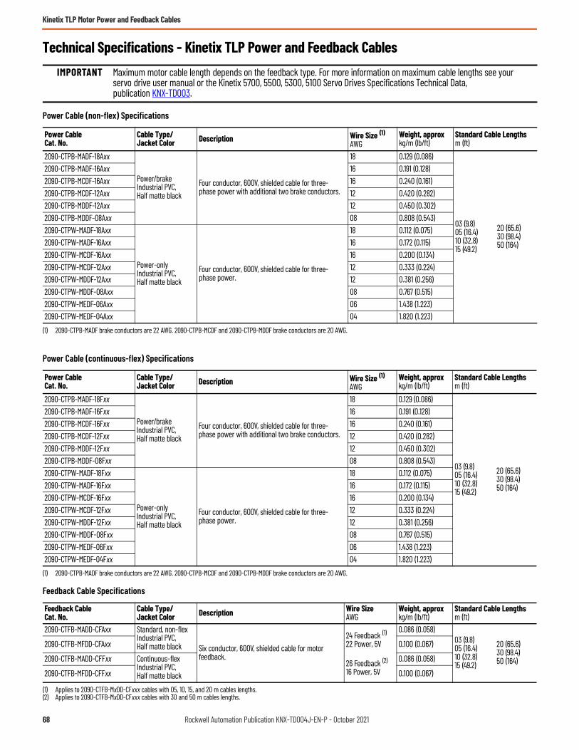
Kinetix TLP Motor Power and Feedback Cables
Technical Specifications - Kinetix TLP Power and Feedback Cables
Power Cable (non-flex) Specifications
Power Cable (continuous-flex) Specifications
Feedback Cable Specifications
IMPORTANT Maximum motor cable length depends on the feedback type. For more information on maximum cable lengths see your servo drive user manual or the Kinetix 5700, 5500, 5300, 5100 Servo Drives Specifications Technical Data, publication KNX-TD003.
Power Cable Cat. No.
Cable Type/Jacket Color Description Wire Size (1)
AWG
(1) 2090-CTPB-MADF brake conductors are 22 AWG. 2090-CTPB-MCDF and 2090-CTPB-MDDF brake conductors are 20 AWG.
Weight, approxkg/m (lb/ft)
Standard Cable Lengthsm (ft)
2090-CTPB-MADF-18Axx
Power/brakeIndustrial PVC, Half matte black
Four conductor, 600V, shielded cable for three-phase power with additional two brake conductors.
18 0.129 (0.086)
03 (9.8)05 (16.4)10 (32.8)15 (49.2)
20 (65.6)30 (98.4)50 (164)
2090-CTPB-MADF-16Axx 16 0.191 (0.128)2090-CTPB-MCDF-16Axx 16 0.240 (0.161)2090-CTPB-MCDF-12Axx 12 0.420 (0.282)2090-CTPB-MDDF-12Axx 12 0.450 (0.302)2090-CTPB-MDDF-08Axx 08 0.808 (0.543)2090-CTPW-MADF-18Axx
Power-onlyIndustrial PVC, Half matte black
Four conductor, 600V, shielded cable for three-phase power.
18 0.112 (0.075)2090-CTPW-MADF-16Axx 16 0.172 (0.115)2090-CTPW-MCDF-16Axx 16 0.200 (0.134)2090-CTPW-MCDF-12Axx 12 0.333 (0.224)2090-CTPW-MDDF-12Axx 12 0.381 (0.256)2090-CTPW-MDDF-08Axx 08 0.767 (0.515)2090-CTPW-MEDF-06Axx 06 1.438 (1.223)2090-CTPW-MEDF-04Axx 04 1.820 (1.223)
Power Cable Cat. No.
Cable Type/Jacket Color Description Wire Size (1)
AWG
(1) 2090-CTPB-MADF brake conductors are 22 AWG. 2090-CTPB-MCDF and 2090-CTPB-MDDF brake conductors are 20 AWG.
Weight, approxkg/m (lb/ft)
Standard Cable Lengthsm (ft)
2090-CTPB-MADF-18Fxx
Power/brakeIndustrial PVC, Half matte black
Four conductor, 600V, shielded cable for three-phase power with additional two brake conductors.
18 0.129 (0.086)
03 (9.8)05 (16.4)10 (32.8)15 (49.2)
20 (65.6)30 (98.4)50 (164)
2090-CTPB-MADF-16Fxx 16 0.191 (0.128)2090-CTPB-MCDF-16Fxx 16 0.240 (0.161)2090-CTPB-MCDF-12Fxx 12 0.420 (0.282)2090-CTPB-MDDF-12Fxx 12 0.450 (0.302)2090-CTPB-MDDF-08Fxx 08 0.808 (0.543)2090-CTPW-MADF-18Fxx
Power-onlyIndustrial PVC, Half matte black
Four conductor, 600V, shielded cable for three-phase power.
18 0.112 (0.075)2090-CTPW-MADF-16Fxx 16 0.172 (0.115)2090-CTPW-MCDF-16Fxx 16 0.200 (0.134)2090-CTPW-MCDF-12Fxx 12 0.333 (0.224)2090-CTPW-MDDF-12Fxx 12 0.381 (0.256)2090-CTPW-MDDF-08Fxx 08 0.767 (0.515)2090-CTPW-MEDF-06Fxx 06 1.438 (1.223)2090-CTPW-MEDF-04Fxx 04 1.820 (1.223)
Feedback Cable Cat. No.
Cable Type/Jacket Color Description Wire Size
AWGWeight, approxkg/m (lb/ft)
Standard Cable Lengthsm (ft)
2090-CTFB-MADD-CFAxx Standard, non-flexIndustrial PVC, Half matte black Six conductor, 600V, shielded cable for motor
feedback.
24 Feedback (1)22 Power, 5V
26 Feedback (2)
16 Power, 5V
(1) Applies to 2090-CTFB-MxDD-CFxxx cables with 05, 10, 15, and 20 m cables lengths.(2) Applies to 2090-CTFB-MxDD-CFxxx cables with 30 and 50 m cables lengths.
0.086 (0.058)03 (9.8)05 (16.4)10 (32.8)15 (49.2)
20 (65.6)30 (98.4)50 (164)
2090-CTFB-MFDD-CFAxx 0.100 (0.067)
2090-CTFB-MADD-CFFxx Continuous-flexIndustrial PVC,Half matte black
0.086 (0.058)
2090-CTFB-MFDD-CFFxx 0.100 (0.067)
68 Rockwell Automation Publication KNX-TD004J-EN-P - October 2021

Kinetix TLP Motor Power and Feedback Cables
Brake Cable Specifications
Continuous-flex Extension Cable Specifications
Brake Cable Cat. No.
Cable Type/Jacket Color Description Wire Size
AWGWeight, approxkg/m (lb/ft)
Standard Cable Lengthsm (ft)
2090-CTBK-MBDF-20AxxStandard, non-flexIndustrial PVC, Half matte black Two conductor, 600V, shielded cable for motor
brake power.
20
0.045 (0.030)03 (9.8)05 (16.4)10 (32.8)15 (49.2)
20 (65.6)30 (98.4)50 (164)
2090-CTBK-MBDF-20FxxContinuous-flexIndustrial PVC, Half matte black
20
Extension CableCat. No.
Cable Type/Jacket Color Description Weight, approx
kg/m (lb/ft)Standard Cable Lengthsm (ft)
2090-CTPB-MAET-18Fxx
Power/brakeIndustrial PVC,Half matte black
Four conductor, 600V, shielded cable for three-phase power with additional two brake conductors. Connector plug on motor end to receptacle for mating with power/brake cable.
0.135 (0.091)
03 (9.8)05 (16.4)10 (32.8)
2090-CTPB-MAET-16Fxx 0.216 (0.145)2090-CTPB-MCET-16Fxx 0.275 (0.185)2090-CTPB-MCET-12Fxx 0.456 (0.306)2090-CTPB-MDET-12Fxx 0.482 (0.324)2090-CTPB-MDET-08Fxx 0.869 (0.584)2090-CTPW-MAET-18Fxx
Power-onlyIndustrial PVC, Half matte black
Four conductor, 600V, shielded cable for three-phase power. Connector plug on motor end to receptacle for mating with power cable.
0.112 (0.076)2090-CTPW-MAET-16Fxx 0.190 (0.128)2090-CTPW-MCET-16Fxx 0.200 (0.134)2090-CTPW-MCET-12Fxx 0.378 (0.254)2090-CTPW-MDET-12Fxx 0.441 (0.296)2090-CTPW-MDET-08Fxx 0.829 (0.557)2090-CTPW-MEET-06Fxx 1.537 (1.033)2090-CTPW-MEET-04Fxx 1.920 (1.290)2090-CTFB-MAET-CFFxx Feedback
Industrial PVC, Half matte black
Six conductor, 600V, shielded cable for motor feedback. Connector plug on motor end to receptacle for mating with feedback cable.
0.079 (0.053)
2090-CTFB-MEET-CFFxx 0.128 (0.086)
2090-CTBK-MBET-20FxxBrakeIndustrial PVC, Half matte black
Two conductor, 600V, shielded cable for motor brake power. Connector plug on motor end to receptacle for mating with brake cable.
0.058 (0.039)
Rockwell Automation Publication KNX-TD004J-EN-P - October 2021 69
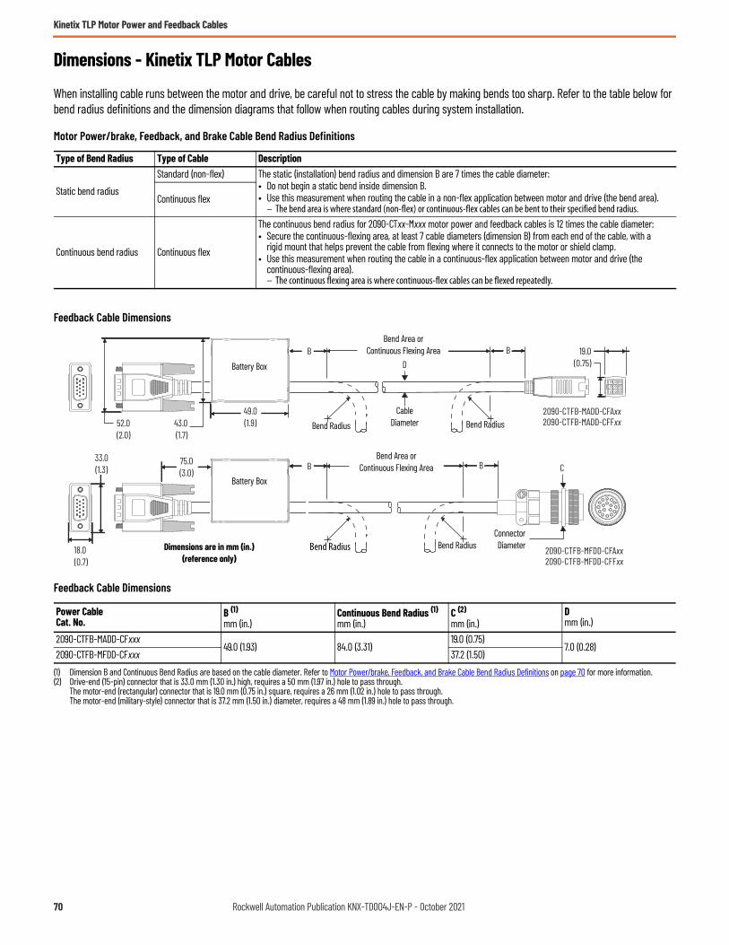
Kinetix TLP Motor Power and Feedback Cables
Dimensions - Kinetix TLP Motor Cables
When installing cable runs between the motor and drive, be careful not to stress the cable by making bends too sharp. Refer to the table below for bend radius definitions and the dimension diagrams that follow when routing cables during system installation.
Motor Power/brake, Feedback, and Brake Cable Bend Radius Definitions
Feedback Cable Dimensions
Feedback Cable Dimensions
Type of Bend Radius Type of Cable Description
Static bend radius
Standard (non-flex) The static (installation) bend radius and dimension B are 7 times the cable diameter:• Do not begin a static bend inside dimension B.• Use this measurement when routing the cable in a non-flex application between motor and drive (the bend area).
– The bend area is where standard (non-flex) or continuous-flex cables can be bent to their specified bend radius.Continuous flex
Continuous bend radius Continuous flex
The continuous bend radius for 2090-CTxx-Mxxx motor power and feedback cables is 12 times the cable diameter:• Secure the continuous-flexing area, at least 7 cable diameters (dimension B) from each end of the cable, with a
rigid mount that helps prevent the cable from flexing where it connects to the motor or shield clamp.• Use this measurement when routing the cable in a continuous-flex application between motor and drive (the
continuous-flexing area).– The continuous flexing area is where continuous-flex cables can be flexed repeatedly.
Power CableCat. No.
B (1)mm (in.)
(1) Dimension B and Continuous Bend Radius are based on the cable diameter. Refer to Motor Power/brake, Feedback, and Brake Cable Bend Radius Definitions on page 70 for more information.
Continuous Bend Radius (1)mm (in.)
C (2)
mm (in.)
(2) Drive-end (15-pin) connector that is 33.0 mm (1.30 in.) high, requires a 50 mm (1.97 in.) hole to pass through.The motor-end (rectangular) connector that is 19.0 mm (0.75 in.) square, requires a 26 mm (1.02 in.) hole to pass through.The motor-end (military-style) connector that is 37.2 mm (1.50 in.) diameter, requires a 48 mm (1.89 in.) hole to pass through.
Dmm (in.)
2090-CTFB-MADD-CFxxx49.0 (1.93) 84.0 (3.31)
19.0 (0.75)7.0 (0.28)
2090-CTFB-MFDD-CFxxx 37.2 (1.50)
2090-CTFB-MADD-CFAxx2090-CTFB-MADD-CFFxx
C
B
B B
2090-CTFB-MFDD-CFAxx2090-CTFB-MFDD-CFFxx
33.0(1.3)
18.0 (0.7)
75.0(3.0)
52.0(2.0)
B
49.0(1.9)43.0
(1.7)
19.0(0.75)D
Bend RadiusDimensions are in mm (in.)(reference only)
CableDiameter
ConnectorDiameter
Bend Area orContinuous Flexing Area
Bend RadiusBend Radius
Bend Area orContinuous Flexing Area
Bend Radius
Battery Box
Battery Box
70 Rockwell Automation Publication KNX-TD004J-EN-P - October 2021

Kinetix TLP Motor Power and Feedback Cables
Power Cable Dimensions (18, 16, 12 AWG cables)
Power CableCat. No.
B (1)mm (in.)
(1) Dimension B and Continuous Bend Radius are based on the cable diameter. Refer to Motor Power/brake, Feedback, and Brake Cable Bend Radius Definitions on page 70 for more information.
Continuous Bend Radius (1)mm (in.)
C (2)
mm (in.)
(2) The motor-end (rectangular) connector that is 19.0 mm (0.75 in.) high, requires a 24 mm (0.94 in.) hole to pass through.The motor-end (military-style) connector that is 37.2 mm (1.50 in.) diameter, requires a 48 mm (1.89 in.) hole to pass through.The motor-end (military-style) connector that is 43.0 (1.69) diameter, requires a 53 mm (2.09 in.) hole to pass through.
Dmm (in.)
2090-CTPB-MADF-18xxx 63.0 (2.48) 108 (4.25)
19.0 (0.75)
9.0 (0.35)2090-CTPB-MADF-16xxx 84.0 (3.31) 144 (5.67) 12.0 (0.47)2090-CTPW-MADF-18xxx 56.7 (2.23) 97.2 (3.83) 8.1 (0.32)2090-CTPW-MADF-16xxx 77.0 (3.03) 132 (5.20) 11.0 (0.43)2090-CTPB-MCDF-16xxx 77.0 (3.03) 132 (5.20)
37.2 (1.46)
11.0 (0.43)2090-CTPB-MCDF-12xxx 101.5 (4.0) 174 (6.85) 14.5 (0.57)2090-CTPW-MCDF-16xxx 77.0 (3.03) 132 (5.20) 11.0 (0.43)2090-CTPW-MCDF-12xxx 101.5 (4.0) 174 (6.85) 14.5 (0.57)2090-CTPB-MDDF-12xxx
101.5 (4.0) 174 (6.85) 43.0 (1.69) 14.5 (0.57)2090-CTPW-MDDF-12xxx
2090-CTPB-MADF-16Axx2090-CTPB-MADF-18Axx2090-CTPB-MADF-16Fxx2090-CTPB-MADF-18Fxx
D
C
B B
B B
2090-CTPW-MADF-16Axx2090-CTPW-MADF-18Axx2090-CTPW-MADF-16Fxx2090-CTPW-MADF-18Fxx
B B
2090-CTPB-MCDF-16Axx2090-CTPB-MCDF-12Axx2090-CTPB-MDDF-12Axx2090-CTPB-MCDF-16Fxx2090-CTPB-MCDF-12Fxx2090-CTPB-MDDF-12Fxx
2090-CTPW-MCDF-16Axx2090-CTPW-MCDF-12Axx2090-CTPW-MDDF-12Axx2090-CTPW-MCDF-16Fxx2090-CTPW-MCDF-12Fxx2090-CTPW-MDDF-12Fxx
B B
16.3 (0.64)
19.0 (0.75)
Bend Radius
Dimensions are in mm (in.)(reference only)
CableDiameter
ConnectorDiameter
Bend Area orContinuous Flexing Area
Bend Radius Bend Radius
Bend Area orContinuous Flexing Area
Bend Radius
Bend Area orContinuous Flexing Area
Bend Radius Bend Radius
Bend Area orContinuous Flexing Area
Bend Radius Bend Radius
Rockwell Automation Publication KNX-TD004J-EN-P - October 2021 71

Kinetix TLP Motor Power and Feedback Cables
Power Cable Dimensions (08, 06, 04 AWG cables)
Brake Cable Dimensions
Brake Cable Dimensions
Power CableCat. No.
B (1)mm (in.)
(1) Dimension B and Continuous Bend Radius are based on the cable diameter. Refer to Motor Power/brake, Feedback, and Brake Cable Bend Radius Definitions on page 70 for more information.
Continuous Bend Radius (1)mm (in.)
C (2)
mm (in.)
(2) The motor-end (military-style) connector that is 43.0 mm (1.69 in.) diameter, requires a 53 mm (2.09 in.) hole to pass through.The motor-end (military-style) connector that is 55.2 mm (2.17 in.) diameter, requires a 65 mm (2.56 in.) hole to pass through.
Dmm (in.)
2090-CTPB-MDDF-08xxx154 (6.06) 264 (10.39) 43.0 (1.69) 22.0 (0.87)
2090-CTPW-MDDF-08xxx2090-CTPW-MEDF-06xxx 196 (7.72) 336 (13.23)
55.2 (2.17)28.0 (1.10)
2090-CTPW-MEDF-04xxx 224 (8.82) 384 (15.12) 32.0 (1.26)
Power CableCat. No.
B (1)mm (in.)
(1) Dimension B and Continuous Bend Radius are based on the cable diameter. Refer to Motor Power/brake, Feedback, and Brake Cable Bend Radius Definitions on page 70 for more information.
Continuous Bend Radius (1)mm (in.)
C (2)
mm (in.)
(2) The motor-end (military-style) connector that is 23.0 mm (0.91 in.) diameter, requires 28.0 mm (1.10 in.) hole to pass through.
Dmm (in.)
2090-CTBK-MBDF-20xxx 38.5 (1.52) 66.0 (2.60) 23.0 (0.91) 5.5 (0.22)
B B
B B
2090-CTPW-MEDF-06Axx2090-CTPW-MEDF-04Axx2090-CTPW-MEDF-06Fxx2090-CTPW-MEDF-04Fxx
2090-CTPB-MDDF-08Axx2090-CTPB-MDDF-08Fxx
2090-CTPW-MDDF-08Axx2090-CTPW-MDDF-08Fxx
C
D
B B
Bend Radius
Dimensions are in mm (in.)(reference only)
ConnectorDiameter
Bend Area orContinuous Flexing Area
Bend Radius Bend Radius
Bend Area orContinuous Flexing Area
Bend Radius
Bend Area orContinuous Flexing Area
Bend Radius Bend Radius
CableDiameter
2090-CTBK-MBDF-20Axx2090-CTBK-MBDF-20Fxx
D
CB B
Dimensions are in mm (in.)(reference only)
CableDiameterConnector
Diameter
Bend Area orContinuous Flexing Area
Bend Radius Bend Radius
72 Rockwell Automation Publication KNX-TD004J-EN-P - October 2021
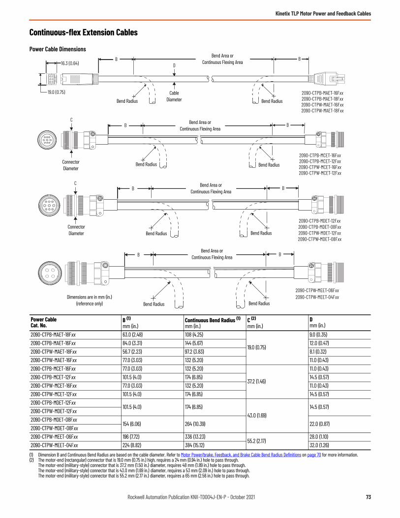
Kinetix TLP Motor Power and Feedback Cables
Continuous-flex Extension Cables
Power Cable Dimensions
Power CableCat. No.
B (1)mm (in.)
(1) Dimension B and Continuous Bend Radius are based on the cable diameter. Refer to Motor Power/brake, Feedback, and Brake Cable Bend Radius Definitions on page 70 for more information.
Continuous Bend Radius (1)mm (in.)
C (2)
mm (in.)
(2) The motor-end (rectangular) connector that is 19.0 mm (0.75 in.) high, requires a 24 mm (0.94 in.) hole to pass through.The motor-end (military-style) connector that is 37.2 mm (1.50 in.) diameter, requires 48 mm (1.89 in.) hole to pass through.The motor-end (military-style) connector that is 43.0 mm (1.69 in.) diameter, requires a 53 mm (2.09 in.) hole to pass through.The motor-end (military-style) connector that is 55.2 mm (2.17 in.) diameter, requires a 65 mm (2.56 in.) hole to pass through.
Dmm (in.)
2090-CTPB-MAET-18Fxx 63.0 (2.48) 108 (4.25)
19.0 (0.75)
9.0 (0.35)2090-CTPB-MAET-16Fxx 84.0 (3.31) 144 (5.67) 12.0 (0.47)2090-CTPW-MAET-18Fxx 56.7 (2.23) 97.2 (3.83) 8.1 (0.32)2090-CTPW-MAET-16Fxx 77.0 (3.03) 132 (5.20) 11.0 (0.43)2090-CTPB-MCET-16Fxx 77.0 (3.03) 132 (5.20)
37.2 (1.46)
11.0 (0.43)2090-CTPB-MCET-12Fxx 101.5 (4.0) 174 (6.85) 14.5 (0.57)2090-CTPW-MCET-16Fxx 77.0 (3.03) 132 (5.20) 11.0 (0.43)2090-CTPW-MCET-12Fxx 101.5 (4.0) 174 (6.85) 14.5 (0.57)2090-CTPB-MDET-12Fxx
101.5 (4.0) 174 (6.85)43.0 (1.69)
14.5 (0.57)2090-CTPW-MDET-12Fxx2090-CTPB-MDET-08Fxx
154 (6.06) 264 (10.39) 22.0 (0.87)2090-CTPW-MDET-08Fxx2090-CTPW-MEET-06Fxx 196 (7.72) 336 (13.23)
55.2 (2.17)28.0 (1.10)
2090-CTPW-MEET-04Fxx 224 (8.82) 384 (15.12) 32.0 (1.26)
2090-CTPB-MAET-16Fxx2090-CTPB-MAET-18Fxx2090-CTPW-MAET-16Fxx2090-CTPW-MAET-18Fxx
2090-CTPB-MCET-16Fxx2090-CTPB-MCET-12Fxx2090-CTPW-MCET-16Fxx2090-CTPW-MCET-12Fxx
2090-CTPB-MDET-12Fxx2090-CTPB-MDET-08Fxx2090-CTPW-MDET-12Fxx2090-CTPW-MDET-08Fxx
D
C
B B
B B
B BC
2090-CTPW-MEET-06Fxx2090-CTPW-MEET-04Fxx
B B
16.3 (0.64)
19.0 (0.75)
Bend Radius
Dimensions are in mm (in.)(reference only)
CableDiameter
ConnectorDiameter
Bend Area orContinuous Flexing Area
Bend RadiusBend Radius
Bend Area orContinuous Flexing Area
Bend Radius
Bend Area orContinuous Flexing Area
Bend RadiusBend Radius
Bend Radius
ConnectorDiameter
Bend Area orContinuous Flexing Area
Bend Radius
Rockwell Automation Publication KNX-TD004J-EN-P - October 2021 73

Kinetix TLP Motor Power and Feedback Cables
Feedback Cable Dimensions
Feedback Cable Dimensions
Brake Cable Dimensions
Brake Cable Dimensions
Power CableCat. No.
B (1)mm (in.)
(1) Dimension B and Continuous Bend Radius are based on the cable diameter. Refer to Motor Power/brake, Feedback, and Brake Cable Bend Radius Definitions on page 70 for more information.
Continuous Bend Radius (1)mm (in.)
C (2)
mm (in.)
(2) The motor-end (rectangular) connector that is 19.0 mm (0.75 in.) square, requires a 26 mm (1.02 in.) hole to pass through.The motor-end (military-style) connector that is 37.2 mm (1.50 in.) diameter, requires a 48 mm (1.89 in.) hole to pass through.
Dmm (in.)
2090-CTFB-MAET-CFFxx49.0 (1.93) 84.0 (3.31)
19.0 (0.75)7.0 (0.28)
2090-CTFB-MEET-CFFxx 37.2 (1.50)
Power CableCat. No.
B (1)mm (in.)
(1) Dimension B and Continuous Bend Radius are based on the cable diameter. Refer to Motor Power/brake, Feedback, and Brake Cable Bend Radius Definitions on page 70 for more information.
Continuous Bend Radius (1)mm (in.)
C (2)
mm (in.)
(2) The motor-end (military-style) connector that is 23.0 mm (0.91 in.) diameter, requires a 28.0 mm (1.10 in.) hole to pass through.
Dmm (in.)
2090-CTBK-MBET-20Fxx 38.5 (1.52) 66.0 (2.60) 23.0 (0.91) 5.5 (0.22)
2090-CTFB-MAET-CFFxx
C
B B
2090-CTFB-MFET-CFFxx
DB B
19.0 (0.75)
19.0 (0.75) Dimensions are in mm (in.)(reference only)
CableDiameterConnector
Diameter
Bend Area orContinuous Flexing Area
Bend RadiusBend Radius
Bend Area orContinuous Flexing Area
Bend Radius Bend Radius
2090-CTBK-MBET-20Fxx
D
CB B
Dimensions are in mm (in.)(reference only)
CableDiameterConnector
Diameter
Bend Area orContinuous Flexing Area
Bend RadiusBend Radius
74 Rockwell Automation Publication KNX-TD004J-EN-P - October 2021

Kinetix TLP Motor Power and Feedback Cables
Kinetix TLP Motor-end Cable Connector Kits
Motor-end connector kits are available for building your own cables. These kits are intended for Kinetix TLP cable connectors.
Kinetix TLP Motor-end Cable Connector Kits
See Build Your Own Kinetix TLP Motor Cables Installation Instructions, publication 2090-IN048, for more information.
Cable Type Motor Cat. No. Connector Kit Cat. No. Description
Rectangular TLP-A046-xxx, TLP-A/B070-xxx, TLP-A/B090-xxx, TLP-A100-xxx
6-pin motor power
2090-KTPC-MA-AA Straight power connector on motor end.2090-KTPC-MA-AE Straight power connector with extension connector.
9-pin motor feedback
2090-KTFB-MA-AA Straight feedback connector.2090-KTFB-MA-AE Straight feedback connector with extension connector.
Military style
TLP-A/B115-xxx, TLP-A/B235-xxx2090-KTFB-MF-AA Straight feedback connector.2090-KTFB-MF-AE Straight feedback connector with extension connector.
TLP-A/B115-xxx, TLP-A/B145-xxx2090-KTPC-MC-AA Straight power connector.2090-KTPC-MC-AE Straight power connector with extension connector.
TLP-A/B200-200, TLP-A/B200-300, TLP-A/B200-350, TLP-A/B200-450
2090-KTPC-MD-AA Straight power connector.2090-KTPC-MD-AE Straight power connector with extension connector.
TLP-A/B200-550, TLP-A/B200-750, TLP-A/B235-xxx
2090-KTPC-ME-AA Straight power connector.2090-KTPC-ME-AE Straight power connector with extension connector.2090-KTBK-MB-AA Straight brake connector.2090-KTBK-MB-AE Straight brake connector with extension connector.
Rockwell Automation Publication KNX-TD004J-EN-P - October 2021 75

Kinetix TLP Motor Power and Feedback Cables
Notes:
76 Rockwell Automation Publication KNX-TD004J-EN-P - October 2021
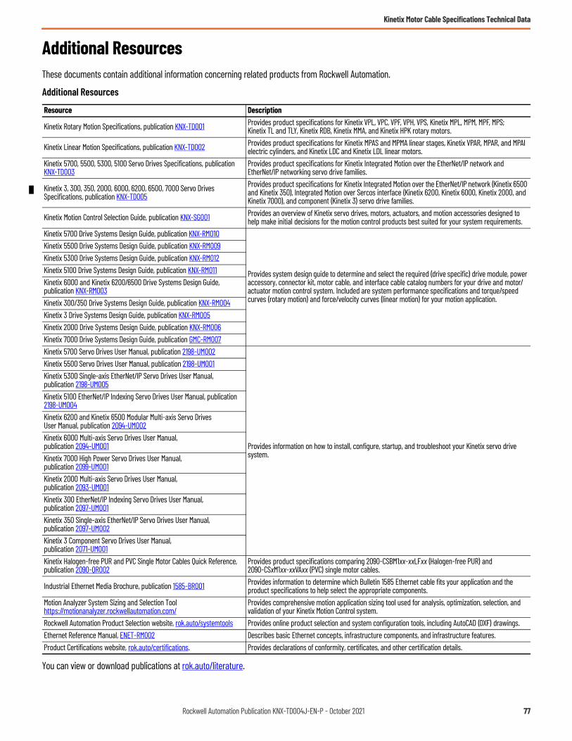
Rockwell Automation Publication KNX-TD004J-EN-P - October 2021 77
Kinetix Motor Cable Specifications Technical Data
Additional ResourcesThese documents contain additional information concerning related products from Rockwell Automation.
You can view or download publications at rok.auto/literature.
Additional Resources
Resource Description
Kinetix Rotary Motion Specifications, publication KNX-TD001 Provides product specifications for Kinetix VPL, VPC, VPF, VPH, VPS, Kinetix MPL, MPM, MPF, MPS; Kinetix TL and TLY, Kinetix RDB, Kinetix MMA, and Kinetix HPK rotary motors.
Kinetix Linear Motion Specifications, publication KNX-TD002 Provides product specifications for Kinetix MPAS and MPMA linear stages, Kinetix VPAR, MPAR, and MPAI electric cylinders, and Kinetix LDC and Kinetix LDL linear motors.
Kinetix 5700, 5500, 5300, 5100 Servo Drives Specifications, publication KNX-TD003
Provides product specifications for Kinetix Integrated Motion over the EtherNet/IP network and EtherNet/IP networking servo drive families.
Kinetix 3, 300, 350, 2000, 6000, 6200, 6500, 7000 Servo Drives Specifications, publication KNX-TD005
Provides product specifications for Kinetix Integrated Motion over the EtherNet/IP network (Kinetix 6500 and Kinetix 350), Integrated Motion over Sercos interface (Kinetix 6200, Kinetix 6000, Kinetix 2000, and Kinetix 7000), and component (Kinetix 3) servo drive families.
Kinetix Motion Control Selection Guide, publication KNX-SG001 Provides an overview of Kinetix servo drives, motors, actuators, and motion accessories designed to help make initial decisions for the motion control products best suited for your system requirements.
Kinetix 5700 Drive Systems Design Guide, publication KNX-RM010
Provides system design guide to determine and select the required (drive specific) drive module, power accessory, connector kit, motor cable, and interface cable catalog numbers for your drive and motor/actuator motion control system. Included are system performance specifications and torque/speed curves (rotary motion) and force/velocity curves (linear motion) for your motion application.
Kinetix 5500 Drive Systems Design Guide, publication KNX-RM009Kinetix 5300 Drive Systems Design Guide, publication KNX-RM012Kinetix 5100 Drive Systems Design Guide, publication KNX-RM011Kinetix 6000 and Kinetix 6200/6500 Drive Systems Design Guide, publication KNX-RM003Kinetix 300/350 Drive Systems Design Guide, publication KNX-RM004Kinetix 3 Drive Systems Design Guide, publication KNX-RM005Kinetix 2000 Drive Systems Design Guide, publication KNX-RM006Kinetix 7000 Drive Systems Design Guide, publication GMC-RM007Kinetix 5700 Servo Drives User Manual, publication 2198-UM002
Provides information on how to install, configure, startup, and troubleshoot your Kinetix servo drive system.
Kinetix 5500 Servo Drives User Manual, publication 2198-UM001Kinetix 5300 Single-axis EtherNet/IP Servo Drives User Manual, publication 2198-UM005Kinetix 5100 EtherNet/IP Indexing Servo Drives User Manual, publication 2198-UM004Kinetix 6200 and Kinetix 6500 Modular Multi-axis Servo Drives User Manual, publication 2094-UM002Kinetix 6000 Multi-axis Servo Drives User Manual, publication 2094-UM001Kinetix 7000 High Power Servo Drives User Manual,publication 2099-UM001Kinetix 2000 Multi-axis Servo Drives User Manual, publication 2093-UM001Kinetix 300 EtherNet/IP Indexing Servo Drives User Manual, publication 2097-UM001Kinetix 350 Single-axis EtherNet/IP Servo Drives User Manual, publication 2097-UM002Kinetix 3 Component Servo Drives User Manual, publication 2071-UM001Kinetix Halogen-free PUR and PVC Single Motor Cables Quick Reference, publication 2090-QR002
Provides product specifications comparing 2090-CSBM1xx-xxLFxx (Halogen-free PUR) and 2090-CSxM1xx-xxVAxx (PVC) single motor cables.
Industrial Ethernet Media Brochure, publication 1585-BR001 Provides information to determine which Bulletin 1585 Ethernet cable fits your application and the product specifications to help select the appropriate components.
Motion Analyzer System Sizing and Selection Toolhttps://motionanalyzer.rockwellautomation.com/
Provides comprehensive motion application sizing tool used for analysis, optimization, selection, and validation of your Kinetix Motion Control system.
Rockwell Automation Product Selection website, rok.auto/systemtools Provides online product selection and system configuration tools, including AutoCAD (DXF) drawings.Ethernet Reference Manual, ENET-RM002 Describes basic Ethernet concepts, infrastructure components, and infrastructure features.Product Certifications website, rok.auto/certifications. Provides declarations of conformity, certificates, and other certification details.

Publication KNX-TD004J-EN-P - October 2021Supersedes Publication KNX-TD004I-EN-P - December 2020 Copyright © 2021 Rockwell Automation, Inc. All rights reserved. Printed in the U.S.A.
Rockwell Automation SupportUse these resources to access support information.
Documentation FeedbackYour comments help us serve your documentation needs better. If you have any suggestions on how to improve our content, complete the form at rok.auto/docfeedback.
Technical Support Center Find help with how-to videos, FAQs, chat, user forums, and product notification updates. rok.auto/supportKnowledgebase Access Knowledgebase articles. rok.auto/knowledgebaseLocal Technical Support Phone Numbers Locate the telephone number for your country. rok.auto/phonesupportLiterature Library Find installation instructions, manuals, brochures, and technical data publications. rok.auto/literatureProduct Compatibility and Download Center (PCDC)
Download firmware, associated files (such as AOP, EDS, and DTM), and access product release notes. rok.auto/pcdc
Rockwell Automation maintains current product environmental compliance information on its website at rok.auto/pec.
Allen-Bradley, CompactLogix, ControlLogix, Encompass, expanding human possibility, Kinetix, Logix 5000, MicroLogix, On-Machine, PanelView, Rockwell Automation, RSLogix 5000, Stratix, and Studio 5000 Logix Designer are trademarks of Rockwell Automation, Inc.CIP Safety and EtherNet/IP are trademarks of ODVA, Inc.Trademarks not belonging to Rockwell Automation are property of their respective companies.
Rockwell Otomasyon Ticaret A.Ş. Kar Plaza İş Merkezi E Blok Kat:6 34752, İçerenköy, İstanbul, Tel: +90 (216) 5698400 EEE Yönetmeliğine Uygundur
Related Documents