Product Photo/Illustration GM29 Technical Description

Welcome message from author
This document is posted to help you gain knowledge. Please leave a comment to let me know what you think about it! Share it to your friends and learn new things together.
Transcript

Product Photo/Illustration
GM29Technical Description

The product described in this manual conforms to the Radio and Telecommunication Terminal Equipment (R&TTE) directive 99/5/EC with requirements covering EMC directive 89/336/EEC and Low Voltage directive 73/23/EEC. The product fulfils the requirements according to 3GPP TS 51.010-1, EN 301 489-7 and EN60950.
SAR statement: This product is intended to be used with the antenna or other radiating element at least 20cm away from any part of the human body.
The information contained in this document is the proprietary information of Sony Ericsson Mobile Communications International. The contents are confidential and any disclosure to persons other than the officers, employees, agents or subcontractors of the owner or licensee of this document, without the prior written consent of Sony Ericsson Mobile Communications International, is strictly prohibited. Further, no portion of this publication may be reproduced, stored in a retrieval system, or transmitted in any form or by any means, electronic or mechanical, including photocopying and recording, without the prior written consent of Sony Ericsson Mobile Communications International, the copyright holder.
First edition (June 2002)Sony Ericsson Mobile Communications International publishes this manual without making any warranty as to the content contained herein. Further Sony Ericsson Mobile Communications International reserves the right to make modifications, additions and deletions to this manual due to typographical errors, inaccurate information, or improvements to programs and/or equipment at any time and without notice. Such changes will, nevertheless be incorporated into new editions of this manual.
All rights reserved.© Sony Ericsson Mobile Communications International, 2002Publication number: LZT 123 7359 R1B
Printed in UK

Contents1. Introduction.............................................................................................................. 5
1.1 Description ..................................................................................................... 51.2 Highlights....................................................................................................... 51.3 Main Features and Services ........................................................................... 61.4 Service and Support ....................................................................................... 91.5 Precautions ..................................................................................................... 91.6 Abbreviations ................................................................................................. 9
2. Mechanical Description ......................................................................................... 112.1 Overview ...................................................................................................... 112.2 Physical Dimensions .................................................................................... 12
3. Electrical Description ............................................................................................ 133.1 Power Connector .......................................................................................... 133.2 Audio Connector .......................................................................................... 143.3 Antenna Connector....................................................................................... 163.4 SIM Card Reader.......................................................................................... 173.5 RS232 Serial Port ......................................................................................... 183.6 Real Time Clock .......................................................................................... 203.7 Software Updates ......................................................................................... 20
4. Operation ................................................................................................................ 214.1 Switching On the Modem ............................................................................ 214.2 Switching Off the Modem............................................................................ 214.3 Resetting the Modem ................................................................................... 214.4 Operating States/LED .................................................................................. 21
5. Technical Data........................................................................................................ 23
6. AT Command Summary ....................................................................................... 27
3LZT 123 7359 R1B
GM29 TECHNICAL DESCRIPTION
4LZT 123 7359 R1B

1. INTRODUCTION
1. Introduction
1.1 DescriptionThe dual band EGSM 900/1800MHz GM29 is a GSM/GPRS serial modem. The modem is a powerful and flexible device that can be used in a wide range of telemetry and telematics applications that rely on the remote exchange of data, voice, SMS or faxes via the GSM cellular network.
Small and lightweight, the GM29 has standard connectors and an integral SIM card reader making it easy and quick to integrate. As well as providing a standard RS232 serial communication interface the GM29 also has an audio interface allowing an analogue handset to be connected. When the GM29 is integrated into an external application, a wireless communicaions system is created.
A typical end-to-end system consists of a micro controller in an external application communicating, via the GM29 modem, with a remote terminal or host using the GSM network. The micro controller uses a set of AT commands to control the modem, and to set up the end-to-end communications link, via its 9-way RS232 serial interface.
GM29 serial modems are intended to be used by manufacturers, system integrators, application developers and developers of a wide range of equipment and business solutions, typically in the following fields:• Security and alarms• Vending • Monitoring and control• Utilities• Fleet Management
1.2 Highlights• Dual band, EGSM 900/1800MHz, GSM/GPRS serial modem• Flexible plug-and-play device• Data: GPRS, HSCSD, CSD, SMS• Voice: full rate, enhanced full rate, half rate• SMS: mobile-originated, mobile-terminated, cell broadcast• Fax: Group 3, Classes 1 & 2• RS232 9-way serial interface• 5V - 32V d.c. input• 4-wire audio connection• Antenna connection (FME male)• R&TTE type approved
5LZT 123 7359 R1B
GM29 TECHNICAL DESCRIPTION
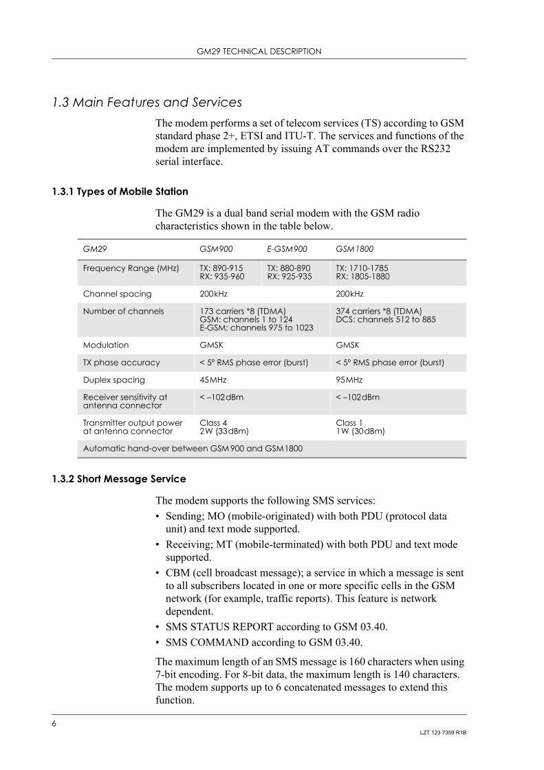
1.3 Main Features and ServicesThe modem performs a set of telecom services (TS) according to GSM standard phase 2+, ETSI and ITU-T. The services and functions of the modem are implemented by issuing AT commands over the RS232 serial interface.
1.3.1 Types of Mobile Station
The GM29 is a dual band serial modem with the GSM radio characteristics shown in the table below.
1.3.2 Short Message Service
The modem supports the following SMS services:• Sending; MO (mobile-originated) with both PDU (protocol data
unit) and text mode supported.• Receiving; MT (mobile-terminated) with both PDU and text mode
supported.• CBM (cell broadcast message); a service in which a message is sent
to all subscribers located in one or more specific cells in the GSM network (for example, traffic reports). This feature is network dependent.
• SMS STATUS REPORT according to GSM 03.40.• SMS COMMAND according to GSM 03.40.
The maximum length of an SMS message is 160 characters when using 7-bit encoding. For 8-bit data, the maximum length is 140 characters. The modem supports up to 6 concatenated messages to extend this function.
GM29 GSM900 E-GSM900 GSM1800
Frequency Range (MHz) TX: 890-915RX: 935-960
TX: 880-890RX: 925-935
TX: 1710-1785RX: 1805-1880
Channel spacing 200kHz 200kHz
Number of channels 173 carriers *8 (TDMA)GSM: channels 1 to 124E-GSM: channels 975 to 1023
374 carriers *8 (TDMA)DCS: channels 512 to 885
Modulation GMSK GMSK
TX phase accuracy < 5º RMS phase error (burst) < 5º RMS phase error (burst)
Duplex spacing 45MHz 95MHz
Receiver sensitivity at antenna connector
< –102dBm < –102dBm
Transmitter output power at antenna connector
Class 4 2W (33dBm)
Class 11W (30dBm)
Automatic hand-over between GSM 900 and GSM1800
6LZT 123 7359 R1B

1. INTRODUCTION
1.3.3 Voice Calls
The GM29 offers the capability of mobile originated and mobile terminated voice calls, as well as supporting emergency calls. Multi-party, call waiting and call deflection features are available. Some of these features are network-operator specific.
For the inter-connection of audio, the modem offers a balanced 4-wire analogue interface. The GM29 has embedded echo cancellation and noise suppression for improved audio quality.
DTMF (Dual Tone Multi Frequency) is supported.
1.3.4 Data
The modem supports the following data protocols:• GPRS (General Packet Radio Service).
Modems are Class B terminals, which provide simultaneous activation and attachment of GPRS and GSM services. GM29 modems are GPRS class 8 (4+1) enabled devices, which are capable of transmitting in one timeslot per frame (up link), and receiving at a maximum of four timeslots per frame (down link).
• CSD (Circuit Switched Data).GM29 modems are capable of establishing a CSD communication at 9.6kbps.
• HSCSD (High Speed Circuit Switched Data).GM29 supports HSCSD class 2 (2+1) communication, with one timeslot per frame capacity in the up link and two timeslots per frame capacity in the down link.
1.3.5 Fax
The GM29 allows fax transmissions to be sent and received by commercial fax software installed on the application computer. Group 3 fax Classes 1 and 2 are supported.
1.3.6 Supplementary Services
• Call forwarding• Call hold, waiting and multiparty• Calling/called number identification• Advice of charge• USSD• Alternate line service• Customer service profile• Preferred networks
7LZT 123 7359 R1B

GM29 TECHNICAL DESCRIPTION
• Operator selection• Network registration• Calling cards• Call barring• Call transfer
1.3.7 Serial Communication
The GM29 enables an end-to-end communication path to be established between the external telemetry/telematics application and a remote terminal or host, via the GSM network. Once a path has been set up, voice or data communication can take place. Serial data with flow control according to the RS232 signalling protocol operates between the modem and the external application.
Control of the GM29 is by the external application, via the RS232 serial interface, using a set of AT commands. The GM29 supports the full set of AT commands according to GSM 07.05 and GSM 07.07. It also supports an extended set of Ericsson proprietary AT commands to add extra functionality.
AT commands are used to operate the modem and have a broad range of functions including:• configuring general parameters of the GM29;• setting up and controlling communications to and from the GSM
network;• configuring the modem to communicate across the RS232 serial
interface;• and obtaining GSM network status information.
For more detail on the AT commands supported by the GM29 see “AT Command Summary”, page 27.
1.3.8 Interfacing with the GM29
The GM29 uses the following industry standard connectors to interface with the external application and the GSM network;• RJ11 (plug-in power supply connector)• RJ9 (handset audio connector)• Integral SIM card reader• FME male (antenna connector)• Sub-D socket, 9 pin (RS232 serial port)
8LZT 123 7359 R1B

1. INTRODUCTION
1.4 Service and SupportTo contact customer support please use the details below:
Customer SupportSony Ericsson Mobile CommunicationsMaplewood BuildingChineham Business ParkBasingstokeRG24 8YB
E-mail: [email protected]@sonyericsson.com
Information about Sony Ericsson and its products is available on the following web site:
http://www.sonyericsson.com/M2M
1.5 PrecautionsThe GM29 as a standalone item is designed for indoor use only. To use outside it must be integrated into a weatherproof enclosure. Do not exceed the environmental and electrical limits as specified in “Technical Data”, page 23.
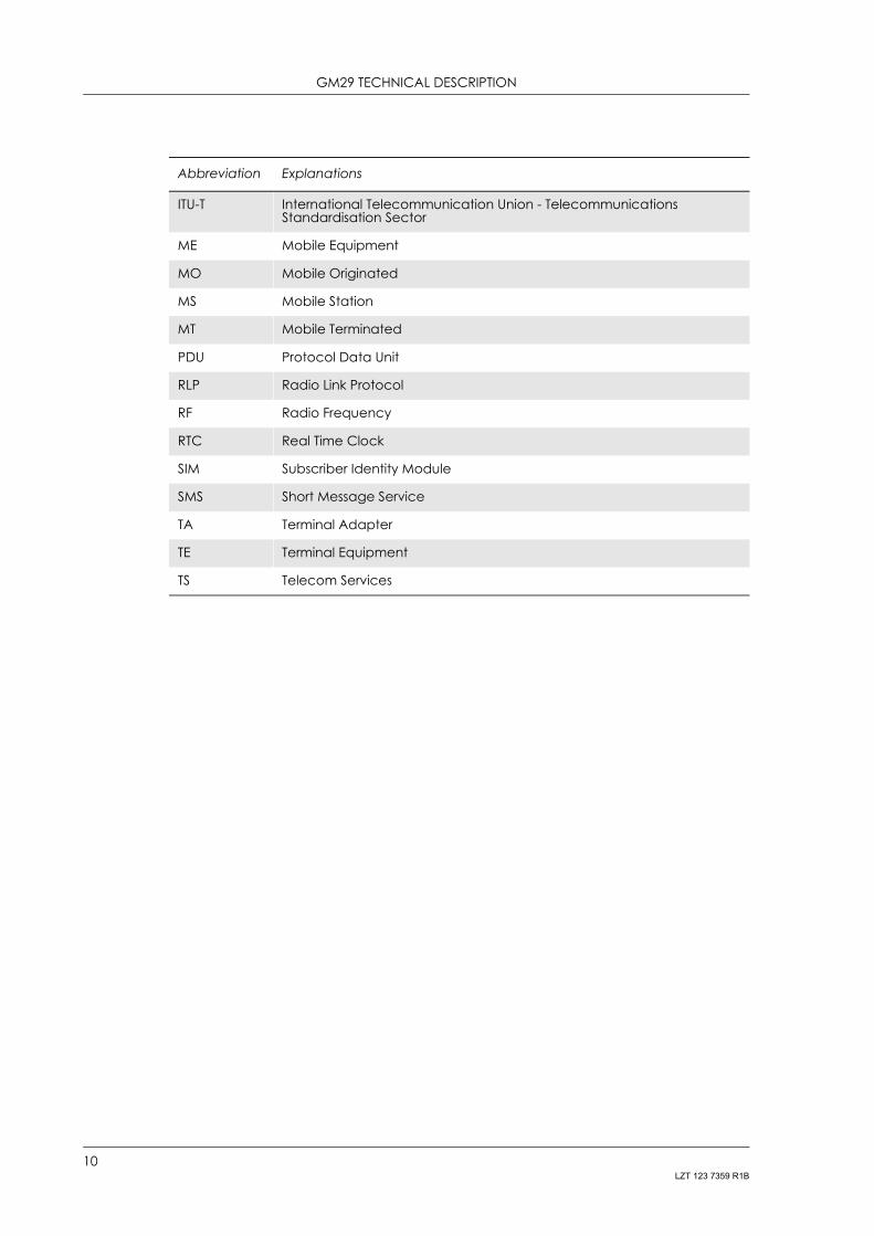
1.6 Abbreviations
Abbreviation Explanations
CBM Cell Broadcast Message
CBS Cell Broadcast Service
CSD Circuit Switched Data
DCE Data Circuit Terminating Equipment
DTE Data Terminal Equipment
DTMF Dual Tone Multi Frequency
EFR Enhanced Full Rate
EMC Electro-Magnetic Compatibility
ETSI European Telecommunication Standards Institute
FR Full Rate
GPRS General Packet Radio Service
GSM Global System for Mobile Communication
HR Half Rate
HSCSD High Speed Circuit Switched Data
9LZT 123 7359 R1B
GM29 TECHNICAL DESCRIPTION
ITU-T International Telecommunication Union - Telecommunications Standardisation Sector
ME Mobile Equipment
MO Mobile Originated
MS Mobile Station
MT Mobile Terminated
PDU Protocol Data Unit
RLP Radio Link Protocol
RF Radio Frequency
RTC Real Time Clock
SIM Subscriber Identity Module
SMS Short Message Service
TA Terminal Adapter
TE Terminal Equipment
TS Telecom Services
Abbreviation Explanations
10LZT 123 7359 R1B

2. MECHANICAL DESCRIPTION
2. Mechanical Description
2.1 OverviewThe pictures below show the mechanical design of the GM29 along with the positions of the different connectors and mounting holes. The GM29 case is made of durable PC/ABS plastic.
Figure 2.1 GM29 viewed from the left side
Figure 2.2 GM29 viewed from the right side
Antennaconnector
R 232 connectorS
LED
Access toSIM card
Mounting hole (x2)
Audioconnector
Powerconnector
11LZT 123 7359 R1B
GM29 TECHNICAL DESCRIPTION
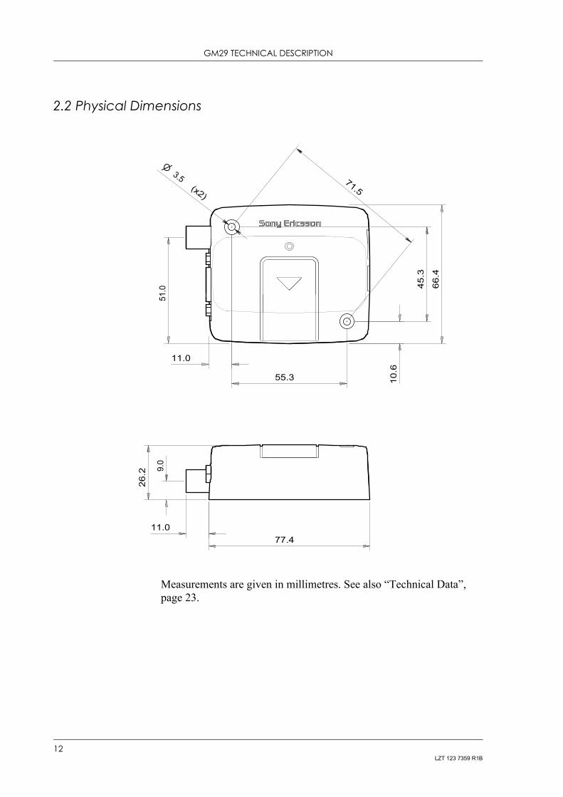
2.2 Physical Dimensions
Measurements are given in millimetres. See also “Technical Data”, page 23.
71.5
66.4
77.4
26.2
11.0
55.3
45.3
10.6
11.0
9.0
51.0
(x2)
3.5
12LZT 123 7359 R1B

3. ELECTRICAL DESCRIPTION
3. Electrical Description
All electrical connections to the GM29 are protected in compliance with the standard air (4kV) and contact (8kV) discharge ESD tests, of EN 301 489-1.
The modem uses the following industry standard connectors:• RJ11 6-way (power connector)• RJ9 4-way (handset connector)• SIM card reader• FME male coaxial jack (antenna connector)• Sub-D socket, 9 pin (RS232 serial port)
3.1 Power ConnectorAn RJ11 6-way connector, as shown and described below, serves as a means of supplying and controlling d.c. power to the modem.
The supply voltage,VCC, required by the modem is in the range 5V - 32V d.c. Application of the supply voltage does not switch the modem on. To do so an additional active-high control signal, TO_IN, must be applied for > 0.2s.
A second active-high control signal, HR_IN, can be used to switch the modem off when applied for 1 - 2 seconds, or can be used to perform a hardware reset when applied for > 3.5s.
TO_IN and HR_IN are referenced to GND (pin 6 on the connector).
VCC and GND are reverse polarity and overvoltage protected.
6 5 4 3 2 1
1 VCC2 n/c
3 HR_IN4 TO_IN
5 n/c6 GND
13LZT 123 7359 R1B
GM29 TECHNICAL DESCRIPTION
The power connector electrical characteristics are listed below:
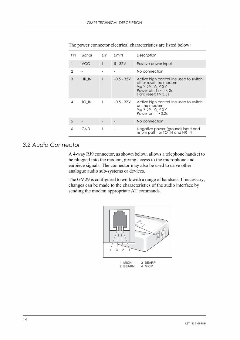
3.2 Audio ConnectorA 4-way RJ9 connector, as shown below, allows a telephone handset to be plugged into the modem, giving access to the microphone and earpiece signals. The connector may also be used to drive other analogue audio sub-systems or devices.
The GM29 is configured to work with a range of handsets. If necessary, changes can be made to the characteristics of the audio interface by sending the modem appropriate AT commands.
Pin Signal Dir Limits Description
1 VCC I 5 - 32V Positive power input
2 - - - No connection
3 HR_IN I –0.5 - 32V Active high control line used to switch off or reset the modemVIH > 5V, VIL < 2VPower off: 1s < t < 2sHard reset: t > 3.5s
4 TO_IN I –0.5 - 32V Active high control line used to switch on the modemVIH > 5V, VIL < 2VPower on: t > 0.2s
5 - - - No connection
6 GND I - Negative power (ground) input and return path for TO_IN and HR_IN
4 3 2 1
1 MICN2 BEARN
3 BEARP4 MICP
14LZT 123 7359 R1B

3. ELECTRICAL DESCRIPTION
Audio signal descriptions are listed below:
MICP and MICN are balanced differential microphone input signals. These inputs are compatible with an electret microphone.
BEARP and BEARN are the speaker output signals. These are differential-mode outputs. The electrical characteristics are given in the table below.
The following table shows the ear piece impedances that can be connected to BEARP and BEARN.
16 independent audio filters (8 transmit and 8 receive) determine the frequency/gain response characteristics of the audio interface. The gain characteristics of each of the Tx and Rx filters can be customised using AT commands to optimise and match the performance of the audio interface to a particular handset or audio sub-system.
The allowable range of the gain parameter for each RX and TX DSP filter is -11 to +9dB.
The factory default settings for the DSP filters provide optimised performance for the recommenced handset accessory.
Pin Signal Dir Description
1 MICN I Microphone negative input
2 BEARN O Earpiece negative output
3 BEARP O Earpiece positive output
4 MICP I Microphone positive input
Parameter Limit
Output level (differential) ≥4.0Vpp
Output level (dynamic load = 32Ω) ≥2.8Vpp
Distortion at 1kHz and maximum output level ≤5%
Offset, BEARP to BEARN ±30mV
Ear-piece mute-switch attenuation ≥40dB
Ear piece model Impedance Tolerance
Dynamic ear piece [32Ω + 800µH] // 100pF ±20%
Dynamic ear piece [150Ω + 800µH] // 100pF ±20%
Piezo ear piece 1kΩ + 60nF ±20%
15LZT 123 7359 R1B

GM29 TECHNICAL DESCRIPTION
3.3 Antenna ConnectorThe antenna connector allows transmission of radio frequency (RF) signals between the modem and an external customer-supplied antenna. The modem is fitted with a 50Ω, FME male coaxial jack as shown below.
The table below shows the antenna electrical characteristics:
Parameter Limit Description
Nominal impedance 50Ω (SWR better than 2.5:1)
Output Power2 Watt peak (Class 4) Extended GSM900
1 Watt peak (Class 1) GSM1800
Static SensitivityBetter than –102dBm Extended GSM900
Better than –102dBm GSM1800
GND
RF Signal
16LZT 123 7359 R1B

3. ELECTRICAL DESCRIPTION
3.4 SIM Card ReaderThe GM29 is fitted with a SIM card reader designed for 3V and 5V SIM cards. It is the flip-up type which is lockable in the horizontal position and is accessed through a removable panel as shown below.
17LZT 123 7359 R1B
GM29 TECHNICAL DESCRIPTION
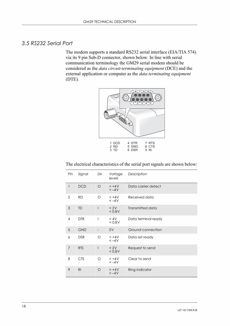
3.5 RS232 Serial PortThe modem supports a standard RS232 serial interface (EIA/TIA 574) via its 9 pin Sub-D connector, shown below. In line with serial communication terminology the GM29 serial modem should be considered as the data circuit-terminating equipment (DCE) and the external application or computer as the data terminating equipment (DTE).
The electrical characteristics of the serial port signals are shown below:
Pin Signal Dir Voltage levels
Description
1 DCD O > +4V< –4V
Data carrier detect
2 RD O > +4V< –4V
Received data
3 TD I > 2V< 0.8V
Transmitted data
4 DTR I > 4V< 0.8V
Data terminal ready
5 GND - 0V Ground connection
6 DSR O > +4V< –4V
Data set ready
7 RTS I > 2V< 0.8V
Request to send
8 CTS O > +4V< –4V
Clear to send
9 RI O > +4V< –4V
Ring indicator
9
1 DCD2 RD3 TD
4 DTR5 GND6 DSR
7 RTS8 CTS9 RI
76
54321
8
18LZT 123 7359 R1B
3. ELECTRICAL DESCRIPTION
3.5.1 Serial Data
The modem supports the standard data character format of 1 start bit, 8 bit data, no parity plus 1 stop bit, in total 10 bits per character.
3.5.2 Serial Data Signals - RD, TD
The default baud rate is 9.6kbps, however higher bit rates up to 460kbps are supported and can be set by AT commands. At start-up the GM29 transmits and receives data at the default rate of 9.6kbps in either standard AT mode or binary mode (the first received data - AT or binary format - determines the operating mode).
Serial Data From Modem (RD)
RD is an output signal that the modem uses to send data to the application.
Serial Data To Modem (TD)
TD is an input signal, used by the application to send data to the modem.
3.5.3 Control Signals - RTS, CTS, DTR, DSR, DCD, RI
RTS and CTS are capable of transmitting at 1/10th of the data transmission speed for data rates up to 460kbps (byte-oriented flow control mechanism).
Request to Send (RTS)
Used to condition the DCE for data transmission. The default level is high by internal pull up.
The exact behaviour of RTS is defined by an AT command. Software or hardware control can be selected. Hardware flow is the default control.
The application must pull RTS low to communicate with the modem. The modem will respond by asserting CTS low, indicating it is ready for communication.
Clear To Send (CTS)
CTS indicates that the DCE is ready to transmit data. The default level is high. You can define the exact behaviour of CTS through an AT command, and can select software or hardware flow control.
19LZT 123 7359 R1B

GM29 TECHNICAL DESCRIPTION
Data Terminal Ready (DTR)
DTR indicates that the DTE is ready to transmit and receive data. It also acts as a hardware ‘hang-up’, terminating calls when switched high. The signal is active low. You can define the exact behaviour of DTR with an AT command.
Data Set Ready (DSR)
An active DSR signal is sent from the modem to the application (DTE) to confirm that a communications path has been established. DSR has two modes of operation, settable using the AT command AT&S.
Data Carrier Detect (DCD)
DCD indicates that the DCE is receiving a valid carrier (data signal) when low. You can define the exact behaviour of DCD with an AT command.
Ring Indicator (RI)
RI indicates that a ringing signal is being received by the DCE when low. You can define the exact behaviour or RI with an AT command.
3.6 Real Time ClockThe GM29 contains a real time clock (RTC) to maintain accurate timekeeping and to enable “timestamping” of messages.
The RTC is powered all the time that the modem is turned on. When the modem is powered off, a stored energy device within the GM29 provides back-up power to maintain the RTC for at least 7 hours.
3.7 Software UpdatesIt is possible and sometimes necessary to update the GM29 software. Updates must be carried out by a Sony Ericsson approved technician. Please contact your supplier for details (see “Service and Support”, page 9).
20LZT 123 7359 R1B

4. OPERATION
4. Operation
4.1 Switching On the ModemThere are two ways to switch on the modem, once power is applied.• either assert TO_IN high for > 0.2s;• or activate the RS232 control line DTR, high for > 0.2s.
The modem is fully operational after 4 seconds. Logging onto a network may take longer than this and is outside the control of the modem.
The modem can be configured to start up at the time power is applied by permanently tying power connector signals TO_IN (pin 4) and VCC (pin 1) together. In this case DTR must be used to switch the modem on again after it has been switched off or reset, while power is still applied.
4.2 Switching Off the ModemThere are two ways to switch off the modem as described below:• either use the appropriate AT command;• or assert HR_IN high for 1 - 2 seconds. A delay of up to 10s is
experienced as the modem logs off the network.
4.3 Resetting the ModemA full system reset, independent of the status of the software, may be applied to the modem as follows:• assert HR_IN high for > 3.5s.
4.4 Operating States/LEDThe modem has a green LED, as depicted below, which is used to indicate various operating states. These states are described in following table.
LED
21LZT 123 7359 R1B

GM29 TECHNICAL DESCRIPTION
Operating state LED
After switching on the modem On after 4s
Switch off or power removed Off
Standby or talk Flashing
No network, network search, no SIM card, no PIN entered
On
22LZT 123 7359 R1B
5. TECHNICAL DATA
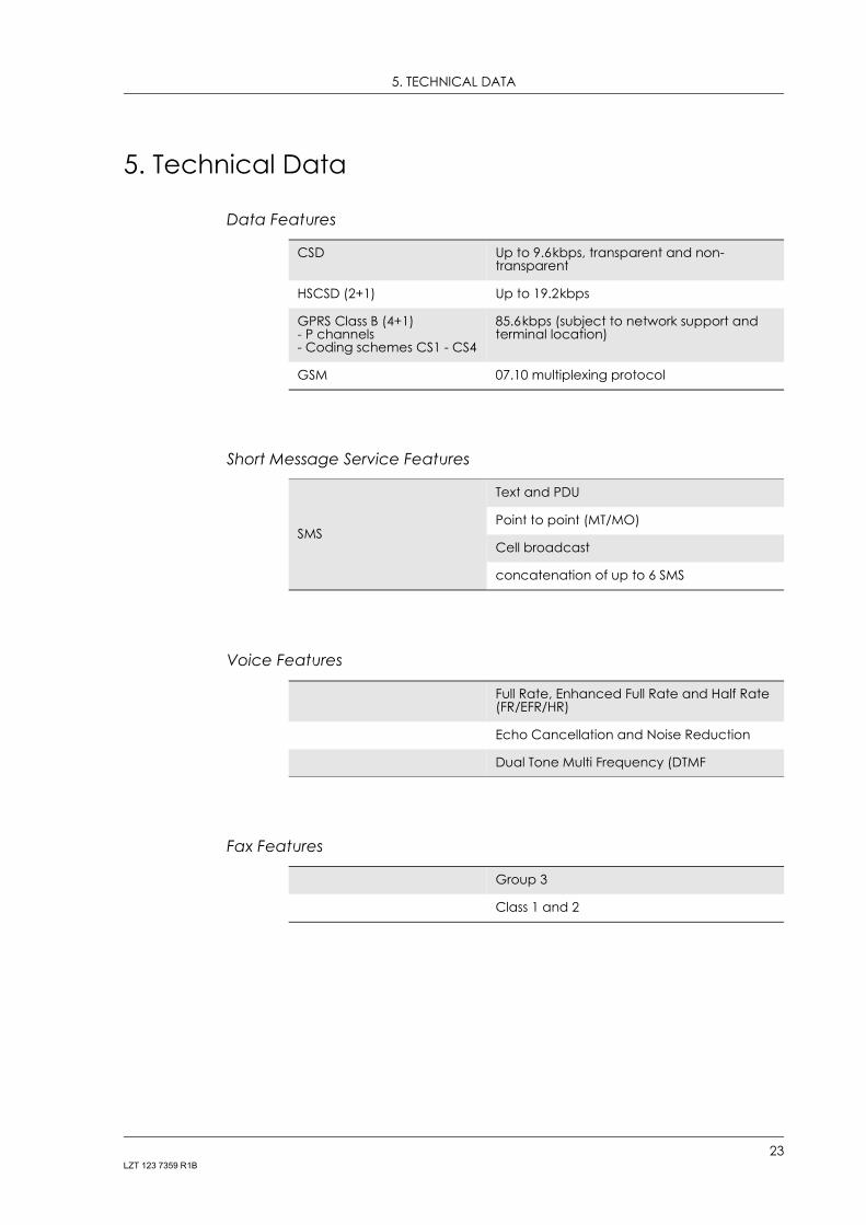
5. Technical Data
Data Features
Short Message Service Features
Voice Features
Fax Features
CSD Up to 9.6kbps, transparent and non-transparent
HSCSD (2+1) Up to 19.2kbps
GPRS Class B (4+1)- P channels- Coding schemes CS1 - CS4
85.6kbps (subject to network support and terminal location)
GSM 07.10 multiplexing protocol
SMS
Text and PDU
Point to point (MT/MO)
Cell broadcast
concatenation of up to 6 SMS
Full Rate, Enhanced Full Rate and Half Rate (FR/EFR/HR)
Echo Cancellation and Noise Reduction
Dual Tone Multi Frequency (DTMF
Group 3
Class 1 and 2
23LZT 123 7359 R1B

GM29 TECHNICAL DESCRIPTION
Data Storage
Power Supply
Average Power Consumption
Note! The power consumption during transmission is measured at maximum transmitted power.
Radio Specifications
SMS storage capacity 40 in ME
In addition, the unit can handle as many SMS as the SIM can store
Phone book capacity 100
Supply voltage range 5 - 32V d.c.
Idle Mode Transmit/Operation
GSM900Voice/CSD <15mA <250mA (<2A peak)
Data (GPRS 4+1) <15mA <350mA (<2A peak)
GSM1800Voice/CSD <15mA <250mA (<1.75A peak)
Data (GPRS 4+1) <15mA <350mA (<1.75A peak)
Frequency range GM29: EGSM 900MHz and 1800MHz (dual band)
Maximum RF output power
2W (900MHz) and 1W (1800MHz)
Antenna impedance 50Ω
Static sensitivity Better than –102dBm
24LZT 123 7359 R1B
5. TECHNICAL DATA
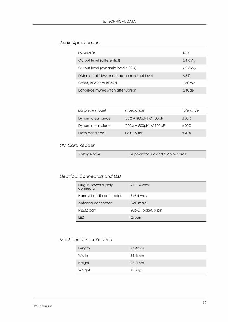
Audio Specifications
SIM Card Reader
Electrical Connectors and LED
Mechanical Specification
Parameter Limit
Output level (differential) ≥4.0Vpp
Output level (dynamic load = 32Ω) ≥2.8Vpp
Distortion at 1kHz and maximum output level ≤5%
Offset, BEARP to BEARN ±30mV
Ear-piece mute-switch attenuation ≥40dB
Ear piece model Impedance Tolerance
Dynamic ear piece [32Ω + 800µH] // 100pF ±20%
Dynamic ear piece [150Ω + 800µH] // 100pF ±20%
Piezo ear piece 1kΩ + 60nF ±20%
Voltage type Support for 3 V and 5 V SIM cards
Plug-in power supply connector
RJ11 6-way
Handset audio connector RJ9 4-way
Antenna connector FME male
RS232 port Sub-D socket, 9 pin
LED Green
Length 77.4mm
Width 66.4mm
Height 26.2mm
Weight <130g
25LZT 123 7359 R1B

GM29 TECHNICAL DESCRIPTION
Environmental specifications
Certification
Operating temperature range
–25°C to +55°C
Storage temperature range
–40°C to +85°C
Relative humidity 5 - 95%, non-condensing
Stationary vibration, sinusoidal
Displacement: 7.5mmAcceleration amplitude: 20m/s² and 40m/s²Frequency range: 2-8Hz, 8-200Hz, 200-500Hz
Stationary vibration, random
Acceleration spectral density (m²/s²): 0.96, 2.88, 0.96Frequency range:5-10Hz, 10-200Hz, 200-500Hz, 60min/axis
Non-stationary vibration, including shock
Shock response spectrum I, peak acceleration:3 shocks in each axis and direction;300m/s², 11msShock response spectrum II, peak acceleration:3 shocks in each axis and direction;1000m/s², 6ms
Bump Acceleration: 250m/s²
Free fall transportation 1.2m
Rolling pitching transportation
Angle: ±35degrees; period: 8s
Static load 10kPa
Low air pressure/high air pressure
70kPa/106kPa
Directive 1999/5/EC
EMC: EN 301 489-1
EMC: EN 301 489-7
Safety: EN 60950
GSM 3GPP TS 51.010-1
Tested according to GCF-CC
26LZT 123 7359 R1B

6. AT COMMAND SUMMARY
6. AT Command Summary
The AT standard is a line-oriented command language. AT is an abbreviation of ATtention and it is always used to start sending a command line from the terminal equipment (TE) to the terminal adaptor (TA).
The command line consists of a string of alphanumeric characters. It is sent to the modem to instruct it to perform the commands specified by the characters.
As the list of AT commands supported ocassionally changes, it is wise to check the latest listing with Sony Ericsson before starting any software development (see “Service and Support”, page 9).
Control and Identification
Call Control
Audio Control
Subscriber information AT+CNUM, AT+CIMI, AT*ESNU
Product and release information
AT+CGMI, AT+CGMM, AT+CGMR, AT+CGSN
Generic information and settings
AT, AT*, AT+CLAC, ATI, AT+CSCS, AT&F, AT&W, ATZ, AT+WS46, AT*E2SSN
Security and locks AT*E2SSD, AT*EPEE, AT+CPIN
Product functionality AT+CFUN
General call control ATA, ATD, ATL, ATH, ATP, ATT, ATX, AT+CHUP, AT+CMOD, AT+CVHU, AT+CR, AT+CRC
DTMF AT+VTS
Data commands ATO, AT+CRLP, AT*E2ESC
Audio profile modification AT*E2EAMS
Audio profile manipulation AT*EALR, AT*EAMS, AT*EARS, AT*ELAM, AT*EMIR, AT*EMIC, AT*EXVC, AT*E2APR
DSP filter settings AT*E2DSPRX, AT*E2DSPTX
27LZT 123 7359 R1B

GM29 TECHNICAL DESCRIPTION
Network Services
Settings
Short Message Service and Cell Broadcast
Alternate line service (ALS) AT*EALS, AT*ELIN, AT*ESLN
Customer service profile AT*ECSP
Call forwarding AT+CCFC, AT*EDIF
Calling/called number identification
AT+CLIP, AT+CLIR, AT*EIPS, AT+COLP
Preferred networks AT*EPNR, AT*EPNW
Advice of charge AT+CACM, AT+CAMM, AT+CAOC, AT+CPUC
Calling cards AT*ESCN
Call hold, waiting and multiparty
AT+CCWA, AT+CHLD
Operator selection AT+COPS
Network registration AT+CREG
USSD AT+CUSD, AT+CSSN, AT*E2SSI
Security and locks AT+CLCK, AT+CPWD, AT*ECPI
Service provider indication AT*E2SPN
Resetting AT*EMAR
ME status information AT*ECAM, AT+CSQ, AT+CIND, AT+CPAS, AT+CMER
Error control AT+CMEE, AT+CEER
Settings AT+CPMS, AT+CRES, AT+CSAS, AT+CSCA, AT+CSMS, AT+CNMI, AT+CSDH, AT+CSMP, AT+CGSMS
SMS command AT+CMGC
Read/write SMS AT+CMGD, AT+CMGW, AT+CMGL, AT+CMGR
Send SMS AT+CMGS, AT+CMSS
Format AT+CMGF
Broadcast message type AT+CSCB
28LZT 123 7359 R1B
6. AT COMMAND SUMMARY
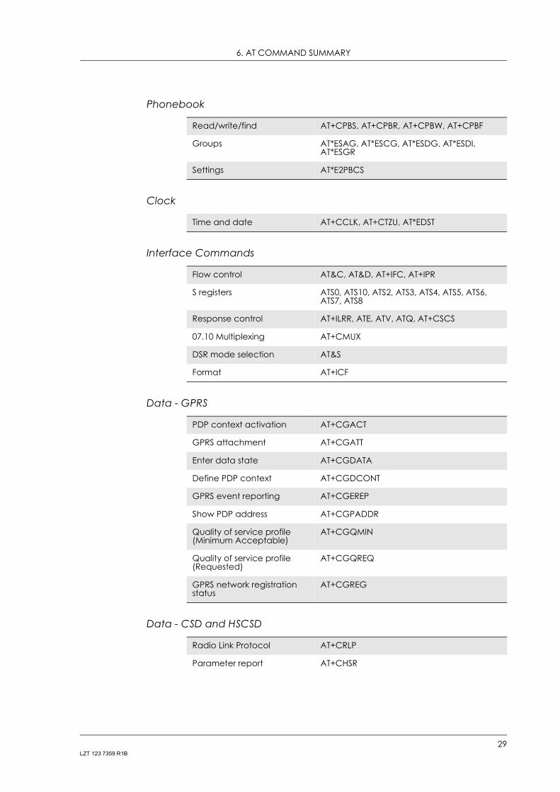
Phonebook
Clock
Interface Commands
Data - GPRS
Data - CSD and HSCSD
Read/write/find AT+CPBS, AT+CPBR, AT+CPBW, AT+CPBF
Groups AT*ESAG, AT*ESCG, AT*ESDG, AT*ESDI, AT*ESGR
Settings AT*E2PBCS
Time and date AT+CCLK, AT+CTZU, AT*EDST
Flow control AT&C, AT&D, AT+IFC, AT+IPR
S registers ATS0, ATS10, ATS2, ATS3, ATS4, ATS5, ATS6, ATS7, ATS8
Response control AT+ILRR, ATE, ATV, ATQ, AT+CSCS
07.10 Multiplexing AT+CMUX
DSR mode selection AT&S
Format AT+ICF
PDP context activation AT+CGACT
GPRS attachment AT+CGATT
Enter data state AT+CGDATA
Define PDP context AT+CGDCONT
GPRS event reporting AT+CGEREP
Show PDP address AT+CGPADDR
Quality of service profile (Minimum Acceptable)
AT+CGQMIN
Quality of service profile (Requested)
AT+CGQREQ
GPRS network registration status
AT+CGREG
Radio Link Protocol AT+CRLP
Parameter report AT+CHSR
29LZT 123 7359 R1B
GM29 TECHNICAL DESCRIPTION
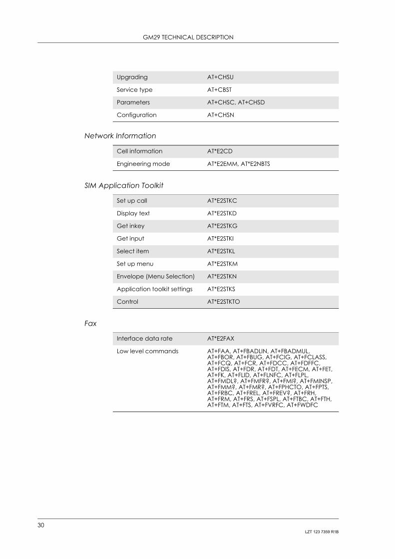
Network Information
SIM Application Toolkit
Fax
Upgrading AT+CHSU
Service type AT+CBST
Parameters AT+CHSC, AT+CHSD
Configuration AT+CHSN
Cell information AT*E2CD
Engineering mode AT*E2EMM, AT*E2NBTS
Set up call AT*E2STKC
Display text AT*E2STKD
Get inkey AT*E2STKG
Get input AT*E2STKI
Select item AT*E2STKL
Set up menu AT*E2STKM
Envelope (Menu Selection) AT*E2STKN
Application toolkit settings AT*E2STKS
Control AT*E2STKTO
Interface data rate AT*E2FAX
Low level commands AT+FAA, AT+FBADLIN, AT+FBADMUL, AT+FBOR, AT+FBUG, AT+FCIG, AT+FCLASS, AT+FCQ, AT+FCR, AT+FDCC, AT+FDFFC, AT+FDIS, AT+FDR, AT+FDT, AT+FECM, AT+FET, AT+FK, AT+FLID, AT+FLNFC, AT+FLPL, AT+FMDL?, AT+FMFR?, AT+FMI?, AT+FMINSP, AT+FMM?, AT+FMR?, AT+FPHCTO, AT+FPTS, AT+FRBC, AT+FREL, AT+FREV?, AT+FRH, AT+FRM, AT+FRS, AT+FSPL, AT+FTBC, AT+FTH, AT+FTM, AT+FTS, AT+FVRFC, AT+FWDFC
30LZT 123 7359 R1B
Related Documents