MANUAL GLYCOL-TYPE GAS DEHYDRATION AND HYDRATE INHIBITION SYSTEMS DEP 20.04.10.10-Gen. December 1994 (DEP Circulars 42/96, 16/99, 45/01, 57/03 and 15/04 have been incorporated) DESIGN AND ENGINEERING PRACTICE USED BY COMPANIES OF THE ROYAL DUTCH/SHELL GROUP This document is confidential. Neither the whole nor any part of this document may be disclosed to any third party without the prior written consent of Shell Internationale Petroleum Maatschappij B.V., The Hague, the Netherlands. The copyright of this document is vested in Shell Internationale Petroleum Maatschappij B.V., The Hague, the Netherlands. All rights reserved. Neither the whole nor any part of this document may be reproduced, stored in any retrieval system or transmitted in any form or by any means (electronic, mechanical, reprographic, recording or otherwise) without the prior written consent of the copyright owner.

Welcome message from author
This document is posted to help you gain knowledge. Please leave a comment to let me know what you think about it! Share it to your friends and learn new things together.
Transcript
MANUAL
GLYCOL-TYPE GAS DEHYDRATION AND HYDRATE INHIBITION SYSTEMS
DEP 20.04.10.10-Gen.
December 1994 (DEP Circulars 42/96, 16/99, 45/01, 57/03 and 15/04 have been incorporated)
DESIGN AND ENGINEERING PRACTICE
USED BY
COMPANIES OF THE ROYAL DUTCH/SHELL GROUP
This document is confidential. Neither the whole nor any part of this document may be disclosed to any third party without the prior written consent of Shell Internationale Petroleum Maatschappij B.V., The Hague, the Netherlands. The copyright of this document is vested in Shell Internationale Petroleum Maatschappij B.V., The Hague, the Netherlands. All rights reserved. Neither the whole nor any part of this document may be reproduced, stored in any retrieval system or transmitted in any form or by
any means (electronic, mechanical, reprographic, recording or otherwise) without the prior written consent of the copyright owner.
DEP 20.04.10.10-Gen. December 1994
Page 2
PREFACE DEPs (Design and Engineering Practice) publications reflect the views, at the time of publication, of:
Shell Global Solutions International B.V. (Shell GSI)
and
Shell International Exploration and Production B.V. (SIEP)
and
Shell International Chemicals B.V. (SIC)
and
other Service Companies.
They are based on the experience acquired during their involvement with the design, construction, operation and maintenance of processing units and facilities, and they are supplemented with the experience of Group Operating companies. Where appropriate they are based on, or reference is made to, international, regional, national and industry standards.
The objective is to set the recommended standard for good design and engineering practice applied by Group companies operating an oil refinery, gas handling installation, chemical plant, oil and gas production facility, or any other such facility, and thereby to achieve maximum technical and economic benefit from standardization.
The information set forth in these publications is provided to users for their consideration and decision to implement. This is of particular importance where DEPs may not cover every requirement or diversity of condition at each locality. The system of DEPs is expected to be sufficiently flexible to allow individual operating companies to adapt the information set forth in DEPs to their own environment and requirements.
When Contractors or Manufacturers/Suppliers use DEPs they shall be solely responsible for the quality of work and the attainment of the required design and engineering standards. In particular, for those requirements not specifically covered, the Principal will expect them to follow those design and engineering practices which will achieve the same level of integrity as reflected in the DEPs. If in doubt, the Contractor or Manufacturer/Supplier shall, without detracting from his own responsibility, consult the Principal or its technical advisor.
The right to use DEPs is granted by Shell GSI, SIEP or SIC, in most cases under Service Agreements primarily with companies of the Royal Dutch/Shell Group and other companies receiving technical advice and services from Shell GSI, SIEP, SIC or another Group Service Company. Consequently, three categories of users of DEPs can be distinguished:
1) Operating companies having a Service Agreement with Shell GSI, SIEP, SIC or other Service Company. The use of DEPs by these operating companies is subject in all respects to the terms and conditions of the relevant Service Agreement.
2) Other parties who are authorized to use DEPs subject to appropriate contractual arrangements (whether as part of a Service Agreement or otherwise).
3) Contractors/subcontractors and Manufacturers/Suppliers under a contract with users referred to under 1) or 2) which requires that tenders for projects, materials supplied or - generally - work performed on behalf of the said users comply with the relevant standards.
Subject to any particular terms and conditions as may be set forth in specific agreements with users, Shell GSI, SIEP and SIC disclaim any liability of whatsoever nature for any damage (including injury or death) suffered by any company or person whomsoever as a result of or in connection with the use, application or implementation of any DEP, combination of DEPs or any part thereof, even if it is wholly or partly caused by negligence on the part of Shell GSI, SIEP or other Service Company. The benefit of this disclaimer shall inure in all respects to Shell GSI, SIEP, SIC and/or any company affiliated to these companies that may issue DEPs or require the use of DEPs.
Without prejudice to any specific terms in respect of confidentiality under relevant contractual arrangements, DEPs shall not, without the prior written consent of Shell GSI and SIEP, be disclosed by users to any company or person whomsoever and the DEPs shall be used exclusively for the purpose for which they have been provided to the user. They shall be returned after use, including any copies which shall only be made by users with the express prior written consent of Shell GSI, SIEP or SIC. The copyright of DEPs vests in Shell GSI and SIEP. Users shall arrange for DEPs to be held in safe custody and Shell GSI, SIEP or SIC may at any time require information satisfactory to them in order to ascertain how users implement this requirement.
All administrative queries should be directed to the DEP Administrator in Shell GSI.
DEP 20.04.10.10-Gen. December 1994
Page 3
TABLE OF CONTENTS 1 INTRODUCTION ........................................................................................................5 1.1 SCOPE........................................................................................................................5 1.2 DISTRIBUTION, APPLICABILITY AND REGULATORY CONSIDERATIONS ..........6 1.3 DEFINITIONS .............................................................................................................7 1.4 SYMBOLS AND ABBREVIATIONS..........................................................................11 1.5 CROSS-REFERENCES ...........................................................................................15 2 PROCESS DESCRIPTION OF GAS DEHYDRATION ............................................16 2.1 BASIC FLOW SCHEME ...........................................................................................18 2.2 COLDFINGER...........................................................................................................20 2.3 VACUUM...................................................................................................................21 2.4 GAS STRIPPING ......................................................................................................22 2.5 AZEOTROPIC STRIPPING ......................................................................................23 2.6 ACID GAS SOLUBILITIES AND STRIPPING ..........................................................24 2.7 DEHYDRATION OF CO2..........................................................................................25 2.8 MERCURY IN THE FEED GAS................................................................................27 2.9 PROCESS VARIABLES ...........................................................................................28 3 DESIGN GUIDELINES FOR GAS DEHYDRATION SYSTEMS..............................30 3.1 INLET GAS COOLER ...............................................................................................31 3.2 INLET GAS SEPARATOR........................................................................................32 3.3 CONTACTOR ...........................................................................................................33 3.4 GLYCOL REGENERATOR.......................................................................................41 3.5 HEAT EXCHANGERS ..............................................................................................49 3.6 SURGE DRUM .........................................................................................................54 3.7 GLYCOL FLASH VESSEL........................................................................................55 3.8 CONDENSED OVERHEADS SEPARATOR............................................................56 3.9 FILTERS ...................................................................................................................57 3.10 GLYCOL CIRCULATION PUMPS ............................................................................59 3.11 PIPING, VALVES AND FITTINGS............................................................................60 3.12 COLDFINGER...........................................................................................................62 3.13 GAS STRIPPING ......................................................................................................63 3.14 AZEOTROPIC STRIPPING (DRIZO) .......................................................................65 3.15 ELECTRICAL REQUIREMENTS..............................................................................66 3.16 MECHANICAL REQUIREMENTS ............................................................................67 4 UPGRADING OF GAS DEHYDRATION SYSTEMS ...............................................69 4.1 INLET SEPARATION................................................................................................69 4.2 CONTACTOR ...........................................................................................................69 4.3 GLYCOL REGENERATION CIRCUIT......................................................................70 5 OPERATION AND MAINTENANCE OF GLYCOL DEHYDRATION SYSTEMS ....71 5.1 PERFORMANCE CONSIDERATIONS ....................................................................71 5.2 OPERATING PROBLEMS........................................................................................74 5.3 START-UP AND SHUT-DOWN PROCEDURES .....................................................75 5.4 MAINTENANCE........................................................................................................75 6 DESCRIPTION OF PROCESSES FOR HYDRATE INHIBITION ............................76 6.1 FLOW SCHEME FOR AN LTS PROCESS WITH EXPANSION VALVE .................77 6.2 FLOW SCHEME FOR AN LTS PROCESS WITH MECHANICAL
REFRIGERATION ....................................................................................................77 6.3 FLOW SCHEME FOR LTS PROCESS WITH TURBO-EXPANDER .......................77 6.4 FLOW SCHEME FOR A WET GAS PIPELINE ........................................................78 6.5 FLOW SCHEME FOR GLYCOL REGENERATION.................................................78 7 DESIGN GUIDELINES FOR HYDRATE INHIBITION SYSTEMS ...........................79 7.1 INJECTION SYSTEMS.............................................................................................79 7.2 COLD LIQUID HEATERS .........................................................................................81 7.3 CONDENSATE/GLYCOL SEPARATION.................................................................81 7.4 GLYCOL REGENERATION......................................................................................83
DEP 20.04.10.10-Gen. December 1994
Page 4
7.5 PARTICLE FILTERS.................................................................................................83 7.6 GLYCOL PUMP FOR COLD LIQUID PRE-HEATER...............................................84 7.7 GLYCOL STORAGE.................................................................................................84 8 UPGRADING OF HYDRATE INHIBITION SYSTEMS.............................................85 8.1 INLET SEPARATION................................................................................................85 8.2 INJECTION SYSTEM ...............................................................................................85 8.3 TYPE OF GLYCOL ...................................................................................................85 9 OPERATIONS AND MAINTENANCE OF HYDRATE INHIBITION SYSTEMS ......86 9.1 GLYCOL SOLUTION PROBLEMS...........................................................................86 9.2 HYDRATE BLOCKAGE ............................................................................................86 9.3 GLYCOL LOSSES ....................................................................................................87 10 PROCESS CONTROL AND SAFEGUARDING ......................................................88 10.1 GLYCOL CONTACTOR............................................................................................88 10.2 FLASH VESSEL .......................................................................................................89 10.3 REGENERATOR ......................................................................................................89 10.4 ALARMS AND INDICATIONS ..................................................................................90 10.5 PROCESS SAFEGUARDING...................................................................................91 11 REFERENCES .........................................................................................................92 12 BIBLIOGRAPHY ......................................................................................................95 FIGURES ..................................................................................................................................96
APPENDICES APPENDIX I PROPERTIES OF GLYCOLS .......................................................................138 APPENDIX II GLYCOL FOAM CONTROL TEST................................................................148 APPENDIX III TESTING OF GLYCOL QUALITY .................................................................150 APPENDIX IV EVALUATING THE RESULTS OF GLYCOL SAMPLE TESTING................151 APPENDIX V TROUBLESHOOTING GAS DEHYDRATION SYSTEMS ............................153 APPENDIX VI START-UP AND SHUT-DOWN PROCEDURES FOR GAS
DEHYDRATION SYSTEMS ..........................................................................155 APPENDIX VII MAINTENANCE OF GAS DEHYDRATION SYSTEMS ................................158
DEP 20.04.10.10-Gen. December 1994
Page 5
1 INTRODUCTION
1.1 SCOPE
This is a new DEP which gives guidance and procedures for the design, material selection, fabrication, operation and maintenance of glycol-type gas dehydration and hydrate inhibition systems for:
- onshore and offshore locations; - sweet and sour service; - operating temperatures above -40 °C.
Gas dehydration and hydrate inhibition, based primarily on TEG and MEG respectively, are addressed in this DEP because of the many areas of commonality. Sections on gas dehydration precede those on hydrate inhibition with only the latter containing cross-references.
There is only one industry standard which partly covers the scope of this DEP, i.e. API specification 12GDU for (onshore) Glycol-Type Gas Dehydration Units. Since its approach and recommendations often conflict with this manual, leaving few areas of agreement, it is not further referenced and therefore should not be used.
This DEP discusses the merits of and offers design guidelines for different dehydration processes. It is beyond the scope of this DEP to give specific recommendations for selection of a particular process.
DEP 20.04.10.10-Gen. December 1994
Page 6
1.2 DISTRIBUTION, APPLICABILITY AND REGULATORY CONSIDERATIONS
Unless otherwise authorised by SIPM, the distribution of this DEP is confined to companies forming part of, or managed by, the Royal Dutch/Shell Group, and to Contractors nominated by them (i.e. the distribution code is "C" as defined in DEP 00.00.05.05-Gen.).
This DEP is intended for use in associated and non-associated gas production and treatment facilities.
If national and/or local regulations exist in which some of the requirements are more stringent than in this DEP the Contractor shall determine by careful scrutiny which of the requirements are the more stringent and which combination of requirements will be acceptable as regards safety, economic and legal aspects. In all cases the Contractor shall inform the Principal of any deviation from the requirements of this DEP which is considered to be necessary in order to comply with national and/or local regulations. The Principal may then negotiate with the Authorities concerned with the object of obtaining agreement to follow this DEP as closely as possible.
DEP 20.04.10.10-Gen. December 1994
Page 7
1.3 DEFINITIONS
1.3.1 General definitions The Contractor is the party which carries out all or part of the design, engineering, procurement, construction, commissioning or management of a project or operation of a facility. The Principal may undertake all or part of the duties of the Contractor.
The Manufacturer/Supplier is the party which manufactures or supplies equipment and services to perform the duties specified by the Contractor.
The Principal is the party which initiates the project and ultimately pays for its design and construction. The Principal will generally specify the technical requirements. The Principal may also include an agent or consultant authorised to act for, and on behalf of, the Principal.
The word shall indicates a requirement.
The word should indicates a recommendation.
1.3.2 Specific definitions Absorber See contactor Absorption Process The attraction and retention of vapours (water) by
liquids (glycol) from a gas stream. Actual Trays The number of trays installed in a column or the
equivalent number of actual trays for a packed column.
Bubble Cap Tray Horizontal plate holding bubble caps and
downcomers in the contactor. Bubble Caps Slotted metal caps attached over elevated nozzles
(risers) on the bubble cap trays. The slots cause the gas to break up into small bubbles for intimate contact with the glycol.
Condensate Light hydrocarbon liquids. Contactor (or Absorber) A vertical pressure vessel where gas and glycol
are intermingled counter-currently to remove water vapour from the gas. The contactor usually contains bubble cap trays, valve trays or structured packing.
Dehydration Removal of water vapour from a gas. Design Pressure The pressure used in the design of a vessel for
the purpose of determining the minimum permissible wall thickness or physical characteristics of the different parts of the vessel.
Dewpoint The temperature at which vapour begins to
condense into a liquid at a particular system pressure. A natural gas stream exhibits both hydrocarbon and water dewpoints.
Dewpoint Depression The difference in water dewpoint temperature
between the gas entering and leaving the
DEP 20.04.10.10-Gen. December 1994
Page 8
contactor. Downcomer The vertical conduit between trays which allows
liquid to pass from tray to tray. Flood The condition wherein excess liquid hold-up
occurs and normal counterflow action is prevented in the glycol contactor, regeneration still or stripping column. It is a design limit which when reached in operation causes an excessive loss of liquid from the top of the column.
Free Water Liquid water which is not dissolved in any other
substance. Gas/Glycol Heat Exchanger A heat exchanger employed to cool the lean
glycol by the gas leaving the contactor before the glycol enters the contactor.
Glycol A hygroscopic liquid. Mono-ethylene Glycol
(MEG) and Di-ethylene Glycol (DEG) are commonly used in hydrate inhibition service and Tri-ethylene Glycol (TEG) is most common in gas dehydration service.
Lean Glycol (or Dry Glycol) Glycol which has been regenerated and has a low
water content. Rich Glycol (or Wet Glycol) Glycol which has absorbed water and thus has a
high water content. Glycol Flash Separator A two or three phase separator which is used in
the rich glycol stream to remove entrained gas and hydrocarbon liquids.
Glycol/Glycol Exchanger A heat exchanger employed to recover heat from
the outgoing hot lean glycol from the reboiler and for pre-heating the incoming cool rich glycol from the contactor.
Heat Duty The rate of heat absorption by the process. Heat Flux The average heat transfer rate through the heat
exchanger tube, to the fluid. Hydrate A clathrate compound formed by a combination of
methane, ethane, propane, iso-butane, H2S or CO2 and free water at elevated pressure and low temperature.
Hydrate Inhibitor A chemical (e.g. glycol, methanol) which
depresses the hydrate formation temperature. Hydrate Temperature The highest temperature at which hydrates can
form in the presence of gas and free water at a given pressure.
Inlet Gas Separator (Scrubber)
A separator which removes free liquids from the inlet gas stream. The separator may be separate
DEP 20.04.10.10-Gen. December 1994
Page 9
from or integral with the contactor. Liquid Seal A liquid column in the downcomer that forces the
gas to pass up through the trays rather than up the downcomer.
Packing Material installed in the contactor, still column or
stripping column that provides a large surface area for intermingling liquid and vapour to facilitate mass transfer during absorption, distillation or stripping. Random packing consists of shaped pieces (e.g. rings, saddles) that have been dumped, not stacked, in the column. Structured packing is essentially a series of parallel formed metal sheets.
pH Measure of the acidity of a liquid on a scale of 0 to
14 with 7 being neutral. 0 to 7 is acidic and 7 to 14 is alkaline.
Reboiler A vessel for boiling water out of the glycol. Regenerator A unit including reboiler, still column and other
related facilities to regenerate (or re-concentrate) rich glycol to lean glycol.
Reflux Condensed liquid which flows back down a
column to maximise separation efficiency. Saturated Gas (with respect to water)
A gas stream which contains the maximum amount of water vapour at a given temperature and pressure without condensing the water.
Sour Service Sour conditions as defined in
DEP 31.22.10.32-Gen. Sparging Tube Internal pipe in the reboiler used to distribute
stripping gas. Standard (pressure and temperature)
Unit of gas volume at reference conditions of 101.3 kPa and 15 °C. Abbreviated: m3(st).
Still Reflux Column Vertically mounted distillation (fractionation)
column on top of the reboiler. Stripping Column A packed column where glycol from the reboiler
flows downward to the surge drum (see Figure 2.1) while gas flows upward stripping the glycol of water.
Stripping Gas Gas that is contacted with glycol to help remove
water from the glycol. Surge Drum Reservoir for regenerated glycol which may be
integral with, or separate from, the reboiler. Sweet Service Where the partial pressure of H2S is less than
0.34 kPa.
DEP 20.04.10.10-Gen. December 1994
Page 10
Swirltube A high capacity cyclone type contacting device. A number of tubes may be assembled on a deck or tray for gas/liquid separation (de-misting) or glycol contacting.
Theoretical Tray One in which the vapour and liquid leaving the
stage are in equilibrium. The number of actual trays is equal to the number of theoretical trays divided by the overall tray efficiency.
Transfer Unit The dimensionless distance within which every
solute molecule has "unit opportunity" to transfer to the gas phase. A transfer unit can be calculated for a theoretical stage.
Tray Efficiency The ratio between the number of theoretical and actual trays.
Valve Tray Horizontal plate holding valves and downcomers
in the contactor. A valve consists of a liftable metal plate which covers a hole in the tray, providing a variable area for gas flow.
DEP 20.04.10.10-Gen. December 1994
Page 11
1.4 SYMBOLS AND ABBREVIATIONS
A Area m2 AF Antifoaming agent As Specific area of packing m2/m3 BTEX Aromatic components: benzene, toluene, ethylbenzene
and xylene -
D Inside diameter of column or vessel m DEG Diethylene glycol - d Nozzle inside diameter, or diameter (with subscript) m F Packing factor m-1 FCV Flow control valve - FF Fraction of flood - g Acceleration due to gravity 9.81 m/s2 G Gas mass flowrate/unit area kg/(s.m2) GTD Greater temperature difference °C h Height m H Packing height m HC Height of channel or riser height of distributor m HETP Height equivalent to a theoretical plate m HIC Hydrogen-induced cracking - HOW Height of liquid crest over weir or liquid above drip hole mm HPSD High pressure shut-down - HTU Height of transfer unit m IL Interface level of condensate and glycol - L Length of vessel between tangent lines m LA (H) High level pre-alarm LA (L) Low level pre-alarm LCV Level control valve - LP Low pressure -
DEP 20.04.10.10-Gen. December 1994
Page 12
LTD Lower temperature difference °C LTS Low temperature separation process - LZA (HH) High level trip - LZA (LL) Low level trip - m Mass flowrate kg/s MEA Methylethanol amine - MEG Monoethylene glycol - MTD Mean temperature difference °C N Number of bubble cap or swirltube trays - NL Normal level of liquid - NOx Nitric oxide (NO), Nitrogen dioxide (NO2) and Nitrous
oxide (N2O) -
NPSH Net positive suction head m NTU Number of transfer units - OVHD Overhead - P Pressure Pa PCV Pressure control valve - PSV Safety relief valve - Q Volumetric flow rate m3/s q Heat duty kJ/litre Re Reynold's number - SMIRK Shell modified and improved Redlich Kwong SRKM Soave Redlich Kwong (modified) SMS Schoepentoeter - mist mat - swirldeck separator T Temperature °C, K TCV Temperature control valve - TEG Triethylene glycol - TREG Tetraethylene glycol - TS Tray spacing in contactor m TTL Top tangent line on vessel -
DEP 20.04.10.10-Gen. December 1994
Page 13
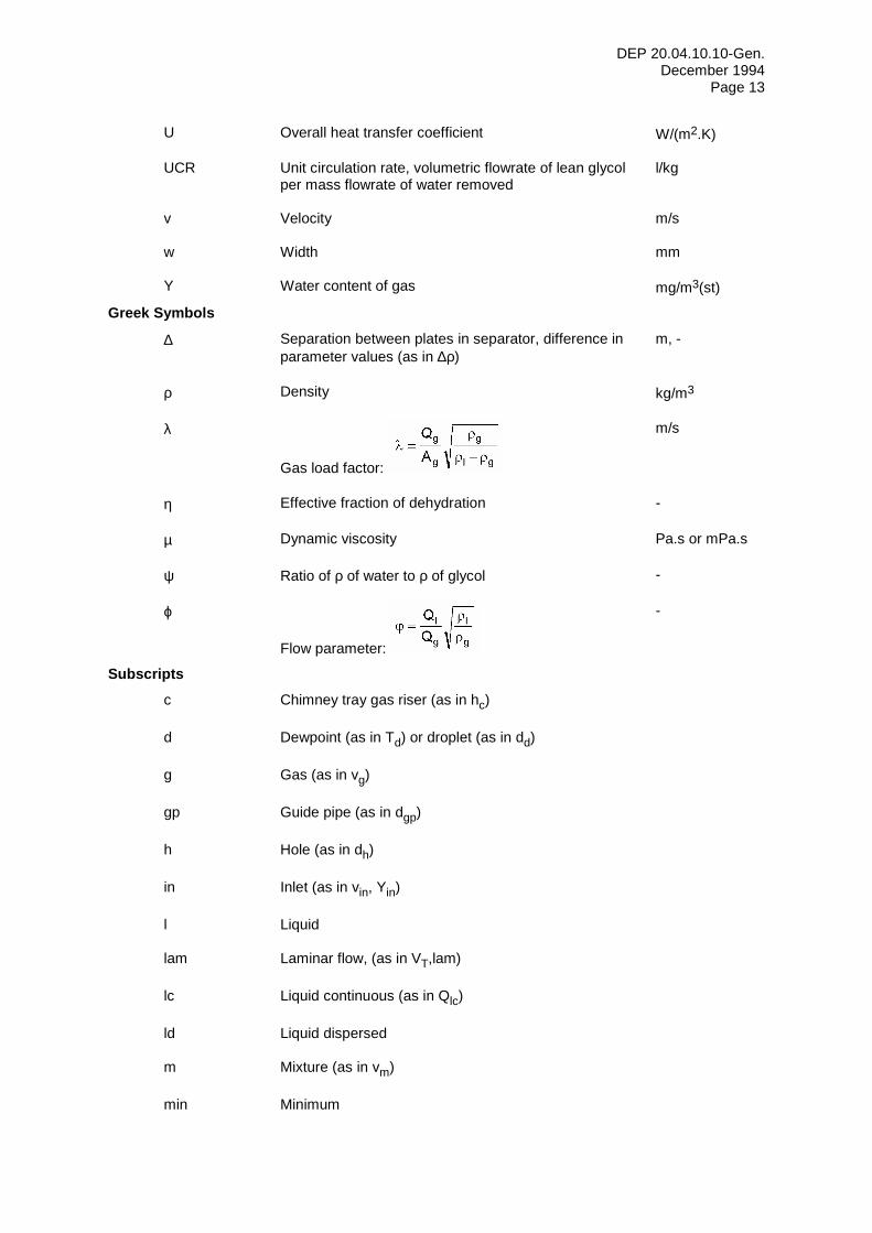
U Overall heat transfer coefficient W/(m2.K) UCR Unit circulation rate, volumetric flowrate of lean glycol
per mass flowrate of water removed l/kg
v Velocity m/s w Width mm Y Water content of gas mg/m3(st)
Greek Symbols
∆ Separation between plates in separator, difference in parameter values (as in ∆ρ)
m, -
ρ Density kg/m3 λ
Gas load factor:
m/s
η Effective fraction of dehydration - µ Dynamic viscosity Pa.s or mPa.s ψ Ratio of ρ of water to ρ of glycol - ϕ
Flow parameter:
-
Subscripts c Chimney tray gas riser (as in hc) d Dewpoint (as in Td) or droplet (as in dd) g Gas (as in vg) gp Guide pipe (as in dgp) h Hole (as in dh) in Inlet (as in vin, Yin) l Liquid lam Laminar flow, (as in VT,lam) lc Liquid continuous (as in Qlc) ld Liquid dispersed m Mixture (as in vm) min Minimum
DEP 20.04.10.10-Gen. December 1994
Page 14
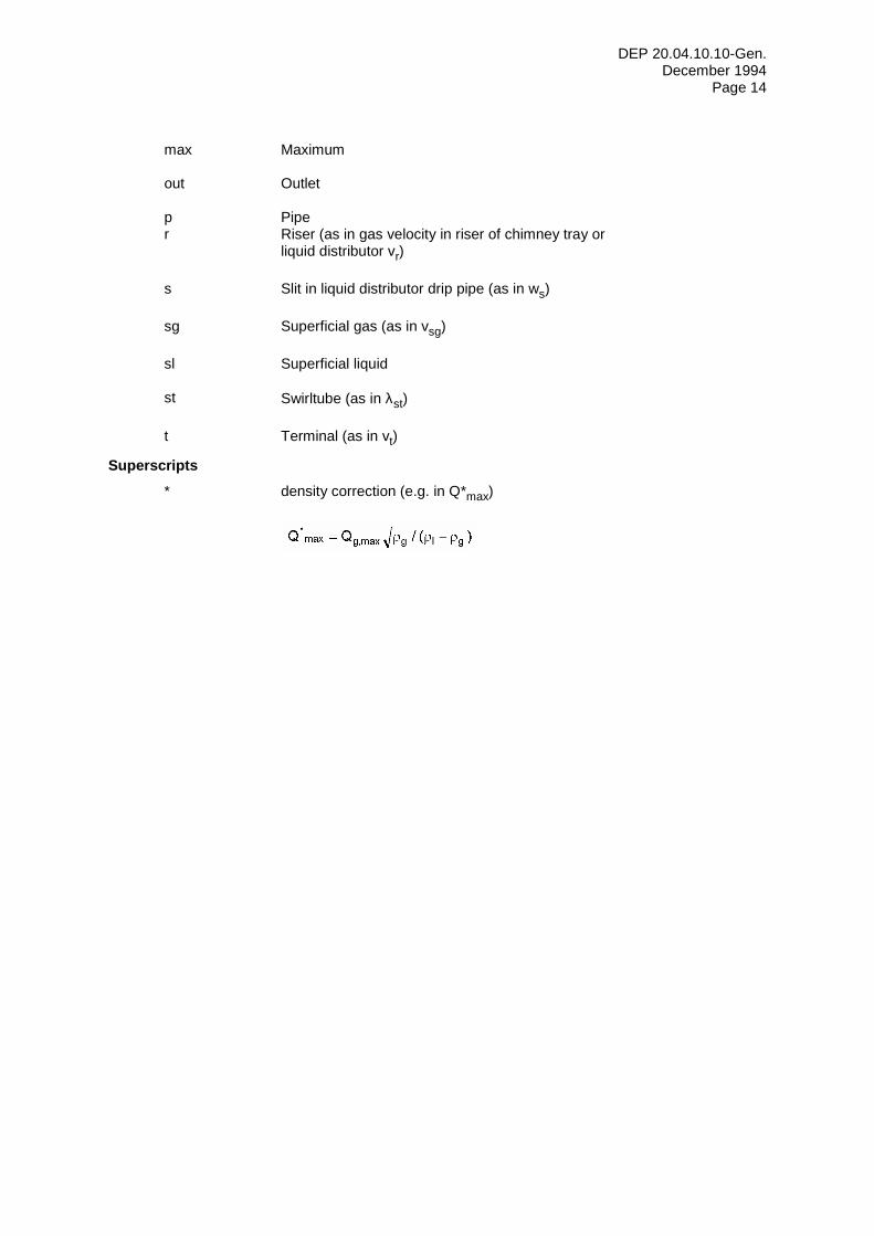
max Maximum out Outlet p Pipe r Riser (as in gas velocity in riser of chimney tray or
liquid distributor vr)
s Slit in liquid distributor drip pipe (as in ws) sg Superficial gas (as in vsg) sl Superficial liquid st Swirltube (as in λst) t Terminal (as in vt)
Superscripts * density correction (e.g. in Q*max)

DEP 20.04.10.10-Gen. December 1994
Page 15
1.5 CROSS-REFERENCES
Where cross-references to other parts of this DEP are made, the referenced section number is shown in brackets. Other documents referenced in this DEP are listed in (11).
DEP 20.04.10.10-Gen. December 1994
Page 16
2 PROCESS DESCRIPTION OF GAS DEHYDRATION The principle of glycol dehydration is contacting a gas stream with a hygroscopic liquid which has a greater affinity for the water vapour than does the gas. Contactor pressure is subject to economic evaluation usually influenced by water removal duty, required water dewpoint, vessel diameter and wall thickness. After contacting the gas, the water-rich glycol is regenerated by heating at approximately atmospheric pressure to a temperature high enough to drive off virtually all the absorbed water. The regenerated glycol is then cooled and recirculated back to the contactor.
Physical properties of glycols are given in Appendix I.
Triethylene glycol (TEG) is the most commonly used dehydration liquid and is the assumed glycol type in this process description.
Diethylene glycol (DEG) is sometimes used for uniformity when hydrate inhibition is required upstream of dehydration or due to the greater solubility of salt in DEG.
Tetraethylene glycol (TREG) is more viscous and more expensive than the other glycols. The only real advantage is its lower vapour pressure which reduces absorber vapour loss. It should only be considered for rare cases where glycol dehydration will be employed on a gas whose temperature exceeds about 50 °C, such as when extreme ambient conditions prevent cooling to a lower temperature.
TEG has been applied downstream of production facilities that use MEG or DEG as a hydrate inhibitor without apparently leading to contamination problems. Methanol used as a hydrate inhibitor in the feed gas to a glycol dehydration unit will be absorbed by the glycol, and according to the GPSA Engineering Data Book it can pose the following problems: - methanol will add additional reboiler heat duty and still vapour load and therefore
increase glycol losses; - aqueous methanol causes corrosion of carbon steel. Corrosion can thus occur in the still
and reboiler vapour space; - high methanol injection rates and consequent slug carry-over can cause flooding.
Where there is upstream hydrate inhibition, credit should be taken for any favourable reduction in the water content of the vapour phase. This effect is less significant at lower feed temperatures, i.e. equivalent to about 2 °C reduction in water dewpoint at 10 °C feed temperature at 9 MPa pressure and 60 percent by weight MEG in the aqueous phase.
Adherence to the recommendations in this DEP can minimise but not eliminate entrainment and vapour losses of glycol. Glycol entrainment may lead to the following downstream problems: - coalescing and partial condensation in pipelines resulting in localised corrosion; - in cryogenic plants, particularly at temperatures below -25 °C, freezing of TEG and
plugging of equipment; - reduced performance of downstream adsorption plant, e.g. molecular sieves or silica
gel.
Any entrained glycol should be removed upstream of cryogenic plant in high efficiency gas/liquid separators to prevent possible plugging.
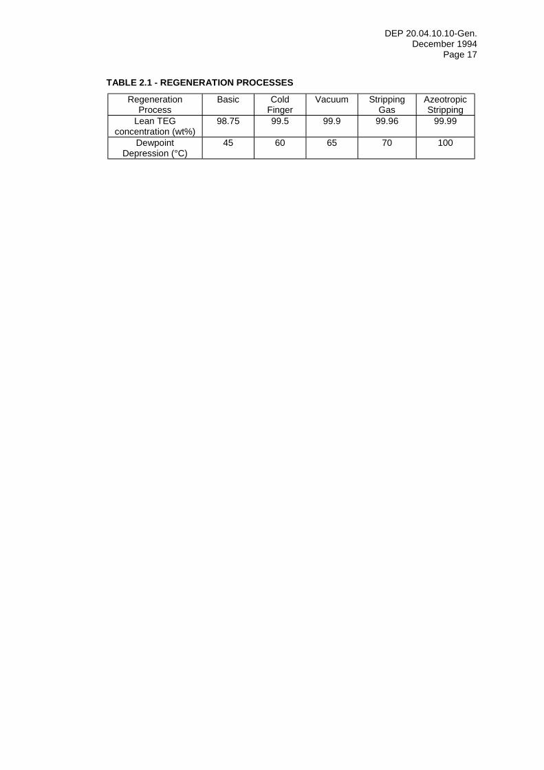
A range of lean TEG concentrations can be achieved with the basic regeneration flow schemes and various enhancements summarised in Table 2.1 and further described in (2.2) through (2.5). It should be noted that the corresponding dewpoint depressions are approximate and achievable figures are affected by actual process conditions.
DEP 20.04.10.10-Gen. December 1994
Page 17
TABLE 2.1 - REGENERATION PROCESSES
Regeneration Process
Basic Cold Finger
Vacuum Stripping Gas
Azeotropic Stripping
Lean TEG concentration (wt%)
98.75 99.5 99.9 99.96 99.99
Dewpoint Depression (°C)
45 60 65 70 100
DEP 20.04.10.10-Gen. December 1994
Page 18
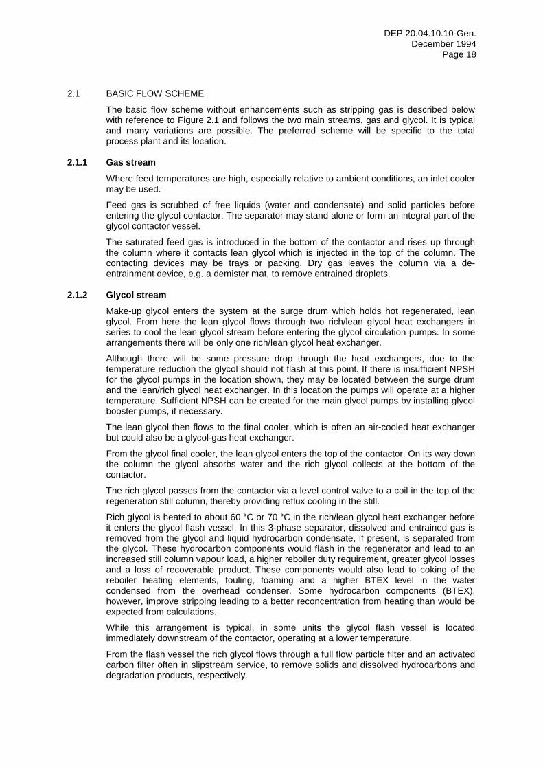
2.1 BASIC FLOW SCHEME
The basic flow scheme without enhancements such as stripping gas is described below with reference to Figure 2.1 and follows the two main streams, gas and glycol. It is typical and many variations are possible. The preferred scheme will be specific to the total process plant and its location.
2.1.1 Gas stream Where feed temperatures are high, especially relative to ambient conditions, an inlet cooler may be used.
Feed gas is scrubbed of free liquids (water and condensate) and solid particles before entering the glycol contactor. The separator may stand alone or form an integral part of the glycol contactor vessel.
The saturated feed gas is introduced in the bottom of the contactor and rises up through the column where it contacts lean glycol which is injected in the top of the column. The contacting devices may be trays or packing. Dry gas leaves the column via a de-entrainment device, e.g. a demister mat, to remove entrained droplets.
2.1.2 Glycol stream Make-up glycol enters the system at the surge drum which holds hot regenerated, lean glycol. From here the lean glycol flows through two rich/lean glycol heat exchangers in series to cool the lean glycol stream before entering the glycol circulation pumps. In some arrangements there will be only one rich/lean glycol heat exchanger.
Although there will be some pressure drop through the heat exchangers, due to the temperature reduction the glycol should not flash at this point. If there is insufficient NPSH for the glycol pumps in the location shown, they may be located between the surge drum and the lean/rich glycol heat exchanger. In this location the pumps will operate at a higher temperature. Sufficient NPSH can be created for the main glycol pumps by installing glycol booster pumps, if necessary.
The lean glycol then flows to the final cooler, which is often an air-cooled heat exchanger but could also be a glycol-gas heat exchanger.
From the glycol final cooler, the lean glycol enters the top of the contactor. On its way down the column the glycol absorbs water and the rich glycol collects at the bottom of the contactor.
The rich glycol passes from the contactor via a level control valve to a coil in the top of the regeneration still column, thereby providing reflux cooling in the still.
Rich glycol is heated to about 60 °C or 70 °C in the rich/lean glycol heat exchanger before it enters the glycol flash vessel. In this 3-phase separator, dissolved and entrained gas is removed from the glycol and liquid hydrocarbon condensate, if present, is separated from the glycol. These hydrocarbon components would flash in the regenerator and lead to an increased still column vapour load, a higher reboiler duty requirement, greater glycol losses and a loss of recoverable product. These components would also lead to coking of the reboiler heating elements, fouling, foaming and a higher BTEX level in the water condensed from the overhead condenser. Some hydrocarbon components (BTEX), however, improve stripping leading to a better reconcentration from heating than would be expected from calculations.
While this arrangement is typical, in some units the glycol flash vessel is located immediately downstream of the contactor, operating at a lower temperature.
From the flash vessel the rich glycol flows through a full flow particle filter and an activated carbon filter often in slipstream service, to remove solids and dissolved hydrocarbons and degradation products, respectively.
DEP 20.04.10.10-Gen. December 1994
Page 19
The rich glycol is further heated in a second rich/lean glycol heat exchanger and then flows to the regenerator still column between two sections of packing. This is a typical arrangement, in some systems the glycol flows directly to the regenerator without passing through a second glycol/glycol heat exchanger.
Heat is provided at the bottom of the regenerator evaporating water from the glycol. The reboiler may be directly fired or indirectly heated by electricity, hot oil or steam. Typical operating temperatures are up to 204 °C. Water and volatile species present are evaporated from the rich glycol, the reflux is provided to reduce glycol losses. Because of the wide difference in volatility only a small reflux is needed to effect water/glycol separation.
DEP 20.04.10.10-Gen. December 1994
Page 20
2.2 COLDFINGER
Gas Conditioners International Co., Irvine, California is the exclusive licenser of the "Coldfinger" patented process (No. 4332643) which has been used in at a number of locations, mostly in the USA, to give enhanced glycol regeneration. It consists of a heat exchanger tube bundle with a liquid collection trough on its underside which is inserted into the vapour space of the surge drum. The heat exchanger tubes are fed with either rich glycol before flowing to the still column reflux, or with cooling water, which gives a lower temperature. This "cold finger" leads to condensation of some vapour which is richer in water than the regenerated TEG in the liquid space of the surge drum. The condensed vapours collected in the trough are continuously recycled back to the still column feed which leads to leaner TEG in the surge drum. Further details on the Coldfinger process design are described in (3.12).
DEP 20.04.10.10-Gen. December 1994
Page 21
2.3 VACUUM
The vacuum process utilises a low partial pressure over the glycol solution to achieve a higher glycol concentration. This is achieved by drawing a vacuum on the stripping column. These units are not common due to their high operating costs, control complexity and problems with glycol degradation due to air leaks. This process is not considered further in this DEP.
DEP 20.04.10.10-Gen. December 1994
Page 22
2.4 GAS STRIPPING
Injection of stripping gas via a sparge pipe in the surge drum or via a packed stripping column with a counter-current glycol flow increases glycol concentration. The latter alternative is preferred since it allows either a glycol concentration of 99.96 percent instead of 99.9 percent to be achieved or alternatively a reduction in the stripping gas rate. Stripping gas may be drawn from the fuel gas system. The details of gas stripping process design are described in (3.13). The use of gas stripping, however, is not recommended due to the increase of hydrocarbon emissions, see EP 94-0930.
DEP 20.04.10.10-Gen. December 1994
Page 23
2.5 AZEOTROPIC STRIPPING
OPC Engineering, Houston, is the exclusive licenser of the "DRIZO" patented process to give enhanced regeneration of glycol, see Figure 2.2. It utilises a circulating solvent, such as heptane or octane, to remove water by azeotropic stripping. The regenerator vapours are condensed in a 3-phase separator and condensed solvent is returned to the regenerator via a pump and solvent heaters. Some solvent is lost in the remaining vapour stream to vent. Depending on the composition of the gas being dried, sufficient heavy ends can be absorbed by the glycol in the contactor to more than compensate for these losses. Thus, an initial charge may only be needed for start-up and excess hydrocarbon liquid can be recovered as a product. Further details of the DRIZO process are given in (3.14).
DEP 20.04.10.10-Gen. December 1994
Page 24
2.6 ACID GAS SOLUBILITIES AND STRIPPING
CO2 and/or H2S, when present in significant quantities, have the following effects:
- they increase the saturation water content of natural gas, see Figure 2.5; - they readily dissolve in glycol, reducing its pH and promoting corrosion. See Figures 2.6
and 2.7 for H2S and CO2 solubilities in TEG, respectively; - CO2 and H2S react with MEA, an acid neutraliser. See (5.1.5.3).
For high CO2 and/or H2S contents, it may be advantageous to employ a stripper upstream of the glycol flash vessel, see Figure 2.8. This approach can reduce corrosion, the flare SO2 level and the size of the glycol reboiler and still. The Principal shall be consulted for detailed advice on stripping of acid gases.
DEP 20.04.10.10-Gen. December 1994
Page 25
2.7 DEHYDRATION OF CO2
The dehydration of CO2 such as for enhanced oil recovery is fundamentally the same as dehydration of sweet natural gas. The equilibrium of H2O-TEG-CO2 is similar to that of H2O-TEG-sweet natural gas at high glycol concentrations. Thus glycol contactors may be designed using the conventional sweet gas method. There are, however, important differences requiring modifications to the design method.
2.7.1 Saturation water content of CO2
Figure 2.9 shows the saturation water content of CO2 and, for comparison, sweet natural gas at various pressures and temperatures. In the low pressure range, the behaviour of CO2 is similar to natural gas. As the pressure approaches the critical pressure of CO2, a radical deviation from natural gas behaviour occurs. Near and immediately above the critical pressure, CO2 exhibits a great increase in solubility for many compounds, including water. At increasing pressures above critical pressure, the solubility levels out.
The specification of the treated gas water content will depend on knowing the water content at the system minimum temperature and the "worst case" pressure. Where the water content of CO2 is known at the inlet condition, the water to be removed can be determined. In some cases it may be possible to dehydrate CO2 by simply cooling at the pressure at which the minimum water content occurs.
2.7.2 Mutual solubilities Data on the solubility of CO2 in TEG and TEG in CO2 are given in Figures 2.7 and 2.10, respectively. The regeneration system design shall consider the water load and CO2 solubility in glycol. Glycol make-up rates shall be based on the glycol vapour loss in the treated gas, solubility in condensate and vaporisation in the regeneration still column. NOTE: Published data for water content in CO2 and glycol/CO2 mutual solubilities are based on pure CO2. A
small quantity of a diluent, such as methane, could significantly influence these data and the data should be verified by calculation using a computer simulation program, e.g. Simulation Science's PRO/II(S).
2.7.3 Process design consideration From the pressure-volume curves for CO2 given in Figure 2.11, it is evident that the selection of dehydration operating conditions determines whether the CO2 will be vapour, liquid, supercritical or two-phase. The latter shall be avoided.
CO2 is often available at low, subcritical pressure and needs to be compressed for injection or pipeline delivery. The advantage of dehydrating at below the critical pressure, of 5 MPa, is reduced glycol losses in the gas phase. Guidelines for the selection of the operating pressure are broadly as follows:
DEP 20.04.10.10-Gen. December 1994
Page 26
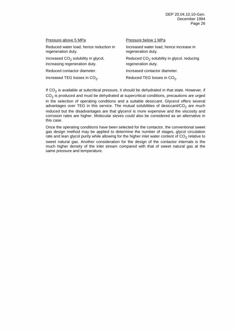
Pressure above 5 MPa Pressure below 1 MPa
Reduced water load, hence reduction in regeneration duty.
Increased water load, hence increase in regeneration duty.
Increased CO2 solubility in glycol, increasing regeneration duty.
Reduced CO2 solubility in glycol, reducing regeneration duty.
Reduced contactor diameter. Increased contactor diameter.
Increased TEG losses in CO2. Reduced TEG losses in CO2.
If CO2 is available at subcritical pressure, it should be dehydrated in that state. However, if CO2 is produced and must be dehydrated at supercritical conditions, precautions are urged in the selection of operating conditions and a suitable desiccant. Glycerol offers several advantages over TEG in this service. The mutual solubilities of desiccant/CO2 are much reduced but the disadvantages are that glycerol is more expensive and the viscosity and corrosion rates are higher. Molecular sieves could also be considered as an alternative in this case.
Once the operating conditions have been selected for the contactor, the conventional sweet gas design method may be applied to determine the number of stages, glycol circulation rate and lean glycol purity while allowing for the higher inlet water content of CO2 relative to sweet natural gas. Another consideration for the design of the contactor internals is the much higher density of the inlet stream compared with that of sweet natural gas at the same pressure and temperature.
DEP 20.04.10.10-Gen. December 1994
Page 27
2.8 MERCURY IN THE FEED GAS
The presence of mercury in the feed gas will lead to contamination of the entire glycol system. Used glycol and filters shall be stored in a safe, confined area and disposed of in an environmentally acceptable manner. There are also consequences for the design of the filters themselves, see (3.9).
The overhead condenser and separator reduces the mercury content of the residual vapour but may not eliminate the need for an activated carbon filter impregnated with sulphur for this stream, see (3.9.2).
There is also the possibility of mercury induced stress cracking in small bore pipelines, hence precautions should be taken in the material selection, especially for instrument connections.
DEP 20.04.10.10-Gen. December 1994
Page 28
2.9 PROCESS VARIABLES
The overall design of a glycol system requires optimisation of many components that interact with each other. The design basis should also allow for anticipated variations in operating conditions over the life of the plant.
Glycol dehydration system design is governed by the total glycol circulation capacity and the process variables discussed below. In general, the total circulation rate is determined by the amount of water removal required.
The water dewpoint depression, expressed as inlet dewpoint minus outlet dewpoint, is dependent on glycol circulation rate in litres per kg of water removed, lean the glycol concentration, the number of trays or depth of packing in the contactor and the contact temperature. The required dewpoint may be obtained with different combinations of these variables. Figure 2.3, which is typical, shows that the dewpoint depression is increased with leaner glycol, more trays or packing and higher glycol circulation rates. The curves in Figure 2.3 are for 38 °C contact temperatures only and should not be used for other temperatures.
2.9.1 Lean glycol concentration The lean glycol concentration has the greatest effect on the dewpoint depression. For standard dehydration systems, the factors affecting concentration are the reboiler operating temperature and the quantity of stripping gas used. Increasing the lean glycol concentration alleviates the equilibrium limitation.
2.9.2 Inlet gas temperature Inlet gas temperature is a significant variable. Higher gas temperatures require more glycol circulation, since: - there is an exponential increase in the water vapour content of the saturated gas, see
Figure 2.4; - the higher inlet dewpoint requires a higher dewpoint depression for a given outlet
dewpoint; - a higher unit circulation rate (UCR) is required due to an increase in the equilibrium
value of water for a given lean glycol concentration.
Higher temperatures also reduce the gas density leading to a higher volumetric gas flow and load factor.
Although it is desirable to have low inlet gas temperatures, 15 °C is considered to be the minimum operating temperature for bubble cap trays due to the high viscosity of glycol at lower temperatures. This temperature limit is lower for structured packing since the agitation and foaming caused by bubble caps is not present. However, caution is still advised since, depending on the pressure, hydrates may form if the temperature of the water saturated gas is less than about 20 °C. As a rule of thumb it is desirable to have the inlet temperature at least 5 °C above the hydrate formation temperature.
Gas cooling upstream of the inlet scrubber is generally recommended, especially for temperatures above 50 °C, since it is usually more economic than providing increased glycol circulation and regeneration capacity. Reducing the glycol circulation rate is also preferred to reduce losses and the aromatic component discharges. Glycol needs to be slightly warmer than the gas to avoid hydrocarbon condensation. About 60 °C is the upper practical temperature limit for glycol dehydration because of high glycol vaporisation losses.
2.9.3 Pressure Operation is theoretically possible up to pressures of 15 to 20 MPa. However, in practice operations at pressures above 13.5 MPa, i.e. outside the 900 # ANSI pressure rating, would be unlikely. The HETP increases with pressure and glycol vapour loss may become excessive at gas densities greater than about 100 kg/m3. Figure 2.12 shows estimated
DEP 20.04.10.10-Gen. December 1994
Page 29
TEG solubility in gas as a function of gas density and temperature. This is a calculated function, not based on experimental work, and should therefore be used for guidance only. The Principal should be consulted where systems may operate above these conditions.
At pressures below about 3.5 MPa, the gas contains significantly more water vapour, see Figure 2.4. The heat of absorption of the water vapour increases the contact temperature.
2.9.4 Circulation rate Total glycol circulation rate is a function of the total amount of water to be removed from the gas and the UCR. As indicated in (2.9.2), a higher inlet gas temperature increases the water vapour content of the saturated gas, the dewpoint depression required, and the UCR, all of which compound total circulation requirement. The design total circulation rate should be selected for a gas inlet temperature that will not be exceeded for more than 5 percent of the time under any ambient or process conditions.
Increasing the circulation rate will increase the dewpoint depression by providing a higher mean difference between the operating and equilibrium lines. However, for UCRs above 40 litres per kg, the improvement is usually small. Increasing the number of trays (or packing height) or the glycol concentration are generally more effective means to increase the dewpoint depression, especially when the percentage of the inlet water to be removed is high. A lower circulation rate will also reduce the sensible heat requirement of the system. A minimum design UCR of 18 litres per kg is recommended. Typically UCR varies between 25 and 40 litres of glycol per kg of water removed.
2.9.5 Methods of increasing dewpoint depression For a given number of trays, e.g. on an existing unit, a higher dewpoint depression can be achieved by increasing the circulation rate and/or increasing the lean glycol concentration. Increased circulation rates require additional sensible heat in the regenerator (the latent heat remains unchanged), and glycol concentrations above 98.75 percent require stripping gas or another enhanced regeneration method. The percentage of operating time which requires a high rate or a high concentration should be considered. The choice between the alternatives for increasing the dewpoint depression depends on economic and/or environmental aspects.
DEP 20.04.10.10-Gen. December 1994
Page 30
3 DESIGN GUIDELINES FOR GAS DEHYDRATION SYSTEMS This section recommends the minimum requirements for the design, material selection and fabrication of glycol-type gas dehydration systems. The components of a basic system without gas stripping are described in (3.1) through (3.11). Supplementary design details for enhanced regeneration methods, namely: Coldfinger, gas stripping and azeotropic distillation (Drizo) are given in (3.12), (3.13) and (3.14), respectively. Electrical and mechanical requirements are specified in (3.15) and (3.16), respectively.
Safety and environmental concerns have been considered in these design guidelines. The general concerns relate to: I) Safety:
- the regenerator heat source; - the ignition hazard from fired heaters; - high gas inlet pressure;
II) Environmental: - flash and spent stripping gas disposal; - the absorption of BTEX and H2S components in the glycol and subsequent release in
the glycol flash vessel and more especially in the regenerator still; - the disposal of spent glycol filter elements and used glycol; - the disposal of contaminants, e.g. mercury; - toxicity and flammability properties of glycols are given in Appendix 1.
If emissions cannot be prevented at source, end-of-pipe technology should be applied, see EP 94-0930. This leads to an increase in plant complexity and may even influence the choice of dehydration process.
Glycol dehydration systems may be designed either by the Principal, the Principal's main design contractor or the Manufacturer. In each case, clear functional specifications which reflect the guidelines in this DEP should be written. This is particularly important with respect to: - safety, e.g. lay-out constraints and separation of equipment; - environmental aspects, e.g. disposal of waste streams, utilisation of waste heat; - overall control/operability of the system.
The design should encompass all the operating conditions which are anticipated. A procedure is given in EP 92-1290 for determining the number of contactor transfer units (NTU), the required glycol circulation rate and the minimum required lean glycol concentration as a function of the operating conditions. This procedure is suitable for most applications and can also be used to check existing designs. It is recommended to simulate the entire glycol system with a flowsheet computer program such as PRO/II with SMIRK or SRKM since this will give: - a full heat and material balance; - a detailed composition of the rich glycol, in particular absorption of CO2, H2S and
aromatics; - a full simulation of the glycol regenerator, particularly with regard to gas stripping and
refluxing of overheads.
Details of sizes and rates should be provided in the form of a Process Flow Scheme (PFS) and a Process Engineering Flow Scheme (PEFS).
The equipment described in this section shall be equipped with piping, instruments, valve actuators, level shutdown devices and other accessories herein and shown on the PEFS to make a complete and functional system. It shall be understood that sample connections, vents, low point drains and minor material items required to make the system functional are part of the assembly.

DEP 20.04.10.10-Gen. December 1994
Page 31
3.1 INLET GAS COOLER
Whenever possible the feed gas should be cooled by air or water ahead of the inlet separator, since this is generally a cheaper form of dehydration. The inlet cooler should operate above the hydrate formation temperature. The design of the inlet gas cooler is not within the scope of this DEP.
DEP 20.04.10.10-Gen. December 1994
Page 32
3.2 INLET GAS SEPARATOR
An inlet gas separator or scrubber with a minimum liquid removal efficiency of 98 percent shall be provided upstream of the dehydration unit, even if it is near a production separator. The necessity for removing entrainment from the gas stream before the contactor cannot be over-emphasised. This applies to the presence of liquid water, liquid hydrocarbons and suspended particles. Any free water that enters the contactor increases the reboiler duty, and may "salt-up" the regenerator heating elements. The presence of any hydrocarbon liquid entering the contactor will cause the mixture to foam, resulting in loss of dehydration and glycol. If the hydrocarbons get into the regenerator, it will also foul the tubes, resulting in higher tube wall temperatures and degradation of the glycol. Heat tracing may eliminate condensing liquids between the separator and the contractor. Suspended solid particles such as dirt, scale, iron oxide and iron pyrite, will also contaminate glycol solutions.
The separator can either be a separate vessel or it can be arranged inside the contactor column below the contacting section. The combination of the contactor and separator in one column offers savings in total weight, space and costs. Liquids that might otherwise condense in the piping between the separator and contactor are also avoided.
Separate vessels should therefore be used only when other factors apply, such as a height limitation or a special requirement to filter solid particles. In either case DEP 31.22.05.11-Gen. should be used for the design of the separator.
The separator may either be of the demister type or a high efficiency type (SMS). In the latter case the required diameter for separation will be considerably smaller than that required for contacting. For an integral design, swaging the column and using high efficiency internals may be considered if it is economic. Note that with a swirltube design the diameter required for contacting matches that required for separation.
DEP 20.04.10.10-Gen. December 1994
Page 33
3.3 CONTACTOR
Various configurations for the contactor are possible; the main variables being the choice of contacting internals, and whether or not the inlet gas separator is arranged in the column. Figures 3.1 through 3.6 show the different configurations.
For contactors with an external separator, the LZA(HH) for the glycol should be determined according to Appendix V of DEP 31.22.05.11-Gen. There should be 3 minutes liquid residence time between the LA(L) and LA(H). There should be sufficient volume above LA(HH) to take into account drainage of glycol from the contacting section and, if present, the liquid distributor after a shutdown. For structural packing a liquid hold-up of 5 percent of the packaged volume should be assumed.
The contactor shell shall meet the requirements of either DEP 31.22.10.32-Gen. or DEP 31.22.20.31-Gen. depending on whether the vessel is being designed to BS 5500 or ASME VIII. It shall be carbon steel with a minimum corrosion allowance of 3 mm. A 3 mm thick AISI 316L stainless steel cladding shall be applied below the bottom tray when bubble caps are used or below the chimney tray when structured packing or swirltubes are used. All internals shall be AISI 316L stainless steel. Manufacturers shall be required to provide fully dimensioned and detailed drawings of the internals, including layout and location of gas risers, liquid inlet and, where applicable, drip pipes. Internal gaskets should be of Viton 'B' material or equivalent. A skim line is required from the bottom section of the contactor to prevent accumulation of condensate. This should be located such that condensate can be skimmed with glycol at the normal operating level.
3.3.1 Chimney tray A chimney tray is required immediately below the contacting section for all configurations except for bubble cap trays with an external separator (Figure 3.1). The chimney may collect the wet glycol and, for columns with an integral separator, it provides a liquid volume for level control. For columns with either structured packing or swirltube trays, this tray also acts as a gas distributor.
The design of the chimney tray is shown in Figure 3.7. To prevent liquid splashes entering the risers, it is essential that the riser cap walls extend to the elevation of the riser top. This is critical when there is more than one riser. The chimney tray should be liquid-tight and preferably seal-welded. A leak test shall be performed when internal gaskets are used to seal the chimney tray. Chimney trays in columns without an inlet separator shall have their liquid downcomer pipes sufficiently submerged into the rich glycol in the bottom compartment of the contactor to ensure reliable sealing.
The number and diameter of risers (dr) in the chimney tray shall be selected to meet the following requirements: - the combined riser area is 15 to 20 percent of column cross-sectional area; - the riser pressure drop (3.3.10) should be a minimum of 0.05 kPa to create an even
distribution of gas flow; - the diameter of each riser is 0.2 to 0.3 m (except for swirltube trayed contactors); - for swirltube trayed contactors, the number of risers equals the number of contactor
swirltubes.
The height of the chimney tray risers (hc) is governed mainly by whether or not there is an integral separator in the column. If there is an integral separator, a liquid residence time will be required for control. The elevation of LZA (HH) should then be determined using the same method and allowances described in (3.3), first paragraphs.
If there is no integral separator, the height of the chimney risers should be determined from the equation:
hc = 0.67 Nr(ql/X)0.667 + 0.5 dr (m), where
Nr = number of rows of risers perpendicular to the liquid flow over the tray to the
DEP 20.04.10.10-Gen. December 1994
Page 34
drain pipe ql = liquid flowrate (m3/s) dr = riser diameter (m) X = smallest free passage for liquid in any row (m) hc is rounded up to a multiple of 0.05 m.
The drain pipe should be sized as a liquid outlet nozzle (3.3.8).
3.3.2 Contacting internals The options for the contacting internals include bubble cap trays, valve trays, random packing, structured packing and swirltube trays. The use of structured packing is recommended in view of its high specific gas capacity and low glycol entrainment characteristics, further reduction in column diameter can be achieved by using swirltube trays.
3.3.2.1 Bubble cap trays
Prior to the late eighties, most glycol contactors used bubble cap trays. They have proved effective and reliable and have good gas and liquid turndown ratios; the latter being limited primarily by the bypassing of gas. There is industry experience with columns up to 4.2 m in diameter with bubble cap trays.
The gas turndown for bubble caps is superior to that for valve trays, and turndown to 10 percent of design flow is guaranteed by tray manufacturers. Turndown requirements should be stated in the specification. For gas flow rates below about 40 percent of design, the tray efficiency may decrease. However, at these reduced rates the system will have ample total circulation capacity to enable increasing UCR if required. Blinding off several of the bubble caps has been proven as a cheap and effective way of overcoming dewpoint problems at high turndown ratios.
For design purposes most manufacturers use tray efficiencies in the range of 25 to 33 percent, although actual efficiency may differ.
A large variety of bubble cap tray designs are available from different tray manufacturers. The performance of the trays in glycol contactor duty is not dependent on the type of bubble cap installed. It is not necessary, therefore, for details on the layout of the bubble caps to be fully specified. The following criteria should be fulfilled to ensure an optimum performance of the trays: - the column diameter should be sufficient for the vapour flow (3.3.3); - the downward liquid velocity in the top of the downcomer and/or the downcomer pipes
should be less than 0.07 m/s under maximum flow conditions. This is to prevent choking;
- the downcomer area should be a minimum of 11 percent of the column cross-sectional area. A smaller downcomer area might lead to maldistribution of liquid, which in turn could cause a drop in efficiency;
- an outlet weir of 100 mm height should be used. Lower weir heights will result in reduced efficiency;
- back-up in the downcomer should be sufficiently low to prevent premature flooding. This is not usually a problem for a properly designed column. For new designs this should be made the responsibility of the Contractor and/or tray Supplier;
- the glycol inlet to the top tray should be carefully positioned in order to ensure good distribution.
3.3.2.2 Valve trays
Valve trays have about 10 to 15 percent greater capacity than bubble cap trays for a given contactor diameter and, at design gas flow rates, possibly a little higher efficiency. However, due to their design, valve trays are more prone to weeping, i.e. liquid seepage through the valves. This is not significant at relatively high liquid rates, but with the low liquid rates normally encountered in glycol contactors, weeping causes the column to be
DEP 20.04.10.10-Gen. December 1994
Page 35
inefficient unless the glycol rate is maintained at a high level. For this reason, valve trays are rarely used for glycol contactors and are not covered further in this DEP.
3.3.2.3 Random packing
Random (or dumped) packings, consisting of ceramic saddles or pall rings, are not as well suited to glycol contactors as structured packings or trays due to the high gas-liquid ratios. They were previously used in preference to bubble cap trays, in small diameter columns less than 450 mm diameter due to easier installation and lower cost. With the greater application of structured packing and its availability in diameters down to 100 to 200 mm, random packing is rarely used now for glycol contactor internals. No further reference is therefore made to random packing for contactors in this DEP.
3.3.2.4 Structured packing
At low liquid loads such as encountered in glycol contactors, structured packings are superior to random packing because of their higher specific area and better mass transfer efficiency.
The gas handling capacity of structured packings is about 150 to 190 percent greater than that of bubble cap trays, which allows smaller diameters and thus cheaper contactors. Safety is also enhanced due to lower hydrocarbon inventories.
A gas turndown ratio of 10 to 1 can be achieved with structured packing, and the glycol losses due to carry-over of liquid from the contactor are extremely low. The latter can be explained by the liquid film formed on packing, which is not as easily entrained as the liquid from a droplet bed on a tray. However, reduction in carry-over can lead to a more rapid accumulation of impurities in the glycol inventory and the need for a replacement or purification programme.
Structured packings can also be attractive for revamping existing columns in order to increase the gas handling capacity, to reduce the glycol carry-over from the contactor, or to improve the dewpoint suppression capability, see (4.2.1).
The recommended minimum liquid superficial velocity based on contactor cross-sectional area for structured packing is 0.5 mm/s to ensure complete wetting of the packing surface area.
Structured packings and their liquid distributors are more sensitive to liquid turndown and these should be checked to ensure that unnecessarily high total circulation rates will not be required to meet either the minimum liquid loading of the packing or the minimum HOW of the distributor. Liquid distributors will typically have a turndown of about 2 to 1. It is therefore important to select a distributor that is designed for the desired glycol circulation rate. Liquid distributors can be easily replaced should plant operating conditions change during the lifetime of the facility.
In applications where inlet gas rates or temperatures are likely to be considerably below design rates over much of the facility life, the inability to reduce the glycol circulation rate can add significantly to operating costs and increase the sensible heat duty of the reboiler. The latent heat required to vaporise the absorbed water will not increase since the design of the contactor takes into account the higher glycol unit circulation rate. Similarly, the potential BTEX emissions from the regeneration still column and glycol flash vessel should not be greatly affected.
The minimum thickness of the structured packing sheet material is 0.15 mm. AISI 316L stainless steel is recommended because of possible chloride attack due to entrainment of saline water.
The packing should be specified for the column internal diameter. Sealing at the vessel wall is ensured by wall scrapers as part of the packing supply. Packing, packing supports, hold-down grids and liquid distributor should be supplied by a single manufacturer.
DEP 20.04.10.10-Gen. December 1994
Page 36
3.3.2.5 Swirltube trays
Contacting swirltube trays are a recent development that have been successfully field tested. Vanes are used to impart a rotation to the gas which forces the liquid droplets to the wall of the tube where they are collected. The Principal shall be consulted regarding their potential application.
The gas handling capacity of swirltube trays is of the order of four times that of bubble cap trays. At gas flows as low as about 30 percent of design, contacting occurs with co-current upward flow of glycol and gas in the swirltubes. A gas turndown to 20 percent is achievable in combination with a higher unit circulation rate. At the lowest gas flows contacting occurs with counter-current (downward) glycol flow. At maximum capacity glycol losses are extremely low, similar to structured packing.
Swirltube trays are more expensive than structured packing for the same capacity. However, for typical operating conditions and capacities of about 5 million m3(st)/d or more, this is more than offset by substantial cost savings for the column shell. Savings will be even greater for offshore applications when reduced weight and space are considered. Furthermore, lower hydrocarbon inventories will enhance safety.
3.3.3 Column diameter The column diameter is governed by the gas load in the contacting section and is not affected by the glycol circulation rate.
The design shall be based on the operation mode under the severest conditions with the highest value of the volumetric load factor Q*, defined by:
m3/s
where ρl is the density of the rich glycol leaving the contactor.
Having identified the most severe loading from the highest value of Q*, it is then necessary to add a margin to give the value on which the design shall be based. This value, Q*max, should include margins for inaccuracies in basic data, for operational flexibility and for surging.
The following design margins are recommended for new designs and revamps of existing bubble cap tray contactors.
Design margin New design 20 percent Revamp 15 percent The column inside diameter may be calculated from:
m
in which λmax is the maximum allowable gas load factor, corresponding to the onset of entrainment.
A λmax of 0.055 m/s should be used for bubble cap trays at 0.6 m spacing. For smaller tray spacings the capacity decreases as:
m/s
With greater tray spacings only a marginal improvement is achieved.
DEP 20.04.10.10-Gen. December 1994
Page 37
λmax is higher for structured packings and, depending on the type selected, the column diameter required is a factor of 1.4 to 1.25 smaller than that required for bubble cap trays. Data on load factors for structured packings and swirl tube trays are given in EP 92-1290.
3.3.4 Contacting section The relationship between a bubble cap tray, a swirltube tray or a unit height of structured packing and the NTU is given in EP 92-1290.
3.3.4.1 Bubble cap and swirltube trays
The number of actual trays required, N, is determined by the NTU required for the process and the NTU per tray, rounded up to the next whole number. The height of the contacting section follows from N and the tray spacing. For bubble cap trays a spacing of 0.6 m is recommended. Above the top tray, double TS to the demister should be applied to minimise the glycol losses from the contactor.
Trays shall be designed in accordance with DEP 31.20.20.31-Gen. They shall be installed level, sealed properly and be removable for cleaning. The Supplier shall describe any modifications necessary to allow the contactor to handle 20 percent of the specified gas rate.
3.3.4.2 Structured packing
The packing height is determined by the NTU required for the process duty and the HTU. Structured packing consists of prefabricated elements with a given height, typically 190 to 250 mm. The calculated packing height should be rounded up to a multiple of this height. In special cases, e.g. revamps, a packing layer with half the height can be specified as the top layer.
3.3.5 Liquid distributor A liquid distributor is required when packing or swirltube trays are used. It consists of a number of liquid drip pipes and vapour risers evenly distributed over the column cross-sectional area. An effective design of liquid distributor is essential for the performance of packing or swirltube trays.
Despite glycol filtering, see (3.9.1), the liquid distributor should as a precaution be capable of handling fouled liquid. Gravity-flow distributors with holes in a flat bottom plate shall not be used, since they tend to plug.
Liquid distributor drip pipes shall be installed after the erection of the column. The drip pipes shall be level to within 0.3 percent of the column diameter or 6 mm across the column diameter, whichever is the smaller. It is essential that static and operational thermal loads do not compromise the strict levelness specification. Distributor segments and supports should be designed to resist sagging and shall not be unduly affected by expansion or contraction.
Liquid distributors may be attached to the support of the top tray or, via spacers, to the support ring of the demister in the top of the contactor. Liquid distributors resting on the packing without attachment to the vessel are not acceptable. Troughs, gutters and pans must be fixed to the column wall and not simply rest on supports or the packing.
3.3.5.1 Layout
The layout of the liquid distributor should be as simple as possible. Typical layouts of a Shell proprietary distributor for structured packing are shown in Figure 3.8.
For column diameters less than 1.5 m (Figure 3.8A), the gas risers are tubular and evenly spaced across the column. The example shows 4 connected panels with 1 row of risers and 2 rows of drip-pipes per panel. In this pan-type distributor, the liquid is fed onto the distributor tray via a single pipe at the centre of the distributor. This pipe should terminate 50 mm above the tray level and its maximum allowable liquid velocity is 1 m/s.
DEP 20.04.10.10-Gen. December 1994
Page 38
To ensure satisfactory initial liquid distribution on top of the packing, the recommended number of drip-pipes per square metre of column cross-section is 60 and 80 for structured packing with specific areas of 200 to 250 and 300 to 350 m2/m3, respectively. It is important that the area near the column wall is properly irrigated. To ensure this, the distance between the drip pipes near to the column wall shall be about half the distance between the drip pipes in the rest of the column.
Although liquid distribution is less critical for swirltube trays, the lean TEG has to be pre-distributed to avoid strong hydrodynamic gradients on the top contacting tray and liquid maldistribution. The liquid distributor may be integrated with the de-entrainment separation swirl deck, making use of the space available due to the standard pitch of separation tubes being less than the pitch of contacting tubes.
The cross-sectional area of the gas risers shall be at least 25 percent of that of the column.
The distributor should not overflow at less than 110 percent of the contactor flooding flowrate.
In a trough-and-gutter type of distributor, the floor of the main trough is shown lower than that of the side gutters. The liquid level will be common, and the drip-pipe holes shall have the same elevation to achieve equal flow through the drip-pipes.
3.3.5.2 Drip pipes
Drip pipes should be designed as follows, see also Figure 3.10: - they shall extend above the bottom plate to form an accumulation volume for dirt; - the drip pipes may be equipped with holes or slits to ensure sufficient liquid height or
crest-over-weir (HOW). Drip pipes with holes are not as sensitive to being out of level and should be used for new designs in preference to pipes with slits. In the case of slits, a rectangular slit is preferred to a V-notch because the latter may have a stronger tendency to retain solids in the bottom point. The Principal shall be consulted for the relationship between HOW, liquid flowrate and driphole or slit size;
- the drip pipes typically have an inner diameter of 10 mm but this might be modified by a maximum allowable liquid velocity of 0.5 m/s;
- the drip pipes extend below the bottom plate of the distributor to prevent liquid entrainment by the gas, and the distance from top of the packing to bottom of drip pipe is typically 10 - 50 mm;
- fixed welded rather than adjustable drip pipes are recommended for ease of installation. Levelling may be by an adjustable distributor.
3.3.6 Liquid de-entrainment For structured packing, a demister mat shall extend over the whole contactor cross section, see also Figures 3.3 and 3.4. For bubble cap trays, a demister mat having a diameter of about 80 percent of the contactor is sufficient. A full diameter demister mat is recommended for improved efficiency, see also Figures 3.1 and 3.2. Some structured packings have a maximum allowable load factor greater than that of a demister mat as defined in DEP 31.22.05.11-Gen., but for contactor service this is still acceptable.
For swirltube contacting trays, a separation swirl deck tray shall be used as the de-entrainment device, see also Figures 3.5 and 3.6. The Principal shall be consulted for detailed design of the separation swirl deck.
Filter separators have also been used to recover glycol from the outlet gas stream, but they should not be necessary for new contactor designs using structured packing or swirltubes.
DEP 31.22.05.11-Gen. with the same volumetric load factor used for the contacting section (3.3.3), shall be used for the selection or checking of de-entrainment devices in contactors containing bubble caps.
DEP 20.04.10.10-Gen. December 1994
Page 39
3.3.7 Top manhole or flange With the exception of bubble cap trayed contactors, the free space below the de-entrainment device is dictated by accessibility. A full diameter top flange is recommended in preference to a manhole for contactors up to 1.5 m since: - internals are easier to install and maintain; - with a manhole, space will be inadequate or at least make internal assembly difficult; - the cost of the vessel will not be significantly different; - in the case of swirltube contactor trays, integral instead of panel assembly will be
possible, allowing a greater net free area and column load factor and a reduced contactor diameter.
A full diameter top flange will require sufficient hoisting height above the contactor and access for a crane or hoist. The pipework shall also be designed for easy dismantling. The internal free space may, however, be reduced from the 0.6 m required for a typical manhole to about 0.3 m.
3.3.8 Nozzles and gas inlet device Inlet and outlet nozzles as well as the Schoepentoeter gas inlet device shall be designed in accordance with DEP 31.22.05.11-Gen.
3.3.9 Total contactor height The height of the contactor is based on the heights of the internals indicated in Figures 3.1 to 3.6. For a packed column, the hold-down grids should be integrated with the distributor space and the support grid should be installed in the free space below the packing.
3.3.10 Pressure drop The pressure drop over a glycol contactor is the sum of pressure drops over the internals:
- inlet and outlet nozzles; - demister mats; - separation swirl decks; - chimney tray; - contacting section; - liquid distributor.
Pressure drop equations for the first three items are given in DEP 31.22.05.11-Gen.; however, for the de-entrainment swirl deck in a contactor with contacting swirltubes, a constant of 11 instead of 8.4 shall be used.
The following equations can be used for the remaining items:
Pressure drop over chimney tray:
∆P = 2ρ gvg2 x 10-3 kPa
Pressure drop over bubble cap trays:
∆P = 1 kPa/tray is typical. Accurate figures should be obtained from tray manufacturers.
Pressure drop over structured packing below 80 percent of maximum load:
kPa/m
λmax is packing-dependent, see EP 92-1290
λ = the actual gas load factor.
Pressure drop over the liquid distributor:

DEP 20.04.10.10-Gen. December 1994
Page 40
∆P 2ρgvg2 x 10-3 kPa
Actual gas velocity must be calculated through chimney tray and liquid distributor.
Structured packing, or possibly swirltube trays, should be used for new designs since they offer significant advantages in weight, space and cost of the contactor. The Principal should be consulted before application of swirltube trays.
DEP 20.04.10.10-Gen. December 1994
Page 41
3.4 GLYCOL REGENERATOR
The glycol regenerator includes a reboiler to supply heat for the glycol system operation and is sized for the total heat demand. This is governed primarily by the total glycol circulation rate and the quantity of water removed, and secondly by the efficiency of heat exchange and system losses. Heat is required for vaporising the water to regenerate the glycol, for sensible heat lost to the treated gas stream and for system heat losses. For small or swing units, reboiler heat duties are usually defined by their cold start-up requirements.
Data on typical onshore TEG regenerators are given in Table 3.1.
3.4.1 Reboiler Unless otherwise noted, each requirement in this DEP applies to equipment for both onshore and offshore service. See (3.5.3) for sizing indirectly heated reboiler heat exchange bundles. The reboiler shall have a spill-over column or a weir to prevent the heating coils from becoming exposed. The spill-over column may be packed to serve as a stripping gas contact column. A separate stripping column is, however, recommended if stripping gas is required, see (3.13.2). The reboiler bundle shall be easily removable.
The reboiler should preferably be constructed of AISI 316L clad steel. If it is carbon steel a 3 mm corrosion allowance is required, and increased inspection frequency and maintenance should be expected.
The reboiler shall be insulated for heat conservation in accordance with DEP 30.46.00.31-Gen.
3.4.1.1 Heat sources
Alternative heat sources for the glycol regenerator are: - direct gas fired; - hot oil/steam; - electricity; - turbine or engine exhaust; - furnace flue gas.
Waste heat recovery, e.g. from engine or turbine exhaust with a heating fluid system, is most common in offshore oil applications and should in all cases be considered as the preferred option for environmental reasons. Where this is not possible or reasonably practicable, electrical heating is preferred to direct fired heating for safety.
a) Direct gas fired
Direct fired heaters are most common in onshore applications due to the lower cost. The source of permanent ignition shall always be installed in a non-hazardous area and fired heaters should be located as far as practicable away from a hazardous area.
The minimum distance that a fired heater could be from process equipment is 30 m. They are not as inherently safe as waste heat recovery (except when hot oil is used) or electric heating units and need additional detection/protection measures. In common with all detection/protection systems, they require maintenance and adherence to procedures to ensure they work satisfactorily.
The air intake to the burner shall be designed to efficiently prevent wind-blown sand from entering the burner. It shall be fitted with an easily removable flame arrestor. A manway shall be provided to enable the fire tubes to be inspected. The fire tubes shall not be reduced in cross-sectional area at any elbow. Proper support of the fire tubes from the shell shall be provided, allowing for the differential expansion between the fire tubes and the shell.

DEP 20.04.10.10-Gen. December 1994
Page 42
Amended per Circular 57/03
The burner management system shall be safe and functional in accordance with DEP 31.24.00.30-Gen..
b) Hot oil/steam
A steam condensate trap and strainer with block valves and a bypass shall be provided to drain the steam condensate. The reboiler should be sized as a heat exchanger using the U-values listed in (3.5.3).
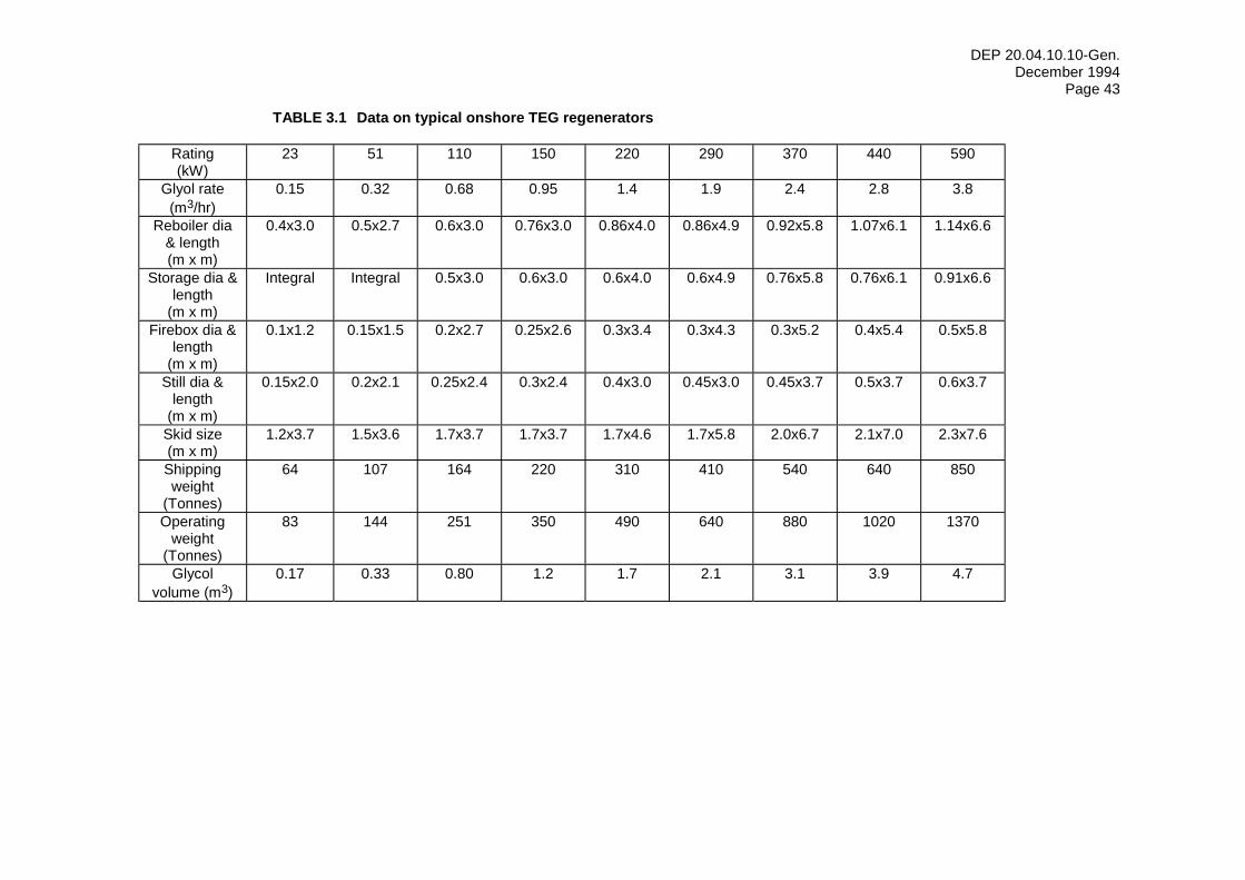
DEP 20.04.10.10-Gen. December 1994
Page 43
TABLE 3.1 Data on typical onshore TEG regenerators
Rating (kW)
23 51 110 150 220 290 370 440 590
Glyol rate (m3/hr)
0.15 0.32 0.68 0.95 1.4 1.9 2.4 2.8 3.8
Reboiler dia & length (m x m)
0.4x3.0 0.5x2.7 0.6x3.0 0.76x3.0 0.86x4.0 0.86x4.9 0.92x5.8 1.07x6.1 1.14x6.6
Storage dia & length
(m x m)
Integral Integral 0.5x3.0 0.6x3.0 0.6x4.0 0.6x4.9 0.76x5.8 0.76x6.1 0.91x6.6
Firebox dia & length
(m x m)
0.1x1.2 0.15x1.5 0.2x2.7 0.25x2.6 0.3x3.4 0.3x4.3 0.3x5.2 0.4x5.4 0.5x5.8
Still dia & length
(m x m)
0.15x2.0 0.2x2.1 0.25x2.4 0.3x2.4 0.4x3.0 0.45x3.0 0.45x3.7 0.5x3.7 0.6x3.7
Skid size (m x m)
1.2x3.7 1.5x3.6 1.7x3.7 1.7x3.7 1.7x4.6 1.7x5.8 2.0x6.7 2.1x7.0 2.3x7.6
Shipping weight
(Tonnes)
64 107 164 220 310 410 540 640 850
Operating weight
(Tonnes)
83 144 251 350 490 640 880 1020 1370
Glycol volume (m3)
0.17 0.33 0.80 1.2 1.7 2.1 3.1 3.9 4.7
DEP 20.04.10.10-Gen. December 1994
Page 44
c) Electricity
A minimum of three heating coils shall be used. Over-temperature protection of the heater elements shall be provided by means of at least two thermocouple elements clamped or welded to the heater sheath, located in an area of highest anticipated sheath temperature. Solid state proportional current control on part of the load is preferred to on-off control.
d) Turbine or engine exhaust
Where gas turbine or engine exhaust is used, coordination is required between the suppliers of the glycol system and the engine. Each supplier shall ensure that all components will operate satisfactorily together. Due consideration must be given to interactions between the engine and the glycol unit on start-up and shut-down of the engine or turbine. If more than one engine is used, each engine exhaust system shall be entirely separate from any other engine.
e) Furnace flue gas
For onshore locations, all flash gas and condensate may be incinerated in a furnace and the flue gas used as a reboiler heat source. This may be the most favourable alternative when it is necessary to dispose of all waste hydrocarbon streams.
When the feed gas contains a significant amount of mercury, a chiller is required in the flash gas line to cool it to approximately 15 °C, together with a scrubber. This will reduce the mercury content in the flue gas. The separated mercury discharged from the scrubber flows to a dedicated water handling unit, forming a mercury contaminated sludge. This sludge shall be contained and disposed of in an environmentally acceptable manner.
3.4.1.2 Temperature
It is generally environmentally favourable to maximise the lean glycol concentration by using high reboiler temperatures since this will minimise the circulation rate or the volume of stripping gas required. However, facility utility requirements should be considered. If a larger prime mover or additional generator capacity for the increased electric resistance heating is required, an economic study will determine if it is justified to increase the glycol reboiler temperature.
Improvements in glycol system design have increased the practical maximum reboiler temperature. Reboiler temperatures have been limited in the past to about 190 °C to avoid thermal degradation of the glycol, which occurs at 206 °C. Experience has shown that in a well designed system, a glycol temperature of 204 °C will not result in objectionable rates of TEG decomposition. Important factors for operating at higher temperatures include: - exclusion of oxygen from the system. This is critical at any temperature; - effective filtering; - efficient removal of the hydrocarbons in the glycol flash vessel and carbon filter; - limiting the glycol film temperature at the heating surface to about 207 °C.
The last requirement is easily met in electric and steam heated units, but may not be met in hot oil and direct fired units. If the calculated film temperatures exceed 207 °C for the latter then the maximum reboiler temperatures shall be reduced as follows:
Hot Oil 200 °C Direct Fired 193 °C Figure 3.11 shows the effect of reboiler temperature on glycol concentration. Actual concentrations may be reduced by any increase in backpressure on the still column, e.g. typically 2.5 kPa for a low pressure flare. Concentration may be increased at high altitude onshore locations and by desorption of dissolved hydrocarbons.
Stripping gas has been used to reduce the reboiler temperature required for a desired lean glycol concentration. Where a 204 °C reboiler temperature would for example require supplemental electric heating or a larger engine for exhaust heat recovery, continuous gas stripping should be considered.
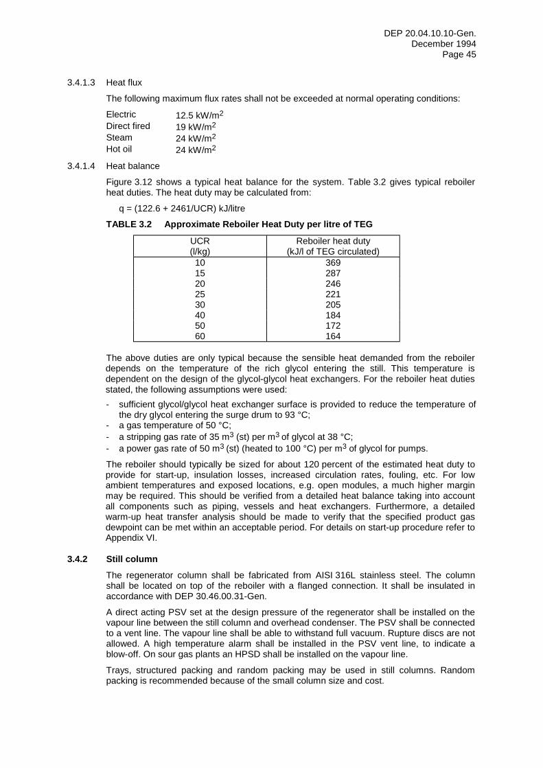
DEP 20.04.10.10-Gen. December 1994
Page 45
3.4.1.3 Heat flux
The following maximum flux rates shall not be exceeded at normal operating conditions:
Electric 12.5 kW/m2 Direct fired 19 kW/m2 Steam 24 kW/m2 Hot oil 24 kW/m2
3.4.1.4 Heat balance
Figure 3.12 shows a typical heat balance for the system. Table 3.2 gives typical reboiler heat duties. The heat duty may be calculated from:
q = (122.6 + 2461/UCR) kJ/litre
TABLE 3.2 Approximate Reboiler Heat Duty per litre of TEG
UCR (l/kg)
Reboiler heat duty (kJ/l of TEG circulated)
10 369 15 287 20 246 25 221 30 205 40 184 50 172 60 164
The above duties are only typical because the sensible heat demanded from the reboiler depends on the temperature of the rich glycol entering the still. This temperature is dependent on the design of the glycol-glycol heat exchangers. For the reboiler heat duties stated, the following assumptions were used: - sufficient glycol/glycol heat exchanger surface is provided to reduce the temperature of
the dry glycol entering the surge drum to 93 °C; - a gas temperature of 50 °C; - a stripping gas rate of 35 m3 (st) per m3 of glycol at 38 °C; - a power gas rate of 50 m3 (st) (heated to 100 °C) per m3 of glycol for pumps.
The reboiler should typically be sized for about 120 percent of the estimated heat duty to provide for start-up, insulation losses, increased circulation rates, fouling, etc. For low ambient temperatures and exposed locations, e.g. open modules, a much higher margin may be required. This should be verified from a detailed heat balance taking into account all components such as piping, vessels and heat exchangers. Furthermore, a detailed warm-up heat transfer analysis should be made to verify that the specified product gas dewpoint can be met within an acceptable period. For details on start-up procedure refer to Appendix VI.
3.4.2 Still column The regenerator column shall be fabricated from AISI 316L stainless steel. The column shall be located on top of the reboiler with a flanged connection. It shall be insulated in accordance with DEP 30.46.00.31-Gen.
A direct acting PSV set at the design pressure of the regenerator shall be installed on the vapour line between the still column and overhead condenser. The PSV shall be connected to a vent line. The vapour line shall be able to withstand full vacuum. Rupture discs are not allowed. A high temperature alarm shall be installed in the PSV vent line, to indicate a blow-off. On sour gas plants an HPSD shall be installed on the vapour line.
Trays, structured packing and random packing may be used in still columns. Random packing is recommended because of the small column size and cost.
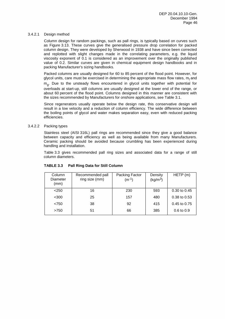
DEP 20.04.10.10-Gen. December 1994
Page 46
3.4.2.1 Design method
Column design for random packings, such as pall rings, is typically based on curves such as Figure 3.13. These curves give the generalised pressure drop correlation for packed column design. They were developed by Sherwood in 1938 and have since been corrected and replotted with slight changes made in the correlating parameters, e.g. the liquid viscosity exponent of 0.1 is considered as an improvement over the originally published value of 0.2. Similar curves are given in chemical equipment design handbooks and in packing Manufacturer's sizing handbooks.
Packed columns are usually designed for 60 to 85 percent of the flood point. However, for glycol units, care must be exercised in determining the appropriate mass flow rates, ml and mg. Due to the unsteady flows encountered in glycol units together with potential for overloads at start-up, still columns are usually designed at the lower end of the range, or about 60 percent of the flood point. Columns designed in this manner are consistent with the sizes recommended by Manufacturers for onshore applications, see Table 3.1.
Since regenerators usually operate below the design rate, this conservative design will result in a low velocity and a reduction of column efficiency. The wide difference between the boiling points of glycol and water makes separation easy, even with reduced packing efficiencies.
3.4.2.2 Packing types
Stainless steel (AISI 316L) pall rings are recommended since they give a good balance between capacity and efficiency as well as being available from many Manufacturers. Ceramic packing should be avoided because crumbling has been experienced during handling and installation.
Table 3.3 gives recommended pall ring sizes and associated data for a range of still column diameters.
TABLE 3.3 Pall Ring Data for Still Column
Column Diameter
(mm)
Recommended pall ring size (mm)
Packing Factor (m-1)
Density (kg/m3)
HETP (m)
<250 16 230 593 0.30 to 0.45
<300 25 157 480 0.38 to 0.53
<750 38 92 415 0.45 to 0.75
>750 51 66 385 0.6 to 0.9
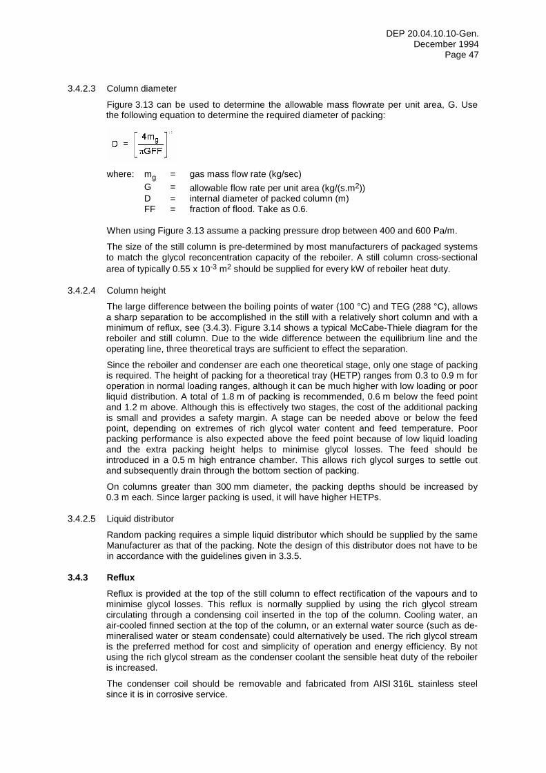
DEP 20.04.10.10-Gen. December 1994
Page 47
3.4.2.3 Column diameter
Figure 3.13 can be used to determine the allowable mass flowrate per unit area, G. Use the following equation to determine the required diameter of packing:
where: mg = gas mass flow rate (kg/sec) G = allowable flow rate per unit area (kg/(s.m2)) D = internal diameter of packed column (m) FF = fraction of flood. Take as 0.6.
When using Figure 3.13 assume a packing pressure drop between 400 and 600 Pa/m.
The size of the still column is pre-determined by most manufacturers of packaged systems to match the glycol reconcentration capacity of the reboiler. A still column cross-sectional area of typically 0.55 x 10⁻³ m2 should be supplied for every kW of reboiler heat duty.
3.4.2.4 Column height
The large difference between the boiling points of water (100 °C) and TEG (288 °C), allows a sharp separation to be accomplished in the still with a relatively short column and with a minimum of reflux, see (3.4.3). Figure 3.14 shows a typical McCabe-Thiele diagram for the reboiler and still column. Due to the wide difference between the equilibrium line and the operating line, three theoretical trays are sufficient to effect the separation.
Since the reboiler and condenser are each one theoretical stage, only one stage of packing is required. The height of packing for a theoretical tray (HETP) ranges from 0.3 to 0.9 m for operation in normal loading ranges, although it can be much higher with low loading or poor liquid distribution. A total of 1.8 m of packing is recommended, 0.6 m below the feed point and 1.2 m above. Although this is effectively two stages, the cost of the additional packing is small and provides a safety margin. A stage can be needed above or below the feed point, depending on extremes of rich glycol water content and feed temperature. Poor packing performance is also expected above the feed point because of low liquid loading and the extra packing height helps to minimise glycol losses. The feed should be introduced in a 0.5 m high entrance chamber. This allows rich glycol surges to settle out and subsequently drain through the bottom section of packing.
On columns greater than 300 mm diameter, the packing depths should be increased by 0.3 m each. Since larger packing is used, it will have higher HETPs.
3.4.2.5 Liquid distributor
Random packing requires a simple liquid distributor which should be supplied by the same Manufacturer as that of the packing. Note the design of this distributor does not have to be in accordance with the guidelines given in 3.3.5.
3.4.3 Reflux Reflux is provided at the top of the still column to effect rectification of the vapours and to minimise glycol losses. This reflux is normally supplied by using the rich glycol stream circulating through a condensing coil inserted in the top of the column. Cooling water, an air-cooled finned section at the top of the column, or an external water source (such as de-mineralised water or steam condensate) could alternatively be used. The rich glycol stream is the preferred method for cost and simplicity of operation and energy efficiency. By not using the rich glycol stream as the condenser coolant the sensible heat duty of the reboiler is increased.
The condenser coil should be removable and fabricated from AISI 316L stainless steel since it is in corrosive service.
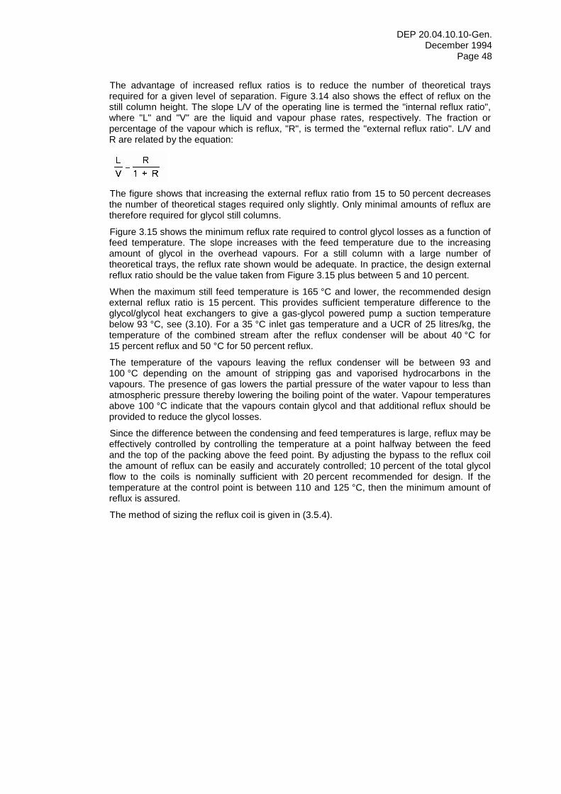
DEP 20.04.10.10-Gen. December 1994
Page 48
The advantage of increased reflux ratios is to reduce the number of theoretical trays required for a given level of separation. Figure 3.14 also shows the effect of reflux on the still column height. The slope L/V of the operating line is termed the "internal reflux ratio", where "L" and "V" are the liquid and vapour phase rates, respectively. The fraction or percentage of the vapour which is reflux, "R", is termed the "external reflux ratio". L/V and R are related by the equation:
The figure shows that increasing the external reflux ratio from 15 to 50 percent decreases the number of theoretical stages required only slightly. Only minimal amounts of reflux are therefore required for glycol still columns.
Figure 3.15 shows the minimum reflux rate required to control glycol losses as a function of feed temperature. The slope increases with the feed temperature due to the increasing amount of glycol in the overhead vapours. For a still column with a large number of theoretical trays, the reflux rate shown would be adequate. In practice, the design external reflux ratio should be the value taken from Figure 3.15 plus between 5 and 10 percent.
When the maximum still feed temperature is 165 °C and lower, the recommended design external reflux ratio is 15 percent. This provides sufficient temperature difference to the glycol/glycol heat exchangers to give a gas-glycol powered pump a suction temperature below 93 °C, see (3.10). For a 35 °C inlet gas temperature and a UCR of 25 litres/kg, the temperature of the combined stream after the reflux condenser will be about 40 °C for 15 percent reflux and 50 °C for 50 percent reflux.
The temperature of the vapours leaving the reflux condenser will be between 93 and 100 °C depending on the amount of stripping gas and vaporised hydrocarbons in the vapours. The presence of gas lowers the partial pressure of the water vapour to less than atmospheric pressure thereby lowering the boiling point of the water. Vapour temperatures above 100 °C indicate that the vapours contain glycol and that additional reflux should be provided to reduce the glycol losses.
Since the difference between the condensing and feed temperatures is large, reflux may be effectively controlled by controlling the temperature at a point halfway between the feed and the top of the packing above the feed point. By adjusting the bypass to the reflux coil the amount of reflux can be easily and accurately controlled; 10 percent of the total glycol flow to the coils is nominally sufficient with 20 percent recommended for design. If the temperature at the control point is between 110 and 125 °C, then the minimum amount of reflux is assured.
The method of sizing the reflux coil is given in (3.5.4).
DEP 20.04.10.10-Gen. December 1994
Page 49
3.5 HEAT EXCHANGERS
Heat exchangers in glycol dehydration systems have low U values because of low pressure drops and because glycol is a poor heat transfer fluid. Fouling from glycol contaminants and degradation products may also be severe. Table 3.4 gives the range of values for the exchangers discussed herein.
Exchangers shall be located and arranged to enable inspection, cleaning and removal of the tube bundles. The pressure rating of the heat exchangers shall be the same as the system design pressure. Isolation block valves, pressure and temperature gauges shall be provided in the entry and exit streams from each heat exchanger.
Shell and tube heat exchangers shall be in accordance with DEP 31.21.01.30-Gen.
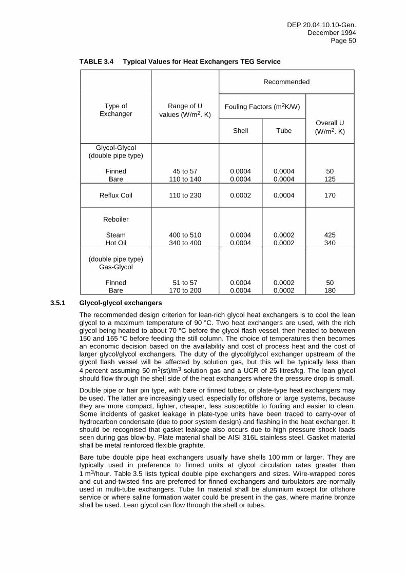
DEP 20.04.10.10-Gen. December 1994
Page 50
TABLE 3.4 Typical Values for Heat Exchangers TEG Service
Recommended
Type of Exchanger
Range of U
values (W/m2. K)
Fouling Factors (m2K/W)
Shell
Tube
Overall U (W/m2. K)
Glycol-Glycol
(double pipe type)
Finned Bare
45 to 57 110 to 140
0.0004 0.0004
0.0004 0.0004
50 125
Reflux Coil
110 to 230
0.0002
0.0004
170
Reboiler
Steam Hot Oil
400 to 510 340 to 400
0.0004 0.0004
0.0002 0.0002
425 340
(double pipe type)
Gas-Glycol
Finned Bare
51 to 57 170 to 200
0.0004 0.0004
0.0002 0.0002
50 180
3.5.1 Glycol-glycol exchangers The recommended design criterion for lean-rich glycol heat exchangers is to cool the lean glycol to a maximum temperature of 90 °C. Two heat exchangers are used, with the rich glycol being heated to about 70 °C before the glycol flash vessel, then heated to between 150 and 165 °C before feeding the still column. The choice of temperatures then becomes an economic decision based on the availability and cost of process heat and the cost of larger glycol/glycol exchangers. The duty of the glycol/glycol exchanger upstream of the glycol flash vessel will be affected by solution gas, but this will be typically less than 4 percent assuming 50 m3(st)/m3 solution gas and a UCR of 25 litres/kg. The lean glycol should flow through the shell side of the heat exchangers where the pressure drop is small.
Double pipe or hair pin type, with bare or finned tubes, or plate-type heat exchangers may be used. The latter are increasingly used, especially for offshore or large systems, because they are more compact, lighter, cheaper, less susceptible to fouling and easier to clean. Some incidents of gasket leakage in plate-type units have been traced to carry-over of hydrocarbon condensate (due to poor system design) and flashing in the heat exchanger. It should be recognised that gasket leakage also occurs due to high pressure shock loads seen during gas blow-by. Plate material shall be AISI 316L stainless steel. Gasket material shall be metal reinforced flexible graphite.
Bare tube double pipe heat exchangers usually have shells 100 mm or larger. They are typically used in preference to finned units at glycol circulation rates greater than 1 m3/hour. Table 3.5 lists typical double pipe exchangers and sizes. Wire-wrapped cores and cut-and-twisted fins are preferred for finned exchangers and turbulators are normally used in multi-tube exchangers. Tube fin material shall be aluminium except for offshore service or where saline formation water could be present in the gas, where marine bronze shall be used. Lean glycol can flow through the shell or tubes.
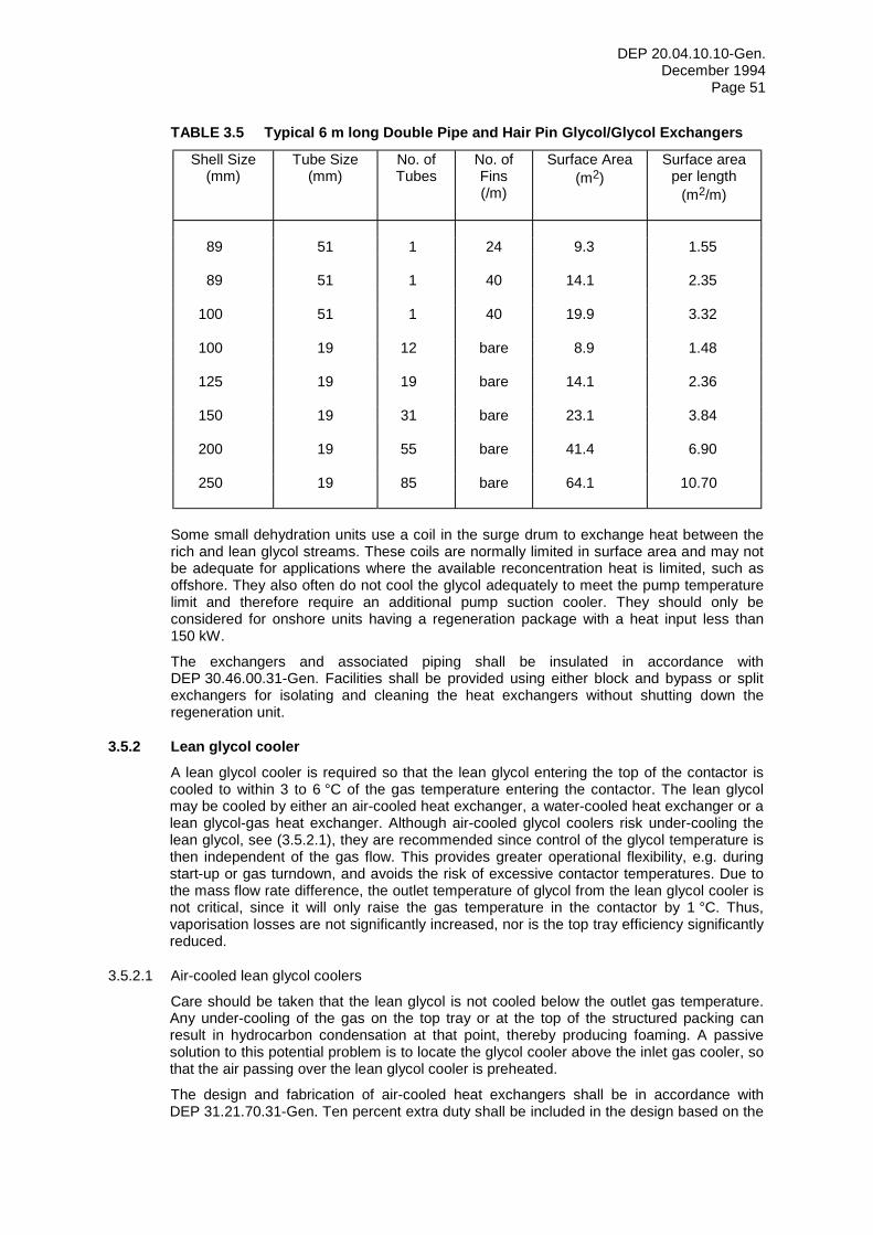
DEP 20.04.10.10-Gen. December 1994
Page 51
TABLE 3.5 Typical 6 m long Double Pipe and Hair Pin Glycol/Glycol Exchangers
Shell Size (mm)
Tube Size (mm)
No. of Tubes
No. of Fins (/m)
Surface Area (m2)
Surface area per length
(m2/m)
89 51 1 24 9.3 1.55
89 51 1 40 14.1 2.35
100 51 1 40 19.9 3.32
100 19 12 bare 8.9 1.48
125 19 19 bare 14.1 2.36
150 19 31 bare 23.1 3.84
200 19 55 bare 41.4 6.90
250 19 85 bare 64.1 10.70
Some small dehydration units use a coil in the surge drum to exchange heat between the rich and lean glycol streams. These coils are normally limited in surface area and may not be adequate for applications where the available reconcentration heat is limited, such as offshore. They also often do not cool the glycol adequately to meet the pump temperature limit and therefore require an additional pump suction cooler. They should only be considered for onshore units having a regeneration package with a heat input less than 150 kW.
The exchangers and associated piping shall be insulated in accordance with DEP 30.46.00.31-Gen. Facilities shall be provided using either block and bypass or split exchangers for isolating and cleaning the heat exchangers without shutting down the regeneration unit.
3.5.2 Lean glycol cooler A lean glycol cooler is required so that the lean glycol entering the top of the contactor is cooled to within 3 to 6 °C of the gas temperature entering the contactor. The lean glycol may be cooled by either an air-cooled heat exchanger, a water-cooled heat exchanger or a lean glycol-gas heat exchanger. Although air-cooled glycol coolers risk under-cooling the lean glycol, see (3.5.2.1), they are recommended since control of the glycol temperature is then independent of the gas flow. This provides greater operational flexibility, e.g. during start-up or gas turndown, and avoids the risk of excessive contactor temperatures. Due to the mass flow rate difference, the outlet temperature of glycol from the lean glycol cooler is not critical, since it will only raise the gas temperature in the contactor by 1 °C. Thus, vaporisation losses are not significantly increased, nor is the top tray efficiency significantly reduced.
3.5.2.1 Air-cooled lean glycol coolers
Care should be taken that the lean glycol is not cooled below the outlet gas temperature. Any under-cooling of the gas on the top tray or at the top of the structured packing can result in hydrocarbon condensation at that point, thereby producing foaming. A passive solution to this potential problem is to locate the glycol cooler above the inlet gas cooler, so that the air passing over the lean glycol cooler is preheated.
The design and fabrication of air-cooled heat exchangers shall be in accordance with DEP 31.21.70.31-Gen. Ten percent extra duty shall be included in the design based on the
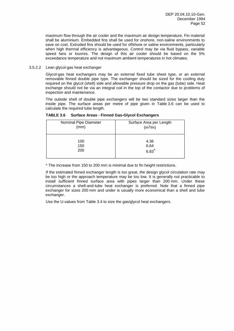
DEP 20.04.10.10-Gen. December 1994
Page 52
maximum flow through the air cooler and the maximum air design temperature. Fin material shall be aluminium. Embedded fins shall be used for onshore, non-saline environments to save on cost. Extruded fins should be used for offshore or saline environments, particularly when high thermal efficiency is advantageous. Control may be via fluid bypass, variable speed fans or louvres. The design of this air cooler should be based on the 5% exceedance temperature and not maximum ambient temperatures in hot climates.
3.5.2.2 Lean glycol-gas heat exchanger
Glycol-gas heat exchangers may be an external fixed tube sheet type, or an external removable finned double pipe type. The exchanger should be sized for the cooling duty required on the glycol (shell) side and allowable pressure drop on the gas (tube) side. Heat exchange should not be via an integral coil in the top of the contactor due to problems of inspection and maintenance.
The outside shell of double pipe exchangers will be two standard sizes larger than the inside pipe. The surface areas per metre of pipe given in Table 3.6 can be used to calculate the required tube length.
TABLE 3.6 Surface Areas - Finned Gas-Glycol Exchangers
Nominal Pipe Diameter (mm)
Surface Area per Length (m2/m)
100 4.36 150 6.64 200 6.83*
* The increase from 150 to 200 mm is minimal due to fin height restrictions.
If the estimated finned exchanger length is too great, the design glycol circulation rate may be too high or the approach temperature may be too low. It is generally not practicable to install sufficient finned surface area with pipes larger than 200 mm. Under these circumstances a shell-and-tube heat exchanger is preferred. Note that a finned pipe exchanger for sizes 200 mm and under is usually more economical than a shell and tube exchanger.
Use the U-values from Table 3.4 to size the gas/glycol heat exchangers.
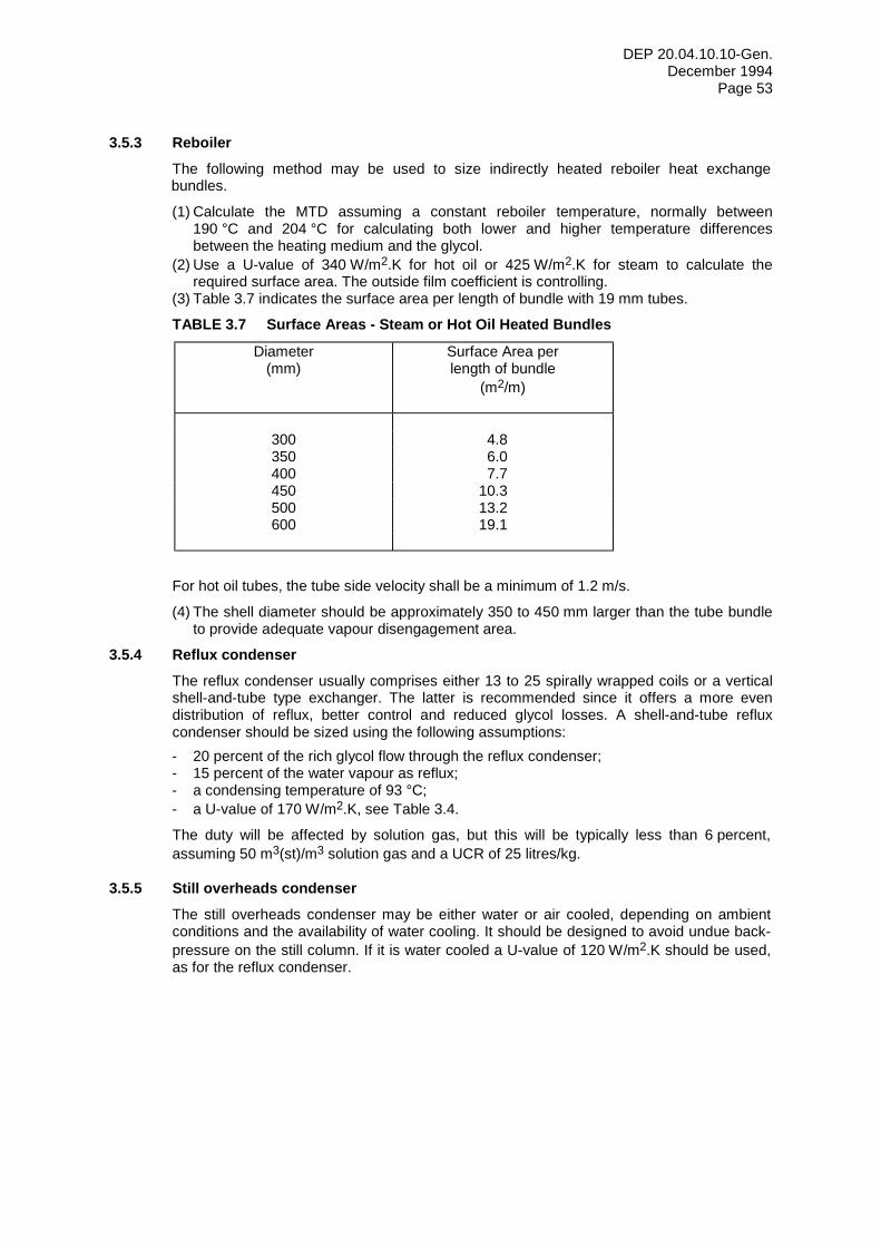
DEP 20.04.10.10-Gen. December 1994
Page 53
3.5.3 Reboiler The following method may be used to size indirectly heated reboiler heat exchange bundles.
(1) Calculate the MTD assuming a constant reboiler temperature, normally between 190 °C and 204 °C for calculating both lower and higher temperature differences between the heating medium and the glycol.
(2) Use a U-value of 340 W/m2.K for hot oil or 425 W/m2.K for steam to calculate the required surface area. The outside film coefficient is controlling.
(3) Table 3.7 indicates the surface area per length of bundle with 19 mm tubes.
TABLE 3.7 Surface Areas - Steam or Hot Oil Heated Bundles
Diameter (mm)
Surface Area per length of bundle
(m2/m)
300 4.8 350 6.0 400 7.7 450 10.3 500 13.2 600 19.1
For hot oil tubes, the tube side velocity shall be a minimum of 1.2 m/s.
(4) The shell diameter should be approximately 350 to 450 mm larger than the tube bundle to provide adequate vapour disengagement area.
3.5.4 Reflux condenser The reflux condenser usually comprises either 13 to 25 spirally wrapped coils or a vertical shell-and-tube type exchanger. The latter is recommended since it offers a more even distribution of reflux, better control and reduced glycol losses. A shell-and-tube reflux condenser should be sized using the following assumptions: - 20 percent of the rich glycol flow through the reflux condenser; - 15 percent of the water vapour as reflux; - a condensing temperature of 93 °C; - a U-value of 170 W/m2.K, see Table 3.4.
The duty will be affected by solution gas, but this will be typically less than 6 percent, assuming 50 m3(st)/m3 solution gas and a UCR of 25 litres/kg.
3.5.5 Still overheads condenser The still overheads condenser may be either water or air cooled, depending on ambient conditions and the availability of water cooling. It should be designed to avoid undue back-pressure on the still column. If it is water cooled a U-value of 120 W/m2.K should be used, as for the reflux condenser.
DEP 20.04.10.10-Gen. December 1994
Page 54
3.6 SURGE DRUM
The surge drum should be sized to provide the following: - a retention time not less than 20 minutes between low and normal levels, based on the
design circulation rate; - a reasonable length of time between glycol additions; - sufficient volume to accept the glycol drained from the reboiler to allow repair or
inspection of the heating coil.
It can be conveniently vented to the reboiler but a small amount (typically 0.4 m3/h) of nitrogen or dry fuel gas purge is needed to prevent water vapour from the reboiler flowing through the vent line and being absorbed by the glycol in the surge drum. If it is not located directly below the reboiler, it shall be provided with a separate purge gas supply.
Provisions shall be made for: - make-up of the glycol inventory from a drum using a simple air driven pump with a
check valve and filter; - batch addition of chemicals to the glycol surge drums, e.g. for pH control, corrosion
inhibition, etc. - metering the quantity of glycol added to the surge drum.
The surge drum shall meet the requirements of DEP 31.22.10.32-Gen. or DEP 31.22.20.31-Gen. It shall be fabricated from carbon steel with a minimum corrosion allowance of 3 mm. It shall be insulated in accordance with DEP 30.46.00.31-Gen.
DEP 20.04.10.10-Gen. December 1994
Page 55
3.7 GLYCOL FLASH VESSEL
The glycol flash vessel is used to remove gaseous hydrocarbons that have been absorbed or entrained with the glycol as well as recovering the spent gas from gas-glycol powered pumps. It also serves to separate any liquid hydrocarbons from the glycol to prevent them from entering the reboiler and causing fouling, foaming and flooding.
Both sulphur compounds and carbon dioxide are very soluble in water/glycol mixtures and react to some degree with glycols. Degassing in the flash vessel before the still column reduces their concentration and reduces high temperature corrosion. Degassing is more efficient if the rich glycol is first pre-heated, as shown in Figure 2.1. Pre-heating, to about 60 or 70 °C, also reduces its viscosity.
When gas-glycol powered pumps are used, see (3.10), the operating pressure of the flash vessel must be compatible with the allowable backpressure on the pumps. The general requirement is for a maximum system backpressure of 15 percent of the contactor operating pressure. Thus, for 7 MPa contactor pressure the flash vessel must operate at a pressure lower than 1 MPa.
The vessel should be designed in accordance with DEP 31.22.05.11-Gen. It should normally be horizontal and sized for a liquid hold-up of 30 minutes in the inlet compartment. Since liquid capacity is limiting and gas rates are low, it should usually be designed to operate between about 60 to 80 percent full.
To separate liquid hydrocarbons from glycol, a bucket or trough and weir design, see Figure 3.16, is recommended due to the simplicity of the controls for the small density difference between the collected hydrocarbons and the glycol. Two level controllers are required instead of an interface controller for a single weir design. With the recommended design, it is critical to set the glycol high level alarm in the glycol compartment below the level of the glycol overflow weir. Glycol would otherwise overflow into the hydrocarbon bucket and be lost. A baffle plate should be installed between the inlet and the condensate weir to evenly distribute the forward liquid flow and also retain any foam. The elevation difference (Z1) between NL and IL can be calculated from the equation:
Z1 = Z2 (ρg - ρL2) / (ρL1 - ρL2)
where: - Z2 is the elevation difference between NL and the glycol overflow weir; - subscripts L1 and L2 denote condensate and glycol respectively.
The glycol flash vessel shall meet the requirements of DEP 31.22.10.32-Gen. or DEP 31.22.20.31-Gen. It shall be fabricated from carbon steel with a minimum corrosion allowance of 3 mm. It shall be insulated for heat conservation in accordance with DEP 30.46.00.31-Gen.
Plugging can occur at the glycol draw-off point, which is exacerbated by being the lowest point of the system and the small glycol volumes involved. An accessible strainer is required upstream of the glycol dump valve and connections should be provided to backflow the dump nozzle on the vessel in order to keep it working.
The condensate normally flows to the operational drains system. Gas may be routed to the LP flare, used as stripping gas, reboiler fuel or recompressed. In addition a blanket gas connection should be provided to ensure sufficient operating pressure in the glycol flash vessel.
DEP 20.04.10.10-Gen. December 1994
Page 56
3.8 CONDENSED OVERHEADS SEPARATOR
A condenser and three-phase separator should be installed in the vapour line from the regenerator still. The vapour and contaminated water are waste streams, hydrocarbon emissions or flaring/incineration are reduced by the amount of produced condensate. The 3-phase separator can be similar in design to the glycol flash vessel (3.7). Similarly to the overhead condenser, pressure losses should be minimised. Avoid undersizing the feed and gas outlet nozzles and restrictive inlet and de-entrainment outlet devices. Further processing of the outlet streams should also be considered with regard to environmental issues, see EP 94-0930.
DEP 20.04.10.10-Gen. December 1994
Page 57
3.9 FILTERS
Filters shall be located in a common area in order to limit areas subject to spillage/pollution. They shall be designed for rapid, simple and safe filter element replacement. Filter bodies shall be not more than 1.5 m high, space around the filters shall ensure accessibility for easy maintenance and the handling of fouled filter elements. A quick-closure lid with pressure safety device shall be used. The lid shall be easily removable by means of a rotating davit or a hinge with counterweight. Block, vent and drain valves shall be provided for each filter. Vent and drain connections shall be large enough to allow water flushing before opening for cleaning and maintenance. Control of flushing is required. The design shall be such that no gas can be trapped in the filter cover.
Filter elements shorter than 0.5 m shall be used to avoid crack formation by expansion. The high viscosity of glycol at low temperatures shall be taken into account in the design of the glycol filters.
The following steps shall be taken if the feed gas contains mercury: - replaceable filter elements shall be non-metallic to reduce the problem of disposal in
case they become contaminated; - special provisions shall be made for storage and disposal of used filter elements; - the possibility of mercury accumulation shall be borne in mind for all connections to the
filter. Drainage points are preferred to be vertical. In addition, since mercury migrates through gaskets, suitable drip pans or pits shall be constructed under the filters with a low point in which the mercury can be collected and sucked up with a vacuum truck. Aluminium or copper alloys shall not be used.
3.9.1 Particle filters Sock or pleated paper cartridge type glycol filters should be used to remove solid impurities over 5 µm in size before they cause fouling, foaming or plugging. Two full flow filters with change-over valves and no by-pass lines should be installed in parallel to permit continuous operation during change-out. The filters are installed in the rich glycol line downstream of the glycol-flash vessel. In addition a single full flow filter should be installed downstream of the glycol pump to intercept particles that may originate in the reboiler and eliminate the need for a specific filter upstream of any liquid distributor in the contactor, see (3.3.5). Filtration upstream of the liquid distributor should remove particles having a size greater than one fifth of the smallest hole diameter, e.g. 0.2 x 4 mm, see (3.3.5).
Frequent filter changes may be needed during start-up or when neutralisers are added to the system to control the glycol pH. 25 µm cartridges can be used for initial start-up, then changed to 5 µm cartridges. The change-out and transport of spent cartridges for safe disposal can give rise to a significant logistical and hygiene problem.
The filters shall be depth type filter elements, since these have a longer service life and greater efficiency than barrier filters. If the glycol is contaminated with condensate, this will dissolve the impregnating agent, which reduces the life of the surface filters. The filters should have a holding capacity of at least 20 kg, but preferably 50 kg. Alternatively, two filters in series may be specified, the first a cleanable filter down to 50 µm followed by a 5 µm filter. The coarse filter will prolong the life of the fine filter, possibly improving lifecycle cost. The maximum pressure drop across the filter shall be limited to 170 kPa. A differential pressure gauge with alarm shall be fitted between the filter inlet and outlet. It shall be possible to exchange the gauge during operation. The filter elements shall be designed for a pressure difference of at least 200 kPa. The flow through the filter shall not exceed 44 litre/min/m2, based on the external area of the filter elements, and each filter shall be sized for 120 percent of the design flow. The glycol filter elements should be changed every 3 to 6 months, even if the pressure drop does not increase across them, to prevent accumulation of sludge.
DEP 20.04.10.10-Gen. December 1994
Page 58
3.9.2 Activated carbon filters An activated carbon filter can effectively remove most foam promoting compounds such as well-treating chemicals, compressor oils and other troublesome organic impurities in the glycol. It should be installed downstream of the particle filters in the rich glycol line. For glycol flow rates less than about 1.25 litres/s (4.5 m3/hour), a full flow filter is normally used. Sidestream filtration with not less than 10 percent flow or 1.25 litres/s can be used for higher glycol flow rates. This flowrate must be verifiable during normal system operation. Sidestream filtration may be achieved with a three-way control valve equipped with a mechanical stop for the design flow rate.
Only one carbon filter with block valves and a bypass should be installed, since it will not harm the glycol system to take the filter out of service to change the elements. Carbon filters are usually sized to give a flowrate of 2.5 to 5.0 m3/h per m2 of filter cross sectional area.
The method for determining the need to change the activated carbon filters differs from that of particle filters. Due to the method of adsorption in the carbon elements, the differential pressure will remain constant even though the filters are no longer active. The elements should thus be changed when the clarity of the glycol deteriorates or when the glycol analysis indicates a high hydrocarbon content.
If the feed gas contains mercury, it may also be necessary to install a sulphur-impregnated activated carbon filter in the vapour outlet line downstream of the condensed overheads separator.
DEP 20.04.10.10-Gen. December 1994
Page 59
3.10 GLYCOL CIRCULATION PUMPS
Glycol pumps shall be selected in accordance with DEP 31.29.02.11-Gen. They shall be classified as essential duty, continuous operation and non-corrosive service under the definition of terms of DEP 31.29.02.11-Gen. Reciprocating pumps shall meet the requirements of DEP 31.29.12.30-Gen.
Glycol circulation pumps may be electric motor driven, steam, gas or gas-glycol powered. The pumps shall be sized to provide a minimum of 25 percent excess capacity. Two glycol pumps shall be provided each designed for the full glycol flow. The pumps shall be piped in parallel: one running and one standby. The pumps shall be mounted in an accessible location and the piping arranged such that the pumps are easily removable.
A strainer shall be installed in the glycol line upstream from each pump. The strainer shall be easily removable for cleaning. A PSV shall be provided at each pump discharge, with the relief flow returning to the surge drum.
Pumps shall have forged or cast steel fluid ends, AISI 420 stainless steel plungers, piston rods and valve and valve seats. Piston rods and plungers shall have D-gun applied stellite or ceramic hard facing where packing wear may occur.
Pumps utilising conventional drives are normally reciprocating multiplex type. A maximum piston speed of 0.6 m/s should be used since the lubricating properties of glycol are poor. The maximum fluid temperature for multiplex pumps is typically 120 °C.
Gas-glycol powered pumps utilise the rich glycol under pressure plus supplementary gas from the contactor to furnish the driving energy. Since the pumping rate is proportional to the volume of the return glycol and gas, the pumping rate is easily controlled by adjusting the gas flow and no surge drum level control is required. For a 7 MPa contactor pressure, about 40 m3(st) of gas is required per m3 of glycol flowing to the glycol flash vessel. The glycol flash vessel may operate at up to 15 percent of the contactor pressure less an allowance for friction. The friction component is significant at lower pressures and difficulty has been experienced on units with a contactor pressure less than 1.5 MPa. For gas-glycol powered pumps to be economically attractive this gas should be used as fuel or compressed. On locations where there is a suitable compressor, gas-glycol powered pumps are often used. Typical maximum fluid temperatures for gas-glycol powered pumps are 65 °C for standard trim and 93 °C for high temperature trim.
DEP 20.04.10.10-Gen. December 1994
Page 60
3.11 PIPING, VALVES AND FITTINGS
Piping, valves and fittings shall be in accordance with DEP 31.38.01.11-Gen., and DEP 31.38.01.31-Gen. The applicable piping classes (DEP 31.38.01.12-Gen. or DEP 31.38.01.15-Gen.) shall be as specified by the Principal. The number of flanges in the piping system shall be kept to a minimum. Flanges should be provided only to facilitate maintenance and inspection or where construction or process conditions dictate. The number of field welds shall be kept to a minimum. Allowance shall be made for site adjustment due to misalignment of the prefabricated pipework and foundations. Piping systems shall have sufficient flexibility to allow for thermal expansion to prevent failure of components due to over-stress, leakage, etc. All pipework shall be arranged so that all maintainable items of equipment are accessible and capable of being removed.
In the piping design, vibrations due to pulsating flows shall be taken into consideration by checking the mechanical response of the pipework to pumping pulsations. Improperly designed pipework to and from the glycol circulation pumps can lead to severe pulsations. The velocity in the suction line (from the glycol/glycol heat exchanger) shall not exceed 0.1 to 0.5 m/s. The discharge line velocity should not exceed 1.5 to 2.0 m/s. Gas bladder type pulsation dampers should be fitted to the suction and discharge of the glycol circulation pumps.
A particular hazard for gas dehydration systems is gas blow-by on failure of the contactor LCV. Gas blow-by is most significant during start-up when there is no dissolved gas in the glycol and can lead to high transient pressures upstream of the glycol flash vessel. A PSV sized for gas blow-by shall be installed on the glycol flash vessel. Peak transient pressures between the contactor LCV and glycol flash vessel are influenced by a number of factors: - glycol temperature and amount of dissolved gas; - flow coefficient of the LCV; - relative positions of the LCV, reflux condenser and bypass TCV, glycol/glycol heat
exchanger and glycol flash vessel; - pipe lengths and sizes between LCV and glycol flash vessel; - flow coefficient of reflux condenser bypass TCV in the operating position; - flow characteristic and location of any relieving device, usually at the glycol flash vessel.
The Principal should be consulted for advice on commercially available transient flow simulators that are able to predict backpressures upstream of the glycol flash vessel. From the results, intermediate design pressures may be selected for the piping, the reflux condenser and the glycol/glycol exchanger upstream of the flash vessel. Alternatively, for relatively low inlet gas pressures, it may be appropriate to design the piping and equipment upstream of the flash vessel for the design pressure of the contactor. An additional PSV should not be installed upstream of the glycol/glycol exchanger due to the high rate of pressure build-up during a transient.
U-bends and low points should be avoided in still column vent lines, since they will collect water and increase the backpressure. U-bends and low points should also be avoided in the piping between a separate inlet gas separator and the contactor to minimise liquid accumulation and subsequent slugging. The piping between this separator and the contactor should be as short as possible.
The overhead vapour line from the glycol still to either the vapour compression/incinerator (sour gas) or regenerator condenser (sweet gas) and the relief line to the vent line shall always slope downwards to either the compressor suction drum, the incinerator, regenerator condenser or vent line. The overhead vapour line shall be AISI 316L stainless steel. Where applicable the overhead vapour line and the overhead condenser shall be insulated and winterized to prevent the freezing of water and hydrocarbons.
The elevation of the regenerator and surge tank shall ensure adequate head for the glycol/glycol heat exchangers and the glycol circulation pumps. Attention should also be given to the lean glycol piping from the glycol/glycol exchangers and the surge tank to minimise vapour lock. If a stripping column is installed, it shall be designed such that the liquid level in the column shall never be above the stripping gas inlet connection. The
DEP 20.04.10.10-Gen. December 1994
Page 61
maximum level in the surge tank should be designed taking into consideration the potential level in the stripping column.
With the larger surface areas recommended on the lean/rich glycol heat exchangers, some still feed vaporisation will occur. Feed piping to the still should be designed for this two-phase flow to prevent surging which could upset the still operation, possibly causing flooding and glycol carry-over. The glycol flash vessel rich glycol LCV should be installed as close as possible to the still feed nozzle to minimise vaporisation.
Valves should be located with the valve body horizontal and the actuator located above the valve. Valves shall be located in such a way that the hand wheel or stem will not obstruct walkways or platforms. Valves should be easily accessible for operation and maintenance.
A check valve shall be installed as close to the injection point of the contactor as possible to prevent a reversed flow and gas entering the glycol injection line in the event of a pump failure or line rupture. The check valve shall be easily accessible.
Relief valves shall be installed in an accessible location on the glycol contactor below the mist mat. A top platform may be required.
DEP 20.04.10.10-Gen. December 1994
Page 62
3.12 COLDFINGER
Application of the Coldfinger process requires an additional pump, with a spare, to recycle glycol from the Coldfinger collection trough in the surge drum to the still column feed. Changes to the following hardware are also required: - still column; - reboiler; - surge drum.
The loading of the still column and the duty of the reboiler are increased by the recycle stream from the surge drum. The surge drum needs to be well insulated to maintain a temperature close to that of the reboiler. It must also accommodate the Coldfinger heat-exchanger bundle and liquid collection trough, which occupies space that is not available for liquid surge.
The Principal should be consulted for further advice on possible applications of the Coldfinger process since there is only limited information available on its performance.
DEP 20.04.10.10-Gen. December 1994
Page 63
3.13 GAS STRIPPING
Stripping gas cannot be condensed from the still overheads and it also reduces the amount of hydrocarbons recovered in the condensed overheads separator. "End-of-pipe" facilities, e.g. incinerators, shall have sufficient capacity for the stripping gas in addition to vapours from the reboiler and glycol flash vessel. If there is a continuous need for lean glycol concentrations in excess of 98.75 percent, more environmentally friendly processes should be considered, e.g. Coldfinger or DRIZO. Stripping gas should be considered only for the following conditions: - intermittent use, e.g. to increase the glycol concentration during peak rate periods or
during extremely hot weather when utilities become limiting; - as a contingency to cater for higher than design gas temperatures, higher flow rates, or
reduced heat availability for glycol regeneration.
3.13.1 Gas rate Using counter-current stripping in a packed column, the quantity of stripping gas required to achieve a given concentration can be reduced by a factor of five or more compared with injecting gas into the reboiler. Figure 3.17 shows the effect of counter-current stripping on glycol concentration.
The amount of stripping gas should be kept to a minimum for economic and environmental reasons. Normal operation should require less than 7 m3(st) stripping gas per m3 of glycol circulated. However, a maximum design rate of 35 m3(st)/m3 should not be exceeded, to prevent the possibility of column flooding.
A rotameter shall be used for measuring the flow of stripping gas. Normal rotameters may be used up to a maximum fuel gas design pressure of 0.7 MPa. Above this pressure rotameters of the stiffened type shall be used.
3.13.2 Stripping column The stripping column allows the stripping gas to make intimate contact with the lean glycol. Referring to Figure 2.1, note that the stripping column is installed between the reboiler and the surge drum. The stripping gas thus strips the water remaining in the lean glycol and is not diluted by the water previously removed in the reboiler.
3.13.2.1 Design method
The stripping column mechanical design shall be the same as the still column (3.4.2). It shall be fabricated from carbon steel with a minimum corrosion allowance of 3 mm. The column shall be insulated for heat conservation in accordance with DEP 30.46.00.31-Gen.
3.13.2.2 Column diameter
The stripping column should be designed for between 70 and 75 percent of flood. The size of the column can be calculated as for other packed columns. However, since the design conditions are always the same, the cross-sectional area of the stripping column can be found from Figure 3.18.
3.13.2.3 Column height
The height of the stripping column is governed by the same variables as the height of other columns; i.e. the taller the packing, the more theoretical trays available.
Due to the low gas rates involved and the nature of stripping/absorbing, a greater packing height is required per theoretical tray than in the still column. Instead of 0.3 to 0.75 m per theoretical tray, the values in stripping columns are typically 0.6 to 0.9 m.
DEP 20.04.10.10-Gen. December 1994
Page 64
3.13.3 Stripping gas supply Stripping gas may be taken from either the glycol flash vessel or from the fuel gas. For a direct fired reboiler, stripping gas may be taken downstream of the drain pot and from the top of the fuel gas line to the burner of the reboiler. To prevent accumulation and freezing of liquid, there shall be no low points in the stripping gas line to the surge drum. There shall be a shut-off valve incorporated in the stripping gas line upstream of the surge drum to prevent liquid from the reboiler entering the stripping gas line.
A heater may be required upstream of the stripping column to ensure that the stripping gas is dry. The need for and duty of this heater depend on the gas composition and the ambient temperature. The heater shall consist of a removable coil in either the reboiler or the surge drum.
DEP 20.04.10.10-Gen. December 1994
Page 65
3.14 AZEOTROPIC STRIPPING (DRIZO)
The DRIZO process requires additional hardware and modifications to the standard equipment hardware, as shown in Figure 2.2 and listed below: - still column; - stripping column; - still overheads condenser and separator; - glycol flash vessel overheads condenser and separator (optional extra); - solvent pumps (extra); - solvent heater (extra).
One simplification is the elimination of activated carbon filters. BTEX components would flood the carbon bed making them ineffective in removing degradation products.
The DRIZO process may lead to an approximate doubling of the gas stream and a higher concentration of BTEXs in the waste water stream.
The Principal should be consulted for further advice on possible applications of the DRIZO process since there is only limited experience available on its performance.
3.14.1 Still column The still column is similar to that in (3.4.2) but allowance is required for the solvent loading. A demister mat may be installed above the reflux condenser to reduce entrainment losses. This causes an increase in backpressure, but can probably be accepted in view of the higher glycol concentration.
3.14.2 Stripping column The stripping column is similar to that in (3.13.2) but takes account of the different properties and flow rates.
3.14.3 Still overheads condenser and separator These should be similar in design to those already described in (3.5.4) and (3.5.5). The quantity of condensed hydrocarbon will, however, be greater due to the recovery of condensate from the glycol flash vessel and condensation of additional BTEX components due to absorption by the solvent.
3.14.4 Glycol flash overheads condenser and solvent recovery drum These may be placed downstream of the glycol flash vessel vapour outlet to recover C5+ components which reduces solvent losses. The condensed liquid stream flows to the still column and is added to the solvent extraction process.
3.14.5 Solvent pumps Two full-flow solvent pumps are required to overcome the backpressure of the solvent heaters and stripping column.
3.14.6 Solvent heaters A heat exchanger using lean glycol leaving the surge drum heats the solvent downstream of the solvent pump. This is followed by an electric heater upstream of the stripping column to superheat the solvent to above 150 °C.
DEP 20.04.10.10-Gen. December 1994
Page 66
3.15 ELECTRICAL REQUIREMENTS
All electrical equipment shall be suitable for operation in a Zone 2 hazardous area. If an electrically heated reboiler is used, it should be suitable for operation in a Zone 2 hazardous area, gas group IIA, temperature class T3.
The complete electrical installation shall be designed and constructed in accordance with DEP 33.64.10.10-Gen., and the relevant equipment requisition sheets.
DEP 20.04.10.10-Gen. December 1994
Page 67
3.16 MECHANICAL REQUIREMENTS
3.16.1 Mounting of the glycol system The contactor and inlet gas separator are not usually skid mounted, in which case they shall be provided with lifting lugs. Other glycol system equipment may be skid mounted. The equipment shall be arranged on each skid to provide safe personnel access for ease of maintenance and operations. The arrangement of the skids is specific to the capacity and size of the total process plant and its location.
Skids shall be of rigid construction which will not distort during shipping, loading or operation. Skids and equipment supports shall be designed for the maximum operating weight of the equipment. Transport and lifting conditions shall use an acceleration of 0.5 g. For onshore service, four lifting lugs shall be provided to enable skids to be lifted as a four point single lift load. Skids and equipment supports shall be ready for mounting on existing foundations and shall include foundation bolts and shims.
All skids shall be pre-piped and wired before delivery. All customer connections shall be brought to the skid edge. Equipment shall not extend beyond the edge of the skid.
All equipment shall be furnished with a drain rim baseplate designed to collect any spillage or leakage of liquid. The baseplates shall be fitted with a 50 mm flanged drain connection.
3.16.2 Ladders, walkways and platforms Ladders and platforms shall be provided for access to all instruments, controls, manholes, valves and work areas for routine operation and regular maintenance.
Ladders shall be designed generally in accordance with Standard Drawing S 28.011. The following requirements shall also be met: - ladders and walkways shall be fabricated from carbon steel; - the minimum clear walking space on walkways shall be 600 mm wide; - if galvanised open type grating is required it shall be specified on the requisition; - ladders shall have a minimum width of 500 mm.
All vertical vessels exceeding 1.8 m in diameter shall be equipped with support clips on the top head to permit the future addition of a top platform. All support clips shall be shop welded to vessels before any stress relieving.
3.16.3 Hot insulation and painting Where insulation of piping and equipment for the protection of personnel is required, insulation shall be applied to a height of 2.1 m above walking levels and laterally 400 mm from any walkway space.
All carbon steel equipment shall be painted or coated in accordance with DEP 30.48.00.31-Gen.
3.16.4 Preparation for shipment All equipment and instrumentation shall be tagged as appropriate with nameplates in accordance with Standard Drawings S 10.114 and S 37.601.
All equipment shall be preserved, sealed, packed and/or crated to withstand adverse conditions occurring during the mode of transport to the specified location. The preparation shall be suitable for at least 6 months storage from the time of shipment requiring a minimum of disassembly prior to operation.
Each item of equipment on the skid shall be securely anchored to the skid and all unassembled items for shipment shall be tagged and secured to the skid. All pipework must be adequately supported during shipment.
Control valve heads shall be removed, tagged and crated in waterproof boxes securely strapped to the skid for shipment.

DEP 20.04.10.10-Gen. December 1994
Page 68
All openings, control valve stems and any other item subject to damage or corrosion shall be protected with wood or metal covers and sealed with waterproof tape. Flanged openings shall be provided with metal covers of 5 mm minimum thickness and synthetic rubber gaskets. At least 4 full-diameter bolts shall be used for flanged openings. For studded openings all studs and nuts needed for intended service shall be used for securing closures.
Any unpainted finished surfaces shall be coated with a suitable rust preventative. Threaded openings except telltale holes in nozzle reinforcing pads and saddles shall be protected with steel caps or solid shank steel plugs. Non-metallic plugs or caps shall not be used.
Suitable supports shall be provided for internal parts which might become damaged during shipment. These shall be conspicuously marked for easy identification and removal at site.
DEP 20.04.10.10-Gen. December 1994
Page 69
4 UPGRADING OF GAS DEHYDRATION SYSTEMS If the required gas dewpoint or water content specification fails to be met due to a design deficiency or a change in flow conditions, one or more parts of the dehydration system may require upgrading. This section, though not exhaustive, includes a number of upgrading tips to guide the designer. The term upgrading includes improved specification such as to reduce water content, and debottlenecking such as increasing the gas throughput. More detailed guidance for specific installations is available from the Principal.
4.1 INLET SEPARATION
Improved gas inlet separation may be used to lower the water content of the dried gas and/or increase the gas throughput.
The inlet separator is sometimes overloaded relative to the contactor, e.g. a contactor with structured packing may have an integral separator, but without a swirltube separation deck, see Figure 3.4. In this case the advice contained in Appendix X of DEP 31.22.05.11-Gen. regarding the retrofit of either a swirldeck or vane pack may be appropriate.
If the inlet separator is a separate vessel, then the guidelines given in report EP 93-1165 may be appropriate. Adding to or increasing the duty of an inlet cooler is often the most economic method of upgrading a gas dehydration system provided that the temperature does not enter the hydrate formation region. The effect of this measure on the phase envelope of the sales gas should be checked.
4.2 CONTACTOR
A contactor may lack sufficient packing height or number of trays to achieve the desired water dewpoint. In a contactor without an integral separator, a possible solution is to install a number of in-line mixing elements in the feed pipe and to spray part of the rich glycol from the contactor bottom onto these elements in co-current flow, see Figure 4.1. In this way one equilibrium stage may be created, thus unloading the column.
There are three other upgrading possibilities that could be applied, namely: - changing from bubble cap trays to structured packing; - changing from bubble cap to swirltube trays; - changing from structured packing to swirltube trays.
4.2.1 Changing from bubble cap trays to structured packing Many contactors have been upgraded in this way. Subsequent operation has been found to be satisfactory provided hardware or operational changes are made to ensure the following are satisfied: - upstream separation; - gas distribution using a chimney tray; - uniform liquid distribution; - minimum liquid superficial velocity; - downstream de-entrainment.
Existing bubble cap trayed contactors have sometimes been found to be operating with chimney tray riser areas less than that recommended in (3.3.1). When upgraded with structured packing the old chimney tray should be replaced with one having a riser area of 15 to 20 percent of the column cross-sectional area.
For upgrading contactors without an integral separator, there may be insufficient space for a chimney tray. A spider inlet pipe with downward blowing vapour holes in combination with a vapour distribution tray may be a possible solution.
Redundant tray supports should be ground down to within at least 5 mm of the contactor wall. It is usually possible to fix the packing support grid and the liquid distributor to existing attachments. An allowance of 100 mm should be made for the packing support grid. The
DEP 20.04.10.10-Gen. December 1994
Page 70
packing support may be supported on a chimney tray or on the support of the bottom tray. Similarly the liquid distributor may be attached to the top tray support.
It is often possible to install more packing height than recommended in Figures 3.3 and 3.4 by reducing the space above and/or below the packing. This will be at the expense of some capacity, which may be acceptable for an upgrade.
4.2.2 Changing from bubble cap to swirltube trays The spacing of trays could be made the same by using the existing support rings. The integral separation swirldeck/liquid distributor and secondary demister at the top of the column (Figures 3.5 and 3.6) would, however, take up the space previously occupied by the top bubble cap tray. This could make this type of upgrade impractical unless the column could be made operable with one or more of the following: - upstream co-current contacting, see (4.2); - one less tray; - higher glycol circulation rate; - greater glycol concentration; - the integral de-entrainment device replaced by a separate downstream separator.
A further problem is the probable undersize of existing nozzles.
4.2.3 Changing from structured packing to swirltube trays The greatest problem will be the lack of existing support rings for the trays. Welding new support rings may not be practical, particularly if the contactor would require post-weld heat treatment. Supporting all of the trays on the old packing support ring via spacers (between the trays) may also not be acceptable due to the total weight of the heavy swirltube trays and/or sealing difficulties. The column height and nozzle sizes are also likely to present problems but less so than for (4.2.2).
4.3 GLYCOL REGENERATION CIRCUIT
The debottlenecking of a contactor necessitates a corresponding check of the capacities of all elements of the glycol regeneration circuit. This will often confirm that some of the existing hardware requires upgrading or replacing with larger units, e.g. pumps, heat exchangers, particle filters, though possibly not the sidestream activated carbon filter. The optimum solution could well be one that corresponds to a lower unit glycol circulation rate, which may not maximise gas capacity but which avoids a step increase in costs caused by the need to increase the capacity of a major hardware item.
If the available heat duty or allowable heat flux is limiting for the reboiler, it may not be possible to maintain the required temperature with an increased glycol circulation rate. An enhanced regeneration technique such as Coldfinger (2.2 and 3.12), gas stripping (2.4 and 3.13), or Drizo (2.5 and 3.14) should be considered to enable the rich glycol concentration to be achieved at a lower reboiler temperature. The simplest alternative is conventional gas stripping but this may be the worst solution for the environment, and is generally not recommended.
DEP 20.04.10.10-Gen. December 1994
Page 71
5 OPERATION AND MAINTENANCE OF GLYCOL DEHYDRATION SYSTEMS This section describes some of the more important operating and maintenance aspects of glycol dehydration systems including generalised start-up and shutdown procedures. The information is intended for use by both operating personnel and engineering staff.
5.1 PERFORMANCE CONSIDERATIONS
If a glycol dehydration system has been properly sized and installed, its performance is normally governed by five conditions:
- cleanliness of the inlet gas; - temperature and pressure of the inlet gas; - glycol circulation rate; - lean glycol concentration; - glycol purity.
5.1.1 Gas cleanliness The gas entering the contactor must be free of entrained liquids or solids, as emphasised in (3.2). Presence of contaminants can foul glycol systems. Deposits may occur on reboiler tubes causing tube failure, plugging of pump lines and reduced heat transfer. Solids entering the gas-glycol powered pump, when used, can rapidly wear the valves, plungers and packing.
5.1.2 Gas temperature and pressure The contact temperature and pressure has a substantial effect on performance of a glycol dehydration unit, see (2.9.2) and (2.9.3).
5.1.3 Glycol circulation rate If the desired dewpoint depression is to be achieved when the inlet gas temperature is higher than assumed in the design, the glycol circulation rate must be increased. This, in turn, increases the reboiler fuel consumption and, when used, the gas consumption of the gas-glycol powered pump. The design envelope of a glycol dehydration system shall therefore indicate the circulation rate against the gas inlet temperature at varying flowrate.
5.1.4 Glycol concentration If the design glycol concentration is not achieved, the dewpoint depression will be substantially decreased.
5.1.5 Glycol purity Operating and corrosion problems usually occur when the circulating glycol solution becomes contaminated. For long troublefree operation with a glycol solution, it is necessary to recognise potential contamination problems and to know how to prevent them. Some of the major problems are:
- oxidation; - thermal decomposition; - pH control; - salt contamination; - hydrocarbon contamination; - sludge; - foaming.
5.1.5.1 Oxidation
Oxygen may enter a system with the inlet gas, through unblanketed storage tanks and sumps, through the pump packing glands or via spilled or leaked glycol recovered from the drain rim base plates. Glycols will oxidise readily in the presence of oxygen and form
DEP 20.04.10.10-Gen. December 1994
Page 72
corrosive organic acids. Recovered glycol which is old or dirty or has been exposed to oxygen should not be returned to the glycol systems. Oxidation inhibitors may be used to prevent corrosion if oxygen contamination cannot be avoided.
5.1.5.2 Thermal decomposition
Excessive heat, which may result from one of the following conditions, will decompose the glycol to form corrosive compounds:
- if the reboiler temperature is too high, the film temperature outside of the tubes may be above the glycol decomposition temperature. Reboiler temperatures should be held at the minimum temperature necessary to achieve dehydration. The reboiler temperature should never be allowed to rise above the figures given in (3.4.1.2);
- a high heat flux rate, which is sometimes used to keep the reboiler cost low, can cause overheating. If this is the case, improved operation can be obtained by keeping the inlet gas temperature as low as possible and by using additional stripping gas which will allow lower reboiler temperatures;
- localised overheating is a serious problem caused by deposits of salt or tarry compounds on the reboiler heater or by poor flame direction which may impinge on the fire tubes. The flame pattern should be regularly checked, and corrected if necessary. Keeping the inlet gas free of entrained liquids or solids will minimise deposits.
5.1.5.3 pH control
The metallic corrosion rate increases rapidly with a decrease in the glycol pH. Organic acids resulting from the oxidation of glycol and thermal decomposition products or acid gases absorbed from the gas stream are the most troublesome corrosive compounds. The glycol pH should be regularly checked and kept between 6.5 and 8.0 by neutralising the acidic compounds with borax, ethanolamines, soda ash or other alkaline chemicals, see Appendix III and IV.
About 100 g of Methylethanolamine (MEA) per m3 of solution is usually sufficient to raise the pH from 6.5 to a safe level of about 7.3. Maintaining the pH around 7.3 may, however, require excessive addition of neutraliser. It is generally better to allow the pH to swing between the control limits. When the glycol pH is extremely low, the amount of neutraliser required can be determined by titration. The pH should not be raised above 8 to 8.5 because the glycol solution will tend to foam and emulsify more easily. An overdose of neutraliser will also precipitate a black sludge that will be suspended in the glycol solution. There is a high risk of over-dosing when using MEA, leading to a pH of greater than 10 causing cracking due to stress corrosion. Frequent filter changes are also required when pH buffers are being added.
If CO2 is present in the gas stream, sodium acetate or another base should be used instead of MEA to avoid reaction of CO2 with the MEA.
5.1.5.4 Salt contamination
Salt deposits accelerate equipment corrosion, reduce heat transfer in the reboiler tubes and affect specific gravity readings when a hydrometer is used to determine glycol-water concentrations. Troublesome salts are not removed with normal regeneration and accumulate in the glycol circuit. Salt water carry-over, either as slugs or fine mist, should be prevented by the use of an efficient separator upstream of the glycol contactor. However, when it is not possible to remove all the salt water from the gas stream, the removal of salt from the glycol is necessary. Several methods are available for salt removal from glycol such as vacuum distillation and electrodialysis.
Vacuum distillation of the rich glycol at a temperature no greater than 204 °C is recommended to reduce thermal degradation of the glycol. At this temperature and a pressure of 13 kPa, the overhead product will consist of 90-95 weight percent glycol, depending on the amount of salt present in the glycol. The concentration of reclaimed glycol should be similar to the circulating rich glycol and may be added directly to the rich glycol stream for reconcentration in the reboiler. The reclaimed glycol pH will be acidic and
DEP 20.04.10.10-Gen. December 1994
Page 73
should be brought up to 6.5-8.0 by adding an alkali such as alkanolamine. Vacuum distillation may be operated as a continuous or batch process, depending on the severity of the contamination and the volume of glycol to be purified.
The waste sludge from the vacuum unit must be disposed of in an environmentally acceptable manner.
Pretreatment of the glycol to reduce visocity and control pH is essential to ensure efficient operation of an electrodialysis unit and reduce problems that may occur at a later stage. The ideal temperature of the glycol for electrodialysis is between 25 and 40 °C. This improves the flow characteristics of the glycol and aids the conductivity of the solution. Temperatures above 45 °C are not recommended as they distort the polyethylene spacer. The pH of the glycol should be in the range between 7.0 and 8.0 and therefore some pH adjustment may be necessary. Viscosity is an important consideration in the use of electrodialysis units. Viscosities in excess of 7 mPa.s lead to excessive pressure drop through the membrane stacks because of the tortuous path through the spacers. There is a trade-off between viscosity and glycol concentration, as the conductivity is best at around 40-50 percent glycol.
5.1.5.5 Hydrocarbon contamination
Liquid hydrocarbons, resulting from carry-over with the inlet gas or from condensation in the contactor, increase glycol foaming, degradation and losses. Carry-over can be prevented by maintaining proper levels in the inlet separator and by keeping mist mats clean. Condensation in the contactor can be prevented by maintaining the inlet glycol temperature about 3 °C to 6 °C above the inlet gas temperature. If hydrocarbons enter the contactor, they must be removed in the glycol flash vessel or the activated carbon filter.
5.1.5.6 Sludge
An accumulation of solid particles and tarry hydrocarbons frequently collects in the glycol solution. This sludge is suspended in the circulating glycol and over a period of time, the accumulation becomes large enough to settle out. This process results in the formation of a black, sticky and abrasive gum which can cause erosion of pumps, valves and other equipment. It usually occurs when the glycol pH is low and becomes very hard and brittle when deposited on the contactor trays or packing, still column packing and other places in the circulating system. Proper solution filtration will prevent accumulation of sludge.
5.1.5.7 Foaming
This is more likely to be a problem with bubble cap trays due to the agitation created. Foaming increases glycol losses and reduces the capacity of the system. Entrained glycol will carry over the top of the contactor with the sales gas if a stable foam builds up on the trays. Foaming also causes poor contact between the gas and the glycol solution, which in turn leads to a poorer dewpoint depression.
Some foam promoters are:
- hydrocarbon liquids; - field corrosion inhibitors; - salt; - finely divided suspended solids.
Excessive turbulence and high vapour-to-liquid contacting velocities will usually cause the glycol solution to foam. This condition can be caused by deposits on the trays or gas rates greater than design.
The most satisfactory cure for foaming problems is proper care of the glycol solution. The most important measures to achieve this are effective gas cleaning ahead of the glycol system and proper filtration of the circulating solution. The use of anti-foaming agents (AF) will not solve an underlying problem. Addition of AF should be regarded as a temporary control until the foam promoters can be determined and eliminated.

DEP 20.04.10.10-Gen. December 1994
Page 74
The success of the AF is usually dependent upon when and how it is added. Some AFs, when added after the foam is generated, act as good inhibitors, but, when added before foam generation, act as good foam stabilisers, which makes the problem worse. Most AFs are deactivated within a few hours under high temperature and pressure conditions and their effectiveness can be dissipated by the heat of the glycol solution. AFs should generally be added continuously, a drop at a time, for best results. The use of a chemical feed pump will help meter the AF accurately and give better dispersion into the glycol solution. Water-soluble AFs are sometimes made more effective by diluting them before addition into the system. AFs with limited solubility should be added via the pump suction to ensure good dispersion in the glycol solution. If foaming is not a serious problem, the AF may be added in slugs of about 100 g when needed.
The addition of too much AF is usually worse than no AF at all. Excessive amounts sharply increase the foaming problem.
Appendix II contains a procedure that can be used to determine the best AF and the required dosage to control foaming.
5.2 OPERATING PROBLEMS
5.2.1 Analysis and control of the glycol solution Collecting of both lean and rich glycol samples shall be in accordance with EP 92-0980. The glycol sample should be sent to a qualified laboratory for testing at least quarterly. Appendix III describes the methods used for analysis of the glycol samples and Appendix IV contains guidelines that may be used to evaluate the test results.
5.2.2 Glycol losses Glycol losses can be a very serious and costly operating problem. Losses can occur by vaporisation, entrainment and mechanical leaks. Total glycol losses from a properly designed and maintained dehydration unit are typically between 20 and 60 litres/ million m3(st). The methods described herein may be used to reduce glycol losses.
5.2.2.1 Adequate cooling
A certain amount of glycol will always be vaporised in the sales gas stream. To avoid excessive vaporisation, the system shall be kept within the specified temperature limits. Cooling to within 3 to 6 °C of the inlet gas temperature of the lean glycol before it enters the contactor will minimise these losses.
5.2.2.2 Demister mat
Most entrainment associated with bubble cap trays is removed by a demister mat in the top of the contactor. These losses are typically about 10 litres/million m3(st). Excessive gas velocities and glycol foaming in the contactor will sharply increase losses. The demister should be examined if a high loss rate cannot be explained in any other way.
5.2.2.3 Vaporisation losses
Vaporisation losses in the regenerator still column can be reduced with satisfactory glycol condensation. The still condenser should be examined periodically. Glycol entrainment, and mechanical carry-over can be reduced by proper maintenance of the still. The still column overhead temperature is a good indicator of whether glycol is being lost as a vapour. If the temperature is above 100 °C at sea level, glycol must be present in the overhead vapours. Boiling point condensation curves contained in the GPSA Engineering Data Book indicate the vapour phase glycol concentration for estimating vaporisation losses.
5.2.2.4 Mechanical leaks
Mechanical leaks can be reduced by keeping the pump, valves and other fittings in good condition. A small drip of glycol can amount to significant daily losses.
DEP 20.04.10.10-Gen. December 1994
Page 75
5.2.2.5 Cold weather
During periods of extremely cold weather, excessive glycol losses may occur if the still column's thermal insulation, as recommended in (3.4.2), is inadequate or if reflux cooling is by an air cooled finned section, see (3.5.5). Low ambient temperatures, especially when coupled with a strong wind, will cause more vapours in the still column to condense and return to the reboiler where they are revaporised. This overloads the column with liquids which may cause it to flood. If this occurs, liquids are percolated out of the still with the water vapour. This can be overcome by reducing the load on the system. It should be noted that due to the cold weather, the gas temperature is likely to be below design which will mean that the system will be operating in a turndown mode.
5.2.3 Troubleshooting The most obvious indications of malfunction in glycol dehydration units are high water content in the sales gas stream and high glycol losses.
In the majority of cases, high water content in the sales gas stream is brought about by either insufficient glycol circulation or insufficient reconcentration of the glycol. Mechanical equipment malfunctions and operating conditions different from design are common causes. These upsets can sometimes be at least partially remedied by changes in process conditions and in mechanical operation.
Glycol consumption should be checked periodically to give another indication of how well the system is operating.
Appendix V lists a variety of contributing causes of system malfunction.
Suspect results from hygroscopic on-line monitors should be checked by direct measurement, see (10).
5.3 START-UP AND SHUT-DOWN PROCEDURES
The need to prepare a formal start-up and shut-down procedure for glycol dehydration systems will depend upon the size, location and type of application. Appendix VI contains general procedures and good practices which, if followed, should prevent repeated problems during start-up or shut-down. Sudden surges should be avoided in starting and shutting down the system to minimise the risk of glycol loss due to carry-over.
5.4 MAINTENANCE
Appendix VII contains a list of general items for periodic maintenance.
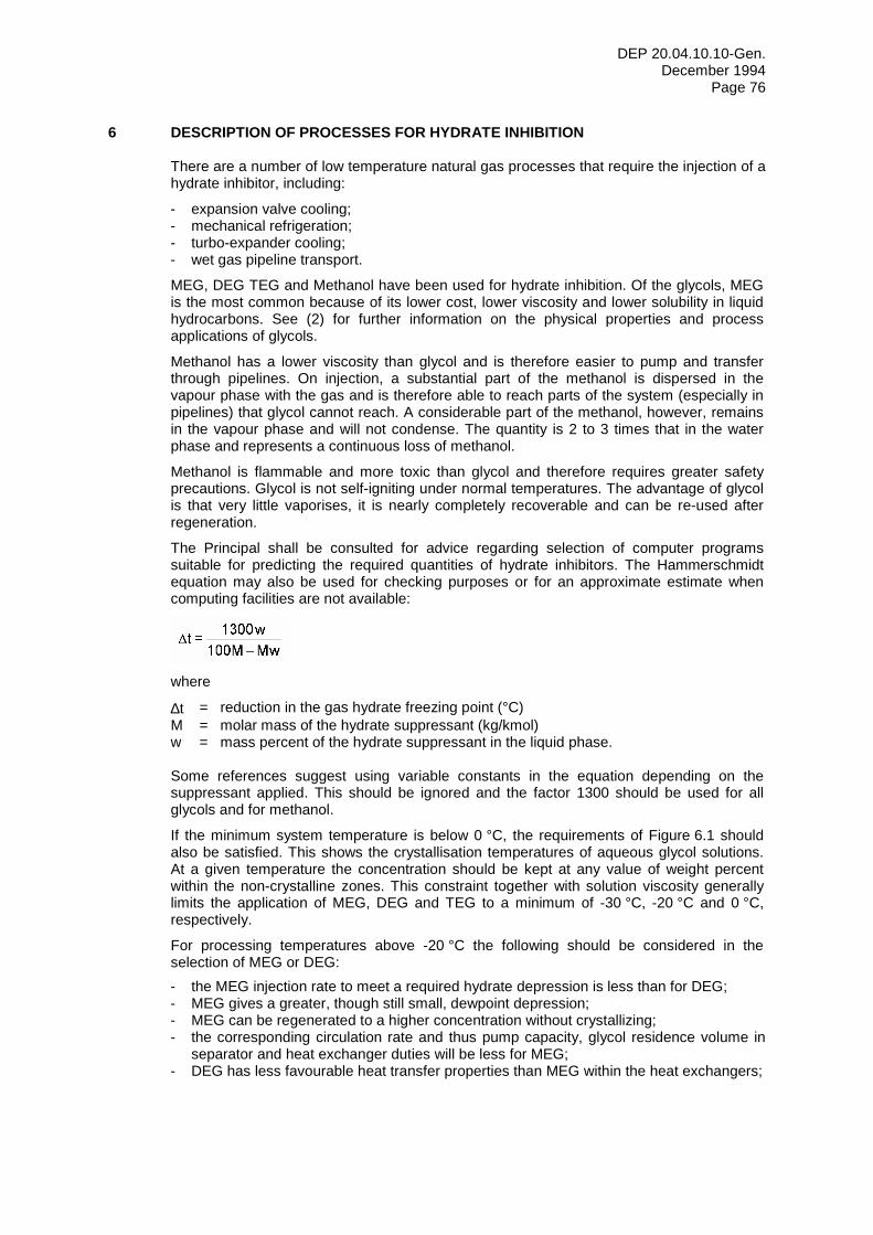
DEP 20.04.10.10-Gen. December 1994
Page 76
6 DESCRIPTION OF PROCESSES FOR HYDRATE INHIBITION There are a number of low temperature natural gas processes that require the injection of a hydrate inhibitor, including:
- expansion valve cooling; - mechanical refrigeration; - turbo-expander cooling; - wet gas pipeline transport.
MEG, DEG TEG and Methanol have been used for hydrate inhibition. Of the glycols, MEG is the most common because of its lower cost, lower viscosity and lower solubility in liquid hydrocarbons. See (2) for further information on the physical properties and process applications of glycols.
Methanol has a lower viscosity than glycol and is therefore easier to pump and transfer through pipelines. On injection, a substantial part of the methanol is dispersed in the vapour phase with the gas and is therefore able to reach parts of the system (especially in pipelines) that glycol cannot reach. A considerable part of the methanol, however, remains in the vapour phase and will not condense. The quantity is 2 to 3 times that in the water phase and represents a continuous loss of methanol.
Methanol is flammable and more toxic than glycol and therefore requires greater safety precautions. Glycol is not self-igniting under normal temperatures. The advantage of glycol is that very little vaporises, it is nearly completely recoverable and can be re-used after regeneration.
The Principal shall be consulted for advice regarding selection of computer programs suitable for predicting the required quantities of hydrate inhibitors. The Hammerschmidt equation may also be used for checking purposes or for an approximate estimate when computing facilities are not available:
where
∆t = reduction in the gas hydrate freezing point (°C) M = molar mass of the hydrate suppressant (kg/kmol) w = mass percent of the hydrate suppressant in the liquid phase. Some references suggest using variable constants in the equation depending on the suppressant applied. This should be ignored and the factor 1300 should be used for all glycols and for methanol.
If the minimum system temperature is below 0 °C, the requirements of Figure 6.1 should also be satisfied. This shows the crystallisation temperatures of aqueous glycol solutions. At a given temperature the concentration should be kept at any value of weight percent within the non-crystalline zones. This constraint together with solution viscosity generally limits the application of MEG, DEG and TEG to a minimum of -30 °C, -20 °C and 0 °C, respectively.
For processing temperatures above -20 °C the following should be considered in the selection of MEG or DEG: - the MEG injection rate to meet a required hydrate depression is less than for DEG; - MEG gives a greater, though still small, dewpoint depression; - MEG can be regenerated to a higher concentration without crystallizing; - the corresponding circulation rate and thus pump capacity, glycol residence volume in
separator and heat exchanger duties will be less for MEG; - DEG has less favourable heat transfer properties than MEG within the heat exchangers;
DEP 20.04.10.10-Gen. December 1994
Page 77
- at typical separator conditions of 60 °C and 60 percent concentration, there are no significant differences in either the viscosities (1.6 vs. 2.3 cP) or the densities (1050 vs. 1060 kg/m3) of MEG and DEG, respectively;
- MEG requires about an 8 °C higher reboiler temperature to achieve typical lean concentrations;
- the total sensible heat contribution to reboiler duty is less for MEG; - the mass of water vapour leaving the still is common to both, but MEG requires more
reflux to control vapour losses which leads to a greater total reboiler heat duty; - there is a lower solubility of hydrocarbons in MEG which leads to lower glycol losses
caused by vaporisation of hydrocarbons in the reboiler and still column and less BTEX emissions;
- MEG has a lower solubility in condensate which leads to lower glycol losses in the condensate stream, see Figure 6.5. Laboratory measurements with condensate samples are recommended to give a more reliable estimate of solubility losses of MEG and DEG, particularly for high aromatic and/or sour gas contents;
- MEG has higher evaporation losses than DEG; - DEG may give a more favourable reduction in the internal corrosion rate of a wet gas
pipeline; - DEG is usually more expensive than MEG.
6.1 FLOW SCHEME FOR AN LTS PROCESS WITH EXPANSION VALVE
A simplified flow scheme for glycol injection and recovery for low temperature separation (LTS) using an expansion valve is shown in Figure 6.2. The arrangement and operating conditions are typical, but many variations are possible.
Feed gas first enters an inlet separator which removes free condensate and water. This reduces the load on the glycol regeneration facilities and is particularly important if the free water is saline.
Lean glycol (70-80 weight percent glycol solution) is injected upstream of the gas/gas heat exchanger before the temperature falls below that at which hydrates might form. Continuous mixing of the gas and glycol solution is necessary as the gas temperature is lowered and water condenses from the vapour phase. Sufficient glycol is injected at this point, also to provide hydrate inhibition downstream of the expansion valve.
The dewpoint of the product gas from this and other LTS processes depends not only on the temperature of the cold separator, but also on the amount and concentration of glycol injected. Providing adequate contact is achieved between the injected glycol and the gas stream before the temperature reduction step, equilibrium conditions may be assumed in the separator from which an estimate of the gas dewpoint can be made.
Liquids from the cold separator are difficult to separate at low temperature and require heating to between 30 °C and 60 °C for effective separation in the glycol/condensate separator. The separator should also be capable of glycol degassing.
6.2 FLOW SCHEME FOR AN LTS PROCESS WITH MECHANICAL REFRIGERATION
A typical flow scheme for mechanical refrigeration with glycol injection would be similar to that described in (6.1). The expansion valve would be replaced by a refrigerant heat exchanger or chiller. Lean glycol would be injected upstream of both the gas/gas and refrigerant heat exchangers at rates related to the operating temperatures and water flowrates.
6.3 FLOW SCHEME FOR LTS PROCESS WITH TURBO-EXPANDER
A typical scheme for a turbo-expander plant is shown in Figure 6.3. Two glycol injection points are required; one to the gas/gas heat exchanger and the other to the turbo-expander. Liquids from the turbo-expander suction scrubber and the cold separator would usually be commingled upstream of the glycol/condensate separator feed heater. During
DEP 20.04.10.10-Gen. December 1994
Page 78
start-up the gas is bypassed around the turbo-expander in a parallel expansion valve until the system is clean and stabilised.
6.4 FLOW SCHEME FOR A WET GAS PIPELINE
A simplified flow scheme for hydrate inhibition in a typical wet gas pipeline system is shown in Figure 6.4.
The inlet separator may serve to make a significant reduction in CO2 corrosion in the pipeline and to provide the advantages described for LTS processes in (6.1).
Lean glycol should typically be injected into the gas outlet line immediately downstream of the inlet separator. This will provide inhibition against hydrates during start-up with cold piping. Glycol should not be injected upstream of the inlet separator to inhibit hydrate formation during a cold start-up since it may become contaminated with salt, and for a normal arrangement it would then not be recoverable. Methanol is preferable for this intermittent operation since the environmental consequences would be less significant; it is also more effective in removing hydrates.
Gas enters the pipeline close to a water saturated condition. As the gas flows through the pipeline it is cooled mainly by external heat transfer. At high flowrates, expansion cooling may also have an effect, possibly leading to an outlet temperature less than ambient in long distance pipelines.
Liquids from the slugcatcher may be heated up to 60 °C for effective glycol/condensate separation.
Common regeneration facilities may be used when the same glycol is used for both wet gas transport and low temperature separation. However, it may be necessary to produce or blend an intermediate glycol concentration for the LTS process, see Figure 6.1.
6.5 FLOW SCHEME FOR GLYCOL REGENERATION
Rich glycol is regenerated in the same manner as described in (2.1.2) for gas dehydration. There are, however, a number of key differences: - lean glycol concentrations are significantly lower (70 to 80 percent weight) for LTS
processes compared with about 90 percent for wet gas pipelines; - maximum reboiler temperatures are significantly less to minimise degradation (163 °C
for MEG and 162 °C for DEG); - reboiler temperatures for LTS processes are even lower, typically about 125 °C for
80 percent (weight) lean MEG; - rich glycol feed temperatures are much lower, typically -40 °C to 10 °C versus 20 °C to
50 °C for dehydration; - the reflux rate for the still column is generally higher (approximately 50%); - salt accumulation in the glycol is more likely in wet gas pipelines due to presence of
formation water; - there is contamination of the glycol with corrosion products in wet gas pipelines.
DEP 20.04.10.10-Gen. December 1994
Page 79
7 DESIGN GUIDELINES FOR HYDRATE INHIBITION SYSTEMS
7.1 INJECTION SYSTEMS
Glycol is normally injected through an arrangement of spray nozzles to create a fine mist in the gas stream. Narrowing of the spray cone by the gas flow shall be taken into account in the arrangement of spray nozzles to ensure full coverage of the gas flow cross-section. The nozzles should generally be located at a minimum distance upstream of the point of temperature reduction to avoid coalescing of the glycol droplets. Glycol shall not be injected in droplet form which will gravitate downwards. A sub-optimum dispersion of the glycol mist often needs to be corrected by an injection rate in excess of that theoretically required. Lack of flexibility of the glycol pump may also dictate a higher rate than needed, particularly at reduced gas rates. The configuration of nozzles and pump characteristics shall be matched as closely as possible.
The injection system for LTS processes shall be designed in accordance with the following:
- the minimum design pressure across the spray nozzle at the lowest operational glycol flow rate shall be 700 kPa;
- the minimum injected glycol temperature shall be 27 °C; - the injected glycol shall have a concentration that gives a cold temperature operating
point within the non-crystalline zone of Figure 6.1. An operating margin of 5 percent concentration is recommended.
Reference should also be made to the nozzle Manufacturer's data on the optimum conditions for its proper functioning.
On-line testing and reconfiguration of the nozzles is often required to establish an optimum performance. Thus, a retrievable bayonet nozzle or similar type should be provided, unless the dehydration train can be taken out of service for adjustment of the spray nozzles.
A drain valve should be provided to permit backflowing the spray nozzles in case they become plugged. A check valve should be provided upstream of the drain to prevent backflow of gas into the glycol system. Provisions should also be made for methanol injection in case hydrates need to be removed.
7.1.1 Gas/gas heat exchanger Glycol shall be injected onto the tube sheet in a feed gas/dry gas heat exchanger. The spray nozzles shall be designed to completely and uniformly cover the tube sheet without significant impingement on channel baffles or other surfaces. An injection rate of up to approximately 300 percent of the theoretically required amount should be allowed for in the design of the complete glycol injection and recovery/regeneration system. This will ensure complete wetting of the tube sheets in the heat exchanger.
To reduce the risk of hydrate formation in the tubes a minimum ρv2 of 600 to 650 kg/(m.s2) is recommended, where:
kg / m3) v = average velocity in the tubes (m/s)
To reduce the risk of emulsions and/or foaming a maximum velocity in the tubes of 6 m/s is recommended.
Glycol and condensate will coalesce in the tubes after a certain length. To reduce the risk of this leading to hydrate deposition, maximum lengths of 12 and 24 m are recommended for 16 and 25 mm diameter tubes, respectively. For intermediate diameters the length may be interpolated.
After a shut-down, it is important that liquids drain forward out of the tubes to avoid slugging and flow maldistribution upon re-start. It is therefore recommended that the heat
DEP 20.04.10.10-Gen. December 1994
Page 80
exchanger is supported such that it slopes downwards towards the feed gas exit at 1.5 percent to promote liquid drainage to the cold separator.
7.1.2 Expansion valve Relatively high velocities in upstream piping and turbulence in the expansion valve give a reduced sensitivity to sub-optimum dispersions. In process arrangements where the expansion valve is downstream of a gas/gas exchanger, separate injection of glycol between the two units is not necessary.
When there is no upstream gas/gas exchanger, a glycol injection rate of approximately 150 percent of the theoretically required amount should be allowed for in the design.
7.1.3 Mechanical refrigeration The flow conditions on the gas side of a mechanical refrigeration heat exchanger, e.g. a propane chiller, are similar to those of a gas/gas exchanger, see (7.1.1). Thus the same advice should be followed with regard to design injection rate margin, velocities, tube length and slope.
The tubes of the chiller are often in-line and immediately downstream of those in the gas/gas exchanger, separated only by a short spool piece. Nevertheless, glycol should be separately injected onto the tube sheet of the chiller.
7.1.4 Turbo-expander A glycol injection rate of approximately 300 percent of the theoretically required amount should be allowed for in the design. To prevent turbine damage, the maximum glycol rate should not, however, amount to more than 1 percent of the total inlet flow by weight and the maximum droplet size should not exceed about 100 µm. (The maximum liquid fraction condensing in the turbine can be significantly more, i.e. around 20 to 30 percent by weight). Dust filters and temporary strainers should be located upstream of the spray nozzles to prevent them acting as coalescers.
7.1.5 Wet gas pipeline Cooling in pipelines is at a relatively slow rate which leads to phase conditions being close to equilibrium. This is true even when stratified three-phase flow results in a condensate layer that inhibits to some extent mass transfer between glycol liquid at the bottom of the pipe and vapour at the top. It is thus not necessary to inject glycol at a rate significantly higher than that theoretically required. It is recommended to inject glycol at a rate corresponding to the theoretical amount at the most severe operational pressure/temperature combination. A safety margin of -5 °C should be included to cover uncertainties related to operating conditions and hydrate inhibition predictions. The operational condition most likely to deposit hydrates is either at the outlet with maximum or minimum flow, or at shut-down with settle-out pressure in a pipeline section having the lowest ambient temperature.
Unlike LTS processes, the glycol may be injected into the pipeline via a standard tee connection. Furthermore, the allowable lean glycol concentration is not constrained by the requirements of Figure 6.1 to avoid the crystalline region. It is therefore advantageous to regenerate glycol to a much higher concentration, which leads to a reduction in the required injection rate for a given hydrate inhibition duty. The remaining constraints are glycol degradation and vaporisation losses which limit lean MEG and DEG concentrations to about 95 percent, see (7.4).
For pipelines with ambient temperatures of 20 °C or higher and operating in the hydrate region due to high pressure, TEG injection could be considered if higher concentrations or commonality with another system are advantageous.
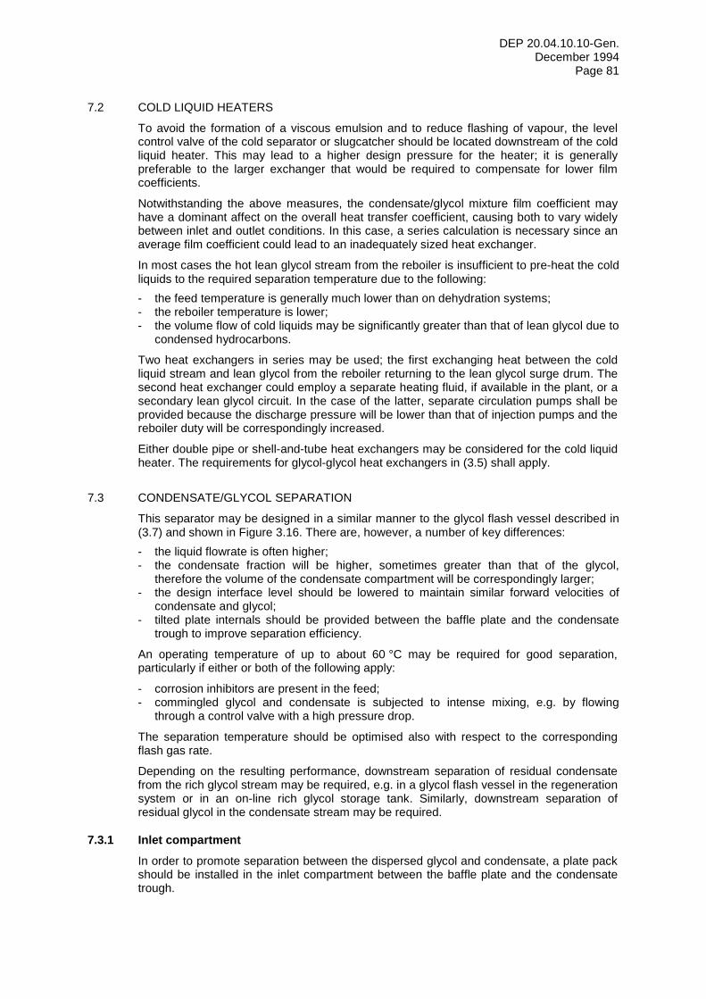
DEP 20.04.10.10-Gen. December 1994
Page 81
7.2 COLD LIQUID HEATERS
To avoid the formation of a viscous emulsion and to reduce flashing of vapour, the level control valve of the cold separator or slugcatcher should be located downstream of the cold liquid heater. This may lead to a higher design pressure for the heater; it is generally preferable to the larger exchanger that would be required to compensate for lower film coefficients.
Notwithstanding the above measures, the condensate/glycol mixture film coefficient may have a dominant affect on the overall heat transfer coefficient, causing both to vary widely between inlet and outlet conditions. In this case, a series calculation is necessary since an average film coefficient could lead to an inadequately sized heat exchanger.
In most cases the hot lean glycol stream from the reboiler is insufficient to pre-heat the cold liquids to the required separation temperature due to the following: - the feed temperature is generally much lower than on dehydration systems; - the reboiler temperature is lower; - the volume flow of cold liquids may be significantly greater than that of lean glycol due to
condensed hydrocarbons.
Two heat exchangers in series may be used; the first exchanging heat between the cold liquid stream and lean glycol from the reboiler returning to the lean glycol surge drum. The second heat exchanger could employ a separate heating fluid, if available in the plant, or a secondary lean glycol circuit. In the case of the latter, separate circulation pumps shall be provided because the discharge pressure will be lower than that of injection pumps and the reboiler duty will be correspondingly increased.
Either double pipe or shell-and-tube heat exchangers may be considered for the cold liquid heater. The requirements for glycol-glycol heat exchangers in (3.5) shall apply.
7.3 CONDENSATE/GLYCOL SEPARATION
This separator may be designed in a similar manner to the glycol flash vessel described in (3.7) and shown in Figure 3.16. There are, however, a number of key differences: - the liquid flowrate is often higher; - the condensate fraction will be higher, sometimes greater than that of the glycol,
therefore the volume of the condensate compartment will be correspondingly larger; - the design interface level should be lowered to maintain similar forward velocities of
condensate and glycol; - tilted plate internals should be provided between the baffle plate and the condensate
trough to improve separation efficiency.
An operating temperature of up to about 60 °C may be required for good separation, particularly if either or both of the following apply:
- corrosion inhibitors are present in the feed; - commingled glycol and condensate is subjected to intense mixing, e.g. by flowing
through a control valve with a high pressure drop.
The separation temperature should be optimised also with respect to the corresponding flash gas rate.
Depending on the resulting performance, downstream separation of residual condensate from the rich glycol stream may be required, e.g. in a glycol flash vessel in the regeneration system or in an on-line rich glycol storage tank. Similarly, downstream separation of residual glycol in the condensate stream may be required.
7.3.1 Inlet compartment In order to promote separation between the dispersed glycol and condensate, a plate pack should be installed in the inlet compartment between the baffle plate and the condensate trough.
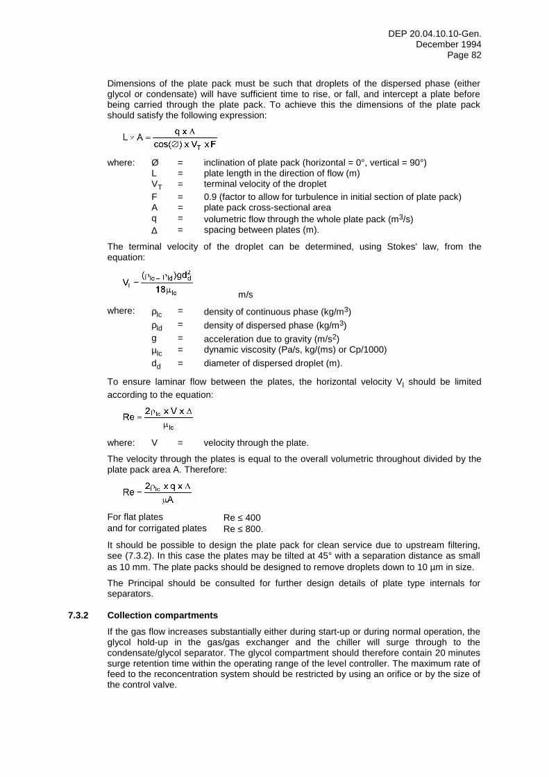
DEP 20.04.10.10-Gen. December 1994
Page 82
Dimensions of the plate pack must be such that droplets of the dispersed phase (either glycol or condensate) will have sufficient time to rise, or fall, and intercept a plate before being carried through the plate pack. To achieve this the dimensions of the plate pack should satisfy the following expression:
where: Ø = inclination of plate pack (horizontal = 0°, vertical = 90°) L = plate length in the direction of flow (m) VT = terminal velocity of the droplet F = 0.9 (factor to allow for turbulence in initial section of plate pack) A = plate pack cross-sectional area q = volumetric flow through the whole plate pack (m3/s) ∆ = spacing between plates (m).
The terminal velocity of the droplet can be determined, using Stokes' law, from the equation:
m/s
where: ρlc = density of continuous phase (kg/m3) ρld = density of dispersed phase (kg/m3) g = acceleration due to gravity (m/s2) µlc = dynamic viscosity (Pa/s, kg/(ms) or Cp/1000) dd = diameter of dispersed droplet (m).
To ensure laminar flow between the plates, the horizontal velocity Vl should be limited according to the equation:
where: V = velocity through the plate.
The velocity through the plates is equal to the overall volumetric throughout divided by the plate pack area A. Therefore:
For flat plates Re ≤ 400 and for corrigated plates Re ≤ 800.
It should be possible to design the plate pack for clean service due to upstream filtering, see (7.3.2). In this case the plates may be tilted at 45° with a separation distance as small as 10 mm. The plate packs should be designed to remove droplets down to 10 µm in size.
The Principal should be consulted for further design details of plate type internals for separators.
7.3.2 Collection compartments If the gas flow increases substantially either during start-up or during normal operation, the glycol hold-up in the gas/gas exchanger and the chiller will surge through to the condensate/glycol separator. The glycol compartment should therefore contain 20 minutes surge retention time within the operating range of the level controller. The maximum rate of feed to the reconcentration system should be restricted by using an orifice or by the size of the control valve.
DEP 20.04.10.10-Gen. December 1994
Page 83
The condensate collection compartment should provide a minimum 5 minutes condensate retention time in a 350 mm level change.
7.3.3 Cross-flow separator If the separator would have a diameter exceeding about 1.5 m, a cross-flow configuration as shown in Figure 7.1, should be considered. Forward velocities through the plate pack can then be limited by the vessel length as well as its diameter, which leads to a more compact and cheaper vessel.
The Principal should be consulted for a cross-flow design of condensate/glycol separator.
7.3.4 Hydrocyclones An alternative method for separation, but at a lower temperature, is the use of hydrocyclones. Experience with hydrocyclones in this service is limited, and the Principal should be consulted with regard to their possible use.
7.4 GLYCOL REGENERATION
The glycol regeneration system design shall be similar to that described for gas dehydration in (3.4), except as indicated herein.
7.4.1 Reboiler Maximum reboiler temperatures for hydrate inhibition are significantly less than for dehydration. For LTS processes lean concentrations are typically 75 percent to 85 percent (weight) and require reboiler temperatures of up to about 120 °C or 130 °C for MEG and DEG respectively, as shown in Figure 7.2. For wet gas pipelines, lean concentrations of 85 percent to 95 percent (weight) are typical and require reboiler temperatures up to about 145 °C or 155 °C; close to the degradation temperatures given in Table AI.1 in Appendix I.
Concentrations about 2 percent higher than indicated by Figure 7.2 may be achievable due to desorption of dissolved hydrocarbons.
7.4.2 Still column The differences in boiling points between water and MEG and DEG are not as great as with TEG. A greater number of stages and/or reflux are thus required to minimise vapour losses. For the regeneration of MEG, five theoretical trays are recommended. Since the reboiler and condenser are each one stage, three stages of packing are required.
To allow for upsets in gas flow through the gas/gas exchanger and the chiller, see (7.3.2), the still column should be designed for a surge of between 25 percent and 50 percent in excess of the design rate.
7.4.3 Reflux A reflux of approximately 50 percent for 80 percent concentration MEG is required to rectify vapours and minimise vapour losses. A vertical shell-and-tube heat exchanger is recommended for the reflux condenser with up to the full flow of rich glycol through the shell side.
7.5 PARTICLE FILTERS
Clean glycol is required to prevent clogging of the nozzles and a distorted spray pattern. The filters shall meet the requirements of (3.9.1). On commissioning, the lines between the filter and the nozzles require thorough flushing before installing the spray nozzles.
Two parallel full-flow 10 µm glycol filters shall also be provided on the discharge of the glycol pumps upstream of the injection spray nozzles.
DEP 20.04.10.10-Gen. December 1994
Page 84
Two parallel full-flow 15 µm glycol filters shall be provided in the glycol line downstream of the condensate/glycol separator.
For a wet gas pipeline, two additional full-flow glycol filters (50 µm) shall be provided in the liquid outlet line of the slugcatcher upstream of the heater(s). These filters remove solid impurities originating in the pipeline and slugcatcher before they can reach the heater(s), flow/level control valve and the condensate/glycol separator fitted with a plate pack.
7.6 GLYCOL PUMP FOR COLD LIQUID PRE-HEATER
If an external pre-heat source is required for the cold liquid heater and is not specified separately, an electric motor driven centrifugal pump shall be provided to circulate hot glycol from the bottom of the reboiler through a separate heat exchanger to achieve the desired inlet temperature to the glycol/condensate separator. The pump shall comply with DEP 31.29.02.30-Gen.
7.7 GLYCOL STORAGE
Sufficient rich and lean glycol storage capacity should be provided at the plant to meet the needs of the process, particularly with regard to availability. For a wet gas pipeline, additional lean glycol storage may be required at both the plant and production station in case of a failure of the return lean glycol pipeline.
Glycol storage tanks may be on or off-line. The choice is site-specific and should take into account the following factors: - thermal integration. On-line tanks will increase required heat input; - required injection temperature. Lean glycol from on-line storage will require pre-heating
before injection in an LTS plant; - possible use of an on-line rich glycol tank for final glycol/condensate separation; - pumping requirements.
Vertical fixed roof tanks should generally be used for onshore glycol storage and comply with DEP 34.51.01.31-Gen. and DEP 64.51.01.31-Gen. Tanks should have a nitrogen or dry gas blanket to exclude oxygen to reduce the risk of glycol degradation. The area around the storage tanks and installations shall be well ventilated, bunded and drained to the hazardous atmospheric drain system.
DEP 20.04.10.10-Gen. December 1994
Page 85
8 UPGRADING OF HYDRATE INHIBITION SYSTEMS An increase in the throughput or a reduction in the operating temperature of an LTS process or wet gas pipeline may demand upgrading of the glycol system. This could entail an increase in the required capacity and/or the lean glycol concentration. The following recommendations may allow simple upgrading of much of the glycol system hardware.
8.1 INLET SEPARATION
Upgrading might be avoided or reduced by lowering the temperature of the inlet separator upstream of the hydrate inhibitor injection point. This could be achieved by either installing or increasing the duty of an inlet cooler. Alternatively, it may be possible to partially expand the gas across a choke. The hydrate formation temperature will in all cases limit the amount of pre-cooling.
8.2 INJECTION SYSTEM
Experimenting with different nozzle arrangements may allow a reduction in the glycol injection rate, see (7.1). This will allow some spare capacity in heat exchangers, pumps and reboiler.
8.3 TYPE OF GLYCOL
MEG and DEG each have their advantages, see (6). Depending on existing bottlenecks in the glycol system and requirements of the upgrade, an overall advantage may be gained by changing the type of glycol used.
DEP 20.04.10.10-Gen. December 1994
Page 86
9 OPERATIONS AND MAINTENANCE OF HYDRATE INHIBITION SYSTEMS Operation and maintenance aspects of glycol regeneration equipment that form part of a hydrate inhibition system are covered generally in (5), except as supplemented herein.
9.1 GLYCOL SOLUTION PROBLEMS
Particular problems for glycol regeneration in hydrate inhibition systems are: - thermal decomposition; - salt accumulation.
9.1.1 Thermal decomposition Decomposition of contaminated MEG may occur at temperatures well below the decomposition temperature given in Table AI.1 of Appendix I. Reboiler temperatures should therefore be prevented from exceeding the level required to meet the lean glycol concentration, in Figure 7.2.
9.1.2 Salt accumulation Salt accumulation is more common in hydrate inhibition systems. If this is not preventable, either on-site or off-site desalination of the glycol will be necessary. In the latter case, the salt content should be controlled at a safe level just below the maximum allowable so as to minimise off-site batch processing quantities. See (5.1.5.4) and Appendix IV (1.4).
9.2 HYDRATE BLOCKAGE
Should there be incomplete atomisation of the glycol or inadequate distribution, hydrates will form in the process cooling equipment. Upstream of the heat exchangers large droplets of glycol may gravitate downward, impinging on the lower half of the tube sheet. There is then inadequate contact, allowing wet gas to pass through the upper bank of heat exchanger tubes. Hydrates form in these tubes, restricting the rate of flow and finally completely plugging the tubes. This results in higher gas velocities through the lower bank of tubes; however, these tubes are partially flooded with the glycol which has not been properly dispersed into the gas phase. The high velocity flow of gas may then cause the glycol to foam. This is mechanical rather than surfactant type foaming.
Similar results may occur when highly concentrated glycol is injected and there is insufficient dilution by absorption of water from the gas.
Inadequate hydrate inhibition may be caused by one or more of the following: - glycol too concentrated or too cold; - glycol injection rate being too low for the nozzles; - insufficient pressure drop across the nozzles; - nozzle configuration not giving complete cover of the flow cross-section; - relative position of nozzles being too distant or too close; - nozzles plugged or dirty.
Formation of hydrates in wet gas pipelines will restrict the gas flow and cause a pressure drop at the point of hydrate formation, and consequently a further temperature drop. The hydrates will eventually block the flow of gas in the pipeline. If the hydrates have not completely blocked the flow of gas, methanol can be injected into the gas and it will dissolve the hydrates over a period of time. Methanol injection will only be helpful if gas is still flowing in the line.
If the pipeline becomes completely plugged with hydrates, the quickest way to remove the hydrate block is to depressurise the pipeline (on both sides of the plug) and allow the hydrates to melt. Another method is to heat-trace the portion of the pipeline in which hydrates are located and thereby melt them. However, this is often not practical because the exact location of the blockage may not be known, or be at a point where heating is not possible, e.g. subsea.
DEP 20.04.10.10-Gen. December 1994
Page 87
Glycol operating conditions such as pressure, temperature, flow and concentration should be adjusted to comply with the nozzle manufacturer's performance data. It may also be necessary to experiment with different nozzle arrangements, see (7.1).
Methanol should be injected to remove hydrates formed during upset conditions.
9.3 GLYCOL LOSSES
Entrained glycol losses in condensate may be significant due to poor design or unfavourable operating conditions of the condensate/glycol separator. In a properly designed separator, inadequate pre-heating of the condensate/glycol feed is a potential cause for poor separation.
Dissolved glycol losses in condensate may be significant, such as 15 litres of MEG/m3 of condensate. Greater losses may be expected where the condensates are highly aromatic or sour. See (6) and Figure 6.5.
DEP 20.04.10.10-Gen. December 1994
Page 88
10 PROCESS CONTROL AND SAFEGUARDING Amended per Circular 42/96
All controls and instrumentation necessary for start-up, shut-down and normal operation shall be provided. All instruments, controls, control valves and shutdown valves shall be in accordance with the relevant DEPs, as follows (see 11):
Amended per Circular 16/99
Amended per Circular 15/04
DEP 32.10.03.10-Gen., DEP 32.31.00.32-Gen., DEP 32.31.00.34-Gen., DEP 32.31.50.10-Gen., DEP 32.31.50.11-Gen., DEP 32.31.50.13-Gen., DEP 32.37.10.11-Gen., DEP 32.37.20.10-Gen. and DEP 32.37.51.11-Gen.
Operation of the unit shall normally be from the control centre. In the cases where there is no control centre, a local panel be shall provided.
On-line equipment shall be provided to monitor the water content of the gas; see EP 89-2413. Hygroscopic types of dewpoint analysers may suffer interference, because:
- a low concentration of glycol in the treated gas has a negligible effect on accuracy but increases the response time. Larger concentrations cause drift in the output signal;
- the sensitivity to methanol is very high, particularly at low dewpoints.
Dewpoint analysers should not be located immediately downstream of the glycol contactor to avoid fouling by entrained glycol. On-line and off-line equipment is available for the direct measurement of water content.
The impact of the process variables on the glycol process is discussed in (2.9). The control philosophy presented here is based upon that description.
10.1 GLYCOL CONTACTOR
Wet process gas flows as an uncontrolled stream through the inlet gas separator to the glycol contactor. The pressure of the contactor is controlled by regulating the dry gas leaving the contactor. The flow of dry gas is metered upstream of this pressure control valve. The lean glycol to the contactor is cooled to a temperature slightly higher than the feed gas. The lean glycol is pumped to the absorber by positive displacement pumps. These pumps are normally sized for the maximum circulation rate, and would not generally need to be under flow control as the lean glycol quality is a more important control variable for the amount of dehydration. In the case where multiple contactors use one regenerator, flow control will be necessary to control the split, see Figure 10.1.
Rich glycol is used as reflux cooling medium for the glycol regenerator before entering the flash vessel. The preferred scheme for control of this should be based upon an integrated level control and exchanger bypass, illustrated in Figure 10.2.
With this scheme, the output of the level controller acts on both the reflux exchanger valve and its bypass simultaneously, reducing or increasing the flow to both. The temperature controller also acts simultaneously, opening one valve and closing the other. This scheme has a number of advantages over a separate level control valve and exchanger bypass valve. First, the range of control is increased and secondly the conditions at the bypass valve are always at the higher pressure, leading to more consistent performance because there is not a partially flashed glycol stream flowing through it. The scheme is only really practical, however, if implemented in a DCS. The level controller should then also be based upon Report WRC 859 which makes best use of the surge volume contained in the glycol absorber column.
There may be other considerations such as distance between absorber and regenerator, leading to a significantly larger amount of high pressure piping which would reduce the benefit of this scheme, in which case separate control valves in series may be used,
DEP 20.04.10.10-Gen. December 1994
Page 89
recognising that the valves at the regenerator will be in flashing service and should be sized accordingly.
10.2 FLASH VESSEL
On the glycol flash vessel, the pressure is controlled by a split range controller either releasing flash gas to the LP fuel gas system or admitting gas from a higher pressure source such as a high pressure fuel gas system. The level in the flash vessel is controlled by discharge of glycol to the regenerator. This controller should only be a simple proportional type.
10.3 REGENERATOR
The level in the regenerator reboiler is not positively controlled, but has a weir over which excess glycol flows into the surge drum, via the stripper if present. The level should, however, have a level alarm to warn of loss of level on interruption of the supply of rich glycol from the flash drum. The gas flow to the stripper, if fitted, should be a simple flow control.
The temperature in the reboiler is an important variable as indicated in 3.4.1. For efficient regeneration the glycol temperature should be held as high as possible whilst avoiding excursions which could lead to glycol degradation. There are a number of possiblities for the heating medium, the control of which is described as follows:
10.3.1 Fired heater Amended per Circular 57/03
The basic instrumentation and control should be engineered in accordance with DEP 31.24.00.30-Gen. The regenerator temperature controller should cascade onto a pressure or flow controller in the fuel gas supply.
10.3.2 Hot oil In this case, the hot oil flow to the reboiler is throttled by the action of the temperature controller onto a hot oil flow control cascade. Where the hot oil is subject to temperature disturbances, the temperature should be cascaded onto a heat flow controller as shown in Figure 10.3.
10.3.3 Electric heating No special requirements.
10.3.4 Steam heating Control of steam to a reboiler should be temperature cascaded through steam flow, since with condensing steam the flow is directly proportional to heat input.
If high pressure steam is used, then some pressure reduction and desuperheat may be required to guard against excessive surface temperatures with consequent thermal degradation of the glycol.
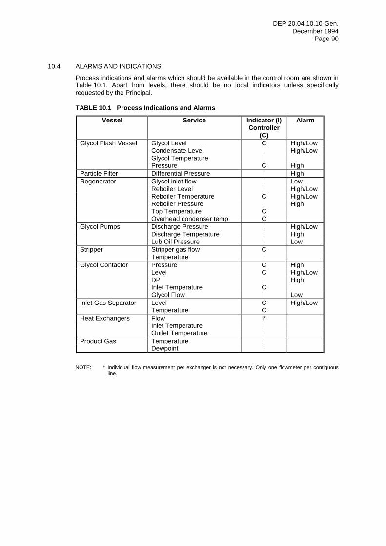
DEP 20.04.10.10-Gen. December 1994
Page 90
10.4 ALARMS AND INDICATIONS
Process indications and alarms which should be available in the control room are shown in Table 10.1. Apart from levels, there should be no local indicators unless specifically requested by the Principal.
TABLE 10.1 Process Indications and Alarms
Vessel Service Indicator (I) Controller
(C)
Alarm
Glycol Flash Vessel Glycol Level C High/Low Condensate Level I High/Low Glycol Temperature I Pressure C High Particle Filter Differential Pressure I High Regenerator Glycol inlet flow I Low Reboiler Level I High/Low Reboiler Temperature C High/Low Reboiler Pressure I High Top Temperature C Overhead condenser temp C Glycol Pumps Discharge Pressure I High/Low Discharge Temperature I High Lub Oil Pressure I Low Stripper Stripper gas flow C Temperature I Glycol Contactor Pressure C High Level C High/Low DP I High Inlet Temperature C Glycol Flow I Low Inlet Gas Separator Level C High/Low Temperature C Heat Exchangers Flow I* Inlet Temperature I Outlet Temperature I Product Gas Temperature I Dewpoint I
NOTE: * Individual flow measurement per exchanger is not necessary. Only one flowmeter per contiguous
line.
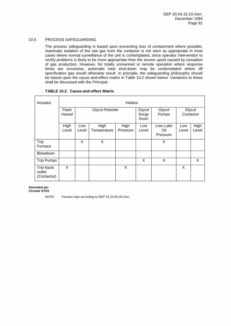
DEP 20.04.10.10-Gen. December 1994
Page 91
10.5 PROCESS SAFEGUARDING
The process safeguarding is based upon preventing loss of containment where possible. Automatic isolation of the raw gas from the contactor is not seen as appropriate in most cases where normal surveillance of the unit is contemplated, since operator intervention to rectify problems is likely to be more appropriate than the severe upset caused by cessation of gas production. However, for totally unmanned or remote operation where response times are excessive, automatic total shut-down may be contemplated where off specification gas would otherwise result. In principle, the safeguarding philosophy should be based upon the cause-and-effect matrix in Table 10.2 shown below. Variations to these shall be discussed with the Principal.
TABLE 10.2 Cause-and-effect Matrix
Actuator
Initiator
Flash Vessel
Glycol Reboiler Glycol Surge Drum
Glycol Pumps
Glycol Contactor
High Level
Low Level
High Temperature
High Pressure
Low Level
Low Lube Oil
Pressure
Low Level
High Level
Trip Furnace
X X X
Blowdown
Trip Pumps X X X
Trip liquid outlet (Contactor)
X X X
Amended per Circular 57/03
NOTE: Furnace trips according to DEP 31.24.00.30-Gen.
DEP 20.04.10.10-Gen. December 1994
Page 92
11 REFERENCES Amended per Circular 42/96
In this DEP reference is made to the following publications. NOTE: Unless specifically designated by date, the latest edition of each publication shall be used, together
with any amendments/supplements/revisions thereto.
SHELL STANDARDS Index to DEP publications and standard specifications
DEP 00.00.05.05-Gen.
Thermal insulation for hot services DEP 30.46.00.31-Gen. Painting and coating for new construction projects DEP 30.48.00.31-Gen. Trays for columns DEP 31.20.20.31-Gen. Shell-and-tube heat exchangers (Amendments/supplements to TEMA standards)
DEP 31.21.01.30-Gen.
Air cooled heat exchange equipment (Amendments/supplements to API 611)
DEP 31.21.70.31-Gen.
Gas/liquid separators - type selection and design rules
DEP 31.22.05.11-Gen.
Pressure vessels (Amendments/Supplements to BS 5500)
DEP 31.22.10.32-Gen.
Pressure vessels (Amendments/Supplements to ASME VIII)
DEP 31.22.20.31-Gen.
Amended per Circular 57/03
Fired heaters DEP 31.24.00.30-Gen. Pumps - selection, testing and installation DEP 31.29.02.11-Gen. Centrifugal pumps (Amendments/supplements to API Std 610)
DEP 31.29.02.30-Gen.
Reciprocating positive displacement pumps and metering pumps (Amendments/supplements to API 674 and API 675)
DEP 31.29.12.30-Gen.
Piping general requirements DEP 31.38.01.11-Gen. MF Piping classes DEP 31.38.01.12-Gen. EP Piping classes DEP 31.38.01.15-Gen. Shop and field fabrication of steel piping DEP 31.38.01.31-Gen.
Amended per Circular 16/99
Instrumentation symbols and identification on Process Engineering flow schemes
DEP 32.10.03.10-Gen.
DEP 20.04.10.10-Gen. December 1994
Page 93
Instruments for measurement and control DEP 32.31.00.32-Gen. Instrumentation documents and drawings DEP 32.31.00.34-Gen. On-line process stream analysis - Sample take-off and transportation
DEP 32.31.50.10-Gen.
On-line process stream analysis - Sample conditioning
DEP 32.31.50.11-Gen.
On-line process stream analysis - Analyser houses DEP 32.31.50.13-Gen.
Amended per Circular 45/01
Installation of on-line instruments DEP 32.37.10.11-Gen. Instrument signal lines DEP 32.37.20.10-Gen.
Amended per Circular 15/04
Instrument air lines DEP 32.37.51.11-Gen. Electrical engineering guidelines DEP 33.64.10.10-Gen. Standard vertical tanks - design and fabrication DEP 34.51.01.31-Gen. Standard vertical tanks - erection and testing DEP 64.51.01.31-Gen. SHELL STANDARD DRAWINGS Nameplate with bracket for vessel and heat exchange equipment
S 10.114
Cage ladder to columns, steel stacks and steel structures
S 28.011
Instrument name plates S 37.601 SHELL REPORTS
Amended per Circular 57/03
Design procedure and data for glycol contactors EP 92-1290 Gasunie cyclone separator design guidelines EP 93-1165 Technology to reduce waste emissions resulting from the use of glycol
EP 94-0930
EP Safety Manual, Hydrogen Sulphide (H2S) in Operations
EP 95-0317
EP Safety Manual, Fire control & Recovery EP 95-0351 Surge volume control algorithm, users manual WRC 859
April 1984
DEP 20.04.10.10-Gen. December 1994
Page 94
AMERICAN STANDARDS Glycol-type gas dehydration units. First edition, December 1990
API Spec 12GDU
Issued by: American Petroleum Institute 1220 L Street Northwest Washington DC 20005 USA.
Gas Processors Supplier's Association (GPSA) SI engineering data book
GPSA Engineering Data Book
Standard test method for chloride ion in water - Method B: silver nitrate titration
ASTM D 512
Standard test method for iron in water - Method A: photometric orthophenanthroline method
ASTM D 1068
Standard test method for pH of water ASTM D 1293 Standard test method for water in liquid petroleum products by Karl Fischer Reagent
ASTM D 1744
Standard test method for oil and grease and petroleum hydrocarbons in water.
ASTM D 3921
Issued by: American Society for Testing and Materials 1916 Race Street Philadelphia PA 19103 - 1187 USA.
BRITISH STANDARDS Institute of Petroleum Code of Practice Part 15: Area Classification Code for Petroleum Installations
Issued by: Institute of Petroleum 51 New Cavendish Street London W1M 8AR United Kingdom.
DEP 20.04.10.10-Gen. December 1994
Page 95
12 BIBLIOGRAPHY NOTE: The documents listed in this Bibliography are for information only and do not form an integral part of
this DEP.
Laboratory and field evaluations of water-in-gas measurement systems and determination of water content of natural gas
EP 89-2413
Recommendations on sampling and analysis of hydrocarbon fluids
EP 92-0980
Gas Conditioning Fact Book - Dow Chemical
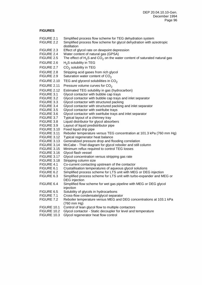
DEP 20.04.10.10-Gen. December 1994
Page 96
FIGURES FIGURE 2.1 Simplified process flow scheme for TEG dehydration system FIGURE 2.2 Simplified process flow scheme for glycol dehydration with azeotropic
distillation FIGURE 2.3 Effect of glycol rate on dewpoint depression FIGURE 2.4 Water content of natural gas (GPSA) FIGURE 2.5 The effect of H2S and CO2 on the water content of saturated natural gas FIGURE 2.6 H2S solubility in TEG FIGURE 2.7 CO2 solubility in TEG FIGURE 2.8 Stripping acid gases from rich glycol FIGURE 2.9 Saturation water content of CO2 FIGURE 2.10 TEG and glycerol solubilities in CO2 FIGURE 2.11 Pressure volume curves for CO2 FIGURE 2.12 Estimated TEG solubility in gas (hydrocarbon) FIGURE 3.1 Glycol contactor with bubble cap trays FIGURE 3.2 Glycol contactor with bubble cap trays and inlet separator FIGURE 3.3 Glycol contactor with structured packing FIGURE 3.4 Glycol contactor with structured packing and inlet separator FIGURE 3.5 Glycol contactor with swirltube trays FIGURE 3.6 Glycol contactor with swirltube trays and inlet separator FIGURE 3.7 Typical layout of a chimney tray FIGURE 3.8 Liquid distributor for glycol absorbers FIGURE 3.9 Layout of liquid predistributor pipe FIGURE 3.10 Fixed liquid drip pipe FIGURE 3.11 Reboiler temperature versus TEG concentration at 101.3 kPa (760 mm Hg) FIGURE 3.12 Typical regenerator heat balance FIGURE 3.13 Generalized pressure drop and flooding correlation FIGURE 3.14 McCabe - Thiel diagram for glycol reboiler and still column FIGURE 3.15 Minimum reflux required to control TEG losses FIGURE 3.16 Glycol flash vessel FIGURE 3.17 Glycol concentration versus stripping gas rate FIGURE 3.18 Stripping column size FIGURE 4.1 Co-current contacting upstream of the contactor FIGURE 6.1 Crystallisation temperatures of aqueous glycol solutions FIGURE 6.2 Simplified process scheme for LTS unit with MEG or DEG injection FIGURE 6.3 Simplified process scheme for LTS unit with turbo-expander and MEG or
DEG injection FIGURE 6.4 Simplified flow scheme for wet gas pipeline with MEG or DEG glycol
injection FIGURE 6.5 Solubility of glycols in hydrocarbons FIGURE 7.1 Cross-flow condensate/glycol separator FIGURE 7.2 Reboiler temperature versus MEG and DEG concentrations at 103.1 kPa
(760 mm Hg) FIGURE 10.1 Control of lean glycol flow to multiple contactors FIGURE 10.2 Glycol contactor - Static decoupler for level and temperature FIGURE 10.3 Glycol regenerator heat flow control
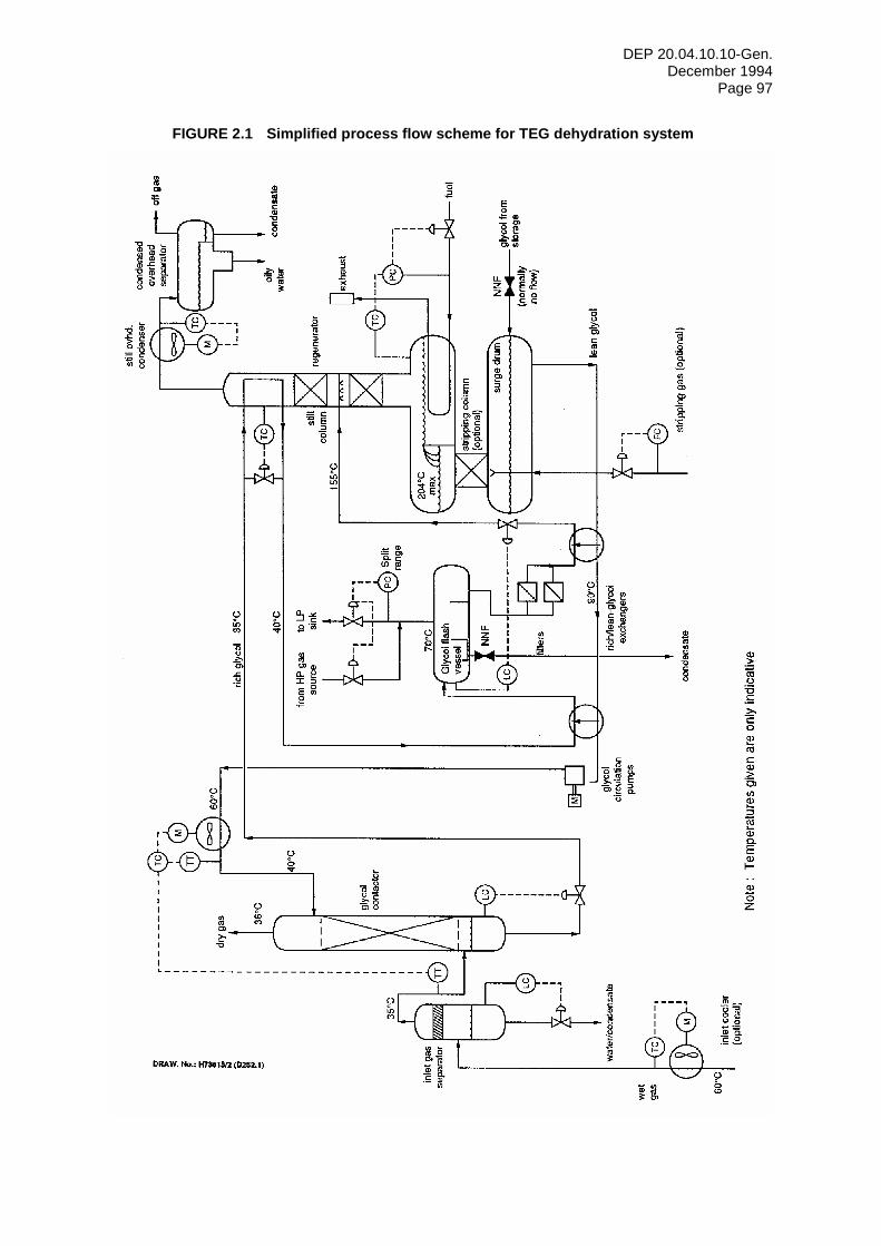
DEP 20.04.10.10-Gen. December 1994
Page 97
FIGURE 2.1 Simplified process flow scheme for TEG dehydration system
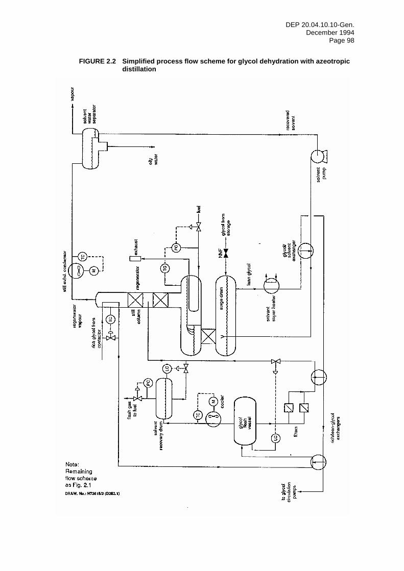
DEP 20.04.10.10-Gen. December 1994
Page 98
FIGURE 2.2 Simplified process flow scheme for glycol dehydration with azeotropic distillation
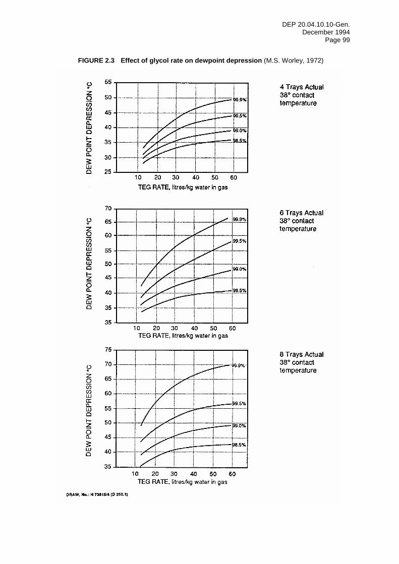
DEP 20.04.10.10-Gen. December 1994
Page 99
FIGURE 2.3 Effect of glycol rate on dewpoint depression (M.S. Worley, 1972)
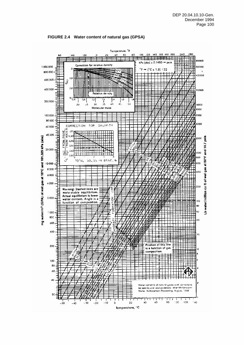
DEP 20.04.10.10-Gen. December 1994
Page 100
FIGURE 2.4 Water content of natural gas (GPSA)
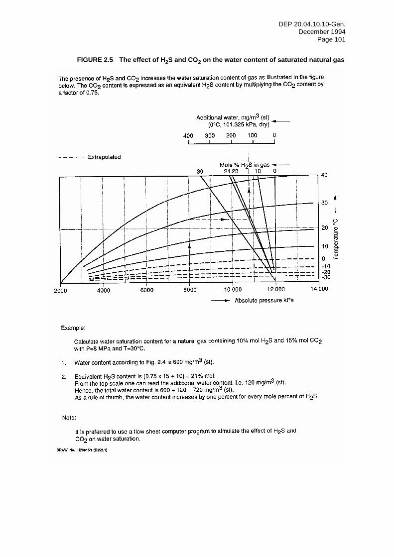
DEP 20.04.10.10-Gen. December 1994
Page 101
FIGURE 2.5 The effect of H2S and CO2 on the water content of saturated natural gas
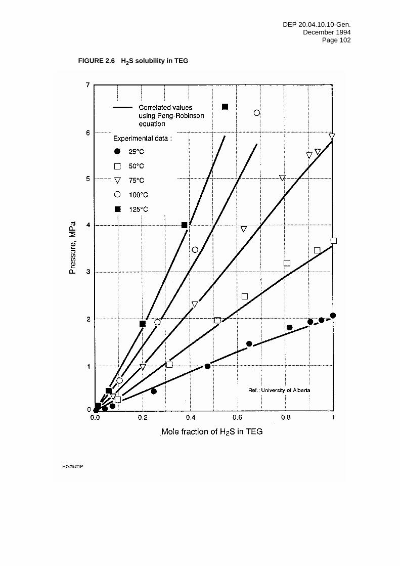
DEP 20.04.10.10-Gen. December 1994
Page 102
FIGURE 2.6 H2S solubility in TEG
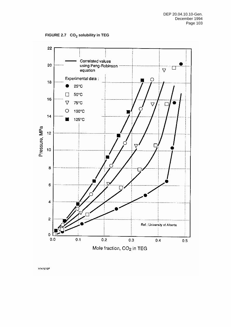
DEP 20.04.10.10-Gen. December 1994
Page 103
FIGURE 2.7 CO2 solubility in TEG
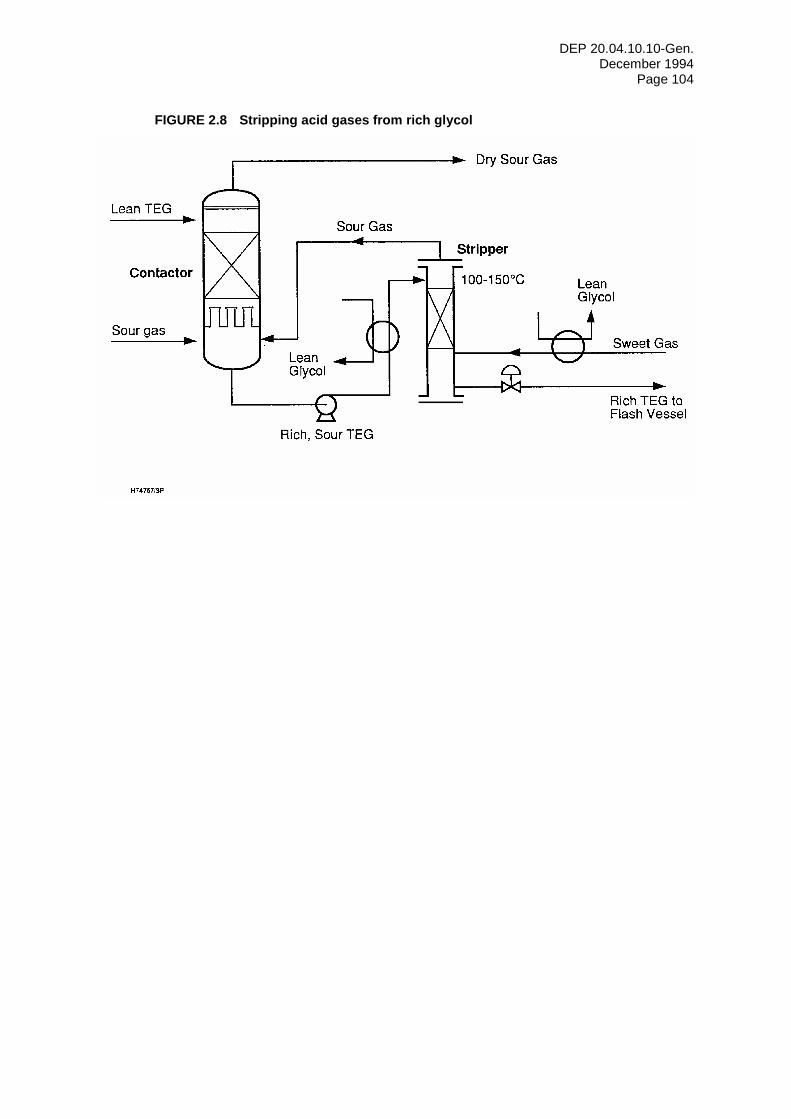
DEP 20.04.10.10-Gen. December 1994
Page 104
FIGURE 2.8 Stripping acid gases from rich glycol
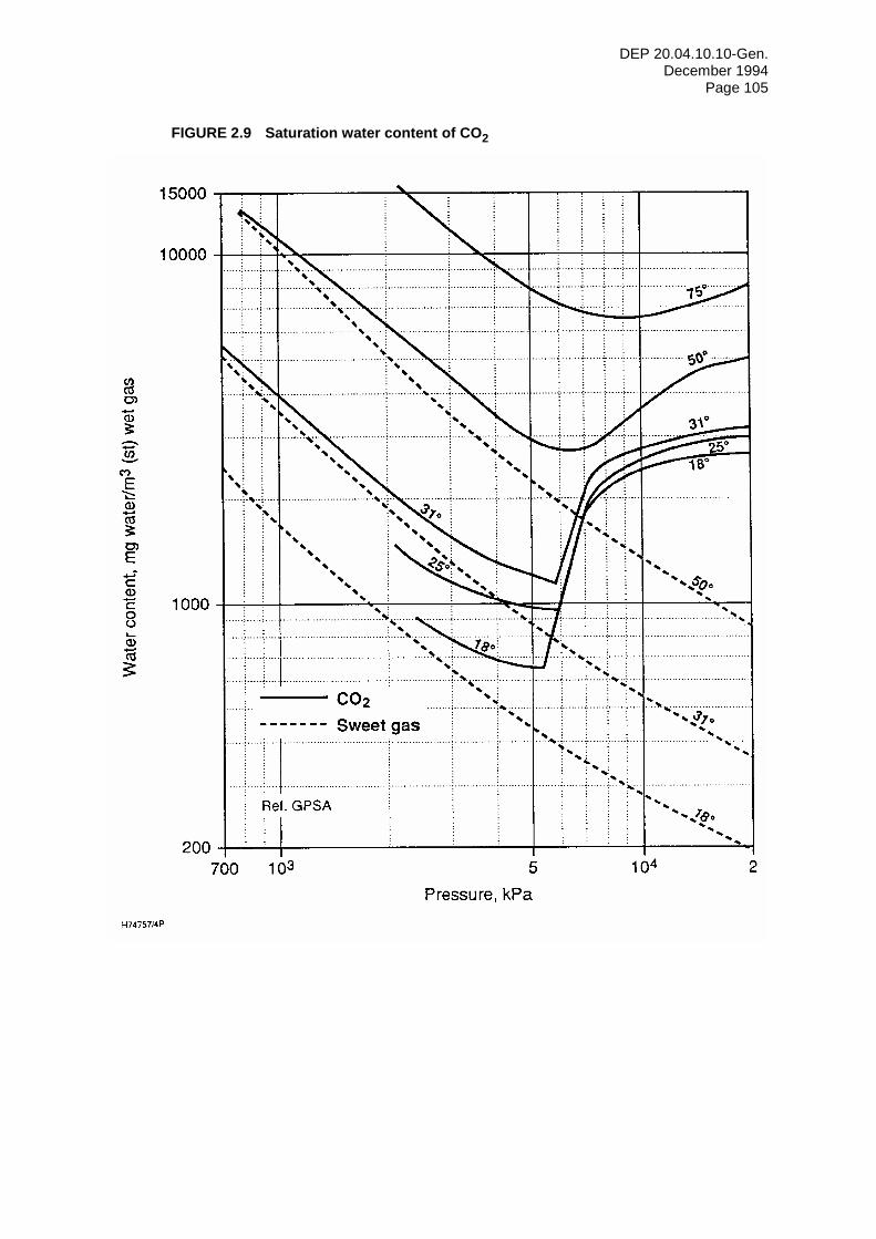
DEP 20.04.10.10-Gen. December 1994
Page 105
FIGURE 2.9 Saturation water content of CO2
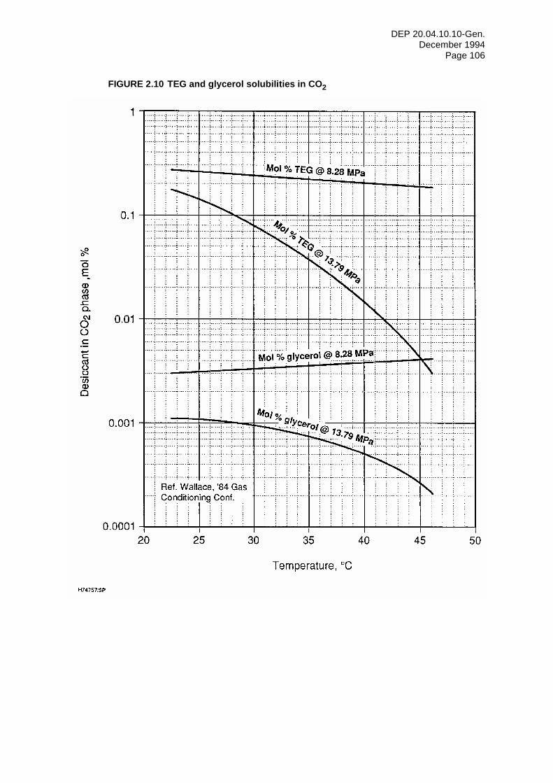
DEP 20.04.10.10-Gen. December 1994
Page 106
FIGURE 2.10 TEG and glycerol solubilities in CO2
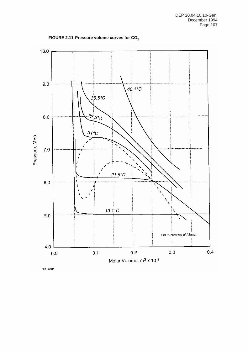
DEP 20.04.10.10-Gen. December 1994
Page 107
FIGURE 2.11 Pressure volume curves for CO2
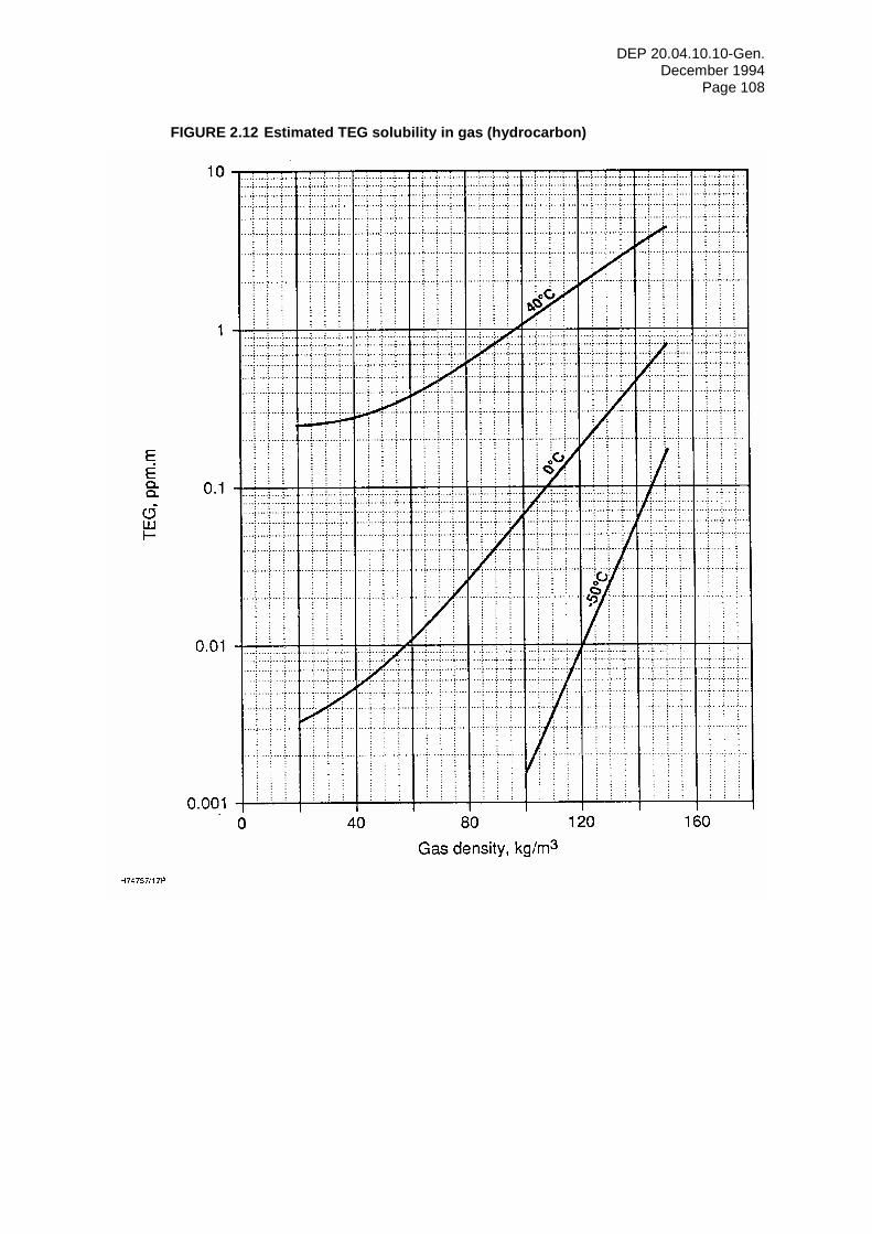
DEP 20.04.10.10-Gen. December 1994
Page 108
FIGURE 2.12 Estimated TEG solubility in gas (hydrocarbon)
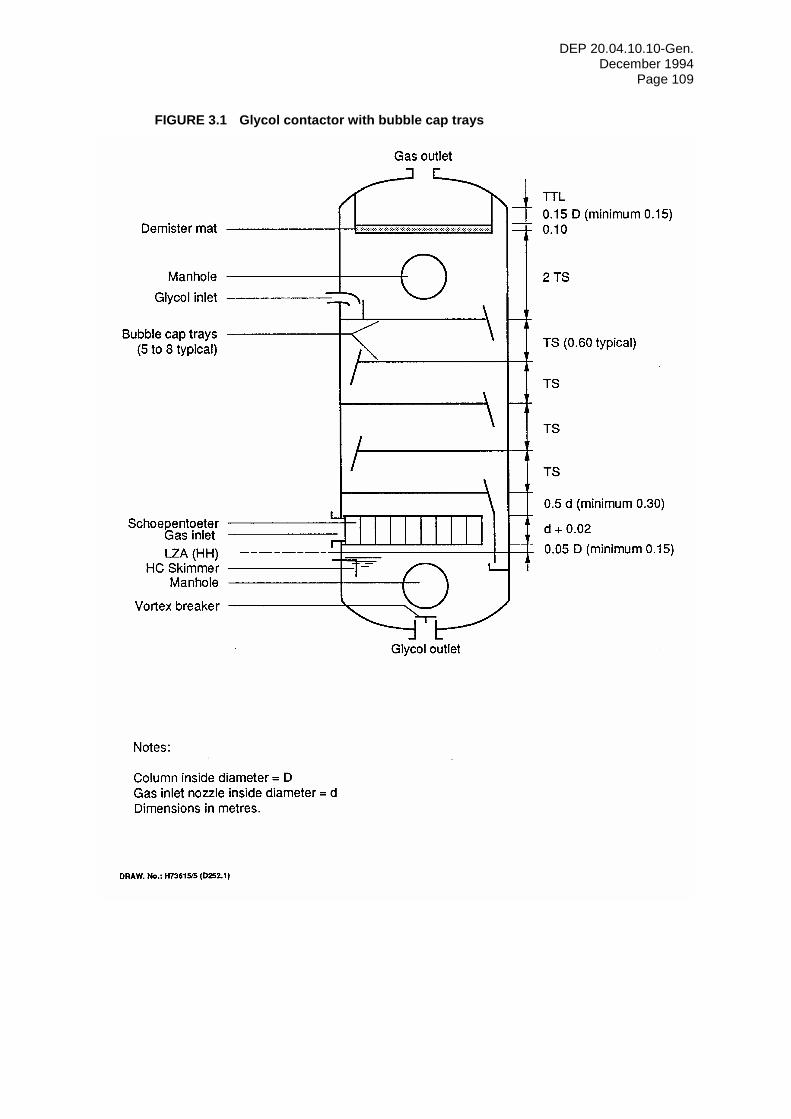
DEP 20.04.10.10-Gen. December 1994
Page 109
FIGURE 3.1 Glycol contactor with bubble cap trays
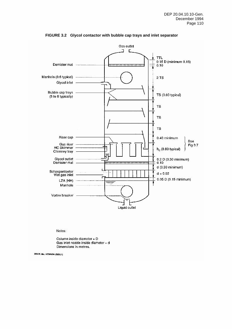
DEP 20.04.10.10-Gen. December 1994
Page 110
FIGURE 3.2 Glycol contactor with bubble cap trays and inlet separator
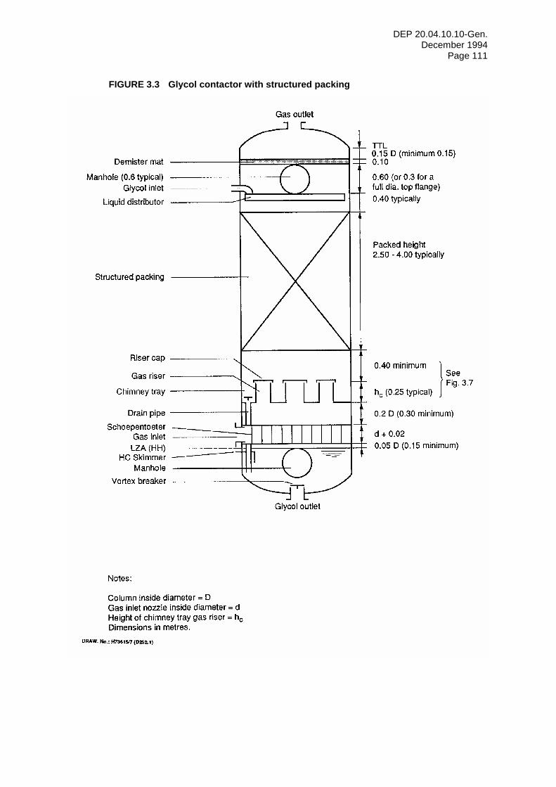
DEP 20.04.10.10-Gen. December 1994
Page 111
FIGURE 3.3 Glycol contactor with structured packing
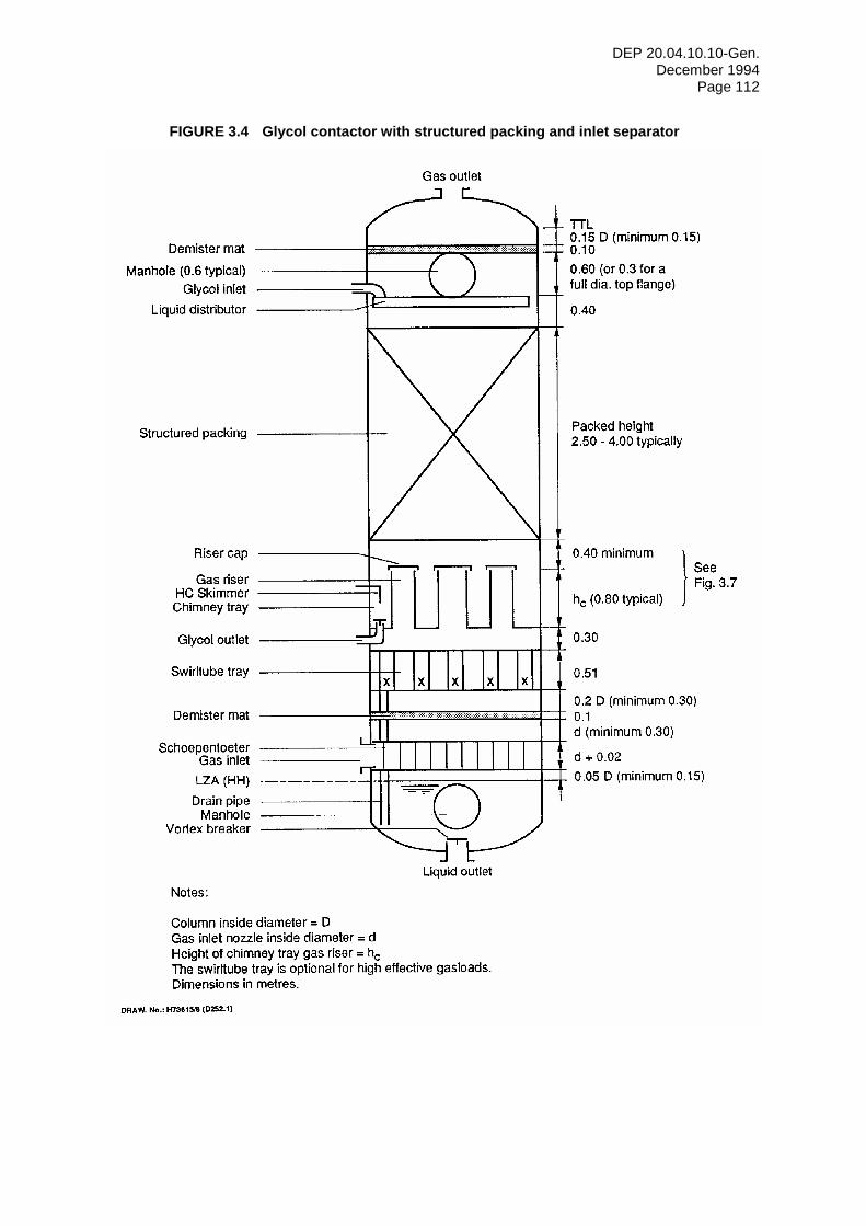
DEP 20.04.10.10-Gen. December 1994
Page 112
FIGURE 3.4 Glycol contactor with structured packing and inlet separator
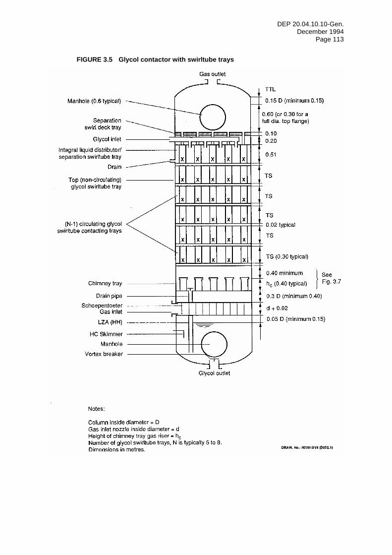
DEP 20.04.10.10-Gen. December 1994
Page 113
FIGURE 3.5 Glycol contactor with swirltube trays
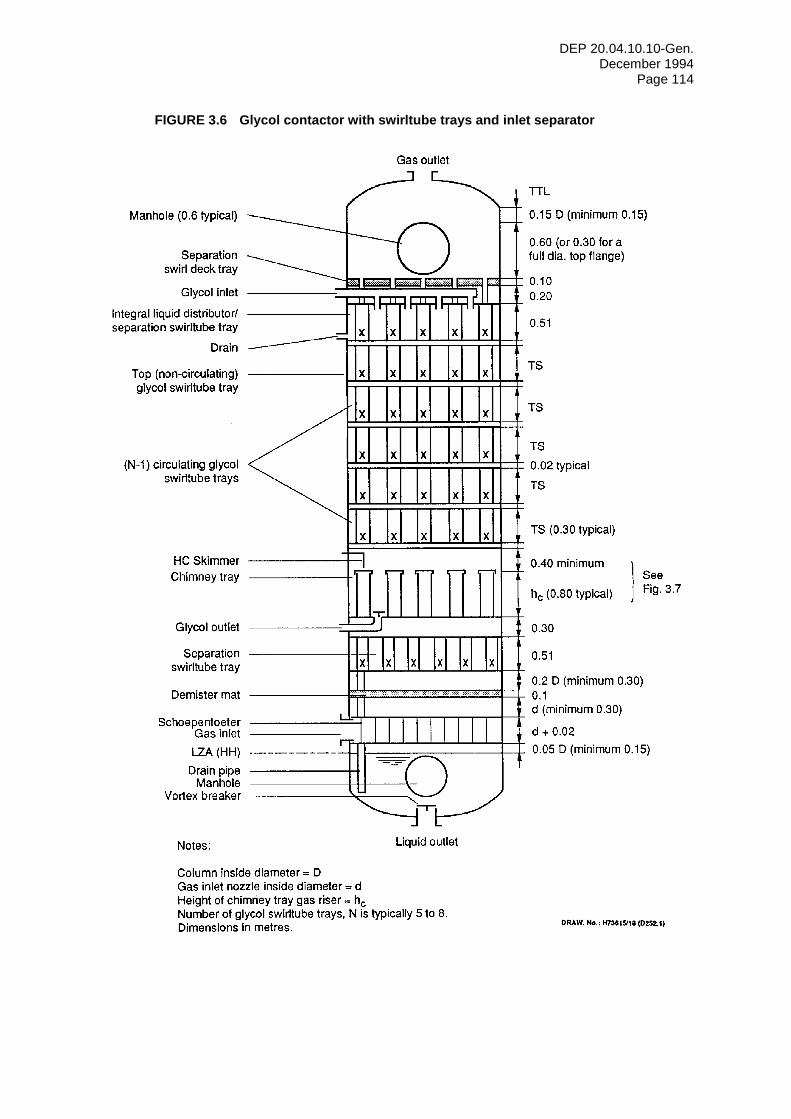
DEP 20.04.10.10-Gen. December 1994
Page 114
FIGURE 3.6 Glycol contactor with swirltube trays and inlet separator
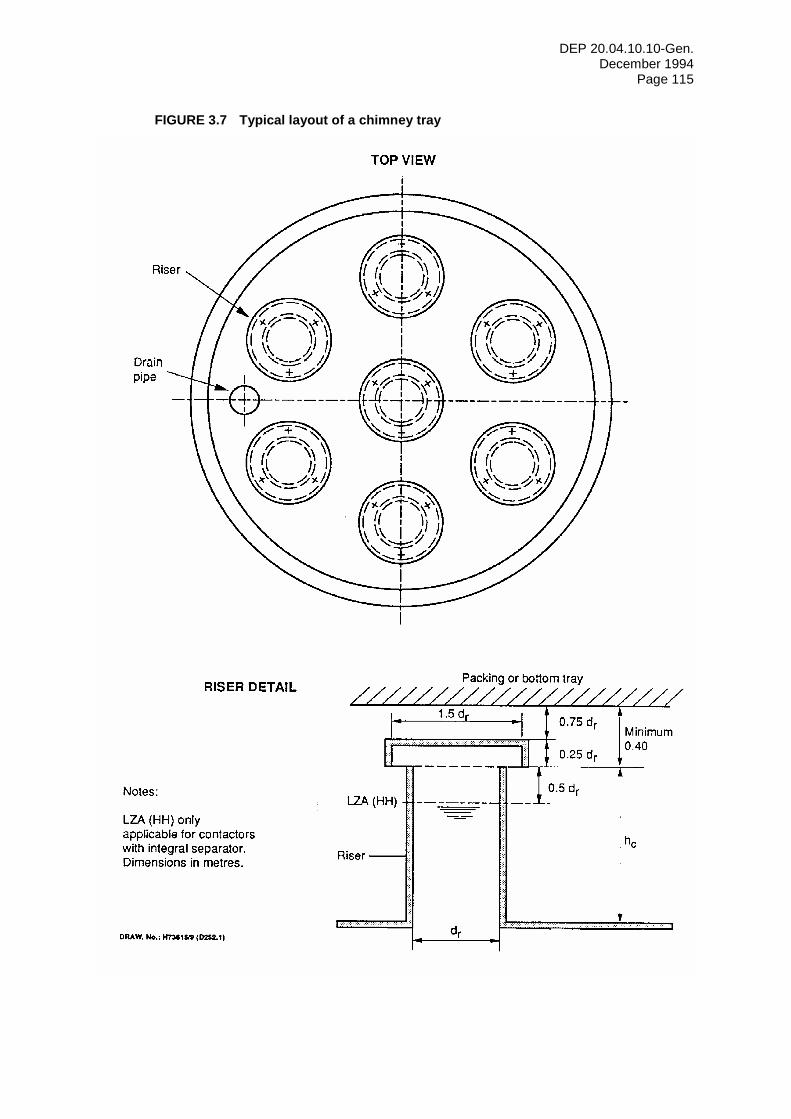
DEP 20.04.10.10-Gen. December 1994
Page 115
FIGURE 3.7 Typical layout of a chimney tray
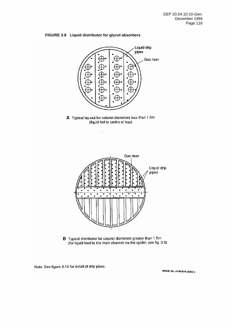
DEP 20.04.10.10-Gen. December 1994
Page 116
FIGURE 3.8 Liquid distributor for glycol absorbers
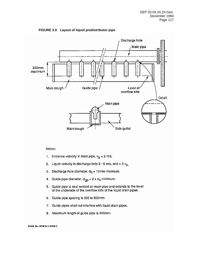
DEP 20.04.10.10-Gen. December 1994
Page 117
FIGURE 3.9 Layout of liquid predistributor pipe
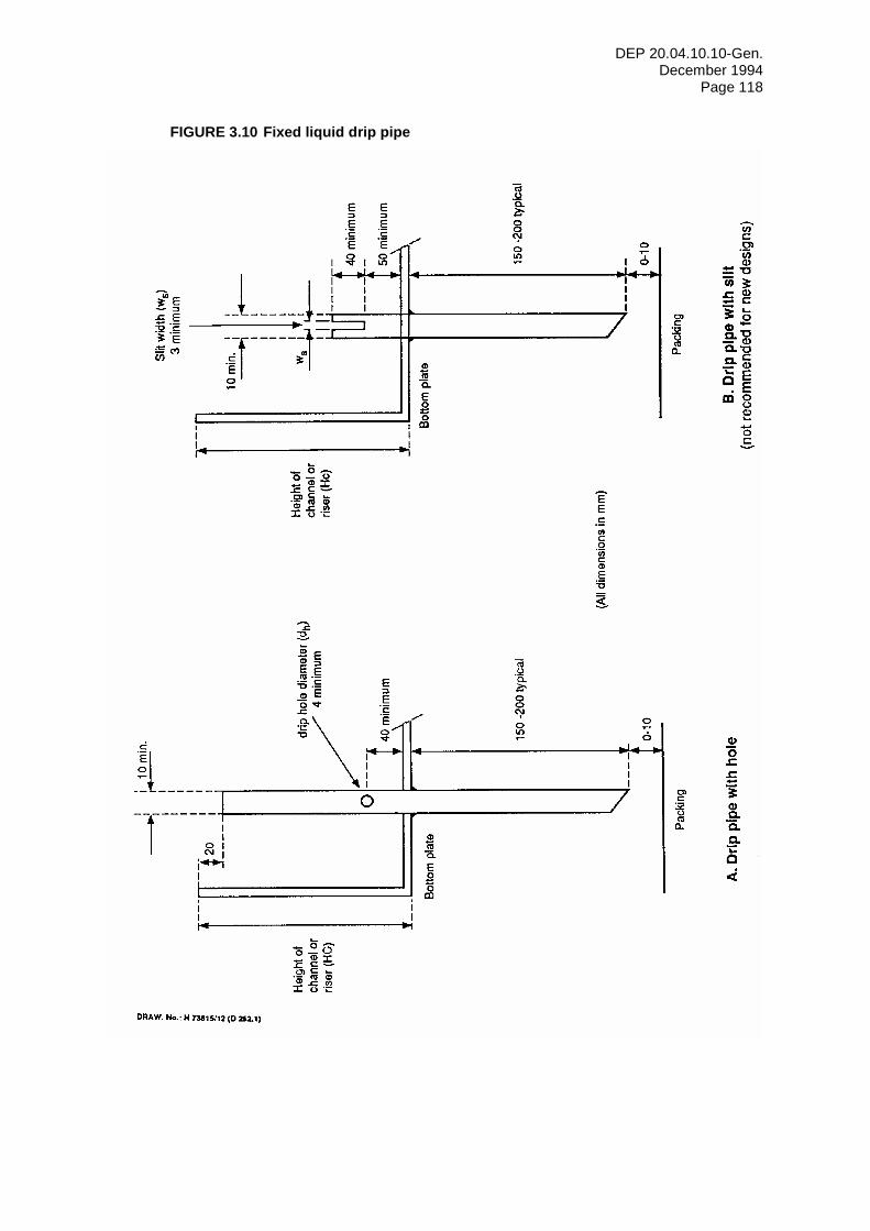
DEP 20.04.10.10-Gen. December 1994
Page 118
FIGURE 3.10 Fixed liquid drip pipe
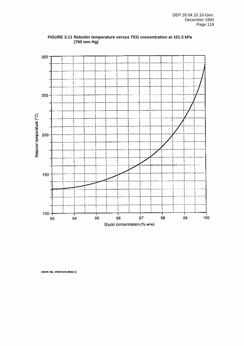
DEP 20.04.10.10-Gen. December 1994
Page 119
FIGURE 3.11 Reboiler temperature versus TEG concentration at 101.3 kPa (760 mm Hg)
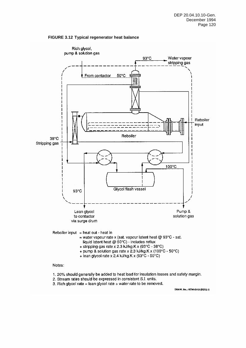
DEP 20.04.10.10-Gen. December 1994
Page 120
FIGURE 3.12 Typical regenerator heat balance
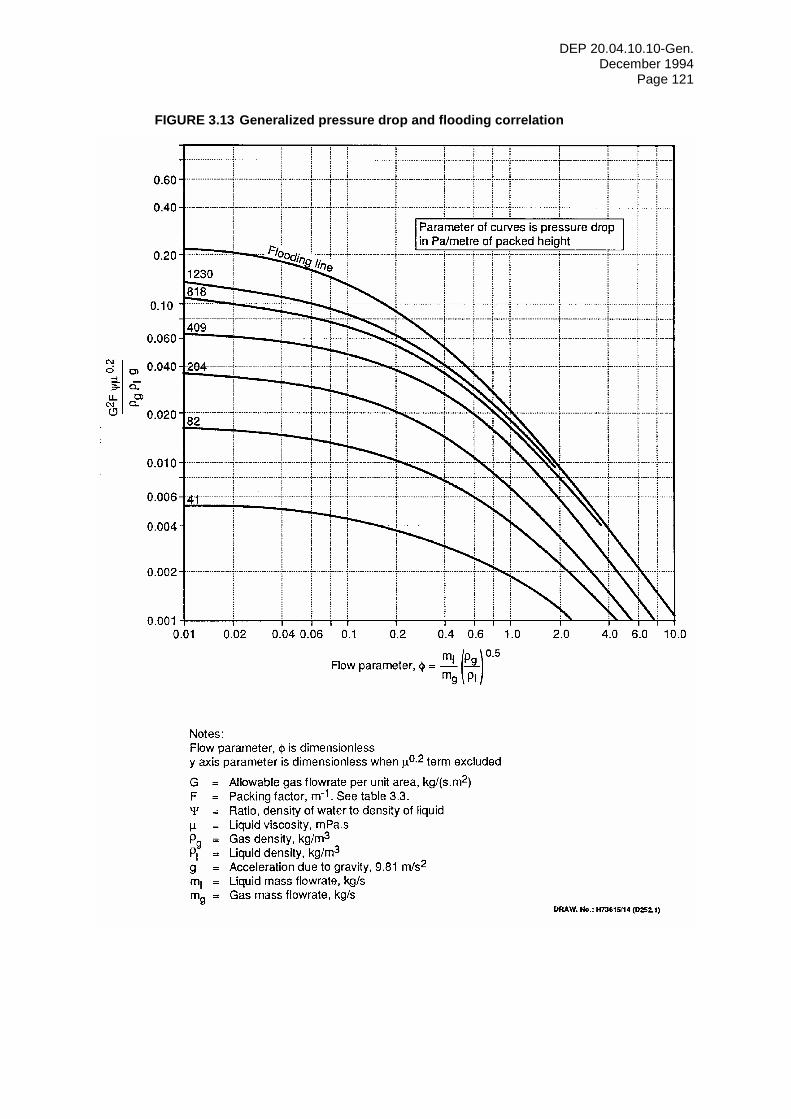
DEP 20.04.10.10-Gen. December 1994
Page 121
FIGURE 3.13 Generalized pressure drop and flooding correlation
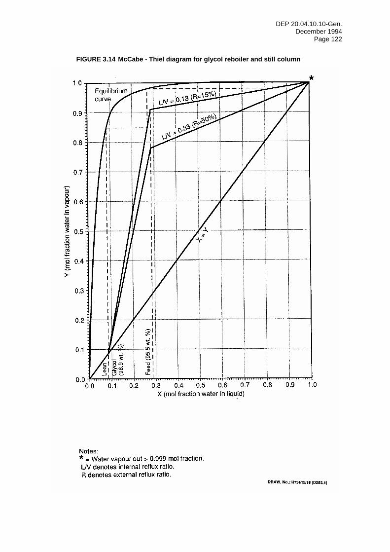
DEP 20.04.10.10-Gen. December 1994
Page 122
FIGURE 3.14 McCabe - Thiel diagram for glycol reboiler and still column
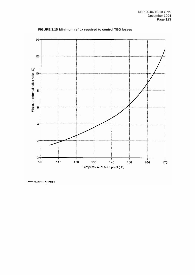
DEP 20.04.10.10-Gen. December 1994
Page 123
FIGURE 3.15 Minimum reflux required to control TEG losses
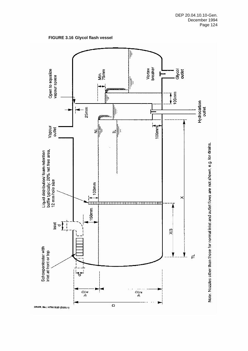
DEP 20.04.10.10-Gen. December 1994
Page 124
FIGURE 3.16 Glycol flash vessel
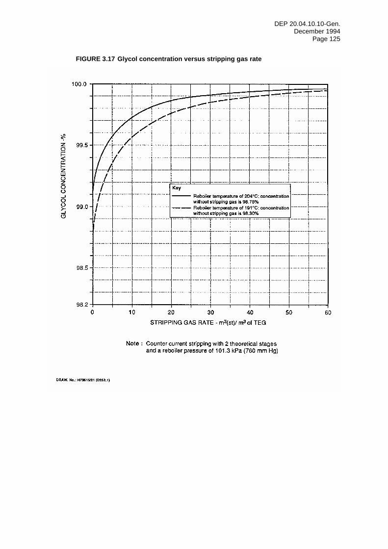
DEP 20.04.10.10-Gen. December 1994
Page 125
FIGURE 3.17 Glycol concentration versus stripping gas rate
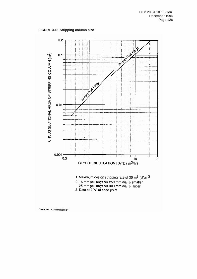
DEP 20.04.10.10-Gen. December 1994
Page 126
FIGURE 3.18 Stripping column size
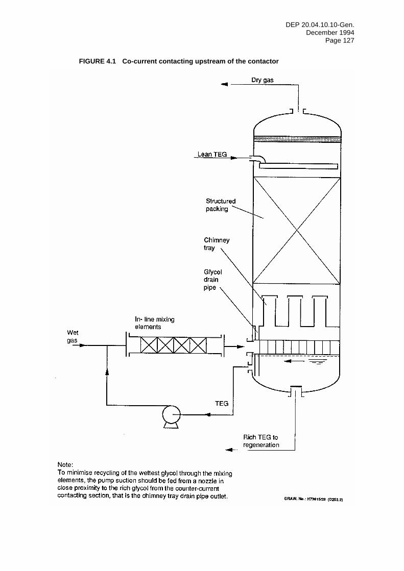
DEP 20.04.10.10-Gen. December 1994
Page 127
FIGURE 4.1 Co-current contacting upstream of the contactor
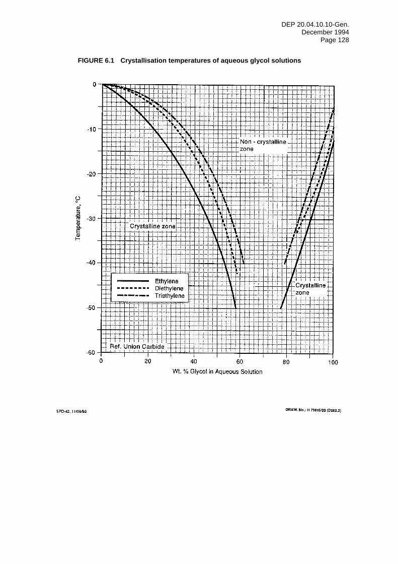
DEP 20.04.10.10-Gen. December 1994
Page 128
FIGURE 6.1 Crystallisation temperatures of aqueous glycol solutions
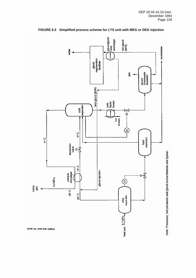
DEP 20.04.10.10-Gen. December 1994
Page 129
FIGURE 6.2 Simplified process scheme for LTS unit with MEG or DEG injection
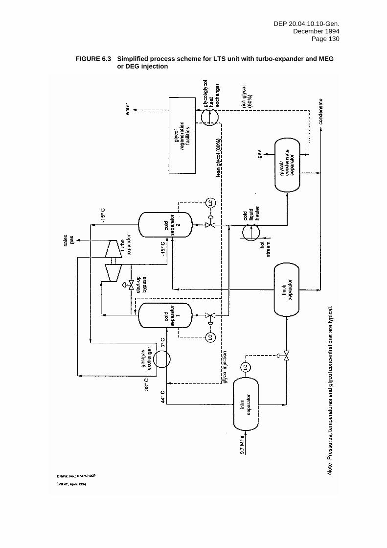
DEP 20.04.10.10-Gen. December 1994
Page 130
FIGURE 6.3 Simplified process scheme for LTS unit with turbo-expander and MEG or DEG injection
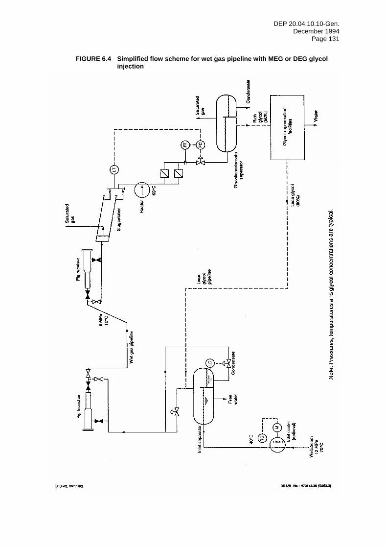
DEP 20.04.10.10-Gen. December 1994
Page 131
FIGURE 6.4 Simplified flow scheme for wet gas pipeline with MEG or DEG glycol injection
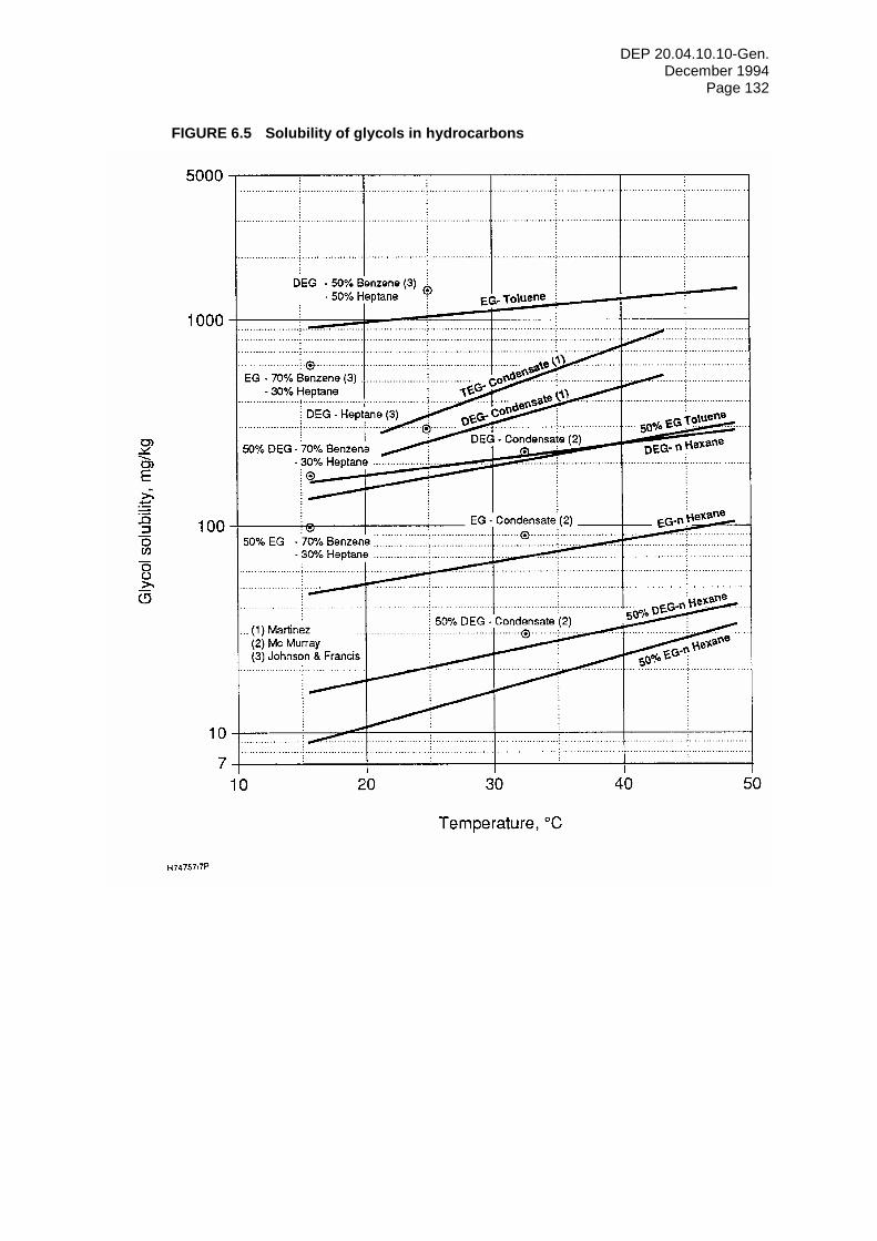
DEP 20.04.10.10-Gen. December 1994
Page 132
FIGURE 6.5 Solubility of glycols in hydrocarbons
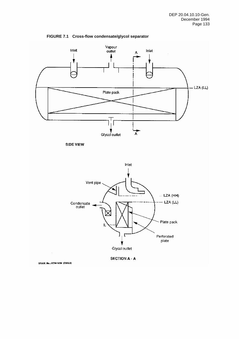
DEP 20.04.10.10-Gen. December 1994
Page 133
FIGURE 7.1 Cross-flow condensate/glycol separator
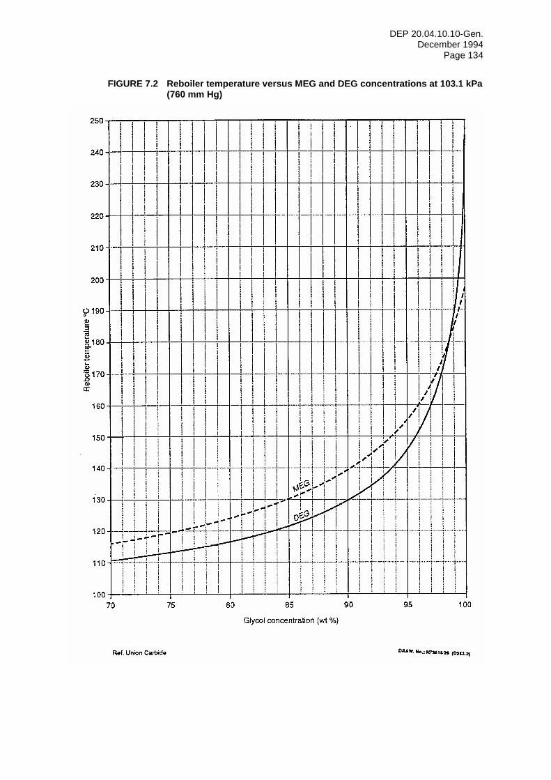
DEP 20.04.10.10-Gen. December 1994
Page 134
FIGURE 7.2 Reboiler temperature versus MEG and DEG concentrations at 103.1 kPa (760 mm Hg)
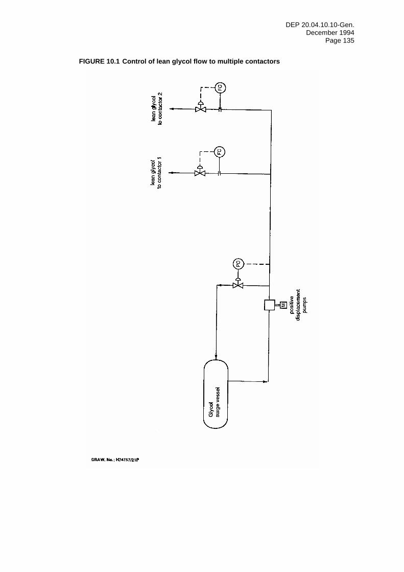
DEP 20.04.10.10-Gen. December 1994
Page 135
FIGURE 10.1 Control of lean glycol flow to multiple contactors
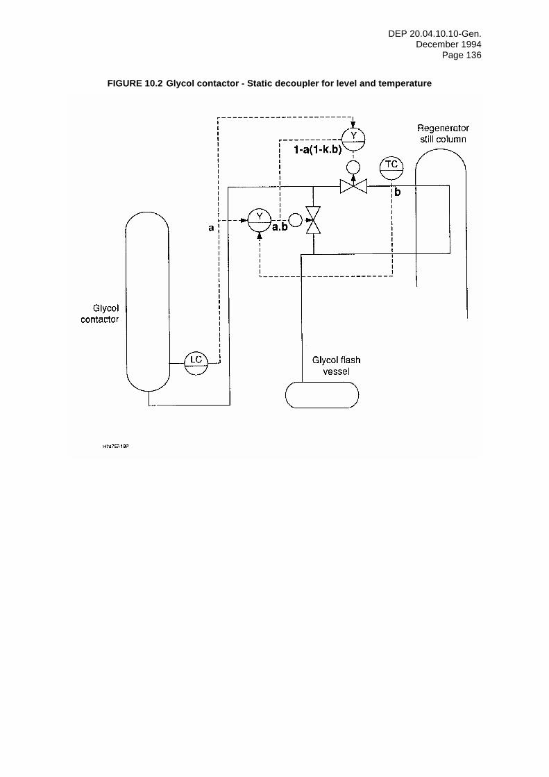
DEP 20.04.10.10-Gen. December 1994
Page 136
FIGURE 10.2 Glycol contactor - Static decoupler for level and temperature
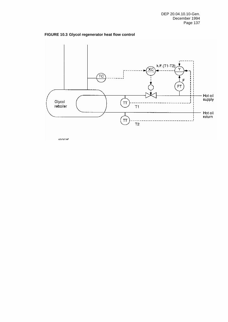
DEP 20.04.10.10-Gen. December 1994
Page 137
FIGURE 10.3 Glycol regenerator heat flow control
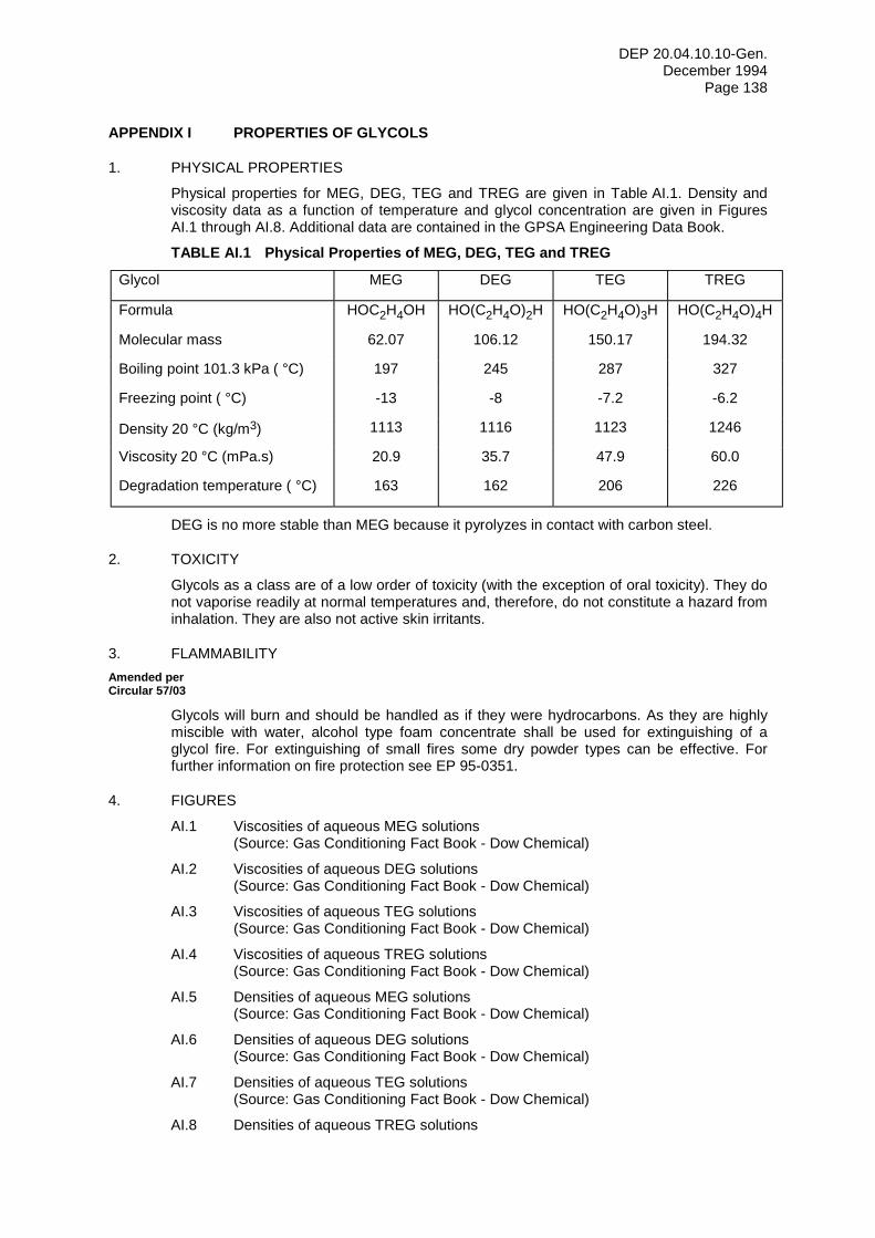
DEP 20.04.10.10-Gen. December 1994
Page 138
APPENDIX I PROPERTIES OF GLYCOLS
1. PHYSICAL PROPERTIES
Physical properties for MEG, DEG, TEG and TREG are given in Table AI.1. Density and viscosity data as a function of temperature and glycol concentration are given in Figures AI.1 through AI.8. Additional data are contained in the GPSA Engineering Data Book.
TABLE AI.1 Physical Properties of MEG, DEG, TEG and TREG
Glycol MEG DEG TEG TREG
Formula HOC2H4OH HO(C2H4O)2H HO(C2H4O)3H HO(C2H4O)4H
Molecular mass 62.07 106.12 150.17 194.32
Boiling point 101.3 kPa ( °C) 197 245 287 327
Freezing point ( °C) -13 -8 -7.2 -6.2
Density 20 °C (kg/m3) 1113 1116 1123 1246
Viscosity 20 °C (mPa.s) 20.9 35.7 47.9 60.0
Degradation temperature ( °C) 163 162 206 226
DEG is no more stable than MEG because it pyrolyzes in contact with carbon steel.
2. TOXICITY
Glycols as a class are of a low order of toxicity (with the exception of oral toxicity). They do not vaporise readily at normal temperatures and, therefore, do not constitute a hazard from inhalation. They are also not active skin irritants.
3. FLAMMABILITY Amended per Circular 57/03
Glycols will burn and should be handled as if they were hydrocarbons. As they are highly miscible with water, alcohol type foam concentrate shall be used for extinguishing of a glycol fire. For extinguishing of small fires some dry powder types can be effective. For further information on fire protection see EP 95-0351.
4. FIGURES
AI.1 Viscosities of aqueous MEG solutions (Source: Gas Conditioning Fact Book - Dow Chemical)
AI.2 Viscosities of aqueous DEG solutions (Source: Gas Conditioning Fact Book - Dow Chemical)
AI.3 Viscosities of aqueous TEG solutions (Source: Gas Conditioning Fact Book - Dow Chemical)
AI.4 Viscosities of aqueous TREG solutions (Source: Gas Conditioning Fact Book - Dow Chemical)
AI.5 Densities of aqueous MEG solutions (Source: Gas Conditioning Fact Book - Dow Chemical)
AI.6 Densities of aqueous DEG solutions (Source: Gas Conditioning Fact Book - Dow Chemical)
AI.7 Densities of aqueous TEG solutions (Source: Gas Conditioning Fact Book - Dow Chemical)
AI.8 Densities of aqueous TREG solutions

DEP 20.04.10.10-Gen. December 1994
Page 139
(Source: Gas Conditioning Fact Book - Dow Chemical)
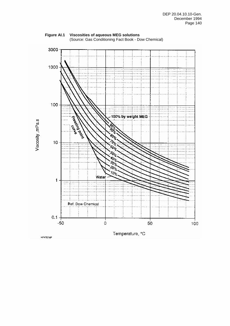
DEP 20.04.10.10-Gen. December 1994
Page 140
Figure AI.1 Viscosities of aqueous MEG solutions (Source: Gas Conditioning Fact Book - Dow Chemical)
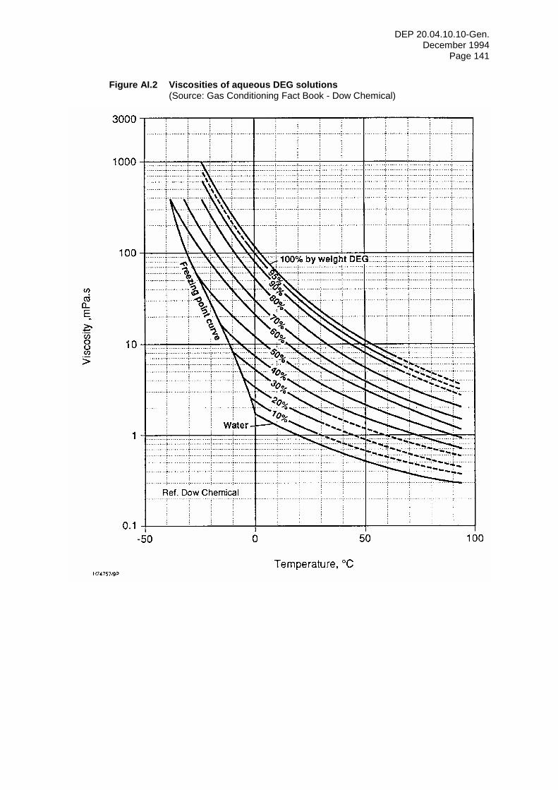
DEP 20.04.10.10-Gen. December 1994
Page 141
Figure AI.2 Viscosities of aqueous DEG solutions (Source: Gas Conditioning Fact Book - Dow Chemical)
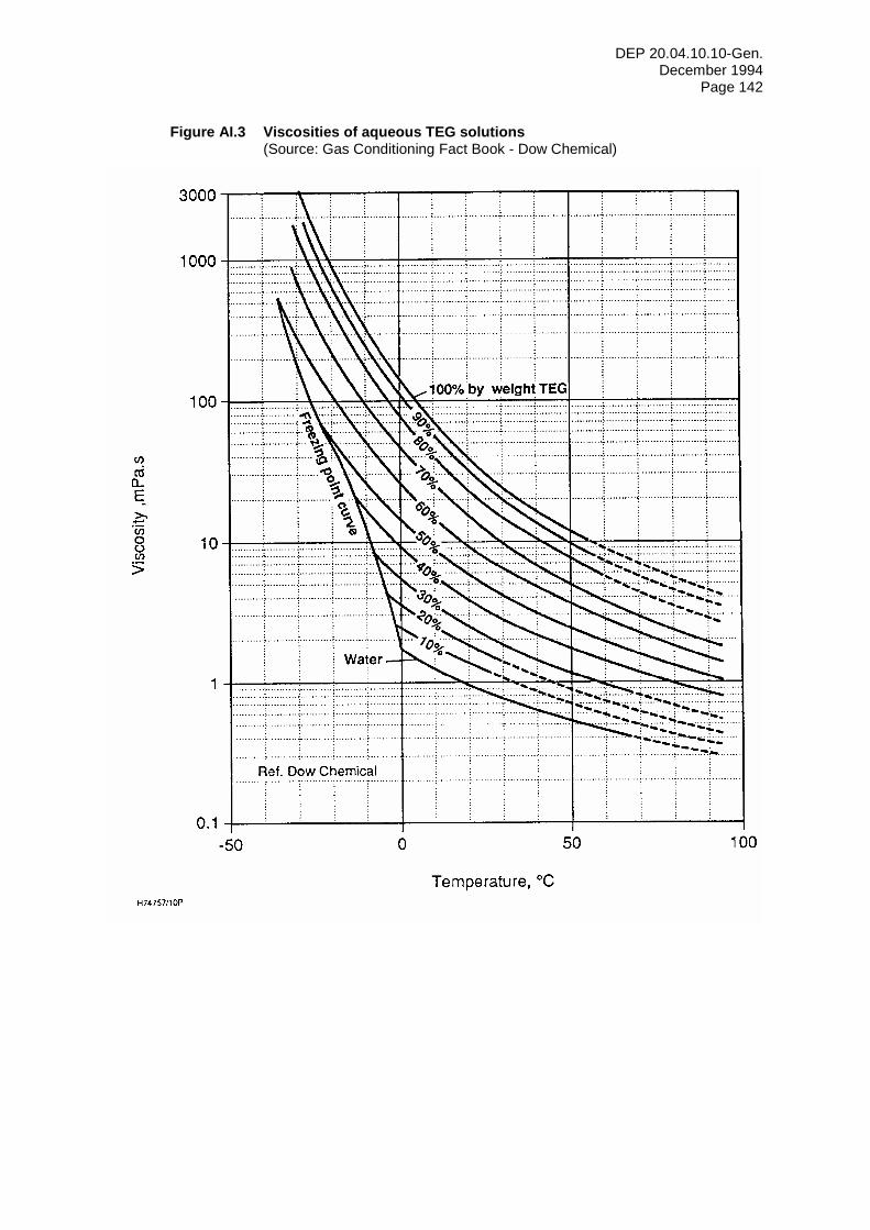
DEP 20.04.10.10-Gen. December 1994
Page 142
Figure AI.3 Viscosities of aqueous TEG solutions (Source: Gas Conditioning Fact Book - Dow Chemical)
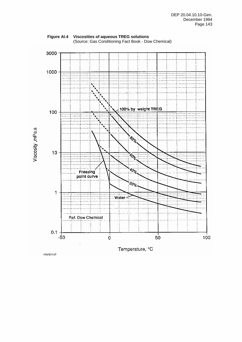
DEP 20.04.10.10-Gen. December 1994
Page 143
Figure AI.4 Viscosities of aqueous TREG solutions (Source: Gas Conditioning Fact Book - Dow Chemical)
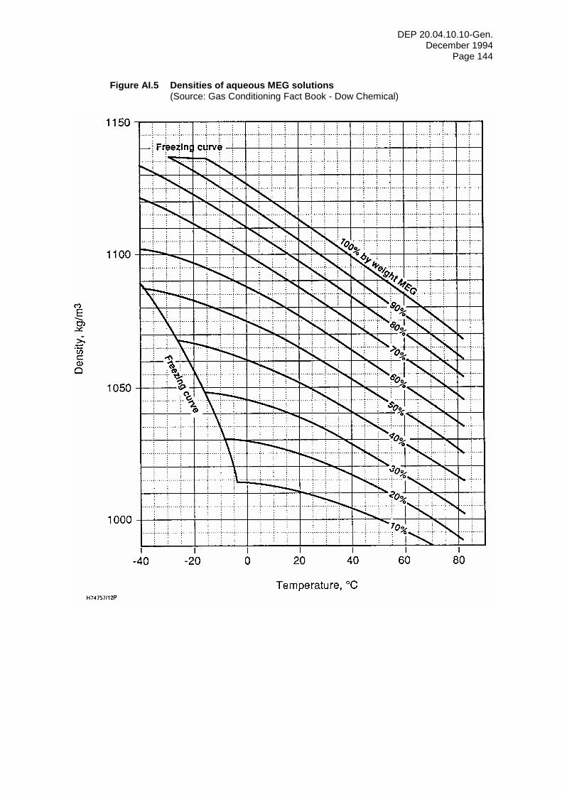
DEP 20.04.10.10-Gen. December 1994
Page 144
Figure AI.5 Densities of aqueous MEG solutions (Source: Gas Conditioning Fact Book - Dow Chemical)
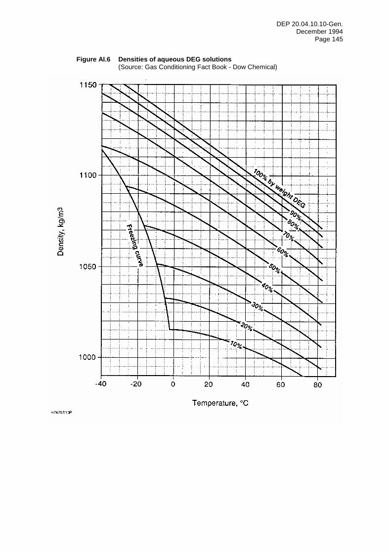
DEP 20.04.10.10-Gen. December 1994
Page 145
Figure AI.6 Densities of aqueous DEG solutions (Source: Gas Conditioning Fact Book - Dow Chemical)
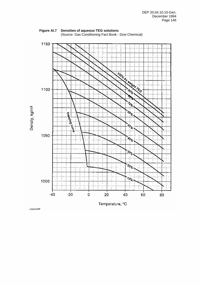
DEP 20.04.10.10-Gen. December 1994
Page 146
Figure AI.7 Densities of aqueous TEG solutions (Source: Gas Conditioning Fact Book - Dow Chemical)
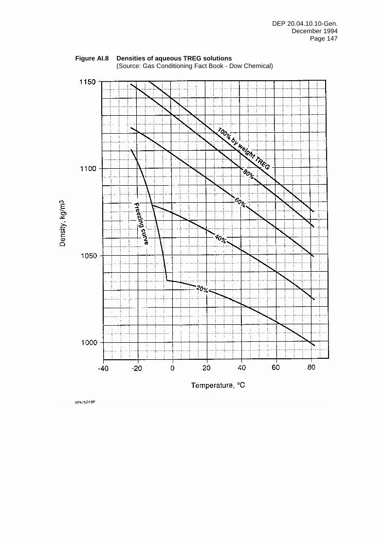
DEP 20.04.10.10-Gen. December 1994
Page 147
Figure AI.8 Densities of aqueous TREG solutions (Source: Gas Conditioning Fact Book - Dow Chemical)
DEP 20.04.10.10-Gen. December 1994
Page 148
APPENDIX II GLYCOL FOAM CONTROL TEST 1. Principle: Air is bubbled through the glycol sample at a definitive rate for 5 minutes
and the foam height and stability are measured. This test is not definitive, it is intended to demonstrate the effectiveness of different anti-foaming agents (AF) in suppressing foaming.
2. Apparatus See Figure AII.1.
3. Pour a 200 ml of sample into a 1000 ml cylinder. Connect the air delivery tube and introduce oil-free air at 4 litres/min. Allow the bubbling to continue for five minutes, stop the air flow and simultaneously start a stopwatch and measure the height of the foam. Record the time for the foam to break completely. NOTE: Foam height in ml is the difference between height of the foam and the initial height of the liquid.
This procedure can be used to determine the best AF and required dosage to control foaming in glycol contactors. Care should be exercised in cleaning the equipment since very small amounts of AF may affect the test.
Do not add AFs to the system without experimenting with them in the test apparatus. Do not mix AFs when running foam tests. If one AF does not do the required job, start with another glycol sample to run the foam test with the new AF. The samples for the foaming test should ideally be taken from the system at the point where most of the foaming occurs.
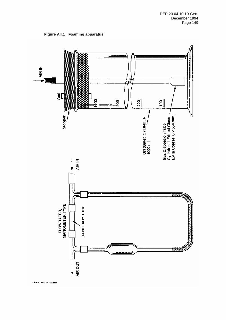
DEP 20.04.10.10-Gen. December 1994
Page 149
Figure AII.1 Foaming apparatus
DEP 20.04.10.10-Gen. December 1994
Page 150
APPENDIX III TESTING OF GLYCOL QUALITY
1. DETERMINATION OF WATER CONTENT
Determination of water content in glycol samples should be in accordance with ASTM D1744.
2. DETERMINATION OF pH
Determination of pH of glycol samples should be in accordance with ASTM D1293.
NOTE: pH determination is done on a glycol sample which has been diluted with an equal volume of distilled
water whose pH has been adjusted to 7.0. Since the dilution is exothermic, care must be taken to calibrate the instrument at the temperature of the solution or, more conveniently, allow the sample to reach room temperature.
3. DETERMINATION OF INORGANIC CHLORIDES CONTENT
Determination of inorganic chloride content in glycol samples should be in accordance with ASTM D512 - Method B.
4. DETERMINATION OF IRON CONTENT
Determination of iron content in glycol samples should be in accordance with ASTM D1068 - Method A.
5. DETERMINATION OF HYDROCARBON CONTENT
Determination of hydrocarbon content should be in accordance with ASTM D3921.
DEP 20.04.10.10-Gen. December 1994
Page 151
APPENDIX IV EVALUATING THE RESULTS OF GLYCOL SAMPLE TESTING The guidelines herein may be used to evaluate laboratory test results of glycol samples.
1. INTERPRETATION OF TEST RESULTS
1.1 Colour of solution Pure glycol is water clear. With use, however, the glycol solution can become discoloured. Generally this discoloration can be attributed to one or more of the following: (i) Thermal decomposition products resulting from excessive reboiler temperatures. See
(3.4.1.2) and (7.4.1).
(ii) Corrosion products resulting from poor pH control.
(iii) Oxidation products resulting from entry of air into the system.
(iv) Solids or corrosion inhibitors in the incoming gas.
(v) The carbon filters are saturated with hydrocarbons and no longer active.
1.2 Water content, weight (%) Generally, the glycol solution must be reconcentrated to a minimum of 99 percent glycol to obtain the desired dewpoint depression in a TEG contactor. If the test report indicates a lower degree of reconcentration, a dewpoint measurement should be made to ascertain that contract quality gas is being delivered by the contactor. If the water specification limit is being exceeded, one or more of the following adjustments should be made: (i) Raise the reboiler temperature to the maximum allowable. See (3.4.1.2) and (7.4.1).
(ii) Increase the gas stripping rate to a maximum of 70 m3(st)/m3 of glycol circulated, if the unit is equipped with gas stripping.
(iii) Increase the UCR to a maximum of 50 litres/kg or until the reboiler cannot maintain the maximum allowable temperature.
(iv) If a glycol-balanced pump is being used, check for leakage from the discharge of the pump back to the suction.
1.3 Hydrocarbon content, vol (%) The hydrocarbon content should be less than one percent by volume. If higher values are reported, check the following. (i) The bulk separator or inlet gas separator may be carrying over.
(ii) A faulty air-cooled lean glycol cooler may lead to condensation of hydrocarbons in the top of the contactor, see (3.5.2.1).
(iii) For best results, the temperature of the glycol at the inlet to the glycol flash vessel should be between 60 °C and 70 °C. The glycol-glycol heat exchangers can become fouled which will prevent the glycol from being heated to this design temperature.
(iv) The glycol solution may be foamy and not separating in the glycol flash vessel. A foaming condition can be detected by determining the length of time required for the foam to dissipate. If the foam seems to be stable it may be necessary to add small amounts of an AF agent to the glycol system, see Appendix II.
(v) The carbon filters are saturated with hydrocarbons, see 1.1 (v) above.
(vi) Feed gas could contain very heavy hydrocarbons which accumulate in the glycol.
(vii) Glycol/condensate separation is poor due to a low separation temperature or a blocked condensate outlet.
DEP 20.04.10.10-Gen. December 1994
Page 152
1.4 Chloride content Any chlorides in the glycol come from salt produced with the gas. The salt may enter the glycol system either through a malfunction of the bulk separator, inlet gas separator or as a result of these vessels being incapable of handling large slugs of liquids. Chlorides increase corrosion and reduce heat transfer in the reboiler and exchangers. Glycol should be cleaned up when the chloride concentration based on water content reaches the saturation limit (approximately 360 g/litre). For TEG with 1 % water this corresponds to 3.6 g/litre NaCl (2.2 g/litre chloride). For DEG with 25% water this corresponds to 90 g/litre NaCl (55 g/litre chloride) in the glycol. Details of methods of removing chlorides are given in Section 5.1.5.4.
1.5 Suspended solids Suspended solids in glycol are usually the result of corrosion caused by a low pH, degradation of the glycol or contamination by the gas stream. The suspended solids content should normally be less than 10 mg/litre. If higher than 100 mg/litre, the inlet gas separator and the glycol filters should be checked.
1.6 pH of solution To prevent corrosion damage to the glycol system, the pH of the glycol/water mixture should be maintained between 6.5 and 8.0. See (5.1.5.3).
1.7 Iron content The iron content is a measure of how much corrosion has occurred in the glycol system. An iron content of 5 ppm is usually the maximum value for a non-corroding glycol system. An iron content of 10-15 ppm would indicate some corrosion products present in the glycol and measures may need to be taken to control corrosion. The iron content should not be allowed to exceed 100 ppm.
DEP 20.04.10.10-Gen. December 1994
Page 153
APPENDIX V TROUBLESHOOTING GAS DEHYDRATION SYSTEMS High water content in the treated gas stream and high glycol losses are the most obvious indications of a gas dehydration unit malfunctioning. This Appendix lists a variety of contributing causes for each.
1. HIGH WATER CONTENT IN TREATED GAS
1.1 Cause - Insufficient glycol circulation rate (i) Gas-glycol powered pump - close lean glycol discharge valve and see if pump
continues to run; if so, it needs to be repaired.
(ii) Gas or electric-driven pump - verify the circulation rate by shutting off glycol discharge from contactor and timing the rate of filling in the column base level gauge.
(iii) Pump stroking but not pumping - check the valves to see if they are seating properly.
(iv) Check pump suction strainer for blockage.
(v) Open bleed valve to eliminate "vapour lock".
(vi) Ensure surge drum level is sufficiently high.
(vii) Check for instrument failure.
(viii) Bubble cap trays leaking.
(ix) Glycol filter plugged - check differential pressure.
(x) Check pump plunger glands for excessive leakage.
1.2 Cause - Insufficient reconcentration If the circulation rate is adequate, check for improper reconcentration. (i) Verify reboiler temperature with a test thermometer and set at the maximum allowable
according to glycol type. See (3.4.1.2) and, if applicable (7.4.1).
(ii) Check glycol-glycol heat exchangers for leakage of wet glycol into the dry glycol.
(iii) Check stripping gas, if applicable, to be sure the flow rate is up to 70 m3(st)/m3.
1.3 Cause - Operating conditions different from design One of the following changes may lead to a reduction in the water content of the treated gas stream. (i) Increase the contactor pressure. This may require installation of a backpressure valve
in the treated gas streams.
(ii) Reduce feed gas temperature, if possible. Check the operation of gas coolers, if applicable.
(iii) Increase the glycol circulation rate, if possible.
(iv) Check the lean glycol temperature feed to the contactor and reduce if necessary, however, note (5.1.5.5).
1.4 Cause - Low gas flow rates (i) If the contactor is trayed and has access manways, blank off a portion of the trays or
bubble caps.
1.5 Cause - Poor glycol distribution (i) With packed columns poor glycol distribution will result in insufficient wetting of the
packing and poor performance. Check alignment of distributor and ensure there are no blockages.
DEP 20.04.10.10-Gen. December 1994
Page 154
2. GLYCOL LOSS
2.1 Cause - Foaming (i) Foaming is often due to contamination of glycol with salt, hydrocarbon, particulates, or
corrosion inhibitor. Check the inlet gas separator and the glycol filters. Remove the source of contamination and if the glycol system is badly contaminated, recharge the system with new glycol.
(ii) Add AF, but be careful not to add too much. See Appendix II.
2.2 Cause - Excessive gas velocity in contactor (i) Decrease gas flow rate.
(ii) Increase the gas pressure in the contactor.
2.3 Cause - Trays plugged with mud, sludge, etc. (i) Plugged trays and/or downcomers usually result in an inability of the liquid to flow
down the column with any appreciable gas flow. If the column has access manways or handholds, manual cleaning is best. If not accessible, the column should be chemically cleaned by a specialist service company.
2.4 Cause - Loss of glycol from the still column (i) Ensure that the surge drum is vented to atmosphere.
(ii) Determine whether free water is entering the contactor with the gas stream and thus overloading the regenerator.
(iii) Clean or replace the still column packing if fouled.
(iv) Add AF, but see Appendix II.
2.5 Cause - Loss of glycol from the glycol flash vessel Trough and weir type flash vessels may have an adjustable glycol weir set too high. This leads to glycol carry-over into the hydrocarbon condensate section.
(i) Check the operation of the glycol outlet line. Where there is total carry-over, the glycol flow control valve will remain closed.
(ii) Take a sample from the hydrocarbon condensate outlet line and analyse for the presence of glycol.
(iii) Lower the glycol weir if glycol carry-over is apparent. It should be set a minimum of 75 mm below that of the condensate weir as shown in Figure 3.16.
DEP 20.04.10.10-Gen. December 1994
Page 155
APPENDIX VI START-UP AND SHUT-DOWN PROCEDURES FOR GAS DEHYDRATION SYSTEMS
This Appendix contains general procedures for the start-up and shut-down of gas dehydration systems.
1. START-UP PROCEDURE
(i) On initial start-up, prior to doing anything read all the information on operation of various components such as controls, pumps, etc. furnished with the unit or system. Study the process and engineering flow schemes.
(ii) Check level controllers and adjust, if necessary. It is generally worthwhile to make a calibration check of temperature and indicating temperature controllers. Check the action of all controllers. Check the set point and action of each alarm and shutdown instrument.
(iii) Verify that all valves are correctly positioned; ensure that all drain valves are closed and all connections are open to liquid level gauge glasses.
(iv) If repair work on the dehydration unit was the reason for the shut-down, verify that all work was completed, i.e. instrument lines reconnected, flanges tightened, etc.
(v) Pressurise the unit and check for leaks. Gas pressure may be required to establish glycol circulation. Confirm that gas is not flowing through the contactor. Check that the contactor LCV is not passing gas.
(vi) Check the lubrication on all valves, pumps, and motors.
(vii) The backpressure regulator on the glycol-condensate separator should be set well below the vessel working pressure. Set the liquid level controls in the separator for maximum level.
(viii) Put oil in the glycol pump if required. Confirm that the packing is installed. Do not excessively tighten the packing retainer, since some types of glycol pumps will leak slightly around the packing. This is necessary for lubrication and a reasonable loss is about 1 litre per day.
(ix) Fill the unit with glycol. Fill the surge drum only half full since the glycol will expand considerably when heated. More glycol may be added after circulation is established. Prime the glycol pumps and ensure the suction lines are gas free. The glycol pump may have to be used in some instances to pump glycol from the surge drum to the rest of the system.
(x) On directly fired reboilers, set the fuel gas regulator initially for about one quarter of the maximum burner pressure. The pressure will have to be increased later to introduce sufficient heat when the operation has stabilised. Check that the glycol level in the reboiler is up to normal and open the pilot valve and light the pilot. Open the valves to the main burners and set the normal temperature controller to about 163 °C for TEG. Adjust the air to the burner to give a blue flame at the burner with a long yellow appearance at the flame tip. The low initial temperature set point is to ensure that the glycol is not overheated during start-up. The normal operating temperature is 190 to 204 °C for TEG.
(xi) On other types of reboilers, follow the above procedure except start the heating fluid flow, introduce steam or hot oil, etc.
(xii) Check the glycol filter to ensure that the filter elements are installed. Open filter block valves, if any.
(xiii) Start the glycol pump.
(xiv) For electric powered pumps, open the recycle valve around the pump. A check valve is located in the pump discharge line near the contactor to prevent gas blowing back to the regenerator when the recycle valve is open. Close the recycle valve to start pumping glycol into the contactor.
DEP 20.04.10.10-Gen. December 1994
Page 156
(xv) For gas powered pumps, open the pump power gas valve and increase the pump gas regulator output until the desired pumping rate is reached. Start the pump lubricator, if fitted.
(xvi) For gas-glycol powered pumps, after opening the low pressure suction and discharge block valves and the high pressure discharge valve to the contactor, start the pump by opening the high pressure suction valve in the discharge line from the contactor. After glycol circulation is established, set the manual speed control valves for the desired glycol flow rate. Since only gas will be going through the high pressure side of the pump initially, care must be taken not to run the pump too fast. Glycol helps lubricate the pump during normal operation, so do not run the pump dry any longer than necessary.
(xvii) If the pumps are gas-locked, bleed off any trapped gas.
(xviii) Check glycol pumping rates by either counting the number of strokes per minute, measuring the shaft speed or by shutting off the manual valve on the contactor glycol outlet line and measuring the glycol accumulation per unit time. The glycol pumping rate must be sufficient for the contactor internals, i.e. in excess of the leakage rate of trays or the minimum for wetting structured packing.
(xix) When sufficient glycol has accumulated in the bottom of the contactor, open the glycol outlet block valve and activate the level controller. Adjust the level controller to the desired level. In the case of gas-glycol powered pumps, no liquid level controller is required. The glycol level will be controlled by the pump at the elevation of the outlet connection.
(xx) Check the glycol concentration and reboiler temperature prior to starting gas flow into the contactor. Increase contactor pressure slowly to line pressure and gradually start the gas flow, increasing to the desired rate. If the gas is turned into the contactor too rapidly, it will carry over substantial amounts of glycol into the gas stream. At least 10 minutes should be allowed to build up gas flow into the contactor. This time may vary as operators becomes familiar with the system. Particular care should be taken when gas from a compressor is being dehydrated. The gas flow should not be started until the glycol circulation has been established and the reconcentrator is up to temperature.
(xxi) When gas flow is established, increase the reboiler temperature controller to the design set point.
(xxii) If the regenerator is a high concentration type employing stripping gas, start the stripping gas flow. The stripping gas should be adjusted to give the flow rate shown on the process mechanical flow sheet.
(xxiii) Adjust the glycol flash vessel level controller to maintain a level in the middle of the gauge glass. Note that it may take several hours for sufficient condensate to accumulate in the separator to require dumping. Do not allow the glycol to spill over into the condensate section of the vessel. This is a common source of glycol loss. Adjust the glycol level control to hold level in middle of gauge glass. Adjust the backpressure controller to the design pressure.
(xxiv) When temperatures and flow rates stabilise, fill the glycol surge drum approximately two-thirds full. Mark the liquid level on the gauge glass. Glycol consumption can be measured by recording the volume required to refill to this mark.
(xxv) Make frequent checks of temperature, pressures, pump rate, and liquid levels during the first few hours of operation. In particular, monitor the filter differential pressure gauge as fouling will initially be rapid unless exceptional cleanliness has been observed during erection or maintenance.
(xxvi) Monitor the pump gland leakage. Adjust the plunger packings to allow only a slow drip leakage of glycol.
(xxvii) Monitor the pH of the glycol to ensure that the solution is properly buffered.
DEP 20.04.10.10-Gen. December 1994
Page 157
2. SHUT-DOWN PROCEDURE
(i) Check temperatures, pressures, pumping rate, and liquid levels, making a note of any abnormalities. This brief check will be useful for solving problems and will save time when returning the system to operation.
(ii) Stop the gas flow through the contactor.
(iii) Turn off the heat supply to the reboiler.
(iv) Continue to circulate glycol for a minimum of 5 minutes to prevent overheating the glycol.
(v) Stop the glycol pump.
(vi) Close the condensate outlet valve on the glycol flash vessel. Closing the block valve will prevent glycol from being lost through the condensate level control valve. This also prevents loss of glycol if the unit is re-started too rapidly.
Amended per Circular 57/03
NOTE: For H2S services, in addition to the above start-up and shut-down procedures, the safety precautions described in EP 95-0317 should be adhered to.
DEP 20.04.10.10-Gen. December 1994
Page 158
APPENDIX VII MAINTENANCE OF GAS DEHYDRATION SYSTEMS This Appendix contains a list of general items for periodic maintenance, including particular advice for pump maintenance.
1. PERIODIC MAINTENANCE
The following items should be checked periodically: (i) Eliminate any excessive vibration of the unit, especially on level and temperature
controllers and pump suction and discharge lines.
(ii) Make a frequent check of levels, temperatures, pressure and pumping rate. These data will be valuable for diagnosing problems and preventing any unnecessary shut-downs.
(iii) Examine the fire box in direct fired reboilers to ensure that the flame is not impinging on the sidewall.
(iv) Ensure that the butterfly valve in the exhaust line to the heating chamber seals tightly in exhaust heat recovery reboilers. Exhaust leakage into the chamber when the unit is shut down will overheat the glycol and cause severe thermal degradation.
(v) Stock sufficient spare glycol filter elements, level control floats, and any other items that are subject to failure and could force a shut-down.
(vi) Become familiar with the service manual furnished with the dehydration system. It describes in detail the maintenance procedures for pumps, level controls and other accessory equipment.
(vii) Change the glycol particle filter elements whenever the pressure drop across the filter reaches 170 kPa or at least every 3 to 6 months
(viii) Maintain good housekeeping. It aids in showing leaks and allows better operation.
(ix) When a shut-down is scheduled, trip one of the shut-downs manually. If the shut-down system is not operated occasionally, it may tend to be sluggish or fail to function.
(x) Add glycol as needed to the surge vessel. Never fill to more than two-thirds full.
(xi) Repair leaks immediately; continuous dripping will result in appreciable losses of glycol.
(xii) Blow out the glycol strainers regularly for cleaning; save the glycol and put it back into the storage tank or surge drum.
(xiii) Clean the fire tube or heating chamber tube as needed.
(xiv) Lubricate pumps as required.
(xv) Take a sample of lean glycol for analysis every 3 months.
(xvi) Check gas-blanketed vessels regularly for the correct pressure and flow of blanketing gas.
2. PUMP MAINTENANCE
(i) Carefully starting a new pump can prevent poor operation and down time. The pump must always be primed full of glycol before attempting to start it.
A reciprocating pump packing gland generally is lubricated only by the glycol itself. The packing is dry when the pump is new. As it soaks up glycol, the packing tends to expand. If the packing has been screwed down too tight, either the plunger will be scored or the packing will burn out. One of the most common sources of glycol loss occurs at the pump packing gland. If the pump leaks about two litres of glycol per day, the packing probably needs replacing. The packing should be installed hand tight and then backed off one complete turn. The gland should be adjusted such that no more
DEP 20.04.10.10-Gen. December 1994
Page 159
Last page of this DEP
than one drop per minute leaks from the gland. When the gland becomes fully tightened and the leakage rate continues to increase, it is time to replace the gland packing. On pumps over 100 kW, gland inspection and adjustment should be performed daily. See also Appendix VI, 1 (xxvi).
(ii) The pump is handling a fluid that frequently becomes dirty and corrosive. Cylinder corrosion, pump plunger cup and ring wear and sticking or plugged valves must be detected and corrected to keep the pump at maximum efficiency.
(iii) If gas-glycol pumps are used, the pump rate should be commensurate with the gas volume being processed. The speed should be decreased for low gas rates and increased for high rates. The rate should be checked regularly by timing the pump to make sure it is running at the proper speed.
(iv) When the pump check valves become worn or clogged, the positive displacement pump will give the appearance of operating normally except that no fluid flows to the contactor. A pressure gauge will still indicate that the pump is pumping. The only evidence of this type of failure is little or no dewpoint depression. One way to check the volume being pumped is to shut the valve on the contactor outlet and calculate the flow by measuring the rise in the gauge glass. If the flow is less than normal, inspect the pump valves.
(v) If there is insufficient glycol circulation the pump suction strainer should also be checked for plugging and/or the bleeder valve should be opened to eliminate "vapour lock".
Related Documents