Global technical regulation No. 13 Global technical regulation on hydrogen and fuel cell vehicles 世界統一技術規則第 13 号 水素及び燃料電池自動車に関する世界統一規則 Contents 目次 I. Statement of technical rationale and justification I. 技術的論拠及び正当性 A. Introduction A. 序 B. gtr action plan B. gtr アクションプラン C. Description of typical hydrogen-fuelled fuel cell vehicles (HFCVs) 1. Vehicle description 2. Hydrogen fuelling system 3. Hydrogen storage system 4. Hydrogen fuel delivery system 5. Fuel cell system 6. Electric propulsion and power management system C. 一般的な水素燃料電池自動車(HFCV)の説明 1. 車両の説明 2. 水素燃料供給システム 3. 水素貯蔵システム 4. 水素燃料輸送システム 5. 燃料電池システム 6. 電気推進及び電力管理システム D. Rationale for scope, definitions and applicability 1. Rationale for paragraph 2. (Scope) 2. Rationale for paragraphs 3.9. and 3.48. (Definitions of service life and date of removal from service) 3. Rationale for paragraph 4. (Applicability of requirements) D. 適用範囲、定義、及び適用性の論拠 1. 2 項(適用範囲)の論拠 2. 3.9 項及び 3.48 項(耐用期間及びサービス停止日の定義)の論拠 3. 4 項(要求事項の適用性)の論拠 E. Rationale for paragraph 5. (Performance requirements) 1. Compressed hydrogen storage system requirements and safety needs 2. Vehicle fuel system requirements and safety needs 3. Electrical safety requirements and safety needs E. 5 項(性能要件)の論拠 1. 圧縮水素貯蔵システムの試験要件及び安全ニーズ 2. 車両の燃料システム要件及び安全ニーズ 3. 電気的安全要件と安全ニーズ F. Rationale for storage and fuel system test procedures 1. Rationale for storage and fuel system integrity tests 2. Rationale for paragraph 6.2. (Test procedures for compressed hydrogen storage systems) F. 貯蔵及び燃料システムの試験手順の論拠 1. 貯蔵及び燃料システムの完全性に関する試験の論拠 2. 6.2 項(圧縮水素貯蔵システムの試験手順)の論拠 G. Optional requirements: vehicles with liquefied hydrogen storage G. 任意の要求事項:液体水素貯蔵システムを搭載した車両/論拠

Welcome message from author
This document is posted to help you gain knowledge. Please leave a comment to let me know what you think about it! Share it to your friends and learn new things together.
Transcript
Global technical regulation No. 13
Global technical regulation on hydrogen and fuel cell vehicles
世界統一技術規則第 13 号
水素及び燃料電池自動車に関する世界統一規則
Contents 目次
I. Statement of technical rationale and justification I. 技術的論拠及び正当性
A. Introduction A. 序
B. gtr action plan B. gtr アクションプラン
C. Description of typical hydrogen-fuelled fuel cell vehicles (HFCVs)
1. Vehicle description
2. Hydrogen fuelling system
3. Hydrogen storage system
4. Hydrogen fuel delivery system
5. Fuel cell system
6. Electric propulsion and power management system
C. 一般的な水素燃料電池自動車(HFCV)の説明
1. 車両の説明
2. 水素燃料供給システム
3. 水素貯蔵システム
4. 水素燃料輸送システム
5. 燃料電池システム
6. 電気推進及び電力管理システム
D. Rationale for scope, definitions and applicability
1. Rationale for paragraph 2. (Scope)
2. Rationale for paragraphs 3.9. and 3.48. (Definitions of service life and date of
removal from service)
3. Rationale for paragraph 4. (Applicability of requirements)
D. 適用範囲、定義、及び適用性の論拠
1. 2 項(適用範囲)の論拠
2. 3.9 項及び 3.48 項(耐用期間及びサービス停止日の定義)の論拠
3. 4 項(要求事項の適用性)の論拠
E. Rationale for paragraph 5. (Performance requirements)
1. Compressed hydrogen storage system requirements and safety needs
2. Vehicle fuel system requirements and safety needs
3. Electrical safety requirements and safety needs
E. 5 項(性能要件)の論拠
1. 圧縮水素貯蔵システムの試験要件及び安全ニーズ
2. 車両の燃料システム要件及び安全ニーズ
3. 電気的安全要件と安全ニーズ
F. Rationale for storage and fuel system test procedures
1. Rationale for storage and fuel system integrity tests
2. Rationale for paragraph 6.2. (Test procedures for compressed hydrogen storage
systems)
F. 貯蔵及び燃料システムの試験手順の論拠
1. 貯蔵及び燃料システムの完全性に関する試験の論拠
2. 6.2 項(圧縮水素貯蔵システムの試験手順)の論拠
G. Optional requirements: vehicles with liquefied hydrogen storage G. 任意の要求事項:液体水素貯蔵システムを搭載した車両/論拠
systems/rationale
1. Background information for liquefied hydrogen storage systems
2. Rationale for liquefied hydrogen storage system design qualification
requirements of paragraph 7.2
3. Rationale for vehicle fuel system design qualification requirements (LH2)
4. Rationale for test procedures for LHSSs
5. Rationale for paragraph 7.5. (Test procedure for post-crash
concentration measurement for vehicles with liquefied hydrogen storage
systems (LHSSs))
1. 液体水素貯蔵システムに関する基本的情報
2. 7.2 項の液体水素貯蔵システムの設計承認に関する要求事項の論拠
3. 車両の燃料システムの設計認定に関する要求事項の論拠(LH2)
4. LHSS の試験手順の論拠
5. 7.5 項の論拠(液体水素貯蔵システム(LHSS)を搭載した車両における衝突後
の濃度測定の試験手順)
H. National provisions for material compatibility (including hydrogen
embrittlement) and conformity of production
1. Material compatibility and hydrogen embrittlement
2. National requirements complimentary to gtr requirements
H. 材質の適合性(水素脆化を含めた)及び生産の適合性に関する国内規定
1. 材質の適合性及び水素脆化
2. gtr の要求事項を補足する国内要求事項
I. Topics for the next phase in developing the gtr for hydrogen-fuelled vehicles I. 水素燃料自動車に関する gtr 策定の次のフェーズにおける課題
J. Existing Regulations, Directives, and International Standards
1. Vehicle fuel system integrity
2. Storage system
3. Electric safety
J. 既存の規制、指令、及び国際規格
1. 車両の燃料システムの完全性
2. 貯蔵システム
3. 電気的安全
K. Benefits and Costs K. 便益と費用
II. Text of the Regulation II. 規則本文
1. Purpose
2. Scope
3. Definitions
4. Applicability of requirements
5. Performance requirements
5.1. Compressed hydrogen storage system
5.2. Vehicle fuel system
1. 目的
2. 適用範囲
3. 定義
4. 要求事項の適用性
5. 性能要件
5.1. 圧縮水素貯蔵システム
5.2. 車両の燃料システム
5.3. Electrical safety
6. Test conditions and procedures
6.1. Compliance tests for fuel system integrity
6.2. Test procedures for compressed hydrogen storage
6.3. Test procedures for electrical safety
7. Vehicles with liquefied hydrogen storage systems (LHSSs)
7.1. LHSS optional requirements
7.2. LHSS design qualification requirements
7.3. LHSS fuel system integrity
7.4. Test procedures for LHSS design qualification
7.5. Test procedures for LHSS fuel system integrity
5.3. 電気的安全
6. 試験条件と手順
6.1. 燃料システムの完全性に関する適合試験
6.2. 圧縮水素貯蔵の試験手順
6.3. 電気的安全に関する試験手順
7. 液体水素貯蔵システム(LHSS)を搭載した車両
7.1. LHSS に関する任意の要求事項
7.2. LHSS の設計認定要件
7.3. LHSS 燃料システムの完全性
7.4. LHSS の設計認定試験手順
7.5. LHSS 燃料システムの完全性に関する試験手順
I. Statement of technical rationale and justification I. 技術的論拠及び正当性
A. Introduction A. 序
1. In the ongoing debate over the need to identify new sources of energy and to
reduce greenhouse gas emissions, companies around the world have explored the
use of various alternative fuels, including compressed natural gas, liquefied
propane gas and hydrogen. Hydrogen has emerged as one of the most promising
alternatives due to its vehicle emissions being virtually zero. In the late 1990s, the
European Community allocated resources to study the issue under its European
Integrated Hydrogen Project (EIHP) and forwarded the results, two proposals for
compressed gaseous and liquefied hydrogen, to the UNECE secretariat. The
follow-up project, EIHP2, initiated discussions about the possibility of a global
technical regulation for hydrogen fuelled vehicles. A few years later, the United
States of America outlined a vision for a global initiative, the International
Partnership for the Hydrogen Economy, and invited China, Japan, the Russian
Federation, the European Union and many other countries to participate in this
1. 新しいエネルギー源の発見と温室効果ガスの排出削減を求める議論が続けら
れる中、世界中の各企業は圧縮天然ガス、液化プロパンガス、及び水素を含む各
種代替燃料の活用を研究してきた。水素は車両排出ガスが実質的にゼロであるこ
とから、 も有望な代替燃料の 1 つとして浮上した。1990 年代後半、欧州共同体
は欧州統合水素プロジェクト(EIHP)のもとでこれを調査する人員を配置し、そ
の成果として圧縮水素ガス及び液体水素に関する 2 つの提案を UNECE 事務局に
提出した。フォローアッププロジェクトである EIHP2 は、水素燃料自動車の世界
統一基準の可能性について議論を開始した。数年後、アメリカ合衆国は国際的イ
ニシアティブ構想の概要である「水素経済のための国際パートナーシップ」をま
とめ、中国、日本、ロシア連邦、欧州連合、及びその他の多くの国に対しこの取
り組みへの参加を促した。
effort.
2. For decades scientists, researchers and economists have pointed to hydrogen, in
both compressed gaseous and liquid forms, as a possible alternative to gasoline and
diesel as a vehicle fuel. Ensuring the safe use of hydrogen as a fuel is a critical
element in successful transitioning to a global hydrogen economy. By their nature,
all fuels present an inherent degree of danger due to their energy content. The safe
use of hydrogen, particularly in the compressed gaseous form, lies in preventing
catastrophic failures involving a combination of fuel, air and ignition sources as
well as pressure and electrical hazards.
2. 数十年にわたり科学者、研究者及び経済学者は、ガソリン及びディーゼルに代
わる車両燃料として圧縮水素ガス及び液体水素の両方に注目してきた。地球規模
の水素経済への転換を成功させるためには、燃料としての水素の使用に際して、
安全性の確保が重要な要素である。元来、すべての燃料は含有しているエネルギ
ーにより危険性を伴うものである。水素、特に圧縮水素ガスの安全な活用は、燃
料、空気、及び点火源の組み合わせ、また圧力及び電気的障害に関連する破局故
障を防げるか否かにかかっている。
3. Governments have identified the development of regulations and standards as
one of the key requirements for commercialization of hydrogen-fuelled vehicles.
Regulations and standards will help overcome technological barriers to
commercialization, facilitate manufacturers’ investment in building
hydrogen-fuelled vehicles and facilitate public acceptance by providing a
systematic and accurate means of assessing and communicating the risk associated
with the use of hydrogen vehicles, be it to the general public, consumer, emergency
response personnel or the insurance industry.
3. 各国政府は、水素燃料自動車の商業化において規制及び基準の策定が重要要件
の 1 つであることを確認した。規制及び基準は、商業化に向けた技術的障害の克
服を支援し、水素燃料自動車の製造への投資をメーカーに促し、水素自動車の使
用に伴う危険を体系的かつ正確に評価し伝達する手段を一般市民、消費者、緊急
対応人員、保険業界に提供することによりパブリックアクセプタンスを促す。
4. The development of this United Nations global technical regulation (gtr) for
Hydrogen and Fuel Cell Vehicles occurred within the World Forum for
Harmonization of Vehicle Regulations (WP.29) of the Inland Transport Committee
(ITC) of UNECE. The goals of this global technical regulation (gtr) are to develop
and establish a gtr for hydrogen-fuelled vehicles that: (i) attains or exceeds the
equivalent levels of safety of those for conventional gasoline fuelled vehicles; and
(ii) is performance-based and does not restrict future technologies.
4. 水素及び燃料電池自動車に関する国連世界統一基準(gtr)の策定は、UNECE
内陸運輸委員会(ITC)の自動車基準調和世界フォーラム(WP.29)で発案された。
この世界統一基準(gtr)の目的は、(i)従来型のガソリン燃料車の安全レベルと同
等若しくはそれ以上の安全性を備えている水素燃料自動車、及び(ii)性能ベースで
あり、将来的な技術を制限しない水素燃料自動車の gtr を策定、確立することで
ある。
B. gtr action plan B. gtr アクションプラン
5. Given that hydrogen-fuelled vehicle technology is still emerging, the Executive 5. 水素燃料自動車の技術はまだ新しい技術であることから、WP.29 の 1998 年合
Committee of the 1998 Agreement (WP.29/AC.3) of WP.29 agreed that input from
researchers is a vital component of this effort. Using existing regulations and
standards of hydrogen and fuel cell vehicles (HFCVs) and conventional vehicles as
a guide, it is important to investigate and consider: (1) the main differences
between conventional vehicles and hydrogen-fuelled vehicles in safety and
environmental issues; and, (2) the technical justification for requirements that
would be applied to hydrogen-fuelled vehicles.
意の執行委員会(WP.29/AC.3)は、この取り組みにおいては研究者の協力が不可
欠であるということで合意した。水素及び燃料電池自動車(HFCV)、及び従来型
の自動車に関する既存の規制及び基準を参考にし、(1)従来型の自動車と水素燃料
自動車の安全性と環境問題における主な違い、及び(2)水素燃料自動車に適用され
る要件の技術的正当性について調査、考慮することが重要である。
6. In June 2005, WP.29/AC.3 agreed to a proposal from Germany, Japan and
United States of America regarding how best to manage the development process
for a gtr on hydrogen-fuelled vehicles (ECE/TRANS/WP.29/AC.3/17). Under the
agreed-upon process, AC.3 approved an action plan for developing a gtr submitted
by the co-sponsors. Two subgroups were formed to address the safety and the
environment aspects of the gtr. The informal working subgroup on safety for
hydrogen and fuel cell vehicles (HFCV-SGS) reported to the WP.29 subsidiary
Working Party on Passive Safety (GRSP). HFCV-SGS was chaired by Japan and
the United States of America. The Chair for the group was designated in the
summer of 2007. The environmental subgroup (HFCV-SGE) was chaired by the
European Commission and reported to the WP.29 subsidiary Working Party on
Pollution and Energy (GRPE). In order to ensure communication between the
subgroups and continuous engagement with WP.29 and AC.3, the project manager
(Germany) coordinated and managed the various aspects of the work to ensure that
the agreed action plan was implemented properly and that milestones and timelines
were set and met throughout the development of the gtr. The initial stage of the gtr
covered fuel cell (FC) and internal combustion engine (ICE), compressed gaseous
hydrogen (CGH2) and liquid hydrogen (LH2) gtr. At a subsequent session of
WP.29, the gtr action plan was submitted and approved by AC.3
(ECE/TRANS/WP.29/2007/41).
6. 2005 年 6 月、WP.29/AC.3 は、ドイツ、日本、及びアメリカ合衆国が提案した、
水素燃料自動車に関する gtr(ECE/TRANS/WP.29/AC.3/17)策定プロセスを効果
的に行う方法に同意した。合意されたプロセスに従い、AC.3 は共同提案者が提
出した gtr 策定に関するアクションプランを承認した。当該 gtr の安全面及び環境
面を扱う 2 つのサブグループが組織された。水素及び燃料電池自動車の安全に関
する非公式サブグループ(HFCV-SGS)は、WP.29 の補助組織である衝突安全分
科会(GRSP)に直属している。HFCV-SGS の議長国は日本とアメリカ合衆国で
あった。当該部会の議長国は 2007 年の夏に指名された。環境関連のサブグルー
プ(HFCV-SGE)の議長国は欧州委員会であり、WP.29 の補助組織である排出ガ
ス・エネルギー分科会(GRPE)に直属している。サブグループ間のコミュニケ
ーションと WP.29 及び AC.3 との関与を確実にするため、プロジェクトマネージ
ャ(ドイツ)が作業の各側面における調整及び管理を行い、gtr 策定プロセス全
体を通じて、合意されたアクションプランが適切に実施され、マイルストーン及
びスケジュールの設定と遵守が徹底されるようにした。gtr の第一段階は、燃料
電池(FC)及び内燃エンジン(ICE)、圧縮水素ガス(CGH2)及び液体水素(LH2)
gtr を扱っている。WP.29 の次のセッションでは、gtr アクションプランが提出さ
れ、AC.3 により承認された。(ECE/TRANS/WP.29/2007/41)
7. In order to develop the gtr in the context of evolving hydrogen technologies, the
trilateral group of co-sponsors proposes to develop the gtr in two phases:
(a) Phase 1 (gtr for hydrogen-fuelled vehicles):
Establish a gtr by 2010 for hydrogen-fuelled vehicles based on a combination of
component-, subsystem-, and vehicle-level requirements. The gtr specifies that
each Contracting Party will use its existing national crash tests where vehicle crash
tests are required, but and will use the agreed upon maximum allowable level of
hydrogen leakage as the crash test leakage requirement. The new Japanese national
regulation, any available research and test data will be used as a basis for
developing this first phase of the gtr.
(b) Phase 2 (Assess future technologies and harmonize crash tests):
Amend the gtr to maintain its relevance with new findings based on new research
and the state of the technology beyond phase 1. Discuss how to harmonize crash
test requirements for HFCV regarding whole vehicle crash testing for fuel system
integrity.
7. 水素技術の発展との関連において gtr を策定するため、3 グループから成る共
同提案者が 2 段階での gtr 策定を提案した。
(a) 第 1 段階(水素燃料自動車用の gtr)
2010 年までに、構成部品レベル、サブシステムレベル、車両レベルの要求事項に
基づく水素燃料自動車用の gtr を策定する。gtr は、衝突試験が要求される場合は、
各締約国が既存の国内向け衝突試験を使用するが、衝突試験の漏出に関する要件
として、合意された 大許容水素漏出レベルを使用することを定めている。gtr
の第 1 段階策定のベースとして、新しい日本の国内規制、入手可能な既存の調査
及び試験データを使用する。
(b) 第 2 段階(将来的な技術の評価と衝突試験の調和)
第 1 段階以降の 新の調査及び技術に基づき、新しい知見との関連性を維持する
ため gtrを改訂する。燃料システムの完全性に関する車両衝突試験におけるHFCV
の衝突試験要件を調和させる方法を議論する。
8. The gtr will consist of the following key elements:
(a) Component and subsystem level requirements (non-crash test based):
Evaluate the non-crash requirements by reviewing analyses and evaluations
conducted to justify the requirements. Add and subtract requirements or amend test
procedures as necessary, based on existing evaluations or on quick evaluations that
could be conducted by Contracting Parties and participants. Avoid design specific
requirements to the extent possible and do not include provisions that are not
technically justified. The main areas of focus are:
(i) Performance requirements for hydrogen storage systems, high-pressure
closures, pressure relief devices, and fuel lines;
(ii) Electrical isolation, safety and protection against electric shock (in use);
(iii) Performance and other requirements for subsystem integration in the vehicle.
8. gtr は主に以下の主要要素で構成されている。
(a) 構成部品及びサブシステムレベルの要求事項(非衝突試験ベース)
要求事項の正当性を証するために実施した分析及び評価を審査して非衝突要件
を評価する。既存の評価あるいは締約国及び参加国が実施する迅速評価により、
必要に応じて試験手順をを追加、削除、又は修正する。特定設計の要求事項は可
能な限り避け、技術的に正当化されていない規定は含めない。主に焦点となる領
域は以下の通り。
(i) 水素貯蔵システム、高圧エンクロージャ、圧力除去装置、及び燃料管路の性
能要件
(ii) 電気的遮蔽、(使用時の)感電に対する安全及び保護
(iii) 車両へのサブシステム統合に関する性能及びその他の要求事項
(b) Vehicle-level requirements:
Examine the risks posed by the different types of fuel systems in different crash
modes. Review and evaluate analyses and crash tests conducted to examine the
risks and identify appropriate mitigating measures for hydrogen-fuelled vehicles.
The main areas of focus are as follows:
(i) In-use and post-crash limits on hydrogen releases. Post-crash leakage limits
apply following execution of crash tests (front, side and rear) that are specified in
national requirements for crash safety testing in each jurisdiction;
(ii) In-use and post-crash requirements for electrical isolation and protection
against electric shock. Post-crash electrical safety criteria apply following
execution of crash tests (front, side and rear) that are specified in national
requirements for crash safety testing in each jurisdiction.
(b) 車両レベルの要求事項
異なる衝突条件における異なる種類の燃料システムに起因するリスクを検討す
る。リスクの評価においては、分析及び実施した衝突試験を考察、評価し、水素
燃料自動車におけるリスク低減の適切な手段を特定する。主に焦点となる領域は
以下の通り。
(i) 使用中及び衝突後の水素放出の制限。衝突後の漏出限界は、各国の法規に従
った衝突安全試験に関する国内要件に規定されている衝突試験(前面、側面、後
面)実施後に適用される。
(ii) 使用中及び衝突後の電気的遮蔽及び感電に対する保護に関する要求事項。衝
突後の電気的安全基準は、各国の法規に従った衝突安全試験に関する国内要件に
規定されている衝突試験(前面、側面、後面)実施後に適用される。
C. Description of typical hydrogen-fuelled fuel cell vehicles (HFCVs) C. 一般的な水素燃料電池自動車(HFCV)の説明
1. Vehicle description 1. 車両の説明
9. Hydrogen fuelled vehicles can use either internal combustion engine (ICEs) or
fuel cells to provide power; however, hydrogen-fuelled vehicles are typically
powered by fuel cell power systems. Hydrogen-fuelled fuel cell vehicles (HFCVs)
have an electric drive-train powered by a fuel cell that generates electric power
electrochemically using hydrogen. In general, HFCVs are equipped with other
advanced technologies that increase efficiency, such as regenerative braking
systems that capture the kinetic energy lost during braking and store it in a battery
or ultra-capacitors. While the various HFCVs are likely to differ in the details of
the systems and hardware/software implementations, the following major systems
are common to most HFCVs:
(a) Hydrogen fuelling system;
(b) Hydrogen storage system;
9. 水素燃料自動車は、内燃エンジン(ICE)又は燃料電池のいずれ
かを使って電力を供給することができるが、一般的に水素燃料自動
車は、燃料電池電力システムにより電力を供給する。水素燃料電池
自動車(HFCV)は、水素を使って電気化学的に電力を発生させる
燃料電池により作動する電気駆動系を搭載している。一般的に
HFCV は、効率を向上させるその他の先進技術、例えば制動時に失
われる運動エネルギーを回収し、これをバッテリーあるはウルトラ
キャパシタに蓄積する回生制動装置を搭載している。各種の HFCV
は、システム及びハードウェア/ソフトウェア実装の細部は異なる
ことはあっても、多くの HFCV において以下の主要システムは共通
している。
(a) 水素燃料供給システム
(c) Hydrogen fuel delivery system;
(d) Fuel cell system;
(e) Electric propulsion and power management system.
(b) 水素貯蔵システム
(c) 水素燃料輸送システム
(d) 燃料電池システム
(e) 電気推進、電力管理システム
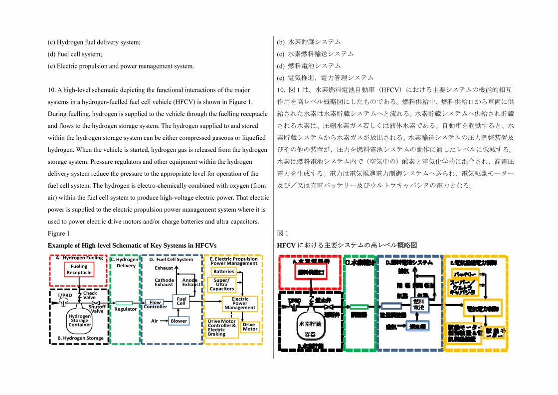
10. A high-level schematic depicting the functional interactions of the major
systems in a hydrogen-fuelled fuel cell vehicle (HFCV) is shown in Figure 1.
During fuelling, hydrogen is supplied to the vehicle through the fuelling receptacle
and flows to the hydrogen storage system. The hydrogen supplied to and stored
within the hydrogen storage system can be either compressed gaseous or liquefied
hydrogen. When the vehicle is started, hydrogen gas is released from the hydrogen
storage system. Pressure regulators and other equipment within the hydrogen
delivery system reduce the pressure to the appropriate level for operation of the
fuel cell system. The hydrogen is electro-chemically combined with oxygen (from
air) within the fuel cell system to produce high-voltage electric power. That electric
power is supplied to the electric propulsion power management system where it is
used to power electric drive motors and/or charge batteries and ultra-capacitors.
10. 図 1 は、水素燃料電池自動車(HFCV)における主要システムの機能的相互
作用を高レベル概略図にしたものである。燃料供給中、燃料供給口から車両に供
給された水素は水素貯蔵システムへと流れる。水素貯蔵システムへ供給され貯蔵
される水素は、圧縮水素ガス若しくは液体水素である。自動車を起動すると、水
素貯蔵システムから水素ガスが放出される。水素輸送システムの圧力調整装置及
びその他の装置が、圧力を燃料電池システムの動作に適したレベルに低減する。
水素は燃料電池システム内で(空気中の)酸素と電気化学的に混合され、高電圧
電力を生成する。電力は電気推進電力制御システムへ送られ、電気駆動モーター
及び/又は充電バッテリー及びウルトラキャパシタの電力となる。
Figure 1
Example of High-level Schematic of Key Systems in HFCVs
図 1
HFCV における主要システムの高レベル概略図
FuelingReceptacle
CheckValveT/PRD
ShutoffValve
HydrogenStorageContainer
A. Hydrogen Fueling
B. Hydrogen Storage
C. HydrogenDelivery
Regulator
D. Fuel Cell System
FlowController
Exhaust
AnodeExhaust
CathodeExhaust
Blower
FuelCell
E. Electric PropulsionPower Management
Batteries
Super/Ultra
Capacitors
ElectricPower
Management
DriveMotor
Drive MotorController &ElectricBraking
Z
Air
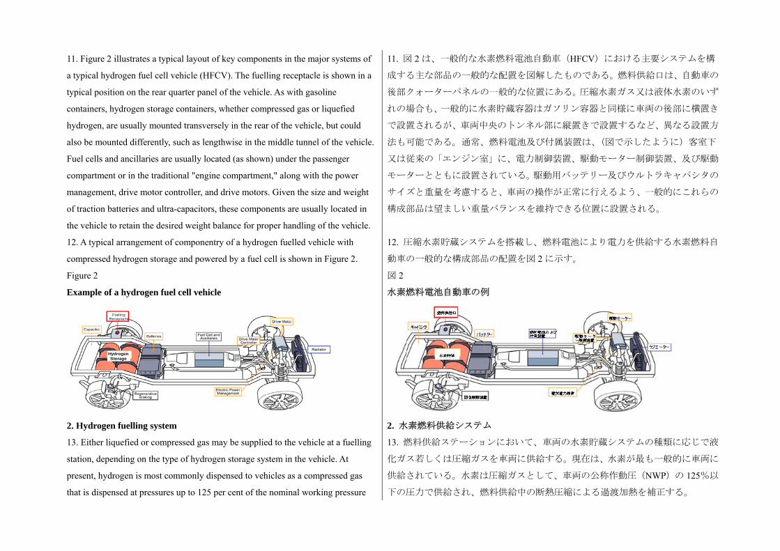
11. Figure 2 illustrates a typical layout of key components in the major systems of
a typical hydrogen fuel cell vehicle (HFCV). The fuelling receptacle is shown in a
typical position on the rear quarter panel of the vehicle. As with gasoline
containers, hydrogen storage containers, whether compressed gas or liquefied
hydrogen, are usually mounted transversely in the rear of the vehicle, but could
also be mounted differently, such as lengthwise in the middle tunnel of the vehicle.
Fuel cells and ancillaries are usually located (as shown) under the passenger
compartment or in the traditional "engine compartment," along with the power
management, drive motor controller, and drive motors. Given the size and weight
of traction batteries and ultra-capacitors, these components are usually located in
the vehicle to retain the desired weight balance for proper handling of the vehicle.
11. 図 2 は、一般的な水素燃料電池自動車(HFCV)における主要システムを構
成する主な部品の一般的な配置を図解したものである。燃料供給口は、自動車の
後部クォーターパネルの一般的な位置にある。圧縮水素ガス又は液体水素のいず
れの場合も、一般的に水素貯蔵容器はガソリン容器と同様に車両の後部に横置き
で設置されるが、車両中央のトンネル部に縦置きで設置するなど、異なる設置方
法も可能である。通常、燃料電池及び付属装置は、(図で示したように)客室下
又は従来の「エンジン室」に、電力制御装置、駆動モーター制御装置、及び駆動
モーターとともに設置されている。駆動用バッテリー及びウルトラキャパシタの
サイズと重量を考慮すると、車両の操作が正常に行えるよう、一般的にこれらの
構成部品は望ましい重量バランスを維持できる位置に設置される。
12. A typical arrangement of componentry of a hydrogen fuelled vehicle with
compressed hydrogen storage and powered by a fuel cell is shown in Figure 2.
12. 圧縮水素貯蔵システムを搭載し、燃料電池により電力を供給する水素燃料自
動車の一般的な構成部品の配置を図 2 に示す。
Figure 2
Example of a hydrogen fuel cell vehicle
図 2
水素燃料電池自動車の例
2. Hydrogen fuelling system
13. Either liquefied or compressed gas may be supplied to the vehicle at a fuelling
station, depending on the type of hydrogen storage system in the vehicle. At
present, hydrogen is most commonly dispensed to vehicles as a compressed gas
that is dispensed at pressures up to 125 per cent of the nominal working pressure
2. 水素燃料供給システム
13. 燃料供給ステーションにおいて、車両の水素貯蔵システムの種類に応じで液
化ガス若しくは圧縮ガスを車両に供給する。現在は、水素が も一般的に車両に
供給されている。水素は圧縮ガスとして、車両の公称作動圧(NWP)の 125%以
下の圧力で供給され、燃料供給中の断熱圧縮による過渡加熱を補正する。
HydrogenStorage
HydrogenStorage
FuelingReceptacle
(NWP) of the vehicle to compensate for transient heating from adiabatic
compression during fuelling.
14. Regardless of the state of the hydrogen, the vehicles are fuelled through a
special fuelling nozzle on the fuel dispenser at the fuelling station that connects
with the fuelling receptacle on the vehicle to provide a "closed system" transfer of
hydrogen to the vehicle. The fuelling receptacle on the vehicle contains a check
valve (or other device) that prevents leakage of hydrogen out of the vehicle when
the fuelling nozzle is disconnected.
14. 水素の状態に関係なく、燃料供給ステーションの燃料供給機の特殊ノズルを
車両の燃料供給口へ接続して「閉鎖系」を形成し、水素を車両に供給する。車両
の燃料供給口には、燃料供給ノズルを外した時に車両から水素が漏出することを
防止するための逆止弁(若しくはその他の装置)が設置されている。
3. Hydrogen storage system
15. The hydrogen storage system consists of all components that form the primary
high pressure boundary for containment of stored hydrogen. The key functions of
the hydrogen storage system are to receive hydrogen during fuelling, contain the
hydrogen until needed, and then release the hydrogen to the fuel cell system for use
in powering the vehicle. At present, the most common method of storing and
delivering hydrogen fuel on-board is in compressed gas form. Hydrogen can also
be stored as liquid (at cryogenic conditions). Each of these types of hydrogen
storage systems are described in the following sections.
3. 水素貯蔵システム
15. 水素貯蔵システムは、貯蔵水素を閉じ込める一次高圧力バウンダリを形成す
るすべての構成部品で構成されている。水素貯蔵システムの主要機能は、燃料供
給時に水素を受け入れ、使用するまでの間水素を貯蔵し、車両に動力を供給する
ために燃料電池システムに水素を放出する。現在、搭載した水素燃料を貯蔵及び
輸送する も一般的な形態は、圧縮ガスである。また水素は液体(極低温状態)
で貯蔵することもできる。これらの水素貯蔵システムそれぞれについて、以下の
項で詳述している。
16. Additional types of hydrogen storage, such as cryo-compressed storage, may be
covered in future revisions of this gtr once their development has matured.
Cryo-Compressed Hydrogen (CcH2) storage is a hybrid between liquid and
compressed gas storage which can be fuelled with both cryogenic-compressed and
compressed hydrogen gas.
(a) Compressed hydrogen storage system
16. 極低温圧縮貯蔵などのようなその他の水素貯蔵法については、その開発が進
んだ時点で本 gtr の将来の改訂版で扱う。極低温圧縮水素(CcH2)貯蔵は、液体
貯蔵と圧縮空気貯蔵を混成させたものであり、極低温圧縮水素ガスと圧縮水素ガ
スの両方を供給することができる。
(a) 圧縮水素貯蔵システム
17. Components of a typical compressed hydrogen storage system
are shown in Figure 3. The system includes the container and all
other components that form the "primary pressure boundary" that
prevents hydrogen from escaping the system. In this case, the
17. 一般的な圧縮水素貯蔵システムの構成部品を図 3 に示す。このシステムには
容器及び、システムからの水素の流出を防ぐ「一次圧力バウンダリ」を形成する
その他すべての構成部品が含まれる。この場合、以下の構成部品が圧縮水素貯蔵
システム含まれる。

following components are part of the compressed hydrogen storage
system:
(a) The container;
(b) The check valve;
(c) The shut-off valve;
(d) The thermally-activated pressure relief device (TPRD).
(a) 容器
(b) 逆止弁
(c) 遮断弁
(d) 熱動作型圧力除去装置(TPRD)
Figure 3
Typical compressed hydrogen storage system
図 3
一般的な圧縮水素貯蔵システム
18. The hydrogen storage containers store the compressed hydrogen gas. A
hydrogen storage system may contain more than one container depending on the
amount that needs to be stored and the physical constraints of the particular
vehicle. Hydrogen fuel has a low energy density per unit volume. To overcome this
limitation, compressed hydrogen storage containers store the hydrogen at very high
pressures. On current development vehicles (prior to 2011), hydrogen has typically
been stored at a nominal working pressure of 35 MPa or 70 MPa, with maximum
fuelling pressures of 125 per cent of nominal working pressure (43.8 MPa or 87.5
MPa respectively). During the normal "fast fill" fuelling process, the pressure
inside the container(s) may rise to 25 per cent above the nominal working pressure
18. 水素貯蔵容器は、圧縮水素ガスを貯蔵する。水素貯蔵システムは、貯蔵しな
ければならない量及び個々の車両の物理的制約により、1 個以上の容器で構成さ
れる場合がある。水素燃料は、単位体積当たりのエネルギー密度が低い。この制
約を克服するため、圧縮水素貯蔵容器は非常の高圧で水素を貯蔵する。現在(2011
年以前)開発されている車両では、一般的に水素を 35MPa 又は 70MPa の公称作
動圧、及び公称作動圧の 125%の 大燃料供給圧(それぞれ 43.8MPa 又は
87.5MPa)で貯蔵されている。通常の「高速充填」による供給プロセスでは、ガ
スの断熱圧縮により容器内が過熱され、容器内の圧力が公称作動圧を 25%超える
可能性がある。燃料供給後、容器内の温度が低下すると、圧力も低下する。定義
によれば、容器温度が 15の時のシステムの安定圧力は公称作動圧と等しい。商
ContainmentVessel
Shut-offValve
CheckValveTPRD
vent
StorageContainer
ContainmentVessel
Shut-offValve
CheckValveTPRD
vent
StorageContainer

as adiabatic compression of the gas causes heating within the containers. As the
temperature in the container cools after fuelling, the pressure is reduced. By
definition, the settled pressure of the system will be equal to the nominal working
pressure when the container is at 15°C. Different pressures (that are higher or
lower or in between current selections) are possible in the future as
commercialization proceeds.
業化が進めば、異なる圧力(現在の圧力選定より高い、低い、若しくは中間)が
将来的に可能になるだろう。
19. Containers are currently constructed from composite materials in order to meet
the challenge of high pressure containment of hydrogen at a weight that is
acceptable for vehicular applications. Most high pressure hydrogen storage
containers used in fuel cell vehicles consist of two layers: an inner liner that
prevents gas leakage/permeation (usually made of metal or thermoplastic polymer),
and an outer layer that provides structural integrity (usually made of metal or
thermoset resin-impregnated fibre-reinforced composite wrapped over the
gas-sealing inner liner).
19. 現在の容器は、高圧水素の密閉という難問に対応し、かつ車両に搭載可能な
重量に抑えるために複合材料で作られている。燃料電池自動車で使われる高圧水
素貯蔵容器の多くは、ガスの漏出/透過を防止するインナーライナー(通常は金
属製あるい熱可塑性ポリマー製)と構造を保全するためのアウターレイヤー(通
常は金属製あるいは熱硬化性樹脂を含浸した繊維強化複合材でガス密閉インナ
ーライナーの上を覆う)2 層構造になっている。
20. During fuelling, hydrogen enters the storage system through a check valve. The
check valve prevents back-flow of hydrogen into the fuelling line.
21. An automated hydrogen shut-off valve prevents the out-flow of stored
hydrogen when the vehicle is not operating or when a fault is detected that requires
isolation of the hydrogen storage system.
20. 燃料供給時、水素は逆止弁を通って貯蔵システムへ送られる。逆止弁は、水
素が燃料供給管路に逆流することを防ぐ。
21. 自動水素遮断弁は、車両が作動していない時、あるいは水素貯蔵システムの
切り離しを要する故障が検出された時に貯蔵水素が流出することを防ぐ。
22. In the event of a fire, thermally activated pressure relief devices (TPRDs)
provide a controlled release of the gas from the compressed hydrogen storage
containers before the high temperatures in the fire weaken the containers and cause
a hazardous rupture. TPRDs are designed to vent the entire contents of the
container rapidly. They do not reseat or allow re-pressurization of the container.
Storage containers and TPRDs that have been subjected to a fire are expected to be
removed from service and destroyed.
(b) Liquefied hydrogen storage system
22. 火災発生時、熱動作型圧力除去装置(TPRD)は火災による高温で容器が弱
体化し、危険な破裂が発生する前に圧縮水素貯蔵容器からガスを制御放出する。
TPRD は容器内の内容物をすべて迅速に放出できるよう設計されている。容器の
再使用又は再加圧はできない。火災にさらされた貯蔵容器及び TPRD は、使用を
中止し、廃棄するものとする。
(b) 液体水素貯蔵システム
23. Since on-road vehicle experience with liquefied hydrogen storage systems is
limited and constrained to demonstration fleets, safety requirements have not been
comprehensively evaluated nor have test procedures been widely examined for
feasibility and relevance to known failure conditions. Therefore optional
requirements and test procedures for vehicles with liquefied hydrogen storage
systems are presented in section G of this preamble and paragraph 7. of the text of
the regulation, respectively, for consideration by Contracting Parties for possible
adoption into their individual regulations. It is expected that these requirements
will be considered as requirements in a future gtr that applies to vehicles with
liquefied hydrogen storage systems.
23. 路上車両における液体水素貯蔵システムについては経験が少なく、実証車両
に限られていることから、安全要件は総合的に評価されておらず、試験手順もそ
の実現可能性及び既知の故障状態との関連が広く検証されていない。そのため、
液体水素貯蔵システムを搭載した車両に関する任意の要求事項及び試験手順を、
本前文の G 項及び規則本文の 7 項にそれぞれ記載し、締約国がこれを検討し、自
国の規制に採用できるようにしている。これらの要求事項が、液体水素貯蔵シス
テムを搭載した車両に適用される将来の gtr において、要求事項として検討され
ると考えられる。
4. Hydrogen fuel delivery system
24. The hydrogen fuel delivery system transfers hydrogen from the storage system
to the propulsion system at the proper pressure and temperature for the fuel cell (or
ICE) to operate. This is accomplished via a series of flow control valves, pressure
regulators, filters, piping, and heat exchangers. In vehicles with liquefied hydrogen
storage systems, both liquid and gaseous hydrogen could be released from the
storage system and then heated to the appropriate temperature before delivery to
the ICE or fuel cell system. Similarly, in vehicles with compressed hydrogen
storage systems, thermal conditioning of the gaseous hydrogen may also be
required, particularly in extremely cold, sub-freezing weather.
4. 水素燃料輸送システム
24. 水素燃料輸送システムは、貯蔵システムから推進システムへ、燃料電池(又
は ICE)の作動に適した圧力及び温度で水素を輸送する。これは一連の流量調整
弁、圧力調整器、フィルター、配管、及び熱交換器を経由して行われる。液体水
素貯蔵システムを搭載した車両では、貯蔵システムから液体水素と水素ガスの両
方が放出可能で、ICE 又は燃料電池システムに到達するまでに適切な温度に加熱
される。同様に圧縮水素貯蔵システムを搭載した車両でも、特に極寒の氷点下の
気温では、水素ガスの温度調整が必要な場合がある。
25. The fuel delivery system shall reduce the pressure from levels in the hydrogen
storage system to values required by the fuel cell or ICE system. In the case of a 70
MPa NWP compressed hydrogen storage system, for example, the pressure may
have to be reduced from as high as 87.5 MPa to less than 1 MPa at the inlet of the
fuel cell system, and typically under 1.5 MPa at the inlet of an ICE system. This
may require multiple stages of pressure regulation to achieve accurate and stable
control and over-pressure protection of down-stream equipment in the event that a
25. 燃料輸送システムは、水素貯蔵システム内の圧力レベルから燃料電池あるい
は ICE システムの要求する圧力レベルまで低下させる。例えば NWP が 70MPa
の圧縮水素貯蔵システムの場合、圧力は 87.5MPa から燃料電池システムのインレ
ットでは 1MPa 未満、ICE システムのインレットでは一般的に 1.5MPa 未満への
低下が要求される場合がある。そのため、正確かつ安定した制御と、圧力調整器
が故障した場合の下流装置の過圧保護のため、多段階の圧力調整が必要な場合が
ある。燃料輸送システムでは、下流で過圧状態が検出されたら、余剰の水素ガス
pressure regulator fails. Over-pressure protection of the fuel delivery system may
be accomplished by venting excess hydrogen gas through pressure relief valves or
by isolating the hydrogen gas supply (by closing the shut-off valve in the hydrogen
storage system) when a down-stream over-pressure condition is detected.
を圧力逃し弁から排気するかあるいは水素ガス供給を遮断して(水素貯蔵システ
ムの遮断弁を閉じる)過圧保護を行う。
5. Fuel cell system
26. The fuel cell system generates the electricity needed to operate the drive motors
and charge vehicle batteries and/or capacitors. There are several kinds of fuel cells,
but Proton Exchange Membrane (PEM) fuel cells are the common type used in
automobiles because their lower temperature of operation allows shorter start up
times. The PEM fuel cells electro-chemically combine hydrogen and oxygen (in
air) to generate electrical DC power. Fuel cells are capable of continuous electrical
generation when supplied with hydrogen and oxygen (air), simultaneously
generating electricity and water without producing carbon dioxide (CO2) or other
harmful emissions typical of gasoline-fuelled internal combustion engines (ICEs).
5. 燃料電池システム
26. 燃料電池システムは、駆動モーターの作動及び車両バッテリー及び/又はキ
ャパシタの充電に必要な電力を生成する。燃料電池にはいくつかの種類がある
が、自動車においては、作動温度が低く起動時間が短縮できるプロトン交換膜
(PEM)燃料電池が も一般的に使われる。PEM 燃料電池は水素と(空気中の)
酸素を電気化学的に混合して直流電力を生成する。燃料電池は、水素と酸素(空
気)の供給により連続した発電が可能であり、ガソリンを燃料とする内燃エンジ
ン(ICE)で一般的に排出される二酸化炭素(CO2)あるいはその他の有害排出
物を発生することなく電力と水を同時に生成する。
27. As shown in Figure 1, typical fuel cell systems include a blower to feed air to
the fuel cell stack. Approximately 50 to 70 per cent of the oxygen supplied to the
fuel cell stack is consumed within the cells. The remainder is exhausted from the
system. Most of the hydrogen that is supplied to the fuel cell system is consumed
within the cells, but a small excess is required to ensure that the fuel cells will not
be damaged. The excess hydrogen is either mixed with the exhaust to produce a
non-flammable exhaust from the vehicle or catalytically reacted.
27. 図 1 に示す通り、一般的な燃料電池システムには燃料電池スタックに空気を
供給する送風機が含まれている。燃料電池スタックに供給される酸素の約 50%か
ら 70%は電池内部で消費される。残りはシステムから排気される。燃料電池シス
テムに供給される水素の大部分は電池内部で消費されるが、燃料電池が破損しな
いよう、多少の余剰が必要である。余剰の水素は、排気と混ぜて不燃性排気ガス
を生成するか若しくは触媒反応させる。
28. The fuel cell system also includes auxiliary components to remove waste heat.
Most fuel cell systems are cooled by a mixture of glycol and water. Pumps
circulate the coolant between the fuel cells and the radiator.
29. The individual fuel cells are usually electrically connected in series in a stack
such that their combined voltage, the total stack voltage, is between 300 and 600 V
DC. Since fuel cell stacks operate at high voltage, all reactant and coolant
28. 燃料電池システムには、排熱を除去する補助機器が含まれる。大部分の燃料
電池システムは、グリコールと水の混合液で冷却される。ポンプを使って燃料電
池とラジエータ間で冷却液を循環させる。
29. 通常、個々の燃料電池は結合電圧、スタックの合計電圧が 300V DC から 600V
DC の間になるよう、積層状に直列で電気的に接続されている。燃料電池のスタ
ックは高電圧で作動することから、燃料電池と反応物質及び冷却剤の接続(冷却
connections (including the coolant itself) to the fuel cell stack need to be
adequately isolated from the conductive chassis of the vehicle to prevent electrical
shorts that could damage equipment or harm people if the insulation is breeched.
剤自体も含めて)を車両の導電性のあるシャシーと充分に絶縁し、不十分な絶縁
により装置又は人へ被害を及ぼす電気的短絡を防止しなければならない。
6. Electric propulsion and power management system
30. The electric power generated by the fuel cell system is used to drive electric
motors that propel the vehicle. As illustrated in Figure 2, many passenger fuel cell
vehicles are front wheel drive with the electric drive motor and drive-train located
in the "engine compartment" mounted transversely over the front axle; however,
other configurations and rear-wheel drive are also viable options. Larger Sport
Utility Vehicle-type fuel cell vehicles may be all-wheel drive with electric motors
on the front and rear axles or with compact motors at each wheel.
6. 電気推進及び電力管理システム
30. 燃料電池システムで生成される電力は、車両を推進させる電気モーターの駆
動に使われる。図 2 に示すように、燃料電池式乗用車の多くは前輪駆動で、電気
駆動モーター及び駆動トレーンは前車軸上に横置きで設置された「エンジン室」
内に置かれている。ただし、他の配置及び後輪駆動も実行可能な選択肢である。
燃料電池を搭載した大型のスポーツ多目的自動車は、全輪駆動で、電気モーター
をフロント及びリアアクスルに、あるいは小型モーターを各ホイールに配置した
ものがある。
31. The "throttle position" is used by the drive motor controller(s) to determine the
amount of power to be sent to the drive wheels. Many fuel cell vehicles use
batteries or ultra-capacitors to supplement the output of the fuel cells. These
vehicles may also recapture energy during stopping through regenerative braking,
which recharges the batteries or ultra-capacitors and thereby maximizes efficiency.
31. 駆動モーター制御装置は、「スロットル位置」を使って駆動ホイールに送る電
力を設定する。燃料電池自動車の多くはバッテリー又はウルトラキャパシタを使
って燃料電池からの出力を補強する。これらの自動車では、回生制動装置により
停止時のエネルギーを回収し、これをバッテリーあるいはウルトラキャパシタに
再充電することで効率の 大化を図ることもできる。
32. The drive motors may be either DC or AC. If the drive motors are AC, the drive
motor controller shall convert the DC power from the fuel cells, batteries, and
ultra-capacitors to AC. Conversely, if the vehicle has regenerative braking, the
drive motor controller shall convert the AC power generated in the drive motor
back to DC so that the energy can be stored in the batteries or ultra-capacitors.
32. 駆動モーターには、直流のものと交流のものがある。交流の駆動モーターの
場合、駆動モーター制御装置が燃料電池、バッテリー、あるいはウルトラキャパ
シタからの直流電力を交流電力に変換する。反対に、回生制動装置を搭載した車
両の場合、駆動モーター制御装置は駆動モーター内で生成した交流電力を直流電
力に再変換し、バッテリー又はウルトラキャパシタに電力が蓄積できるようにす
る。
D. Rationale for scope, definitions and applicability D. 適用範囲、定義、及び適用性の論拠
1. Rationale for paragraph 2 (Scope)
33. This gtr applies to hydrogen storage systems having nominal working pressures
(NWP) of 70 MPa or less, with an associated maximum fuelling pressure of 125
1. 2 項(適用範囲)の論拠
33. 本 gtr は公称作動圧(NWP)が 70MPa 以下、 大燃料供給圧が公称作動圧の
125%の水素貯蔵システムに適用される。NWP が 70MPa 以下のシステムには、
per cent of the nominal working pressure. Systems with NWP up to 70 MPa
include storage systems currently expected to be of commercial interest for vehicle
applications. In the future, if there is interest in qualifying systems to higher
nominal working pressures, the test procedures for qualification will be
re-examined.
車両への搭載が、現在商業的関心を呼ぶであろうと期待されている貯蔵システム
が含まれる。将来的には、より高い公称作動圧でのシステム認定に関心が集まれ
ば、認定試験手順を再検討されるであろう。
34. This gtr applies to fuel storage systems securely attached within a vehicle for
usage throughout the service life of the vehicle. It does not apply to storage
systems intended to be exchanged in vehicle fuelling. This gtr does not apply to
vehicles with storage systems using chemical bonding of hydrogen; it applies to
vehicles with storage by physical containment of gaseous or liquid hydrogen.
34. 本 gtr は車両の耐用年数の全期間にわたり使用するため車両内に固定された
燃料貯蔵システムに適用される。本 gtr は、燃料供給時に交換される貯蔵システ
ムには適用されない。本 gtr は、水素の化学結合を使用した貯蔵システムを搭載
した車両には適用されない。本 gtr は水素ガス又は液体水素を物理的に密閉して
貯蔵する車両に適用される。
35. The hydrogen fuelling infrastructure established prior to 2010 applies to
fuelling of vehicles up to 70 MPa NWP. This gtr does not address the requirements
for the fuelling station or the fuelling station/vehicle interface.
35. 2010 年以前に設置された水素燃料供給施設は、NWP が 70MPa 以下の車両に
対する燃料供給に適用される。本 gtr は燃料供給ステーションに関する要求事項
及び燃料供給ステーションと車両間の接合部分に関する要求事項は含んでいな
い。
36. This gtr provides requirements for fuel system integrity in vehicle crash
conditions, but does not specify vehicle crash conditions. Contracting Parties to the
1998 Agreement are expected to execute crash conditions as specified in their
national regulations.
36. 本 gtr は、車両の衝突状態における燃料システムの完全性についての要求事
項を定めているが、車両の衝突状態については規定しない。1998 年合意の締約国
は、自国の国内規制で規定された衝突状態を実施することが求められる。
2. Rationale for paragraphs 3.9. and 3.48. (Definitions of service life and date
of removal from service)
2. 3.9 項及び 3.48 項(耐用期間及びサービス停止日の定義)の論拠
37. These definitions pertain to qualification of the compressed hydrogen storage
system for on-road service. The service life is the maximum time period for which
service (usage) is qualified and/or authorized. This document provides qualification
criteria for liquid and compressed hydrogen storage systems having a service life
of 15 years or less (para. 5.1.). The service life is specified by the manufacturer.
37. これらの定義は、路上車両の圧縮水素貯蔵システムの認定に関係するもので
ある。耐用期間とは、サービス(使用)が資格要件を満たす及び/又は認められ
た 長期間である。本書は、耐用期間が 15 年以下(5.1 項)の液体及び圧縮水素
貯蔵システムに関する認定基準を規定するものである。耐用期間は製造者が規定
する。
38. The date of removal from service is the calendar date (month and year)
specified for removal from service. The date of removal from service may be set by
38. サービス停止日は、使用を停止すると規定されたカレンダー日付(月及び年)
である。サービス停止日は、規制当局が定めてもよい。サービス停止日は、初回

a regulatory authority. It is expected to be the date of release by the manufacturer
for initial usage plus the service life.
使用のため製造者から出荷された日に耐用期間を加えた日付と考えられる。
3. Rationale for paragraph 4 (Applicability of requirements)
39. The performance requirements in paragraph 5. address the design qualification
for on-road service.
3. 4 項(要求事項の適用性)の論拠
39. 5 項の性能要件は、路上使用に関する設計認定を規定している。
40. It is expected that all Contracting Parties will recognize vehicles that meet the
full requirements of this gtr as suitable for on-road service within their
jurisdictions. Contracting Parties with type approval systems may require, in
addition, compliance with their requirements for conformity of production,
material qualification and hydrogen embrittlement.
40. すべての締約国は、本 gtr のすべての要求事項を満たした車両に
ついて、自国の管轄内において路上使用に適すると承認することが
求めれらる。さらに、型式承認システムを持つ締約国は、生産適合、
材料認定、及び水素脆化に関する自国の要求事項に適合することが
求められる。
41. It is also understood that any individual Contracting Party may also elect to
develop different requirements for additional vehicles to qualify for on-road service
within its jurisdiction. For example:
(a) This gtr requires the use of hydrogen gas in fire testing of compressed gas
storage (paragraph 6.2.5.). An individual Contracting Party might elect to qualify
vehicles for on-road service using either hydrogen or air as the test gas in fire
testing. In that case, those vehicles qualified using air could be qualified for
on-road service within the jurisdiction of that individual Contracting Party;
(b) Vehicles qualified for on-road service using requirements of this gtr including
11,000 hydraulic pressure cycles in paragraph 5.1.2. testing would be recognized as
suitable for on-road service in all Contracting Parties. An individual Contracting
Party might elect to qualify additional vehicles for service within its individual
jurisdiction using 5,500 or 7,500 pressure cycles for compressed hydrogen storage
(para. 5.1.1.2.).
41. 各締約国は、自国の管轄内において路上使用を認可する別の車
両について異なる要求事項を策定できることになっている。例えば、
(a) 本 gtr は、圧縮ガス貯蔵システムの燃焼試験において水素ガスを
使用することを規定している(6.2.5 項)。各締約国は、燃焼試験の
試験気体として水素あるいは空気を使用して路上車両の認定を行う
ことができる。この場合、空気を使って認定を受けた車両は、当該
締約国の管轄内において路上使用を認めるものとする。
(b) 5.1.2項の 11,000回の水素圧力サイクル試験を含めた本 gtrの要求
事項に適合して路上使用を認められた車両は、すべての締約国にお
いて路上使用に適するものと認められる。各締約国は、圧縮水素貯
蔵システムの認定のための5,500回あるいは7,500回の圧力サイクル
を使って(5.1.1.2 項)自国の管轄内において別の車両の認定を行う
ことができる。
E. Rationale for paragraph 5. (Performance requirements) E. 5 項(性能要件)の論拠
1. Compressed hydrogen storage system test requirements and safety needs 1. 圧縮水素貯蔵システムの試験要件及び安全ニーズ
42. The containment of the hydrogen within the compressed hydrogen storage
system is essential to successfully isolate the hydrogen from the surroundings and
down-stream systems. The storage system is defined to include all closure surfaces
that provide primary containment of high-pressure hydrogen storage. The
definition provides for future advances in design, materials and constructions that
are expected to provide improvements in weight, volume, conformability and other
attributes.
42. 水素をその周囲及び下流のシステムから充分に分離するために
は、圧縮水素貯蔵システム内に水素を密閉することが も重要であ
る。貯蔵システムの定義には、高圧水素貯蔵システムを一次的に密
閉するすべての密閉面が含まれる。この定義は、重量、容量、適合
性、及びその他の特性を向上させることが期待される設計、材料、
及び製造における将来的な進歩に備えるものである。
43. Performance test requirements for all compressed hydrogen storage systems in
on-road vehicle service are specified in paragraph 5.1. The performance-based
requirements address documented on-road stress factors and usages to assure
robust qualification for vehicle service. The qualification tests were developed to
demonstrate capability to perform critical functions throughout service including
fuelling/defuelling, parking under extreme conditions, and performance in fires
without compromising the safe containment of the hydrogen within the storage
system. These criteria apply to qualification of storage systems for use in new
vehicle production.
43. 路上車両に搭載するすべての圧縮水素貯蔵システムに関する性能試験要件
は、5.1 項に規定されている。この性能関連の要求事項は、車両使用に関する認
定を強固なものにするため、確認された路上ストレス要因及び使用法に対応し
ている。この認定試験は、燃料供給/燃料除去、極限条件下での駐車、火災時
の性能を含めた全使用期間にわたって、貯蔵システム内の水素が安全に密閉さ
れた状態を損なうことなく重要機能を実行する能力を有することを実証する目
的で策定された。当該基準は、新車生産で使用する貯蔵システムの認定に適用
される。
44. Conformity of Production with storage systems subjected to formal design
qualification testing: Manufacturers shall ensure that all production units comply
with the requirements of performance verification testing in paragraph 5.1.2. In
addition, manufacturers are expected to monitor the reliability, durability and
residual strength of representative production units throughout service life.
44. 正式設計認定試験を受けた貯蔵システムの生産適合:製造者は、すべての生
産品が 5.1.2 項の性能確認試験の要求事項に適合することを保証する。さらに製
造者は、全耐用期間にわたり、代表的生産品の信頼性、耐久性、残留強度を監
視することを求められる。
45. Organization of requirements: paragraph 5.1. design qualification requirements
for on-road service include:
5.1.1. Verification tests for baseline metrics
5.1.2. Verification test for performance durability (hydraulic sequential tests)
5.1.3. Verification test for expected on-road performance (pneumatic sequential
tests)
45. 要求事項の体系:5.1 項の路上使用の設計認定要件には以下のものが含まれ
る。
5.1.1. 基準評価指標の確認試験
5.1.2. 性能耐久性の確認試験(連続水圧試験)
5.1.3. 予定路上性能の確認試験(連続気圧試験)
5.1.4. Verification test for service-terminating performance 5.1.4. サービス停止性能の確認試験
46. Paragraph 5.1.1. establishes metrics used in the remainder of the performance
verification tests and in production quality control. Paragraphs. 5.1.2. and 5.1.3. are
the qualification tests that verify that the system can perform basic functions of
fuelling, defuelling and parking under extreme on-road conditions without leak or
rupture through-out the specified service life. Paragraph 5.1.4. provides
confirmation that the system performs safely under the service-terminating
condition of fire.
46. 5.1.1 項は、その他の性能確認試験及び生産品質管理で使用する基準である。
5.1.2 項及び 5.1.3 項は規定された全耐用期間中にわたり、燃料供給、燃料除去、
及び極限の路上条件下で漏出あるいは破裂を生じることなくシステムがその基
本的機能を遂行できることを確認する認定試験である。5.1.4 項は、火災による
サービス停止時にシステムが安全に動作することを確認するものである。
47. Comparable stringency with current national regulations for on-road service
has been addressed for EU regulations in an EU-sponsored evaluation of
comparable stringency (C. Visvikis (TRL CPR1187, 2011) "Hydrogen-powered
vehicles: A comparison of the European legislation and the draft UNECE global
technical regulation"). It concludes: "Overall, the work showed that there are
fundamental differences between the European legislation and the draft global
technical regulation. There are insufficient tests or real-world data to determine,
with certainty, which is more stringent. There are aspects of a hydrogen storage
system and its installation that are regulated in Europe, but are not included in the
draft global technical regulation. However, the performance requirements in the
global regulation appear, on balance, to be more stringent than those in the
European legislation. The report adds: "... the penetration test is a potentially
significant omission from the draft global technical regulation. Hydrogen
containers may be unlikely to experience gunfire during their service, but there
could be implications for security ... vandalism or terrorism."
Comparable stringency with current national regulations for on-road service was
assured through examination of the technical basis for requirements of individual
contracting parties with respect to on-road safety and subsequent recognition that
the relevant expected safety objective is achieved by the gtr requirement. Two
47. EU が主催する同程度の規制強度の評価(C.Visvikis (TRL CPR1187, 2011)「水
素動力自動車:欧州法と UNECE 世界統一基準草案の比較」)において路上使用
に関する現行の国内法と同程度の規制強度について EU 規則で取り組まれた。そ
れにより、「総じて言えば、この作業により欧州法と世界統一基準草案との間
には根本的な相違があることが判明した。検討すべき試験及び実社会における
データが不充分で、どちらがより強度が高いかを確信を持って決定づけること
はできない。水素貯蔵システム及びその取り付けに関して欧州では規制の対象
となっている要素が世界統一基準草案には含まれていない場合がある。しかし
ながら全体としては世界統一基準における性能要件の方が欧州法におけるそれ
よりも、より強度が強いようにみえる。」と結論付けられた。さらに報告書で
は、「世界統一基準草案から透過試験が除外されていることは潜在的に重大な
点である。水素容器を使用中に銃撃戦に巻き込まれる可能性は低いであろうが、
破壊行為やテロなど・・・セキュリティに関して何らかの言及があってもよい
のではないか。」と付け加えている。
路上での安全性に関して各締約国が定めた要求事項の技術基盤を検討し、それ
に続いて関連する期待された安全目標が gtrの要求事項によって実現されたこと
を認めることで、路上使用に関する現行の国内法における同程度の規制強度が
確実なものとなった。以下は 2 つの顕著な例である。
examples are noteworthy.
(a) First example: some national regulations have required that compressed storage
be subjected to 45,000 full-fill hydraulic cycles without rupture if no intervening
leak occurs;
(b) Second example: an overriding requirement for initial burst pressure
(> 225 per cent NWP for carbon fibre composite containers and > 350 per cent
NWP for glass fibre composite containers) has been used previously in some places
for lower pressure CNG containers. The basis for this type of burst pressure
requirement for new (unused) containers was examined. A credible quantitative,
data-driven basis for historical requirements linked to demands of on-road service
was not identified. Instead, modern engineering methods of identifying stressful
conditions of service from decades of experience with real-world usage and
designing qualification tests to replicate and compound extremes of those
conditions were used to force systems to demonstrate capability to function and
survive a lifetime’s exposure. However, a risk factor that could be identified as not
already addressed by other test requirements and for which a burst pressure test
would be relevant was the demonstration of capability to resist burst from
over-pressurization by a fuelling station through-out service life. The more
stringent test condition applies to containers at the "end-of-life" (as simulated by
extreme test conditions) rather than new (unused) containers. Therefore, a residual
(end-of-life) requirement of exposure (without burst) to 180 per cent NWP for 4
minutes was adopted based on the demonstrated equivalence of the probability for
failure after 4 min at 180 per cent NWP to failure after 10 hours at 150 per cent
NWP (based on time to failure data for "worst-case" glass composite strands).
Maximum fuelling station over-pressurization is taken as 150per cent NWP.
Experiments on highly insulated containers have shown cool down from
compressive heating lasting on the order of 10 hours. An additional requirement
(a) 例 1:一部の国内法では、圧縮貯蔵システムに対して全充填水圧サイクルを
実施し、途中で漏れが発生しなければ 45,000 回を終了するまで破裂しないこと
を要求している。
(b) 例 2:低圧 CNG の容器に対して一部では以前、初期破裂圧(炭素繊維複合
材料の容器の場合は、NWP の>225%、ガラス繊維複合材料の容器の場合は NWP
の>350%)に関する優先的な要求事項が使われていた。新しい(未使用の)容
器に関するこの種の破裂圧要件の根拠となるものが検討された。以前から使わ
れてきた路上使用に関する要求事項について、充分な量のデータに基づく根拠
を特定することはできなかった。一方で、実社会での数十年にわたる使用を通
じて得られた経験と、これらの限界状態を再現し組み合わせる認定試験の設計
により使用時に生じる様々なストレス状態を特定する現代のエンジニアリング
手法を使い、システムが機能する能力と全耐用期間にわたる暴露への耐久性を
実証した。しかしながら、まだ他の試験要件の対象になっておらず、かつ破裂
試験に関連するであろうリスク要素は、全耐用期間にわたり燃料供給ステーシ
ョンでの過圧による破裂に耐える能力を実証するものであった。新しい(未使
用の)容器よりも(限界試験条件でシミュレーションされた)「寿命間近」の
容器に、より厳しい試験条件が適用される。従って、NWP の 180%で 4 分とい
う残留(寿命間近の)暴露要件(破裂なし)が採用された。これは、NWP の 180%
で 4 分間経過後の故障確率が NWP の 150%で 10 時間の故障確率と同等である
ことが実証されたことに基づいている。(「 悪の」ガラス繊維複合ストラン
ドにおける故障までの時間データに基づく。)燃料供給ステーションにおける
大過圧は NWP の 150%とする。高度に断熱された容器に対する実験により、
圧縮加熱から冷却までに約 10 時間を要することが判明した。新しい容器の強度
のばらつきを< ± 10%として考慮し、NWP の 180%超の破裂圧が要求される連続
耐久性試験に合格できる新しい容器の 低能力を探るため、新しい未使用の容
器に対して、NWP の 200%の 低破裂圧に対応する追加要件が検討されてきた。
corresponding to minimum burst pressure of 200 per cent NWP for new, unused
containers has been under consideration as a screen for minimum new containers
capability with potential to complete the durability test sequence requiring burst
pressure above 180 per cent NWP considering < ±10 per cent variability in new
containers strength. The historical minimum, 225 per cent NWP has been adopted
in this document as a conservative placeholder without a quantitative data-driven
basis but instead using previous history in some Contracting Parties with the
expectation that additional consideration and data/analyses will be available to
support the 225 per cent NWP value or for reconsideration of the minimum new
containers burst requirement.
本文書は、充分な量の基礎データを持たない保守的なプレースホルダーとして、
従来の 低値である NWP の 225%を採用している。しかし一部の締約国におい
ては、新たな追加考察及びデータ/分析により NWP の 225%という値が支持さ
れる、あるいは新容器の 低破裂要件が再考されるという期待を持って旧来の
値が使用されている。
48. The requirement of paragraph 5.1.1.2. (baseline initial pressure cycle life) is
22,000 cycles. The 22,000 full-fill cycles correspond to well over 7 million
vehicles kilometres travelled in lifetime service (at 350-500 km travelled per
full-fuelling). Since the expected lifetime service is far less than 1 million km, the
requirement for 22000 pressure cycles was judged to provide substantial margin
above extreme worst-case vehicle service. Second, there are various provisions in
national standards to assure sufficient strength to survive exposures to static
(parking) and cyclic (fuelling) pressure exposures with residual strength. The
capability to survive individual static and cyclic pressure exposures has generally
been evaluated by tests that are the equivalent of paragraphs 5.1.2.4., 5.1.2.5.
and 5.1.2.6., but with each performed on a separate new container. An overriding
requirement for initial burst pressure (>225 per cent NWP for carbon-fibre
composite containers and >350 per cent NWP for glass-fibre composite containers)
was commonly used to indirectly account for un-replicated factors such as the
compounding of individually applied stresses and chemical/physical impacts and
ability to survive over-pressurizations in fuelling. The gtr requirements, however,
provide for direct accounting for these factors with explicit replication of the
48. 5.1.1.2 項(基準初期圧力サイクル寿命)では、22,000 サイクルが要求されて
いる。22,000 回の全充填サイクルは、自動車がその耐用期間において 700 万 km
をはるかに超える距離を走行したこと(1 回の全充填燃料供給で 350-500km 走
行)に相当する。耐用期間における予定走行距離が 100 万 km を大きく下回るこ
とから、22,000 回の圧力サイクルは、 悪の車両使用条件を大きく上回るマー
ジンを持った基準であると判断された。第 2 の例では、国内基準において、残
留強度を持って静圧(駐車時)及び周期圧(燃料供給時)への露出に耐え得る
強度を保証するための各種規定がある。静圧及び周期圧への露出に耐える能力
は、一般的に 5.1.2.4 項、5.1.2.5 項、及び 5.1.2.6 項と同等の試験を個別の新しい
容器に対して実施することで評価してきた。初期破裂圧(炭素繊維複合材料の
容器の場合は、NWP の>225%、ガラス繊維複合材料の容器の場合は NWP の>
350%)に関する優先的な要求事項は、個別に印加されるストレス及び化学的/
物理的衝撃の複合、及び燃料供給時の過圧への耐久性などの非再現要因に間接
的に対応するために広く使われた。一方、gtr の要求事項では、ストレス及び化
学的/物理的衝撃の組み合わせや過圧状態を明確に再現することで、これらの
要因に直接的に言及している。他の気体燃料の条件と異なり、水素燃料供給に
関する規定では、試験容器内で再現された、発生し得る過圧状態を極限状態に
compounding of stresses and chemical/physical impacts and over-pressurizations.
Unlike conditions for other gaseous fuels, specifications for hydrogen fuelling
provide safeguards to limit potential over-pressurizations to extremes replicated in
container testing. In addition, the gtr requirements assure residual strength for
end-of-life extreme over-pressurization with retained stability sufficient to assure
capability to resist burst at pressures near (within 20 per cent) of new container
capability. All of the gtr requirements are explicitly derived using published data
that clearly and quantitatively links the test criteria to specified aspects of safe
on-road performance. Thus, criteria providing indirect inference of safe
performance through-out service life and at end-of-life were replaced with criteria
providing direct verification of capability for safe performance at end-of-life under
compounded worst-case exposure conditions; hence, the result is added stringency
in assurance in capability for safe performance throughout service life. Examples
of (c) include the gtr requirement for pressure cycle testing with hydrogen gas at
extreme temperatures (para. 5.1.3.2.) rather than ambient temperature only,
permeation testing with hydrogen gas at extreme temperature and at replicated
end-of-life (para. 5.1.3.3.), end-of-life residual strength (para. 5.1.2.7.) after
compounded exposure to multiple stress factors (para. 5.1.2.), and localized and
engulfing fire testing (para. 5.1.4.).
制限する安全装置について定めている。さらに gtr の要求事項は、寿命間近にお
ける極限の過圧状態に対する残留強度を保証し、さらに新しい容器の耐久能力
付近の圧力(20%以内)での破裂に耐える能力を充分に持つ残留安定度を保証
する。すべての gtr 要求事項は、試験基準と特定の路上安全性能を結びつける明
確かつ量的にも充分な公表データを使って明確に導き出されている。このため、
全耐用期間にわたる安全性能及び寿命間近の安全性能に関する間接的な推論を
行う基準を、寿命間近において 悪の複合条件に暴露した場合の安全性能を直
接的に確認する基準で置き換えた。これにより、全耐用期間にわたる安全性能
がより確実に保証されることとなった。(c)の例には、常温のみではなく、極限
温度における水素ガスを使った圧力サイクル試験(5.1.3.2 項)、極限温度及び
耐用期間末期の再現状態における水素ガスを使った透過試験(5.1.3.3 項)、複
数のストレス要因に複合的に暴露(5.1.2 項)後の耐用期間末期の残留強度(5.1.2.7
項)、及び局所的火災及び全面的火災試験(5.1.4 項)に関する gtr 要求事項が含
まれる。
49. The following sections (paras 5.1.1. to 5.1.4.) specify the rationale for the
performance requirements established in para. 5.1. for the integrity of the
compressed hydrogen storage system.
49. 以下の項(5.1.1 項及び 5.1.4 項)では、5.1 項で規定した圧縮水素貯蔵シス
テムの完全性に関する性能要件の論拠を規定する。
(a) Rationale for paragraph 5.1.1. verification tests for baseline metrics (a) 基準評価指標に関する 5.1.1 項の確認試験の論拠
50. Verification tests for baseline metrics have several uses: (i) verify that systems
presented for design qualification (the qualification batch) are consistent in their
properties and are consistent with manufacturer’s records for production quality
control; (ii) establish the median initial burst pressure, which is used for
50. 基準評価指標に関する確認試験には、いくつかの用途がある。
それらは次のようなものである。(i)設計認定を受けるシステム(認
定バッチ)の特性が一貫しており、製造者の生産品質管理記録と一
致していることを確認する。(ii)性能確認試験(5.1.2 項及び 5.1.3 項)
performance verification testing (paras. 5.1.2. and 5.1.3.) and can be used for
production quality control (i.e. to assure conformity of production with properties
of the qualification batch), and (iii) verify that requirements are met for the
minimum burst pressure and number of pressure cycles before leak.
に使用し、生産品質管理(生産品が認定バッチの特性と適合するこ
とを保証する)にも使用できる平均初期破裂圧を設定する。(iii) 低
破裂圧の要件及び漏れが発生するまでの圧力サイクル数の要件が満
たされていることを確認する。
51. The baseline initial burst pressure requirements differ from the "end-of-life"
burst pressure requirements that conclude the test sequences in paragraphs 5.1.2.
and 5.1.3. The baseline burst pressure pertains to a new, unused container and the
"end-of-life" burst pressure pertains to a container that has completed a series of
performance tests (paragraphs 5.1.2. or 5.1.3.) that replicate conditions of
worst-case usage and environmental exposure in a full service life. Since fatigue
accumulates over usage and exposure conditions, it is expected that the
"end-of-life" burst pressure (i.e. burst strength) could be lower than that of a new
and unexposed container.
(i) Rationale for paragraph 5.1.1.1. baseline initial burst pressure
51. 基準初期破裂圧要件は、5.1.2 項及び 5.1.3 項の連続試験の 後にある「耐用
期間末期」の破裂圧要件と異なる。基準破裂圧は新しい未使用の容器を対象とし
ており、「耐用期間末期」の破裂圧は全耐用期間にわたる 悪の使用状態及び環
境暴露を模した一連の性能試験(5.1.2 項あるいは 5.1.3 項)を終了した容器を対
象としている。使用及び暴露により疲労が蓄積することから、「耐用期間末期」
の破裂圧(破裂強度)は新しく、暴露されていない容器よりも低いと考えられる。
(i) 5.1.1.1 項基準初期破裂圧の論拠
52. Paragraph 5.1.1.1. establishes the midpoint initial burst pressure (BPO) and
verifies that initial burst pressures of systems in the qualification batch are within
the range BPO ± 10 per cent. BPO is used as a reference point in performance
verification (paras. 5.1.2.8. and 5.1.3.5.) and verification of consistency within the
qualification batch. Paragraph 5.1.1.1. verifies that BPO is greater than or equal to
225 per cent NWP or 350 per cent NWP (for glass fibre composites), values
tentatively selected without data-driven derivation but instead based on historical
usage and applied here as placeholders with the expectation that data or analysis
will be available for reconsideration of the topic in Phase 2 of the development of
this gtr. For example, a 200 per cent minimum initial burst pressure requirement
can be supported by the data-driven performance-linked justification that a
greater-than 180 per cent NWP end-of-service burst requirement (linked to
capability to survive the maximum fuelling station over-pressurization) combined
52. 5.1.1.1 項は、平均初期破裂圧(BPo)を規定し、認定バッチのシステムの初期
破裂圧が BPO ± 10%の範囲内であることを検証している。BPo は、性能確認
(5.1.2.8 項及び 5.1.3.5 項)及び認定バッチ内の一貫性確認において基準点として
使われる。5.1.1.1 項では、BPo が NWP の 225%以上あるいは(ガラス繊維複合
材料の場合は)NWP の 350%であることを検証する。これらはデータに基づき導
き出されたものではなく暫定的な値であるが、従来から使用されている値であ
り、ここではプレースホルダーとして使用し、得られるデータあるいは分析によ
り、本 gtr のフェーズ 2 の主題の検討が可能になることを期待する。例えば、200%
という 低初期破裂圧要件は、データに基づき性能に関連した根拠により裏付け
される。これは、(燃料供給ステーションにおける 大過圧状態に耐える能力に
関連した)NWP の 180%以上という耐用期間末期の破裂要件と、平均初期破裂強
度からの耐用期間にわたる( 大許容)低下量 20%を合わせたものが、平均初期
破裂要件 NWP の 225%と同等であり、これは初期強度のばらつきが 大許容値

with a 20 per cent lifetime decline (maximum allowed) from median initial burst
strength is equivalent to a requirement for a median initial burst strength of 225 per
cent NWP, which corresponds to a minimum burst strength of 200per cent NWP
for the maximum allowed 10per cent variability in initial strength. The interval
between Phase I and Phase II provides opportunity for development of new data or
analysis pertaining to a 225 per cent NWP (or another per cent NWP) minimum
prior to resolution of the topic in Phase 2.
で 10%の 小破裂強度 NWP の 200%に相当するものである。フェーズ I 及びフ
ェーズ II の間を利用して、フェーズ 2 の主題を解決する前に 小値 NWP の 225%
(あるいは NWP のその他の%値)に関する新しいデータの収集あるいは分析を
行うことができる。
53. In addition to being a performance requirement, it is expected that satisfaction
of this requirement will provide assurance to the testing facility of container
stability before the qualification testing specified in paras. 5.1.2., 5.1.3. and 5.1.4.
is undertaken.
(ii) Rationale for paragraph 5.1.1.2. baseline initial pressure cycle life
53. 性能要件であることに加えて、当該要件への適合により 5.1.2 項、5.1.3 項、
及び 5.1.4 項で規定された認定試験の前に、容器安定性の試験設備の保証となる
ことが期待される。
(ii) 5.1.1.2 項基準初期圧力サイクル寿命の論拠
54. The requirement specifies that three (3) randomly selected new containers are
to be hydraulically pressure cycled to 125 per cent NWP without rupture for 22,000
cycles or until leak occurs. Leak may not occur within a specified number of
pressure cycles (number of Cycles). The specification of number of cycles within
the range 5,500 – 11,000 is the responsibility of individual Contracting Parties.
That is, the number of pressure cycles in which no leakage may occur, number of
cycles, cannot be greater than 11,000, and it could be set by the Contracting Party
at a lower number but not lower than 5,500 cycles for 15 years' service life. The
rationale for the numerical values used in this specification follows:
54. この要求事項では、3 個の任意に選定した新しい容器に対し、NWP の 125%
で水圧サイクル試験を実施し、破裂することなく 22,000 回を終了するか、あるい
は漏出が生じるまで実施することを規定している。規定された圧力サイクル数
(サイクル回数)まで漏出が発生してはならない。5,500 回から 11,000 回の範囲
内のサイクル数の規定は、各締約国が定める。つまり、漏出が発生するまでの圧
力サイクルの回数、サイクル数は 11,000 回を超えてはならず、締約国はこれより
低い回数を定めることができるが、15 年の耐用期間に対して 5,500 回未満であっ
てはならないということである。本規定で使用する回数に関する論拠は以下の通
り。
a. Rationale for "Leak before burst" aspect of baseline pressure cycle life
requirements
a. 基準圧力サイクル寿命要件における「破裂前の漏出」の論拠
55. The baseline pressure cycle life requirement is designed to provide an initial
check for resistance to rupture due to the pressure cycling during on-road service.
The baseline pressure cycle test requires either (i) the occurrence of leakage (that is
designed to result in vehicle shut down and subsequent repair or removal of the
55. 基準圧力サイクル寿命要件は、路上使用時の圧力サイクルによる破裂耐久性
を 初に確認するためのものである。基準圧力サイクル試験では、以下のいずれ
かが要求される。(i)破裂前の(車両の停止に引き続き容器の修理あるいは使用停
止が行われる(5.2.1.4.3 項))漏出の発生。あるいは、(ii)22,000 回の全充填水圧
container from service (para. 5.2.1.4.3.)) before the occurrence of rupture, or (ii)
the capability to sustain 22,000 full-fill hydraulic pressure cycles without rupture
or leakage.
サイクルに破裂あるいは漏出が発生することなく耐える能力。
56. Regardless of the container failure mode, this requirement provides sufficient
protection for safe container use over the life of the vehicle. The minimum distance
travelled prior to a container leaking would depend on a number of factors
including the number of cycles chosen by the Contracting Party and the fill mileage
for the vehicle. Regardless, the minimum design of 5500 cycles before leak and
using only 320 km (200 miles) per fill provides over 1.6 million km (1 million
miles) before the container would fail by leakage. Worst case scenario would be
failure by rupture in which case the container shall be capable of withstanding
22,000 cycles. For vehicles with nominal on-road driving range of 480 km (300
miles) per full fuelling, 22,000 full fill cycles corresponds to over 10 million km (6
million miles), which is beyond a realistic extreme of on-road vehicle lifetime
range (see discussion in para.5.1.1.2.2. below). Hence, either the container
demonstrates the capability to avoid failure (leak or rupture) from exposure to the
pressure cycling in on-road service, or leakage occurs before rupture and thereby
prevents continued service that could potentially lead to rupture.
56. 容器の故障モードに関わらず、この要求事項により車両の全耐用期間にわた
り安全に容器を使用するための充分な保護が得られる。容器の漏出が発生するま
でに走行できる 小距離は、締約国が選定したサイクル数及び車両の燃費などの
いくつかの要素により異なる。いずれにせよ、漏出発生までの 低サイクル数が
5,500 回、かつ 1 回の燃料供給で 320km(200 マイル)のみの走行と設定するこ
とは、容器が漏出により故障するまでに 160 万 km(100 万マイル)超を走行す
ることになる。 悪のケースは容器の破裂で、この場合、容器には 22,000 回のサ
イクルに耐える能力が要求される。公称路上走行距離が 1 回の燃料供給につき
480km(300 マイル)の車両の場合、22,000 回の全充填サイクルは 1,000 万 km(600
万マイル)超に相当し、路上車両の現実的な耐用期間の範囲を超えている。(下
記の 5.1.1.2.2 項の記述を参照のこと。)従って容器は、路上使用における圧力サ
イクルへの暴露により故障(漏出又は破裂)を起こさないことを実証するか、あ
るいは破裂前に漏出が発生して使用を継続できなくして破裂を防ぐ。
57. A greater number of pressure cycles, 22,000, is required for demonstration of
resistance to rupture (in the absence of intervening leak) compared to the number
of cycles required for demonstration of resistance to leak (between 5500 and
11,000) because the higher severity of a rupture event suggests that the probability
of that event per pressure cycle should be lower than the probability of the less
severe leak event. Risk = (probability of event) x (severity of event).
(Note: cycling to a higher pressure than 125 per cent NWP could elicit failure in
less testing time, however, that could elicit failure modes that could not occur in
real world service.)
57. 漏出耐性の実証に必要なサイクル数(5,500 から 11,000 回の間)に比べ、破
裂耐性(途中の漏出がない場合)を実証するためには、より大きな数の圧力サイ
クル 22,000 回が要求される。これは、過酷度の高い破裂事象は過酷度の低い破裂
事象に比べて、1 回の圧力サイクルにおいてその事象が発生する可能性が低いこ
とを示唆しているからである。リスク=(事象発生の可能性)×(事象の過酷度)
(注:NWP の 125%よりも高い圧力でのサイクリングを行う場合、比較的短い試
験時間で故障を発生させることができるが、これにより実社会での使用中には発
生し得ない故障モードを生じさせる可能性もある。)

b. Rationale for number of cycles, number of hydraulic pressure cycles in
qualification testing: number of cycles greater than or equal to 5,500 and less than
or equal to 11,000
b. サイクル回数、認定試験における水圧サイクル数:5,500 回以上、
11,000 回以下のサイクル回数
58. The number of hydraulic test pressure cycles is to be specified by individual
Contracting Parties primarily because of differences in the expected worst-case
lifetime vehicle range (distance driven during vehicle service life) and worst-case
fuelling frequency in different jurisdictions. The differences in the anticipated
maximum number of fuellings are primarily associated with high usage
commercial taxi applications, which can be subjected to very different operating
constraints in different regulatory jurisdictions. For example:
58. 水圧試験サイクルの回数は各締約国が規定する。その主たる理
由は、各管轄域により耐用期間において予想される 悪の航続距離
(車両の耐用期間中の走行距離)及び 悪の燃料供給頻度が異なる
からである。予想される 大燃料供給回数の違いは、使用頻度の高
いタクシー用途と主に関係している。タクシー用途は、管轄域によ
りその運用規制が大きく異なる。例えば、
(a) Vehicle fleet odometer data (including taxis): Sierra Research Report No.
SR2004-09-04 for the California Air Resource Board (2004) reported on vehicle
lifetime distance travelled by scrapped California vehicles, which all showed
lifetime distances travelled below 560,000 km (350,000 miles). Based on these
figures and 320 - 480 km (200 - 300 miles) driven per full fuelling, the maximum
number of lifetime empty-to-full fuellings can be estimated as 1,200 – 1,800;
(a) 車両群の走行距離計のデータ(タクシーを含む):カリフォルニ
ア大気資源委員会に対する Sierra Research Report No.SR2004-09-04
(2004 年)では、廃棄されたカリフォルニアの車両における耐用期
間中の走行距離について報告している。耐用期間における走行距離
はすべて 560,000km(350,000 マイル)未満であった。この数字と 1
回の燃料供給につき 320-480km(200-300 マイル)の走行距離に基づ
き、耐用期間中における空から満杯への燃料供給の 大回数は
1,200-1,800 回と推定した。
(b) Vehicle fleet odometer data (including taxis): Transport Canada reported that
required emissions testing in British Columbia, Canada, in 2009 showed the 5 most
extreme usage vehicles had odometer readings in the 800,000 – 1,000,000 km
(500,000 – 600,000 miles) range. Using the reported model year for each of these
vehicles, this corresponds to less than 300 full fuellings per year, or less than 1 full
fuelling per day. Based on these figures and 320 - 480 km (200 - 300 miles) driven
per full fuelling, the maximum number of empty-to-full fuellings can be estimated
as 1,650 – 3,100;
(b) 車両群の走行距離計のデータ(タクシーを含む):Transport Canada は、カナ
ダのブリティッシュコロンビアにおいて 2009 年に実施した規定の排出試験によ
り、 も酷使された 5 種類の自動車の走行距離計の数値が 800,000-1,000,000km
(500,000-600,000 マイル)であったと報告している。報告されたこれらの各自動
車の年式を使って計算すると、これは 1 年間で 300 回未満、あるいは 1 日に 1 回
未満の満杯燃料供給になる。この数字と 1 回の燃料供給につき 320-480km
(200-300 マイル)の走行距離に基づき、空から満杯への燃料供給の 大回数は
1,650-3,100 回と推定した。
(c) Taxi usage (Shifts/Day and Days/Week) data: The New York City (NYC) (c) タクシー用途(シフト±日及び日±週)データ:ニューヨーク市(NYC)タク
taxicab fact book (Schaller Consulting, 2006) reports extreme usage of 320 km
(200 miles) in a shift and a maximum service life of 5 years. Less than 10 per cent
of vehicles remain in service as long as 5 years. The average mileage per year is
72,000 for vehicles operating 2 shifts per day and 7 days per week. There is no
record of any vehicle remaining in high usage through-out the full 5 year service
life. However, if a vehicle were projected to have fuelled as often as 1.5 – 2 times
per day and to have remained in service for the maximum 5-year New York City
(NYC) taxi service life, the maximum number of fuellings during the taxi service
life would be 2,750 – 3,600;
シーキャブ実情調査書(Schaller Consulting、2006 年)では、1 シフトあたりの
大走行距離 320km(200 マイル)及び 長耐用期間 5 年が報告されている。5 年
間使用し続けられた車両は 10%未満であった。1 年間の平均走行距離は、週に 7
日間、1 日に 2 シフト運用される車両は 72,000 であった。5 年間の全耐用期間に
わたり、使用率の高い状態で運用され続けた車両に関する記録はない。しかしな
がら、車両が 1 日あたり 1.5-2 回の燃料供給を行い、ニューヨーク市(NYC)の
タクシーの 長 5 年の耐用期間にわたり運用され続けたと推定すると、タクシー
の耐用期間における 大燃料供給回数は 2,750-3,600 回になる。
(d) Taxi usage (Shifts/Day and Days/Week) data: Transport Canada reported a
survey of taxis operating in Toronto and Ottawa that showed common high usage
of 20 hours per day, 7 days per week with daily driving distances of 540 – 720 km
(335 – 450 miles). Vehicle odometer readings were not reported. In the extreme
worst-case, it might be projected that if a vehicle could remain at this high level of
usage for 7 years (the maximum reported taxi service life); then a maximum
extreme driving distance of 1,400,000 – 1,900,000 km (870,000 – 1,200,000 miles)
is projected. Based on 320 – 480 km (200 - 300 miles) driven per full fuelling, the
projected full-usage 15-year number of full fuelings could be 2,900 – 6,000.
Consistent with these extreme usage projections, the minimum number of full
pressure hydraulic qualification test cycles for hydrogen storage systems is set at
5500. The upper limit on the number of full-fill pressure cycles is set at 11,000,
which corresponds to a vehicle that remains in the high usage service of 2 full
fuelings per day for an entire service life of 15 years (expected lifetime vehicle
mileage of 3.5 – 5.3 million km (2.2 – 3.3 million miles)).
(d) タクシー用途(シフト±日及び日±週)データ:Transport Canada
は、トロント及びオタワにおいて運用されるタクシーに関する調査
について報告している。それによると、タクシーは 1 日あたり 20
時間、1 週間に 7 日間、1 日の走行距離が 540-720km(335-450 マイ
ル)の高い使用率であった。車両の走行距離計の数値については報
告されていない。極限の 悪のケースでは、車両がこのように使用
率の高い状態で 7 年間(報告されたタクシーの 長耐用期間)使用
され続けた場合、 大走行距離は 1,400,000-1,900,000km(870,000 –
1,200,000 マイル)と予測される。1 回の燃料供給につき 320-480km
(200-300 マイル)の走行距離に基づき、予測される 15 年間にわた
り使用した場合の空から満杯への燃料供給の 大回数は 2,900 –
6,000 回と推定される。これらの酷使状態の推定と一致して、水素貯
蔵システムにおける全圧水圧認定試験サイクルの 小回数は、5,500
回に設定されている。全充填圧力サイクルの上限は、11,000 回に設
定されている。これは、1 日あたり 2 回の全充填燃料供給を 15 年の
全耐用期間にわたり行った使用率の高い車両と同じである。(耐用
期間における予定走行距離は 350-530 万 km(220-330 万マイル))
59. In establishing number of cycles, it was recognized that practical designs of 59. サイクル数の設定において、サイクル数が 5,500 回を超える場
some storage system designs (such as composite wrap systems with metal liner
interiors) might not qualify for service at 70 MPa NWP if number of cycles is
greater than 5,500. In establishing cycles, it was recognized that if number of
cycles is specified at 5,500, some Contracting Parties may require usage constraints
to assure actual fuellings do not exceed number of cycles.
合、一部の貯蔵システムの実用設計(金属製インナーライナーを使
った複合材料被覆システムなど)が、NWP の 70MPa での使用に適
さない場合があることが判明した。サイクルの設定において、サイ
クル数を 5,500 回に規定すると、一部の締約国は実際の燃料供給回
数がサイクル数を上回らないように使用制限をする必要が生じる場
合があることが判明した。
(b) Rationale for paragraph 5.1.2. Verification test for on-road performance
durability (hydraulic sequential tests)
(b) 5.1.2 項の路上性能耐久性の確認試験(連続水圧試験)の論拠
60. The verification test for on-road performance durability ensures the system is
fully capable of avoiding rupture under extreme conditions of usage that include
extensive fuelling frequency (perhaps associated with replacement of drive train
components), physical damage and harsh environmental conditions. These
durability tests focus on structural resistance to rupture. The additional attention to
rupture resistance under harsh external conditions is provided because (i) the
severity of consequences from rupture is high, and (ii) rupture is not mitigated by
secondary factors (leaks are mitigated by onboard leak detection linked to
countermeasures). Since these extreme conditions are focused on structural stress
and fatigue, they are conducted hydraulically – which allows more repetitions of
stress exposure in a practical test time.
60. この路上性能耐久性の確認試験は、頻回な燃料供給(駆動トレーン構成部品
の交換に関連している可能性あり)、物理的破損及び厳しい環境条件を含めた極
限の使用条件下で、システムが破裂を完全に回避する能力を持つことを保証する
ものである。これらの耐久性試験は、破裂に対する構造的な耐久性に焦点を当て
ている。厳しい外部条件での破裂耐性について、さらに注視する理由には以下の
ものがある。(i)破裂がもたらす結果が重大であること。(ii)破裂は二次的要因によ
り軽減されないこと。(漏出の場合は搭載された漏出検出装置から対策に繋がっ
ている。)これらの極限条件が構造的ストレス及び疲労を対象にしていることか
ら、試験は水圧で行う。これにより、実際の試験時間内により多くの回数のスト
レス暴露が実施できる。
(i) Assumptions used in developing paragraph 5.1.2 test protocol. (i) 5.1.2 項の試験プロトコル策定時に使用した前提
61. These assumption Include: 61. 使用した前提は以下の通り。
(a) Extended and severe service worst-case = lifetime of most stressful
empty-to-full (125 per cent NWP at 85°C, 80 per cent NWP at -40°C) fuellings
under extended & severe usage; 10 service-station over-pressurization events;
(a) 長期間の過酷使用の 悪のケース=長期間の過酷使用下における、全耐用期
間にわたる もストレスのかかる空から全充填への(85で NWP の 125%、
-40で NWP の 80%)燃料供給;燃料供給ステーションにおける過圧事象 10
回。
(b) Sequential performance of tests replicates on-road experience where a single
container is subject to multiple extremes of different exposure conditions – it is not
(b) 試験の連続実施により路上状態を再現し、1 個の容器を複数の異なる極限条
件に暴露する。車両の全耐用期間にわたり、1 個の容器が 1 種類の暴露しか受け
realistic to expect that a container could only encounter one type of exposure
through the life of the vehicle;
ないことは現実的ではない。
(c) Severe usage: exposure to physical impacts (c) 過酷な使用:物理的衝撃への暴露
(i) Drop impact (para. 5.1.2.2.) – the risk is primarily an aftermarket risk during
vehicle repair where a new storage system, or an older system removed during
vehicle service, is dropped from a fork lift during handling. The test procedure
requires drops from several angles from a maximum utility forklift height. The test
is designed to demonstrate that containers have the capability to survive
representative pre-installation drop impacts;
(i) 落下衝撃(5.1.2.2 項) – リスクは主に、アフターサービスとしての車両修理
時におけるリスクであり、新しい貯蔵システムあるいは古いシステムを車両か
ら取り外す際に、フォークリフトから落下させた場合のものである。試験手順
では、多用途フォークリフトの 大の高さから異なる角度で落下させることを
要求している。この試験は、容器が代表的な取り付け前の落下衝撃に耐える能
力を持つことを実証することを目的としている。
(ii) Surface damage (para. 5.1.2.3.) – cuts characteristic of wear from mounting
straps that can cause severe abrasion of protective coatings;
(iii) On-road impacts that degrade exterior structural strength and/or penetrate
protective coatings (e.g. flying stone chips) (para. 5.1.2.3.) – simulated by
pendulum impact.
(ii) 表面損傷(5.1.2.3 項) – 保護被覆の深刻な摩耗を生じる恐れのある取り付け
ストラップによる損耗特性の傷
(iii) 外部構造強度を劣化させる、かつ/又は保護被覆を貫通する路上における
衝撃(例、撥ねた石による傷)(5.1.2.3 項) – 振り子による衝撃でシミュレー
ションする。
(d) Severe usage: exposure to chemicals in the on-road environment (para. 5.1.2.4.) (d) 過酷な使用:路上環境における化学物質暴露(5.1.2.4 項)
(i) Fluids include fluids used on vehicles (battery acid and washer fluid), chemicals
used on or near roadways (fertilizer nitrates and lye), and fluids used in fuelling
stations (methanol and gasoline);
(i) 液体には車両で使用する液体(バッテリーの酸及びウォッシャー液)、道路
上あるいは道路付近で使用する液体(肥料の硝酸及び苛性アルカリ溶液)、及
び燃料供給ステーションで使用する液体(メタノール及びガソリン)が含まれ
る。
(ii) The primary historical cause of rupture of high pressure vehicle containers
(CNG containers), other than fire and physical damage, has been stress corrosion
rupture – rupture occurring after a combination of exposure to corrosive chemicals
and pressurization;
(ii) 車両用高圧容器(CNG 容器)における、火災及び物理的破損を除く、これま
での主な破裂原因は、応力腐食破裂である。これは、腐食性化学物質への暴露と
加圧が組み合わさることにより発生する破裂である。
(iii) Stress corrosion rupture of on-road glass-composite wrapped containers
exposed to battery acid was replicated by the proposed test protocol; other
chemicals were added to the test protocol once the generic risk of chemical
exposure was recognized;
(iii) 試験プロトコル案に従い、路上ガラス複合材料被覆が施された容器がバッテ
リーの酸に暴露した場合の応力腐食破裂を再現した。化学物質への暴露の包括的
なリスクが認識された後、その他の化学物質を試験プロトコルに追加した。
(iv) Penetration of coatings from impacts and expected on-road wear can degrade
the function of protective coatings — recognized as a contributing risk factor for
stress corrosion cracking (rupture); capability to manage that risk is therefore
required.
(iv) 衝撃による被覆の貫通及び想定された路上損耗により保護被覆の機能が低下
する場合がある。これは応力腐食亀裂(破裂)の原因となるリスク要因と認識さ
れている。従ってこのリスクを管理する能力が求められる。
(e) Extreme number of fuellings/defuellings
Rationale for number of cycles greater than 5,500 and less than 11,000 is provided
in paras. 58-59 section E.1.(a).(ii).b of the preamble.
(f) Extreme pressure conditions for fuelling/de-fuelling cycles (para. 5.1.2.4.)
(e) 極限回数の燃料供給/燃料除去
5,500 回超、11,000 回未満というサイクル数の論拠は、前文の E.1.(a).(ii).b 項の
58-59 項に記述されている。
(f) 燃料供給/燃料除去サイクルの極限圧力条件(5.1.2.4 項)
(i) Fuelling station over-pressurization constrained by fuelling station requirements
to less than or equal to 150 per cent NWP. (This requirement for fuelling stations
shall be established within local codes and/or regulations for fuelling stations.);
(i) 燃料供給ステーションにおける過圧は、燃料供給ステーションに関する要求事
項により NWP の 150%以下に制限されている。(燃料供給ステーションに関する
この制限は、燃料供給ステーションに関する地域の条例及び/又は法令にて規定
するものとする。)
(ii) Field data on the frequency of failures of high pressure fuelling stations
involving activation of pressure relief controls is not available. Experience with
CNG vehicles suggests overpressure by fuelling stations has not contributed
significant risk for container rupture;
(ii) 高圧燃料供給ステーションにおける、圧力除去装置の作動を伴う故障頻度の
フィールドデータはない。CNG 車両での経験から、燃料供給ステーションにおけ
る過圧は容器破裂を招く重大なリスク要因ではないと言える。
(iii) Assurance of capability to sustain multiple occurrences of over-pressurization
due to fuelling station failure is provided by the requirement to demonstrate
absence of leak in 10 exposures to 150 per cent NWP fuelling followed by
long-term leak-free parking and subsequent fuelling/de-fuelling.
(iii) 燃料供給ステーションの故障により複数回発生した過圧に対する耐久性は、
NWP の 150%での燃料供給を 10 回実施し、続いて長期間の駐車及びその後の燃
料供給/燃料除去で漏出が発生しないことを実証する要件により保証される。
(g) Extreme environmental conditions for fuelling/de-fuelling cycles (para.
5.1.2.6.)
Weather records show temperatures less than or equal to -40°C occur in countries
north of the 45th parallel; temperatures ~50°C occur in desert areas of lower
latitude countries; each with frequency of sustained extreme temperature ~5 per
cent in areas with verifiable government records. Actual data shows ~5 per cent of
days have a minimum temperature less than -30°C. Therefore sustained exposure
(g) 燃料供給/燃料除去サイクルの極限環境条件(5.1.2.6 項)
気象記録によると、-40以下の気温は北緯 45 度線以北の国々で観測されてい
る。50までの気温は、低緯度の砂漠地帯で観測されている。検証可能な政府に
よる記録がある地域において、それぞれ持続的な極限温度の頻度が 5%以下であ
った。実際のデータでは、5%以下の日で 低温度が-30未満であった。従っ
て、24 時間において 1 日の 低気温に達していないことから、-30未満の気温
to less than -30°C is less than 5 per cent of vehicle life since a daily minimum is
not reached for a full 24 hr period Data record examples (Environment Canada
1971-2000):
へ持続的に暴露される期間は車両の耐用期間の 5%未満である。データ記録の例
(Environment Canada 1971-2000):
(i) www.climate.weatheroffice.ec.gc.ca/climate_normals/
results_e.html?Province=ONTper
cent20&StationName=&SearchType=&LocateBy=Province&Proximity=25&Proxi
mityFrom=City&StationNumber=&IDType=MSC&CityName=&ParkName=&Lat
itudeDegrees=&LatitudeMinutes=&LongitudeDegrees=&LongitudeMinutes=&No
rmalsClass=A&SelNormals=&StnId=4157& ;
(i) www.climate.weatheroffice.ec.gc.ca/climate_normals/
results_e.html?Province=ONTper
cent20&StationName=&SearchType=&LocateBy=Province&Proximity=25&Proximity
From=City&StationNumber=&IDType=MSC&CityName=&ParkName=&LatitudeDegr
ees=&LatitudeMinutes=&LongitudeDegrees=&LongitudeMinutes=&NormalsClass=A&
SelNormals=&StnId=4157&
(ii) www.climate.weatheroffice.ec.gc.ca/climate_normals/
results_e.html?Province=YT per cent20 per
cent20&StationName=&SearchType=&LocateBy=Province&Proximity=25&Proxi
mityFrom=City&StationNumber=&IDType=MSC&CityName=&ParkName=&Lat
itudeDegrees=&LatitudeMinutes=&LongitudeDegrees=&LongitudeMinutes=&No
rmalsClass=A&SelNormals=&StnId=1617&.
(ii) www.climate.weatheroffice.ec.gc.ca/climate_normals/
results_e.html?Province=YT per cent20 per
cent20&StationName=&SearchType=&LocateBy=Province&Proximity=25&Proximity
From=City&StationNumber=&IDType=MSC&CityName=&ParkName=&LatitudeDegr
ees=&LatitudeMinutes=&LongitudeDegrees=&LongitudeMinutes=&NormalsClass=A&
SelNormals=&StnId=1617&
(h) Extended and severe usage:
High temperature full-fill parking up to 25 years (prolonged exposure to high
pressure) (para. 5.1.2.5) To avoid a performance test lasting for 25 years, a
time-accelerated performance test using increased pressure developed using
experimental material data on currently used metals and composites, and selecting
the worst-case for stress rupture susceptibility, which is glass fibre reinforced
composite. Use of laboratory data to establish the equivalence of testing for stress
rupture at 100 per cent NWP for 25 years and testing at 125 per cent NWP for 1000
hours (equal probability of failure from stress rupture) is described in SAE
Technical Paper 2009-01-0012 (Sloane, "Rationale for Performance-based
Validation Testing of Compressed Hydrogen Storage," 2009). Laboratory data on
high pressure container composite strands – documentation of time-to-rupture as a
(h) 長期間の過酷な使用
25 年以下の高温全充填駐車(高圧への長期にわたる暴露)(5.1.2.5 項)性能試験
に 25 年費やすことを避けるため、実際に使用されている金属及び複合材料の実
験的材料データを使って増大させた圧力を使い、応力破裂感受性が 悪のガラス
繊維強化複合材料を選定して、時間加速性能試験を実施する。実験室データを使
って 25 年間 NWP の 100%を印加する圧力破裂試験と同等の、NWP の 125%で
1,000 時間(応力破裂による故障の確率は同じ)の試験を実施する方法について
は、SAE Technical Paper 2009-01-0012 に記載されている。(Sloane 著、「圧縮水
素貯蔵に関する性能ベースの評価標準」、2009 年」高圧容器の複合材料ストラン
ドに関する実験室データ-腐食物への暴露のない静的応力に応じた破裂時間の
記録-が Aerospace Corp Report No. ATR-92(2743)-1 (1991)にまとめられておりこ
れを参照する。
function of static stress without exposure to corrosives – is summarized in
Aerospace Corp Report No. ATR-92(2743)-1 (1991) and references therein.
(i) No formal data is available on parking duration per vehicle at different fill
conditions. Examples of expected lengthy full fill occurrences include vehicles
maintained by owners at near full fill conditions, abandoned vehicles and
collectors' vehicles. Therefore, 25 years at full fill is taken as the test requirement;
(i) 異なる燃料供給条件おける車両ごとの駐車期間に関する正式なデータはな
い。予想される長期にわたる全充填の例には、オーナーがほぼ全充填状態で維持
する車両、廃棄車両、及びコレクターの車両が含まれる。従って、25 年の全充填
状態を試験要件とする。
(ii) The testing is performed at +85°C because some composites exhibit a
temperature-dependent fatigue rate (potentially associated with resin oxidation) (J.
Composite Materials 11, 79 (1977)). A temperature of +85°C is selected as the
maximum potential exposure because under-hood maximum temperatures of
+82°C have been measured within a dark-coloured vehicle parked outside on
asphalt in direct sunlight in 50°C ambient conditions. Also, a compressed gas
container, painted black, with no cover, in the box of a black pickup truck in direct
sunlight in 49°C had maximum / average measured container skin surface
temperatures of 87°C (189°F) / 70°C (159°F);
(ii) 一部の複合材料が温度により異なる疲労速度(樹脂の酸化に関連している可
能性がある)を示すことから、試験は+85で実施する。(J. Composite Materials
11, 79(1977))気温 50の直射日光の下、アスファルト上に駐車した暗色の自
動車のフード下で+82の 高温度が測定されたことから、潜在的 高暴露温度
として+85を選定した。また、49の直射日光の下、黒色のピックアップトラ
ックのボックス内に設置した、カバーなしの黒色塗装の圧縮気体容器は、容器表
面の 高/平均測定温度が 87 (189°F) / 70 (159°F)であった。
(iii) On-road experience with CNG containers – there have not been reports of any
on-road stress rupture without exposure to corrosives (stress corrosion cracking) or
design anomaly (hoop wrap tensioned for liner compression without autofrettage).
Paragraph 5.1.2. testing that includes chemical exposure test and 1,000 hours of
static full pressure exposure simulates these failure conditions.
(iii) CNG 容器の路上経験-腐食物への暴露のない、あるいは設計上の異常(自己
緊縛なしでライナー圧縮のために張力をかけたフープ被覆)のない路上応力破裂
(応力腐食亀裂)に関する報告はない。化学物質への暴露試験及び 1,000 時間の
全静圧暴露を含む 5.1.2 項の試験は、これらの故障状態をシミュレーションした
ものである。
(i) Residual proof pressure (para. 5.1.2.7.)
(i) Fuelling station over-pressurization constrained by fuelling station requirements
to less than or equal to 150 per cent NWP. (This requirement for fuelling stations
shall be established within local codes/regulations for fuelling stations);
(ii) Laboratory data on static stress rupture used to define equivalent probability of
stress rupture of composite strands after 4 minutes at 180 per cent NWP as after 10
hours at 150 per cent NWP as the worst case (SAE Technical Report
(i) 残留耐圧(5.1.2.7 項)
(i) 燃料供給ステーションにおける過圧は、燃料供給ステーションに関する要求事
項により NWP の 150%以下に制限されている。(燃料供給ステーションに関する
この制限は、燃料供給ステーションに関する地域の条例及び/又は法令にて規定
するものとする。)
(ii) NWP の 180%で 4 分後に複合材料ストランドの応力破裂が発生する確率と
悪のケースとして NWP の 150%で 10 時間後に発生する確率が同等であることを
2009-01-0012). Fuelling stations are expected to provide over-pressure protection
up to 150 per cent NWP;
(iii) Testing at "end-of-life" provides assurance to sustain fuelling station failure
throughout service.
規定するために使用する静圧破裂に関する実験室データ。(SAE Technical Report
2009-01-0012)燃料供給ステーションは、NWP の 150%までの過圧保護を講じる
ことが求めらる。
(iii) 「耐用期間末期」における試験により、全耐用期間にわたり燃料供給ステー
ションの故障に耐えることを保証する。
(j) Residual strength burst (para. 5.1.2.8.)
Requirement for a less than 20 per cent decline in burst pressure after 1000-hr
static pressure exposure is linked (in the Society of Automotive Engineers (SAE)
Technical Report 2009-01-0012) to assurance that requirement has allowance for
±10 per cent manufacturing variability in assurance of 25 years of rupture
resistance at 100 per cent NWP.
(j) 残留強度破裂(5.1.2.8 項)
1,000 時間の静圧暴露後の破裂圧減少が 20%未満という要求事項は、NWP の
100%で 25 年の破裂耐久性を保証するため、要求事項に製造時のばらつきにより
±10%の余裕を持たせていることと関連(Society of Automotive Engineers (SAE)
Technical Report 2009-01-0012 において)している。
(k) Rationale for not including a boss torque test requirement:
Note that damage to containers caused by maintenance errors is not included
because maintenance errors, such as applying excessive torque to the boss, are
addressed by maintenance training procedures and tools and fail safe designs.
Similarly, damage to containers caused by malicious and intentional tampering is
not included.
(k) ボストルク試験要件を除外する論拠
誤った保守による容器の破損が除外されていることに注意する。これは、ボスに
過剰なトルクを与えるなどの保守時の誤りについては、保守訓練手順及び工具、
及びフェイルセーフ設計で対応しているからである。同様に、悪意のある意図的
な容器の改造についても除外されている。
(c) Rationale for paragraph 5.1.3. verification test for expected on-road
performance (pneumatic sequential tests)
(c) 5.1.3 項の予定路上性能に関する確認試験(連続気圧試験)の論拠
62. The verification test for expected on-road performance requires the
demonstration of capability to perform essential safety functions under worst-case
conditions of expected exposures. "Expected" exposures (for a typical vehicle)
include the fuel (hydrogen), environmental conditions (such as often encountered
temperature extremes), and normal usage conditions (such as expected vehicle
lifetime range, driving range per full fill, fuelling conditions and frequency, and
parking). Expected service requires sequential exposure to parking and fuelling
stresses since all vehicles encounter both uses and the capability to survive their
62. 予定路上性能の確認試験では、想定される 悪の暴露条件下において、 も
重要な安全機能を実行する能力を実証することが求められる。(一般的な車両に
おける)「想定される」暴露には、燃料(水素)、環境条件(しばしば遭遇する
極限温度など)、通常の使用条件(車両の耐用期間における走行距離、1 回の燃
料供給での走行距離、燃料供給条件と頻度、及び駐車)が含まれる。想定される
使用では、駐車及び燃料供給応力に暴露されることが求められる。これは、すべ
ての車両がこれらの条件に遭遇し、これらによる累積的な影響に対する耐久性が、
想定されるすべての車両使用における安全性能に欠かせないからである。
cumulative impact is required for the safe performance of all vehicles in expected
service.
63. Pneumatic testing with hydrogen gas provides stress factors associated with
rapid and simultaneous interior pressure and temperature swings and infusion of
hydrogen into materials; therefore, pneumatic testing is focused on the container
interior and strongly linked to the initiation of leakage. Failure by leakage is
marginally mitigated by secondary protection – monitoring and vehicle shut down
when warranted (below a conservative level of flammability risk in a garage),
which is expected to result in very timely repair before leakage can develop further
since the vehicle will be out of service.
Data used in developing para. 5.1.3. test protocol include:
63. 水素ガスを使った気圧試験では、迅速かつ同時的な内圧と温度の変動及び材
料への水素の注入に関連する応力要因を規定している。このように、気圧試験は
容器内部を対象とするもので漏出の開始と大きく関連している。漏出による故障
は、監視や必要に応じた車両の停止(車庫における可燃性リスクの控えめなレベ
ル未満)などの二次的な保護により多少は低減できる。これにより車両の使用が
中止されるので、漏出がさらに進む前に適時に修理を行えることが期待される。
5.1.3 項の試験プロトコルの策定に使用したデータには以下のものが含まれる。
(a) Proof pressure test (paragraph 5.1.3.1.) – routine production of pressure
containers includes a verifying, or proof, pressure test at the point of production,
which is 150 per cent NWP as industry practice, i.e. 20 per cent above the
maximum service pressure;
(b) Leak-free fuelling performance (para. 5.1.3.2.)
(i) Expected environmental conditions — weather records show temperatures less
than or equal to -40 °C occur in countries north of the 45-th parallel; temperatures
~50 °C occur in desert areas of lower latitude countries; each with frequency of
sustained extreme temperature ~5 per cent in areas with verifiable government
records. Actual data shows ~5 per cent of days have a minimum temperature below
-30 °C. Therefore sustained exposure to below -30 °C is less than 5 per cent of
vehicle life since a daily minimum is not reached for a full 24 hr period. Data
record examples (Environment Canada 1971-2000):
a. www.climate.weatheroffice.ec.gc.ca/climate_
normals/results_e.html?Province=ONTper
cent20&StationName=&SearchType=&LocateBy=Province&Proximity=25&Proxi
(a) 耐圧試験(5.1.3.1 項)-圧力容器の日常の生産において、生産現場での確認
試験あるいは耐圧試験を実施する。業界の慣例では NWP の 150%、 大使用圧
を 20%超えた圧力で試験を行う。
(b) 漏出のない燃料供給性能(5.1.3.2 項)
(i) 想定される環境条件-気象記録によると、-40以下の気温は北緯 45 度線以
北の国々で観測されている。50までの気温は、低緯度の砂漠地帯で観測されて
いる。検証可能な政府による記録がある地域において、それぞれ持続的な極限温
度の頻度が 5%以下であった。実際のデータでは、5%以下の日で 低温度が
-30未満であった。従って、24 時間において 1 日の 低気温に達していない
ことから、-30未満の気温へ持続的に暴露される期間は車両の耐用期間の 5%
未満である。データ記録の例(Environment Canada 1971-2000):
a. www.climate.weatheroffice.ec.gc.ca/climate_
normals/results_e.html?Province=ONTper
cent20&StationName=&SearchType=&LocateBy=Province&Proximity=25&ProximityFr
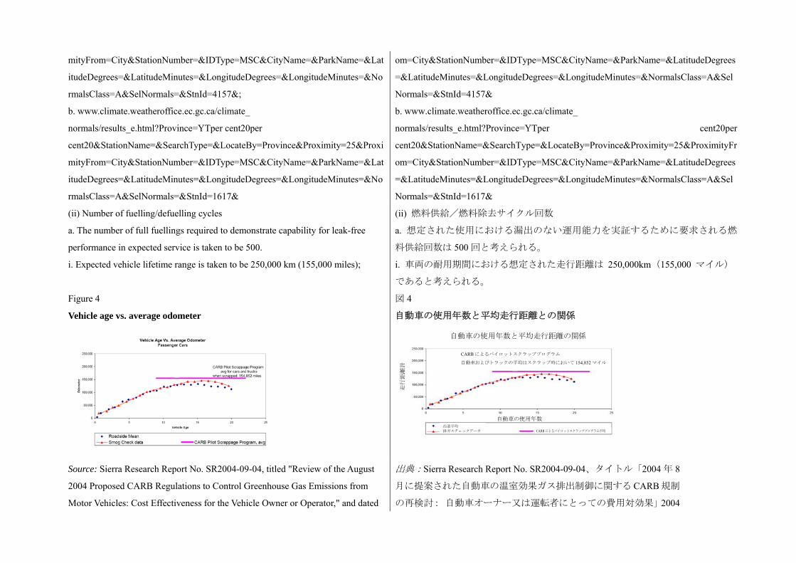
mityFrom=City&StationNumber=&IDType=MSC&CityName=&ParkName=&Lat
itudeDegrees=&LatitudeMinutes=&LongitudeDegrees=&LongitudeMinutes=&No
rmalsClass=A&SelNormals=&StnId=4157&;
b. www.climate.weatheroffice.ec.gc.ca/climate_
normals/results_e.html?Province=YTper cent20per
cent20&StationName=&SearchType=&LocateBy=Province&Proximity=25&Proxi
mityFrom=City&StationNumber=&IDType=MSC&CityName=&ParkName=&Lat
itudeDegrees=&LatitudeMinutes=&LongitudeDegrees=&LongitudeMinutes=&No
rmalsClass=A&SelNormals=&StnId=1617&
om=City&StationNumber=&IDType=MSC&CityName=&ParkName=&LatitudeDegrees
=&LatitudeMinutes=&LongitudeDegrees=&LongitudeMinutes=&NormalsClass=A&Sel
Normals=&StnId=4157&
b. www.climate.weatheroffice.ec.gc.ca/climate_
normals/results_e.html?Province=YTper cent20per
cent20&StationName=&SearchType=&LocateBy=Province&Proximity=25&ProximityFr
om=City&StationNumber=&IDType=MSC&CityName=&ParkName=&LatitudeDegrees
=&LatitudeMinutes=&LongitudeDegrees=&LongitudeMinutes=&NormalsClass=A&Sel
Normals=&StnId=1617&
(ii) Number of fuelling/defuelling cycles
a. The number of full fuellings required to demonstrate capability for leak-free
performance in expected service is taken to be 500.
i. Expected vehicle lifetime range is taken to be 250,000 km (155,000 miles);
(ii) 燃料供給/燃料除去サイクル回数
a. 想定された使用における漏出のない運用能力を実証するために要求される燃
料供給回数は 500 回と考えられる。
i. 車両の耐用期間における想定された走行距離は 250,000km(155,000 マイル)
であると考えられる。
Figure 4
Vehicle age vs. average odometer
図 4
自動車の使用年数と平均走行距離との関係
Source: Sierra Research Report No. SR2004-09-04, titled "Review of the August
2004 Proposed CARB Regulations to Control Greenhouse Gas Emissions from
Motor Vehicles: Cost Effectiveness for the Vehicle Owner or Operator," and dated
出典:Sierra Research Report No. SR2004-09-04、タイトル「2004 年 8
月に提案された自動車の温室効果ガス排出制御に関する CARB 規制
の再検討: 自動車オーナー又は運転者にとっての費用対効果」2004
自動車の使用年数と平均走行距離の関係
走行距離計
CARB によるパイロットスクラッププログラム
自動車およびトラックの平均はスクラップ時において 154,852 マイル
自動車の使用年数沿道平均 排ガスチェックデータ CARB によるパイロットスクラッププログラム平均
22 September 2004. 年 9 月 22 日付
ii. Expected vehicle range per full fuelling is taken to be greater than or equal to
500 km (300 miles) (based on 2006-2007 market data of high volume passenger
vehicle manufacturers in Europe, Japan and North America);
iii. 500 cycles = 250,000 miles/500 miles-per-cycle ~ 150,000 miles/300
miles-per-cycle;
iv. Some vehicles may have shorter driving ranges per full fuelling, and may
achieve more than 500 full fuellings if no partial fuellings occur in the vehicle life.
Demonstrated capability to perform without leak in 500 full fuellings is intended to
establish fundamental suitability for on-road service leakage is subject to
secondary mitigation by detection and vehicle shut-down before safety risk
develops;
ii. 1 回の全充填に対する車両の想定走行距離は、500km(300 マイル)以上と
考えられる。(欧州、日本、北米の乗用車量産メーカーに関する 2006-2007 年
の市場データに基づく。)
iii. 500 サイクル = 250,000 マイル/1 サイクルあたり 500 マイル ~ 150,000 マ
イル/1 サイクルあたり 300 マイル
iv. 一部の車両は 1 回の全充填あたりの走行距離が短く、部分的な燃料供給を
行わなければ、耐用期間中に 500 回以上の全充填を行うものがある。漏出を生
じることなく 500 回の全充填を行う能力を実証することは、基本的な路上使用
に適することを証明するものであり、漏出は検出により二次的保護が作動し、
安全上のリスクが増大する前に車両が停止する。
v. Since the stress of full fuellings exceeds the stress of partial fuellings, the design
verification test provides a significant margin of additional robustness for
demonstration of leak-free fuelling/de-fuelling capability.
v. 全充填による応力が部分充填による応力を上回ることから設計確認試験で
は、漏出のない燃料供給/燃料除去能力を実証するためロバスト性強化のため
に大幅なマージンが設定されている。
b. Qualification requirement of 500 pneumatic pressure cycles is conservative
when considering failure experience:
i. On-road experience: 70 MPa hydrogen storage systems have developed leaks in
o-ring sealings during brief (less than 50 full fuellings) on-road service of
demonstration prototype vehicles;
b. 500 回の気圧サイクルの認定要件は、故障経験を考慮すると控えめな設定であ
る。
i. 路上経験:70MPa の水素貯蔵システムにおいて、実演用試作車の短期間の路
上使用中(全充填 50 回未満)に O-リングシール部に漏出が発生した。
ii. On-road experience: 70 MPa hydrogen storage systems have developed
temporary (subsequently resealing) leaks during brief (less than 50 full fuellings)
on-road service of demonstration prototype vehicles;
ii. 路上経験:70MPa の水素貯蔵システムにおいて、実演用試作車の短期間の路
上使用中(全充填 50 回未満)に一時的な(後に再密閉された)漏出が発生した。
iii. On-road experience: mechanical failures of CNG vehicle storage associated
with gas intrusion into wrap/liner and interlaminate interfaces have developed after
brief on-road service (less than 50 full fuellings);
iii. 路上経験:CNG 車両の貯蔵システムにおいて、ガスが被覆/ライナーに浸入
する機械的故障が発生し、短期間の路上使用後(全充填 50 回未満)に層間に接
触面が生じた。
iv. On-road experience: failure of CNG vehicle storage due to interior charge iv. 路上経験:CNG 車両の貯蔵システムにおいて、内部に電荷が蓄積し故障が発
build-up and liner damage corona discharge is not a failure mode because static
charge is carried into containers on particulate fuel impurities and ISO 14687-2
(and SAE J2719) fuel requirements limit particulates in hydrogen fuel – also, fuel
cell power systems are not tolerant of particulate impurities and such impurities are
expected to cause vehicles to be out of service if inappropriate fuel is dispensed;
生した。ライナー破損コロナ放電は故障モードではない。これは、静電荷が燃
料に含まれる微粒子状の不純物と共に容器内に入り込むからであり、ISO
14687-2(及び SAE J2719)の燃料に関する要求事項で、水素燃料に含まれる粒
子状物質が制限されている。また、燃料電池の電力システムは、粒子状の不純
物を許容しておらず、不適切な燃料を供給した場合、これらの不純物により車
両が使用できなくなると考えられる。
v. Test experience: mechanical failures of vehicle storage systems associated with
gas intrusion into wrap/liner and interlaminate interfaces develop in ~50 full
fuellings;
v. 試験経験:車両の貯蔵システムにおいて、ガスが被覆/ライナーに浸入する
機械的故障が発生し、全充填 50 回未満で層間に接触面が生じた。
vi. Test experience: 70MPa hydrogen storage systems that passed Natural Gas Vehicle
(NGV2) test requirements have failed during the test conditions of para. 5.1.3. in failure
modes that would be expected to occur in on-road service. The Powertech report
(McDougal, M., "SAE J2579 Validation Testing Program Powertech Final Report",
National Renewable Energy Laboratory Report No. SR-5600-49867
(www.nrel.gov/docs/fy11osti/49867.pdf) cites two failures of systems with containers
that have qualified for service: metal-lined composite container valve leak and
in-container solenoid leak, polymer-lined composite container leak due to liner
failure. The polymer-lined composite container failure by leakage was on a
container that was qualified to American National Standard Association and
Canadian Standards Association (ANSI/CSA) NGV2 modified for hydrogen. The
metal-lined composite failure of the container valve was on a valve qualified to
EIHP rev12b. Report conclusion: "The test sequences in SAE TIR J2579 have
shown that containers with no known failures in service either met the
requirements of the tests, or fail for reasons that are understood and are
representative of future service conditions"
vi. 試験経験:天然ガス車両(NGV2)試験の要件に合格した 70MPa の水素貯蔵
システムが、5.1.3 項の試験条件下で、路上使用でも生じると予測される故障モ
ードで不合格となった。The Powertech report (McDougal, M.著「SAE J2579 確認
試験プログラム Powertech 終報告書」、National Renewable Energy Laboratory
Report No. SR-5600-49867(www.nrel.gov/docs/fy11osti/49867.pdf)において、使用
認定を受けた容器を搭載したシステムに関する 2 種類の故障について言及して
いる。金属で裏打ちされた複合材料容器の弁及び容器内のソレノイドからの漏
出と、ポリマーで裏打ちされた複合材料容器の、ライナー故障による漏出であ
る。ポリマーで裏打ちされた複合材料容器における漏出による故障は、米国国
家規格協会及びカナダ規格協会(ANSI/CSA)により、水素燃料に改造した NGV2
として認定された容器で発生した。金属で裏打ちされた複合材料容器における
容器弁による故障は、EIHP rev12b で認定された弁で発生した。報告書の結論で
は、「SAE TIR J2579 の連続試験により、既知の故障のない容器の使用において、
試験の要件に適合する場合と、あるいは理解された、将来の使用条件の典型と
なる理由により不適合となる場合のいずれかであることが判明した。」として
いる。
(iii) Fuelling conditions
a. SAE J2601 establishes fuelling protocol — 3 minutes is fastest empty-to-full
(iii) 燃料供給条件
a. SAE J2601 では燃料供給プロトコルを規定している。 速の空から全充填まで
fuelling (comparable to typical gasoline fuelling; existing in installed state-of-art
hydrogen fuelling stations); fuel temperature for 70 MPa fast fuelling is ~ -40 °C;
の供給は 3 分である。(一般的なガソリン給油の場合と同等である。 先端の
水素燃料供給ステーションに設置されている。)70MPa 高速燃料供給時の燃料
温度は、-40以上である。
b. Expected maximum thermal shock conditions are for a system equilibrated at an
environmental temperature of ~50 °C subjected to -40 °C fuel, and for a system
equilibrated at -40 °C subjected to indoor private fuelling at approximately
+20 °C;
b. 想定される 大熱衝撃条件は、50以下の周囲温度で平衡状態のシステムの
場合は-40の燃料供給、-40で平衡状態のシステムの場合は約+20の屋
内個別燃料供給である。
c. Fuelling stresses are interspersed with parking stresses. c. 燃料供給応力は駐車応力に組み込まれている。
(c) Leak-free parking at full fill (para. 5.1.3.3.)
(i) Leak and permeation are risk factors for fire hazards for parking in confined
spaces such as garages;
(c) 全充填状態での漏出のない駐車(5.1.3.3 項)
(i) 漏出及び透過は、車庫などの密閉空間に駐車した場合の火災原因のリスク要
因である。
(ii) The leak/permeation limit is characterized by the many possible combinations
of vehicle and garages, and the associated test conditions. The leak/permeation
limit is defined to restrict the hydrogen concentration from reaching 25 per cent
Lower Flammability Limit (LFL) by volume with worst credible conditions of a
tight, very hot (55°C) garage having a low air exchange rate (0.03 volumetric air
exchanges per hour). The conservative 25 per cent LFL limit is conventionally
adopted to accommodate concentration inhomogeneities. Data for hydrogen
dispersion behaviour, garage and vehicle scenarios, including garage sizes, air
exchange rates and temperatures, and the calculation methodology are found in the
following reference prepared as part of the EC Network of Excellence (NoE)
HySafe: P. Adams, A. Bengaouer, B. Cariteau, V. Molkov, A.G. Venetsanos,
"Allowable hydrogen permeation rate from road vehicles", Int. Journal of
Hydrogen Energy, volume 36, issue 3, 2011 pp 2742-2749;
(ii) 漏出/透過限界値は、車両と車庫の組み合わせ及び関連する試験条件により
異なる。漏出/透過限界値は、空気の交換率が低く(1 時間あたり 0.03 容積換
気)、狭く高温(55)の車庫内という想定される 悪の条件下で、水素濃度
が下限可燃限界(LFL)の 25 容量%に達することを制限している。LFL 制限値
25%という控えめな値は、濃度の不均一性に対応するために従来から採用され
てきたものである。水素の分散挙動のデータ、車庫の規模、空気交換率及び温
度を含めた車庫と車両の状況、及び計算方法については、EC Network of
Excellence (NoE) HySafe の一環として作成された以下の文書に記載されている。
P. Adams、A. Bengaouer、B. Cariteau、V. Molkov、A.G. Venetsanos 著、「路上車
両からの水素透過許容量」、Int. Journal of Hydrogen Energy、第 36 巻、第 3 号、
2011 年、2742-2749 ページ。
(iii) The resulting discharge limit measured at 55°C and 115 per cent NWP (full fill
at 55°C) following specified pneumatic pressure cycling of the storage system is
scalable depending on the vehicle size around a nominal value of 150 mL/min for a
(iii) 規定された気圧サイクルを貯蔵システムに実施した後、55及び NWP の
115%(55で全充填)で測定した結果得られた排出量の限界値は、車庫サイズ
30.4m3で車両サイズにより公称値 150mL/分付近で拡張可能である。スケール要
garage size of 30.4 m3. The scaling factor, R =
(Vwidth+1)*(Vheight+0.05)*(Vlength+1)/ 30.4, accommodates alternative
garage/vehicle combinations to those used in the derivation of the rate, and
accommodates small vehicles that could be parked in smaller garages. These
vehicle-level permeation requirements are consistent with the proposals developed
by the EU (NoE) HySafe (see above reference). The permeation values measured
for individual storage container systems used in a vehicle would total to less than
the vehicle limit;
素、R = (Vwidth+1)*(Vheight+0.05)*(Vlength+1)/ 30.4、は計算で使用したものとは
別の車庫/車両の組み合わせ、及び小規模な車庫に駐車することができる小型車
に対応している。これらの車両レベルの透過要件は、EU (NoE) HySafe(上記を
参照)の策定した案と一致する。1 台の車両に搭載された各貯蔵容器システムに
ついて測定した透過値の合計は、当該車両の制限値未満となる。
(iv) For ease of compliance testing, however, the discharge requirement has been
specified in terms of storage system permeation instead of vehicle-level (iii)
permeation as a means of compliance is consistent with the proposals developed by
the EU NoE HySafe. In this case, the permeation limit measured at 55°C and 115
per cent NWP is 46 mL/h/L-water-capacity of the storage system. If the total water
capacity of the vehicle storage system is less greater than 330 L and the garage size
is no smaller than 50 m3, then the 46 m L/h/L-water-capacity requirement results in
a steady-state hydrogen concentration of no more than 1 per cent. (An upper limit
per storage system of 46 mL/h/L (per container volume capacity) x 330L (system
volume capacity) / 60min/hr = 253 mL/min per storage system, which comparable
to that derived from the alternative approach 150 mL/min x 50/30.4 = 247 mL/min
(scaling factor R=1.645), which results in a 1 per cent concentration). This
permeation specification has been adopted under the assumption that storage
capacity ~330L is not expected for the vehicles within the scope of this gtr, so
garages less than 50m3 can be accommodated;
(iv) しかしながら適合試験を容易にするため、排出に関する要求事項は車両レベ
ル(iii)の透過ではなく、貯蔵システム単位で規定されてきており、この適合手段
は、EU NoE HySafe が策定した案と一致している。この場合、55、NWP の 115%
で測定した透過限界は、車両の貯蔵システムの総水容量 46mL/h/L である。車両
の貯蔵システムの総水容量が約 330L で、車庫の規模は 50m3以上であれば、
46mL/h/Lの水容量要件により、安定状態の水素濃度は 1%以下となる。(46mL/h/L
の各貯蔵システムの上限 (容器の容積容量で) x 330L (システムの容積容量) /
60min/hr = 253mL/min 貯蔵システム毎、これは代替手法で求められる値と同じ
であり、150mL/min x 50/30.4 = 247mL/min (スケール要素 R=1.645)、濃度は 1%
となる。)この透過に関する規定は、本 gtr の適用範囲内の車両で 330L 以下の
貯蔵容量はないと考えられるという想定に基づき採用された。従って、50m3未
満の車庫に対応できる。
(v) The maximum pressure of a fully filled container at 55°C is 115 per cent NWP
(equivalent state of charge to 125 per cent NWP at 85°C and 100 per cent NWP at
15°C);
(v) 55、NWP の 115%で全充填された容器の 大圧力(85で NWP の 125%、
15で NWP の 100%と同等の充填状態)
(vi) A localized leak test is to be conducted to ensure that external leakage cannot (vi) 材質の弱体化を招き、それにより密閉状態が失われるような火炎に外部漏出

sustain a flame that could weaken materials and subsequently cause loss of
containment. Per Technical Report 2008-01-0726 ("Flame Quenching Limits of
Hydrogen Leaks"), the lowest flow of H2 that can support a flame is 0.028 mg/sec
per from a typical compression fitting and the lowest leak possible from a
miniature burner configuration is 0.005 mg/sec. Since the miniature burner
configuration is considered a conservative "worst case", the maximum leakage
criterion is selected as 0.005 mg/sec;
が曝されないことを保証するため、局所的な漏出試験を実施する。Technical
Report 2008-01-0726(「水素漏れの火炎クエンチング限界」)によると、火炎を
起こす H2の 低量は、一般的な圧縮フィッティングからの流出の場合は
0.028mg/秒であり、小型バーナー配列から漏出する可能性のある 低量は
0.005mg/秒である。小型バーナー配列の数値は控えめな「 悪のケース」であり、
大漏出基準は 0.005mg/秒と選定されている。
(vii) Parking provides opportunity for hydrogen saturation of interlaminate layers,
wrap/liner interface, liner materials, junctures, o-rings, and joinings – fuelling
stresses are applied with and without exposure to hydrogen saturation. Hydrogen
saturation is marked by permeation reaching steady-state rate;
(vii) 駐車時には、水素が交互層、被覆/ライナー接触面、ライナー材料、結合
部、O-リング、及び接合部の水素飽和が起こる。水素飽和への暴露がある場合、
ない場合ともに燃料供給応力が加わる。水素飽和は、透過が定常状態速度に達
した状態である。
(viii) By requiring qualification under the worst credible case conditions of raised
temperature, pressure cycling and equilibration with hydrogen, the permeation
verification removes uncertainty about permeation/temperature dependence, and
long term deterioration with time and usage.
(viii) 温度、圧力サイクル、水素平衡を増大した想定可能な 悪の条件下での認
定を要求することで、透過確認により透過/温度依存及び時間経過と使用によ
る長期的な劣化に関する不確実性を取り除くことができる。
(d) Residual proof pressure (para. 5.1.3.4.)
(i) Fuelling station over-pressurization is constrained by fuelling station
requirements to pressurize at less than 150 per cent NWP. (This requirement for
fuelling stations shall be established within local codes/regulations for fuelling
stations.);
(ii) Laboratory data on static stress rupture was used to define equivalent
probability of stress rupture of composite strands. It showed the rupture probability
after 4 minutes at 180 per cent NWP to be equivalent for after 10 hours at 150 per
cent NWP in the worst case (SAE Technical Report 2009-01-0012). Fuelling
stations are expected to protect against over-pressure over 150 per cent NWP;
(iii) Field data on the frequency of failures of high pressure fuelling stations
involving activation of pressure relief controls is not available. The small number
(d) 残留耐圧(5.1.3.4 項)
(i) 燃料供給ステーションにおける過圧は、燃料供給ステーションに関する要求
事項により NWP の 150%未満に制限されている。(燃料供給ステーションに関
するこの制限は、燃料供給ステーションに関する地域の条例及び/又は法令に
て規定するものとする。
(ii) 複合材料ストランドの応力破裂の同等の確率を規定するため、静圧破裂に関
する実験室データを使用した。それによると、NWP の 180%で 4 分後に複合材
料ストランドの破裂が発生する確率と 悪のケース(SAE Technical Report
2009-01-0012)として NWP の 150%で 10 時間後に発生する確率が同等であるこ
とが判明した。燃料供給ステーションは、NWP の 150%までの過圧保護を講じ
ることが求められる。
(iii) 高圧燃料供給ステーションにおける、圧力除去装置の作動を伴う故障の発
of 70 MPa fuelling stations currently available does not support robust statistics. 生頻度に関するフィールドデータはない。現在利用可能な少数の 70MPa 燃料供
給ステーションでは、ロバスト統計の裏付けにはならない。
(e) Residual strength burst (para. 5.1.3.5.)
Requirement for less than 20 per cent decline in burst pressure after lifetime
service is designed to ensure stability of structural components responsible for
rupture resistance; it is linked (in SAE Technical Report 2009-01-0012) to
assurance that requirement has allowance for 10 per cent manufacturing variability
in assurance of greater than 25 years of rupture resistance at 100 per cent NWP in
para. 5.1.2.5.
As regards container liners, it is suggested that attention should be paid for
deterioration of container liners. The container liner could be inspected after burst.
Then, the liner and liner/end boss interface could be inspected for evidence of any
deterioration, such as fatigue cracking, disbonding of plastics, deterioration of seal,
or damage from electrostatic discharge. The record of findings should be shared
with the container manufacturer.
It is expected that regulatory agencies and manufacturers will monitor the
condition and performance of storage systems during service life as practical and
appropriate to continually verify that para. 5.1.3. performance requirements capture
on-road requirements. This advisory is meant to encourage manufacturers and
regulatory agencies to collect additional data.
(e) 残留強度破裂(5.1.3.5 項)
耐用期間にわたる使用後の破裂圧減少が 20%未満という要求事項は、破裂耐性
を担う構造部品の安定性を保証するためのものである。これは、5.1.2.5 項によ
る NWP の 100%で 25 年超の破裂耐久性を保証するため、製造時のばらつきに
より要求事項に±10%の余裕を持たせていることと関連(SAE Technical Report
2009-01-0012 において)している。
容器のライナーに関しては、その劣化に注意を払うことが求められる。破裂後
に容器のライナーを検査する。続いてライナー及びライナー/エンドボス接触
面を検査し、疲労クラック、プラスチック剥離、シール劣化、あるいは静電放
電による破損などの劣化がないか確認する。所見の記録は容器製造者と共有す
る。
規制当局及び製造者は、耐用期間中における貯蔵システムの状態及び性能を可
能な限り、かつ 5.1.3 項の性能要件が路上要件に対応していることを継続的に確
認できるように監視することが求められる。この勧告は、製造者及び規制当局
にさらなるデータ収集を促すことを目的としている。
(d) Rationale for paragraphs 5.1.4. and 6.2.5. verification test for
service-terminating performance in fire
(d) 5.1.4 項及び 6.2.5 項の火災時におけるサービス停止性能の確認試験の論拠
64. Verification of performance under service-terminating conditions is designed to
prevent rupture under conditions so severe that hydrogen containment cannot be
maintained. Fire is the only service-terminating condition accounted for in design
qualification.
64. サービス停止状態における性能確認は、水素の密閉状態が保てなくなるほど
過酷な条件下での破裂を防止するために策定された。設計認定においては、火災
のみをサービス停止条件として挙げている。
65. A comprehensive examination of CNG container in-service failures during the 65. CNG 容器の使用中に発生した故障を、過去 10 年間にわたり包括的に調査し
past decade (SAE Technical Paper 2011-01-0251 (Scheffler, McClory et al.,
"Establishing Localized Fire Test Methods and Progressing Safety Standards for
FCVs and Hydrogen Vehicles")) showed that the majority of fire incidents occurred
on storage systems that did not utilize properly designed pressure relief devices
(PRDs), and the remainder resulted when PRDs did not respond to protect the
container due to the lack of adequate heat exposure on the PRDs even though the
localized fire was able to degrade the container wall and eventually cause the
storage container to burst. The localized fire exposure has not been addressed in
previous regulations or industry standards. The fire test method in para. 6.2.5.
addresses both localized and engulfing fires.
た結果(SAE Technical Paper 2011-01-0251(Scheffler, McClory 他著、「燃料電池
車と水素自動車のための局所的火災試験方法の確立と安全性規格化の推進」))、
大半の火災事例が設計が不適切な圧力除去装置(PRD)を使った貯蔵システムで
発生していることが判明した。その他は、PRD が充分な熱に暴露されず、適切に
作動しなかったことから容器を保護できず、局所的な火災により容器の壁面が劣
化し、 終的に貯蔵容器が破裂したことが判明した。局所的火災への暴露は、過
去の規制あるいは業界基準で扱われていなかった。6.2.5 項の火災試験方法では、
局所的火災と全面的火災の両方を扱っている。
66. The fire test conditions of para. 6.2.5. were based on vehicle-level tests by the
Japanese Automobile Research Institute (JARI) and US manufacturers. A summary
of data is found in paper SAE Technical Paper 2011-01-0251. Key findings are as
follows:
66. 6.2.5 項の試験条件は、日本自動車研究所(JARI)及び米国のメーカーによる
車両レベルの試験に基づいている。データの概要は、SAE Technical Paper
2011-01-0251 に掲載されている。主な所見は以下の通り。
(a) About 40 per cent of the vehicle laboratory fires investigated resulted in
conditions that could be categorized as a localized fire since the data indicates that
a composite compressed gas container could have been locally degraded before
conventional PRDs on end bosses (away from the local fire exposure) would have
activated. (Note: A temperature of 300°C was selected as the temperature where the
localized fire condition could start as thermal gravimetric analysis (TGA) indicates
that container materials begin to degrade rapidly at this temperature);
(a) 調査を行った実験室における車両火災の約 40%は、局所的火災と分類できる
状態のものであった。データによると、エンドボス(局所的火災の発火点から離
れた場所にある)に取り付けられた従来型の PRD が作動する前に、複合材料製
の圧縮ガス容器が局所的に劣化していた可能性があることがわかった。(注:局
所的火災が発生する可能性のある温度として 300が選定された理由は、熱重量
分析(TGA)によりこの温度で容器材料が急速に劣化し始めることが判明してい
るからである。)
(b) While vehicle laboratory fires often lasted 30-60 minutes, the period of
localized fire degradation on the storage containers lasted less than 10 minutes;
(c) The average of the maximum temperature during the localized fire period was
less than 570°C with peak temperatures reaching approximately between 600°C
and 880°C in some cases;
(b) 実験室における車両火災は 30-60 分で終息したケースが多かったが、貯蔵容
器の局所的火災による劣化は 10 分未満で終息した。
(c) 局所的火災発生中の 大温度の平均値は、570未満であった。この時、一部
のケースではピーク温度が約 600-880に達した。
(d) The rise in peak temperature near the end of the localized fire period often (d) 局所的火災の終わり間近にピーク温度が上昇した場合、全面的火災へ移行す
signaled the transition to an engulfing fire condition. る兆候である場合が多かった。
67. Based upon the above findings, the temperature profile in para. 6.2.5. was
adopted. The selection of 600°C as the minimum temperature for the localized fire
hold period ensures that the average temperature and time of localized fire test
exposure are consistent with test data. Thermocouples located 25 mm ± 10mm
from the outside surface of the test article are used to control the heat input and
confirm that the required temperature profile is met. In order to improve the
response and controllability of the fire during testing (as well as reproducibility of
results), the use of Liquefied Petroleum Gas (LPG) and wind guards are specified.
Experience indicates the controllability of the LPG fire will be approximately
±100°C in outdoor situations, producing peak temperatures that also agree
favourably with test results.
67. 上記の所見に基づき、6.2.5 項の温度プロファイルが採用された。局所的火災
の持続期間中における 低温度として 600を選定したことにより、平均温度及
び局所的火災試験の暴露時間を試験データと一致させた。試験試料の外面から
25mm±10mm の位置に設置した熱電対を使って加熱量を制御し、要求された温度
プロファイルが実現されていることを確認した。試験中の火炎の反応及び制御性
(及び結果の再現性)を改善するため、液化石油ガス(LPG)及び風よけの使用
が規定された。LPG 火炎の制御性は屋外では約±100であり、ピーク温度が試験
結果と一致することが経験によりわかった。
68. The proposed localized fire test set-up is based on preliminary work done by
Transport Canada and the National Highway Traffic Safety Administration
(NHTSA) in the United States of America, but the approach was expanded to allow
the storage system to be qualified by either a generic installation test or a specific
vehicle installation test. Differences between the two methods are as follows:
68. 局所的火災試験の設定案は、Transport Canada 及び米国の幹線道路交通安全局
(NHTSA)が行った準備作業に基づいているが、貯蔵システムを一般的取り付
け試験又は特定車両取り付け試験のいずれかで認定することができるよう手段
の幅を広げた。2 つの手法の違いは以下の通り。
(a) The generic (non-vehicle specific) allows the localized fire test to apply to more
than one vehicle but the mitigation devices (such as shields) need to be
permanently affixed to the storage system and shall protect the entire system, not
just the area exposed to the localized fire. The size for the generic localized fire test
was selected to be 250 mm ± 50 mm longitudinally with a width covering the
diameter of the container;
(a) 一般的(特定車両でない)試験では、局所的火災試験を複数の車両に実施す
ることができるが、緩和装置(保護など)は貯蔵システムに恒久的に取り付け、
局所的火災に暴露される部分だけでなくシステム全体を保護することが要求さ
れる。一般的局所的火災試験の規模は、縦方向に 250mm±50mm、幅は容器の直
径以上の長さを選定すること。
(b) The specific vehicle installation localized fire test would be customized to align
with the actual fire exposure area and would include protective features from the
vehicle. If the vehicle manufacturer elects to use the specific vehicle test approach,
the direction and size of the localized fire exposure is adjusted to account for
(b) 特定車両取り付け局所的火災試験は、実際の火炎暴露部分と一致するようカ
スタマイズすることができる。また、車両の保護機能を含めてもよい。車両メ
ーカーが特定車両試験を選定する場合、隣接する金属薄板の照明用穴、配線及
び配管用貫通部、火炎経路で溶解した材料により生じた穴を含めた開口部など
vehicle features such as openings in adjacent sheet metal for lightening holes and
pass-throughs for wires and piping or holes formed by the melting of materials in
the path of the fire. If such openings or holes are small, the size of the localized is
reduced from the generic size to create a more challenging (and realistic) test.
の車両特性を考慮して局所的火災の暴露方向及び規模を調整する。これらの穴
や開口部が小さい場合、局所的火災の規模を一般的な規模から縮小して、より
厳しい(かつ現実的な)試験を設定する。
(e) Rationale for paragraphs 5.1.5 and 6.2.6 qualification tests for
storage-system hydrogen-flow closures
(e) 5.1.5 項及び 6.2.6 項の貯蔵システムにおける水素遮断に関する認定試験の論
拠
69. The reliability and durability of hydrogen-flow closures is essential for the
integrity of the full storage system. The closures are partially qualified by their
function in the system-level performance tests (paragraph 5.1.). In addition, these
closures are qualified individually not only to assure exceptional reliability for
these moving parts, but also to enable equivalent components to be exchanged in a
storage system without re-qualifying the entire storage system. Closures that isolate
high pressure hydrogen from the remainder of the fuel system and the environment
include:
69. 水素流遮断装置の信頼性及び耐久性は、貯蔵システム全体の完全性にとって
不可欠なものである。遮断装置は、システムレベルの性能試験(5.1 項)におい
てその機能を部分的に認定する。さらに、これらの遮断装置はこれらの可動部
の優れた信頼性を保証するためだけでなく、貯蔵システムにおいて、システム
全体を再認定することなく同等部品への交換を可能にするため、個別に認定さ
れる。高圧水素とその他の燃料システムを分離する遮断装置には以下のものが
含まれる。
(a) Thermally activated pressure relief device (TPRD). A TPRD opens and remains
open when the system is exposed to fire;
(b) Check valve. A check valve prevents reverse flow in the vehicle fuelling line,
e.g. a non-return valve. Equivalent to a non-return valve;
(c) Shut-off valve. An automatic shut-off valve between the storage container and
the vehicle fuel delivery system defaults to the closed position when unpowered.
(a) 熱動作型圧力除去装置(TPRD)。システムが火炎に暴露された時、TPRD
が開き、その状態を維持する。
(b) チェック弁。逆止弁は車両の燃料供給管路における逆流を防止する。例、逆
止め弁。逆止め弁と同じ。
(c) 遮断弁。貯蔵容器と車両の燃料輸送システム間の自動遮断弁は、電力が遮断
されると閉状態に戻る。
70. Test procedures for qualification of hydrogen-flow closures within the
hydrogen storage system were developed by the International Organization of
Vehicle Manufacturers (OICA) as outgrowths of discussions within CSA
workgroups for TPRD1:2009 and HGV3.1 (as yet unpublished), and reports to
those CSA workgroups testing sponsored by US-DOE and performed at Powertech
Laboratories to verify closure test procedures under discussion within CSA.
Differences between the requirements established herein and the CSA documents
70. 水素貯蔵システムにおける水素流遮断装置の認定試験手順は、TPRD1:2009
及び HGV3.1(未発表)に関する CSA 作業グループ内での討議、及び CSA で討
議中の密閉試験手順を検証するため、US-DOE が主催し、Powertech Laboratories
にて CSA 作業グループが実施した試験の報告書から派生して、世界自動車工業
会(OICA)により策定された。本書及び CSA 文書で規定する要求事項の違いは、
主に適用範囲の違いによるものである。CSA の要求事項は、酷使用途を含めた
すべての路上用途を網羅している。
derive primarily from differences in scope: CSA requirements encompass all on
road applications including heavy duty applications.
(i) Rationale for TPRD qualification requirements (i) TPRD 認定要件の論拠
71. The qualification requirements verify that the device, once activated, will fully
vent the contents of the fuel container even at the end of the service life when the
device has been exposed to fuelling/defuelling pressure and temperature changes
and environmental exposures. The adequacy of flow rate for a given application is
verified by the hydrogen storage system fire test requirements (para. 5.1.4.).
71. この認定要件では、装置が燃料供給/燃料除去時の圧力及び温度変化及び各
種環境に曝された場合、耐用期間末期であっても装置が作動することにより燃
料容器内の内容物がすべて排出されることを確認する。特定用途における流量
の妥当性については、水素貯蔵システムの燃焼試験要件(5.1.4 項)で確認する。
(ii) Rationale for check valve qualification requirements (ii) 逆止弁認定要件の論拠
72. These requirements are not intended to prevent the design and construction of
components (e.g. components having multiple functions) that are not specifically
prescribed in this standard, provided that such alternatives have been considered in
testing the components. In considering alternative designs or construction, the
materials or methods used shall be evaluated by the testing facility to ensure
equivalent performance and reasonable concepts of safety to that prescribed by this
standard. In that case, the number of samples and order of applicable tests shall be
mutually agreed upon by the manufacturer and the testing agency. Unless otherwise
specified, all tests shall be conducted using hydrogen gas that complies with SAE
J2719 (Information report on the development of a hydrogen quality guideline for
fuel cell vehicles), or ISO 14687-2 (Hydrogen fuel-product specification). The total
number of operational cycles shall be 11,000 (fuelling cycles) for the check valve
and 50,000 (duty cycles) for the automatic shut-off valve.
72. この要求事項は、本規格にて特に規定されていない構成部品(例、複数の機
能を持つ構成部品)について、代替の設計及び施工がその構成部品の試験にお
いて検討されているならば、これらを妨げるものではない。代替の設計又は施
工の検討にあたっては、使用する材料及び方法について試験機関による評価を
受け、本規格の規定と同等の性能及び妥当な安全概念を保証するものとする。
その場合、試料数及び適用試験について、メーカーと試験機関の間で相互に合
意する。別途規定がない限り、試験は SAE J2719(燃料電池自動車向け水素の品
質ガイドライン策定に関する情報報告書)あるいは ISO 14687-2(水素燃料-製
品仕様)に適合した水素ガスを使って実施する。作動サイクルの合計回数は、
逆止弁は 11,000 回(燃料供給サイクル)、自動遮断弁は 50,000 回(負荷サイク
ル)とする。
73. Fuel flow shut-off by an automatic shut-off valve mounted on a compressed
hydrogen storage container shall be fail-safe. The term "fail safe" refers to a device
that reverts to a safe mode or a safe complete shutdown for all reasonable failure
modes.
73. 圧縮水素貯蔵容器に取り付けられた自動遮断弁による燃料流の遮断は、フェ
イルセーフであること。「フェイルセーフ」とは、すべての相応な故障モード
に対して、セーフモードあるいは安全な完全遮断に復帰する装置を指す。
74. The electrical tests for the automatic shut-off valve mounted on the compressed 74. 圧縮水素貯蔵容器に取り付けられた自動遮断弁の電気試験(6.2.6.2.7 項)は、
hydrogen storage containers (para. 6.2.6.2.7.) provide assurance of performance
with: (i) over temperature caused by an overvoltage condition, and (ii) potential
failure of the insulation between the component’s power conductor and the
component casing. The purpose of the pre-cooled hydrogen exposure test (para.
6.2.6.2.10.) is to verify that all components in the flow path from the receptacle to
the container that are exposed to precooled hydrogen during fuelling can continue
to operate safely.
(i)過電圧状態に起因する過剰な温度上昇、及び(ii)構成部品の電源導体と構成部
品のケーシング間の絶縁の潜在的欠陥における性能を保証するものである。予
冷水素暴露試験(6.2.6.2.10 項)は、供給口から容器までの流路におけるすべて
の構成部品が、燃料供給時に予冷水素に曝されても安全に動作し続けられるこ
とを確認するものである。
(f) Rationale for paragraph 5.1.6. labelling
75. The purpose of minimum labelling on the hydrogen storage containers is
three-fold: (i) to document the date when the system should be removed from
service, (ii) to record information needed to trace manufacturing conditions in
event of on-road failure, and (iii) to document NWP to ensure installation is
consistent with the vehicle fuel system and fuelling interface. Contracting Parties
may specify additional labelling requirements. Since the number of pressure cycles
used in qualification under para. 5.1.1.2. may vary between Contracting Parties,
that number shall be marked on each container.
(f) 5.1.6 項ラベル表示の論拠
75. 水素貯蔵容器に取り付ける 低限のラベル表示の目的は以下の 3 つである。
(i)システムの使用を停止する日付を記載する。(ii)路上故障が発生した場合に製
造条件を追跡するために必要な情報を記録する。(iii)取り付けが車両の燃料シス
テム及び燃料供給接合部と一致していることを保証するため NWP を記録する。
締約国はラベル表示に関する追加の要求事項を規定してもよい。締約国により
5.1.1.2 項で規定した認定試験で使用する圧力サイクルの回数が異なるため、こ
の回数を各容器に記載すること。
2. Vehicle fuel system requirements and safety needs 2. 車両の燃料システム要件及び安全ニーズ
(a) In-Use Requirements
(i) Fuelling receptacle rationale for paragraphs 5.2.1.1.
76. The vehicle fuelling receptacle should be designed to ensure that the fuelling
pressure is appropriate for the vehicle fuel storage system. Examples of receptacle
designs can be found in ISO 17268, SAE J2600 and SAE J2799. A label shall be
affixed close to the fuelling receptacle to inform the fueler/driver/owner of the type
of fuel (liquid or gaseous hydrogen), NWP and date for removal of storage
containers from service. Contracting parties may specify additional labelling
requirements.
(ii) Rationale for paragraph 5.2.1.2. overpressure protection for the low pressure
(a) 使用における要求事項
(i) 5.2.1.1 項の燃料供給口の論拠
76. 車両の燃料供給口は、燃料供給圧が車両の燃料貯蔵システムに適するように
設計されていること。供給口の設計例は、ISO 17268、SAE J2600、及び SAE J2799
に記載されている。燃料供給者/運転者/所有者に燃料の種類(液体水素又は水
素ガス)、NWP、及び貯蔵容器の使用停止日を知らせるラベルを燃料供給口の近
くに表示すること。締約国はラベル表示に関する追加の要求事項を規定してもよ
い。
(ii) 5.2.1.2 項の低圧システムにおける過圧保護の論拠
system
77. The hydrogen delivery system downstream of a pressure regulator is to be
protected against overpressure due to the possible failure of the pressure regulator.
77. 圧力調整器の下流にある水素輸送システムには、圧力調整器の故障による過
圧に対する保護を施すこと。
(iii) Rationale for paragraph 5.2.1.3. hydrogen discharge system
a. Rationale for paragraph 5.2.1.3.1. pressure relief systems
(iii) 5.2.1.3 項の水素排出システムの論拠
a. 5.2.1.3.1 項の圧力除去システムの論拠
78. The vent line of storage system discharge systems (TPRDs and PRDs) should
be protected by a cap to prevent blockage by intrusion of objects such as dirt,
stones, and freezing water.
78. 貯蔵システムにおける排出システム(TPRD 及び PRD)の排出管路は、ごみ、
石、水の凍結などの異物の浸入により閉塞することのないよう、キャップを取り
付けて保護すること。
b. Rationale for paragraph 5.2.1.3.2. vehicle exhaust systems
79. In order to ensure that the exhaust discharge from the vehicle is non-hazardous,
a performance-based tests is designed to demonstrate that the discharge is
non-ignitable. The 3 second rolling-average accommodates extremely short,
non-hazardous transients up to 8 per cent without ignition. Tests of flowing
discharges have shown that flame propagation from the ignition source readily
occurs above 10 per cent hydrogen, but does not propagate below 8 per cent
hydrogen (SAE Technical Report 2007-01-437, Corfu et al., "Development of
Safety Criteria for Potentially Flammable Discharges from Hydrogen Fuel Cell
Vehicles"). By limiting the hydrogen content of any instantaneous peak to 8 per
cent, the hazard to people near the point of discharge is controlled even if an
ignition source is present. The time period of the rolling-average is determined to
ensure that the space around the vehicle remains non-hazardous as the hydrogen
from exhaust diffuses into the surroundings; this is the case of an idling vehicle in a
closed garage. In order to readily gain acceptance for this situation by building
officials and safety experts, it should be recognized that government/municipal
building codes and internationally-recognized standards such as International
Electrotechnical Commission (IEC) 60079 require that the space be less than 25
per cent LFL (or 1 per cent hydrogen) by volume. The time limit for the
b. 5.2.1.3.2 項の車両排気システムの論拠
79. 車両からの排気が無害であることを保証するため、排気が非引火性であるこ
とを実証する性能ベースの試験を策定する。3 秒の移動平均は、8%以下の発火を
伴わない非常に短時間で無害な瞬時排出に対応している。排気試験により、点火
源からの火炎伝播は水素濃度 10%以上で容易に発生するが、8%未満では伝播し
ないことが判明した(SAE Technical Report 2007-01-437、Corfu 他著、「水素燃料
電池自動車からの可燃性排気に対する安全性基準の策定」)。瞬時的なピーク水
素濃度を 8%に抑えることで、たとえ点火源がある場合でも、排出点付近にいる
人に害が及ぶことを防ぐ。移動平均の期間は、排気管からの水素が周囲に拡散し
ても車両周囲の空間が無害な状態を保つことを保証するよう設定された。閉め切
った車庫内で車両をアイドリングさせた場合がこれにあてはまる。この状況に対
する建築主事及び安全専門家による賛同を容易に得るため、政府/地方自治体の
建築基準法及び国際電気標準会議(IEC)60079 などの国際的に認められた基準
では、空間が LFL25 容積%(あるいは水素 1 容積%)未満を要求していることを
認識する必要がある。移動平均の制限時間は、100kW の燃料スタックへの供給量
と同等の非常に高い水素排出量を想定して策定された。次に、この水素排出が乗
用車(4.6m×2.6m×2.6m)の占める公称間隙を 25%LFL まで埋めるまでの時間を
計算した。結果として得られた制限時間は、「移動平均」8 秒と余裕を持って見
積もった。これにより、本文書で使用する移動平均 3 秒という値が適切であり、
rolling-average was determined by assuming an extremely high hydrogen
discharge rate that is equivalent to the input to a 100 kW fuel cell stack. The time
was then calculated for this hydrogen discharge to fill the nominal space occupied
by a passenger vehicle (4.6m x 2.6m x 2.6m) to 25 per cent LFL. The resultant
time limit was conservatively estimated to be 8 seconds for a "rolling average,"
demonstrating that the 3-second rolling average used in this document is
appropriate and accommodates variations in garage and engine size. The standard
ISO instrumentation requirement is a factor of 6-10 less than the measured value.
Therefore, during the test procedure according to para. 6.1.4., the 3-second rolling
average requires a sensor response (90 per cent of reading) and recording rate of
less than 300 milliseconds.
多様な規模の車庫及びエンジンに対応していることを実証している。ISO 規格の
計装要求事項は、測定値よりも 6-10 倍低くなっている。従って、6.1.4 項の試験
手順を実施する間、移動平均 3 秒はセンサー応答(測定の 90%)及び 300 ミリ秒
未満の記録速度が必要である。
(iv). Rationale for paragraph 5.2.1.4. protection against flammable conditions:
80. Single Failure Conditions. Dangerous situations can occur if unintended
leakage of hydrogen reaches flammable concentrations.
(iv). 5.2.1.4 項の引火に対する保護の論拠
80. 単一故障条件。予期せぬ水素漏れが引火濃度に達すると危険な状態を招く可
能性がある。
(a) Any single failure downstream of the main hydrogen shut off valve shall not
result in any level of hydrogen concentration in air anywhere in the passenger
compartment;
(a) 一次水素遮断弁の下流で発生した単一故障により、客室内のいずれの場所で
もいかなる濃度の水素も生じないこと。
(b) Protection against the occurrence of hydrogen in air in the enclosed or
semi-enclosed spaces within the vehicle that contain unprotected ignition sources is
important.
(b) 保護されていない点火源を持つ車両内の密閉空間あるいは半密閉空間におけ
る空気中の水素発生に対する保護が重要である。
(i) Vehicles may achieve this objective by design (for example, where spaces are
vented to prevent increasing hydrogen concentrations);
(i) この要件は、車両設計により満たすことができる。(例えば、空間を換気し、
水素濃度の増加を防ぐ。)
(ii) The vehicle achieves this objective by detection of hydrogen concentrations in
air of 2 per cent ± 1.0 per cent or greater, then the warning shall be provided. If the
hydrogen concentration exceeds
3 per cent ± 1.0 per cent by volume in air in the enclosed or semi-enclosed spaces
of the vehicle, the main shutoff valve shall be closed to isolate the storage system.
(ii) 車両は、空気中の 2±1.0%以上の水素濃度を検出することでこの要件を満た
し、それに対して警告を発する。車両の密閉空間又は半密閉空間における空気中
の水素濃度が 3±1.0 容積%を超える場合、一次遮断弁が閉じて貯蔵システムを分
離すること。

(v) Rationale for paragraph 5.2.1.5. fuel leakage
81. Detectable leakage is not permitted.
(vi) Rationale for paragraph 5.2.1.6. visual signal/warning system
(v) 5.2.1.5 項の燃料漏出の論拠
81. 検出可能な漏出は発生してはならない。
(vi) 5.2.1.6 項の可視信号/警報システムの論拠
82. A visual signal/warning system is to alert the driver when hydrogen leakage
results in concentration levels at or above 4 per cent by volume within the
passenger compartment, luggage compartment, and spaces with unprotected
ignition sources within the vehicle. The visual signal/warning system should also
alert the driver in case of a malfunction of the hydrogen detection system.
Furthermore, the system shall be able to respond to either scenario and instantly
warn the driver. The shut-off signal shall be inside the occupant compartment in
front of and in clear view of the driver. There is no data available to suggest that
the warning function of the signal would be diminished if it is only visual. In case
of a detection system failure, the signal warning light should be yellow. In case of
the emergency shut-off of the valve, the signal warning light should be red.
82. 可視信号/警報システムは、水素漏出により客室内、荷物室内、及び車両内
保護されていない点火源のある空間における水素濃度レベルが4容積%以上に達
したことを運転者に警告するものである。可視信号/警報システムは、水素検知
システムが誤動作した場合にも運転手に知らせるものとする。さらにこのシステ
ムは、いずれの状況にも反応し、即時に運転者に警告するものとする。遮断信号
は、客室内の運転者の前のはっきりと見える位置にあること。信号が視覚的なも
ののみの場合、信号の警告機能が低下することを示唆するデータはない。検知シ
ステムが故障した場合の信号の警告灯は黄色であること。弁の緊急遮断を行う場
合、信号の警告灯は赤色であること。
(vii) Lower flammability limit (LFL) (vii) 下限可燃限界(LFL)
83. (Background for paragraph 3.34.): Lowest concentration of fuel in which a gas
mixture is flammable. National and international standard bodies (such as National
Fire Protection Association (NFPA) and IEC) recognize 4 per cent hydrogen by
volume in air as the LFL (US Department of Interior, Bureau of Mines Bulletin
503, 1952; Houf and Schefer, "Predicting Radiative Heat Fluxes and Flammability
Envelopes from Unintended Releases of Hydrogen," International Journal of
Hydrogen Energy 31, pp 136-151, 2007; NASA RD-WSTF-0001, 1988). The LFL,
which depends on the temperature, pressure and presence of dilution gases, has
been assessed using specific test methods (e.g. American Society for Testing
(ASTM) E681-04). While the LFL value of 4 per cent is appropriate for evaluating
flammability in general surroundings of vehicles or inside passenger
compartments, this criterion may be overly restrictive for flowing gas situations
83. (3.34 項の背景):混合気体が可燃となる燃料の 低濃度。(全国防火協会
(NFPA)及び IEC などの)国内及び国際規格団体は、空気中の 4 容積%の水素
濃度を LFL としている。(米国内務省、鉱山局公報 503、1952 年;Houf 及び Schefer
著、「意図しない水素放出による放射熱流束と可燃性範囲の予測」、International
Journal of Hydrogen Energy 31、136-151 ページ、2007 年;NASA RD-WSTF-0001、
1988 年)温度、圧力、及び希釈ガスの存在に依存する LFL は、特殊な試験方法
で算定されてきた。(例、全米材料試験協会(ASTM)E681-04)4%の LFL 値は、
車両の一般的な周囲環境、あるいは客室内における可燃性を評価する場合には適
切であるが、この基準は、多くの場合、発火に 4%濃度の水素が必要となる流動
ガスの状況には非常に厳しいものである。特定の場所にある点火源により漏出ガ
スプルームに引火するか否かは、流動状態及び点火の種類による。静穏な室温の
混合気体中の水素濃度が 4%の場合、燃焼は上方向にのみ伝播する。混合気体中
where ignition requires more than 4 per cent hydrogen in many cases. Whether an
ignition source at a given location can ignite the leaking gas plume depends on the
flow conditions and the type of ignition. At 4 per cent hydrogen in a stagnant
room-temperature mixture, combustion can only propagate in the upward direction.
At approximately 8 to 10 per cent hydrogen in the mixture, combustion can also be
propagated in the downward and horizontal directions and the mixture is readily
combustible regardless of location of ignition source. Coward, H.F. et al, "Limits of
flammability of gases and vapors," Bureau of Mines Bulletin 503; 1952, USA;
Benz, F.J. et al, "Ignition and thermal hazards of selected aerospace fluids",
RD-WSTF-0001, NASA Johnson Space Center White Sands Test Facility, Las
Cruces, NM, USA, October 1988; Houf, W.G. et al, "Predicting radiative heat
fluxes and flammability envelopes from unintended releases of hydrogen,",
International Journal of Hydrogen Energy, 32 pp136-141, 2007
の水素濃度が約 8-10%になると、燃焼は下方向及び水平方向へも伝播し、点火源
の位置にかかわらず混合気体は容易に燃焼する。Coward, H.F.他著、「気体及び
蒸気の可燃限界」、鉱山局公報 503;1952 年、アメリカ合衆国;Benz, F.J.他著、
「特定航空宇宙流体の発火及び熱的危険性」、RD-WSTF-0001、NASA ジョンソ
ンスペースセンターホワイトサンズ試験施設、アメリカ合衆国ニューメキシコ州
ラスクルーセス、1988 年 10 月;Houf, W.G.他著、「意図しない水素放出による
放射熱流束と可燃性範囲の予測」、International Journal of Hydrogen Energy、32、
136-141 ページ、2007 年
(viii) Recommended features for design of a hydrogen fuel system
84. As any performance-based technical regulation cannot include testing
requirements for every possible scenario, this section is to provide manufacturers a
list of items that they should consider during the design of hydrogen fuelling
systems with the intention to reduce hydrogen leaks and provide a safe product:
(viii) 水素燃料システムの設計における推奨特性
84. 性能ベースの技術規制において起こり得るすべての状況に関する試験要件を
網羅することはできない。そこで本項では、製造者が水素燃料供給システムの設
計において、水素漏出を低減し安全な製品を提供するために考慮すべき項目を挙
げる。
(a) The hydrogen fuel system should function in a safe and proper manner and be
designed to minimize the potential for hydrogen leaks, (e.g. minimize line
connections to the extent possible);
(a) 水素燃料システムは、安全かつ適正に動作するものとし、水素漏出の可能性
を極力抑える設計を行う。(例、可能な限り管路接続を少なくする。)
(b) The hydrogen fuel system should reliably withstand the chemical, electrical,
mechanical and thermal service conditions that may be found during normal
vehicle operation;
(b) 水素燃料システムは、通常の車両運用において曝される化学物質、電気的、
機械的、及び温度の使用条件に確実に耐えるものとする。
(c) The materials used should be compatible with gaseous or liquid hydrogen, as
appropriate;
(c) 使用する材料は、水素ガス又は液体水素のそれぞれに適したものとする。
(d) The hydrogen fuel system should be installed such that it is protected against (d) 水素燃料システムは、通常の車両運用において生じる損傷から保護されるよ
damage under normal operating conditions;
(e) Rigid fuel lines should be secured such that they shall not be subjected to
critical vibration or other stresses;
(f) The hydrogen fuel system should protect against excess flow in the event of a
failure downstream;
うに取り付けるものとする。
(e) 固定燃料管路は、臨界振動あるいはその他の応力を受けないように固定する
ものとする。
(f) 水素燃料システムは、下流で故障が発生した場合に過流から保護するものと
する。
(g) No component of the hydrogen fuel system, including any protective materials
that form part of such components, should project beyond the outline of the vehicle
or protective structure.
(g) 水素燃料システムの構成部品は、これらの構成部品の一部を構成する保護材
も含めていずれも、車両又は保護構造物の外形よりも突出しないものとする。
(b) Post crash requirements
(i) Rationale for paragraph 5.2.2.1. post-crash test leakage limit
85. Allowable post-crash leakage in Federal Motor Vehicle Safety Standard
(FMVSS) 301 (for the United States of America) and Regulation Nos. 94 and 95
are within 6 per cent of each other for the 60 minute period after the crash. Since
the values are quite similar, the value in Regulation No. 94 of 30g/min was selected
as a basis for the calculations to establish the post-crash allowable hydrogen
leakage for this gtr.
(b) 衝突後の要求事項
(i) 5.2.2.1 項の衝突後の試験における漏出限界の論拠
85. 連邦政府自動車安全基準(FMVSS)301(アメリカ合衆国向け)及び規制
No. 94、95 における衝突後 60 分間の許容漏出量の差は 6%しかない。値が非常
に近いことから、規制 No.94 の数値 30g/分を本 gtr における衝突後の許容水素漏
出量算出の基準値として採用した。
86. The criterion for post-crash hydrogen leakage is based on allowing an
equivalent release of combustion energy as permitted by gasoline vehicles. Using a
lower heating value of 120 MJ/kg for hydrogen and 42.7 MJ/kg for gasoline based
on the US DOE Transportation Data Book, the equivalent allowable leakage of
hydrogen can be determined as follows:
For vehicles with either compressed hydrogen storage systems or liquefied
hydrogen storage systems. The total allowable loss of hydrogen is therefore 642g
for the 60 minute period following the crash.
86. 衝突後の水素漏出量の基準は、ガソリン車で放出を許容された燃焼エネルギ
ーと同等量の放出を認めること基づいている。US DOE Transportation Data Book
に基づく水素の低位発熱量 120 MJ/kg 及びガソリンの 42.7 MJ/kg を使い、以下の
式により同等の許容水素漏出量が算出できる。
(式中の語句)
ガソリン漏出量 30g/分 水素漏出量 10.7g/分
圧縮水素貯蔵システムあるいは液体水素貯蔵システムを搭載した車両の場合。
従って衝突後の 60 分間における許容水素減少量の合計は、642g となる。
leakage hydrogen g/min 10.7 MJ/kg 120MJ/kg 42.7 xleakage gasolineg/min 30 WH == leakage hydrogen g/min 10.7
MJ/kg 120MJ/kg 42.7 xleakage gasolineg/min 30 WH ==
87. The allowable hydrogen flow leakage can also be expressed in volumetric
terms at normal temperature (0°C) and pressure as follows:
for vehicles with either compressed or liquid hydrogen storage.
88. As confirmation of the hydrogen leak rate, JARI conducted ignition tests of
hydrogen leaks ranging from 131 NL/min up to 1000 NL/min under a vehicle and
inside the engine compartment. Results showed that, while a loud noise can be
expected from ignition of the hydrogen, the sound pressure level and heat flux
were not enough (even at a 1000 NL/min leak rate) to damage the under floor area
of the vehicle, release the vehicle hood, or injure a person standing 1 m from the
vehicle (SAE Technical Paper 2007-01-0428 "Diffusion and Ignition Behavior on
the Assumption of Hydrogen Leakage from a Hydrogen-Fuelled Vehicle"). The
container shall remain attached to the vehicle at a minimum of one attachment
point.
87. 圧縮水素貯蔵システム又は液体水素貯蔵システムを搭載した車両の許容水
素漏出量は、常温(0)及び常圧における体積項で以下のように表すこともで
きる。
88. 水素漏出量を確認する方法として、JARI は車両下及びエンジン室内におけ
る 131NL/分から 1000NL/分までの漏出水素の点火試験を実施した。その結果、
水素に着火した際の大音響は予想されるものの、(1000NL/分の漏出量でも)音
圧レベル及び熱流束による車両床下の損傷、車両フードの解放、車両から 1m の
距離に立つ人の受傷には至らないことが判明した。(SAE Technical Paper
2007-01-0428「水素燃料自動車からの水素漏出を想定した拡散挙動と着火挙動」)
容器は、少なくとも 1 か所以上で車両に固定された状態を維持すること。
(ii) Rationale for paragraph 5.2.2.2. post-crash concentration limit in enclosed
spaces
(ii) 5.2.2.2 項の密閉空間における衝突後の濃度限度の論拠
89. This test requirement has been established to ensure that hydrogen does not
accumulate in the passenger, luggage, or cargo compartments that could potentially
pose a post-crash hazard. The criteria was conservatively set to 4 per cent hydrogen
by volume as the value represents the lowest possible level at which combustion
can occur (and the combustion is extremely weak at this value). Since the test is
conducted in parallel with the post-crash leak test and therefore will extend for at
least 60 minutes, there is no need to provide margin on the criteria to manage
dilution zones as there is sufficient time for the hydrogen to diffuse throughout the
compartment.
89. 当該試験要件は、衝突後の危険をもたらす可能性のある水素の蓄積が客室、
荷物室、貨物室内で発生しないことを保証するために策定された。基準値は余
裕を持たせて水素濃度 4%容積とした。これは、燃焼が生じる可能性がある も
低い値(さらにこの値での燃焼は非常に弱い)である。衝突後の漏出試験と並
行して当該試験を実施することから、期間は 60 分以上に拡張する。これにより、
室内全体に水素が拡散する時間が充分に確保されることから、混合領域に対応
するために基準にマージンを設ける必要はない。
(iii) Rationale for paragraph 5.2.2.3. container displacement. (iii) 5.2.2.3 項の容器の移動の論拠
118NL/min NL/mol 22.41 x g/mol (1.00794) 2
g/min 10.7 V H ==118NL/min NL/mol 22.41 x
g/mol (1.00794) 2g/min 10.7 V H ==
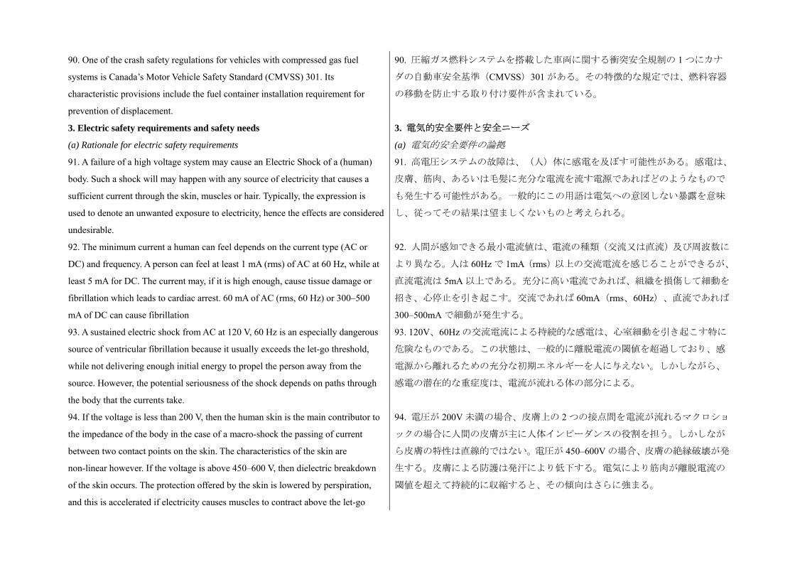
90. One of the crash safety regulations for vehicles with compressed gas fuel
systems is Canada’s Motor Vehicle Safety Standard (CMVSS) 301. Its
characteristic provisions include the fuel container installation requirement for
prevention of displacement.
90. 圧縮ガス燃料システムを搭載した車両に関する衝突安全規制の 1 つにカナ
ダの自動車安全基準(CMVSS)301 がある。その特徴的な規定では、燃料容器
の移動を防止する取り付け要件が含まれている。
3. Electric safety requirements and safety needs
(a) Rationale for electric safety requirements
91. A failure of a high voltage system may cause an Electric Shock of a (human)
body. Such a shock will may happen with any source of electricity that causes a
sufficient current through the skin, muscles or hair. Typically, the expression is
used to denote an unwanted exposure to electricity, hence the effects are considered
undesirable.
3. 電気的安全要件と安全ニーズ
(a) 電気的安全要件の論拠
91. 高電圧システムの故障は、(人)体に感電を及ぼす可能性がある。感電は、
皮膚、筋肉、あるいは毛髪に充分な電流を流す電源であればどのようなもので
も発生する可能性がある。一般的にこの用語は電気への意図しない暴露を意味
し、従ってその結果は望ましくないものと考えられる。
92. The minimum current a human can feel depends on the current type (AC or
DC) and frequency. A person can feel at least 1 mA (rms) of AC at 60 Hz, while at
least 5 mA for DC. The current may, if it is high enough, cause tissue damage or
fibrillation which leads to cardiac arrest. 60 mA of AC (rms, 60 Hz) or 300–500
mA of DC can cause fibrillation
92. 人間が感知できる 小電流値は、電流の種類(交流又は直流)及び周波数に
より異なる。人は 60Hz で 1mA(rms)以上の交流電流を感じることができるが、
直流電流は 5mA 以上である。充分に高い電流であれば、組織を損傷して細動を
招き、心停止を引き起こす。交流であれば 60mA(rms、60Hz)、直流であれば
300–500mA で細動が発生する。
93. A sustained electric shock from AC at 120 V, 60 Hz is an especially dangerous
source of ventricular fibrillation because it usually exceeds the let-go threshold,
while not delivering enough initial energy to propel the person away from the
source. However, the potential seriousness of the shock depends on paths through
the body that the currents take.
93. 120V、60Hz の交流電流による持続的な感電は、心室細動を引き起こす特に
危険なものである。この状態は、一般的に離脱電流の閾値を超過しており、感
電源から離れるための充分な初期エネルギーを人に与えない。しかしながら、
感電の潜在的な重症度は、電流が流れる体の部分による。
94. If the voltage is less than 200 V, then the human skin is the main contributor to
the impedance of the body in the case of a macro-shock the passing of current
between two contact points on the skin. The characteristics of the skin are
non-linear however. If the voltage is above 450–600 V, then dielectric breakdown
of the skin occurs. The protection offered by the skin is lowered by perspiration,
and this is accelerated if electricity causes muscles to contract above the let-go
94. 電圧が 200V 未満の場合、皮膚上の 2 つの接点間を電流が流れるマクロショ
ックの場合に人間の皮膚が主に人体インピーダンスの役割を担う。しかしなが
ら皮膚の特性は直線的ではない。電圧が 450–600V の場合、皮膚の絶縁破壊が発
生する。皮膚による防護は発汗により低下する。電気により筋肉が離脱電流の
閾値を超えて持続的に収縮すると、その傾向はさらに強まる。
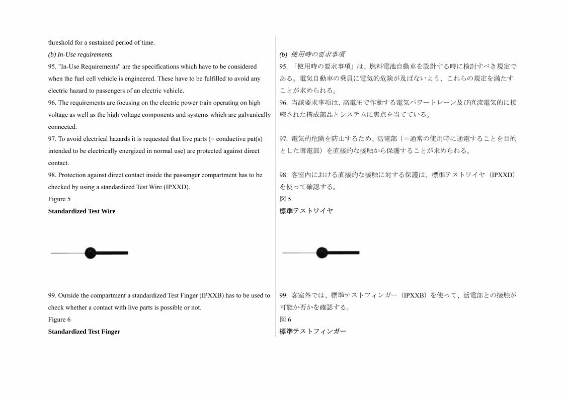
threshold for a sustained period of time.
(b) In-Use requirements (b) 使用時の要求事項
95. "In-Use Requirements" are the specifications which have to be considered
when the fuel cell vehicle is engineered. These have to be fulfilled to avoid any
electric hazard to passengers of an electric vehicle.
95. 「使用時の要求事項」は、燃料電池自動車を設計する時に検討すべき規定で
ある。電気自動車の乗員に電気的危険が及ばないよう、これらの規定を満たす
ことが求められる。
96. The requirements are focusing on the electric power train operating on high
voltage as well as the high voltage components and systems which are galvanically
connected.
96. 当該要求事項は、高電圧で作動する電気パワートレーン及び直流電気的に接
続された構成部品とシステムに焦点を当てている。
97. To avoid electrical hazards it is requested that live parts (= conductive pat(s)
intended to be electrically energized in normal use) are protected against direct
contact.
97. 電気的危険を防止するため、活電部(=通常の使用時に通電することを目的
とした導電部)を直接的な接触から保護することが求められる。
98. Protection against direct contact inside the passenger compartment has to be
checked by using a standardized Test Wire (IPXXD).
98. 客室内における直接的な接触に対する保護は、標準テストワイヤ(IPXXD)
を使って確認する。
Figure 5
Standardized Test Wire
図 5
標準テストワイヤ
99. Outside the compartment a standardized Test Finger (IPXXB) has to be used to
check whether a contact with live parts is possible or not.
99. 客室外では、標準テストフィンガー(IPXXB)を使って、活電部との接触が
可能か否かを確認する。
Figure 6
Standardized Test Finger
図 6
標準テストフィンガー

100. Furthermore exposed conductive parts (= parts which can be touched with the
standardized Test Finger and becomes electrically energized under isolation failure
conditions) have also to be protected against indirect contact. This means that e.g.
conductive barriers or enclosures have to be galvanically connected securely to the
electrical chassis.
100. さらに、露出した導電部(=標準テストフィンガーで触れることのできる部
分で、絶縁不良が発生した状態で通電する部分)も間接的な接触から保護しなけ
ればならない。これは例えば、導電体のバリヤあるいはエンクロージャを電気的
シャシーに直流電気的に確実に接続することを意味する。
101. Beside protection of direct and indirect contact isolation resistance is required
for AC (Alternating Current) and DC (Direct Current) systems. Isolation resistance
measured against the electrical chassis is a physical dimension describing which
maximum current flowing through the human body is not dangerous.
101. 直接的及び間接的接触に対する保護の他にも、AC(交流電流)及び DC(直
流電流)システムには絶縁抵抗が必要である。電気的シャシーに対して測定した
絶縁抵抗は、人体内を流れるどの 大電流が危険でないかを表す物理的寸法であ
る。
102. While DC systems are less harmful to the humans (see para. 5.4.1.) 100
Ω/Volt are required. AC systems have to fulfill 500 Ω/Volt. For the DC systems an
on-board isolation resistance monitoring system is required which warns the driver
when the resistance is below 100 Ω/Volt.
102. DC システムの方が人体に害が少ない(5.4.1 項を参照)が、100Ω/V が必要
である。ACシステムは 500Ω/V が必要である。DCシステムには、抵抗値が 100Ω/V
未満になったことを運転者に警告する車載絶縁抵抗監視装置が必要である。
103. The isolation resistance requirements of 100 Ω/Volt for DC or 500 Ω/Volt for
AC allow maximum body currents of 10 mA and 2 mA respectively.
103. DC システムの絶縁抵抗 100Ω/V 及び AC システムの 500Ω/V の要件により、
身体電流はそれぞれ 大 10mA と 2mA が許容される。
(c) Post-crash requirements
104. Post-Crash requirements are the specifications which have to be fulfilled by
the vehicles after the impact. They do not describe the way how the impact has to
be conducted. This is the responsibility of each Contracting Party. The
requirements have to be fulfilled to avoid any electric hazard to passengers of the
vehicle.
(c) 衝突後の要求事項
104. 衝突後の要求事項は、衝撃後の車両が満たすべき項目を規定したものであ
る。衝撃を加える方法については規定していない。これについては各締約国が規
定するものとする。車両の乗員に電気的危険が及ばないよう、これらの要求事項
を満たすものとする。

105. The requirements are focusing on the electric power train operating on high
voltage as well as the high voltage components and systems which are galvanically
connected.
105. 当該要求事項は、高電圧で作動する電気パワートレーン及び直流電気的に接
続された構成部品とシステムに焦点を当てている
106. After the impact of the vehicle the following three measures demonstrate that
the systems are safe. It means that the remaining "electricity level" of the high
voltage systems are no longer dangerous to the passengers of the vehicle.
106. 車両に衝撃が加えられた後、以下の 3 つの方法でシステムの安全性を実証す
る。これは、高電圧システムの残留「電気レベル」が車両の乗員にとって危険で
なくなることを意味する。
(a) Absence of high Voltage
After the impact the voltage is equal or less than 30 VAC or 60 VDC
(b) Isolation Resistance
Isolation resistance measured against the electrical chassis is a physical dimension
describing which maximum current is not dangerous to the human being.
After the impact for AC systems measured against the electrical chassis the
minimum isolation resistance has to be 500 Ω/Volt and for DC systems 100 Ω/Volt.
The isolation resistance requirements of 100 Ω/Volt for DC or 500 Ω/Volt for AC
allow maximum body currents of 10 mA and 2 mA respectively.
(a) 高電圧の消失
衝撃後の電圧が 30VAC 又は 60VDC 以下である。
(b) 絶縁抵抗
電気的シャシーに対して測定した絶縁抵抗は、人体内を流れるどの 大電流が危
険でないかを表す物理的寸法である。
衝撃後、電気的シャシーに対して測定した 小絶縁抵抗は、AC システムは
500Ω/V、DC システムは 100Ω/V であること。
DC システムの絶縁抵抗 100Ω/V 及び AC システムの 500Ω/V の要件により、身体
電流はそれぞれ 大 10mA と 2mA が許容される。
(c) Physical protection
After the impact it should not be possible to touch live parts after the crash, tested
with the standardized Test Finger. Furthermore protection against indirect contact
has also been fulfilled.
By decision of the Contracting Parties of the 1998 Agreement a fourth measure is
allowed
(c) 物理的保護
衝撃後、活電部に触れることができないことを標準テストフィンガーで試験して
確認する。さらに、間接的接触に対する保護要件も満たしていること。
1998 年の協定の締約国の判断により、4 つ目の方法も許容される。
(d) Low Energy
After the impact the energy of the system has to be below 2.0 Joules.
(d) 低エネルギー
衝撃後、システムのエネルギーが 2.0 ジュール未満であること。
F. Rationale for storage and fuel system test procedures F. 貯蔵及び燃料システムの試験手順の論拠
107. Test procedures in para. 6. replicate on-road conditions for performance
requirements specified in para. 5. Most test procedures derive from test procedures
107. 6 項の試験手順は、5 項で規定した性能要件のために路上条件を模したもの
である。試験手順の多くは、旧来の国内規定及び/又は業界基準の規定に基づ

specified in historical national regulations and/or industry standards. いている。
1. Rationale for storage and fuel system integrity tests
(a) Rationale for paragraph 6.1.1. test procedure for post-crash leak test
procedure for compressed hydrogen storage systems
1. 貯蔵及び燃料システムの完全性に関する試験の論拠
(a) 6.1.1 項の圧縮水素貯蔵システムにおける衝突後の漏出試験手順の論拠
108. The post-crash leak test is organized as follows:
6.1.1.1. Test procedure when the test gas is hydrogen
6.1.1.2. Test procedure when the test gas is helium
108. 衝突後の漏出試験は以下の通り構成される。
6.1.1.1. 試験気体が水素である場合の試験手順
6.1.1.2. 試験気体がヘリウムである場合の試験手順
109. The loss of fuel represents the allowable release for the entire compressed
hydrogen storage system on the vehicle. The post-crash release can be determined
by measuring the pressure loss of the compressed storage system over a time
period of at least 60 minutes after the crash and then calculating the release rate of
hydrogen based on the measured pressure loss and the time period using the
equation of state of the compressed gas in the storage system. (See the SAE
Technical Paper 2010-01-0133, "Development of the Methodology for FCV
Post-crash fuel leakage testing incorporated into SAE J2578. In the case of
multiple hydrogen storage containers that are isolated from each other after crash,
it may be necessary to measure hydrogen loss individually (using the approach in
para. 5.2.2.1.) and then sum the individual values to determine the total release of
hydrogen gas from the storage system.
109. 燃料の減少は、車両の圧縮水素貯蔵システム全体の許容放出量を表してい
る。衝突後の放出量は、衝突後の少なくとも 60 分間における圧縮貯蔵システムの
圧力低下量を測定し、続いて貯蔵システムの圧縮ガスの状態を表す等式を使って、
測定した圧力低下量及び時間に基づいて水素の放出量を計算することで求められ
る。(SAE Technical Paper 2010-01-0133、「SAE J2578 に導入された FCV 衝突後
燃料漏出試験の方法開発」を参照のこと。)複数の互いに分離された水素容器の
場合、衝突後に水素減少量を個別に(5.2.2.1 項の手法を使って)測定し、それら
の値を合算して貯蔵システムからの水素ガス放出量を求める必要がある。
110. The methodology can also be expanded to allow the use of a non-flammable
gas for crash testing. Helium has been selected as it, like hydrogen, has low
molecular weight. In order to determine the ratio of volumetric flows between
helium and hydrogen releases (and thus establish a required relationship between
hydrogen and helium leakage, we assume that leakage from the compressed
hydrogen storage system can be described as choked flow through an orifice where
the orifice area (A) represents the total equivalent leakage area for the post-crash
system. In this case the equation for mass flow is given by:
110. さらに方法を拡大して、衝突試験に非可燃性ガスを使用することもできる。
非可燃性ガスとしてヘリウムガスが選定された。ヘリウムは水素と同様、分子量
が小さい。ヘリウム放出及び水素放出の体積流量比を求めるため、(それにより
水素漏出とヘリウム漏出の必要な関係を求めるため)圧縮水素貯蔵システムから
の漏出量は開口部からのチョーク流れとして表されると想定した。この時、開口
部の面積(A)は衝突後のシステムにおける漏出部の総面積と同じである。この
場合、質量流の等式は以下の通り。
W = C x Cd x A x (ρ x P)1/2
W = C x Cd x A x (ρ x P)1/2
where Cd is the orifice discharge coefficient, A is the orifice area, P are the
upstream (stagnation) fluid density and pressure, and ρ and C are given by
ρ = Ru x T / M
and
C = γ /( (γ + 1)/2) (γ+1)/(γ-1)
where Ru is the universal gas constant and T, M, and γ are the temperature,
molecular weight, and ratio of specific heats (CV/CP) for the particular gas that is
leaking. Since Cd, A, Ru, T, and P are all constant for the situation of determining
the relationship between post-crash helium and hydrogen leakage, the following
equation describes the flow ratio on a mass basis.
WH2 / WHe = CH2 / CHe x (MH2 / MHe) ½
上記の式において Cd は開口部の放出係数、A は開口部の面積、P は上流の(停滞)
流体密度と圧力である。ρ及び C は以下の式で求められる。
ρ = Ru x T / M
及び
C = γ /( (γ + 1)/2) (γ+1)/(γ-1)
上記の式において Ru は一般気体定数、T、M、及び γ は温度、分子量、及び漏出
する特定の気体の比熱比(CV/CP)である。Cd、A、Ru、T 及び P はすべて衝突後
のヘリウム及び水素の漏出量の関係を求めるための定数であることから、下記の
等式は質量ベースの流量比を表している。
WH2 / WHe = CH2 / CHe x (MH2 / MHe) ½
111. Since we can determine the volumetric flow ratio by multiplying the mass
flow ratio by the ratio of molecular weights (M) at constant temperature and
pressure conditions are the same.
VH2 / VHe = CH2 / CHe x (MHe / MH2) 1/2
111. 体積流量比は質量流量比に分子量比(M)を掛けることで求められることか
ら、一定の温度及び圧力の時、条件は同じである。
VH2 / VHe = CH2 / CHe x (MHe / MH2) 1/2
112. Based on the above relationship, it is possible to determine that the ratio of
the volumetric flow (and therefore the ratio gas concentration by volume) between
helium test gas and hydrogen is approximately 75 per cent for the same leak
passages from the storage system. Thus, the post-crash hydrogen leakage can be
determined by
VH2 = VHe / 0.75
where VHe is the post-crash helium leakage (NL/min).
112. 上記の関係に基づき、貯蔵システムからの同一の漏出経路における試験気体
ヘリウムと水素の体積流量比(従ってガス濃度の体積比)を約 75%とすることが
できる。このように、衝突後の水素漏出量は以下のように求められる。
VH2 = VHe / 0.75
上記の式において、VHeは衝突後のヘリウムの漏出量(NL/分)である。
(b) Rationale for paragraph 6.1.2. (Test procedure for post-crash concentration
test in enclosed spaces for vehicles with compressed hydrogen storage systems)
113. The test may be conducted by measuring hydrogen or by measuring the
corresponding depression in oxygen content. Sensors are to be located at
(b) 6.1.2 項(圧縮水素貯蔵システムを搭載した車両の密閉空間における衝突後の
濃度試験手順)の論拠
113. 試験は、水素の測定又は酸素含有量の低下の測定により行ってもよい。セ
ンサーを客室内、荷物室内、及び貨物室内の有意な箇所に設置する。貯蔵シス
significant locations in the passenger, luggage, and cargo compartments. Since the
test is conducted in parallel with the post-crash leak test of the storage system and
therefore will extend for at least 60 minutes, there is no need to provide margin on
the criteria to manage dilution zones as there is sufficient time for the hydrogen to
diffuse throughout the compartment.
テムの衝突後の漏出試験と並行して当該試験を実施することから、期間は 60 分
以上に拡張する。これにより、室内全体に水素が拡散する時間が充分に確保さ
れることから、混合領域に対応するために基準にマージンを設ける必要はない。
114. In the case where the vehicle is not crashed with hydrogen and a leak test is
conducted with compressed helium, it is necessary to define a criteria for the
helium content that is equivalent to 4 per cent hydrogen by volume. Recognizing
that the content of hydrogen or helium in the compartment (by volume) is
proportional to the volumetric flow of the respective releases, it is possible to
determine the allowable helium content by volume, XHe, from the equation
developed in paras. 108 to 112 of the preamble by multiplying the hydrogen
concentration criteria by 0.75. The criteria for helium concentration is therefore as
follows:
XHe = 4 per cent H2 by volume x 0.75 = 3.0 per cent by volume.
The criteria for helium concentration is therefore 3 per cent by volume in the
passenger, luggage, and cargo compartments if the crash test of a vehicle with a
compressed storage system is conducted with compressed helium instead of
compressed hydrogen.
114. 車両において水素を使った衝突試験を実施せず、圧縮ヘリウムを使って漏
出試験を実施する場合、水素の 4 容量%に相当するヘリウム含有量の基準を定
義する必要がある。客室内における水素又はヘリウム含有量(容量で)がそれ
ぞれの放出における体積流量に比例していることから、許容されるヘリウムの
体積含有量 XHeは、前文の 108 から 112 で策定した等式により、水素濃度基準に
0.75 を掛けて求めることができる。従って、ヘリウム濃度の基準は以下の通り。
XHe = 4 容量%H2 x 0.75 = 3.0 容量%
従って、圧縮貯蔵システムを搭載した車両を、圧縮水素の代わりに圧縮ヘリウ
ムを使って衝突試験を行った場合、客室、荷物室、及び貨物室内におけるヘリ
ウム濃度の基準は、3 容量%である。
115. An example of hydrogen concentration measurement locations can be found in
the document "Examples of hydrogen concentration measurement points for
testing" (OICA report to SGS-3 based on Japanese Regulation Attachment 100).
115. 水素濃度測定箇所の例は、「試験における水素濃度測定箇所の例」(日本
の法令附則 100 に基づく、SGS-3 に対する OICA 報告書)に記載されている。
2. Rationale for paragraph 6.2. (Test procedures for compressed hydrogen
storage systems)
2. 6.2 項(圧縮水素貯蔵システムの試験手順)の論拠
116. Most test procedures for hydrogen storage systems derive from test
procedures specified in historical national regulations and/or industry standards.
Key differences are the execution of tests in sequence (as opposed to historical
116. 水素貯蔵システムに関する試験手順の多くは、旧来の国内規定及び/又は
業界基準の規定に基づいている。主な違いは、(旧来の試験では、別個の新し
い容器に対して並行して試験を実施するのに対し、)連続して試験を実施する

execution of tests in parallel, each on a separate new container), and slowing of the
filling rate in burst testing to correspond to in-service fuelling rates. In addition,
hold times at burst pressure test points have been extended to 4 minutes. These
changes are designed to reduce the sensitivity of initial burst measurements to the
fuelling rate and to evaluate capability to sustain pressure. An evaluation of the
sufficiency and stringency of requirements in this gtr document compared to
historical EU requirements is given in Transport Research Laboratory Project
Report RPN1742 "Hydrogen-Powered Vehicles: A Comparison of the European
Legislation and the draft UNECE global technical regulation" by C. Visvikis.
点、及び破裂試験における燃料供給速度を使用時の燃料供給速度に合わせて下
げた点である。また、破裂圧試験における持続時間を 4 分に延長している。こ
れらの変更は、燃料供給速度に対する初期破裂測定の感度を低減し、耐圧能力
を評価することを目的としている。旧来の EU による要求事項と比較した、本
gtr 文書における要求事項の充足性及び強度の評価については、Transport
Research Laboratory Project Report RPN1742、C. Visvikis 著、「水素燃料自動車:
欧州の法規制と UNECE 世界統一基準草案の比較」に記載されている。
117. Requirements for closures of the hydrogen storage system (TPRD, automatic
shut- off valve and check valve) have been developed by CSA (HGV3.1 and
TPRD-1).
117. 水素貯蔵システムにおける遮断装置(TPRD、自動遮断弁及び逆止弁)に関
する要求事項は、CSA(HGV3.1 及び TPRD-1)により策定された。
(a) Evaluations of cycling durability at 50,000 cycles (para. 6.2.6.2.3.) reflect
multiple pressure pulses against check valves during fuelling and multiple
operations of automatic shut-off valves between fuellings;
(a) 50,000 サイクルのサイクリング耐久性(6.2.6.2.3 項)の評価は、燃料供給時
に逆止弁にかかる多数回の圧力パルス及び燃料供給間に自動遮断弁が行う多数
回の作動を反映している。
(b) Vibration tests (para. 6.2.6.2.8.) were designed to scan frequencies from 10 to
40 Hz because several component testing facilities reported that there can be more
than one resonant frequency. The frequency of 17 Hz used historically in
component vibration tests was established through demonstration of one vehicle
traveling over a variety of road surfaces, and it reflects the influence of engine
proximity. However, it is expected that the resonant frequency could change based
upon the component design and mounting provisions, so to ensure the most severe
condition is identified, a sweep to 40 Hz is required;
(b) 振動試験(6.2.6.2.8 項)は、10 から 40Hz までの周波数を検査することを目
的としている。これは、構成部品の試験機関の多くが、共振周波数が複数ある
可能性を報告していることによる。構成部品の振動試験において旧来使われて
きた 17Hz の周波数は、1 台の車両を多様な道路表面で走行させた実証により設
定されたもので、エンジンの近接度の影響を反映している。しかしながら、共
振周波数は、構成部品の設計及び取り付け条件により変わることが期待される。
従って も厳しい条件を確実に特定するため、40Hz までのスイープが必要であ
る。
(c) The temperature sensitivity, Tlife = 9.1 x Tact0.503, specified in the Accelerated
Life Test (para. 6.2.6.1.2.) is based on D. Stephens (Battelle Memorial Institute)
"Rationale for Long-Term Test Temperature for Thermally Activated PRDs.";
(c) 加速寿命試験(6.2.6.1.2 項)で規定した温度感受性 Tlife = 9.1 x Tact0.503 は、
D. Stephens 著、(Battelle Memorial Institute)「熱動作型 PRD の長期試験温度の
論拠」に基づいている。
(d) Results of closure tests are to be recorded by the testing laboratory and made (d) 遮断試験の結果は、試験機関が記録し製造者に提供する。流量試験において

available to the manufacturer. In the flow rate test, the flow rate is recorded as the
lowest measured value of the eight pressure relief devices tested in NL per minute
(0°C and 1 atmosphere) corrected for hydrogen;
は、8 つの圧力除去装置に対して実施した試験で測定された も低い流量を、水
素に補正した 1 分間あたりの NL(0及び 1 気圧)で記録する。
(e) The atmospheric exposure test (para. 6.2.6.2.6.) derives from two historical
tests. The oxygen ageing test was contained in CSA NGV3.1 and harmonized with
ISO CD 12619 Part 2 (hydrogen components) and ISO 15500 Part 2 (CNG
components). The ozone resistance test drew the requirements and test procedure
from Regulation No. 110 requirement for CNG Components, and has been added
to both the hydrogen and CNG components documents at CSA.
(e) 大気暴露試験(6.2.6.2.6 項)は、旧来の試験を基にしている。酸素老化試験
は CSA NGV3.1 に含まれており、ISO CD 12619 パート 2(水素構成部品)及び
ISO 15500 パート 2(CNG 構成部品)に合わせている。オゾン耐性試験における
要求事項及び試験手順は、CNG 構成部品に関する要求事項を定めた規制 No.110
に基づいており、CSA において水素構成部品文書及び CNG 構成部品文書の両方
に追加された。
G. Optional requirements: vehicles with liquefied hydrogen storage systems /
rationale
G. 任意の要求事項:液体水素貯蔵システムを搭載した車両/論拠
118. Since hydrogen fuelled vehicles are in the early stages of development and
commercial deployment, testing and evaluation of test methods to qualify vehicles
for on-road service has been underway in recent years. However, liquefied
hydrogen storage systems (LHSS) have received considerably less evaluation than
have compressed gas storage systems. At the time of the development of this
document, an LHSS vehicle has been proposed by only one manufacturer, and
on-road vehicle experience with LHSS is very limited. The proposed LHSS
requirements in this document have been discussed on a technical basis, and while
they seem reasonable, they have not been validated. Due to this limited experience
with LHSS vehicles, some Contracting Parties have requested more time for testing
and validation. Therefore, the requirements for LHSS have been presented in
section G as optional.
118. 水素燃料自動車の開発は初期の段階にあり、商業展開、試験及び車両が路
上使用に適することを認定する試験方法の評価が近年進行中である。しかしな
がら液体水素貯蔵システム(LHSS)は、圧縮ガス貯蔵システムと比べてかなり
低い評価を受けてきた。本文書の策定時において LHSS 自動車を企画していたの
は 1 つのメーカーのみであり、LHSS 自動車の路上経験は非常に乏しい。本文書
における LHSS に関する要求事項案は、技術ベースで検討された。これらは妥当
であるように見えるがその正当性は確認されていない。LHSS 自動車における経
験が不足していることから、一部の締約国は試験及び検証にさらなる時間を要
求した。このため、LHSS に関する要求事項は、G 項にオプションとして記載さ
れている。
1. Background information for liquefied hydrogen storage systems
(a) Hydrogen gas has a low energy density per unit volume
119. To overcome this disadvantage, the liquefied hydrogen storage system (LHSS)
1. 液体水素貯蔵システムに関する基本的情報
(a) 水素ガスの単位体積あたりのエネルギー密度は低い
119. このデメリットを打開するため、液体水素貯蔵システム
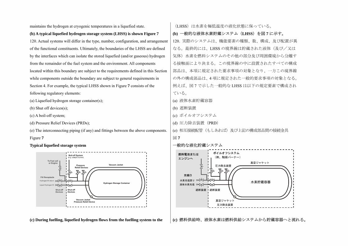
maintains the hydrogen at cryogenic temperatures in a liquefied state. (LHSS)は水素を極低温度の液化状態に保っている。
(b) A typical liquefied hydrogen storage system (LHSS) is shown Figure 7 (b) 一般的な液体水素貯蔵システム(LHSS)を図 7 に示す。
120. Actual systems will differ in the type, number, configuration, and arrangement
of the functional constituents. Ultimately, the boundaries of the LHSS are defined
by the interfaces which can isolate the stored liquefied (and/or gaseous) hydrogen
from the remainder of the fuel system and the environment. All components
located within this boundary are subject to the requirements defined in this Section
while components outside the boundary are subject to general requirements in
Section 4. For example, the typical LHSS shown in Figure 7 consists of the
following regulatory elements:
(a) Liquefied hydrogen storage container(s);
(b) Shut off devices(s);
(c) A boil-off system;
(d) Pressure Relief Devices (PRDs);
(e) The interconnecting piping (if any) and fittings between the above components.
120. 実際のシステムは、機能要素の種類、数、構成、及び配置が異
なる。 終的には、LHSS の境界線は貯蔵された液体(及び/又は
気体)水素を燃料システムのその他の部分及び周囲環境から分離す
る接触面により決まる。この境界線の中に設置されたすべての構成
部品は、本項に規定された要求事項の対象となり、一方この境界線
の外の構成部品は、4 項に規定された一般的要求事項の対象となる。
例えば、図 7 で示した一般的な LHSS は以下の規定要素で構成され
ている。
(a) 液体水素貯蔵容器
(b) 遮断装置
(c) ボイルオフシステム
(d) 圧力除去装置(PRD)
(e) 相互接続配管(もしあれば)及び上記の構成部品間の接続金具
Figure 7
Typical liquefied storage system
図 7
一般的な液化貯蔵システム
(c) During fuelling, liquefied hydrogen flows from the fuelling system to the (c) 燃料供給時、液体水素は燃料供給システムから貯蔵容器へと流れる。
ボイルオフシステム (例、触媒バーナー)
燃料電池または
エンジンへ
充填口
圧力除去装置 真空ジャケット
水素充填戻り 液体水素充填
水素貯蔵容器
遮断装置 遮断装置
真空ジャケット 圧力除去装置
storage container(s)
121. Hydrogen gas from the LHSS returns to the filling station during the fill
process so that the liquefied hydrogen can flow into liquefied hydrogen storage
container(s) without over pressurizing the system. Two shut-offs are provided on
both the liquefied hydrogen fill and hydrogen fill return line to prevent leakage in
the event of single failures.
121. 燃料供給時、LHSS 内の水素ガスは燃料供給ステーションへと戻され、シス
テムが過圧状態になることなく液体水素が貯蔵容器に流入できるようにする。
液体水素充填管路及び充填戻り管路の両方に遮断装置を 2 つ取り付け、単一故
障発生時の漏出を防止する。
(d) Liquefied hydrogen is stored at cryogenic conditions
122. In order to maintain the hydrogen in the liquid state, the container needs to be
well insulated, including use of a vacuum jacket that surrounds the storage
container. Generally accepted rules or standards (such as those listed in para. 7.)
are advised for use in the proper design of the storage container and the vacuum
jacket.
(d) 液体水素は極低温で貯蔵される。
122. 水素を液状に保つため、真空ジャケットで貯蔵容器を覆うなどして、容器
に充分な断熱を施す。貯蔵容器及び真空ジャケットを適正に設計するため、一
般的に認められた規則及び基準(7 項に記載したものなど)を使用することを勧
める。
(e) During longer parking times of the vehicle, heat transfer will induce a
pressure rise within the hydrogen storage container(s)
123. A boil-off system limits heat leakage induced pressure rise in the hydrogen
storage container(s) to a pressure specified by the manufacturer. Hydrogen that is
vented from the LHSS may be processed or consumed in down-stream systems.
Discharges from the vehicle resulting from over-pressure venting should be
addressed as part of allowable leak/permeation from the overall vehicle.
(e) 車両を長時間駐車した場合、熱伝導により水素貯蔵容器内の圧力が増大す
る。
123. ボイルオフシステムは、熱放散による水素貯蔵容器内の圧力増加を、製造
者が規定した値に制限する。LHSS から排気される水素は、下流のシステムにお
いて処理あるいは消費することができる。過圧排気による車両からの排出は、
車両全体からの許容漏出/透過の一部として扱うこと。
(f) Malfunction
124. In case of malfunction of the boil-off system, vacuum failure, or external fire,
the hydrogen storage container(s) are protected against overpressure by two
independent Pressure Relief Devices (PRDs) and the vacuum jacket(s) is protected
by a vacuum jacket pressure relief device.
(f) 誤動作
124. ボイルオフシステムの故障、真空異常、あるいは外部火災が発生した場合、
水素貯蔵容器を 2 つの独立した圧力除去装置(PRD)で過圧から保護し、真空ジ
ャケットを真空ジャケットの圧力除去装置で保護する。
(g) When hydrogen is released to the propulsion system, it flows from the
LHSS through the shut-off valve that is connected to the hydrogen fuel
delivery system
(g) 水素が推進システムから放出される際、水素燃料輸送システムに接続された
遮断弁を通って LHSS から放出される。
125. In the event that a fault is detected in the propulsion system or fuelling
receptacle, vehicle safety systems usually require the container shut-off valve to
isolate the hydrogen from the down-stream systems and the environment.
125. 推進システムあるいは燃料供給口の異常が検知された場合、一般的に車両
の安全システムは、容器の遮断弁に下流システム及び周囲環境から水素を分離
させる。
2. Rationale for liquefied hydrogen storage system design qualification
requirements of para 7.2.
2. 7.2 項の液体水素貯蔵システムの設計承認に関する要求事項の論拠
126. The containment of the hydrogen within the liquefied hydrogen storage
system is essential to successfully isolating the hydrogen from the surroundings
and down-stream systems. The system-level performance tests in para. 7.2. were
developed to demonstrate a sufficient safety level against rupture of the container
and capability to perform critical functions throughout service including pressure
cycles during normal service, pressure limitation under extreme conditions and
faults, and in fires.
126. 水素をその周囲及び下流のシステムから充分に分離するためには、液体水
素貯蔵システム内に水素を密閉することが も重要である。7.2 項のシステムレ
ベルの性能試験は、容器の破裂に対する充分な安全レベル、及び全耐用期間に
わたり、通常使用における圧力サイクル、過酷な条件下、故障時、及び火災時
における圧力制限を含めた主要な機能を実行する能力を実証する目的で策定さ
れた。
127. Performance test requirements for all liquefied hydrogen storage systems in
on-road vehicle service are specified in paragraph 7.2. These criteria apply to
qualification of storage systems for use in new vehicle production.
127. 路上で使用する車両に搭載されたすべての液体水素貯蔵システムに関する
性能試験の要求事項は、7.2 項に規定されている。これらの基準は、新車生産に
おいて使用する貯蔵システムの認定に適用される。
128. This section (specifies the rationale for the performance requirements
established in paragraph 7.2. for the integrity of the liquefied hydrogen storage
system. Manufacturers are expected to ensure that all production units comply with
the requirements of performance verification testing in paragraphs 7.2.1. to 7.2.4.
128. 本項では、7.2 項で液体水素貯蔵システムの完全性に関して規定した性能要
件の論拠を規定している。製造者はすべての生産品が、7.2.1 項から 7.2.4 項の性
能確認試験の要求事項に適合していることを保証することを求められる。
(a) Rationale for verification tests for baseline metrics for LHSSs paragraph
7.2.1.
(a) 7.2.1 項の LHSS 基準評価指標の確認試験の論拠
129. A proof pressure test and a baseline initial burst test are intended to
demonstrate the structural capability of the inner container.
(i) Rationale for proof pressure requirement in paragraphs 7.2.1.1. and 7.4.1.1.
130. By design of the container and specification of the pressure limits during
regular operation and during fault management (as demonstrated in paragraphs
7.4.2.2. and 7.4.2.3.), the pressure in the inner container could rise to 110 per cent
129. 耐圧試験及び基準初期破裂試験は、内装容器の構造能力の実証を目的とし
ている。
(i) 7.2.1.1 項及び 7.4.1.1 項の耐圧要件の論拠
130. 一次圧力除去装置による故障対応時の内装容器内の圧力が 大許容作動圧
(MAWP)の 110%まで上昇しても、一次圧力除去装置が作動せず、システムを
保護するために二次圧力除去装置が作動しなければならない故障対応時の「

of the Maximum Allowable Working Pressure (MAWP) during fault management
by the primary pressure relief device and no higher than 150 per cent of MAWP
even in "worst case" fault management situations where the primary relief device
has failed and the secondary pressure relief device is required to activate and
protect the system. The purpose of the proof test to 130 per cent MAWP is to
demonstrate that the inner container stays below its yield strength at that pressure.
悪のケース」でも、圧力が 大許容作動圧の 150%を超えることがないよう容器
の設計及び通常の運転時及び(7.4.2.2 項及び 7.4.2.3 項にて実証されたように)
故障対応時の圧力の限界値の設定を行うこと。 大許容作動圧 130%を上限とす
る耐圧試験の目的は、この圧力で内装容器がその降伏強度以下の状態であるこ
とを実証するものである。
(ii) Rationale for baseline initial burst pressure requirement paragraphs 7.2.1.2.
and 7.4.1.2.
(ii) 7.2.1.2 項及び 7.4.1.2 項の基準初期破裂圧に関する要求事項の論拠
131. By design (and as demonstrated in paragraph 5.2.3.3.), the pressure may rise
up to 150 per cent of the MAWP when the secondary (backup) pressure relief
device(s) may be required to activate. The burst test is intended to demonstrate
margin against burst during this "worst case" situation. The pressure test levels of
either the Maximum Allowable Working Pressure (in MPa) plus 0.1 MPa
multiplied by 3.25, or the MAWP (in MPa) plus 0.1 MPa multiplied by 1.5 and
multiplied by Rm/Rp (where Rm is ultimate tensile strength and Rp is minimum
yield strength of the container material), are common values to provide such
margin for metallic liners.
131. (5.2.3.3 項にて実証されたように)設計により、二次(バックアップ)圧
力除去装置の作動が必要となる可能性がある、 大許容作動圧の 150%まで圧力
を上昇させることができる。破裂試験は、このような「 悪のケース」が発生
した際の破裂に対するマージンを実証することを目的としている。金属製ライ
ナーのマージンを求める場合、 大許容作動圧(単位:MPa)に 0.1MPa を加え
て 3.25 を掛けた値、若しくは 大許容作動圧(単位:MPa)に 0.1MPa を加えて
1.5 を掛け、さらに Rm/Rp(ここで Rm は容器材料の 大抗張力、Rp は 小降
伏強度である)を掛けたいずれかの圧力試験レベルが一般的な値である。
132. Additionally, the high burst test values (when combined with proper selection
of materials demonstrate that the stress levels are acceptably low such that cycle
fatigue issues are unlikely for metallic containers that have supporting design
calculations. In the case of non-metallic containers, an additional test is required in
paragraph 7.4.1.2. to demonstrate this capability as the calculation procedures have
not yet been standardized for these materials.
132. さらに、高い破裂試験の値と適切に選定した材料とを組み合わせることで、
設計計算に裏打ちされた金属製容器におけるサイクル疲労が問題にならないほ
ど合理的に低い応力レベルになることを実証する。非金属製容器の場合は、こ
れらの材料における計算方法がまだ標準化されていないので、7.4.1.2 項でこの
能力を実証する追加の試験が要求されている。
(b) Rationale for verification for expected on-road performance paragraph
7.2.2.
(b) 7.2.2 項の予想路上性能の確認の論拠
(i) Rationale for boil-off requirement paragraphs 7.2.2.1. and 7.4.2.1. (i) 7.2.2.1 項及び 7.4.2.1 項のボイルオフに関する要求事項の論拠
133. During normal operation the boil-off management system shall limit the 133. 通常の運用において、ボイルオフ制御システムは圧力を 大許容作動圧未
pressure below MAWP. The most critical condition for the boil-off management
system is a parking period after a refuelling to maximum filling level in a liquefied
hydrogen storage system with a limited cool-down period of a maximum of 48
hours.
満に制限するものとする。ボイルオフ制御システムにおいて も危険な状態と
は、安定化期間が 大 48 時間に限られている液体水素貯蔵システムに 大量の
燃料の再供給を行った後の駐車期間である。
(ii) Rationale for hydrogen leak requirement paragraphs 7.2.2.2. and 7.4.2.2. (ii) 7.2.2.2 項及び 7.4.2.2 項の水素漏出に関する要求事項の論拠
134. The hydrogen discharge test shall be conducted during boil-off of the liquid
storage system. Manufacturers will typically elect to react all (or most) of the
hydrogen that leaves the container, but, in order to have a hydrogen discharge
criteria that is comparable to the values used for Compressed Hydrogen Storage
Systems, it should count any hydrogen that leaves the vehicle boil-off systems with
other leakage, if any, to determine the total hydrogen discharge from the vehicles.
134. 液体貯蔵システムのボイルオフ中に、水素放出試験を実施する。一般的に
製造者は、容器から放出されるすべての(あるいはほとんどの)水素に対応す
ることを選択するが、圧縮水素貯蔵システムで使用する水素放出基準と同等の
基準とするため、車両のボイルオフシステムからのあらゆる水素放出とその他
の漏出があればこれも含めて合算し、車両から放出される総水素量を求めるも
のとする。
135. Having made this adjustment, the allowable hydrogen discharge from a
vehicle with liquefied hydrogen storage is the same as for a vehicle with
compressed hydrogen storage. According to the discussion in paragraphs 62 and 63
of section E.1.(c) of the preamble, the total discharge from a vehicle with liquefied
hydrogen may therefore be 150 mL/min for a garage size of 30.4 m3. As with
compressed gas, the scaling factor, [(Vwidth+1)*(Vheight+0.05)*(Vlength+1)/
30.4], can be used to accommodate alternative garage/vehicle combinations to
those used in the derivation of the rate, and accommodates small vehicles that
could be parked in smaller garages.
135. この調整を行い、液体水素貯蔵システムを搭載した車両からの許容水素放
出量は、圧縮水素貯蔵システムを搭載した車両と同じになる。前文の E.1.(c)項
の 62 項及び 63 項の記述に従い、液体水素自動車からの総排出量は、車庫サイ
ズが 30.4 m3 の場合 150 mL/分になる。圧縮ガスの場合と同様、スケール要素
[(Vwidth+1)*(Vheight+0.05)*(Vlength+1)/ 30.4]は、量の算出に使用したものとは別
の車庫/車両の組み合わせ、及び小規模な車庫に駐車することができる小型車
に対応している。
136. Prior to conducting this test, the primary pressure relief device is forced to
activate so that the ability of the primary relief device to re-close and meet required
leakage is confirmed.
136. 当該試験を実施する前に、一次圧力除去装置を強制的に作動させ、一次圧
力除去装置が再閉する能力及び漏出要件への適合を確認する。
(iii) Rationale for vacuum loss requirement paragraph 7.2.2.3. and test procedure
of paragraph 7.4.2.3.
(iii) 7.2.2.3 項の真空喪失に関する要求事項及び 7.4.2.3 項の試験手順の論拠
137. In order to prove the proper function of the pressure relief devices and
compliance with the allowed pressure limits of the liquefied hydrogen storage
137. 圧力除去装置が正常に機能し、かつ前文の G.2.(b)で規定し 7.2.2.3 項で検証
した液体水素貯蔵システムの許容圧力限界値に適合していることを立証するた
system as described in section G.2.(b) of the preamble and verified in paragraph
7.2.2.3., a sudden vacuum loss due to air inflow in the vacuum jacket is considered
as the "worst case" failure condition. In contrast to hydrogen inflow to the vacuum
jacket, air inflow causes significantly higher heat input to the inner container due to
condensation of air at cold surfaces and evaporation of air at warm surfaces within
the vacuum jacket.
め、真空ジャケットへの空気の流入による突発的な真空喪失を、故障状態の「
悪のケース」と見なす。空気が真空ジャケットに流入すると、水素が流入した
場合と比べて内装容器に非常に高い入熱が起こる。これは低温表面で空気が凝
縮し、真空ジャケット内の高温表面で蒸発することで発生する。
138. The primary pressure relief device should be a re-closing type relief valve so
that hydrogen venting will cease when the effect of a fault subsides. These valves,
by globally-accepted design standards, are allowed a total pressure increase of 10
per cent between the setpoint and full activation when including allowable
tolerances of the setpoint setting itself. Since the relief valve should be set at or
below the MAWP, the pressure during a simulation of the fault that is managed by
the primary pressure relief device should not exceed 110 per cent of MAWP.
138. 一次圧力除去装置は再閉型の圧力除去弁とし、障害による影響が減少する
ことで水素の排出も止まるものとする。世界的に認められた設計基準では、こ
れらの弁は設定値と全開の間で 10%の総圧力上昇が認められている。この時、
設定値設定自体の許容差が含まれている。圧力除去弁は 大許容作動圧以下で
設定しなければならないことから、一次圧力除去装置が対応する障害のシミュ
レーションを行っている間の圧力は 大許容作動圧の 110%を超えてはならな
い。
139. The secondary pressure relief device(s) should not activate during the
simulation of a vacuum loss that is managed by the primary relief device as their
activation may cause unnecessary instability and unnecessary wear on the
secondary devices. To prove fail-safe operation of the pressure relief devices and
the performance of the second pressure relief device in accordance with the
requirements in paragraphs 7.2.2.3. and 7.4.2.3., a second test shall be conducted
with the first pressure relief device blocked. In this case, either relief valves or
burst discs may be used, and the pressure is allowed to rise to as high as 136 per
cent MAWP (in case of a valve used as secondary relief device) or as high as 150
per cent MAWP (in case of a burst disc used as secondary relief device) during the
simulation of a vacuum loss fault.
139. 二次圧力除去装置は、一次圧力除去装置が対応する真空喪失のシミュレー
ションを行う間は作動してはならない。二次圧力除去装置が作動することで自
身に無用な不安定性及び損耗が生じる恐れがある。圧力除去装置の作動がフェ
イルセーフであること、及び 7.2.2.3 項及び 7.4.2.3 項の要求事項に適合した二次
圧力除去装置の性能を立証するため、一次圧力除去装置を遮断した状態で第 2
の試験を実施する。この場合、圧力除去弁又はバーストディスクのいずれかを
使用することができ、真空喪失のシミュレーションにおいて、圧力は 大許容
作動圧の 136%まで(二次圧力除去装置として弁を使用する場合)、又は 大許
容作動圧の 150%まで(二次圧力除去装置としてバーストディスクを使用する場
合)上昇することができる。
(c) Rationale for paragraph 7.2.3. verification test for service-terminating
conditions.
(c) 7.2.3 項のサービス停止条件の確認試験の論拠
140. In addition to vacuum degradation or vacuum loss, fire also may cause 140. 真空低下あるいは真空喪失に加えて、液体水素貯蔵システムにおいて過圧

overpressure in liquefied hydrogen storage systems and thus proper operation of
the pressure relief devices have to be proven in a bonfire test.
の原因となるものに火災がある。従って、火災試験を実施して圧力除去装置が
正常に動作することを立証すること。
(d) Rationale for verification of LHSS components: pressure relief device(s)
and shut off valves paragraph 7.2.4.
(d) LHSS 構成部品の確認の論拠:7.2.4 項の圧力除去装置及び遮断弁
(i) Rationale for pressure relief device qualification requirements (LHSS)
paragraph 7.2.4.1.
(i) 7.2.4.1 項の圧力除去装置の認定要件(LHSS)の論拠
141. The qualification requirements verify that the design shall be such that the
device(s) will limit the pressure of the fuel container to the specified values even at
the end of the service life when the device has been exposed to fuelling/de-fuelling
pressure and temperature changes and environmental exposures. The adequacy of
flow rate for a given application is verified by the hydrogen storage system bonfire
test and vacuum loss test requirements (paras. 7.2.3. and 7.4.3.).
141. この認定要件では、耐用期間末期であっても、燃料供給/燃料除去時の圧
力、気温の変化、各種環境に曝された時に、燃料容器の圧力が設計により規定
値に制限されていることを確認するものである。特定の用途における流量の充
足性は、水素貯蔵システムに対する火災試験及び真空喪失試験の要求事項(7.2.3
項及び 7.4.3 項)で確認する。
(ii) Rationale for shut-off valve qualification requirements (LHSS) paragraph
7.2.4.2.
(ii) 7.2.4.2 項の遮断弁に関する認定要件の論拠
142. These requirements are not intended to prevent the design and construction of
components (e.g. components having multiple functions) that are not specifically
prescribed in this standard, provided that such alternatives have been considered in
testing the components. In considering alternative designs or construction, the
materials or methods used shall be evaluated by the testing facility to ensure
equivalent performance and reasonable concepts of safety to that prescribed by this
standard. In that case, the number of samples and order of applicable tests shall be
mutually agreed upon by the manufacturer and the testing agency. Unless otherwise
specified, all tests shall be conducted using pressurised gas such as air or nitrogen
containing at least 10 per cent helium (see EC Reg. 406/2010 p.52 4.1.1.). The total
number of operational cycles shall be 20,000 (duty cycles) for the automatic
shut-off valves.
142. この要求事項は、本規格にて特に規定されていない構成部品(例、複数の
機能を持つ構成部品)について、代替の設計及び施工がその構成部品の試験に
おいて検討されているならば、これらを妨げるものではない。代替の設計又は
施工の検討にあたっては、使用する材料及び方法について試験機関による評価
を受け、本規格の規定と同等の性能及び妥当な安全概念を保証するものとする。
その場合、試料数及び適用試験の順序について、メーカーと試験機関の間で相
互に合意する。別途規定がない限り、試験は 10%のヘリウムを含む空気あるい
は窒素などの加圧ガスを使って実施する。(EC 規制 406/2010、52 ページ、4.1.1
項を参照。)作動サイクルの合計回数は、自動遮断弁は 20,000 回(負荷サイク
ル)とする。
143. Fuel flow shut-off by an automatic shut-off valve mounted on a liquid 143. 液体水素貯蔵容器に取り付けられた自動遮断弁による燃料流の遮断は、フ

hydrogen storage container shall be fail safe. The term "fail safe" shall refer to a
device’s ability to revert to a safe mode or a safe complete shutdown for all
reasonable failure modes.
ェイルセーフであること。「フェイルセーフ」とは、すべての相応な故障モー
ドに対して、セーフモードあるいは安全な完全遮断に復帰する装置の能力を指
す。
144. The electrical tests for the automatic shut-off valve mounted on the liquid
hydrogen storage containers provide assurance of performance with: (i) over
temperature caused by an overvoltage condition, and (ii) potential failure of the
insulation between the component’s power conductor and the component casing.
144. 液体水素貯蔵容器に取り付けられた自動遮断弁の電気試験は、(i)過電圧状
態に起因する過剰な温度上昇、及び(ii)構成部品の電源導体と構成部品のケーシ
ング間の絶縁の潜在的欠陥における性能を保証するものである。
3. Rationale for vehicle fuel system design qualification requirements (LH2) 3. 車両の燃料システムの設計認定に関する要求事項の論拠(LH2)
145. This section specifies requirements for the integrity of the hydrogen fuel
delivery system, which includes the liquefied hydrogen storage system, piping,
joints, and components in which hydrogen is present. These requirements are in
addition to requirements specified in paragraph 5.2., all of which apply to vehicles
with liquefied hydrogen storage systems with the exception of paragraph 2.1.1. The
fuelling receptacle label shall designate liquid hydrogen as the fuel type. Test
procedures are given in paragraph 7.5.
145. 本項では、水素燃料輸送システムの完全性に関する要求事項を規定してい
る。これには、液体水素貯蔵システム、配管、継手、水素が介在するコンポー
ネントが含まれる。これらの要件は 5.2 項で規定された、液体水素貯蔵システム
を搭載した車両に適用される要件のうち 2.1.1 項を除いたものの追加的要件であ
る。燃料投入口に設置するラベルには、燃料の種類として液体水素と表示する
こと。試験手順は 7.5 項に規定する。
4. Rationale for test procedures for LHSSs 4. LHSS の試験手順の論拠
146. Rationale for test procedures is included within rationale for performance
requirements in sections G.2.(a) and G.2.(b) of the preamble.
146. 試験手順の論拠は、前文の G.2.(a)及び G.2.(b)の性能要件の論拠に含まれて
いる。
5. Rationale for paragraph 7.5. (Test procedure for post-crash concentration
measurement for vehicles with liquefied hydrogen storage systems (LHSSs))
5. 7.5 項の論拠(液体水素貯蔵システム(LHSS)を搭載した車両における衝突
後の濃度測定の試験手順)
147. As with vehicles with compressed storage systems, direct measurement of
hydrogen or the corresponding depression in oxygen content is possible.
147. 圧縮貯蔵システムを搭載した車両と同様に、水素又は伴って起こる酸素含
有量の低下を直接測定することが可能である。
148. In the case where liquefied nitrogen is used for the crash, the concentration of
helium in the passenger, luggage, and cargo compartments may be measured
during the helium leak test which is conducted after the crash. It is possible to
establish a helium concentration criteria which is equivalent to 4 per cent hydrogen
concentration by volume, but the relationship needs to be adjusted for the
148. 衝突に液体窒素を使う場合、衝突後に行うヘリウム漏出試験中に客室、荷
物室、及び貨物室内のヘリウム濃度を測定してもよい。水素濃度 4 容量%に相
当するヘリウム濃度の基準を設定することができる。ただし両者の関係は、物
理的特性の違い及び作動中の LHSS とヘリウム漏出試験中のガス温度の違いを
考慮して調整する必要がある。液体水素は極低温の貯蔵温度(-253又は 20K)
difference in temperature of the gas between the operating LHSS and the
temperature during the helium leak test in addition to accounting for differences in
physical properties. The liquefied hydrogen is stored (and will leak) at cryogenic
storage temperatures (-253°C or 20K), but the system is approximately room
temperature (20°C or 293K) for the leak test. In this case, the equations given in
section F1(a) may used to express the ratio of helium and hydrogen mass flows is
as:
WHe/WH2 = CHe/CH2 (M He / M H2)1/2 (T H2 / T He)1/2
and the ratio of helium and hydrogen volumetric flows as:
VHe / VH2 = CHe / CH2 (M H2 / M He)1/2 (T He / T H2)1/2
where terms are as defined in A 5.2.1.1. Applying the volumetric flow ratio as
defined above to account for a system that operates at cryogenic storage conditions
but is leak tested at room temperature to the requirement that there be no greater
than 4 per cent by volume of hydrogen in the actual vehicle, yields a value of
approximately 0.8 per cent by volume of helium as the allowable value for the
LHSS post-crash test based on the leakage of gas from the LHSS.
で貯蔵(及び漏出)するが、漏出試験時のシステムはほぼ室温(20又は 293K)
である。この場合、F1(a)項の等式を使用して以下のようにヘリウム及び水素の
質量流量比を表すことができる。
WHe/WH2 = CHe/CH2 (M He / M H2)1/2 (T H2 / T He)1/2
ヘリウム及び水素の体積流量比は以下のように表すことができる。
VHe / VH2 = CHe / CH2 (M H2 / M He)1/2 (T He / T H2)1/2
上記の式において、各項の定義は A 5.2.1.1 項で定義した通りである。極低温の
貯蔵条件で運用され、実際の車両内において水素濃度が 4 容量%以下であるこ
とを確認する漏出試験を室温で実施するシステムに上記で定義した体積流量比
を適用すると、LHSS からのガス漏出に基づく LHSS の衝突後の試験の許容値と
してヘリウム濃度約 0.8 容量%という値が求められる。
(a) Rationale for paragraph 7.5.1. post-crash leak test – liquefied hydrogen
storage systems (LHSSs)
(a) 7.5.1 項の衝突後の漏出試験の論拠-液体水素貯蔵システム(LHSS)
149. The purpose of the test is to confirm that the leakage from vehicles with
LHSSs following the crash test. During the crash test, the LHSS is filled with
either liquefied hydrogen (LH2) to the maximum quantity or liquefied nitrogen
(LN2) to the equivalence of the maximum fill level of hydrogen by weight (which
is about 8 per cent of the maximum liquefied hydrogen volume in the LHSS)
depending which fluid is planned for the crash test. The LN2 fill of about 8 per cent
is required to simulate the fuel weight for the crash test, and slightly more liquefied
nitrogen is added to accommodate system cooling and venting prior to the test.
Visual detection of unacceptable post-crash leakage as defined in paragraph
149. 本試験の目的は、LHSS を搭載した車両からの衝突試験後の漏出を確認する
ことである。衝突試験中、LHSS には 大量の液体水素(LH2)、あるいは水素
の 大充填レベルと同等の重量(LHSS の 大液体水素体積の約 8%)の液体窒
素(LN2)のいずれか、衝突試験に使用する方を充填する。LN2の 8%の充填は、
衝突試験における燃料重量のシミュレーションをおこなうために必要である。
また、試験前にごく少量の液体窒素を追加し、システムの冷却と排出に対応す
る。衝突後に LHSS を目視にて検査できる場合は、7.5.1.1 項で規定した衝突後に
許容されない漏出の目視検査を実施することができる。標準的な漏出試験液を
使用する場合、泡の大きさは直径約 1.5mm と想定される。局所的な漏出量が

7.5.1.1. may be feasible if the LHSS can be visually inspected after the crash.
When using standard leak-test fluid, the bubble size is expected to be
approximately 1.5 mm in diameter. For a localized rate of 0.005 mg/sec (216
Nml/hr), the resultant allowable rate of bubble generation is about 2030 bubbles
per minute. Even if much larger bubbles are formed, the leak should be readily
detectable. For example, the allowable bubble rate for 6 mm bubbles would be
approximately 32 bubbles per minute, thus producing a very conservative criteria if
all the joints and vulnerable parts are accessible for post-crash inspection
0.005mg/秒(216Nml/時)であれば、許容される発泡量は 1 分間に約 2030 個であ
る。これより大きな泡が生成される場合でも、漏出は容易に検出できるものと
する。例えば、6mm の泡の許容発泡量は、1 分間に約 32 個であり、衝突後の検
査ですべての継手及び脆弱な部品に接近可能であれば、これは非常に余裕を持
った基準値となる。
150. If the bubble test is not possible or desired, an overall leakage test may be
conducted to produce a more objective result. In this case, the leakage criteria is
the same as that developed for vehicles with compressed hydrogen storage
systems. Specifically, the allowable hydrogen leakage from the LHSS is 118
NL/min or 10.7 g/min. The state of flow leaking from the LHSS may be gaseous,
liquid, or a two-phase mixture of both. The leakage is expected to be in the gaseous
state as the piping and shutoff valves downstream of the container are more
vulnerable to crash damage than the highly insulated, double-walled LHSS
container. None-the-less, the post-crash tests prescribed in this document can detect
very small leak sites and thus demonstrate the acceptability even if the leakage in
the liquid state. It is not necessary to address the possibility of a two-phase leak as
the flow rate will be less than that what can occur in the liquid state.
150. 発泡試験が実施できない場合、若しくはこれを望まない場合、漏出総量試
験を実施してより客観的な結果を得ることができる。この場合の漏出基準は、
圧縮水素貯蔵システムを搭載した車両の基準と同じである。具体的には、許容
される LHSS からの水素漏出は、118NL/又は 10.7g/分である。LHSS からの漏出
は、気体、液体、又は両者の二相混合である。容器下流の配管及び遮断弁は、
高断熱の二重壁の LHSS 容器よりも衝突による破損が生じやすいことから、気体
の漏出が想定される。しかし、本文書で規定された衝突後の試験では、微量の
漏出個所を検出できることから、液体の漏出であっても許容性が実証できる。
二相漏出は、液体漏出よりも流量が少ないことから、この可能性を考慮する必
要はない。
151. The post-crash leak test in paragraph 7.5.1.2.1. is conducted with pressurized
helium. Conduct of this test not only confirms that LHSS leakage is acceptable but
also allows the post-crash helium concentration test as described in paras. 113. to
115. section F.1.(b) of the preamble to be performed at the same time. The helium
leak test is conducted at room temperature with the LHSS pressurized with helium
to normal operating pressure. The pressure level should be below the activation
151. 加圧したヘリウムを使用して 7.5.1.2.1 項の衝突後の漏出試験を実施する。
この試験の実施により、LHSS からの漏出が許容されるものであることを確認す
るだけでなく、前文の F.1.(b) 項の 113 項から 115 項で規定した衝突後のヘリウ
ム濃度試験を同時に実施することができる。ヘリウム漏出試験は室温で、LHSS
を通常の運転圧にヘリウムで加圧して実施する。圧力レベルは圧力調整器及び
PRD の作動圧未満とする。ヘリウム試験圧は 大許容作動圧の約 80%で実施す
pressure of the pressure regulators and the PRDs. It is expected that the helium test
pressure can be conducted at approximately 80 per cent of the MAWP.
Leakage of hydrogen in the liquid state of an operating system is given by:
Wl = Cd x A x (2 x ρl x ΔPl)1/2 Equation A.7.5.1-1
where Wl is the mass flow, Cd is the discharge coefficient, A is the area of the hole,
ρ is the density, and ΔPl is the pressure drop between the operating system and
atmosphere. This equation is for incompressible fluids such as fluids in the liquid
state. Use of this equation is very conservative for this situation as a portion of the
fluid often flashes (that is, changes to a gaseous state) as the fluid passes through
the leakage hole, causing a reduction in density and therefore a reduction in the
mass flow.
The leakage of helium gas during the leak test is given by:
WHe = C x Cd x A x (ρHe x PHe)1/2 Equation A.7.5.1-2
where Cd and A are as defined above, ρ and P are the upstream (stagnation) fluid
density and pressure in the LHSS. C is given by:
C = γ /( (γ + 1)/2) (γ+1)/(γ-1) Equation A.7.5.1-3
where γ is the ratio of specific heats for the helium gas that is leaking.
Since Cd and A are constants with the same values for both liquid hydrogen leaking
from the operating LHSS and helium gas during the leak test, the ratio of helium to
liquid hydrogen leakage can be calculated by
WHe / Wl = CHe x (ρHe / ρl) 1/2 x (PHe /(2 x ΔPl)) 1/2 Equation A.7.5.1-4
based on combining Equations A.7.5.1-1 and A.7.5.1-2. Equation A.7.5.1-4 can be
used to calculate the helium mass flow at the beginning of the pressure test, but the
pressure will fall during the pressure test where as the pressure of the operating
LHSS will remain approximately constant until all the liquid has been vented.
ることが想定される。
作動中のシステムからの液体状の水素の漏出量は、次のように表される。
Wl = Cd x A x (2 x ρl x ΔPl)1/2 等式 A.7.5.1-1
上記の式において、Wlは質量流量、Cdは放出係数、A は穴の面積、ρは密度、ΔPl
は作動中のシステムと大気間の圧力低下である。この等式は、液体状態の流体
などの非圧縮性の流体に適用される。この状態にこの等式を使用することは、
大幅な余裕を含んでいる。これは、流体が漏出穴を通過する際に流体の一部が
フラッシュする(つまり気体状態に変化する)場合が多く、密度が低下するこ
とにより質量流量が低下することによる。
漏出試験中のヘリウムガス漏出量は、次のように表される。
WHe = C x Cd x A x (ρHe x PHe)1/2 等式 A.7.5.1-2
上記の式において、Cd及び A は上記の定義の通りであり、ρ及び P は上流(停
滞)流体密度及び LHSS 内の圧力である。C は次のように表される。
C = γ /( (γ + 1)/2) (γ+1)/(γ-1) 等式 A.7.5.1-3
上記の式において、γは漏出するヘリウムガスの比熱比である。
Cd及び A が LHSS から漏出する液体水素及び漏出試験中に漏出するヘリウムガ
スの両者と同じ値の定数であることから、ヘリウムと液体水素の漏出量の比は
次の式で計算できる。
WHe / Wl = CHe x (ρHe / ρl) 1/2 x (PHe /(2 x ΔPl)) 1/2 等式 A.7.5.1-4
等式 A.7.5.1-1 及び A.7.5.1-2 に基づき、等式 A.7.5.1-4 を使って圧力試験前のヘリ
ウムの質量流量を計算することができる。ただし、圧力は圧力試験中に低下す
るが、作動中の LHSS の圧力は、すべての液体が排出されるまでほぼ一定に保た
れる。
152. In order to accurately determine the allowable reduction in pressure during the
leak test, the change in helium flow with pressure needs to be accounted for. Since
152. 漏出試験中に許容される圧力低下量を正確に求めるため、圧力によるヘリ
ウム流量の変化を知る必要がある。ヘリウム密度(ρHe)は圧力により変化する
the density of helium (ρHe) varies with pressure, the mass flow of helium during the
pressure test will also vary linearly with pressure as given by:
Wt = Pt x (WHe / PHe) Equation A.7.5.1-5
where Wt and Pt are the helium mass flow and pressure during the pressure test and
WHe and PHe are the initial values of leak test.
Starting with the ideal gas law,
Pt V=Mt x Rg x T Equation A.7.5.1-6
where Pt is the test pressure, V is the volume of the LHSS, Mt is mass of the LHSS,
Rg is the helium gas constant on a mass basis, and T is the temperature of the
LHSS. Differentiating Equation 6 with time leads to
∂Pt/∂t = Rg x T / V x ∂Mt/∂t Equation A.7.5.1-7
where ∂Pt/∂t is the change in pressure during the helium pressure test. Since the
change in mass within the LHSS (∂Mt/∂t) is equal to the helium mass flow during
the test period (Wt), Equation 5 for Wt can be substituted into Equation 7. After
re-arranging terms, the equation becomes
∂Pt/ Pt = Rg x T / V x (WHe / PHe) x ∂t = (WHe / MHe) x ∂t Equation A.7.5.1-8
where MHe is the initial mass of helium in the LHSS for the pressure test.
Integrating the above differential equation results in expressions for the allowable
pressure at the end of the helium leak test and the corresponding allowable pressure
loss over the test period. The expressions are:
Pallowable = PHe x exp (-WHe / MHe x tperiod) Equation A.7.5.1-9
And
ΔPallowable = PHe x (1 - exp (-WHe / MHe x tperiod)) Equation A.7.5.1-10
where tperiod is the period of the test
ことから、圧力試験中におけるヘリウムの質量流量も圧力に応じて以下のよう
に直線的に変化する。
Wt = Pt x (WHe / PHe) 等式 A.7.5.1-5
上記の式において、Wt及び Ptはヘリウムの質量流量及び圧力試験中の圧力であ
り、WHe及びは PHe漏出試験の初期値である。
理想気体の法則から始めると、
Pt V=Mt x Rg x T 等式 A.7.5.1-6
上記の式において、Ptは試験圧、V は LHSS の容積、Mtは LHSS の質量、Rgは
質量ベースのヘリウムガス定数、及び T は LHSS の温度である。等式 6 を時間
で微分すると、以下のようになる。
∂Pt/∂t = Rg x T / V x ∂Mt/∂t 等式 A.7.5.1-7
上記の式において∂Pt/∂t はヘリウム圧力試験中の圧力変化を表す。LHSS 内の質
量変化(∂Mt/∂t)は試験期間(Wt)中のヘリウムの質量流量と同じであることか
ら、Wtの等式 5 を等式 7 に代入できる。項を並び替えると、等式は次のように
なる。
∂Pt/ Pt = Rg x T / V x (WHe / PHe) x ∂t = (WHe / MHe) x ∂t 等式 A.7.5.1-8
上記の式において、MHeは圧力試験における LHSS 内のヘリウムの初期質量であ
る。
上記の微分方程式を統合すると、ヘリウム漏出試験終了時の許容圧とそれに伴
う試験期間中の許容圧力損失を表す式となる。その式は以下の通り。
Pallowable = PHe x exp (-WHe / MHe x tperiod) 等式 A.7.5.1-9
及び
ΔPallowable = PHe x (1 - exp (-WHe / MHe x tperiod)) 等式 A.7.5.1-10
上記の式において、tperiodは試験期間を表す。
153. Use of the above equations can be best illustrated by providing an example for
a typical passenger vehicle with a 100 litre (L) volume LHSS. Per ground rule, the
basic safety parameters are established to be the same as that for the compressed
153. 上記の等式の使い方は、容量 100 リットル(L)の LHSS を搭載した一般的
な乗用車の例で説明するとわかりやすい。基本原則に従い、圧縮水素貯蔵シス
テムと同等の基本的安全パラメータを設定する。具体的には、漏出試験の期間
hydrogen storage System. Specifically, the period of the leak test is 60 minutes and
the average H2 leakage shall be equivalent to 10.7 g/min. Using these parameters
for the example yields the following:
Post-crash test period (tperiod) = 60 minutes
Allowable Liquid H2 Leakage (Wl) = 10.7 g/min = 118 NL/min of gas after
flashing
MAWP = 6 atm (gauge) = 7 atm (absolute)
Selected Helium Test Pressure (PHe) below Pressure Regulator Setpoints = 5.8 atm
(absolute)
Ratio of specific heat (k) for helium = 1.66
C for helium = 0.725 from Equation A.7.5.1-3
Helium density at initial test pressure = 0.956 g/L
Density of liquefied hydrogen = 71.0 g/L
Liquid hydrogen leakage pressure drop (ΔPl) = 5.8 atm – 1 atm = 4.8 atm
Mass ratio of helium to liquid H2 leakage (WHe / Wl) = 0.0654
Allowable initial helium leakage (WHe) = 0.70 g/min = 3.92 NL/min
Initial mass of helium in the LHSS for the test (MHe) = 95.6 g from Equation
A.7.5.1-6
Allowable reduction in helium pressure (ΔPallowable) = 2.06 atm from
Equation A.7.5.1-10
は 60 分とし、H2の平均漏出量は 10.7g/分と同じとする。これらのパラメータを
例に当てはめると、以下のようになる。
衝突後試験の期間(tperiod)= 60 分間
液体 H2の許容漏出量(Wl)= 10.7g/分 =フラッシュ後のガス 118NL/分
大許容作動圧 = 6atm(ゲージ)= 7atm(絶対)
圧力調整器の設定値未満で選定したヘリウム試験圧(PHe)= 5.8atm (絶対)
ヘリウムの比熱比(k)= 1.66
ヘリウムの C = 0.725 等式 A.7.5.1-3 から
初期試験圧のヘリウム密度= 0.956g/L
液体水素の密度= 71.0g/L
液体水素漏出圧力低下(ΔPl)= 5.8atm – 1atm = 4.8atm
ヘリウムと液体 H2漏出量の質量比(WHe / Wl)= 0.0654
許容初期ヘリウム漏出量(WHe)= 0.70g/分= 3.92NL/分
被験 LHSS のヘリウムの初期質量(MHe)= 95.6g 等式 A.7.5.1-6 から
ヘリウム圧の許容低下量(ΔPallowable)= 2.06atm 等式 A.7.5.1-10 から
154. The above example illustrates how the equations can be used to determine the
reduction in helium pressure over the 60 minutes test period for the leak test. The
calculations were repeated over the likely range of container volume (from 50L to
500L) and typical container pressure ratings (from 6 atm to 9atm gauge) in order to
understand the sensitivity of the allowable pressure drop to key parameters. See
Figure 8. Since the allowable pressure drop are above 0.5 atm (typically
substantially above 0.5 atm) for all likely container sizes, it was decided to adopt a
154. 上記の例は、漏出試験を実施する 60 分間におけるヘリウム圧の減少量を求
める際の等式の使い方を説明したものである。主要パラメータに対する許容圧
低下の感度を理解するため、予測される範囲の容器容積(50L から 500L まで)
及び一般的な容器圧定格(6atm から 9atm ゲージまで)について、計算を繰り返
し行った。図 8 を参照のこと。許容圧力低下は、予測されるすべての容器サイ
ズにおいて 0.5atm を超える(一般的に 0.5atm を大幅に超える)ことから、貯蔵
容量が 200 リットルを超えるすべての容器に対して単一の基準として 0.5atm を

simple criterion of 0.5 atm for all containers with a storage capacity greater than
200 litres in order to simplify the execution of the leak test and the determination
of criteria for the passing the test. Similarly, a criterion of 2 atm was adopted for
containers less than or equal to 100 litres, and a criterion of 1 atm for containers
greater than 100 litres and less than or equal to 200 litres.
採用することを決定した。これは、漏出試験の実施及び試験の合格基準の設定
を簡素化するためである。同様に、100 リットル以下の容器については 2atm、
100 リットル超 200 リットル以下の容器について 1atm の基準が採用された。
Figure 8
Allowable pressure loss during the LHSS leak test
図 8.
LHSS の漏出試験中の許容圧力低下
155. While the methodology results in straight-forward test method with an
objective result from a commonly-used type of test, it should be noted that the
criterion is very conservative in that the methodology assumes liquid leakage rather
than the more likely gaseous leakage from the piping and valves downstream of the
LHSS container. For example, the ratio of hydrogen gas leakage can be determined
using Equation A.7.5.1-2 and the resulting ratio of allowable helium gas leakage to
hydrogen gas leakage is a factor of 5.14 higher than that calculated assuming
liquefied hydrogen leaks.
155. 方法論は、一般的に使われる種類の試験により得られるような客観的な結
果を伴う単純な試験方法となるが、この方法では基準に大幅な余裕を持たせて
いることに注意する。これは、この方法論では、LHSS 容器下流の配管及び弁か
らの漏出を、発生する可能性がより高い気体ではなく液体と想定していること
による。例えば、水素ガスの漏出率は等式 A.7.5.1-2 を使って求められる。それ
により求められた許容ヘリウムガス漏出量と水素ガス漏出量の比は、液体水素
の漏出を想定して計算した値よりも 5.14 倍高い値となる。
H. National provisions for material compatibility (including hydrogen H. 材質の適合性(水素脆化を含めた)及び生産の適合性に関する国内規定
0
0.5
1
1.5
2
2.5
3
3.5
4
4.5
5
0 200 400 600
6 atm (gauge)
9 atm (gauge)
ContainerCapacity (L)
0.5 atm if >200L
2.0 atm if <100L
1.0 atm if >100L and =200L
Allowab
le Pressure Lo
ss (a
tm)
許容
圧力
低下(
atm)
≦100L の時 2.0atm
>100L かつ=200L の時 1.0atm
>200L の時 0.5atm
容器容量(L)
6atm (ゲージ) 9atm (ゲージ)
embrittlement) and conformity of production
1. Material compatibility and hydrogen embrittlement 1. 材質の適合性及び水素脆化
156. The SGS subgroup recognized the importance of requirements for material
compatibility and hydrogen embrittlement and started the work in these items.
Compliance with material qualification requirements ensures that manufacturers
consistently use materials that are appropriately qualified for hydrogen storage
service and that meet the design specifications of the manufacturers. However, due
to time constraint and other policy and technical issues, agreement was not reached
during Phase 1. Therefore, the SGS working group recommended that Contracting
Parties continue using their national provisions on material compatibility and
hydrogen embrittlement and recommended that requirements for these topics be
deferred to Phase 2 of the gtr activity.
156. SGS サブグループは、材質の適合性及び水素脆化に関する要求事項の重要
性を認識し、これらの項目について作業を開始した。材質認定要件への適合は、
水素貯蔵用途として適切な認定を受け、かつ製造者の設計仕様を満たした材料
を、製造者が常時使用することを保証する。しかしながら、時間の制約及びそ
の他の政策的及び技術的問題により、フェーズ 1 での合意には至らなかった。
従って、SGS 作業グループは締約国に対し、材質の適合性及び水素脆化に関す
る各国の国内規定を引き続き適用することを推奨した。また、これらの項目に
対する要求事項を gtr 活動のフェーズ 2 に持ち越すことを推奨した。
2. National requirements complimentary to gtr requirements 2. gtr の要求事項を補足する国内要求事項
157. The qualification performance requirements (paragraph 5.) provide
qualification requirements for on-road service for hydrogen storage systems. The
goal of harmonization of requirements as embodied in the United Nations Global
Technical Regulations provides the opportunity to develop vehicles that can be
deployed throughout Contracting Parties to achieve uniformity of compliance, and
thereby, deployment globally. Therefore, Type Approval requirements are not
expected beyond requirements that address conformity of production and
associated verification of material properties (including requirements for material
acceptability with respect to hydrogen embrittlement).
157. 認定性能要件(5 項)は、水素貯蔵システムの路上使用に関する認定要件で
ある。国連世界統一基準に盛り込まれた要求事項を整合することで統一した適合
性を実現し、全締約国に、さらには全世界へ展開できる自動車を開発する機会を
与えることになる。従って、生産の適合性とそれに関連する材料特性の確認(水
素脆化に関する材質妥当性要件を含めた)で規定された要求事項以上の型式承認
要件は求められない。
I. Topics for the next phase in developing the gtr for hydrogen-fuelled
vehicles
I. 水素燃料自動車に関する gtr 策定の次のフェーズにおける課題
158. Since hydrogen fuelled vehicles and fuel cell technologies are in early
stages of development of commercial deployment, it is expected that revisions to
158. 水素燃料自動車及び燃料電池に関する技術は商業展開における初期の段階
にあり、長期間にわたる路上経験及び技術的評価により、これらの要求事項の
these requirements may be suggested by an extended time of on-road experience
and technical evaluations. It is further expected that with additional experience or
additional time for fuller technical consideration, the requirements presented as
optional requirements in this document (LHSS Section G of the preamble) s
could be adopted as requirements with appropriate modifications.
Focus topics for Phase 2 are expected to include:
改正が求められるかもしれない。さらに、経験のさらなる蓄積、あるいはさら
なる時間を費やして充分な技術的考察を行うことにより、本文書にて任意の要
求事項として記載された事項(前文の LHSS G 項)に適切な修正を加えて、要求
事項として採用されることも期待される。
フェーズ 2 で予測される課題には以下のものが含まれる。
(a) Potential scope revision to address additional vehicle classes;
(b) Potential harmonization of crash test specifications;
(c) Requirements for material compatibility and hydrogen embrittlement;
(d) Requirements for the fuelling receptacle;
(e) Evaluation of performance-based test for long-term stress rupture proposed in
Phase 1;
(f) Consideration of research results reported after completion of Phase 1 –
specifically research related to electrical safety, hydrogen storage systems, and
post-crash safety;
(g) Consideration of 200 per cent NWP or lower as the minimum burst
requirement;
(h) Consider Safety guard system for the case of isolation resistance breakdown
(a) 追加の車両クラスに対応するための適用範囲の将来的な修正
(b) 衝突試験に関する規定の将来的な調和
(c) 材質の適合性及び水素脆化に関する要求事項
(d) 燃料供給口に関する要求事項
(e) フェーズ 1 で提案された長期的応力破断に関する性能ベースの試験の評価
(f) フェーズ 1 終了後に報告された研究結果の考察-具体的には電気的安全、水
素貯蔵システム、及び衝突後の安全性に関する研究
(g) 低破裂要件としての NWP の 200%以下の検討
(h) 絶縁抵抗破壊時の安全保護装置の検討
The following test procedure will be considered for long-term stress rupture: 長期的応力破断に関して以下の試験手順を検討する。
(a) Three containers made from the new material (e.g. a composite fibre
reinforced polymer) shall be burst; the burst pressures shall be within ±10 per
cent of the midpoint, BPo, of the intended application. Then,
(i) Three containers shall be held at > 80 per cent BPo and at 65 (±5)°C; they
shall not rupture within 100 hrs; the time to rupture shall be recorded;
(ii) Three containers shall be held at > 75 per cent BPo and at 65 (±5) °C; they
shall not rupture within 1000hrs; the time to rupture shall be recorded;
(iii) Three containers shall be held at > 70 per cent BPo and at 65 (±5) °C; they
(a) 新素材(例、複合繊維強化ポリマー)製の容器 3 つを破裂させる。破裂圧は
意図した用途の中点 BPo の±10%以内とする。さらに、
(i) 3 つの容器を 65(±5)で BPo の>80%に維持する。100 時間が経過するまで破
裂しないこと。破裂までの時間を記録すること。
(ii) 3 つの容器を 65(±5)で BPo の>75%に維持する。1000 時間が経過するまで
破裂しないこと。破裂までの時間を記録すること。
(iii) 3 つの容器を 65(±5)で BPo の>70%に維持する。1 年が経過するまで破裂
shall not rupture within one year;
(iv) The test shall be discontinued after one year. Each container that has not
ruptured within the one year test period undergoes a burst test, and the burst
pressure is recorded.
(b) The container diameter shall be > 50 per cent of the diameter of intended
application and of comparable construction. The tank may have a filling (to
reduce interior volume) if >99 per cent of the interior surface area remains
exposed;
(c) Containers constructed of carbon fibre composites and/or metal alloys are
excused from this test;
(d) Containers constructed of glass fibre composites that have an initial burst
pressure > 350 per cent NWP are excused from this test, in which case BPmin =
350 per cent NWP shall be applied in paragraph 5.1.1.1. (Baseline Initial Burst
Pressure);
(e) There are carbon fibre containers that use glass fibre as the protective layer, and
some of these containers contribute about 2 per cent of rise in burst pressure. In
this case, it shall be demonstrated, by calculation, etc., that the pressure double the
maximum filling pressure or above can be ensured by carbon fibre excluding glass
fibre. If it can be demonstrated that the rise in burst pressure due to the glass fibre
protective layer is 2 per cent or below and if the burst pressure is 225 per cent
NWP x 1.02 = 230 per cent NWP or more, the said calculation may be omitted.
しないこと。
(iv) 1 年経過後、試験を終了する。1 年間の試験期間中に破裂しなかった容器に
は破裂試験を実施し、破裂圧を記録する。
(b) 容器の直径は、意図した用途の直径の>50%とし、同等の構造であること。
容器内部の表面積の>99%が露出した状態となる場合、(内部容積を低減する
ため)容器に詰め物を入れてもよい。
(c) 炭素繊維複合材製及び/又は金属合金製の容器は、本試験を免除する。
(d) 初期破裂圧が NWP の>350%のガラス繊維複合材製の容器は、本試験を免除
する。この時、BPmin=NWP の 350%を 5.1.1.1 項(基準初期破裂圧)で適用す
る。
(e) 保護層としてガラス繊維を使用した炭素繊維製容器があるが、これらの容器
の一部が破裂圧上昇の約 2%分の要因となっている。この場合、ガラス繊維を除
いた状態で炭素繊維が 大充填圧の 2 倍以上に耐えられることを計算その他に
より実証する。ガラス繊維製保護層による破裂圧の上昇が 2%以下であることが
実証できる場合、かつ破裂圧が NWP の 225%×1.02=NWP の 230%以上である場
合、前述の計算を省くことができる。
J. Existing Regulations, Directives, and International Standards J. 既存の規制、指令、及び国際規格
1. Vehicle fuel system integrity 1. 車両の燃料システムの完全性
(a) National regulations and directives
(a) European Union – Regulation 79/2009 – Type-approval of hydrogen-powered
motor vehicles;
(a) 国内規制及び指令
(a) 欧州連合-規制 79/2009-水素燃料自動車の型式認定
(b) European Union – Regulation 406/2010 – implementing EC Regulation
79/2009;
(c) Japan – Safety Regulation Article 17 and Attachment 17 – Technical Standard
for Fuel Leakage in Collision;
(d) Japan – Attachment 100 – Technical Standard For Fuel Systems Of Motor
Vehicle Fueled By Compressed Hydrogen Gas;
(e) Canada – Motor Vehicle Safety Standard (CMVSS) 301.1 – Fuel System
Integrity;
(f) Canada – Motor Vehicle Safety Standard (CMVSS) 301.2 – CNG Vehicles;
(g) Korea – Motor Vehicle Safety Standard, Article 91 – Fuel System Integrity;
(h) United States –Federal Motor Vehicle Safety Standard (FMVSS) No. 301 -
Fuel System Integrity;
(i) United States – FMVSS No. 303 – CNG Vehicles;
(j) China – GB/T 24548-2009 Fuel cell electric vehicles – terminology;
(k) China – GB/T 24549-2009 Fuel cell electric vehicles – safety requirements;
(l) China – GB/T 24554-2009 Fuel cell engine – performance – test methods.
(b) 欧州連合-規制 406/2010-EC 規制 79/2009 の実施
(c) 日本-安全規制第 17 条附則 17-衝突時における燃料漏出に関する技術標準
(d) 日本-附則 100-圧縮水素ガスを燃料とする自動車の燃料システムに関する
技術基準
(e) カナダ-自動車安全基準(CMVSS)301.1-燃料システムの完全性
(f) カナダ-自動車安全基準(CMVSS)301.2-CNG 自動車
(g) 韓国-自動車安全基準、第 91 条-燃料システムの完全性
(h) アメリカ-連邦自動車安全基準(FMVSS)No. 301-燃料システムの完全性
(i) アメリカ-FMVSS No. 303-CNG 自動車
(j) 中国-GB/T 24548-2009 燃料電池電気自動車-専門用語
(k) 中国-GB/T 24549-2009 燃料電池電気自動車-安全要件
(l) 中国-GB/T 24554-2009 燃料電池エンジン-性能-試験方法
(b) National and International standards.
(a) ISO 17268 – Compressed hydrogen surface vehicle refuelling connection
devices;
(b) ISO 23273-1 – Fuel cell road vehicles – Safety specifications – Part 1: Vehicle
functional safety;
(c) ISO 23273-2 – Fuel cell road vehicles – Safety specifications – Part 2:
Protection against hydrogen hazards for vehicles fuelled with compressed
hydrogen;
(d) ISO 14687-2 – Hydrogen Fuel – Product Specification – Part 2: Proton
exchange membrane (PEM) fuel cell applications for road vehicles;
(b) 国内規格及び国際規格
(a) ISO 17268 -圧縮水素路上車両の燃料再供給接続装置
(b) ISO 23273-1-燃料電池路上車両-安全規定-パート 1:車両の機能的安全性
(c) ISO 23273-2-燃料電池路上車両-安全規定-パート 2:圧縮水素燃料自動車の
水素安全のための保護
(d) ISO 14687-2-水素燃料-製品規定-パート 2:路上車両へのプロトン交換膜
(PEM)燃料電池の適用
(e) SAE J2578 – General Fuel Cell Vehicle Safety;
(f) SAE J2600 – Compressed Hydrogen Surface Vehicle Fuelling Connection
Devices;
(g) SAE J2601 – Fuelling Protocols for Light Duty Gaseous Hydrogen Surface
Vehicles;
(h) SAE J2799 – Hydrogen Quality Guideline for Fuel Cell Vehicles.
(e) SAE J2578-一般的燃料電池自動車の安全性
(f) SAE J2600-圧縮水素路上車両の燃料供給接続装置
(g) SAE J2601-水素ガス軽量路上車両の燃料供給手順
(h) SAE J2799-燃料電池自動車の水素品質ガイドライン
2. Storage system 2. 貯蔵システム
(a) National regulations and directives:
(a) China – Regulation on Safety Supervision for Special Equipment;
(b) China – Regulation on Safety Supervision for Gas Cylinder;
(c) Japan – JARI S001(2004) Technical Standard for Containers of Compressed
Hydrogen Vehicle Fuel Devices;
(d) Japan – JARI S002(2004) Technical Standard for Components of Compressed
Hydrogen Vehicle Fuel Devices;
(e) Japan – KHK 0128(2010) Technical Standard for Compressed Hydrogen
Vehicle Fuel Containers with Maximum Filling Pressure up to 70MPa;
(f) Korea – High Pressure Gas Safety Control Law;
(g) United States – FMVSS 304 - Compressed Natural Gas fuel Container
Integrity;
(h) European Union – Regulation 406/2010 implementing EC Regulation 79/2009;
(i) China – QC/T 816-2209 Hydrogen supplying and refuelling vehicles
–specifications.
(a) 国内規制及び指令
(a) 中国-特殊装置の安全監視に関する規制
(b) 中国-ガスシリンダーの安全監視に関する規制
(c) 日本-JARI S001(2004) 圧縮水素自動車燃料装置の容器に関する技術基準
(d) 日本-JARI S002(2004) 圧縮水素自動車燃料装置の構成部品に関する技術基準
(e) 日本-KHK 0128(2010) 大充填圧が 70MPa 以下の圧縮水素燃料車両用容器に
関する技術基準
(f) 韓国-高圧ガス安全管理法
(g) アメリカ-FMVSS 304-圧縮天然ガス燃料容器の完全性
(h) 欧州連合-EC 規制 79/2009 を実施する規制 406/2010
(i) 中国-QC/T 816-2209 水素供給及び再供給車両-規定事項
(b) National and International standards:
(a) CSA B51 Part 2 – High-pressure cylinders for the on-board storage of natural
gas and hydrogen as fuels for automotive vehicles;
(b) CSA NGV2-2000 – Basic Requirements for Compressed Natural Gas Vehicle
(NGV) Fuel Containers;
(b) 国内規格及び国際規格
(a) CSA B51 パート 2-自動車用天然ガス及び水素ガス燃料車載貯蔵容器の高圧シ
リンダー
(b) CSA NGV2-2000-圧縮天然ガス自動車(NGV)用燃料容器に関する基本的要
求事項
(c) CSA TPRD-1-2009 – Pressure Relief Devices For Compressed Hydrogen
Vehicle Fuel Containers;
(d) CSA HGV 3.1-2011 – Fuel System Component for Hydrogen Gas Power
Vehicles (Draft) ;
(e) ISO 13985:2006 – Liquid Hydrogen – Land Vehicle Fuel Tanks;
(f) ISO 15869:2009 – Gaseous Hydrogen and Hydrogen Blends – Land Vehicle
Fuel Tanks (Technical Specification) ;
(g) SAE J2579 – Fuel Systems in Fuel Cell and Other Hydrogen Vehicles.
(c) CSA TPRD-1-2009-圧縮水素自動車用燃料容器の圧力除去装置
(d) CSA HGV 3.1-2011-水素ガス燃料自動車の燃料システム構成部品(草案)
(e) ISO 13985:2006-液体水素-陸上車両の燃料容器
(f) ISO 15869:2009-水素ガス及び水素添加-陸上車両の燃料容器(技術的規定事
項)
(g) SAE J2579-燃料電池及びその他の水素自動車の燃料システム
3. Electric safety 3. 電気的安全
(a) National regulations and directives:
(a) Canada – CMVSS 305 – Electric Powered Vehicles: Electrolyte Spillage and
Electrical Shock Protection;
(b) ECE – Regulation 100 - Uniform Provisions Concerning the Approval of
Battery Electric Vehicles with Regard to Specific Requirements for the
Construction and Functional Safety;
(c) Japan – Attachment 101 – Technical Standard for Protection of Occupants
against High Voltage in Fuel Cell Vehicles;
(d) Japan – Attachment 110 – Technical Standard for Protection of Occupants
against High Voltage in Electric Vehicles and Hybrid Electric Vehicles;
(e) Japan – Attachment 111 – Technical Standard for Protection of Occupants
against High Voltage after Collision in Electric Vehicles and Hybrid Electric
Vehicles;
(f) Korea – Motor Vehicle Safety Standard, Article 18-2 – High Voltage System;
(g) Korea – Motor Vehicle Safety Standard, Article 91-4 – Electrolyte Spillage and
Electric Shock Protection;
(h) United States – FMVSS 305 - Electric-Powered Vehicles: Electrolyte Spillage
and Electrical Shock Protection.
(a) 国内規制及び指令
(a) カナダ-CMVSS 305-電気自動車:電解液漏れ及び感電保護
(b) ECE-規制 100-バッテリー式電気自動車の構造安全及び機能安全に対する特
定要件の認定に関する統一規定
(c) 日本-附則 101-燃料電池自動車における高電圧に対する乗員の保護に関す
る技術基準
(d) 日本-附則 110-電気自動車及びハイブリッド電気自動車における高電圧に
対する乗員の保護に関する技術基準
(e) 日本-附則 111-電気自動車及びハイブリッド電気自動車における衝突後の
高電圧に対する乗員の保護に関する技術基準
(f) 韓国-動力車に関する安全基準、第 18-2 条-高電圧システム
(g) 韓国-動力車に関する安全基準、第 91-4-電解液漏れ及び感電保護
(h) アメリカ-FMVSS 305-電気自動車-電解液漏れ及び感電保護
(b) National and International Industry standards:
(a) ISO 23273-3 – Fuel cell road vehicles — Safety specifications – Part 3:
Protection of persons against electric shock;
(b) SAE J1766 – Electric and Hybrid Electric Vehicle Battery Systems Crash
Integrity Testing;
(c) SAE J2578 – General Fuel Cell Vehicle Safety.
(b) 国内産業標準及び国際産業標準
(a) ISO 23273-3-燃料電池陸上車両-安全に関する規定事項-パート 3:人に対す
る感電保護
(b) SAE J1766-電気及びハイブリッド電気自動車バッテリーシステムの衝突時の
完全性に関する試験
(c) SAE J2578-一般的な燃料電池自動車の安全性
K. Benefits and Costs K. 便益と費用
159. At this time, the gtr does not attempt to quantify costs and benefits for this
first stage. While the goal of the gtr is to enable increased market penetration of
HFCVs, the resulting rates and degrees of penetration are not currently known or
estimatable. Therefore, a quantitative cost-benefit analysis was not possible.
159. 現時点では、gtr は本第一段階における費用と便益の数値化を試みていな
い。gtr の目標は HFCV の市場浸透を拡大することであるが、浸透の速度及び程
度は現在のところ判明しておらず、また推測も不可能である。従って、費用便
益の数値的な分析はできなかった。
160. Some costs are anticipated from greater market penetration of HFCVs. For
example, building the infrastructure required to make HFCVs a viable alternative
to conventional vehicles will entail significant investment costs for the private and
public sectors, depending on the country. Especially in the early years of HFCV
sales, individual purchasers of HFCVs are also likely to face greater costs than
purchasers of conventional gasoline or diesel vehicles, the same goes for
manufacturers of new HFCVs (However, costs incurred by HFCV purchasers and
manufacturers would essentially be voluntary, as market choice would not be
affected).
160. HFCV が市場に浸透することでいくらかの費用の発生が予測さ
れる。例えば、HFCV を従来型の自動車の実行可能な代替とするた
めのインフラ建設には、国によって民間セクター及び公共セクター
共に著しい投資費用が必要となる。HFCV 販売開始当初は特に、
HFCV 購入者も従来型のガソリン車あるいはディーゼル車を購入し
た場合よりも多くの出費が必要となる可能性が高い。これは HFCV
の新車製造者にも当てはまる。(ただし、市場選択には影響がない
ことから、HFCV 購入者及び製造者が負担する費用は、基本的に自
発的なものである。)
161. While some costs are expected, the contracting parties believe that the benefits
of gtr are likely to greatly outweigh costs. Widespread use of HFCVs, with the
establishment of the necessary infrastructure for fuelling, is anticipated to reduce
the number of gasoline and diesel vehicles on the road, which should reduce
worldwide consumption of fossil fuels1. Perhaps most notably, the reduction in
greenhouse gas and criteria pollutant emissions (such as NO2, SO2, and particulate
matter) associated with the widespread use of HFCVs is anticipated to result in
161. いくらかの費用の発生は予測されるが、締約各国は gtr による便益が費用を
大幅に上回ると考えている。HFCV の普及とそれに伴う燃料供給インフラの建設
により、路上のガソリン車及びディーゼル車の数が減ることが期待され、これ
により化石燃料の世界的な消費量が低減する 1。恐らく も注目すべきことは、
HFCV の普及に伴い、温室効果ガス及び基準汚染物質(NO2、SO2、及び粒子状
物質など)排出量が低下し、それにより気候変動及び健康影響に係る費用が軽
減され、長期的に見て著しい社会的利益が期待されることであろう。また gtr に
significant societal benefits over time by alleviating climate change and health
impact costs. The gtr may also lead to decreases in fuelling costs for the operators
of HFCVs, as hydrogen production is potentially unlimited and expected to
become more cost-effective than petroleum production for conventional vehicles.
Furthermore, decreased demand for petroleum is likely to lead to energy and
national security benefits for those countries with widespread HFCV use, as
reliance on foreign oil supplies decreases2 . Additionally, although not attributable
to this gtr, the gtr may create benefits in terms of facilitating OEM compliance with
applicable fuel economy and greenhouse gas emission standards by promoting a
wider production and use of HFCVs.
より HFCV 使用者の燃料供給費用も軽減される。水素の製造は潜在的に無限で
あり、従来型の自動車用の石油生産よりも費用効果が高くなることが期待され
る。さらに、HFCV が普及した国においては石油需要が減少し、他国に石油供給
を依存する量が減ることから、エネルギー及び国家の安全保障にも便益をもた
らす可能性が高い 2。また、本 gtr に起因するものではないが、本 gtr により HFCV
の使用及び製造を普及させることで、適切な燃料経済性及び温室効果ガス排出
基準に関する OEM コンプライアンスを促進するという便益が生じる可能性も
ある。
162. The contracting parties have also not been able to estimate net employment
impacts of the gtr. The new market for innovative design and technologies
associated with HFCVs may create significant employment benefits for those
countries with ties to HFCV production. On the other hand, employment losses
associated with the lower production of conventional vehicles could offset those
gains. The building and retrofitting of infrastructure needed to support hydrogen
production and storage is likely to generate net additions to the job market in the
foreseeable future.
162. また各締約国は、本 gtr による雇用への 終的な影響を推定することができ
ていない。HFCV に関する革新的設計及び技術の新規市場により、HFCV 製造に
関係する国々に著しい雇用便益がもたらされる可能性がある。一方で、従来型自
動車の生産量の減少に伴い雇用が失われることから、この増大分が相殺される可
能性もある。水素及び貯蔵システムの製造を支援するために必要なインフラの建
設及び改修は、近い将来、労働市場の純増に繋がる可能性が高い。
1 Potential renewable sources of hydrogen include electrolysis, high-temperature
water splitting, thermochemical conversion of biomass, photolytic and
fermentative micro-organism systems and photo-electrical systems. See
http://www.hydrogen.energy.gov/production.html (last accessed August 24, 2011). 2 The renewable sources of hydrogen described in Footnote [1] are all capable of
domestic production. Natural gas, nuclear energy, and coal may be other domestic
sources. Available from
www.hydrogen.energy.gov/production.html (last accessed August 24, 2011).
1潜在的な水素の再生可能な発生源として、電気分解、高温水分解、バイオマス
の熱科学的変換、光分解又は発酵性微生物増殖システム、及び光電気システムが
ある。以下を参照のこと。 http://www.hydrogen.energy.gov/production.html ( 終アクセス 2011 年 8 月 24 日) 2脚注[1]に記載した再生可能な水素発生源は、すべて国内製造可能なものである。
国内資源として他にも、天然ガス、原子力エネルギー、石炭などがある。以下を
参照のこと。
www.hydrogen.energy.gov/production.html( 終アクセス 2011 年 8 月 24 日)
II. Text of the Regulation II. 規則本文
1. Purpose
This regulation specifies safety-related performance requirements for
hydrogen-fuelled vehicles. The purpose of this regulation is to minimize human
harm that may occur as a result of fire, burst or explosion related to the vehicle fuel
system and/or from electric shock caused by the vehicle’s high voltage system.
1. 目的
本規則は、水素燃料車両の安全性能に関する要求事項を規定するものである。本
規則の目的は、車両の燃料システムに起因する火災、破裂、爆発及び/又は車両
の高電圧システムに起因する感電による人的被害を 小化することである。
2. Scope
This regulation applies to all hydrogen fuelled vehicles of Category 1-1 and
1-2, with a gross vehicle mass (GVM) of 4,536 kilograms or less.
2. 適用範囲
本規則は、カテゴリー1-1 及び 1-2 のすべての水素燃料車両のうち、
車両総重量(GVM)が 4,536 キログラム以下のものに適用する。
3. Definitions
For the purpose of this regulation, the following definitions shall apply:
3. 定義
本規則の意図するところでは、以下の定義が適用する:
3.1. "Active driving possible mode" is the vehicle mode when application of
pressure to the accelerator pedal (or activation of an equivalent control) or release
of the brake system causes the electric power train to move the vehicle.
3.1. 「自走可能状態」とは、アクセルペダルの踏み込み(又は同等
のコントロール装置の作動)又はブレーキシステムの解除により電
気パワートレーンが車両を動かす時の車両状態を指す。
3.2. "Automatic disconnect" is a device that, when triggered, conductively
separates the electrical energy sources from the rest of the high voltage circuit of
the electrical power train.
3.2. 「自動切断」とは、これを作動させた場合、電気パワートレー
ン内の他の高電圧回路から電気エネルギー源を伝導的に分離させる
装置を指す。
3.3. "Burst-disc" is the non-reclosing operating part of a pressure relief device
which, when installed in the device, is designed to burst at a predetermined
pressure to permit the discharge of compressed hydrogen.
3.3. 「バーストディスク」とは、圧力除去装置の再閉じなしの作動
部で、これを装置に取り付けた場合、既定圧で破裂して圧縮水素の
放出を行うものを指す。
3.4. "Check valve" is a non-return valve that prevents reverse flow in the vehicle
fuel line.
3.4. 「逆止め弁」とは、車両の燃料経路における逆流を防止する逆
流防止弁を指す。
3.5. "Concentration of hydrogen" is the percentage of the hydrogen moles (or
molecules) within the mixture of hydrogen and air (Equivalent to the partial
volume of hydrogen gas).
3.5. 「水素濃度」とは、水素と空気の混合体内における水素モル(又
は分子)の割合を指す。(水素ガスの部分容積と同等。)
3.6. "Container" (for hydrogen storage) is the component within the hydrogen
storage system that stores the primary volume of hydrogen fuel.
3.6. (水素を貯蔵する)「容器」とは、水素貯蔵システムのコンポ
ーネントで水素燃料を主に貯蔵するものを指す。
3.7. "Conductive connection" is the connection using contactors to an external
power supply when the rechargeable energy storage system (REESS) is charged.
3.7. 「コンダクティブ接続」とは、充電式エネルギー貯蔵システム(REESS)の
充電時におけるコネクタを用いた外部電源への接続を指す。
3.8. "Coupling system" for charging the rechargeable energy storage system
(REESS) is the electrical circuit used for charging the REESS from an external
electric power supply including the vehicle inlet.
3.8. 「充電式エネルギー貯蔵システム(REESS)充電用連結システ
ム」とは、外部電源から REESS を充電するために使用される電気回
路(車両インレットを含む)を指す。
3.9. "Date of removal from service" is the date (month and year) specified for
removal from service.
3.9. 「サービス停止」とは、特定のサービスにおける使用を停止し
た日(月、及び年)を指す。
3.10. "Date of manufacture" (of a compressed hydrogen container) is the date
(month and year) of the proof pressure test carried out during manufacture.
3.10. (圧縮水素容器の)「製造日」とは、製造過程において耐圧試
験を実施した日付(月、及び年)を指す。
3.11. "Direct contact" indicates the contact of persons with high voltage live parts. 3.11. 「直接接触」とは、人が高電圧の活電部に接触することを指す。
3.12. "Enclosed or semi-enclosed spaces" indicates the special volumes within the
vehicle (or the vehicle outline across openings) that are external to the hydrogen
system (storage system, fuel cell system and fuel flow management system) and its
housings (if any) where hydrogen may accumulate (and thereby pose a hazard), as
it may occur in the passenger compartment, luggage compartment, cargo
compartment and space under the hood.
3.12. 「密閉又は半密閉部」とは、車両内(又は車両外形の開口部)
において水素システム(貯蔵システム、燃料電池システム、燃料供
給管理システム)以外で、客室、荷物室、貨物室、フード下などに
生じる、水素が蓄積され(それにより危険を生じる)特定部及び(も
しあれば)その筐体を指す。
3.13. "Enclosure" is the part enclosing the internal units and providing protection
against any direct contact.
3.13. 「エンクロージャ」とは、あらゆる接近方向からの直接接触に
対して、内部の機器を包み込み保護するために設けられた部分を指
す。
3.14. "Electric energy conversion system" is a system (e.g. fuel cell) that generates
and provides electrical power for vehicle propulsion.
3.14. 「電気エネルギー変換システム」(例:燃料電池)とは、電気
的駆動力のために電気エネルギーを発生し、これを提供するシステ
ムを指す。
3.15. "Electric power train" is the electrical circuit which may include the traction
motor(s), and may also include the REESS, the electrical power conversion system,
3.15. 「電気パワートレーン」とは、駆動用モーターを含む電気回路を指し、REESS、
電気エネルギー変換システム、電子式コンバーター、駆動用モーター、付随する
the electronic converters, the traction motors, the associated wiring harness and
connectors and the coupling system for charging the REESS.
配線ハーネス及びコネクタ、並びに REESS 充電用連結システムを含むことがあ
る。
3.16. "Electrical chassis" is a set of conductive parts electrically linked together,
whose electrical potential is taken as reference.
3.16. 「電気的シャシー」とは、電気的に互いに接続された導電性の部分の集合
体であって、その電位が基準とみなされるものを指す。
3.17. "Electrical circuit" is an assembly of connected high voltage live parts that is
designed to be electrically energized in normal operation.
3.17. 「電気回路」とは、通常の作動時に電流が流れるように設計された高電圧の
活電部を接続したものの集合体を指す。
3.18. "Electrical isolation" is the electrical resistance between a vehicle high
voltage bus source and any vehicle conductive structure.
3.18. 「電気的絶縁」とは、車両の高電圧バスソースとその他の導電性構造間の電
気抵抗を指す。
3.19. "Electrical protection barrier" is the part providing protection against direct
contact with live parts from any direction of access.
3.19. 「電気保護バリヤ」とは、あらゆる接近方向からの活電部への直接接触に
対する保護のために設けられた部分を指す。
3.20. "Electronic converter" is a device capable of controlling and/or converting
electric power for propulsion.
3.20. 「電子式コンバーター」とは、電気的駆動力のために電力を制御及び/又は
変換できる装置を指す。
3.21. "Exhaust point of discharge" is the geometric centre of the area where fuel
cell purged gas is discharged from the vehicle.
3.21. 「排気排出点」とは、燃料電池から排出される気体が車両から放出される区
域の幾何学的中心を指す。
3.22. "Exposed conductive part" is the conductive part that can be touched under
the provisions of the IPXXB protection degree and becomes electrically energized
under isolation failure conditions. This includes parts under a cover that can be
removed without using tools.
3.22. 「露出導電部」とは、保護等級 IPXXB の措置を施した状態で触れることが
でき、絶縁故障状態で通電される導電部を指す。これは、工具を使用せずに除去
できるカバーで覆われている部品も含む。
3.23. "External electric power supply" is an alternating current (AC) or direct
current (DC) that provides electric power outside of the vehicle.
3.23. 「外部電源」とは、車両外部の交流(AC)又は直流(DC)電源を指す。
3.24. "Fuel cell system" is a system containing the fuel cell stack(s), air processing
system, fuel flow control system, exhaust system, thermal management system and
water management system.
3.24. 「燃料電池システム」とは、燃料電池スタック、エア管理システム、燃料
供給制御システム、排気システム、温度管理システム、水管理システムを持つシ
ステムを指す。
3.25. "Fuelling receptacle" is the equipment to which a fuelling station nozzle
attaches to the vehicle and through which fuel is transferred to the vehicle. The
fuelling receptacle is used as an alternative to a fuelling port.
3.25. 「燃料供給口」とは、車両に燃料を供給するため、燃料供給所のノズルを
車両に取り付ける装置を指す。燃料供給口は、燃料供給ポートの代替として使用
する。
3.26. "High voltage" is the classification of an electric component or circuit, if its 3.26. 「高電圧」とは、 大作動電圧が 60V 超かつ 1,500V DC 以下、又は 30V 超
maximum working voltage is greater than 60 V and less than or equal to 1500 V of
direct current (DC), or greater than 30 V and less than or equal to 1000 V of
alternating current (AC).
かつ 1,000V AC 以下である場合の電気部品又は回路の分類を指す。
3.27. "High Voltage Bus" is the electrical circuit, including the coupling system,
for charging the REESS that operates on high voltage.
3.27. 「高電圧バス」とは、高電圧で作動する REESS 充電用連結システムを含む
電気回路を指す。
3.28. "Hydrogen-fuelled vehicle" indicates any motor vehicle that uses compressed
gaseous or liquefied hydrogen as a fuel to propel the vehicle, including fuel cell
and internal combustion engine vehicles. Hydrogen fuel for passenger vehicles is
specified in ISO 14687-2 and SAE J2719.
3.28. 「水素燃料車両」とは、推進燃料として圧縮した気体あるいは液体の水素
を使用する車両を指す。これには燃料電池及び内燃エンジン車両も含まれる。乗
用車用水素燃料については、ISO 14687-2 及び SAE J2719 に規定されている。
3.29. "Hydrogen storage system" indicates a pressurized container, pressure relief
devices (PRDs) and shut off device that isolate the stored hydrogen from the
remainder of the fuel system and the environment.
3.29. 「水素貯蔵システム」とは、加圧容器、圧力除去装置(PRD)、及び貯蔵
水素を燃料システム及び周囲から切り離す切断装置を指す。
3.30. "Indirect contact" is the contact of persons with exposed conductive parts. 3.30. 「間接接触」とは、人が露出導電部に接触することを指す。
3.31. "Live parts" is the conductive part intended to be electrically energized in
normal use.
3.31. 「活電部」とは、通常の使用時に通電することを目的とした導電部を指す。
3.32. "Luggage compartment" is the space in the vehicle for luggage
accommodation, bounded by the roof, hood, floor, side walls, as well as by the
electrical barrier and enclosure provided for protecting the power train from direct
contact with live parts, being separated from the passenger compartment by the
front bulkhead or the rear bulkhead.
3.32. 「荷物室」とは、荷物を収容する車両内部のスペースで、ルーフ、フード、
フロア、サイドウォール、並びに活電部への直接接触からパワートレーンを保護
するために設けられた電気的バリヤ及びエンクロージャを境界とし、前部隔壁又
は後部隔壁により客室と区分された部分を指す。
3.33. "Liquefied hydrogen storage system" indicates liquefied hydrogen storage
container(s) PRDs, shut off device, a boil-off system and the interconnection
piping (if any) and fittings between the above components.
3.33. 「液体水素貯蔵システム」とは、液体水素を貯蔵する容器、PRD、遮断装置、
ボイルオフシステム、及び上記のコンポーネント間の相互接続配管(もしあれば)
及びフィッティングを指す。
3.34. "Lower flammability limit (LFL)" is the lowest concentration of fuel at which
a gaseous fuel mixture is flammable at normal temperature and pressure. The lower
flammability limit for hydrogen gas in air is 4 per cent by volume (para. 83 of the
Preamble).
3.34. 「下限可燃限界(LFL)」とは、常温標準圧における混合気体燃料が引火す
る下限濃度を指す。空気中の水素ガスの下限可燃限界は 4 容量%である。(前文
の 83 項)
3.35. "Maximum allowable working pressure (MAWP)" is the highest gauge
pressure to which a pressure container or storage system is permitted to operate
under normal operating conditions.
3.35. 「 大許容作動圧(MAWP)」とは、通常の使用条件において加圧容器あ
るいは貯蔵システムが作動可能な 大ゲージ圧を指す。
3.36. "Maximum fuelling pressure (MFP)" is the maximum pressure applied to
compressed system during fuelling. The maximum fuelling pressure is 125 per cent
of the Nominal Working Pressure.
3.36. 「 大充填圧(MFP)」とは、燃料供給時に圧縮システムにかかる 大圧
を指す。 大充填圧は、公称作動圧の 125%である。
3.37. "Nominal working pressure (NWP)" is the gauge pressure that characterizes
typical operation of a system. For compressed hydrogen gas containers, NWP is
the settled pressure of compressed gas in fully fuelled container or storage system
at a uniform temperature of 15°C.
3.37. 「公称作動圧(NWP)」とは、システムの一般的な動作特性を表すゲージ圧
を指す。圧縮水素ガス容器の場合、NWP は燃料を充満させた容器内あるいは 15
の一定温度における貯蔵システムの圧縮ガスの設定圧である。
3.38. "On-board isolation resistance monitoring system" is the device that
monitors isolation resistance between the high voltage buses and the electrical
chassis.
3.38. 「車載絶縁抵抗監視システム」とは、高電圧バスと電気的シャシーの間の
絶縁抵抗を監視する装置を指す。
3.39. "Open type traction battery" is a type of battery requiring liquid and
generating hydrogen gas that is released into the atmosphere.
3.39. 「開放式駆動用バッテリー」とは、補水を必要とし、大気に放出される水素
ガスを発生する液式のバッテリーを指す。
3.40. "Passenger compartment (for electric safety assessment)" is the space for
occupant accommodation, bounded by the roof, floor, side walls, doors, outside
glazing, front bulkhead and rear bulkhead - or rear gate -, as well as by the
electrical barriers and enclosures provided for protecting the occupants from direct
contact with live parts.
3.40. 「(電気的安全評価における)客室」とは、乗員を収容するスペースで、
ルーフ、フロア、サイドウォール、ドア、窓ガラス、前部隔壁及び後部隔壁、又
はリアゲート、並びに活電部への直接接触から乗員を保護するために設けられた
電気的バリヤ及びエンクロージャを境界とする部分を指す。
3.41. "Pressure relief device (PRD)" is a device that, when activated under
specified performance conditions, is used to release hydrogen from a pressurized
system and thereby prevent failure of the system.
3.41. 「圧力除去装置(PRD)」とは、特定の動作条件で作動した場合に、加圧
システムから水素を開放してシステム故障を防止するために使用するものを指
す。
3.42. "Pressure relief valve" is a pressure relief device that opens at a preset
pressure level and can re-close.
3.42. 「圧力安全弁」とは、既定の圧力レベルで開放し、かつ再閉できる圧力除
去弁を指す。
3.43. "Protection degree IPXXB" indicates protection from contact with high
voltage live parts provided by either an electrical barrier or an enclosure; it is tested
3.43. 「保護等級 IPXXB」とは、高電圧の活電部への接触から保護するために設
けられた電気的バリヤ及びエンクロージャを指し、その試験は 6.3.3 項に規定さ

using a Jointed Test Finger (IPXXB), as described in paragraph 6.3.3. れた関節のあるテストフィンガー(IPXXB)を使って行う。
3.44. "Protection degree IPXXD" indicates protection from contact with high
voltage live parts provided by either an electrical barrier or an enclosure and tested
using a Test Wire (IPXXD), as described in paragraph 6.3.3.
3.44. 「保護等級 IPXXD」とは、高電圧の活電部への接触から保護するために設け
られた電気的バリヤ及びエンクロージャを指し、その試験は 6.3.3 項に規定された
テストワイヤ(IPXXD)を使って行う
3.45. "Rechargeable energy storage system (REESS)" is the rechargeable energy
storage system that provides electric energy for electrical propulsion.
3.45. 「充電式エネルギー貯蔵システム(REESS)」とは、電気的駆動力のため
に電気エネルギーを提供する充電式エネルギー貯蔵システムを指す。
3.46. "Rupture and burst" both mean to come apart suddenly and violently, break
open or fly into pieces due to the force of internal pressure.
3.46. 「破裂」とは、内圧の力により突然、激しく崩壊すること、破壊すること、
あるいは木端微塵に飛び散ることを指す。
3.47. "Service disconnect" is the device for deactivation of an electrical circuit
when conducting checks and services of the REESS, fuel cell stack, etc.
3.47. 「サービスディスコネクト」とは、REESS、燃料電池スタックなどの点検
及び整備を行う時に電気回路を不作動にするための装置を指す。
3.48. "Service life" (of a compressed hydrogen container) indicates the time frame
during which service (usage) is authorized.
3.48. 「(圧縮水素容器の)サービス寿命」とは、サービス(使用)が認められ
た期間を指す。
3.49. "Shut-off valve" is a valve between the storage container and the vehicle fuel
system that can be automatically activated; this valve defaults to "closed" position
when not connected to a power source.
3.49. 「遮断弁」とは、貯蔵容器と車両の燃料システム間の弁で、自動的に作動
できるものを指す。この弁が電源に接続されていない時の初期位置は「閉」であ
る。
3.50. "Single failure" is a failure caused by a single event, including any
consequential failures resulting from this failure.
3.50. 「単一故障」とは、単一の事象に起因する故障、及びこの故障により発生
した故障を指す。
3.51."Solid insulator" is the insulating coating of wiring harnesses provided in
order to cover and prevent the high voltage live parts from any direct contact. This
includes covers for insulating the high voltage live parts of connectors and varnish
or paint for the purpose of insulation.
3.51. 「固体の絶縁体」とは、あらゆる接近方向からの直接接触に対して高電圧
の活電部を覆い保護するために設けられた配線ハーネスの絶縁被覆、コネクタの
高電圧の活電部を絶縁するためのカバー、並びに絶縁を目的としたワニス又は塗
料を指す。
3.52. "Thermally-activated pressure relief device (TPRD)" is a non- reclosing PRD
that is activated by temperature to open and release hydrogen gas.
3.52. 「熱動作型圧力除去装置(TPRD)」とは、温度により作動して水素ガスを
排出する再閉じなしの装置を指す。
3.53. "Type approval" indicates a certification of a recognised body stating that
prototype or pre-production samples of a specific vehicle, vehicle system or
vehicle system component meet the relevant specified performance standards, and
that the final production versions also comply, as long as conformity of production
3.53. 「型式承認」とは、特定の車両、車両システム、車両システムのコンポー
ネントの試作品又は試作サンプルが関係する特定の性能基準を満たしており、ま
た生産過程が基準を満たしている限り、 終生産品も基準を満たすことを証する
認可機関による認定を指す。
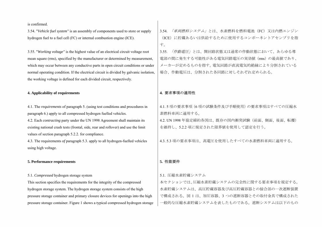
is confirmed.
3.54. "Vehicle fuel system" is an assembly of components used to store or supply
hydrogen fuel to a fuel cell (FC) or internal combustion engine (ICE).
3.54. 「車両燃料システム」とは、水素燃料を燃料電池(FC)又は内燃エンジン
(ICE)に貯蔵あるいは供給するために使用するコンポーネントアセンブリを指
す。
3.55. "Working voltage" is the highest value of an electrical circuit voltage root
mean square (rms), specified by the manufacturer or determined by measurement,
which may occur between any conductive parts in open circuit conditions or under
normal operating condition. If the electrical circuit is divided by galvanic isolation,
the working voltage is defined for each divided circuit, respectively.
3.55. 「作動電圧」とは、開回路状態又は通常の作動状態において、あらゆる導
電部の間に発生する可能性がある電気回路電圧の実効値(rms)の 高値であり、
メーカーが定めるものを指す。電気回路が直流電気的絶縁により分割されている
場合、作動電圧は、分割された各回路に対しそれぞれ定められる。
4. Applicability of requirements
4.1. The requirements of paragraph 5. (using test conditions and procedures in
paragraph 6.) apply to all compressed hydrogen fuelled vehicles.
4. 要求事項の適用性
4.1. 5 項の要求事項(6 項の試験条件及び手順使用)の要求事項はすべての圧縮水
素燃料車両に適用する。
4.2. Each contracting party under the UN 1998 Agreement shall maintain its
existing national crash tests (frontal, side, rear and rollover) and use the limit
values of section paragraph 5.2.2. for compliance.
4.2. UN 1998 年協定締約各国は、既存の国内衝突試験(前面、側面、後面、転覆)
を維持し、5.2.2 項に規定された限界値を使用して認定を行う。
4.3. The requirements of paragraph 5.3. apply to all hydrogen-fuelled vehicles
using high voltage.
4.3. 5.3 項の要求事項は、高電圧を使用したすべての水素燃料車両に適用する。
5. Performance requirements
5.1. Compressed hydrogen storage system
This section specifies the requirements for the integrity of the compressed
hydrogen storage system. The hydrogen storage system consists of the high
pressure storage container and primary closure devices for openings into the high
pressure storage container. Figure 1 shows a typical compressed hydrogen storage
5. 性能要件
5.1. 圧縮水素貯蔵システム
本セクションでは、圧縮水素貯蔵システムの完全性に関する要求事項を規定する。
水素貯蔵システムは、高圧貯蔵容器及び高圧貯蔵容器との接合部の一次遮断装置
で構成される。図 1 は、加圧容器、3 つの遮断容器とその取付金具で構成された
一般的な圧縮水素貯蔵システムを表したものである。遮断システムは以下のもの
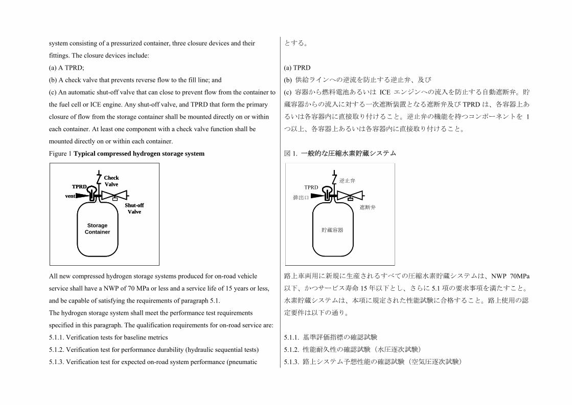
system consisting of a pressurized container, three closure devices and their
fittings. The closure devices include:
(a) A TPRD;
(b) A check valve that prevents reverse flow to the fill line; and
(c) An automatic shut-off valve that can close to prevent flow from the container to
the fuel cell or ICE engine. Any shut-off valve, and TPRD that form the primary
closure of flow from the storage container shall be mounted directly on or within
each container. At least one component with a check valve function shall be
mounted directly on or within each container.
とする。
(a) TPRD
(b) 供給ラインへの逆流を防止する逆止弁、及び
(c) 容器から燃料電池あるいは ICE エンジンへの流入を防止する自動遮断弁。貯
蔵容器からの流入に対する一次遮断装置となる遮断弁及び TPRD は、各容器上あ
るいは各容器内に直接取り付けること。逆止弁の機能を持つコンポーネントを 1
つ以上、各容器上あるいは各容器内に直接取り付けること。
Figure 1 Typical compressed hydrogen storage system
図 1. 一般的な圧縮水素貯蔵システム
All new compressed hydrogen storage systems produced for on-road vehicle
service shall have a NWP of 70 MPa or less and a service life of 15 years or less,
and be capable of satisfying the requirements of paragraph 5.1.
The hydrogen storage system shall meet the performance test requirements
specified in this paragraph. The qualification requirements for on-road service are:
路上車両用に新規に生産されるすべての圧縮水素貯蔵システムは、NWP 70MPa
以下、かつサービス寿命 15 年以下とし、さらに 5.1 項の要求事項を満たすこと。
水素貯蔵システムは、本項に規定された性能試験に合格すること。路上使用の認
定要件は以下の通り。
5.1.1. Verification tests for baseline metrics 5.1.1. 基準評価指標の確認試験
5.1.2. Verification test for performance durability (hydraulic sequential tests) 5.1.2. 性能耐久性の確認試験(水圧逐次試験)
5.1.3. Verification test for expected on-road system performance (pneumatic 5.1.3. 路上システム予想性能の確認試験(空気圧逐次試験)
ContainmentVessel
Shut-offValve
CheckValveTPRD
vent
StorageContainer
ContainmentVessel
Shut-offValve
CheckValveTPRD
vent
StorageContainer
排出口
TPRD 逆止弁
遮断弁
貯蔵容器
sequential tests)
5.1.4. Verification test for service terminating system performance in Fire. 5.1.4. 燃焼時におけるサービス終了システム性能の確認試験
5.1.5. Verification test for performance durability of primary closures.
The test elements within these performance requirements are summarized in
Table 1. The corresponding test procedures are specified in paragraph 6.
5.1.5. 一次遮断装置の性能耐久性確認試験
上記の性能要件に関する試験項目を表 1 にまとめる。各試験手順は 6 項で規定し
ている。
Table 1 Overview of performance qualification test requirements
5.1.1. Verification tests for baseline metrics
5.1.1.1. Baseline initial burst pressure
5.1.1.2. Baseline initial pressure cycle life
5.1.2. Verification test for performance durability (sequential
hydraulic tests)
5.1.2.1. Proof pressure test
5.1.2.2. Drop (impact) test
5.1.2.3. Surface damage
5.1.2.4. Chemical exposure and ambient temperature pressure
cycling tests
5.1.2.5. High temperature static pressure test
5.1.2.6. Extreme temperature pressure cycling
5.1.2.7. Residual proof pressure test
5.1.2.8. Residual strength Burst Test
5.1.3. Verification test for expected on-road performance (sequential
pneumatic tests)
5.1.3.1. Proof pressure test
5.1.3.2. Ambient and extreme temperature gas pressure cycling test
(pneumatic)
5.1.3.3. Extreme temperature static gas pressure leak/permeation test
表 1 性能認定試験要件の概要
5.1.1. 基準評価指標の確認試験
5.1.1.1. 初期破裂圧の基準値
5.1.1.2. 初期圧力サイクル寿命の基準値
5.1.2. 性能耐久性の確認試験(水圧逐次試験)
5.1.2.1. 耐圧試験
5.1.2.2. 落下(衝撃)試験
5.1.2.3. 表面損傷
5.1.2.4. 化学物質暴露及び常温気圧サイクル試験
5.1.2.5. 高温静圧試験
5.1.2.6. 限界温度圧力サイクル
5.1.2.7. 残留耐圧試験
5.1.2.8. 残留強度破裂試験
5.1.3. 路上システム予想性能の確認試験(空気圧逐次試験)
5.1.3.1. 耐圧試験
5.1.3.2. 常温気圧、限界温度気圧サイクル試験(気圧)
5.1.3.3. 限界温度静気圧漏出/透過試験(気圧)
(pneumatic)
5.1.3.4. Residual proof pressure test
5.1.3.5. Residual strength burst test (hydraulic)
5.1.4. Verification test for service terminating performance in fire
5.1.5. Verification test for closure durability
5.1.3.4. 残留耐圧試験
5.1.3.5. 残留強度破裂試験(水圧)
5.1.4. 燃焼時におけるサービス終了システム性能の確認試験
5.1.5. 遮断耐久性の確認試験
5.1.1. Verification tests for baseline metrics 5.1.1. 基準評価指標の確認試験
5.1.1.1. Baseline initial burst pressure
Three (3) new containers randomly selected from the design qualification batch of
at least 10 containers, are hydraulically pressurized until burst (para. 6.2.2.1. test
procedure). The manufacturer shall supply documentation (measurements and
statistical analyses) that establish the midpoint burst pressure of new storage
containers, BPO.
All containers tested shall have a burst pressure within ±10 per cent of BPO and
greater than or equal to a minimum BPmin of 225 per cent NWP.
In addition, containers having glass-fibre composite as a primary constituent to
have a minimum burst pressure greater than 350 per cent NWP.
5.1.1.1. 初期破裂圧の基準値
10 個以上の容器からなる設計承認バッチから、任意に選んだ 3 個の新しい容器に
対し、破裂するまで水圧を加える。(試験手順は 6.2.2.1 項)製造者は(測定値及
び統計分析を記載した)文書を提出し、新しい貯蔵容器の破裂圧の中点値 BPo を
提示すること。
すべての被験容器は、破裂圧が BPo の±10%以内かつ NWP の 225%の 小 BPmin
以上であること。
さらに、容器の主成分はグラスファイバー混合物とし、NWP の 350%超の 小破
裂圧であること。
5.1.1.2. Baseline initial pressure cycle life
Three (3) new containers randomly selected from the design qualification batch are
hydraulically pressure cycled at 20(±5)°C to 125 per cent NWP without rupture for
22,000 cycles or until a leak occurs (para. 6.2.2.2. test procedure). Leakage shall
not occur within a number of Cycles, where the number of Cycles is set
individually by each Contracting Party at 5,500, 7,500 or 11,000 cycles for a
15-year service life.
5.1.1.2. 初期圧力サイクル寿命の基準値
設計承認バッチから、任意に選んだ 3 個の新しい容器に対し、
20(±5%)で NWP の 125%まで水圧サイクルを加え、22,000 サイク
ルまで破裂を生じないこと、あるいは漏出を生じるまで行うこと。
(試験手順は 6.2.2.2 項)サイクル数が終了するまで漏出が生じない
こと。サイクル数は締約国毎に 15 年のサービス寿命で 5,500、7,500、
11,000 サイクルを設定する。
5.1.2. Verification tests for performance durability (Hydraulic sequential tests)
If all three pressure cycle life measurements made in para. 5.1.1.2. are greater than
11,000 cycles, or if they are all within ±25 per cent of each other, then only one (1)
5.1.2. 性能耐久性の確認試験(水圧逐次試験)
5.1.1.2項で測定した3つすべての圧力サイクル寿命が11,000サイクル以上の場合、
あるいはこれらすべてが互いの±25%以内である場合、1 つの容器のみを 5.1.2 項
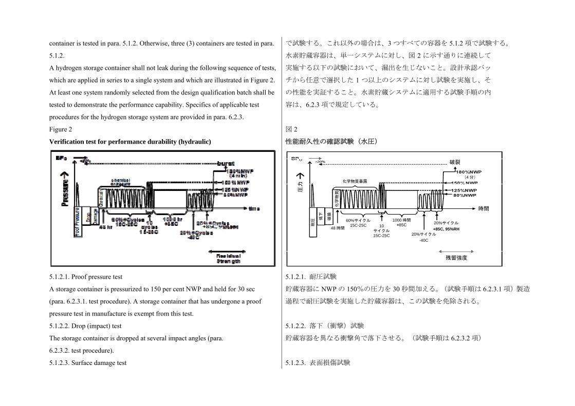
container is tested in para. 5.1.2. Otherwise, three (3) containers are tested in para.
5.1.2.
A hydrogen storage container shall not leak during the following sequence of tests,
which are applied in series to a single system and which are illustrated in Figure 2.
At least one system randomly selected from the design qualification batch shall be
tested to demonstrate the performance capability. Specifics of applicable test
procedures for the hydrogen storage system are provided in para. 6.2.3.
で試験する。これ以外の場合は、3 つすべての容器を 5.1.2 項で試験する。
水素貯蔵容器は、単一システムに対し、図 2 に示す通りに連続して
実施する以下の試験において、漏出を生じないこと。設計承認バッ
チから任意で選択した 1 つ以上のシステムに対し試験を実施し、そ
の性能を実証すること。水素貯蔵システムに適用する試験手順の内
容は、6.2.3 項で規定している。
Figure 2
Verification test for performance durability (hydraulic)
図 2
性能耐久性の確認試験(水圧)
5.1.2.1. Proof pressure test
A storage container is pressurized to 150 per cent NWP and held for 30 sec
(para. 6.2.3.1. test procedure). A storage container that has undergone a proof
pressure test in manufacture is exempt from this test.
5.1.2.1. 耐圧試験
貯蔵容器に NWP の 150%の圧力を 30 秒間加える。(試験手順は 6.2.3.1 項)製造
過程で耐圧試験を実施した貯蔵容器は、この試験を免除される。
5.1.2.2. Drop (impact) test
The storage container is dropped at several impact angles (para.
6.2.3.2. test procedure).
5.1.2.2. 落下(衝撃)試験
貯蔵容器を異なる衝撃角で落下させる。(試験手順は 6.2.3.2 項)
5.1.2.3. Surface damage test 5.1.2.3. 表面損傷試験
圧力
耐圧
低下
破損
化学物質
化学物質暴露
60%サイクル15C-25C
48 時間10
サイクル15C-25C
1000 時間+85C
20%サイクル
-40C
20%サイクル +85C, 95%RH
残留強度
時間
破裂
(4 分)

The storage container is subjected to surface damage (para. 6.2.3.3.
test procedure).
貯蔵容器に表面損傷を加える。(試験手順は 6.2.3.3 項)
5.1.2.4. Chemical exposure and ambient-temperature pressure cycling test
The storage container is exposed to chemicals found in the on-road environment
and pressure cycled to 125 per cent NWP at 20 (±5)°C for 60 per cent number of
Cycles pressure cycles (para. 6.2.3.4. test procedure). Chemical exposure is
discontinued before the last 10 cycles, which are conducted to 150 per cent
NWP.
5.1.2.4. 化学物質暴露及び常温気圧サイクル試験
貯蔵容器を、路上環境に存在する化学物質に暴露し、20(±5)で NWP の 125%の
圧力で圧力サイクル回数の 60%分サイクル試験を実施する。(試験手順は 6.2.3.4
項)化学物質暴露は、 後の 10 サイクル前に終了する。 後の 10 サイクルでは
NWP の 150%で試験を行う。
5.1.2.5. High temperature static pressure test.
The storage container is pressurized to 125 per cent NWP at ≥85°C
for 1,000 hr (para. 6.2.3.5. test procedure).
5.1.2.5. 高温静圧試験
貯蔵容器を≧85で 1,000 時間、NWP の 125%に加圧する。(試験手順は 6.2.3.5
項)
5.1.2.6. Extreme temperature pressure cycling.
The storage container is pressure cycled at ≤ -40°C to 80 per cent NWP for 20 per
cent number of Cycles and at ≥ +85°C and 95 per cent relative humidity to 125 per
cent NWP for 20 per cent number of Cycles (para. 6.2.2.2. test procedure).
5.1.2.6. 限界温度気圧サイクル
貯蔵容器に対し≦-40、NWP の 80%で、サイクル回数の 20%分、加圧サイク
ルを行い、≧+85かつ相対湿度 95%、NWP の 125%でサイクル回数の 20%分
加圧サイクルを実施する。(試験手順は 6.2.2.2 項)
5.1.2.7. Hydraulic residual pressure test. The storage container is pressurized to
180 per cent NWP and held 4 minutes without burst (para. 6.2.3.1. test procedure).
5.1.2.7. 残留水圧試験
貯蔵容器を NWP の 180%で 4 分間加圧し、破裂しないこと。(試験
手順は 6.2.3.1 項)
5.1.2.8. Residual burst strength test
The storage container undergoes a hydraulic burst test to verify that the burst
pressure is at least 80 per cent of the baseline initial burst pressure (BPO)
determined in para. 5.1.1.1. (para. 6.2.2.1. test procedure).
5.1.2.8. 残留破裂強度試験
貯蔵容器に対して水圧破裂試験を実施し、破裂圧が 5.1.1.1 項で規定した初期破裂
圧基準値(BPo)の 80%以上であることを確認する。(試験手順は 6.2.2.1 項)
5.1.3. Verification test for expected on-road performance (Pneumatic sequential
tests)
A hydrogen storage system shall not leak during the following sequence of tests,
which are illustrated in Figure 3. Specifics of applicable test procedures for the
hydrogen storage system are provided in paragraph 6.
5.1.3. 路上予想性能の確認試験(空気圧逐次試験)
水素貯蔵システムは、図 3 に示す以下の連続試験において漏出を生じないこと。
水素貯蔵システムに適用する試験手順の内容は、6 項で規定している。
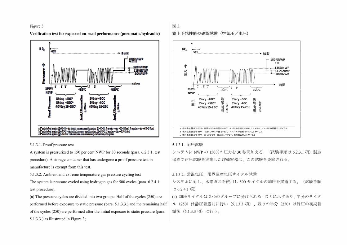
Figure 3
Verification test for expected on-road performance (pneumatic/hydraulic)
図 3.
路上予想性能の確認試験(空気圧/水圧)
5.1.3.1. Proof pressure test
A system is pressurized to 150 per cent NWP for 30 seconds (para. 6.2.3.1. test
procedure). A storage container that has undergone a proof pressure test in
manufacture is exempt from this test.
5.1.3.1. 耐圧試験
システムに NWP の 150%の圧力を 30 秒間加える。(試験手順は 6.2.3.1 項)製造
過程で耐圧試験を実施した貯蔵容器は、この試験を免除される。
5.1.3.2. Ambient and extreme temperature gas pressure cycling test
The system is pressure cycled using hydrogen gas for 500 cycles (para. 6.2.4.1.
test procedure).
5.1.3.2. 常温気圧、限界温度気圧サイクル試験
システムに対し、水素ガスを使用し 500 サイクルの加圧を実施する。(試験手順
は 6.2.4.1 項)
(a) The pressure cycles are divided into two groups: Half of the cycles (250) are
performed before exposure to static pressure (para. 5.1.3.3.) and the remaining half
of the cycles (250) are performed after the initial exposure to static pressure (para.
5.1.3.3.) as illustrated in Figure 3;
(a) 加圧サイクルは 2 つのグループに分けられる:図 3 に示す通り、半分のサイク
ル(250)は静圧暴露前に行い(5.1.3.3 項)、残りの半分(250)は静圧の初期暴
露後(5.1.3.3 項)に行う。
圧力
耐圧
4 分
破裂
時間
漏出
/透過
漏出
/透過
≧
30時間
a 燃料供給/除去サイクル 初期システム平衡で-40 +20の燃料で-40、5 サイクル、<-35の燃料で 5 サイクル b 燃料供給/除去サイクル 初期システム平衡で+50 <-35の燃料で+50、5 サイクル c 燃料供給/除去サイクル 15‐25でサービス(メンテナンス)燃料除去率、50 サイクル
(b) The first group of pressure cycling, 25 cycles are performed to 80 per cent
NWP at ≤ - 40°C, then 25 cycles to 125 per cent NWP at ≥ + 50°C and 95 per cent
relative humidity, and the remaining 200 cycles to 125 per cent NWP at 20 (±5)°C;
The second group of pressure cycling, 25 cycles are performed to 125 per cent
NWP at ≥ + 50°C and 95 per cent relative humidity, then 25 cycles to 80 per cent
NWP at ≤ - 40°C, and the remaining 200 cycles to 125 per cent NWP at 20(±5)°C.
(c) The hydrogen gas fuel temperature is ≤ - 40 °C;
(d) During the first group of 250 pressure cycles, five cycles are performed with
fuel having a temperature of + 20(±5)°C after temperature equilibration of the
system at ≤ - 40°C; five cycles are performed with fuel having a temperature of
≤ - 40°C; and five cycles are performed with fuel having a temperature of ≤ - 40°C
after temperature equilibration of the system at ≥ 50°C and 95 per cent relative
humidity;
(e) Fifty pressure cycles are performed using a de-fuelling rate greater than or
equal to the maintenance de-fuelling rate.
(b) 初のグループの加圧サイクルでは、≦-40で、NWP の 80%で 25 サイク
ル実施し、続いて≧+50及び相対湿度 95%で、NWP の 125%で 25 サイクル実
施し、残りの 200 サイクルは 20(±5)で、NWP の 125%で実施する。
もう一方の加圧サイクルでは、≧+50°C 及び相対湿度 95%で、NWP の 125%で
25 サイクル実施し、続いて≦-40°C で、NWP の 80%で 25 サイクル実施し、残
りの 200 サイクルは 20(±5)で、NWP の 125%で実施する。
(c) 水素ガスの温度は≦-40とする。
(d) 250 回の加圧サイクルの 初のグループでは、システムの温度平衡後≦-40
で、燃料温度が+20(±5)で 5 サイクル実施。燃料温度が≦-40で 5 サイクル
実施。温度平衡後≧50かつ相対湿度 95%で、燃料温度が≦-40で 5 サイクル
実施する。
(e) メンテナンス時の燃料除去速度以上の燃料除去速度を使用して加圧サイクル
を 50 回実施する。
5.1.3.3. Extreme temperature static pressure leak/permeation test. 5.1.3.3. 限界温度静圧漏出/透過試験
(a) The test is performed after each group of 250 pneumatic pressure cycles in
paragraph 5.1.3.2.;
(b) The maximum allowable hydrogen discharge from the compressed hydrogen
storage system is 46 mL/h/L water capacity of the storage system. (para. 6.2.4.2.
test procedure) ;
(a) 試験は 5.1.3.2 項に規定された 250 回の気圧サイクルの各グループを実施した
後に行う。
(b) 圧縮水素貯蔵システムから排出される 大許容水素量は
貯蔵システムの水容量の 46mL/h/L である。(試験手順は 6.2.4.2 項)

(c) If the measured permeation rate is greater than 0.005 mg/sec (3.6 Nml/min), a
localized leak test is performed to ensure no point of localized external leakage is
greater than 0.005 mg/sec (3.6 Nml/min) (para. 6.2.4.3. test procedure).
(c) 透過測定値が 0.005mg/秒(3.6Nml/分)を超える場合、局所的な漏出試験を実
施し、外部への漏出が 0.005mg/秒(3.6Nml/分)を超える箇所がないことを確認す
る。(試験手順は 6.2.4.3 項)
5.1.3.4. Residual proof pressure test (hydraulic)
The storage container is pressurized to 180 per cent NWP and held 4 minutes
without burst (para. 6.2.3.1. test procedure).
5.1.3.4. 残留耐圧試験(水圧)
貯蔵容器を NWP の 180%で 4 分間加圧し、破裂しないこと。(試験手順は 6.2.3.1
項)
5.1.3.5. Residual strength burst test (hydraulic)
The storage container undergoes a hydraulic burst to verify that the burst pressure
is within 20 per cent of the baseline burst pressure determined in para. 5.1.1.1.
(para. 6.2.2.1. test procedure).
5.1.3.5. 残留強度破裂試験(水圧)
貯蔵容器に対して水圧破裂試験を実施し、破裂圧が 5.1.1.1 項で規定した初期破裂
圧基準値の 20%以内であることを確認する。(試験手順は 6.2.2.1 項)
5.1.4. Verification test for service terminating performance in fire
This section describes the fire test with compressed hydrogen as the test gas.
Containers tested with hydrogen gas shall be accepted by all Contracting Parties.
However, Contracting Parties under the 1998 Agreement may choose to use
compressed air as an alternative test gas for certification of a container for use only
within their countries or regions.
A hydrogen storage system is pressurized to NWP and exposed to fire (para.
6.2.5.1. test procedure). A temperature-activated pressure relief device shall
release the contained gases in a controlled manner without rupture.
5.1.4. 燃焼時におけるサービス終了性能の確認試験
本セクションでは、圧縮水素を試験気体とする火災試験について規定する。水素
を使って試験する被験容器は、すべての締約国による承認を要する。しかし 1998
年協定の締約国は、代替の試験気体として圧縮空気を使用し、自国内又は地域内
限定で使用する容器の認定を行うことができる。
水素貯蔵システムを NWP に加圧して火中にさらす。(試験手順は 6.2.5.1 項)温
度作動型圧力除去装置により、破裂することなく内蔵ガスの排出を制御する。
5.1.5. Verification test for performance durability of primary closures
Manufacturers shall maintain records that confirm that closures that isolate the
high pressure hydrogen storage system (the TPRD(s), check valve(s) and shut-off
valve(s) shown in Figure 1) comply with the requirements described in the
remainder of this Section.
The entire storage system does not have to be re-qualified (para. 5.1.) if these
closure components (components in Figure 1 excluding the storage container) are
exchanged for equivalent closure components having comparable function,
5.1.5. 一次遮断装置の性能耐性確認試験
製造者は、高圧の水素貯蔵システムを切り離す遮断装置(図 1 の TPRD、逆止弁、
及び遮断弁)が本セクションの以降の規定に適合することを確認する記録を残す
こと。
これらの遮断装置(貯蔵容器を除く図 1 の装置)を同等の機能、フィッティング、
材質、強度、寸法を持ち、元の装置と同じ承認試験に合格した同等の遮断装置と
交換した場合、貯蔵システム全体を再認定(5.1 項)する必要はない。ただし、TPRD
fittings, materials, strength and dimensions, and qualified for performance using
the same qualification tests as the original components. However, a change in
TPRD hardware, its position of installation or venting lines requires
re-qualification with fire testing according to para. 5.1.4.
ハードウェア、その取り付け位置、排気ラインが変更された場合、5.1.4 項に規定
された火災試験を行い再認定を受ける必要がある。
5.1.5.1. TPRD qualification requirements
Design qualification testing shall be conducted on finished pressure relief devices
which are representative of normal production. The TPRD shall meet the
following performance qualification requirements:
5.1.5.1. TPRD 認定要件
正常な生産品を代表する圧力除去装置の完成品に対し、設計認定試験を実施する。
TPRD は以下の性能認定要件を満たすこと。
(a) Pressure cycling test (para. 6.2.6.1.1.);
(b) Accelerated life test (para. 6.2.6.1.2.);
(c) Temperature cycling test (para. 6.2.6.1.3.);
(d) Salt corrosion resistance test (para. 6.2.6.1.4.);
(e) Vehicle environment test (para. 6.2.6.1.5.);
(f) Stress corrosion cracking test (para. 6.2.6.1.6.);
(g) Drop and vibration test (para. 6.2.6.1.7.);
(h) Leak test (para. 6.2.6.1.8.);
(i) Bench top activation test (para. 6.2.6.1.9.);
(j) Flow rate test (para. 6.2.6.1.10.).
(a) 圧力サイクル試験(6.2.6.1.1.項)
(b) 加速寿命試験(6.2.6.1.2.項)
(c) 温度サイクル試験(6.2.6.1.3.項)
(d) 耐塩腐食試験(6.2.6.1.4.項)
(e) 車両環境試験(6.2.6.1.5.項)
(f) 応力腐食亀裂試験(6.2.6.1.6.項)
(g) 落下及び振動試験(6.2.6.1.7.項)
(h) 漏出試験(6.2.6.1.8.項)
(i) 卓上起動試験(6.2.6.1.9.項)
(j) 流量試験(6.2.6.1.10.項)
5.1.5.2. Check valve and automatic shut-off valve qualification on requirements
Design qualification testing shall be conducted on finished check valves and
shut-off valves which are representative of normal production. The valve units
shall meet the following performance qualification requirements:
5.1.5.2. 逆止弁及び自動遮断弁の認定要件
正常な生産品を代表する逆止弁及び遮断弁の完成品に対し、設計認定試験を実施
する。弁装置は以下の性能認定要件を満たすこと。
(a) Hydrostatic strength test (para. 6.2.6.2.1.);
(b) Leak test (para. 6.2.6.2.2.);
(c) Extreme temperature pressure cycling test (para. 6.2.6.2.3.);
(d) Salt corrosion resistance test (para. 6.2.6.2.4.);
(e) Vehicle environment test (para. 6.2.6.2.5.);
(a) 静水圧強度試験(6.2.6.2.1.項)
(b) 漏出試験(6.2.6.2.2.項)
(c) 限界温度加圧サイクル試験(6.2.6.2.3.項)
(d) 耐塩腐食試験(6.2.6.2.4.項)
(e) 車両環境試験(6.2.6.2.5.項)
(f) Atmospheric exposure test (para. 6.2.6.2.6.);
(g) Electrical tests (para. 6.2.6.2.7.);
(h) Vibration test (para. 6.2.6.2.8.);
(i) Stress corrosion cracking test (para. 6.2.6.2.9.);
(j) Pre-cooled hydrogen exposure test (para. 6.2.6.2.10.).
(f) 屋外暴露試験(6.2.6.2.6.項)
(g) 電気的試験(6.2.6.2.7.項)
(h) 振動試験(6.2.6.2.8.項)
(i) 応力腐食亀裂試験(6.2.6.2.9.項)
(j) 予冷水素暴露試験(6.2.6.2.10.項)
5.1.6. Labelling
A label shall be permanently affixed on each container with at least the following
information: name of the manufacturer, serial number, date of manufacture, NWP,
type of fuel, and date of removal from service. Each container shall also be marked
with the number of cycles used in the testing programme as per para. 5.1.1.2. Any
label affixed to the container in compliance with this section shall remain in place
and be legible for the duration of the manufacturer’s recommended service life for
the container.
Date of removal from service shall not be more than 15 years after the date of
manufacture.
5.1.6. ラベル表示
各容器には、恒久的なラベルを取り付けること。ラベルには 低でも、製造者名、
シリアル番号、製造日、NWP、燃料の種類、サービス停止日を記載すること。ま
た各容器には、5.1.1.2 項に規定された試験プログラムで使用したサイクル数を表
示する。本セクションの規定に従い取り付けるラベルは、容器が製造者の推奨す
るサービス寿命を迎えるまでの期間中、外れることなく、判読できる状態を維持
すること。
サービス停止日は、製造日から 15 年を超えてはならない。
5.2. Vehicle fuel system
This section specifies requirements for the integrity of the hydrogen fuel delivery
system, which includes the hydrogen storage system, piping, joints, and
components in which hydrogen is present.
5.2. 車両の燃料システム
本セクションでは、水素燃料供給システムの完全性に関する要求事項を規定する。
これには、水素貯蔵システム、配管、継手、水素が介在するコンポーネントが含
まれる。
5.2.1. In-use fuel system integrity 5.2.1. 使用中の燃料システムの完全性
5.2.1.1. Fuelling receptacle requirements 5.2.1.1. 燃料投入口に関する要求事項
5.2.1.1.1. A compressed hydrogen fuelling receptacle shall prevent reverse flow to
the atmosphere. Test procedure is visual inspection.
5.2.1.1.1. 圧縮水素燃料の投入口は、空気の逆流を防ぐ構造であること。試験は目
視検査で行う。
5.2.1.1.2. Fuelling receptacle label A label shall be affixed close to the fuelling
receptacle; for instance inside a refilling hatch, showing the following information:
fuel type, NWP, date of removal from service of containers.
5.2.1.1.2. 燃料投入口には、その近く、例えば再充填ハッチ内部にラベルを貼り付
けること。ラベルには、燃料の種類、NWP、容器のサービス停止日を記載するこ
と。
5.2.1.1.3. The fuelling receptacle shall be mounted on the vehicle to ensure 5.2.1.1.3. 燃料投入口は、燃料供給ノズルが車両に確実に固定されるように取り付
positive locking of the fuelling nozzle. The receptacle shall be protected from
tampering and the ingress of dirt and water (e.g. installed in a compartment which
can be locked). Test procedure is by visual inspection.
けること。投入口は、異物、ごみ、水分の混入を防ぐものであること。(例えば
施錠可能な区画内に設置する。)試験は目視検査で行う。
5.2.1.1.4. The fuelling receptacle shall not be mounted within the external energy
absorbing elements of the vehicle (e.g. bumper) and shall not be installed in the
passenger compartment, luggage compartment and other places where hydrogen
gas could accumulate and where ventilation is not sufficient. Test procedure is by
visual inspection.
5.2.1.1.4. 燃料投入口は、車両外部のエネルギー吸収体(例、バンパー)内、客室
内、荷物室内、その他水素ガスが蓄積する場所、換気が充分でない場所に取り付
けてはならない。試験は目視検査で行う。
5.2.1.2. Over-pressure protection for the low pressure system (para. 6.1.6. test
procedure)
The hydrogen system downstream of a pressure regulator shall be protected
against overpressure due to the possible failure of the pressure regulator. The set
pressure of the overpressure protection device shall be lower than or equal to the
maximum allowable working pressure for the appropriate section of the hydrogen
system.
5.2.1.2. 低圧システムの過圧保護(試験手順は 6.1.6 項)
圧力調整器下流の水素システムには、圧力調整器の故障による過圧に対する保護
を施すこと。過圧保護の設定値は、水素システムの対応部位の 大許容動作圧以
下とする。
5.2.1.3. Hydrogen discharge systems 5.2.1.3. 水素排出システム
5.2.1.3.1. Pressure relief systems (para. 6.1.6. test procedure) 5.2.1.3.1. 圧力除去システム(試験手順は 6.1.6 項)
(a) Storage system TPRDs. The outlet of the vent line, if present, for hydrogen gas
discharge from TPRD(s) of the storage system shall be protected by a cap;
(b) Storage system TPRDs. The hydrogen gas discharge from TPRD(s) of the
storage system shall not be directed:
(i) Into enclosed or semi-enclosed spaces;
(ii) Into or towards any vehicle wheel housing;
(iii) Towards hydrogen gas containers;
(iv) Forward from the vehicle, or horizontally (parallel to road) from the back or
sides of the vehicle.
(c) Other pressure relief devices (such as a burst disk) may be used outside the
(a) 貯蔵システム TPRD 貯蔵システムの TPRD から水素ガスを排出する排気ラ
インに排出口がある場合、これをキャップで保護すること。
(b) 貯蔵システム TPRD 貯蔵システムの TPRD からの水素ガスの排出は、以下
の方向に行わないこと。
(i) 密閉空間、あるいは半密閉空間方向
(ii) 車両のホイールハウジング内、あるいはその方向
(iii) 水素ガス容器方向
(iv) 車両の前方向、車両の後部あるいは側面から水平(路面と平行)方向.
(c) その他の圧力除去装置(バーストディスクなど)を、水素貯蔵システム外部
hydrogen storage system. The hydrogen gas discharge from other pressure relief
devices shall not be directed:
(i) Towards exposed electrical terminals, exposed electrical switches or other
ignition sources;
(ii) Into or towards the vehicle passenger or cargo compartments;
(iii) Into or towards any vehicle wheel housing;
(iv) Towards hydrogen gas containers.
で使用することができる。他の圧力除去装置からの水素ガスの排出は、以下の
方向に行わないこと。
(i) 露出した電気端子、露出した電気スイッチ、又はその他の点火源方向
(ii) 車両の客室又は貨物室内、あるいはその方向
(iii) 車両のホイールハウジング内、あるいはその方向
(iv) 水素ガス容器方向
5.2.1.3.2. Vehicle Exhaust System (para. 6.1.4. test procedure)
At the vehicle exhaust system’s point of discharge, the hydrogen concentration
level shall:
5.2.1.3.2. 車両の排気システム(試験手順は 6.1.4 項)
車両の排気システムの排出点において、水素濃度は以下の通りであること。
(a) Not exceed 4 per cent average by volume during any moving three-second time
interval during normal operation including start-up and shutdown;
(b) And not exceed 8 per cent at any time (para. 6.1.4. test procedure).
(a) 起動時及び停止時を含めた通常の運用中、任意の 3 秒間において容量平均
4%を超えないこと。
(b) かついかなる時点でも 8%を超えないこと。(試験手順は 6.1.4 項)
5.2.1.4. Protection against flammable conditions: single failure conditions 5.2.1.4. 引火に対する保護:単一故障条件
5.2.1.4.1. Hydrogen leakage and/or permeation from the hydrogen storage system
shall not directly vent into the passenger, luggage, or cargo compartments, or to
any enclosed or semi-enclosed spaces within the vehicle that contains unprotected
ignition sources.
5.2.1.4.1. 水素貯蔵システムからの水素漏出及び/又は透過が、車両の客室、荷物
室、貨物室、あるいは点火源を内蔵する保護機構のない密閉、半密閉空間へ直接
排出されないこと。
5.2.1.4.2. Any single failure downstream of the main hydrogen shut off valve shall
not result in any level of a hydrogen concentration in anywhere in the passenger
compartment according to test procedure para. 6.1.3.2.
5.2.1.4.2. 主要な水素遮断弁の下流で発生した単一故障により、客室内のいかなる
場所でも、6.1.3.2 項の試験手順に規定した水素濃度を生じないこと。
5.2.1.4.3. If, during operation, a single failure results in a hydrogen concentration
exceeding 2 ± 1.0 per cent by volume in air in the enclosed or semi-enclosed
spaces of the vehicle, then a warning shall be provided (para. 5.2.1.6.). If the
hydrogen concentration exceeds 3 ± 1.0 per cent by volume in the air in the
enclosed or semi-enclosed spaces of the vehicle, the main shutoff valve shall be
closed to isolate the storage system. (para. 6.1.3. test procedure).
5.2.1.4.3. 運用中に単一故障による水素濃度が、車両の密閉又は半密閉空間におい
て空気中で 2±1.0 容量%を超えた場合、警報を発すること(5.2.1.6 項)。水素濃
度が車両の密閉又は半密閉空間において空気中で 3±1.0 容量%を超えた場合、一
次遮断弁が閉じ、貯蔵システムを切り離すこと。(試験手順は 6.1.3 項)
5.2.1.5. Fuel system leakage
The hydrogen fuelling line and the hydrogen system(s) downstream of the main
shut off valve(s) shall not leak. Compliance shall be verified at NWP (para. 6.1.5.
test procedure).
5.2.1.5. 燃料システムにおける漏出
一次遮断弁の下流にある水素供給ライン及び水素システムは、漏出がないこと。
NWP で適合性を確認すること。(試験手順は 6.1.5 項)
5.2.1.6. Tell-tale signal warning to driver
The warning shall be given by a visual signal or display text with the following
properties:
5.2.1.6. 表示シグナルによる運転者への警告
警告は以下の条件を満たした視覚信号又は表示により行う。
(a) Visible to the driver while in the driver's designated seating position with the
driver's seat belt fastened;
(b) Yellow in colour if the detection system malfunctions and shall be red in
compliance with section para. 5.2.1.4.3;
(c) When illuminated, shall be visible to the driver under both daylight and night
time driving conditions;
(d) Remains illuminated when 2 ± 1.0 per cent concentration or detection
malfunction) exists and the ignition locking system is in the "On" ("Run") position
or the propulsion system is activated.
(a) 運転者が運転席においてシートベルトを装着した状態で視認できること。
(b) 検出システムが誤動作した場合は黄色、5.2.1.4.3 項を満たす場合は赤色であ
ること。
(c) 点灯時、昼間、夜間いずれの運転時も運転者が視認できること。
(d) 2±1.0%の濃度が検出されている間、若しくは検出システム故障が発生してい
る間は継続して点灯し、かつ点火ロックシステムが「オン」(「作動」)状態、
又は推進システムが作動していること。
5.2.2. Post-crash fuel system integrity 5.2.2. 衝突後における燃料システムの完全性
5.2.2.1. Fuel leakage limit
The volumetric flow of hydrogen gas leakage shall not exceed an average of 118
NL per minute for 60 minutes after the crash (para. 6.1.1. test procedures).
5.2.2.1. 燃料漏出限界
水素ガス漏出の体積流量は、衝突後 60 分間、平均 118NL/分を超えないこと。(試
験手順は 6.1.1 項)
5.2.2.2. Concentration limit in enclosed spaces
Hydrogen gas leakage shall not result in a hydrogen concentration in the air greater
than 3 ± 1.0 per cent] by volume in the passenger, luggage and cargo
compartments (para. 6.1.2. test procedures). The requirement is satisfied if it is
confirmed that the shut-off valve of the storage system has closed within 5 seconds
of the crash and no leakage from the storage system.
5.2.2.2. 密閉空間内における濃度限界
水素ガス漏出により、客室、荷物室、貨物室内の空気中濃度が 3±1.0%を超えない
こと。(試験手順は 6.1.2 項)衝突後 5 秒以内に貯蔵システムの遮断弁が閉じ、貯
蔵システムからの漏出がない場合、要件を満たしたと見なす。

5.2.2.3. Container Displacement
The storage container(s) shall remain attached to the vehicle at a minimum of one
attachment point.
5.2.2.3. 容器の固定
貯蔵容器は、1 か所以上の固定場所で車両に固定されていること。
5.3.Electrical safety 5.3. 電気的安全
5.3.1. Electrical Safety requirements - in-use 5.3.1. 電気的安全要件-使用中
5.3.1.1. General
Paragraph 5.3.1. applies to the electric power train of fuel cell vehicles equipped
with one or more traction motor(s) operated by electric power and not permanently
connected to the grid, as well as their high voltage components and systems which
are conductively connected to the high voltage bus of the electric power train.
5.3.1.1. 概要
5.3.1 項は、電力で作動し、グリッドに恒久的に接続されていない 1 つ又は複数の
トラクションモーターを持つ燃料電池車両の電気パワートレーン、及び電気パワ
ートレーンの高電圧バスにコンダクティブ接続されているその高電圧コンポーネ
ントとシステムに適用する。
5.3.1.2. Requirements for protection against electric shock 5.3.1.2. 感電に対する保護要件
5.3.1.2.1. Protection against electric shock
These electrical safety requirements apply to high voltage buses under conditions
where they are not connected to external high voltage power supplies.
5.3.1.2.1. 感電に対する保護
これらの電気安全要件は、外部の高電圧電源に接続されていない状態の高電圧バ
スに適用する。
5.3.1.2.2. Protection against direct contact
The protection against direct contact with live parts shall comply with paragraphs
5.3.1.2.2.1. and 5.3.1.2.2.2. These protections (solid insulator, electrical protection
barrier, enclosure, etc.) shall not be opened, disassembled or removed without the
use of tools.
5.3.1.2.2. 直接接触に対する保護
活電部への直接接触に対する保護は、5.3.1.2.2.1 項及び 5.3.1.2.2.2 項に適合するも
のとする。これらの保護(固体の絶縁体、バリヤ、エンクロージャなど)は、工
具を使用せずに開放、分解又は除去できないものとする。
5.3.1.2.2.1. For protection of live parts inside the passenger compartment or
luggage compartment, the protection degree IPXXD shall be provided.
5.3.1.2.2.1. 客室又は荷物室内の活電部の保護については、保護等級 IPXXD を条
件とするものとする。
5.3.1.2.2.2. For protection of live parts in areas other than the passenger
compartment or luggage compartment, the protection degree IPXXB shall be
satisfied.
5.3.1.2.2.2. 客室又は荷物室以外の区域内の活電部の保護については、保護等級
IPXXB を満たすものとする。
5.3.1.2.2.3. Connectors
Connectors (including vehicle inlet) are deemed to meet this requirement if:
5.3.1.2.2.3. コネクタ
コネクタ(車両インレットを含む)は、以下の場合、本要件を満たすとみなされ
る:

(a) They comply with paragraphs 5.3.1.2.2.1. and 5.3.1.2.2.2. when separated
without the use of tools; or
(b) They are located underneath the floor and are provided with a locking
mechanism; or
(c) They are provided with a locking mechanism and other components shall be
removed with the use of tools in order to separate the connector; or
(d) The voltage of the live parts becomes equal or below DC 60V or equal or
below AC 30V (rms) within 1 second after the connector is separated.
(a) 工具を使用せずに分離した時、5.3.1.2.2.1 項及び 5.3.1.2.2.2 項に適合する場合、
又は、
(b) 床下に位置し、かつロック機構を備えている場合、又は、
(c) ロック機構を備えており、コネクタを分離するためには工具を使用してその
他の構成部品を除去するものとされている場合、又は、
(d) コネクタ分離後 1 秒以内に活電部の電圧が DC60V 以下又は AC30V(rms)以
下になる場合。
5.3.1.2.2.4. Service disconnect
For a service disconnect which can be opened, disassembled or removed without
tools, it is acceptable if protection degree IPXXB is satisfied when it is opened,
disassembled or removed without tools.
5.3.1.2.2.4. サービスディスコネクト
工具を使用せずに開放、分解又は除去できるサービスディスコネクトについて
は、工具を使用せずに開放、分解又は除去された状態で保護等級 IPXXB が満た
される場合は許容される。
5.3.1.2.2.5. Marking 5.3.1.2.2.5. マーキング
5.3.1.2.2.5.1. The symbol shown in Figure 4 shall appear on or near the REESS.
The symbol background shall be yellow, the bordering and the arrow shall be
black.
5.3.1.2.2.5.1. 図 4 に示す記号を REESS 上又はその近くに表示するものとする。記
号の背景は黄色とし、縁及び矢印は黒色とする。
Figure 4
Marking of high voltage equipment
図 4
高電圧装置のマーキング
5.3.1.2.2.5.2. The symbol shall be visible on enclosures and electrical protection
barriers, which, when removed, expose live parts of high voltage circuits. This
provision is optional to any connectors for high voltage buses. This provision shall
not apply to any of the following cases
5.3.1.2.2.5.2. 当該記号は、除去された時に高電圧回路の活電部が露出されるエン
クロージャ及びバリヤ上にも表示するものとする。高電圧バスのコネクタについ
ては、本規定は任意である。本規定は、以下の場合のいずれにも適用しないもの
とする:
(a) Where electrical protection barriers or enclosures cannot be physically (a) 工具を使用してその他の車両構成部品を除去しない限り、バリヤ又はエンク
accessed, opened, or removed; unless other vehicle components are removed with
the use of tools;
(b) Where electrical protection barriers or enclosures are located underneath the
vehicle floor.
ロージャへの物理的な接近、その開放又は除去ができない場合、
(b) バリヤ又はエンクロージャが車両床下に位置する場合。
5.3.1.2.2.5.3. Cables for high voltage buses which are not located within
enclosures shall be identified by having an outer covering with the colour orange.
5.3.1.2.2.5.3. エンクロージャ内に位置しない高電圧バス用ケーブルは、橙色の外
部被覆を施すことにより識別するものとする。
5.3.1.2.3. Protection against indirect contact 5.3.1.2.3. 間接接触に対する保護
5.3.1.2.3.1. For protection against electric shock which could arise from indirect
contact, the exposed conductive parts, such as the conductive electrical protection
barrier and enclosure, shall be conductively connected and secured to the electrical
chassis with electrical wire or ground cable, by welding, or by connection using
bolts, etc. so that no dangerous potentials are produced.
5.3.1.2.3.1. 間接接触から生じる可能性がある感電に対する保護については、導電
体のバリヤ及びエンクロージャなどの露出導電部は、危険な電位を生じないよ
う、電線若しくはアース線による接続又は溶接又はボルトなどを使用した接続に
より直流電気的に電気的シャシーに確実に接続されているものとする。
5.3.1.2.3.2. The resistance between all exposed conductive parts and the electrical
chassis shall be lower than 0.1 ohm when there is current flow of at least 0.2
amperes. Demonstrated by using one of the test procedures described in para.
6.3.4.
This requirement is satisfied if the galvanic connection has been established by
welding. In case of doubts a measurement shall be made.
5.3.1.2.3.2. すべての露出導電部と電気的シャシーの間の抵抗値は、少なくとも
0.2A の電流が流れている時に 0.1Ω未満とする。6.3.4.項に規定される試験手順の
うち 1 つを用いて証明するものとする。
直流電気的接続が溶接により確立されている場合、本要件は満たされる。疑いが
ある場合、測定を行う。
5.3.1.2.3.3. In the case of motor vehicles which are connected to the grounded
external electric power supply through the conductive connection, a device to
enable the conductive connection of the electrical chassis to the earth ground shall
be provided.
The device shall enable connection to the earth ground before exterior voltage is
applied to the vehicle and retain the connection until after the exterior voltage is
removed from the vehicle.
Compliance to this requirement may be demonstrated either by using the connector
specified by the car manufacturer, or by analysis (e.g. visual inspection, drawings
5.3.1.2.3.3. 接地された外部電源にコンダクティブ接続により接続することが意
図された車両の場合は、接地への電気的シャシーの直流電気的接続を可能にする
装置を備えるものとする。
当該装置は、車両に外部電圧が掛けられる前に接地への接続を可能にし、車両か
ら外部電圧が除去された後まで接続を維持すべきものとする。
本要件への適合は、自動車メーカー指定のコネクタを使用すること、又は分析
(例、目視検査、図面など)を行うことのいずれかにより証明することができる。
etc.).
5.3.1.2.4. Isolation resistance monitoring system 5.3.1.2.4. 絶縁抵抗監視システム
5.3.1.2.4.1. In fuel cell vehicles, DC high voltage buses shall have an on-board
isolation resistance monitoring system together with a warning to the driver if the
isolation resistance drops below the minimum required value of 100 ohms/volt.
The function of the on-board isolation resistance monitoring system shall be
confirmed as described in para. 6.3.2.
The isolation resistance between the high voltage bus of the coupling system for
charging the REESS, which is not energized in conditions other than that during
the charging of the REESS, and the electrical chassis need not to be monitored.
5.3.1.2.4.1. 燃料電池車両の高電圧 DC バスは、車載絶縁抵抗監視システム及び絶
縁抵抗が規定下限値の 100Ω/ボルト未満に低下した場合に運転者に対して発する
警告を備えていること。車載絶縁抵抗監視システムの機能は、6.3.2 項の規定に従
い確認する。
REESS 充電時以外は加圧されない REESS 充電用結合システムの高電圧バスと電
気的シャシー間の絶縁抵抗は、監視する必要はない。
5.3.1.2.4.2. Electric power train consisting of separate DC or AC buses
If AC high voltage buses and DC high voltage buses are conductively isolated
from each other, isolation resistance between the high voltage bus and the
electrical chassis shall have a minimum value of 100 ohms/volt of the working
voltage for DC buses, and a minimum value of 500 ohms/volt of the working
voltage for AC buses.
The measurement shall be conducted according to para. 6.3.1.
5.3.1.2.4.2. 分離された DC バス又は AC バスで構成された電気パワートレーン
AC 高電圧バスと DC 高電圧バスが直流電気的に互いに絶縁されている場合に
は、高電圧バスと電気的シャシーの間の絶縁抵抗は、DC バスについては 小値
が作動電圧1V当たり100Ω、ACバスについては 小値が作動電圧1V当たり500Ω
であるものとする。
測定は、6.3.1 項に従って実施するものとする。
5.3.1.2.4.3. Electric power train consisting of combined DC- and AC-buses
If AC high voltage buses and DC high voltage buses are galvanically connected,
isolation resistance between the high voltage bus and the electrical chassis shall
have a minimum value of 500 Ω/volt of the working voltage.
However, if all AC high voltage buses are protected by one of the two following
measures, isolation resistance between the high voltage bus and the electrical
chassis shall have a minimum value of 100 ohms/volt of the working voltage.
5.3.1.2.4.3. 複合 DC 及び AC バスで構成された電気パワートレーン
AC 高電圧バスと DC 高電圧バスが直流電気的に接続されている場合には、高電
圧バスと電気的シャシーの間の絶縁抵抗は、 小値が作動電圧 1V 当たり 500Ω
であるものとする。
ただし、以下の 2 つの措置のいずれか 1 つによってすべての AC 高電圧バスが保
護されている場合には、高電圧バスと電気的シャシーの間の絶縁抵抗は、 小値
が作動電圧 1V 当たり 100Ωであるものとする。
(a) Double or more layers of solid insulators, electrical protection barriers or
enclosures that meet the requirement in paragraph 5.3.1.2.3. independently, for
example wiring harness;
(a) 個別に 5.3.1.2.3 項の要件を満たす、2 層以上の固体の絶縁体、バリヤ又はエ
ンクロージャ(例:配線ハーネス)。
(b) Mechanically robust protections that have sufficient durability over vehicle
service life such as motor housings, electronic converter cases or connectors.
(b) 車両の耐用期間にわたり十分な耐久性を有する機械的に頑丈な保護(モータ
ーハウジング、電子式コンバーターケース又はコネクタなど)。
5.3.1.2.4.4. Isolation resistance requirement for the coupling system for charging
the REESS.
For the vehicle inlet intended to be conductively connected to the grounded
external AC power supply and the electrical circuit that is conductively connected
to the vehicle inlet during charging the REESS, the isolation resistance between
the high voltage bus and the electrical chassis shall be at least 1M ohms when the
charger coupler is disconnected. During the measurement, the REESS may be
disconnected. The measurement shall be conducted according to para. 6.3.1.
5.3.1.2.4.4. REESS 充電用連結システムに関する絶縁抵抗要件
接地された外部 AC電源にコンダクティブ接続により接続することが意図された
車両インレット、並びに REESS 充電中、車両インレットに直流電気的に接続さ
れている電気回路については、高電圧バスと電気的シャシーの間の絶縁抵抗は、
充電器カプラーの接続が外れている時に少なくとも 1MΩ とする。測定中は
REESS の接続を外してもよい。測定は、6.3.1 項に従って実施するものとする。
5.3.1.3. Functional safety
At least a momentary indication shall be given to the driver when the vehicle is in
"active driving possible mode''.
However, this provision does not apply under conditions where an internal
combustion engine provides directly or indirectly the vehicle´s propulsion power
upon start up.
When leaving the vehicle, the driver shall be informed by a signal (e.g. optical or
audible signal) if the vehicle is still in the active driving possible mode.
If the on-board REESS can be externally charged, vehicle movement by its own
propulsion system shall be impossible as long as the connector of the external
electric power supply is physically connected to the vehicle inlet.
This requirement shall be demonstrated by using the connector specified by the car
manufacturer.
The state of the drive direction control unit shall be identified to the driver.
5.3.1.3. 機能安全
車両が「自走可能状態」にある時は、運転者に対し、少なくとも瞬時的な表示が
なされるものとする。
ただし、本規定は、内燃エンジンが直接的又は間接的に車両の起動時に推進力を
提供している状態においては適用しない。
運転者が車両を離れる時、車両が依然として自走可能状態にある場合には、信号
(例:光学信号又は音声信号)により運転者に知らせるものとする。
車載 REESS の外部充電が可能な場合には、外部電源のコネクタが車両インレッ
トに物理的に接続されている限り、車両自体の推進システムによる車両の動きは
不可能であるものとする。
本要件は、自動車メーカー指定のコネクタを用いて証明するものとする。
運転方向コントロールユニットの状態を運転者が認識できるようにするものと
する。
5.3.2. Electric safety requirements – post-crash 5.3.2. 電気的安全要件-衝突後
5.3.2.1. General
Fuel cell vehicles equipped with electric power train shall comply with the
5.3.2.1. 概要
電気パワートレーンを装備した燃料電池車両は、5.3.2.2 項から 5.3.2.4 項までの規
requirements of paragraphs 5.3.2.2. to 5.3.2.4. This can be met by a separate
impact test provided that the electrical components do not influence the occupant
protection performance of the vehicle type as defined in the impact regulation. In
case of this condition the requirements of paras. 5.3.2.2. to 5.3.2.4. shall be
checked in accordance with the methods set out in para. 6.3.5.
定に適合すること。個別に衝撃試験を実施し、電気コンポーネントが、衝撃に関
する規定で定められた当該車両型式の乗員保護性能に影響を及ぼすことがなけ
れば適合していると見なす。当該条件では、5.3.2.2 項から 5.3.2.4 項までの要求事
項を 6.3.5 項で規定した方法に従い確認すること。
5.3.2.2. Protection against electric shock
After the impact at least one of the three criteria specified in paragraphs 5.3.2.2.1.
to 5.3.2.2.3. shall be met.
If the vehicle has an automatic disconnect function, or device(s) that conductively
divide the electric power train circuit during driving condition, at least one of the
following criteria shall apply to the disconnected circuit or to each divided circuit
individually after the disconnect function is activated. However criteria defined in
para. 5.3.2.2.2. shall not apply if more than a single potential of a part of the high
voltage bus is not protected under the conditions of protection degree IPXXB.
In the case that the test is performed under the condition that part(s) of the high
voltage system are not energized, the protection against electric shock shall be
proved by either para. 5.3.2.2.2. or para. 5.3.2.2.3. for the relevant part(s).
5.3.2.2. 感電に対する保護
衝突後、5.3.2.2.1 項から 5.3.2.2.3 項までに規定された基準のうち少なくとも 1 つ
以上を満たすこと。
車両が走行中に電気パワートレーン回路を導電的に分割する自動切断機能、又は
装置を装備している場合、以下の基準のうち少なくとも 1 つ以上が、切断機能が
作動した後、切断された回路又は分割された各回路に個々に適用される。ただし、
高電圧バスの一部の複数の単極電位が保護等級 IPXXB の条件で保護されていな
い場合、5.3.2.2.2 項で規定された基準は適用されない。
高電圧システムの部品に電圧を加えない条件下で試験を実施する場合、5.3.2.2.2
項若しくは5.3.2.2.3項で規定された関連部品に関する感電に対する保護を施すこ
と。
5.3.2.2.1. Absence of high voltage
The voltages Vb, V1 and V2 of the high voltage buses shall be equal or less than
30 VAC or 60 VDC within 60 seconds after the impact as specified in para. 6.3.5.
and para. 6.3.5.2.2.
5.3.2.2.1. 高電圧の抑制
高電圧バスの電圧 Vb、V1 及び V2 は、6.3.5 項及び 6.3.5.2.2 項の規定に従い、衝
突後 60 秒以内に 30VAC 又は 60VDC 以下になること。
5.3.2.2.2. Isolation resistance
The criteria specified in the paragraphs 5.3.2.2.2.1. and 5.3.2.2.2.2. below shall be
met.
The measurement shall be conducted in accordance with paragraph 6.3.5.2.3. of
paragraph 6.3.5.
5.3.2.2.2. 絶縁抵抗
下記の 5.3.2.2.2.1 項及び 5.3.2.2.2.2 項で規定された基準を満たすこと。
測定は 6.3.5 項の 6.3.5.2.3 項に従い実施すること。
5.3.2.2.2.1. Electrical power train consisting of separate DC- and AC-buses 5.3.2.2.2.1. 分離された DC バス又は AC バスで構成された電気パワートレーン
If the AC high voltage buses and the DC high voltage buses are conductively
isolated from each other, isolation resistance between the high voltage bus and the
electrical chassis (Ri, as defined in paragraph 6.3.5.2.3.) shall have a minimum
value of 100 Ω/volt of the working voltage for DC buses, and a minimum value of
500 Ω/volt of the working voltage for AC buses.
AC 高電圧バスと DC 高電圧バスが互いにコンダクティブ絶縁されている場合に
は、高電圧バスと電気的シャシーの間の絶縁抵抗(6.3.5.2.3 項に定義された Ri)
は、DC バスについては 小値が作動電圧 1V 当たり 100Ω、AC バスについては
小値が作動電圧 1V 当たり 500Ωであるものとする。
5.3.2.2.2.2. Electrical power train consisting of combined DC- and AC-buses
If the AC high voltage buses and the DC high voltage buses are conductively
connected they shall meet one of the following requirements:
5.3.2.2.2.2. 複合 DC 及び AC バスで構成された電気パワートレーン
AC 高電圧バスと DC 高電圧バスがコンダクティブ接続されている場合には、以
下の要求事項のうちいずれか 1 つを満たすこと。
(a) Isolation resistance between the high voltage bus and the electrical chassis (Ri,
as defined in paragraph 6.3.5.2.3.) shall have a minimum value of 500 Ω/volt of
the working voltage;
(b) Isolation resistance between the high voltage bus and the electrical chassis (Ri,
as defined in paragraph 6.3.5.2.3.) shall have a minimum value of 100 Ω/volt of
the working voltage and the AC bus meets the physical protection as described in
para. 5.3.2.2.3. ;
(c) Isolation resistance between the high voltage bus and the electrical chassis (Ri,
as defined in paragraph 6.3.5.2.3.) shall have a minimum value of 100 Ω/volt of
the working voltage and the AC bus meets the absence of high voltage as
described in para. 5.3.2.2.1.
(a) 高電圧バスと電気的シャシーの間の絶縁抵抗(6.3.5.2.3 項に定義された Ri)
は、 小値が作動電圧 1V 当たり 500Ωである。
(b) 高電圧バスと電気的シャシーの間の絶縁抵抗(6.3.5.2.3 項に定義された Ri)
は、 小値が作動電圧 1V 当たり 100Ω であり、かつ AC バスが 5.3.2.2.3 項に規
定された物理的保護要件を満たしている。
(c) 高電圧バスと電気的シャシーの間の絶縁抵抗(6.3.5.2.3 項に定義された Ri)
は、 小値が作動電圧 1V 当たり 100Ω であり、かつ AC バスが 5.3.2.2.1 項に規
定された高電圧の抑制の要件を満たしている。
5.3.2.2.3. Physical protection
Individual Contracting Parties may elect to adopt the physical protection. For
protection against direct contact with high voltage live parts, the protection degree
IPXXB shall be provided.
In addition, for protection against electric shock which could arise from indirect
contact, the resistance between all exposed conductive parts and electrical chassis
shall be lower than 0.1 ohm when there is current flow of at least 0.2 amperes.
This requirement is satisfied if the galvanic connection has been established by
5.3.2.2.3. 物理的な保護
各締約国は、物理的な保護の採用を選択する。高電圧の活電部との直接接触に対
する物理的な保護として、保護等級 IPXXB を実施する。
間接接触から生じる可能性がある感電に対する保護については、すべての露出導
電部と電気的シャシーの間の抵抗値は、少なくとも 0.2A の電流が流れている時
に 0.1Ω未満とする。
直流電気的接続が溶接により確立されている場合、本要件は満たされる。疑いが
welding. In case of doubts a measurement shall be made. ある場合、測定を行う。
5.3.2.3. Electrolyte spillage
In the period from the impact until 30 minutes after no electrolyte from the REESS
shall spill into the passenger compartment and no more than 7 per cent of
electrolyte shall spill from the REESS outside the passenger compartment.
The manufacturer shall demonstrate compliance in accordance with paragraph
6.3.5.2.6.
5.3.2.3. 電解質の漏出
衝突から 30 分間、REESS から客室への電解質の漏出がなく、かつ REESS から客
室外へ漏出する電解質が全体の 7%以下であること。
6.3.5.2.6 項に従い、メーカーは適合性を実証すること。
5.3.2.4. REESS retention
REESS located inside the passenger compartment shall remain in the location in
which they are installed and REESS components shall remain inside REESS
boundaries.
No part of any REESS that is located outside the passenger compartment for
electric safety assessment shall enter the passenger compartment during or after
the impact test.
The manufacturer shall demonstrate compliance in accordance with paragraph
6.3.5.2.7.
5.3.2.4. REESS の保持
客室内に設置された REESS は、設置された位置に留まり、かつ REESS の構成部
品は REESS 内に留まること。
電気的安全評価のため客室外に設置された REESS のいかなる部分も、衝撃試験
中あるいは試験後に客室内に進入しないこと。
6.3.5.2.7 項に従い、メーカーは適合性を実証すること。
6. Test conditions and procedures 6. 試験条件と手順
6.1. Compliance tests for fuel system integrity 6.1. 燃料システムの完全性に関する適合試験
6.1.1. Post-crash compressed hydrogen storage system leak test
The crash tests used to evaluate post-crash hydrogen leakage are those already
applied in the jurisdictions of each contracting party.
Prior to conducting the crash test, instrumentation is installed in the hydrogen
storage system to perform the required pressure and temperature measurements if
the standard vehicle does not already have instrumentation with the required
accuracy.
The storage system is then purged, if necessary, following manufacturer directions
6.1.1. 衝突後の圧縮水素貯蔵システムの漏出試験
衝突後の水素漏出の評価に使用する衝突試験は、各締約国の国内法ですでに実
施されているものとする。
標準車両に要求される精度の計器が搭載されていない場合、衝突試験を実施す
る前に、水素貯蔵システムに計器を設置して必要な圧力及び温度測定を行う。
次にメーカーの指示に従って貯蔵容器内の異物を必要に応じて取り除き、その
後、容器を圧縮水素ガス若しくはヘリウムガスで満たす。貯蔵システム内の圧
to remove impurities from the container before filling the storage system with
compressed hydrogen or helium gas. Since the storage system pressure varies with
temperature, the targeted fill pressure is a function of the temperature. The target
pressure shall be determined from the following equation:
Ptarget = NWP x (273 + To) / 288
where NWP is the nominal working pressure (MPa), To is the ambient temperature
to which the storage system is expected to settle, and Ptarget is the targeted fill
pressure after the temperature settles.
The container is filled to a minimum of 95 per cent of the targeted fill pressure and
allowed to settle (stabilize) prior to conducting the crash test.
The main stop valve and shut-off valves for hydrogen gas, located in the
downstream hydrogen gas piping, are kept open immediately prior to the impact.
力は温度により変動するため、目標とする充填圧は温度関数となる。目標圧は、
以下の式で求められる。
Ptarget =NWP × (273 + To) / 288
上記の式において、NWP は公称作動圧(Mpa)、To は貯蔵システムが安定す
ると予想される周囲温度、Ptargetは温度安定後、目標とする充填圧である。
容器は目標充填圧の 95%以上充填し、安定させた後、衝突試験を実施する。
水素ガス配管の下流に位置する水素ガスの一次停止弁及び遮断弁は、衝突直前
まで開放しておく。
6.1.1.1. Post-crash leak test - compressed hydrogen storage system filled with
compressed hydrogen
The hydrogen gas pressure, P0 (MPa), and temperature, T0 (°C), is measured
immediately before the impact and then at a time interval, Δt (min), after the
impact. The time interval, Δt, starts when the vehicle comes to rest after the impact
and continues for at least 60 minutes. The time interval, Δt, is increased if
necessary in order to accommodate measurement accuracy for a storage system
with a large volume operating up to 70MPa; in that case, Δt can be calculated from
the following equation:
Δt = VCHSS x NWP /1000 x ((-0.027 x NWP +4) x Rs – 0.21) -1.7 x Rs
where Rs = Ps / NWP, Ps is the pressure range of the pressure sensor (MPa), NWP
is the Nominal Working Pressure (MPa), VCHSS is the volume of the compressed
hydrogen storage system (L), and Δt is the time interval (min). If the calculated
value of Δt is less than 60 minutes, Δt is set to 60 minutes.
The initial mass of hydrogen in the storage system can be calculated as follows:
6.1.1.1. 衝突後の漏出試験-圧縮水素を充填した圧縮水素貯蔵システム
衝突直前、及び衝突後一定の時間間隔 Δt(分)を置いて、水素ガス圧 P0 (MPa)、
及び温度 T0 ()を測定する。時間間隔 Δt は、衝突後車両が静止した時点から、
小でも 60 分間継続する。時間間隔 Δt は、70MPa までの大容量の貯蔵システ
ムの計測精度に対応するため、必要に応じて延長する。この場合、Δt は以下の
式で求めることができる。
Δt = VCHSS × NWP / 1000 × ((-0.027 × NWP + 4) × Rs - 0.21) -1.7 × Rs
上記の式において、Rs = Ps / NWP、P は圧力センサーの圧力範囲(MPa)、NWP
は公称作動圧(MPa)、VCHSS は圧縮水素貯蔵システムの容量(L)、Δt は時
間間隔(分)である。Δt の計算値が 60 分未満である場合、Δt は 60 分に設定
する。
貯蔵システムにおける水素の初期質量は、以下の式で求めることができる。

Po’ = Po x 288 / (273 + T0)
ρo’ = –0.0027 x (P0’)2 + 0.75 x P0’ + 0.5789
Mo = ρo’ x VCHSS
Correspondingly, the final mass of hydrogen in the storage system, Mf, at the end
of the time interval, Δt, can be calculated as follows:
Pf’ = Pf x 288 / (273 + Tf)
ρf’ = –0.0027 x (Pf’)2 + 0.75 x Pf’ + 0.5789
Mf = ρf’ x VCHSS
where Pf is the measured final pressure (MPa) at the end of the time interval, and Tf
is the measured final temperature (°C).
The average hydrogen flow rate over the time interval (that shall be less than the
criteria in para. 5.2.2.1.) is therefore
VH2 = (Mf-Mo) / Δt x 22.41 / 2.016 x (Ptarget /Po)
where VH2 is the average volumetric flow rate (NL/min) over the time interval and
the term (Ptarget /Po) is used to compensate for differences between the measured
initial pressure, Po, and the targeted fill pressure Ptarget.
Po’ = Po × 288 / (273 + T0)
ρo’ = –0.0027 × (P0’)2 + 0.75 × P0’ + 0.5789
Mo = ρo’ × VCHSS
また、時間間隔 Δt 後の貯蔵システムにおける水素の 終質量 Mfは、以下の式
で求めることができる。
Pf’ = Pf × 288 / (273 + Tf)
ρf’ = -0.0027 × (Pf’)2 + 0.75 × Pf’ + 0.5789
Mf = ρf’ × VCHSS
上記の式において、Pf は時間間隔後に測定した 終圧(MPa)、Tf は測定し
た 終温度()である。
従って、時間間隔にわたる平均水素流量(5.2.2.1 項の基準未満となる)は、以
下の通り。
VH2 = (Mf - Mo) / Δt ×22.41 / 2.016 × (Ptarget / Po)
上記の式において、VH2 は時間間隔にわたる平均体積流量(NL/分)であり、
項(Ptarget / Po)は測定された初期圧 Poと目標充填圧 Ptarget間の差を補正するた
めに使用する。
6.1.1.2. Post-crash leak test - Compressed hydrogen storage system filled with
compressed helium
The helium gas pressure, P0 (MPa), and temperature T0 (°C), are measured
immediately before the impact and then at a predetermined time interval after the
impact. The time interval, Δt, starts when the vehicle comes to rest after the impact
and continues for at least 60 minutes.
The time interval, Δt, shall be increased if necessary in order to accommodate
measurement accuracy for a storage system with a large volume operating up to
70MPa; in that case, Δt can be calculated from the following equation:
Δt = VCHSS x NWP /1000 x ((-0.028 x NWP +5.5) x Rs – 0.3) – 2.6 x Rs
where Rs = Ps / NWP, Ps is the pressure range of the pressure sensor (MPa), NWP
6.1.1.2. 衝突後の漏出試験-圧縮ヘリウムを充填した圧縮水素貯蔵システム
衝突直前、及び衝突後一定の時間間隔を置いて、ヘリウムガス圧 P0 (MPa)、及
び温度 T0 ()を測定する。時間間隔 Δt は、衝突後車両が静止した時点から、
小でも 60 分間継続する。
時間間隔 Δt は、70MPa までの大容量の貯蔵システムの計測精度に対応するた
め、必要に応じて延長する。この場合、Δt は以下の式で求めることができる。
Δt = VCHSS × NWP /1000 × ((-0.028 × NWP + 5.5) × Rs - 0.3) - 2.6 × Rs
上記の式において、Rs = Ps / NWP、Psは圧力センサーの圧力範囲(MPa)、NWP
is the Nominal Working Pressure (MPa), VCHSS is the volume of the compressed
storage system (L), and Δt is the time interval (min). If the value of Δt is less than
60 minutes, Δt is set to 60 minutes.
The initial mass of hydrogen in the storage system is calculated as follows:
Po’ = Po x 288 / (273 + T0)
ρo’ = –0.0043 x (P0’)2 + 1.53 x P0’ + 1.49
Mo = ρo’ x VCHSS
The final mass of hydrogen in the storage system at the end of the time interval, Δt,
is calculated as follows:
Pf’ = Pf x 288 / (273 + Tf)
ρf’ = –0.0043 x (Pf’)2 + 1.53 x Pf’ + 1.49
Mf = ρf’ x VCHSS
where Pf is the measured final pressure (MPa) at the end of the time interval, and Tf
is the measured final temperature (°C).
The average helium flow rate over the time interval is therefore
VHe = (Mf-Mo) / Δt x 22.41 / 4.003 x (Po/ Ptarget)
where VHe is the average volumetric flow rate (NL/min) over the time interval and
the term Po/ Ptarget is used to compensate for differences between the measured
initial pressure (Po) and the targeted fill pressure (Ptarget).
Conversion of the average volumetric flow of helium to the average hydrogen flow
is done with the following expression:
VH2 = VHe / 0.75
where VH2 is the corresponding average volumetric flow of hydrogen (that shall
be less than the criteria in para. 5.2.2.1. to pass).
は公称作動圧(MPa)、VCHSSは圧縮水素貯蔵システムの容量(L)、Δt は時間
間隔(分)である。Δt の計算値が 60 分未満である場合、Δt は 60 分に設定す
る。
貯蔵システムにおける水素の初期質量は、以下の式で求めることができる。
Po’ = Po × 288 / (273 + T0)
ρo’ = –0.0043 × (P0’)2 + 1.53 × P0’ + 1.49
Mo = ρo’ × VCHSS
また、時間間隔 Δt 後の貯蔵システムにおける水素の 終質量は、以下の式で
求めることができる。
Pf’ = Pf × 288 / (273 + Tf)
ρf’ = -0.0043 × (Pf’)2 + 1.53 × Pf’ + 1.49
Mf = ρf’ × VCHSS
上記の式において、Pf は時間間隔後に測定した 終圧(MPa)、Tf は測定し
た 終温度()である。
従って、時間間隔にわたる平均ヘリウム流量は、以下の通り。
VHe = (Mf - Mo) / Δt × 22.41 / 4.003 × (Po/ Ptarget)
上記の式において、VHe は時間間隔にわたる平均体積流量(NL/分)であり、
項(Po /Ptarget)は測定された初期圧 Poと目標充填圧 Ptarget間の差を補正するため
に使用する。
ヘリウムの平均体積流量から平均水素流量への変換は、以下の式で行える。
VH2 = VHe / 0.75
上記の式において、VH2 は対応する水素の平均体積流量(5.2.2.1 項の基準未満
となる)である。
6.1.2. Post-crash concentration test for enclosed spaces
The measurements are recorded in the crash test that evaluates potential hydrogen
(or helium) leakage (para. 6.1.1. test procedure).
6.1.2. 密閉空間における衝突後の濃度試験
衝突試験において水素(あるいはヘリウム)の漏出を評価する測定値を記録す
る。(試験手順は 6.1.1 項)
Sensors are selected to measure either the build-up of the hydrogen or helium gas
or the reduction in oxygen (due to displacement of air by leaking
hydrogen/helium).
Sensors are calibrated to traceable references to ensure an accuracy of ±5 per cent
at the targeted criteria of 4 per cent hydrogen or 3 per cent helium by volume in air,
and a full scale measurement capability of at least 25 per cent above the target
criteria. The sensor shall be capable of a 90 per cent response to a full scale change
in concentration within 10 seconds.
Prior to the crash impact, the sensors are located in the passenger, luggage, and
cargo compartments of the vehicle as follows:
センサーを選定し、水素ガスあるいはヘリウムガスの蓄積、又は(漏れた水素
/ヘリウムによる置換による)酸素の減少を計測する。
センサーは、±5%の精度及び目標基準を 25%以上超えるフルスケールの測定
性能を確保するため、空気中における水素 4 容量%、又はヘリウム 3 容量%の
目標基準においてトレーサブルな基準に合わせて校正する。センサーは 10 秒
内の濃度のフルスケール変化に 90%対応する能力を有すること。
衝突試験を実施する前に、センサーを客室内、荷物室内、及び貨物室内に以下
の通り設置する。
(a) At a distance within 250 mm of the headliner above the driver’s seat or near the
top centre the passenger compartment;
(b) At a distance within 250 mm of the floor in front of the rear (or rear most) seat
in the passenger compartment;
(c) At a distance within 100 mm of the top of luggage and cargo compartments
within the vehicle that are not directly affected by the particular crash impact to be
conducted.
The sensors are securely mounted on the vehicle structure or seats and protected
for the planned crash test from debris, air bag exhaust gas and projectiles. The
measurements following the crash are recorded by instruments located within the
vehicle or by remote transmission.
The vehicle may be located either outdoors in an area protected from the wind and
possible solar effects or indoors in a space that is large enough or ventilated to
prevent the build-up of hydrogen to more than 10 per cent of the targeted criteria in
the passenger, luggage, and cargo compartments.
Post-crash data collection in enclosed spaces commences when the vehicle comes
to a rest. Data from the sensors are collected at least every 5 seconds and continue
(a) 運転席上の天井から 250mm 以内の位置、あるいは客室の中央上部付近。
(b) 客室の後部座席(あるいは 後部座席)の前の床面から 250mm 以内の位置。
(c) 車両の荷物室及び貨物室の上部から 100mm 以内の位置で、実施する衝突試
験により直接影響を受けない部分。
センサーは車両の構造体若しくは座席に確実に取り付け、実施する衝突試験に
際し、破片、エアバッグから放出される気体、飛来物から保護されていること。
車両内に設置された計器若しくは遠隔伝送により、衝突後の測定値を記録する
こと。
車両は屋外の風及び日射の影響を受けない場所、あるいは客室、荷物室、及び
貨物室内に目標基準の 10%以上の水素の蓄積を生じない充分な広さと換気を
備えた屋内で行う。
密閉空間における衝突後のデータ収集は、車両が静止した時点で開始する。セ
ンサーのデータは少なくとも 5 秒毎に収集し、試験後 60 分間継続する。測定
for a period of 60 minutes after the test. A first-order lag (time constant) up to a
maximum of 5 seconds may be applied to the measurements to provide
"smoothing" and filter the effects of spurious data points.
The filtered readings from each sensor shall be below the targeted criteria of 3±1.0
per cent for hydrogen and 2.25 ± 0.75 per cent for helium at all times throughout
the 60 minutes post-crash test period.
値には 大 5 秒の一次遅れ(時定数)を適用し、「平滑化」を行い疑似データ
点による影響をフィルタリングする。
フィルタリングされた各センサーの測定値は、衝突試験後の 60 分間を通して、
水素は目標基準 3±1.0%、ヘリウムは 2.25±0.75%未満であること。
6.1.3. Compliance test for single failure conditions
Either test procedure of para. 6.1.3.1. or para. 6.1.3.2. shall be executed:
6.1.3. 単一故障状態に関する適合試験
6.1.3.1 項又は 6.1.3.2 項の試験手順を実施すること。
6.1.3.1. Test procedure for vehicle equipped with hydrogen gas leakage detectors 6.1.3.1. 水素ガス漏出検出装置を装備した車両の試験手順
6.1.3.1.1. Test condition 6.1.3.1.1. 試験条件
6.1.3.1.1.1 Test vehicle: The propulsion system of the test vehicle is started,
warmed up to its normal operating temperature, and left operating for the test
duration. If the vehicle is not a fuel cell vehicle, it is warmed up and kept idling. If
the test vehicle has a system to stop idling automatically, measures are taken so as
to prevent the engine from stopping.
6.1.3.1.1.1 試験車両:試験車両の推進装置を起動し、通常の動作温度まで暖機し、
試験が終了するまで継続して作動させる。燃料電池車両以外の場合、暖機した後、
アイドリングを継続する。自動的にアイドリングを停止する機能を搭載した車両
の場合、エンジンが停止しないような手段を講じる。
6.1.3.1.1.2. Test gas: Two mixtures of air and hydrogen gas: 2 ± 1.0 per cent
concentration (or less) of hydrogen in the air to verify function of the warning, and
3±1.0 per cent concentration (or less) of hydrogen in the air to verify function of
the shut-down. The proper concentrations are selected based on the
recommendation (or the detector specification) by the manufacturer.
6.1.3.1.1.2. 試験ガス:空気と水素の混合気体 2 つ:警報機能を確認するための空
気中の水素濃度が 2±1.0%(又はそれ以下)の気体と停止機能を確認するための
空気中の水素濃度が 3±1.0%(又はそれ以下)の気体。メーカーの推奨(若しく
は検出装置の仕様)に従い、適切な濃度を選択すること。
6.1.3.1.2. Test method 6.1.3.1.2. 試験方法
6.1.3.1.2.1. Preparation for the test: The test is conducted without any influence of
wind.
6.1.3.1.2.1. 試験の準備:試験に際しては風による影響を排除すること。
(a) A test gas induction hose is attached to the hydrogen gas leakage detector;
(b) The hydrogen leak detector is enclosed with a cover to make gas stay around
hydrogen leak detector.
(a) 試験気体吸入ホースを水素ガス漏出検出装置に取り付ける。
(b) 水素ガス漏出検出装置をカバーで密閉し、ガスが水素ガス漏出検出装置の
周囲に留まるようにする。
6.1.3.1.2.2. Execution of the test 6.1.3.1.2.2. 試験の実施
(a) Test gas is blown to the hydrogen gas leakage detector;
(b) Proper function of the warning system is confirmed when tested with the gas to
verify function of the warning;
(c) The main shut-off valve is confirmed to be closed when tested with the gas to
verify function of the shut-down. For example, the monitoring of the electric power
to the shut-off valve or of the sound of the shut-off valve activation may be used to
confirm the operation of the main shut-off valve of the hydrogen supply.
(a) 試験気体を水素ガス漏出検出装置に吹き付ける。
(b) 警報機能を確認するため、気体により警報システムが正常に作動すること
を確認する。
(c) 停止機能を確認するため、気体により一次遮断弁が閉じることを確認する。
例えば、遮断弁の電力の監視、遮断弁作動音などで水素供給の一次遮断弁の作
動を確認する。
6.1.3.2. Test procedure for integrity of enclosed spaces and detection systems. 6.1.3.2. 密閉空間及び検出システムの完全性に関する試験手順
6.1.3.2.1. Preparation: 6.1.3.2.1. 準備
6.1.3.2.1.1. The test is conducted without any influence of wind. 6.1.3.2.1.1. 試験に際しては風による影響を排除すること。
6.1.3.2.1.2. Special attention is paid to the test environment as during the test
flammable mixtures of hydrogen and air may occur.
6.1.3.2.1.2. 試験中は、引火性の水素/空気混合気体が発生するので、試験環境に
は細心の注意を払うこと。
6.1.3.2.1.3. Prior to the test the vehicle is prepared to allow remotely controllable
hydrogen releases from the hydrogen system. The number, location and flow
capacity of the release points downstream of the main hydrogen shutoff valve are
defined by the vehicle manufacturer taking worst case leakage scenarios into
account. As a minimum, the total flow of all remotely controlled releases shall be
adequate to trigger demonstration of the automatic "warning" and hydrogen
shut-off functions.
6.1.3.2.1.3. 試験を実施する前に、車両に対し遠隔制御により水素システムから水
素を放出する準備を行う。一次水素遮断弁下流の放出点の数、位置、及び流量は、
悪の漏出状況を考慮して車両メーカーが指定する。
低限として、遠隔制御による総放出量は自動的な「警報発生」及び水素遮断
機能が実証できるものとする。
6.1.3.2.1.4. For the purpose of the test, a hydrogen concentration detector is
installed where hydrogen gas may accumulate most in the passenger compartment
(e.g. near the headliner) when testing for compliance with para. 5.2.1.4.2. and
hydrogen concentration detectors are installed in enclosed or semi enclosed
volumes on the vehicle where hydrogen can accumulate from the simulated
hydrogen releases when testing for compliance with para. 5.2.1.4.3. (see para.
6.1.3.2.1.3.).
6.1.3.2.1.4. 本試験において 5.2.1.4.2 項への適合性を試験する際は、客室内で も
水素ガスが蓄積しやすい場所(例、天井付近)に水素濃度検出装置を設置し、か
つ 5.2.1.4.3 項への適合性を試験する際は、水素放出シミュレーションにより水素
が蓄積する可能性のある車両内の密閉空間又は半密閉空間に水素濃度検出装置
を設置する。(6.1.3.2.1.3 項を参照)
6.1.3.2.2. Procedure: 6.1.3.2.2. 手順
6.1.3.2.2.1. Vehicle doors, windows and other covers are closed. 6.1.3.2.2.1. 車両のドア、窓、その他の覆いを閉じること。
6.1.3.2.2.2. The propulsion system is started, allowed to warm up to its normal
operating temperature and left operating at idle for the test duration.
6.1.3.2.2.2. 推進装置を起動し、通常の動作温度まで暖機し、試験が終了するまで
継続してアイドリングさせる。
6.1.3.2.2.3. A leak is simulated using the remote controllable function. 6.1.3.2.2.3. 遠隔制御により模擬的な漏出を発生させる。
6.1.3.2.2.4. The hydrogen concentration is measured continuously until the
concentration does not rise for 3 minutes. When testing for compliance with
para. 5.2.1.4.3., the simulated leak is then increased using the remote controllable
function until the main hydrogen shutoff valve is closed and the tell-tale warning
signal is activated. The monitoring of the electric power to the shut-off valve or of
the sound of the shut-off valve activation may be used to confirm the operation of
the main shut-off valve of the hydrogen supply.
6.1.3.2.2.4. 水素濃度が 3 分間上昇しなくなるまで濃度を継続して測定する。
5.2.1.4.3 項への適合性を試験する際、遠隔操作により模擬的な漏出を一次水素遮
断弁が閉じ、表示警報信号が発生するまで増大させる。遮断弁の電力の監視、遮
断弁作動音などで水素供給の一次遮断弁の作動を確認する。
6.1.3.2.2.5. When testing for compliance with para. 5.2.1.4.2., the test is
successfully completed if the hydrogen concentration in the passenger
compartment does not exceed 1.0 per cent. When testing for compliance with
para. 5.2.1.4.3., the test is successfully completed if the tell-tale warning and
shut-off function are executed at (or below) the levels specified in para. 5.2.1.4.3.;
otherwise, the test is failed and the system is not qualified for vehicle service.
6.1.3.2.2.5. 5.2.1.4.2 項への適合性を試験する際、客室内の水素濃度が 1.0%を超え
ない場合、合格と見なす。5.2.1.4.3 項への適合性を試験する際、表示警報信号及
び遮断機能が 5.2.1.4.3 項で規定した値(若しくはそれ以下)で作動した場合、合
格と見なす。これら以外の場合、試験は不合格とし、当該システムを車両に使用
することは適さないと見なす。
6.1.4. Compliance test for the vehicle exhaust system 6.1.4. 車両の排気システムに関する適合試験
6.1.4.1. The power system of the test vehicle (e.g. fuel cell stack or engine) is
warmed up to its normal operating temperature.
6.1.4.1. 試験車両の動力システム(例、燃料電池スタック又はエンジン)を通常
の動作温度に暖機する。
6.1.4.2. The measuring device is warmed up before use to its normal operating
temperature.
6.1.4.2. 計器を使用する前にこれを通常の動作温度に暖機する。
6.1.4.3. The measuring section of the measuring device is placed on the centre line
of the exhaust gas flow within 100 mm from the exhaust gas outlet external to the
vehicle.
6.1.4.3. 計器の計測部を、車両外部の排気口から 100mm 以内の位置で排気ガスの
中心線上に置く。
6.1.4.4. The exhaust hydrogen concentration is continuously measured during the
following steps:
6.1.4.4. 排出される水素濃度を以下の手順で継続して測定する。
(a) The power system is shut down;
(b) Upon completion of the shut-down process, the power system is immediately
started;
(c) After a lapse of one minute, the power system is turned off and measurement
continues until the power system shut-down procedure is completed.
(a) 動力システムを停止する。
(b) 停止動作が完了したら、直ちに動力システムを起動する。
(c) 1 分間経過後に、動力システムを停止し、停止動作が完了するまで継続して
測定する。
6.1.4.5. The measurement device shall have a measurement response time of less
than 300 milliseconds.
6.1.4.5. 計器の計測反応時間は 300 ミリ秒未満であること。
6.1.5. Compliance test for fuel line leakage 6.1.5. 燃料配管漏出に関する適合試験
6.1.5.1. The power system of the test vehicle (e.g. fuel cell stack or engine) is
warmed up and operating at its normal operating temperature with the operating
pressure applied to fuel lines.
6.1.5.1. 試験車両の動力システム(例、燃料電池スタック又はエンジン)を暖機
し、通常の動作温度で作動させ、動作圧が燃料配管に加わった状態にする。
6.1.5.2. Hydrogen leakage is evaluated at accessible sections of the fuel lines from
the high-pressure section to the fuel cell stack (or the engine), using a gas detector
or leak detecting liquid, such as soap solution.
6.1.5.2. ガス検出装置あるいは漏出検出液(石鹸水など)を使い、高圧部から燃
料電池スタック(又はエンジン)までの燃料配管の接近できる部分で水素漏出を
診断する。
6.1.5.3. Hydrogen leak detection is performed primarily at joints 6.1.5.3. 水素漏出の検出は、主に接合部で行う。
6.1.5.4. When a gas leak detector is used, detection is performed by operating the
leak detector for at least 10 seconds at locations as close to fuel lines as possible.
6.1.5.4. ガス漏出検出装置を使用する場合、可能な限り燃料配管近くで、少なく
とも 10 秒以上作動させて検出を行う。
6.1.5.5. When a leak detecting liquid is used, hydrogen gas leak detection is
performed immediately after applying the liquid. In addition, visual checks are
performed a few minutes after the application of liquid in order to check for
bubbles caused by trace leaks.
6.1.5.5. 漏出検出液を使用する場合、液を塗布したら直ちに水素ガス漏出検出を
行う。さらに、液を塗布してから数分後に微量の漏出による泡が発生していない
か目視にて確認する。
6.1.6. Installation verification
The system is visually inspected for compliance.
6.1.6. 取り付け確認
目視にてシステムの適合性を審査する。
6.2. Test procedures for compressed hydrogen storage 6.2. 圧縮水素貯蔵の試験手順
6.2.1. Test procedures for qualification requirements of compressed hydrogen
storage are organized as follows:
Section 6.2.2 is the test procedures for baseline performance metrics (requirement
6.2.1. 圧縮水素貯蔵の認定要件に関する試験手順は以下の通り構成される。
6.2.2 項は基準性能評価指標の試験手順である。(5.1.1 項の要求事項)
of para. 5.1.1.)
Paragraph 6.2.3 is the test procedures for performance durability (requirement of
para. 5.1.2.)
Paragraph 6.2.4 is the test procedures for expected on-road performance
(requirement of para. 5.1.3.)
Paragraph 6.2.5 is the test procedures for service terminating performance in Fire
(requirement of para. 5.1.4.)
Paragraph 6.2.6 is the test procedures for performance durability of primary
closures (requirement of para. 5.1.5.)
6.2.3 項は性能耐久性の試験手順である。(5.1.2 項の要求事項)
6.2.4 項は予定路上性能の試験手順である。(5.1.3 項の要求事項)
6.2.5 項は火災時におけるサービス停止性能の試験手順である。(5.1.4 項の要求
事項)
6.2.6 項は一次遮断装置の性能耐久性の試験手順である。(5.1.5 項の要求事項)
6.2.2. Test procedures for baseline performance metrics (requirement of para.
5.1.1.)
6.2.2. 基準性能評価指標の試験手順(5.1.1 項の要求事項)
6.2.2.1. Burst test (hydraulic)
The burst test is conducted at 20(±5)°C using a non-corrosive fluid. The rate of
pressurization is less than or equal to 1.4 MPa/s for pressures higher than 150 per
cent of the nominal working pressure. If the rate exceeds 0.35 MPa/s at pressures
higher than 150 per cent NWP, then either the container is placed in series between
the pressure source and the pressure measurement device, or the time at the
pressure above a target burst pressure exceeds 5 seconds. The burst pressure of the
container shall be recorded.
6.2.2.1. 破裂試験(水圧)
破裂試験は、20(±5)の非腐食性液体を使用して行う。公称作動圧の 150%超の
圧力の場合、加圧速度は 1.4MPa/s 以下とする。NWP の 150%超の圧力で速度が
0.35MPa/s を超える場合、容器を圧力発生源及び圧力測定装置間で直列に設置し
ているか、若しくは目標破裂圧を超過した時間が 5 秒を超えている。
6.2.2.2. Pressure cycling test (hydraulic)
The test is performed in accordance with the following procedure:
6.2.2.2. 圧力サイクル試験(水圧)
以下の手順に従い、試験を実施すること。
(a) The container is filled with a non-corrosive fluid;
(b) The container and fluid are stabilized at the specified temperature and relative
humidity at the start of testing; the environment, fuelling fluid and container skin
are maintained at the specified temperature for the duration of the testing. The
container temperature may vary from the environmental temperature during
testing;
(a) 容器に非腐食性液体を充填する。
(b) 試験開始時に容器と液体は規定の温度及び相対湿度で安定していること。試
験期間にわたり、周囲、燃料液、容器表面を規定の温度に維持すること。試験
期間中、容器温度は周囲温度の影響により変動することがある。
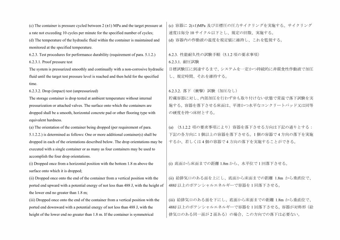
(c) The container is pressure cycled between 2 (±1) MPa and the target pressure at
a rate not exceeding 10 cycles per minute for the specified number of cycles;
(d) The temperature of the hydraulic fluid within the container is maintained and
monitored at the specified temperature.
(c) 容器に 2(±1)MPa 及び目標圧の圧力サイクリングを実施する。サイクリング
速度は毎分 10 サイクル以下とし、規定の回数、実施する。
(d) 容器内の作動液の温度を規定値に維持し、これを監視する。
6.2.3. Test procedures for performance durability (requirement of para. 5.1.2.) 6.2.3. 性能耐久性の試験手順(5.1.2 項の要求事項)
6.2.3.1. Proof pressure test
The system is pressurized smoothly and continually with a non-corrosive hydraulic
fluid until the target test pressure level is reached and then held for the specified
time.
6.2.3.1. 耐圧試験
目標試験圧に到達するまで、システムを一定かつ持続的に非腐食性作動液で加圧
し、規定時間、それを維持する。
6.2.3.2. Drop (impact) test (unpressurized)
The storage container is drop tested at ambient temperature without internal
pressurization or attached valves. The surface onto which the containers are
dropped shall be a smooth, horizontal concrete pad or other flooring type with
equivalent hardness.
6.2.3.2. 落下(衝撃)試験(加圧なし)
貯蔵容器に対し、内部加圧を行わず弁も取り付けない状態で常温で落下試験を実
施する。容器を落下させる床面は、平滑かつ水平なコンクリートパッド又は同等
の硬度を持つ床材とする。
(a) The orientation of the container being dropped (per requirement of para.
5.1.2.2.) is determined as follows: One or more additional container(s) shall be
dropped in each of the orientations described below. The drop orientations may be
executed with a single container or as many as four containers may be used to
accomplish the four drop orientations.
(i) Dropped once from a horizontal position with the bottom 1.8 m above the
surface onto which it is dropped;
(ii) Dropped once onto the end of the container from a vertical position with the
ported end upward with a potential energy of not less than 488 J, with the height of
the lower end no greater than 1.8 m;
(iii) Dropped once onto the end of the container from a vertical position with the
ported end downward with a potential energy of not less than 488 J, with the
height of the lower end no greater than 1.8 m. If the container is symmetrical
(a) (5.1.2.2 項の要求事項により)容器を落下させる方向は下記の通りとする:
下記の各方向に 1 個以上の容器を落下させる。1 個の容器で 4 方向の落下を実施
するか、若しくは 4 個の容器で 4 方向の落下を実施することができる。
(i) 底面から床面までの距離 1.8m から、水平位で 1 回落下させる。
(ii) 給排気口のある面を上にし、底面から床面までの距離 1.8m から垂直位で、
488J 以上のポテンシャルエネルギーで容器を 1 回落下させる。
(iii) 給排気口のある面を下にし、底面から床面までの距離 1.8m から垂直位で、
488J 以上のポテンシャルエネルギーで容器を 1 回落下させる。容器が対称形(給
排気口のある同一面が 2 面ある)の場合、この方向での落下は必要ない。
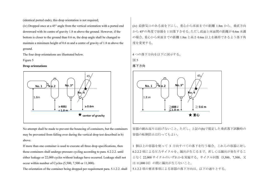
(identical ported ends), this drop orientation is not required;
(iv) Dropped once at a 45° angle from the vertical orientation with a ported end
downward with its centre of gravity 1.8 m above the ground. However, if the
bottom is closer to the ground than 0.6 m, the drop angle shall be changed to
maintain a minimum height of 0.6 m and a centre of gravity of 1.8 m above the
ground.
The four drop orientations are illustrated below.
(iv) 給排気口のある面を下にし、重心から床面までの距離 1.8m から、垂直方向
から 45°の角度で容器を 1 回落下させる。ただし底面と床面間の距離が 0.6m 未満
の場合、重心から床面までの距離 1.8m と高さ 0.6m 以上を維持できるよう落下角
度を変更する。
4 つの落下方向を以下に図示する。
Figure 5
Drop orientations
No attempt shall be made to prevent the bouncing of containers, but the containers
may be prevented from falling over during the vertical drop test described in b)
above.
If more than one container is used to execute all three drop specifications, then
those containers shall undergo pressure cycling according to para. 6.2.2.2. until
either leakage or 22,000 cycles without leakage have occurred. Leakage shall not
occur within number of Cycles (5,500, 7,500 or 11,000).
The orientation of the container being dropped per requirement para. 5.1.2.2. shall
図 5
落下方向
容器の跳ね返りは妨げないこと。ただし、上記の(b)で規定した垂直落下試験時の
容器の転倒防止は行ってもよい。
1 個以上の容器を使って 3 方向すべての落下を行う場合、これらの容器に対し
6.2.2.2 項による圧力サイクルを、漏出が生じるまで、若しくは漏出が発生するこ
となく 22,000 サイクルのいずれかを実施する。サイクル回数(5,500、7,500、又
は 11,000 回)の間に漏出が生じないこと。
5.1.2.2 項の要求事項による容器の落下方向は、以下の通りとする。
be identified as follows:
(a) If a single container was subjected to all four drop orientations, then the
container being dropped per requirement of para. 5.1.2.2. shall be dropped in all
four orientations;
(b) If more than one container is used to execute the four drop orientations, and if
all containers reach 22,000 cycles without leakage, then the orientation of the
container being dropped per requirement para. 5.1.2.2. is the 45o orientation (iv),
and that container shall then undergo further testing as specified in paragraph
5.1.2. ;
(c) If more than one container is used to execute the four drop orientations and if
any container does not reach 22,000 cycles without leakage, then the new
container shall be subjected to the drop orientation(s) that resulted in the lowest
number of cycles to leakage and then will undergo further testing as specified in
paragraph 5.1.2.
(a) 1 個の容器を使って 4 方向すべての落下を行った場合、5.1.2.2 の要求事項に従
い落下させる容器は、4 方向すべてに落下させる。
(b) 1 個以上の容器を使って 4 方向の落下を行った場合、かつすべての容器が漏出
を生じることなく 22,000 サイクルを達成した場合、5.1.2.2 項の要求事項に従い落
下させる容器の方向は、45°(iv)とし、容器に対して引き続き 5.1.2 項に規定され
た試験を実施する。
(c) 1 個以上の容器を使って 4 方向の落下を行った場合、かついずれかの容器が
22,000 サイクルを達成するまでに漏出を生じた場合、漏出が生じるまでのサイク
ル数が も少なかった方向で新しい容器を使用して落下を行い、引き続き 5.1.2
項に規定された試験を実施する。
6.2.3.3. Surface damage test (unpressurized)
The test proceeds in the following sequence:
6.2.3.3. 表面損傷試験(加圧なし)
試験は以下の順序で行う。
(a) Surface flaw generation: Two longitudinal saw cuts are made on the bottom
outer surface of the unpressurized horizontal storage container along the
cylindrical zone close to but not in the shoulder area. The first cut is at least
1.25 mm deep and 25 mm long toward the valve end of the container. The second
cut is at least 0.75 mm deep and 200 mm long toward the end of the container
opposite the valve;
(b) Pendulum impacts: The upper section of the horizontal storage container is
divided into five distinct (not overlapping) areas 100 mm in diameter each (see
Figure 6). After 12 hours preconditioning at – 40°C in an environmental chamber,
the centre of each of the five areas sustains the impact of a pendulum having a
pyramid with equilateral faces and square base, the summit and edges being
(a) 表面傷の生成:加圧していない水平位の容器の底面表面に、肩部ではなくそ
の近辺の円筒部分に沿って縦方向に 2 本のソーカットを入れる。1 本目の切り込
みは、容器の弁の向かって深さ 1.25mm 以上、長さ 25mm 以上のものとする。2
本目の切り込みは、容器の弁と反対方向に深さ 0.75mm 以上、長さ 200mm 以上
のものとする。
(b) 振り子式衝撃:水平位の貯蔵容器の上部を直径 100mm の別個の(重ならない)
5 つの部分に分割する。(図 6 を参照)環境室内において-40で 12 時間事前コ
ンディショニングを行い、5 つの部分の中央部それぞれに振り子による衝撃を加
える。振り子は等辺の面と四角形の土台から成るピラミッド構造を持ち、頂点と
端は半径 3mm の曲面とする。振り子の打撃中心は、ピラミッドの重心と一致す
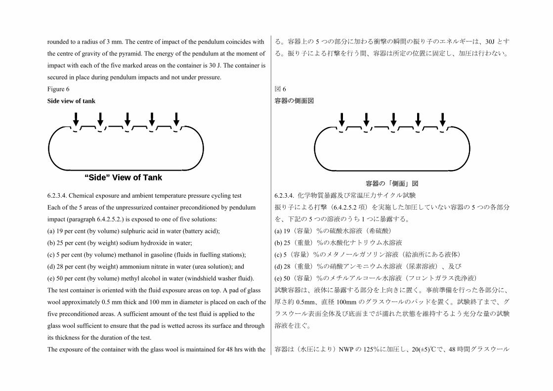
rounded to a radius of 3 mm. The centre of impact of the pendulum coincides with
the centre of gravity of the pyramid. The energy of the pendulum at the moment of
impact with each of the five marked areas on the container is 30 J. The container is
secured in place during pendulum impacts and not under pressure.
る。容器上の 5 つの部分に加わる衝撃の瞬間の振り子のエネルギーは、30J とす
る。振り子による打撃を行う間、容器は所定の位置に固定し、加圧は行わない。
Figure 6
Side view of tank
図 6
容器の側面図
容器の「側面」図
6.2.3.4. Chemical exposure and ambient temperature pressure cycling test
Each of the 5 areas of the unpressurized container preconditioned by pendulum
impact (paragraph 6.4.2.5.2.) is exposed to one of five solutions:
6.2.3.4. 化学物質暴露及び常温圧力サイクル試験
振り子による打撃(6.4.2.5.2 項)を実施した加圧していない容器の 5 つの各部分
を、下記の 5 つの溶液のうち 1 つに暴露する。
(a) 19 per cent (by volume) sulphuric acid in water (battery acid);
(b) 25 per cent (by weight) sodium hydroxide in water;
(c) 5 per cent (by volume) methanol in gasoline (fluids in fuelling stations);
(d) 28 per cent (by weight) ammonium nitrate in water (urea solution); and
(e) 50 per cent (by volume) methyl alcohol in water (windshield washer fluid).
The test container is oriented with the fluid exposure areas on top. A pad of glass
wool approximately 0.5 mm thick and 100 mm in diameter is placed on each of the
five preconditioned areas. A sufficient amount of the test fluid is applied to the
glass wool sufficient to ensure that the pad is wetted across its surface and through
its thickness for the duration of the test.
The exposure of the container with the glass wool is maintained for 48 hrs with the
(a) 19(容量)%の硫酸水溶液(希硫酸)
(b) 25(重量)%の水酸化ナトリウム水溶液
(c) 5(容量)%のメタノールガソリン溶液(給油所にある液体)
(d) 28(重量)%の硝酸アンモニウム水溶液(尿素溶液)、及び
(e) 50(容量)%のメチルアルコール水溶液(フロントガラス洗浄液)
試験容器は、液体に暴露する部分を上向きに置く。事前準備を行った各部分に、
厚さ約 0.5mm、直径 100mm のグラスウールのパッドを置く。試験終了まで、グ
ラスウール表面全体及び底面までが濡れた状態を維持するよう充分な量の試験
溶液を注ぐ。
容器は(水圧により)NWP の 125%に加圧し、20(±5)で、48 時間グラスウール
“Side” View of Tank“Side” View of Tank
container held at 125 per cent NWP (applied hydraulically) and 20 (±5) °C before
the container is subjected to further testing.
Pressure cycling is performed to the specified target pressures according to
paragraph 6.2.2.2. at 20 (±5)°C for the specified numbers of cycles. The glass wool
pads are removed and the container surface is rinsed with water the final 10 cycles
to specified final target pressure are conducted.
を暴露した後、次の試験を行う。
6.2.2.2 項に従い、20(±5)で、規定目標圧で規定回数の圧力サイクルを実施する。
グラスウールのパッドを取り除いて表面を水ですすぎ、規定の 終圧で 後の 10
サイクルを実施する。
6.2.3.5. Static pressure test (hydraulic)
The storage system is pressurized to the target pressure in a temperature-controlled
chamber. The temperature of the chamber and the non-corrosive fuelling fluid is
held at the target temperature within ±5°C for the specified duration.
6.2.3.5. 静圧試験(水圧)
温度制御された室内で貯蔵システムを目標圧に加圧する。室内の温度及び非腐
食性液体の温度は、規定された期間、目標温度の±5に維持する。
6.2.4. Test procedures for expected on-road performance (para. 5.1.3.)
(Pneumatic test procedures are provided; hydraulic test elements are described in
para. 6.3.2.)
6.2.4. 路上予定性能の試験手順(5.1.3 項)
(気圧試験手順を示す:水圧試験の内容は 6.3.2 項で規定する。)
6.2.4.1. Gas pressure cycling test (pneumatic)
At the onset of testing, the storage system is stabilized at the specified temperature,
relative humidity and fuel level for at least 24 hrs. The specified temperature and
relative humidity is maintained within the test environment throughout the
remainder of the test. (When required in the test specification, the system
temperature is stabilized at the external environmental temperature between
pressure cycles.) The storage system is pressure cycled between less than
2(+0/-1)MPa and the specified maximum pressure (±1MPa). If system controls
that are active in vehicle service prevent the pressure from dropping below a
specified pressure, the test cycles shall not go below that specified pressure. The
fill rate is controlled to a constant 3-minute pressure ramp rate, but with the fuel
flow not to exceed 60 g/s; the temperature of the hydrogen fuel dispensed to the
container is controlled to the specified temperature. However, the pressure ramp
rate should be decreased if the gas temperature in the container exceeds +85°C.
6.2.4.1. ガス圧サイクル試験(気圧)
試験の始めに、規定の温度、相対湿度、燃料量で貯蔵システムを 24 時間以上安
定させる。試験環境内は、試験終了まで規定の温度及び相対湿度を維持する。(試
験要件により要求される場合は、圧力サイクル間のシステム温度を外部の周囲温
度で安定させる。)
貯蔵システムに対し 2(+0/-1)MPa 未満と規定の 大圧力(±1MPa)で圧力サイク
ルを実施する。車両において規定圧以下に圧力が低下することを防止するシステ
ム制御が働いている場合試験サイクルは規定圧以下にしない。注入速度は、燃料
の流量が 60g/秒を超えないよう、一定の 3 分圧力ランプ速度に制御する。容器に
注入される水素燃料の温度は、規定温度に制御する。ただし、容器内のガス温度
が+85を超える場合、圧力ランプ速度を減少させること。燃料抜き取り速度は、
対象車両の 大燃料需要速度以上に制御する。圧力サイクルは規定された回数実
施する。車両が極端な内部温度を防止する装置及び/又は制御を使用している場
合、試験はこれらの装置及び/又は制御(若しくは同等の手段)を用いて実施す
The defuelling rate is controlled to greater than or equal to the intended vehicle’s
maximum fuel-demand rate. The specified number of pressure cycles is conducted.
If devices and/or controls are used in the intended vehicle application to prevent an
extreme internal temperature, the test may be conducted with these devices and/or
controls (or equivalent measures).
る。
6.2.4.2. Gas permeation test (pneumatic)
A storage system is fully filled with hydrogen gas at 115 per cent NWP (full fill
density equivalent to 100 per cent NWP at +15°C is 113 per cent NWP at +55°C)
and held at ≥ +55°C in a sealed container until steady-state permeation or 30
hours, whichever is longer. The total steady-state discharge rate due to leakage and
permeation from the storage system is measured.
6.2.4.2. ガス透過試験(気圧)
NWP の 115%(+15で NWP の 100%と同等の全充填密度は+55で NWP の
113%)で水素ガスを充填した貯蔵システムを、密閉容器内に≧+55で 定常透
過状態になるか若しくは 30 時間経過するか、いずれか長い方まで維持する。漏
出及び透過による貯蔵システムからの定常状態の総排出率を測定する。
6.2.4.3. Localized gas leak test (pneumatic)
A bubble test may be used to fulfil this requirement. The following procedure is
used when conducting the bubble test:
6.2.4.3. 局所的ガス漏出試験(気圧)
この要求事項を満たすため、発泡試験を実施してもよい。発泡試験を行う場合、
以下の手順を使用すること。
(a) The exhaust of the shutoff valve (and other internal connections to hydrogen
systems) shall be capped for this test (as the test is focused at external leakage).
At the discretion of the tester, the test article may be immersed in the leak-test
fluid or leak-test fluid applied to the test article when resting in open air. Bubbles
can vary greatly in size, depending on conditions. The tester estimates the gas
leakage based on the size and rate of bubble formation.
(b) Note: For a localized rate of 0.005 mg/sec (3.6 NmL/min), the resultant
allowable rate of bubble generation is about 2,030 bubbles per minute for a typical
bubble size of 1.5 mm in diameter. Even if much larger bubbles are formed, the
leak should be readily detectable. For an unusually large bubble size of 6 mm in
diameter, the allowable bubble rate would be approximately 32 bubbles per
minute.
(a) 当該試験において、(外部への漏出を検査する目的であることから)遮断弁
(及びその他の水素システムと内部接続されたもの)の排出口を塞ぐ。
試験装置により、被験試料を漏出試験で使用する液体に浸す、あるいは被験試料
が開放空気に置かれている場合は、この液体を試料に塗布してもよい。状況によ
り泡の大きさは大きく異なる。試験装置は、発泡の大きさ及び速度によりガス漏
出量を推定する。
(b) 注:局所的速度が 0.005mg/秒(3.6NmL/分)の場合、許容される発泡はほぼ
直径 1.5mm の大きさの泡であれば 1 分間あたり約 2,030 個である。これより大き
な泡が生成された場合でも、漏出は容易に検出できること。直径 6mm 以上の非
常に大きな泡が生成した場合、許容される泡の数は 1 分間あたり約 32 個とする。
6.2.5. Test procedures for service terminating performance in fire (para. 5.1.4.) 6.2.5. 火災時におけるサービス停止性能に関する試験手順(5.1.4 項)
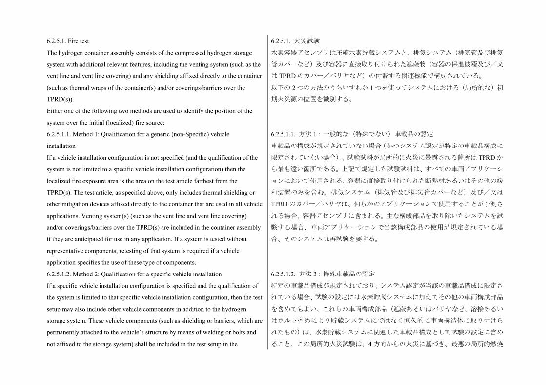
6.2.5.1. Fire test
The hydrogen container assembly consists of the compressed hydrogen storage
system with additional relevant features, including the venting system (such as the
vent line and vent line covering) and any shielding affixed directly to the container
(such as thermal wraps of the container(s) and/or coverings/barriers over the
TPRD(s)).
Either one of the following two methods are used to identify the position of the
system over the initial (localized) fire source:
6.2.5.1. 火災試験
水素容器アセンブリは圧縮水素貯蔵システムと、排気システム(排気管及び排気
管カバーなど)及び容器に直接取り付けられた遮蔽物(容器の保温被覆及び/又
は TPRD のカバー/バリヤなど)の付帯する関連機能で構成されている。
以下の 2 つの方法のうちいずれか 1 つを使ってシステムにおける(局所的な)初
期火災源の位置を識別する。
6.2.5.1.1. Method 1: Qualification for a generic (non-Specific) vehicle
installation
If a vehicle installation configuration is not specified (and the qualification of the
system is not limited to a specific vehicle installation configuration) then the
localized fire exposure area is the area on the test article farthest from the
TPRD(s). The test article, as specified above, only includes thermal shielding or
other mitigation devices affixed directly to the container that are used in all vehicle
applications. Venting system(s) (such as the vent line and vent line covering)
and/or coverings/barriers over the TPRD(s) are included in the container assembly
if they are anticipated for use in any application. If a system is tested without
representative components, retesting of that system is required if a vehicle
application specifies the use of these type of components.
6.2.5.1.1. 方法 1:一般的な(特殊でない)車載品の認定
車載品の構成が規定されていない場合(かつシステム認定が特定の車載品構成に
限定されていない場合)、試験試料が局所的に火災に暴露される箇所は TPRD か
ら も遠い箇所である。上記で規定した試験試料は、すべての車両アプリケーシ
ョンにおいて使用される、容器に直接取り付けられた断熱材あるいはその他の緩
和装置のみを含む。排気システム(排気管及び排気管カバーなど)及び/又は
TPRD のカバー/バリヤは、何らかのアプリケーションで使用することが予測さ
れる場合、容器アセンブリに含まれる。主な構成部品を取り除いたシステムを試
験する場合、車両アプリケーションで当該構成部品の使用が規定されている場
合、そのシステムは再試験を要する。
6.2.5.1.2. Method 2: Qualification for a specific vehicle installation
If a specific vehicle installation configuration is specified and the qualification of
the system is limited to that specific vehicle installation configuration, then the test
setup may also include other vehicle components in addition to the hydrogen
storage system. These vehicle components (such as shielding or barriers, which are
permanently attached to the vehicle’s structure by means of welding or bolts and
not affixed to the storage system) shall be included in the test setup in the
6.2.5.1.2. 方法 2:特殊車載品の認定
特定の車載品構成が規定されており、システム認定が当該の車載品構成に限定さ
れている場合、試験の設定には水素貯蔵システムに加えてその他の車両構成部品
を含めてもよい。これらの車両構成部品(遮蔽あるいはバリヤなど、溶接あるい
はボルト留めにより貯蔵システムにではなく恒久的に車両構造体に取り付けら
れたもの)は、水素貯蔵システムに関連した車載品構成として試験の設定に含め
ること。この局所的火災試験は、4 方向からの火災に基づき、 悪の局所的燃焼
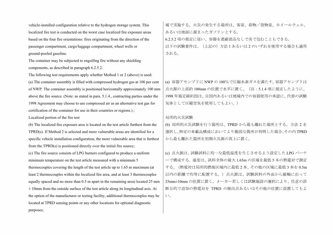
vehicle-installed configuration relative to the hydrogen storage system. This
localized fire test is conducted on the worst case localized fire exposure areas
based on the four fire orientations: fires originating from the direction of the
passenger compartment, cargo/luggage compartment, wheel wells or
ground-pooled gasoline.
The container may be subjected to engulfing fire without any shielding
components, as described in paragraph 6.2.5.2.
The following test requirements apply whether Method 1 or 2 (above) is used:
域で実施する。火災の発生する場所は、客室、荷物/貨物室、ホイールウェル、
あるいは地面に溜まったガソリンとする。
6.2.5.2 項の規定に従い、容器を遮蔽部品なしで炎で包むこともできる。
以下の試験要件は、(上記の)方法 1 あるいは 2 のいずれを使用する場合も適用
される。
(a) The container assembly is filled with compressed hydrogen gas at 100 per cent
of NWP. The container assembly is positioned horizontally approximately 100 mm
above the fire source. (Note: as stated in para. 5.1.4., contracting parties under the
1998 Agreement may choose to use compressed air as an alternative test gas for
certification of the container for use in their countries or regions.) ;
Localized portion of the fire test
(a) 容器アセンブリに NWP の 100%で圧縮水素ガスを満たす。容器アセンブリは
点火源の上部約 100mm の位置で水平に置く。(注:5.1.4 項に規定したように、
1998 年協定締約国は、自国内あるいは地域内での容器使用の承認に、代替の試験
気体として圧縮空気を使用してもよい。)
局所的火災試験
(b) The localized fire exposure area is located on the test article furthest from the
TPRD(s). If Method 2 is selected and more vulnerable areas are identified for a
specific vehicle installation configuration, the more vulnerable area that is furthest
from the TPRD(s) is positioned directly over the initial fire source;
(b) 局所的火災試験を行う箇所は、TPRD から も離れた場所とする。方法 2 を
選択し、特定の車載品構成においてより脆弱な箇所が判明した場合、その内 TPRD
から も離れた箇所を初期火災源の真上に置く。
(c) The fire source consists of LPG burners configured to produce a uniform
minimum temperature on the test article measured with a minimum 5
thermocouples covering the length of the test article up to 1.65 m maximum (at
least 2 thermocouples within the localized fire area, and at least 3 thermocouples
equally spaced and no more than 0.5 m apart in the remaining area) located 25 mm
± 10mm from the outside surface of the test article along its longitudinal axis. At
the option of the manufacturer or testing facility, additional thermocouples may be
located at TPRD sensing points or any other locations for optional diagnostic
purposes;
(c) 点火源は、試験試料に均一な 低温度を生じさせるよう設定した LPG バーナ
ーで構成する。温度は、試料全体の 大 1.65m の区域を 低 5 本の熱電対で測定
する。(熱電対は局所的燃焼区域内に 低 2 本、その他の区域に 低 3 本を 0.5m
以内の距離で均等に配置する。)点火源は、試験試料の外面から縦軸に沿って
25mm±10mm の位置に置く。メーカー若しくは試験施設の選択により、任意の診
断目的で追加の熱電対を TPRD の検出点あるいはその他の位置に設置してもよ
い。
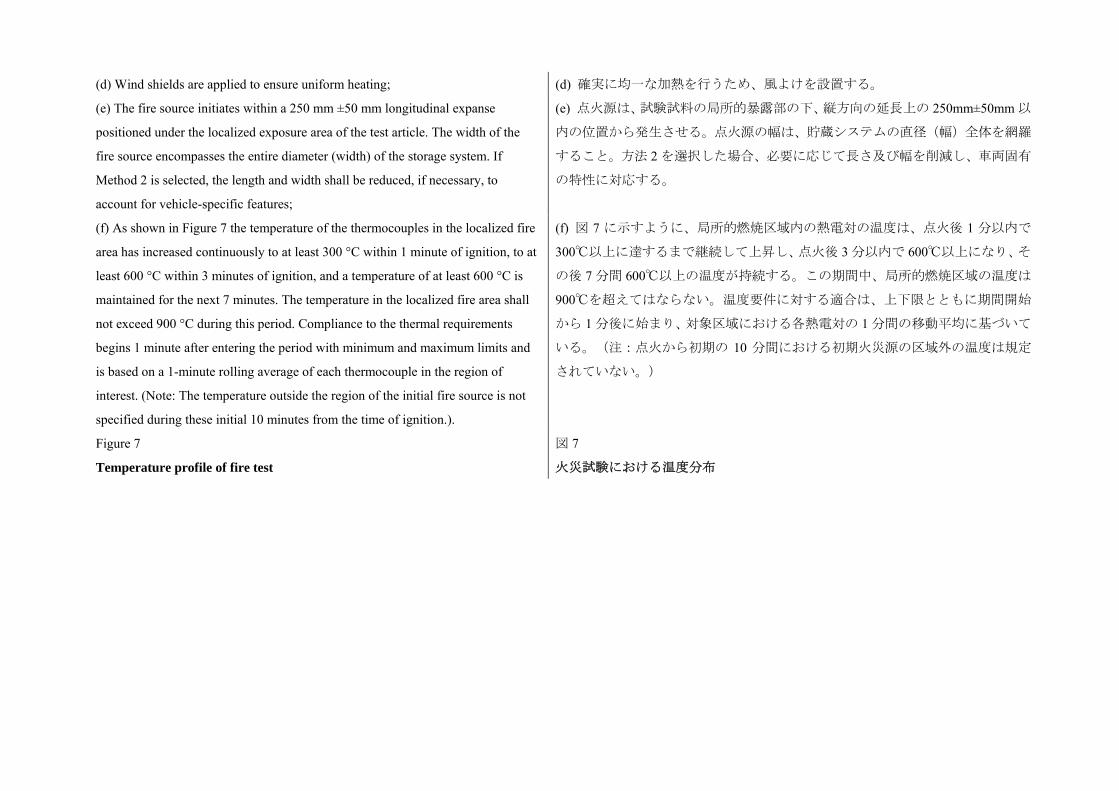
(d) Wind shields are applied to ensure uniform heating; (d) 確実に均一な加熱を行うため、風よけを設置する。
(e) The fire source initiates within a 250 mm ±50 mm longitudinal expanse
positioned under the localized exposure area of the test article. The width of the
fire source encompasses the entire diameter (width) of the storage system. If
Method 2 is selected, the length and width shall be reduced, if necessary, to
account for vehicle-specific features;
(e) 点火源は、試験試料の局所的暴露部の下、縦方向の延長上の 250mm±50mm 以
内の位置から発生させる。点火源の幅は、貯蔵システムの直径(幅)全体を網羅
すること。方法 2 を選択した場合、必要に応じて長さ及び幅を削減し、車両固有
の特性に対応する。
(f) As shown in Figure 7 the temperature of the thermocouples in the localized fire
area has increased continuously to at least 300 °C within 1 minute of ignition, to at
least 600 °C within 3 minutes of ignition, and a temperature of at least 600 °C is
maintained for the next 7 minutes. The temperature in the localized fire area shall
not exceed 900 °C during this period. Compliance to the thermal requirements
begins 1 minute after entering the period with minimum and maximum limits and
is based on a 1-minute rolling average of each thermocouple in the region of
interest. (Note: The temperature outside the region of the initial fire source is not
specified during these initial 10 minutes from the time of ignition.).
(f) 図 7 に示すように、局所的燃焼区域内の熱電対の温度は、点火後 1 分以内で
300以上に達するまで継続して上昇し、点火後 3 分以内で 600以上になり、そ
の後 7 分間 600以上の温度が持続する。この期間中、局所的燃焼区域の温度は
900を超えてはならない。温度要件に対する適合は、上下限とともに期間開始
から 1 分後に始まり、対象区域における各熱電対の 1 分間の移動平均に基づいて
いる。(注:点火から初期の 10 分間における初期火災源の区域外の温度は規定
されていない。)
Figure 7
Temperature profile of fire test
図 7
火災試験における温度分布
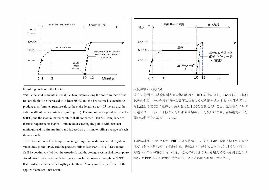
Engulfing portion of the fire test
Within the next 2-minute interval, the temperature along the entire surface of the
test article shall be increased to at least 800°C and the fire source is extended to
produce a uniform temperature along the entire length up to 1.65 meters and the
entire width of the test article (engulfing fire). The minimum temperature is held at
800°C, and the maximum temperature shall not exceed 1100°C. Compliance to
thermal requirements begins 1 minute after entering the period with constant
minimum and maximum limits and is based on a 1-minute rolling average of each
thermocouple.
The test article is held at temperature (engulfing fire condition) until the system
vents through the TPRD and the pressure falls to less than 1 MPa. The venting
shall be continuous (without interruption), and the storage system shall not rupture.
An additional release through leakage (not including release through the TPRD)
that results in a flame with length greater than 0.5 m beyond the perimeter of the
applied flame shall not occur.
火災試験の火災部分
続く 2 分間で、試験試料表面全体の温度が 800以上に達し、1.65m 以下の試験
試料の全長、かつ全幅が均一な温度になるよう点火源を拡大する(全体火災)。
低温度は 800に維持し、 大温度は 1100を超えないこと。温度要件に対す
る適合は、一定の上下限とともに期間開始から 1 分後に始まり、各熱電対の 1 分
間の移動平均に基づいている。
試験試料は、システムが TPRD により排気し、圧力が 1MPa 未満に低下するまで
温度(全体火災状態)を維持する。排気は(中断することなく)継続して行い、
貯蔵システムが破裂しないこと。点火点の周囲 0.5m を超えて発火を引き起こす
漏出(TPRD からの放出は含まない)による放出が発生しないこと。
1
600o C
800o C
Localized Fire Exposure Engulfing Fire
Minutes1210
300o C
3
MinTemp
Localized Area
Engulfing Region Outside Localized Area (burner
ramp rate)
Ignite Main
Burner
0
局所的火災暴露 全体火災 温度
局所
局所外の全体火災
区域(バーナーラ
ンプ速度)
主バーナー点
火
分
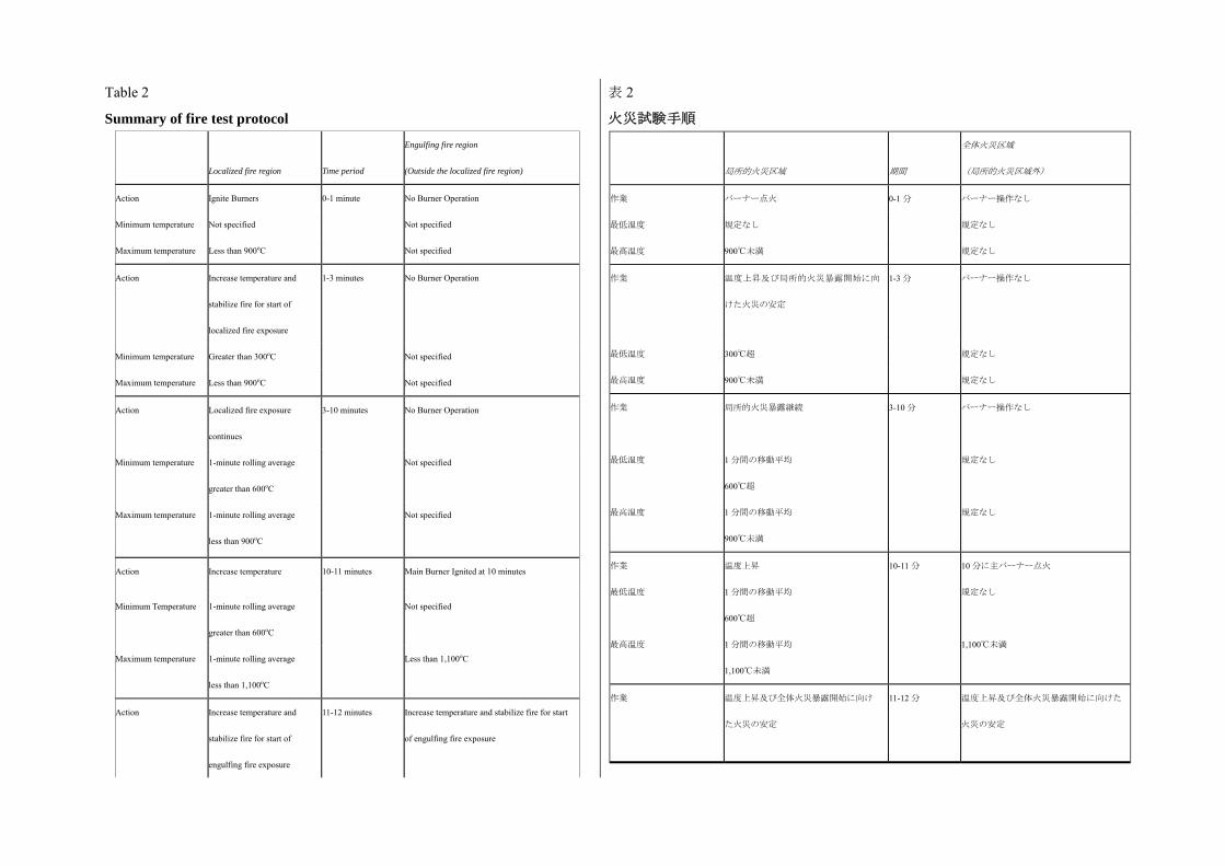
Table 2
Summary of fire test protocol
Localized fire region Time period
Engulfing fire region
(Outside the localized fire region)
Action Ignite Burners 0-1 minute No Burner Operation
Minimum temperature Not specified Not specified
Maximum temperature Less than 900oC Not specified
Action Increase temperature and
stabilize fire for start of
localized fire exposure
1-3 minutes No Burner Operation
Minimum temperature Greater than 300oC Not specified
Maximum temperature Less than 900oC Not specified
Action
Localized fire exposure
continues
3-10 minutes No Burner Operation
Minimum temperature 1-minute rolling average
greater than 600oC
Not specified
Maximum temperature 1-minute rolling average
less than 900oC
Not specified
Action Increase temperature 10-11 minutes Main Burner Ignited at 10 minutes
Minimum Temperature 1-minute rolling average
greater than 600oC
Not specified
Maximum temperature 1-minute rolling average
less than 1,100oC
Less than 1,100oC
Action Increase temperature and
stabilize fire for start of
engulfing fire exposure
11-12 minutes Increase temperature and stabilize fire for start
of engulfing fire exposure
表 2
火災試験手順
局所的火災区域 期間
全体火災区域
(局所的火災区域外)
作業 バーナー点火 0-1 分 バーナー操作なし
低温度 規定なし 規定なし
高温度 900未満 規定なし
作業 温度上昇及び局所的火災暴露開始に向
けた火災の安定
1-3 分 バーナー操作なし
低温度 300超 規定なし
高温度 900未満 規定なし
作業
低温度
高温度
局所的火災暴露継続
1 分間の移動平均
600超
1 分間の移動平均
900未満
3-10 分 バーナー操作なし
規定なし
規定なし
作業
低温度
高温度
温度上昇
1 分間の移動平均
600超
1 分間の移動平均
1,100未満
10-11 分 10 分に主バーナー点火
規定なし
1,100未満
作業
温度上昇及び全体火災暴露開始に向け
た火災の安定
11-12 分 温度上昇及び全体火災暴露開始に向けた
火災の安定
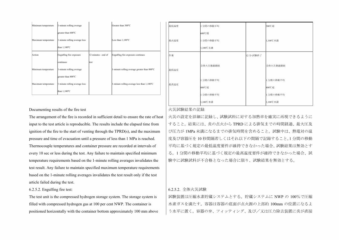
Minimum temperature 1-minute rolling average
greater than 600oC
Greater than 300oC
Maximum temperature 1 minute rolling average less
than 1,100oC
Less than 1,100oC
Action Engulfing fire exposure
continues
12 minutes - end of
test
Engulfing fire exposure continues
Minimum temperature 1-minute rolling average
greater than 800oC
1-minute rolling average greater than 800oC
Maximum temperature 1 minute rolling average less
than 1,100oC
1-minute rolling average less than 1,100oC
低温度
高温度
1 分間の移動平均
600超
1 分間の移動平均
1,100未満
300超
1,100未満
作業
低温度
高温度
全体火災暴露継続
1 分間の移動平均
800超
1 分間の移動平均
1,100未満
12 分-試験終了
全体火災暴露継続
1 分間の移動平均
800超
1 分間の移動平均
1,100未満
Documenting results of the fire test
The arrangement of the fire is recorded in sufficient detail to ensure the rate of heat
input to the test article is reproducible. The results include the elapsed time from
ignition of the fire to the start of venting through the TPRD(s), and the maximum
pressure and time of evacuation until a pressure of less than 1 MPa is reached.
Thermocouple temperatures and container pressure are recorded at intervals of
every 10 sec or less during the test. Any failure to maintain specified minimum
temperature requirements based on the 1-minute rolling averages invalidates the
test result. Any failure to maintain specified maximum temperature requirements
based on the 1-minute rolling averages invalidates the test result only if the test
article failed during the test.
火災試験結果の記録
火災の設定を詳細に記録し、試験試料に対する加熱率を確実に再現できるように
すること。結果には、炎の点火から TPRD による排気までの時間経過、 大圧及
び圧力が 1MPa 未満になるまでの排気時間を含めること。試験中は、熱電対の温
度及び容器圧を 10 秒間隔若しくはそれ以下の間隔で記録すること。1 分間の移動
平均に基づく規定の 低温度要件が維持できなかった場合、試験結果は無効とす
る。1 分間の移動平均に基づく規定の 高温度要件が維持できなかった場合、試
験中に試験試料が不合格となった場合に限り、試験結果を無効とする。
6.2.5.2. Engulfing fire test:
The test unit is the compressed hydrogen storage system. The storage system is
filled with compressed hydrogen gas at 100 per cent NWP. The container is
positioned horizontally with the container bottom approximately 100 mm above
6.2.5.2. 全体火災試験
試験装置は圧縮水素貯蔵システムとする。貯蔵システムに NWP の 100%で圧縮
水素ガスを満たす。容器は容器の底面が点火源の上部約 100mm の位置になるよ
う水平に置く。容器の弁、フィッティング、及び/又は圧力除去装置に炎が直接
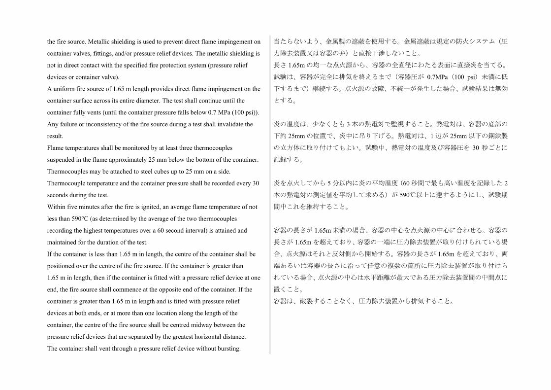
the fire source. Metallic shielding is used to prevent direct flame impingement on
container valves, fittings, and/or pressure relief devices. The metallic shielding is
not in direct contact with the specified fire protection system (pressure relief
devices or container valve).
A uniform fire source of 1.65 m length provides direct flame impingement on the
container surface across its entire diameter. The test shall continue until the
container fully vents (until the container pressure falls below 0.7 MPa (100 psi)).
Any failure or inconsistency of the fire source during a test shall invalidate the
result.
Flame temperatures shall be monitored by at least three thermocouples
suspended in the flame approximately 25 mm below the bottom of the container.
Thermocouples may be attached to steel cubes up to 25 mm on a side.
Thermocouple temperature and the container pressure shall be recorded every 30
seconds during the test.
Within five minutes after the fire is ignited, an average flame temperature of not
less than 590°C (as determined by the average of the two thermocouples
recording the highest temperatures over a 60 second interval) is attained and
maintained for the duration of the test.
If the container is less than 1.65 m in length, the centre of the container shall be
positioned over the centre of the fire source. If the container is greater than
1.65 m in length, then if the container is fitted with a pressure relief device at one
end, the fire source shall commence at the opposite end of the container. If the
container is greater than 1.65 m in length and is fitted with pressure relief
devices at both ends, or at more than one location along the length of the
container, the centre of the fire source shall be centred midway between the
pressure relief devices that are separated by the greatest horizontal distance.
The container shall vent through a pressure relief device without bursting.
当たらないよう、金属製の遮蔽を使用する。金属遮蔽は規定の防火システム(圧
力除去装置又は容器の弁)と直接干渉しないこと。
長さ 1.65m の均一な点火源から、容器の全直径にわたる表面に直接炎を当てる。
試験は、容器が完全に排気を終えるまで(容器圧が 0.7MPa(100 psi)未満に低
下するまで)継続する。点火源の故障、不統一が発生した場合、試験結果は無効
とする。
炎の温度は、少なくとも 3 本の熱電対で監視すること。熱電対は、容器の底部の
下約 25mm の位置で、炎中に吊り下げる。熱電対は、1 辺が 25mm 以下の鋼鉄製
の立方体に取り付けてもよい。試験中、熱電対の温度及び容器圧を 30 秒ごとに
記録する。
炎を点火してから 5 分以内に炎の平均温度(60 秒間で も高い温度を記録した 2
本の熱電対の測定値を平均して求める)が 590以上に達するようにし、試験期
間中これを維持すること。
容器の長さが 1.65m 未満の場合、容器の中心を点火源の中心に合わせる。容器の
長さが 1.65m を超えており、容器の一端に圧力除去装置が取り付けられている場
合、点火源はそれと反対側から開始する。容器の長さが 1.65m を超えており、両
端あるいは容器の長さに沿って任意の複数の箇所に圧力除去装置が取り付けら
れている場合、点火源の中心は水平距離が 大である圧力除去装置間の中間点に
置くこと。
容器は、破裂することなく、圧力除去装置から排気すること。
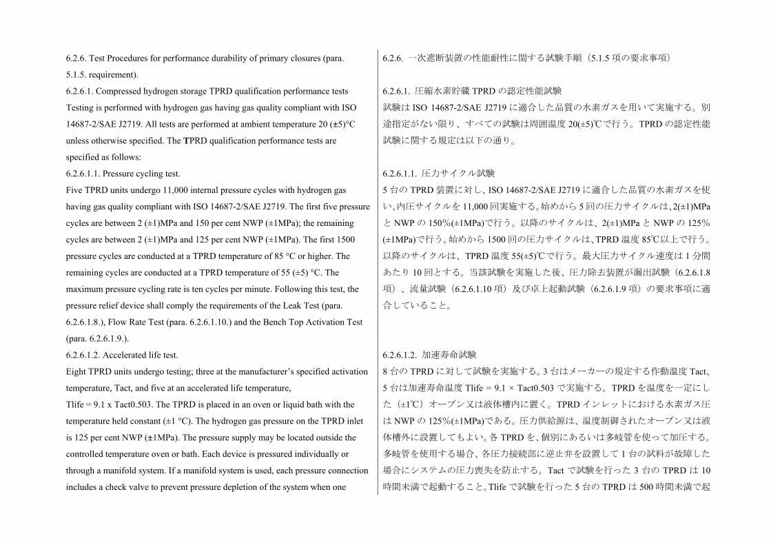
6.2.6. Test Procedures for performance durability of primary closures (para.
5.1.5. requirement).
6.2.6. 一次遮断装置の性能耐性に関する試験手順(5.1.5 項の要求事項)
6.2.6.1. Compressed hydrogen storage TPRD qualification performance tests
Testing is performed with hydrogen gas having gas quality compliant with ISO
14687-2/SAE J2719. All tests are performed at ambient temperature 20 (±5)°C
unless otherwise specified. The TPRD qualification performance tests are
specified as follows:
6.2.6.1. 圧縮水素貯蔵 TPRD の認定性能試験
試験は ISO 14687-2/SAE J2719 に適合した品質の水素ガスを用いて実施する。別
途指定がない限り、すべての試験は周囲温度 20(±5)で行う。TPRD の認定性能
試験に関する規定は以下の通り。
6.2.6.1.1. Pressure cycling test.
Five TPRD units undergo 11,000 internal pressure cycles with hydrogen gas
having gas quality compliant with ISO 14687-2/SAE J2719. The first five pressure
cycles are between 2 (±1)MPa and 150 per cent NWP (±1MPa); the remaining
cycles are between 2 (±1)MPa and 125 per cent NWP (±1MPa). The first 1500
pressure cycles are conducted at a TPRD temperature of 85 °C or higher. The
remaining cycles are conducted at a TPRD temperature of 55 (±5) °C. The
maximum pressure cycling rate is ten cycles per minute. Following this test, the
pressure relief device shall comply the requirements of the Leak Test (para.
6.2.6.1.8.), Flow Rate Test (para. 6.2.6.1.10.) and the Bench Top Activation Test
(para. 6.2.6.1.9.).
6.2.6.1.1. 圧力サイクル試験
5 台の TPRD 装置に対し、ISO 14687-2/SAE J2719 に適合した品質の水素ガスを使
い、内圧サイクルを 11,000 回実施する。始めから 5 回の圧力サイクルは、2(±1)MPa
と NWP の 150%(±1MPa)で行う。以降のサイクルは、2(±1)MPa と NWP の 125%
(±1MPa)で行う。始めから 1500 回の圧力サイクルは、TPRD 温度 85以上で行う。
以降のサイクルは、TPRD 温度 55(±5)で行う。 大圧力サイクル速度は 1 分間
あたり 10 回とする。当該試験を実施した後、圧力除去装置が漏出試験(6.2.6.1.8
項)、流量試験(6.2.6.1.10 項)及び卓上起動試験(6.2.6.1.9 項)の要求事項に適
合していること。
6.2.6.1.2. Accelerated life test.
Eight TPRD units undergo testing; three at the manufacturer’s specified activation
temperature, Tact, and five at an accelerated life temperature,
Tlife = 9.1 x Tact0.503. The TPRD is placed in an oven or liquid bath with the
temperature held constant (±1 °C). The hydrogen gas pressure on the TPRD inlet
is 125 per cent NWP (±1MPa). The pressure supply may be located outside the
controlled temperature oven or bath. Each device is pressured individually or
through a manifold system. If a manifold system is used, each pressure connection
includes a check valve to prevent pressure depletion of the system when one
6.2.6.1.2. 加速寿命試験
8 台の TPRD に対して試験を実施する。3 台はメーカーの規定する作動温度 Tact、
5 台は加速寿命温度 Tlife = 9.1 × Tact0.503 で実施する。TPRD を温度を一定にし
た(±1)オーブン又は液体槽内に置く。TPRD インレットにおける水素ガス圧
は NWP の 125%(±1MPa)である。圧力供給源は、温度制御されたオーブン又は液
体槽外に設置してもよい。各 TPRD を、個別にあるいは多岐管を使って加圧する。
多岐管を使用する場合、各圧力接続部に逆止弁を設置して 1 台の試料が故障した
場合にシステムの圧力喪失を防止する。Tact で試験を行った 3 台の TPRD は 10
時間未満で起動すること。Tlife で試験を行った 5 台の TPRD は 500 時間未満で起
specimen fails. The three TPRDs tested at tact shall activate in less than ten hours.
The five TPRDs tested at Tlife shall not activate in less than 500 hours.
動しないこと。
6.2.6.1.3. Temperature cycling test 6.2.6.1.3. 温度サイクル試験
(a) An unpressurized TPRD is placed in a liquid bath maintained at -40°C or lower
at least two hours. The TPRD is transferred to a liquid bath maintained at 85 °C or
higher within five minutes, and maintained at that temperature at least two hours.
The TPRD is transferred to a liquid bath maintained at -40 °C or lower within five
minutes;
(a) 加圧されていないTPRDを-40以下に保たれた液体槽内に2時間以上置く。
5 分以内に TPRD を 85以上に保たれた液体槽に移し、その温度で 2 時間以上置
く。5 分以内に TPRD を-40以下に保たれた液体槽内に移す。
(b) Step (a) is repeated until 15 thermal cycles have been achieved; (b) 手順(a)を温度サイクルが 15 回に達するまで繰り返す。
(c) With the TPRD conditioned for a minimum of two hours in the -40°C or lower
liquid bath, the internal pressure of the TPRD is cycled with hydrogen gas between
2MPa (+1/-0MPa) and 80 per cent NWP (+2/-0MPa) for 100 cycles while the
liquid bath is maintained at – 40 °C or lower;
(c) 温度-40以下の液体槽に 2 時間以上置いた TPRD に対し、液体槽温度を
-40以下に維持しながら、水素ガスを使って、2MPa(+1/-0MPa)と NWP の
80%(+2/-0MPa)の内圧サイクルを 100 回実施する。
(d) Following the thermal and pressure cycling, the pressure relief device shall
comply with the requirements of the Leak Test (para. 6.2.6.1.8.), except that the
Leak Test shall be conducted at -40 °C (+5/-0°C). After the Leak Test, the TPRD
shall comply with the requirements of the Bench Top Activation Test (para.
6.2.6.1.9.) and then the Flow Rate Test (para. 6.2.6.1.10.).
(d) 温度サイクル及び圧力サイクルを実施した後、圧力除去装置が漏出試験
(6.2.6.1.8 項)の要求事項に適合していること。ただし、漏出試験は、-40
(+5/-0)で実施する。漏出試験を実施した後、TPRD が卓上起動試験(6.2.6.1.9
項)さらには流量試験(6.2.6.1.10 項)の要求事項に適合していること。
6.2.6.1.4. Salt corrosion resistance test
Two TPRD units are tested. Any non-permanent outlet caps are removed. Each
TPRD unit is installed in a test fixture in accordance with the manufacturer’s
recommended procedure so that external exposure is consistent with realistic
installation. Each unit is exposed for 500 hours to a salt spray (fog) test as
specified in ASTM B117 (Standard Practice for Operating Salt Spray (Fog)
Apparatus) except that in the test of one unit, the pH of the salt solution shall be
adjusted to 4.0 ± 0.2 by the addition of sulphuric acid and nitric acid in a 2:1 ratio,
and in the test of the other unit, the pH of the salt solution shall be adjusted to 10.0
6.2.6.1.4. 耐塩腐食試験
2 台の TPRD 装置を試験する。取り外し可能なアウトレットキャップは取り除く。
各 TPRD はメーカーの推奨する手順に従い、実際の取り付け時と同じ外部露出と
なるよう試験装置に取り付ける。各装置は ASTM B117(塩水噴霧(霧)装置操作の
標準実施要領)で規定された塩水噴霧試験に 500 時間露出する。ただし一方の装
置の試験において、塩水に硫酸と硝酸を 2:1 の比率で加えての塩水の pH を
4.0±0.2 に調整する。さらに、もう一方の装置の試験において、塩水に水酸化ナ
トリウムを加えて塩水の pH を 10.0±0.2 に調整する。霧室内の温度は 30-35°C に
維持する。
± 0.2 by the addition of sodium hydroxide. The temperature within the fog
chamber is maintained at 30-35°C).
Following these tests, each pressure relief device shall comply with the
requirements of the leak test (para. 6.2.6.1.8.), Flow Rate Test (para. 6.2.6.1.10.)
and bench top activation test (para. 6.2.6.1.9.).
当該試験を実施した後、各圧力除去装置が漏出試験(6.2.6.1.8 項)、流量試験
(6.2.6.1.10 項)及び卓上起動試験(6.2.6.1.9 項)の要求事項に適合していること。
6.2.6.1.5. Vehicle environment test
Resistance to degradation by external exposure to automotive fluids is determined
by the following test:
6.2.6.1.5. 車両環境試験
自動車関連液体への外部暴露による耐劣化性は、以下の試験により評価する。
(a) The inlet and outlet connections of the TPRD are connected or capped in
accordance with the manufacturers installation instructions. The external surfaces
of the TPRD are exposed for 24 hours at 20 (±5) °C to each of the following
fluids:
(i) Sulphuric acid - 19 per cent solution by volume in water;
(ii) Sodium hydroxide - 25 per cent solution by weight in water;
(iii) Ammonium nitrate - 28 per cent by weight in water; and
(iv) Windshield washer fluid (50 per cent by volume methyl alcohol and water).
The fluids are replenished as needed to ensure complete exposure for the
duration of the test. A distinct test is performed with each of the fluids. One
component may be used for exposure to all of the fluids in sequence.
(a) TPRD のインレット及びアウトレット接続は、メーカーの取り付け指示に従
い、接続するか若しくはキャップを取り付ける。TPRD の外表面を以下の各液体
に 20(±5)で 24 時間暴露する。
(i) 19 容量%の硫酸水溶液
(ii) 25 重量%の水酸化ナトリウム水溶液
(iii) 28 重量%の硝酸アンモニウム水溶液、及び
(iv) フロントガラス洗浄液(50 容量%のメチルアルコール水溶液)
各液体は、試験期間中、完全かく確実な暴露状態を維持するため、必要に応じて
補給する。各液体について個別に試験を行う。1 台の構成部品に対し、すべての
液体を順に暴露してもよい。
(b) After exposure to each fluid, the component is wiped off and rinsed with water; (b) 各溶液に暴露した後、当該構成部品を拭き取り、水ですすぐ。
(c) The component shall not show signs of physical degradation that could impair
the function of the component, specifically: cracking, softening, or swelling.
Cosmetic changes such as pitting or staining are not failures. At the conclusion of
all exposures, the unit(s) shall comply with the requirements of the Leak Test
(para. 6.2.6.1.8.), Flow Rate Test (para. 6.2.6.1.10.) and Bench Top Activation test
(para. 6.2.6.1.9.).
(c) 構成部品は、その機能を損なうような物理的劣化、特に割れ、軟化、膨張な
どの痕跡がないこと。孔食、退色などの表面的変化は不合格としない。すべての
暴露が終了した後、各装置が漏出試験(6.2.6.1.8 項)、流量試験(6.2.6.1.10 項)
及び卓上起動試験(6.2.6.1.9 項)の要求事項に適合していること。
6.2.6.1.6. Stress corrosion cracking test. 6.2.6.1.6. 応力腐食割れ試験
For TPRDs containing components made of a copper-based alloy (e.g. brass), one
TPRD unit is tested. All copper alloy components exposed to the atmosphere shall
be degreased and then continuously exposed for ten days to a moist ammonia-air
mixture maintained in a glass chamber having a glass cover.
Aqueous ammonia having a specific gravity of 0.94 is maintained at the bottom of
the glass chamber below the sample at a concentration of at least 20 ml per litre of
chamber volume. The sample is positioned 35 (±5) mm above the aqueous
ammonia solution and supported in an inert tray. The moist ammonia-air mixture
is maintained at atmospheric pressure at 35 (±5) °C. Copper-based alloy
components shall not exhibit cracking or delaminating due to this test.
銅基合金(例、真ちゅう)製の構成部品を含む TPRD は、1 台の TPRD について
試験を実施する。大気に暴露されたすべての銅合金製の構成部品を脱脂し、ガラ
スカバー付きのガラス試験容器内で湿気を含む空気とアンモニアの混合気体に
10 日間連続して暴露する。
試験容器の容積の少なくとも 1 リットルあたり 20ml の濃度及び比重 0.94 のアン
モニア水をガラス試験容器内の試料の下の底部に入れる。試料はアンモニア水溶
液の上 35(±5)mm の位置に、固定された皿の上に置く。空気とアンモニアの湿気
を含む混合気体を大気圧で 35(±5)に維持する。この試験により、銅基合金製の
構成部品に割れ又は剥離が生じないこと。
6.2.6.1.7. Drop and vibration test 6.2.6.1.7. 落下及び振動試験
(a) Six TPRD units are dropped from a height of 2 m at ambient temperature (20 ±
5oC) onto a smooth concrete surface. Each sample is allowed to bounce on the
concrete surface after the initial impact. One unit is dropped in six orientations
(opposing directions of 3 orthogonal axes: vertical, lateral and longitudinal). If
each of the six dropped samples does not show visible exterior damage that
indicates that the part is unsuitable for use, it shall proceed to step (b);
(a) 6 台の TPRD を常温(20±5)で 2m の高さから、平滑なコンクリート面上に
落下させる。試料は 初の衝突の後、コンクリート面で跳ね返ってもよい。1 台
の装置を 6 方向(上下、左右、前後の 3 本の直交軸とその反対方向)で落下させ
る。落下させた 6 台の各試料に、使用に適さないことを示す外部損傷が見られな
い場合、手順(b)へ進む。
(b) Each of the six TPRD units dropped in step (a) and one additional unit not
subjected to a drop are mounted in a test fixture in accordance with manufacturer’s
installation instructions and vibrated 30 minutes along each of the three orthogonal
axes (vertical, lateral and longitudinal) at the most severe resonant frequency for
each axis. The most severe resonant frequencies are determined using an
acceleration of 1.5 g and sweeping through a sinusoidal frequency range of 10 to
500 Hz within 10 minutes. The resonance frequency is identified by a pronounced
increase in vibration amplitude. If the resonance frequency is not found in this
range, the test shall be conducted at 40 Hz. Following this test, each sample shall
not show visible exterior damage that indicates that the part is unsuitable for use. It
(b) 手順(a)で落下させた 6 台の各 TPRD 装置と、落下させていない追加の 1 台を
メーカーの取り付け指示に従って試験装置に取り付け、直交軸方向(上下、左右、
前後)に、それぞれ 大の共振周波数で 30 分間振動を与える。 大の共振周波
数は、加速度 1.5g を使い、10 から 500Hz の範囲の正弦波周波数を 10 分以内で掃
引して求める。共振周波数は振動幅の顕著な増加により識別される。この範囲内
で共振数が見つからない場合、試験は 40Hz で実施する。試験後、各試料に、使
用に適さないことを示す外部損傷が見られないこと。その後、各装置が漏出試験
(6.2.6.1.8 項)、流量試験(6.2.6.1.10 項)及び卓上起動試験(6.2.6.1.9 項)の要
求事項に適合していること。
shall subsequently comply with the requirements of the Leak Test (para.
6.2.6.1.8.), Flow Rate Test (para. 6.2.6.1.10.) and Bench Top Activation Test
(para. 6.2.6.1.9.)
6.2.6.1.8. Leak test
A TPRD that has not undergone previous testing is tested at ambient, high and low
temperatures without being subjected to other design qualification tests. The unit is
held for one hour at each temperature and test pressure before testing. The three
temperature test conditions are:
6.2.6.1.8. 漏出試験
試験を行っていない TPRD に対し常温、高温、低温で、他の設計承認試験を行う
ことなく試験を実施する。当該装置を 1 時間、各温度及び試験圧に維持し、その
後試験を実施する。温度試験の 3 つの条件は以下の通り。
(a) Ambient temperature: condition the unit at 20 (±5) °C; test at 5 per cent NWP
(+0/-2MPa) and 150 per cent NWP (+2/-0MPa) ;
(b) High temperature: condition the unit at 85°C or higher; test at 5 per cent NWP
(+0/-2MPa) and 150 per cent NWP (+2/-0MPa) ;
(c) Low temperature: condition the unit at -40°C or lower; test at 5 per cent NWP
(+0/-2MPa) and 100 per cent NWP (+2/-0MPa).
Additional units undergo leak testing as specified in other tests in para. 6.2.6.1.
with uninterrupted exposure at the temperature specified in those tests.
At all specified test temperatures, the unit is conditioned for one minute by
immersion in a temperature controlled fluid (or equivalent method). If no bubbles
are observed for the specified time period, the sample passes the test. If bubbles
are detected, the leak rate is measured by an appropriate method. The total
hydrogen leak rate shall be less than 10 NmL/hr.
(a) 常温:装置を 20(±5)にコンディショニングする。NWP の 5%(+0/-2MPa)及
び NWP の 150%(+2/-0MPa)で試験を実施する。
(b) 高温:装置を 85以上にコンディショニングする。NWP の 5%(+0/-2MPa)及
び NWP の 150%(+2/-0MPa)で試験を実施する。
(c) 低温:装置を-40以下にコンディショニングする。NWP の 5%(+0/-2MPa)
及び NWP の 100%(+2/-0MPa)で試験を実施する。
追加の装置に対し、6.2.6.1 項の他の試験で規定されたように、これらの試験で規
定された温度で、中断することなく暴露して漏出試験を実施する。
各装置を、規定されたすべての温度で、温度制御された液体(若しくは同等の手
段)に 1 分間浸す。規定の時間、発泡が見られない場合、試料は試験に合格した
と見なす。発泡が見られる場合、漏出速度を適切な方法で測定する。総水素漏出
速度は 10NmL/時未満であること。
6.2.6.1.9. Bench top activation test
Two new TPRD units are tested without being subjected to other design
qualification tests in order to establish a baseline time for activation. Additional
pre-tested units (pre-tested according to paras. 6.2.6.1.1., 6.2.6.1.3., 6.2.6.1.4.,
6.2.6.1.5. or 6.2.6.1.7.) undergo bench top activation testing as specified in other
tests in para. 6.2.6.1.
6.2.6.1.9. 卓上起動試験
起動の基準時間を設定するため、他の設計認定試験を実施せずに 2 台の新しい
TPRD を試験する。あらかじめ試験を実施した追加の装置(6.2.6.1.1 項、6.2.6.1.3
項、6.2.6.1.4 項、6.2.6.1.5 項、あるいは 6.2.6.1.7 項に従い試験を実施)に対し、
6.2.6.1 項のその他の試験の規定に従い卓上起動試験を実施する。

(a) The test setup consists of either an oven or chimney which is capable of
controlling air temperature and flow to achieve 600 (±10)°C in the air surrounding
the TPRD. The TPRD unit is not exposed directly to flame. The TPRD unit is
mounted in a fixture according to the manufacturer’s installation instructions; the
test configuration is to be documented;
(a) 試験装置は、気温及び気流を制御して TPRD の周囲の気温を 600(±10)に到
達させることができるオーブンあるいはチムニーで構成される。TPRD 装置は直
接炎に暴露しない。TPRD 装置は、メーカーの取り付け指示に従い固定具に取り
付ける。試験の設定を記録すること。
(b) A thermocouple is placed in the oven or chimney to monitor the temperature.
The temperature remains within the acceptable range for two minutes prior to
running the test;
(b) 熱電対をオーブン又はチムニーに設置し、温度を監視する。試験開始前の 2
分間、温度は許容範囲内であること。
(c) The pressurized TPRD unit is inserted into the oven or chimney, and the time
for the device to activate is recorded. Prior to insertion into the oven or chimney,
one new (not pre-tested) TPRD unit is pressurized to no more than 25 per cent
NWP (the pre-tested); TPRD units are pressurized to no more than 25 per cent
NWP; and one new (not pre-tested) TPRD unit is pressurized to 100 per cent
NWP;
(c) 加圧された TPRD 装置をオーブン又はチムニーに挿入し、装置が起動する時
間を記録する。装置をオーブン又はチムニーに挿入する前に、1 台の(試験を実
施していない)新しい装置を NWP の 25%以下(試験済み)に加圧する。TPRD
装置は、NWP の 25%以下に加圧する。1 台の(試験を実施していない)新しい
装置を NWP の 100%に加圧する。
(d) TPRD units previously subjected to other tests in para. 6.2.6.1. shall activate
within a period no more than two minutes longer than the baseline activation time
of the new TPRD unit that was pressurized to up to 25 per cent NWP;
(d) 6.2.6.1 項のその他の試験をすでに実施した TPRD 装置の起動時間は、NWP の
25%以下に加圧された新しいTPRD装置の基準起動時間よりも 2分以上遅れない
こと。
(e) The difference in the activation time of the two TPRD units that had not
undergone previous testing shall be no more than 2 minutes.
(e) まだ試験を実施していない 2 台の TPRD 装置の起動時間の差は、2 分以内と
する。
6.2.6.1.10. Flow rate test 6.2.6.1.10. 流量試験
(a) Eight TPRD units are tested for flow capacity. The eight units consist of three
new TPRD units and one TRPD unit from each of the following previous tests:
paras. 6.2.6.1.1., 6.2.6.1.3., 6.2.6.1.4., 6.2.6.1.5. and 6.2.6.1.7. ;
(b) Each TPRD unit is activated according to para. 6.2.6.1.9. After activation and
without cleaning, removal of parts, or reconditioning, each TPRD unit is subjected
to flow test using hydrogen, air or an inert gas;
(c) Flow rate testing is conducted with a gas inlet pressure of 2 (±0.5) MPa. The
(a) 8 台の TPRD 装置に対し、流量試験を実施する。8 台の装置の内訳は、新しい
TPRD 装置が 3 台、6.2.6.1.1 項、6.2.6.1.3 項、6.2.6.1.4 項、6.2.6.1.5 項、及び 6.2.6.1.7
項の各試験で使用した TPRD 装置が各 1 台である。
(b) 各 TPRD 装置を 6.2.6.1.9 項に従い、起動する。起動後、清掃、部品の除去、
再コンディショニングを行うことなく、各 TPRD 装置に対して、水素、大気、あ
るいは不活性ガスを使用して流量試験を実施する。
(c) 流量試験は、ガスの入り口圧力 2(±0.5)MPa で実施する。出口圧は周囲圧力と
outlet is at ambient pressure. The inlet temperature and pressure are recorded;
(d) Flow rate is measured with accuracy within ±2 per cent. The lowest measured
value of the eight pressure relief devices shall not be less than 90 per cent of the
highest flow value.
する。入口圧力及び温度を記録する。
(d) 流量は±2%の精度で測定する。8 台の圧力除去装置の測定値のうち 小の値
が 大流量の 90%未満でないこと。
6.2.6.2. Compressed hydrogen storage qualification performance tests for check
valve and shut-off valve
Testing shall be performed with hydrogen gas having gas quality compliant with
ISO 14687-2/SAE J2719. All tests are performed at ambient temperature 20
(±5)°C unless otherwise specified. The check valve and shut-off valve
qualification performance tests are specified as follows:
6.2.6.2. 逆止弁及び遮断弁に関する圧縮水素貯蔵の認定性能試験
試験は、ISO 14687-2/SAE J2719 に適合した品質の水素ガスを使って実施する。別
途指定がない限り、すべての試験は周囲温度 20(±5)で行う。逆止弁及び遮断弁
の認定性能試験に関する規定は以下の通り。
6.2.6.2.1. Hydrostatic strength test
The outlet opening in components is plugged and valve seats or internal blocks are
made to assume the open position. One unit is tested without being subjected to
other design qualification tests in order to establish a baseline burst pressure, other
units are tested as specified in subsequent tests of para. 6.2.6.2.
6.2.6.2.1. 静水耐圧強度試験
構成部品のアウトレット開口部に栓をし、弁座又は内部ブロックは開放の状態に
する。破裂圧の基準を設定するため、他の設計認定試験を実施せずに 1 台の装置
を試験する。他の装置は、6.2.6.2 項に規定された以降の試験を実施する。
(a) A hydrostatic pressure of 250 per cent NWP (+2/-0 MPa) is applied to the inlet
of the component for three minutes. The component is examined to ensure that
rupture has not occurred;
(b) The hydrostatic pressure is then increased at a rate of less than or equal to 1.4
MPa/sec until component failure. The hydrostatic pressure at failure is recorded.
The failure pressure of previously tested units shall be no less than 80 per cent of
the failure pressure of the baseline, unless the hydrostatic pressure exceeds 400 per
cent NWP.
(a) NWP の 250%(+2/-0MPa)の水圧を構成部品のインレットに 3 分間加える。
構成部品が破裂しないことを確認する。
(b) 続いて、1.4MPa/秒以下の速度で、構成部品が故障するまで水圧を増大させる。
故障発生時の水圧を記録する。すでに試験を実施した故障圧は、水圧が NWP の
400%を超えない限り、基準の故障圧の 80%以上であること。
6.2.6.2.2. Leak test
One unit that has not undergone previous testing is tested at ambient, high and low
temperatures without being subjected to other design qualification tests. The three
temperature test conditions are:
6.2.6.2.2. 漏出試験
試験を行っていない 1 台の装置に対し、常温、高温、低温で、他の設計承認試験
を行うことなく試験を実施する。温度試験の 3 つの条件は以下の通り。
(a) Ambient temperature: condition the unit at 20 (±5)°C; test at 5 per cent NWP
(+0/-2 MPa) and 150 per cent NWP (+2/-0 MPa) ;
(b) High temperature: condition the unit at 85°C or higher ; test at 5 per cent NWP
(+0/-2 MPa) and 150 per cent NWP (+2/-0 MPa) ;
(c) Low temperature: condition the unit at -40°C or lower; test at 5 per cent NWP
(+0/-2 MPa) and 100 per cent NWP (+2/-0 MPa).
Additional units undergo leak testing as specified in other tests in para. 6.2.6.2.
with uninterrupted exposure at the temperatures specified in those tests.
The outlet opening is plugged with the appropriate mating connection and
pressurized hydrogen is applied to the inlet. At all specified test temperatures, the
unit is conditioned for one minute by immersion in a temperature controlled fluid
(or equivalent method). If no bubbles are observed for the specified time period,
the sample passes the test. If bubbles are detected, the leak rate is measured by an
appropriate method. The leak rate shall not exceed 10 Nml/hr of hydrogen gas.
(a) 常温:測定装置を NWP の 5%(+0/-2MPa)及び NWP の 150%(+2/-0MPa)
で 20(±5)にコンディショニングする。
(b) 高温:装置を 85以上にコンディショニングする。NWP の 5%(+0/-2MPa)
及び NWP の 150%(+2/-0MPa)で試験を実施する。
(c) 低温:装置を-40以下にコンディショニングする。NWP の 5%(+0/-2MPa)
及び NWP の 100%(+2/-0MPa)で試験を実施する。
追加の装置に対し、6.2.6.2 項の他の試験で規定されたように、これらの試験で規
定された温度で、中断することなく暴露して漏出試験を実施する。
アウトレット開口部に適切な嵌合接続を行い、加圧した水素をインレットに注入
する。各装置を、規定されたすべての温度で、温度制御された液体(若しくは同
等の方法)に 1 分間浸す。規定の時間、発泡が見られない場合、試料は試験に合
格したと見なす。発泡が見られる場合、漏出速度を適切な方法で測定する。水素
ガスの漏出速度は 10Nml/時以下であること。
6.2.6.2.3. Extreme temperature pressure cycling test 6.2.6.2.3. 過酷温度圧力サイクル試験
(a) The total number of operational cycles is 11,000 for the check valve and 50000
for the shut-off valve. The valve unit are installed in a test fixture corresponding to
the manufacturer’s specifications for installation. The operation of the unit is
continuously repeated using hydrogen gas at all specified pressures.
An operational cycle shall be defined as follows:
(i) A check valve is connected to a test fixture and 100 per cent NWP (+2/-0MPa)
is applied in six step pulses to the check valve inlet with the outlet closed. The
pressure is then vented from the check valve inlet. The pressure is lowered on the
check valve outlet side to less than 60 per cent NWP prior to the next cycle;
(ii) A shut-off valve is connected to a test fixture and pressure is applied
continuously to the both the inlet and outlet sides.
An operational cycle consists of one full operation and reset.
(a) 総動作サイクル回数は、逆止弁が 11,000 回、遮断弁が 50,000 回である。弁装
置はメーカーの取り付け指示に従い、試験装置に取り付ける。水素ガスを使い、
規定されたすべての圧力で装置の動作を継続的に繰り返す。
動作サイクルの規定は以下の通り。
(i) 逆止弁を試験装置に取り付け、NWP の 100%(+2/-0MPa)を 6 段階のパルス
で逆止弁のインレットに加える。この時アウトレットは閉じた状態とする。その
後圧力を逆止弁のインレットから抜く。次のサイクルを実施する前に、逆止弁の
アウトレット側の圧力が NWP の 60%未満に低下していること。
(ii) 遮断弁を試験装置に取り付け、インレット側とアウトレット側両方に継続的
に圧力を加える。
全動作 1 回とリセットで 1 回の動作サイクルとする。
(b) Testing is performed on a unit stabilized at the following temperatures:
(i) Ambient temperature cycling. The unit undergoes operational (open/closed)
cycles at 125 per cent NWP (+2/-0 MPa) through 90 per cent of the total cycles
with the part stabilized at 20 (±5)°C. At the completion of the ambient temperature
operational cycles, the unit shall comply with the ambient temperature leak test
specified in para. 6.2.6.2.2. ;
(ii) High temperature cycling. The unit then undergoes operational cycles at 125
per cent NWP (+2/-0 MPa) through 5 per cent of the total operational cycles with
the part stabilized at 85°C or higher. At the completion of the 85°C cycles, the unit
shall comply with the high temperature (85°C) leak test specified in para.
6.2.6.2.2. ;
(iii) Low temperature cycling. The unit then undergoes operational cycles at 100
per cent NWP (+2/-0 MPa) through 5 per cent of the total cycles with the part
stabilized at -40°C or lower. At the completion of the -40°C operational cycles, the
unit shall comply with the low temperature (-40°C) leak test specified in para.
6.2.6.2.2.
(b) 試験は、以下の温度で安定させた装置に対して実施する。
(i) 常温サイクリング:20(±5)に安定させた装置に対し、全サイクルの 90%を
NWP の 125%(+2/-0MPa)で動作(開/閉)サイクルを実施する。常温動作サイ
クルが完了した後、装置は6.2.6.2.2項に規定された常温漏出試験に適合すること。
(ii) 高温サイクリング:続いて、85以上に安定させた装置に対し、全サイクル
の 5%を NWP の 125%(+2/-0MPa)で動作サイクルを実施する。85サイクルが
完了した後、装置は 6.2.6.2.2 項に規定された高温(85)漏出試験に適合するこ
と。
(iii) 低温サイクリング:続いて、-40以下に安定させた装置に対し、全サイク
ルの 5%を NWP の 100%(+2/-0MPa)で動作サイクルを実施する。-40サイク
ルが完了した後、装置は 6.2.6.2.2 項に規定された低温(-40)漏出試験に適合
すること。
(c) Check valve chatter flow test: Following 11,000 operational cycles and leak
tests in para. 6.2.6.2.3.(b), the check valve is subjected to 24 hours of chatter flow
at a flow rate that causes the most chatter (valve flutter). At the completion of the
test the check valve shall comply with the ambient temperature leak test (para.
6.2.6.2.2.) and the strength test (para. 6.2.6.2.1.).
(c) 逆止弁のチャターフロー試験:6.2.6.2.3 (b)項の 11,000 回の動作サイクル及び
漏れ試験に続き、逆止弁に対し、 もチャタリング(弁の振動)が発生する流量
において 24 時間のチャターフロー試験を行う。試験終了後、逆止弁は常温漏出
試験(6.2.6.2.2 項)及び強度試験(6.2.6.2.1 項)に適合すること。
6.2.6.2.4. Salt corrosion resistance test
The component is supported in its normally installed position and exposed for 500
hours to a salt spray (fog) test as specified in ASTM B117 (standard practice for
operating salt spray (fog) apparatus). The temperature within the fog chamber is
maintained at 30-35 °C). The saline solution consists of 5 per cent sodium chloride
and 95 per cent distilled water, by weight.
6.2.6.2.4. 耐塩腐食試験
構成部品は通常の取り付け位置で、ASTM B117(塩水噴霧(霧)装置操作の標準実
施要領)で規定された塩水噴霧試験に 500 時間露出する。霧室内の温度は 30-
35°C に維持する。塩水は、塩化ナトリウム 5 重量%と蒸留水 95 重量%で構成す
る。
Immediately after the corrosion test, the sample is rinsed and gently cleaned of salt
deposits, examined for distortion, and then shall comply with the requirements of:
腐食試験を実施した後、直ちに試料をすすいで塩分をやさしく取り除き、変形が
ないか確認した上、以下の要求事項に適合していること。
(a) The component must now show signs of physical degradation that could impair
the function of the component, specifically: cracking, softening or swelling.
Cosmetic changes such as pitting or staining are not failures;
(b) The ambient temperature leak test (para. 6.2.6.2.2.);
(c) The hydrostatic strength test (para. 6.2.6.2.1.).
(a) 構成部品は、その機能を損なうような物理的劣化、特に割れ、軟化、膨張な
どの痕跡がないこと。孔食、退色などの表面的変化は不合格としない。
(b) 常温漏出試験(6.2.6.2.2 項)
(c) 静水耐圧強度試験(6.2.6.2.1 項)
6.2.6.2.5. Vehicle environment test
Resistance to degradation by exposure to automotive fluids is determined by the
following test.
6.2.6.2.5. 車両環境試験
自動車関連液体への外部暴露による耐劣化性は、以下の試験により評価する。
(a) The inlet and outlet connections of the valve unit are connected or capped in
accordance with the manufacturers installation instructions. The external
surfaces of the valve unit are exposed for 24 hours at 20 (±5)°C to each of the
following fluids:
(i) Sulphuric acid -19 per cent solution by volume in water;
(ii) Sodium hydroxide - 25 per cent solution by weight in water;
(iii) Ammonium nitrate – 28 per cent by weight in water; and
(iv) Windshield washer fluid (50 per cent by volume methyl alcohol and water).
The fluids are replenished as needed to ensure complete exposure for the
duration of the test. A distinct test is performed with each of the fluids. One
component may be used for exposure to all of the fluids in sequence.
(a) 弁のインレット及びアウトレット接続は、メーカーの取り付け指示に従い、
接続するか若しくはキャップを取り付ける。弁の外表面を以下の各液体に
20(±5)で 24 時間暴露する。
(i) 19 容量%の硫酸水溶液
(ii) 25 重量%の水酸化ナトリウム水溶液
(iii) 28 重量%の硝酸アンモニウム水溶液、及び
(iv) フロントガラス洗浄液(50 容量%のメチルアルコール水溶液)
各液体は、試験期間中、完全かく確実な暴露状態を維持するため、必要に応じて
補給する。各液体について個別に試験を行う。1 台の構成部品に対し、すべての
液体を順に暴露してもよい。
(b) After exposure to each chemical, the component is wiped off and rinsed with
water;
(b) 各溶液に暴露した後、当該構成部品を拭き取り、水ですすぐ。
(c) The component shall not show signs of physical degradation that could impair
the function of the component, specifically: cracking, softening, or swelling.
Cosmetic changes such as pitting or staining are not failures. At the conclusion of
all exposures, the unit(s) shall comply with the requirements of the ambient
(c) 構成部品は、その機能を損なうような物理的劣化、特に割れ、軟化、膨張な
どの痕跡がないこと。孔食、退色などの表面的変化は不合格としない。すべての
暴露が終了した後、各装置が常温漏出試験(6.2.6.2.2 項)及び静水耐圧強度試験
(6.2.6.2.1 項)の要求事項に適合していること。
temperature leakage test (para. 6.2.6.2.2.) and hydrostatic strength test (para.
6.2.6.2.1.).
6.2.6.2.6. Atmospheric exposure test
The atmospheric exposure test applies to qualification of check valve and
automatic shut-off valves if the component has non-metallic materials exposed to
the atmosphere during normal operating conditions.
6.2.6.2.6. 大気暴露試験
通常の動作条件において弁の非金属部品が大気に露出している場合、大気暴露試
験を逆止弁及び自動遮断弁の認定に適用する。
(a) All non-metallic materials that provide a fuel containing seal, and that are
exposed to the atmosphere, for which a satisfactory declaration of properties is not
submitted by the applicant, shall not crack or show visible evidence of
deterioration after exposure to oxygen for 96 hours at 70°C at 2 MPa in
accordance with ASTM D572 (standard test method for rubber- deterioration by
heat and oxygen) ;
(a) 燃料を密閉する用途のすべての非金属部品のうち大気に露出しているもの
で、申請者が充分な特性報告書を提出していないものは、70、2MPa で 96 時間
酸素に露出させた後、ASTM D572(熱及び酸素によるゴム劣化の標準的試験方法)
に規定された割れの発生及び劣化の痕跡が見られないこと。
(b) All elastomers shall demonstrate resistance to ozone by one or more of the
following:
(i) Specification of elastomer compounds with established resistance to ozone;
(ii) Component testing in accordance with ISO 1431/1, ASTM D1149, or
equivalent test methods.
(b) すべてのエラストマーは、以下のうち一方あるいは両方でオゾン耐性を実証
すること。
(i) オゾン耐性を証するエラストマー化合物の仕様書
(ii) ISO 1431/1、ASTM D1149、あるいは同等の試験方法による構成部品の試験の
実施
6.2.6.2.7. Electrical Tests
The electrical tests apply to qualification of the automatic shut-off valve; they do
not apply to qualification of check valves.
6.2.6.2.7. 電気試験
電気試験は自動遮断弁の認定に適用される。これらは逆止弁の認定には適用され
ない。
(a) Abnormal voltage test. The solenoid valve is connected to a variable DC
voltage source. The solenoid valve is operated as follows:
(i) An equilibrium (steady state temperature) hold is established for one hour at 1.5
times the rated voltage;
(ii) The voltage is increased to two times the rated voltage or 60 volts, whichever
is less, and held for one minute;
(iii) Any failure shall not result in external leakage, open valve or unsafe
(a) 異常電圧試験 電磁弁を可変 DC 電源に接続する。電磁弁は以下の通り操作
する。
(i) 定格電圧の 1.5 倍で 1 時間の平衡状態(安定状態温度)を維持する。
(ii) 電圧を定格の 2 倍又は 60 ボルトのいずれか小さい方に増大し、1 分間維持す
る。
(iii) 故障により外部への漏出、弁の開放、その他発煙、発火、溶解などの危険状
conditions such as smoke, fire or melting.
The minimum opening voltage at NWP and room temperature shall be less than or
equal to 9 V for a 12 V system and less than or equal to 18 V for a 24 V system.
態が引き起こされないこと。
NWP 及び室温における 小開放電圧は、12V システムの場合は 9V 以下、24V シ
ステムの場合は 18V 以下とする。
(b) Insulation resistance test. 1,000 V D.C. is applied between the power conductor
and the component casing for at least two seconds. The minimum allowable
resistance for that component is 240 kΩ.
(b) 絶縁抵抗試験 電源導体と構成部品のケーシング間に 1,000VDC を 2 秒以上
加える。当該構成部品の 小許容抵抗は 240kΩである。
6.2.6.2.8. Vibration test
The valve unit is pressurized to its 100 per cent NWP (+2/-0MPa) with hydrogen,
sealed at both ends, and vibrated for 30 minutes along each of the three orthogonal
axes (vertical, lateral and longitudinal) at the most severe resonant frequencies.
The most severe resonant frequencies are determined by acceleration of 1.5 g with
a sweep time of 10 minutes within a sinusoidal frequency range of 10 to 40Hz. If
the resonance frequency is not found in this range the test is conducted at 40Hz.
Following this test, each sample shall not show visible exterior damage that
indicates that the performance of the part is compromised. At the completion of
the test, the unit shall comply with the requirements of the ambient temperature
leak test specified in para. 6.2.6.2.2.
6.2.6.2.8. 振動試験
両端を密閉した弁を、水素を使って NWP の 100%(+2/-0MPa)に加圧する。こ
れを 3 つの直交軸方向(上下、左右、前後)に、それぞれ 大の共振周波数で 30
分間振動を与える。 大の共振周波数は、加速度 1.5g を使い、10 から 40Hz の範
囲の正弦波周波数を 10 分間で掃引して求める。この範囲内で共振数が見つから
ない場合、試験は 40Hz で実施する。試験後、各試料に、性能に影響する外部損
傷が見られないこと。その後、各装置が 6.2.6.2.2 項に規定された常温漏出試験の
要求事項をに適合していること。
6.2.6.2.9. Stress corrosion cracking test
For the valve units containing components made of a copper-based alloy (e.g.
brass), one valve unit is tested. The valve unit is disassembled, all copper-based
alloy components are degreased and then the valve unit is reassembled before it is
continuously exposed for ten days to a moist ammonia-air mixture maintained in a
glass chamber having a glass cover.
Aqueous ammonia having a specific gravity of 0.94 is maintained at the bottom of
the glass chamber below the sample at a concentration of at least 20 ml per litre of
chamber volume. The sample is positioned 35(±5) mm above the aqueous
ammonia solution and supported in an inert tray. The moist ammonia-air mixture
6.2.6.2.9. 応力腐食割れ試験
銅基合金(例、真ちゅう)製の構成部品を含む弁装置は、1 台の弁装置について
試験を実施する。弁装置は分解し、すべての銅基合金製の構成部品を脱脂し、そ
の後弁装置を再度組み立てた後、ガラスカバー付きのガラス試験容器内で湿気を
含む空気とアンモニアの混合気体に 10 日間連続して暴露する。
試験容器の容積の少なくとも 1 リットルあたり 20ml の濃度及び比重 0.94 のアン
モニア水をガラス試験容器内の試料の下の底部に入れる。試料はアンモニア水溶
液の上 35(±5)mm の位置に、固定された皿の上に置く。空気とアンモニアの湿気
を含む混合気体を大気圧で 35(±5)に維持する。この試験により、銅基合金製の
is maintained at atmospheric pressure at 35(±5) ºC. Copper-based alloy
components shall not exhibit cracking or delaminating due to this test.
構成部品に割れ又は剥離が生じないこと。
6.2.6.2.10. Pre-cooled hydrogen exposure test
The valve unit is subjected to pre-cooled hydrogen gas at -40 ºC or lower at a flow
rate of 30 g/s at external temperature of 20 (±5) ºC for a minimum of three
minutes. The unit is de-pressurized and re-pressurized after a two minute hold
period. This test is repeated ten times. This test procedure is then repeated for an
additional ten cycles, except that the hold period is increased to 15 minutes. The
unit shall then comply with the requirements of the ambient temperature leak test
specified in para. 6.2.6.2.2.
6.2.6.2.10. 予冷水素暴露試験
弁装置に-40以下に予冷した水素ガスを、流速 30g/秒、外部温度 20(±5)で 3
分間以上暴露する。装置を減圧し、2 分間待機した後、再加圧する。本試験を 10
回繰り返す。続いて、待機時間を 15 分にして、この試験手順をさらに 10 サイク
ル繰り返す。その後装置は、6.2.6.2.2 項で規定した常温漏出試験の要求事項に適
合していること。
6.3. Test procedures for electrical safety (para. 5.3.) 6.3. 電気的安全に関する試験手順(5.3 項)
6.3.1. Isolation resistance measurement method 6.3.1. 絶縁抵抗の測定方法
6.3.1.1. General
The isolation resistance for each high voltage bus of the vehicle is measured or
shall be determined by calculating the measurement values of each part or
component unit of a high voltage bus (hereinafter referred to as the "divided
measurement").
6.3.1.1. 概要
車両の各高電圧バスの絶縁抵抗は、測定するものとするか、高電圧バスの各部品
又は構成ユニットから得られた測定値(以後、「分割測定」という)を用いて計
算により求めるものとする。
6.3.1.2. Measurement method
The isolation resistance measurement is conducted by selecting an appropriate
measurement method from among those listed in paras. 6.3.1.2.1. to 6.3.1.2.2.,
depending on the electrical charge of the live parts or the isolation resistance.
The range of the electrical circuit to be measured is clarified in advance, using
electrical circuit diagrams.
Moreover, modifications necessary for measuring the isolation resistance may be
carried out, such as removal of the cover in order to reach the live parts, drawing
of measurement lines and change in software.
In cases where the measured values are not stable due to the operation of the
6.3.1.2. 測定方法
絶縁抵抗の測定は、活電部の電荷又は絶縁抵抗などに応じて、6.3.1.2.1 項から
6.3.1.2.2 項に掲出された測定方法から適切な方法を選択して実施するものとす
る。
測定する電気回路の範囲は、事前に電気回路図などを用いて明確にするものとす
る。
さらに、活電部に到達するためのカバーの取り外し、計測線の引出し、ソフトウ
ェアの変更など、絶縁抵抗の測定に必要な変更を実施してもよい。
車載絶縁抵抗監視システムの作動などにより測定値が安定しない場合は、当該装
on-board isolation resistance monitoring system, necessary modifications for
conducting the measurement may be carried out by stopping the operation of the
device concerned or by removing it. Furthermore, when the device is removed, a
set of drawings will be used to prove that the isolation resistance between the live
parts and the electrical chassis remains unchanged.
Utmost care shall be exercised to avoid short circuit and electric shock since this
confirmation might require direct operations of the high-voltage circuit.
置の作動停止又は当該装置の取り外しなど、測定に必要な変更を行ってもよい。
さらに、当該装置を取り外す場合は、それによって活電部と電気的シャシーの間
の絶縁抵抗が変化しないことを図面などにより証明するものとする。
この確認には高電圧回路の直接操作を要することもあるので、短絡、感電などに
十分注意するものとする。
6.3.1.2.1. Measurement method using DC voltage from off-vehicle sources 6.3.1.2.1. 車両外電源からの DC 電圧を用いた測定方法
6.3.1.2.1.1. Measurement instrument
An isolation resistance test instrument capable of applying a DC voltage higher
than the working voltage of the high voltage bus is used.
6.3.1.2.1.1. 測定方法
高電圧バスの作動電圧よりも高い DC電圧を印加できる絶縁抵抗試験計器を使用
するものとする。
6.3.1.2.1.2. Measurement method
An insulator resistance test instrument is connected between the live parts and the
electrical chassis. The isolation resistance is subsequently measured by applying a
DC voltage at least half of the working voltage of the high voltage bus.
If the system has several voltage ranges (e.g. because of boost converter) in
conductive connected circuit and some of the components cannot withstand the
working voltage of the entire circuit, the isolation resistance between those
components and the electrical chassis can be measured separately by applying their
own working voltage with those components disconnected.
6.3.1.2.1.2. 測定方法
活電部と電気的シャシーの間に絶縁体抵抗試験計器を接続するものとする。次い
で、少なくとも高電圧バスの作動電圧の半分の DC 電圧を印加して絶縁抵抗を測
定するものとする。
システムの直流電気的に接続されている回路内に複数の電圧範囲(例:昇圧コン
バーターのため)があり、構成部品のいくつかが回路全体の作動電圧に耐えられ
ない場合には、当該構成部品と電気的シャシーの間の絶縁抵抗は、当該構成部品
を取り外した状態でそれ自体の作動電圧を印加して、個別に測定できる。
6.3.1.2.2. Measurement method using the vehicle’s own REESS as DC voltage
source
6.3.1.2.2. 車両自体の REESS を DC 電圧源として用いた測定方法
6.3.1.2.2.1. Test vehicle conditions
The high voltage-bus is energized by the vehicle’s own REESS and/or energy
conversion system and the voltage level of the REESS and/or energy conversion
system throughout the test shall be at least the nominal operating voltage as
specified by the vehicle manufacturer.
6.3.1.2.2.1. 試験車両の条件
車両自体の REESS 及び/又はエネルギー変換システムにより高電圧バスに電圧
を印加するものとし、テスト全体にわたる REESS 及び/又はエネルギー変換シ
ステムの電圧レベルが少なくとも車両メーカーが規定した公称作動電圧になる
ものとする。
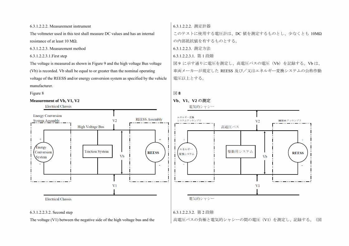
6.3.1.2.2.2. Measurement instrument
The voltmeter used in this test shall measure DC values and has an internal
resistance of at least 10 MΩ.
6.3.1.2.2.2. 測定計器
このテストに使用する電圧計は、DC 値を測定するものとし、少なくとも 10MΩ
の内部抵抗値を有するものとする。
6.3.1.2.2.3. Measurement method 6.3.1.2.2.3. 測定方法
6.3.1.2.2.3.1.First step
The voltage is measured as shown in Figure 9 and the high voltage Bus voltage
(Vb) is recorded. Vb shall be equal to or greater than the nominal operating
voltage of the REESS and/or energy conversion system as specified by the vehicle
manufacturer.
6.3.1.2.2.3.1. 第 1 段階
図 9 に示す通りに電圧を測定し、高電圧バスの電圧(Vb)を記録する。Vb は、
車両メーカーが規定した REESS 及び/又はエネルギー変換システムの公称作動
電圧以上とする。
Figure 8
Measurement of Vb, V1, V2
図 8
Vb、V1、V2 の測定
6.3.1.2.2.3.2. Second step
The voltage (V1) between the negative side of the high voltage bus and the
6.3.1.2.2.3.2. 第 2 段階
高電圧バスの負極と電気的シャシーの間の電圧(V1)を測定し、記録する。(図
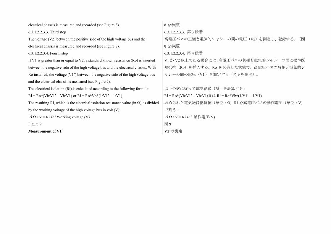
electrical chassis is measured and recorded (see Figure 8). 8 を参照)
6.3.1.2.2.3.3. Third step
The voltage (V2) between the positive side of the high voltage bus and the
electrical chassis is measured and recorded (see Figure 8).
6.3.1.2.2.3.3. 第 3 段階
高電圧バスの正極と電気的シャシーの間の電圧(V2)を測定し、記録する。(図
8 を参照)
6.3.1.2.2.3.4. Fourth step
If V1 is greater than or equal to V2, a standard known resistance (Ro) is inserted
between the negative side of the high voltage bus and the electrical chassis. With
Ro installed, the voltage (V1’) between the negative side of the high voltage bus
and the electrical chassis is measured (see Figure 9).
The electrical isolation (Ri) is calculated according to the following formula:
Ri = Ro*(Vb/V1’ – Vb/V1) or Ri = Ro*Vb*(1/V1’ – 1/V1)
The resulting Ri, which is the electrical isolation resistance value (in Ω), is divided
by the working voltage of the high voltage bus in volt (V):
Ri Ω / V = Ri Ω / Working voltage (V)
6.3.1.2.2.3.4. 第 4 段階
V1 が V2 以上である場合には、高電圧バスの負極と電気的シャシーの間に標準既
知抵抗(Ro)を挿入する。Ro を装備した状態で、高電圧バスの負極と電気的シ
ャシーの間の電圧(V1')を測定する(図 9 を参照)。
以下の式に従って電気絶縁(Ri)を計算する:
Ri = Ro*(Vb/V1’ – Vb/V1)又は Ri = Ro*Vb*(1/V1’ – 1/V1)
求められた電気絶縁抵抗値(単位:Ω)Ri を高電圧バスの動作電圧(単位:V)
で割る:
Ri Ω / V = Ri Ω / 動作電圧(V)
Figure 9
Measurement of V1´
図 9
V1´の測定
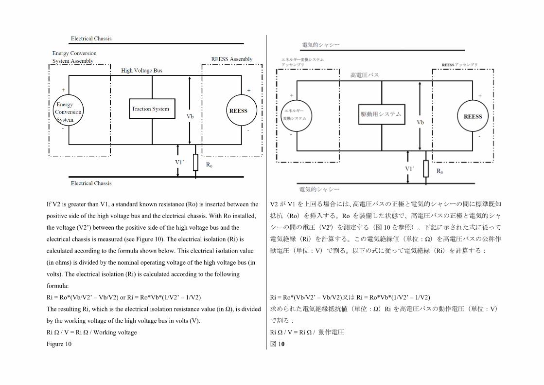
If V2 is greater than V1, a standard known resistance (Ro) is inserted between the
positive side of the high voltage bus and the electrical chassis. With Ro installed,
the voltage (V2’) between the positive side of the high voltage bus and the
electrical chassis is measured (see Figure 10). The electrical isolation (Ri) is
calculated according to the formula shown below. This electrical isolation value
(in ohms) is divided by the nominal operating voltage of the high voltage bus (in
volts). The electrical isolation (Ri) is calculated according to the following
formula:
Ri = Ro*(Vb/V2’ – Vb/V2) or Ri = Ro*Vb*(1/V2’ – 1/V2)
The resulting Ri, which is the electrical isolation resistance value (in Ω), is divided
by the working voltage of the high voltage bus in volts (V).
Ri Ω / V = Ri Ω / Working voltage
V2 が V1 を上回る場合には、高電圧バスの正極と電気的シャシーの間に標準既知
抵抗(Ro)を挿入する。Ro を装備した状態で、高電圧バスの正極と電気的シャ
シーの間の電圧(V2')を測定する(図 10 を参照)。下記に示された式に従って
電気絶縁(Ri)を計算する。この電気絶縁値(単位:Ω)を高電圧バスの公称作
動電圧(単位:V)で割る。以下の式に従って電気絶縁(Ri)を計算する:
Ri = Ro*(Vb/V2’ – Vb/V2)又は Ri = Ro*Vb*(1/V2’ – 1/V2)
求められた電気絶縁抵抗値(単位:Ω)Ri を高電圧バスの動作電圧(単位:V)
で割る:
Ri Ω / V = Ri Ω / 動作電圧
Figure 10 図 10
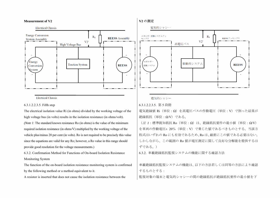
Measurement of V2 V2 の測定
6.3.1.2.2.3.5. Fifth step
The electrical isolation value Ri (in ohms) divided by the working voltage of the
high voltage bus (in volts) results in the isolation resistance (in ohms/volt).
(Note 1: The standard known resistance Ro (in ohms) is the value of the minimum
required isolation resistance (in ohms/V) multiplied by the working voltage of the
vehicle plus/minus 20 per cent (in volts). Ro is not required to be precisely this value
since the equations are valid for any Ro; however, a Ro value in this range should
provide good resolution for the voltage measurements.)
6.3.1.2.2.3.5. 第 5 段階
電気絶縁値 Ri(単位:Ω)を高電圧バスの作動電圧(単位:V)で割った結果が
絶縁抵抗(単位:Ω/V)である。
(注 1:標準既知抵抗 Ro(単位:Ω)は、絶縁抵抗要件の 小値(単位:Ω/V)
を車両の作動電圧± 20%(単位:V)で乗じた値であるべきものとする。当該方
程式はいずれの Ro にも有効であるため、Ro は、厳密にこの値である必要はない。
しかしながら、この範囲の Ro 値が電圧測定に関して良好な分解能を提供するは
ずである。)
6.3.2. Confirmation Method for Functions of On-board Isolation Resistance
Monitoring System
The function of the on-board isolation resistance monitoring system is confirmed
by the following method or a method equivalent to it.
A resistor is inserted that does not cause the isolation resistance between the
6.3.2. 車載絶縁抵抗監視システムの機能に関する確認方法
車載絶縁抵抗監視システムの機能は、以下の方法若しくは同等の方法により確認
するものとする:
監視対象の端末と電気的シャシーの間の絶縁抵抗が絶縁抵抗要件の 小値を下
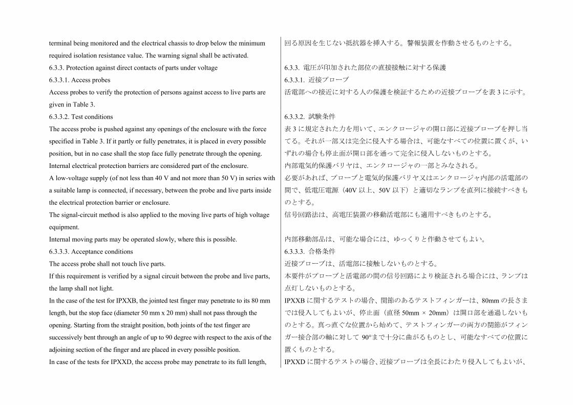
terminal being monitored and the electrical chassis to drop below the minimum
required isolation resistance value. The warning signal shall be activated.
回る原因を生じない抵抗器を挿入する。警報装置を作動させるものとする。
6.3.3. Protection against direct contacts of parts under voltage 6.3.3. 電圧が印加された部位の直接接触に対する保護
6.3.3.1. Access probes
Access probes to verify the protection of persons against access to live parts are
given in Table 3.
6.3.3.1. 近接プローブ
活電部への接近に対する人の保護を検証するための近接プローブを表 3 に示す。
6.3.3.2. Test conditions
The access probe is pushed against any openings of the enclosure with the force
specified in Table 3. If it partly or fully penetrates, it is placed in every possible
position, but in no case shall the stop face fully penetrate through the opening.
Internal electrical protection barriers are considered part of the enclosure.
A low-voltage supply (of not less than 40 V and not more than 50 V) in series with
a suitable lamp is connected, if necessary, between the probe and live parts inside
the electrical protection barrier or enclosure.
The signal-circuit method is also applied to the moving live parts of high voltage
equipment.
Internal moving parts may be operated slowly, where this is possible.
6.3.3.2. 試験条件
表 3 に規定された力を用いて、エンクロージャの開口部に近接プローブを押し当
てる。それが一部又は完全に侵入する場合は、可能なすべての位置に置くが、い
ずれの場合も停止面が開口部を通って完全に侵入しないものとする。
内部電気的保護バリヤは、エンクロージャの一部とみなされる。
必要があれば、プローブと電気的保護バリヤ又はエンクロージャ内部の活電部の
間で、低電圧電源(40V 以上、50V 以下)と適切なランプを直列に接続すべきも
のとする。
信号回路法は、高電圧装置の移動活電部にも適用すべきものとする。
内部移動部品は、可能な場合には、ゆっくりと作動させてもよい。
6.3.3.3. Acceptance conditions
The access probe shall not touch live parts.
If this requirement is verified by a signal circuit between the probe and live parts,
the lamp shall not light.
In the case of the test for IPXXB, the jointed test finger may penetrate to its 80 mm
length, but the stop face (diameter 50 mm x 20 mm) shall not pass through the
opening. Starting from the straight position, both joints of the test finger are
successively bent through an angle of up to 90 degree with respect to the axis of the
adjoining section of the finger and are placed in every possible position.
In case of the tests for IPXXD, the access probe may penetrate to its full length,
6.3.3.3. 合格条件
近接プローブは、活電部に接触しないものとする。
本要件がプローブと活電部の間の信号回路により検証される場合には、ランプは
点灯しないものとする。
IPXXB に関するテストの場合、関節のあるテストフィンガーは、80mm の長さま
では侵入してもよいが、停止面(直径 50mm × 20mm)は開口部を通過しないも
のとする。真っ直ぐな位置から始めて、テストフィンガーの両方の関節がフィン
ガー接合部の軸に対して 90°まで十分に曲がるものとし、可能なすべての位置に
置くものとする。
IPXXD に関するテストの場合、近接プローブは全長にわたり侵入してもよいが、
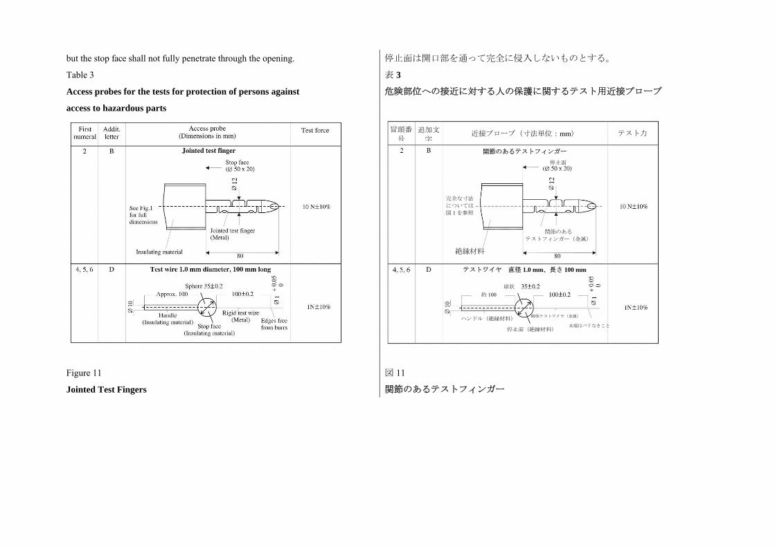
but the stop face shall not fully penetrate through the opening. 停止面は開口部を通って完全に侵入しないものとする。
Table 3
Access probes for the tests for protection of persons against
access to hazardous parts
表 3
危険部位への接近に対する人の保護に関するテスト用近接プローブ
Figure 11
Jointed Test Fingers
図 11
関節のあるテストフィンガー
冒頭番
号
追加文
字近接プローブ(寸法単位:mm) テスト力
関節のあるテストフィンガー
停止面
完全な寸法 については 図 1 を参照
関節のある テストフィンガー(金属)
絶縁材料
テストワイヤ 直径 1.0 mm、長さ 100 mm
球状 約 100
ハンドル(絶縁材料)
停止面(絶縁材料)
剛体テストワイヤ(金属)
末端はバリなきこと
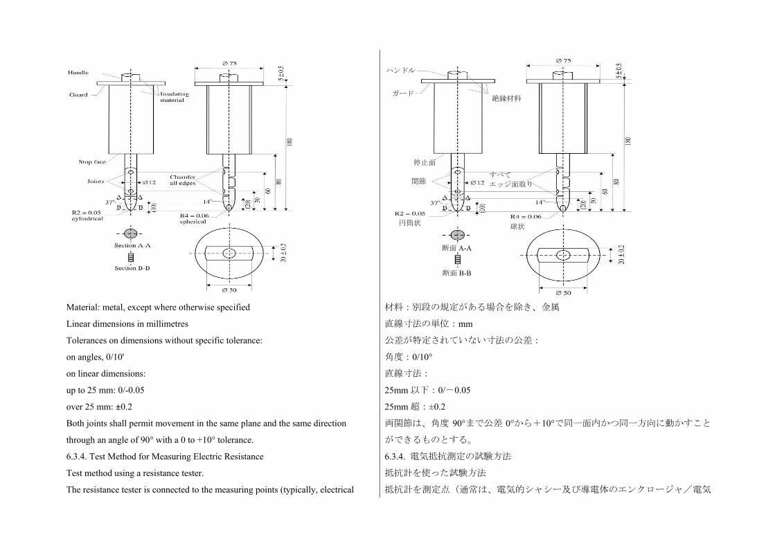
Material: metal, except where otherwise specified
Linear dimensions in millimetres
Tolerances on dimensions without specific tolerance:
on angles, 0/10'
on linear dimensions:
up to 25 mm: 0/-0.05
over 25 mm: ±0.2
Both joints shall permit movement in the same plane and the same direction
through an angle of 90° with a 0 to +10° tolerance.
材料:別段の規定がある場合を除き、金属
直線寸法の単位:mm
公差が特定されていない寸法の公差:
角度:0/10°
直線寸法:
25mm 以下:0/-0.05
25mm 超:±0.2
両関節は、角度 90°まで公差 0°から+10°で同一面内かつ同一方向に動かすこと
ができるものとする。
6.3.4. Test Method for Measuring Electric Resistance
Test method using a resistance tester.
The resistance tester is connected to the measuring points (typically, electrical
6.3.4. 電気抵抗測定の試験方法
抵抗計を使った試験方法
抵抗計を測定点(通常は、電気的シャシー及び導電体のエンクロージャ/電気
ハンドル
ガード絶縁材料
円筒状
停止面
すべて エッジ面取り 関節
球状
断面 A-A
断面 B-B
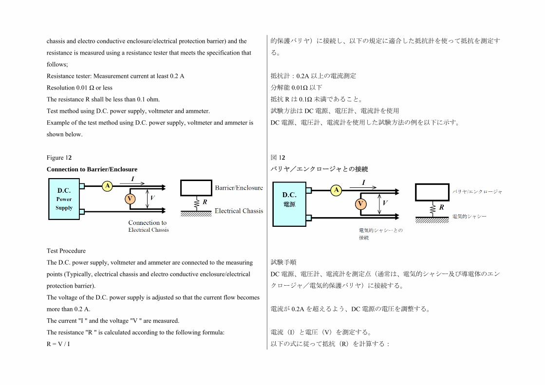
chassis and electro conductive enclosure/electrical protection barrier) and the
resistance is measured using a resistance tester that meets the specification that
follows;
Resistance tester: Measurement current at least 0.2 A
Resolution 0.01 Ω or less
The resistance R shall be less than 0.1 ohm.
Test method using D.C. power supply, voltmeter and ammeter.
Example of the test method using D.C. power supply, voltmeter and ammeter is
shown below.
的保護バリヤ)に接続し、以下の規定に適合した抵抗計を使って抵抗を測定す
る。
抵抗計:0.2A 以上の電流測定
分解能 0.01Ω以下
抵抗 R は 0.1Ω未満であること。
試験方法は DC 電源、電圧計、電流計を使用
DC 電源、電圧計、電流計を使用した試験方法の例を以下に示す。
Figure 12
Connection to Barrier/Enclosure
Test Procedure
The D.C. power supply, voltmeter and ammeter are connected to the measuring
points (Typically, electrical chassis and electro conductive enclosure/electrical
protection barrier).
The voltage of the D.C. power supply is adjusted so that the current flow becomes
more than 0.2 A.
The current "I " and the voltage "V " are measured.
The resistance "R " is calculated according to the following formula:
R = V / I
図 12
バリヤ/エンクロージャとの接続
試験手順
DC 電源、電圧計、電流計を測定点(通常は、電気的シャシー及び導電体のエン
クロージャ/電気的保護バリヤ)に接続する。
電流が 0.2A を超えるよう、DC 電源の電圧を調整する。
電流(I)と電圧(V)を測定する。
以下の式に従って抵抗(R)を計算する:
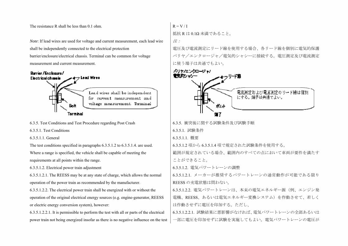
The resistance R shall be less than 0.1 ohm. R = V / I
抵抗 R は 0.1Ω未満であること。
Note: If lead wires are used for voltage and current measurement, each lead wire
shall be independently connected to the electrical protection
barrier/enclosure/electrical chassis. Terminal can be common for voltage
measurement and current measurement.
注:
電圧及び電流測定にリード線を使用する場合、各リード線を個別に電気的保護
バリヤ/エンクロージャ/電気的シャシーに接続する。電圧測定及び電流測定
に使う端子は共通でもよい。
6.3.5. Test Conditions and Test Procedure regarding Post Crash 6.3.5. 衝突後に関する試験条件及び試験手順
6.3.5.1. Test Conditions 6.3.5.1. 試験条件
6.3.5.1.1. General
The test conditions specified in paragraphs 6.3.5.1.2 to 6.3.5.1.4. are used.
Where a range is specified, the vehicle shall be capable of meeting the
requirements at all points within the range.
6.3.5.1.1. 概要
6.3.5.1.2 項から 6.3.5.1.4 項で規定された試験条件を使用する。
範囲が規定されている場合、範囲内のすべての点において車両が要件を満たす
ことができること。
6.3.5.1.2. Electrical power train adjustment 6.3.5.1.2. 電気パワートレーンの調整
6.3.5.1.2.1. The REESS may be at any state of charge, which allows the normal
operation of the power train as recommended by the manufacturer.
6.3.5.1.2.1. メーカーが推奨するパワートレーンの通常動作が可能である限り
REESS の充電状態は問わない。
6.3.5.1.2.2. The electrical power train shall be energized with or without the
operation of the original electrical energy sources (e.g. engine-generator, REESS
or electric energy conversion system), however:
6.3.5.1.2.2. 電気パワートレーンは、本来の電気エネルギー源(例、エンジン発
電機、REESS、あるいは電気エネルギー変換システム)を作動させて、若しく
は作動させずに電圧を印加する。ただし、
6.3.5.1.2.2.1. It is permissible to perform the test with all or parts of the electrical
power train not being energized insofar as there is no negative influence on the test
6.3.5.1.2.2.1. 試験結果に悪影響がなければ、電気パワートレーンの全部あるいは
一部に電圧を印加せずに試験を実施してもよい。電気パワートレーンの電圧が
result. For parts of the electrical power train not energized, the protection against
electric shock shall be proved by either physical protection or isolation resistance
and appropriate additional evidence.
印加されない部分に対する感電防止を、物理的保護若しくは絶縁抵抗及び適切
な付加的証拠により証明すること。
6.3.5.1.2.2.2. If the power train is not energized and an automatic disconnect is
provided, it is permissible to perform the test with the automatic disconnect being
triggered. In this case it shall be demonstrated that the automatic disconnect would
have operated during the impact test. This includes the automatic activation signal
as well as the conductive separation considering the conditions as seen during the
impact.
6.3.5.1.2.2.2. パワートレーンに電圧を印加せず、自動切断が設けられている場
合、自動切断を作動させて試験を実施してもよい。この場合、衝撃試験におい
て自動切断が作動したであろうことを実証すること。これには、自動起動信号
及び衝撃時に見られた条件を考慮した導電的分離が含まれる。
6.3.5.1.3. Contracting parties may allow modifications to the fuel system so that an
appropriate amount of fuel can be used to run the engine or the electrical energy
conversion system.
6.3.5.1.3. 締約国は、エンジンあるいは電気エネルギー変換システムの運転に適
切な量の燃料が使用されるように燃料システムの変更を許可してもよい。
6.3.5.1.4. The vehicle conditions other than specified in paras. 6.3.5.1.1. to
6.3.5.1.3. are in the crash test protocols of the contracting parties.
6.3.5.1.4. 車両条件で、6.3.5.1.1 項から 6.3.5.1.3 項までに規定されたもの以外は、
締約国の衝突試験プロトコルに規定されたものとする。
6.3.5.2. Test Procedures for the protection of the occupants of vehicles operating
on electrical power from high voltage and electrolyte spillage
This section describes test procedures to demonstrate compliance with the
electrical safety requirements of para. 5.3.2.
Before the vehicle impact test conducted, the high voltage bus voltage (Vb) (see
Figure 13) is measured and recorded to confirm that it is within the operating
voltage of the vehicle as specified by the vehicle manufacturer.
6.3.5.2. 電動車両における高電圧及び電解液漏出に対する乗員保護に関する試
験手順
本項では、5.3.2 項の電気的安全要件に対する適合性を実証する試験手順を規定
する。
車両衝撃試験を実施する前に、高電圧バスの電圧(Vb)(図 13 を参照)を測定、
記録し、その値が車両メーカーが規定する車両の動作電圧範囲内であることを
確認する。
6.3.5.2.1. Test setup and equipment
If a high voltage disconnect function is used, measurements are taken from both
sides of the device performing the disconnect function.
However, if the high voltage disconnect is integral to the REESS or the energy
conversion system and the high-voltage bus of the REESS or the energy
conversion system is protected according to protection degree IPXXB following
6.3.5.2.1. 試験の設定及び器具
高電圧切断機能を使用する場合、切断機能を持つ装置の両側で測定を行う。
ただし、高電圧切断が REESS あるいはエネルギー変換システムと一体であり、
かつ衝撃試験の後 REESS の高電圧バス又はエネルギー変換システムが保護等級
IPXXB により保護されている場合、切断機能を実行する装置と電気負荷間での
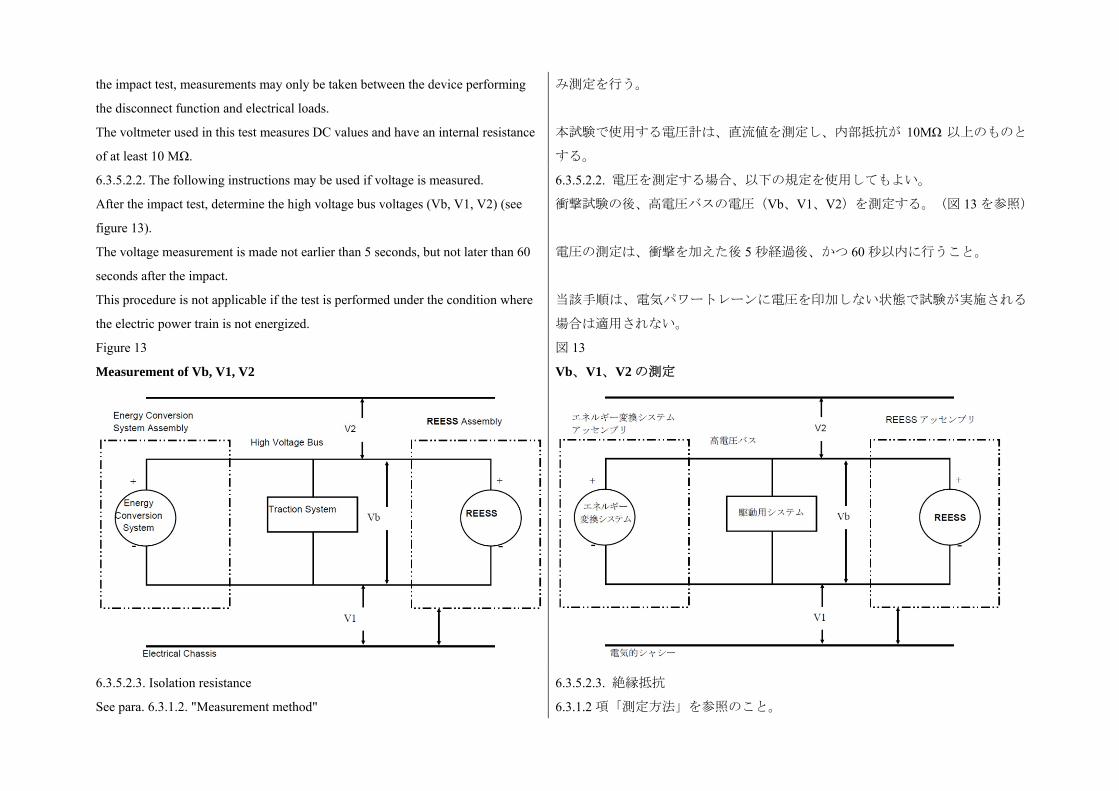
the impact test, measurements may only be taken between the device performing
the disconnect function and electrical loads.
The voltmeter used in this test measures DC values and have an internal resistance
of at least 10 MΩ.
み測定を行う。
本試験で使用する電圧計は、直流値を測定し、内部抵抗が 10MΩ 以上のものと
する。
6.3.5.2.2. The following instructions may be used if voltage is measured.
After the impact test, determine the high voltage bus voltages (Vb, V1, V2) (see
figure 13).
The voltage measurement is made not earlier than 5 seconds, but not later than 60
seconds after the impact.
This procedure is not applicable if the test is performed under the condition where
the electric power train is not energized.
6.3.5.2.2. 電圧を測定する場合、以下の規定を使用してもよい。
衝撃試験の後、高電圧バスの電圧(Vb、V1、V2)を測定する。(図 13 を参照)
電圧の測定は、衝撃を加えた後 5 秒経過後、かつ 60 秒以内に行うこと。
当該手順は、電気パワートレーンに電圧を印加しない状態で試験が実施される
場合は適用されない。
Figure 13
Measurement of Vb, V1, V2
図 13
Vb、V1、V2 の測定
6.3.5.2.3. Isolation resistance
See para. 6.3.1.2. "Measurement method"
6.3.5.2.3. 絶縁抵抗
6.3.1.2 項「測定方法」を参照のこと。

All measurements for calculating voltage(s) and electrical isolation are made after
a minimum of 5 seconds after the impact.
For example, megohmmeter or oscilloscope measurements are an appropriate
alternative to the procedure described above for measuring isolation resistance. In
this case it may be necessary to deactivate the on-board isolation resistance
monitoring system.
電圧及び電気絶縁の計算のためのすべての測定は、衝撃を加えた後 5 秒以上経
過してから行うこと。
例えば、上記の絶縁抵抗測定手順の代替手段として絶縁抵抗計及びオシロスコ
ープによる測定が適している。この場合、車載絶縁抵抗監視システムの解除を
要する場合がある。
6.3.5.2.4. Physical Protection
Following the vehicle crash test, any parts surrounding the high voltage
components are opened, disassembled or removed without the use of tools. All
remaining surrounding parts shall be considered part of the physical protection.
The jointed test finger described in para. 6.3.3. is inserted into any gaps or
openings of the physical protection with a test force of 10 N ± 10 per cent for
electrical safety assessment. If partial or full penetration into the physical
protection by the Jointed Test Finger occurs, the Jointed Test Finger shall be
placed in every position as specified below.
Starting from the straight position, both joints of the test finger are rotated
progressively through an angle of up to 90 degrees with respect to the axis of the
adjoining section of the finger and are placed in every possible position.
Internal electrical protection barriers are considered part of the enclosure
If appropriate, a low-voltage supply (of not less than 40 V and not more than 50 V)
in series with a suitable lamp is connected between the Jointed Test Finger and
high voltage live parts inside the electrical protection barrier or enclosure
6.3.5.2.4. 物理的保護
車両衝突試験の後、高電圧の構成部品の周囲にあるすべての部品を、工具を使
用せずに開放、分解、除去する。これら以外のすべての周辺部品は、物理的保
護の一部と見なす。
6.3.3 項で規定した関節のあるテストフィンガーを物理的保護のあらゆる隙間あ
るいは開口部に 10N±10%の力で侵入させ、電気的安全を評価する。これが一部
又は完全に物理的保護内に進入する場合は、下記に規定するすべての位置にこ
れを置く。
真っ直ぐな位置から始めて、テストフィンガーの両方の関節がフィンガー接合
部の軸に対して 90°まで十分に曲がるものとし、可能なすべての位置に置くもの
とする。
内部電気的保護バリヤは、エンクロージャの一部とみなされる。
必要があれば、関節のあるテストフィンガーと電気的保護バリヤ又はエンクロ
ージャ内部の高電圧活電部の間で、低電圧電源(40V 以上、50V 以下)と適切な
ランプを直列に接続すべきものとする。
6.3.5.2.5. Acceptance conditions
The requirements of para. 5.3.2.2.3. are met if the jointed test finger described in
para. 6.3.3. is unable to contact high voltage live parts.
If necessary a mirror or a fibrescope may be used in order to inspect whether the
jointed test finger touches the high voltage buses.
6.3.5.2.5. 合格条件
6.3.3 項で規定された関節のあるテストフィンガーが高電圧活電部に接触できな
い場合、5.3.2.2.3 項の要求事項に適合していると見なされる。
必要に応じて鏡又はファイバースコープを使用し、関節のあるテストフィンガ
ーが高電圧バスに接触しないことを確認してもよい。
If this requirement is verified by a signal circuit between the jointed test finger and
high voltage live parts, the lamp shall not light.
本要件が関節のあるテストフィンガーと高電圧活電部の間の信号回路により検
証される場合には、ランプは点灯しないものとする。
6.3.5.2.6. Electrolyte spillage
Appropriate coating shall be applied, if necessary, to the physical protection in
order to confirm any electrolyte leakage from the REESS after the impact test.
Unless the manufacturer provides the means to differentiate among the leakage
of different liquids, all liquid leakage is considered as an electrolyte.
6.3.5.2.6. 電解液の漏出
衝撃試験の後、REESS からの電解液の漏出がないか確認するため、必要に応じ
て物理的保護に適切なコーティングを施すこと。
漏出した液体を区別する手段がメーカーから提供されていない場合、すべての
漏出液を電解液と見なす。
6.3.5.2.7. REESS retention
Compliance shall be determined by visual inspection
6.3.5.2.7. REESS の保持
目視検査により適合性を判断する。
7. Vehicles with a liquefied hydrogen storage system (LHSSs) 7. 液体水素貯蔵システム(LHSS)を搭載した車両
7.1. LHSS optional requirements
As described in paras. 23. and 118. of the preamble, individual Contracting Parties
may elect to adopt the gtr with or without the LHSS requirements in para. 7.
Para. 7. is organized as follows:
Para. 7.2. LHSS design qualification requirements
Para. 7.3. LHSS fuel system integrity
Para. 7.4. Test procedures for LHSS design qualification
Para. 7.5. Test procedures for LHSS fuel system integrity
7.1. LHSS に関する任意の要求事項
前文の 23 項及び 118 項で規定された通り、各締約国は 7 項で規定する LHSS に
関する要件を含めた、若しくは含めない gtr を採用することができる。
7 項の構成は以下の通り。
7.2 項 LHSS の設計認定要件
7.3 項 LHSS 燃料システムの完全性
7.4 項 LHSS の設計認定試験手順
7.5 項 LHSS 燃料システムの完全性に関する試験手順
7.2. LHSS design qualification requirements
This Section specifies the requirements for the integrity of a liquefied hydrogen
storage system.
The hydrogen storage system qualifies for the performance test requirements
specified in this Section. All liquefied hydrogen storage systems produced for
on-road vehicle service shall be capable of satisfying requirements of para. 7.2.
The manufacturer shall specify a maximum allowable working pressure (MAWP)
for the inner container.
7.2. LHSS の設計認定要件
本項は、液体水素貯蔵システムの完全性に関する要求事項を規定している。
水素貯蔵システムは、本項で規定した性能試験要件の対象である。路上車両用に
製造されたすべての液体水素貯蔵システムは 7.2 項の要求事項に適合すること。
メーカーは、内装容器の 大許容動作圧(MAWP)を規定すること。
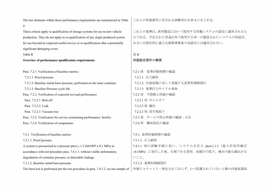
The test elements within these performance requirements are summarized in Table
4.
These criteria apply to qualification of storage systems for use in new vehicle
production. They do not apply to re-qualification of any single produced system
for use beyond its expected useful service or re-qualification after a potentially
significant damaging event.
これらの性能要件に含まれる試験項目を表 4 にまとめる。
これらの基準は、新車製造において使用する貯蔵システムの認定に適用されるも
のである。予定された用途以外で使用する単一の製造されたシステムの再認定、
あるいは潜在的に重大な損傷事象後の再認定には適用されない。
Table 4
Overview of performance qualification requirements
Para. 7.2.1. Verification of baseline metrics
7.2.1.1. Proof pressure
7.2.1.2. Baseline initial burst pressure, performed on the inner container
7.2.1.3. Baseline Pressure cycle life
Para. 7.2.2. Verification of expected on-road performance
Para. 7.2.2.1. Boil-off
Para. 7.2.2.2. Leak
Para. 7.2.2.3. Vacuum loss
Para. 7.2.3. Verification for service terminating performance: bonfire
Para. 7.2.4. Verification of components
表 4
性能認定要件の概要
7.2.1 項 基準評価指標の確認
7.2.1.1. 圧力耐性
7.2.1.2. 内装容器に対して実施する基準初期破裂圧
7.2.1.3. 基準圧力サイクル寿命
7.2.2 項 予想路上性能の確認
7.2.2.1 項 ボイルオフ
7.2.2.2 項 漏出
7.2.2.3 項 真空度低下
7.2.3 項 サービス停止性能の確認:火災
7.2.4 項 構成部品の確認
7.2.1. Verification of baseline metrics 7.2.1. 基準評価指標の確認
7.2.1.1. Proof pressure
A system is pressurized to a pressure ptest ≥ 1.3 (MAWP ± 0.1 MPa) in
accordance with test procedure para. 7.4.1.1. without visible deformation,
degradation of container pressure, or detectable leakage.
7.2.1.1. 圧力耐性
7.4.1.1 項の試験手順に従い、システムを圧力 ptest≧1.3( 大許容作動圧
±0.1MPa)に加圧した後、目視できる変形、容器圧の低下、検出可能な漏出がな
いこと。
7.2.1.2. Baseline initial burst pressure
The burst test is performed per the test procedure in para. 7.4.1.2. on one sample of
7.2.1.2. 基準初期破裂圧
外側ジャケットと一体化されておらず、かつ防護されていない 1 個の内装容器試
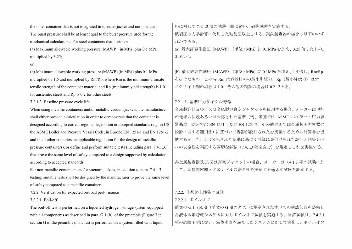
the inner container that is not integrated in its outer jacket and not insulated.
The burst pressure shall be at least equal to the burst pressure used for the
mechanical calculations. For steel containers that is either:
料に対して 7.4.1.2 項の試験手順に従い、破裂試験を実施する。
破裂圧は力学計算に使用した破裂圧以上とする。鋼鉄製容器の場合は以下のいず
れかである。
(a) Maximum allowable working pressure (MAWP) (in MPa) plus 0.1 MPa
multiplied by 3.25;
or
(a) 大許容作動圧(MAWP)(単位:MPa)に 0.1MPa を加え、3.25 倍したもの。
あるいは
(b) Maximum allowable working pressure (MAWP) (in MPa) plus 0.1 MPa
multiplied by 1.5 and multiplied by Rm/Rp, where Rm is the minimum ultimate
tensile strength of the container material and Rp (minimum yield strength) is 1.0
for austenitic steels and Rp is 0.2 for other steels.
(b) 大許容作動圧(MAWP)(単位:MPa)に 0.1MPa を加え、1.5 倍し、Rm/Rp
を掛けたもの。この時 Rm は容器材料の 小引張力、Rp( 小降伏力)はオー
ステナイト鋼の場合は 1.0、その他の鋼鉄の場合は 0.2 である。
7.2.1.3. Baseline pressure cycle life
When using metallic containers and/or metallic vacuum jackets, the manufacturer
shall either provide a calculation in order to demonstrate that the container is
designed according to current regional legislation or accepted standards (e.g. in US
the ASME Boiler and Pressure Vessel Code, in Europe EN 1251-1 and EN 1251-2
and in all other countries an applicable regulation for the design of metallic
pressure containers), or define and perform suitable tests (including para. 7.4.1.3.)
that prove the same level of safety compared to a design supported by calculation
according to accepted standards.
For non-metallic containers and/or vacuum jackets, in addition to para. 7.4.1.3.
testing, suitable tests shall be designed by the manufacturer to prove the same level
of safety compared to a metallic container.
7.2.1.3. 基準圧力サイクル寿命
金属製容器及び/又は金属製の真空ジャケットを使用する場合、メーカーは現行
の地域の法規あるいは公認された基準(例、米国では ASME ボイラー・圧力容
器基準、欧州では EN 1251-1 及び EN 1251-2、その他の国では金属製圧力容器の
設計に関する適用法)に基づいて容器が設計されたを実証するための計算書を提
供するか、若しくは公認された基準に基づく計算に裏付けられた設計と同等レベ
ルの安全性を実証する適切な試験(7.4.1.3 項を含む)を規定しこれを実施する。
非金属製容器及び/又は真空ジャケットの場合、メーカーは 7.4.1.3 項の試験に加
えて、金属製容器と同等レベルの安全性を実証する適切な試験を設定する。
7.2.2. Verification for expected on-road performance 7.2.2. 予想路上性能の確認
7.2.2.1. Boil-off
The boil-off test is performed on a liquefied hydrogen storage system equipped
with all components as described in para. G.1.(b). of the preamble (Figure 7 in
section G of the preamble). The test is performed on a system filled with liquid
7.2.2.1. ボイルオフ
前文の G.1. (b).項(前文の G 項の図 7)に規定されたすべての構成部品を装備し
た液体水素貯蔵システムに対しボイルオフ試験を実施する。当該試験は、7.4.2.1
項の試験手順に従い、液体水素を満たしたシステムに対して実施し、ボイルオフ
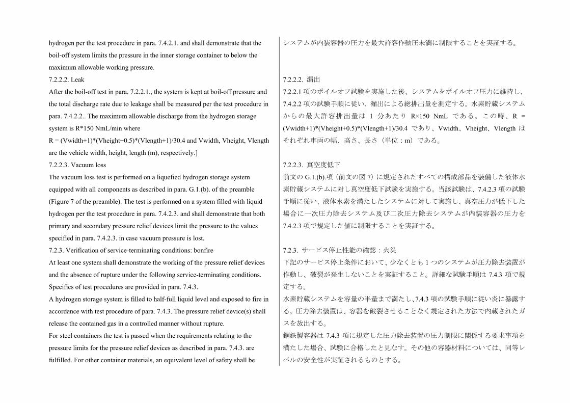
hydrogen per the test procedure in para. 7.4.2.1. and shall demonstrate that the
boil-off system limits the pressure in the inner storage container to below the
maximum allowable working pressure.
システムが内装容器の圧力を 大許容作動圧未満に制限することを実証する。
7.2.2.2. Leak
After the boil-off test in para. 7.2.2.1., the system is kept at boil-off pressure and
the total discharge rate due to leakage shall be measured per the test procedure in
para. 7.4.2.2.. The maximum allowable discharge from the hydrogen storage
system is R*150 NmL/min where
R = (Vwidth+1)*(Vheight+0.5)*(Vlength+1)/30.4 and Vwidth, Vheight, Vlength
are the vehicle width, height, length (m), respectively.]
7.2.2.2. 漏出
7.2.2.1 項のボイルオフ試験を実施した後、システムをボイルオフ圧力に維持し、
7.4.2.2 項の試験手順に従い、漏出による総排出量を測定する。水素貯蔵システム
からの 大許容排出量は 1 分あたり R×150 NmL である。この時、R =
(Vwidth+1)*(Vheight+0.5)*(Vlength+1)/30.4 であり、Vwidth、Vheight、Vlength は
それぞれ車両の幅、高さ、長さ(単位:m)である。
7.2.2.3. Vacuum loss
The vacuum loss test is performed on a liquefied hydrogen storage system
equipped with all components as described in para. G.1.(b). of the preamble
(Figure 7 of the preamble). The test is performed on a system filled with liquid
hydrogen per the test procedure in para. 7.4.2.3. and shall demonstrate that both
primary and secondary pressure relief devices limit the pressure to the values
specified in para. 7.4.2.3. in case vacuum pressure is lost.
7.2.2.3. 真空度低下
前文の G.1.(b).項(前文の図 7)に規定されたすべての構成部品を装備した液体水
素貯蔵システムに対し真空度低下試験を実施する。当該試験は、7.4.2.3 項の試験
手順に従い、液体水素を満たしたシステムに対して実施し、真空圧力が低下した
場合に一次圧力除去システム及び二次圧力除去システムが内装容器の圧力を
7.4.2.3 項で規定した値に制限することを実証する。
7.2.3. Verification of service-terminating conditions: bonfire
At least one system shall demonstrate the working of the pressure relief devices
and the absence of rupture under the following service-terminating conditions.
Specifics of test procedures are provided in para. 7.4.3.
A hydrogen storage system is filled to half-full liquid level and exposed to fire in
accordance with test procedure of para. 7.4.3. The pressure relief device(s) shall
release the contained gas in a controlled manner without rupture.
For steel containers the test is passed when the requirements relating to the
pressure limits for the pressure relief devices as described in para. 7.4.3. are
fulfilled. For other container materials, an equivalent level of safety shall be
7.2.3. サービス停止性能の確認:火災
下記のサービス停止条件において、少なくとも 1 つのシステムが圧力除去装置が
作動し、破裂が発生しないことを実証すること。詳細な試験手順は 7.4.3 項で規
定する。
水素貯蔵システムを容量の半量まで満たし、7.4.3 項の試験手順に従い炎に暴露す
る。圧力除去装置は、容器を破裂させることなく規定された方法で内蔵されたガ
スを放出する。
鋼鉄製容器は 7.4.3 項に規定した圧力除去装置の圧力制限に関係する要求事項を
満たした場合、試験に合格したと見なす。その他の容器材料については、同等レ
ベルの安全性が実証されるものとする。
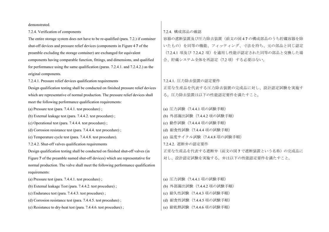
demonstrated.
7.2.4. Verification of components
The entire storage system does not have to be re-qualified (para. 7.2.) if container
shut-off devices and pressure relief devices (components in Figure 4 7 of the
preamble excluding the storage container) are exchanged for equivalent
components having comparable function, fittings, and dimensions, and qualified
for performance using the same qualification (paras. 7.2.4.1. and 7.2.4.2.) as the
original components.
7.2.4. 構成部品の確認
容器の遮断装置及び圧力除去装置(前文の図 4 7 の構成部品のうち貯蔵容器を除
いたもの)を同等の機能、フィッティング、寸法を持ち、元の部品と同じ認定
(7.2.4.1 項及び 7.2.4.2 項)を適用し性能が認定された同等の部品と交換した場
合、貯蔵システム全体を再認定(7.2 項)する必要はない。
7.2.4.1. Pressure relief devices qualification requirements
Design qualification testing shall be conducted on finished pressure relief devices
which are representative of normal production. The pressure relief devices shall
meet the following performance qualification requirements:
7.2.4.1. 圧力除去装置の認定要件
正常な生産品を代表する圧力除去装置の完成品に対し、設計認定試験を実施す
る。圧力除去装置は以下の性能認定要件を満たすこと。
(a) Pressure test (para. 7.4.4.1. test procedure) ;
(b) External leakage test (para. 7.4.4.2. test procedure) ;
(c) Operational test (para. 7.4.4.4. test procedure) ;
(d) Corrosion resistance test (para. 7.4.4.4. test procedure) ;
(e) Temperature cycle test (para. 7.4.4.8. test procedure).
(a) 圧力試験(7.4.4.1 項の試験手順)
(b) 外部漏出試験(7.4.4.2 項の試験手順)
(c) 動作試験(7.4.4.4 項の試験手順)
(d) 耐食性試験(7.4.4.4 項の試験手順)
(e) 温度サイクル試験(7.4.4.8 項の試験手順)
7.2.4.2. Shut-off valves qualification requirements
Design qualification testing shall be conducted on finished shut-off valves (in
Figure 7 of the preamble named shut-off devices) which are representative for
normal production. The valve shall meet the following performance qualification
requirements:
7.2.4.2. 遮断弁の認定要件
正常な生産品を代表する遮断弁(前文の図 7 で遮断装置という名称)の完成品に
対し、設計認定試験を実施する。弁は以下の性能認定要件を満たすこと。
(a) Pressure test (para. 7.4.4.1. test procedure) ;
(b) External leakage Test (para. 7.4.4.2. test procedure) ;
(c) Endurance test (para. 7.4.4.3. test procedure) ;
(d) Corrosion resistance test (para. 7.4.4.5. test procedure) ;
(e) Resistance to dry-heat test (para. 7.4.4.6. test procedure) ;
(a) 圧力試験(7.4.4.1 項の試験手順)
(b) 外部漏出試験(7.4.4.2 項の試験手順)
(c) 耐久性試験(7.4.4.3 項の試験手順)
(d) 耐食性試験(7.4.4.5 項の試験手順)
(e) 耐乾熱試験(7.4.4.6 項の試験手順)
(f) Ozone ageing test (para. 7.4.4.7. test procedure) ;
(g) Temperature cycle test (para. 7.4.4.8. test procedure) ;
(h) Flex line cycle test (para. 7.4.4.9. test procedure).
(f) オゾン劣化試験(7.4.4.7 項の試験手順)
(g) 温度サイクル試験(7.4.4.8 項の試験手順)
(h) フレックスラインサイクル試験(7.4.4.9 項の試験手順)
7.2.5. Labelling
A label shall be permanently affixed on each container with at least the following
information: Name of the Manufacturer, Serial Number, Date of Manufacture,
MAWP, Type of Fuel. Any label affixed to the container in compliance with this
section shall remain in place. Contracting parties may specify additional labelling
requirements.
7.2.5. ラベル表示
各容器には、恒久的なラベルを取り付けること。ラベルには 低でも、製造者
名、シリアル番号、製造日、 大許容作動圧、燃料の種類を記載すること。本
項の規定に従い取り付けるラベルは、外れることなくその位置を維持すること。
締約国はラベル表示に関する追加要件を規定してもよい。
7.3. LHSS fuel system integrity
This section specifies requirements for the integrity of the hydrogen fuel delivery
system, which includes the liquefied hydrogen storage system, piping, joints, and
components in which hydrogen is present. These requirements are in addition to
requirements specified in para. 5.2., all of which apply to vehicles with liquefied
hydrogen storage systems with the exception of para. 5.2.1.1. The fuelling
receptacle label shall designate liquid hydrogen as the fuel type. Test procedures
are given in para. 7.5.
7.3. LHSS 燃料システムの完全性
本セクションでは、水素燃料供給システムの完全性に関する要求事項を規定す
る。これには、液体水素貯蔵システム、配管、継手、水素が介在するコンポー
ネントが含まれる。これらの要件は 5.2 項で規定された、液体水素貯蔵システム
を搭載した車両に適用される要件のうち 5.2.1.1 項を除いたものの追加的要件で
ある。燃料投入口に設置するラベルには、燃料の種類として液体水素と表示す
ること。試験手順は 7.5 項に規定する。
7.3.1. Flammable materials used in the vehicle shall be protected from liquefied air
that may condense on elements of the fuel system.
7.3.1. 車両内に使用されている可燃性の材料は、燃料システムの構成部品に凝結
する可能性のある液化空気から保護すること。
7.3.2. The insulation of the components shall prevent liquefaction of the air in
contact with the outer surfaces, unless a system is provided for collecting and
vaporizing the liquefied air. The materials of the components nearby shall be
compatible with an atmosphere enriched with oxygen.
7.3.2. 液化空気を回収及び気化する機能を備えていないシステムの場合、構成部
品の防護は、外面と接する空気の液化を防ぐものとする。近辺の構成部品の材
質は、酸素含有量の高い空気に対応できるものとする。
7.4. Test procedures for LHSS design qualification 7.4. LHSS の設計認定試験手順
7.4.1. Verification tests for Baseline metrics 7.4.1. 基準評価指標の確認試験
7.4.1.1. Proof pressure test
The inner container and the pipe work situated between the inner container and the
7.4.1.1. 耐圧試験
内装容器及び内装容器と外側ジャケット間の配管は、以下の要求事項に従い、
outer jacket shall withstand an inner pressure test at room temperature according to
the following requirements.
The test pressure ptest is defined by the manufacturer and shall fulfil the following
requirements:
ptest ≥ 1.3 (MAWP ± 0.1 MPa)
室温にて内圧試験に耐えること。
試験圧力 ptestはメーカーが規定し、以下の要件を満たすこと。
ptest≧1.3 ( 大許容作動圧 ±0.1MPa)
(a) For metallic containers, either ptest is equal to or greater than the maximum
pressure of the inner container during fault management (as determined in para.
7.4.2.3.) or the manufacturer proves by calculation that at the maximum pressure
of the inner container during fault management no yield occurs;
(a) 金属製容器の場合、(7.4.2.3 項に規定した)故障管理時の ptestは内装容器の
大圧以上であるか、あるいは故障管理時における 大圧で内装容器に降伏が
発生しないことをメーカーが計算により証明する。
(b) For non-metallic containers, ptest is equal to or greater than the maximum
pressure of the inner container during fault management (as determined in para.
7.4.2.3.).
(b) 非金属製容器の場合、(7.4.2.3 項に規定した)故障管理時の ptestは内装容器
の 大圧以上とする。
The test is conducted according to the following procedure: 当該試験は以下の手順に従い、実施する。
(a) The test is conducted on the inner storage container and the interconnecting
pipes between inner storage container and vacuum jacket before the outer jacket is
mounted;
(b) The test is either conducted hydraulically with water or a glycol/water mixture,
or alternatively with gas. The container is pressurized to test pressure ptest at an
even rate and kept at that pressure for at least 10 minutes;
(c) The test is done at ambient temperature. In the case of using gas to pressurize
the container, the pressurization is done in a way that the container temperature
stays at or around ambient temperature.
The test is passed successfully if, during the first 10 minutes after applying the
proof pressure, no visible permanent deformation, no visible degradation in the
container pressure and no visible leakage are detectable.
(a) 内装貯蔵容器及び内装貯蔵容器と真空ジャケットの間を相互接続する配管
に対し、外側ジャケットを装着する前の状態で試験を実施する。
(b) 試験は水あるいはグリコールと水の混合液による水圧を使用して実施する
か、若しくは代替としてガスを使用して実施する。容器を試験圧力 ptestに均一な
速度で加圧し、10 分以上その圧力を維持する。
(c) 試験は常温で行う。容器の加圧にガスを使用する場合、容器の温度が常温あ
るいはそれに近い温度を維持するように加圧する。
保証耐圧力を印加している 10 分間に、恒久的な変形、容器圧の低下、及び漏出
が見られない場合、試験に合格したと見なす。
7.4.1.2. Baseline initial burst pressure 7.4.1.2. 基準初期破裂圧
The test is conducted according to the following procedure: 当該試験は以下の手順に従い、実施する。

(a) The test is conducted on the inner container at ambient temperature;
(b) The test is conducted hydraulically with water or a water/glycol mixture;
(c) The pressure is increased at a constant rate, not exceeding 0.5 MPa/min until
burst or leakage of the container occurs;
(d) When MAWP is reached there is a wait period of at least ten minutes at
constant pressure, during which time the deformation of the container can be
checked;
(e) The pressure is recorded or written during the entire test.
For steel inner containers, the test is passed successfully if at least one of the two
passing criteria described in para. 5.2.1.2. is fulfilled. For inner containers made
out of an aluminium alloy or other material, a passing criterion shall be defined
which guarantees at least the same level of safety compared to steel inner
containers.
(a) 試験は常温で内装容器に対して実施する。
(b) 試験は水あるいはグリコールと水の混合液による水圧を使用して実施する。
(c) 圧力を 1 分あたり 0.5MPa 未満の均一な速度で、容器の破裂若しくは漏出が
発生するまで増大させる。
(d) 大許容作動圧に到達したらその圧力で 10 分以上待ち、その間容器の変形
を確認する。
(e) 試験中の全期間にわたり、圧力を記録するかあるいは書き留める。
鋼鉄製の内装容器の場合、5.2.1.2 項に規定された合格基準の 1 つ以上を満たし
た場合に合格と見なす。アルミニウム合金あるいはその他の材質の内装容器の
場合、鋼鉄製内装容器と同等以上の安全性を保証する合格基準を規定すること。
7.4.1.3. Baseline pressure cycle life
Containers and/or vacuum jackets are pressure cycled with a number of cycles at
least three times the number of possible full pressure cycles (from the lowest to
highest operating pressure) for an expected on-road performance. The number of
pressure cycles is defined by the manufacturer under consideration of operating
pressure range, size of the storage and, respectively, maximum number of
refuellings and maximum number of pressure cycles under extreme usage and
storage conditions. Pressure cycling is conducted between atmospheric pressure
and MAWP at liquid nitrogen temperatures, e.g. by filling the container with liquid
nitrogen to certain level and alternately pressurizing and depressurizing it with
(pre-cooled) gaseous nitrogen or helium.
7.4.1.3. 基準圧力サイクル寿命
容器及び/又は真空ジャケットに対し、予定路上性能に対して可能な全圧力サ
イクル( 小作動圧から 大作動圧まで)の 3 倍以上の回数の圧力サイクルを
実施する。圧力サイクルの回数は、作動圧の範囲、貯蔵容量、及び極度の使用
時と貯蔵状態における 大燃料供給回数と 大圧力サイクル回数をそれぞれ考
慮してメーカーが規定する。大気圧と異なる液体窒素温度における 大許容作
動圧とで、例えば容器を液体窒素で特定のレベルまで満たし、(予冷した)窒
素ガスあるいはヘリウムガスを使って加圧と減圧を交互に行うなどして、圧力
サイクリングを実施する。
7.4.2. Verification for expected on-road performance 7.4.2. 予定路上性能の確認
7.4.2.1. Boil-off test
The test is conducted according to the following procedure:
7.4.2.1. ボイルオフ試験
当該試験は以下の手順に従い、実施する。
(a) For pre-conditioning, the container is fuelled with liquid hydrogen to the
specified maximum filling level. Hydrogen is subsequently extracted until it meets
half filling level, and the system is allowed to completely cool down for at least 24
hours and a maximum of 48 hours;
(b) The container is filled to the specified maximum filling level;
(c) The container is pressurized until boil-off pressure is reached;
(d) The test lasts for at least another 48 hours after boil-off started and is not
terminated before the pressure stabilizes. Pressure stabilization has occurred when
the average pressure does not increase over a two hour period.
(a) 事前コンディショニングとして、容器に規定 大充填レベルまで液体水素を
満たす。続いて規定の半量の充填レベルまで水素を取り出し、システムを 24 時
間以上 長 48 時間まで放置して完全に落ち着かせる。
(b) 容器を規定 大充填レベルまで満たす。
(c) 容器をボイルオフ圧力に達するまで加圧する。
(d) 試験はボイルオフが開始してからさらに少なくとも 48 時間以上継続し、圧
力が安定するまで終了しない。2 時間の間、平均圧力が上昇しなければ圧力が安
定したと見なす。
The pressure of the inner container is recorded or written during the entire test.
The test is passed successfully if the following requirements are fulfilled:
(a) The pressure stabilizes and stays below MAWP during the whole test;
(b) The pressure relief devices are not allowed to open during the whole test.
試験中の全期間にわたり、内装容器の圧力を記録するかあるいは書き留める。
下記の要求事項が満たされた場合、試験に合格したと見なす。
(a) 試験中の全期間にわたり、圧力が安定し、 大許容作動圧未満を維持した。
(b) 試験中の全期間にわたり、圧力除去装置が開放されることがなかった。
The pressure of the inner container shall be recorded or written during the entire
test. The test is passed when the following requirements are fulfilled:
(a) The pressure shall stabilize and stay below MAWP during the whole test;
(b) The pressure relief devices are not allowed to open during the whole test.
試験中の全期間にわたり、内装容器の圧力を記録するかあるいは書き留める。
下記の要求事項が満たされた場合、試験に合格したと見なす。
(a) 試験中の全期間にわたり、圧力が安定し、 大許容作動圧未満を維持した。
(b) 試験中の全期間にわたり、圧力除去装置が開放されることがなかった。
7.4.2.2. Leak test
The test shall is conducted according to the procedure described in para. 7.4.4.2.
7.4.2.2. 漏出試験
7.4.4.2 項に規定された手順に従い、試験を実施する。
7.4.2.3. Vacuum loss test
The first part of the test is conducted according to the following procedure:
(a) The vacuum loss test is conducted with a completely cooled-down container
(according to the procedure in para. 7.4.2.1.);
(b) The container is filled with liquid hydrogen to the specified maximum filling
level;
(c) The vacuum enclosure is flooded with air at an even rate to atmospheric
pressure;
7.4.2.3. 真空度低下試験
試験の前半は、以下の手順に従って実施する。
(a) 真空度低下試験は、(7.4.2.1 項の手順に従い)完全に安定させ容器を使って
実施する。
(b) 容器に規定 大充填レベルまで液体水素を満たす。
(c) 真空エンクロージャに均一な速度で、大気圧になるまで空気を充満させる。
(d) The test is terminated when the first pressure relief device does not open any
more.
(d) 一次圧力除去装置がそれ以上開放しなければ試験は終了する。
The pressure of the inner container and the vacuum jacket is recorded or written
during the entire test. The opening pressure of the first safety device is recorded or
written. The first part of test is passed if the following requirements are fulfilled:
(a) The first pressure relief device opens below or at MAWP and limit the pressure
to not more than 110 per cent of the MAWP;
(b) The first pressure relief device does not open at pressure above MAWP;
(c) The secondary pressure relief device does not open during the entire test.
試験中の全期間にわたり、内装容器及び真空ジャケットの圧力を記録するかあ
るいは書き留める。主安全装置の開放圧力を記録するかあるいは書き留める。
下記の要求事項が満たされた場合、前半の試験に合格したと見なす。
(a) 一次圧力除去装置が 大許容作動圧以下で開放し、圧力を 大許容作動圧の
110%以下に制限した。
(b) 一次圧力除去装置が 大許容作動圧を超えた圧力で開放しない。
(c) 二次圧力除去装置が、試験中の全期間にわたり開放しない。
After passing the first part, the test shall be repeated subsequently to re-generation
of the vacuum and cool-down of the container as described above.
(a) The vacuum is re-generated to a value specified by the manufacturer. The
vacuum shall be maintained at least 24 hours. The vacuum pump may stay
connected until the time directly before the start of the vacuum loss;
(b) The second part of the vacuum loss test is conducted with a completely
cooled-down container (according to the procedure in para. 7.4.2.1.);
(c) The container is filled to the specified maximum filling level;
(d) The line downstream the first safety relief device is blocked and the vacuum
enclosure is flooded with air at an even rate to atmospheric pressure;
(e) The test is terminated when the second pressure relief device does not open any
more.
The pressure of the inner container and the vacuum jacket is recorded or written
during the entire test. For steel containers the second part of the test is passed if the
second pressure relief device does not open below 110 per cent of the set pressure
of the first safety relief device and limits the pressure in the container to a
maximum 136 per cent of the MAWP if a safety valve is used, or, 150 per cent of
the MAWP if a burst disk is used as the second safety relief device. For other
前半の試験に合格した後、試験は下記に従い、引き続き真空の再生成及び容器
の安定を繰り返す。
(a) メーカーが規定する値に真空を再生成する。少なくとも 24 時間以上真空を
維持する。真空度低下を開始する直前まで真空ポンプを接続したままでよい。
(b) 後半の真空度低下試験は、(7.4.2.1 項の手順に従い)完全に安定させた容器
を使って実施する。
(c) 容器を規定 大充填レベルまで満たす。
(d) 一次安全装置の下流にある配管を閉鎖し、真空エンクロージャに均一な速度
で、大気圧になるまで空気を充満させる。
(e) 二次圧力除去装置がそれ以上開放しなければ試験は終了する。
試験中の全期間にわたり、内装容器及び真空ジャケットの圧力を記録するかあ
るいは書き留める。鋼鉄製容器の場合、二次圧力除去装置が一次圧力除去装置
の設定圧の 110%未満で開放せず、容器内の圧力を、二次安全装置として安全弁
を使用する場合は 大許容作動圧の 大 136%に、バーストディスクを使用する
場合は 大許容作動圧の 150%に制限できれば試験に合格したと見なす。その他
の材質の内装容器の場合、同等の安全性を実証すること。
container materials, an equivalent level of safety shall be demonstrated.
7.4.3. Verification test for service-terminating performance due to fire
The tested liquefied hydrogen storage system shall be representative of the design
and the manufacturing of the type to be homologated. Its manufacturing shall be
completely finished and it shall be mounted with all its equipment.
The first part of the test is conducted according to the following procedure:
(a) The bonfire test is conducted with a completely cooled-down container
(according to the procedure in para. 7.4.2.1.);
(b) The container contained during the previous 24 hours a volume of liquid
hydrogen at least equal to half of the water volume of the inner container;
(c) The container is filled with liquid hydrogen so that the quantity of liquid
hydrogen measured by the mass measurement system is half of the maximum
allowed quantity that may be contained in the inner container;
(d) A fire burns 0.1 m underneath the container. The length and the width of the
fire exceed the plan dimensions of the container by 0.1 m. The temperature of the
fire is at least 590 ºC. The fire shall continue to burn for the duration of the test;
(e) The pressure of the container at the beginning of the test is between 0 MPa and
0.01 MPa at the boiling point of hydrogen in the inner container;
(f) The test shall continue until the storage pressure decreases to or below the
pressure at the beginning of the test, or alternatively in case the first PRD is a
re-closing type, the test shall continue until the safety device has opened for a
second time;
(g) The test conditions and the maximum pressure reached within the container
during the test are recorded in a test certificate signed by the manufacturer and the
technical service.
7.4.3. 火災によるサービス停止性能の確認試験
試験対象の液体水素貯蔵システムは、認定対象のシステムの設計及び製造を代
表するものであること。システムはその製造を完了しており、すべての付帯機
器が取り付けられた状態であること。
試験の前半は、以下の手順に従って実施する。
(a) (7.4.2.1 項の規定に従い)完全に安定させた容器に対し、火災試験を実施す
る。
(b) 試験の 24 時間前から、内装容器の 大許容量の半分以上の水量まで容器に
液体水素を充填しておく。
(c) 質量測定システムで測定した液体水素量が内装容器の 大許容量の半量に
なるよう、容器に液体水素を充填する。
(d) 容器の下 0.1m の位置で炎を燃やす。炎の長さと幅は、容器の設計寸法を 0.1m
超えるものとする。炎の温度は 590以上とする。炎は試験中の全期間にわたっ
て燃え続けるものとする。
(e) 試験開始時の容器圧は、内装容器の水素の沸点で 0MPa から 0.01MPa の間と
する。
(f) 試験は容器圧が試験開始時の圧力以下に低下するまで継続するか、あるいは
一次 PRD が再閉式である場合、安全装置が 2 度目に開放されるまで継続する。
(g) 試験条件及び試験中に容器内で到達した 大圧を、試験証明書に記録し、メ
ーカー及び技術サービスがこれに署名する。
The test is passed if the following requirements are fulfilled:
(a) The secondary pressure relief device is not operated below 110 per cent of the
下記の要求事項が満たされた場合、試験に合格したと見なす。
(a) 二次圧力除去装置が一次圧力除去装置の設定圧の 110%未満で作動しない。
set pressure of the primary pressure relief device;
(b) The container shall not burst and the pressure inside the inner container shall
not exceed the permissible fault range of the inner container.
The permissible fault range for steel containers is as follows:
(a) If a safety valve is used as secondary pressure relief device, the pressure inside
the container does not exceed 136 per cent of the MAWP of the inner container;
(b) If a burst disk is used outside the vacuum area as secondary pressure relief
device, the pressure inside the container is limited to 150 per cent of the MAWP of
the inner container;
(c) If a burst disk is used inside the vacuum area as secondary pressure relief
device, the pressure inside the container is limited to 150 per cent of the Maximum
Allowable Working Pressure plus 0.1 MPa (MAWP ± 0.1 MPa) of the inner
container.
For other materials, an equivalent level of safety shall be demonstrated.
(b) 容器は破裂せず、内装容器内部の圧力が内装容器の許容故障範囲を超えな
い。
鋼鉄製容器の許容故障範囲は以下の通り。
(a) 二次圧力除去装置として安全弁を使用する場合、容器内の圧力は内装容器の
大許容作動圧の 136%を超えない。
(b) 真空域外で二次圧力除去装置としてバーストディスクを使用する場合、容器
内の圧力は内装容器の 大許容作動圧の 150%に制限される。
(c) 真空域内で二次圧力除去装置としてバーストディスクを使用する場合、容器
内の圧力は内装容器の 大許容作動圧に 0.1MPa を加えた値( 大許容作動圧
±0.1MPa)の 150%に制限される。
その他の材質の内装容器の場合、同等の安全性を実証すること。
7.4.4. Component Verification Tests
Testing shall be performed with hydrogen gas having gas quality compliant with
ISO 14687-2/SAE J2719. All tests shall be performed at ambient temperature 20
(±5) °C unless otherwise specified. The TPRD qualification performance tests are
specified as follows:
7.4.4. 構成部品の確認試験
試験は、ISO 14687-2/SAE J2719 に適合した品質の水素ガスを使って実施する。
別途指定がない限り、すべての試験は周囲温度 20(±5)で行う。TPRD の認定性
能試験に関する規定は以下の通り。
7.4.4.1. Pressure test
A hydrogen containing component shall withstand without any visible evidence of
leak or deformation a test pressure of 150 per cent MAWP with the outlets of the
high pressure part plugged. The pressure shall subsequently be increased from 150
per cent to 300 per cent MAWP. The component shall not show any visible
evidence of rupture or cracks.
The pressure supply system shall be equipped with a positive shut-off valve and a
pressure gauge having a pressure range of not less than 150 per cent and no more
7.4.4.1. 耐圧試験
水素を包含する構成部品は、高圧部のアウトレットを閉鎖した状態で、 大許
容作動圧の 150%の試験圧力に耐え、漏出や変形が見られないこと。引き続き圧
力を 大許容作動圧の 150%から 300%まで増大し、破裂や割れなどの痕跡が見
られないこと。
圧力供給システムには、正動作遮断弁及び圧力範囲が試験圧力の 150%以上
200%以下の圧力計が装備されていること。圧力計の精度は圧力範囲の 1%であ
than 200 per cent of the test pressure; the accuracy of the gauge shall be 1 per cent
of the pressure range.
For components requiring a leakage test, this test shall be performed prior to the
pressure test.
ること。
漏出試験の実施が必要な構成部品は、耐圧試験の前に漏出試験を実施すること。
7.4.4.2. External leakage test
A component shall be free from leakage through stem or body seals or other joints,
and shall not show evidence of porosity in casting when tested as described in
para. 7.4.4.3.3. at any gas pressure between zero and its MAWP.
The test shall be performed on the same equipment at the following conditions:
(a) At ambient temperature;
(b) At the minimum operating temperature or at liquid nitrogen temperature after
sufficient conditioning time at this temperature to ensure thermal stability;
(c) At the maximum operating temperature after sufficient conditioning time at this
temperature to ensure thermal stability.
During this test, the equipment under test shall be connected to a source of gas
pressure. A positive shut-off valve and a pressure gauge having a pressure range of
not less than 150 per cent and not more than 200 per cent of the test pressure shall
be installed in the pressure supply piping; the accuracy of the gauge shall be 1 per
cent of the pressure range. The pressure gauge shall be installed between the
positive shut-off valve and the sample under test.
Throughout the test, the sample shall be tested for leakage, with a surface active
agent without formation of bubbles or measured with a leakage rate less than 216
Nml/hour.
7.4.4.2. 外部漏出試験
構成部品は、7.4.4.3.3 項の規定に従い、0 から 大許容作動圧までの任意のガス
圧で試験を実施し、ステムシール、ボディーシール、あるいはその他の接合部
からの漏出及び鋳物に鋳巣の発生がないこと。
試験は、同一の装置を使って、以下の条件で実施する。
(a) 常温
(b) 低動作温度あるいは液体窒素温度。ただしこの温度で充分にコンディショ
ニングを行い、熱的安定性を事前に確保する。
(c) 高動作温度。ただしこの温度で充分にコンディショニングを行い、熱的安
定性を事前に確保する。
本試験中、被験装置をガス圧力源に接続する。圧力供給配管には、正動作遮断
弁及び圧力範囲が試験圧力の 150%以上 200%以下の圧力計が設置されているこ
と。圧力計の精度は圧力範囲の 1%であること。圧力計は、正動作遮断弁と被験
試料間に設置すること。
試験中の全期間にわたり、試料に対して界面活性剤を使った漏出試験を実施し
発泡がないこと、若しくは漏出速度が 216Nml/時未満であることを確認する。
7.4.4.3. Endurance test 7.4.4.3. 耐久性試験
7.4.4.3.1. A component shall be capable of conforming to the applicable leakage
test requirements of paras. 7.4.4.2. and 7.4.4.9., after being subjected to 20000
operation cycles.
7.4.4.3.1. 構成部品は、20,000 回の動作サイクル試験を実施した後、7.4.4.2 項及
び 7.4.4.9 項の漏出試験の適用要求事項に適合していること。
7.4.4.3.2. The appropriate tests for external leakage and seat leakage, as described
in paras. 7.4.4.2. and 7.4.4.9. shall be carried out immediately following the
endurance test.
7.4.4.3.2. 耐久性試験を実施した後、直ちに 7.4.4.2 項及び 7.4.4.9 項で規定した適
切な外部漏出試験及び弁座漏出試験を実施すること。
7.4.4.3.3. The shut-off valve shall be securely connected to a pressurized source of
dry air or nitrogen and subjected to 20,000 operation cycles. A cycle shall consist
of one opening and one closing of the component within a period of not less than
10 ± 2 seconds.
7.4.4.3.3. 遮断弁は圧縮乾燥空気あるいは圧縮窒素の供給源と確実に接続し、
20,000 回の動作サイクルを実施する。1 サイクルは、10±2 秒以上の間に構成部
品が一度開放し、一度閉鎖するものとする。
7.4.4.3.4. The component shall be operated through 96 per cent of the number of
specified cycles at ambient temperature and at the MAWP of the component.
During the off cycle the downstream pressure of the test fixture shall be allowed to
decay to 50 per cent of the MAWP of the component.
7.4.4.3.4. 構成部品は、規定サイクル回数の 96%を常温及び当該部品の 大許容
作動圧で行う。オフサイクルの間、試験装置の下流圧力は当該部品の 大許容
作動圧の 50%まで減衰させられること。
7.4.4.3.5. The component shall be operated through 2 per cent of the total cycles at
the maximum material temperature (-40 °C to +85 °C) after sufficient conditioning
time at this temperature to ensure thermal stability and at MAWP. The component
shall comply with paras. 7.4.4.2. and 7.4.4.9. at the appropriate maximum material
temperature (-40 °C to +85 °C) at the completion of the high temperature cycles.
7.4.4.3.5. 構成部品は、 高材料温度(-40から+85)で充分なコンディシ
ョニングを行い温度的安定を図った後、全サイクル回数の 2%までをこの温度及
び 大許容作動圧で実施する。高温サイクル終了後、当該部品は 7.4.4.2 項及び
7.4.4.9 項の要求事項に、適切な 高材料温度(-40から+85)で適合して
いること。
7.4.4.3.6. The component shall be operated through 2 per cent of the total cycles at
the minimum material temperature (-40 °C to +85 °C) but not less than the
temperature of liquid nitrogen after sufficient conditioning time at this temperature
to ensure thermal stability and at the MAWP of the component. The component
shall comply with paras. 7.4.4.2. and 7.4.4.9. at the appropriate minimum material
temperature (-40 °C to +85 °C) at the completion of the low temperature cycles.
7.4.4.3.6. 構成部品は、液体窒素温度以上の 低材料温度(-40から+85)
で充分なコンディショニングを行い温度的安定を図った後、全サイクル回数の
2%までをこの温度及び 大許容作動圧で実施する。低温サイクル終了後、当該
部品は 7.4.4.2 項及び 7.4.4.9 項の要求事項に、適切な 低材料温度(-40から
+85)で適合していること。
7.4.4.4. Operational test
The operational test shall be carried out in accordance with EN 13648-1 or EN
13648 2. The specific requirements of the standard are applicable.
7.4.4.4. 動作試験
動作試験は EN 13648-1 又は EN 13648 2 に従い実施する。当該規格の特定要件が
適用される。
7.4.4.5. Corrosion resistance test
Metallic hydrogen components shall comply with the leakage tests referred to
7.4.4.5. 耐食性試験
金属製の水素含有部品は、すべての接続を閉鎖した状態で ISO 9227 に規定され
paras. 7.4.4.2. and 7.4.4.9. after being submitted to 144 hours salt spray test
according to ISO 9227 with all connections closed.
A copper or brass hydrogen containing component shall comply with the leakage
tests referred to paras. 7.4.4.2. and 7.4.4.9. and after being submitted to 24 hours
immersion in ammonia according to ISO 6957 with all connections closed.
た塩水噴霧試験を 144 時間実施した後、7.4.4.2 項及び 7.4.4.9 項で規定された漏
出試験の要件に適合していること。
銅あるいは真ちゅう製の水素含有部品は、すべての接続を閉鎖した状態で ISO
6957 に規定されたアンモニア浸漬試験を 24 時間実施した後、7.4.4.2 項及び
7.4.4.9 項で規定された漏出試験の要件に適合していること。
7.4.4.6. Resistance to dry-heat test
The test shall be carried out in compliance with ISO 188. The test piece shall be
exposed to air at a temperature equal to the maximum operating temperature for
168 hours. The change in tensile strength shall not exceed ±25 per cent. The
change in ultimate elongation shall not exceed the following values:
Maximum increase 10 per cent,
Maximum decrease 30 per cent.
7.4.4.6. 耐乾熱試験
試験は ISO 188 に従い実施する。試験試料を 高動作温度と同じ温度で 168 時間
大気に露出する。引張強度の変化は±25%以下であること。極限伸びの変化は以
下の値以下であること。
大増加量 10%
大減少量 30%
7.4.4.7. Ozone ageing Test
The test shall be in compliance with ISO 1431-1. The test piece, which shall be
stressed to 20 per cent elongation, shall be exposed to air at +40 °C with an ozone
concentration of 50 parts per hundred million during 120 hours.
No cracking of the test piece is allowed.
7.4.4.7. オゾン老化試験
試験は ISO 1431-1 に従い実施する。20%の伸びを加える試験試料を+40でオ
ゾン濃度 50pphm の大気に 120 時間露出する。
当該部品に割れが生じないこと。
7.4.4.8. Temperature cycle test
A non-metallic part containing hydrogen shall comply with the leakage tests
referred to in paras. 7.4.4.2. and 7.4.4.9. after having been submitted to a 96 hours
temperature cycle from the minimum operating temperature up to the maximum
operating temperature with a cycle time of 120 minutes, under MAWP.
7.4.4.8. 温度サイクル試験
非金属製の水素含有部品は、 大許容作動圧で、 低動作温度から 高動作温
度までの、サイクル時間 120 分の温度サイクルを 96 時間実施した後、7.4.4.2 項
及び 7.4.4.9 項で規定された漏出試験の要件に適合していること。
7.4.4.9. Flex line cycle test
Any flexible fuel line shall be capable of conforming to the applicable leakage
test requirements referred to in para. 7.4.4.2., after being subjected to 6,000
pressure cycles.
The pressure shall change from atmospheric pressure to the MAWP of the
7.4.4.9. フレックスラインサイクル試験
すべての燃料用たわみ管路は、6,000 回の圧力サイクルを実施した後、7.4.4.2 項
で規定された漏出試験の要件に適合していること。
圧力は 5 秒以内で大気圧から容器の 大許容作動圧まで変化させ、5 秒以上経過
container within less than five seconds, and after a time of at least five seconds,
shall decrease to atmospheric pressure within less than five seconds.
The appropriate test for external leakage, as referred to in para. 7.4.4.2., shall be
carried out immediately following the endurance test.
後、5 秒以内で大気圧まで低下させること。
耐久試験終了後、直ちに 7.4.4.2 項で規定された外部漏出に関する適切な試験を
実施すること。
7.5. Test procedures for LHSS fuel system integrity 7.5. LHSS 燃料システムの完全性に関する試験手順
7.5.1. Post-crash leak test for the liquefied hydrogen storage systems
Prior to the vehicle crash test, the following steps are taken to prepare the liquefied
hydrogen storage system (LHSS):
7.5.1. 液体水素貯蔵システムの衝突後漏出試験
車両の衝撃試験を実施する前に、以下の手順で液体水素貯蔵システム(LHSS)
の準備を行うこと。
(a) If the vehicle does not already have the following capabilities as part of the
standard vehicle, and tests in para. 6.1.1. are to be performed; the following shall
be installed before the test:
(i) LHSS pressure sensor. The pressure sensor shall have a full scale of reading of
at least 150 per cent of MAWP, an accuracy of at least 1 per cent of full scale, and
capable of reading values of at least 10 kPa;
(ii) LHSS temperature sensor. The temperature sensor shall be capable of
measuring cryogenic temperatures expected before crash. The sensor is located on
an outlet, as near as possible to the container;
(iii) Fill and drain ports. The ability to add and remove both liquefied and gaseous
contents of the LHSS before and after the crash test shall be provided.
(a) 車両に以下の機能が標準ですでに搭載されておらず、かつ 6.1.1 項の試験を
実施する場合、以下のものを試験実施前に設置すること。
(i) LHSS 圧力センサー。圧力センサーの 大許容作動圧の 150%以上が測定可能
なフルスケールで、精度がフルスケールの 1%以上、10kPa 以上の値を測定可能
なものであるものとする。
(ii) LHSS 温度センサー。温度センサーは、衝突前に予想される極低温度を測定
可能なものとする。センサーはアウトレット上で、可能な限り容器の近くに設
置すること。
(iii) ポートを充填し、排出する。衝突試験前後で液体及び気体の LHSS 内容物を
ともに充填、排出する能力を有すること。
(b) The LHSS is purged with at least 5 volumes of nitrogen gas; (b) LHSS を 5 倍量以上の窒素ガスで洗浄する。
(c) The LHSS is filled with nitrogen to the equivalence of the maximum fill level
of hydrogen by weight;
(c) 水素重量で 大充填レベルまで LHSS に窒素を充填する。
(d) After fill, the (nitrogen) gas vent is to be closed, and the container allowed to
equilibrate;
(d) 充填した後(窒素)ガス排気口を閉じ、容器を平衡状態にする。
(e) The leak-tightness of the LHSS is confirmed.
After the LHSS pressure and temperature sensors indicate that the system has
cooled and equilibrated, the vehicle shall be crashed per state or regional
(e) LHSS の気密性を確認する。
システムが冷却し、平衡状態に達したことを LHSS 圧力センサー及び温度セン
サーで確認した後、国内法規又は地域法規に従い車両を衝突させる。衝突後 1
regulation. Following the crash, there shall be no visible leak of cold nitrogen gas
or liquid for a period of at least 1 hour after the crash. Additionally, the operability
of the pressure controls or PRDs shall be proven to ensure that the LHSS is
protected against burst after the crash. If the LHSS vacuum has not been
compromised by the crash, nitrogen gas may be added to the LHSS via the fill /
drain port until pressure controls and/or PRDs are activated. In the case of
re-closing pressure controls or PRDs, activation and re-closing for at least 2 cycles
shall be demonstrated. Exhaust from the venting of the pressure controls or the
PRDs shall not be vented to the passenger, luggage, or cargo compartments during
these post-crash tests.
Following confirmation that the pressure control and/or safety relief valves are still
functional, a leak test shall be conducted on the LHSS using the procedures in
either para. 6.1.1.1. or para. 6.1.1.2.
Either test procedure para. 7.5.1.1. or the alternative test procedure para. 7.5.1.2.
(consisting of paras. 7.5.1.2.1. and 7.5.1.2.2.) may be undertaken to satisfy test
procedure para. 7.5.1.
時間以上、低温窒素ガスあるいは液体の漏出が見られないこと。さらに、圧力
制御あるいは PRD が操作可能であることを確認し、LHSS が衝突後の破裂から
保護されていることを確実にする。LHSS の真空状態が衝突により影響を受けて
いない場合、LHSS に充填/排出ポートから窒素ガスを圧力制御及び/又は PRD
が作動するまで注入してもよい。圧力制御又は PRD が再閉じ式の場合、作動と
再閉じのサイクルを少なくとも 2 回行えること。衝突後に実施するこれらの試
験中、圧力制御又は PRD の排気口からの排気は、客室、荷物室、又は貨物室に
排出されないこと。
圧力制御及び/又は安全逃し弁の機能が維持されていることを確認後、6.1.1.1
項又は 6.1.1.2 項の手順を使って、当該 LHSS に対して漏出試験を実施する。
7.5.1項の試験手順を満たすため、7.5.1.1項又は 7.5.1.2項(7.5.1.2.1項及び 7.5.1.2.2
項から成る)の代替の試験手順を実施してもよい。
7.5.1.1. Post-crash leak test for the liquefied hydrogen storage systems (LHSSs)
The following test would replace both the leak test in para. 7.5.1.2.1. and gas
concentration measurements as defined in para. 7.5.1.2.2. Following confirmation
that the pressure control and/or safety relief valves are still functional; the leak
tightness of the LHSS may be proven by detecting all possible leaking parts with a
sniff sensor of a calibrated Helium leak test device used in sniff modus. The test
can be performed as an alternative if the following pre-conditions are fulfilled:
(a) No possible leaking part shall be below the liquid nitrogen level on the storage
container;
(b) All possible leaking parts are pressurized with helium gas when the LHSS is
pressurized;
7.5.1.1. 液体水素貯蔵システム(LHSS)の衝突後漏出試験
7.5.1.2.1 項の漏出試験及び 7.5.1.2.2 項のガス濃度測定は、以下の試験で置換でき
る。圧力制御及び/又は安全逃し弁の機能が維持されていることが確認された
後、漏れを発生させる可能性のあるすべての部分について、校正されたヘリウ
ム漏出試験装置をスニフモードで使用し、スニフセンサーを使って LHSS の気
密性を確認する。以下の事前コンディショニング条件が満たされている場合、
当該試験を代替で実施することができる。
(a) 漏れを生じる可能性のある部分がすべて、貯蔵容器の液体窒素の液量レベル
より上にある。
(b) LHSS が加圧される時、漏れを生じる可能性のある部分がすべてヘリウムガ
スで加圧される。
(c) Required covers and/or body panels and parts can be removed to gain access to
all potential leak sites.
(c) 必要なカバー及び/又は車体パネル及び部品を取り外して、漏れを生じる可
能性のあるすべての部分に接近することが可能である。
Prior to the test the manufacturer shall provide a list of all possible leaking parts of
the LHSS. Possible leaking parts are:
(a) Any connectors between pipes and between pipes and the container;
(b) Any welding of pipes and components downstream the container;
(c) Valves;
(d) Flexible lines;
(e) Sensors.
Prior to the leak test overpressure in the LHSS should be released to atmospheric
pressure and afterwards the LHSS should be pressurized with helium to at least the
operating pressure but well below the normal pressure control setting (so the
pressure regulators do not activate during the test period). The test is passed if the
total leakage amount (i.e. the sum of all detected leakage points) is less than 216
Nml/hr.
試験に先立ちメーカーは、LHSS において漏れを生じる可能性のあるすべて部分
のリストを提出する。漏れを生じる可能性のある部分は以下の通り。
(a) 配管間のすべてのコネクタ及び配管と容器の間
(b) 配管のすべての溶接部及び容器下流の構成部品
(c) 弁
(d) たわみ管路
(e) センサー
漏出試験に先立ち、LHSS の過圧を開放して大気圧に戻し、その後 LHSS を動作
圧以上しかし(試験中に圧力調整器が作動しないよう)通常圧力制御設定値を
大きく下回る値にヘリウムで加圧する。総漏出量(すべての漏出検出点の合計)
が 1 時間あたり 216Nml 未満であれば、試験に合格したと見なす。
7.5.1.2. Alternative post-crash tests for the liquefied hydrogen storage systems
Both tests of paras. 7.5.1.2.1. and 7.5.1.2.2. are conducted under the test procedure
of para. 7.5.1.2.
7.5.1.2. 液体水素貯蔵システムの代替衝突後試験
7.5.1.2.1 項及び 7.5.1.2.2 項の両試験は、7.5.1.2 項の試験手順に従い実施する。
7.5.1.2.1. Alternative post-crash leak test
Following confirmation that the pressure control and/or safety relief valves are still
functional, the following test may be conducted to measure the post-crash leakage.
The concentration test in para. 6.1.1.1. shall be conducted in parallel for the 60
minute test period if the hydrogen concentration has not already been directly
measured following the vehicle crash.
The container shall be vented to atmospheric pressure and the liquefied contents of
the container shall be removed and the container shall be heated up to ambient
temperature. The heat-up could be done, e.g. by purging the container sufficient
7.5.1.2.1. 代替衝突後漏出試験
圧力制御及び/又は安全逃し弁の機能が維持されていることが確認された後、
衝突後の漏出を測定するため以下の試験を実施してもよい。車両の衝突後、水
素濃度がまだ直接測定されていない場合、60 分間の試験期間中 6.1.1.1 項の濃度
試験を並行して実施する。
容器を排気して大気圧に戻し、容器内の液体を取り除いて容器を常温まで温め
る。これは、例えば容器を温かい窒素で充分な回数洗浄する、又は真空圧を増
大させて行う。
times with warm nitrogen or increasing the vacuum pressure.
If the pressure control set point is less than 90 per cent of the MAWP, the pressure
control shall be disabled so that it does not activate and vent gas during the leak
test.
The container shall then be purged with helium by either:
(a) Flowing at least 5 volumes through the container;
or
(b) Pressurizing and de-pressurizing the container the LHSS at least 5 times.
圧力制御の設定値が 大許容作動圧の 90%未満の場合、漏出試験中に圧力制御
が作動し、ガスが排気されないようこれを無効にする。
続いて容器をヘリウムガスを使い、以下のいずれかで洗浄する。
(a) 容器内を 5 倍量で流す。
若しくは
(b) LHSS 容器を少なくとも 5 回加圧、減圧する。
The LHSS shall then be filled with helium to 80 per cent of the MAWP of the
container or to within 10 per cent of the primary relief valve setting, whichever
results in the lower pressure, and held for a period of 60 minutes. The measured
pressure loss over the 60 minute test period shall be less than less than or equal to
the following criterion based on the liquid capacity of the LHSS:
(a) 2 atm allowable loss for 100L systems or less;
(b) 1 atm allowable loss for systems greater than 100L and less than or equal to
200L; and
(c) 0.5 atm allowable for systems greater than 200L.
続いて LHSS に容器の 大許容作動圧の 80%あるいは一次圧力除去弁設定の
10%のいずれか低い圧力にヘリウムを充填し、60 分間維持する。60 分の試験時
間中に測定された圧力損失は、LHSS の液体容量により以下の基準以下であるこ
と。
(a) 100L 以下のシステムの場合、許容損失は 2atm
(b) 100L 超 200L 以下のシステムの場合、許容損失は 1atm
(c) 200L 超のシステムの場合、許容損失は 0.5atm
7.5.1.2.2. Post-crash enclosed spaces test
The measurements shall be recorded in the crash test that evaluates potential liquid
hydrogen leakage in test procedure para. 7.5.1.2.1. if the LHSS contains hydrogen
for the crash test or during the helium leak test in test procedure para. 6.1.2.
Select sensors to measure the build-up of hydrogen or helium (depending which
gas is contained within the Liquefied Hydrogen Storage Systems (LHSSs) for the
crash test. Sensors may measure either measure the hydrogen/helium content of
the atmosphere within the compartments or measure the reduction in oxygen (due
to displacement of air by leaking hydrogen/helium).
The sensors shall be calibrated to traceable references, have an accuracy of 5 per cent
7.5.1.2.2. 衝突後密閉空間試験
7.5.1.2.1 項に試験手順が規定された液体水素漏出の可能性を評価する衝突試験、
あるいは 6.1.2 項に試験手順が規定されたヘリウム漏出試験において、LHSS が
水素を含有している場合、測定値を記録する。
水素又はヘリウムの蓄積を測定するセンサーを選択する。(衝突試験時に液体
水素貯蔵システム(LHSS)内にいずれのガスを含有するかにより決める。セン
サーは、各室内における大気中の水素/ヘリウム含有量、又は(漏出した水素
/ヘリウムによる空気の置換による)酸素減少量を測定する。)
センサーは、トレーサブルな基準に合わせて校正し、その精度は水素 4%(液体

of reading at the targeted criteria of 4 per cent hydrogen (for a test with liquefied
hydrogen) or 0.8 per cent helium by volume in the air (for a test at room temperature
with helium), and a full scale measurement capability of at least 25 per cent above
the target criteria. The sensor shall be capable of a 90 per cent response to a full scale
change in concentration within 10 seconds.
The installation in vehicles with LHSSs shall meet the same requirements as for
vehicles with compressed hydrogen storage systems in para. 6.1.2. Data from the
sensors shall be collected at least every 5 seconds and continue for a period of 60
minutes after the vehicle comes to a rest if post-crash hydrogen is being measured
or after the initiation of the helium leak test if helium build-up is being measured.
Up to a 5 second rolling average may be applied to the measurements to provide
"smoothing" and filter effects of spurious data points. The rolling average of each
sensor shall be below the targeted criteria of 4 per cent hydrogen (for a test with
liquefied hydrogen) or 0.8 per cent helium by volume in the air (for a test at room
temperature with helium) at all times throughout the 60 minute post-crash test
period.
水素を使った試験の場合)又は空気中のヘリウム 0.8 容量%(室温にてヘリウム
を使った試験の場合)の目標基準における測定値の 5%の精度とし、かつ目標基
準を 25%以上超えるフルスケールの測定性能であること。センサーは 10 秒内の
濃度のフルスケール変化に 90%対応する能力を有すること。
LHSS 搭載車両への取り付けにおいては、6.1.2 項の圧縮水素貯蔵システム搭載
車両と同じ要件を満たすこと。センサーのデータは、衝突後の水素を測定する
場合は車両が静止してから、ヘリウムの蓄積を測定する場合はヘリウム漏出試
験を開始した後に、少なくとも 5 秒ごとに 60 分間継続して採取する。測定値に
は 大 5 秒の移動平均を適用し、「平滑化」を行い疑似データ点による影響を
フィルタリングする。各センサーの移動平均は、60 分間の衝突後試験期間中に
わたって常に、水素 4%(液体水素を使った試験の場合)又は空気中のヘリウム
0.8 容量%(室温にてヘリウムを使った試験の場合)の目標基準値未満であるこ
と。
Related Documents