1 Global System for Mobile Communications (GSM) At the beginning of the 1990s, GSM, the Global System for Mobile Communications triggered an unprecedented change in the way people communicate with each other. While earlier analog wireless systems were used by only a few people, GSM was used by over 1.5 billion subscribers worldwide at the end of 2005. This has mostly been achieved by the steady improvements in all areas of telecommunication technology and due to the steady price reductions for both infrastructure equipment and mobile phones. The first chapter of this book discusses the architecture of this system, which also forms the basis for the packet- switched extension called GPRS, discussed in Chapter 2, and for the Universal Mobile Telecommunications System (UMTS), which is described in Chapter 3. While the first designs of GSM date back to the middle of the 1980s, GSM is still the most widely used wireless technology worldwide and it is not expected to change any time soon. Despite its age and the evolution towards UMTS, GSM itself continues to be developed. As will be shown in this Chapter, GSM has been enhanced with many new features in recent years. Therefore, many operators continue to invest in their GSM networks in addition to their UMTS activities to introduce new functionality and to lower their operational cost. 1.1 Circuit-Switched Data Transmission The GSM mobile telecommunication network has been designed as a circuit-switched network in a similar way to fixed-line phone networks. At the beginning of a call, the network establishes a direct connection between two parties, which is then used exclu- sively for this conversation. As shown in Figure 1.1, the switching center uses a switching matrix to connect any originating party to any destination party. Once the connection has been established, the conversation is then transparently transmitted via the switching matrix between the two parties. The switching center only becomes active again to clear the connection in the switching matrix if one of the parties wants to end the call. This approach is identical in both mobile and fixed-line networks. Early fixed-line telecommunication networks were only Communication Systems for the Mobile Information Society Martin Sauter © 2006 John Wiley & Sons, Ltd COPYRIGHTED MATERIAL

Welcome message from author
This document is posted to help you gain knowledge. Please leave a comment to let me know what you think about it! Share it to your friends and learn new things together.
Transcript
1Global System for MobileCommunications (GSM)
At the beginning of the 1990s, GSM, the Global System for Mobile Communicationstriggered an unprecedented change in the way people communicate with each other. Whileearlier analog wireless systems were used by only a few people, GSM was used by over1.5 billion subscribers worldwide at the end of 2005. This has mostly been achieved by thesteady improvements in all areas of telecommunication technology and due to the steadyprice reductions for both infrastructure equipment and mobile phones. The first chapter ofthis book discusses the architecture of this system, which also forms the basis for the packet-switched extension called GPRS, discussed in Chapter 2, and for the Universal MobileTelecommunications System (UMTS), which is described in Chapter 3. While the firstdesigns of GSM date back to the middle of the 1980s, GSM is still the most widely usedwireless technology worldwide and it is not expected to change any time soon. Despite itsage and the evolution towards UMTS, GSM itself continues to be developed. As will beshown in this Chapter, GSM has been enhanced with many new features in recent years.Therefore, many operators continue to invest in their GSM networks in addition to theirUMTS activities to introduce new functionality and to lower their operational cost.
1.1 Circuit-Switched Data Transmission
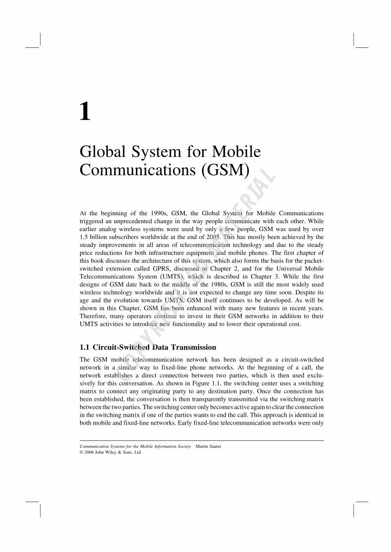
The GSM mobile telecommunication network has been designed as a circuit-switchednetwork in a similar way to fixed-line phone networks. At the beginning of a call, thenetwork establishes a direct connection between two parties, which is then used exclu-sively for this conversation. As shown in Figure 1.1, the switching center uses a switchingmatrix to connect any originating party to any destination party. Once the connection hasbeen established, the conversation is then transparently transmitted via the switching matrixbetween the two parties. The switching center only becomes active again to clear the connectionin the switching matrix if one of the parties wants to end the call. This approach is identical inboth mobile and fixed-line networks. Early fixed-line telecommunication networks were only
Communication Systems for the Mobile Information Society Martin Sauter© 2006 John Wiley & Sons, Ltd
COPYRIG
HTED M
ATERIAL
2 Communication Systems for the Mobile Information Society
Figure 1.1 Switching matrix in a switching center
designed for voice communication for which an analog connection between the parties wasestablished. In the mid-1980s, analog technology was superseded by digital technology in theswitching center. This means that today, calls are no longer sent over an analog line from orig-inator to terminator. Instead, the switching center digitizes the analog signal it receives fromthe subscribers, which are directly attached to it, and forwards the digitized signal to the termi-nating switching center. There, the digital signal is again converted back to an analog signalwhich is then sent over the copper cable to the terminating party. In some countries ISDN (Inte-grated Services Digital Network) lines are quite popular. With this system, the transmission isfully digital and the conversion back into an analog audio signal is done directly in the phone.
GSM reuses much of the fixed-line technology that was already available at the timethe standards were created. Thus, existing technologies such as switching centers and long-distance communication equipment were used. The main development for GSM was themeans to wirelessly connect the subscribers to the network. In fixed-line networks, subscriberconnectivity is very simple as only two dedicated wires are necessary per user. In a GSMnetwork, however, the subscribers are mobile and can change their location at any time.Thus, it is not always possible to use the same input and output in the switching matrix fora user as in fixed-line networks.
As a mobile network consists of many switching centers, with each covering a certaingeographical area, it is not even possible to predict in advance which switching center a callshould be forwarded to for a certain subscriber. This means that the software for subscribermanagement and routing of calls of fixed-line networks cannot be used for GSM. Instead ofa static call-routing mechanism, a flexible mobility management architecture is necessary inthe core network, which needs to be aware of the current location of the subscriber and isthus able to route calls to the subscribers at any time.
It is also necessary to be able to flexibly change the routing of an ongoing call as asubscriber can roam freely and thus might leave the coverage area of the radio transmitter

Global System for Mobile Communications (GSM) 3
Operating system of the switchingcenter
Switching and signaling software
Fixed line subscriber and callcontrol
Mobile subscriber managementMobility managementCall control
Operating system of the switching center
Switching and signaling software
Figure 1.2 Necessary software changes to adapt a fixed-line switching center for a wireless network
of the network over which the call was established. While there is a big difference in thesoftware of a fixed and a mobile switching center, the hardware as well as the lower layersof the software which are responsible for example for the handling of the switching matrixare mostly identical. Therefore, most telecommunication equipment vendors like Siemens,Nortel, Ericsson, Nokia, or Alcatel offer their switching center hardware both for fixed-lineas well as for mobile networks. Only the software in the switching center decides if thehardware is used in a fixed or mobile network (see Figure 1.2).
1.2 Standards
As many telecom companies compete globally for orders of telecommunication networkoperators, standardization of interfaces and procedures is necessary. Without standards, whichare defined by the International Telecommunication Union (ITU), it would not be possibleto make phone calls internationally and network operators would be bound to the supplierthey initially select for the delivery of their network components. One of the most importantITU standards discussed in Section 1.4 is the signaling system number 7 (SS-7), which isused for call routing. Many ITU standards, however, only represent the smallest commondenominator as most countries have specified their own national extensions. In practice, thisincurs a high cost for software development for each country as a different set of extensionsneeds to be implemented in order for a vendor to be able sell its equipment. Furthermore,the interconnection of networks of different countries is complicated by this.
GSM, for the first time, set a common standard for Europe for wireless networks, whichhas also been adopted by many countries outside Europe. This is the main reason whysubscribers can roam in GSM networks across the world that have roaming agreements witheach other. The common standard also substantially reduces research and development costsas hardware and software can now be sold worldwide with only minor adaptations for thelocal market. The European Telecommunication Standards Institute (ETSI), which is alsoresponsible for a number of other standards, was the main body responsible for the creationof the GSM standard. The ETSI GSM standards are composed of a substantial number ofstandards documents each called a technical specification (TS), which describe a particularpart of the system. In the following chapters, many of those specifications will be referencedand can thus be used for further information about a specific topic. All standards are freelyavailable on the Internet at http://www.etsi.org [1] or at http://www.3gpp.org [2], which is
4 Communication Systems for the Mobile Information Society
the organization that took over the standards maintenance and enhancement at the beginningof the UMTS standardization as described in Chapter 3.
1.3 Transmission Speeds
The smallest transmission speed unit in a telecommunication network is the digital signallevel 0 (DS0) channel. It has a fixed transmission speed of 64 kbit/s. Such a channel can beused to transfer voice or data and thus it is usually not called a speech channel but simplyreferred to as a user data channel.
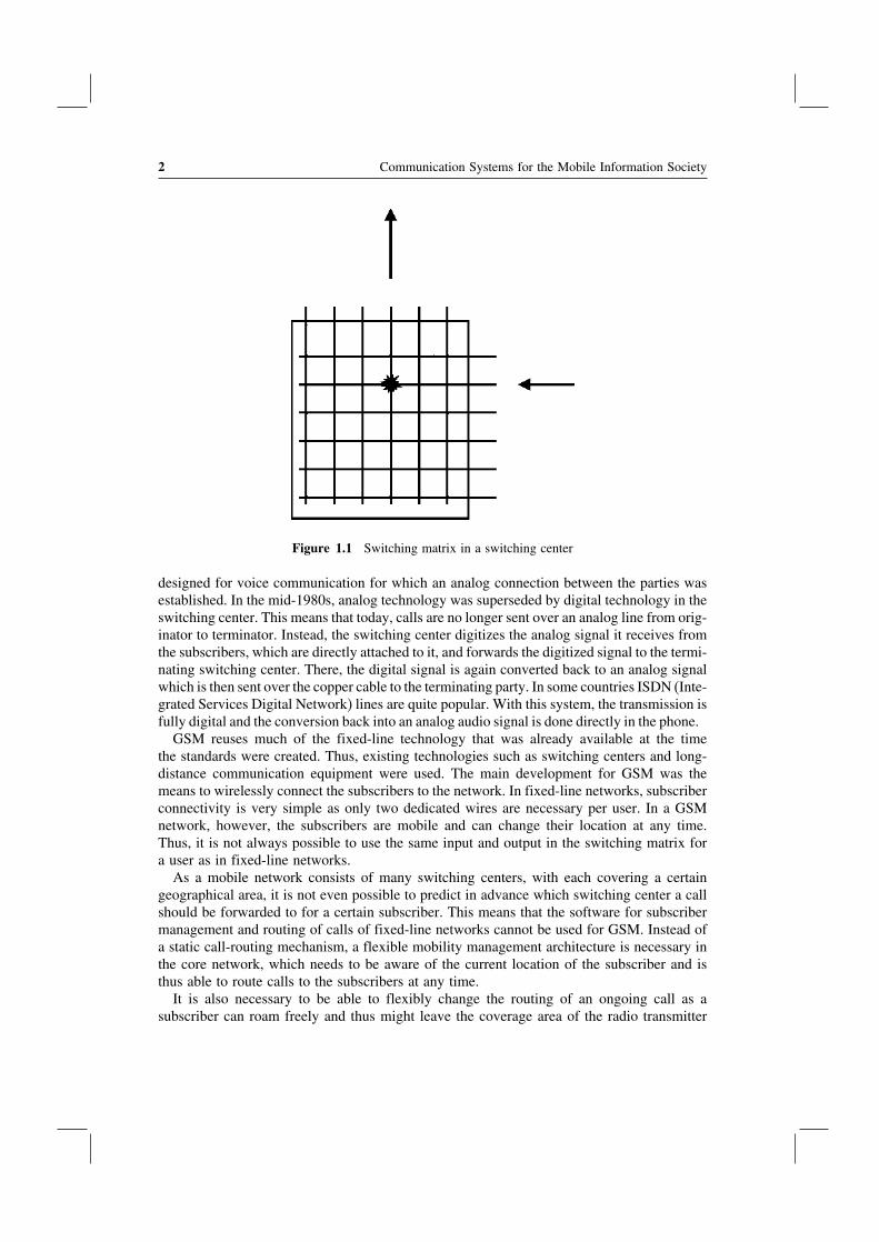
The reference unit of a telecommunication network is an E-1 connection in Europe and aT-1 connection in the United States, which use either a twisted pair or coaxial copper cable.The gross data rate of an E-1 connection is 2.048 Mbit/s and 1.544 Mbit/s for a T-1. An E-1 isdivided into 32 timeslots of 64 kbit/s each while a T-1 is divided into 24 timeslots of 64 kbit/seach. One of the timeslots is used for synchronization which means that 31 timeslots foran E-1 or 23 timeslots for a T-1 respectively can be used to transfer data. In practice, only29 or 30 timeslots are used for user data transmission while the rest (usually one or two)are used for SS-7 signaling data (see Figure 1.3). More about SS-7 can be found in Section 1.4.
Most of the time a single E-1 connection with 31 DS0s is not enough to connect twoswitching centers with each other. In this case E-3 connections can be used, which arealso carried over twisted pair or coaxial cables. An E-3 connection is defined at a speed of34.368 Mbit/s, which corresponds to 512 DS0s.
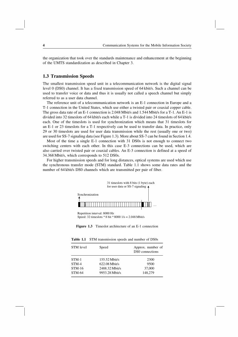
For higher transmission speeds and for long distances, optical systems are used which usethe synchronous transfer mode (STM) standard. Table 1.1 shows some data rates and thenumber of 64 kbit/s DS0 channels which are transmitted per pair of fiber.
Synchronization
31 timeslots with 8 bits (1 byte) eachfor user data or SS-7 signaling
Repetition interval: 8000 Hz Speed: 32 timeslots * 8 bit * 8000 1/s = 2.048 Mbit/s
…
Figure 1.3 Timeslot architecture of an E-1 connection
Table 1.1 STM transmission speeds and number of DS0s
STM level Speed Approx. number ofDS0 connections
STM-1 155.52 Mbit/s 2300STM-4 622.08 Mbit/s 9500STM-16 2488.32 Mbit/s 37,000STM-64 9953.28 Mbit/s 148,279

Global System for Mobile Communications (GSM) 5
1.4 The Signaling System Number 7
For establishing, maintaining, and clearing a connection, signaling information needs to beexchanged between the end user and network devices. In the fixed-line network, analogphones signal their connection request when the receiver is lifted off the hook and by dialinga phone number which is sent to the network either via pulses (pulse dialing) or via tonedialing which is called dual tone multi frequency (DTMF) dialing. With fixed-line ISDNphones and GSM mobile phones the signaling is done via a dedicated signaling channel, andinformation such as the destination phone number is sent via messages.
If several components in the network are involved in the call establishment, for exampleif originating and terminating parties are not connected to the same switching center, it isalso necessary that the different nodes in the network exchange information with each other.This signaling is transparent for the user and a protocol called the signaling system number7 (SS-7) is used for this purpose. SS-7 is also used in GSM networks and the standard hasbeen enhanced by ETSI in order to be able to fulfill the special requirements of mobilenetworks, for example subscriber mobility management.
The SS-7 standard defines three basic types of network nodes:
• Service switching points (SSPs) are switching centers that are more generally referredto as network elements which are able to establish, transport, or forward voice and dataconnections.
• Service control points (SCPs) are databases and application software that can influencethe establishment of a connection. In a GSM network, SCPs can be used for example forstoring the current location of a subscriber. During call establishment to a mobile subscriberthe switching centers query the database for the current location of the subscriber in orderto be able to forward the call. More about this procedure can be found in Section 1.6.3about the home location register.
• Signaling transfer points (STPs) are responsible for the forwarding of signaling messagesbetween SSPs and SCPs as not all network nodes have a dedicated link to all other nodesof the network. The principal functionality of an STP can be compared to an IP routerin the Internet, which also forwards packets to different branches of the network. UnlikeIP routers however, STPs only forward signaling messages which are necessary for theestablishing, maintaining, and clearing of a call. The calls themselves are directly carriedon dedicated links between the SSPs.
Figure 1.4 shows the general structure of an SS-7 circuit-switched telecommunicationnetwork and how the nodes described above are interconnected with each other.
1.4.1 The SS-7 Protocol Stack
SS-7 comprises a number of protocols and layers. A well-known model for describingtelecommunication protocols and different layers is the OSI 7 layer model which is used inFigure 1.5 to show the layers on which the different SS-7 protocols reside.
The message transfer part 1 (MTP-1) protocol describes the physical properties of thetransmission medium on layer 1 of the OSI model. Thus, this layer is also called the physicallayer. Properties that are standardized in MTP-1 are for example the definition of the differentkinds of cables that can be used to carry the signal, signal levels, and transmission speeds.

6 Communication Systems for the Mobile Information Society
Figure 1.4 An SS-7 network with an STP, two SCP databases, and three switching centers
Figure 1.5 Comparison of the SS-7, OSI, and TCP/IP protocol stacks
On layer 2, the data link layer, messages are framed into packets and a start and stopidentification at the beginning and end of each packet is inserted into the data stream so thereceiver is able to detect where a message ends and a new message begins.
Layer 3 of the OSI model, which is called the network layer, is responsible for packetrouting. In order to enable network nodes to forward incoming packets to other nodes, eachpacket gets a source and destination address on this layer. This is done by the MTP-3 protocolof the SS-7 stack. For readers who are already familiar with the TCP/IP protocol stack itmay be noted at this point that the MTP-3 protocol fulfills the same tasks as the IP protocol.Instead of IP addresses, however, the MTP-3 protocol uses so-called point codes to identifythe source and the destination of a message.
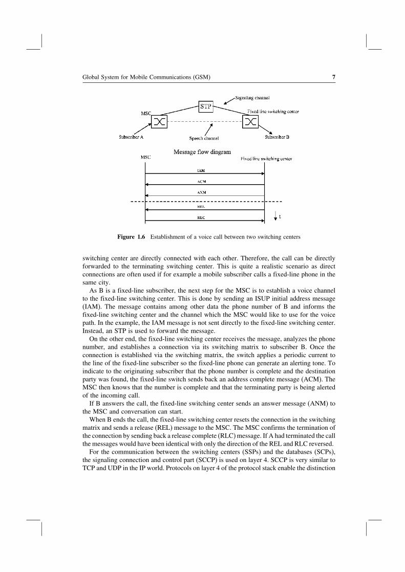
A number of different protocols are used on layers 4 to 7 depending on the application.If a message needs to be sent for the establishment or clearing of a call the ISDN user part(ISUP) protocol is used. Figure 1.6 shows how a call is established between two partiesby using ISUP messages. In the example, party A is a mobile subscriber while party B isa fixed-line subscriber. Thus, A is connected to the network via a mobile switching center(MSC) while B is connected via a fixed-line switching center.
In order to call B, the phone number of B is sent by A to the MSC. The MSC thenanalyzes the national destination code of the phone number, which usually comprises thefirst two to four digits of the number, and detects that the number belongs to a subscriberin the fixed-line network. In the example shown in Figure 1.6, the MSC and the fixed-line
Global System for Mobile Communications (GSM) 7
Figure 1.6 Establishment of a voice call between two switching centers
switching center are directly connected with each other. Therefore, the call can be directlyforwarded to the terminating switching center. This is quite a realistic scenario as directconnections are often used if for example a mobile subscriber calls a fixed-line phone in thesame city.
As B is a fixed-line subscriber, the next step for the MSC is to establish a voice channelto the fixed-line switching center. This is done by sending an ISUP initial address message(IAM). The message contains among other data the phone number of B and informs thefixed-line switching center and the channel which the MSC would like to use for the voicepath. In the example, the IAM message is not sent directly to the fixed-line switching center.Instead, an STP is used to forward the message.
On the other end, the fixed-line switching center receives the message, analyzes the phonenumber, and establishes a connection via its switching matrix to subscriber B. Once theconnection is established via the switching matrix, the switch applies a periodic current tothe line of the fixed-line subscriber so the fixed-line phone can generate an alerting tone. Toindicate to the originating subscriber that the phone number is complete and the destinationparty was found, the fixed-line switch sends back an address complete message (ACM). TheMSC then knows that the number is complete and that the terminating party is being alertedof the incoming call.
If B answers the call, the fixed-line switching center sends an answer message (ANM) tothe MSC and conversation can start.
When B ends the call, the fixed-line switching center resets the connection in the switchingmatrix and sends a release (REL) message to the MSC. The MSC confirms the termination ofthe connection by sending back a release complete (RLC) message. If A had terminated the callthe messages would have been identical with only the direction of the REL and RLC reversed.
For the communication between the switching centers (SSPs) and the databases (SCPs),the signaling connection and control part (SCCP) is used on layer 4. SCCP is very similar toTCP and UDP in the IP world. Protocols on layer 4 of the protocol stack enable the distinction

8 Communication Systems for the Mobile Information Society
of different applications on a single system. TCP and UDP use ports to do this. If a PC forexample is used as a web server and FTP server at the same time, both applications wouldbe accessed over the network via the same IP address. However, while the web server can bereached via port 80, the FTP server waits for incoming data on port 21. Therefore, it is quiteeasy for the network protocol stack to decide which application to forward incoming datapackets. In the SS-7 world, the task of forwarding incoming messages to the right applicationis done by SCCP. Instead of port numbers, SCCP uses subsystem numbers (SSNs).
For database access, the transaction capability application part (TCAP) protocol has beendesigned as part of the SS-7 family of protocols. TCAP defines a number of different modulesand messages that can be used to query all kinds of different databases in a uniform way.
1.4.2 SS-7 Protocols for GSM
Apart from the fixed-line network SS-7 protocols, the following additional protocols weredefined to address the special needs of a GSM network.
The mobile application part (MAP): this protocol has been standardized in 3GPP TS29.002 [3] and is used for the communication between an MSC and the home locationregister (HLR) which maintains subscriber information. The HLR is queried for exampleif the MSC wants to establish a connection to a mobile subscriber. In this case, the HLRreturns the information about the current location of the subscriber. The MSC is then able toforward the call to the responsible switching center for the mobile subscriber by establishinga voice channel between itself and the next hop by using the ISUP message flow that hasbeen shown in Figure 1.6. MAP is also used between two MSCs if the subscriber movesinto the coverage area of a different MSC while a call is ongoing. As shown in Figure 1.7,the MAP protocol uses the TCAP, SCCP, and MTP protocols on lower layers.
The base station subsystem mobile application part (BSSMAP): this protocol is used forthe communication between the MSC and the radio network. Here, the additional protocolis necessary for example to establish a dedicated radio channel for a new connection to amobile subscriber. As BSSMAP is not a database query language like the MAP protocol,BSSMAP is based on SCCP directly instead of using TCAP in between.
Figure 1.7 Enhancement of the SS-7 protocol stack for GSM

Global System for Mobile Communications (GSM) 9
The direct transfer application part (DTAP): this protocol is used between the user’smobile phone, which is also called mobile station (MS), to communicate transparently withthe MSC. In order to establish a voice call the MS sends a setup message to the MSC.As in the example in Section 1.4.1, this message contains among other things the phonenumber of the called subscriber. As it is only the MSC’s task to forward calls, all networknodes between the MS and the MSC forward the message transparently and thus need notunderstand the DTAP protocol.
1.5 The GSM Subsystems
A GSM network is split into three subsystems which are described in more detail below:
• The base station subsystem (BSS), which is also called ‘radio network’, contains all nodesand functionalities that are necessary to wirelessly connect mobile subscribers over theradio interface to the network. The radio interface is usually also referred to as the ‘airinterface’.
• The network subsystem (NSS), which is also called ‘core network’, contains all nodesand functionalities that are necessary for switching of calls, for subscriber managementand mobility management.
• The intelligent network subsystem (IN) comprises SCP databases which add optionalfunctionality to the network. One of the most important optional IN functionality of amobile network is the prepaid service, which allows subscribers to first fund an accountwith a certain amount of money which can then be used for network services like phonecalls, SMS messages, and of course data services via GPRS and UMTS as described inChapters 2 and 3. When a prepaid subscriber uses a service of the network, the responsibleIN node is contacted and the amount the network operator charges for a service is deductedfrom the account in real time.
1.6 The Network Subsystem
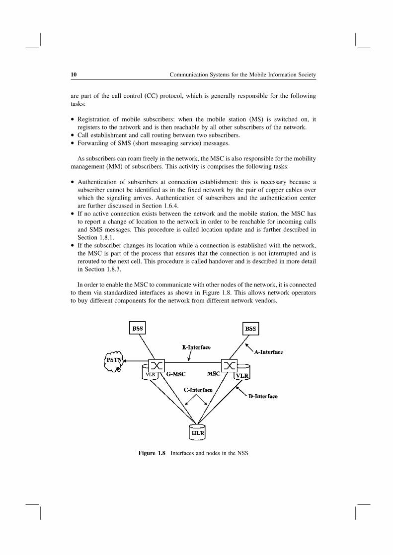
The most important responsibilities of the NSS are call establishment, call control, androuting of calls between different fixed and mobile switching centers and other networks.Other networks are, for example, the national fixed-line network which is also called thepublic standard telephone network (PSTN), international fixed-line networks, other nationaland international mobile networks, and voice over IP (VoIP) networks. Furthermore, the NSSis responsible for subscriber management. The nodes necessary for these tasks are shown inFigure 1.8 and are further described in the next sections.
1.6.1 The Mobile Switching Center (MSC)
The mobile switching center (MSC) is the central element of a mobile telecommunicationnetwork, which is also called a public land mobile network (PLMN) in the standards. Allconnections between subscribers are managed by the MSC and are always routed over theswitching matrix even if two subscribers that have established a connection communicateover the same radio cell. The management activities to establish and maintain a connection
10 Communication Systems for the Mobile Information Society
are part of the call control (CC) protocol, which is generally responsible for the followingtasks:
• Registration of mobile subscribers: when the mobile station (MS) is switched on, itregisters to the network and is then reachable by all other subscribers of the network.
• Call establishment and call routing between two subscribers.• Forwarding of SMS (short messaging service) messages.
As subscribers can roam freely in the network, the MSC is also responsible for the mobilitymanagement (MM) of subscribers. This activity is comprises the following tasks:
• Authentication of subscribers at connection establishment: this is necessary because asubscriber cannot be identified as in the fixed network by the pair of copper cables overwhich the signaling arrives. Authentication of subscribers and the authentication centerare further discussed in Section 1.6.4.
• If no active connection exists between the network and the mobile station, the MSC hasto report a change of location to the network in order to be reachable for incoming callsand SMS messages. This procedure is called location update and is further described inSection 1.8.1.
• If the subscriber changes its location while a connection is established with the network,the MSC is part of the process that ensures that the connection is not interrupted and isrerouted to the next cell. This procedure is called handover and is described in more detailin Section 1.8.3.
In order to enable the MSC to communicate with other nodes of the network, it is connectedto them via standardized interfaces as shown in Figure 1.8. This allows network operatorsto buy different components for the network from different network vendors.
Figure 1.8 Interfaces and nodes in the NSS

Global System for Mobile Communications (GSM) 11
The base station subsystem (BSS), which connects all subscribers to the core network, isconnected to the MSCs via a number of 2 Mbit/s E-1 connections. This interface is called theA-interface. As has been shown in Section 1.4 the BSSMAP and DTAP protocols are usedover the A-interface for communication between the MSC, the BSS, and the mobile stations.As an E-1 connection can only carry 31 channels, many E-1 connections are necessary toconnect an MSC to the BSS. In practice, this means that many E-1s are bundled and sent overoptical connections such as STM-1 to the BSS. Another reason to use an optical connectionis that electrical signals can only be carried over long distances with great effort and it isnot unusual that an MSC is over 100 kilometers away from the next BSS node.
As an MSC only has a limited switching capacity and processing power, a PLMN isusually composed of dozens or even hundreds of independent MSCs. Each MSC thus coversonly a certain area of the network. In order to ensure connectivity beyond the immediatecoverage area of an MSC, E-1s, which are again bundled into optical connections, are usedto interconnect the different MSCs of a network. As a subscriber can roam into the areathat is controlled by a different MSC while a connection is active, it is necessary to changethe route of an active connection to the new MSC (handover). The necessary signalingconnection is called the E-interface. ISUP is used for the establishment of the speech pathbetween different MSCs and the MAP protocol is used for the handover signaling betweenthe MSCs. Further information about the handover process can be found in Section 1.8.3.
The C-interface is used to connect the MSCs of a network with the home location register(HLR) of the mobile network. While the A-and E-interface, described previously, alwaysconsist of signaling and speech path links, the C-interface is a pure signaling link. Speechchannels are not necessary for the C-interface as the HLR is a pure database which cannottaccept or forward calls. Despite being only a signaling interface, E-1 connections are usedfor this interface. All timeslots are used for signaling purposes or are unused.
As has been shown in Section 1.3, a voice connection is carried on a 64 kbit/s E-1 timeslotin a circuit-switched fixed line or mobile network. Before the voice signal can be forwarded,it needs to be digitized. For an analog fixed-line connection this is done in the switchingcenter, while an ISDN fixed-line phone or a GSM mobile phone digitizes the voice signalthemselves.
An analog voice signal is digitized in three steps: in the first step, the bandwidth of theinput signal is limited to 300–3400 Hz in order to be able to carry the signal with the limitedbandwidth of a 64 kbit/s timeslot. Afterwards, the signal is sampled at a rate of 8000 timesa second. The next processing step is the quantization of the samples, which means that theanalog samples are converted into eight-bit digital values that can each have a value from 0to 255. See Figure 1.9.
The higher the volume of the input signal, the higher the amplitude of the sampled valueand its digital representation. In order to be able to also transmit low-volume conversations,the quantization is not linear over the whole input range but only in certain areas. For smallamplitudes of the input signal a much higher range of digital values is used than for highamplitude values. The resulting digital data stream is called a pulse code modulated (PCM)signal. Which volume is represented by which digital eight-bit value is described in theA-law standard for European networks and in the �-law standard in North America.
The use of different standards unfortunately complicates voice calls between networksthat use different standards. Therefore, it is necessary for example to convert a voice signalfor a connection between France and the United States.

12 Communication Systems for the Mobile Information Society
Speech is converted by a microphone into an analog signal
Sample frequency: 8000 Hz300 Hz–3.4 kHz
Bandwidth limited signal
Pulse-amplitudemodulated signal every 125 µs
13 segment curve 256 values, 8 bits
Digitizedspeech signal at 64 kbit/s
Band-pass filter
Sampler Quantitizer
Figure 1.9 Digitization of an analog voice signal
As the MSC controls all connections, it is also responsible for billing. This is done bycreating a billing record for each call which is later transferred to a billing server. The billingrecord contains information like the number of caller and calling party, cell ID of the cellfrom which the call was originated, time of call origination, the duration of the call, etc.Calls for prepaid subscribers are treated differently as the charging is already done while thecall is running. The prepaid billing service is usually implemented on an IN system and noton the MSC as is further described in Section 1.11.
1.6.2 The Visitor Location Register (VLR)
Each MSC has an associated visitor location register (VLR), which holds a record of eachsubscriber that is currently served by the MSC (Figure 1.10). These records are only acopy of the original records, which are stored in the HLR (see Section 1.6.3). The VLR ismainly used to reduce the signaling between the MSC and the HLR. If a subscriber roamsinto the area of an MSC, the data is copied to the VLR of the MSC and is thus locallyavailable for every connection establishment. The verification of the subscriber’s record atevery connection establishment is necessary, as the record contains information about which
Switching center
MSC application
with SSN = 8
VLR application
with SSN = 7
MTP 1–3
SCCP
Incoming signaling messages for VLR and MSC
Figure 1.10 Mobile switching center (MSC) with integrated visitor location register (VLR)
Global System for Mobile Communications (GSM) 13
services are active and from which services the subscriber is barred. Thus, it is possible, forexample, to bar outgoing calls while allowing incoming calls to prevent abuse of the system.While the standards allow implementing the VLR as an independent hardware component,all vendors have implemented the VLR simply as a software component in the MSC. This ispossible because MSC and VLR use different SCCP subsystem numbers (see Section 1.4.1)and can thus run on a single physical node.
When a subscriber leaves the coverage area of an MSC, the subscriber’s record is copiedfrom the HLR to the VLR of the new MSC, and is then removed from the VLR of the previousMSC. The communication with the HLR is standardized in the D-interface specificationwhich is shown together with other MSC interfaces in Figure 1.8.
1.6.3 The Home Location Register (HLR)
The HLR is the subscriber database of a GSM network. It contains a record for eachsubscriber, which contains information about the individually available services.
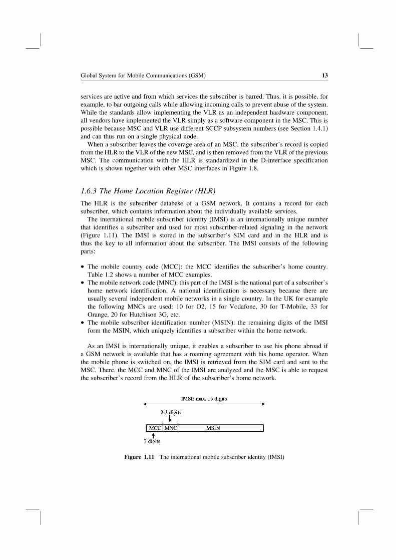
The international mobile subscriber identity (IMSI) is an internationally unique numberthat identifies a subscriber and used for most subscriber-related signaling in the network(Figure 1.11). The IMSI is stored in the subscriber’s SIM card and in the HLR and isthus the key to all information about the subscriber. The IMSI consists of the followingparts:
• The mobile country code (MCC): the MCC identifies the subscriber’s home country.Table 1.2 shows a number of MCC examples.
• The mobile network code (MNC): this part of the IMSI is the national part of a subscriber’shome network identification. A national identification is necessary because there areusually several independent mobile networks in a single country. In the UK for examplethe following MNCs are used: 10 for O2, 15 for Vodafone, 30 for T-Mobile, 33 forOrange, 20 for Hutchison 3G, etc.
• The mobile subscriber identification number (MSIN): the remaining digits of the IMSIform the MSIN, which uniquely identifies a subscriber within the home network.
As an IMSI is internationally unique, it enables a subscriber to use his phone abroad ifa GSM network is available that has a roaming agreement with his home operator. Whenthe mobile phone is switched on, the IMSI is retrieved from the SIM card and sent to theMSC. There, the MCC and MNC of the IMSI are analyzed and the MSC is able to requestthe subscriber’s record from the HLR of the subscriber’s home network.
Figure 1.11 The international mobile subscriber identity (IMSI)

14 Communication Systems for the Mobile Information Society
Table 1.2 Mobile country codes
MCC Country
234 United Kingdom310 United States228 Switzerland208 France262 Germany604 Morocco505 Australia
Figure 1.12 A terminal program can be used to retrieve the IMSI from the SIM card
For information purposes, the IMSI can also be retrieved from the SIM card with a PCand a serial cable that connects to the mobile phone. By using a terminal program suchas HyperTerminal, the mobile can be instructed to return the IMSI by using the ‘at+cimi’command, which is standardized in 3GPP TS 27.007 [4]. Figure 1.12 shows how the IMSIis returned by the mobile phone.
The phone number of the user, which is called the mobile subscriber ISDN number(MSISDN) in the GSM standards, has a length of up to 15 digits and consists of the followingparts:
• The country code is the international code of the subscriber’s home country. The countrycode has one to three digits such as +44 for the UK, +1 for the US, +353 for Ireland.
• The national destination code (NDC) usually represents the code with which the networkoperator can be reached. It is normally three digits in length. It should to be noted thatmobile networks in the US use the same NDCs as fixed-line networks. Thus, it is notpossible for a user to distinguish if he is calling a fixed line or a mobile phone. This

Global System for Mobile Communications (GSM) 15
impacts both billing and routing, as the originating network cannot deduct which tariff toapply from the NDC.
• The remainder of the MSISDN is the subscriber number, which is unique in the network.
There is usually a 1:1 or 1:N relationship in the HLR between the IMSI and the MSISDN.Furthermore, a mobile subscriber is normally assigned only a single MSISDN. However, asthe IMSI is the unique identifier of a subscriber in the mobile network, it is also possible toassign several numbers to a single subscriber.
Another advantage of using the IMSI as the key to all subscriber information instead ofthe MSISDN is that the phone number of the subscriber can be changed without replacingthe user’s SIM card or changing any information on it. In order to change the MSISDN,only the HLR record of the subscriber needs to be changed. In effect, this means that themobile station is not aware of its own phone number. This is not necessary because theMSC automatically adds the user’s MSISDN to the message flow for a mobile-originatedcall establishment so it can be presented to the called party.
Many countries have introduced a functionality called mobile number portability (MNP),which allows a subscriber to keep his MSISDN if he wants to change his mobile networkoperator. This is a great advantage for the subscribers and for competition between the mobileoperators, but also implies that it is no longer possible to discern the mobile network to whichthe call will be routed from the NDC. Furthermore, the introduction of MNP also increasedthe complexity of call routing and billing in both fixed-line and mobile networks, becauseit is no longer possible to use the NDC to decide which tariff to apply to a call. Instead ofa simple call-routing scheme based on the NDC, the networks now have to query a mobilenumber portability database for every call to a mobile subscriber to find out if the call canbe routed inside the network or if it has to be forwarded to a different national mobile network.
Apart from the IMSI and MSISDN, the HLR contains a variety of information about eachsubscriber, such as which services he is allowed to use. Table 1.3 shows a number of ‘basicservices’ that can be activated on a per subscriber basis:
In addition to the basic services described above, the GSM network offers a number ofother services that can also be activated on a per subscriber basis. These services are calledsupplementary services and are shown in Table 1.4.
Table 1.3 Basic services of a GSM network
Basic service Description
Telephony If this basic service is activated, a subscriber can usethe voice telephony services of the network. This canbe partly restricted by other supplementary serviceswhich are described below
Short messaging service (SMS) If activated, a subscriber is allowed to use the SMSData service Different circuit-switched data services can be
activated for a subscriber with speeds of 2.4, 4.8, 9.6,and 14.4 kbit/s data calls
FAX Allows or denies a subscriber the use of the FAXservice that can be used to exchange FAX messageswith fixed-line or mobile terminals

16 Communication Systems for the Mobile Information Society
Table 1.4 Supplementary services of a GSM network
Supplementary service Description
Call forwardunconditional (CFU)
If this service is configured, a number can be configured to which allincoming calls are forwarded immediately [5]. This means that the mobilephone will not even be notified of the incoming call even if it isswitched on
Call forward busy(CFB)
This service allows a subscriber to define a number to which calls areforwarded if he is already engaged in a call when a second call comes in
Call forward no reply(CFNRY)
If this service is activated, it is possible to forward the call to auser-defined number if the subscriber does not answer the call within acertain time. The subscriber can change the number to which to forwardthe call to as well as the timeout value (e.g. 25 seconds)
Call forward notreachable (CFNR)
This service forwards the call if the mobile phone is attached to thenetwork but is not reachable momentarily (e.g. temporary loss of networkcoverage)
Barring of alloutgoing calls(BAOC)
This functionality can be activated by the network operator if, for example,the subscriber has not paid his monthly invoice in time. It is also possiblefor the network operator to allow the subscriber to change the state of thisfeature together with a PIN (personal identification number) so thesubscriber can lend the phone to another person for incoming calls only [6]
Barring of allincoming calls(BAIC)
Same functionality as provided by BAOC for incoming calls [6]
Call waiting (CW) This feature allows signaling an incoming call to a subscriber while he isalready engaged on another call [7]. The first call can then be put on holdto accept the incoming call. The feature can be activated or barred by theoperator and switched on or off by the subscriber
Call hold (HOLD) This functionality is used to accept an incoming call during an alreadyactive call or to start a second call [7]
Calling lineidentificationpresentation (CLIP)
If activated by the operator for a subscriber, the functionality allows theswitching center to forward the number of the caller
Calling lineidentificationrestriction (CLIR)
If allowed by the network, the caller can instruct the network not to showhis phone number to the called party
Connected linepresentation (COLP)
Shows the calling party the MSISDN to which a call is forwarded, if callforwarding is active at the called party side
Connected linepresentationrestriction (COLR)
If COLR is activated at the called party, the calling party will not benotified of the MSISDN the call is forwarded to
Multi party (MPTY) Allows subscribes to establish conference bridges with up to sixsubscribers [8]
Global System for Mobile Communications (GSM) 17
Most supplementary services can be activated by the network operator on a per subscriberbasis and allow the operator to charge an additional monthly fee for some services if desired.Other services, like multi party, can be charged on a per use basis. Most services can beconfigured by the subscriber via a menu on the mobile phone. The menu, however, is justa graphical front end for the user and the mobile phone translates the user’s commands intonumerical strings which start with a ‘∗’ character. These strings are then sent to the networkby using an unstructured supplementary service data (USSD) message. The codes are stan-dardized in 3GPP TS 22.030 [9] and are thus identical in all networks. As the menu is onlya front end for the USSD service, the user can also input the USSD strings himself via thekeypad. After pressing the ‘send’ button, which is usually the button that is also used to starta phone call after typing in a phone number, the mobile phone sends the string to the HLR viathe MSC, where the string is analyzed and the requested operation is performed. For example,call forwarding to another phone (e.g. 0782 192 8355), while a user is already engaged inanother call (CFB), is activated with the following string: ∗∗67∗07821928355# + call button.
1.6.4 The Authentication Center
Another important part of the HLR is the authentication center (AC). The AC contains anindividual key per subscriber (Ki) which is a copy of the Ki in the SIM card of the subscriber.As the Ki is secret, it is stored in the AC and especially on the SIM card in a way thatprevents it being read directly.
For many operations in the network, for instance during the establishment of a call, thesubscriber is identified by using this key. Thus it can be ensured that the subscriber’s identityis not misused by a third party. Figures 1.13 and 1.14 show how the authentication processis performed.
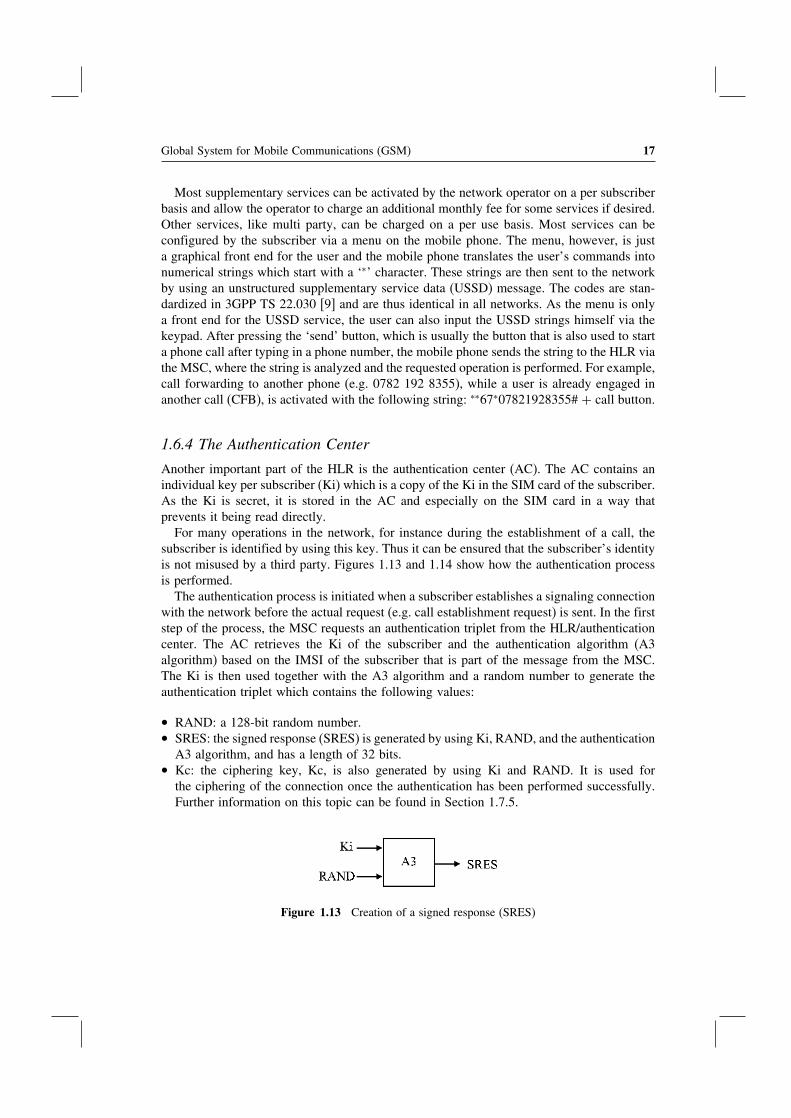
The authentication process is initiated when a subscriber establishes a signaling connectionwith the network before the actual request (e.g. call establishment request) is sent. In the firststep of the process, the MSC requests an authentication triplet from the HLR/authenticationcenter. The AC retrieves the Ki of the subscriber and the authentication algorithm (A3algorithm) based on the IMSI of the subscriber that is part of the message from the MSC.The Ki is then used together with the A3 algorithm and a random number to generate theauthentication triplet which contains the following values:
• RAND: a 128-bit random number.• SRES: the signed response (SRES) is generated by using Ki, RAND, and the authentication
A3 algorithm, and has a length of 32 bits.• Kc: the ciphering key, Kc, is also generated by using Ki and RAND. It is used for
the ciphering of the connection once the authentication has been performed successfully.Further information on this topic can be found in Section 1.7.5.
Figure 1.13 Creation of a signed response (SRES)

18 Communication Systems for the Mobile Information Society
t
SIM/Mobile station MSC HLR/AC
Connection establishment (e.g. location update or call establishment)
MAP: Send authentication triplets (IMSI)
Send authentication triplets ack. (RAND, SRES, Kc)DTAP: Authentication request
(RAND)
DTAP: Authentication response (SRES*)
SRES* = SRES?
Connection is maintained, activation of ciphering
Figure 1.14 Message flow during the authentication of a subscriber
RAND, SRES, and Kc are then returned to the MSC, which then performs the authen-tication of the subscriber. It is important to note that the secret Ki key never leaves theauthentication center.
In order to speed up subsequent connection establishments the AC usually returns severalauthentication triplets per request. These are buffered by the MSC/VLR and are used duringthe next connection establishments.
In the next step, the MSC sends the RAND inside an authentication request message tothe mobile station. The terminal forwards the RAND to the SIM card which then uses theKi and the authentication A3 algorithm to generate a signed response (SRES∗). The SRES∗
is returned to the mobile station and then sent back to the MSC inside an authenticationresponse message. The MSC then compares SRES and SRES∗ and if they are equal thesubscriber is authenticated and allowed to proceed with the communication.
As the secret key, Ki, is not transmitted over any interface that could be eavesdroppedon, it is not possible for a third party to correctly calculate an SRES. As a fresh randomnumber is used for the next authentication, it is also pointless to intercept the SRES∗
and use it for another authentication. A detailed description of the authentication proce-dure and many other procedures between the mobile station and the core network can befound in [10].
Figure 1.15 shows some parts of an authentication request and an authentication responsemessage. Apart from the format of RAND and SRES, it is also interesting to note thedifferent protocols which are used to encapsulate the message (see Section 1.4.2).

Global System for Mobile Communications (GSM) 19
Extract of a decoded Authentication Request messageSCCP MSG: Data Form 1DEST. REF ID: 0B 02 00DTAP MSG LENGTH: 19PROTOCOL DISC.: Mobility ManagementDTAP MM MSG: Auth. RequestCiphering Key Seq.: 0RAND in hex: 12 27 33 49 11 00 98 45
87 49 12 51 22 89 18 81 (16 byte = 128 bit)
Extract of a decoded Authentication Response messageSCCP MSG: Data Form 1DEST. REF ID: 00 25 FEDTAP MSG LENGTH: 6PROTOCOL DISC.: Mobility ManagementDTAP MM MSG: Auth. ResponseSRES in hex: 37 21 77 61 (4 byte = 32 bit)
Figure 1.15 Authentication between network and mobile station
1.6.5 The Short Messaging Service Center (SMSC)
Another important network element is the short message service center (SMSC) which isused to store and forward short messages. The short messaging service was only introducedabout four years after the first GSM networks went into operation as add on and has beenspecified in 3GPP TS 23.040 [11]. Most industry observers were quite skeptical at the timeas the general opinion was that if it is needed to convey some information, it is done bycalling someone rather than to cumbersomely type in a text message on the small keypad.However, they were proven wrong and today most GSM operators generate over 15% oftheir revenue from the short messaging service alone with a total number of over 25 billionSMS messages exchanged annually in the United Kingdom.
The short messaging service can be used for person-to-person messaging as well as fornotification purposes of received email messages or a new call forwarded to the voice mailsystem. The transfer method for both cases is identical.
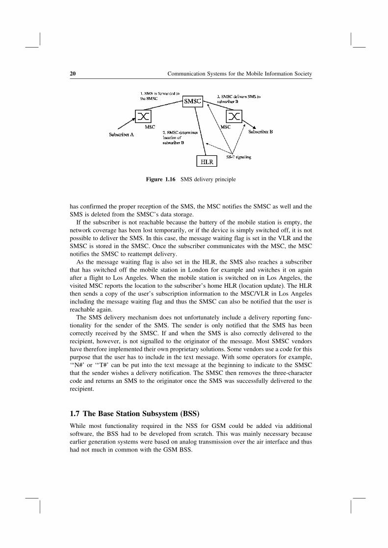
The sender of an SMS prepares the text for the message and then sends the SMS via asignaling channel to the MSC. As a signaling channel is used, an SMS is just an ordinaryDTAP SS-7 message and thus, apart from the content, very similar to other DTAP messages,such as a location update message or a setup message to establish a voice call. Apart from thetext, the SMS message also contains the MSISDN of the destination party and the addressof the SMSC which the mobile station has retrieved from the SIM card. When the MSCreceives an SMS from a subscriber it transparently forwards the SMS to the SMSC. As themessage from the mobile station contains the address of the subscriber’s SMSC, internationalroaming is possible and the foreign MSC can forward the SMS to the home SMSC withoutthe need for an international SMSC database. See Figure 1.16.
In order to deliver a message, the SMSC analyses the MSISDN of the recipient andretrieves its current location (the responsible MSC) from the HLR. The SMS is then forwardedto the responsible MSC. If the subscriber is currently attached, the MSC tries to contact themobile station and if an answer is received, the SMS is forwarded. Once the mobile station
20 Communication Systems for the Mobile Information Society
Figure 1.16 SMS delivery principle
has confirmed the proper reception of the SMS, the MSC notifies the SMSC as well and theSMS is deleted from the SMSC’s data storage.
If the subscriber is not reachable because the battery of the mobile station is empty, thenetwork coverage has been lost temporarily, or if the device is simply switched off, it is notpossible to deliver the SMS. In this case, the message waiting flag is set in the VLR and theSMSC is stored in the SMSC. Once the subscriber communicates with the MSC, the MSCnotifies the SMSC to reattempt delivery.
As the message waiting flag is also set in the HLR, the SMS also reaches a subscriberthat has switched off the mobile station in London for example and switches it on againafter a flight to Los Angeles. When the mobile station is switched on in Los Angeles, thevisited MSC reports the location to the subscriber’s home HLR (location update). The HLRthen sends a copy of the user’s subscription information to the MSC/VLR in Los Angelesincluding the message waiting flag and thus the SMSC can also be notified that the user isreachable again.
The SMS delivery mechanism does not unfortunately include a delivery reporting func-tionality for the sender of the SMS. The sender is only notified that the SMS has beencorrectly received by the SMSC. If and when the SMS is also correctly delivered to therecipient, however, is not signalled to the originator of the message. Most SMSC vendorshave therefore implemented their own proprietary solutions. Some vendors use a code for thispurpose that the user has to include in the text message. With some operators for example,‘∗N#’ or ‘∗T#’ can be put into the text message at the beginning to indicate to the SMSCthat the sender wishes a delivery notification. The SMSC then removes the three-charactercode and returns an SMS to the originator once the SMS was successfully delivered to therecipient.
1.7 The Base Station Subsystem (BSS)
While most functionality required in the NSS for GSM could be added via additionalsoftware, the BSS had to be developed from scratch. This was mainly necessary becauseearlier generation systems were based on analog transmission over the air interface and thushad not much in common with the GSM BSS.

Global System for Mobile Communications (GSM) 21
1.7.1 Frequency Bands
In Europe, GSM was initially only specified for operation in the 900 MHz band between890–915 MHz in the uplink direction and between 935–960 MHz in the downlink direction(Figure 1.17). ‘Uplink’ refers to the transmission from the mobile station to the network and‘downlink’ to the transmission from the network to the mobile station. The bandwidth of25 MHz is split into 125 channels with a bandwidth of 200 kHz each.
It soon became apparent that the number of available channels was not sufficient to copewith the growing demand in many European countries. Therefore, the regulating bodiesassigned an additional frequency range for GSM which uses the frequency band from1710–1785 MHz for the uplink and 1805–1880 for the downlink. Instead of a total bandwidthof 25 MHz as in the 900 MHz range, the 1800 MHz band offers 75 MHz of bandwidthwhich corresponds to 375 additional channels. The functionality of GSM is identical on bothfrequency bands, with the channel numbers, also referred to as the absolute radio frequencychannel numbers (ARFCNs), being the only difference. See Table 1.5.
While GSM was originally intended only as a European standard, the system soon spread tocountries in other parts of the globe. In countries outside Europe, GSM sometimes competeswith other technologies, such as CDMA. Today, only a few countries, like Japan and SouthKorea, are not covered by GSM systems. However, some of the operators in these countriesoperate W-CDMA UMTS networks (see Chapter 3). Therefore, GSM/UMTS subscriberswith dual-mode phones can also roam in these countries.
In North America, analog mobile networks continued to be used for some time beforesecond-generation networks, with GSM being one of the technologies used, were introduced.Unfortunately, however, the 900 MHz as well as the 1800 MHz band were already in useby other systems and thus the North American regulating body chose to open frequencybands for the new systems in the 1900 MHz band and later on in the 850 MHz band. Thedisadvantage of this approach is that many US GSM mobile phones cannot be used in Europe
Figure 1.17 GSM uplink and downlink in the 900 MHz frequency band
Table 1.5 GSM frequency bands
Band ARFCN Uplink (MHz) Downlink (MHz)
GSM 900 (Primary) 0–124 890–915 935–960GSM 900 (Extended) 975–1023, 0–124 880–915 925–960GSM 1800 512–885 1710–1785 1805–1880GSM 1900 (North America) 512–810 1850–1910 1930–1990GSM 850 (North America) 128–251 824–849 869–894GSM-R 0–124, 955–1023 876–915 921–960
22 Communication Systems for the Mobile Information Society
and vice versa. Fortunately, many new GSM and UMTS phones support the US frequencybands as well as the European frequency bands, which are also used in most countries inother parts of the world. These tri-band or quad-band phones thus enable a user to trulyroam globally.
The GSM standard is also used by railway communication networks in Europe and otherparts of the world. For this purpose, GSM was enhanced to support a number of privatemobile radio and railway specific functionalities and is known as GSM-R. The additionalfunctionalities include:
• The voice group call service (VGCS): this service offers a circuit-switched walkie-talkiefunctionality to allow subscribers that have registered to a VGCS group to communicatewith all other subscribers in the area who have also subscribed to the group. In order totalk, the user has to press a push to talk button. If no other subscriber holds the uplink, thenetwork grants the request and blocks the uplink for all other subscribers while the push totalk button is pressed. The VGCS service is very efficient especially if many subscribersparticipate in a group call, as all mobile stations that participate in the group call listento the same timeslot in downlink direction. Further information about this service can befound in 3GPP TS 43.068 [12].
• The voice broadcast service (VBS): same as VGCS with the restriction that only theoriginator of the call is allowed to speak. Further information about this service can befound in 3GPP TS 43.069 [13].
• Enhanced multi level precedence and preemption (eMLPP): this functionality, which isspecified in 3GPP TS 23.067 [14], is used to attach a priority to a point-to-point, VBS,or VGCS call. This enables the network and the mobile stations to automatically preemptongoing calls for higher priority calls to ensure that emergency calls (e.g. a personhas fallen on the track) is not blocked by lower priority calls and a lack of resources(e.g. because no timeslots are available).
As GSM-R networks are private networks, it has been decided to assign a private frequencyband in Europe for this purpose which is just below the public 900 MHz GSM band. Touse GSM-R, mobile phones need to be slightly modified to be able to send and receivein this frequency range. This requires only minor software and hardware modifications. Inorder to be also able to use the additional functionalities described above, further exten-sions of the mobile station software are necessary. More about GSM-R can be found athttp://gsm-r.uic.asso.fr [15].
1.7.2 The Base Transceiver Station (BTS)
Base stations, which are also called base transceiver stations (BTSs), are the most visiblenetwork elements of a GSM system (Figure 1.18). Compared to fixed-line networks, the basestations replace the wired connection to the subscriber with a wireless connection which isalso referred to as the air interface. The base stations are also the most numerous componentsof a mobile network as according to press reports each wireless operator in the UK forexample has well over 10,000 base stations.
In theory, a base station can cover an area with a radius of up to 35 km. This area isalso called a cell. As a base station can only serve a limited number of simultaneous users,

Global System for Mobile Communications (GSM) 23
Figure 1.18 A typical antenna of a GSM base station. The optional microwave directional antenna(round antenna at the bottom of the mast) connects the base station with the GSM network
cells are much smaller in practice especially in dense urban environments. There, cells coverareas with a radius between 3 and 4 km in residential and business areas, and down to onlyseveral 100 m and minimal transmission power in heavily frequented areas like shoppingcenters and downtown streets. Even in rural areas, a cell’s coverage area is usually less then15 km as the transmission power of the mobile station of one or two watts is the limitingfactor in this case.
As the emissions of different base stations of the network must not interfere with each other,all neighboring cells have to send on different frequencies. As can be seen in Figure 1.19, asinge base station usually has quite a number of neighboring sites. Therefore, only a limitednumber of different frequencies can be used per base station in order to increase capacity.
To increase the capacity of a base station, the coverage area is usually split into two orthree sectors which are then covered on different frequencies by a dedicated transmitter.
Adjacent cells whichhave to send on a differentfrequency
Neighbor cellswhich are furtheraway
Figure 1.19 Cellular structure of a GSM network

24 Communication Systems for the Mobile Information Society
Figure 1.20 Sectorized cell configurations
This allows the reuse of frequencies in two-dimensional space better than if only a singlefrequency was used for the whole base station. Each sector of the base station thereforeforms its own independent cell (Figure 1.20).
1.7.3 The GSM Air Interface
The transmission path between the BTS and the mobile terminal is referred to in theGSM specifications as the air interface or the Um interface. To allow the base stationto communicate with several subscribers simultaneously, two methods are used. The firstmethod is frequency division multiple access (FDMA) which means that users communicatewith the base station on different frequencies. The second method used is time divisionmultiple access (TDMA). See Figure 1.21. GSM uses carrier frequencies with a bandwidthof 200 kHz over which up to eight subscribers can communicate with the base stationsimultaneously.
Subscribers are time multiplexed by dividing the carrier into frames with durations of4.615 ms. Each frame contains eight physically independent timeslots, each for communica-tion with a different subscriber. The timeframe of a timeslot is called a burst and the burstduration is 577 microseconds. If a mobile station is allocated timeslot number two for a voicecall for example, the mobile station will send and receive only during this burst. Afterwards,it has to wait until the next frame before it is allowed to send again.
By combining the two multiple access schemes it is possible to approximately calculatethe total capacity of a base station. For the following example it is assumed that the basestation is split into three sectors and each sector is covered by an independent cell. Eachcell is equipped with two transmitters and receivers, a configuration that is used quite often.In each sector, 2 × 8 = 16 timeslots are thus available. Two timeslots are usually assignedfor signaling purposes which leaves 14 timeslots per sector for user channels. Let us furtherassume that four timeslots or more are used for the packet-switched GPRS service (seeChapter 2). Therefore, 10 timeslots are left for voice calls per sector, which amounts to 30
Figure 1.21 A GSM TDMA frame

Global System for Mobile Communications (GSM) 25
channels for all sectors of the base station. In other words this means that 30 subscribers cancommunicate simultaneously per base station.
A single BTS, however, provides service for a much higher number of subscribers, as theydo not all communicate at the same time. Mobile operators, therefore, base their networkdimensioning on a theoretical call profile model in which the number of minutes a subscriberstatistically uses the system per hour is one of the most important parameters. A commonlyused value for the number of minutes a subscriber uses the system per hour is one minute.This means that a base station is able to provide service for 60 times the number of activesubscribers. In this example a base station with 30 channels is therefore able to provideservice for about 1800 subscribers.
This number is quite realistic as the following calculation shows: Vodafone Germany hada subscriber base of about 25 million in 2005. If this value is divided by the number ofsubscribers per cell, the total number of base stations required to serve such a large subscriberbase can be determined. With our estimation above, the number of base stations required forthe network would be about 14,000. This value is quite accurate and in line with numberspublished by the operator.
Each burst of a TDMA frame is divided into a number of different sections as shownin Figure 1.22. Each burst is encapsulated by a guard time in which no data is sent. Thisis necessary because the distance of the different subscribers relative to the base stationcan change while they are active. As airwaves ‘only’ propagate through space at the speedof light, the signal of a far away subscriber takes a longer time to reach the base stationcompared to a subscriber that is closer to the base station. In order to prevent any overlap,guard times were introduced. These parts of the burst are very short, as the network activelycontrols the timing advance of the mobile station. More about this topic can be found below.
The training sequence in the middle of the burst always contains the same bit pattern.It is used to compensate for interference caused for example by reflection, absorption, andmulti-path propagation. On the receiver side these effects are countered by comparing thereceived signal to the training sequence and thus adapting the analog filter parameters forthe signal. The filter parameters calculated this way can then be used to modify the rest ofthe signal and thus to better recreate the original signal.
At the beginning and end of each burst, another well-known bit pattern is sent to enablethe receiver to detect the beginning and end of a burst correctly. These fields are called‘tails’. The actual user data of the burst, i.e. the digitized voice signal, is sent in the twouser data fields with a length of 57 bits each. This means, that a 577-microsecond bursttransports 114 bits of user data. Finally, each frame contains two bits to the left and right ofthe training sequence which are called ‘stealing bits’. These bits indicate if the data fields
Figure 1.22 A GSM burst
26 Communication Systems for the Mobile Information Society
contain user data or are used (‘stolen’) for urgent signaling information. User data of burstswhich carry urgent signaling information, however, is lost. As shown below, the speechdecoder is able to cope with short interruptions of the data stream quite well and thus arenot normally audible to the user.
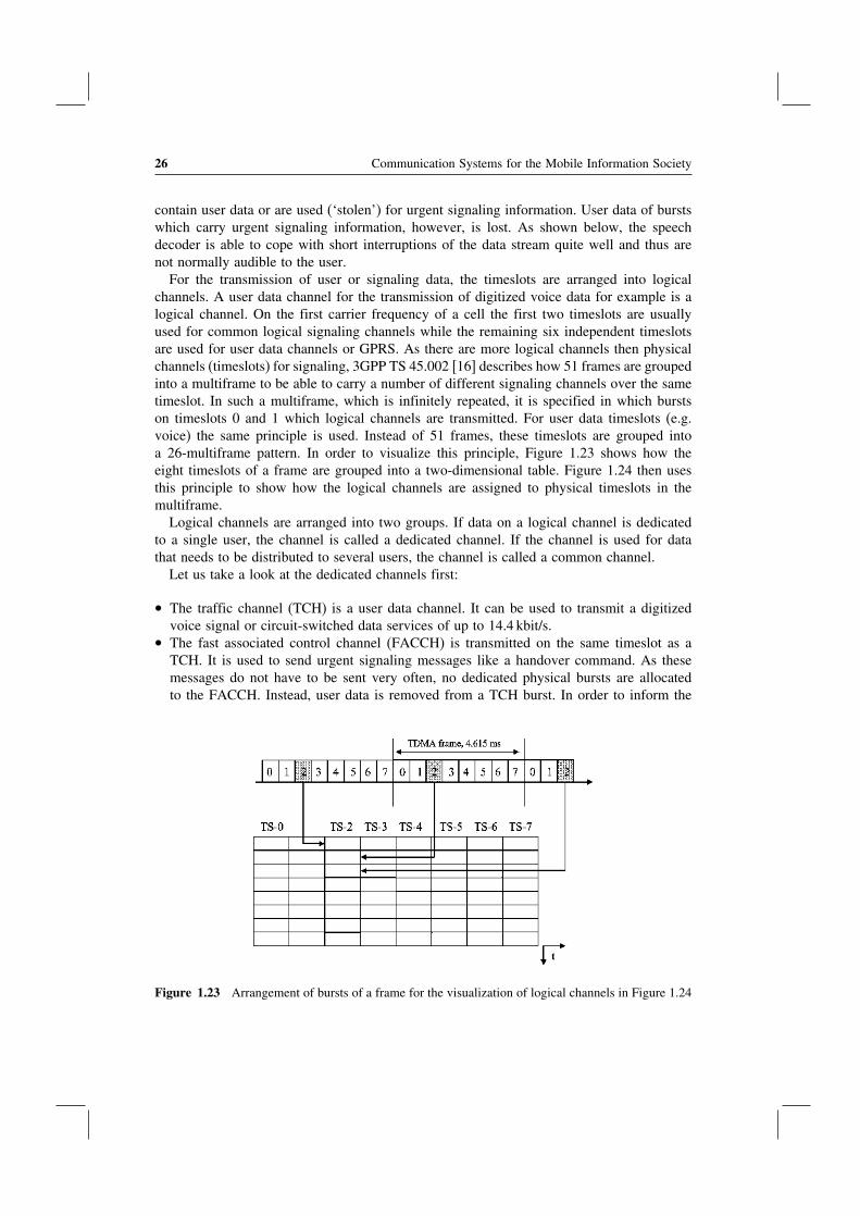
For the transmission of user or signaling data, the timeslots are arranged into logicalchannels. A user data channel for the transmission of digitized voice data for example is alogical channel. On the first carrier frequency of a cell the first two timeslots are usuallyused for common logical signaling channels while the remaining six independent timeslotsare used for user data channels or GPRS. As there are more logical channels then physicalchannels (timeslots) for signaling, 3GPP TS 45.002 [16] describes how 51 frames are groupedinto a multiframe to be able to carry a number of different signaling channels over the sametimeslot. In such a multiframe, which is infinitely repeated, it is specified in which burstson timeslots 0 and 1 which logical channels are transmitted. For user data timeslots (e.g.voice) the same principle is used. Instead of 51 frames, these timeslots are grouped intoa 26-multiframe pattern. In order to visualize this principle, Figure 1.23 shows how theeight timeslots of a frame are grouped into a two-dimensional table. Figure 1.24 then usesthis principle to show how the logical channels are assigned to physical timeslots in themultiframe.
Logical channels are arranged into two groups. If data on a logical channel is dedicatedto a single user, the channel is called a dedicated channel. If the channel is used for datathat needs to be distributed to several users, the channel is called a common channel.
Let us take a look at the dedicated channels first:
• The traffic channel (TCH) is a user data channel. It can be used to transmit a digitizedvoice signal or circuit-switched data services of up to 14.4 kbit/s.
• The fast associated control channel (FACCH) is transmitted on the same timeslot as aTCH. It is used to send urgent signaling messages like a handover command. As thesemessages do not have to be sent very often, no dedicated physical bursts are allocatedto the FACCH. Instead, user data is removed from a TCH burst. In order to inform the
Figure 1.23 Arrangement of bursts of a frame for the visualization of logical channels in Figure 1.24

Global System for Mobile Communications (GSM) 27
FN TS-0 TS-1 FN TS-2 � � � TS-7
0 FCCH SDCCH/0 0 TCH TCH
1 SCH SDCCH/0 1 TCH TCH
2 BCCH SDCCH/0 2 TCH TCH3 BCCH SDCCH/0 3 TCH TCH
4 BCCH SDCCH/1 4 TCH TCH5 BCCH SDCCH/1 5 TCH TCH
6 AGCH/PCH SDCCH/1 6 TCH TCH7 AGCH/PCH SDCCH/1 7 TCH TCH
8 AGCH/PCH SDCCH/2 8 TCH TCH9 AGCH/PCH SDCCH/2 9 TCH TCH
10 FCCH SDCCH/2 10 TCH TCH
11 SCH SDCCH/2 11 TCH TCH
12 AGCH/PCH SDCCH/3 12 SACCH SACCH
13 AGCH/PCH SDCCH/3 13 TCH TCH14 AGCH/PCH SDCCH/3 14 TCH TCH15 AGCH/PCH SDCCH/3 15 TCH TCH
16 AGCH/PCH SDCCH/4 16 TCH TCH17 AGCH/PCH SDCCH/4 17 TCH TCH18 AGCH/PCH SDCCH/4 18 TCH TCH19 AGCH/PCH SDCCH/4 19 TCH TCH
20 FCCH SDCCH/5 20 TCH TCH21 SCH SDCCH/5 21 TCH TCH22 SDCCH/0 SDCCH/5 22 TCH TCH23 SDCCH/0 SDCCH/5 23 TCH TCH24 SDCCH/0 SDCCH/6 24 TCH TCH
25 SDCCH/0 SDCCH/6 25 free free
26 SDCCH/1 SDCCH/6 0 TCH TCH27 SDCCH/1 SDCCH/6 1 TCH TCH
28 SDCCH/1 SDCCH/7 2 TCH TCH29 SDCCH/1 SDCCH/7 3 TCH TCH30 FCCH SDCCH/7 4 TCH TCH
31 SCH SDCCH/7 5 TCH TCH
32 SDCCH/2 SACCH/0 6 TCH TCH33 SDCCH/2 SACCH/0 7 TCH TCH34 SDCCH/2 SACCH/0 8 TCH TCH35 SDCCH/2 SACCH/0 9 TCH TCH
36 SDCCH/3 SACCH/1 10 TCH TCH37 SDCCH/3 SACCH/1 11 TCH TCH
38 SDCCH/3 SACCH/1 12 SACCH SACCH39 SDCCH/3 SACCH/1 13 TCH TCH40 FCCH SACCH/2 14 TCH TCH41 SCH SACCH/2 15 TCH TCH
42 SACCH/0 SACCH/2 16 TCH TCH43 SACCH/0 SACCH/2 17 TCH TCH44 SACCH/0 SACCH/3 18 TCH TCH45 SACCH/0 SACCH/3 19 TCH TCH46 SACCH/1 SACCH/3 20 TCH TCH47 SACCH/1 SACCH/3 21 TCH TCH
48 SACCH/1 free 22 TCH TCH49 SACCH/1 free 23 TCH TCH
50 free free 24 TCH TCH
25 free free
Figure 1.24 Use of timeslots in downlink direction as per 3GPP TS 45.002 [16]

28 Communication Systems for the Mobile Information Society
mobile station, the stealing bits to the left and right of the training sequence, as shown inFigure 1.22, are used. This is the reason why the FACCH is not shown in Figure 1.24.
• The slow associated control channel (SACCH) is also assigned to a dedicated connection.It is used in the uplink direction to report signal quality measurements of the serving celland neighboring cells to the network. The network then uses these values for handoverdecisions and power control. In the downlink direction, the SACCH is used to send powercontrol commands to the mobile station. Furthermore, the SACCH is used for timingadvance control which is described in Section 1.7.4 and Figure 1.29. As these messagesare only of low priority and the necessary bandwidth is very small, only a few bursts areused on a 26 multiframe at fixed intervals.
• The standalone dedicated control channel (SDCCH) is a pure signaling channel whichis used during call establishment when a subscriber has not yet been assigned a trafficchannel. Furthermore, the channel is used for signaling which is not related to callestablishment such as for the location update procedure or for sending or receiving a textmessage (SMS).
Besides the dedicated channels, which are always assigned to a single user, there are anumber of common channels that are monitored by all subscribers in a cell:
• The synchronization channel (SCH) is used by mobile stations during network and cellsearches.
• The frequency correction channel (FCCH) is used by the mobile stations to calibrate theirtransceiver units und is also used to detect the beginning of a multiframe.
• The broadcast common control channel (BCCH) is the main information channel of acell and broadcasts SYS_INFO messages that contain a variety of information about thenetwork. The channel is monitored by all mobile stations, which are switched on butcurrently not engaged in a call or signaling connection (idle mode), and broadcasts amongmany other things the following information:
– the MCC and MNC of the cell;– the identification of the cell which consists of the location area code (LAC) and the
cell ID;– to simplify the search for neighboring cells for a mobile station, the BCCH also contains
information about the frequencies used by neighboring cells. Thus, the mobile stationdoes not have to search the complete frequency band for neighboring cells.
• The paging channel (PCH) is used to inform idle subscribers of incoming calls or SMSmessages. As the network is only aware of the location area the subscriber is roamingin, the paging message is broadcast in all cells belonging to the location area. The mostimportant information element of the message is the IMSI of the subscriber or a temporaryidentification called the temporary mobile subscriber identity (TMSI). A TMSI is assignedto a mobile station during the network attach procedure and can be changed by the networkevery time the mobile station contacts the network once encryption has been activated.Thus, the subscriber has to be identified with the IMSI only once and is then addressedwith a constantly changing temporary number when encryption is not yet activated forthe communication. This increases anonymity in the network and prevents eavesdroppersfrom creating movement profiles of subscribers.
Global System for Mobile Communications (GSM) 29
• The random access channel (RACH) is the only common channel in the uplink direction.If the mobile station receives a message via the PCH that the network is requesting aconnection establishment or if the user wants to establish a call or send an SMS, theRACH is used for the initial communication with the network. This is done by sendinga channel request message. Requesting a channel has to be done via a ‘random’ channelbecause subscribers in a cell are not synchronized with each other. Thus, it cannot beensured that two devices do not try to establish a connection at the same time. Only oncea dedicated channel (SDCCH) has been assigned to the mobile station by the network canthere no longer be any collision between different subscribers of a cell. If a collision occursduring the first network access, the colliding messages are lost and the mobile stations donot receive an answer from the network. Thus, they have to repeat their channel requestmessages after expiry of a timer which is set to an initial random value. This way, it isnot very likely that the mobile stations will interfere with each other again during theirnext connection establishment attempts because they are performed at different times.
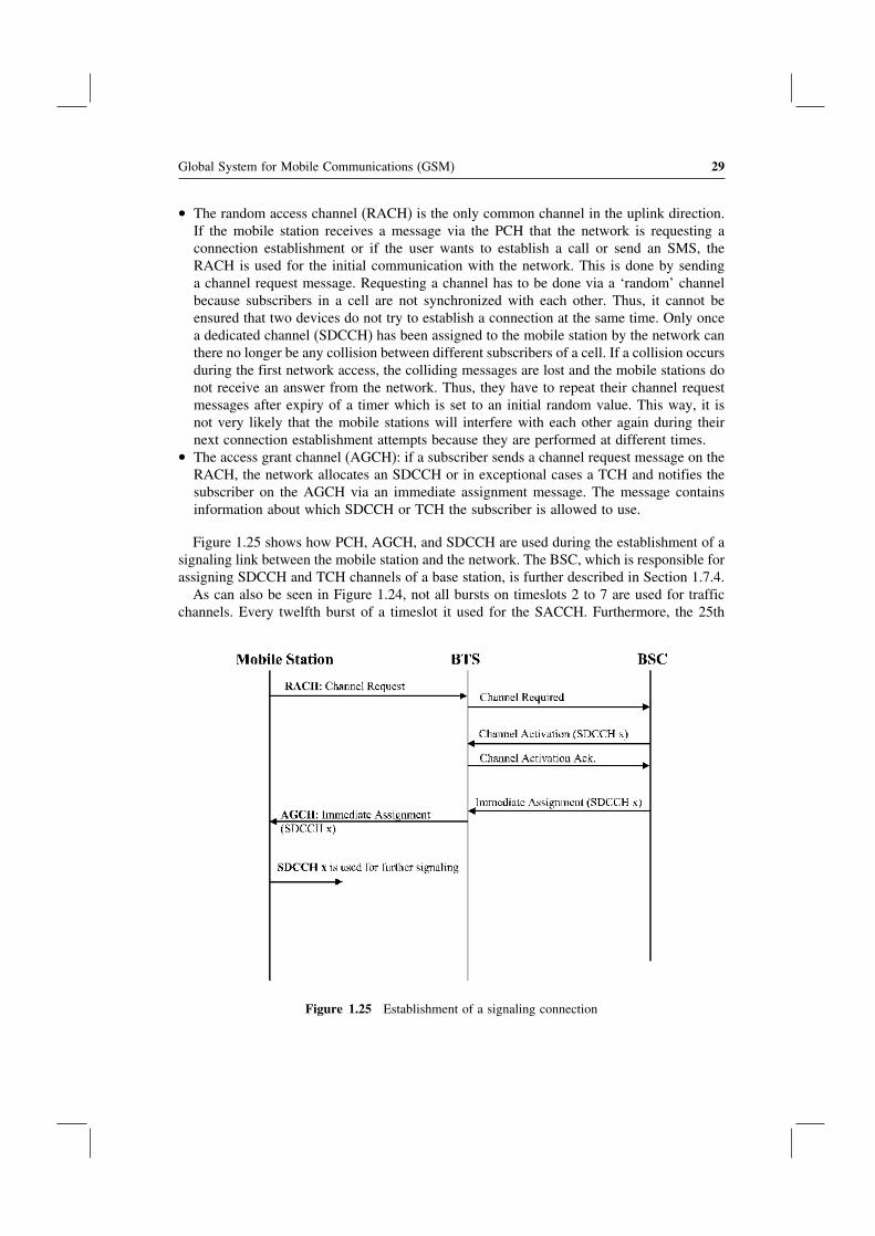
• The access grant channel (AGCH): if a subscriber sends a channel request message on theRACH, the network allocates an SDCCH or in exceptional cases a TCH and notifies thesubscriber on the AGCH via an immediate assignment message. The message containsinformation about which SDCCH or TCH the subscriber is allowed to use.
Figure 1.25 shows how PCH, AGCH, and SDCCH are used during the establishment of asignaling link between the mobile station and the network. The BSC, which is responsible forassigning SDCCH and TCH channels of a base station, is further described in Section 1.7.4.
As can also be seen in Figure 1.24, not all bursts on timeslots 2 to 7 are used for trafficchannels. Every twelfth burst of a timeslot it used for the SACCH. Furthermore, the 25th
Figure 1.25 Establishment of a signaling connection

30 Communication Systems for the Mobile Information Society
burst is also not used for carrying user data. This gap is used to enable the mobile stationto perform signal strength measurements of neighboring cells on other frequencies. This isnecessary so that the network can redirect the connection into a different cell (handover) tomaintain the call while the user is moving.
The GSM standard offers two possibilities to use the available frequencies. The simplestcase, which has been described so far, is the use of a constant carrier frequency (ARFCN) foreach channel. In order to improve the transmission quality it is also possible to use alternatingfrequencies for a single channel of a cell. This concept is known as frequency hoppingand changes the carrier frequency for every burst during a transmission. This increases theprobability that only few bits are lost if one carrier frequency experiences a lot of interferencefrom other sources like neighboring cells. In the worst case only a single burst is affectedbecause the next burst is already sent on a different frequency. Up to 64 different frequenciescan be used per base station for frequency hopping. In order to inform the mobile of theuse of frequency hopping, the immediate assignment message used during the establishmentof a signaling link contains all the information about which frequencies are used and whichhopping pattern is applied to the connection.
For carriers that transport the SCH, FCCH, and BCCH channels, frequency hopping mustnot be used. This restriction is necessary because it would be very difficult for mobilestations to find neighboring cells.
In practice, network operators use static frequencies as well as frequency hopping in theirnetworks.
The interface which connects the base station to the network and which is used to carrythe information for all logical channels is called the A-bis interface. An E-1 connection isusually used for the A-bis interface and due to its 64 kbit/s timeslot architecture the logicalchannels are transmitted in a different way than on the air interface. All common channelsas well as the information sent and received on the SDCCH and SACCH channels are sentover one or more common 64 kbit/s E-1 timeslots. This is possible because these channelsare only used for signaling data which is not time critical. On the A-bis interface thesesignaling messages are sent by using the link access protocol (LAPD). This protocol wasinitially designed for the ISDN D-channel of fixed-line networks and has been reused forGSM with only minor modifications.
For traffic channels that use a bandwidth of 13 kbit/s on the A-bis interface, only one-quarter of an E-1 timeslot is used. This means that all eight timeslots of an air interface framecan be carried on only two timeslots of the E-1 interface. A base station composed of threesectors which uses two carriers each thus requires 12 timeslots on the A-bis interface plus anadditional timeslot for the LAPD signaling. The remaining timeslots of the E-1 connectioncan be used for the communication between the network and other base stations. For thispurpose, several cells are usually daisy chained via a single E-1 connection. See Figure 1.26.
1.7.4 The Base Station Controller (BSC)
While the base station is the interface element that connects the mobile stations with thenetwork, the base station controller (BSC) is responsible for the establishment, release, andmaintenance of all connections of cells which are connected to it.
If a subscriber wants to establish a voice call, send an SMS, etc., the mobile station sendsa channel request message to the BSC as shown in Figure 1.25. The BSC then checks if
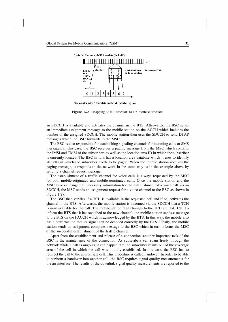
Global System for Mobile Communications (GSM) 31
Figure 1.26 Mapping of E-1 timeslots to air interface timeslots
an SDCCH is available and activates the channel in the BTS. Afterwards, the BSC sendsan immediate assignment message to the mobile station on the AGCH which includes thenumber of the assigned SDCCH. The mobile station then uses the SDCCH to send DTAPmessages which the BSC forwards to the MSC.
The BSC is also responsible for establishing signaling channels for incoming calls or SMSmessages. In this case, the BSC receives a paging message from the MSC which containsthe IMSI and TMSI of the subscriber, as well as the location area ID in which the subscriberis currently located. The BSC in turn has a location area database which it uses to identifyall cells in which the subscriber needs to be paged. When the mobile station receives thepaging message, it responds to the network in the same way as in the example above bysending a channel request message.
The establishment of a traffic channel for voice calls is always requested by the MSCfor both mobile-originated and mobile-terminated calls. Once the mobile station and theMSC have exchanged all necessary information for the establishment of a voice call via anSDCCH, the MSC sends an assignment request for a voice channel to the BSC as shown inFigure 1.27.
The BSC then verifies if a TCH is available in the requested cell and if so, activates thechannel in the BTS. Afterwards, the mobile station is informed via the SDCCH that a TCHis now available for the call. The mobile station then changes to the TCH and FACCH. Toinform the BTS that it has switched to the new channel, the mobile station sends a messageto the BTS on the FACCH which is acknowledged by the BTS. In this way, the mobile alsohas a confirmation that its signal can be decoded correctly by the BTS. Finally, the mobilestation sends an assignment complete message to the BSC which in turn informs the MSCof the successful establishment of the traffic channel.
Apart from the establishment and release of a connection, another important task of theBSC is the maintenance of the connection. As subscribers can roam freely through thenetwork while a call is ongoing it can happen that the subscriber roams out of the coveragearea of the cell in which the call was initially established. In this case, the BSC has toredirect the call to the appropriate cell. This procedure is called handover. In order to be ableto perform a handover into another cell, the BSC requires signal quality measurements forthe air interface. The results of the downlink signal quality measurements are reported to the

32 Communication Systems for the Mobile Information Society
Figure 1.27 Establishment of a traffic channel (TCH)
BSC by the mobile station, which continuously performs signal quality measurements whichit reports via the SACCH to the network. The uplink signal quality is constantly measuredby the BTS and also reported to the BSC. Apart from the signal quality of the user’s currentcell, it is also important that the mobile station reports the quality of signals it receives fromother cells. To enable the mobile station to perform these measurements, the network sendsthe frequencies of neighbouring cells via the SACCH during an ongoing call. The mobilestation then uses this information to perform the neighbouring cell measurements while thenetwork communicates with other subscribers and reports the result via measurement reportmessages in the uplink SACCH.
The network receives these measurement values and is thus able to periodically evaluateif a handover of an ongoing call to a different cell is necessary. Once the BSC decides toperform a handover, a TCH is activated in the new cell as shown in Figure 1.28. Afterwards,the BSC informs the mobile station via the old cell with a handover command message that issent over the FACCH. Important information elements of the message are the new frequencyand timeslot number of the new TCH. The mobile station then changes its transmit andreceive frequency, synchronizes to the new cell if necessary, and sends a handover accessmessage in four consecutive bursts. In the fifth burst, an SABM message is sent which isacknowledged by the BTS to signal to the mobile station that the signal can be received. Atthe same time, the BTS informs the BSC of the successful reception of the mobile station’ssignal with an establish indication message. The BSC then immediately redirects the speechpath into the new cell.
From the mobile’s point of view the handover is now finished. The BSC, however, hasto release the TCH in the old cell and has to inform the MSC of the performed handover

Global System for Mobile Communications (GSM) 33
Figure 1.28 Message flow during a handover procedure
before the handover is finished from the network’s point of view. The message to the MSCis only informative and has no impact on the continuation of the call.
In order to reduce interference, the BSC is also in charge of controlling the transmissionpower for every air interface connection. For the mobile station an active power controlhas the advantage that the transmission power can be reduced under favorable receptionconditions. The control of the mobile station’s transmission power is done using the signalquality measurements of the BTS for the connection. If the mobile station’s transmissionpower has to be increased or decreased, the BSC sends a power control message to theBTS. The BTS in turn forwards the message to the mobile station and repeats the messageon the SACCH in every frame. In practice, it can be observed that power control andadaptation is performed every one to two seconds. During call establishment, the mobilestation always uses the highest allowed power output level which is then reduced or increasedagain by the network step by step. Table 1.6 gives an overview of the mobile station powerclasses. A distinction is made for the 900 MHz versus the 1800 MHz band. While mobilestations operating on the 900 MHz band are allowed to use up to 2 watts, connections onthe 1800 MHz band are limited to 1 watt. For stationary devices or car phones with externalantennas, power values for up to 8 watts are allowed. The power values in the table representthe power output when the transmitter is active in the assigned timeslot. As the mobilestation only sends on one of the eight timeslots of a frame, the average power output of themobile station is only one-eighth of this value. The average power output of a mobile stationwhich sends with a power output of 2 watts is thus only 250 milliwatts.
The BSC is also able to control the power output of the base station. This is done byevaluating the signal measurements of the mobile stations in the current cell. It is important tonote that power control can only be performed for downlink carriers which do not broadcastthe common channels like FCH, SCH, and BCCH of a cell. On such carriers the poweroutput has to be constant in order to allow mobile stations, which are currently located inother cells of the network, to perform their neighbouring cell measurements. This would not

34 Communication Systems for the Mobile Information Society
Table 1.6 GSM power levels and corresponding power output
GSM 900Power level
GSM 900Power output
GSM 1800Power level
GSM 1800Power output
(0–2) (8 W)5 2 W 0 1 W6 1.26 W 1 631 mW7 794 mW 2 398 mW8 501 mW 3 251 mW9 316 mW 4 158 mW10 200 mW 5 100 mW11 126 mW 6 63 mW12 79 mW 7 40 mW13 50 mW 8 25 mW14 32 mW 9 16 mW15 20 mW 10 10 mW16 13 mW 11 6.3 mW17 8 mW 12 4 mW18 5 mW 13 2.5 mW19 3.2 mW 14 1.6 mW
15 1.0 mW
be possible if the signal amplitude would varies over time as the mobile stations can onlylisten to the carrier signal of neighbouring cells for a short time.
Due to the limited speed of radio waves, a time shift of the arrival of the signal can beobserved when a subscriber moves away from a base station during an ongoing call. If nocountermeasures are taken, this would mean that at some point the signal of a subscriberwould overlap with the next timeslot despite the guard time of each burst which is shown inFigure 1.22. Thus, the signal of each subscriber has to be carefully monitored and the timingof the transmission of the subscriber has to be adapted. This procedure is called timingadvance control (Figure 1.29).
The timing advance can be controlled in 64 steps (0 to 63) of 550 m. The maximumdistance between a base station and a mobile subscriber is in theory 64×550 m = 35�2 km.In practice, such a distance is not reached very often as base stations usually cover a muchsmaller area due to capacity reasons. Furthermore, the transmission power of the terminal isalso not sufficient to bridge such a distance under non-line-of-sight conditions to the base
Figure 1.29 Time shift of bursts of distant subscribers without timing advance control

Global System for Mobile Communications (GSM) 35
station. Therefore, one of the few scenarios where such a distance has to be overcome is incostal areas from ships at sea.
The control of the timing advance already starts with the first network access on the RACHwith a channel request message. This message is encoded into a very short burst that can onlytransport a few bits in exchange for large guard periods at the beginning and end of the burst.This is necessary because the mobile phone is unaware of the distance between itself andthe base station when it attempts to contact the network. Thus, the mobile station is unableto select an appropriate timing advance value. When the base station receives the burst itmeasures the delay and forwards the request including a timing advance value required forthis mobile station to the BSC. As has been shown in Figure 1.25, the BSC reacts to theconnection request by returning an immediate assignment message to the mobile station onthe AGCH. Apart from the number of the assigned SDCCH, the message also contains a firsttiming advance value to be used for the subsequent communication on the SDCCH. Oncethe connection has been successfully established, the BTS continually monitors the delayexperienced for this channel and reports any changes to the BSC. The BSC in turn instructsthe mobile station to change its timing advance by sending a message on the SACCH.
For special applications, like coastal communication, the GSM standard offers an additionaltimeslot configuration in order to increase the maximum distance to the base station to upto 120 km. This is achieved by only using every second timeslot per carrier which allows aburst to overlap into the following (empty) timeslot. While this dramatically increases therange of a cell, the number of available communication channels is cut in half. Another issueis that mobile phones that are limited to a transmission power of 1 watt (1800 MHz band) or2 watts (900 MHz band) may be able to receive the BCCH of such a cell at a great distancebut are unable to communicate with the cell in the uplink. Thus, such an extended rangeconfiguration mostly makes sense with permanently installed mobile phones with externalantennas that can transmit with a power level of up to 8 watts.
1.7.5 The TRAU for Voice Data Transmission
For the transmission of voice data, a TCH is used in GSM as described in Section 1.7.3.A TCH uses all but two bursts of a 26-burst multiframe with one being reserved for theSACCH as shown in Figure 1.24, and one which remains empty to allow the mobile stationto perform neighbouring cell measurements. As has been shown in the preceding section, aburst which is sent to or from the mobile every 4.615 ms can carry exactly 114 bits of userdata. When taking the two bursts into account, which are not used for user data of a 26-burstmultiframe, this results in a raw data rate of 22.8 kbit/s. As will be shown in the remainderof this section, a substantial part of the bandwidth of a burst is required for error detectionand correction bits. The resulting data rate for the actual user data is thus around 13 kbit/s.
The narrow bandwidth of a TCH stands in contrast to how a voice signal is transportedin the core network. Here, the PCM algorithm is used (see Section 1.6.1) to digitize thevoice signal, which makes full use of the available 64 kbit/s bandwidth of an E-1 timeslot toencode the voice signal. See Figure 1.30
A simple solution for the air interface would have been to define air interface channelsthat can also carry 64 kbit/s PCM-coded voice channels. This has not been done because thescarce resources on the air interface have to be used as efficiently as possible. The decisionto compress the speech signal was taken during the first standardization phase in the 1980s
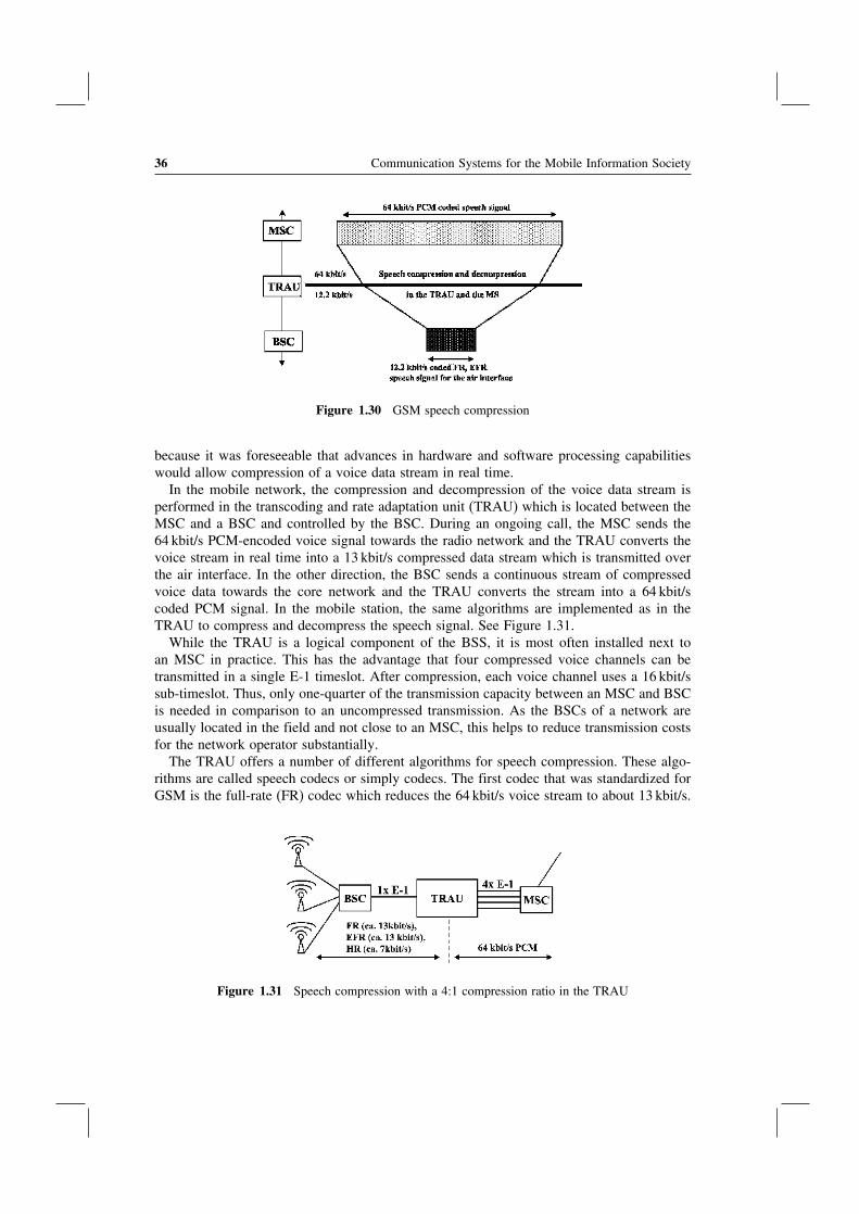
36 Communication Systems for the Mobile Information Society
Figure 1.30 GSM speech compression
because it was foreseeable that advances in hardware and software processing capabilitieswould allow compression of a voice data stream in real time.
In the mobile network, the compression and decompression of the voice data stream isperformed in the transcoding and rate adaptation unit (TRAU) which is located between theMSC and a BSC and controlled by the BSC. During an ongoing call, the MSC sends the64 kbit/s PCM-encoded voice signal towards the radio network and the TRAU converts thevoice stream in real time into a 13 kbit/s compressed data stream which is transmitted overthe air interface. In the other direction, the BSC sends a continuous stream of compressedvoice data towards the core network and the TRAU converts the stream into a 64 kbit/scoded PCM signal. In the mobile station, the same algorithms are implemented as in theTRAU to compress and decompress the speech signal. See Figure 1.31.
While the TRAU is a logical component of the BSS, it is most often installed next toan MSC in practice. This has the advantage that four compressed voice channels can betransmitted in a single E-1 timeslot. After compression, each voice channel uses a 16 kbit/ssub-timeslot. Thus, only one-quarter of the transmission capacity between an MSC and BSCis needed in comparison to an uncompressed transmission. As the BSCs of a network areusually located in the field and not close to an MSC, this helps to reduce transmission costsfor the network operator substantially.
The TRAU offers a number of different algorithms for speech compression. These algo-rithms are called speech codecs or simply codecs. The first codec that was standardized forGSM is the full-rate (FR) codec which reduces the 64 kbit/s voice stream to about 13 kbit/s.
Figure 1.31 Speech compression with a 4:1 compression ratio in the TRAU
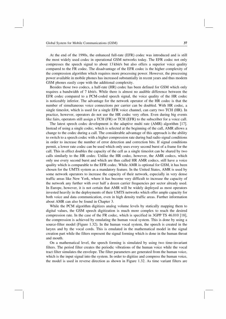
Global System for Mobile Communications (GSM) 37
At the end of the 1990s, the enhanced full-rate (EFR) codec was introduced and is stillthe most widely used codec in operational GSM networks today. The EFR codec not onlycompresses the speech signal to about 13 kbit/s but also offers a superior voice qualitycompared to the FR codec. The disadvantage of the EFR codec is the higher complexity ofthe compression algorithm which requires more processing power. However, the processingpower available in mobile phones has increased substantially in recent years and thus modernGSM phones easily cope with the additional complexity.
Besides those two codecs, a half-rate (HR) codec has been defined for GSM which onlyrequires a bandwidth of 7 kbit/s. While there is almost no audible difference between theEFR codec compared to a PCM-coded speech signal, the voice quality of the HR codecis noticeably inferior. The advantage for the network operator of the HR codec is that thenumber of simultaneous voice connections per carrier can be doubled. With HR codec, asingle timeslot, which is used for a single EFR voice channel, can carry two TCH (HR). Inpractice, however, operators do not use the HR codec very often. Even during big eventslike fairs, operators still assign a TCH (FR) or TCH (EFR) to the subscriber for a voice call.
The latest speech codec development is the adaptive multi rate (AMR) algorithm [17].Instead of using a single codec, which is selected at the beginning of the call, AMR allows achange to the codec during a call. The considerable advantage of this approach is the abilityto switch to a speech codec with a higher compression rate during bad radio signal conditionsin order to increase the number of error detection and correction bits. If signal conditionspermit, a lower rate codec can be used which only uses every second burst of a frame for thecall. This in effect doubles the capacity of the cell as a single timeslot can be shared by twocalls similarly to the HR codec. Unlike the HR codec, however, the AMR codecs, whichonly use every second burst and which are thus called HR AMR codecs, still have a voicequality which is comparable to the EFR codec. While AMR is optional for GSM, it has beenchosen for the UMTS system as a mandatory feature. In the United States, AMR is used bysome network operators to increase the capacity of their network, especially in very densetraffic areas like New York, where it has become very difficult to increase the capacity ofthe network any further with over half a dozen carrier frequencies per sector already used.In Europe, however, it is not certain that AMR will be widely deployed as most operatorsinvested heavily in the deployments of their UMTS networks which offer ample capacity forboth voice and data communication, even in high density traffic areas. Further informationabout AMR can also be found in Chapter 3.
While the PCM algorithm digitizes analog volume levels by statically mapping them todigital values, the GSM speech digitization is much more complex to reach the desiredcompression rate. In the case of the FR codec, which is specified in 3GPP TS 46.010 [18],the compression is achieved by emulating the human vocal system. This is done by using asource-filter model (Figure 1.32). In the human vocal system, the speech is created in thelarynx and by the vocal cords. This is emulated in the mathematical model in the signalcreation part while the filters represent the signal forming which is done in the human throatand mouth.
On a mathematical level, the speech forming is simulated by using two time-invariantfilters. The period filter creates the periodic vibrations of the human voice while the vocaltract filter simulates the envelope. The filter parameters are generated from the human voice,which is the input signal into the system. In order to digitize and compress the human voice,the model is used in reverse direction as shown in Figure 1.32. As time variant filters are

38 Communication Systems for the Mobile Information Society
Figure 1.32 Source-filter model of the GSM FR codec
hard to model, the system is simplified by generating a pair of filter parameters for aninterval of 20 milliseconds. As an input to the algorithm, a speech signal is used that haspreviously been converted into an 8- or 13-bit PCM codec. As the PCM algorithm delivers8000 values per second, the FR codec requires 160 values for a 20 ms interval to calculatethe filter parameters. As eight bits are used per value, 8 bits × 160 values = 1280 inputbits are used per 20 ms interval. For the period filter, the input bits are used to generate afilter parameter with a length of 36 bits. Afterwards, the filter is applied to the original inputsignal. The resulting signal is then used to calculate another filter parameter with a length of36 bits for the vocal tract filter. Afterwards, the signal is again sent through the vocal tractfilter with the filter parameter applied. The signal, which is thus created, is called the ‘restsignal’ and coded into 188 bits. See Figure 1.33.
Voice,PCM coded20 ms,160 values,1280 bits
Determination offilter parametersfor the vocaltract filter
signal forming
36 Bit
Determination offilter parametersfor the period filter
36 Bit
Coding of the ‘restsignal’
188 Bit
Frame (260 bits) for transmission every 20 milliseconds
Voice,PCM coded 20 ms, 160 values,1280 bits
Vocal tractfilter
signal forming
Period filterExcitationsignal
Sender
Receiver
Figure 1.33 Complete transmission chain with transmitter and receiver of the GSM FR codec

Global System for Mobile Communications (GSM) 39
Once all parameters have been calculated, the two 36-bit filter parameters and the restsignal, which is coded into 188 bits, are sent to the receiver. Thus, the original information,which was coded in 1280 bits, has been reduced to 260 bits. In the receiver, the filterprocedure is applied in reverse order on the rest signal and thus the original signal isrecreated. As the procedure uses a lossy compression algorithm, the original signal and therecreated signal at the other end are no longer exactly identical. For the human ear, however,the differences are almost inaudible.
Before a 260-bit data frame is transmitted over the air interface every 20 ms, it traverses anumber of additional functional blocks which are not implemented in the TRAU but in thebase station. These additional functional blocks are shown in Figure 1.34.
In a first step, the voice frames are processed in the channel coder unit, which addserror detection and correction information to the data stream. This step is very important asthe transmission over the air interface is prone to frequent transmission errors due to theconstantly changing radio environment. Furthermore, the compressed voice information isvery sensitive and even a few bits that might be changed while the frame is transmittedover the air interface create an audible distortion. In order to prevent this, the channelcoder separates the 260 bits of a voice data frame into three different classes as shown inFigure 1.35.
Fifty of the 260 bits of a speech frame are class Ia bits and extremely important for theoverall reproduction of the voice signal at the receiver side. Such bits are for example thehigher order bits of the filter parameters. In order to enable the receiver to verify the correcttransmission of those bits, a three-bit CRC checksum is calculated and added to the datastream. If the receiver later on cannot recreate the checksum with the received bits, the frameis discarded.
Another 132 bits of the frame are also quite important and are thus put into class Ib.However, no checksum is calculated for them. In order to generate the exact amount of bitsthat are necessary to fill a GSM burst, four filler bits are inserted. Afterwards, the class Ia
Figure 1.34 Transmission path in the downlink direction between network and mobile station

40 Communication Systems for the Mobile Information Society
Figure 1.35 GSM channel coder for full-rate speech frames
bits, checksum, class Ib bits, and the four filler bits are treated by a convolutional coderwhich adds redundancy to the data stream. For each input bit, the convolutional decodercalculates two output bits. For the computation of the output bits the coder uses not only thecurrent bit but also uses information about the values of the previous bits. For each inputbit, two output bits are calculated. This mathematical algorithm is also called a half-rateconvolutional coder.
The remaining 78 bits of the original 260-bit data frame belong to the third class whichis called class II. These are not protected by a checksum and no redundancy is added forthem. Errors which occur during the transmission of these bits can neither be detected norcorrected.
As has been shown, the channel coder uses the 260-bit input frame to generate 456 bitson the output side. As a burst on the air interface can carry exactly 114 bits, four burstsare necessary to carry the frame. As the bursts of a traffic channel are transmitted every4.6152 ms, the time it takes to transmit the frame over the air interface is about 20 ms. Inorder to get to exactly 20 ms, the empty burst and the burst used for the SACCH per 26-burstmultiframe has to be included in the calculation.
Due to the redundancy added by the channel coder, it is possible to correct a high numberof faulty bits per frame. The convolutional decoder, however, has one weak point: if severalconsecutive bits are changed during the transmission over the air interface, the convolutionaldecoder on the receiver side is not able to correctly reconstruct the original frame. Thiseffect is often observed as air interface disturbances usually affect several bits in a row.
In order to decrease this effect, the interleaver changes the bit order of a 456-bit data framein a specified pattern over eight bursts (Figure 1.36). Consecutive frames are thus interlockedwith each other. On the receiver side, the frames are put through the de-interleaver, whichputs the bits again into the correct order. If several consecutive bits are changed due toair interface signal distortion, this operation disperses the faulty bits in the frame and theconvolutional decoder can thus correctly restore the original bits. A disadvantage of theinterleaver, however, is an increased delay of the voice signal. In addition to the delay of20 ms generated by the full-rate coder, the interleaver adds another 40 ms as a speech frame isspread over eight bursts instead of being transmitted consecutively in four bursts. Compared

Global System for Mobile Communications (GSM) 41
Figure 1.36 Frame interleaving
to a voice call in a fixed-line network, a mobile network thus introduces a delay of at least60 ms. If the call is established between two mobile phones, the delay is at least 120 ms asthe transmission chain is traversed twice.
The next module of the transmission chain is the cipherer (Figure 1.37), which encrypts thedata frames it receives from the interleaver. GSM uses, like most communication systems,
Figure 1.37 Ciphering of an air interface burst

42 Communication Systems for the Mobile Information Society
a stream cipher algorithm. In order to encrypt the data stream, a ciphering key (Kc) iscalculated in the authentication center and on the SIM card by using a random number(RAND) and the secret key (Ki) as input parameters for the A8 algorithm. Together with theGSM frame number, which is increased for every air interface frame, Kc is used as inputparameter for the A5 ciphering algorithm. The A5 algorithm computes a 114-bit sequencewhich is XOR combined with the bits of the original data stream. As the frame number isdifferent for every burst, it is ensured that the 114-bit ciphering sequence also changes forevery burst which further enhances security.
In order to be as flexible as possible, a number of different ciphering algorithms havebeen specified for GSM. These are called A5/1, A5/2, A5/3, and so on. Thus, it is possibleto export GSM network equipment to countries where export restrictions prevent the saleof some ciphering algorithms and technologies. Furthermore, it is possible to introduce newciphering algorithms into already existing networks in order to react to security issues if aflaw is detected in one of the currently used algorithms. The selection of the ciphering algo-rithm also depends on the capabilities of the mobile station. During the establishment of aconnection, the mobile station informs the network which ciphering algorithms it supports.The network can then choose an algorithm which is supported by the network and the terminal.
When the mobile station establishes a new connection to the network, its identity is verifiedbefore the mobile station is allowed to proceed with the call setup. This procedure has alreadybeen described in Section 1.6.4. Once the terminal and subscriber have been authenticated,it is also possible for the MSC to start encryption by sending a ciphering command tothe mobile station. The ciphering command message contains, among other informationelements, the ciphering key, Kc, which is used by the base station for the ciphering of theconnection on the air interface. Before the BSC forwards the message to the mobile station,however, the ciphering key is removed from the message because this information must notbe sent over the air interface. The mobile station, however, does not need to receive theciphering key from the network as the SIM card calculates the Kc on its own and forwardsthe key to the mobile station together with the SRES during the authentication procedure.Figure 1.40 shows how ciphering is activated during a location update procedure.
Unfortunately, there are a number of weak spots in the overall GSM encryption architec-ture. One serious problem is that encryption has only been specified as an optional feature.Thus, encryption can be easily switched on or off by the network operator. Some mobilephones like the Siemens S series for example show a ‘∗!∗’ symbol on the display if cipheringis disabled. So far, however, the author of this book has only seen this symbol in a labora-tory environment where encryption was deactivated on purpose. Thus, it can be assumed thatpublic networks, in the majority of cases, only very rarely deactivate this feature. Another weak-ness in the overall security architecture is the fact that a connection is only ciphered betweenthe BTS and the mobile station. All other interfaces between components of the network likethe connection between the base station and the BSC or the connection between the TRAUand the MSC are not protected. As many network operators use microwave links betweenbase stations and BSCs, it is possible to intercept calls with suitable microwave equipmentwithout having physical access to any component of the network.
At the end of the transmission chain, the modulator maps the digital data onto an analogcarrier, which uses a bandwidth of 200 kHz. This mapping is done by encoding the bits intochanges of the carrier frequency. As the frequency change takes a finite amount of time, amethod called Gaussian minimum shift keying (GMSK) is used, which smoothes the flanks

Global System for Mobile Communications (GSM) 43
created by the frequency changes. GMSK has been selected for GSM as its modulation anddemodulation properties are easy to handle and implement into hardware and due to the factthat it interferes only slightly with neighboring channels.
In order to reduce the interference on the air interface and to increase the operating timeof the mobile station, data bursts are only sent if a speech signal is detected. This method iscalled discontinuous transmission (DTX) and can be activated independently in the uplinkand downlink directions (Figure 1.38). Since only one person is speaking at a time duringa conversation, one of the two speech channels can usually be deactivated. In the downlinkdirection, this is managed by the voice activity detection (VAD) algorithm in the TRAUwhile in the uplink direction the VAD is implemented in the mobile station.
Simply deactivating a speech channel, however, creates a very undesirable side effect. Asno speech signal is transmitted anymore, the receiver no longer hears the background noiseof the other side. This can be very irritating especially for high-volume background noiselevels such as if a person is driving in a car or sitting in a train. Therefore, it is necessary togenerate artificial noise, called comfort noise, which simulates the background noise of theother party to the listener. As the background noise can change over time, the mobile phoneor the network respectively analyze the background noise of the channel and calculate anapproximation for the current situation. This approximation is then exchanged between themobile phone and the TRAU every 480 ms. Additional benefits for the network and mobilephone are the ability to perform periodic signal quality measurements of the channel andthe ability to use these frames to get an estimation on the current signal timing in order toadapt the timing advance for the call if necessary. How well this method performs is clearlyaudible as this procedure is used in all mobile phone calls today and the simulation of thebackground noise in most cases cannot be differentiated from the original signal.
Despite using sophisticated methods for error correction, it is still possible that parts ofa frame are destroyed beyond repair during the transmission on the air interface. In thesecases, the complete 20 ms voice frame is discarded by the receiver and the previous datablock is used instead to generate an output signal. Most errors that are repaired this wayremain undetected by the listener. This trick, however, cannot be used indefinitely. If after320 ms still no valid data block has been received, the channel is muted and the decoderkeeps trying to decode the subsequent frames. If, during the following seconds, no valid dataframe is received, the connection is terminated and the call drops.
Many of the previously mentioned procedures have specifically been developed for thetransmission of voice frames. For circuit-switched data connections, however, a number ofmodifications are necessary. While it is possible to tolerate a number of faulty bits for voiceframes or discarding frames if a CRC error is detected, this is not possible for data calls. Ifeven a single bit is faulty, a retransmission of at least a single frame has to be performed as
Figure 1.38 Discontinuous transmission (DTX)

44 Communication Systems for the Mobile Information Society
most applications cannot tolerate a faulty data stream. In order to increase the likelihood tocorrectly reconstruct the initial data stream, the interleaver spreads the bits of a frame overa much larger number of bursts than the eight bursts used for voice frames. Furthermore,the channel coder, which separates the bits of a frame into different classes based on theirimportance, had to be adapted for data calls as well, as all bits are equally important. Thus,the convolutional decoder has to be used for all bits of a frame. Finally, it is also not possibleto use a lossy data compression scheme for data calls. Therefore, the TRAU operates in atransparent mode for data calls. If the data stream can be compressed this has to be performedby higher layers or by the data application itself.
With a radio receiver or an amplifier of a stereo set, the different states of a GSMconnection can be made audible. This is possible due to the fact that the activation anddeactivation of the transmitter of the mobile station induce an audible sound in the amplifierpart of audio devices. If the GSM mobile station is held close enough to an activated radio oran amplifier during the establishment of a call, the typical noise pattern can be heard, whichis generated by the exchange of messages on the signaling channel (SDCCH). At some pointduring the signaling phase, a TCH is assigned to the mobile station at which point the noisepattern changes. As a TCH burst is transmitted every 4.615 ms, the transmitter of the mobilestation is switched on and off with a frequency of 217 Hertz. If the background noise is lowenough or the mute button of the telephone is pressed, the mobile station changes into thediscontinuous transmission mode for the uplink part of the channel. This can be heard aswell, as the constant 217 Hz hum is replaced by single short bursts every 0.5 s.
For incoming calls, this method can also be used to detect that a mobile phone startscommunicating with the network on the SDDCH already one to two seconds before it startsringing. This delay is due to the fact that the mobile station first needs to go through theauthentication phase and the activation of the ciphering for the channel. Only afterwards canthe network forward further information to the mobile station as to why the channel wasestablished. This is also the reason why it takes a much longer time for the alerting tone tobe heard when calling a mobile phone compared to calling a fixed-line phone.
Some mobile phones possess a number of interesting network monitoring functionalitieswhich are hidden in the mobile phone software and are usually not directly accessible viathe phone’s menu. These network monitors allow the visualization of many procedures andparameters that have been discussed in this chapter such as the timing advance, channelallocation, power control, the cell-id, neighboring cell information, handover, cell reselection,etc. On the Internet, various web pages can be found that explain how these monitors canbe activated, depending on the type and model of the phone. As the activation proceduresare different for every phone, it is not possible to give a general recommendation. However,by using the manufacturer and model of the phone in combination with terms like ‘GSMnetwork monitor’, ‘GSM netmonitor’ or ‘GSM monitoring mode’, it is relatively easy todiscover if and how the monitoring mode can be activated for a specific phone.
1.8 Mobility Management and Call Control
As all components of a GSM mobile network have now been introduced, the followingsection gives an overview of the three processes that allow a subscriber to roam throughoutthe network.

Global System for Mobile Communications (GSM) 45
1.8.1 Location Area and Location Area Update
As the network needs to be able to forward an incoming call, the subscriber’s location mustbe known. After the mobile phone is switched on, its first action is to register with thenetwork. Therefore the network becomes aware of the current location of the user, which canchange at any time due to the mobility of the user. If the user roams into the area of a newcell it may need to inform the network of this change. In order to reduce the signaling loadin the radio network, several cells are grouped into a location area. The network informs themobile station via the BCCH of a cell not only of the cell-ID but also of the location areathat the new cell belongs to. The mobile station thus only has to report its new location ifthe new cell belongs to a new location area. Grouping several cells into location areas notonly reduces the signaling load in the network but also reduces the power consumption ofthe mobile. A disadvantage of this method is that the network operator is only aware of thecurrent location area of the subscriber but not of the exact cell. Therefore, the network has tosearch for the mobile station in all cells of a location area for an incoming call or SMS. Thisprocedure is called paging. The size of a location area can be set by the operator dependingon his particular needs. In operational networks, usually 20 to 30 cells are grouped into alocation area (Figure 1.39).
Figure 1.40 shows how a location area update procedure is performed. After a signalingconnection has been established, the mobile station sends a location update request messageto the MSC, which is transparently forwarded by the radio network. Before the message canbe sent, however, the mobile station needs to authenticate itself first and ciphering is usuallyactivated before as well.
Once the connection is secured against eavesdropping, the mobile station is usuallyassigned a new TMSI by the network, which it will use for the next connection establishment
Figure 1.39 Cells in different location areas

46 Communication Systems for the Mobile Information Society
Figure 1.40 Message flow for a location update procedure
to identify itself instead of the IMSI. By using a constantly changing temporary ID, theidentity of a subscriber is not revealed to listeners during the first phase of the callwhich is not ciphered. Once TMSI reallocation has been performed, the location areaupdate message is sent to the network which acknowledges the correct reception. Afterreceiving the acknowledgment, the connection is terminated and the mobile station returns toidle state.
If the old and new location areas are under the administration of two different MSC/VLRs,a number of additional steps are necessary. In this case, the new MSC/VLR has to informthe HLR that the subscriber has roamed into its area of responsibility. The HLR then deletesthe record of the subscriber in the old MSC/VLR. This procedure is called an Inter-MSClocation update. From the mobile point of view, however, there is no difference to a standardlocation update as the additional messages are only exchanged in the core network.
1.8.2 The Mobile Terminated Call
An incoming call for a mobile subscriber is called a mobile terminated call by the GSMstandards. The main difference between a mobile network and a fixed-line PSTN networkis the fact that the telephone number of the subscriber does not hold any information aboutwhere the subscriber is located. In the mobile network it is thus necessary to query the HLRfor the current location of the subscriber before the call can be forwarded to the correctswitching center.

Global System for Mobile Communications (GSM) 47
Figure 1.41 Mobile terminated call establishment, part 1
Figure 1.41 shows the first part of the message flow for a mobile terminated call initiatedfrom a fixed-line subscriber. From the fixed-line network, the gateway-MSC (G-MSC)receives the telephone number (MSISDN) of the called party via an ISUP IAM message.The subsequent message flow on this interface is as shown in Figure 1.6 and the fixed-linenetwork does not have to be aware that the called party is a mobile subscriber. The G-MSC inthis example is simply a normal MSC with additional connections to other networks. Whenthe G-MSC receives the IAM message, it sends a send routing information message (SRI)to the HLR in order to locate the subscriber in the network. The MSC currently responsiblefor the subscriber is also called the subscriber’s visited MSC (V-MSC).
The HLR then determines the subscriber’s IMSI by using the MSISDN to search throughits database and thus is able to locate the subscriber’s current V-MSC. The HLR then sends aprovide roaming number (PRN) message to the V-MSC/VLR to inform the switching centerof the incoming call. In the V-MSC/VLR, the IMSI of the subscriber, which is part of thePRN message, is associated with a temporary mobile station roaming number (MSRN) whichis returned to the HLR. The HLR then transparently returns the MSRN to the Gateway-MSC.
The G-MSC uses the MSRN to forward the call to the V-MSC. This is possible as theMSRN not only temporarily identifies the subscriber in the V-MSC/VLR but also uniquelyidentifies the V-MSC to external switches. To forward the call from the G-MSC to theV-MSC, an IAM message is used again, which instead of the MSISDN contains the MSRNto identify the subscriber. This has been done as it is possible, and even likely, that there aretransit switching centers between the G-MSC and V-MSC, which are thus able to forwardthe call without querying the HLR themselves.
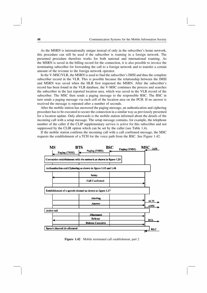
48 Communication Systems for the Mobile Information Society
As the MSRN is internationally unique instead of only in the subscriber’s home network,this procedure can still be used if the subscriber is roaming in a foreign network. Thepresented procedure therefore works for both national and international roaming. Asthe MSRN is saved in the billing record for the connection, it is also possible to invoice theterminating subscriber for forwarding the call to a foreign network and to transfer a certainamount of the revenue to the foreign network operator.
In the V-MSC/VLR, the MSRN is used to find the subscriber’s IMSI and thus the completesubscriber record in the VLR. This is possible because the relationship between the IMSIand MSRN was saved when the HLR first requested the MSRN. After the subscriber’srecord has been found in the VLR database, the V-MSC continues the process and searchesthe subscriber in the last reported location area, which was saved in the VLR record of thesubscriber. The MSC then sends a paging message to the responsible BSC. The BSC inturn sends a paging message via each cell of the location area on the PCH. If no answer isreceived the message is repeated after a number of seconds.
After the mobile station has answered the paging message, an authentication and cipheringprocedure has to be executed to secure the connection in a similar way as previously presentedfor a location update. Only afterwards is the mobile station informed about the details of theincoming call with a setup message. The setup message contains, for example, the telephonenumber of the caller if the CLIP supplementary service is active for this subscriber and notsuppressed by the CLIR option which can be set by the caller (see Table 1.4).
If the mobile station confirms the incoming call with a call confirmed message, the MSCrequests the establishment of a TCH for the voice path from the BSC. See Figure 1.42.
Figure 1.42 Mobile terminated call establishment, part 2

Global System for Mobile Communications (GSM) 49
After successful establishment of the speech path, the mobile station returns an alertingmessage and thus informs the MSC that the subscriber is informed of the incoming call (thephone starts ringing). The V-MSC then forwards this information via the address completemessage (ACM) to the G-MSC. The G-MSC then also forwards the alerting indication tothe fixed-line switch via its own ACM message.
Once the mobile subscriber accepts the call by pressing the answer button, the mobilestation returns an answer message to the V-MSC. Here, an ISUP answer (ANM) message isgenerated and returned to the G-MSC. The G-MSC forwards this information again via anANM message back to the fixed-line switching center.
While the conversation is ongoing, the network continues to exchange messages betweendifferent components in order to ensure that the connection is maintained. Most of themessages are measurement report messages, which are exchanged between the mobile station,the base station, and the BSC. If necessary, the BSC can thus trigger a handover to a differentcell. More about the handover process can be found in Section 1.8.3.
If the mobile subscriber wants to end the call, the mobile station sends a disconnectmessage to the network. After releasing the traffic channel with the mobile station and aftersending an ISUP release (REL) message to the other party, all resources in the network arefreed and the call ends.
In this example, it has been assumed that the mobile subscriber is not in the area that iscovered by the G-MSC. Such a scenario, however, is quite likely if a call is initiated bya fixed-line subscriber to a mobile subscriber which currently roams in the same region.As the fixed-line network usually forwards the call to the closest MSC to save costs, theG-MSC will in many cases also be the V-MSC for the connection. The G-MSC recognizessuch a scenario if the MSRN returned by the HLR in the SRI acknowledge message containsa number, which is from the MSRN pool of the G-MSC. In this case, the call is treatedin the G-MSC right away and the ISUP signaling inside the mobile network (IAM, ACM,ANM) is left out. More details about call establishment procedures in GSM networks can befound in [19].
1.8.3 Handover Scenarios
If reception conditions deteriorate during a call due to a change in the location of thesubscriber, the BSC has to initiate a handover procedure. The basic procedure and thenecessary messages have already been shown in Figure 1.28. Depending on which parts ofthe network are involved in the handover, one of the following handover scenarios is usedto ensure that the connection remains established:
• Intra-BSC handover: in this scenario, the current cell and new cell are connected to thesame BSC. This scenario is shown in Figure 1.28.
• Inter-BSC handover: if a handover has to be performed into a cell which is connected to asecond BSC, the current BSC is not able to control the handover itself as no direct signalingconnection exists between the BSCs of a network. Thus, the current BSC requests thatthe MSC initiates a handover to the other cell by sending a handover request message.Important parameters of the message are the cell-ID and the location area code (LAC) ofthe new cell. As the MSC administers a list of all LACs and cells under its control, it canfind the correct BSC and request the establishment of a traffic channel for the handover

50 Communication Systems for the Mobile Information Society
in a next step. Once the new BSC has prepared the speech channel (TCH) in the newcell, the MSC returns a handover command to the mobile station via the still existingconnection over the current BSC. The mobile station then performs the handover to thenew cell. Once the new cell and BSC have detected the successful handover, the MSCcan switch over the speech path and inform the old BSC that the traffic channel for thisconnection can be released.
• Inter-MSC handover: if the current and new cells for a handover procedure are notconnected to the same MSC, the handover procedure is even more complicated. As in theexample before, the BSC detects that the new cell is not in its area of responsibility andthus forwards the handover request to the MSC. The MSC also detects that the LAC ofthe new cell is not part of its coverage area. Therefore, the MSC looks into another tablewhich lists all LACs of the neighboring MSCs. As the MSC in the next step contactsa second MSC, the following terminology is introduced to unambiguously identify thetwo MSCs: the MSC which has assigned a MSRN at the beginning of the call is calledthe anchor-MSC (A-MSC) of the connection. The MSC that receives the call during ahandover is called the relay-MSC (R-MSC). See Figure 1.43.
In order to perform the handover, the A-MSC sends a MAP (mobile application part,see Section 1.4.2) handover message to the R-MSC. The R-MSC then asks the responsibleBSC to establish a traffic channel in the requested cell and reports back to the A-MSC. TheA-MSC then instructs the mobile station via the still existing connection over the current cellto perform the handover. Once the handover has been performed successfully, the R-MSCreports the successful handover to the A-MSC. The A-MSC can then switch the voice pathtowards the R-MSC. Afterwards, the resources in the old BSC and cell are released.
If the subscriber yet again changes to another cell during the call, which is controlled byyet another MSC, a subsequent inter-MSC handover has to be performed (Figure 1.44).
For this scenario, the current relay-MSC (R-MSC 1) reports to the A-MSC that a subse-quent inter-MSC handover to R-MSC 2 is required in order to maintain the call. The A-MSCthen instructs R-MSC 2 to establish a channel in the requested cell. Once the speech channel isready in the new cell, the A-MSC sends the handover command message via R-MSC 1.
Figure 1.43 Inter-MSC handover
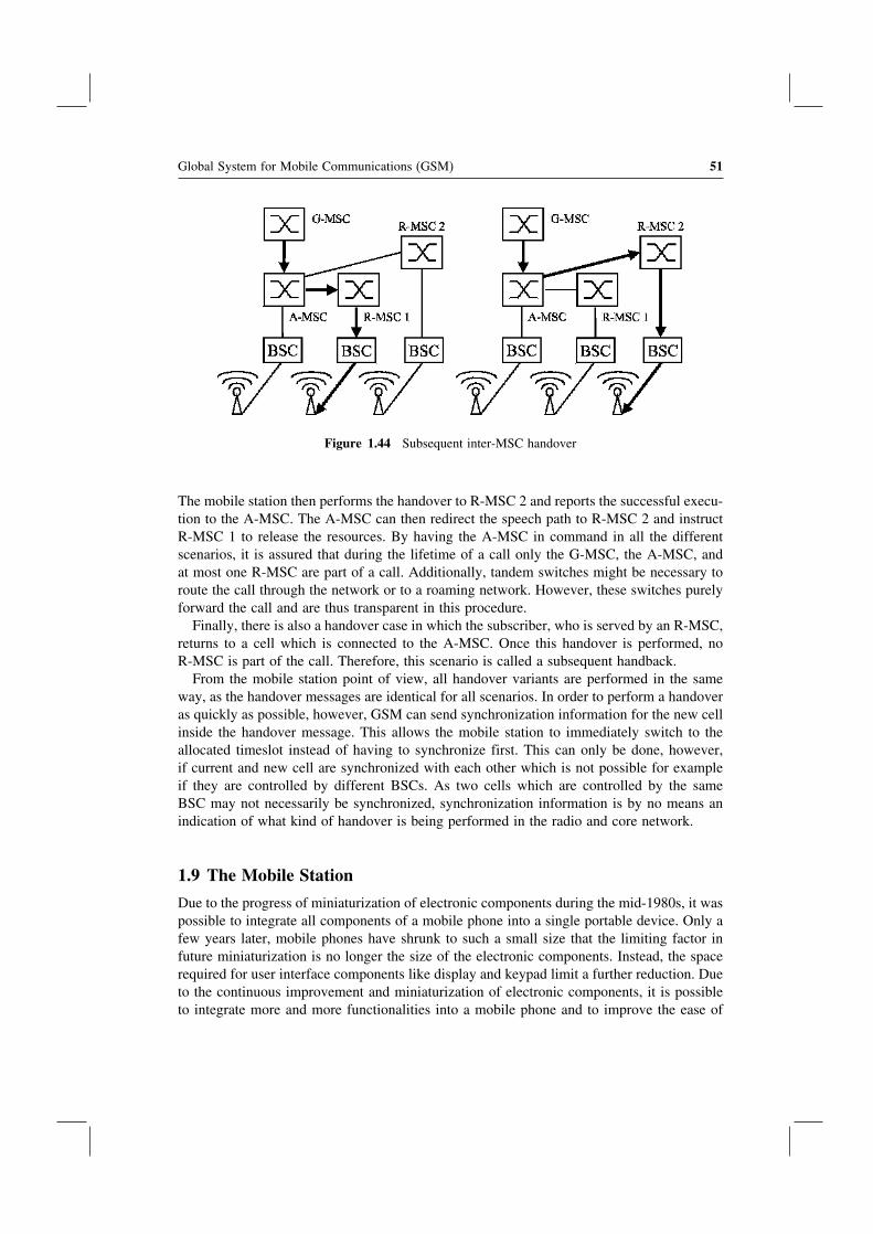
Global System for Mobile Communications (GSM) 51
Figure 1.44 Subsequent inter-MSC handover
The mobile station then performs the handover to R-MSC 2 and reports the successful execu-tion to the A-MSC. The A-MSC can then redirect the speech path to R-MSC 2 and instructR-MSC 1 to release the resources. By having the A-MSC in command in all the differentscenarios, it is assured that during the lifetime of a call only the G-MSC, the A-MSC, andat most one R-MSC are part of a call. Additionally, tandem switches might be necessary toroute the call through the network or to a roaming network. However, these switches purelyforward the call and are thus transparent in this procedure.
Finally, there is also a handover case in which the subscriber, who is served by an R-MSC,returns to a cell which is connected to the A-MSC. Once this handover is performed, noR-MSC is part of the call. Therefore, this scenario is called a subsequent handback.
From the mobile station point of view, all handover variants are performed in the sameway, as the handover messages are identical for all scenarios. In order to perform a handoveras quickly as possible, however, GSM can send synchronization information for the new cellinside the handover message. This allows the mobile station to immediately switch to theallocated timeslot instead of having to synchronize first. This can only be done, however,if current and new cell are synchronized with each other which is not possible for exampleif they are controlled by different BSCs. As two cells which are controlled by the sameBSC may not necessarily be synchronized, synchronization information is by no means anindication of what kind of handover is being performed in the radio and core network.
1.9 The Mobile Station
Due to the progress of miniaturization of electronic components during the mid-1980s, it waspossible to integrate all components of a mobile phone into a single portable device. Only afew years later, mobile phones have shrunk to such a small size that the limiting factor infuture miniaturization is no longer the size of the electronic components. Instead, the spacerequired for user interface components like display and keypad limit a further reduction. Dueto the continuous improvement and miniaturization of electronic components, it is possibleto integrate more and more functionalities into a mobile phone and to improve the ease of
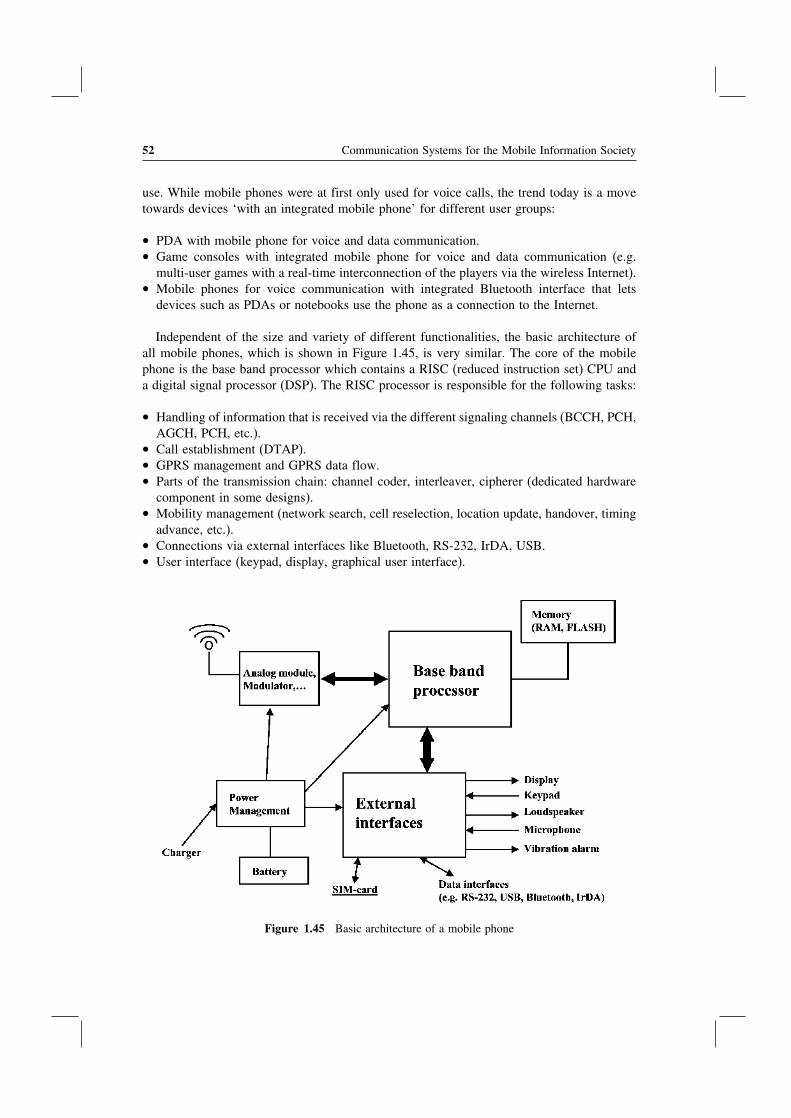
52 Communication Systems for the Mobile Information Society
use. While mobile phones were at first only used for voice calls, the trend today is a movetowards devices ‘with an integrated mobile phone’ for different user groups:
• PDA with mobile phone for voice and data communication.• Game consoles with integrated mobile phone for voice and data communication (e.g.
multi-user games with a real-time interconnection of the players via the wireless Internet).• Mobile phones for voice communication with integrated Bluetooth interface that lets
devices such as PDAs or notebooks use the phone as a connection to the Internet.
Independent of the size and variety of different functionalities, the basic architecture ofall mobile phones, which is shown in Figure 1.45, is very similar. The core of the mobilephone is the base band processor which contains a RISC (reduced instruction set) CPU anda digital signal processor (DSP). The RISC processor is responsible for the following tasks:
• Handling of information that is received via the different signaling channels (BCCH, PCH,AGCH, PCH, etc.).
• Call establishment (DTAP).• GPRS management and GPRS data flow.• Parts of the transmission chain: channel coder, interleaver, cipherer (dedicated hardware
component in some designs).• Mobility management (network search, cell reselection, location update, handover, timing
advance, etc.).• Connections via external interfaces like Bluetooth, RS-232, IrDA, USB.• User interface (keypad, display, graphical user interface).
Figure 1.45 Basic architecture of a mobile phone
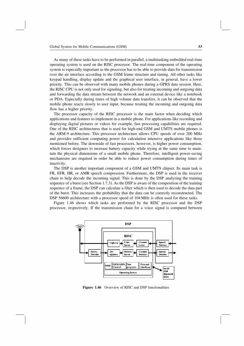
Global System for Mobile Communications (GSM) 53
As many of these tasks have to be performed in parallel, a multitasking embedded real-timeoperating system is used on the RISC processor. The real-time component of the operatingsystem is especially important as the processor has to be able to provide data for transmissionover the air interface according to the GSM frame structure and timing. All other tasks likekeypad handling, display update and the graphical user interface, in general, have a lowerpriority. This can be observed with many mobile phones during a GPRS data session. Here,the RISC CPU is not only used for signaling, but also for treating incoming and outgoing dataand forwarding the data stream between the network and an external device like a notebookor PDA. Especially during times of high volume data transfers, it can be observed that themobile phone reacts slowly to user input, because treating the incoming and outgoing dataflow has a higher priority.
The processor capacity of the RISC processor is the main factor when deciding whichapplications and features to implement in a mobile phone. For applications like recording anddisplaying digital pictures or videos for example, fast processing capabilities are required.One of the RISC architectures that is used for high-end GSM and UMTS mobile phones isthe ARM-9 architecture. This processor architecture allows CPU speeds of over 200 MHzand provides sufficient computing power for calculation intensive applications like thosementioned before. The downside of fast processors, however, is higher power consumption,which forces designers to increase battery capacity while trying at the same time to main-tain the physical dimensions of a small mobile phone. Therefore, intelligent power-savingmechanisms are required in order be able to reduce power consumption during times ofinactivity.
The DSP is another important component of a GSM and UMTS chipset. Its main task isFR, EFR, HR, or AMR speech compression. Furthermore, the DSP is used in the receiverchain to help decode the incoming signal. This is done by the DSP analyzing the trainingsequence of a burst (see Section 1.7.3). As the DSP is aware of the composition of the trainingsequence of a frame, the DSP can calculate a filter which is then used to decode the data partof the burst. This increases the probability that the data can be correctly reconstructed. TheDSP 56600 architecture with a processor speed of 104 MHz is often used for these tasks.
Figure 1.46 shows which tasks are performed by the RISC processor and the DSPprocessor, respectively. If the transmission chain for a voice signal is compared between
Figure 1.46 Overview of RISC and DSP functionalities

54 Communication Systems for the Mobile Information Society
the mobile phone and the network, it can be seen that the TRAU mostly performs the taskthe DSP unit is responsible for in the mobile phone. All other tasks such as channel codingare performed by the BTS which is thus the counterpart of the RISC CPU of the mobilephone.
As millions of mobile phones are sold every year, there is a great variety of chipsetsavailable on the market. The chipset is in many cases not designed by the manufacturerof the mobile phone. While Motorola design its own chipsets, Nokia relies on chipsets ofSTMicroelectronics and Texas Instruments. Other GSM chipset developers include Infineon,Analog Devices, and Philips, as well as many Asian companies.
Furthermore, mobile phone manufacturers are also outsourcing parts of the mobile phonesoftware development. BenQ/Siemens for example uses the WAP browser of OpenWave,which the company has also sold to other mobile phone manufacturers. This demonstratesthat many companies are involved in the development and production of a mobile phone. Itcan also be observed that most GSM and UMTS phones today are shipped with a device-independent Java runtime environment, which is called the Java 2 Micro Edition (J2ME)[20]. This allows third-party companies and individuals to develop programs which can beported with no or only minor effort to other mobile phones as well. Most games for example,which are available for GSM and UMTS mobile phones today, are based on J2ME and manyother applications like email and other office software is available via the mobile networkoperator or directly via the Internet.
1.10 The SIM Card
Despite its small size, the SIM card is one of the most important parts of a GSM networkbecause it contains all the subscription information of a subscriber. Since it is standardized, asubscriber can use any GSM or UMTS phone by simply inserting the SIM card. Exceptionsare phones that contain a ‘SIM lock’ and thus only work with a single SIM card or only withthe SIM card of a certain operator. However, this is not a GSM restriction. It was introducedby mobile phone operators to ensure that a subsidized phone is only used with SIM cards oftheir network.
The most important parameters on the SIM card are the IMSI and the secret key (Ki),which is used for authentication and the generation of ciphering keys (Kc). With a numberof tools, which are generally available on the Internet free of charge, it is possible to read outmost parameters from the SIM card, except for sensitive parameters that are read protected.Figure 1.47 shows such a tool. Protected parameters can only be accessed with a specialunlock code that is not available to the end user.
Astonishingly, a SIM card is much more than just a simple memory card as it contains acomplete microcontroller system that can be used for a number of additional purposes. Thetypical properties of a SIM card are shown in Table 1.7.
As shown in Figure 1.48, the mobile phone cannot access the information on the EEPROMdirectly, but has to request the information from the SIM’s CPU. Therefore, direct access tosensitive information is prohibited. The CPU is also used to generate the SRES during thenetwork authentication procedure based on the RAND which is supplied by the authenticationcenter (see Section 1.6.4). It is imperative that the calculation of the SRES is done on theSIM card itself and not in the mobile phone in order to protect the secret Ki key. If the

Global System for Mobile Communications (GSM) 55
Figure 1.47 Example of a tool to visualize the data contained on a SIM card
Table 1.7 SIM card properties
CPU 8- or 16-bit CPUROM 40–100 kbyteRAM 1–3 kbyteEEPROM 16–64 kbyteClock rate 10 MHz, generated from clock supplied
by mobile phoneOperating voltage 3 V or 5 V
calculation was done in the mobile phone itself, this would mean that the SIM card wouldhave to hand over the Ki to the mobile phone or any other device upon request. This wouldseriously undermine security as tools like the one shown in Figure 1.47 would be able toread the Ki which then could be used to make a copy of the SIM card.
Furthermore, the microcontroller system on the SIM can also execute programs which thenetwork operator may have installed on the SIM card. This is done via the SIM applicationtoolkit (SAT) interface, which is specified in 3GPP TS 31.111 [21]. With the SAT interface,programs on the SIM card can access functionalities of the mobile phone such as waitingfor user input, or can be used to show text messages and menu entries on the display.Many mobile network operators use this functionality to put an operator-specific menu iteminto the overall menu structure of the mobile phone’s graphical user interface. In the menucreated by the SIM card program, the subscriber can, for example, request a current newsoverview. When the subscriber enters the menu, all user input via the keypad is forwardedby the mobile phone to the SIM card. The program on the SIM card in this example would

56 Communication Systems for the Mobile Information Society
Figure 1.48 Block diagram of SIM card components
react to the news request by generating an SMS, which it then instructs the mobile phone tosend to the network. The network replies with one or more SMS messages which contain anews overview. The SIM card can then extract the information from the SMS messages andpresent the content to the subscriber.
A much more complex application of the SIM application toolkit is in use by O2 Germanyfor a service called ‘Genion’. If a user has subscribed to ‘Genion’, he can make cheapercalls to fixed-line phones if the subscriber is currently located in his so-called ‘homezone’.To define the homezone, the SIM card contains information about its size and geographicallocation. In order to inform the user if he is currently located in his homezone, the SIMcard receives information about the geographical position of the current serving cell. Thisinformation is broadcast to the mobile phone via the short message service broadcast channel(SMSCB) of the cell. When the program on the SIM card receives this information, itcompares the geographical location contained on the SIM card with the coordinates receivedfrom the network. If the user is inside his homezone, the SIM card then instructs the mobilephone to present a text string (‘home’ or ‘city’) in the display for the user.
From a logical point of view, data is stored on a GSM SIM card in directories and filesin a similar way as on a PC’s hard drive. The file and folder structure is specified in 3GPPTS 31.102 [22]. In the specification, the root directory is called the main file (MF) whichis somewhat confusing at first. Subsequent directories are called dedicated files (DF) andnormal files are called elementary files (EF). As there is only a very limited amount ofmemory on the SIM card, files are not identified via file and directory names. Instead,hexadecimal numbers with a length of four digits are used which require only two bytesof memory. The standard nevertheless assigns names to these numbers which are, however,not stored on the SIM card. The root directory for example is identified via ID 0x3F00, theGSM directory is identified by ID 0x7F20, and the file containing the IMSI for example isidentified via ID 0x6F07. In order to read the IMSI from the SIM card, the mobile stationthus has to open the following path and file: 0x3F00 0x7F20 0x6F07.

Global System for Mobile Communications (GSM) 57
To simplify access to the data contained on the SIM card for the mobile phone, a file canhave one of the following three file formats:
• Transparent: the file is seen as a sequence of bytes. The file for the IMSI for exampleis of this format. How the mobile station has to interpret the content of the files is againspecified in 3GPP TS 31.002 [22].
• Linear fixed: this file type contains records of a fixed length and is used for example forthe file that contains the telephone book records. Each phone record uses one record ofthe linear fixed file.
• Cyclic: this file type is similar to the linear fixed file type but contains an additionalpointer which points to the last modified record. Once the pointer reaches the last recordof the file, it wraps over again to the first record of the file. This format is used forexample for the file in which the phone numbers are stored which have previously beencalled.
A number of different access right attributes are used to protect the files on the SIMcard. By using these attributes, the card manufacturer can control if a file is read or writeonly when accessed by the mobile phone. A layered security concept also permits networkoperators to change files which are read only for the mobile phone over the air by sendingspecial provisioning SMS messages.
The mobile phone can only access the SIM card if the user has typed in the PIN whenthe phone is started. The mobile phone then uses the PIN to unlock the SIM card. SIMcards of some network operators, however, allow deactivating the password protection andthus the user does not have to type in a PIN code when the mobile phone is switchedon. Despite unlocking the SIM card with the PIN, the mobile phone is still restricted toonly being able to read or write certain files. Thus, it is not possible for example to reador write the file which contains the secret key Ki even after unlocking the SIM card withthe PIN.
Details on how the mobile station and the SIM card communicate with each other hasbeen specified in ETSI TS 102 221 [23]. For this interface, layer 2 command and responsemessages have been defined which are called application protocol data units (APDU). Whena mobile station wants to exchange data with the SIM card, a command APDU is sent to theSIM card. The SIM card analyzes the command APDU, performs the requested operation,and returns the result in a response APDU. The SIM card only has a passive role in thiscommunication as it can only send response APDUs back to the mobile phone.
If a file is to be read from the SIM card, the command APDU contains among otherinformation the file ID and the number of bytes to read from the file. If the file is of typecyclic or linear fixed, the command also contains the record number. If access to the fileis allowed, the SIM card then returns the requested information in one or more responseAPDUs.
If the mobile phone wants to write some data into a file on the SIM card, the commandAPDUs contain the file ID and the data to be written into the file. In the response APDU,the SIM card then returns a response as to whether the data was successfully written tothe file.
Figure 1.49 shows the format of a command APDU. The first field contains the class ofinstruction, which is always 0xA0 for GSM. The instruction (INS) field contains the ID ofthe command that has to be executed by the SIM card.

58 Communication Systems for the Mobile Information Society
Figure 1.49 Structure of a command APDU
Table 1.8 shows some commands and their IDs. The fields P1 and P2 are used foradditional parameters for the command. P3 contains the length of the following data fieldwhich contains the data that the mobile phone would like to write to the SIM card.
The format of a response APDU is shown in Figure 1.50. Apart from the data field, theresponse also contains two fields called SW1 and SW2. These are used by the SIM card toinform the mobile station if the command was executed correctly.
An example: to open a file for reading or writing, the mobile station sends a SELECTcommand to the SIM card. The SELECT APDU is structured as shown in Figure 1.51.
As a response, the SIM card replies with a response APDU which contains a number offields. Some of them are shown in Table 1.9.
For a complete list of information returned for the example, see [23]. In a next step, theREAD BINARY or WRITE BINARY APDU can be used to read or modify the file.
In order to physically communicate with the SIM card, there are six contact areas on thetop side of the SIM card. Only four of those contacts are required:
• C1: power supply;• C2: reset;• C3: clock;• C7: input/output.
Table 1.8 Examples for APDU commands
Command ID P1 P2 Length
Select (open file) A4 00 00 02Read Binary (read file) B0 Offset High Offset Low LengthUpdate Binary (write file) D6 Offset High Offset Low LengthVerify CHV (check PIN) 20 00 ID 08Change CHV (change PIN) 24 00 ID 10Run GSM algorithm
(RAND, SRES, Kc,…)88 00 00 10
Figure 1.50 Response APDU

Global System for Mobile Communications (GSM) 59
Figure 1.51 Structure of the SELECT command APDU
Table 1.9 Some fields of the response APDU for a SELECT command
Byte Description Length
3–4 File size 25–6 File ID 27 Type of file (transparent, linear fixed, cyclic) 19–11 Access rights 312 File status 1
As only a single line is used for input and output of command and status APDUs, thedata is transferred in half-duplex mode only. The clock speed for the transmission has beendefined as C3/327. At a clock speed of 5 MHz on C3, the transmission speed is thus 13,440 bit/s.
1.11 The Intelligent Network Subsystem and CAMEL
All components that have been described in this chapter are mandatory elements for theoperation of a mobile network. Mobile operators, however, usually offer additional servicesbeyond simple post-paid voice services for which additional logic and databases are necessaryin the network. Here are a number of examples:
• Location based services (LBS) are offered by most network operators in Germany indifferent variations. One LBS example is to offer cheaper phone calls to fixed-lines phonesin the area in which the mobile subscriber is currently located. In order to be able toapply the correct tariff for the call, the LBS service in the network checks if the currentlocation of the subscriber and the dialed number are in the same geographical area. Ifso, additional information is attached to the billing record so the billing system can latercalculate the correct price for the call.
• Prepaid services have become very popular in many countries since their introductionin the mid-1990s. Instead of receiving a bill once a month, a prepaid subscriber has anaccount with the network operator which is funded in advance with a certain amount ofmoney determined by the subscriber. The amount on the account can then be used forphone calls and other services. During every call, the account is continually charged. Ifthe account runs out of credit, the connection is interrupted. Furthermore, prepaid systemsare also connected to the SMSC, the multimedia messaging server (MMS-Server, see

60 Communication Systems for the Mobile Information Society
Chapter 2), and the GPRS network (see Chapter 2). Therefore, prepaid subscribers canalso be charged in real time for the use of these services.
These and many other services can be realized with the help of the intelligent network(IN) subsystem. The logic and the necessary databases are located on a service control point(SCP), which has already been introduced in Section 1.4.
In the early years of GSM, the development of these services had been highly proprietarydue to the lack of a common standard. The big disadvantage of such solutions was that theywere customized to work only with very specific components of a single manufacturer. Thismeant that these services did not work abroad as foreign network operators used componentsof other network vendors. This was especially a problem for the prepaid service as prepaidsubscribers were excluded from international roaming when the first services were launched.
In order to ensure the interoperability of intelligent network components between differentvendors and in networks of different mobile operators, industry and operators standardizedan IN network protocol in 3GPP TS 22.078 [24] which is called customized applicationsfor mobile enhanced logic, or CAMEL for short. While CAMEL also offers functionalityfor SMS and GPRS charging, the following paragraph only describes the basic functionalitynecessary for circuit-switched connections.
CAMEL is not an application or a service, but forms the basis to create services(customized applications) on an SCP, which is compatible with network elements of othervendors and between networks. Thus, CAMEL can be compared with the HTTP protocolfor example. HTTP is used for transferring web pages between a web server and a browser.HTTP ensures that any web server can communicate with any browser. If the content of thedata transfer is a web page or a picture is of no concern to HTTP because this is managed ona higher layer directly by the web server and the web client. Transporting the analogy backto the GSM world, the CAMEL specification defines the protocol for the communicationbetween the different network elements such as the MSC and the SCP, as well as a statemodel for call control.
The state model is called the basic call state model (BCSM) in CAMEL. A circuit-switchedcall for example is divided into a number of different states. For the originator (O-BCSM)the following states, which are also shown in Figure 1.52, have been defined:
• call establishment;• analysis of the called party number;• routing of the connection;• notification of the called party (alerting);• call is ongoing (active);• disconnection of the call;• no answer of the called party;• called party busy.
For a called subscriber, CAMEL also defines a state model which is called the terminatingBCSM (T-BCSM). T-BCSM can be used for prepaid subscribers who are currently roamingin a foreign network in order to control the call to the foreign network and to apply real-timecharging.
For every state change in the state model, CAMEL defines a detection point (DP). If a DPis activated for a subscriber, the SCP is informed of the particular state change. Information

Global System for Mobile Communications (GSM) 61
Figure 1.52 Simplified state model for an originator (O-BCSM) according to 3GPP TS 23.078 [25]
contained in this message is for example the IMSI of the subscriber, the current position(MCC, MNC, LAC, and cell-ID), and the number that was called. Whether a detection pointis activated is part of the subscriber’s HLR entry. This allows creating specific services on aper subscriber basis. When the SCP is notified that the state model has triggered a detectionpoint, the SCP is able to influence how the call should proceed. The SCP can take the calldown, change the number that was called, or return information to the MSC, which is putinto the billing record of the call for later analysis on the billing system.
For the prepaid service for example the CAMEL protocol can be used between the MSCand the SCP as follows.
If a subscriber wants to establish a call, the MSC detects during the setup of the call, that the‘authorize origination’ detection point is activated in the subscriber’s HLR entry. Therefore,the MSC sends a message to the SCP and waits for a reply. As the message contains theIMSI of the subscriber as well as the CAMEL service number, the SCP recognizes thatthe request is for a prepaid subscriber. By using the destination number, the current timeand other information, the SCP calculates the price per minute for the connection. If thesubscriber’s balance is sufficient, the SCP then allows the call to proceed and informs theMSC for how many minutes the authorization is valid. The MSC then continues and connectsthe call. At the end of the call, the MSC sends another message to the SCP to inform it ofthe total duration of the call. The SCP then modifies the subscriber’s balance. If the timewhich the SCP initially granted for the call expires, the MSC has to contact the SCP again.The SCP then has the possibility to send an additional authorization to the MSC which is

62 Communication Systems for the Mobile Information Society
again limited to a certain duration. Other options for the SCP to react are to send a reply inwhich the MSC is asked to terminate the call or to return a message in which the MSC isasked to play a tone as an indication to the user that the balance on the account is almostdepleted.
Location based services (LBS) are another application for CAMEL. Again the HLR entryof a subscriber contains information at which detection points the CAMEL service is tobe invoked. For LBS, the ‘authorize origination’ DP is activated. In this case, the SCPdetermines, by analyzing the IMSI and the CAMEL service ID, that the call has been initiatedby a user that has subscribed to an LBS service. The service on the SCP then deduces fromthe current location of the subscriber and the national destination code of the dialed numberwhich tariff to apply for the connection. The SCP then informs the MSC of the correct tariffby returning a ‘furnish charging information’ (FCI) message. At the end of the call, theMSC includes the FCI information in the billing record and thus enables the billing systemto apply the correct tariff for the call.
1.12 Questions
1. Which algorithm is used to digitize a voice signal for transmission in a digital circuit-switched network and at which data rate is the voice signal transmitted?
2. Name the most important components of the GSM network subsystem (NSS) and theirtasks.
3. Name the most important components of the GSM radio network (BSS) and their tasks.4. How is a BTS able to communicate with several subscribers at the same time?5. Which steps are necessary in order to digitize a speech signal in a mobile phone before
it can be sent over the GSM air interface?6. What is a handover and which network components are involved?7. How is the current location of a subscriber determined for a mobile terminated call and
how is the call forwarded through the network?8. How is a subscriber authenticated in the GSM network? Why is an authentication
necessary?9. How is an SMS message exchanged between two subscribers?
10. Which tasks are performed by the RISC processor and which tasks are performed bythe DSP in a mobile phone?
11. How is data stored on the SIM card?12. What is CAMEL and for which services can it be used?
Answers to these questions can be found on the companion website for this book athttp://www.wirelessmoves.com.
References[1] European Technical Standards Institute (ETSI), website, http://www.etsi.org.[2] The 3rd Generation Partnership Project, website, http://www.3gpp.org.[3] 3GPP, ‘Mobile Application Part (MAP) Specification’, TS 29.002.[4] 3GPP, ‘AT Command Set for 3G User Equipment’, TS 27.007.[5] 3GPP, ‘Call Forwarding (CF) Supplementary Services – Stage 1’, TS 22.082.

Global System for Mobile Communications (GSM) 63
[6] 3GPP, ‘Call Barring (CB) Supplementary Services – Stage 1’, TS 22.088.[7] 3GPP, ‘Call Waiting (CW) and Call Hold (HOLD) Supplementary Services – Stage 1’, TS 22.083.[8] 3GPP, ‘Multi Party (MPTY) Supplementary Services – Stage 1’, TS 22.084.[9] 3GPP, ‘Man–Machine Interface (MMI) of the User Equipment (UE)’, TS 22.030.
[10] 3GPP, ‘Mobile Radio Interface Layer 3 Specification; Core Network Protocols – Stage 3’, TS 24.008.[11] 3GPP, ‘Technical Realisation of Short Message Service (SMS)’, TS 23.040.[12] 3GPP, ‘Voice Group Call Service (VGCS) – Stage 2’, TS 43.068.[13] 3GPP, ‘Voice Broadcast Service (VGS) – Stage 2’, TS 43.069.[14] 3GPP, ‘Enhanced Multi-Level Precedence and Preemption Service (eMLPP) – Stage 2’, TS 23.067.[15] Union Internationale des Chemins de Fer, GSM-R website, http://gsm-r.uic.asso.fr.[16] 3GPP, ‘Multiplexing and Multiple Access on the Radio Path’, TS 45.002.[17] 3GPP, ‘AMR Speech CODEC: General Description’, TS 26.071.[18] 3GPP, ‘Full Speech Transcoding’, TS 46.010.[19] 3GPP, ‘Basic Call Handling: Technical Realization’, TS 23.018.[20] Sun Microsystems, The Java 2 Micro Edition, http://java.sun.com/j2me/.[21] 3GPP, ‘USIM Application Toolkit’, TS 31.111.[22] 3GPP, ‘Characteristics of the USIM Application’, TS 31.102.[23] ETSI, ‘Smart Cards; UICC-Terminal Interface; Physical and Logical Characteristics’, TS 102 221.[24] 3GPP, ‘Customised Applications for Mobile Network Enhanced Logic (CAMEL): Service Description – Stage
1’, TS 22.078.[25] 3GPP, ‘Customised Applications for Mobile Network Enhanced Logic (CAMEL): Service Description – Stage
2’, TS 23.078.

Related Documents


