Global Precipitation Mission (GPM) Ground Validation System Validation Network Data Product User’s Guide Volume 1 – TRMM Data Products July 15, 2014 Goddard Space Flight Center Greenbelt, Maryland 20771

Welcome message from author
This document is posted to help you gain knowledge. Please leave a comment to let me know what you think about it! Share it to your friends and learn new things together.
Transcript
Global Precipitation Mission (GPM)
Ground Validation System
Validation Network Data Product User’s Guide
Volume 1 – TRMM Data Products
July 15, 2014
Goddard Space Flight Center Greenbelt, Maryland 20771
!
Validation Network Data User’s Guide, Vol. 1 July 15, 2014
Page ii
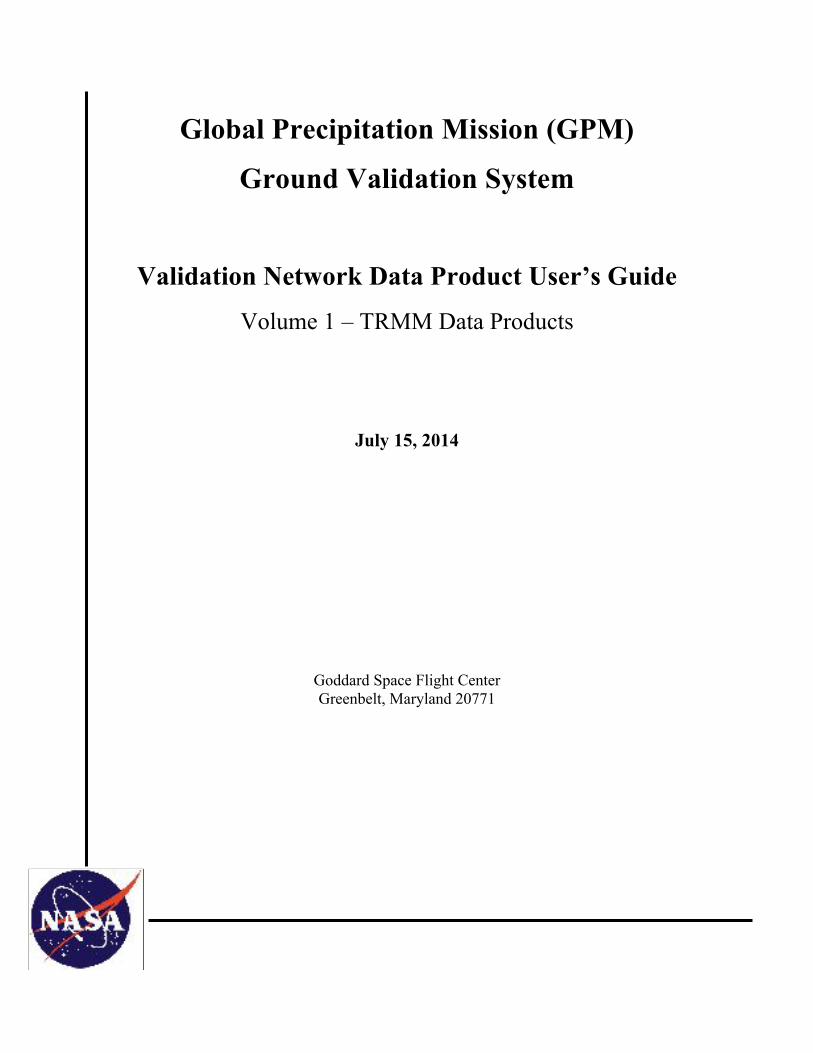
Document History
Document Version Date Changes
Draft January 12, 2007 Initial draft
Draft 2 April 5, 2007
2nd Draft. Added REORDER grid documentation and updated PR and GV netCDF file format descriptions.
Draft 3 June 19, 2007 3rd draft. Added new grid variables to GV netCDF file format description.
Version 1 August 13, 2007 Removed Draft designation. Added 2b-31 mention to PRgrids section.
Version 1.1 July 8, 2008
Updated path to netCDF files for new GPMGV FTP site. Corrected description of lat and lon variables for GVgridsREO (REORDER) netCDF files. Other minor edits and corrections.
Version 1.2 August 11, 2008
- Updated to reflect that tar files organized either by month or by site are now stored on the ftp site in separate directories. - Described the new criteria by which significant rain events are defined in the VN. - Changed “NEXRAD” references to “WSR-88D” in the text. - Added the location information for “other” participating sites: ARMOR/UAH, Darwin/BOM, Gosan/KMA - Fixed KHTX latitude/longitude in Table 1-1.
Version 2 November 5, 2008
- Added material and sections to document the origin and content of netCDF files from the new geometry matching technique.
Version 2.1 November 5, 2008 - Revised Section 2 and added Table 6-3.
Validation Network Data User’s Guide, Vol. 1 July 15, 2014
Page iii
Document Version Date Changes
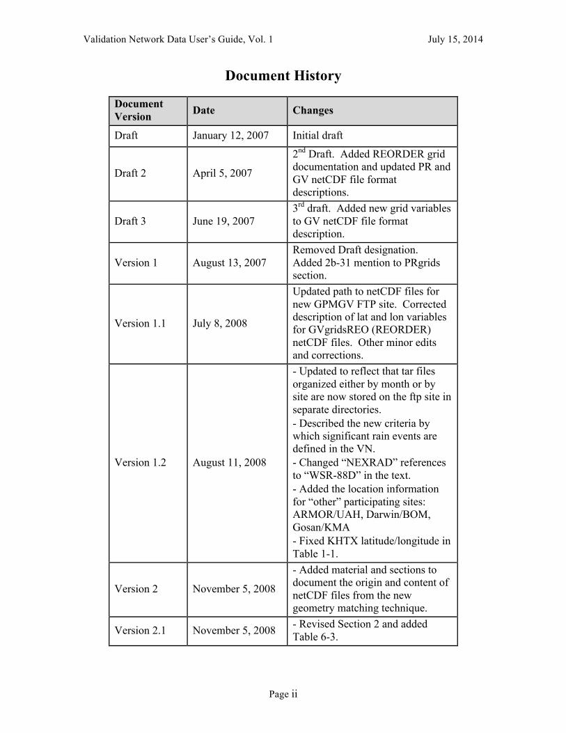
Version 2.2 September 19, 2009
- Added Section 4 on ftp site directory structure. Removed sections related to the gridded VN method which is no longer supported. Change GV to GR when referring to the ground radar.
Version 2.3 September 13, 2010
- Corrected table numbering of 7.1 and 7.2, changed to 3.1 and 3.2. Fixed table number references in text for these and other tables. - Added Note for Table 3.1 describing the Scan and Range Edge point optionality in Version 1.1 of the POLAR2PR code. - Added Note for Table 3.1 describing AGL vs. MSL units for height variables. - Added site_elev variable definition to the netCDF file summary, and a note indicating it applies to version 1.1 of the file. - Corrected ‘units’ attribute of the BBheight variable, should have been ‘m’, not ‘km’. - Added missing Bold/Italics formatting to VN ftp site directory tree structure.
Version 3 January 5, 2011
- Describes Version 2.0 of the geometry match netCDF files, which adds four new data variables and their ‘presence’ flags: have_threeDreflectMax have_threeDreflectStdDev have_BBstatus have_status threeDreflectMax threeDreflectStdDev BBstatus status
Validation Network Data User’s Guide, Vol. 1 July 15, 2014
Page iv
Document Version Date Changes
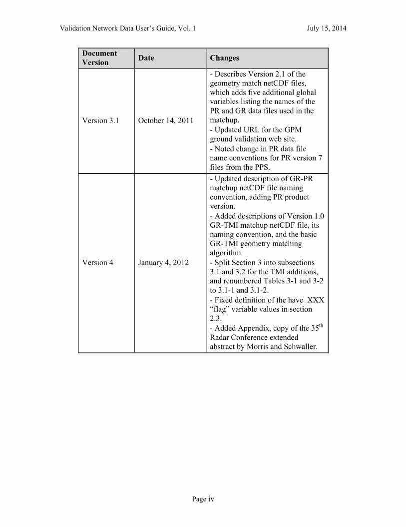
Version 3.1 October 14, 2011
- Describes Version 2.1 of the geometry match netCDF files, which adds five additional global variables listing the names of the PR and GR data files used in the matchup. - Updated URL for the GPM ground validation web site. - Noted change in PR data file name conventions for PR version 7 files from the PPS.
Version 4 January 4, 2012
- Updated description of GR-PR matchup netCDF file naming convention, adding PR product version. - Added descriptions of Version 1.0 GR-TMI matchup netCDF file, its naming convention, and the basic GR-TMI geometry matching algorithm. - Split Section 3 into subsections 3.1 and 3.2 for the TMI additions, and renumbered Tables 3-1 and 3-2 to 3.1-1 and 3.1-2. - Fixed definition of the have_XXX “flag” variable values in section 2.3. - Added Appendix, copy of the 35th Radar Conference extended abstract by Morris and Schwaller.
Validation Network Data User’s Guide, Vol. 1 July 15, 2014
Page v
Document Version Date Changes
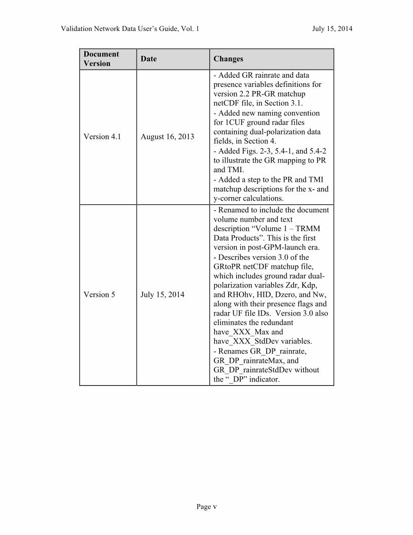
Version 4.1 August 16, 2013
- Added GR rainrate and data presence variables definitions for version 2.2 PR-GR matchup netCDF file, in Section 3.1. - Added new naming convention for 1CUF ground radar files containing dual-polarization data fields, in Section 4. - Added Figs. 2-3, 5.4-1, and 5.4-2 to illustrate the GR mapping to PR and TMI. - Added a step to the PR and TMI matchup descriptions for the x- and y-corner calculations.
Version 5 July 15, 2014
- Renamed to include the document volume number and text description “Volume 1 – TRMM Data Products”. This is the first version in post-GPM-launch era. - Describes version 3.0 of the GRtoPR netCDF matchup file, which includes ground radar dual-polarization variables Zdr, Kdp, and RHOhv, HID, Dzero, and Nw, along with their presence flags and radar UF file IDs. Version 3.0 also eliminates the redundant have_XXX_Max and have_XXX_StdDev variables. - Renames GR_DP_rainrate, GR_DP_rainrateMax, and GR_DP_rainrateStdDev without the “_DP” indicator.

Validation Network Data User’s Guide, Vol. 1 July 15, 2014
Page vi
Contact Information
Additional information, including information on VN points-of-contact, can be obtained from the GPM Ground Validation web site:
http://pmm.nasa.gov/science/ground-validation
Validation Network Data User’s Guide, Vol. 1 July 15, 2014
Page vii
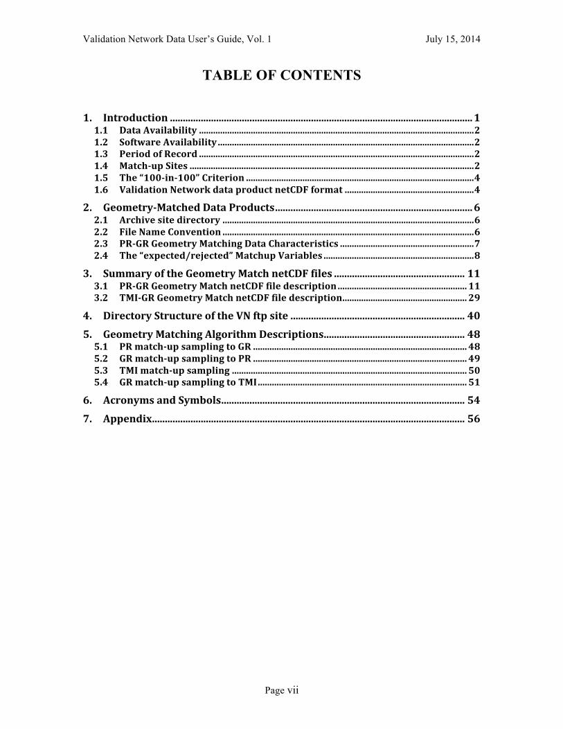
TABLE OF CONTENTS
1.! Introduction!......................................................................................................................!1!1.1! Data!Availability!.....................................................................................................................!2!1.2! Software!Availability!.............................................................................................................!2!1.3! Period!of!Record!.....................................................................................................................!2!1.4! Match?up!Sites!.........................................................................................................................!2!1.5! The!“100?in?100”!Criterion!.................................................................................................!4!1.6! Validation!Network!data!product!netCDF!format!.......................................................!4!
2.! Geometry?Matched!Data!Products!.............................................................................!6!2.1! Archive!site!directory!...........................................................................................................!6!2.2! File!Name!Convention!...........................................................................................................!6!2.3! PR?GR!Geometry!Matching!Data!Characteristics!.........................................................!7!2.4! The!“expected/rejected”!Matchup!Variables!................................................................!8!
3.! Summary!of!the!Geometry!Match!netCDF!files!...................................................!11!3.1! PR?GR!Geometry!Match!netCDF!file!description!.......................................................!11!3.2! TMI?GR!Geometry!Match!netCDF!file!description!.....................................................!29!
4.! Directory!Structure!of!the!VN!ftp!site!....................................................................!40!5.! Geometry!Matching!Algorithm!Descriptions!.......................................................!48!5.1! PR!match?up!sampling!to!GR!...........................................................................................!48!5.2! GR!match?up!sampling!to!PR!...........................................................................................!49!5.3! TMI!match?up!sampling!....................................................................................................!50!5.4! GR!match?up!sampling!to!TMI!.........................................................................................!51!
6.! Acronyms!and!Symbols!...............................................................................................!54!7.! Appendix!..........................................................................................................................!56!
Validation Network Data User’s Guide, Vol. 1 July 15, 2014
Page 1
1. Introduction
This document provides a basic set of documentation for the data products available from the GPM Ground Validation System (GVS) Validation Network (VN). In the GPM era the VN performs a direct match-up of GPM’s space-based Dual-frequency Precipitation Radar (DPR) data with ground radar data from the U.S. network of NOAA Weather Surveillance Radar-1988 Doppler (WSR-88D, or “NEXRAD”). Ground radar networks from international partners are also part of the VN. The VN match-up will help evaluate the radar reflectivity attenuation correction algorithms of the DPR and will identify biases between ground observations and satellite retrievals as they occur in different meteorological regimes. A prototype of the required capability was developed using a match-up of Tropical Rainfall Measuring Mission (TRMM) Precipitation Radar (PR) data with ground-based radar (GR) measurements from a set of WSR-88D sites, plus data from meteorological agency radars in Korea and Australia, and a university research radar in Huntsville, Alabama.
Two approaches to the PR-to-GR data matching have been developed. The original technique, described in earlier versions of this document, involves resampling PR and GR data to a fixed, common, 3-dimensional Cartesian grid centered on the GR site. This method, referred to as the gridding technique, is no longer actively supported as a VN method. Descriptions of this method are therefore not included in this document. A new (as of October, 2008) technique, the geometry matching technique, is based on determining the intersection of the individual PR rays with each of the elevation sweeps of the circularly-scanning ground radar. The horizontal and vertical locations and number of data points in the geometry matching technique are different for each case due to the randomness of the ray-to-sweep intersections. Section 5 of this document describes the algorithm used to generate geometry-matched data. Data output from the geometry matching technique are stored as netCDF files, with each netCDF file being specific to the TRMM overpass of an individual GR site.
A TRMM Microwave Imager (TMI)-to-GR geometry matching technique has also been developed. For this product, the TMI near-surface rain rate field is matched to the GR reflectivity field in two manners. First, the GR data are matched to the TMI at the intersections of the TMI line-of-sight with the GR elevation sweeps, in a similar manner to how the PR ray intersections with the GR sweeps are computed. Second, the GR sweep intersections with a vertical column above the TMI surface footprint are computed to give the vertical profile of GR reflectivity above the location where the TMI rain rate estimate is assigned in the TRMM 2A-12 product. The GPM Microwave Imager (GMI) data will replace the TMI data for GPM ground validation in the operational Validation Network. The utility of the TMI-GR or GMI-GR geometry match data has not been vetted by the GPM GMI algorithm developers and is to be considered an experimental product.

Validation Network Data User’s Guide, Vol. 1 July 15, 2014
Page 2
1.1 Data Availability
VN match-up, input, and ancillary data are available via anonymous ftp from this site: ftp://hector.gsfc.nasa.gov/gpm-validation/data. The site provides access to the raw TRMM PR and TMI data, raw ground radar data, quality controlled ground radar data, as well as geometrically matched PR-GR and TMI-GR data. The directory structure of the ftp site is described in detail in Section 4 of this document.
1.2 Software Availability Software to perform the PR-to-GR and TMI-to-GR geometry matching, and to display and compute PR-GR reflectivity and rainrate and TMI-GR rainrate statistics and analysis products from the data is available. Contact a member of the GPM GV team listed at http://pmm.nasa.gov/science/ground-validation.
1.3 Period of Record
The current period of record for the VN match-up datasets starts on August 8, 2006 and runs to the present. TRMM Version 7 PR and TMI products superseded the Version 6 products beginning in July, 2011. Data for all dates have been reprocessed to produce Version 7 products, so both Version 6 and 7 TRMM PR and TMI products are available prior to July, 2011. Because the input ground radar data for the VN match-ups are quality controlled by a human analyst there is a time lag of up to several weeks from observation to VN product generation.
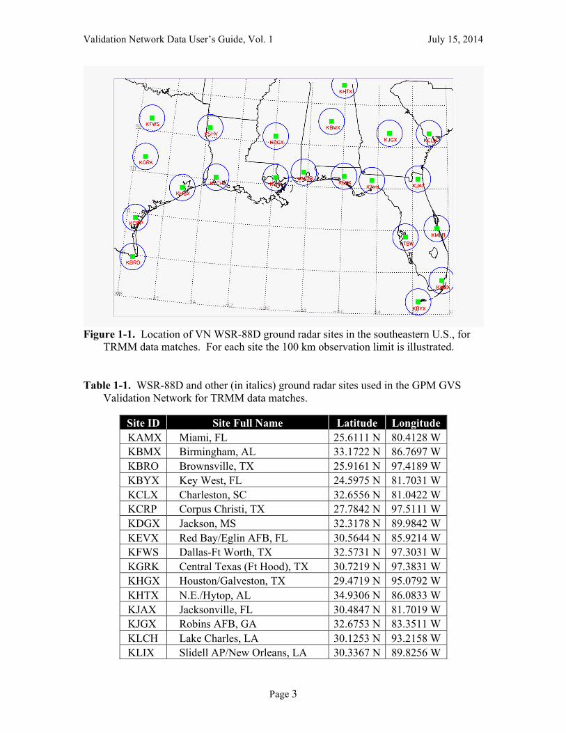
1.4 Match-up Sites
There are 21 WSR-88D sites included in the VN for TRMM data matchup processing. These are all located within the southeastern U.S. as illustrated in Figure 1-1. In addition to these WSR-88D sites, there are four additional GR sites with selected periods/dates of data included in the VN data set. These include the Darwin, Australia, Bureau of Meteorology CPOL (C-band polarimetric) radar (VN site ID: DARW); the ARMOR CPOL radar of University of Alabama, Huntsville (VN site ID: RMOR); the SPOL (S-band polarimetric) radar on Kwajalein atoll (KWAJ), and the Korean Meteorological Agency (KMA) S-band radar at Gosan, Jeju Island, South Korea (VN site ID: RGSN). Table 1-1 lists the VN site identifiers, long names, and the latitude and longitude of each. The VN short names are used in the VN product file naming convention described in Section 2 of this document. Although the list below was current at the time that this document was written, it is expected that additional VN sites will be added from time to time. More up-to-date information may be available on the GPM GV web site:
http://pmm.nasa.gov/science/ground-validation
Check with the GPM GV points-of-contact for current status.
Validation Network Data User’s Guide, Vol. 1 July 15, 2014
Page 3
Figure 1-1. Location of VN WSR-88D ground radar sites in the southeastern U.S., for
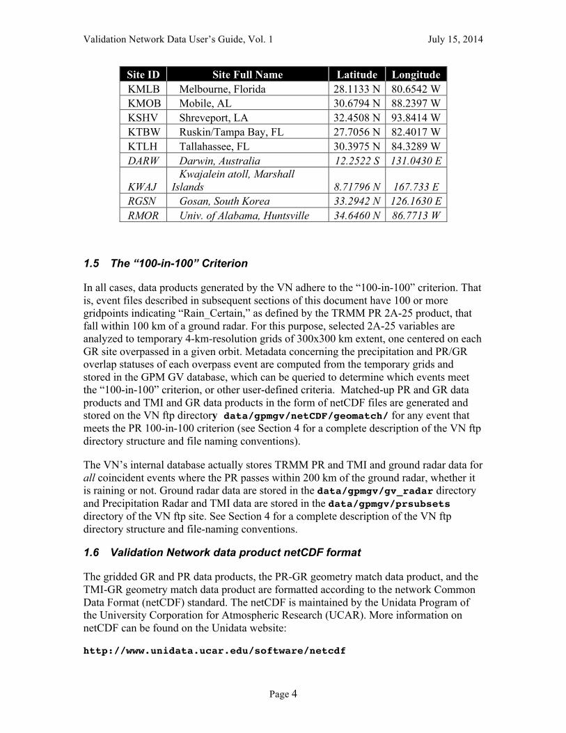
TRMM data matches. For each site the 100 km observation limit is illustrated. Table 1-1. WSR-88D and other (in italics) ground radar sites used in the GPM GVS
Validation Network for TRMM data matches.
Site ID Site Full Name Latitude Longitude KAMX Miami, FL 25.6111 N 80.4128 W KBMX Birmingham, AL 33.1722 N 86.7697 W KBRO Brownsville, TX 25.9161 N 97.4189 W KBYX Key West, FL 24.5975 N 81.7031 W KCLX Charleston, SC 32.6556 N 81.0422 W KCRP Corpus Christi, TX 27.7842 N 97.5111 W KDGX Jackson, MS 32.3178 N 89.9842 W KEVX Red Bay/Eglin AFB, FL 30.5644 N 85.9214 W KFWS Dallas-Ft Worth, TX 32.5731 N 97.3031 W KGRK Central Texas (Ft Hood), TX 30.7219 N 97.3831 W KHGX Houston/Galveston, TX 29.4719 N 95.0792 W KHTX N.E./Hytop, AL 34.9306 N 86.0833 W KJAX Jacksonville, FL 30.4847 N 81.7019 W KJGX Robins AFB, GA 32.6753 N 83.3511 W KLCH Lake Charles, LA 30.1253 N 93.2158 W KLIX Slidell AP/New Orleans, LA 30.3367 N 89.8256 W
Validation Network Data User’s Guide, Vol. 1 July 15, 2014
Page 4
Site ID Site Full Name Latitude Longitude KMLB Melbourne, Florida 28.1133 N 80.6542 W KMOB Mobile, AL 30.6794 N 88.2397 W KSHV Shreveport, LA 32.4508 N 93.8414 W KTBW Ruskin/Tampa Bay, FL 27.7056 N 82.4017 W KTLH Tallahassee, FL 30.3975 N 84.3289 W DARW Darwin, Australia 12.2522 S 131.0430 E
KWAJ Kwajalein atoll, Marshall
Islands 8.71796 N 167.733 E RGSN Gosan, South Korea 33.2942 N 126.1630 E RMOR Univ. of Alabama, Huntsville 34.6460 N 86.7713 W
1.5 The “100-in-100” Criterion
In all cases, data products generated by the VN adhere to the “100-in-100” criterion. That is, event files described in subsequent sections of this document have 100 or more gridpoints indicating “Rain_Certain,” as defined by the TRMM PR 2A-25 product, that fall within 100 km of a ground radar. For this purpose, selected 2A-25 variables are analyzed to temporary 4-km-resolution grids of 300x300 km extent, one centered on each GR site overpassed in a given orbit. Metadata concerning the precipitation and PR/GR overlap statuses of each overpass event are computed from the temporary grids and stored in the GPM GV database, which can be queried to determine which events meet the “100-in-100” criterion, or other user-defined criteria. Matched-up PR and GR data products and TMI and GR data products in the form of netCDF files are generated and stored on the VN ftp directory data/gpmgv/netCDF/geomatch/ for any event that meets the PR 100-in-100 criterion (see Section 4 for a complete description of the VN ftp directory structure and file naming conventions).
The VN’s internal database actually stores TRMM PR and TMI and ground radar data for all coincident events where the PR passes within 200 km of the ground radar, whether it is raining or not. Ground radar data are stored in the data/gpmgv/gv_radar directory and Precipitation Radar and TMI data are stored in the data/gpmgv/prsubsets directory of the VN ftp site. See Section 4 for a complete description of the VN ftp directory structure and file-naming conventions.
1.6 Validation Network data product netCDF format
The gridded GR and PR data products, the PR-GR geometry match data product, and the TMI-GR geometry match data product are formatted according to the network Common Data Format (netCDF) standard. The netCDF is maintained by the Unidata Program of the University Corporation for Atmospheric Research (UCAR). More information on netCDF can be found on the Unidata website:
http://www.unidata.ucar.edu/software/netcdf
Validation Network Data User’s Guide, Vol. 1 July 15, 2014
Page 5
There are three basic components of the netCDF files termed attributes, dimensions and variables, which are described briefly below.
Attributes contain auxiliary information about each netCDF variable. Each attribute has a name, data type and length associated with it. netCDF also permits the definition of global attributes, which typically apply to the data set as a whole, rather than to individual variables in the data. The PR-GR netCDF matchup files contain seven global attributes, and the TMI-GR netCDF matchup files contain four.
Dimensions are named integers that are use to specify the size (dimensionality) of one or more variables.
Variables are scalars or multidimensional arrays of values of the same data type. Each variable has a size, type and name associated with it. Variables also typically have attributes that describe them.
Validation Network Data User’s Guide, Vol. 1 July 15, 2014
Page 6
2. Geometry-Matched Data Products
2.1 Archive site directory
As previously described in Section 1.1, VN match-up data are available via anonymous ftp from:
ftp://hector.gsfc.nasa.gov/gpm-validation/data/gpmgv
Data from the geometry-matching techniques are located under the subdirectory netcdf/geo_match. The geometry-matching technique allows for comparison of actual space and ground network measurements (i.e., data are not resampled in 3 dimensions). This method has replaced the heritage gridding technique, which is no longer used as a VN data comparison method.
2.2 File Name Convention Geometry matching data in the netcdf/geo_match directory are stored as netCDF gzip-ped files, individualized by site (4-letter site ID, see Table 1-1), event date, and orbit number (see Section 4). These files will contain data for roughly the same set of events as the grid data, for a given event, since the “100-in-100” criteria described above are used to determine the events for which geometry-matching data are computed. The data volume of each file varies depending on the number of ”rainy” points in each file, but files of 10 to 100 or more MByte are typical.
The site-specific gzip file unpacks to a netCDF-format file identifiable by matchup TRMM data type (PR or TMI), GR site, date, TRMM orbit number, TRMM product version, and geometry match file version according to the file naming convention:
GRtoXXX.SHORTNAME.YYMMDD.ORBITNUMBER.V.F_f.nc.gz where: GRtoXXX = matchup type, literally either GRtoPR or GRtoTMI SHORTNAME = 4-character GR site ID (see Table 1-1) YY = 2-digit year MM = 2-digit month DD = 2-digit day (in UTM) ORBITNUMBER = 5-digit TRMM orbit number. V = 1-digit TRMM processing product version (6 or 7) F_f = Geometry match file Major/minor file version indicator, e.g. 2_1
for version 2.1 matchup file
The .nc designation indicates that the files are in the netCDF format. The .gz extension, if present, indicates that the file is compressed using gzip.
Validation Network Data User’s Guide, Vol. 1 July 15, 2014
Page 7
Each GRtoPR file type includes TRMM PR and ground radar data stored in netCDF format as described in Section 3 of this document. PR reflectivity and rain rate data are obtained from the standard TRMM products as follows: • Raw PR radar reflectivity (Zr) from TRMM product 1C-21. • Attenuation-Corrected PR radar reflectivity (Zc) from TRMM product 2A-25. • 3-D and Near-Surface Rain rate (mm/hr) from TRMM product 2A-25.
A land/ocean flag, near-surface rain rate, bright band height, rain type, rain/no-rain flag and other variables are also included from PR products 1C-21, 2A-23, and 2A-25. See the geometry-match netCDF file summary in Section 3.
Ground radar data included in these files are derived from the horizontal-sweep-scanning radar data that has been quality-controlled and processed into an intermediate 1C-UF product data file in Universal Format (UF).
Geometry matchup of the PR and ground radar data is performed using methods based on those described by Bolen and Chandrasekar1. See Section 5 for algorithm details.
2.3 PR-GR Geometry Matching Data Characteristics
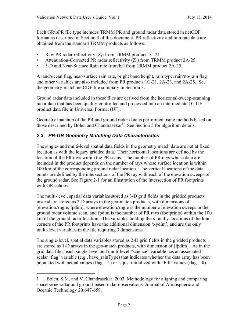
The single- and multi-level spatial data fields in the geometry match data are not at fixed location as with the legacy gridded data. Their horizontal locations are defined by the location of the PR rays within the PR scans. The number of PR rays whose data are included in the product depends on the number of rays whose surface location is within 100 km of the corresponding ground radar location. The vertical locations of the data points are defined by the intersections of the PR ray with each of the elevation sweeps of the ground radar. See Figure 2-1 for an illustration of the intersection of PR footprints with GR echoes.
The multi-level, spatial data variables stored as 3-D grid fields in the gridded products instead are stored as 2-D arrays in the geo-match products, with dimensions of [elevationAngle, fpdim], where elevationAngle is the number of elevation sweeps in the ground radar volume scan, and fpdim is the number of PR rays (footprints) within the 100 km of the ground radar location. The variables holding the x- and y-locations of the four corners of the PR footprints have the additional dimension ‘xydim’, and are the only multi-level variables in the file requiring 3 dimensions.
The single-level, spatial data variables stored as 2-D grid fields in the gridded products are stored as 1-D arrays in the geo-match products, with dimension of [fpdim]. As in the grid data files, each single-level and multi-level “science” variable has an associated scalar ‘flag’ variable (e.g., have_rainType) that indicates whether the data array has been populated with actual values (flag = 1) or is just initialized with “Fill” values (flag = 0).
1 Bolen, S.M. and V. Chandrasekar. 2003. Methodology for aligning and comparing spaceborne radar and ground-based radar observations. Journal of Atmospheric and Oceanic Technology 20:647-659.
Validation Network Data User’s Guide, Vol. 1 July 15, 2014
Page 8
Figure 2-1. An illustration of the intersection between Ground Radar sweeps and Precipitation Radar footprints. Only a select number of radar echoes are illustrated in either case.
Since the horizontal and vertical positions of each data point in the geometry matching data set are essentially random, each data value of the spatial data variables has a set of associated horizontal and (for the multi-level variables) vertical position variables. All points have both a latitude and a longitude value, corrected for viewing angle in the case of the multi-level variables. The multi-level variables also have associated variables specifying the x- and y-corners of the PR footprint for data plotting purposes (in km, relative to a Cartesian coordinate system centered at the location of the ground radar, with the +y axis pointing due north), and the top and bottom height of the ground radar elevation sweep at the PR ray intersection point, in km above the surface. A summary is provided in Section 3 of this document of all dimensions, attributes, and variables in the Geometry Matching netCDF files.
2.4 The “expected/rejected” Matchup Variables
One set of PR-GR geometry match variables in the netCDF files is concerned with the coincidence of ground radar (GR) and satellite precipitation radar (PR) range gates. These variables provide a metric that can be used to assess the “goodness” of the matchup between the radars. These “expected/rejected” variables are described in some detail below, because their content and meaning may otherwise be difficult to understand. As for the other geometry matchup variables, valid values for categorical variables are listed in Section 3 of this document. The meaning of all other variables can be deduced from the complete list of the geometry matchup variables and their associated units, which can also be found in Section 3 of this document.
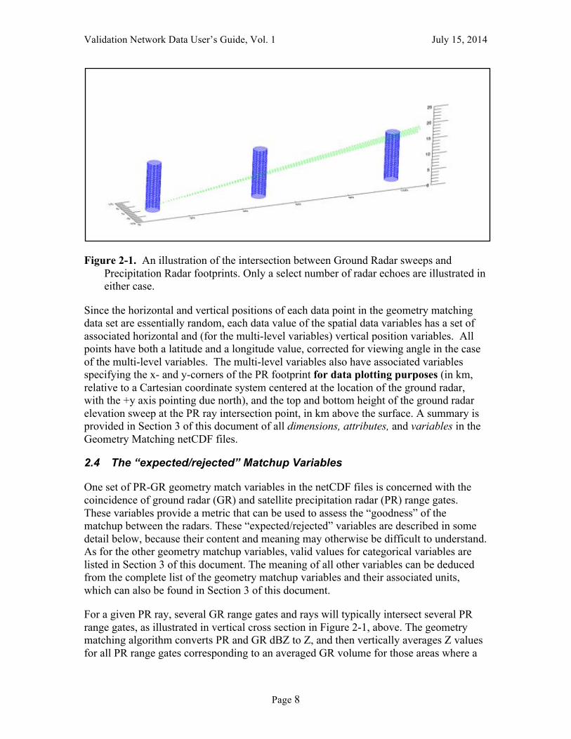
For a given PR ray, several GR range gates and rays will typically intersect several PR range gates, as illustrated in vertical cross section in Figure 2-1, above. The geometry matching algorithm converts PR and GR dBZ to Z, and then vertically averages Z values for all PR range gates corresponding to an averaged GR volume for those areas where a
Validation Network Data User’s Guide, Vol. 1 July 15, 2014
Page 9
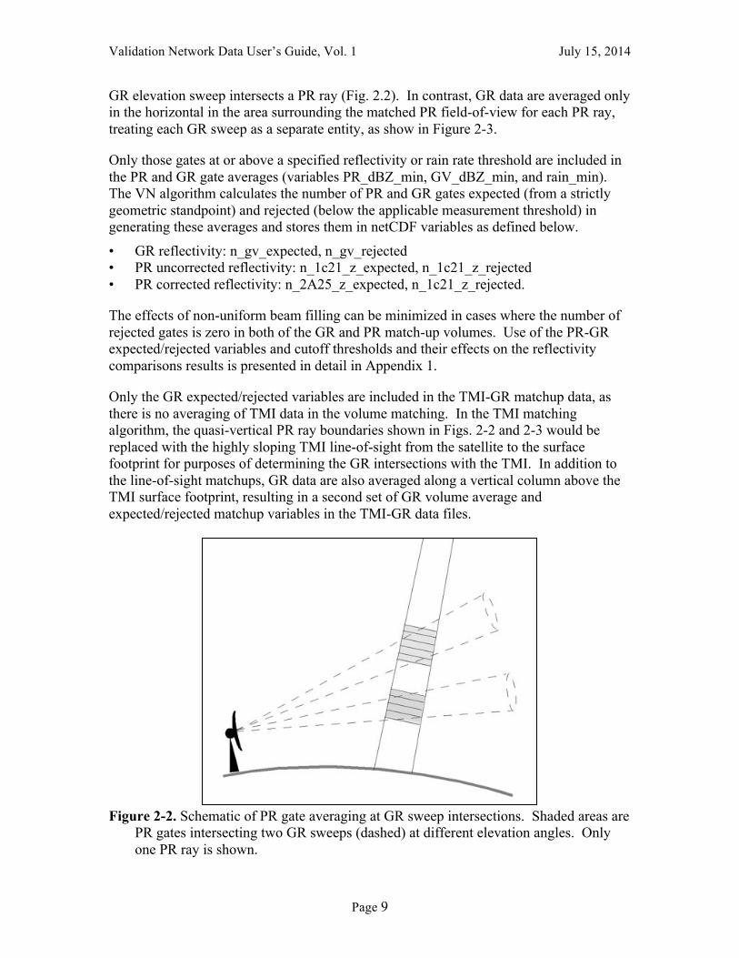
GR elevation sweep intersects a PR ray (Fig. 2.2). In contrast, GR data are averaged only in the horizontal in the area surrounding the matched PR field-of-view for each PR ray, treating each GR sweep as a separate entity, as show in Figure 2-3.
Only those gates at or above a specified reflectivity or rain rate threshold are included in the PR and GR gate averages (variables PR_dBZ_min, GV_dBZ_min, and rain_min). The VN algorithm calculates the number of PR and GR gates expected (from a strictly geometric standpoint) and rejected (below the applicable measurement threshold) in generating these averages and stores them in netCDF variables as defined below.
• GR reflectivity: n_gv_expected, n_gv_rejected • PR uncorrected reflectivity: n_1c21_z_expected, n_1c21_z_rejected • PR corrected reflectivity: n_2A25_z_expected, n_1c21_z_rejected.
The effects of non-uniform beam filling can be minimized in cases where the number of rejected gates is zero in both of the GR and PR match-up volumes. Use of the PR-GR expected/rejected variables and cutoff thresholds and their effects on the reflectivity comparisons results is presented in detail in Appendix 1.
Only the GR expected/rejected variables are included in the TMI-GR matchup data, as there is no averaging of TMI data in the volume matching. In the TMI matching algorithm, the quasi-vertical PR ray boundaries shown in Figs. 2-2 and 2-3 would be replaced with the highly sloping TMI line-of-sight from the satellite to the surface footprint for purposes of determining the GR intersections with the TMI. In addition to the line-of-sight matchups, GR data are also averaged along a vertical column above the TMI surface footprint, resulting in a second set of GR volume average and expected/rejected matchup variables in the TMI-GR data files.
Figure 2-2. Schematic of PR gate averaging at GR sweep intersections. Shaded areas are
PR gates intersecting two GR sweeps (dashed) at different elevation angles. Only one PR ray is shown.
Validation Network Data User’s Guide, Vol. 1 July 15, 2014
Page 10
Figure 2-3. Schematic representation of GR volume matching to PR. Square outline at surface, plotted from the x- and y-corners of the PR footprint stored in the matchup netCDF file, locates the surface intersection of a single PR ray whose centerline is shown as a vertical line. The "waffle" areas show the horizontal outline of GR gates mapped to the PR ray for each individual elevation sweep of the ground radar, which is located off the right side of the figure at X=0, Y=0, where X, Y, and Z are in km. Sloping lines are drawn between the GR sample volumes and the ground radar along the sweep surfaces. GR range gates are inverse-distance-weighted from the PR ray to compute the GR averages for the matching volumes. Vertical extent and overlap of the GR gates is not shown. GR azimuth/range resolution is 1° by 1 km in the plot.
Validation Network Data User’s Guide, Vol. 1 July 15, 2014
Page 11
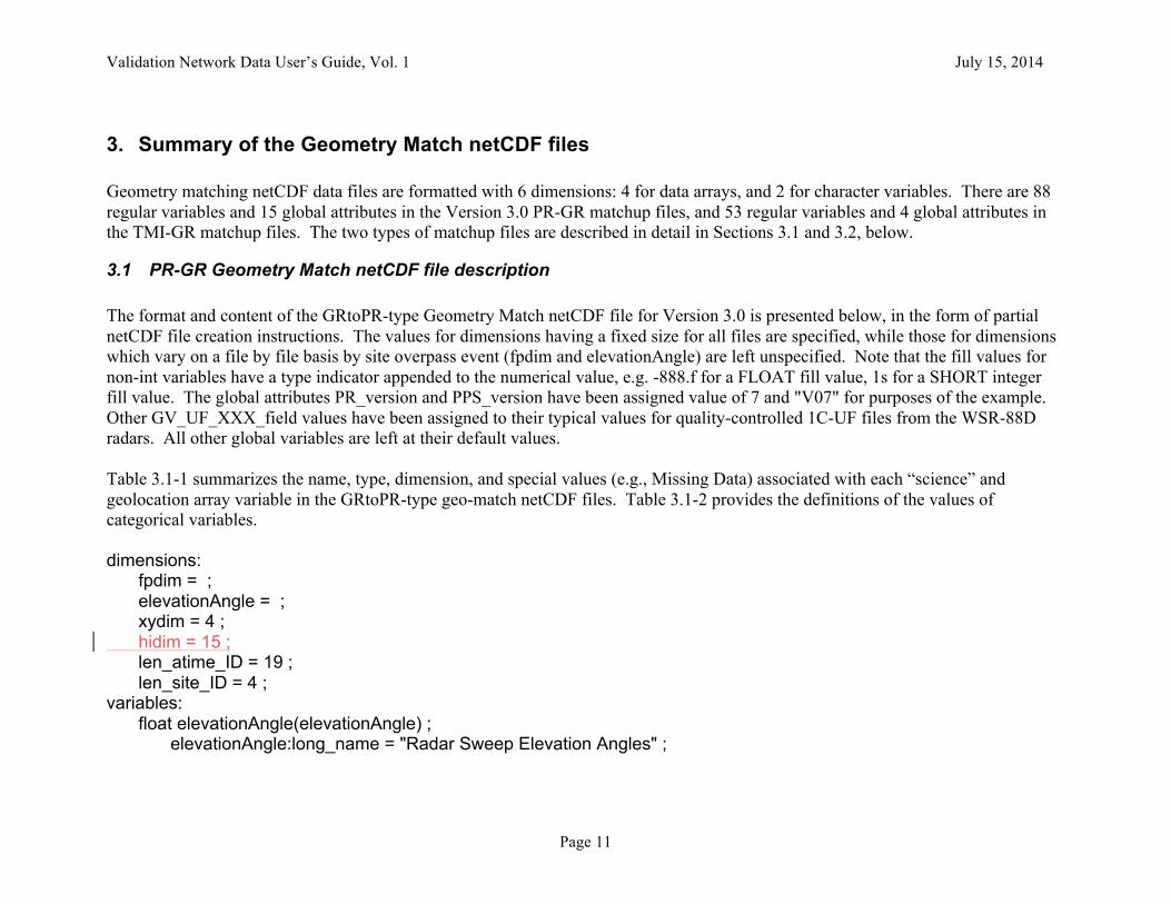
3. Summary of the Geometry Match netCDF files Geometry matching netCDF data files are formatted with 6 dimensions: 4 for data arrays, and 2 for character variables. There are 88 regular variables and 15 global attributes in the Version 3.0 PR-GR matchup files, and 53 regular variables and 4 global attributes in the TMI-GR matchup files. The two types of matchup files are described in detail in Sections 3.1 and 3.2, below.
3.1 PR-GR Geometry Match netCDF file description The format and content of the GRtoPR-type Geometry Match netCDF file for Version 3.0 is presented below, in the form of partial netCDF file creation instructions. The values for dimensions having a fixed size for all files are specified, while those for dimensions which vary on a file by file basis by site overpass event (fpdim and elevationAngle) are left unspecified. Note that the fill values for non-int variables have a type indicator appended to the numerical value, e.g. -888.f for a FLOAT fill value, 1s for a SHORT integer fill value. The global attributes PR_version and PPS_version have been assigned value of 7 and "V07" for purposes of the example. Other GV_UF_XXX_field values have been assigned to their typical values for quality-controlled 1C-UF files from the WSR-88D radars. All other global variables are left at their default values. Table 3.1-1 summarizes the name, type, dimension, and special values (e.g., Missing Data) associated with each “science” and geolocation array variable in the GRtoPR-type geo-match netCDF files. Table 3.1-2 provides the definitions of the values of categorical variables. dimensions: fpdim = ; elevationAngle = ; xydim = 4 ; hidim = 15 ; len_atime_ID = 19 ; len_site_ID = 4 ; variables: float elevationAngle(elevationAngle) ; elevationAngle:long_name = "Radar Sweep Elevation Angles" ;

Validation Network Data User’s Guide, Vol. 1 July 15, 2014
Page 12
elevationAngle:units = "degrees" ; float rangeThreshold ; rangeThreshold:long_name = "Dataset maximum range from radar site" ; rangeThreshold:_FillValue = -888.f ; rangeThreshold:units = "km" ; float PR_dBZ_min ; PR_dBZ_min:long_name = "minimum PR bin dBZ required for a *complete* PR vertical average" ; PR_dBZ_min:_FillValue = -888.f ; PR_dBZ_min:units = "dBZ" ; float GV_dBZ_min ; GV_dBZ_min:long_name = "minimum GV bin dBZ required for a *complete* GV horizontal average" ; GV_dBZ_min:_FillValue = -888.f ; GV_dBZ_min:units = "dBZ" ; float rain_min ; rain_min:long_name = "minimum PR rainrate required for a *complete* PR vertical average" ; rain_min:_FillValue = -888.f ; rain_min:units = "mm/h" ; short have_threeDreflect ; have_threeDreflect:long_name = "data exists flag for GR threeDreflect" ; have_threeDreflect:_FillValue = 0s ; short have_GR_Zdr ; have_GR_Zdr:long_name = "data exists flag for GR_Zdr" ; have_GR_Zdr:_FillValue = 0s ; short have_GR_Kdp ; have_GR_Kdp:long_name = "data exists flag for GR_Kdp" ; have_GR_Kdp:_FillValue = 0s ; short have_GR_RHOhv ; have_GR_RHOhv:long_name = "data exists flag for GR_RHOhv" ; have_GR_RHOhv:_FillValue = 0s ; short have_GR_rainrate ; have_GR_rainrate:long_name = "data exists flag for GR_rainrate" ;
Validation Network Data User’s Guide, Vol. 1 July 15, 2014
Page 13
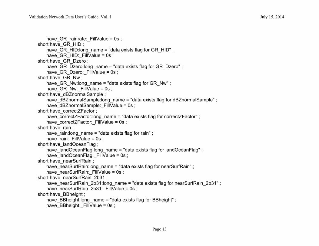
have_GR_rainrate:_FillValue = 0s ; short have_GR_HID ; have_GR_HID:long_name = "data exists flag for GR_HID" ; have_GR_HID:_FillValue = 0s ; short have_GR_Dzero ; have_GR_Dzero:long_name = "data exists flag for GR_Dzero" ; have_GR_Dzero:_FillValue = 0s ; short have_GR_Nw ; have_GR_Nw:long_name = "data exists flag for GR_Nw" ; have_GR_Nw:_FillValue = 0s ; short have_dBZnormalSample ; have_dBZnormalSample:long_name = "data exists flag for dBZnormalSample" ; have_dBZnormalSample:_FillValue = 0s ; short have_correctZFactor ; have_correctZFactor:long_name = "data exists flag for correctZFactor" ; have_correctZFactor:_FillValue = 0s ; short have_rain ; have_rain:long_name = "data exists flag for rain" ; have_rain:_FillValue = 0s ; short have_landOceanFlag ; have_landOceanFlag:long_name = "data exists flag for landOceanFlag" ; have_landOceanFlag:_FillValue = 0s ; short have_nearSurfRain ; have_nearSurfRain:long_name = "data exists flag for nearSurfRain" ; have_nearSurfRain:_FillValue = 0s ; short have_nearSurfRain_2b31 ; have_nearSurfRain_2b31:long_name = "data exists flag for nearSurfRain_2b31" ; have_nearSurfRain_2b31:_FillValue = 0s ; short have_BBheight ; have_BBheight:long_name = "data exists flag for BBheight" ; have_BBheight:_FillValue = 0s ;

Validation Network Data User’s Guide, Vol. 1 July 15, 2014
Page 14
short have_BBstatus ; have_BBstatus:long_name = "data exists flag for BBstatus" ; have_BBstatus:_FillValue = 0s ; short have_status ; have_status:long_name = "data exists flag for 2A23 status" ; have_status:_FillValue = 0s ; short have_rainFlag ; have_rainFlag:long_name = "data exists flag for rainFlag" ; have_rainFlag:_FillValue = 0s ; short have_rainType ; have_rainType:long_name = "data exists flag for rainType" ; have_rainType:_FillValue = 0s ; float latitude(elevationAngle, fpdim) ; latitude:long_name = "Latitude of data sample" ; latitude:units = "degrees North" ; latitude:_FillValue = -888.f ; float longitude(elevationAngle, fpdim) ; longitude:long_name = "Longitude of data sample" ; longitude:units = "degrees East" ; longitude:_FillValue = -888.f ; float xCorners(elevationAngle, fpdim, xydim) ; xCorners:long_name = "data sample x corner coords." ; xCorners:units = "km" ; xCorners:_FillValue = -888.f ; float yCorners(elevationAngle, fpdim, xydim) ; yCorners:long_name = "data sample y corner coords." ; yCorners:units = "km" ; yCorners:_FillValue = -888.f ; float topHeight(elevationAngle, fpdim) ; topHeight:long_name = "data sample top height AGL" ; topHeight:units = "km" ;
Validation Network Data User’s Guide, Vol. 1 July 15, 2014
Page 15
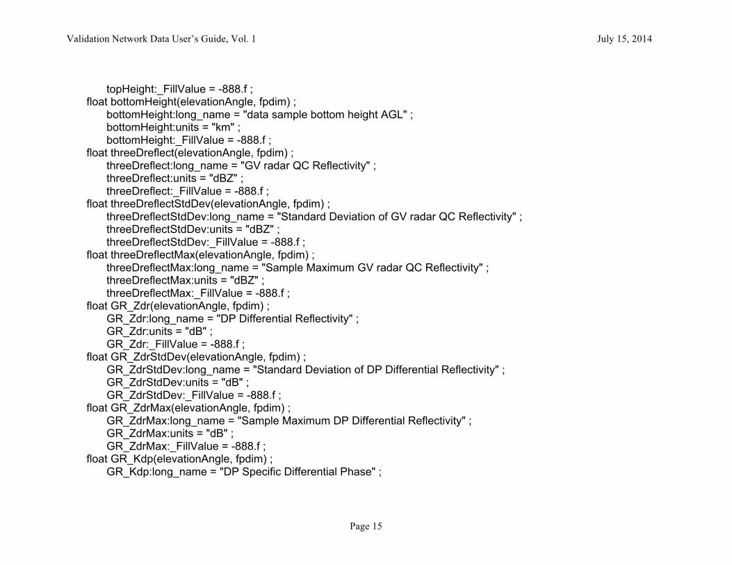
topHeight:_FillValue = -888.f ; float bottomHeight(elevationAngle, fpdim) ; bottomHeight:long_name = "data sample bottom height AGL" ; bottomHeight:units = "km" ; bottomHeight:_FillValue = -888.f ; float threeDreflect(elevationAngle, fpdim) ; threeDreflect:long_name = "GV radar QC Reflectivity" ; threeDreflect:units = "dBZ" ; threeDreflect:_FillValue = -888.f ; float threeDreflectStdDev(elevationAngle, fpdim) ; threeDreflectStdDev:long_name = "Standard Deviation of GV radar QC Reflectivity" ; threeDreflectStdDev:units = "dBZ" ; threeDreflectStdDev:_FillValue = -888.f ; float threeDreflectMax(elevationAngle, fpdim) ; threeDreflectMax:long_name = "Sample Maximum GV radar QC Reflectivity" ; threeDreflectMax:units = "dBZ" ; threeDreflectMax:_FillValue = -888.f ; float GR_Zdr(elevationAngle, fpdim) ; GR_Zdr:long_name = "DP Differential Reflectivity" ; GR_Zdr:units = "dB" ; GR_Zdr:_FillValue = -888.f ; float GR_ZdrStdDev(elevationAngle, fpdim) ; GR_ZdrStdDev:long_name = "Standard Deviation of DP Differential Reflectivity" ; GR_ZdrStdDev:units = "dB" ; GR_ZdrStdDev:_FillValue = -888.f ; float GR_ZdrMax(elevationAngle, fpdim) ; GR_ZdrMax:long_name = "Sample Maximum DP Differential Reflectivity" ; GR_ZdrMax:units = "dB" ; GR_ZdrMax:_FillValue = -888.f ; float GR_Kdp(elevationAngle, fpdim) ; GR_Kdp:long_name = "DP Specific Differential Phase" ;

Validation Network Data User’s Guide, Vol. 1 July 15, 2014
Page 16
GR_Kdp:units = "deg/km" ; GR_Kdp:_FillValue = -888.f ; float GR_KdpStdDev(elevationAngle, fpdim) ; GR_KdpStdDev:long_name = "Standard Deviation of DP Specific Differential Phase" ; GR_KdpStdDev:units = "deg/km" ; GR_KdpStdDev:_FillValue = -888.f ; float GR_KdpMax(elevationAngle, fpdim) ; GR_KdpMax:long_name = "Sample Maximum DP Specific Differential Phase" ; GR_KdpMax:units = "deg/km" ; GR_KdpMax:_FillValue = -888.f ; float GR_RHOhv(elevationAngle, fpdim) ; GR_RHOhv:long_name = "DP Co-Polar Correlation Coefficient" ; GR_RHOhv:units = "Dimensionless" ; GR_RHOhv:_FillValue = -888.f ; float GR_RHOhvStdDev(elevationAngle, fpdim) ; GR_RHOhvStdDev:long_name = "Standard Deviation of DP Co-Polar Correlation Coefficient" ; GR_RHOhvStdDev:units = "Dimensionless" ; GR_RHOhvStdDev:_FillValue = -888.f ; float GR_RHOhvMax(elevationAngle, fpdim) ; GR_RHOhvMax:long_name = "Sample Maximum DP Co-Polar Correlation Coefficient" ; GR_RHOhvMax:units = "Dimensionless" ; GR_RHOhvMax:_FillValue = -888.f ; float GR_rainrate(elevationAngle, fpdim) ; GR_rainrate:long_name = "GV radar DP Rainrate" ; GR_rainrate:units = "mm/h" ; GR_rainrate:_FillValue = -888.f ; float GR_rainrateStdDev(elevationAngle, fpdim) ; GR_rainrateStdDev:long_name = "Standard Deviation of GV radar DP Rainrate" ; GR_rainrateStdDev:units = "mm/h" ; GR_rainrateStdDev:_FillValue = -888.f ; float GR_rainrateMax(elevationAngle, fpdim) ;

Validation Network Data User’s Guide, Vol. 1 July 15, 2014
Page 17
GR_rainrateMax:long_name = "Sample Maximum GV radar DP Rainrate" ; GR_rainrateMax:units = "mm/h" ; GR_rainrateMax:_FillValue = -888.f ; short GR_HID(elevationAngle, fpdim, hidim) ; GR_HID:long_name = "DP Hydrometeor Identification" ; GR_HID:units = "Categorical" ; GR_HID:_FillValue = -888s ; float GR_Dzero(elevationAngle, fpdim) ; GR_Dzero:long_name = "DP Median Volume Diameter" ; GR_Dzero:units = "mm" ; GR_Dzero:_FillValue = -888.f ; float GR_DzeroStdDev(elevationAngle, fpdim) ; GR_DzeroStdDev:long_name = "Standard Deviation of DP Median Volume Diameter" ; GR_DzeroStdDev:units = "mm" ; GR_DzeroStdDev:_FillValue = -888.f ; float GR_DzeroMax(elevationAngle, fpdim) ; GR_DzeroMax:long_name = "Sample Maximum DP Median Volume Diameter" ; GR_DzeroMax:units = "mm" ; GR_DzeroMax:_FillValue = -888.f ; float GR_Nw(elevationAngle, fpdim) ; GR_Nw:long_name = "DP Normalized Intercept Parameter" ; GR_Nw:units = "1/(mm*m^3)" ; GR_Nw:_FillValue = -888.f ; float GR_NwStdDev(elevationAngle, fpdim) ; GR_NwStdDev:long_name = "Standard Deviation of DP Normalized Intercept Parameter" ; GR_NwStdDev:units = "1/(mm*m^3)" ; GR_NwStdDev:_FillValue = -888.f ; float GR_NwMax(elevationAngle, fpdim) ; GR_NwMax:long_name = "Sample Maximum DP Normalized Intercept Parameter" ; GR_NwMax:units = "1/(mm*m^3)" ; GR_NwMax:_FillValue = -888.f ;
Validation Network Data User’s Guide, Vol. 1 July 15, 2014
Page 18
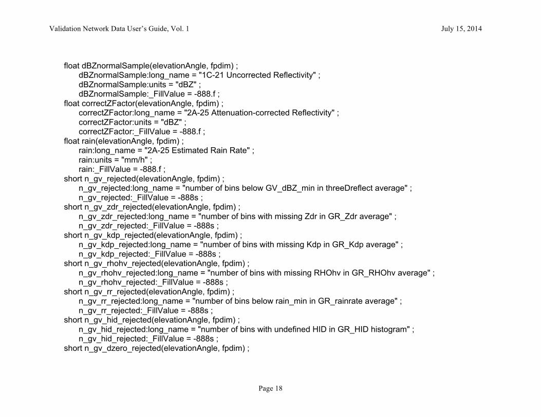
float dBZnormalSample(elevationAngle, fpdim) ; dBZnormalSample:long_name = "1C-21 Uncorrected Reflectivity" ; dBZnormalSample:units = "dBZ" ; dBZnormalSample:_FillValue = -888.f ; float correctZFactor(elevationAngle, fpdim) ; correctZFactor:long_name = "2A-25 Attenuation-corrected Reflectivity" ; correctZFactor:units = "dBZ" ; correctZFactor:_FillValue = -888.f ; float rain(elevationAngle, fpdim) ; rain:long_name = "2A-25 Estimated Rain Rate" ; rain:units = "mm/h" ; rain:_FillValue = -888.f ; short n_gv_rejected(elevationAngle, fpdim) ; n_gv_rejected:long_name = "number of bins below GV_dBZ_min in threeDreflect average" ; n_gv_rejected:_FillValue = -888s ; short n_gv_zdr_rejected(elevationAngle, fpdim) ; n_gv_zdr_rejected:long_name = "number of bins with missing Zdr in GR_Zdr average" ; n_gv_zdr_rejected:_FillValue = -888s ; short n_gv_kdp_rejected(elevationAngle, fpdim) ; n_gv_kdp_rejected:long_name = "number of bins with missing Kdp in GR_Kdp average" ; n_gv_kdp_rejected:_FillValue = -888s ; short n_gv_rhohv_rejected(elevationAngle, fpdim) ; n_gv_rhohv_rejected:long_name = "number of bins with missing RHOhv in GR_RHOhv average" ; n_gv_rhohv_rejected:_FillValue = -888s ; short n_gv_rr_rejected(elevationAngle, fpdim) ; n_gv_rr_rejected:long_name = "number of bins below rain_min in GR_rainrate average" ; n_gv_rr_rejected:_FillValue = -888s ; short n_gv_hid_rejected(elevationAngle, fpdim) ; n_gv_hid_rejected:long_name = "number of bins with undefined HID in GR_HID histogram" ; n_gv_hid_rejected:_FillValue = -888s ; short n_gv_dzero_rejected(elevationAngle, fpdim) ;

Validation Network Data User’s Guide, Vol. 1 July 15, 2014
Page 19
n_gv_dzero_rejected:long_name = "number of bins with missing D0 in GR_Dzero average" ; n_gv_dzero_rejected:_FillValue = -888s ; short n_gv_nw_rejected(elevationAngle, fpdim) ; n_gv_nw_rejected:long_name = "number of bins with missing Nw in GR_Nw average" ; n_gv_nw_rejected:_FillValue = -888s ; short n_gv_expected(elevationAngle, fpdim) ; n_gv_expected:long_name = "number of bins in GV Z and RR averages" ; n_gv_expected:_FillValue = -888s ; short n_1c21_z_rejected(elevationAngle, fpdim) ; n_1c21_z_rejected:long_name = "number of bins below PR_dBZ_min in dBZnormalSample average" ; n_1c21_z_rejected:_FillValue = -888s ; short n_2a25_z_rejected(elevationAngle, fpdim) ; n_2a25_z_rejected:long_name = "number of bins below PR_dBZ_min in correctZFactor average" ; n_2a25_z_rejected:_FillValue = -888s ; short n_2a25_r_rejected(elevationAngle, fpdim) ; n_2a25_r_rejected:long_name = "number of bins below rain_min in rain average" ; n_2a25_r_rejected:_FillValue = -888s ; short n_pr_expected(elevationAngle, fpdim) ; n_pr_expected:long_name = "number of bins in PR averages" ; n_pr_expected:_FillValue = -888s ; float PRlatitude(fpdim) ; PRlatitude:long_name = "Latitude of PR surface bin" ; PRlatitude:units = "degrees North" ; PRlatitude:_FillValue = -888.f ; float PRlongitude(fpdim) ; PRlongitude:long_name = "Longitude of PR surface bin" ; PRlongitude:units = "degrees East" ; PRlongitude:_FillValue = -888.f ; short landOceanFlag(fpdim) ; landOceanFlag:long_name = "1C-21 Land/Ocean Flag" ; landOceanFlag:units = "Categorical" ;
Validation Network Data User’s Guide, Vol. 1 July 15, 2014
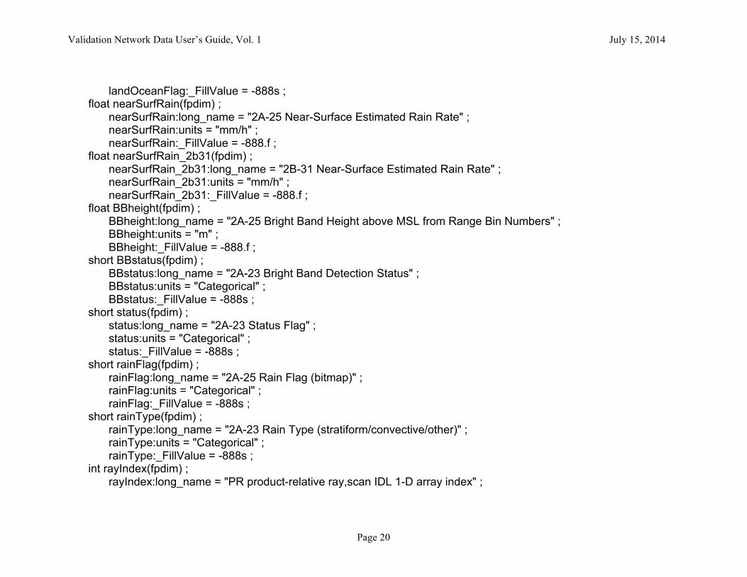
Page 20
landOceanFlag:_FillValue = -888s ; float nearSurfRain(fpdim) ; nearSurfRain:long_name = "2A-25 Near-Surface Estimated Rain Rate" ; nearSurfRain:units = "mm/h" ; nearSurfRain:_FillValue = -888.f ; float nearSurfRain_2b31(fpdim) ; nearSurfRain_2b31:long_name = "2B-31 Near-Surface Estimated Rain Rate" ; nearSurfRain_2b31:units = "mm/h" ; nearSurfRain_2b31:_FillValue = -888.f ; float BBheight(fpdim) ; BBheight:long_name = "2A-25 Bright Band Height above MSL from Range Bin Numbers" ; BBheight:units = "m" ; BBheight:_FillValue = -888.f ; short BBstatus(fpdim) ; BBstatus:long_name = "2A-23 Bright Band Detection Status" ; BBstatus:units = "Categorical" ; BBstatus:_FillValue = -888s ; short status(fpdim) ; status:long_name = "2A-23 Status Flag" ; status:units = "Categorical" ; status:_FillValue = -888s ; short rainFlag(fpdim) ; rainFlag:long_name = "2A-25 Rain Flag (bitmap)" ; rainFlag:units = "Categorical" ; rainFlag:_FillValue = -888s ; short rainType(fpdim) ; rainType:long_name = "2A-23 Rain Type (stratiform/convective/other)" ; rainType:units = "Categorical" ; rainType:_FillValue = -888s ; int rayIndex(fpdim) ; rayIndex:long_name = "PR product-relative ray,scan IDL 1-D array index" ;
Validation Network Data User’s Guide, Vol. 1 July 15, 2014
Page 21
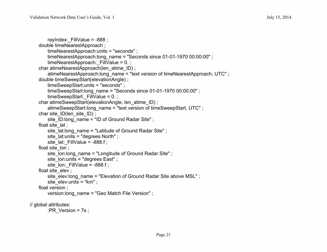
rayIndex:_FillValue = -888 ; double timeNearestApproach ; timeNearestApproach:units = "seconds" ; timeNearestApproach:long_name = "Seconds since 01-01-1970 00:00:00" ; timeNearestApproach:_FillValue = 0. ; char atimeNearestApproach(len_atime_ID) ; atimeNearestApproach:long_name = "text version of timeNearestApproach, UTC" ; double timeSweepStart(elevationAngle) ; timeSweepStart:units = "seconds" ; timeSweepStart:long_name = "Seconds since 01-01-1970 00:00:00" ; timeSweepStart:_FillValue = 0. ; char atimeSweepStart(elevationAngle, len_atime_ID) ; atimeSweepStart:long_name = "text version of timeSweepStart, UTC" ; char site_ID(len_site_ID) ; site_ID:long_name = "ID of Ground Radar Site" ; float site_lat ; site_lat:long_name = "Latitude of Ground Radar Site" ; site_lat:units = "degrees North" ; site_lat:_FillValue = -888.f ; float site_lon ; site_lon:long_name = "Longitude of Ground Radar Site" ; site_lon:units = "degrees East" ; site_lon:_FillValue = -888.f ; float site_elev ; site_elev:long_name = "Elevation of Ground Radar Site above MSL" ; site_elev:units = "km" ; float version ; version:long_name = "Geo Match File Version" ; // global attributes: :PR_Version = 7s ;
Validation Network Data User’s Guide, Vol. 1 July 15, 2014
Page 22
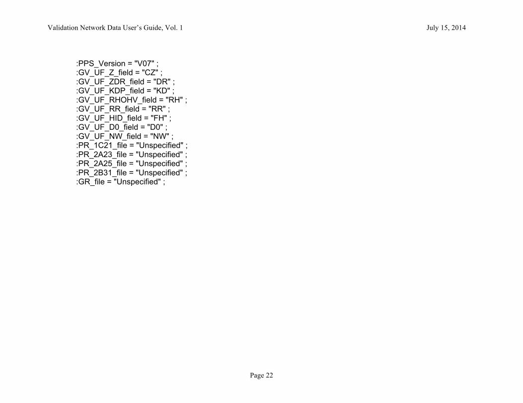
:PPS_Version = "V07" ; :GV_UF_Z_field = "CZ" ; :GV_UF_ZDR_field = "DR" ; :GV_UF_KDP_field = "KD" ; :GV_UF_RHOHV_field = "RH" ; :GV_UF_RR_field = "RR" ; :GV_UF_HID_field = "FH" ; :GV_UF_D0_field = "D0" ; :GV_UF_NW_field = "NW" ;
:PR_1C21_file = "Unspecified" ; :PR_2A23_file = "Unspecified" ; :PR_2A25_file = "Unspecified" ; :PR_2B31_file = "Unspecified" ; :GR_file = "Unspecified" ;
Validation Network Data User’s Guide, Vol. 1 July 15, 2014
Page 23
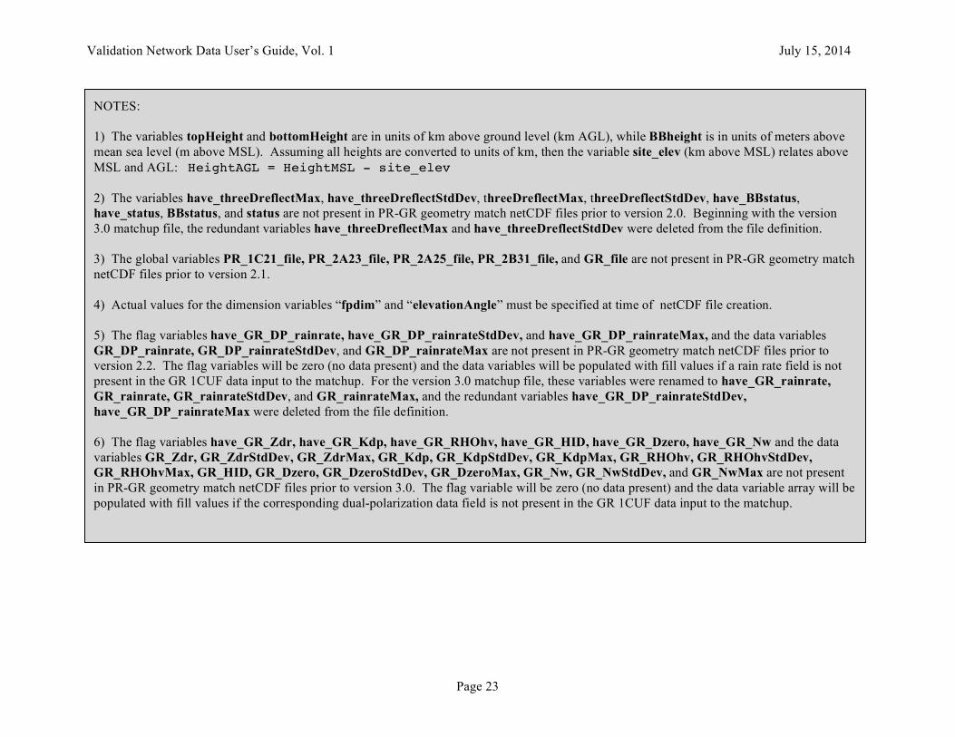
NOTES: 1) The variables topHeight and bottomHeight are in units of km above ground level (km AGL), while BBheight is in units of meters above mean sea level (m above MSL). Assuming all heights are converted to units of km, then the variable site_elev (km above MSL) relates above MSL and AGL: HeightAGL = HeightMSL - site_elev 2) The variables have_threeDreflectMax, have_threeDreflectStdDev, threeDreflectMax, threeDreflectStdDev, have_BBstatus, have_status, BBstatus, and status are not present in PR-GR geometry match netCDF files prior to version 2.0. Beginning with the version 3.0 matchup file, the redundant variables have_threeDreflectMax and have_threeDreflectStdDev were deleted from the file definition. 3) The global variables PR_1C21_file, PR_2A23_file, PR_2A25_file, PR_2B31_file, and GR_file are not present in PR-GR geometry match netCDF files prior to version 2.1. 4) Actual values for the dimension variables “fpdim” and “elevationAngle” must be specified at time of netCDF file creation. 5) The flag variables have_GR_DP_rainrate, have_GR_DP_rainrateStdDev, and have_GR_DP_rainrateMax, and the data variables GR_DP_rainrate, GR_DP_rainrateStdDev, and GR_DP_rainrateMax are not present in PR-GR geometry match netCDF files prior to version 2.2. The flag variables will be zero (no data present) and the data variables will be populated with fill values if a rain rate field is not present in the GR 1CUF data input to the matchup. For the version 3.0 matchup file, these variables were renamed to have_GR_rainrate, GR_rainrate, GR_rainrateStdDev, and GR_rainrateMax, and the redundant variables have_GR_DP_rainrateStdDev, have_GR_DP_rainrateMax were deleted from the file definition. 6) The flag variables have_GR_Zdr, have_GR_Kdp, have_GR_RHOhv, have_GR_HID, have_GR_Dzero, have_GR_Nw and the data variables GR_Zdr, GR_ZdrStdDev, GR_ZdrMax, GR_Kdp, GR_KdpStdDev, GR_KdpMax, GR_RHOhv, GR_RHOhvStdDev, GR_RHOhvMax, GR_HID, GR_Dzero, GR_DzeroStdDev, GR_DzeroMax, GR_Nw, GR_NwStdDev, and GR_NwMax are not present in PR-GR geometry match netCDF files prior to version 3.0. The flag variable will be zero (no data present) and the data variable array will be populated with fill values if the corresponding dual-polarization data field is not present in the GR 1CUF data input to the matchup.
Validation Network Data User’s Guide, Vol. 1 July 15, 2014
Page 24
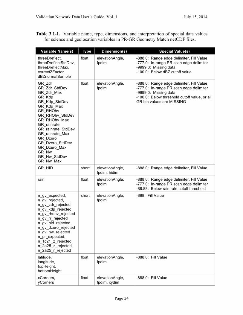
Table 3.1-1. Variable name, type, dimensions, and interpretation of special data values for science and geolocation variables in PR-GR Geometry Match netCDF files.
Variable Name(s) Type Dimension(s) Special Value(s)
threeDreflect, threeDreflectStdDev, threeDreflectMax, correctZFactor dBZnormalSample
float elevationAngle, fpdim
-888.0: Range edge delimiter, Fill Value -777.0: In-range PR scan edge delimiter -9999.0: Missing data -100.0: Below dBZ cutoff value
GR_Zdr GR_Zdr_StdDev GR_Zdr_Max GR_Kdp GR_Kdp_StdDev GR_Kdp_Max GR_RHOhv GR_RHOhv_StdDev GR_RHOhv_Max GR_rainrate GR_rainrate_StdDev GR_rainrate_Max GR_Dzero GR_Dzero_StdDev GR_Dzero_Max GR_Nw GR_Nw_StdDev GR_Nw_Max
float elevationAngle, fpdim
-888.0: Range edge delimiter, Fill Value -777.0: In-range PR scan edge delimiter -9999.0: Missing data -100.0: Below threshold cutoff value, or all GR bin values are MISSING
GR_HID short elevationAngle, fpdim, hidim
-888.0: Range edge delimiter, Fill Value
rain float elevationAngle, fpdim
-888.0: Range edge delimiter, Fill Value -777.0: In-range PR scan edge delimiter -88.88: Below rain rate cutoff threshold
n_gv_expected, n_gv_rejected, n_gv_zdr_rejected n_gv_kdp_rejected n_gv_rhohv_rejected n_gv_rr_rejected n_gv_hid_rejected n_gv_dzero_rejected n_gv_nw_rejected n_pr_expected, n_1c21_z_rejected, n_2a25_z_rejected, n_2a25_r_rejected
short elevationAngle, fpdim
-888: Fill Value
latitude, longitude, topHeight, bottomHeight
float elevationAngle, fpdim
-888.0: Fill Value
xCorners, yCorners
float elevationAngle, fpdim, xydim
-888.0: Fill Value
Validation Network Data User’s Guide, Vol. 1 July 15, 2014
Page 25
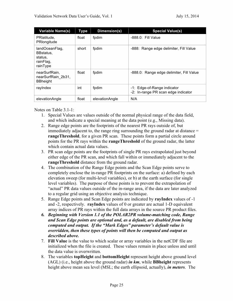
Variable Name(s) Type Dimension(s) Special Value(s)
PRlatitude, PRlongitude
float fpdim -888.0: Fill Value
landOceanFlag, BBstatus, status, rainFlag, rainType
short fpdim -888: Range edge delimiter, Fill Value
nearSurfRain, nearSurfRain_2b31, BBheight
float fpdim -888.0: Range edge delimiter, Fill Value
rayIndex int fpdim -1: Edge-of-Range indicator -2: In-range PR scan edge indicator
elevationAngle float elevationAngle N/A Notes on Table 3.1-1:
1. Special Values are values outside of the normal physical range of the data field, and which indicate a special meaning at the data point (e.g., Missing data).
2. Range edge points are the footprints of the nearest PR rays outside of, but immediately adjacent to, the range ring surrounding the ground radar at distance = rangeThreshold, for a given PR scan. These points form a partial circle around points for the PR rays within the rangeThreshold of the ground radar, the latter which contain actual data values.
3. PR scan edge points are the footprints of single PR rays extrapolated just beyond either edge of the PR scan, and which fall within or immediately adjacent to the rangeThreshold distance from the ground radar.
4. The combination of the Range Edge points and the Scan Edge points serve to completely enclose the in-range PR footprints on the surface: a) defined by each elevation sweep (for multi-level variables), or b) at the earth surface (for single level variables). The purpose of these points is to prevent the extrapolation of “actual” PR data values outside of the in-range area, if the data are later analyzed to a regular grid using an objective analysis technique.
5. Range Edge points and Scan Edge points are indicated by rayIndex values of -1 and -2, respectively. rayIndex values of 0 or greater are actual 1-D equivalent array indices of PR rays within the full data arrays in the source PR product files.
6. Beginning with Version 1.1 of the POLAR2PR volume-matching code, Range and Scan Edge points are optional and, as a default, are disabled from being computed and output. If the “Mark Edges” parameter’s default value is overridden, then these types of points will then be computed and output as described above.
7. Fill Value is the value to which scalar or array variables in the netCDF file are initialized when the file is created. These values remain in place unless and until the data value is overwritten.
8. The variables topHeight and bottomHeight represent height above ground level (AGL) (i.e., height above the ground radar) in km, while BBheight represents height above mean sea level (MSL; the earth ellipsoid, actually), in meters. The

Validation Network Data User’s Guide, Vol. 1 July 15, 2014
Page 26
difference between AGL height and MSL height is given by the value of the site_elev variable, the height above MSL of the ground radar, in km. To compare BBheight to topHeight or bottomHeight, first convert BBheight to km units. Then, either subtract site_elev from BBheight to work in AGL height units, or add site_elev to topHeight and bottomHeight to work in MSL height units. The site_elev variable is only available in files with a version value of 1.1 or greater.
9. GR_HID is not an average, it is an array of values representing a histogram that counts the number of GR range gates in each hydrometeor category (integer HID code), for those GR range gates geometrically matched to the PR footprint. The first array element counts the number of GR range bins where the HID category is MISSING. Array elements 2-12 give the number of GR bins in each HID category: 'UC' (unclassified), 'DZ' (drizzle), 'RN' (rain), 'CR' (ice crystals), 'DS' (dry snow/aggregates), 'WS' (wet snow), 'VI' (vertical ice), 'LDG' (low density graupel), 'HDG' (high density graupel), 'HA' (hail), 'BD' (big drops). Array elements 13-15 are spares at this time. GR_HID is available beginning with the Version 3.0 matchup netCDF file.
Validation Network Data User’s Guide, Vol. 1 July 15, 2014
Page 27
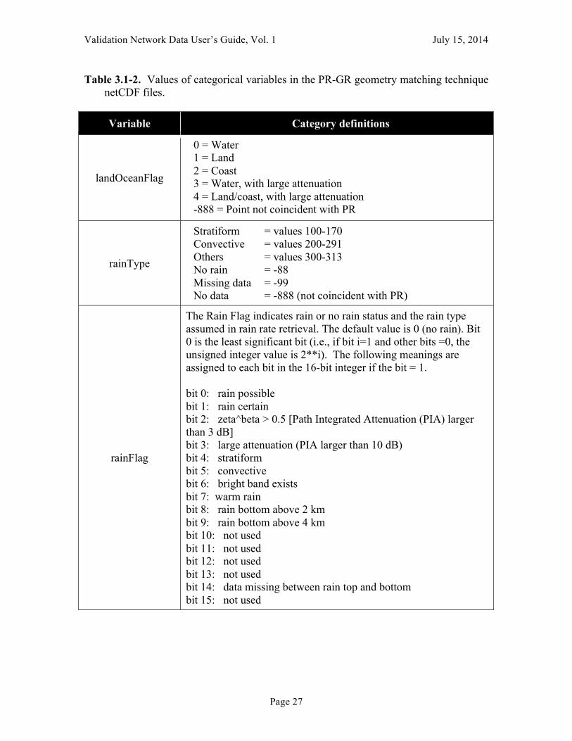
Table 3.1-2. Values of categorical variables in the PR-GR geometry matching technique netCDF files.
Variable Category definitions
landOceanFlag
0 = Water 1 = Land 2 = Coast 3 = Water, with large attenuation 4 = Land/coast, with large attenuation -888 = Point not coincident with PR
rainType
Stratiform = values 100-170 Convective = values 200-291 Others = values 300-313 No rain = -88 Missing data = -99 No data = -888 (not coincident with PR)
rainFlag
The Rain Flag indicates rain or no rain status and the rain type assumed in rain rate retrieval. The default value is 0 (no rain). Bit 0 is the least significant bit (i.e., if bit i=1 and other bits =0, the unsigned integer value is 2**i). The following meanings are assigned to each bit in the 16-bit integer if the bit = 1. bit 0: rain possible bit 1: rain certain bit 2: zeta^beta > 0.5 [Path Integrated Attenuation (PIA) larger than 3 dB] bit 3: large attenuation (PIA larger than 10 dB) bit 4: stratiform bit 5: convective bit 6: bright band exists bit 7: warm rain bit 8: rain bottom above 2 km bit 9: rain bottom above 4 km bit 10: not used bit 11: not used bit 12: not used bit 13: not used bit 14: data missing between rain top and bottom bit 15: not used
Validation Network Data User’s Guide, Vol. 1 July 15, 2014
Page 28
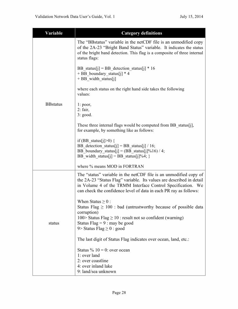
Variable Category definitions
BBstatus
The “BBstatus” variable in the netCDF file is an unmodified copy of the 2A-23 “Bright Band Status” variable. It indicates the status of the bright band detection. This flag is a composite of three internal status flags: BB_status[j] = BB_detection_status[j] * 16 + BB_boundary_status[j] * 4 + BB_width_status[j] where each status on the right hand side takes the following values: 1: poor, 2: fair, 3: good. These three internal flags would be computed from BB_status[j], for example, by something like as follows: if (BB_status[j]>0) { BB_detection_status[j] = BB_status[j] / 16; BB_boundary_status[j] = (BB_status[j]%16) / 4; BB_width_status[j] = BB_status[j]%4; } where % means MOD in FORTRAN
status
The “status” variable in the netCDF file is an unmodified copy of the 2A-23 “Status Flag” variable. Its values are described in detail in Volume 4 of the TRMM Interface Control Specification. We can check the confidence level of data in each PR ray as follows: When Status ≥ 0 : Status Flag ≥ 100 : bad (untrustworthy because of possible data corruption) 100> Status Flag ≥ 10 : result not so confident (warning) Status Flag = 9 : may be good 9> Status Flag ≥ 0 : good The last digit of Status Flag indicates over ocean, land, etc.: Status % 10 = 0: over ocean 1: over land 2: over coastline 4: over inland lake 9: land/sea unknown

Validation Network Data User’s Guide, Vol. 1 July 15, 2014
Page 29
3.2 TMI-GR Geometry Match netCDF file description The format and content of the GRtoTMI-type Geometry Match netCDF file is presented below, in the form of partial netCDF file creation instructions. See Section 3.1 for details related to dimensions and netCDF variable types. Table 3.2-1 summarizes the name, type, dimension, and special values (e.g., Missing Data) associated with each “science” and geolocation array variable in the GRtoTMI-type geometry match netCDF files. The GRtoGMI matchup file and algorithm will not be continued in the GPM era, but will be superseded by the geometry match of the GR data to the TRMM TMI 2A-GPROF product. See Vol. 2 of the Validation Network Data User’s Guide describing the GRtoGMI matchup data files, which applies to all satellite microwave imagers processed under the 2A-GPROF algorithm. dimensions: fpdim = ; elevationAngle = ; xydim = 4 ; len_atime_ID = 19 ; len_site_ID = 4 ; variables: float elevationAngle(elevationAngle) ; elevationAngle:long_name = "Radar Sweep Elevation Angles" ; elevationAngle:units = "degrees" ; float rangeThreshold ; rangeThreshold:long_name = "Dataset maximum range from radar site" ; rangeThreshold:_FillValue = -888.f ; rangeThreshold:units = "km" ; float GR_dBZ_min ; GR_dBZ_min:long_name = "minimum GR bin dBZ required for a *complete* GR horizontal average" ; GR_dBZ_min:_FillValue = -888.f ; GR_dBZ_min:units = "dBZ" ; float tmi_rain_min ; tmi_rain_min:long_name = "minimum TMI rainrate required" ;
Validation Network Data User’s Guide, Vol. 1 July 15, 2014
Page 30
tmi_rain_min:_FillValue = -888.f ; tmi_rain_min:units = "mm/h" ; float radiusOfInfluence ; radiusOfInfluence:long_name = "Radius of influence for distance weighting of GR bins" ; radiusOfInfluence:_FillValue = -888.f ; radiusOfInfluence:units = "km" ; short have_GR_Z_along_TMI ; have_GR_Z_along_TMI:long_name = "data exists flag for GR_Z_along_TMI" ; have_GR_Z_along_TMI:_FillValue = 0s ; short have_GR_Z_StdDev_along_TMI ; have_GR_Z_StdDev_along_TMI:long_name = "data exists flag for GR_Z_StdDev_along_TMI" ; have_GR_Z_StdDev_along_TMI:_FillValue = 0s ; short have_GR_Z_Max_along_TMI ; have_GR_Z_Max_along_TMI:long_name = "data exists flag for GR_Z_Max_along_TMI" ; have_GR_Z_Max_along_TMI:_FillValue = 0s ; short have_GR_Z_VPR ; have_GR_Z_VPR:long_name = "data exists flag for GR_Z_VPR" ; have_GR_Z_VPR:_FillValue = 0s ; short have_GR_Z_StdDev_VPR ; have_GR_Z_StdDev_VPR:long_name = "data exists flag for GR_Z_StdDev_VPR" ; have_GR_Z_StdDev_VPR:_FillValue = 0s ; short have_GR_Z_Max_VPR ; have_GR_Z_Max_VPR:long_name = "data exists flag for GR_Z_Max_VPR" ; have_GR_Z_Max_VPR:_FillValue = 0s ; short have_surfaceType ; have_surfaceType:long_name = "data exists flag for surfaceType" ; have_surfaceType:_FillValue = 0s ; short have_surfaceRain ; have_surfaceRain:long_name = "data exists flag for surfaceRain" ; have_surfaceRain:_FillValue = 0s ; short have_rainFlag ;
Validation Network Data User’s Guide, Vol. 1 July 15, 2014
Page 31
have_rainFlag:long_name = "data exists flag for rainFlag" ; have_rainFlag:_FillValue = 0s ; short have_dataFlag ; have_dataFlag:long_name = "data exists flag for dataFlag" ; have_dataFlag:_FillValue = 0s ; short have_PoP ; have_PoP:long_name = "data exists flag for PoP" ; have_PoP:_FillValue = 0s ; short have_freezingHeight ; have_freezingHeight:long_name = "data exists flag for freezingHeight" ; have_freezingHeight:_FillValue = 0s ; float latitude(elevationAngle, fpdim) ; latitude:long_name = "Latitude of data sample" ; latitude:units = "degrees North" ; latitude:_FillValue = -888.f ; float longitude(elevationAngle, fpdim) ; longitude:long_name = "Longitude of data sample" ; longitude:units = "degrees East" ; longitude:_FillValue = -888.f ; float xCorners(elevationAngle, fpdim, xydim) ; xCorners:long_name = "data sample x corner coords." ; xCorners:units = "km" ; xCorners:_FillValue = -888.f ; float yCorners(elevationAngle, fpdim, xydim) ; yCorners:long_name = "data sample y corner coords." ; yCorners:units = "km" ; yCorners:_FillValue = -888.f ; float topHeight(elevationAngle, fpdim) ; topHeight:long_name = "data sample top height AGL" ; topHeight:units = "km" ; topHeight:_FillValue = -888.f ;
Validation Network Data User’s Guide, Vol. 1 July 15, 2014
Page 32
float bottomHeight(elevationAngle, fpdim) ; bottomHeight:long_name = "data sample bottom height AGL" ; bottomHeight:units = "km" ; bottomHeight:_FillValue = -888.f ; float topHeight_vpr(elevationAngle, fpdim) ; topHeight_vpr:long_name = "data sample top height AGL along local vertical" ; topHeight_vpr:units = "km" ; topHeight_vpr:_FillValue = -888.f ; float bottomHeight_vpr(elevationAngle, fpdim) ; bottomHeight_vpr:long_name = "data sample bottom height AGL along local vertical" ; bottomHeight_vpr:units = "km" ; bottomHeight_vpr:_FillValue = -888.f ; float GR_Z_along_TMI(elevationAngle, fpdim) ; GR_Z_along_TMI:long_name = "GV radar QC Reflectivity" ; GR_Z_along_TMI:units = "dBZ" ; GR_Z_along_TMI:_FillValue = -888.f ; float GR_Z_StdDev_along_TMI(elevationAngle, fpdim) ; GR_Z_StdDev_along_TMI:long_name = "Standard Deviation of GV radar QC Reflectivity" ; GR_Z_StdDev_along_TMI:units = "dBZ" ; GR_Z_StdDev_along_TMI:_FillValue = -888.f ; float GR_Z_Max_along_TMI(elevationAngle, fpdim) ; GR_Z_Max_along_TMI:long_name = "Sample Maximum GV radar QC Reflectivity" ; GR_Z_Max_along_TMI:units = "dBZ" ; GR_Z_Max_along_TMI:_FillValue = -888.f ; short n_gr_rejected(elevationAngle, fpdim) ; n_gr_rejected:long_name = "number of bins below GR_dBZ_min in GR_Z_along_TMI average" ; n_gr_rejected:_FillValue = -888s ; short n_gr_expected(elevationAngle, fpdim) ; n_gr_expected:long_name = "number of bins in GR_Z_along_TMI average" ; n_gr_expected:_FillValue = -888s ; float GR_Z_VPR(elevationAngle, fpdim) ;
Validation Network Data User’s Guide, Vol. 1 July 15, 2014
Page 33
GR_Z_VPR:long_name = "GV radar QC Reflectivity along local vertical" ; GR_Z_VPR:units = "dBZ" ; GR_Z_VPR:_FillValue = -888.f ; float GR_Z_StdDev_VPR(elevationAngle, fpdim) ; GR_Z_StdDev_VPR:long_name = "Standard Deviation of GV radar QC Reflectivity along local vertical" ; GR_Z_StdDev_VPR:units = "dBZ" ; GR_Z_StdDev_VPR:_FillValue = -888.f ; float GR_Z_Max_VPR(elevationAngle, fpdim) ; GR_Z_Max_VPR:long_name = "Sample Maximum GV radar QC Reflectivity along local vertical" ; GR_Z_Max_VPR:units = "dBZ" ; GR_Z_Max_VPR:_FillValue = -888.f ; short n_gr_vpr_rejected(elevationAngle, fpdim) ; n_gr_vpr_rejected:long_name = "number of bins below GR_dBZ_min in GR_Z_VPR average" ; n_gr_vpr_rejected:_FillValue = -888s ; short n_gr_vpr_expected(elevationAngle, fpdim) ; n_gr_vpr_expected:long_name = "number of bins in GR_Z_VPR average" ; n_gr_vpr_expected:_FillValue = -888s ; float TMIlatitude(fpdim) ; TMIlatitude:long_name = "Latitude of TMI surface bin" ; TMIlatitude:units = "degrees North" ; TMIlatitude:_FillValue = -888.f ; float TMIlongitude(fpdim) ; TMIlongitude:long_name = "Longitude of TMI surface bin" ; TMIlongitude:units = "degrees East" ; TMIlongitude:_FillValue = -888.f ; short surfaceType(fpdim) ; surfaceType:long_name = "2A-12 Land/Ocean Flag" ; surfaceType:units = "Categorical" ; surfaceType:_FillValue = -888s ; float surfaceRain(fpdim) ; surfaceRain:long_name = "2A-12 Estimated Surface Rain Rate" ;
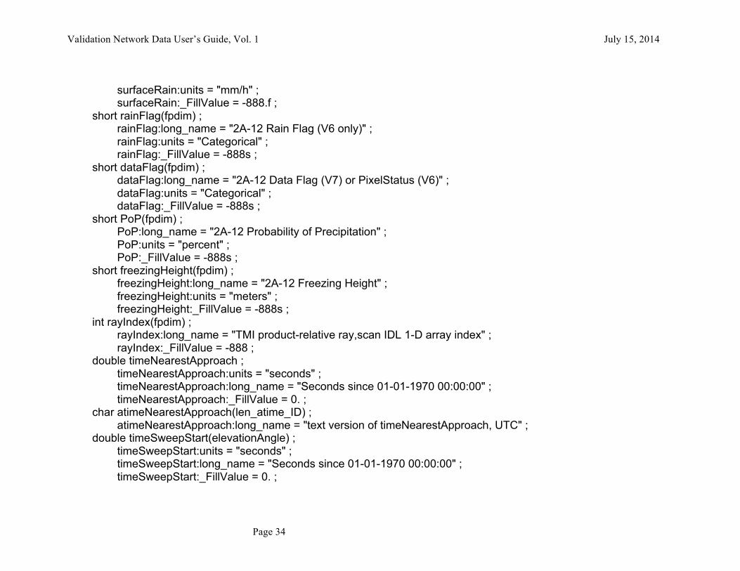
Validation Network Data User’s Guide, Vol. 1 July 15, 2014
Page 34
surfaceRain:units = "mm/h" ; surfaceRain:_FillValue = -888.f ; short rainFlag(fpdim) ; rainFlag:long_name = "2A-12 Rain Flag (V6 only)" ; rainFlag:units = "Categorical" ; rainFlag:_FillValue = -888s ; short dataFlag(fpdim) ; dataFlag:long_name = "2A-12 Data Flag (V7) or PixelStatus (V6)" ; dataFlag:units = "Categorical" ; dataFlag:_FillValue = -888s ; short PoP(fpdim) ; PoP:long_name = "2A-12 Probability of Precipitation" ; PoP:units = "percent" ; PoP:_FillValue = -888s ; short freezingHeight(fpdim) ; freezingHeight:long_name = "2A-12 Freezing Height" ; freezingHeight:units = "meters" ; freezingHeight:_FillValue = -888s ; int rayIndex(fpdim) ; rayIndex:long_name = "TMI product-relative ray,scan IDL 1-D array index" ; rayIndex:_FillValue = -888 ; double timeNearestApproach ; timeNearestApproach:units = "seconds" ; timeNearestApproach:long_name = "Seconds since 01-01-1970 00:00:00" ; timeNearestApproach:_FillValue = 0. ; char atimeNearestApproach(len_atime_ID) ; atimeNearestApproach:long_name = "text version of timeNearestApproach, UTC" ; double timeSweepStart(elevationAngle) ; timeSweepStart:units = "seconds" ; timeSweepStart:long_name = "Seconds since 01-01-1970 00:00:00" ; timeSweepStart:_FillValue = 0. ;
Validation Network Data User’s Guide, Vol. 1 July 15, 2014
Page 35
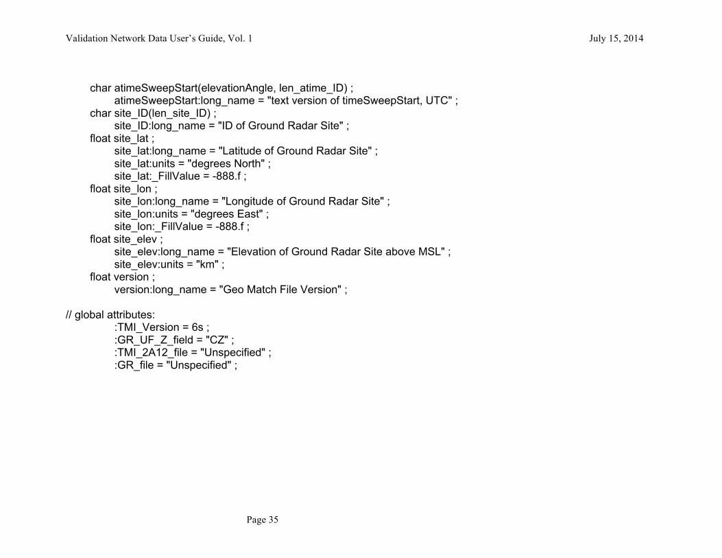
char atimeSweepStart(elevationAngle, len_atime_ID) ; atimeSweepStart:long_name = "text version of timeSweepStart, UTC" ; char site_ID(len_site_ID) ; site_ID:long_name = "ID of Ground Radar Site" ; float site_lat ; site_lat:long_name = "Latitude of Ground Radar Site" ; site_lat:units = "degrees North" ; site_lat:_FillValue = -888.f ; float site_lon ; site_lon:long_name = "Longitude of Ground Radar Site" ; site_lon:units = "degrees East" ; site_lon:_FillValue = -888.f ; float site_elev ; site_elev:long_name = "Elevation of Ground Radar Site above MSL" ; site_elev:units = "km" ; float version ; version:long_name = "Geo Match File Version" ; // global attributes: :TMI_Version = 6s ; :GR_UF_Z_field = "CZ" ; :TMI_2A12_file = "Unspecified" ; :GR_file = "Unspecified" ;
Validation Network Data User’s Guide, Vol. 1 July 15, 2014
Page 36
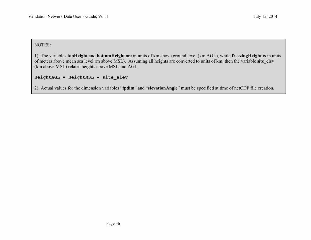
NOTES: 1) The variables topHeight and bottomHeight are in units of km above ground level (km AGL), while freezingHeight is in units of meters above mean sea level (m above MSL). Assuming all heights are converted to units of km, then the variable site_elev (km above MSL) relates heights above MSL and AGL: HeightAGL = HeightMSL - site_elev 2) Actual values for the dimension variables “fpdim” and “elevationAngle” must be specified at time of netCDF file creation.
Validation Network Data User’s Guide, Vol. 1 July 15, 2014
Page 37
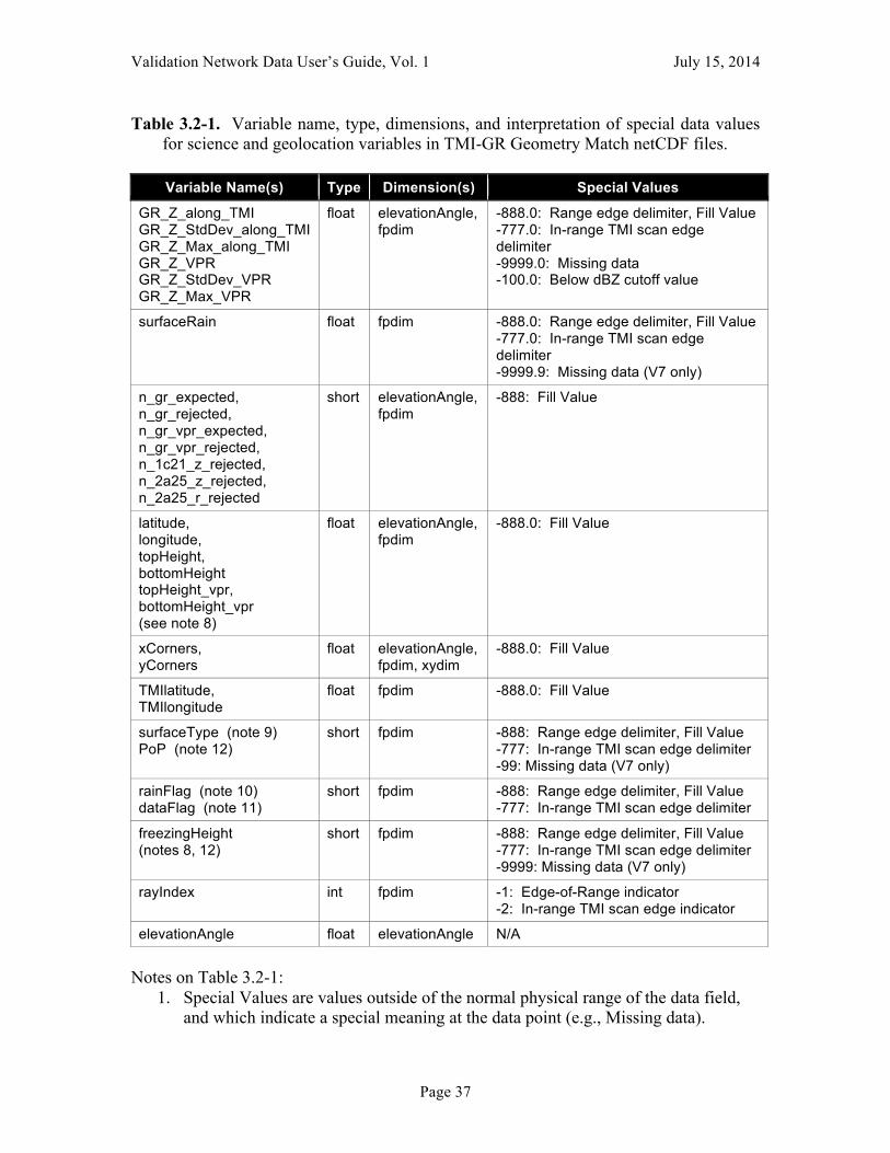
Table 3.2-1. Variable name, type, dimensions, and interpretation of special data values for science and geolocation variables in TMI-GR Geometry Match netCDF files.
Variable Name(s) Type Dimension(s) Special Values
GR_Z_along_TMI GR_Z_StdDev_along_TMI GR_Z_Max_along_TMI GR_Z_VPR GR_Z_StdDev_VPR GR_Z_Max_VPR
float elevationAngle, fpdim
-888.0: Range edge delimiter, Fill Value -777.0: In-range TMI scan edge delimiter -9999.0: Missing data -100.0: Below dBZ cutoff value
surfaceRain float fpdim -888.0: Range edge delimiter, Fill Value -777.0: In-range TMI scan edge delimiter -9999.9: Missing data (V7 only)
n_gr_expected, n_gr_rejected, n_gr_vpr_expected, n_gr_vpr_rejected, n_1c21_z_rejected, n_2a25_z_rejected, n_2a25_r_rejected
short elevationAngle, fpdim
-888: Fill Value
latitude, longitude, topHeight, bottomHeight topHeight_vpr, bottomHeight_vpr (see note 8)
float elevationAngle, fpdim
-888.0: Fill Value
xCorners, yCorners
float elevationAngle, fpdim, xydim
-888.0: Fill Value
TMIlatitude, TMIlongitude
float fpdim -888.0: Fill Value
surfaceType (note 9) PoP (note 12)
short fpdim -888: Range edge delimiter, Fill Value -777: In-range TMI scan edge delimiter -99: Missing data (V7 only)
rainFlag (note 10) dataFlag (note 11)
short fpdim -888: Range edge delimiter, Fill Value -777: In-range TMI scan edge delimiter
freezingHeight (notes 8, 12)
short fpdim -888: Range edge delimiter, Fill Value -777: In-range TMI scan edge delimiter -9999: Missing data (V7 only)
rayIndex int fpdim -1: Edge-of-Range indicator -2: In-range TMI scan edge indicator
elevationAngle float elevationAngle N/A
Notes on Table 3.2-1:
1. Special Values are values outside of the normal physical range of the data field, and which indicate a special meaning at the data point (e.g., Missing data).

Validation Network Data User’s Guide, Vol. 1 July 15, 2014
Page 38
2. Range edge points are the nearest TMI footprints outside of, but immediately adjacent to, the range ring surrounding the ground radar at distance = rangeThreshold, for a given TMI scan. These points form a partial circle around points for the TMI footprints within the rangeThreshold of the ground radar, the latter which contain actual data values.
3. In-range TMI scan edge points are the single TMI footprints of PR extrapolated just beyond either edge of the TMI scan, and which fall within or immediately adjacent to the rangeThreshold distance from the ground radar.
4. The combination of the Range Edge points and the Scan Edge points serve to completely enclose the in-range TMI footprints on the surface: a) defined by each elevation sweep (for multi-level variables), or b) at the earth surface (for single level variables). The purpose of these points is to prevent the extrapolation of “actual” TMI data values outside of the in-range area, if the data are later analyzed to a regular grid using an objective analysis technique.
5. Range Edge points and Scan Edge points are indicated by rayIndex values of -1 and -2, respectively. rayIndex values of 0 or greater are actual 1-D equivalent array indices of TMI footprints within the full data arrays in the 2A-12 data files.
6. Range and Scan Edge points are optional and, as a default, are disabled from being computed and output. If the “Mark Edges” parameter’s default value is overridden, then these types of points will then be computed and output as described above.
7. Fill Value is the value to which scalar or array variables in the netCDF file are initialized when the file is created. These values remain in place unless and until the data value is overwritten.
8. The variables topHeight and bottomHeight represent height above ground level (AGL) (i.e., height above the ground radar) in km, while freezingHeight represents height above mean sea level (MSL; the earth ellipsoid, actually), in meters. The difference between AGL height and MSL height is given by the value of the site_elev variable, the height above MSL of the ground radar, in km. To compare freezingHeight to topHeight or bottomHeight, first convert freezingHeight to km units. Then, either subtract site_elev from freezingHeight to work in AGL height units, or add site_elev to topHeight and bottomHeight to work in MSL height units.
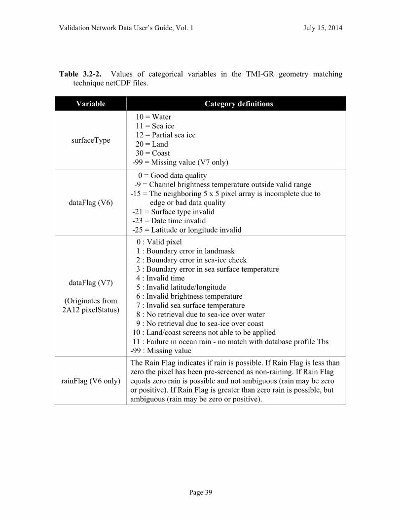
9. The surfaceType variable originates from the surfaceFlag variable in the TRMM Version 6 2A-12 product, and from the surfaceType variable in version 7. Version 6 surfaceFlag values are mapped to the corresponding Version 7 surfaceType. Refer to Table 3.2-2.
10. The rainFlag variable is not available in the Version 7 2A-12 data, so its values are all Fill Value in V7 matchup data.
11. The dataFlag variable originates from the dataFlag variable in the TRMM Version 6 2A-12 product, and from the pixelStatus variable in version 7. Values for each version are as defined in Table 3.2-2.
12. The PoP (2A-12 probabilityOfPrecipitation) and freezingHeight variables are not available in the Version 6 2A-12 data, so its values are all Fill Value in V6 matchup data. PoP values are assigned only for TMI footprints with surfaceType “water”, and are undefined (-99) over land and coast.
Validation Network Data User’s Guide, Vol. 1 July 15, 2014
Page 39
Table 3.2-2. Values of categorical variables in the TMI-GR geometry matching technique netCDF files.
Variable Category definitions
surfaceType
10 = Water 11 = Sea ice 12 = Partial sea ice 20 = Land 30 = Coast
-99 = Missing value (V7 only)
dataFlag (V6)
0 = Good data quality -9 = Channel brightness temperature outside valid range -15 = The neighboring 5 x 5 pixel array is incomplete due to edge or bad data quality -21 = Surface type invalid -23 = Date time invalid -25 = Latitude or longitude invalid
dataFlag (V7)
(Originates from 2A12 pixelStatus)
0 : Valid pixel 1 : Boundary error in landmask 2 : Boundary error in sea-ice check 3 : Boundary error in sea surface temperature 4 : Invalid time 5 : Invalid latitude/longitude 6 : Invalid brightness temperature 7 : Invalid sea surface temperature 8 : No retrieval due to sea-ice over water 9 : No retrieval due to sea-ice over coast 10 : Land/coast screens not able to be applied 11 : Failure in ocean rain - no match with database profile Tbs -99 : Missing value
rainFlag (V6 only)
The Rain Flag indicates if rain is possible. If Rain Flag is less than zero the pixel has been pre-screened as non-raining. If Rain Flag equals zero rain is possible and not ambiguous (rain may be zero or positive). If Rain Flag is greater than zero rain is possible, but ambiguous (rain may be zero or positive).

Validation Network Data User’s Guide, Vol. 1 July 15, 2014
Page 40
4. Directory Structure of the VN ftp site
This section describes the directory structure for the VN data ftp site:
ftp://hector.gsfc.nasa.gov/gpm-validation/data/gpmgv
In the directory structures shown below, all directory and filename values and/or fields indicated in regular text are literal fields that never vary from those shown. The fields shown in bold italics vary according to the value of the field code they represent. Fields enclosed in [brackets] are optional, and the brackets are not part of the file names. The field codes are defined in Table 4-1. /coincidence_table/ (Note-1) CT.YYMMDD.V CT.YYMMDD.unl CTYYMMarchive.tar.gz /db_backup/ (Note-2) gpmgvDBdump.gz gpmgvDBdump.old.gz /gv_radar (Note-3) /defaultQC_in /xxxx /1C51 /YYYY /MMDD/ 1C51.YYMMDD.N.TTTT.V.HDF.gz /1CUF /YYYY /MMDD/ YYMMDD.N.TTTT.V.hhmm.uf.gz (Note-7) XXXX_YYYY_MMDD_hhmmss.uf.gz (Note-7) /images /YYYY /MMDD/ TTTT_FF_YYMMDD.hhmm.q1q2q3.q4q5q6q7.ee.gif /raw /YYYY /MMDD/ XXXXYYYYMMDD_hhmmss.gz /finalQC_in (Note-3) /xxxx /1C51 /YYYY /MMDD/ 1C51.YYMMDD.N.TTTT.V.HDF.gz

Validation Network Data User’s Guide, Vol. 1 July 15, 2014
Page 41
/1CUF /YYYY /MMDD/ YYMMDD.N.TTTT.V.hhmm.uf.gz (Note-7) XXXX_YYYY_MMDD_hhmmss.uf.gz (Note-7) /images /YYYY /MMDD/ TTTT_FF_YYMMDD.hhmm.q1q2q3.q4q5q6q7.ee.gif /level_2 /YYYY /gvs_2A-5G-dc_XXXX_MM_YYYY/ 2A5G.YYMMDD.N.TTTT.V.HDF.gz /mosaicimages (Note-4) /archivedmosaic/ YYYY-MM-DD_hhmm.gif /netcdf (Note-5) /geomatch/ GRtoPR.XXXX.YYMMDD.#####.nc.gz GRtoTMI.XXXX.YYMMDD.#####.nc.gz /prsubsets (Note-6, Note-8) /1C21/ 1C21_CSI.[YY]YYMMDD.#####.SSSS.V.HDF.Z 1C21_GPM_KMA.YYMMDD.#####.SSSS.V.HDF.gz 1C21.YYYYMMDD.#####.SSSS.V. GPM_KMA.hdf.gz 1C21. [YY]YYMMDD.#####.V.sub-GPMGV1.hdf.gz 1C21. [YY]YYMMDD.#####.V.HDF.Z /2A12/ 2A12_CSI.[YY]YYMMDD.#####.SSSS.V.HDF.Z 2A12. [YY]YYMMDD.#####.V.sub-GPMGV1.hdf.gz /2A23/ 2A23_CSI. [YY]YYMMDD.#####.SSSS.V.HDF.Z 2A23_GPM_KMA.YYMMDD.#####.SSSS.V.HDF.gz 2A23.YYYYMMDD.#####.SSSS.V. GPM_KMA.hdf.gz 2A23. [YY]YYMMDD.#####.V.sub-GPMGV1.hdf.gz 2A23. [YY]YYMMDD.#####.V.HDF.Z /2A25/ 2A25_CSI. [YY]YYMMDD.#####.SSSS.V.HDF.Z 2A25_GPM_KMA. YYMMDD.#####.SSSS.V.HDF.gz 2A25.YYYYMMDD.#####.SSSS.V. GPM_KMA.hdf.gz 2A25. [YY]YYMMDD.#####.V.sub-GPMGV1.hdf.gz 2A25. [YY]YYMMDD.#####.V.HDF.Z /2B31/

Validation Network Data User’s Guide, Vol. 1 July 15, 2014
Page 42
2B31_CSI. [YY]YYMMDD.#####.SSSS.V.HDF.Z 2B31_GPM_KMA.YYMMDD.#####.SSSS.V.HDF.gz 2B31.YYYYMMDD.#####.SSSS.V. GPM_KMA.hdf.gz 2B31. [YY]YYMMDD.#####.V.sub-GPMGV1.hdf.gz 2B31. [YY]YYMMDD.#####.V.HDF.Z
Table 4-1. Field Definitions for Directory and Filename Conventions Field Code Definition
##### TRMM orbit number, 1 to 5 digits
ee sequential elevation sweep number, zero-based
FF radar field variable: DZ (reflectivity), CZ (post-QC reflectivity), VR (radial velocity)
5G TRMM GV level-2 gridded product subtype: 53 (2A-53), 54 (2A-54), 55 (2A-55)
hhmm 2-digit hour (hh) and minute (mm)
hhmmss 2-digit hour (hh), minute (mm), and second (ss)
MM 2-digit month
MMDD 2-digit month (MM) and day of month (DD)
N nominal hour of data, from rounding up (1-24)
q1 QC Height Threshold: CAPPI height (km), 2-digit w. leading zero (e.g., 02)
q2 QC Height Threshold: Minimum cloud height (km), 2-digit w. leading zero
q3 QC Height Threshold: Max height QC search (km), 2-digit w. leading zero
q4 QC Reflectivity Threshold: Min Zmax @ 1.5 km (dBZ)
q5 QC Reflectivity Threshold: Min Zmax @ 3.0 km (dBZ)
q6 QC Reflectivity Threshold: Min Z @ lowest tilt (dBZ)
q7 QC Reflectivity Threshold: Min Zmax @ q1 height (dBZ)
SSSS TRMM CSI Product Subset ID for products from the DAAC
TTTT TRMM GV 4-letter station ID (see Table 4-3)
V product version number
xxxx lower-case version of XXXX
XXXX NWS (also GPM GV) 4-letter station ID (see Tables 1-1, 4-3)
YYMM 2-digit year (YY) and month (MM)
[YY]YYMMDD 2- or 4-digit year (YY or YYYY), month (MM), and day of month (DD)
YYYY 4-digit year
Note-1. Files in the coincidence_table directory are Daily Coincidence Table (CT) files from the TRMM Precipitation Processing Subsystem (PPS). The tables contain the orbit number, date, time, distance, and direction of the TRMM orbital subtrack’s nearest
Validation Network Data User’s Guide, Vol. 1 July 15, 2014
Page 43
approach to the ground radar sites configured for this purpose in the PPS. The CT cutoff distance is 700 km. Files in the form CT.YYMMDD.V are the complete, original CT files from the PPS. Those with the “.unl” file extension contain CT data reformatted in a form to be loaded in the GPM GV PostgreSQL database, for only the ground radar sites used in the GPM Validation Network. Older daily files are accumulated into monthly tar files (CTYYMMarchive.tar.gz), compressed using gzip.
Note-2. Files in the db_backup directory contain a backup (dump) of the GPM VN’s PostgreSQL database ‘gpmgv’, created using the pg_dump utility, and compressed using gzip. The latest dump of the database is in the file ‘gpmgvDBdump.gz’.55This5file5is5renamed5to5‘gpmgvDBdump.old.gz’5as5each5new5backup5is5performed.55Only5the5current5and5previous5dumps5are5retained.
Note-3. The files in under the top-level gv_radar directory contain ground radar data in multiple file formats. These radar data come mostly from U.S. domestic WSR-88D radars, but data from other ground radars are also located in this directory structure. Files that fall under the high-level directory defaultQC_in are from the KWAJ and WSR-88D radars, and have been subject to the default quality control processes within the TRMM GV. Files from the KWAJ and WSR-88D radars that fall under the higher-level directory finalQC_in are those that were subject to both automated and human quality control.
Ground radar data in both directories (defaultQC_in and finalQC_in) are organized into subdirectories in the following order: (a) station ID, (b) file type, (c) year, and (d) month/day (except for the level_2 file type, where the lowest level directory is file_subtype/month).
Files in the 1C51 subdirectories contain a full volume scan of ground radar data in a Hierarchical Data Format-4 (HDF-4) file conforming to the TRMM 1C51 format and content. Each data file contains data for one ground radar volume scan. Within the individual data file names, the fixed field “HDF” designates that this is a HDF file, and “.gz” designates that this file has been compressed using gzip.
The files in the 1CUF subdirectories contain a full volume scan of ground radar data conforming to the “Universal Format” (UF) data format. Each data file contains data for one ground radar volume scan. Within the individual data file names, the fixed field “uf “ designates that this is a radar file in Universal Format.
Files in the images subdirectories are Plan Position Indicator (PPI) display images of reflectivity and radial velocity from the ground radar, for selected elevation sweeps. Files that fall under the high-level directory defaultQC_in are those that were subject to the default quality control procedures. Files that fall under the higher-level directory finalQC_in are those that were subject to both automated and human quality control. The variable fields q1-q7 in the individual file names document the quality control threshold values applied in the TRMM GV quality control procedures. Within the individual data file names, the fixed field “gif” designates that the image file is in GIF format.

Validation Network Data User’s Guide, Vol. 1 July 15, 2014
Page 44
Files in the raw subdirectory are the original radar data files in their native format, as obtained from the data source. For the WSR-88D sites, the files are in the NEXRAD Level-II archive format, not to be confused with the TRMM GV Level 2 gridded radar products in the level_2 subdirectory. Recent WSR-88D Level-II archive products are degraded from the Build 10 super-resolution format to the legacy Level-II archive format prior to quality control and ingest by the GPM VN prototype. Each data file contains data for one ground radar volume scan.
Files under the level_2 subdirectory are three types of TRMM GV Level 2 gridded radar products: 2A-53, 2A-54, and 2A-55, with each type stored in separate lower-level subdirectories. Individual data files in this directory contain gridded ground radar data for both observed and derived variables, as documented in5Interface)Control)Specification)Between)the)TSDIS)and)the)TSDIS)Science)User)(TSU),)Volume)4;))File)Specifications)for)TRMM)Products)D)Levels)2)and)3.5 The Level 2 products in the VN data set contain data for only one ground radar volume scan. For these products, a lowest-level, product/site/month-specific subdirectory naming convention needs to be described, as follows: /gvs_2A-5G-dc_XXXX_MM_YYYY where: gvs_2A- is fixed text 5G = 2-digit product ID number (53, 54, or 55) -dc is fixed text XXXX = 4-character TRMM GV radar station ID, see Table 4-3 MM = 2-digit month YYYY = 4-digit year
Note-4. Files under the mosaicimages directory are National Weather Service (NWS) WSR-88D national-scale radar mosaic images (RIDGE mosaics). RIDGE national mosaics are produced every 10 minutes by the NWS. Only those mosaics corresponding to the time of TRMM overpasses of the GPM Validation Network PR subset area in the southeastern U.S. are contained in the archivedmosaic subdirectory.
Note-5. The two types of files in the netcdf/geo_match directory structure contain (1) geometrically-matched ground radar and TRMM Precipitation Radar (GRtpPR) data, and (2) geometrically matched ground radar and TRMM Microwave Imager (GRtoTMI) data, in netCDF format as described above in Section 2 of the VN Data User’s Guide. Each file corresponds to single ground radar volume scan taken nearest in time to where a TRMM satellite orbit’s subtrack passes within 200 km of the ground radar during a “significant” rainfall event.
Note-6. The files in the 1C21 directory contain TRMM PR 1C-21 data products in HDF-4 format. Each file corresponds to an either an orbital subset of the TRMM PR data, where the orbital subset falls within a specific geographical “bounding box” that encompasses one or more Validation Network ground radars; or PR data for a full orbit. The file naming convention varies by orbit subset or full orbit, as follows:
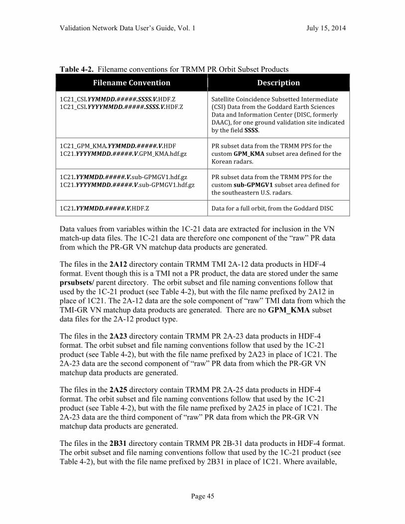
Validation Network Data User’s Guide, Vol. 1 July 15, 2014
Page 45
Table 4-2. Filename conventions for TRMM PR Orbit Subset Products
Filename(Convention( Description(
1C21_CSI.YYMMDD.#####.SSSS.V.HDF.Z51C21_CSI.YYYYMMDD.#####.SSSS.V.HDF.Z5
Satellite5Coincidence5Subsetted5Intermediate5(CSI)5Data5from5the5Goddard5Earth5Sciences5Data5and5Information5Center5(DISC,5formerly5DAAC),5for5one5ground5validation5site5indicated5by5the5field5SSSS.5
1C21_GPM_KMA.YYMMDD.#####.V.HDF51C21.YYYYMMDD.#####.V.GPM_KMA.hdf.gz5
PR5subset5data5from5the5TRMM5PPS5for5the5custom5GPM_KMA5subset5area5defined5for5the5Korean5radars.5
1C21.YYMMDD.#####.V.subSGPMGV1.hdf.gz51C21.YYYYMMDD.#####.V.subSGPMGV1.hdf.gz5
PR5subset5data5from5the5TRMM5PPS5for5the5custom5sub;GPMGV15subset5area5defined5for5the5southeastern5U.S.5radars.5
1C21.YYMMDD.#####.V.HDF.Z5 Data5for5a5full5orbit,5from5the5Goddard5DISC5
Data values from variables within the 1C-21 data are extracted for inclusion in the VN match-up data files. The 1C-21 data are therefore one component of the “raw” PR data from which the PR-GR VN matchup data products are generated.
The files in the 2A12 directory contain TRMM TMI 2A-12 data products in HDF-4 format. Event though this is a TMI not a PR product, the data are stored under the same prsubsets/ parent directory. The orbit subset and file naming conventions follow that used by the 1C-21 product (see Table 4-2), but with the file name prefixed by 2A12 in place of 1C21. The 2A-12 data are the sole component of “raw” TMI data from which the TMI-GR VN matchup data products are generated. There are no GPM_KMA subset data files for the 2A-12 product type.
The files in the 2A23 directory contain TRMM PR 2A-23 data products in HDF-4 format. The orbit subset and file naming conventions follow that used by the 1C-21 product (see Table 4-2), but with the file name prefixed by 2A23 in place of 1C21. The 2A-23 data are the second component of “raw” PR data from which the PR-GR VN matchup data products are generated.
The files in the 2A25 directory contain TRMM PR 2A-25 data products in HDF-4 format. The orbit subset and file naming conventions follow that used by the 1C-21 product (see Table 4-2), but with the file name prefixed by 2A25 in place of 1C21. The 2A-23 data are the third component of “raw” PR data from which the PR-GR VN matchup data products are generated.
The files in the 2B31 directory contain TRMM PR 2B-31 data products in HDF-4 format. The orbit subset and file naming conventions follow that used by the 1C-21 product (see Table 4-2), but with the file name prefixed by 2B31 in place of 1C21. Where available,
Validation Network Data User’s Guide, Vol. 1 July 15, 2014
Page 46
the 2B-31 data are the fourth component of “raw” PR data from which the PR-GR VN matchup data products are generated, but are optional to the matchup processing.
Note that the datestamp convention changed from YYMMDD to YYYYMMDD from Version 6 to Version 7 files.
Note-7. The filename convention for the 1CUF files changed beginning with the inclusion of dual-polarimetric variables in the data files. Prior to the dual-pol upgrade, the name convention followed the YYMMDD.N.TTTT.V.hhmm.uf.gz pattern. After the upgrade and once TRMM GV began to include the dual-polarization data variables in the files, the name convention changes to the XXXX_YYYY_MMDD_hhmmss.uf.gz pattern. The dual-polarization file names include the NWS site identifiers (XXXX field) in the 1CUF file names and directory trees, such that the TRMM GV site IDs for the WSR-88D sites (Table 4-3) are no longer used in the 1CUF file names. The date of the changeover to dual-polarization data files differs by site.
Note-8. The data structure under the prsubsets directory applies to TRMM data ingested by the GPM Validation Network prior to the launch of GPM. A new data structure and file naming convention for TRMM data has been put into place for data beginning in March 2014. See Section 4 of the Validation Network Data Product User’s Guide, Volume 2 - GPM Data Products for a description of this directory structure.
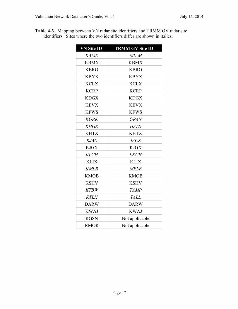
Validation Network Data User’s Guide, Vol. 1 July 15, 2014
Page 47
Table 4-3. Mapping between VN radar site identifiers and TRMM GV radar site identifiers. Sites where the two identifiers differ are shown in italics.
VN Site ID TRMM GV Site ID
KAMX MIAM KBMX KBMX KBRO KBRO KBYX KBYX KCLX KCLX KCRP KCRP KDGX KDGX KEVX KEVX KFWS KFWS KGRK GRAN KHGX HSTN KHTX KHTX KJAX JACK KJGX KJGX KLCH LKCH KLIX KLIX KMLB MELB KMOB KMOB KSHV KSHV KTBW TAMP KTLH TALL
DARW DARW KWAJ KWAJ RGSN Not applicable RMOR Not applicable

Validation Network Data User’s Guide, Vol. 1 July 15, 2014
Page 48
5. Geometry Matching Algorithm Descriptions The following sections provide a high-level schematic of the PR-GR and TMI-GR geometry matching algorithms. Detailed documentation of the algorithms is contained in the source code.
5.1 PR match-up sampling to GR The basic PR-to-GR data processing algorithm is as follows:
1. For each PR ray in the product, compute the range of the ray's earth intersection point from the ground radar location. If greater than 100 km (adjustable), ignore the ray. If within 100 km, proceed as follows:
2. Examine the corrected reflectivity values along the PR ray. If one or more gates are at or above a specified threshold (18 dBZ), proceed with processing the ray, otherwise set the PR and GR match-up values to “below threshold” and proceed to the next PR ray.
3. Using the range from step 1, determine the height above ground level where the PR ray intersects the centerline of each of the elevation sweeps of the GR, and the width (as a vertical distance) of the GR beam at this range;
4. Compute a parallax-adjusted location of the PR footprint center at each GR sweep intersection height from step 3, as a function of height, the PR ray angle relative to nadir, and the orientation (azimuth) of the PR scan line. Retain these adjusted horizontal locations for the processing of the GR data;
5. Using the beam heights and widths from step 3, compute the upper and lower bound heights of each GR sweep at its intersection with the PR ray, correcting for height above MSL (the earth ellipsoid) as required for the PR height definition;
6. For each GR sweep intersection, determine the total number, and along-ray positions, of the PR range gates located between the upper and lower bound heights from step 5;
7. For the PR 3-D fields, perform a simple average of values over the set of range gates identified in step 6, for each GR sweep intersection (Figure 2-2). Reflectivity is converted from dBZ to Z before averaging, then the average Z is converted back to dBZ. Only those gates with values at or above specified reflectivity (18 dBZ) or rain rate (0.01 mm h-1) thresholds are included in the average. Keep track of the number of below-threshold PR gates rejected from the vertical averages, and the number of gates expected in the averages from a geometric standpoint (from step 6);
8. For the 2-D PR field values (e.g., surface rain rate, bright band height), simply extract or derive the scalar field value for the given PR ray.
9. Using the parallax-adjusted locations of the PR footprints from step 4, compute the four x- and y-corners of the PR footprint, which can be used to plot the PR data on a map or image in a contiguous, non-overlapping manner. Each corner point is computed as the midway point between the PR footprint center x,y coordinates and those of the four diagonally-adjacent PR footprints (extrapolated
Validation Network Data User’s Guide, Vol. 1 July 15, 2014
Page 49
if at the edge of the PR scan). These corner coordinates do not represent the area of the actual PR measurement in any physical manner.
The 3-D PR fields which are vertically averaged, yielding one value per intersected GR sweep per PR ray, include:
• Raw PR reflectivity (Zr, in dBZ) from TRMM product 1C-21 • Attenuation-Corrected PR reflectivity (Zc, in dBZ) from TRMM product 2A-25 • Rain rate (mm/h) from TRMM product 2A-25.
The 2-D PR variables which are taken unaveraged, one value per PR ray, include:
• Raw PR reflectivity (Zr, in dBZ) from TRMM product 1C-21 • Surface type (land/ocean/coastal) flag • Near-surface rain rate, mm/h • Bright band height • Rain type categorization (convective, stratiform, other) • Rain/no-rain flag.
These scalar values are directly extracted and/or derived from data fields within PR products 1C-21 and 2A-25.
5.2 GR match-up sampling to PR The basic GR-to-PR data processing algorithm is as follows:
1. For each PR ray processed (i.e., not skipped in Step 2, above), and for each elevation sweep of the GR, repeat the following:
2. Compute the along-ground distance between each GR bin center and the parallax-adjusted PR footprint center (from PR step 4);
3. Flag the GR bins within a fixed distance of the PR center. The fixed distance is equivalent to the maximum radial size of all the PR footprints processed. Ignore GR bins above 20 km above ground level
4. Examine the reflectivity values of the flagged GR bins from step 3. If all values fall below 0.0 dBZ, then skip processing for the point and set its match-up value to “below threshold”. Otherwise:
5. Perform an inverse distance weighted average of the GR reflectivity values over the bins from step 4 (Figure 2-3), using a Barnes gaussian weighting. Reflectivity is converted from dBZ to Z before averaging, then the average Z is converted back to dBZ. All GR bins with values at or above 0.0 dBZ are included in the average. Keep track of the total number of bins included in the average, and the number of these GR bins with values meeting a specified reflectivity threshold (15 dBZ).
Validation Network Data User’s Guide, Vol. 1 July 15, 2014
Page 50
5.3 TMI match-up sampling The only computations that take place on the TMI data are to determine which TMI footprints are within a given range threshold of the GR site, and for each in-range TMI footprint, to compute the intersection of the TMI instrument field-of-view with each of the GR sweeps. The basic TMI-to-GR data processing algorithm is as follows:
1. For each TMI footprint in the product, compute the range of the footprint's earth intersection point from the ground radar location. If greater than 100 km (adjustable), ignore the ray. If within 100 km, proceed as follows:
2. Compute the azimuth between the TMI footprint and the TRMM satellite’s nadir subpoint. This gives the earth-relative direction along which the TMI is viewing.
3. Using the range and azimuth from steps 1 and 2, and the fixed TMI scan incidence angle relative to the ground, determine the height above ground level where the TMI view centerline intersects the centerline of each of the elevation sweeps of the GR, and the width (as a vertical distance) of the GR beam at this range;
4. Compute a parallax-adjusted location of the TMI footprint center at each GR sweep intersection height from step 3, as a function of height, the TMI incidence angle, and the orientation (azimuth) of the TMI scan line. Retain these adjusted horizontal locations for the processing of the GR data;
5. Using the beam heights and widths from step 3, compute the upper and lower bound heights of each GR sweep at its intersection with the TMI scan sample;
6. Taking the TMI footprint’s surface position, and ignoring TMI viewing parallax, project the TMI footprint along the local vertical to the earth surface and determine the height above ground level where local vertical intersects the centerline of each of the elevation sweeps of the GR, and the width (as a vertical distance) of the GR beam at this range. Retain the unadjusted surface footprint locations for the processing of the GR data;
7. Using the beam heights and widths from step 6, compute the upper and lower bound heights of each GR sweep at its intersection with the local vertical above the TMI surface footprint;
8. For the 2-D TMI field values (e.g., surface rain rate), simply extract the scalar field value for each in-range TMI footprint.
9. Using the parallax-adjusted locations of the TMI footprints from step 4, compute the four x- and y-corners of the TMI footprint, which can be used to plot the TMI data on a map or image in a contiguous, non-overlapping manner. Each corner point is computed as the midway point between the TMI footprint center x,y coordinates and those of the four diagonally-adjacent TMI footprints (extrapolated if at the edge of the TMI scan). These corner coordinates do not represent the area of the actual TMI measurement in any physical manner.

Validation Network Data User’s Guide, Vol. 1 July 15, 2014
Page 51
The TMI 2A-12 variables which are included in the matchups, one value per footprint, include:
• Surface rain rate, mm/h • TMI latitude (surface footprint center position) • TMI longitude (ditto) • Surface type (land/ocean/coast) • Rain flag (V6 only) • Data flag • Probability of Precipitation (PoP; V7 only) • Freezing height (V7 only).
These scalar values are directly extracted from data fields within the TMI 2A-12 product.
5.4 GR match-up sampling to TMI The GR-to-TMI algorithm is nearly identical to the GR-to-PR algorithm, except for TMI we compute two sets of GR matchup samples, one along the sloping TMI instrument scan line-of-sight (Fig. 5.4-1), and one along the local vertical above the TMI surface footprint position (Fig. 5.4-2). The basic GR-to-TMI data processing algorithm is as follows:
1. For each in-range TMI footprint processed, and for each elevation sweep of the GR, repeat the following:
2. Compute the along-ground distance between each GR bin center and the parallax-adjusted TMI footprint center (from TMI step 4);
3. Flag the GR bins within a fixed distance of the TMI footprint center (Figure 5.4-1). The fixed distance is equivalent to the spacing between adjacent TMI surface footprints along a diagonal. Ignore GR bins above 20 km above ground level.
4. Examine the reflectivity values of the flagged GR bins from step 3. If all values fall below a 0.0 dBZ threshold, then skip processing for the point and set its match-up value to “below threshold”. Otherwise:
5. Perform an inverse distance weighted average of the GR reflectivity values over the bins from step 4, using a Barnes gaussian weighting. Reflectivity is converted from dBZ to Z before averaging, then the average Z is converted back to dBZ. All GR bins with values at or above 0.0 dBZ are included in the average. Keep track of the total number of bins included in the average, and the number of these GR bins with values meeting a specified reflectivity threshold (15 dBZ by default).
6. Repeat step 2, but for the unadjusted TMI footprint center (along the local vertical, from TMI step 6).
7. Repeat step 3 for the TMI footprint center in step 6, as shown in Fig. 5.4-2. 8. Repeat steps 4 and 5 for the GR bins flagged in step 7.
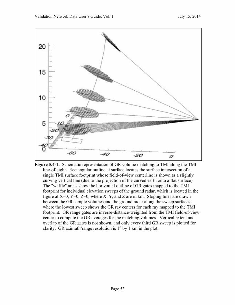
Validation Network Data User’s Guide, Vol. 1 July 15, 2014
Page 52
Figure 5.4-1. Schematic representation of GR volume matching to TMI along the TMI
line-of-sight. Rectangular outline at surface locates the surface intersection of a single TMI surface footprint whose field-of-view centerline is shown as a slightly curving vertical line (due to the projection of the curved earth onto a flat surface). The "waffle" areas show the horizontal outline of GR gates mapped to the TMI footprint for individual elevation sweeps of the ground radar, which is located in the figure at X=0, Y=0, Z=0, where X, Y, and Z are in km. Sloping lines are drawn between the GR sample volumes and the ground radar along the sweep surfaces, where the lowest sweep shows the GR ray centers for each ray mapped to the TMI footprint. GR range gates are inverse-distance-weighted from the TMI field-of-view center to compute the GR averages for the matching volumes. Vertical extent and overlap of the GR gates is not shown, and only every third GR sweep is plotted for clarity. GR azimuth/range resolution is 1° by 1 km in the plot.

Validation Network Data User’s Guide, Vol. 1 July 15, 2014
Page 53
Figure 5.4-2. As in Figure 5.4-1, except GR averaging is along the local vertical above
the TMI surface footprint center rather than along the TMI instrument line-of-sight.
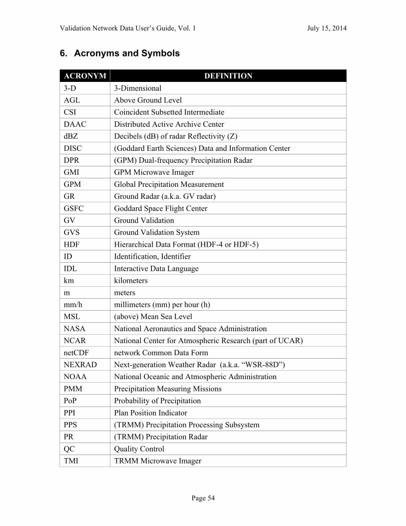
Validation Network Data User’s Guide, Vol. 1 July 15, 2014
Page 54
6. Acronyms and Symbols
ACRONYM DEFINITION 3-D 3-Dimensional AGL Above Ground Level CSI Coincident Subsetted Intermediate DAAC Distributed Active Archive Center dBZ Decibels (dB) of radar Reflectivity (Z) DISC (Goddard Earth Sciences) Data and Information Center DPR (GPM) Dual-frequency Precipitation Radar GMI GPM Microwave Imager GPM Global Precipitation Measurement GR Ground Radar (a.k.a. GV radar) GSFC Goddard Space Flight Center GV Ground Validation GVS Ground Validation System HDF Hierarchical Data Format (HDF-4 or HDF-5) ID Identification, Identifier IDL Interactive Data Language km kilometers m meters mm/h millimeters (mm) per hour (h) MSL (above) Mean Sea Level NASA National Aeronautics and Space Administration NCAR National Center for Atmospheric Research (part of UCAR) netCDF network Common Data Form NEXRAD Next-generation Weather Radar (a.k.a. “WSR-88D”) NOAA National Oceanic and Atmospheric Administration PMM Precipitation Measuring Missions PoP Probability of Precipitation PPI Plan Position Indicator PPS (TRMM) Precipitation Processing Subsystem PR (TRMM) Precipitation Radar QC Quality Control TMI TRMM Microwave Imager

Validation Network Data User’s Guide, Vol. 1 July 15, 2014
Page 55
ACRONYM DEFINITION TRMM Tropical Rainfall Measuring Mission UCAR University Corporation for Atmospheric Research UF Universal Format US United States UTC Coordinated Universal Time VN Validation Network WSR-88D Weather Surveillance Radar - 1988 Doppler (a.k.a. “NEXRAD”)
Validation Network Data User’s Guide, Vol. 1 July 15, 2014
Page 56
7. Appendix
Extended Abstract
SENSITIVITY OF SPACEBORNE AND GROUND RADAR COMPARISON RESULTS TO DATA ANALYSIS METHODS AND CONSTRAINTS
K. Robert Morris and Mathew R. Schwaller
Proceedings of 35th Conference on Radar Meterorology
of the American Meteorological Society
September 26-30, 2011 Pittsburgh, Pennsylvania
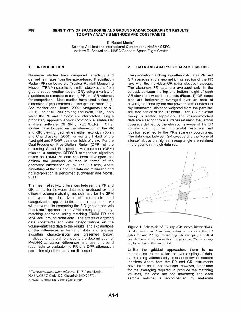
A1-1 !
P68 SENSITIVITY OF SPACEBORNE AND GROUND RADAR COMPARISON RESULTS TO DATA ANALYSIS METHODS AND CONSTRAINTS
K. Robert Morris* Science Applications International Corporation / NASA / GSFC Mathew R. Schwaller -- NASA Goddard Space Flight Center
1. INTRODUCTION Numerous studies have compared reflectivity and derived rain rates from the space-based Precipitation Radar (PR) on board the Tropical Rainfall Measuring Mission (TRMM) satellite to similar observations from ground-based weather radars (GR), using a variety of algorithms to compute matching PR and GR volumes for comparison. Most studies have used a fixed 3-dimensional grid centered on the ground radar (e.g., Schumacher and Houze, 2000; Anagnostou et al., 2001; Liao et al., 2001; Wang and Wolff, 2009), onto which the PR and GR data are interpolated using a proprietary approach and/or commonly available GR analysis software (SPRINT, REORDER). Other studies have focused on the intersection of the PR and GR viewing geometries either explicitly (Bolen and Chandrasekar, 2000), or using a hybrid of the fixed grid and PR/GR common fields of view. For the Dual-Frequency Precipitation Radar (DPR) of the upcoming Global Precipitation Measurement (GPM) mission, a prototype DPR/GR comparison algorithm based on TRMM PR data has been developed that defines the common volumes in terms of the geometric intersection of PR and GR rays, where smoothing of the PR and GR data are minimized and no interpolation is performed (Schwaller and Morris, 2011). The mean reflectivity differences between the PR and GR can differ between data sets produced by the different volume matching methods; and for the GPM prototype, by the type of constraints and categorization applied to the data. In this paper, we will show results comparing the 3-D gridded analysis “black box” approach to the GPM prototype geometry-matching approach, using matching TRMM PR and WSR-88D ground radar data. The effects of applying data constraints and data categorizations on the volume-matched data to the results, and explanations of the differences in terms of data and analysis algorithm characteristics are presented below. Implications of the differences to the determination of PR/DPR calibration differences and use of ground radar data to evaluate the PR and DPR attenuation correction algorithms are also discussed.
*Corresponding author address: K. Robert Morris, NASA/GSFC Code 422, Greenbelt MD 20771. E-mail: [email protected]
2. DATA AND ANALYSIS CHARACTERISTICS The geometry matching algorithm calculates PR and GR averages at the geometric intersection of the PR rays with the individual GR radar elevation sweeps. The along-ray PR data are averaged only in the vertical, between the top and bottom height of each GR elevation sweep it intersects (Figure 1). GR range bins are horizontally averaged over an area of coverage defined by the half-power points of each PR ray intersected, distance-weighted from the parallax-adjusted center of the PR beam. Each GR elevation sweep is treated separately. The volume-matched data are a set of conical surfaces retaining the vertical coverage defined by the elevation sweeps of the GR volume scan, but with horizontal resolution and location redefined by the PR’s scan/ray coordinates. The data gaps between GR sweeps and the “cone of silence” above the highest sweep angle are retained in the geometry-match data set.
Figure 1. Schematic of PR ray /GR sweep intersections. Shaded areas are “matching volumes” showing the PR gates for one PR ray intersecting GR sweeps (dashed) at two different elevation angles. PR gates are 250 m along-ray by ~5 km in the horizontal.
Unlike the gridded approaches there is no interpolation, extrapolation, or oversampling of data, so matching volumes only exist at somewhat random locations where both the PR and GR instruments have taken actual observations. However, other than for the averaging required to produce the matching volumes, the data are not smoothed; and each sample volume is accompanied by metadata
A1-2 !
describing the variability and maximum of the reflectivity within the sample volume, and the fraction of range gates in the PR and GR sample averages having reflectivity values above an adjustable detection threshold (typically taken to be 18 dBZ for the PR). Sample volumes are further characterized by rain type (Stratiform or Convective), proximity to the melting layer, underlying surface (land/water/mixed), and the time difference between the PR and GR observations. The approaches using analysis of PR and GR data to a fixed 3-dimensional grid centered on the GR treat the PR and GR data separately. While offering the simplicity of a regular coordinate system of fixed location and size, grids represent the scan pattern of neither instrument and thus require some amount of smoothing, interpolation, and extrapolation to attempt to fill as many grid points as possible with data values and fill reasonable gaps in the GR volume scan. All resulting non-missing data points are treated equally, whether or not one or both instruments made observations in the volume represented by the grid box. In this study, we consider matched PR and GR reflectivity data from the grid-based volume matching algorithm and the geometry-match algorithm. PR data are from the TRMM 2A-25 attenuation-corrected reflectivity product, Version 6. GR data originate from the WSR-88D Level II Archive reflectivity product, which has been quality-controlled to remove non-precipitating echoes (Wolff et al, 2005). Only data samples within 100 km of the ground radar and the overlap of the PR data swath are evaluated. The 3-D grids used are of 4-km horizontal resolution and 1.5-km vertical resolution, with 13 levels centered between 1.5 and 19.5 km height above the GR. PR data are analyzed to the grid following the methods applied by Liao, et al. (2001). Two different grid analysis methods are applied to the GR data. The first method takes the 2-km-resolution 2A-55 standard TRMM GV product and reduces it to 4 km resolution, as in Liao, et al. (2001). The second method analyzes the Level-II data to the 4-km, 13-level grid using the REORDER radar analysis software. For purposes of comparison to the gridded data, the geometry-match data are grouped into the same 13 vertical levels based on the midpoint height of each sample volume. A mean bright band height is computed for each coincident PR/GR rain case from information provided by the PR bright band detection algorithm, in order to subdivide the data by proximity to the bright band (above, within, or below). In computing the mean reflectivity differences between the PR and GR, the matched volumes are subdivided into categories based on combinations of the following attributes common to both the grid-based and geometry-match data sets:
• TRMM orbit number (defines date and time of the event)
• GR site identifier • height layer (13 layers, 1.5-19.5 km) • proximity to bright band: above, within, or below • rain type: stratiform, convective, or unknown • distance from the GR (0-50, 51-100 km) For each of the data categories defined by the permutations of these attributes, the mean difference between, and standard deviation of, the PR and GR reflectivity for the non-missing sample volumes in the category is computed separately for the grid data and the geometry match data and stored in a data table, along with the identifying attributes and the number of data samples included in the category. Geometry-match data are subdivided by an additional attribute defined as the fraction of the sample with reflectivity above a minimum instrument detection threshold, defined as 18 dBZ for PR and 15 dBZ for the GR (to match the PR detection threshold but allow for a 3 dBZ calibration difference). The geometry matching algorithm determines, from a pure geometric standpoint, the locations of the PR and GR range bins that are "coincident", and the number of each (number PR expected, number GV expected). Then the reflectivity values of each range gate are evaluated before averaging. The number of PR bins below the 18 dBZ threshold (number PR rejected) and the number of GR bins below 15 dBZ (number GV rejected) are computed and related to each PR and GR sample volume. To compute the PR volume average, the algorithm leaves out those range bins below 18 dBZ and averages the remaining (the same approach is taken in determining the vertically-averaged PR reflectivity for a fixed layer in the grid-based algorithm). No range bins are left out in computing the reflectivity average, maximum, and standard deviation for the GR sample volumes, but those bins below 0.0 dBZ are set to 0.0 dBZ. From these attributes, a percentage of each sample volume that is above its respective detection threshold is computed for the geometry-match PR and GR. Samples where both the PR and GR percent-above-threshold is non-zero includes all data points with a non-missing reflectivity value, and is akin to the grid-based approach. Restricting the data to samples with a PR and GR percent-above-threshold constraint of 100% provides the best and fairest comparison between the PR and GR instruments, where the entire PR sample volume is above the PR detection threshold, and the entire GR sample volume is filled with echoes above the PR detection threshold. One of the major goals of this study is to show the effects of varying the percent above threshold criteria on the PR-GR mean reflectivity differences. This study computed mean differences from the geometry-matched data for 11 categories of percent-above-threshold cutoff, ranging between 0 and 100%, by 10% steps.
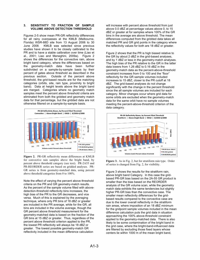
A1-3 !
3. SENSITIVITY TO FRACTION OF SAMPLE VOLUME ABOVE DETECTION THRESHOLD
Figures 2-5 show mean PR-GR reflectivity differences for all rainy overpasses at the KMLB (Melbourne, Florida) WSR-88D site from 13 August 2006 to 30 June 2008. KMLB was selected since previous studies have shown it to be closely calibrated to the PR and to have a stable calibration over time (Liao et al., 2001; Liao and Meneghini, 2009a). Figure 2 shows the differences for the convective rain, above bright band category, where the differences based on the geometry-match data have been further subdivided on a sample-by-sample basis by their percent of gates above threshold as described in the previous section. Outside of the percent above threshold, the grid-based results are for the matching categories (orbits, site, rain type, proximity to bright band). Data at height levels above the bright band are merged. Categories where no geometry match samples meet the percent above threshold criteria are eliminated from both the gridded and geometry match data for that percentage, but the gridded data are not otherwise filtered on a sample-by-sample basis.
Figure 2. PR-GR reflectivity mean differences at KMLB for convective rain samples above the bright band, by percent above threshold category (see text). PR-2A55 and PR-REORDER series are based on gridded analyses. PR-GR series is from geometry-matched data, using percent above threshold categories from 0 to 100%.
Note the effect of varying the percent above threshold criteria on the PR and GR geometry-match results. As the percent of the sample volume filled with above-detection-threshold reflectivity bins increases, the high bias of the PR to the GR decreases, and vice versa. Much of this is explained by the averaging technique, where only PR bins of 18 dBZ or greater are included in the PR average, while for the GR, all bins are included in the volume average, though the GR percent above threshold measurement for the geometry-matched data is based on the fraction of the GR bins at 15 dBZ or greater. Thus, regardless of the percent above threshold criterion applied to the PR, the lowest PR reflectivity will always be 18 dBZ or greater. The lowest possible geometry-match GR reflectivity included in the mean difference calculation
will increase with percent above threshold from just above 0.0 dBZ at percentage values above 0, to 15 dBZ or greater at for samples where 100% of the GR bins in the average are above threshold. The mean differences computed from the gridded data takes all matched PR and GR grid points in the category where the reflectivity values for both are 18 dBZ or greater.
Figure 2 shows that the PR is high biased relative to the GR by about 2 dBZ in the grid-based analyses, and by 1 dBZ or less in the geometry-match analyses. The high bias of the PR relative to the GR in the latter data lowers from 1.26 dBZ to 0.16 dBZ in the geometry-match data as the percent-above-threshold constraint increases from 0 to 100 and the “floor” reflectivity for the GR sample volumes included increases to 15 dBZ, closer to the PR cutoff at 18 dBZ. The grid-based analyses do not change significantly with the change in the percent threshold since the all sample volumes are included for each category. Minor changes occur where grid data for some orbits are excluded when the geometry-match data for the same orbit have no sample volumes meeting the percent-above-threshold criterion of the data category.
Figure 3. As in Fig. 2, but for stratiform rain type. Order of series is changed from Fig. 2, for visibility.
Figure 3 shows the results for the stratiform rain, above bright band Category. In this case the grid-based PR-GR bias based on the 2A-55 GR product is smaller than the bias based on the REORDER analysis of the GR volume scan, while the geometry match data exhibits the same tendencies but slightly higher PR-GR bias than the convective case. The smaller mean reflectivity differences for the grid-based results compared to the convective case are due to the lower overall reflectivity in the stratiform rain areas, where imposition of an 18 dBZ minimum for the gridpoint sample volumes included in the mean difference calculation puts the grid data in situation approaching the 100% above-threshold constraint applied to the geometry-matched data. There is also likely to be some contamination of the bright band in the grid case, where the bright-band-influenced data are filtered by excluding those fixed layers whose centers lie within 1000 m of the mean bright band,

A1-4 !
but, for greater ranges from the radar, the vertical extent of GR bins contributing to such layers may overlap the bright band, raising the GR reflectivity with respect to the PR. The actual top and bottom of each geometry-match sample volume is compared to the mean bright band height when determining whether the sample volume is above, below, or affected by the bright band, so bright band contamination is less likely for these data.
It is this category (stratiform, above bright band) that is used to evaluate calibration differences between the PR and ground radars, as attenuation of the PR at Ku band is at its minimum, and strong horizontal gradients of reflectivity are not present, minimizing the non-uniform beam filling effects. Figure 2 shows that the calibration offset is highly sensitive to the method used to calculate matching PR and GR sample volumes, as well as to the parameters used to select the data samples included in the calculations.
Figures 4 and 5 show the mean differences below the bright band for the convective and stratiform rain rate categories, respectively. The stratiform case in Fig. 5 follows a similar trend to the above-bright-band categories with respect to the change with percent above threshold and the relative biases of the three data sets. The geometry match data for the convective case in Fig. 4 break the pattern of monotonically decreasing PR-GR biases with increasing percent above threshold. In this category, the PR and GR reflectivities change in a similar manner with percent above threshold, perhaps due to the attenuation corrections applied to the PR data.
Figure 4. As in Fig. 2, but for convective samples below the bright band.
The overall high bias of the convective samples for the gridded analyses relative to the geometry match data is due primarily to a few cases of very high convective reflectivities. The mean reflectivity differences are weighted by the number of gridpoints in the category, not case-by-case, so a few cases with high PR-GR biases over large areas are driving up the grid-based biases. The difference between the gridded data and geometry match data in these cases is due to the objective analysis scheme used for the
PR spreading of the high PR reflectivities over a wider area than they are observed, resulting in high PR reflectivities being differenced against lower GR reflectivities. Since the PR data are averaged only in the vertical in the geometry-match analysis, this source of bias is not present in these data.
Figure 5. As in Fig. 2, but for stratiform rain samples below the bright band.
4. SENSITIVITY TO PR-GR TIME DIFFERENCES The time matching rule for PR and GR data selects the GR volume scan with the earliest begin time in a 9-minute window centered on the time of the PR’s closest approach to the GR site. The time offset between the PR and GR data has little effect on the mean reflectivity differences, as the mean PR and GR reflectivities do not change significantly in the range of time offsets resulting from this rule. However, the point-to-point reflectivity differences for fast-moving or evolving precipitation echoes should be expected to increase as the time difference increases. To investigate these differences, the standard deviation of the point-to-point differences was computed for each category, and averaged over the full data set. Figure 6 shows these results for the gridded and geometry-match data sets, for the 100% above-threshold category.
Figure 6. Standard Deviation of PR-KMLB reflectivity differences by time offset between PR and KMLB, for all categories shown in Figs. 2-5, combined.
The standard deviation of the reflectivity differences increases for all 3 data sets as the time difference
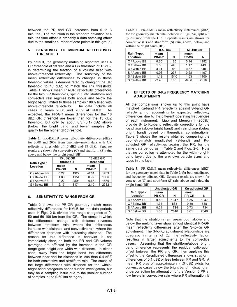
A1-5 !
between the PR and GR increases from 0 to 3 minutes. The reduction in the standard deviation at 4 minutes time offset is probably a data sampling effect due to the smaller number of data points in this group. 5. SENSITIVITY TO MINIMUM REFLECTIVITY
THRESHOLD By default, the geometry matching algorithm uses a PR threshold of 18 dBZ and a GR threshold of 15 dBZ in determining the fraction of a volume filled with above-threshold reflectivity. The sensitivity of the mean reflectivity differences to changes in these threshold values is demonstrated by changing the GR threshold to 18 dBZ, to match the PR threshold. Table 1 shows mean PR-GR reflectivity differences for the two GR thresholds, split out into stratiform and convective rain regimes both above and below the bright band, limited to those samples 100% filled with above-threshold reflectivity. The data include all cases in years 2008 and 2009 at KMLB. As expected, the PR-GR mean differences for the 18 dBZ GR threshold are lower than for the 15 dBZ threshold, but only by about 0.3 (0.1) dBZ above (below) the bright band, and fewer samples (N) qualify for the higher GR threshold. Table 1. PR-KMLB mean reflectivity differences (dBZ) for 2008 and 2009 from geometry-match data with GR reflectivity thresholds of 15 dBZ and 18 dBZ. Separate results are shown for convective (C) and stratiform (S) rain, above and below the bright band (BB).
15 dBZ GR threshold
18 dBZ GR threshold Rain Type /
Location mean PR-GR
N
mean PR-GR
N
C / Above BB 0.27 1922 -0.01 1269 C / Below BB 1.03 1154 0.92 1006 S / Above BB -0.27 2894 -0.63 1566 S / Below BB 2.17 3174 2.10 2382
6. SENSITIVITY TO RANGE FROM GR Table 2 shows the PR-GR geometry match mean reflectivity differences for KMLB for the data periods used in Figs. 2-6, divided into range categories of 0-50 and 50-100 km from the GR. The sense in which the differences change with distance reverses between stratiform rain, where the differences increase with distance, and convective rain, where the differences decrease with increasing distance. The reason for this difference in behavior is not immediately clear, as both the PR and GR volume averages are affected by the increase in the GR range gate height and width with distance. In either case, away from the bright band the difference between near and far distances in less than 0.4 dBZ for both convective and stratiform rain. The cause of the large differences with distance for the within-bright-band categories needs further investigation, but may be a sampling issue due to the smaller number of samples in the 0-50 km category.
Table 2. PR-KMLB mean reflectivity differences (dBZ) for the geometry match data included in Figs. 2-6, split out by distance from the GR. Separate results are shown for convective (C) and stratiform (S) rain, above, below, and within the bright band (BB).
0-50 km 50-100 km Rain Type / Location! mean
PR-GR
N mean
PR-GR
N C / Above BB 0.30 165 0.14 1182 C / Below BB 1.55 445 1.17 443 C / Within BB 3.04 85 0.37 840 S / Above BB -0.03 237 0.28 1497 S / Below BB 1.19 1540 1.53 1100 S / Within BB -2.40 105 -0.66 2818
7. EFFECTS OF S-Ku FREQUENCY MATCHING
ADJUSTMENTS All the comparisons shown up to this point have matched Ku-band PR reflectivity against S-band GR reflectivity, not accounting for expected reflectivity differences due to the different operating frequencies of each instrument. Liao and Meneghini (2009b) provide S- to Ku-band reflectivity corrections for the ice phase (above bright band) and rain phase (below bright band) based on theoretical considerations. Table 3 shows the results obtained comparing the geometry-match unadjusted (S-band) and Ku-adjusted GR reflectivities against the PR, for the same data period as in Table 2 and Figs. 2-6. Note that no correction is attempted for the within-bright-band layer, due to the unknown particle sizes and types in this layer. Table 3. PR-KMLB mean reflectivity differences (dBZ) for the geometry match data in Table 2, for both unadjusted and frequency-adjusted GR. Separate results are shown for convective (C) and stratiform (S) rain, above and below the bright band (BB).
Unadjusted GR Ku-adjusted GR Rain Type /
Location! mean PR-GR
N
mean PR-GR
N
C / Above BB 0.16 1347 1.35 1347 C / Below BB 1.36 888 -0.30 888 S / Above BB 0.24 1734 0.73 1734 S / Below BB 1.33 2640 0.61 2640
Note that the stratiform rain areas both above and below the melting layer show almost identical PR-GR mean reflectivity differences after the S-to-Ku GR adjustment. The S-to-Ku adjustment relationships are quadratic in terms of Ze, the reflectivity factor, resulting in larger adjustments to the convective cases. Assuming that the stratiform/above bright band difference represents the residual calibration offset between the PR and GR, then applying this offset to the Ku-adjusted differences shows stratiform differences of 0.1 dBZ or less between PR and GR. A mean PR bias of approximately -1.0 dBZ exists for convective cases below the bright band, indicating an undercorrection for attenuation of the Version 6 PR at low levels in convective rain where PR attenuation is
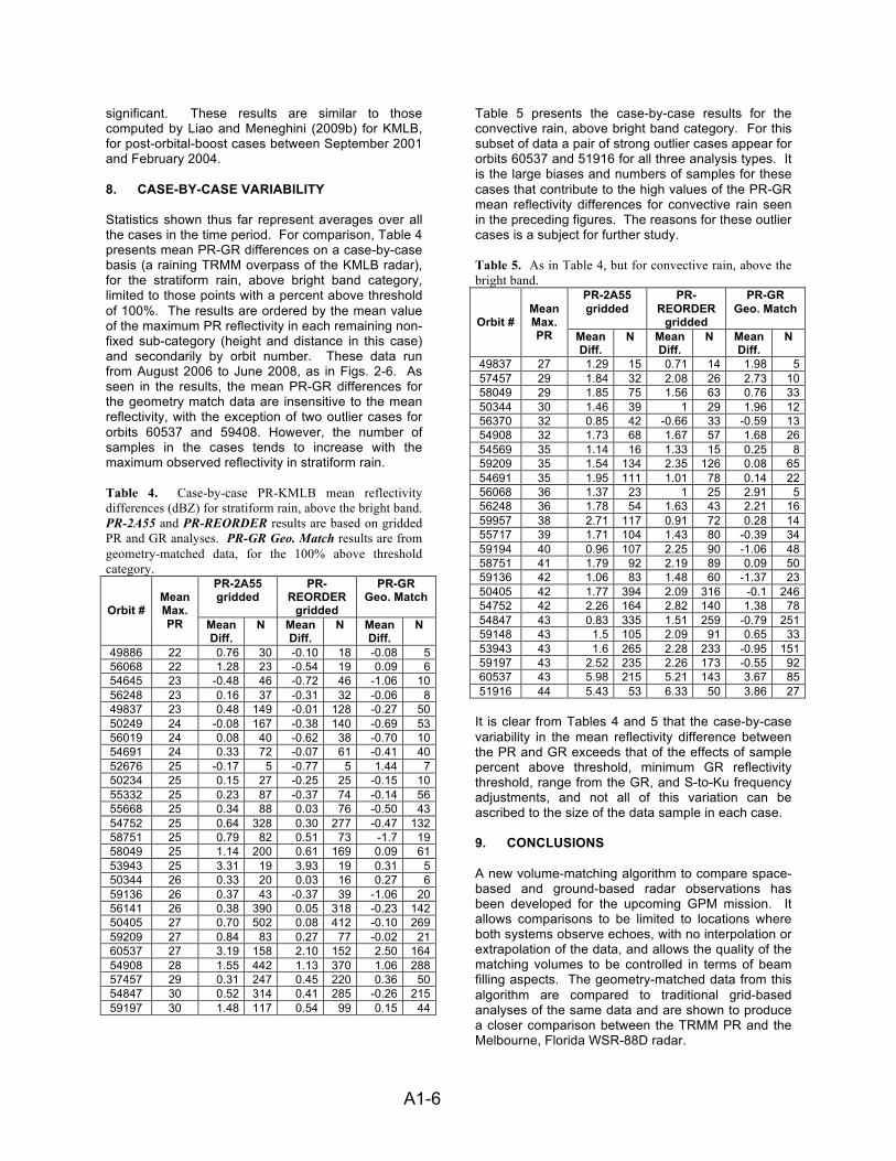
A1-6 !
significant. These results are similar to those computed by Liao and Meneghini (2009b) for KMLB, for post-orbital-boost cases between September 2001 and February 2004. 8. CASE-BY-CASE VARIABILITY Statistics shown thus far represent averages over all the cases in the time period. For comparison, Table 4 presents mean PR-GR differences on a case-by-case basis (a raining TRMM overpass of the KMLB radar), for the stratiform rain, above bright band category, limited to those points with a percent above threshold of 100%. The results are ordered by the mean value of the maximum PR reflectivity in each remaining non-fixed sub-category (height and distance in this case) and secondarily by orbit number. These data run from August 2006 to June 2008, as in Figs. 2-6. As seen in the results, the mean PR-GR differences for the geometry match data are insensitive to the mean reflectivity, with the exception of two outlier cases for orbits 60537 and 59408. However, the number of samples in the cases tends to increase with the maximum observed reflectivity in stratiform rain. Table 4. Case-by-case PR-KMLB mean reflectivity differences (dBZ) for stratiform rain, above the bright band. PR-2A55 and PR-REORDER results are based on gridded PR and GR analyses. PR-GR Geo. Match results are from geometry-matched data, for the 100% above threshold category.
PR-2A55 gridded
PR-REORDER
gridded
PR-GR Geo. Match
Orbit #
Mean Max. PR Mean
Diff. N Mean
Diff. N Mean
Diff. N
49886 22 0.76 30 -0.10 18 -0.08 5 56068 22 1.28 23 -0.54 19 0.09 6 54645 23 -0.48 46 -0.72 46 -1.06 10 56248 23 0.16 37 -0.31 32 -0.06 8 49837 23 0.48 149 -0.01 128 -0.27 50 50249 24 -0.08 167 -0.38 140 -0.69 53 56019 24 0.08 40 -0.62 38 -0.70 10 54691 24 0.33 72 -0.07 61 -0.41 40 52676 25 -0.17 5 -0.77 5 1.44 7 50234 25 0.15 27 -0.25 25 -0.15 10 55332 25 0.23 87 -0.37 74 -0.14 56 55668 25 0.34 88 0.03 76 -0.50 43 54752 25 0.64 328 0.30 277 -0.47 132 58751 25 0.79 82 0.51 73 -1.7 19 58049 25 1.14 200 0.61 169 0.09 61 53943 25 3.31 19 3.93 19 0.31 5 50344 26 0.33 20 0.03 16 0.27 6 59136 26 0.37 43 -0.37 39 -1.06 20 56141 26 0.38 390 0.05 318 -0.23 142 50405 27 0.70 502 0.08 412 -0.10 269 59209 27 0.84 83 0.27 77 -0.02 21 60537 27 3.19 158 2.10 152 2.50 164 54908 28 1.55 442 1.13 370 1.06 288 57457 29 0.31 247 0.45 220 0.36 50 54847 30 0.52 314 0.41 285 -0.26 215 59197 30 1.48 117 0.54 99 0.15 44
Table 5 presents the case-by-case results for the convective rain, above bright band category. For this subset of data a pair of strong outlier cases appear for orbits 60537 and 51916 for all three analysis types. It is the large biases and numbers of samples for these cases that contribute to the high values of the PR-GR mean reflectivity differences for convective rain seen in the preceding figures. The reasons for these outlier cases is a subject for further study. Table 5. As in Table 4, but for convective rain, above the bright band.
PR-2A55 gridded
PR-REORDER
gridded
PR-GR Geo. Match
Orbit #
Mean Max. PR Mean
Diff. N Mean
Diff. N Mean
Diff. N
49837 27 1.29 15 0.71 14 1.98 5 57457 29 1.84 32 2.08 26 2.73 10 58049 29 1.85 75 1.56 63 0.76 33 50344 30 1.46 39 1 29 1.96 12 56370 32 0.85 42 -0.66 33 -0.59 13 54908 32 1.73 68 1.67 57 1.68 26 54569 35 1.14 16 1.33 15 0.25 8 59209 35 1.54 134 2.35 126 0.08 65 54691 35 1.95 111 1.01 78 0.14 22 56068 36 1.37 23 1 25 2.91 5 56248 36 1.78 54 1.63 43 2.21 16 59957 38 2.71 117 0.91 72 0.28 14 55717 39 1.71 104 1.43 80 -0.39 34 59194 40 0.96 107 2.25 90 -1.06 48 58751 41 1.79 92 2.19 89 0.09 50 59136 42 1.06 83 1.48 60 -1.37 23 50405 42 1.77 394 2.09 316 -0.1 246 54752 42 2.26 164 2.82 140 1.38 78 54847 43 0.83 335 1.51 259 -0.79 251 59148 43 1.5 105 2.09 91 0.65 33 53943 43 1.6 265 2.28 233 -0.95 151 59197 43 2.52 235 2.26 173 -0.55 92 60537 43 5.98 215 5.21 143 3.67 85 51916 44 5.43 53 6.33 50 3.86 27
It is clear from Tables 4 and 5 that the case-by-case variability in the mean reflectivity difference between the PR and GR exceeds that of the effects of sample percent above threshold, minimum GR reflectivity threshold, range from the GR, and S-to-Ku frequency adjustments, and not all of this variation can be ascribed to the size of the data sample in each case. 9. CONCLUSIONS A new volume-matching algorithm to compare space-based and ground-based radar observations has been developed for the upcoming GPM mission. It allows comparisons to be limited to locations where both systems observe echoes, with no interpolation or extrapolation of the data, and allows the quality of the matching volumes to be controlled in terms of beam filling aspects. The geometry-matched data from this algorithm are compared to traditional grid-based analyses of the same data and are shown to produce a closer comparison between the TRMM PR and the Melbourne, Florida WSR-88D radar.

A1-7 !
The two attributes that most affect the geometry-match comparison results are shown to be the percent of the matching volumes filled with reflectivity values above the PR detection threshold of approximately 18 dBZ, and the application of S- to Ku-band frequency adjustments to the ground radar data, each of which can change the long-term mean reflectivity differences by up to 1.5 dBZ. Geometry-match and grid-based comparison results for stratiform rain were similar, however for convective rain the PR was much more high-biased against the GR for gridded analysis when compared to the geometry-match result. Mean reflectivity differences were relatively insensitive to the time difference between the PR and GR for the range of time differences allowed in the data set, though the scatter of the point-to-point differences is seen to increase with increasing time differences. Mean PR-GR reflectivity differences as a function of distance from the ground radar trended in opposite directions for stratiform and convective rain, with a maximum absolute difference of about 0.4 dBZ for each. The case-by-case variability of the mean reflectivity differences was shown to exceed the variability in the full data set’s differences resulting from any of the data analysis, categorization, and frequency adjustment methods applied in the study. 10. RESOURCES Time-matched TRMM PR and KMLB WSR-88D data files in original formats, geometry match netCDF data files produced from these data, and the Data User’s Guide for the geometry match data are freely available for download, as is open source code used to perform the geometry matching and generate displays and statistical comparisons between the PR and GR. Refer to the online links within the Validation Network Software and Data Products section of:
http://pmm.nasa.gov/science/ground-validation 11. REFERENCES Anagnostou, E.N., C.A. Morales, and T. Dinku, 2000: The use of TRMM Precipitation Radar observations in determining ground radar calibration biases. J. Atmos. Ocean. Tech., 18, 616-628.
Bolen, S.M. and V. Chandrasekar, 2000: Quantitative cross validation of space-based and ground-based radar observations. J. Appl. Meteor., 39, 2071-2079.
Liao, L., R. Meneghini, and T. Iguichi, 2001: Comparisons of rain rate and reflectivity factor derived from the TRMM Precipitation Radar and the WSR-88D over the Melbourne, Florida, site. J. Atmos. Ocean. Tech., 18, 1959-1974.
Liao, L., R. Meneghini, 2009a: Validation of TRMM Precipitation Radar through Comparison of Its
Multiyear Measurements with Ground-Based Radar. J. Appl. Meteor. Climatol., 48, 804–817.
Liao, L., R. Meneghini, 2009b: Changes in the TRMM Version-5 and Version-6 Precipitation Radar Products due to Orbit Boost. J. Meteor. Soc. Japan, 87A, 93-107.
Schwaller, M. R. and K. R. Morris, 2011: A Ground Validation Network for the Global Precipitation Measurement Mission. J. Atmos. Oceanic Technol., 28, 301–319.
Schumacher, C. and R.A. Houze, 2000: Comparison of Radar Data from the TRMM Satellite and Kwajalein Oceanic Validation Site. J. Appl. Meteor., 39, 2151–2164.
Wolff, D. B., D. A. Marks, E. Amitai, D. S. Silberstein, B. L. Fisher, A. Tokay, J. Wang, and J. L. Pippitt, 2005: Ground validation for the Tropical Rainfall Measuring Mission. J. Atmos. Ocean. Tech, 22, No. 4, 365-380.
Wang, J., D.B. Wolff, 2009: Comparisons of Reflectivities from the TRMM Precipitation Radar and Ground-Based Radars. J. Atmos. Oceanic Technol., 26, 857–875.
Related Documents