S-1134E © 2017-05 Global Data Transmitter Single Prime GPRS/UMTS Eijkelkamp Soil & Water P.O. Box 4, 6987 ZG Giesbeek, the Netherlands T +31 313 880 200 E [email protected] I www.eijkelkamp.com Meet the difference Service manual (original instructions)

Welcome message from author
This document is posted to help you gain knowledge. Please leave a comment to let me know what you think about it! Share it to your friends and learn new things together.
Transcript

S-1134E© 2017-05
Global Data Transmitter Single PrimeGPRS/UMTS
Eijkelkamp Soil & WaterP.O. Box 4, 6987 ZG Giesbeek, the Netherlands
T +31 313 880 200E [email protected] www.eijkelkamp.com
Meet the difference
Service manual (original instructions)
GPRS or UMTS version Internal barometric and temperature sensorData available on Eijkelkamp web portal or e-mail Easy to link to your own web environment (through API)External antenna connectionPowered with standard alkaline batteriesLithium battery pack for intensive use (optional)Real time alarms possible (flood control)Secure data transmissionPlug and play
2S-1134E
Contents
1 Introduction ..................................................................................................................................................... 4 1.1 About this manual ........................................................................................................................................... 4 1.2 Original instructions ....................................................................................................................................... 42 Safety ..................................................................................................................................................... 4 2.1 Symbols in the manual ................................................................................................................................... 4 2.2 Intended use ................................................................................................................................................... 4 2.3Qualificationoftheuser ................................................................................................................................ 4 2.4 Liability ......................................................................................................................................................5 2.5 Regulations and instructions .........................................................................................................................5 2.6 Environment and disposal of waste ............................................................................................................. 63 Product overview ...................................................................................................................................................7 3.1 Outside view .....................................................................................................................................................7 3.2 Inside view ..................................................................................................................................................... 8 3.3 Explanation of the controls ........................................................................................................................... 8 3.4 Technical data ................................................................................................................................................104 Getting started .................................................................................................................................................... 12 4.1 Unpacking .................................................................................................................................................... 12 4.2 Installing batteries ......................................................................................................................................... 12 4.3Settingupfirst-timecommunication ............................................................................................................ 12 4.4 Installation .................................................................................................................................................... 13 4.5 Commissioning ............................................................................................................................................... 155 Operation .................................................................................................................................................... 16 5.1 Data communication ..................................................................................................................................... 16 5.2 Parameter settings ........................................................................................................................................186 Service tool (local connection) ......................................................................................................................... 28 6.1 System requirements .................................................................................................................................... 28 6.2 List of abbreviations ..................................................................................................................................... 28 6.3 Default values ................................................................................................................................................ 28 6.4 General overview ........................................................................................................................................... 28 6.5 Dashboard ................................................................................................................................................... 30 6.6 Modem status .................................................................................................................................................33 6.7 Logger status ..................................................................................................................................................34 6.8 GPRS / UMTS settings ....................................................................................................................................35 6.9 GDT Server settings ........................................................................................................................................36 6.10 Log messages ............................................................................................................................................37 6.11 Baro log ................................................................................................................................................... 38 6.12 Baro log ext .............................................................................................................................................. 40 6.13 Advanced settings ....................................................................................................................................41 6.14 Alarmconfiguration ...................................................................................................................................42 6.15 Production test ..........................................................................................................................................44 6.16 Getting started .......................................................................................................................................... 467 BBT (remote connection) ....................................................................................................................................49 7.1 System requirements .....................................................................................................................................49 7.2 Default values .................................................................................................................................................49 7.3 Login ....................................................................................................................................................49
3 S-1134E
Disclaimer Nothingfromthisdocumentmaybecopiedand/ormadepublicbymeansofprinting,photocopy,microfilmorin any other way without the prior written approval of the publisher. Technical data can change without prior notification.EijkelkampSoil&Waterisnotresponsibleand/orliableforanydamageand/orpersonalinjurydue to (incorrect) use of this product. Eijkelkamp Soil & Water would be pleased to receive your reactions and comments about this product and the user instructions.
8 Maintenance ................................................................................................................................................... 50 8.1 Preparation ................................................................................................................................................... 50 8.2 General inspection overview ........................................................................................................................ 50 8.3 Inspection and cleaning ............................................................................................................................... 50 8.4(Re-)placingthebattery ................................................................................................................................52 8.5(Re-)placingtheSIMcard(optional) ............................................................................................................53 8.6 Storage ....................................................................................................................................................549 Specifications ....................................................................................................................................................54 9.1 Parts list ....................................................................................................................................................54
4S-1134E
1 Introduction
1.1 About this manual
This manual is intended as a reference manual by which service personnel can carry out the maintenance and configurationoftheGlobalDataTransmitterSinglePrimeGPRS(orGDT-SPrimeUMTS),henceforthcalledmodem.For an overview of the modem and its components, refer to chapter 3. Make sure that you• know the contents of this manual; • follow up all directions; • never change the sequence of the procedures.
1.2 Original instructions
The original instructions for this manual have been written in English. Other language versions of this manual are a translation of the original instructions. 2 Safety
2.1 Symbols in the manual
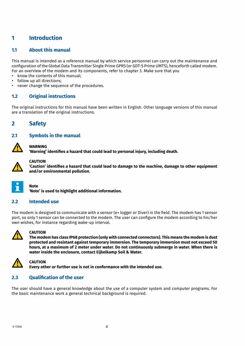
WARNING ‘Warning’ identifies a hazard that could lead to personal injury, including death.
CAUTION ‘Caution’ identifies a hazard that could lead to damage to the machine, damage to other equipment and/or environmental pollution.
Note ‘Note’ is used to highlight additional information.
2.2 Intended use
Themodemisdesignedtocommunicatewithasensor(e+loggerorDiver)inthefield.Themodemhas1sensorport,soonly1sensorcanbeconnectedtothemodem.Theusercanconfigurethemodemaccordingtohis/herownwishes,forinstanceregardingwake-upinterval.
CAUTION The modem has class IP68 protection (only with connected connectors). This means the modem is dust protected and resistant against temporary immersion. The temporary immersion must not exceed 50 hours, at a maximum of 2 meter under water. Do not continuously submerge in water. When there is water inside the enclosure, contact Eijkelkamp Soil & Water.
CAUTION Every other or further use is not in conformance with the intended use.
2.3 Qualification of the user
The user should have a general knowledge about the use of a computer system and computer programs. For the basic maintenance work a general technical background is required.
5 S-1134E
2.4 Liability
The modem is delivered factory sealed with IP68 protection class (50hrs@2mH2O).
CAUTION We prefer not to open the modem in the field. Only open the modem in a clean and dry environment. Avoid unnecessary opening of the modem.
TheIP68protectionclasscanonlybepreservedandguaranteedwhenthefollowingpartsareclean,dust-freeand undamaged:• enclosure; • sealing of the enclosure; • connectors.
Furthermore, make sure that: • The sensor cable is correctly connected. Refer to 4.4.3. • The modem is mounted correctly in the monitoring well. Refer to 4.4.1. • The work is performed according to the local ESD safety regulations. • Only original Eijkelkamp or recommended parts are used.
2.5 Regulations and instructions
2.5.1 Modem
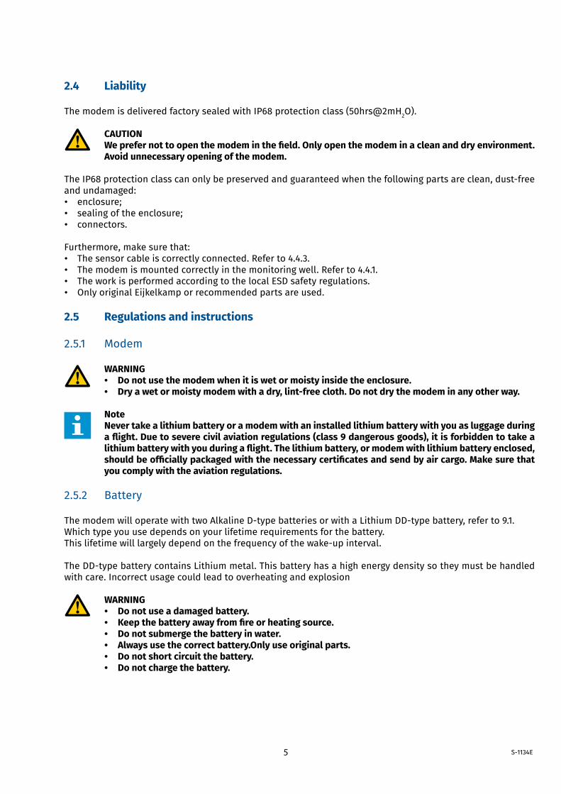
WARNING • Do not use the modem when it is wet or moisty inside the enclosure. • Dry a wet or moisty modem with a dry, lint-free cloth. Do not dry the modem in any other way.
Note Never take a lithium battery or a modem with an installed lithium battery with you as luggage during a flight. Due to severe civil aviation regulations (class 9 dangerous goods), it is forbidden to take a lithium battery with you during a flight. The lithium battery, or modem with lithium battery enclosed, should be officially packaged with the necessary certificates and send by air cargo. Make sure that you comply with the aviation regulations.
2.5.2 Battery
ThemodemwilloperatewithtwoAlkalineD-typebatteriesorwithaLithiumDD-typebattery,referto9.1.Which type you use depends on your lifetime requirements for the battery. Thislifetimewilllargelydependonthefrequencyofthewake-upinterval. TheDD-typebatterycontainsLithiummetal.Thisbatteryhasahighenergydensitysotheymustbehandledwith care. Incorrect usage could lead to overheating and explosion
WARNING • Do not use a damaged battery. • Keep the battery away from fire or heating source. • Do not submerge the battery in water. • Always use the correct battery.Only use original parts. • Do not short circuit the battery. • Do not charge the battery.
6S-1134E
Note Never take a lithium battery or a modem with an installed lithium battery with you as luggage during a flight. Due to severe civil aviation regulations (class 9 dangerous goods), it is forbidden to take a lithium battery with you during a flight. The lithium battery, or modem with lithium battery enclosed, should be officially packaged with the necessary certificates and send by air cargo. Make sure that you comply with the aviation regulations.
2.5.3 Connection
WARNING Do not use worn and/or damaged cables.
2.6 Environment and disposal of waste
CAUTION Always observe the local rules and regulations with respect to processing or disposing of (non-reusable) parts.
CAUTION Always first remove the battery. Refer to 8.4. For correct disposal of the battery, refer to 2.6.2.
2.6.1 Correct disposal of the product
WARNING Do not dispose with other types of waste! This could possibly cause harm to the human health or the environment.
If worn, damaged or not necessary anymore, please return the modem to your local dealer for correct disposal or repair.
2.6.2 Correct disposal of the battery
WARNING Do not dispose with other types of waste! The battery contains substances that can cause harm to the human health or the environment.
To protect natural resources and promote material reuse, separate batteries from other types of waste and recycle them through your local battery return system.
CAUTION Never return the DD-cell battery to the local dealer by air transport because this battery contains lithium.
7 S-1134E
3 Product overview
3.1 Outside view
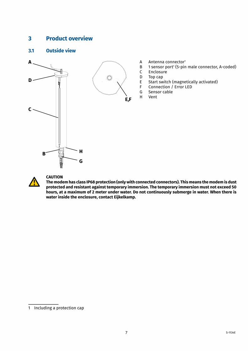
A Antenna connector1
B 1 sensor port1(5-pinmaleconnector,A-coded)C EnclosureD Top capE Start switch (magnetically activated)F Connection / Error LEDG Sensor cableH Vent
CAUTIONThe modem has class IP68 protection (only with connected connectors). This means the modem is dust protected and resistant against temporary immersion. The temporary immersion must not exceed 50 hours, at a maximum of 2 meter under water. Do not continuously submerge in water. When there is water inside the enclosure, contact Eijkelkamp.
1 Including a protection cap
A
E,F
HB
C
D
G
8S-1134E
3.2 Inside view
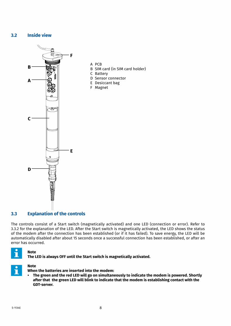
A PCBB SIM card (in SIM card holder) C Battery D Sensor connector E Desiccant bag F Magnet
3.3 Explanation of the controls
The controls consist of a Start switch (magnetically activated) and one LED (connection or error). Refer to 3.3.2 for the explanation of the LED. After the Start switch is magnetically activated, the LED shows the status of the modem after the connection has been established (or if it has failed). To save energy, the LED will be automatically disabled after about 15 seconds once a successful connection has been established, or after an error has occurred.
Note The LED is always OFF until the Start switch is magnetically activated.
Note When the batteries are inserted into the modem: • The green and the red LED will go on simultaneously to indicate the modem is powered. Shortly after that the green LED will blink to indicate that the modem is establishing contact with the GDT-server.
A
B
C
D
E
F
9 S-1134E
3.3.1 Start switch
The Start switch (magnetically activated) is used to initially turn on the modem and afterwards to establish a connection to the GDT Server.
The Start switch is concealed in the top cap. When the Start switch is magnetically activated :• The green LED will blink. • The modem starts to connect to the GDT Server. • When the connection is established the green LED stays on for 15 seconds.
Note It is not possible to turn off the modem by magnetically activating the Start switch.
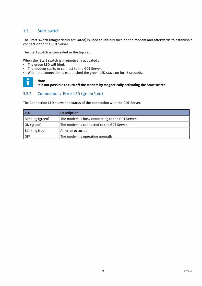
3.3.2 Connection / Error LED (green/red)
The Connection LED shows the status of the connection with the GDT Server.
LED Description
Blinking (green) The modem is busy connecting to the GDT Server.
ON (green) The modem is connected to the GDT Server.
Blinking (red) An error occurred
OFF The modem is operating normally
10S-1134E
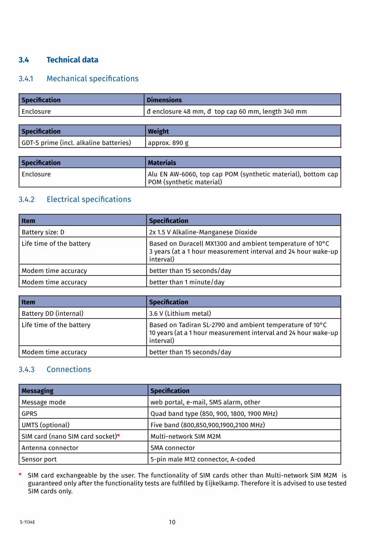
3.4 Technical data
3.4.1 Mechanicalspecifications
Specification Dimensions
Enclosure �enclosure48mm,�topcap60mm,length340mm
Specification Weight
GDT-Sprime(incl.alkalinebatteries) approx. 890 g
Specification Materials
Enclosure AluENAW-6060,topcapPOM(syntheticmaterial),bottomcapPOM (synthetic material)
3.4.2 Electricalspecifications
Item Specification
Battery size: D 2x1.5VAlkaline-ManganeseDioxide
Life time of the battery Based on Duracell MX1300 and ambient temperature of 10°C3years(ata1hourmeasurementintervaland24hourwake-upinterval)
Modem time accuracy better than 15 seconds/day
Modem time accuracy better than 1 minute/day
Item Specification
Battery DD (internal) 3.6 V (Lithium metal)
Life time of the battery BasedonTadiranSL-2790andambienttemperatureof10°C10years(ata1hourmeasurementintervaland24hourwake-upinterval)
Modem time accuracy better than 15 seconds/day
3.4.3 Connections
Messaging Specification
Message mode webportal,e-mail,SMSalarm,other
GPRS Quad band type (850, 900, 1800, 1900 MHz)
UMTS (optional) Five band (800,850,900,1900,2100 MHz)
SIM card (nano SIM card socket)* Multi-networkSIMM2M
Antenna connector SMA connector
Sensor port 5-pinmaleM12connector,A-coded
* SIMcardexchangeablebytheuser.ThefunctionalityofSIMcardsotherthanMulti-networkSIMM2MisguaranteedonlyafterthefunctionalitytestsarefulfilledbyEijkelkamp.ThereforeitisadvisedtousetestedSIM cards only.
11
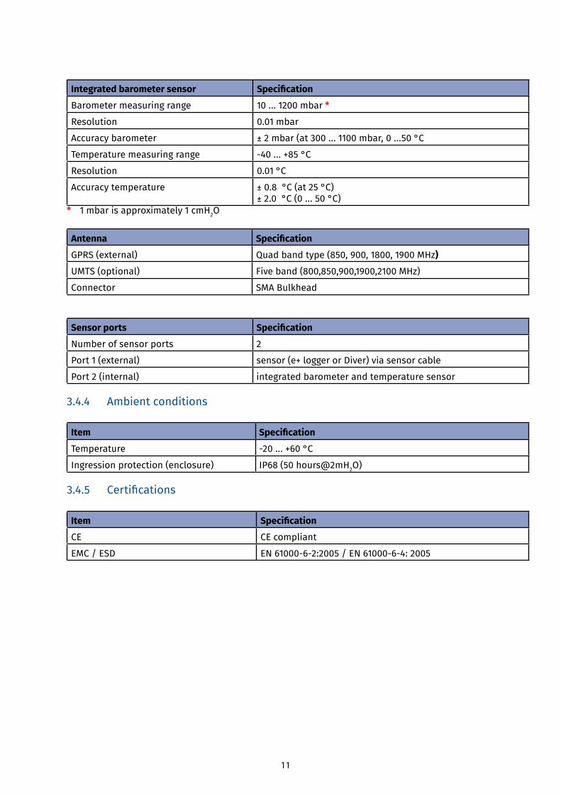
Integrated barometer sensor Specification
Barometer measuring range 10 ... 1200 mbar *
Resolution 0.01 mbar
Accuracy barometer ± 2 mbar (at 300 ... 1100 mbar, 0 ...50 °C
Temperature measuring range -40...+85°C
Resolution 0.01 °C
Accuracy temperature ± 0.8 °C (at 25 °C)± 2.0 °C (0 ... 50 °C)
* 1 mbar is approximately 1 cmH2O
Antenna Specification
GPRS (external) Quad band type (850, 900, 1800, 1900 MHz)
UMTS (optional) Five band (800,850,900,1900,2100 MHz)
Connector SMA Bulkhead
Sensor ports Specification
Number of sensor ports 2
Port 1 (external) sensor (e+ logger or Diver) via sensor cable
Port 2 (internal) integrated barometer and temperature sensor
3.4.4 Ambient conditions
Item Specification
Temperature -20...+60°C
Ingression protection (enclosure) IP68 (50 hours@2mH2O)
3.4.5 Certifications
Item Specification
CE CE compliant
EMC / ESD EN61000-6-2:2005/EN61000-6-4:2005
12
4 Getting started
4.1 Unpacking
1. When unpacking, carefully follow the instructions as given on the packaging or on the product. 2. Check that your delivery is correct and complete. Refer to the order list and the delivery list. If incomplete,
contact Eijkelkamp Soil & Water.
CAUTION Depending on the order, the modem is pre-installed with SIM card. Avoid unnecessary opening of the modem because of the risk of leakage.
3.Checkthedeliveryforanytransportdamage.Reportanydamageimmediatelybyfilingaclaimagainstthecarrier and mark the bill of lading accordingly.
4.2 Installing batteries
Themodemsneedstobefittedwithbatteries,thereforereferto5.4forplacingthem.
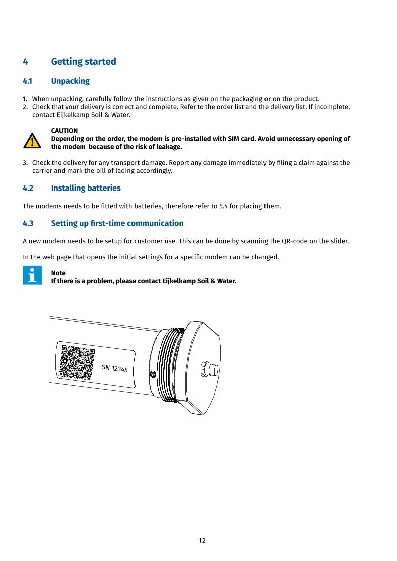
4.3 Setting up first-time communication
Anewmodemneedstobesetupforcustomeruse.ThiscanbedonebyscanningtheQR-codeontheslider.
Inthewebpagethatopenstheinitialsettingsforaspecificmodemcanbechanged.
NoteIf there is a problem, please contact Eijkelkamp Soil & Water.
SN 12345
13
4.4 Installation
CAUTION The guarantee will be void when the modem is not used for its intended use and/or at incorrect installation. Refer to 2.2 and 2.4.
4.4.1 Mounting the modem
CAUTION • Place the modem in a protective environment.2 • Do not expose the modem to direct sunlight. • Avoid deformation of the enclosure. - Do not use too much force when mounting the modem. • The connector should be easily reachable and there should be enough space to connect the cable to the connector. • All parts must be clean and dry prior to installation. • Do not expose the modem to vibration, direct heat sources and/or forms of radiation and magnetism.
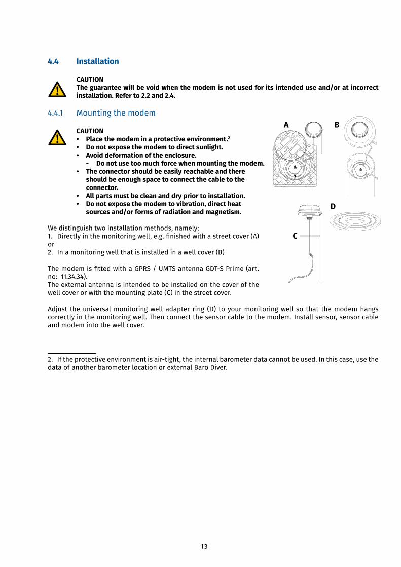
We distinguish two installation methods, namely;1. Directlyinthemonitoringwell,e.g.finishedwithastreetcover(A)or 2. In a monitoring well that is installed in a well cover (B)
ThemodemisfittedwithaGPRS/UMTSantennaGDT-SPrime(art.no: 11.34.34). The external antenna is intended to be installed on the cover of the well cover or with the mounting plate (C) in the street cover.
Adjust the universal monitoring well adapter ring (D) to your monitoring well so that the modem hangs correctly in the monitoring well. Then connect the sensor cable to the modem. Install sensor, sensor cable and modem into the well cover.
2. Iftheprotectiveenvironmentisair-tight,theinternalbarometerdatacannotbeused.Inthiscase,usethedata of another barometer location or external Baro Diver.
A B
D
C
14
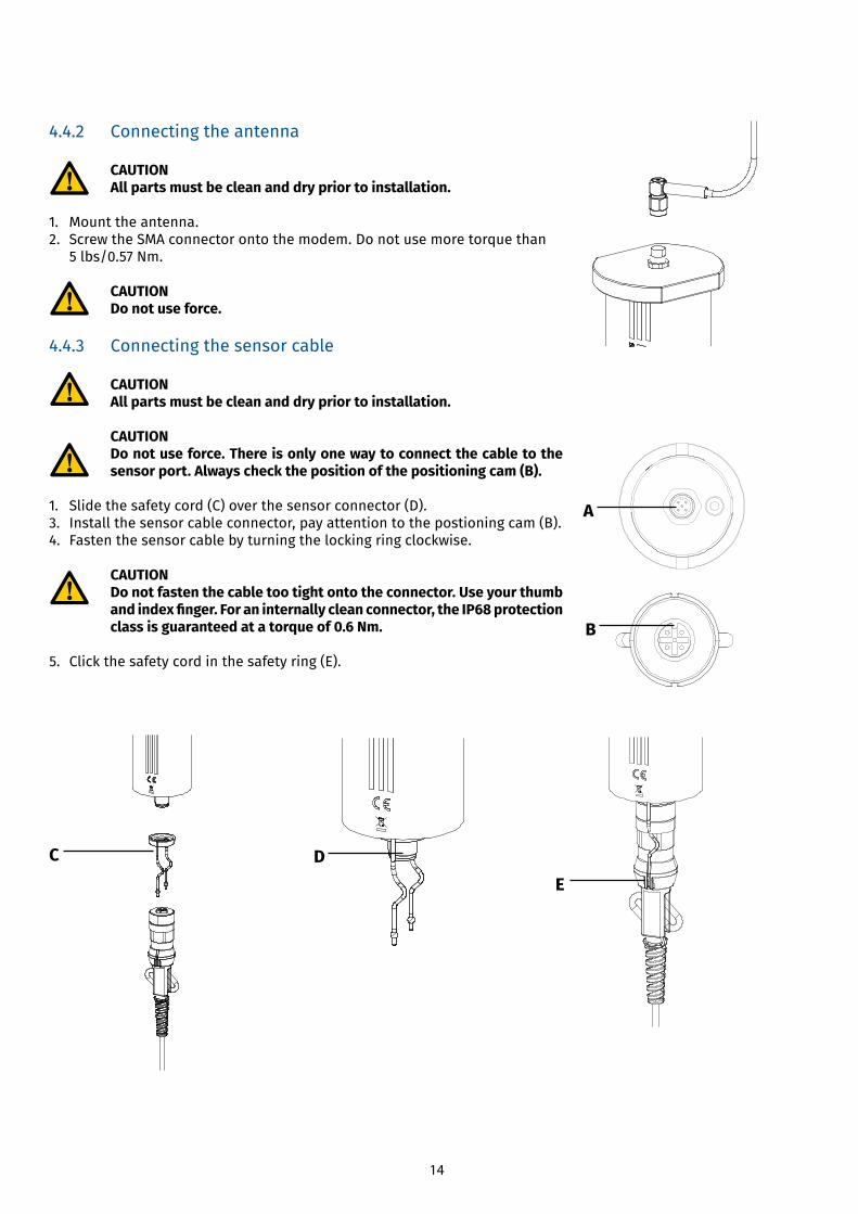
4.4.2 Connecting the antenna
CAUTION All parts must be clean and dry prior to installation.
1. Mount the antenna. 2. Screw the SMA connector onto the modem. Do not use more torque than 5 lbs/0.57 Nm.
CAUTION Do not use force.
4.4.3 Connecting the sensor cable
CAUTION All parts must be clean and dry prior to installation.
CAUTION Do not use force. There is only one way to connect the cable to the sensor port. Always check the position of the positioning cam (B).
1. Slide the safety cord (C) over the sensor connector (D). 3. Install the sensor cable connector, pay attention to the postioning cam (B).4. Fasten the sensor cable by turning the locking ring clockwise.
CAUTION Do not fasten the cable too tight onto the connector. Use your thumb and index finger. For an internally clean connector, the IP68 protection class is guaranteed at a torque of 0.6 Nm.
5. Click the safety cord in the safety ring (E).
A
B
C DE
15
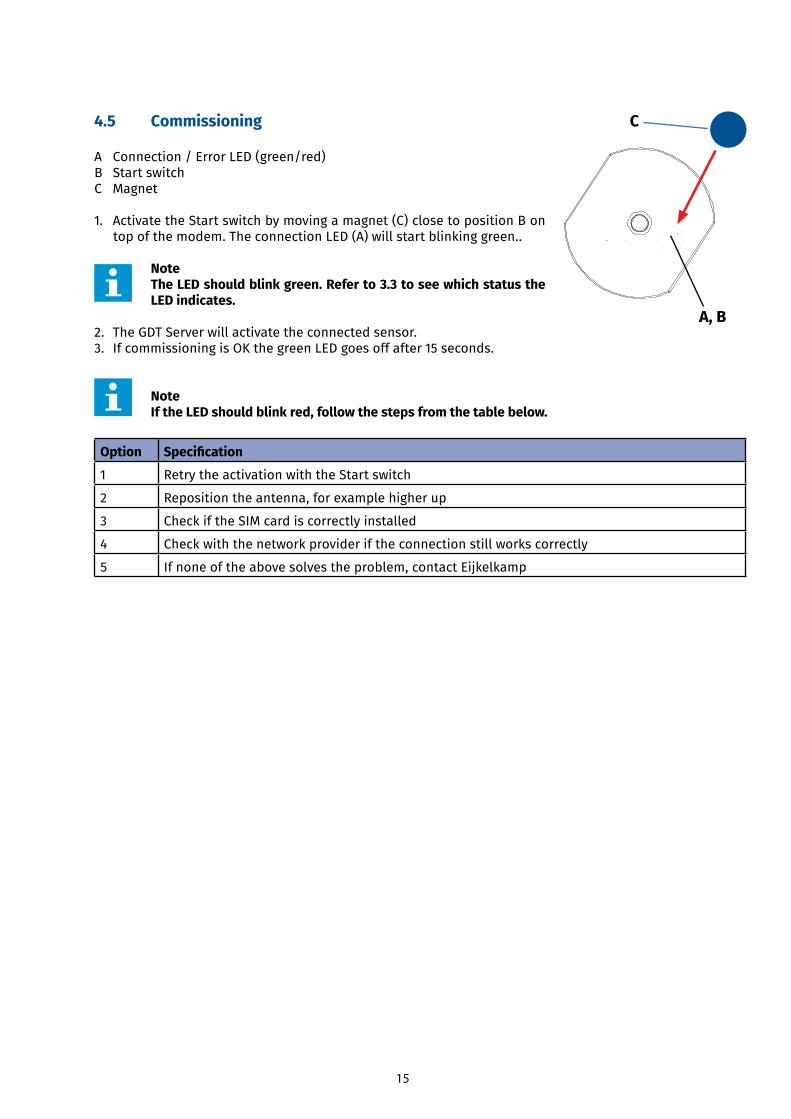
4.5 Commissioning
A Connection / Error LED (green/red)B Start switchC Magnet
1. Activate the Start switch by moving a magnet (C) close to position B on top of the modem. The connection LED (A) will start blinking green..
Note The LED should blink green. Refer to 3.3 to see which status the LED indicates.
2. The GDT Server will activate the connected sensor. 3. If commissioning is OK the green LED goes off after 15 seconds.
Note If the LED should blink red, follow the steps from the table below.
Option Specification
1 Retry the activation with the Start switch
2 Reposition the antenna, for example higher up
3 Check if the SIM card is correctly installed
4 Check with the network provider if the connection still works correctly
5 If none of the above solves the problem, contact Eijkelkamp
A, B
C
16
5 Operation
5.1 Data communication
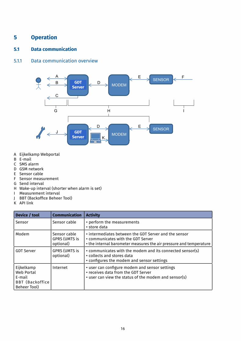
5.1.1 Data communication overview
A Eijkelkamp Webportal B E-mailC SMS alarm D GSM network E Sensor cable F Sensor measurement G Send interval H Wake-upinterval(shorterwhenalarmisset)I Measurement interval J BBT(BackofficeBeheerTool)K API link
Device / tool Communication Activity
Sensor Sensor cable • perform the measurements• store data
Modem Sensor cableGPRS (UMTS isoptional)
• intermediates between the GDT Server and the sensor• communicates with the GDT Server• the internal barometer measures the air pressure and temperature
GDT Server GPRS (UMTS isoptional)
• communicates with the modem and its connected sensor(s)• collects and stores data•configuresthemodemandsensorsettings
Eijkelkamp Web PortalE-mailBBT (Backoffice Beheer Tool)
Internet •usercanconfiguremodemandsensorsettings• receives data from the GDT Server• user can view the status of the modem and sensor(s)
BACK OFFICE
MODEMSENSOR
SENSOR
BACK OFFICE
MODEMSENSOR
SENSOR
AB
C
F
FD
E
E
JK E
G IH
D E
GDT Server
GDT Server
17
Device / tool Communication Activity
(laptop) computer (with service tool)
Service cable • EijkelkampSoil&Water serviceuser can configuremodemandsensor settings• Eijkelkamp Soil & Water service user can view the status of the modem and sensor E
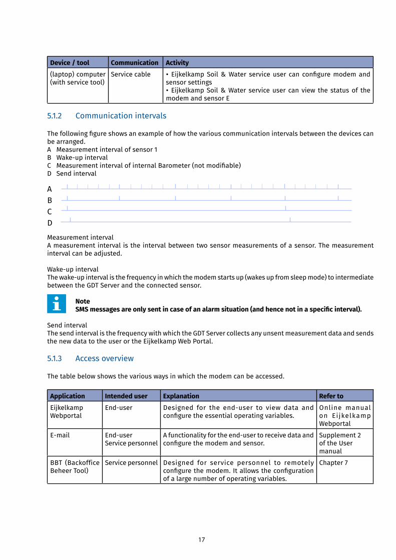
5.1.2 Communication intervals
Thefollowingfigureshowsanexampleofhowthevariouscommunicationintervalsbetweenthedevicescanbe arranged. A Measurement interval of sensor 1 B Wake-upintervalC MeasurementintervalofinternalBarometer(notmodifiable)D Send interval
Measurement interval A measurement interval is the interval between two sensor measurements of a sensor. The measurement interval can be adjusted.
Wake-upintervalThewake-upintervalisthefrequencyinwhichthemodemstartsup(wakesupfromsleepmode)tointermediatebetween the GDT Server and the connected sensor.
Note SMS messages are only sent in case of an alarm situation (and hence not in a specific interval).
Send interval The send interval is the frequency with which the GDT Server collects any unsent measurement data and sends the new data to the user or the Eijkelkamp Web Portal.
5.1.3 Access overview
The table below shows the various ways in which the modem can be accessed.
Application Intended user Explanation Refer to
Eijkelkamp Webportal
End-user Designed for the end-user to view data andconfiguretheessentialoperatingvariables.
Online manual on Ei jkelkamp Webportal
E-mail End-userService personnel
Afunctionalityfortheend-usertoreceivedataandconfigurethemodemandsensor.
Supplement 2of the Usermanual
BBT (Backoffice Beheer Tool)
Service personnel Designed for service personnel to remotely configurethemodem.Itallowstheconfigurationof a large number of operating variables.
Chapter 7
BCD
A
18
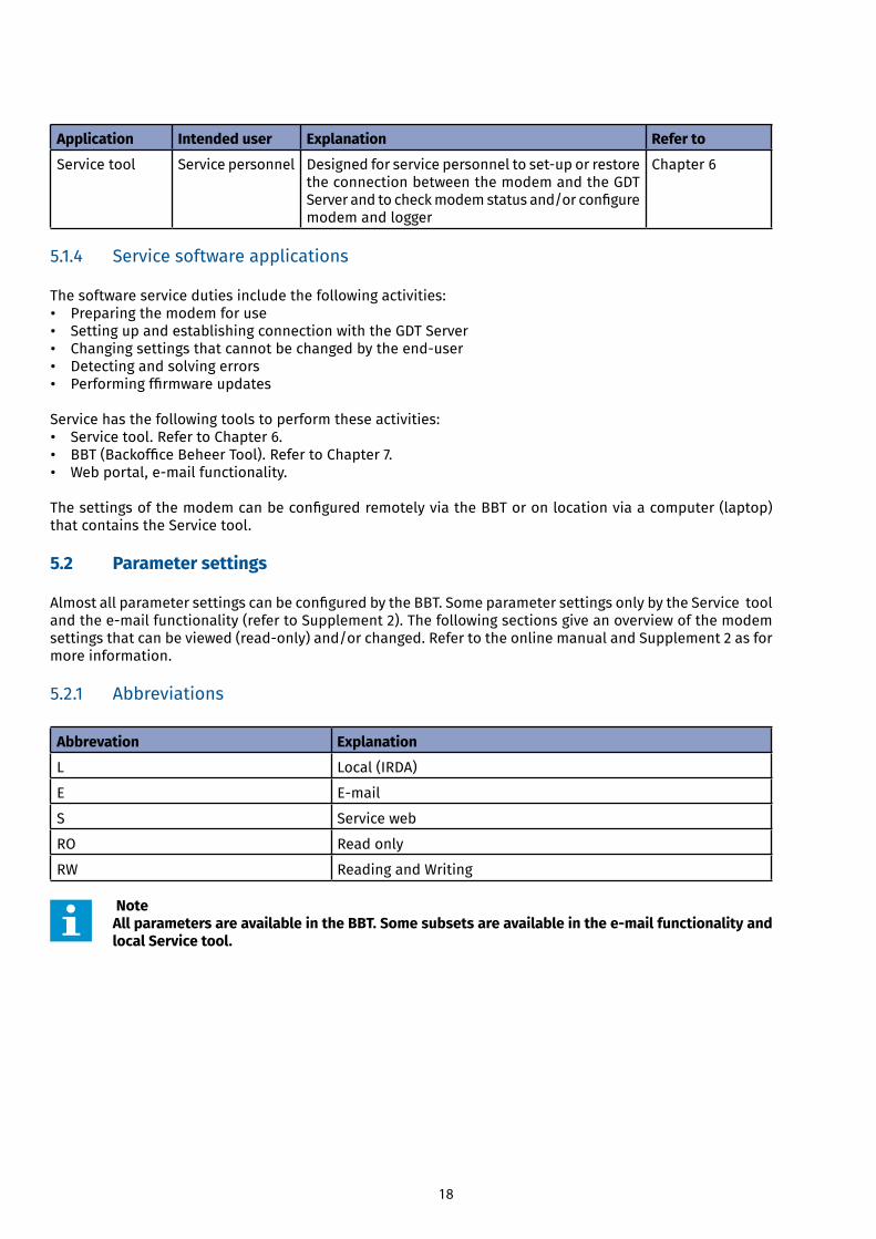
Application Intended user Explanation Refer to
Service tool Service personnel Designedforservicepersonneltoset-uporrestorethe connection between the modem and the GDT Serverandtocheckmodemstatusand/orconfiguremodem and logger
Chapter 6
5.1.4 Service software applications
The software service duties include the following activities:• Preparing the modem for use • Setting up and establishing connection with the GDT Server • Changingsettingsthatcannotbechangedbytheend-user• Detecting and solving errors • Performingffirmwareupdates
Service has the following tools to perform these activities:• Service tool. Refer to Chapter 6. • BBT(BackofficeBeheerTool).RefertoChapter7.• Webportal,e-mailfunctionality.
ThesettingsofthemodemcanbeconfiguredremotelyviatheBBToronlocationviaacomputer(laptop)that contains the Service tool.
5.2 Parameter settings
AlmostallparametersettingscanbeconfiguredbytheBBT.SomeparametersettingsonlybytheServicetoolandthee-mailfunctionality(refertoSupplement2).Thefollowingsectionsgiveanoverviewofthemodemsettingsthatcanbeviewed(read-only)and/orchanged.RefertotheonlinemanualandSupplement2asformore information.
5.2.1 Abbreviations
Abbrevation Explanation
L Local (IRDA)
E E-mail
S Service web
RO Read only
RW Reading and Writing
Note All parameters are available in the BBT. Some subsets are available in the e-mail functionality and local Service tool.
19
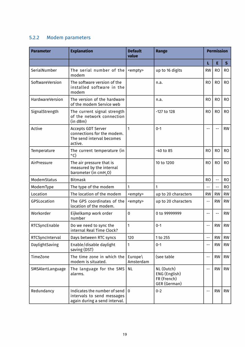
5.2.2 Modem parameters
Parameter Explanation Default value
Range Permission
L E S
SerialNumber The serial number of the modem
<empty> up to 16 digits RW RO RO
SoftwareVersion The software version of theinstalled software in the modem
n.a. RO RO RO
HardwareVersion The version of the hardware of the modem Service web
n.a. RO RO RO
SignalStrength The current signal strength of the network connection (in dBm)
-127to128 RO RO RO
Active Accepts GDT Server connections for the modem. The send interval becomes active.
1 0-1 -- -- RW
Temperature The current temperature (in °C)
-40to85 RO RO RO
AirPressure The air pressure that is measured by the internal barometer (in cmH2O)
10 to 1200 RO RO RO
ModemStatus Bitmask RO -- RO
ModemType The type of the modem 1 1 -- -- RO
Location The location of the modem <empty> up to 20 characters RW RW RW
GPSLocation The GPS coordinates of the location of the modem.
<empty> up to 20 characters -- RW RW
Workorder Eijkelkamp work order number
0 0 to 99999999 -- -- RW
RTCSyncEnable Do we need to sync the internal Real Time Clock?
1 0-1 -- RW RW
RTCSyncInterval Days between RTC syncs 120 1 to 255 -- RW RW
DaylightSaving Enable/disable daylight saving (DST)
1 0-1 -- RW RW
TimeZone The time zone in which the modem is situated.
Europe\Amsterdam
(see table -- RW RW
SMSAlertLanguage The language for the SMS alarms.
NL NL (Dutch)ENG (English)FR (French)GER (German)
-- RW RW
Redundancy Indicates the number of send intervals to send messages again during a send interval.
0 0-2 -- RW RW
20
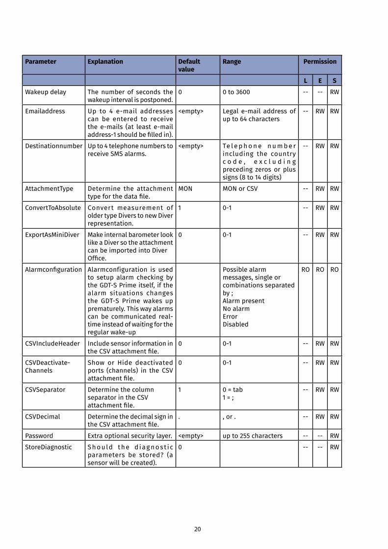
Parameter Explanation Default value
Range Permission
L E S
Wakeup delay The number of seconds the wakeup interval is postponed.
0 0 to 3600 -- -- RW
Emailaddress Up to 4 e-mail addressescan be entered to receive thee-mails (at least e-mailaddress-1shouldbefilledin).
<empty> Legal e-mail addressofup to 64 characters
-- RW RW
Destinationnumber Up to 4 telephone numbers to receive SMS alarms.
<empty> Te l e p h o n e n u m b e r including the country c o d e , e x c l u d i n g preceding zeros or plus signs (8 to 14 digits)
-- RW RW
AttachmentType Determine the attachment typeforthedatafile.
MON MON or CSV -- RW RW
ConvertToAbsolute Convert measurement of older type Divers to new Diver representation.
1 0-1 -- RW RW
ExportAsMiniDiver Make internal barometer look like a Diver so the attachment can be imported into Diver Office.
0 0-1 -- RW RW
Alarmconfiguration Alarmconfiguration is used to setup alarm checking by theGDT-SPrimeitself,ifthealarm situations changes the GDT-S Primewakes upprematurely. This way alarms canbe communicated real-time instead of waiting for the regularwake-up
Possible alarm messages, single or combinations separated by ;Alarm presentNo alarmErrorDisabled
RO RO RO
CSVIncludeHeader Include sensor information in theCSVattachmentfile.
0 0-1 -- RW RW
CSVDeactivate-Channels
Show or Hide deactivated ports (channels) in the CSV attachmentfile.
0 0-1 -- RW RW
CSVSeparator Determine the column separator in the CSV attachmentfile.
1 0 = tab1 = ;
-- RW RW
CSVDecimal Determine the decimal sign in theCSVattachmentfile.
. , or . -- RW RW
Password Extra optional security layer. <empty> up to 255 characters -- -- RW
StoreDiagnostic Shou ld the d iagnost i c parameters be stored? (a sensor will be created).
0 -- -- RW
21
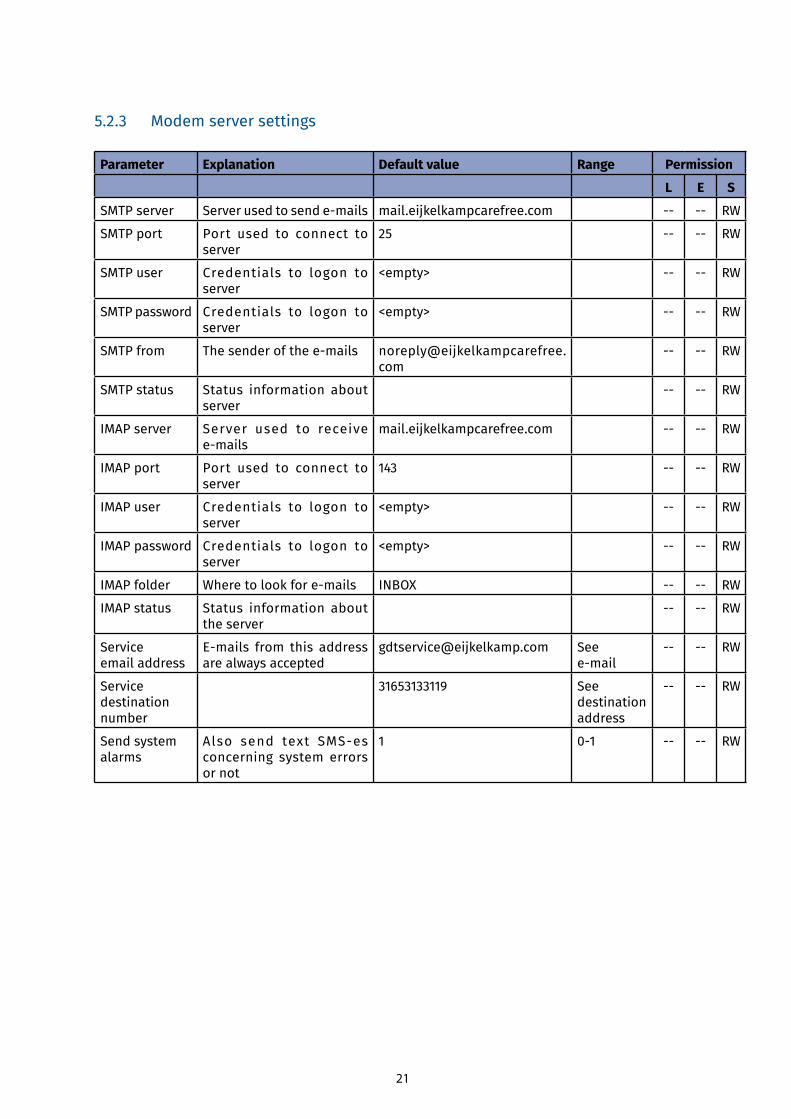
5.2.3 Modem server settings
Parameter Explanation Default value Range Permission
L E S
SMTP server Serverusedtosende-mails mail.eijkelkampcarefree.com -- -- RW
SMTP port Port used to connect to server
25 -- -- RW
SMTP user Credentials to logon to server
<empty> -- -- RW
SMTP password Credentials to logon to server
<empty> -- -- RW
SMTP from Thesenderofthee-mails [email protected]
-- -- RW
SMTP status Status information about server
-- -- RW
IMAP server Server used to receive e-mails
mail.eijkelkampcarefree.com -- -- RW
IMAP port Port used to connect to server
143 -- -- RW
IMAP user Credentials to logon to server
<empty> -- -- RW
IMAP password Credentials to logon to server
<empty> -- -- RW
IMAP folder Wheretolookfore-mails INBOX -- -- RW
IMAP status Status information about the server
-- -- RW
Service email address
E-mails from this addressare always accepted
[email protected] See e-mail
-- -- RW
Service destination number
31653133119 See destinationaddress
-- -- RW
Send system alarms
Also send text SMS-esconcerning system errors or not
1 0-1 -- -- RW
22
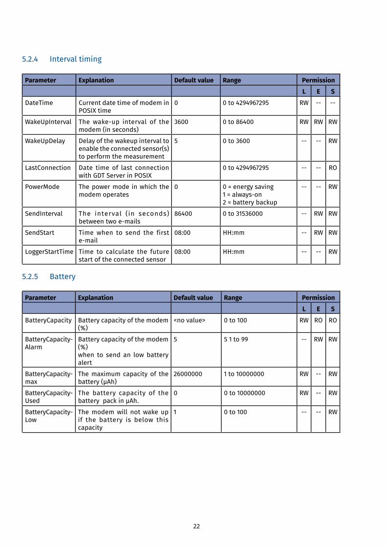
5.2.4 Interval timing
Parameter Explanation Default value Range Permission
L E S
DateTime Current date time of modem in POSIX time
0 0 to 4294967295 RW -- --
WakeUpInterval Thewake-up interval of themodem (in seconds)
3600 0 to 86400 RW RW RW
WakeUpDelay Delay of the wakeup interval to enable the connected sensor(s) to perform the measurement
5 0 to 3600 -- -- RW
LastConnection Date time of last connection with GDT Server in POSIX
0 to 4294967295 -- -- RO
PowerMode The power mode in which the modem operates
0 0 = energy saving1=always-on2 = battery backup
-- -- RW
SendInterval The interval ( in seconds) betweentwoe-mails
86400 0 to 31536000 -- RW RW
SendStart Time when to send the first e-mail
08:00 HH:mm -- RW RW
LoggerStartTime Time to calculate the future start of the connected sensor
08:00 HH:mm -- -- RW
5.2.5 Battery
Parameter Explanation Default value Range Permission
L E S
BatteryCapacity Battery capacity of the modem (%)
<no value> 0 to 100 RW RO RO
BatteryCapacity-Alarm
Battery capacity of the modem (%)when to send an low battery alert
5 5 1 to 99 -- RW RW
BatteryCapacity-max
The maximum capacity of the battery(μAh)
26000000 1 to 10000000 RW -- RW
BatteryCapacity-Used
The battery capacity of the batterypackinμAh.
0 0 to 10000000 RW -- RW
BatteryCapacity-Low
The modem will not wake up if the battery is below this capacity
1 0 to 100 -- -- RW
23
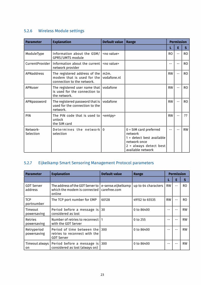
5.2.6 Wireless Module settings
Parameter Explanation Default value Range Permission
L E S
ModuleType Information about the GSM/GPRS/UMTS module
<no value> RO -- RO
CurrentProvider Information about the current network provider
<no value> -- -- RO
APNaddress The registered address of the modem that is used for the connection to the network.
m2m.vodafone.nl
RW -- RO
APNuser The registered user name that is used for the connection to the network.
vodafone RW -- RO
APNpassword The registered password that is used for the connection to the network.
vodafone RW -- RO
PIN The PIN code that is used to unlockthe SIM card
<emtpy> RW -- ??
Network-Selection
Determines the network selection
0 0 = SIM card preferred network1 = detect best available network once2 = always detect best available network
-- -- RW
5.2.7 Eijkelkamp Smart Sensoring Management Protocol parameters
Parameter Explanation Default value Range Permission
L E S
GDT Serveraddress
The address of the GDT Server to which the modem is connected online
e-sense.eijkelkampcarefree.com
up to 64 characters RW -- RO
TCP portnumber
The TCP port number for EMP 60128 49152 to 65535 RW -- RO
Timeout powersaving
Period before a message is considered as lost
30 0 to 86400 -- -- RW
Retries powersaving
Number of retries to reconnect with the GDT Server
1 0 to 255 -- -- RW
Retryperiodpowersaving
Period of time between the retries to reconnect with the GDT Server
300 0 to 86400 -- -- RW
Timeout always on
Period before a message is considered as lost (always on)
300 0 to 86400 -- -- RW
24
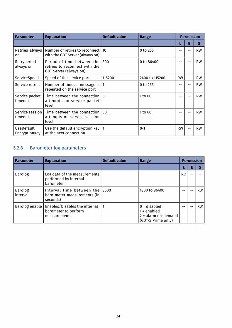
Parameter Explanation Default value Range Permission
L E S
Retries always on
Number of retries to reconnect with the GDT Server (always on)
10 0 to 255 -- -- RW
Retryperiod always on
Period of time between the retries to reconnect with the GDT Server (always on)
300 0 to 86400 -- -- RW
ServiceSpeed Speed of the service port 115200 2400 to 115200 RW -- RW
Service retries Number of times a message is repeated on the service port
1 0 to 255 -- -- RW
Service packettimeout
Time between the connection attempts on service packet level.
5 1 to 60 -- -- RW
Service session timeout
Time between the connection attempts on service session level
30 1 to 60 -- -- RW
UseDefaultEncryptionKey
Use the default encryption key at the next connection
1 0-1 RW -- RW
5.2.8 Barometer log parameters
Parameter Explanation Default value Range Permission
L E S
Barolog Log data of the measurements performed by internal barometer
RO -- --
Barolog interval
Interval time between the baro-metermeasurements (inseconds)
3600 1800 to 86400 -- -- RW
Barolog enable Enables/Disables the internal barometer to perform measurements
1 0 = disabled1 = enabled2=alarmon-demand(GDT-SPrimeonly)
-- -- RW
25
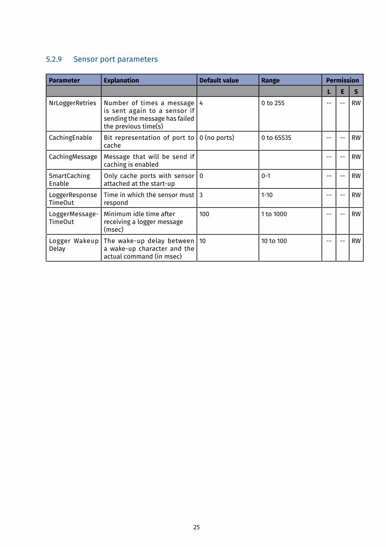
5.2.9 Sensor port parameters
Parameter Explanation Default value Range Permission
L E S
NrLoggerRetries Number of times a message is sent again to a sensor if sending the message has failed the previous time(s)
4 0 to 255 -- -- RW
CachingEnable Bit representation of port to cache
0 (no ports) 0 to 65535 -- -- RW
CachingMessage Message that will be send if caching is enabled
-- -- RW
SmartCachingEnable
Only cache ports with sensor attachedatthestart-up
0 0-1 -- -- RW
LoggerResponseTimeOut
Time in which the sensor must respond
3 1-10 -- -- RW
LoggerMessage-TimeOut
Minimum idle time after receiving a logger message (msec)
100 1 to 1000 -- -- RW
Logger Wakeup Delay
Thewake-up delay betweenawake-up character and theactual command (in msec)
10 10 to 100 -- -- RW
26
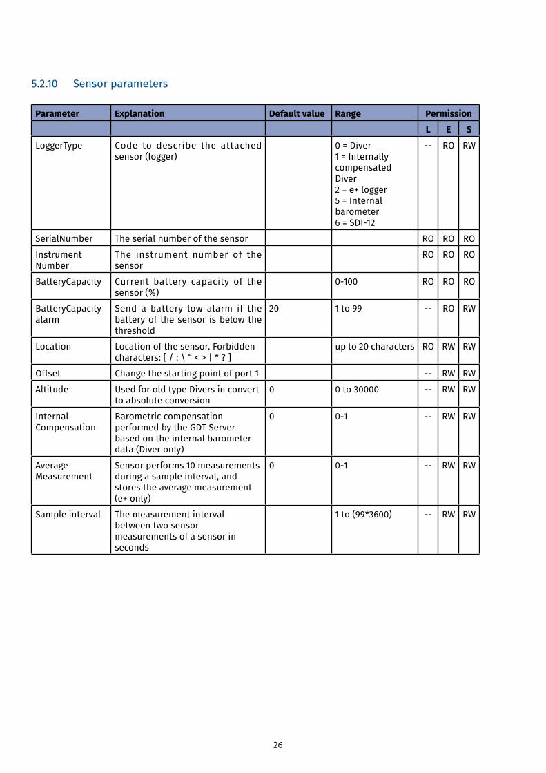
5.2.10 Sensor parameters
Parameter Explanation Default value Range Permission
L E S
LoggerType Code to describe the attached sensor (logger)
0 = Diver 1 = Internally compensated Diver 2 = e+ logger 5 = Internal barometer6=SDI-12
-- RO RW
SerialNumber The serial number of the sensor RO RO RO
InstrumentNumber
The instrument number of the sensor
RO RO RO
BatteryCapacity Current battery capacity of the sensor (%)
0-100 RO RO RO
BatteryCapacityalarm
Send a battery low alarm if the battery of the sensor is below the threshold
20 1 to 99 -- RO RW
Location Location of the sensor. Forbidden characters: [ / : \ “ < > | * ? ]
up to 20 characters RO RW RW
Offset Change the starting point of port 1 -- RW RW
Altitude Used for old type Divers in convert to absolute conversion
0 0 to 30000 -- RW RW
InternalCompensation
Barometric compensation performed by the GDT Server based on the internal barometer data (Diver only)
0 0-1 -- RW RW
AverageMeasurement
Sensor performs 10 measurements during a sample interval, and stores the average measurement (e+ only)
0 0-1 -- RW RW
Sample interval The measurement interval between two sensor measurements of a sensor in seconds
1 to (99*3600) -- RW RW
27
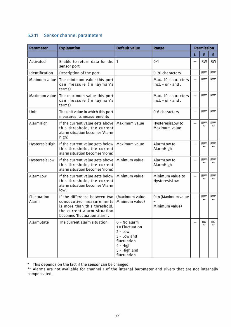
5.2.11 Sensor channel parameters
Parameter Explanation Default value Range Permission
L E S
Activated Enable to return data for the sensor port
1 0-1 -- RW RW
Identification Description of the port 0-20characters -- RW* RW*
Minimum value The minimum value this port can measure (in layman’s terms)
Max. 10 characters incl.+or-and.
-- RW* RW*
Maximum value The maximum value this port can measure (in layman’s terms)
Max. 10 characters incl.+or-and.
-- RW* RW*
Unit The unit value in which this port measures its measurements
0-6characters -- RW* RW*
AlarmHigh If the current value gets above this threshold, the current alarm situation becomes ‘Alarm high’.
Maximum value HysteresisLow to Maximum value
-- RW***
RW***
HysteresisHigh If the current value gets below this threshold, the current alarm situation becomes ‘none’.
Maximum value AlarmLow to AlarmHigh
-- RW***
RW***
HysteresisLow If the current value gets above this threshold, the current alarm situation becomes ‘none’.
Minimum value AlarmLow to AlarmHigh
-- RW***
RW***
AlarmLow If the current value gets below this threshold, the current alarm situation becomes ‘Alarm low’.
Minimum value Minimum value to HysteresisLow
-- RW***
RW***
FluctuationAlarm
If the difference between two consecutive measurements is more than this threshold, the current alarm situation becomes‘fluctuationalarm’.
(Maximum value –Minimum value)
0 to (Maximum value –Minimum value)
-- RW***
RW***
AlarmState The current alarm situation. 0 = No alarm1 = Fluctuation 2 = Low 3 = Low and fluctuation4 = High 5 = High and fluctuation
-- RO**
RO**
* This depends on the fact if the sensor can be changed. ** Alarms are not available for channel 1 of the internal barometer and Divers that are not internally compensated.
28
6 Service tool (local connection)
6.1 System requirements
Application Version
Windows Windows 7 or higher
.net 3.5
USB 1.1
Required: Service interface (art. no. 11.31.19) to connect a laptop with the modem to check and change the modemconfigurationinthefield.
6.2 List of abbreviations
Abbrevation Explanation
RO Read-Only
RW Reading and Writing permission
6.3 Default values
The screens in this chapter show example values. These are not necessarily the default values. Refer to 5.2 for the default values.
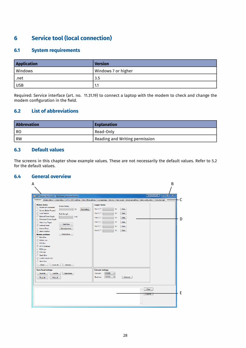
6.4 General overview A B
C
D
E
29
A Software application name and version B Minimise, Maximise and Close buttons C Menu tabs D Data and settings pane E Status box
6.4.1 Menu tabs
The table below shows the menu tabs.
Menu tab Refer to
Dashboard 6.5
Modem status 6.6
Logger status 6.7
GPRS/UMTS settings 6.8
Backofficesettings 6.9
Log messages 6.10
Baro log 6.11
Baro log ext 6.12
Advanced settings 6.13
Alarmconfiguration 6.14
Production test 6.15
6.4.2 Status box
The status box displays information from the different tabs of the software to see which actions the software is performing or has performed. This way the user can see if the software is performing an action or not.
Button Function
Clear Clears the text box
Copy all Copies all information to the clip board
30
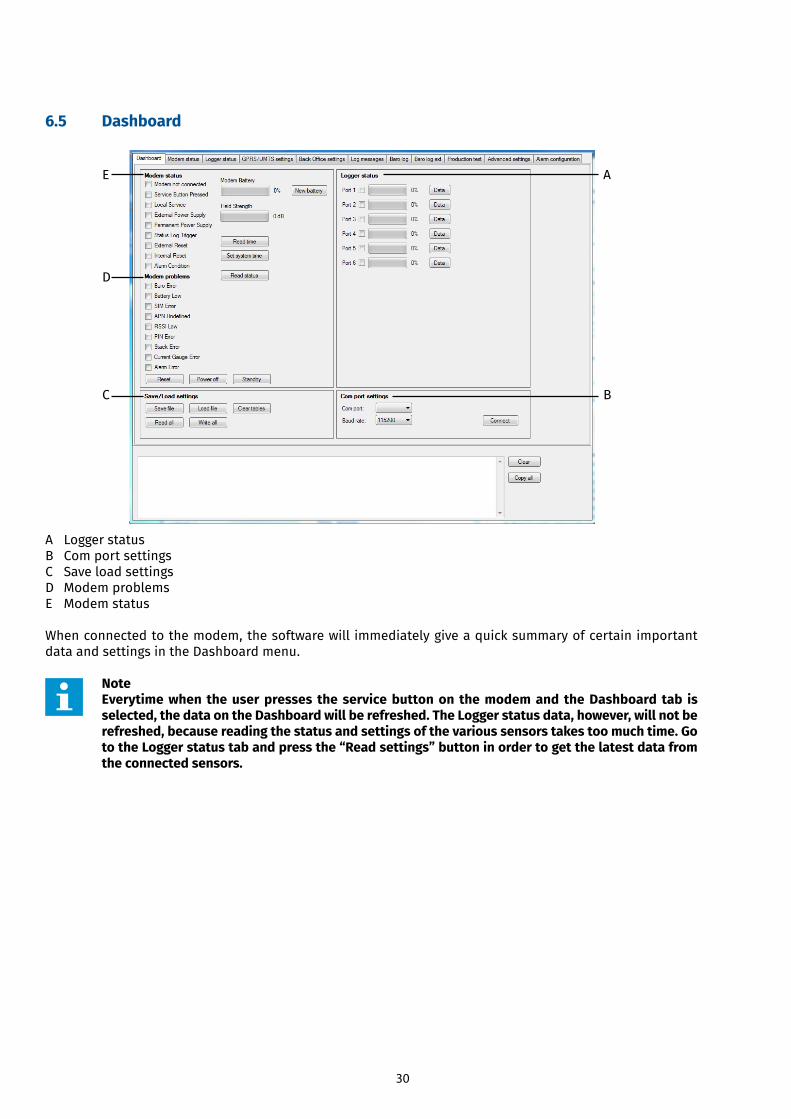
6.5 Dashboard
A Logger status B Com port settings C Save load settings D Modem problems E Modem status
When connected to the modem, the software will immediately give a quick summary of certain important data and settings in the Dashboard menu.
Note Everytime when the user presses the service button on the modem and the Dashboard tab is selected, the data on the Dashboard will be refreshed. The Logger status data, however, will not be refreshed, because reading the status and settings of the various sensors takes too much time. Go to the Logger status tab and press the “Read settings” button in order to get the latest data from the connected sensors.
A
B
E
D
C
31
6.5.1 Modem status
Modem status Explanation (if the box is thicked)
Modem not connected The modem does not have a connection with the GDT Server.
Service button pressed The Start switch button is pressed. The software will read the latest data.
Local Service Indicates that there is a logical connection to the modem.
External Power Supply An external power supply is connected to the modem.
Permanent Power Supply The battery is connected to the modem.
Status Log Trigger Indicates that something has changed in the status bits of the modem.
External reset Indicates that the modem is reset by an external agent (GDT Server/BBT/ Service USB tool)
Internal reset Indicates that the modem has reset itself.
Alarm condition An alarm conditions has occurred
Modem problems Explanation
Baro error The internal barometer has an error.
Battery Low The battery capacity of the modem is too low.
SIM error The SIM card has an error or the SIM card cannot be read.
APNUndefined TheAPN(AccessPointName)isnotdefined.Thereisnonetworkconnection.
RSSI Low Indicates that the signal strength is low.
PIN Error Indicates that the wrong PIN code or no PIN code is entered.
Stack Error Indicates that there is a memory error.
Current Gauge Error Indicates that there is an error in the part that measures the power consumption.
Alarm error Indicates that there is an error when reading the measure values from the logger (s)
Buttons and status bars Explanation
Modem battery (%) Indicator that shows the battery capacity in %.
New battery Informs the GDT Server server that a new battery is installed. The battery capacity indicator will turn to 100% full.
Field strength (dB) Indicator that shows the signal strength of the network at the modem location in dB.
Read time Enables the user to read the set date / time of the modem.
Set system time Adjusts the date / time of the modem to the date / time of the connected computer.
Read status Refresh/Read the modem status
Reset Enables the user to reset the modem.
Power off Enables the user to put the modem in the Power off mode.
Standby Enables the user to put the modem in the Standby mode.
32
CAUTION Do not press the New battery button without having installed a new battery. The modem cannot operate with an empty battery. • The Baro data will get lost and the modem cannot measure new Baro data. • The modem cannot send new measurement data to the user.
6.5.2 Logger status
Logger status Explanation
Port The tick box shows if a sensor is connected to the port. There is 1 sensor port on the modem.
Reading status (%) Status bar that shows the status of the battery capacity of the connected sensor.
Data Retrieves the collected data. Through a wizard you can save the data onto a selected location.
6.5.3 Com port settings
Com port settings Explanation
Com port Enables the user to select the com port.
Baud rate Enables the user to select the baud rate (only 115200).
Connect Makes the connection to the com port.
6.5.4 Save/Load settings
Save/load settings Explanation
Savefile Saves the settings for the current connection only.
Loadfile Loadsexternalsettingsfromasettingsfile.Throughawizardyoucanselectthesettingsfilethatyouwanttouse.
Clear tables Clears all settings in all the tables of all the tabs at once.
Read all Enables the user to read all the settings at once.
Write all Enables the user to write all the settings at once.
33
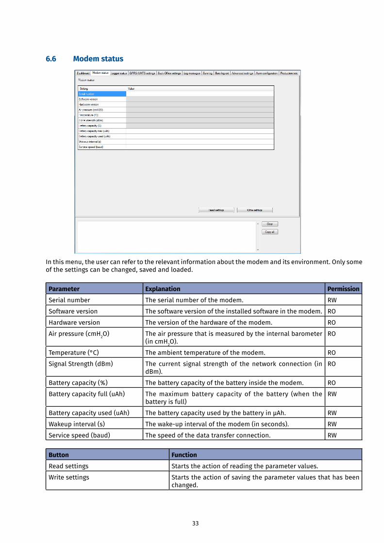
6.6 Modem status
In this menu, the user can refer to the relevant information about the modem and its environment. Only some of the settings can be changed, saved and loaded.
Parameter Explanation Permission
Serial number The serial number of the modem. RW
Software version The software version of the installed software in the modem. RO
Hardware version The version of the hardware of the modem. RO
Air pressure (cmH2O) The air pressure that is measured by the internal barometer (in cmH2O).
RO
Temperature (°C) The ambient temperature of the modem. RO
Signal Strength (dBm) The current signal strength of the network connection (in dBm).
RO
Battery capacity (%) The battery capacity of the battery inside the modem. RO
Battery capacity full (uAh) The maximum battery capacity of the battery (when the battery is full)
RW
Battery capacity used (uAh) ThebatterycapacityusedbythebatteryinμAh. RW
Wakeup interval (s) Thewake-upintervalofthemodem(inseconds). RW
Service speed (baud) The speed of the data transfer connection. RW
Button Function
Read settings Starts the action of reading the parameter values.
Write settings Starts the action of saving the parameter values that has been changed.
34
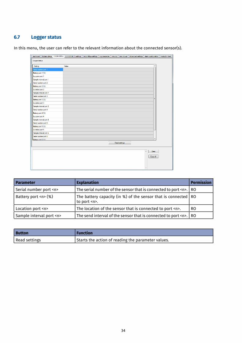
6.7 Logger status
In this menu, the user can refer to the relevant information about the connected sensor(s).
Parameter Explanation Permission
Serial number port <n> The serial number of the sensor that is connected to port <n>. RO
Battery port <n> (%) The battery capacity (in %) of the sensor that is connected to port <n>.
RO
Location port <n> The location of the sensor that is connected to port <n>. RO
Sample interval port <n> The send interval of the sensor that is connected to port <n>. RO
Button Function
Read settings Starts the action of reading the parameter values.
35
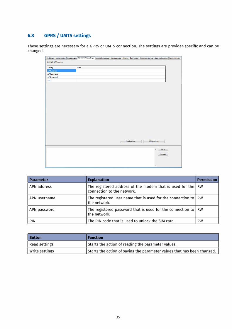
6.8 GPRS / UMTS settings
ThesesettingsarenecessaryforaGPRSorUMTSconnection.Thesettingsareprovider-specificandcanbechanged.
Parameter Explanation Permission
APN address The registered address of the modem that is used for the connection to the network.
RW
APN username The registered user name that is used for the connection to the network.
RW
APN password The registered password that is used for the connection to the network.
RW
PIN The PIN code that is used to unlock the SIM card. RW
Button Function
Read settings Starts the action of reading the parameter values.
Write settings Starts the action of saving the parameter values that has been changed.
36
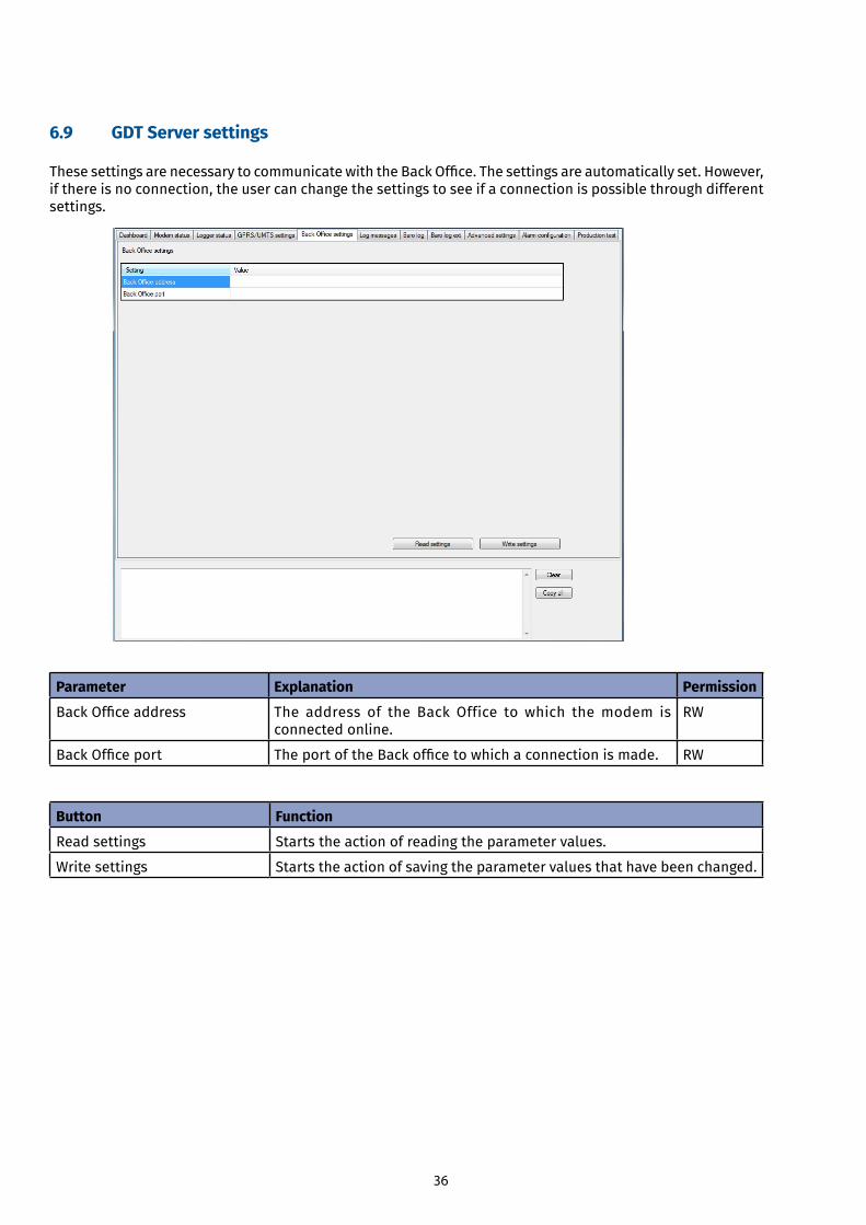
6.9 GDT Server settings
ThesesettingsarenecessarytocommunicatewiththeBackOffice.Thesettingsareautomaticallyset.However,if there is no connection, the user can change the settings to see if a connection is possible through different settings.
Parameter Explanation Permission
BackOfficeaddress The address of the Back Office to which the modem is connected online.
RW
BackOfficeport TheportoftheBackofficetowhichaconnectionismade. RW
Button Function
Read settings Starts the action of reading the parameter values.
Write settings Starts the action of saving the parameter values that have been changed.
37
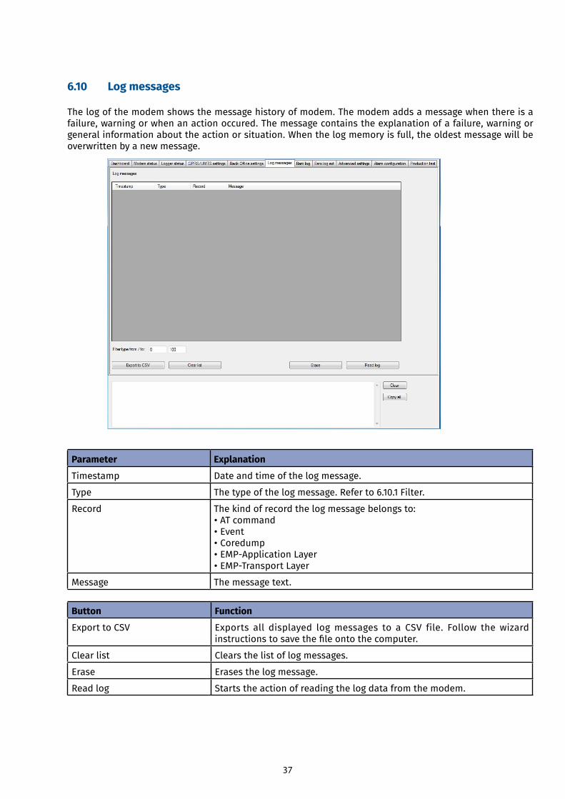
6.10 Log messages
The log of the modem shows the message history of modem. The modem adds a message when there is a failure, warning or when an action occured. The message contains the explanation of a failure, warning or general information about the action or situation. When the log memory is full, the oldest message will be overwritten by a new message.
Parameter Explanation
Timestamp Date and time of the log message.
Type The type of the log message. Refer to 6.10.1 Filter.
Record The kind of record the log message belongs to: • AT command • Event • Coredump •EMP-ApplicationLayer•EMP-TransportLayer
Message The message text.
Button Function
Export to CSV Exports all displayed log messages to a CSV file. Follow the wizard instructionstosavethefileontothecomputer.
Clear list Clears the list of log messages.
Erase Erases the log message.
Read log Starts the action of reading the log data from the modem.
38
6.10.1 Filter
Thefilter(“Filtertypefrom/to:”)hastwofieldsinwhichtheusercaninsertthetypesoflogmessageshewants to read.
Note The filter is only applied to the view. When exporting to a CSV file, all logs are stored.
Filter code Filter type Explanation
0 to 50 Error Error messages
100 Info 1 All sorts of important events, e.g. automatic identificationofwirelessmodule.
125 Info 2 Events that display the current status of the session (mostly at the start of a session).
150 Detailed info 1 Packages (including the contents) of the communication with the Back Officeserver.
175 Detailed info 2 e.g. incorrectly executed AT commands
200 to 255 Detailed info 3 e.g. successfully executed AT commands
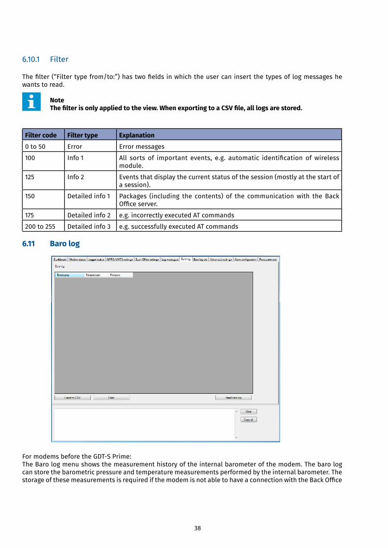
6.11 Baro log
FormodemsbeforetheGDT-SPrime:The Baro log menu shows the measurement history of the internal barometer of the modem. The baro log can store the barometric pressure and temperature measurements performed by the internal barometer. The storageofthesemeasurementsisrequiredifthemodemisnotabletohaveaconnectionwiththeBackOffice
39
Server for a long time. The pressure measurements are crucial in case barometric compensation must be applied. For a reliable barometric compensation, the air pressure should be recorded at least every 4 hours.
Because the barometer does not have its own interval, the barometric measurements are connected to the regularwake-upinterval.Onlywhenthemodembecomesactive(wakesup),thebarometerwillperformitsmeasurements.Therefore,thewake-upintervalshouldnotbelongerthan4hours.Thebarologmemoryhasspace for approximately 85 entries (with a measurement interval of 4 hours, the baro log will be full after 2 weeks). After the log memory is full, the oldest measurement data will be overwritten by new measurement data. However, if the wakeup interval is much shorter than 4 hours, for example only 15 minutes, the baro log memory will become full too fast. Therefore there is an extra parameter that indicates the ‘ideal’ interval periodforthebarolog.Whenthemodembecomesactive,itwillcalculatewhetherthenextwake-upmomentis still within the ‘ideal’ interval period. If this is the case, the barometer will perform the measurements at thenextwake-upmoment.
ThebarometeroftheGDT-SPrimehasitsownintervalthereforeitcanbesetupseparately.
Parameter Explanation
Timestamp Date and time of the measurement
Temperature The measured ambient temperature.
Pressure The measured air pressure.
Button Function
Export to CSV ExportsalllogmessagestoaCSVfile.Followthewizardinstructionstosavethefileontothecomputer.
Clear Clears the list of measurement data.
Read baro log Starts the action of reading and showing the measurement data that is stored in the modem.
40
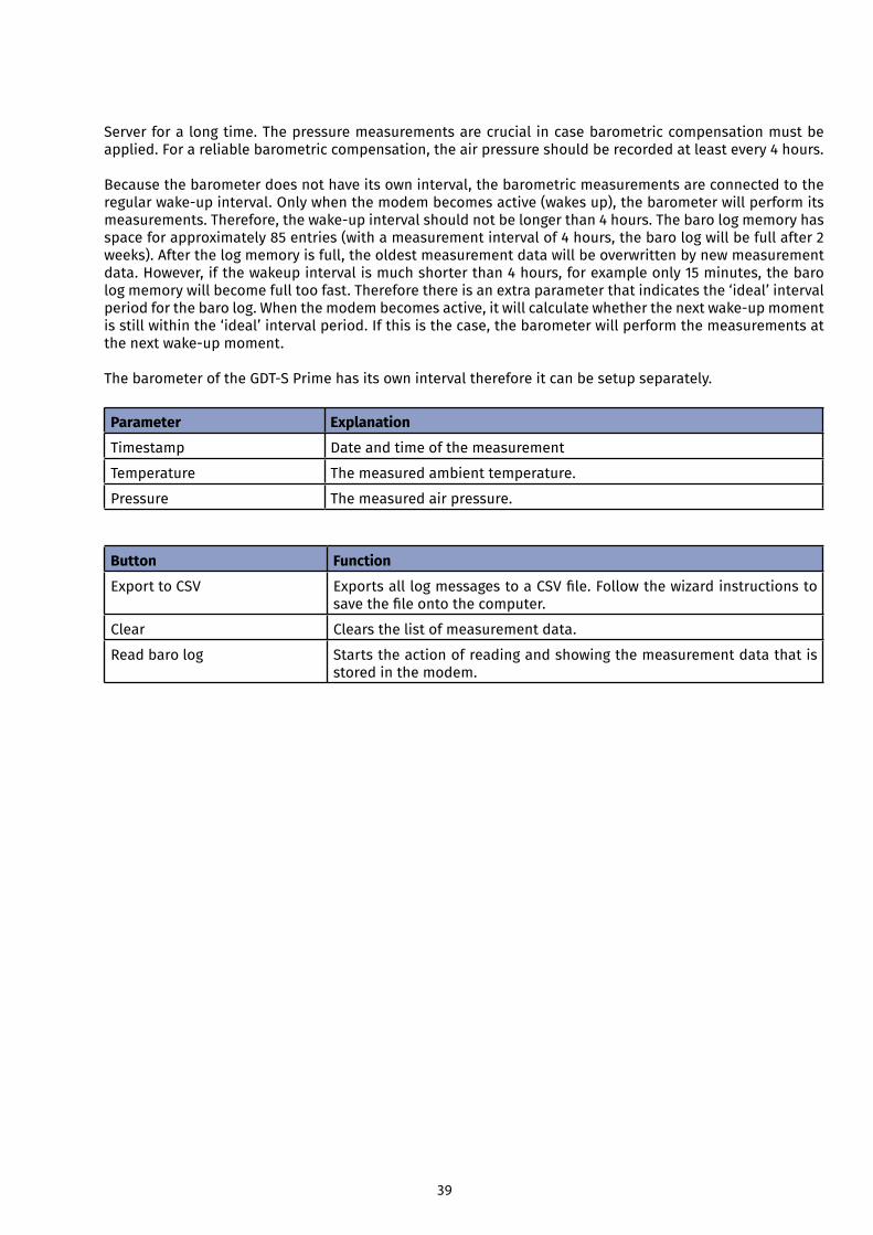
6.12 Baro log ext
The log of the internal Baro logger shows the latest 85 measurements.FromGDTS-PrimetheBarologisincreasesfrom85to2048records.
Parameter Explanation Permission
BaroLog start Absolute time reference for measurement points RO
BaroLogfirstrec Indicesnumberfromthefirstdatarecord RO
BaroLog last rec Indices number from the last data record RO
Timestamp Date and time of the measurement
Temperature The measured ambient temperature
Pressure The measured air pressure
Button Function
Read settings Starts the action of reading and showing the measurement data that is stored in the modem.
41
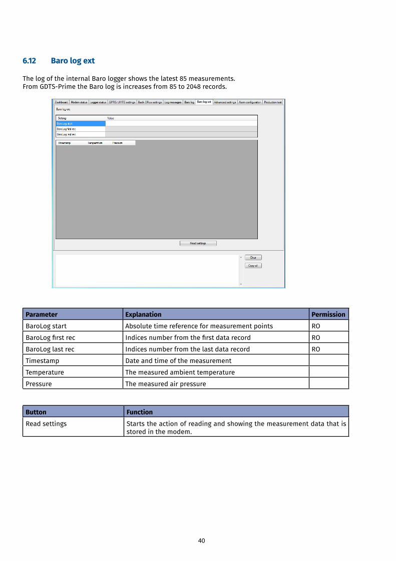
6.13 Advanced settings
6.13.1 Advanced settings
Button Function
Default Encryption key on next logon Requests the GDT Server to generate a new encryption key when the modem is logged on the next time.
Note The “Default Encryption key on next logon” parameter also needs to be configured in the GDT Server!
6.13.2 AT commands
Button / field Function
Start Sets the modem in the AT command mode. Without pressing the Start button, the user cannot send AT commands to the modem.
Stop Sets the modem in the normal working mode.
Send Sends the AT command to the modem.
AT commands input Inthisfieldtheusercantypethecommandsregardingthetasksyou want the module of the modem to perform.
Receive Receives the reply message from the modem.
AT commands output Inthisfield,replymessagesfromthemoduleofthemodemwillappear.
42
6.13.3 Firmware update
Button Function
Selectfile Enablestheusertoselectavalidfirmwarefile.Followthewizardinstructions.
Update Starts theactionofupdatingthefirmwareof themodem.Thestatusbarshowstheprogressofthefirmwareupdate.
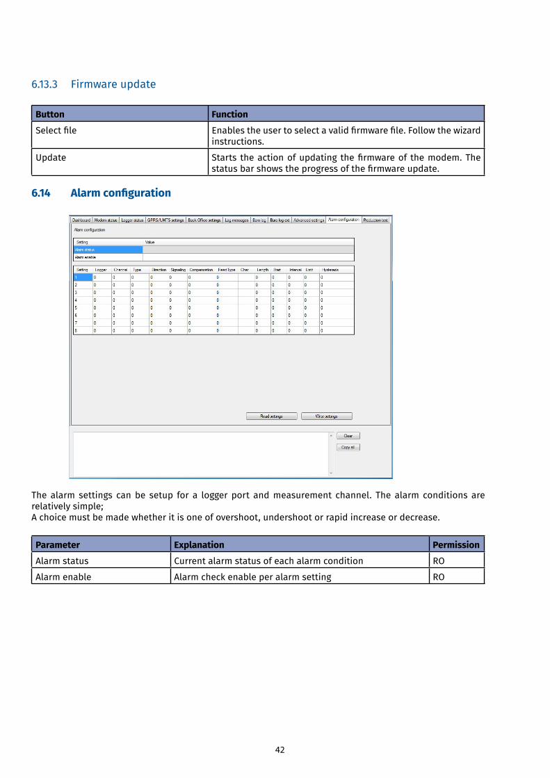
6.14 Alarm configuration
The alarm settings can be setup for a logger port and measurement channel. The alarm conditions are relatively simple;A choice must be made whether it is one of overshoot, undershoot or rapid increase or decrease.
Parameter Explanation Permission
Alarm status Current alarm status of each alarm condition RO
Alarm enable Alarm check enable per alarm setting RO
43
Parameter Explanation
Setting Number of settings
Logger Logger port from the measurement channel on which the alarm configurationisset.
Channel Sensorchannelonwhichthealarmconfigurationisset.
Type Setting of alarm conditions 0=Limit, 1=Fluctuation.
Direction Setting of alarm conditions 0=Above, 1=Below.
Signaling Setting of alarm conditions 0=Start, 1=Start and end.
Compensation Setting of alarm conditions 0=Normal, 1=Compensation.
ReadType Type of command for the purpose of protocol: 0=Diver protocol, 131= e+ protocol.
Char Read command to retrieve most recent result of the logger channel depending on the number of channels. Type logger Channel Channel Channel 1 2 32 channel V v 3 channel V U v
Length Read-lengthinbytes,use16.
Start Reference (start) time when alarm conditions are evaluated.
Interval Maximum time period between two alarm checks.
Limit Limit value at which the alarm condition occurs.
Hysteresis Hysteresis value at which the alarm condition is corrected.
Button Function
Read settings Starts the action of reading the parameter values
Write settings Starts the action of saving the parameter values that have been changed
44
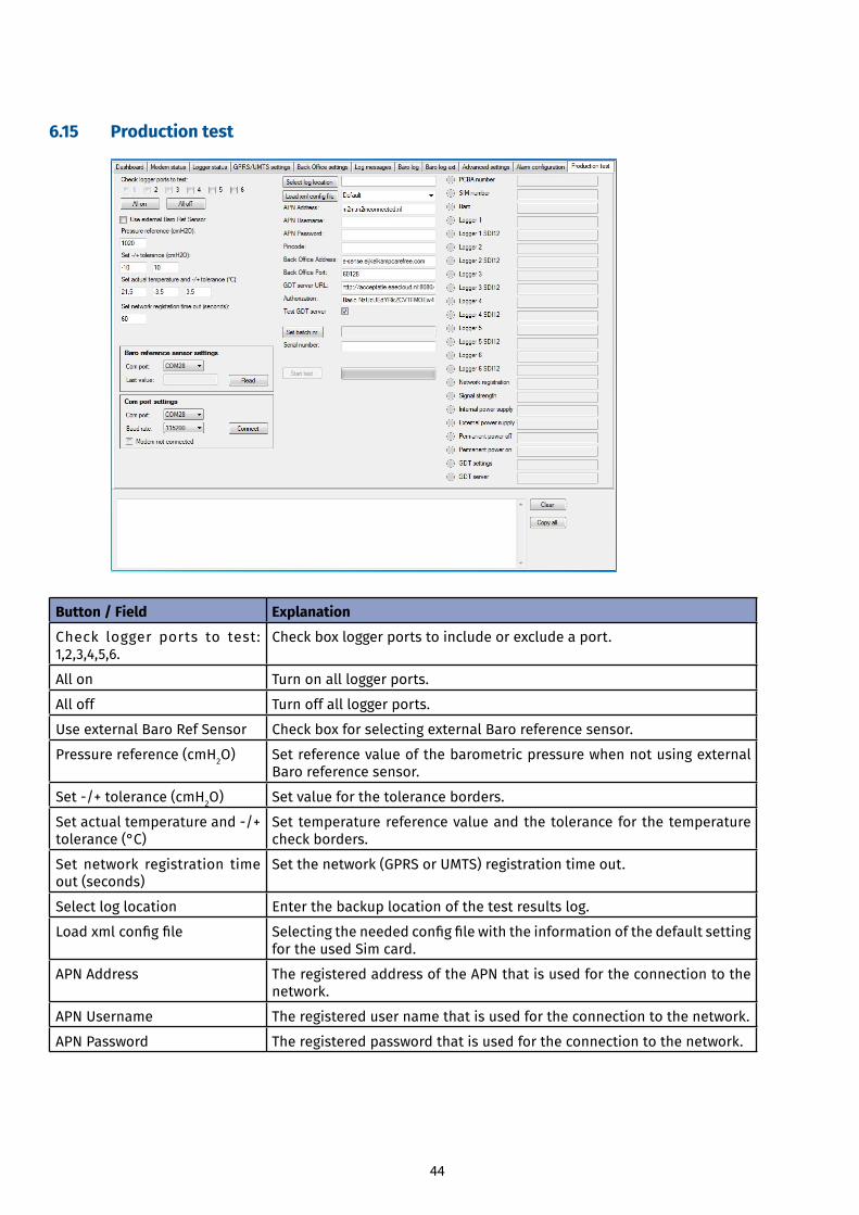
6.15 Production test
Button / Field Explanation
Check logger ports to test: 1,2,3,4,5,6.
Check box logger ports to include or exclude a port.
All on Turn on all logger ports.
All off Turn off all logger ports.
Use external Baro Ref Sensor Check box for selecting external Baro reference sensor.
Pressure reference (cmH2O) Set reference value of the barometric pressure when not using external Baro reference sensor.
Set-/+tolerance(cmH2O) Set value for the tolerance borders.
Setactualtemperatureand-/+tolerance (°C)
Set temperature reference value and the tolerance for the temperature check borders.
Set network registration time out (seconds)
Set the network (GPRS or UMTS) registration time out.
Select log location Enter the backup location of the test results log.
Loadxmlconfigfile Selectingtheneededconfigfilewiththeinformationofthedefaultsettingfor the used Sim card.
APN Address The registered address of the APN that is used for the connection to the network.
APN Username The registered user name that is used for the connection to the network.
APN Password The registered password that is used for the connection to the network.
45
Pincode The PIN code that is used to unlock the SIM card.
BackOfficeAddress TheaddressoftheBackOfficetowhichthemodemisconnectedonline.
BackOfficePort TheportoftheBackOfficetowhichaconnectionismade.
GDT server URL The URL of the GDT server.
Authorization Authorization key for the GDT server.
Test GDT server Check box for including or excluding the connection to the GDT server in the test.
Set batch nr. The batch number of the PCB.
Serial number The serial number of the modem.
Start test Starts the production test.
6.15.1 Baro reference sensor settings
Button / Field Explanation
Com port Enables the user to select the com port
Read Starts the action of reading the parameter value.
Last value Shows the last read value.
6.15.2 Com poert settings
Com port settings Explanation
Com port Enables the user to select the com port
Baud rate Enables the user to select the baud rate (only 115200).
Connect Makes the connection to the com port.
Modem not connected Info box to see if the modem is correctly connected.
46
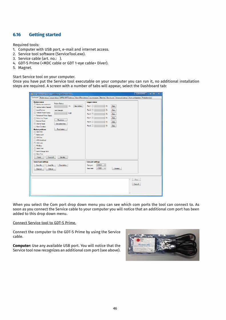
6.16 Getting started
Required tools: 1. ComputerwithUSBport,e-mailandinternetaccess.2. Service tool software (ServiceTool.exe).3. Service cable (art. no.: ).4. GDT-SPrime(+MDCcableorGDT1-eyecable+Diver).5. Magnet.
Start Service tool on your computer.Once you have put the Service tool executable on your computer you can run it, no additional installation steps are required. A screen with a number of tabs will appear, select the Dashboard tab:
When you select the Com port drop down menu you can see which com ports the tool can connect to. As soon as you connect the Service cable to your computer you will notice that an additional com port has been added to this drop down menu.
ConnectServicetooltoGDT-SPrime.
ConnectthecomputertotheGDT-SPrimebyusingtheServicecable.
Computer: Use any available USB port. You will notice that the Service tool now recognizes an additional com port (see above).
47
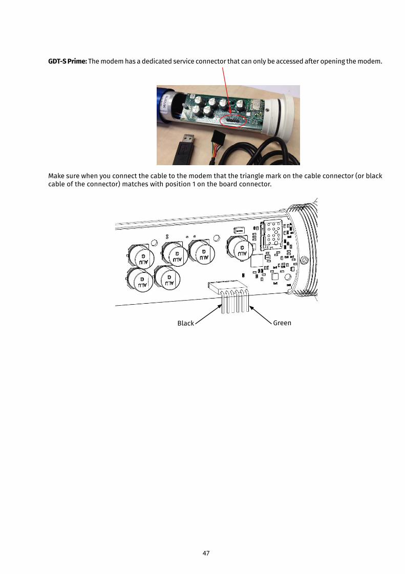
GDT-S Prime: The modem has a dedicated service connector that can only be accessed after opening the modem.
Make sure when you connect the cable to the modem that the triangle mark on the cable connector (or black cable of the connector) matches with position 1 on the board connector.
Black Green
48
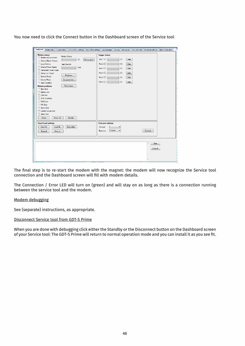
You now need to click the Connect button in the Dashboard screen of the Service tool
Thefinalstep is tore-start themodemwiththemagnet: themodemwillnowrecognizetheServicetoolconnectionandtheDashboardscreenwillfillwithmodemdetails.
The Connection / Error LED will turn on (green) and will stay on as long as there is a connection running between the service tool and the modem.
Modem debugging
See (separate) instructions, as appropriate.
DisconnectServicetoolfromGDT-SPrime
When you are done with debugging click either the Standby or the Disconnect button on the Dashboard screen ofyourServicetool:TheGDT-SPrimewillreturntonormaloperationmodeandyoucaninstallitasyouseefit.
49
7 BBT (remote connection)
7.1 System requirements
Note It is only possible to remotely communicate with the modem if the modem is online. Modem and sensor settings are handled by the modem at the next wake-up. Server settings are handled at the mailcheck (the default time is 5 minutes before wake-up).
Requirements
Internet connection
Web browser
7.2 Default values
The screens in this chapter show example values. These are not necessarily the default values. Refer to 5.2 for the default values.
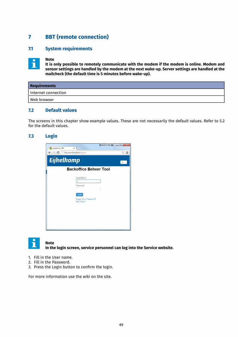
7.3 Login
Note In the login screen, service personnel can log into the Service website.
1. Fill in the User name. 2. Fill in the Password. 3. PresstheLoginbuttontoconfirmthelogin.
For more information use the wiki on the site.
50
8 Maintenance
8.1 Preparation
CAUTION Only original parts must be used, otherwise the guarantee will be void.
Make sure you take with you the following tools and accessories:• Cloth(clean,dryandlint-free);• Replacement desiccant kit. Refer to 9.1. • Replacement battery. Refer to 9.1. • Replacement SIM card (optional). • Replacement antenna. • Replacement cables and sensor.
8.2 General inspection overview
The modem requires little maintenance. However, if you need to do maintenance work, always check the following points during maintenance.
Inspection Check Action (if required)
Enclosure (external) Dirt / Humidity Cleananddrywithadry,lint-freecloth.
Enclosure (internal) Humidity Replace the desiccant kit. Refer to 8.3.6.If wet or moisty, contact Eijkelkamp.
Sensor cable Wear or damage Replace the cable.
Antenna Wear or damage Replace the antenna.
SIM card Refer to 8.5
Note It is advised always to take a replacement battery with you. Check the battery capacity level beforehand via the Eijkelkamp Webportal or the e-mail functionality. Refer to the Online Manual or to Supplement 2 on how to check the battery capacity level.
Note Never take a lithium battery or a modem with an installed lithium battery with you as luggage during a flight. Due to severe civil aviation regulations (class 9 dangerous goods), it is forbidden to take a lithium battery with you during a flight.
8.3 Inspection and cleaning
CAUTIONWe advise you to take the necessary ESD safety regulations for the modem during assembly. (When the O-rings are damaged, contact Eijkelkamp Soil & Water.)
8.3.1 Inspecting and cleaning the outside of the modem
1. Check the outside of the modem for dirt and humidity. Pay special attention to the vent. The vent has to be free of dirt. Never use sharp tools to clean.
2. Cleananddrythemodemwithadry,lint-freecloth.
51
8.3.2 Dismounting the modem
Note If you need to open the enclosure, it is advised to remove the modem from the measuring site, so the modem can be taken to a clean and dry environment.
1. Check if the cable and connector are still connected correctly. Also check the cable and connector for possible defects.
2. Disconnect the antenna from the antenna connector. Turn the hexagon locking counter clockwise. 3. Disconnect the sensor cable from the sensor port. Turn the locking ring counter clockwise. 4. Cleantheantennaconnectorandsensorportwithadry,lint-freecloth.5. Take the modem to a clean and dry environment.
8.3.3 Opening the enclosure
CAUTION Do not open the modem in the field. Only open the modem in a clean and dry environment.
Note It is advised not to open the enclosure unless it is really necessary (e.g. for placing / replacing the batteries). Opening the enclosure increases the risk of leakage afterwards.
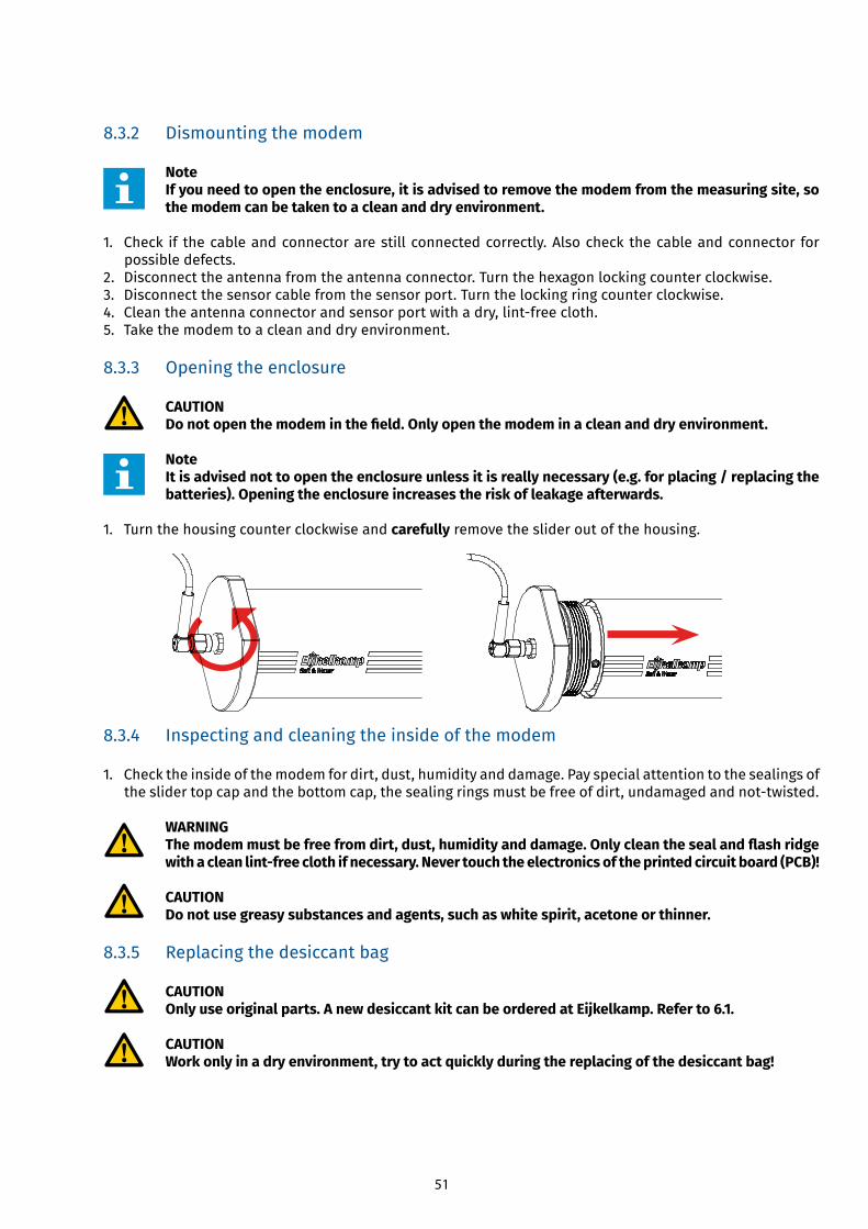
1. Turn the housing counter clockwise and carefully remove the slider out of the housing.
8.3.4 Inspecting and cleaning the inside of the modem
1. Check the inside of the modem for dirt, dust, humidity and damage. Pay special attention to the sealings of theslidertopcapandthebottomcap,thesealingringsmustbefreeofdirt,undamagedandnot-twisted.
WARNING The modem must be free from dirt, dust, humidity and damage. Only clean the seal and flash ridge with a clean lint-free cloth if necessary. Never touch the electronics of the printed circuit board (PCB)!
CAUTION Do not use greasy substances and agents, such as white spirit, acetone or thinner.
8.3.5 Replacing the desiccant bag
CAUTION Only use original parts. A new desiccant kit can be ordered at Eijkelkamp. Refer to 6.1.
CAUTION Work only in a dry environment, try to act quickly during the replacing of the desiccant bag!
52
1. Remove the old desiccant bag carefully and check whether this bag is excessively wet. If this is the case, this could be an indication of leakage. Please contact Eijkelkamp Soil & Water service department.
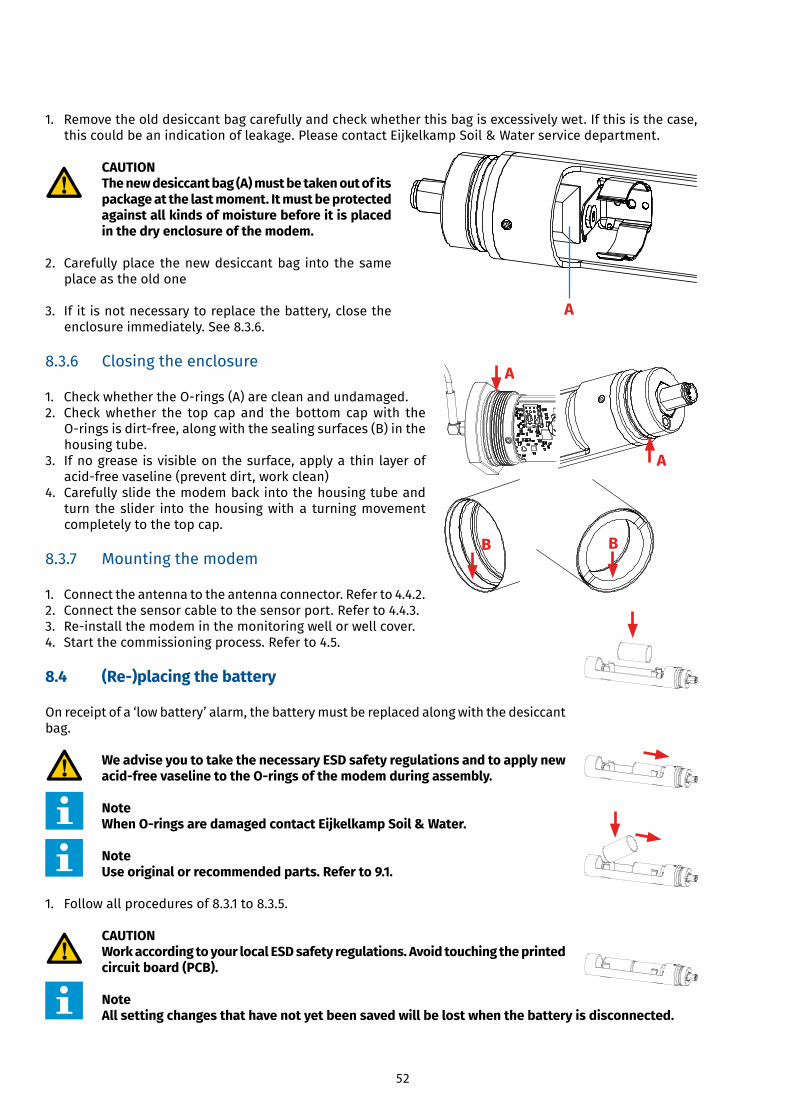
CAUTION The new desiccant bag (A) must be taken out of its package at the last moment. It must be protected against all kinds of moisture before it is placed in the dry enclosure of the modem.
2. Carefully place the new desiccant bag into the same place as the old one
3. If it is not necessary to replace the battery, close the enclosure immediately. See 8.3.6.
8.3.6 Closing the enclosure
1. CheckwhethertheO-rings(A)arecleanandundamaged.2. Check whether the top cap and the bottom cap with the
O-ringsisdirt-free,alongwiththesealingsurfaces(B)inthehousing tube.
3. If no grease is visible on the surface, apply a thin layer of acid-freevaseline(preventdirt,workclean)
4. Carefully slide the modem back into the housing tube and turn the slider into the housing with a turning movement completely to the top cap.
8.3.7 Mounting the modem
1. Connect the antenna to the antenna connector. Refer to 4.4.2. 2. Connect the sensor cable to the sensor port. Refer to 4.4.3. 3. Re-installthemodeminthemonitoringwellorwellcover.4. Start the commissioning process. Refer to 4.5.
8.4 (Re-)placing the battery
On receipt of a ‘low battery’ alarm, the battery must be replaced along with the desiccant bag.
We advise you to take the necessary ESD safety regulations and to apply new acid-free vaseline to the O-rings of the modem during assembly.
NoteWhen O-rings are damaged contact Eijkelkamp Soil & Water.
Note Use original or recommended parts. Refer to 9.1.
1. Follow all procedures of 8.3.1 to 8.3.5.
CAUTION Work according to your local ESD safety regulations. Avoid touching the printed circuit board (PCB).
Note All setting changes that have not yet been saved will be lost when the battery is disconnected.
A
A
A
B B
53
2. Carefully remove the empty battery. 3. Place the replacement battery pack.
CAUTION Prevent damage to the battery.
Note Make sure the battery is placed in the correct position.
Note When the battery is inserted into the modem: • The LED will briefly go on to indicate the modem is powered• The modem will behave as if the Start switch was magnetically activated• When this is not the case, check if the contacts from the battery holder are correctly placed to the contacts of the battery.• If necessary take out the battery and carefully bend the contacts and place the battery once again. When the new battery is placed you have to tell the modem that a new battery is installed. For an e-mail instruction use Supplement 2 or use the Eijkelkamp Web Portal for correct resetting the battery capacity used.
When placing two D cell alkaline batteries change to/check if the battery capacity max (µAh) is 10400000 µAh.When placing a DD cell lithium battery change to/check if the battery capacity max (µAh) is 28000000 µAh.
6. Follow all procedures of 8.3.6 to 8.3.7. 7. Dispose of the old battery in a proper way. Refer to 2.6.2.
8.5 (Re-)placing the SIM card (optional)
WARNINGDepending on the new SIM card the modem settings may need to be changed, therefore always contact Eijkelkamp Soil & Water first.
WARNING Always disconnect the battery before replacing the SIM card.
CAUTION Make sure that the PIN code of the SIM card is turned off or set to the desired PIN code.
Note If a PIN code is used, make sure that the PIN code that was configured in the modem is identical to the PIN code of the SIM card.
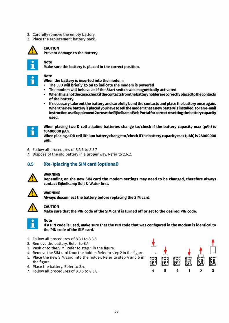
1. Follow all procedures of 8.3.1 to 8.3.5. 2. Remove the battery. Refer to 8.43. PushontotheSIM.Refertostep1inthefigure.4. RemovetheSIMcardfromtheholder.Refertostep2inthefigure.5. Place the new SIM card into the holder. Refer to step 4 and 5 in
thefigure.6. Place the battery. Refer to 8.4.7. Follow all procedures of 8.3.6 to 8.3.8. 14 5 6 32
54
8.6 Storage
CAUTION Do not place the modem in a humid and dusty environment. Do not place any heavy materials on top of the modem.
1. Clean the outside of the modem. Refer to 8.3.1. 2. Dismount the modem. Refer to 8.3.2. 3. Store the modem in a clean and dry place.
Note If a modem is not to be used for a longer period of time, it is important that the modem will be set in the power OFF mode via the Eijkelkamp Web Portal or e-mail functionality. Refer to the online manual on Eijkelkamp Web Portal or Supplement 2 on how to put the modem in the power OFF mode. In case the modem will not be used for a very long period of time, it is also advised to disconnect the battery. Even if the modem is in the power OFF mode, it actually continues to draw a minimum amount of current and thus drains the battery. However, it is also advised not to open the enclosure of the modem unless you really need to do so. Opening the enclosure increases the risk of leakage afterwards. Consider whether the battery needs to be removed or not. If the battery needs to be removed, refer to step 1 and 2 of 5.4.
9 Specifications
9.1 Parts list
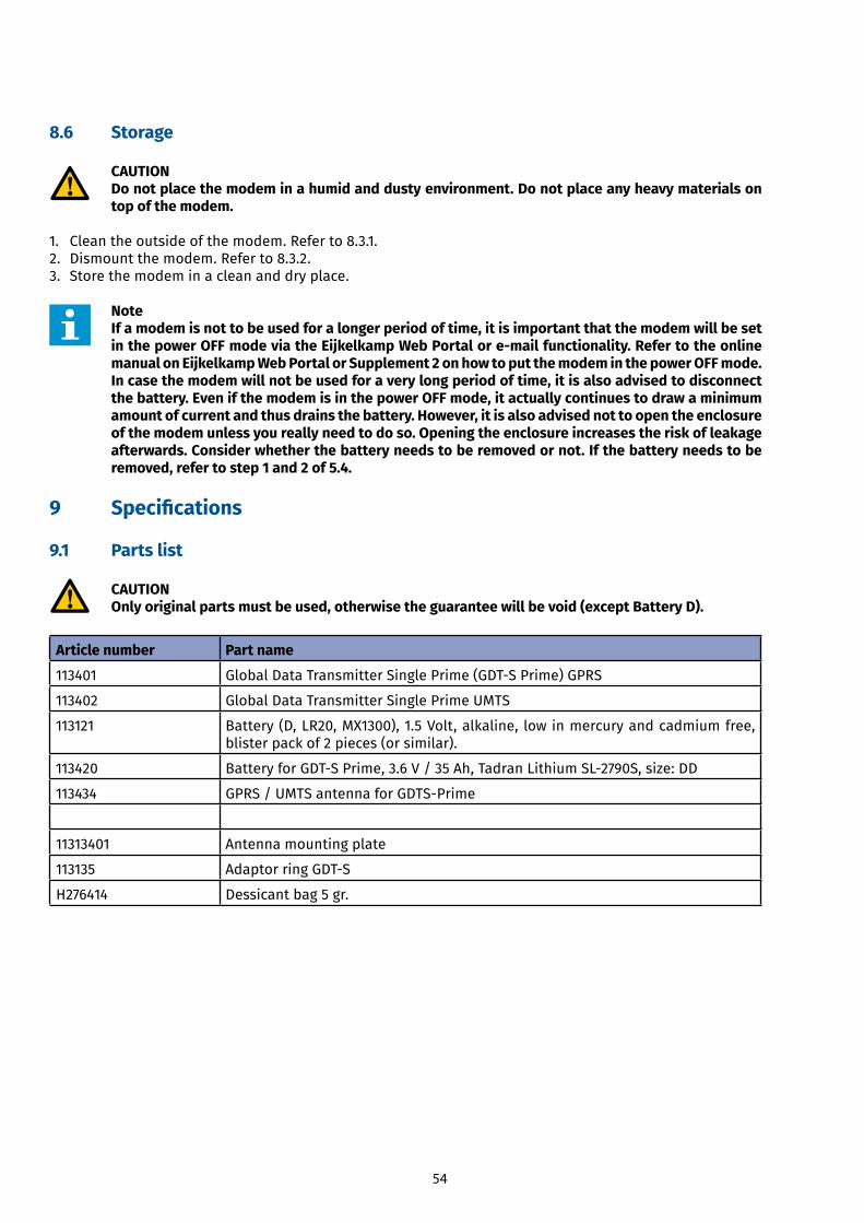
CAUTION Only original parts must be used, otherwise the guarantee will be void (except Battery D).
Article number Part name
113401 GlobalDataTransmitterSinglePrime(GDT-SPrime)GPRS
113402 Global Data Transmitter Single Prime UMTS
113121 Battery (D, LR20, MX1300), 1.5 Volt, alkaline, low in mercury and cadmium free, blister pack of 2 pieces (or similar).
113420 BatteryforGDT-SPrime,3.6V/35Ah,TadranLithiumSL-2790S,size:DD
113434 GPRS/UMTSantennaforGDTS-Prime
11313401 Antenna mounting plate
113135 AdaptorringGDT-S
H276414 Dessicant bag 5 gr.
Related Documents