GLC Detector Geometry Y. Sugimoto

GLC Detector Geometry Y. Sugimoto. Introduction Figure of merit : Main Tracker.
Dec 18, 2015
Welcome message from author
This document is posted to help you gain knowledge. Please leave a comment to let me know what you think about it! Share it to your friends and learn new things together.
Transcript
GLC Detector Geometry
Y. Sugimoto

Introduction
Figure of merit : Main Tracker
samplings ofNumber :
length Tracking :
field Magnetic :
resolution Spatial : 4
7203.3/ )( 2
2
n
L
B
nBLtp
tp

Figure of merit : Calorimeter jet
2 = ch2 +
2 + nh2 + confusion
2 + threashold2
Separation of charged particles and /nh is important (See J.C. Brient’s talk at LCWS2004)
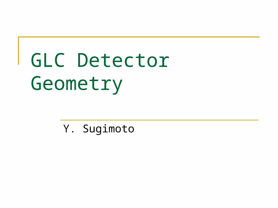
Charged particles should be spread out by B field Lateral size of EM shower of should be as small as possi
ble ( ~ Rmeffective: effective Moliere length)
Barrel: B Rin2/ Rm
effective
Endcap: B Z2/ Rmeffective
Rin : Inner radius of Barrel ECAL
Z : Z position of EC ECAL front face
(Actually, it is not so simple. Even with B=0, photon energy inside a certain distance from a charged track scales as ~R i
n2)

Simulation by J.C. Brient
SD (6T)
TESLA (4T)
e+e- ZH jets at Ecm=500GeV

Effective Moliere Length
Absorber W : Rm ~ 9mm Pb : Rm ~ 16mm
Gap : Sensor + R.O. elec + etc.
xa xg
Effective Molire Length = Rm (1+xg/xa)
B=0

Comparison of Detector Models
SD TESLA GLC LD JLC
Solenoid B(T) 5 4 3 3 2
Rin(m) 2.48 3.0 3.75 3.7 4.25
L(m) 5.8 9.2 6.8 9.4 9.1
Est(GJ) 1.4 2.3 1.0 1.7 1.1
Tracker Rmin (m) 0.2 0.36 0.45 0.5 0.45
Rmax(m) 1.25 1.62 1.55 2.0 2.3
m 7 150 85 150 100
Nsample 5 200 50 144 100
pt/pt2 3.9e-5 1.5e-4 2.9e-4 1.6e-4 1.3e-4

Comparison of Detector Models
SD TESLA GLC LD JLC
ECAL Rin(m) 1.27 1.68 1.6 2.0 2.5
ptmin 1.9 2.0 1.4 1.8 1.5
BRin2 8.1 11.3 7.7 12.0 12.5
Type W/Si W/Si Pb/Sci Pb/Sci Pb/Sci
Rm(mm) 18 24.4 25.5 21.3 21.3
BRin2/Rm 448 462 301 565 588
Z 1.72 2.83 2.05 3.0 2.9
BZ2/Rm 822 1311 494 1271 792
X0 21 24 27 29 29
Total 5.5 5.2 7.3 6.9 6.9
t (m) 1.18 1.3 1.8 1.7 1.5

Possible modification of GLC Detector Larger Rmax of the tracker and Rin of ECAL Keep solenoid radius same: Somewhat thinner CAL (but still 6), but does it matter? Use W/Sci(/Si) instead of Pb/Sci for ECAL
Effective Rm: 25.5mm 16.2mm (2.5mm W / 2.0mm Gap) Much smaller segmentation by Si pad layers
Put ECCAL at larger Z Longer Solenoid Preferable for B-field uniformity if TPC is used
If l*=4.3 (3.5) m is adopted, 10 cm thick W shield around the support tube is not necessary
Rmin of the tracker can be reduced It is preferable Zpole-tip < l* both for neutron b.g. and QC support

GLC B-field non-uniformity
mm
Z (m)
TESLA TDR Limit
R=0.1m
R=2.0m
TESLA TDR Limit: mm 2max
0
dzBz
Brz
by H.Yamaoka
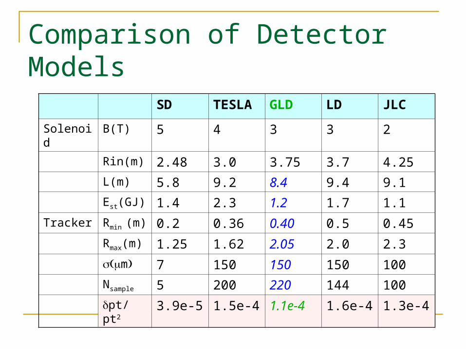
Comparison of Detector Models
SD TESLA GLD LD JLC
Solenoid B(T) 5 4 3 3 2
Rin(m) 2.48 3.0 3.75 3.7 4.25
L(m) 5.8 9.2 8.4 9.4 9.1
Est(GJ) 1.4 2.3 1.2 1.7 1.1
Tracker Rmin (m) 0.2 0.36 0.40 0.5 0.45
Rmax(m) 1.25 1.62 2.05 2.0 2.3
m 7 150 150 150 100
Nsample 5 200 220 144 100
pt/pt2 3.9e-5 1.5e-4 1.1e-4 1.6e-4 1.3e-4

Comparison of Detector Models
SD TESLA GLD LD JLC
ECAL Rin(m) 1.27 1.68 2.1 2.0 2.5
ptmin (GeV/c) 1.9 2.0 1.9 1.8 1.5
BRin2 8.1 11.3 13.2 12.0 12.5
Type W/Si W/Si W/Sci/Si Pb/Sci Pb/Sci
Rm(mm) 18 24.4 16.2 21.3 21.3
BRin2/Rm 448 462 817 565 588
Z 1.72 2.83 2.8 3.0 2.9
BZ2/Rm 822 1311 1452 1271 792
X0 21 24 27 29 29
Total 5.5 5.2 6.0 6.9 6.9
t (m) 1.18 1.3 1.4 1.7 1.5

EM Calorimeters
Area of EM CAL (Barrel + Endcap) SD: ~40 m2 / layer TESLA: ~80 m2 / layer GLD: ~ 100 m2 / layer (JLC: ~130 m2 / layer)

Global Geometry
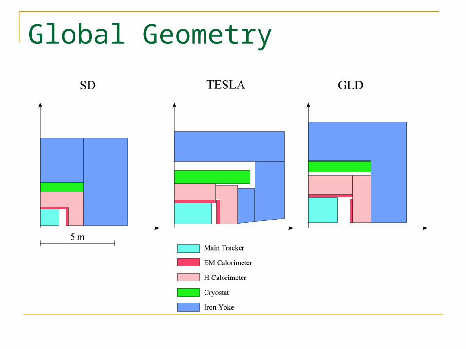
Global Geometry

Interaction Region
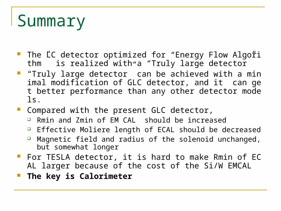
Summary
The LC detector optimized for “Energy Flow Algorithm” is realized with a “Truly large detector”
“Truly large detector” can be achieved with a minimal modification of GLC detector, and it can get better performance than any other detector models.
Compared with the present GLC detector, Rmin and Zmin of EM CAL should be increased Effective Moliere length of ECAL should be decreased Magnetic field and radius of the solenoid unchanged, but somewhat l
onger For TESLA detector, it is hard to make Rmin of ECAL larger bec
ause of the cost of the Si/W EMCAL The key is Calorimeter
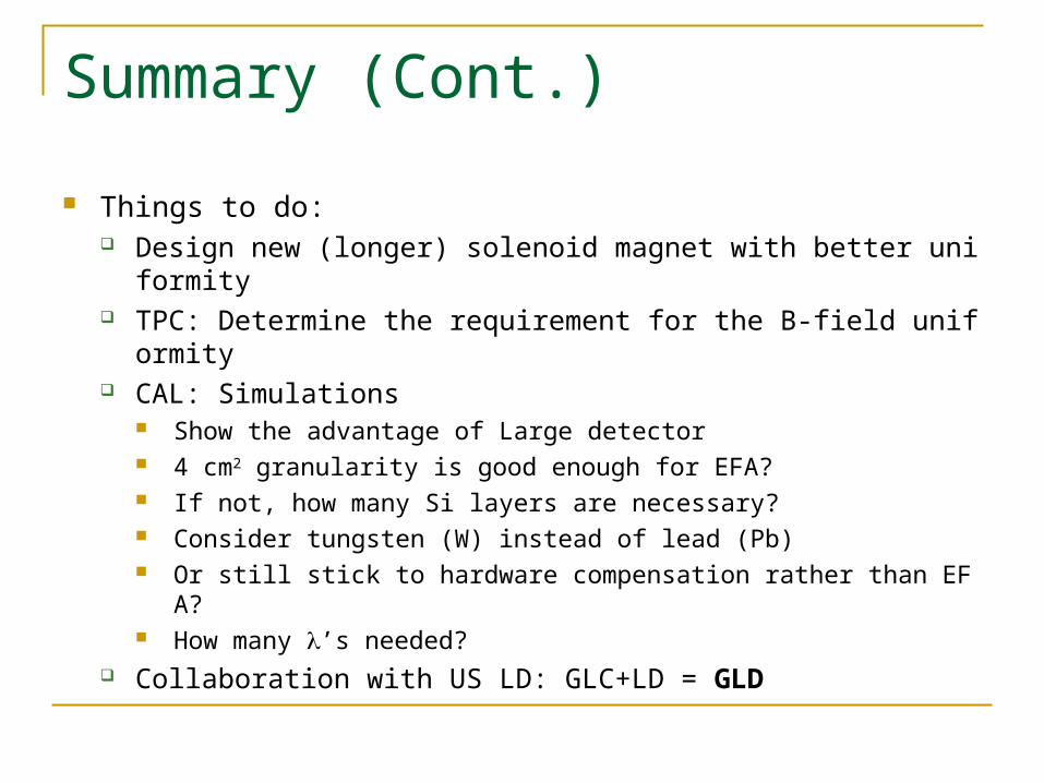
Summary (Cont.)
Things to do: Design new (longer) solenoid magnet with better uniformity TPC: Determine the requirement for the B-field uniformity CAL: Simulations
Show the advantage of Large detector 4 cm2 granularity is good enough for EFA? If not, how many Si layers are necessary? Consider tungsten (W) instead of lead (Pb) Or still stick to hardware compensation rather than EFA? How many ’s needed?
Collaboration with US LD: GLC+LD = GLD
Related Documents


![[HAVC] Fotografia: Hiroshi Sugimoto](https://static.cupdf.com/doc/110x72/558cde7dd8b42a155a8b4614/havc-fotografia-hiroshi-sugimoto.jpg)