GA-Z87-HD3 GA-H87-HD3 User's Manual Rev. 1002 12ME-Z87HD3-1002R

Gigabyte Motherboard
Nov 28, 2015
User Manual
Welcome message from author
This document is posted to help you gain knowledge. Please leave a comment to let me know what you think about it! Share it to your friends and learn new things together.
Transcript
GA-Z87-HD3GA-H87-HD3
User's ManualRev. 100212ME-Z87HD3-1002R

Motherboard
GA
-Z87-HD
3/GA
-H87-H
D3
Apr. 19, 2013
Apr. 19, 2013
Motherboard
GA
-Z87-HD
3/GA
-H87-H
D3
Copyright© 2013 GIGA-BYTE TECHNOLOGY CO., LTD. All rights reserved.The trademarks mentioned in this manual are legally registered to their respective owners.
DisclaimerInformation in this manual is protected by copyright laws and is the property of GIGABYTE.Changes to the specifications and features in this manual may be made by GIGABYTE without prior notice.
No part of this manual may be reproduced, copied, translated, transmitted, or published in any form or by any means without GIGABYTE's prior written permission.
Documentation ClassificationsIn order to assist in the use of this product, GIGABYTE provides the following types of docu-mentations:
� For quick set-up of the product, read the Quick Installation Guide included with the product. � For detailed product information, carefully read the User's Manual.
For product-related information, check on our website at: http://www.gigabyte.com
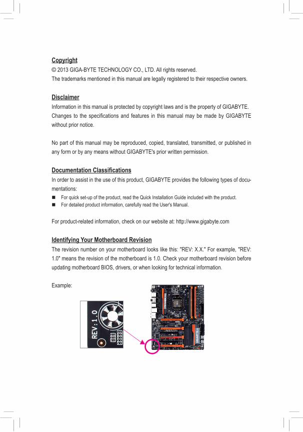
Identifying Your Motherboard RevisionThe revision number on your motherboard looks like this: "REV: X.X." For example, "REV: 1.0" means the revision of the motherboard is 1.0. Check your motherboard revision before updating motherboard BIOS, drivers, or when looking for technical information.
Example:
- 4 -
Table of Contents
Box Contents ...................................................................................................................6Optional Items .................................................................................................................6GA-Z87-HD3/GA-H87-HD3 Motherboard Layout ...........................................................7GA-Z87-HD3/GA-H87-HD3 Motherboard Block Diagram ...............................................8
Chapter 1 Hardware Installation .....................................................................................91-1 Installation Precautions ................................................................................... 91-2 ProductSpecifications ................................................................................... 101-3 Installing the CPU and CPU Cooler............................................................... 13
1-3-1 Installing the CPU ..................................................................................................131-3-2 Installing the CPU Cooler ......................................................................................15
1-4 Installing the Memory .................................................................................... 161-4-1 DualChannelMemoryConfiguration ....................................................................161-4-2 Installing a Memory ................................................................................................17
1-5 Installing an Expansion Card ......................................................................... 181-6 Back Panel Connectors ................................................................................. 191-7 Internal Connectors ....................................................................................... 21
Chapter 2 BIOS Setup ..................................................................................................312-1 Startup Screen ............................................................................................... 322-2 The Main Menu .............................................................................................. 332-3 M.I.T. .............................................................................................................. 352-4 System ........................................................................................................... 452-5 BIOS Features ............................................................................................... 462-6 Peripherals ..................................................................................................... 502-7 Power Management ....................................................................................... 542-8 Save & Exit .................................................................................................... 56
- 5 -
Chapter3 ConfiguringSATAHardDrive(s) ..................................................................573-1 ConfiguringSATAControllers ........................................................................ 573-2 Installing the SATA RAID/AHCI Driver and Operating System ..................... 69
Chapter 4 Drivers Installation .......................................................................................734-1 Chipset Drivers .............................................................................................. 734-2 Application Software ...................................................................................... 744-3 Information ..................................................................................................... 74
Chapter 5 Unique Features ...........................................................................................755-1 BIOS Update Utilities ..................................................................................... 75
5-1-1 Updating the BIOS with the Q-Flash Utility ...........................................................755-1-2 Updating the BIOS with the @BIOS Utility ............................................................78
5-2 APP Center .................................................................................................... 795-2-1 EasyTune ............................................................................................................... 805-2-2 EZ Setup ................................................................................................................815-2-3 USB Blocker .......................................................................................................... 86
Chapter 6 Appendix ......................................................................................................876-1 ConfiguringAudioInputandOutput .............................................................. 87
6-1-1 Configuring2/4/5.1/7.1-ChannelAudio ..................................................................876-1-2 ConfiguringS/PDIFOut ........................................................................................ 896-1-3 ConfiguringMicrophoneRecording ...................................................................... 896-1-4 Using the Sound Recorder ....................................................................................92
6-2 Troubleshooting ............................................................................................. 936-2-1 Frequently Asked Questions .................................................................................936-2-2 Troubleshooting Procedure .................................................................................. 94
Regulatory Statements ............................................................................................. 96Contact Us ................................................................................................................ 99
- 6 -
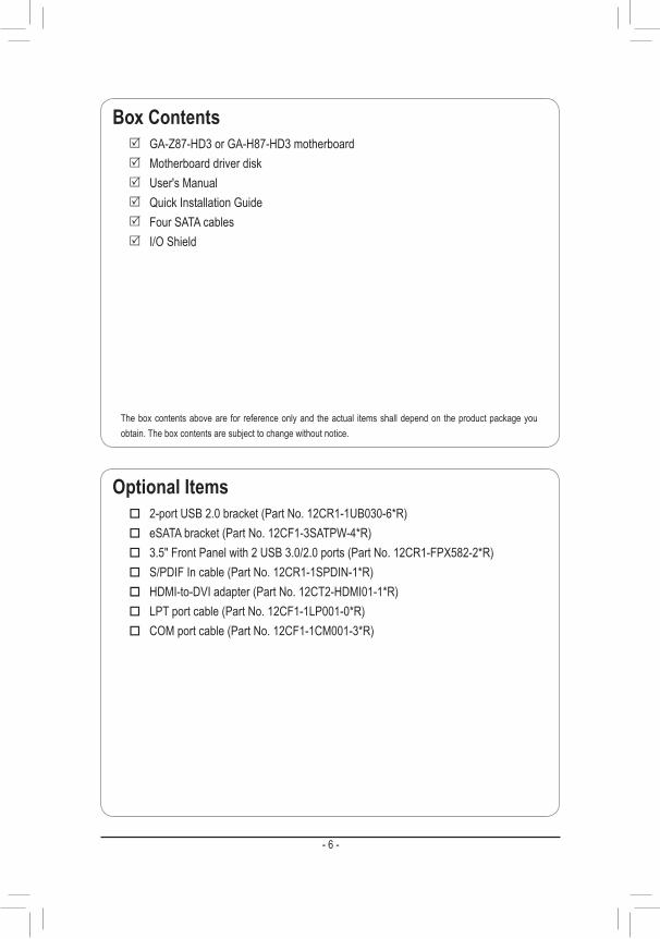
Optional Items � 2-portUSB2.0bracket(PartNo.12CR1-1UB030-6*R) � eSATAbracket(PartNo.12CF1-3SATPW-4*R) � 3.5"FrontPanelwith2USB3.0/2.0ports(PartNo.12CR1-FPX582-2*R) � S/PDIFIncable(PartNo.12CR1-1SPDIN-1*R) � HDMI-to-DVIadapter(PartNo.12CT2-HDMI01-1*R) � LPTportcable(PartNo.12CF1-1LP001-0*R) � COMportcable(PartNo.12CF1-1CM001-3*R)
The box contents above are for reference only and the actual items shall depend on the product package you obtain. The box contents are subject to change without notice.
Box Contents 5 GA-Z87-HD3 or GA-H87-HD3 motherboard 5 Motherboard driver disk 5 User's Manual 5 Quick Installation Guide 5 Four SATA cables 5 I/O Shield
- 7 -
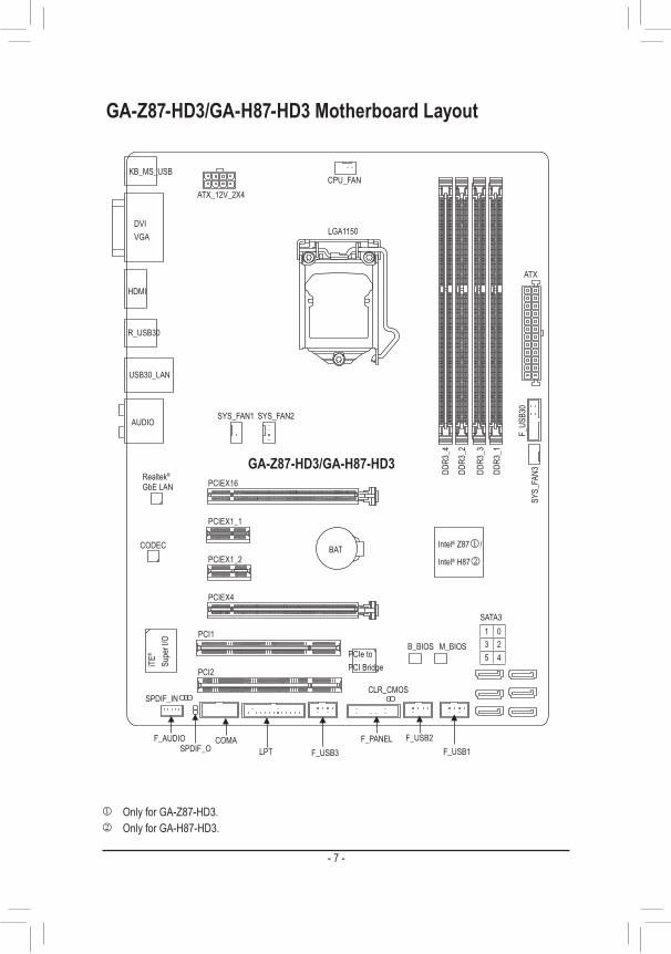
GA-Z87-HD3/GA-H87-HD3 Motherboard Layout
KB_MS_USBCPU_FAN
ATX_12V_2X4
ATX
F_AUDIO
AUDIO
B_BIOS
PCIEX4
DDR3
_2
DDR3
_1
DDR3
_4
DDR3
_3
BAT
F_PANELCOMA
Intel® Z87j/
Intel® H87k
PCI2
CLR_CMOS
CODEC
M_BIOS
PCIEX1_1
PCIEX16
SPDIF_O F_USB1
LGA1150
GA-Z87-HD3/GA-H87-HD3
DVI VGA
HDMI
R_USB30
USB30_LAN
Realtek®
GbELAN
PCI1
F_US
B30
PCIEX1_2
SYS_
FAN3
SATA3
iTE®
Supe
r I/O
SYS_FAN2
F_USB2LPT
1 03 25 4
j Only for GA-Z87-HD3.k Only for GA-H87-HD3.
SYS_FAN1
PCIe to PCI Bridge
F_USB3
SPDIF_IN
- 8 -
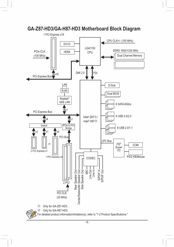
GA-Z87-HD3/GA-H87-HD3 Motherboard Block Diagram
PS/2 KB/Mouse
LGA1150CPU
DMI 2.0 FDI
CPUCLK+/-(100MHz)
Dual BIOS
DDR31600/1333MHzDual Channel Memory
COMLPC Bus
Intel® Z87j/Intel® H87k
iTE® Super
I/O
PCIe CLK(100MHz)
PCI Express Bus
1 PCI Express x16
x1
LAN
RJ45
Realtek®
GbELAN
2 PCI
PCI Bus
PCI CLK(33MHz)
PCIe to PCI Bridge
x1
PCI Express Bus
x16
D-Sub
6 SATA 6Gb/s
j Only for GA-Z87-HD3.k Only for GA-H87-HD3.
DVI-D
HDMI
8 USB 2.0/1.1
6 USB 3.0/2.0
Fordetailedproductinformation/limitation(s),referto"1-2ProductSpecifications."
Cente
r/Sub
woofe
r Spe
aker
Out
Line O
utMI
C
Line I
n
S/PD
IF O
utS/
PDIF
In
Side
Spe
aker
Out
Rear
Spe
aker
Out
CODEC
x1
2 PCI Express x1
x4
1 PCI Express x4
Switch
or
x4x1
- 9 - Hardware Installation
1-1 Installation PrecautionsThe motherboard contains numerous delicate electronic circuits and components which can become damagedasaresultofelectrostaticdischarge(ESD).Priortoinstallation,carefullyreadtheuser'smanual and follow these procedures:
• Prior to installation, make sure the chassis is suitable for the motherboard. • Prior to installation, donot removeor breakmotherboardS/N (SerialNumber) sticker or
warranty sticker provided by your dealer. These stickers are required for warranty validation. • Always remove the AC power by unplugging the power cord from the power outlet before
installing or removing the motherboard or other hardware components. • Whenconnectinghardwarecomponentstotheinternalconnectorsonthemotherboard,make
sure they are connected tightly and securely. • Whenhandlingthemotherboard,avoidtouchinganymetalleadsorconnectors. • It is best towear an electrostatic discharge (ESD)wrist strapwhen handling electronic
components such as a motherboard, CPU or memory. If you do not have an ESD wrist strap, keepyourhandsdryandfirsttouchametalobjecttoeliminatestaticelectricity.
• Prior to installing the motherboard, please have it on top of an antistatic pad or within an electrostatic shielding container.
• Before unplugging the power supply cable from the motherboard, make sure the power supply has been turned off.
• Before turning on the power, make sure the power supply voltage has been set according to the local voltage standard.
• Before using the product, please verify that all cables and power connectors of your hardware components are connected.
• To prevent damage to the motherboard, do not allow screws to come in contact with the motherboard circuit or its components.
• Make sure there are no leftover screws or metal components placed on the motherboard or within the computer casing.
• Do not place the computer system on an uneven surface. • Do not place the computer system in a high-temperature environment. • Turning on the computer power during the installation process can lead to damage to system
components as well as physical harm to the user. • If you are uncertain about any installation steps or have a problem related to the use of the product,pleaseconsultacertifiedcomputertechnician.
Chapter 1 Hardware Installation
- 10 -Hardware Installation
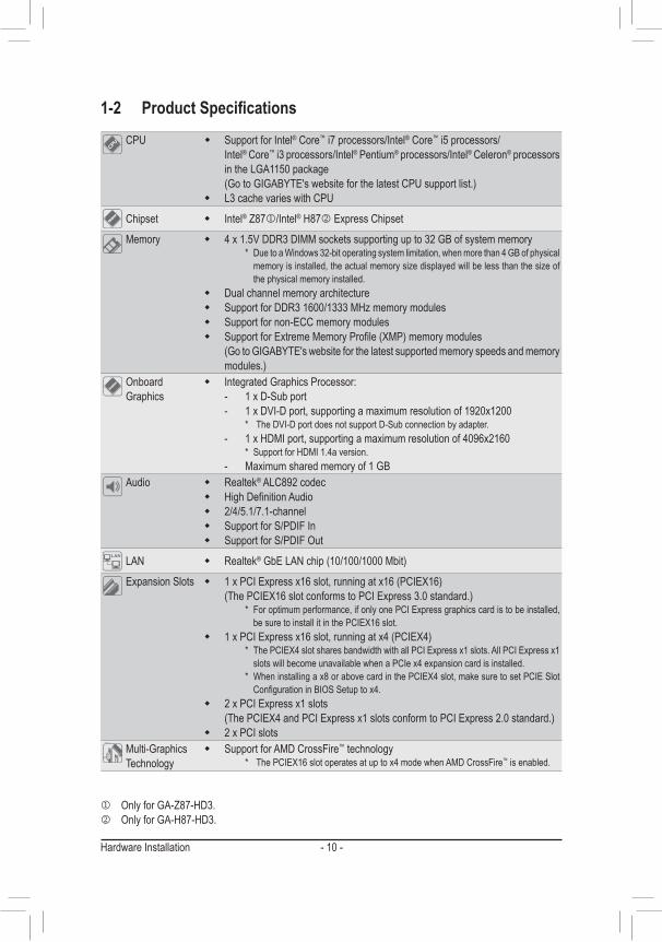
1-2 ProductSpecificationsCPU � Support for Intel® Core™ i7 processors/Intel® Core™ i5 processors/
Intel® Core™ i3 processors/Intel® Pentium® processors/Intel® Celeron® processors in the LGA1150 package(GotoGIGABYTE'swebsiteforthelatestCPUsupportlist.)
� L3 cache varies with CPU
Chipset � Intel® Z87j/Intel® H87k Express Chipset
Memory � 4 x 1.5V DDR3 DIMM sockets supporting up to 32 GB of system memory * DuetoaWindows32-bitoperatingsystemlimitation,whenmorethan4GBofphysical
memoryisinstalled,theactualmemorysizedisplayedwillbelessthanthesizeofthe physical memory installed.
� Dual channel memory architecture � SupportforDDR31600/1333MHzmemorymodules � Support for non-ECC memory modules � SupportforExtremeMemoryProfile(XMP)memorymodules
(GotoGIGABYTE'swebsiteforthelatestsupportedmemoryspeedsandmemorymodules.)
Onboard Graphics
� Integrated Graphics Processor: - 1 x D-Sub port - 1 x DVI-D port, supporting a maximum resolution of 1920x1200 * TheDVI-DportdoesnotsupportD-Subconnectionbyadapter. - 1 x HDMI port, supporting a maximum resolution of 4096x2160
* SupportforHDMI1.4aversion.- Maximum shared memory of 1 GB
Audio � Realtek® ALC892 codec � HighDefinitionAudio � 2/4/5.1/7.1-channel � Support for S/PDIF In � Support for S/PDIF Out
LAN � Realtek®GbELANchip(10/100/1000Mbit)
Expansion Slots � 1xPCIExpressx16slot,runningatx16(PCIEX16) (ThePCIEX16slotconformstoPCIExpress3.0standard.) * Foroptimumperformance,ifonlyonePCIExpressgraphicscardistobeinstalled,
besuretoinstallitinthePCIEX16slot. � 1xPCIExpressx16slot,runningatx4(PCIEX4)
* ThePCIEX4slotsharesbandwidthwithallPCIExpressx1slots.AllPCIExpressx1slots will become unavailable when a PCIe x4 expansion card is installed.
* Wheninstallingax8orabovecardinthePCIEX4slot,makesuretosetPCIESlotConfigurationinBIOSSetuptox4.
� 2 x PCI Express x1 slots (ThePCIEX4andPCIExpressx1slotsconformtoPCIExpress2.0standard.)
� 2 x PCI slotsMulti-Graphics Technology
� Support for AMD CrossFire™ technology * ThePCIEX16slotoperatesatuptox4modewhenAMDCrossFire™ is enabled.
j Only for GA-Z87-HD3.k Only for GA-H87-HD3.
- 11 - Hardware Installation
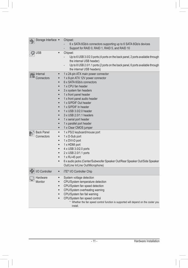
Storage Interface � Chipset: - 6 x SATA 6Gb/s connectors supporting up to 6 SATA 6Gb/s devices - Support for RAID 0, RAID 1, RAID 5, and RAID 10
USB � Chipset: - Upto6USB3.0/2.0ports(4portsonthebackpanel,2portsavailablethrough
theinternalUSBheader) - Upto8USB2.0/1.1ports(2portsonthebackpanel,6portsavailablethrough
theinternalUSBheaders)Internal Connectors
� 1x24-pinATXmainpowerconnector � 1x8-pinATX12Vpowerconnector � 6 x SATA 6Gb/s connectors � 1 x CPU fan header � 3 x system fan headers � 1 x front panel header � 1 x front panel audio header � 1 x S/PDIF Out header � 1 x S/PDIF In header � 1 x USB 3.0/2.0 header � 3 x USB 2.0/1.1 headers � 1 x serial port header � 1 x parallel port header � 1 x Clear CMOS jumper
Back Panel Connectors
� 1 x PS/2 keyboard/mouse port � 1 x D-Sub port � 1 x DVI-D port � 1 x HDMI port � 4 x USB 3.0/2.0 ports � 2 x USB 2.0/1.1 ports � 1 x RJ-45 port � 6xaudiojacks(Center/SubwooferSpeakerOut/RearSpeakerOut/SideSpeaker
Out/LineIn/LineOut/Microphone)
I/O Controller � iTE® I/O Controller Chip
Hardware Monitor
� System voltage detection � CPU/System temperature detection � CPU/System fan speed detection � CPU/System overheating warning � CPU/System fan fail warning � CPU/System fan speed control
* Whetherthefanspeedcontrolfunctionissupportedwilldependonthecooleryouinstall.
- 12 -Hardware Installation
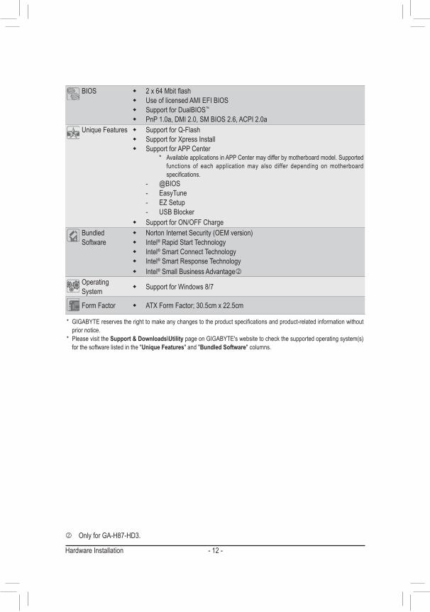
BIOS � 2x64Mbitflash � Use of licensed AMI EFI BIOS � Support for DualBIOS™
� PnP 1.0a, DMI 2.0, SM BIOS 2.6, ACPI 2.0aUnique Features � Support for Q-Flash
� SupportforXpressInstall � Support for APP Center
* AvailableapplicationsinAPPCentermaydifferbymotherboardmodel.Supportedfunctions of each application may also differ depending on motherboard specifications.
- @BIOS- EasyTune- EZ Setup- USB Blocker
� Support for ON/OFFChargeBundled Software
� NortonInternetSecurity(OEMversion) � Intel® Rapid Start Technology � Intel® Smart Connect Technology � Intel® Smart Response Technology � Intel® Small Business Advantagek
Operating System � SupportforWindows8/7
Form Factor � ATXFormFactor;30.5cmx22.5cm
* GIGABYTEreservestherighttomakeanychangestotheproductspecificationsandproduct-relatedinformationwithoutprior notice.
* PleasevisittheSupport & Downloads\UtilitypageonGIGABYTE'swebsitetocheckthesupportedoperatingsystem(s)for the software listed in the "Unique Features" and "Bundled Software" columns.
k Only for GA-H87-HD3.
- 13 - Hardware Installation
1-3 Installing the CPU and CPU CoolerRead the following guidelines before you begin to install the CPU: • Make sure that the motherboard supports the CPU. (GotoGIGABYTE'swebsiteforthelatestCPUsupportlist.) • Always turn off the computer and unplug the power cord from the power outlet before installing the
CPU to prevent hardware damage. • LocatethepinoneoftheCPU.TheCPUcannotbeinsertediforientedincorrectly.(OryoumaylocatethenotchesonbothsidesoftheCPUandalignmentkeysontheCPUsocket.)
• Apply an even and thin layer of thermal grease on the surface of the CPU. • Do not turn on the computer if the CPU cooler is not installed, otherwise overheating and damage
of the CPU may occur. • SettheCPUhostfrequencyinaccordancewiththeCPUspecifications.Itisnotrecommendedthatthesystembusfrequencybesetbeyondhardwarespecificationssinceitdoesnotmeetthestandard requirements for the peripherals. If you wish to set the frequency beyond the standard specifications,pleasedosoaccordingtoyourhardwarespecificationsincludingtheCPU,graphicscard, memory, hard drive, etc.
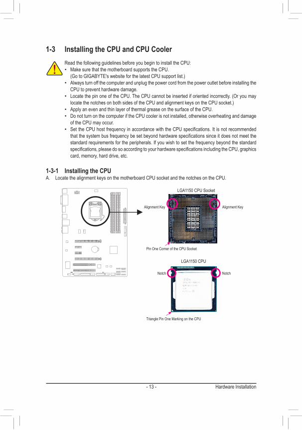
1-3-1 Installing the CPUA. Locate the alignment keys on the motherboard CPU socket and the notches on the CPU.
Notch
Alignment KeyAlignment Key
Notch
LGA1150 CPU
LGA1150 CPU Socket
Pin One Corner of the CPU Socket
Triangle Pin One Marking on the CPU
- 14 -Hardware Installation
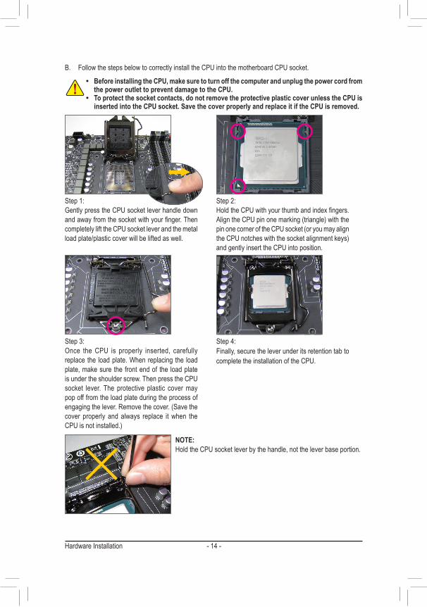
B. Follow the steps below to correctly install the CPU into the motherboard CPU socket.
Step 1:Gently press the CPU socket lever handle down andawayfromthesocketwithyourfinger.Thencompletely lift the CPU socket lever and the metal load plate/plastic cover will be lifted as well.
Step 2:HoldtheCPUwithyourthumbandindexfingers.AligntheCPUpinonemarking(triangle)withthepinonecorneroftheCPUsocket(oryoumayaligntheCPUnotcheswiththesocketalignmentkeys)and gently insert the CPU into position.
Step 4:Finally, secure the lever under its retention tab to complete the installation of the CPU.
NOTE:Hold the CPU socket lever by the handle, not the lever base portion.
• Before installing the CPU, make sure to turn off the computer and unplug the power cord from the power outlet to prevent damage to the CPU.
• To protect the socket contacts, do not remove the protective plastic cover unless the CPU is inserted into the CPU socket. Save the cover properly and replace it if the CPU is removed.
Step 3:Once the CPU is properly inserted, carefully replacethe loadplate.Whenreplacing the loadplate, make sure the front end of the load plate is under the shoulder screw. Then press the CPU socket lever. The protective plastic cover may pop off from the load plate during the process of engagingthelever.Removethecover.(Savethecover properly and always replace it when the CPUisnotinstalled.)

- 15 - Hardware Installation
1-3-2 Installing the CPU CoolerFollowthestepsbelowtocorrectlyinstalltheCPUcooleronthemotherboard.(ThefollowingprocedureusesIntel®boxedcoolerastheexamplecooler.)
Use extreme care when removing the CPU cooler because the thermal grease/tape between the CPU cooler and CPU may adhere to the CPU. Inadequately removing the CPU cooler may damage the CPU.
Step 5:After the installation, check the back of the motherboard. If the push pin is inserted as the picture above shows, the installation is complete.
Step 6:Finally, attach the power connector of the CPU coolertotheCPUfanheader(CPU_FAN)onthemotherboard.
Step 1:Apply an even and thin layer of thermal grease on the surface of the installed CPU.
Step 2:Before installing the cooler, note the direction of the arrow sign onthemalepushpin.(Turningthepush pin along the direction of arrow is to remove thecooler,onthecontrary,istoinstall.)
Step 3:Place the cooler atop the CPU, aligning the four push pins through the pin holes on the motherboard. Push down on the push pins diagonally.
Step 4:You should hear a "click" when pushing down each push pin. Check that the Male and Female push pins are joined closely.(RefertoyourCPUcoolerinstallationmanualforinstructionsoninstallingthecooler.)
Male Push Pin
Female Push Pin
The Top of Female Push Pin
Direction of the Arrow Sign on the Male Push Pin
- 16 -Hardware Installation
1-4 Installing the MemoryRead the following guidelines before you begin to install the memory: • Make sure that the motherboard supports the memory. It is recommended that memory of the same
capacity, brand, speed, and chips be used. (GotoGIGABYTE'swebsiteforthelatestsupportedmemoryspeedsandmemorymodules.) • Always turn off the computer and unplug the power cord from the power outlet before installing the
memory to prevent hardware damage. • Memory modules have a foolproof design. A memory module can be installed in only one direction.
If you are unable to insert the memory, switch the direction.
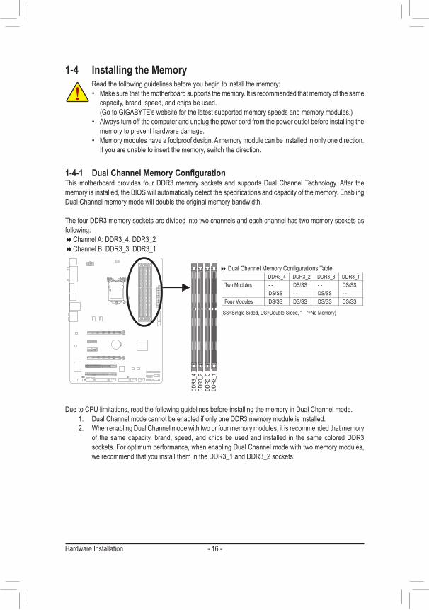
� DualChannelMemoryConfigurationsTable:
(SS=Single-Sided,DS=Double-Sided,"--"=NoMemory)
1-4-1 DualChannelMemoryConfigurationThis motherboard provides four DDR3 memory sockets and supports Dual Channel Technology. After the memoryisinstalled,theBIOSwillautomaticallydetectthespecificationsandcapacityofthememory.EnablingDual Channel memory mode will double the original memory bandwidth.
The four DDR3 memory sockets are divided into two channels and each channel has two memory sockets as following:
�Channel A: DDR3_4, DDR3_2 �Channel B: DDR3_3, DDR3_1
DDR3
_4DD
R3_2
DDR3
_3DD
R3_1
Due to CPU limitations, read the following guidelines before installing the memory in Dual Channel mode.1. Dual Channel mode cannot be enabled if only one DDR3 memory module is installed.2. WhenenablingDualChannelmodewithtwoorfourmemorymodules,itisrecommendedthatmemory
of the same capacity, brand, speed, and chips be used and installed in the same colored DDR3 sockets. For optimum performance, when enabling Dual Channel mode with two memory modules, we recommend that you install them in the DDR3_1 and DDR3_2 sockets.
DDR3_4 DDR3_2 DDR3_3 DDR3_1Two Modules - - DS/SS - - DS/SS
DS/SS - - DS/SS - -Four Modules DS/SS DS/SS DS/SS DS/SS
- 17 - Hardware Installation
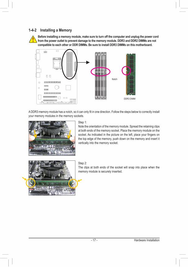
1-4-2 Installing a MemoryBefore installing a memory module, make sure to turn off the computer and unplug the power cord from the power outlet to prevent damage to the memory module. DDR3 and DDR2 DIMMs are not compatible to each other or DDR DIMMs. Be sure to install DDR3 DIMMs on this motherboard.
Notch
DDR3 DIMM
ADDR3memorymodulehasanotch,soitcanonlyfitinonedirection.Followthestepsbelowtocorrectlyinstallyour memory modules in the memory sockets.
Step 1:Notetheorientationofthememorymodule.Spreadtheretainingclipsat both ends of the memory socket. Place the memory module on the socket.Asindicatedinthepictureontheleft,placeyourfingersonthe top edge of the memory, push down on the memory and insert it vertically into the memory socket.
Step 2:The clips at both ends of the socket will snap into place when the memory module is securely inserted.
- 18 -Hardware Installation
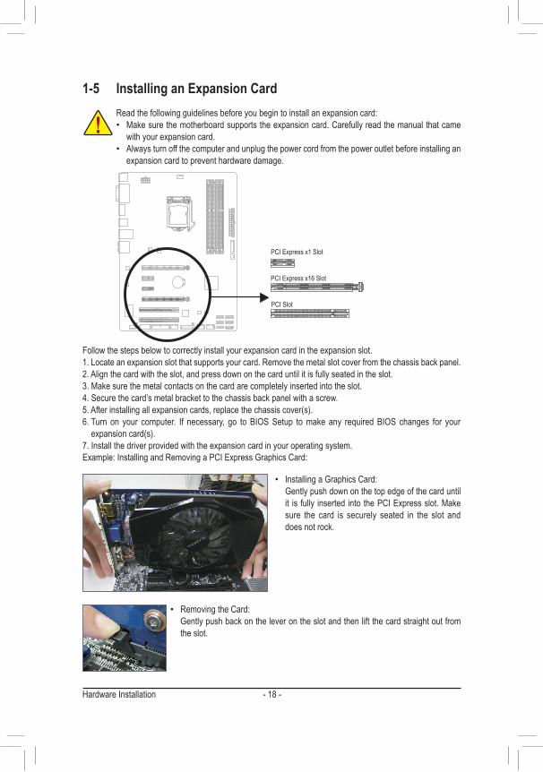
1-5 Installing an Expansion CardRead the following guidelines before you begin to install an expansion card: • Make sure the motherboard supports the expansion card. Carefully read the manual that came
with your expansion card. • Always turn off the computer and unplug the power cord from the power outlet before installing an
expansion card to prevent hardware damage.
Follow the steps below to correctly install your expansion card in the expansion slot.1. Locate an expansion slot that supports your card. Remove the metal slot cover from the chassis back panel.2. Align the card with the slot, and press down on the card until it is fully seated in the slot.3. Make sure the metal contacts on the card are completely inserted into the slot.4. Secure the card’s metal bracket to the chassis back panel with a screw.5.Afterinstallingallexpansioncards,replacethechassiscover(s).6. Turn on your computer. If necessary, go to BIOS Setup to make any required BIOS changes for your expansioncard(s).
7. Install the driver provided with the expansion card in your operating system.Example: Installing and Removing a PCI Express Graphics Card:
PCI Express x1 Slot
PCI Express x16 Slot
PCI Slot
• Installing a Graphics Card:Gently push down on the top edge of the card until it is fully inserted into the PCI Express slot. Make sure the card is securely seated in the slot and does not rock.
• Removing the Card:Gently push back on the lever on the slot and then lift the card straight out from the slot.
- 19 - Hardware Installation
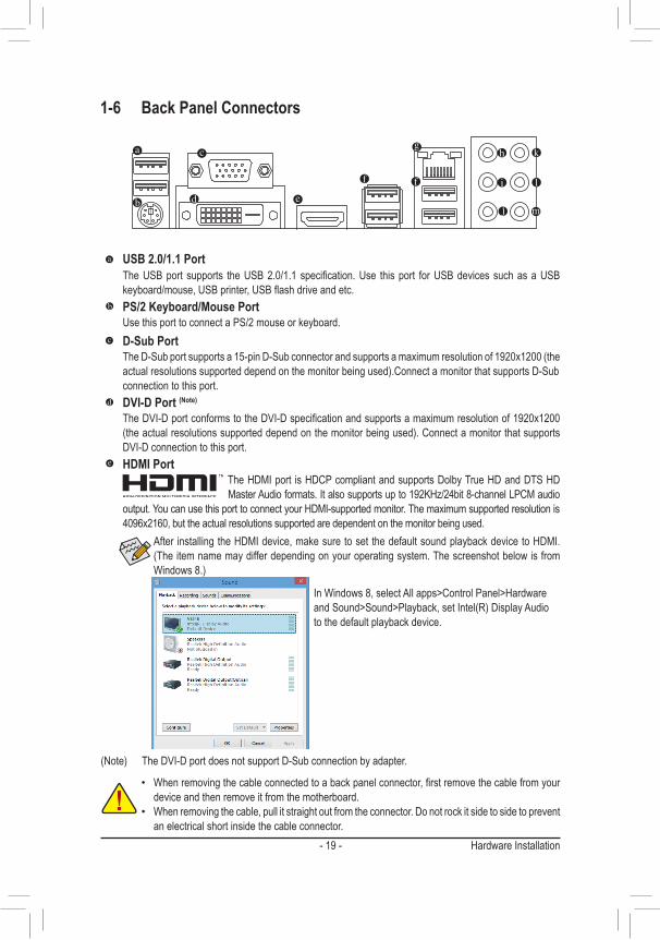
1-6 Back Panel Connectors
USB 2.0/1.1 PortTheUSBport supports theUSB2.0/1.1specification.Use thisport forUSBdevicessuchasaUSBkeyboard/mouse,USBprinter,USBflashdriveandetc.PS/2 Keyboard/Mouse PortUse this port to connect a PS/2 mouse or keyboard.D-Sub PortTheD-Subportsupportsa15-pinD-Subconnectorandsupportsamaximumresolutionof1920x1200(theactualresolutionssupporteddependonthemonitorbeingused).ConnectamonitorthatsupportsD-Subconnection to this port.DVI-D Port (Note)
TheDVI-DportconformstotheDVI-Dspecificationandsupportsamaximumresolutionof1920x1200(theactualresolutionssupporteddependonthemonitorbeingused).ConnectamonitorthatsupportsDVI-D connection to this port.HDMI Port
The HDMI port is HDCP compliant and supports Dolby True HD and DTS HD MasterAudioformats.Italsosupportsupto192KHz/24bit8-channelLPCMaudio
output. You can use this port to connect your HDMI-supported monitor. The maximum supported resolution is 4096x2160, but the actual resolutions supported are dependent on the monitor being used.
(Note) TheDVI-DportdoesnotsupportD-Subconnectionbyadapter.
After installing the HDMI device, make sure to set the default sound playback device to HDMI. (Theitemnamemaydifferdependingonyouroperatingsystem.ThescreenshotbelowisfromWindows8.)
InWindows8,selectAllapps>ControlPanel>HardwareandSound>Sound>Playback,setIntel(R)DisplayAudioto the default playback device.
• Whenremovingthecableconnectedtoabackpanelconnector,firstremovethecablefromyourdevice and then remove it from the motherboard.
• Whenremovingthecable,pullitstraightoutfromtheconnector.Donotrockitsidetosidetopreventan electrical short inside the cable connector.
- 20 -Hardware Installation
Center/Subwoofer Speaker Out Jack (Orange)Usethisaudiojacktoconnectcenter/subwooferspeakersina5.1/7.1-channelaudioconfiguration.Rear Speaker Out Jack (Black)Thisjackcanbeusedtoconnectfrontspeakersina4/5.1/7.1-channelaudioconfiguration.Side Speaker Out Jack (Gray)Usethisaudiojacktoconnectsidespeakersina7.1-channelaudioconfiguration.Line In Jack (Blue)The default line in jack. Use this audio jack for line in devices such as an optical drive, walkman, etc.Line Out Jack (Green)The default line out jack. Use this audio jack for a headphone or 2-channel speaker. This jack can be used toconnectfrontspeakersina4/5.1/7.1-channelaudioconfiguration.Mic In Jack (Pink)The default Mic in jack. Microphones must be connected to this jack.
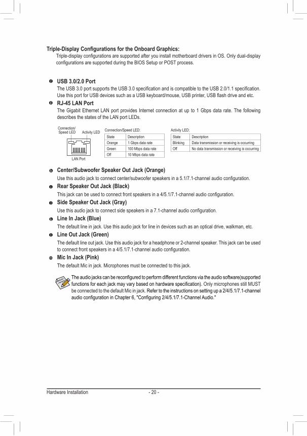
Activity LEDConnection/Speed LED
LANPort
Activity LED:Connection/Speed LED:State DescriptionOrange 1 Gbps data rateGreen 100 Mbps data rateOff 10 Mbps data rate
State DescriptionBlinking Data transmission or receiving is occurringOff Nodatatransmissionorreceivingisoccurring
USB 3.0/2.0 PortTheUSB3.0portsupportstheUSB3.0specificationandiscompatibletotheUSB2.0/1.1specification.UsethisportforUSBdevicessuchasaUSBkeyboard/mouse,USBprinter,USBflashdriveandetc.RJ-45 LAN PortTheGigabitEthernetLANportprovides Internetconnectionatup to1Gbpsdata rate.The followingdescribesthestatesoftheLANportLEDs.
Triple-DisplayConfigurationsfortheOnboardGraphics: Triple-displayconfigurationsaresupportedafteryouinstallmotherboarddriversinOS.Onlydual-display
configurationsaresupportedduringtheBIOSSetuporPOSTprocess.
Theaudiojackscanbereconfiguredtoperformdifferentfunctionsviatheaudiosoftware(supportedfunctionsforeachjackmayvarybasedonhardwarespecification). Only microphones still MUST be connected to the default Mic in jack. Refer to the instructions on setting up a 2/4/5.1/7.1-channel audioconfigurationinChapter6,"Configuring2/4/5.1/7.1-ChannelAudio."
- 21 - Hardware Installation
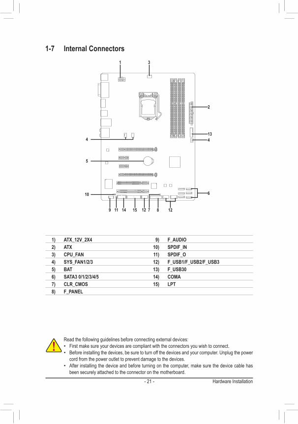
1-7 Internal Connectors
Read the following guidelines before connecting external devices: • First make sure your devices are compliant with the connectors you wish to connect. • Before installing the devices, be sure to turn off the devices and your computer. Unplug the power
cord from the power outlet to prevent damage to the devices. • After installing the device and before turning on the computer, make sure the device cable has
been securely attached to the connector on the motherboard.
13
1
4
2
1211
5
9 7
3
6
8
10
1) ATX_12V_2X42) ATX3) CPU_FAN4) SYS_FAN1/2/35) BAT6) SATA3 0/1/2/3/4/57) CLR_CMOS8) F_PANEL
9) F_AUDIO10) SPDIF_IN11) SPDIF_O12) F_USB1/F_USB2/F_USB313) F_USB3014) COMA15) LPT
14 15
4
12
- 22 -Hardware Installation
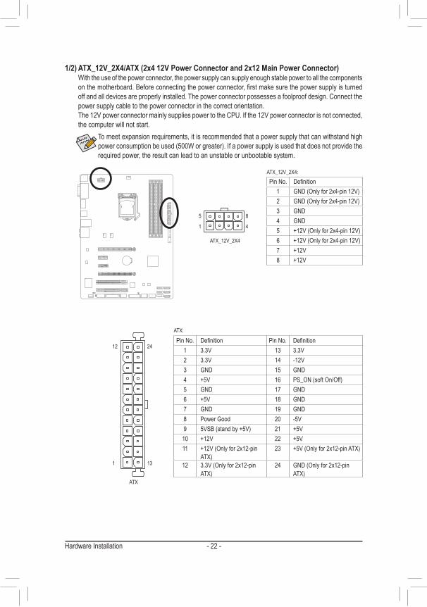
1/2) ATX_12V_2X4/ATX (2x4 12V Power Connector and 2x12 Main Power Connector) Withtheuseofthepowerconnector,thepowersupplycansupplyenoughstablepowertoallthecomponents
onthemotherboard.Beforeconnectingthepowerconnector,firstmakesurethepowersupplyisturnedoff and all devices are properly installed. The power connector possesses a foolproof design. Connect the power supply cable to the power connector in the correct orientation.
The 12V power connector mainly supplies power to the CPU. If the 12V power connector is not connected, the computer will not start.
To meet expansion requirements, it is recommended that a power supply that can withstand high powerconsumptionbeused(500Worgreater).Ifapowersupplyisusedthatdoesnotprovidetherequired power, the result can lead to an unstable or unbootable system.
DEBUG PORT
131
2412
ATX
ATX:
PinNo. Definition PinNo. Definition1 3.3V 13 3.3V2 3.3V 14 -12V3 GND 15 GND4 +5V 16 PS_ON(softOn/Off)5 GND 17 GND6 +5V 18 GND7 GND 19 GND8 Power Good 20 -5V9 5VSB(standby+5V) 21 +5V
10 +12V 22 +5V11 +12V(Onlyfor2x12-pin
ATX)23 +5V(Onlyfor2x12-pinATX)
12 3.3V(Onlyfor2x12-pinATX)
24 GND(Onlyfor2x12-pinATX)
DEBUG PORT
ATX_12V_2X4
5 8
1 4
ATX_12V_2X4:PinNo. Definition
1 GND(Onlyfor2x4-pin12V)2 GND(Onlyfor2x4-pin12V)3 GND4 GND5 +12V(Onlyfor2x4-pin12V)6 +12V(Onlyfor2x4-pin12V)7 +12V8 +12V
- 23 - Hardware Installation
• Be sure to connect fan cables to the fan headers to prevent your CPU and system from overheating. Overheating may result in damage to the CPU or the system may hang.
• Thesefanheadersarenotconfigurationjumperblocks.Donotplaceajumpercapontheheaders.
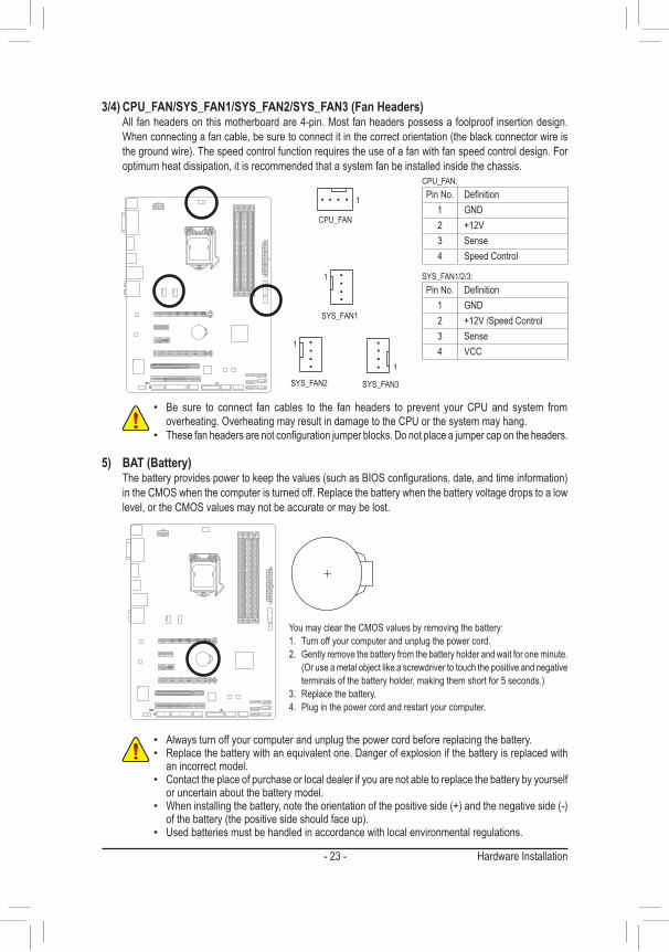
3/4) CPU_FAN/SYS_FAN1/SYS_FAN2/SYS_FAN3 (Fan Headers) All fan headers on this motherboard are 4-pin. Most fan headers possess a foolproof insertion design.
Whenconnectingafancable,besuretoconnectitinthecorrectorientation(theblackconnectorwireisthegroundwire).Thespeedcontrolfunctionrequirestheuseofafanwithfanspeedcontroldesign.Foroptimum heat dissipation, it is recommended that a system fan be installed inside the chassis.
CPU_FAN:PinNo. Definition
1 GND2 +12V3 Sense4 Speed Control
SYS_FAN1/2/3:PinNo. Definition
1 GND2 +12V /Speed Control3 Sense4 VCC
CPU_FAN
SYS_FAN1
DEBUG PORT
1
SYS_FAN3
DEBUG PORT
1
DEBUG PORT
1
5) BAT (Battery) Thebatteryprovidespowertokeepthevalues(suchasBIOSconfigurations,date,andtimeinformation)
in the CMOS when the computer is turned off. Replace the battery when the battery voltage drops to a low level, or the CMOS values may not be accurate or may be lost.
You may clear the CMOS values by removing the battery:1. Turn off your computer and unplug the power cord.2. Gently remove the battery from the battery holder and wait for one minute.
(Oruseametalobjectlikeascrewdrivertotouchthepositiveandnegativeterminalsofthebatteryholder,makingthemshortfor5seconds.)
3. Replace the battery.4. Plug in the power cord and restart your computer.
• Always turn off your computer and unplug the power cord before replacing the battery. • Replace the battery with an equivalent one. Danger of explosion if the battery is replaced with
an incorrect model. • Contact the place of purchase or local dealer if you are not able to replace the battery by yourself
or uncertain about the battery model. • Wheninstallingthebattery,notetheorientationofthepositiveside(+)andthenegativeside(-)ofthebattery(thepositivesideshouldfaceup).
• Used batteries must be handled in accordance with local environmental regulations.
SYS_FAN2
DEBUG PORT
1
- 24 -Hardware Installation
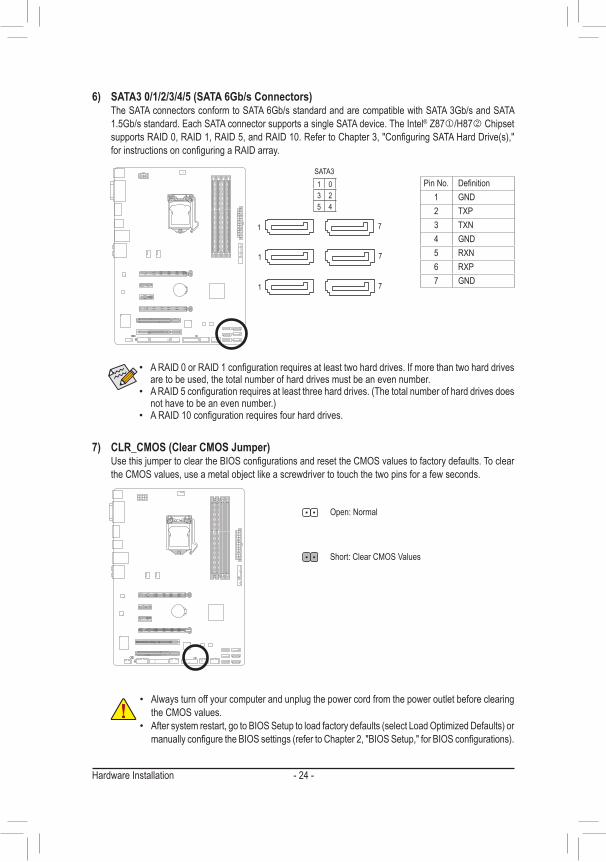
6) SATA3 0/1/2/3/4/5 (SATA 6Gb/s Connectors) The SATA connectors conform to SATA 6Gb/s standard and are compatible with SATA 3Gb/s and SATA
1.5Gb/s standard. Each SATA connector supports a single SATA device. The Intel® Z87j/H87k Chipset supportsRAID0,RAID1,RAID5,andRAID10.RefertoChapter3,"ConfiguringSATAHardDrive(s),"forinstructionsonconfiguringaRAIDarray.
• ARAID0orRAID1configurationrequiresatleasttwoharddrives.Ifmorethantwoharddrivesare to be used, the total number of hard drives must be an even number.
• ARAID5configurationrequiresatleastthreeharddrives.(Thetotalnumberofharddrivesdoesnothavetobeanevennumber.)
• ARAID10configurationrequiresfourharddrives.
SATA3PinNo. Definition
1 GND2 TXP3 TXN4 GND5 RXN6 RXP7 GND
1 03 25 4
7
DEBUG PORT
DEBUG PORT
7
DEBUG PORT
7
1
DEBUG PORT
DEBUG PORT
1
1
DEBUG PORT
7) CLR_CMOS (Clear CMOS Jumper) UsethisjumpertocleartheBIOSconfigurationsandresettheCMOSvaluestofactorydefaults.Toclear
the CMOS values, use a metal object like a screwdriver to touch the two pins for a few seconds.
• Always turn off your computer and unplug the power cord from the power outlet before clearing the CMOS values.
• Aftersystemrestart,gotoBIOSSetuptoloadfactorydefaults(selectLoadOptimizedDefaults)ormanuallyconfiguretheBIOSsettings(refertoChapter2,"BIOSSetup,"forBIOSconfigurations).
Open:Normal
Short: Clear CMOS Values
- 25 - Hardware Installation
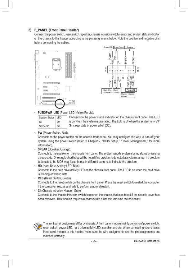
The front panel design may differ by chassis. A front panel module mainly consists of power switch, resetswitch,powerLED,harddriveactivityLED,speakerandetc.Whenconnectingyourchassisfront panel module to this header, make sure the wire assignments and the pin assignments are matched correctly.
8) F_PANEL (Front Panel Header) Connect the power switch, reset switch, speaker, chassis intrusion switch/sensor and system status indicator
onthechassistothisheaderaccordingtothepinassignmentsbelow.Notethepositiveandnegativepinsbefore connecting the cables.
• PW(PowerSwitch,Red): Connectstothepowerswitchonthechassisfrontpanel.Youmayconfigurethewaytoturnoffyour
systemusing thepower switch (refer toChapter2, "BIOSSetup," "PowerManagement," formoreinformation).
• SPEAK(Speaker,Orange): Connects to the speaker on the chassis front panel. The system reports system startup status by issuing
a beep code. One single short beep will be heard if no problem is detected at system startup. If a problem is detected, the BIOS may issue beeps in different patterns to indicate the problem.
• HD(HardDriveActivityLED,Blue): Connects to the hard drive activity LED on the chassis front panel. The LED is on when the hard drive
is reading or writing data.• RES(ResetSwitch,Green): Connects to the reset switch on the chassis front panel. Press the reset switch to restart the computer
ifthecomputerfreezesandfailstoperformanormalrestart.• CI(ChassisIntrusionHeader,Gray): Connects to the chassis intrusion switch/sensor on the chassis that can detect if the chassis cover has
been removed. This function requires a chassis with a chassis intrusion switch/sensor.
Power LED
DEBUG PORT
12
1920
CI- CI
+
PWR_
LED-
PWR_
LED+
PLED
-
PW-
SPEA
K+
SPEA
K-PLED
+
PW+
Power LED
HD-
RES+
HD+
RES-
Hard Drive Activity LED
Reset Switch Chassis Intrusion
Header
Power Switch Speaker
PWR_
LED-
• PLED/PWR_LED (PowerLED,Yellow/Purple):Connects to the power status indicator on the chassis front panel. The LED is on when the system is operating. The LED is off when the system is in S3/S4sleepstateorpoweredoff(S5).
System Status LEDS0 OnS3/S4/S5 Off
- 26 -Hardware Installation
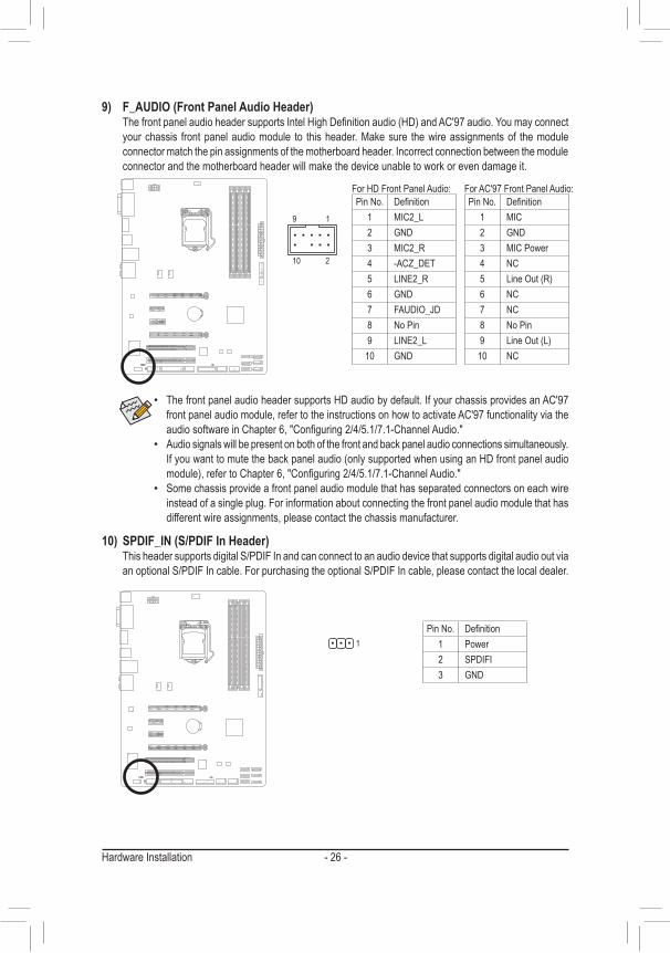
9) F_AUDIO (Front Panel Audio Header) ThefrontpanelaudioheadersupportsIntelHighDefinitionaudio(HD)andAC'97audio.Youmayconnect
your chassis front panel audio module to this header. Make sure the wire assignments of the module connector match the pin assignments of the motherboard header. Incorrect connection between the module connector and the motherboard header will make the device unable to work or even damage it.
• The front panel audio header supports HD audio by default. If your chassis provides an AC'97 front panel audio module, refer to the instructions on how to activate AC'97 functionality via the audiosoftwareinChapter6,"Configuring2/4/5.1/7.1-ChannelAudio."
• Audio signals will be present on both of the front and back panel audio connections simultaneously. Ifyouwanttomutethebackpanelaudio(onlysupportedwhenusinganHDfrontpanelaudiomodule),refertoChapter6,"Configuring2/4/5.1/7.1-ChannelAudio."
• Some chassis provide a front panel audio module that has separated connectors on each wire instead of a single plug. For information about connecting the front panel audio module that has different wire assignments, please contact the chassis manufacturer.
For HD Front Panel Audio: For AC'97 Front Panel Audio:PinNo. Definition
1 MIC2_L2 GND3 MIC2_R4 -ACZ_DET5 LINE2_R6 GND7 FAUDIO_JD8 NoPin9 LINE2_L
10 GND
PinNo. Definition1 MIC2 GND3 MIC Power4 NC5 LineOut(R)6 NC7 NC8 NoPin9 LineOut(L)
10 NC
F_USB30 F_AUDIO(H)
DB_PORT
F_PANEL(NH) F_PANEL(H61M-D2)
TPMw/housing
9 1
10 2
1
10) SPDIF_IN (S/PDIF In Header) This header supports digital S/PDIF In and can connect to an audio device that supports digital audio out via
an optional S/PDIF In cable. For purchasing the optional S/PDIF In cable, please contact the local dealer.
PinNo. Definition1 Power2 SPDIFI3 GND
- 27 - Hardware Installation
1
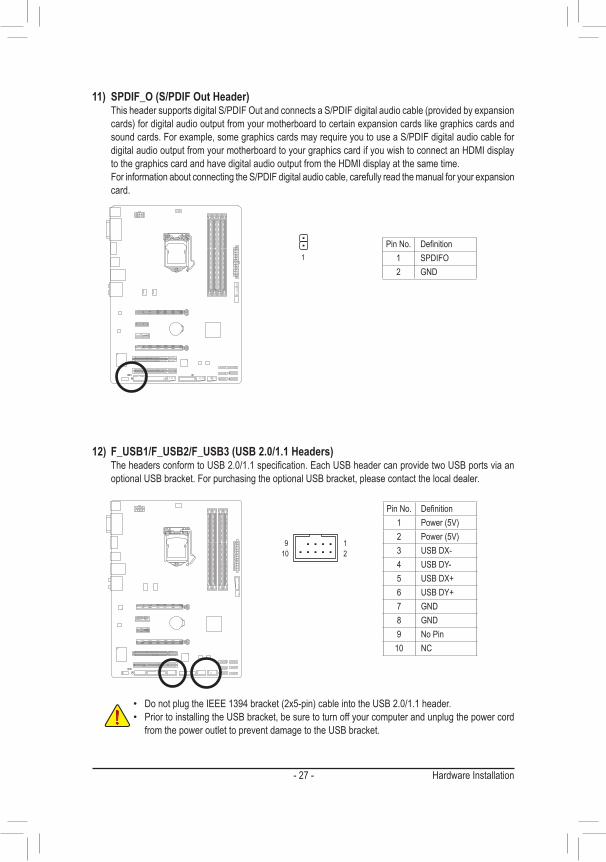
11) SPDIF_O (S/PDIF Out Header) ThisheadersupportsdigitalS/PDIFOutandconnectsaS/PDIFdigitalaudiocable(providedbyexpansion
cards)fordigitalaudiooutputfromyourmotherboardtocertainexpansioncardslikegraphicscardsandsound cards. For example, some graphics cards may require you to use a S/PDIF digital audio cable for digital audio output from your motherboard to your graphics card if you wish to connect an HDMI display to the graphics card and have digital audio output from the HDMI display at the same time.
For information about connecting the S/PDIF digital audio cable, carefully read the manual for your expansion card.
PinNo. Definition1 SPDIFO2 GND
12) F_USB1/F_USB2/F_USB3 (USB 2.0/1.1 Headers) TheheadersconformtoUSB2.0/1.1specification.EachUSBheadercanprovidetwoUSBportsviaan
optional USB bracket. For purchasing the optional USB bracket, please contact the local dealer.DEBUG PORT
109
21
PinNo. Definition1 Power(5V)2 Power(5V)3 USBDX-4 USB DY-5 USBDX+6 USB DY+7 GND8 GND9 NoPin
10 NC
• DonotplugtheIEEE1394bracket(2x5-pin)cableintotheUSB2.0/1.1header. • Prior to installing the USB bracket, be sure to turn off your computer and unplug the power cord
from the power outlet to prevent damage to the USB bracket.
- 28 -Hardware Installation
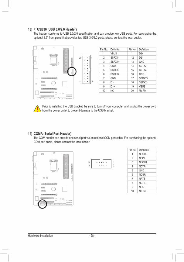
13) F_USB30 (USB 3.0/2.0 Header) TheheaderconformstoUSB3.0/2.0specificationandcanprovidetwoUSBports.Forpurchasingthe
optional 3.5" front panel that provides two USB 3.0/2.0 ports, please contact the local dealer.
PinNo. Definition PinNo. Definition1 VBUS 11 D2+2 SSRX1- 12 D2-3 SSRX1+ 13 GND4 GND 14 SSTX2+5 SSTX1- 15 SSTX2-6 SSTX1+ 16 GND7 GND 17 SSRX2+8 D1- 18 SSRX2-9 D1+ 19 VBUS
10 NC 20 NoPin
F_USB30F_AUDIO(H)
DB_PORT
F_PANEL(NH)F_PANEL(H61M-D2)
TPMw/housing
1011
20 1
109
21
14) COMA (Serial Port Header) The COM header can provide one serial port via an optional COM port cable. For purchasing the optional
COM port cable, please contact the local dealer.
PinNo. Definition1 NDCD-2 NSIN3 NSOUT4 NDTR-5 GND6 NDSR-7 NRTS-8 NCTS-9 NRI-
10 NoPin
Prior to installing the USB bracket, be sure to turn off your computer and unplug the power cord from the power outlet to prevent damage to the USB bracket.
- 29 - Hardware Installation
26
25
2
1
DEBUG PORT
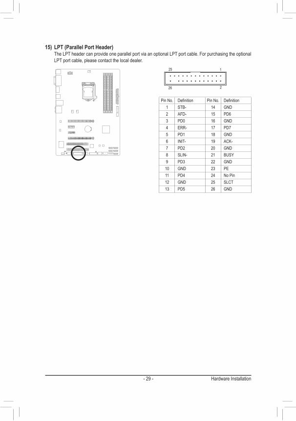
15) LPT (Parallel Port Header) The LPT header can provide one parallel port via an optional LPT port cable. For purchasing the optional
LPT port cable, please contact the local dealer.
PinNo. Definition PinNo. Definition1 STB- 14 GND2 AFD- 15 PD63 PD0 16 GND4 ERR- 17 PD75 PD1 18 GND6 INIT- 19 ACK-7 PD2 20 GND8 SLIN- 21 BUSY9 PD3 22 GND
10 GND 23 PE11 PD4 24 NoPin12 GND 25 SLCT13 PD5 26 GND

- 30 -Hardware Installation
- 31 - BIOS Setup
BIOS (Basic Input andOutputSystem) records hardware parameters of the system in theCMOSon themotherboard.Itsmajorfunctions includeconductingthePower-OnSelf-Test(POST)duringsystemstartup,saving system parameters and loading operating system, etc. BIOS includes a BIOS Setup program that allows theusertomodifybasicsystemconfigurationsettingsortoactivatecertainsystemfeatures.
Whenthepoweristurnedoff,thebatteryonthemotherboardsuppliesthenecessarypowertotheCMOStokeeptheconfigurationvaluesintheCMOS.
ToaccesstheBIOSSetupprogram,pressthe<Delete>keyduringthePOSTwhenthepoweristurnedon.
To upgrade the BIOS, use either the GIGABYTE Q-Flash or @BIOS utility. • Q-Flash allows the user to quickly and easily upgrade or back up BIOS without entering the operating system. • @BIOSisaWindows-basedutilitythatsearchesanddownloadsthelatestversionofBIOSfromtheInternet
and updates the BIOS.For instructions on using the Q-Flash and @BIOS utilities, refer to Chapter 5, "BIOS Update Utilities."
Chapter 2 BIOS Setup
• BecauseBIOSflashing ispotentially risky, ifyoudonotencounterproblemsusing thecurrentversionofBIOS, it is recommended thatyounotflash theBIOS.Toflash theBIOS,do itwithcaution.InadequateBIOSflashingmayresultinsystemmalfunction.
• Itisrecommendedthatyounotalterthedefaultsettings(unlessyouneedto)topreventsysteminstability or other unexpected results. Inadequately altering the settings may result in system's failure to boot. If this occurs, try to clear the CMOS values and reset the board to default values. (Refertothe"LoadOptimizedDefaults"sectioninthischapterorintroductionsofthebatteryortheclearCMOSjumperinChapter1forhowtocleartheCMOSvalues.)
BIOS Setup - 32 -
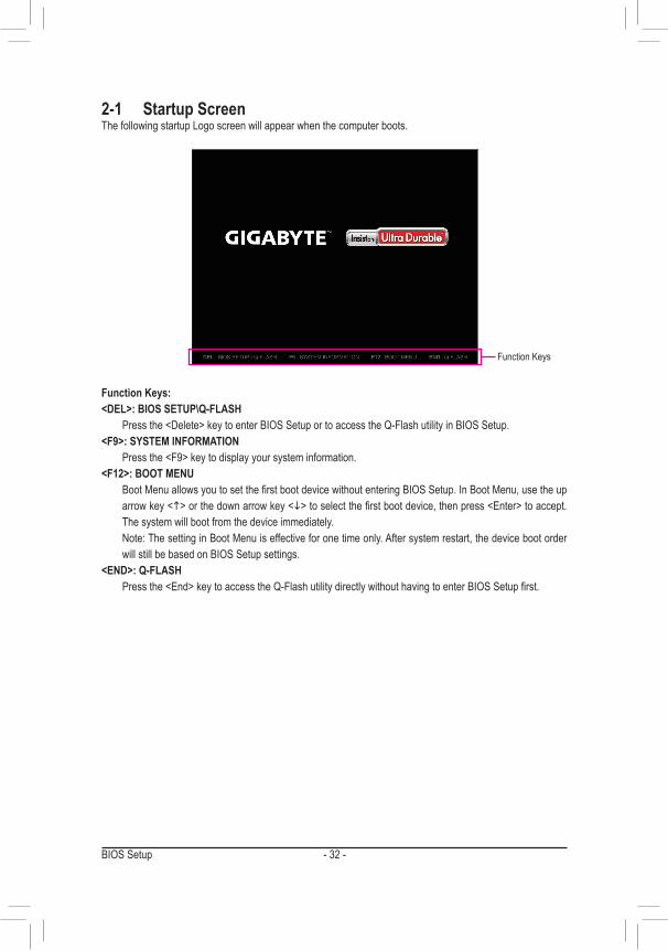
2-1 Startup ScreenThe following startup Logo screen will appear when the computer boots.
Function Keys:<DEL>: BIOS SETUP\Q-FLASH Pressthe<Delete>keytoenterBIOSSetuportoaccesstheQ-FlashutilityinBIOSSetup.<F9>: SYSTEM INFORMATION Pressthe<F9>keytodisplayyoursysteminformation.<F12>: BOOT MENU BootMenuallowsyoutosetthefirstbootdevicewithoutenteringBIOSSetup.InBootMenu,usetheup
arrow key <h>orthedownarrowkey<i>toselectthefirstbootdevice,thenpress<Enter>toaccept.The system will boot from the device immediately.
Note:ThesettinginBootMenuiseffectiveforonetimeonly.Aftersystemrestart,thedevicebootorderwill still be based on BIOS Setup settings.
<END>: Q-FLASH Pressthe<End>keytoaccesstheQ-FlashutilitydirectlywithouthavingtoenterBIOSSetupfirst.
Function Keys
- 33 - BIOS Setup
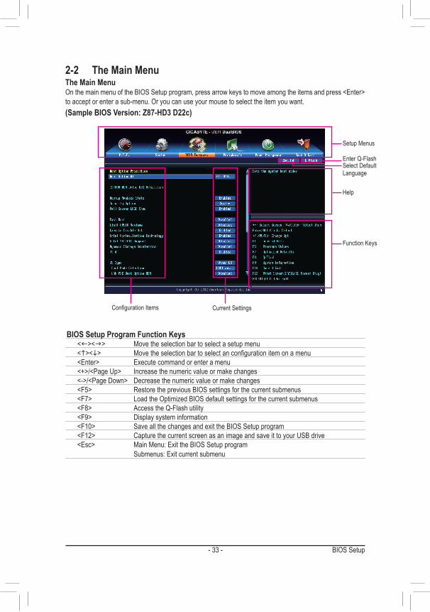
2-2 The Main MenuThe Main Menu OnthemainmenuoftheBIOSSetupprogram,pressarrowkeystomoveamongtheitemsandpress<Enter>to accept or enter a sub-menu. Or you can use your mouse to select the item you want.(Sample BIOS Version: Z87-HD3 D22c)
Setup Menus
Function Keys
Help
Enter Q-FlashSelect Default Language
ConfigurationItems Current Settings
BIOS Setup Program Function Keys<f><g> Move the selection bar to select a setup menu<h><i> Movetheselectionbartoselectanconfigurationitemonamenu<Enter> Execute command or enter a menu<+>/<PageUp> Increase the numeric value or make changes<->/<PageDown> Decrease the numeric value or make changes<F5> Restore the previous BIOS settings for the current submenus<F7> LoadtheOptimizedBIOSdefaultsettingsforthecurrentsubmenus<F8> Access the Q-Flash utility<F9> Display system information<F10> Save all the changes and exit the BIOS Setup program<F12> Capture the current screen as an image and save it to your USB drive<Esc> Main Menu: Exit the BIOS Setup program
Submenus: Exit current submenu
BIOS Setup - 34 -
BIOS Setup Menus � M.I.T.
Usethismenutoconfiguretheclock,frequency,andvoltagesofyourCPUandmemory,etc.Orcheckthesystem/CPU temperatures, voltages, and fan speeds.
� System UsethismenutoconfigurethedefaultlanguageusedbytheBIOSandsystemtimeanddate.Thismenu
also displays information on the devices connected to the SATA ports. � BIOS Features
Usethismenutoconfigurethedevicebootorder,advancedfeaturesavailableontheCPU,andtheprimarydisplay adapter.
� Peripherals Usethismenutoconfigureallperipheraldevices,suchasSATA,USB,integratedaudio,andintegrated
LAN,etc. � Power Management
Usethismenutoconfigureallthepower-savingfunctions. � Save & Exit
Save all the changes made in the BIOS Setup program to the CMOS and exit BIOS Setup. You can save thecurrentBIOSsettingstoaprofileorloadoptimizeddefaultsforoptimal-performancesystemoperations.
• Whenthesystemisnotstableasusual,select theLoad Optimized Defaults item to set your system to its defaults.
• The BIOS Setup menus described in this chapter are for reference only and may differ by BIOS version.
- 35 - BIOS Setup
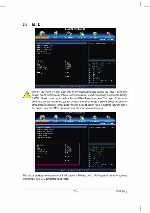
2-3 M.I.T.
Whetherthesystemwillworkstablywiththeoverclock/overvoltagesettingsyoumadeisdependentonyouroverallsystemconfigurations.Incorrectlydoingoverclock/overvoltagemayresultindamageto CPU, chipset, or memory and reduce the useful life of these components. This page is for advanced users only and we recommend you not to alter the default settings to prevent system instability or otherunexpectedresults.(Inadequatelyalteringthesettingsmayresultinsystem'sfailuretoboot.Ifthisoccurs,cleartheCMOSvaluesandresettheboardtodefaultvalues.)
This section provides information on the BIOS version, CPU base clock, CPU frequency, memory frequency, totalmemorysize,CPUtemperatureandVcore.
BIOS Setup - 36 -
` M.I.T. Current Status This screen provides information on CPU/memory frequencies/parameters.
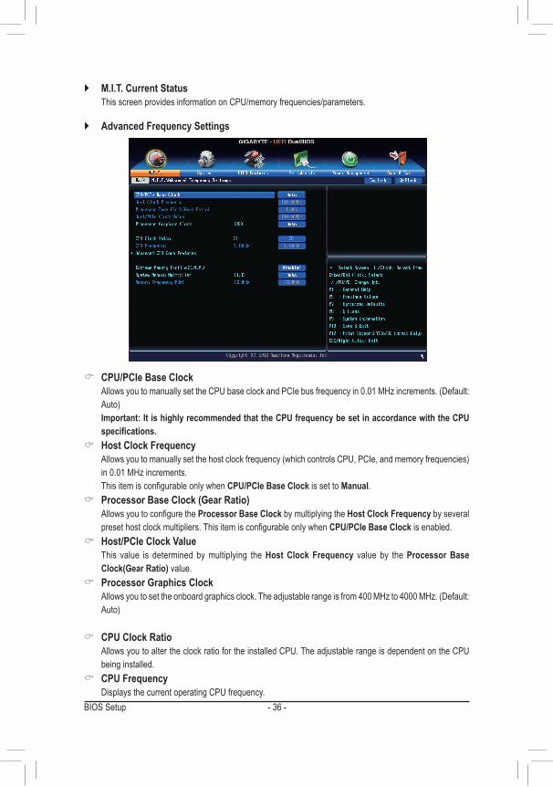
` Advanced Frequency Settings
& CPU/PCIe Base Clock AllowsyoutomanuallysettheCPUbaseclockandPCIebusfrequencyin0.01MHzincrements.(Default:
Auto) Important: It is highly recommended that the CPU frequency be set in accordance with the CPU
specifications. & Host Clock Frequency
Allowsyoutomanuallysetthehostclockfrequency(whichcontrolsCPU,PCIe,andmemoryfrequencies)in0.01MHzincrements.
ThisitemisconfigurableonlywhenCPU/PCIe Base Clock is set to Manual. & Processor Base Clock (Gear Ratio)
AllowsyoutoconfiguretheProcessor Base Clock by multiplying the Host Clock Frequency by several presethostclockmultipliers.ThisitemisconfigurableonlywhenCPU/PCIe Base Clock is enabled.
& Host/PCIe Clock Value This value is determined by multiplying the Host Clock Frequency value by the Processor Base
Clock(Gear Ratio) value. & Processor Graphics Clock
Allowsyoutosettheonboardgraphicsclock.Theadjustablerangeisfrom400MHzto4000MHz.(Default:Auto)
& CPU Clock Ratio Allows you to alter the clock ratio for the installed CPU. The adjustable range is dependent on the CPU
being installed. & CPU Frequency
Displays the current operating CPU frequency.
- 37 - BIOS Setup
(Note) ThisitemispresentonlywhenyouinstallaCPUthatsupportsthisfeature.FormoreinformationaboutIntel® CPUs' unique features, please visit Intel's website.
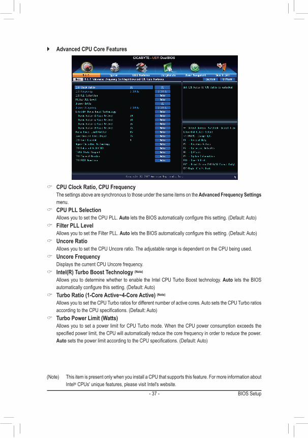
& CPU Clock Ratio, CPU Frequency The settings above are synchronous to those under the same items on the Advanced Frequency Settings
menu. & CPU PLL Selection
Allows you to set the CPU PLL. AutoletstheBIOSautomaticallyconfigurethissetting.(Default:Auto) & Filter PLL Level
Allows you to set the Filter PLL. AutoletstheBIOSautomaticallyconfigurethissetting.(Default:Auto) & Uncore Ratio
Allows you to set the CPU Uncore ratio. The adjustable range is dependent on the CPU being used. & Uncore Frequency
Displays the current CPU Uncore frequency. & Intel(R) Turbo Boost Technology (Note)
Allows you to determine whether to enable the Intel CPU Turbo Boost technology. Auto lets the BIOS automaticallyconfigurethissetting.(Default:Auto)
& Turbo Ratio (1-Core Active~4-Core Active) (Note)
Allows you to set the CPU Turbo ratios for different number of active cores. Auto sets the CPU Turbo ratios accordingtotheCPUspecifications.(Default:Auto)
& Turbo Power Limit (Watts) Allowsyoutosetapower limit forCPUTurbomode.WhentheCPUpowerconsumptionexceedsthe
specifiedpowerlimit,theCPUwillautomaticallyreducethecorefrequencyinordertoreducethepower.AutosetsthepowerlimitaccordingtotheCPUspecifications.(Default:Auto)
` Advanced CPU Core Features
BIOS Setup - 38 -
& Core Current Limit (Amps) AllowsyoutosetacurrentlimitforCPUTurbomode.WhentheCPUcurrentexceedsthespecifiedcurrent
limit, the CPU will automatically reduce the core frequency in order to reduce the current. Auto sets the powerlimitaccordingtotheCPUspecifications.(Default:Auto)
& CPU Core Enabled (Note 1)
Allows you to determine whether to enable all CPU cores. AutoletstheBIOSautomaticallyconfigurethissetting.(Default:Auto)
& Hyper-Threading Technology (Note 1)
Allows you to determine whether to enable multi-threading technology when using an Intel® CPU that supports this function. This feature only works for operating systems that support multi-processor mode. AutoletstheBIOSautomaticallyconfigurethissetting.(Default:Auto)
& CPU Enhanced Halt (C1E) (Note 1) Enables or disables Intel®CPUEnhancedHalt(C1E)function,aCPUpower-savingfunctioninsystem
haltstate.Whenenabled,theCPUcorefrequencyandvoltagewillbereducedduringsystemhaltstatetodecrease power consumption. AutoletstheBIOSautomaticallyconfigurethissetting.(Default:Auto)
& C3/C6 State Support (Note 1)
AllowsyoutodeterminewhethertolettheCPUenterC3/C6modeinsystemhaltstate.Whenenabled,theCPU core frequency and voltage will be reduced during system halt state to decrease power consumption. The C3/C6 state is a more enhanced power-saving state than C1. AutoletstheBIOSautomaticallyconfigurethissetting.(Default:Auto)
& CPU Thermal Monitor (Note 1)
Enables or disables Intel®ThermalMonitorfunction,aCPUoverheatingprotectionfunction.Whenenabled,the CPU core frequency and voltage will be reduced when the CPU is overheated. Auto lets the BIOS automaticallyconfigurethissetting.(Default:Auto)
& CPU EIST Function (Note 1)
Enables or disables Enhanced Intel®SpeedStepTechnology(EIST).DependingonCPUloading,IntelEIST technology can dynamically and effectively lower the CPU voltage and core frequency to decrease average power consumption and heat production. AutoletstheBIOSautomaticallyconfigurethissetting.(Default:Auto)
& ExtremeMemoryProfile(X.M.P.)(Note 2)
AllowstheBIOStoreadtheSPDdataonXMPmemorymodule(s)toenhancememoryperformancewhenenabled.
�Disabled Disablesthisfunction.(Default) �Profile1 UsesProfile1settings. �Profile2(Note2) UsesProfile2settings.
& System Memory Multiplier Allows you to set the system memory multiplier. Auto sets memory multiplier according to memory SPD
data.(Default:Auto) & Memory Frequency (MHz)
Thefirstmemoryfrequencyvalueisthenormaloperatingfrequencyofthememorybeingused;thesecondis the memory frequency that is automatically adjusted according to the System Memory Multiplier settings.
(Note1) ThisitemispresentonlywhenyouinstallaCPUthatsupportsthisfeature.FormoreinformationaboutIntel® CPUs' unique features, please visit Intel's website.
(Note2) ThisitemispresentonlywhenyouinstallaCPUandamemorymodulethatsupportthisfeature.
- 39 - BIOS Setup
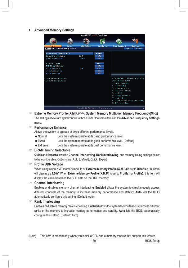
` Advanced Memory Settings
& ExtremeMemoryProfile(X.M.P.)(Note), System Memory Multiplier, Memory Frequency(MHz) The settings above are synchronous to those under the same items on the Advanced Frequency Settings
menu. & Performance Enhance
Allows the system to operate at three different performance levels. �Normal Letsthesystemoperateatitsbasicperformancelevel. �Turbo Letsthesystemoperateatitsgoodperformancelevel.(Default) �Extreme Lets the system operate at its best performance level.
& DRAM Timing Selectable Quick and Expert allows the Channel Interleaving, Rank Interleaving, and memory timing settings below
tobeconfigurable.Optionsare:Auto(default),Quick,Expert. & ProfileDDRVoltage
Whenusinganon-XMPmemorymoduleorExtremeMemoryProfile(X.M.P.) is set to Disabled, this item will display as 1.50V.WhenExtremeMemoryProfile(X.M.P.) is set to Profile1 or Profile2, this item will displaythevaluebasedontheSPDdataontheXMPmemory.
& Channel Interleaving Enables or disables memory channel interleaving. Enabled allows the system to simultaneously access
different channels of the memory to increase memory performance and stability. Auto lets the BIOS automaticallyconfigurethissetting.(Default:Auto)
& Rank Interleaving Enables or disables memory rank interleaving. Enabled allows the system to simultaneously access different
ranks of the memory to increase memory performance and stability. Auto lets the BIOS automatically configurethissetting.(Default:Auto)
(Note) ThisitemispresentonlywhenyouinstallaCPUandamemorymodulethatsupportthisfeature.
BIOS Setup - 40 -
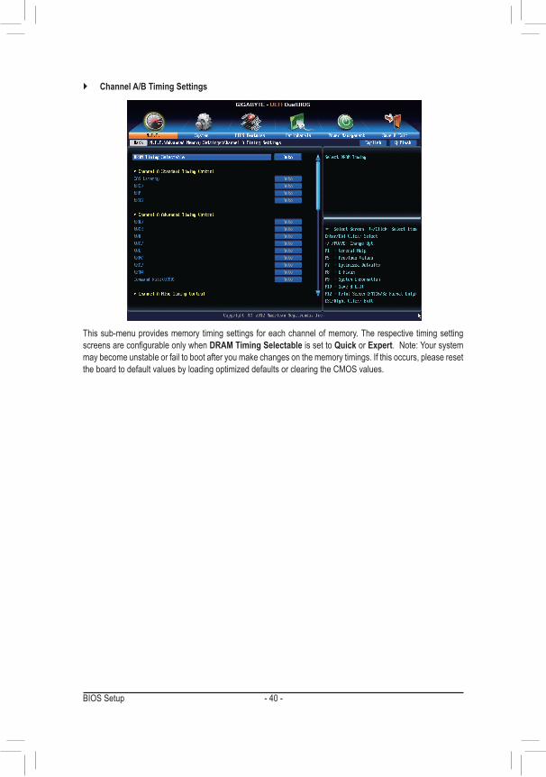
This sub-menu provides memory timing settings for each channel of memory. The respective timing setting screensareconfigurableonlywhenDRAM Timing Selectable is set to Quick or Expert.Note:Yoursystemmay become unstable or fail to boot after you make changes on the memory timings. If this occurs, please reset theboardtodefaultvaluesbyloadingoptimizeddefaultsorclearingtheCMOSvalues.
` Channel A/B Timing Settings
- 41 - BIOS Setup
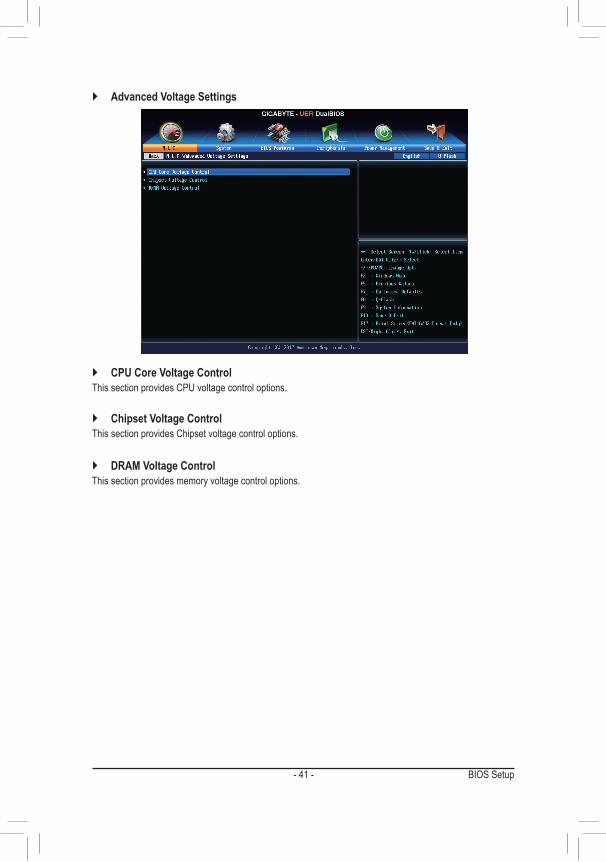
` CPU Core Voltage ControlThis section provides CPU voltage control options.
` Chipset Voltage ControlThis section provides Chipset voltage control options.
` DRAM Voltage ControlThis section provides memory voltage control options.
` Advanced Voltage Settings
BIOS Setup - 42 -
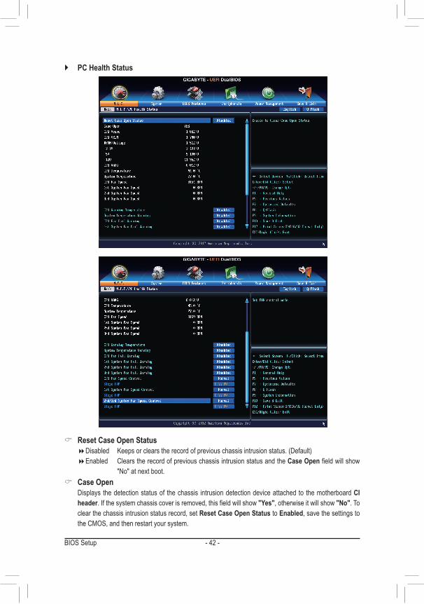
` PC Health Status
& Reset Case Open Status �Disabled Keepsorclearstherecordofpreviouschassisintrusionstatus.(Default) �Enabled Clears the record of previous chassis intrusion status and the Case Openfieldwillshow
"No"atnextboot. & Case Open
Displays the detection status of the chassis intrusion detection device attached to the motherboard CI header.Ifthesystemchassiscoverisremoved,thisfieldwillshow"Yes", otherwise it will show "No". To clear the chassis intrusion status record, set Reset Case Open Status to Enabled, save the settings to the CMOS, and then restart your system.
- 43 - BIOS Setup
& CPU Vcore/CPU VRIN/DRAM Voltage/+3.3V/+5V/+12V/CPU VAXG Displays the current system voltages.
& CPU/System Temperature Displays current CPU/System temperature.
& CPU/System Fan Speed Displays current CPU/system fan speeds.
& CPU/System Warning Temperature SetsthewarningthresholdforCPU/systemtemperature.WhenCPUtemperatureexceedsthethreshold,
BIOSwill emitwarning sound.Options are:Disabled (default), 60oC/140oF, 70oC/158oF, 80oC/176oF, 90oC/194oF.
& CPU/System Fan Fail Warning Allows the system to emit warning sound if the fan is not connected or fail. Check the fan condition or fan
connectionwhenthisoccurs.(Default:Disabled) & CPU Fan Speed Control (CPU_FAN Connector)
Allows you to determine whether to enable the fan speed control function for the fan connected to the CPU_FANconnectorandadjustthefanspeed.
�Normal AllowsthefantorunatdifferentspeedsaccordingtotheCPUtemperature.YoucanadjustthefanspeedwithEasyTunebasedonyoursystemrequirements.(Default)
�Silent Allows the fan to run at slow speeds. �Manual Allows you to control the fan speed under the Slope PWM item. �Disabled Allows the fan to run at full speeds.
& Slope PWM Allowsyoutocontrolthefanspeed.ThisitemisconfigurableonlywhenCPU Fan Speed Control is set
to Manual.Optionsare:0.75PWMvalue/oC~2.50PWMvalue/oC. & 1st System Fan Speed Control (SYS_FAN1 Connector)
Allows you to determine whether to enable the fan speed control function for the fan connected to the SYS_FAN1connectorandadjustthefanspeed.
�Normal Allowsthefantorunatdifferentspeedsaccordingtothesystemtemperature.YoucanadjustthefanspeedwithEasyTunebasedonyoursystemrequirements.(Default)
�Silent Allows the fan to run at slow speeds. �Manual Allows you to control the fan speed under the Slope PWM item. �Disabled Allows the fan to run at full speeds.
& Slope PWM Allowsyoutocontrolthefanspeed.Thisitemisconfigurableonlywhen1st System Fan Speed Control
is set to Manual.Optionsare:0.75PWMvalue/oC~2.50PWMvalue/oC. & 2nd/3rd System Fan Speed Control
Allows you to determine whether to enable the fan speed control function for the system fan connected to theSYS_FAN2/3connectorandadjustthefanspeed.
�Normal Allowsthefantorunatdifferentspeedsaccordingtothesystemtemperature.(Default) �Silent Allows the fan to run at slow speeds. �Manual AllowsyoutocontrolthefanspeedundertheSlopePWMitem. �Disabled Allows the fan to run at full speeds.
BIOS Setup - 44 -
& Slope PWM Allowsyoutocontrol thefanspeed.This itemisconfigurableonlywhen2nd/3rd System Fan Speed
Control is set to Manual.Optionsare:0.75PWMvalue/oC~2.50PWMvalue/oC.
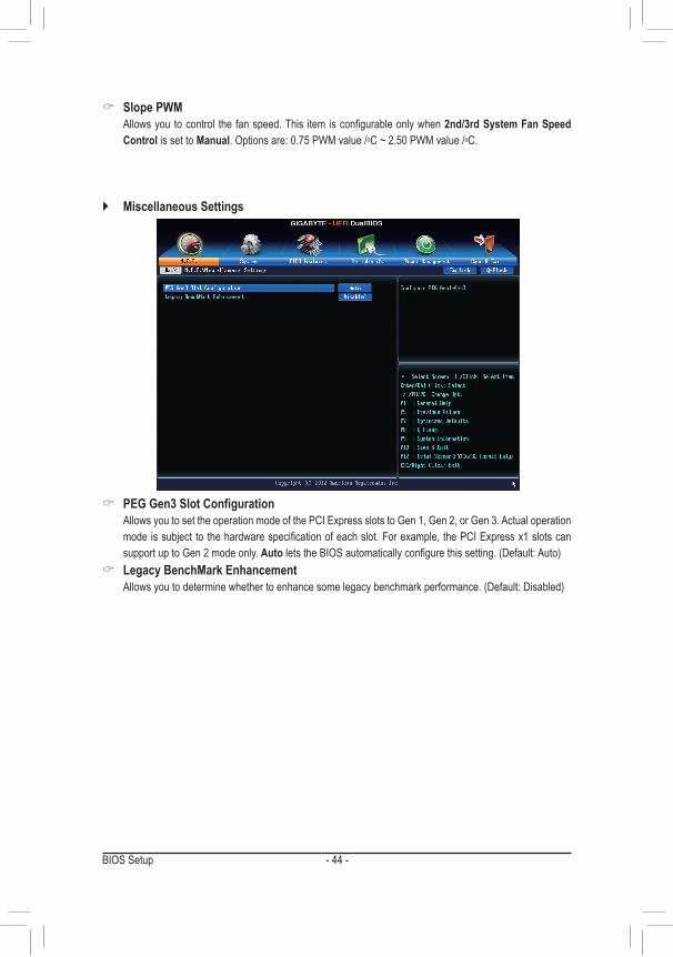
` Miscellaneous Settings
& PEGGen3SlotConfiguration Allows you to set the operation mode of the PCI Express slots to Gen 1, Gen 2, or Gen 3. Actual operation
modeissubjecttothehardwarespecificationofeachslot.Forexample,thePCIExpressx1slotscansupport up to Gen 2 mode only. AutoletstheBIOSautomaticallyconfigurethissetting.(Default:Auto)
& Legacy BenchMark Enhancement Allowsyoutodeterminewhethertoenhancesomelegacybenchmarkperformance.(Default:Disabled)
- 45 - BIOS Setup
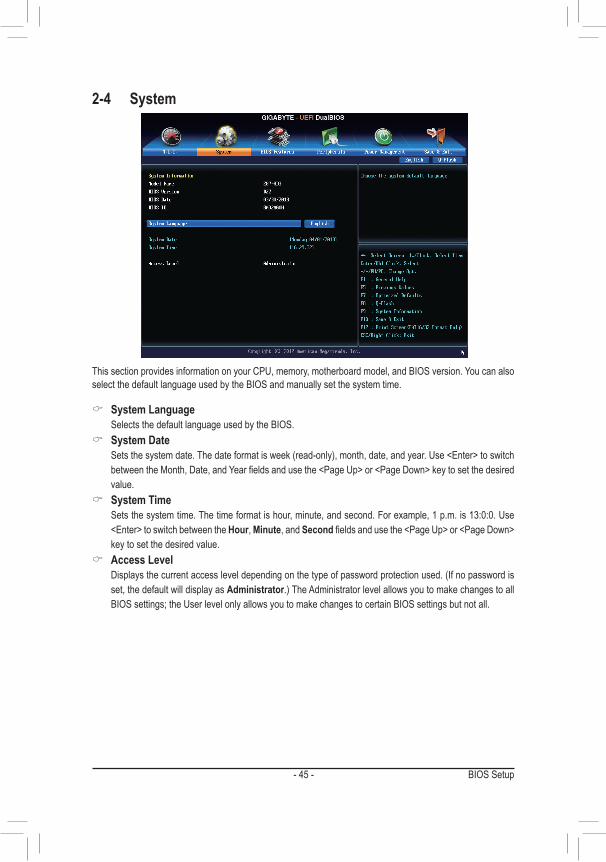
2-4 System
This section provides information on your CPU, memory, motherboard model, and BIOS version. You can also select the default language used by the BIOS and manually set the system time.
& System Language Selects the default language used by the BIOS.
& System Date Setsthesystemdate.Thedateformatisweek(read-only),month,date,andyear.Use<Enter>toswitch
betweentheMonth,Date,andYearfieldsandusethe<PageUp>or<PageDown>keytosetthedesiredvalue.
& System Time Sets the system time. The time format is hour, minute, and second. For example, 1 p.m. is 13:0:0. Use
<Enter>toswitchbetweentheHour, Minute, and Secondfieldsandusethe<PageUp>or<PageDown>key to set the desired value.
& Access Level Displaysthecurrentaccessleveldependingonthetypeofpasswordprotectionused.(Ifnopasswordis
set, the default will display as Administrator.)TheAdministratorlevelallowsyoutomakechangestoallBIOSsettings;theUserlevelonlyallowsyoutomakechangestocertainBIOSsettingsbutnotall.
BIOS Setup - 46 -
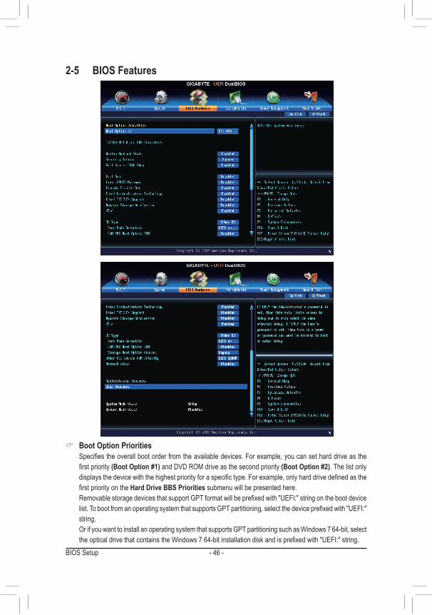
2-5 BIOS Features
& Boot Option Priorities Specifiestheoverallbootorderfromtheavailabledevices.Forexample,youcansetharddriveasthe
firstpriority(Boot Option #1) and DVD ROM drive as the second priority (Boot Option #2). The list only displaysthedevicewiththehighestpriorityforaspecifictype.Forexample,onlyharddrivedefinedasthefirstpriorityontheHard Drive BBS Priorities submenu will be presented here.
RemovablestoragedevicesthatsupportGPTformatwillbeprefixedwith"UEFI:"stringonthebootdevicelist.TobootfromanoperatingsystemthatsupportsGPTpartitioning,selectthedeviceprefixedwith"UEFI:"string.
OrifyouwanttoinstallanoperatingsystemthatsupportsGPTpartitioningsuchasWindows764-bit,selecttheopticaldrivethatcontainstheWindows764-bitinstallationdiskandisprefixedwith"UEFI:"string.
- 47 - BIOS Setup
& Hard Drive/CD/DVD ROM Drive/Floppy Drive/Network Device BBS Priorities Specifiesthebootorderforaspecificdevicetype,suchasharddrives,opticaldrives,floppydiskdrives,
anddevicesthatsupportBootfromLANfunction,etc.Press<Enter>onthisitemtoenterthesubmenuthatpresents the devices of the same type that are connected. This item is present only if at least one device for this type is installed.
& Bootup NumLock State EnablesordisablesNumlockfeatureonthenumerickeypadofthekeyboardafterthePOST.(Default:
Enabled) & Security Option
Specifieswhetherapasswordisrequiredeverytimethesystemboots,oronlywhenyouenterBIOSSetup.Afterconfiguringthisitem,setthepassword(s)underthe Administrator Password/User Password item.
�Setup A password is only required for entering the BIOS Setup program. �System A password is required for booting the system and for entering the BIOS Setup program.
(Default) & Full Screen LOGO Show
Allows you to determine whether to display the GIGABYTE Logo at system startup. Disabled skips the GIGABYTELogowhenthesystemstartsup.(Default:Enabled)
& Fast Boot Enables or disables Fast Boot to shorten the OS boot process. Ultra Fast provides the fastest bootup
speed.(Default:Disabled) & Limit CPUID Maximum (Note)
Allows you to determine whether to limit CPUID maximum value. Set this item to DisabledforWindowsXPoperatingsystem;setthisitemtoEnabledforlegacyoperatingsystemsuchasWindowsNT4.0.(Default:Disabled)
& Execute Disable Bit (Note)
Enables or disables Intel® Execute Disable Bit function. This function may enhance protection for the computer, reducing exposure to viruses andmalicious buffer overflowattackswhenworkingwith itssupportingsoftwareandsystem.(Default:Enabled)
& Intel Virtualization Technology (Note)
Enables or disables Intel® VirtualizationTechnology. Virtualization enhanced by Intel® VirtualizationTechnology will allow a platform to run multiple operating systems and applications in independent partitions. Withvirtualization,onecomputersystemcanfunctionasmultiplevirtualsystems.(Default:Enabled)
& Intel TXT(LT) Support (Note)
Enables or disables Intel® Trusted Execution Technology(Intel®TXT).Intel® Trusted Execution Technology providesahardware-basedsecurityfoundation.(Default:Disabled)
& Dynamic Storage Accelerator j Enables or disables Intel®DynamicStorageAccelerator.Whenenabled,theharddriveI/Operformance
willbeadjustedaccordingtoharddriveload.(Default:Disabled) & VT-d (Note)
Enables or disablesIntel®VirtualizationTechnologyforDirectedI/O.(Default:Enabled)
(Note) ThisitemispresentonlywhenyouinstallaCPUthatsupportsthisfeature.FormoreinformationaboutIntel® CPUs' unique features, please visit Intel's website.
j Only for GA-Z87-HD3.
BIOS Setup - 48 -
& OS Type Allowsyoutoselecttheoperatingsystemtobeinstalled.(Default:OtherOS)
& CSM Support EnablesordisablesUEFICSM(CompatibilitySupportModule)tosupportalegacyPCbootprocess.
�Always EnablesUEFICSM.(Default) �Never DisablesUEFICSMandsupportsUEFIBIOSbootprocessonly.
ThisitemisconfigurableonlywhenOS Type is set to Windows 8 or Windows 8 WHQL. & Boot Mode Selection
Allows you to select which type of operating system to boot. �UEFI and Legacy Allows booting from operating systems that support legacy option ROM or UEFI option
ROM.(Default) �Legacy only Allows booting from operating systems that only support legacy option ROM. �UEFI only Allows booting from operating systems that only support UEFI option ROM.
ThisitemisconfigurableonlywhenCSM Support is set to Always. & LAN PXE Boot Option ROM
AllowsyoutoselectwhethertoenablethelegacyoptionROMfortheLANcontroller.(Default:Disabled) ThisitemisconfigurableonlywhenCSM Support is set to Always.
& Storage Boot Option Control Allows you to select whether to enable the UEFI or legacy option ROM for the storage device controller.
�Disabled Disables option ROM. �Legacyonly EnableslegacyoptionROMonly.(Default) �UEFI only Enables UEFI option ROM only. �LegacyFirst EnableslegacyoptionROMfirst. �UEFIFirst EnablesUEFIoptionROMfirst.
Thisitemisconfigurableonlywhen CSM Support is set to Always. & Other PCI Device ROM Priority
Allows you to select whether to enable the UEFI or Legacy option ROM for the PCI device controller other thantheLAN,storagedevice,andgraphicscontrollers.
�Legacy OpROM Enables legacy option ROM only. �UEFIOpROM EnablesUEFIoptionROMonly.(Default)
& Network stack Disables or enables booting from the network to install a GPT format OS, such as installing the OS from
theWindowsDeploymentServicesserver.(Default:Disabled) & Ipv4 PXE Support
EnablesordisablesIPv4PXESupport.ThisitemisconfigurableonlywhenNetwork stack is enabled. & Ipv6 PXE Support
EnablesordisablesIPv6PXESupport.ThisitemisconfigurableonlywhenNetwork stack is enabled.
- 49 - BIOS Setup
& Administrator Password Allowsyoutoconfigureanadministratorpassword.Press<Enter>onthisitem,typethepassword,and
thenpress<Enter>.Youwillberequestedtoconfirmthepassword.Typethepasswordagainandpress<Enter>.Youmustentertheadministratorpassword(oruserpassword)atsystemstartupandwhenenteringBIOS Setup. Differing from the user password, the administrator password allows you to make changes to all BIOS settings.
& User Password Allowsyoutoconfigureauserpassword.Press<Enter>onthisitem,typethepassword,andthenpress
<Enter>.Youwillberequestedtoconfirmthepassword.Typethepasswordagainandpress<Enter>.Youmustentertheadministratorpassword(oruserpassword)atsystemstartupandwhenenteringBIOSSetup. However, the user password only allows you to make changes to certain BIOS settings but not all.
Tocancelthepassword,press<Enter>onthepassworditemandwhenrequestedforthepassword,enterthecorrectonefirst.Whenpromptedforanewpassword,press<Enter>withoutenteringanypassword.Press<Enter>againwhenpromptedtoconfirm.
BIOS Setup - 50 -
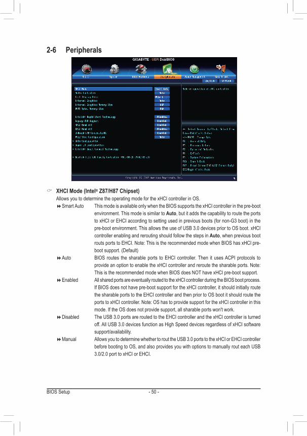
2-6 Peripherals
& XHCI Mode (Intel® Z87/H87 Chipset) Allows you to determine the operating mode for the xHCI controller in OS.
�Smart Auto This mode is available only when the BIOS supports the xHCI controller in the pre-boot environment. This mode is similar to Auto, but it adds the capability to route the ports toxHCIorEHCIaccordingtosettingusedinpreviousboots(fornon-G3boot)inthepre-boot environment. This allows the use of USB 3.0 devices prior to OS boot. xHCI controller enabling and rerouting should follow the steps in Auto, when previous boot routsportstoEHCI.Note:ThisistherecommendedmodewhenBIOShasxHCIpre-bootsupport.(Default)
�Auto BIOS routes the sharable ports to EHCI controller. Then it uses ACPI protocols to provideanoptiontoenablethexHCIcontrollerandreroutethesharableports.Note:ThisistherecommendedmodewhenBIOSdoesNOThavexHCIpre-bootsupport.
�Enabled All shared ports are eventually routed to the xHCI controller during the BIOS boot process. If BIOS does not have pre-boot support for the xHCI controller, it should initially route the sharable ports to the EHCI controller and then prior to OS boot it should route the portstoxHCIcontroller.Note:OShastoprovidesupportforthexHCIcontrollerinthismode. If the OS does not provide support, all sharable ports won't work.
�Disabled The USB 3.0 ports are routed to the EHCI controller and the xHCI controller is turned off. All USB 3.0 devices function as High Speed devices regardless of xHCI software support/availability.
�Manual Allows you to determine whether to rout the USB 3.0 ports to the xHCI or EHCI controller before booting to OS, and also provides you with options to manually rout each USB 3.0/2.0 port to xHCI or EHCI.
- 51 - BIOS Setup
& Audio Controller Enablesordisablestheonboardaudiofunction.(Default:Auto) If you wish to install a 3rd party add-in audio card instead of using the onboard audio, set this item to
Disabled. & Init Display First
SpecifiesthefirstinitiationofthemonitordisplayfromtheinstalledPCIgraphicscard,PCIExpressgraphicscard or the onboard graphics.
�IGFX Setstheonboardgraphicsasthefirstdisplay. �PCIe1Slot SetsthegraphicscardonthePCIEX16slotasthefirstdisplay.(Default) �PCIe2Slot SetsthegraphicscardonthePCIEX4slotasthefirstdisplay. �PCI SetsthegraphicscardonthePCIslotasthefirstdisplay.
& Internal Graphics Enablesordisablestheonboardgraphicsfunction.(Default:Auto)
& Internal Graphics Memory Size Allowsyoutosettheonboardgraphicsmemorysize.Optionsare:32M~1024M.(Default:64M)
& DVMT Total Memory Size AllowsyoutoallocatetheDVMTmemorysizeoftheonboardgraphics.Optionsare:128M,256M,MAX.
(Default:MAX)
& Intel(R) Rapid Start Technology Enables or disables Intel®RapidStartTechnology.(Default:Disabled)
& Legacy USB Support AllowsUSBkeyboard/mousetobeusedinMS-DOS.(Default:Enabled)
& XHCI Hand-off Determineswhether to enableXHCIHand-off feature for anoperating systemwithoutXHCIHand-off
support.(Default:Enabled) & EHCI Hand-off
Determines whether to enable EHCI Hand-off feature for an operating system without EHCI Hand-off support.(Default:Disabled)
& USB Storage Devices Displays a list of connected USB mass storage devices. This item appears only when a USB storage device
is installed. & OnBoard LAN Controller#1 (Realtek® GbE LAN Chip)
EnablesordisablestheonboardRealtekGbELANfunction.(Default:Enabled) Ifyouwishtoinstalla3rdpartyadd-innetworkcardinsteadofusingtheonboardLAN,setthisitemto
Disabled. & PCIESlotConfiguration
SpecifiestheoperatingbandwidthforthePCIEX4slot. �Auto LetstheBIOSautomaticallyconfigurethissettingdependingontheexpansioncardbeinginstalled.
(Default) �x1 PCIEX4operatesatx1mode. �x4 PCIEX4operatesatx4mode.
BIOS Setup - 52 -
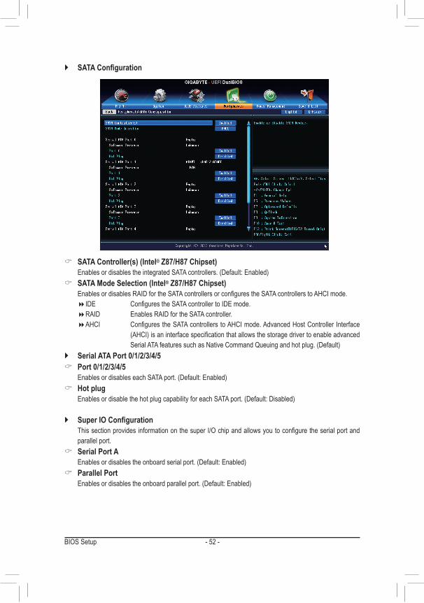
` SATAConfiguration
& SATA Controller(s) (Intel® Z87/H87 Chipset) EnablesordisablestheintegratedSATAcontrollers.(Default:Enabled)
& SATA Mode Selection (Intel® Z87/H87 Chipset) EnablesordisablesRAIDfortheSATAcontrollersorconfigurestheSATAcontrollerstoAHCImode.
�IDE ConfigurestheSATAcontrollertoIDEmode. �RAID Enables RAID for the SATA controller. �AHCI ConfigurestheSATAcontrollerstoAHCImode.AdvancedHostController Interface
(AHCI)isaninterfacespecificationthatallowsthestoragedrivertoenableadvancedSerialATAfeaturessuchasNativeCommandQueuingandhotplug.(Default)
` Serial ATA Port 0/1/2/3/4/5 & Port 0/1/2/3/4/5
EnablesordisableseachSATAport.(Default:Enabled) & Hot plug
EnablesordisablethehotplugcapabilityforeachSATAport.(Default:Disabled)
` SuperIOConfiguration ThissectionprovidesinformationonthesuperI/Ochipandallowsyoutoconfiguretheserialportand
parallel port. & Serial Port A
Enablesordisablestheonboardserialport.(Default:Enabled) & Parallel Port
Enablesordisablestheonboardparallelport.(Default:Enabled)
- 53 - BIOS Setup
& Device Mode ThisitemisconfigurableonlywhenParallel Port is set to Enabled. Selects an operating mode for the
onboardparallel(LPT)port.(Default),EPPMode(EnhancedParallelPort),ECPMode(ExtendedCapabilitiesPort),EPPMode&ECPMode.
` Intel(R) Smart Connect Technology & ISCTConfiguration
Enables or disables Intel®SmartConnectTechnology.(Default:Disabled)
` Realtek PCIe GBE Family Controller Thissub-menuprovidesinformationonLANconfiguration.
BIOS Setup - 54 -
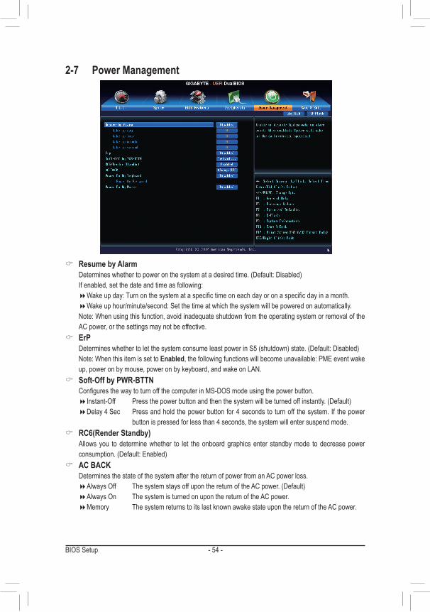
& Resume by Alarm Determineswhethertopoweronthesystematadesiredtime.(Default:Disabled) If enabled, set the date and time as following:
�Wakeupday:Turnonthesystemataspecifictimeoneachdayoronaspecificdayinamonth. �Wakeuphour/minute/second:Setthetimeatwhichthesystemwillbepoweredonautomatically.
Note:Whenusingthisfunction,avoidinadequateshutdownfromtheoperatingsystemorremovaloftheAC power, or the settings may not be effective.
& ErP DetermineswhethertoletthesystemconsumeleastpowerinS5(shutdown)state.(Default:Disabled) Note:WhenthisitemissettoEnabled, the following functions will become unavailable: PME event wake
up,poweronbymouse,poweronbykeyboard,andwakeonLAN. & Soft-Off by PWR-BTTN
ConfiguresthewaytoturnoffthecomputerinMS-DOSmodeusingthepowerbutton. �Instant-Off Pressthepowerbuttonandthenthesystemwillbeturnedoffinstantly.(Default) �Delay 4 Sec Press and hold the power button for 4 seconds to turn off the system. If the power
button is pressed for less than 4 seconds, the system will enter suspend mode. & RC6(Render Standby)
Allows you to determine whether to let the onboard graphics enter standby mode to decrease power consumption.(Default:Enabled)
& AC BACK Determines the state of the system after the return of power from an AC power loss.
�AlwaysOff ThesystemstaysoffuponthereturnoftheACpower.(Default) �Always On The system is turned on upon the return of the AC power. �Memory The system returns to its last known awake state upon the return of the AC power.
2-7 Power Management
- 55 - BIOS Setup
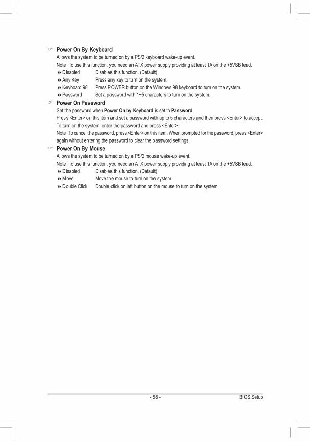
& Power On By Keyboard Allows the system to be turned on by a PS/2 keyboard wake-up event. Note:Tousethisfunction,youneedanATXpowersupplyprovidingatleast1Aonthe+5VSBlead.
�Disabled Disablesthisfunction.(Default) �Any Key Press any key to turn on the system. �Keyboard98 PressPOWERbuttonontheWindows98keyboardtoturnonthesystem. �Password Set a password with 1~5 characters to turn on the system.
& Power On Password Set the password when Power On by Keyboard is set to Password. Press<Enter>onthisitemandsetapasswordwithupto5charactersandthenpress<Enter>toaccept.
Toturnonthesystem,enterthepasswordandpress<Enter>. Note:Tocancelthepassword,press<Enter>onthisitem.Whenpromptedforthepassword,press<Enter>
again without entering the password to clear the password settings. & Power On By Mouse
Allows the system to be turned on by a PS/2 mouse wake-up event. Note:Tousethisfunction,youneedanATXpowersupplyprovidingatleast1Aonthe+5VSBlead.
�Disabled Disablesthisfunction.(Default) �Move Move the mouse to turn on the system. �Double Click Double click on left button on the mouse to turn on the system.
BIOS Setup - 56 -
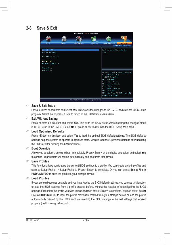
2-8 Save & Exit
& Save & Exit Setup Press<Enter>onthisitemandselectYes. This saves the changes to the CMOS and exits the BIOS Setup
program. Select Noorpress<Esc>toreturntotheBIOSSetupMainMenu. & Exit Without Saving
Press<Enter>onthisitemandselectYes. This exits the BIOS Setup without saving the changes made in BIOS Setup to the CMOS. Select Noorpress<Esc>toreturntotheBIOSSetupMainMenu.
& Load Optimized Defaults Press<Enter>onthisitemandselectYes to load the optimal BIOS default settings. The BIOS defaults
settingshelpthesystemtooperateinoptimumstate.AlwaysloadtheOptimizeddefaultsafterupdatingthe BIOS or after clearing the CMOS values.
& Boot Override Allowsyoutoselectadevicetobootimmediately.Press<Enter>onthedeviceyouselectandselectYes
toconfirm.Yoursystemwillrestartautomaticallyandbootfromthatdevice. & SaveProfiles
ThisfunctionallowsyoutosavethecurrentBIOSsettingstoaprofile.Youcancreateupto8profilesandsaveasSetupProfile1~SetupProfile8.Press<Enter>tocomplete.OryoucanselectSelect File in HDD/USB/FDDtosavetheprofiletoyourstoragedevice.
& LoadProfiles If your system becomes unstable and you have loaded the BIOS default settings, you can use this function
to load theBIOSsettings fromaprofilecreatedbefore,without thehasslesof reconfiguring theBIOSsettings.Firstselecttheprofileyouwishtoloadandthenpress<Enter>tocomplete.YoucanselectSelect File in HDD/USB/FDDtoinputtheprofilepreviouslycreatedfromyourstoragedeviceorloadtheprofileautomatically created by the BIOS, such as reverting the BIOS settings to the last settings that worked properly(lastknowngoodrecord).
- 57 - Configuring SATA Hard Drive(s)
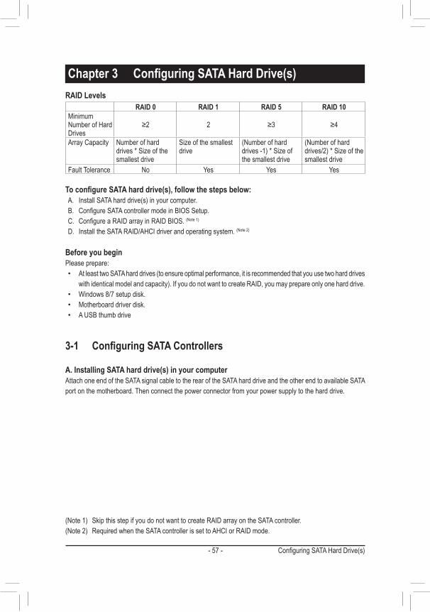
Chapter3 ConfiguringSATAHardDrive(s)
ToconfigureSATAharddrive(s),followthestepsbelow:A. InstallSATAharddrive(s)inyourcomputer.B. ConfigureSATAcontrollermodeinBIOSSetup.C. ConfigureaRAIDarrayinRAIDBIOS.(Note1)D. Install the SATA RAID/AHCI driver and operating system. (Note2)
Before you beginPlease prepare:
• AtleasttwoSATAharddrives(toensureoptimalperformance,itisrecommendedthatyouusetwoharddriveswithidenticalmodelandcapacity).IfyoudonotwanttocreateRAID,youmayprepareonlyoneharddrive.
• Windows8/7setupdisk. • Motherboard driver disk. • A USB thumb drive
RAID Levels
3-1 ConfiguringSATAControllers
A. Installing SATA hard drive(s) in your computerAttach one end of the SATA signal cable to the rear of the SATA hard drive and the other end to available SATA port on the motherboard. Then connect the power connector from your power supply to the hard drive.
RAID 0 RAID 1 RAID 5 RAID 10Minimum NumberofHardDrives
≥2 2 ≥3 ≥4
Array Capacity Numberofharddrives*Sizeofthesmallest drive
Sizeofthesmallestdrive
(Numberofharddrives-1)*Sizeofthe smallest drive
(Numberofharddrives/2)*Sizeofthesmallest drive
Fault Tolerance No Yes Yes Yes
(Note1) SkipthisstepifyoudonotwanttocreateRAIDarrayontheSATAcontroller.(Note2) RequiredwhentheSATAcontrollerissettoAHCIorRAIDmode.
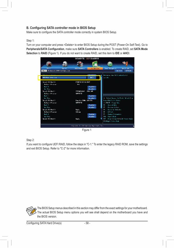
Configuring SATA Hard Drive(s) - 58 -
The BIOS Setup menus described in this section may differ from the exact settings for your motherboard. The actual BIOS Setup menu options you will see shall depend on the motherboard you have and the BIOS version.
B.ConfiguringSATAcontrollermodeinBIOSSetupMakesuretoconfiguretheSATAcontrollermodecorrectlyinsystemBIOSSetup.
Step 1: Turnonyourcomputerandpress<Delete>toenterBIOSSetupduringthePOST(Power-OnSelf-Test).GotoPeripherals\SATAConfiguration, make sure SATA Controllers is enabled. To create RAID, set SATA Mode Selection to RAID(Figure1).IfyoudonotwanttocreateRAID,setthisitemtoIDE or AHCI.
Step 2: IfyouwanttoconfigureUEFIRAID,followthestepsin"C-1."ToenterthelegacyRAIDROM,savethesettingsand exit BIOS Setup. Refer to "C-2" for more information.
Figure 1
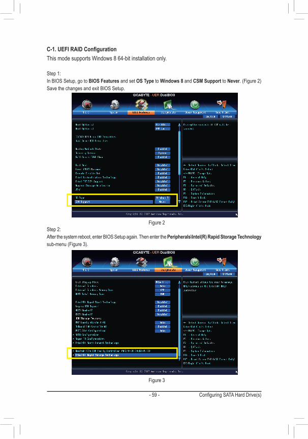
- 59 - Configuring SATA Hard Drive(s)
C-1.UEFIRAIDConfigurationThismodesupportsWindows864-bitinstallationonly.
Step 1:In BIOS Setup, go to BIOS Features and set OS Type to Windows 8 and CSM Support to Never.(Figure2)Save the changes and exit BIOS Setup.
Step 2:After the system reboot, enter BIOS Setup again. Then enter the Peripherals\Intel(R) Rapid Storage Technology sub-menu(Figure3).
Figure 2
Figure 3
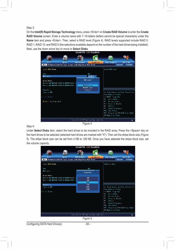
Configuring SATA Hard Drive(s) - 60 -
Step 3:On the Intel(R) Rapid Storage Technologymenu,press<Enter>onCreate RAID Volume to enter the Create RAID Volumescreen.Enteravolumenamewith1~16letters(letterscannotbespecialcharacters)undertheNameitemandpress<Enter>.Then,selectaRAIDlevel(Figure4).RAIDlevelssupportedincludeRAID0,RAID1,RAID10,andRAID5(theselectionsavailabledependonthenumberoftheharddrivesbeinginstalled).Next,usethedownarrowkeytomovetoSelect Disks.
Step 4:Under Select Disksitem,selecttheharddrivestobeincludedintheRAIDarray.Pressthe<Space>keyontheharddrivestobeselected(selectedharddrivesaremarkedwith"X").Thensetthestripeblocksize(Figure5).Thestripeblocksizecanbesetfrom4KBto128KB.Onceyouhaveselectedthestripeblocksize,setthe volume capacity.
Figure 4
Figure 5
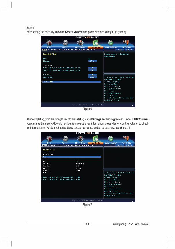
- 61 - Configuring SATA Hard Drive(s)
Step 5:After setting the capacity, move to Create Volumeandpress<Enter>tobegin.(Figure6)
After completing, you'll be brought back to the Intel(R) Rapid Storage Technology screen. Under RAID Volumes youcanseethenewRAIDvolume.Toseemoredetailedinformation,press<Enter>onthevolumetocheckforinformationonRAIDlevel,stripeblocksize,arrayname,andarraycapacity,etc.(Figure7)
Figure 6
Figure 7
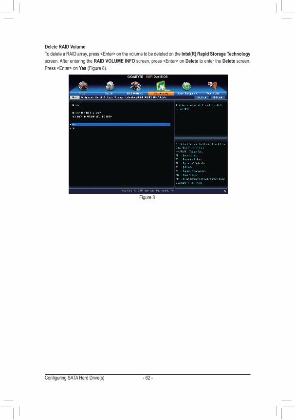
Configuring SATA Hard Drive(s) - 62 -
Delete RAID VolumeTodeleteaRAIDarray,press<Enter>onthevolumetobedeletedontheIntel(R) Rapid Storage Technology screen. After entering the RAID VOLUME INFOscreen,press<Enter>onDelete to enter the Delete screen. Press<Enter>onYes(Figure8).
Figure 8
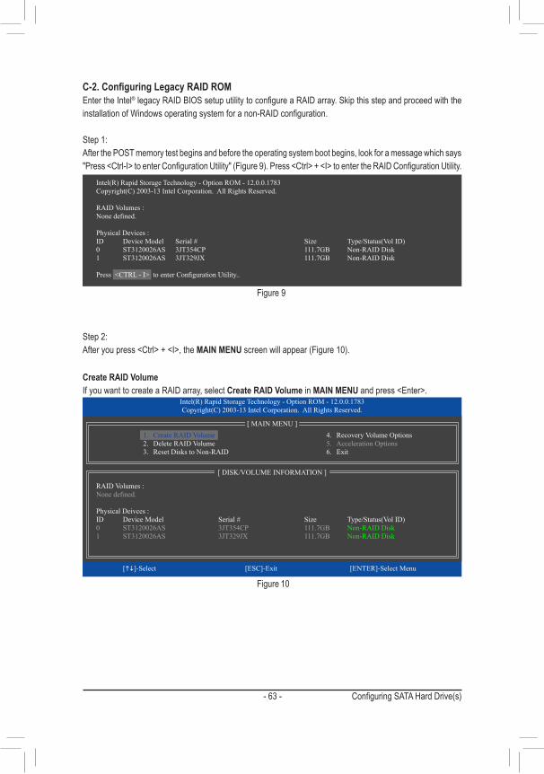
- 63 - Configuring SATA Hard Drive(s)
C-2.ConfiguringLegacyRAIDROMEnter the Intel®legacyRAIDBIOSsetuputilitytoconfigureaRAIDarray.SkipthisstepandproceedwiththeinstallationofWindowsoperatingsystemforanon-RAIDconfiguration.
Step 1:After the POST memory test begins and before the operating system boot begins, look for a message which says "Press<Ctrl-I>toenterConfigurationUtility"(Figure9).Press<Ctrl>+<I>toentertheRAIDConfigurationUtility.
Figure 9
Step 2:Afteryoupress<Ctrl>+<I>,theMAIN MENUscreenwillappear(Figure10).
Create RAID VolumeIf you want to create a RAID array, select Create RAID Volume in MAIN MENUandpress<Enter>.
Figure 10
Intel(R) Rapid Storage Technology - Option ROM - 12.0.0.1783Copyright(C) 2003-13 Intel Corporation. All Rights Reserved.
RAID Volumes :None defined.
Physical Devices :ID Device Model Serial # Size Type/Status(Vol ID)0 ST3120026AS 3JT354CP 111.7GB Non-RAID Disk1 ST3120026AS 3JT329JX 111.7GB Non-RAID Disk
Press <CTRL - I> to enter Configuration Utility..
Intel(R) Rapid Storage Technology - Option ROM - 12.0.0.1783Copyright(C) 2003-13 Intel Corporation. All Rights Reserved.
4. Recovery Volume Options5. Acceleration Options6. Exit
RAID Volumes :None defined.
Physical Deivces :ID Device Model Serial # Size Type/Status(Vol ID)0 ST3120026AS 3JT354CP 111.7GB Non-RAID Disk1 ST3120026AS 3JT329JX 111.7GB Non-RAID Disk
[hi]-Select [ESC]-Exit [ENTER]-Select Menu
[ DISK/VOLUME INFORMATION ]
[ MAIN MENU ]1. Create RAID Volume2. Delete RAID Volume3. Reset Disks to Non-RAID
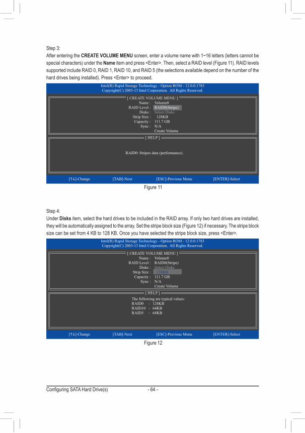
Configuring SATA Hard Drive(s) - 64 -
Step 3: After entering the CREATE VOLUME MENUscreen,enteravolumenamewith1~16letters(letterscannotbespecialcharacters)undertheNameitemandpress<Enter>.Then,selectaRAIDlevel(Figure11).RAIDlevelssupportedincludeRAID0,RAID1,RAID10,andRAID5(theselectionsavailabledependonthenumberoftheharddrivesbeinginstalled).Press<Enter>toproceed.
Step 4:Under Disks item, select the hard drives to be included in the RAID array. If only two hard drives are installed, theywillbeautomaticallyassignedtothearray.Setthestripeblocksize(Figure12)ifnecessary.Thestripeblocksizecanbesetfrom4KBto128KB.Onceyouhaveselectedthestripeblocksize,press<Enter>.
Figure 11
Figure 12
Intel(R) Rapid Storage Technology - Option ROM - 12.0.0.1783Copyright(C) 2003-13 Intel Corporation. All Rights Reserved.
RAID0: Stripes data (performance).
[hi]-Change [TAB]-Next [ESC]-Previous Menu [ENTER]-Select
[ HELP ]
Name : Volume0 RAID Level : RAID0(Stripe) Disks : Select Disks Strip Size : 128KB Capacity : 111.7 GB Sync : N/A Create Volume
[ CREATE VOLUME MENU ]
Intel(R) Rapid Storage Technology - Option ROM - 12.0.0.1783Copyright(C) 2003-13 Intel Corporation. All Rights Reserved.
The following are typical values: RAID0 - 128KB RAID10 - 64KB RAID5 - 64KB
[hi]-Change [TAB]-Next [ESC]-Previous Menu [ENTER]-Select
[ HELP ]
[ CREATE VOLUME MENU ] Name : Volume0 RAID Level : RAID0(Stripe) Disks : Select Disks Strip Size : 128KB Capacity : 111.7 GB Sync : N/A Create Volume
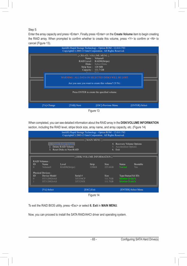
- 65 - Configuring SATA Hard Drive(s)
Step 5:Enterthearraycapacityandpress<Enter>.Finallypress<Enter>ontheCreate Volume item to begin creating theRAIDarray.Whenprompted toconfirmwhether tocreate thisvolume,press<Y> toconfirmor<N> tocancel(Figure13).
Whencompleted,youcanseedetailedinformationabouttheRAIDarrayintheDISK/VOLUME INFORMATION section,includingtheRAIDlevel,stripeblocksize,arrayname,andarraycapacity,etc.(Figure14)
ToexittheRAIDBIOSutility,press<Esc>orselect6. Exit in MAIN MENU.
Now,youcanproceedtoinstalltheSATARAID/AHCIdriverandoperatingsystem.
Figure 13
Figure 14
Intel(R) Rapid Storage Technology - Option ROM - 12.0.0.1783Copyright(C) 2003-13 Intel Corporation. All Rights Reserved.
Press ENTER to create the specified volume.
[hi]-Change [TAB]-Next [ESC]-Previous Menu [ENTER]-Select
[ HELP ]
Name : Volume0 RAID Level : RAID0(Stripe) Disks : Select Disks Strip Size : 128 MB Capacity : 111.7 GB Sync : N/A Create Volume
[ CREATE VOLUME MENU ]
WARNING : ALL DATA ON SELECTED DISKS WILL BE LOST.
Are you sure you want to create this volume? (Y/N) :
Intel(R) Rapid Storage Technology - Option ROM - 12.0.0.1783Copyright(C) 2003-13 Intel Corporation. All Rights Reserved.
RAID Volumes :ID Name Level Strip Size Status Bootable0 Volume0 RAID0(Stripe) 128KB 223.6GB Normal Yes
Physical Devices :ID Device Model Serial # Size Type/Status(Vol ID)0 ST3120026AS 3JT354CP 111.7GB Member Disk(0)1 ST3120026AS 3JT329JX 111.7GB Member Disk(0)
[hi]-Select [ESC]-Exit [ENTER]-Select Menu
[ DISK/VOLUME INFORMATION ]
[ MAIN MENU ]4. Recovery Volume Options5. Acceleration Options6. Exit
1. Create RAID Volume2. Delete RAID Volume3. Reset Disks to Non-RAID
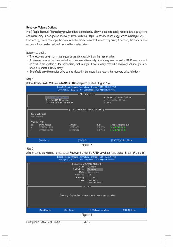
Configuring SATA Hard Drive(s) - 66 -
Recovery Volume OptionsIntel® Rapid Recover Technology provides data protection by allowing users to easily restore data and system operationusingadesignatedrecoverydrive.With theRapidRecoveryTechnology,whichemploysRAID1functionality,userscancopythedatafromthemasterdrivetotherecoverydrive;ifneeded,thedataontherecovery drive can be restored back to the master drive.
Before you begin: • The recovery drive must have equal or greater capacity than the master drive. • A recovery volume can be created with two hard drives only. A recovery volume and a RAID array cannot co-exist in the system at the same time, that is, if you have already created a recovery volume, you are unable to create a RAID array.
• Bydefault,onlythemasterdrivecanbeviewedintheoperatingsystem;therecoverydriveishidden.
Step 1:Select Create RAID Volume in MAIN MENUandpress<Enter>(Figure15).
Figure 15
Figure 16
Step 2:After entering the volume name, select Recovery under the RAID Levelitemandpress<Enter>(Figure16).
Intel(R) Rapid Storage Technology - Option ROM - 12.0.0.1783Copyright(C) 2003-13 Intel Corporation. All Rights Reserved.
Recovery: Copies data between a master and a recovery disk.
[hi]-Change [TAB]-Next [ESC]-Previous Menu [ENTER]-Select
[ HELP ]
Name : Volume0 RAID Level : Recovery Disks : Select Disks Strip Size : N/A Capacity : 111.7 GB Sync : Continuous Create Volume
[ CREATE VOLUME MENU ]
Intel(R) Rapid Storage Technology - Option ROM - 12.0.0.1783Copyright(C) 2003-13 Intel Corporation. All Rights Reserved.
RAID Volumes :None defined.
Physical Disks :IE Drive Model Serial # Size Type/Status(Vol ID)0 ST3120026AS 3JT354CP 111.7GB Non-RAID Disk1 ST3120026AS 3JT329JX 111.7GB Non-RAID Disk
[hi]-Select [ESC]-Exit [ENTER]-Select Menu
[ DISK/VOLUME INFORMATION ]
[ MAIN MENU ]4. Recovery Volume Options5. Acceleration Options6. Exit
1. Create RAID Volume2. Delete RAID Volume3. Reset Disks to Non-RAID
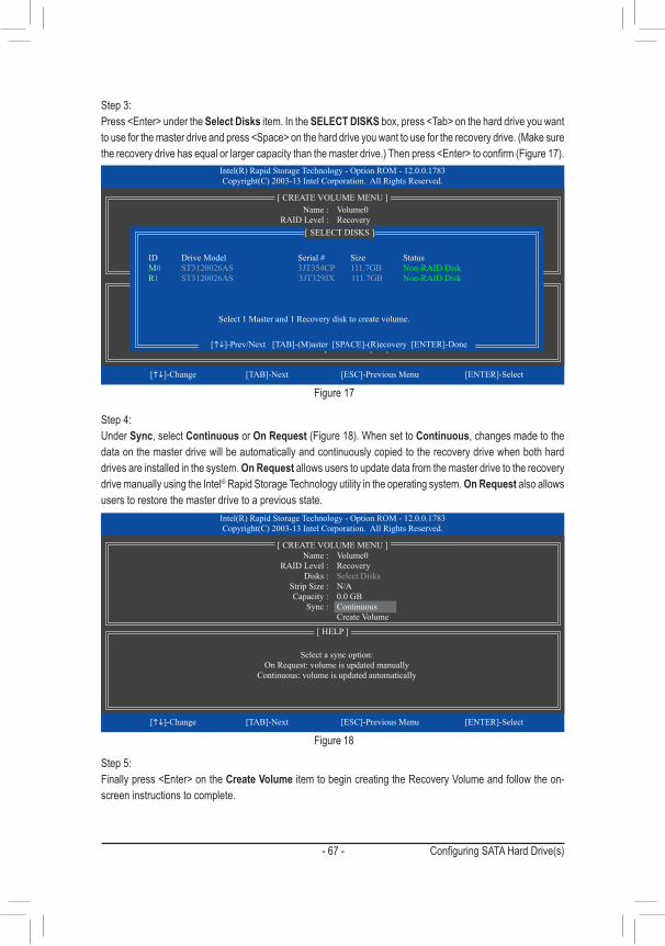
- 67 - Configuring SATA Hard Drive(s)
Figure 17
Step 3:Press<Enter>undertheSelect Disks item. In the SELECT DISKSbox,press<Tab>ontheharddriveyouwanttouseforthemasterdriveandpress<Space>ontheharddriveyouwanttousefortherecoverydrive.(Makesuretherecoverydrivehasequalorlargercapacitythanthemasterdrive.)Thenpress<Enter>toconfirm(Figure17).
Step 4:Under Sync, select Continuous or On Request(Figure18).WhensettoContinuous, changes made to the data on the master drive will be automatically and continuously copied to the recovery drive when both hard drives are installed in the system. On Request allows users to update data from the master drive to the recovery drive manually using the Intel® Rapid Storage Technology utility in the operating system. On Request also allows users to restore the master drive to a previous state.
Figure 18
Step 5:Finallypress<Enter>ontheCreate Volume item to begin creating the Recovery Volume and follow the on-screen instructions to complete.
Intel(R) Rapid Storage Technology - Option ROM - 12.0.0.1783Copyright(C) 2003-13 Intel Corporation. All Rights Reserved.
Choose the RAID level:RAID0: Stripes data (performance).RAID1: Mirrors data (redundancy).
Recovery: Copies data between a master and a recovery disk.RAID10: Mirrors data and stripes the mirror.
RAID5: Stripes data and parity.
[hi]-Change [TAB]-Next [ESC]-Previous Menu [ENTER]-Select
[ HELP ]
[ CREATE VOLUME MENU ] Name : Volume0 RAID Level : Recovery Disks : Select Disks Strip Size : 128KB Capacity : 223.6 GB Create Volume
[ SELECT DISKS ]
[hi]-Prev/Next [TAB]-(M)aster [SPACE]-(R)ecovery [ENTER]-Done
ID Drive Model Serial # Size StatusM0 ST3120026AS 3JT354CP 111.7GB Non-RAID DiskR1 ST3120026AS 3JT329JX 111.7GB Non-RAID Disk
Select 1 Master and 1 Recovery disk to create volume.
Intel(R) Rapid Storage Technology - Option ROM - 12.0.0.1783Copyright(C) 2003-13 Intel Corporation. All Rights Reserved.
Select a sync option:On Request: volume is updated manually
Continuous: volume is updated automatically
[hi]-Change [TAB]-Next [ESC]-Previous Menu [ENTER]-Select
[ HELP ]
Name : Volume0 RAID Level : Recovery Disks : Select Disks Strip Size : N/A Capacity : 0.0 GB Sync : Continuous Create Volume
[ CREATE VOLUME MENU ]
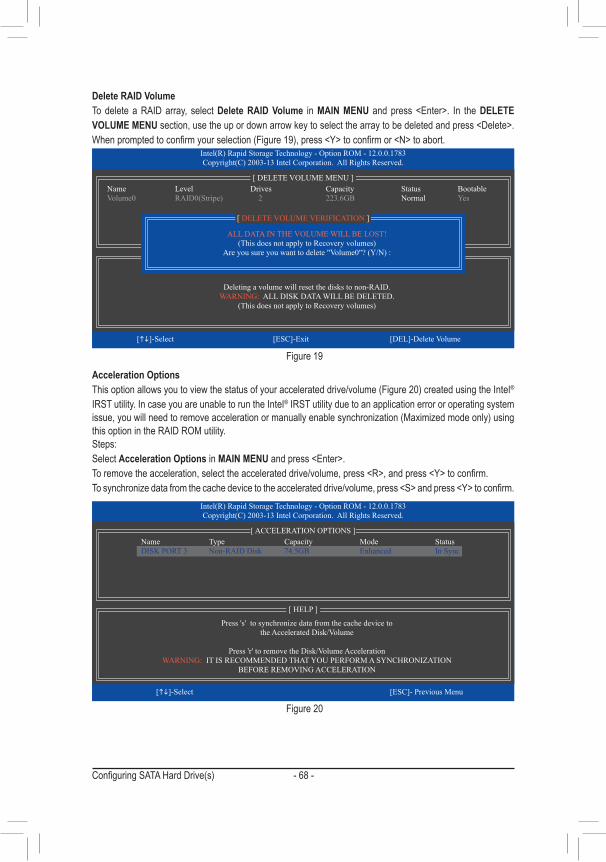
Configuring SATA Hard Drive(s) - 68 -
Delete RAID VolumeTo delete a RAID array, select Delete RAID Volume in MAIN MENU andpress<Enter>. In theDELETE VOLUME MENUsection,usetheupordownarrowkeytoselectthearraytobedeletedandpress<Delete>.Whenpromptedtoconfirmyourselection(Figure19),press<Y>toconfirmor<N>toabort.
Figure 19
Acceleration OptionsThisoptionallowsyoutoviewthestatusofyouraccelerateddrive/volume(Figure20)createdusingtheIntel® IRST utility. In case you are unable to run the Intel® IRST utility due to an application error or operating system issue,youwillneedtoremoveaccelerationormanuallyenablesynchronization(Maximizedmodeonly)usingthis option in the RAID ROM utility. Steps:Select Acceleration Options in MAIN MENUandpress<Enter>.Toremovetheacceleration,selecttheaccelerateddrive/volume,press<R>,andpress<Y>toconfirm.Tosynchronizedatafromthecachedevicetotheaccelerateddrive/volume,press<S>andpress<Y>toconfirm.
Figure 20
Intel(R) Rapid Storage Technology - Option ROM - 12.0.0.1783Copyright(C) 2003-13 Intel Corporation. All Rights Reserved.
Press 's' to synchronize data from the cache device tothe Accelerated Disk/Volume
Press 'r' to remove the Disk/Volume AccelerationWARNING: IT IS RECOMMENDED THAT YOU PERFORM A SYNCHRONIZATION
BEFORE REMOVING ACCELERATION
[hi]-Select [ESC]- Previous Menu
[ HELP ]
[ ACCELERATION OPTIONS ]Name Type Capacity Mode Status DISK PORT 3 Non-RAID Disk 74.5GB Enhanced In Sync
Intel(R) Rapid Storage Technology - Option ROM - 12.0.0.1783Copyright(C) 2003-13 Intel Corporation. All Rights Reserved.
Deleting a volume will reset the disks to non-RAID.WARNING: ALL DISK DATA WILL BE DELETED.
(This does not apply to Recovery volumes)
[hi]-Select [ESC]-Exit [DEL]-Delete Volume
[ HELP ]
[ DELETE VOLUME MENU ]Name Level Drives Capacity Status BootableVolume0 RAID0(Stripe) 2 223.6GB Normal Yes
ALL DATA IN THE VOLUME WILL BE LOST!(This does not apply to Recovery volumes)
Are you sure you want to delete "Volume0"? (Y/N) :
[ DELETE VOLUME VERIFICATION ]
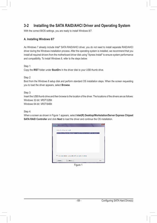
- 69 - Configuring SATA Hard Drive(s)
3-2 Installing the SATA RAID/AHCI Driver and Operating SystemWiththecorrectBIOSsettings,youarereadytoinstallWindows8/7.
A. Installing Windows 8/7
AsWindows7alreadyincludeIntel® SATA RAID/AHCI driver, you do not need to install separate RAID/AHCI driverduringtheWindowsinstallationprocess.Aftertheoperatingsystemisinstalled,werecommendthatyouinstallallrequireddriversfromthemotherboarddriverdiskusing"XpressInstall"toensuresystemperformanceandcompatibility.ToinstallWindows8,refertothestepsbelow:
Step 1: Copy the IRST folder under BootDrv in the driver disk to your USB thumb drive.
Step 2: BootfromtheWindows8setupdiskandperformstandardOSinstallationsteps.Whenthescreenrequestingyou to load the driver appears, select Browse.
Step 3: Insert the USB thumb drive and then browse to the location of the driver. The locations of the drivers are as follows:Windows32-bit:\iRST\32BitWindows64-bit:\iRST\64Bit
Step 4: WhenascreenasshowninFigure1appears,selectIntel(R) Desktop/Workstation/Server Express Chipset SATA RAID Controller and click Next to load the driver and continue the OS installation.
Figure 1
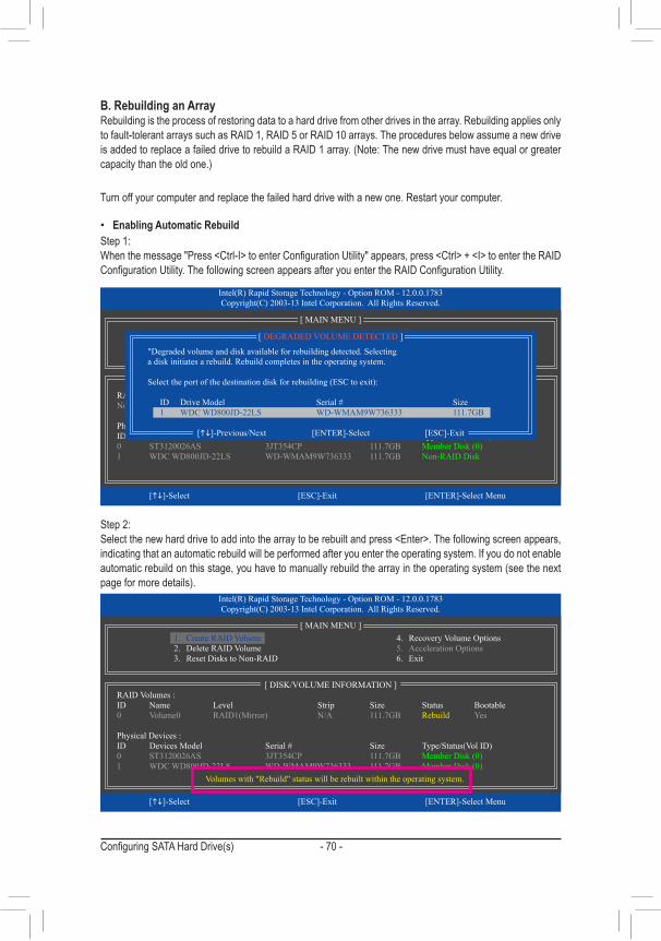
Configuring SATA Hard Drive(s) - 70 -
B. Rebuilding an ArrayRebuilding is the process of restoring data to a hard drive from other drives in the array. Rebuilding applies only to fault-tolerant arrays such as RAID 1, RAID 5 or RAID 10 arrays. The procedures below assume a new drive isaddedtoreplaceafaileddrivetorebuildaRAID1array.(Note:Thenewdrivemusthaveequalorgreatercapacitythantheoldone.)
Turn off your computer and replace the failed hard drive with a new one. Restart your computer.
• Enabling Automatic RebuildStep 1:Whenthemessage"Press<Ctrl-I>toenterConfigurationUtility"appears,press<Ctrl>+<I>toentertheRAIDConfigurationUtility.ThefollowingscreenappearsafteryouentertheRAIDConfigurationUtility.
Step 2:Selectthenewharddrivetoaddintothearraytoberebuiltandpress<Enter>.Thefollowingscreenappears,indicating that an automatic rebuild will be performed after you enter the operating system. If you do not enable automaticrebuildonthisstage,youhavetomanuallyrebuildthearrayintheoperatingsystem(seethenextpageformoredetails).
Intel(R) Rapid Storage Technology - Option ROM - 12.0.0.1783Copyright(C) 2003-13 Intel Corporation. All Rights Reserved.
3. Reset Disks to Non-RAID4. Exit
RAID Volumes :None defined.
Physical Disks :ID Drive Model Serial # Size Type/Status(Vol ID)0 ST3120026AS 3JT354CP 111.7GB Member Disk (0)1 WDC WD800JD-22LS WD-WMAM9W736333 111.7GB Non-RAID Disk
[hi]-Select [ESC]-Exit [ENTER]-Select Menu
[ DISK/VOLUME INFORMATION ]
[ MAIN MENU ]
1. Create RAID Volume2. Delete RAID Volume
[ DEGRADED VOLUME DETECTED ]
[hi]-Previous/Next [ENTER]-Select [ESC]-Exit
"Degraded volume and disk available for rebuilding detected. Selecting a disk initiates a rebuild. Rebuild completes in the operating system.
Select the port of the destination disk for rebuilding (ESC to exit):
ID Drive Model Serial # Size 1 WDC WD800JD-22LS WD-WMAM9W736333 111.7GB
Intel(R) Rapid Storage Technology - Option ROM - 12.0.0.1783Copyright(C) 2003-13 Intel Corporation. All Rights Reserved.
RAID Volumes :ID Name Level Strip Size Status Bootable0 Volume0 RAID1(Mirror) N/A 111.7GB Rebuild Yes
Physical Devices :ID Devices Model Serial # Size Type/Status(Vol ID)0 ST3120026AS 3JT354CP 111.7GB Member Disk (0)1 WDC WD800JD-22LS WD-WMAM9W736333 111.7GB Member Disk (0)
[hi]-Select [ESC]-Exit [ENTER]-Select Menu
[ DISK/VOLUME INFORMATION ]
Volumes with "Rebuild" status will be rebuilt within the operating system.
[ MAIN MENU ]4. Recovery Volume Options5. Acceleration Options6. Exit
1. Create RAID Volume2. Delete RAID Volume3. Reset Disks to Non-RAID
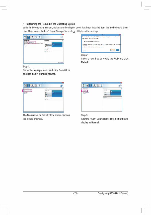
- 71 - Configuring SATA Hard Drive(s)
• Performing the Rebuild in the Operating SystemWhileintheoperatingsystem,makesurethechipsetdriverhasbeeninstalledfromthemotherboarddriverdisk. Then launch the Intel® Rapid Storage Technology utility from the desktop.
Step 1:Go to the Manage menu and click Rebuild to another disk in Manage Volume.
The Status item on the left of the screen displays the rebuild progress.
Step 2:Select a new drive to rebuild the RAID and click Rebuild.
Step 3:After the RAID 1 volume rebuilding, the Status will display as Normal.
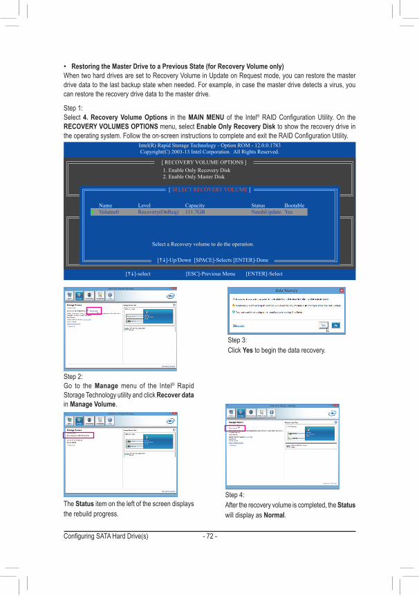
Configuring SATA Hard Drive(s) - 72 -
Step 2:Go to the Manage menu of the Intel® Rapid Storage Technology utility and click Recover data in Manage Volume.
The Status item on the left of the screen displays the rebuild progress.
Step 3:Click Yes to begin the data recovery.
Step 4:After the recovery volume is completed, the Status will display as Normal.
• Restoring the Master Drive to a Previous State (for Recovery Volume only)WhentwoharddrivesaresettoRecoveryVolumeinUpdateonRequestmode,youcanrestorethemasterdrive data to the last backup state when needed. For example, in case the master drive detects a virus, you can restore the recovery drive data to the master drive.
Step 1:Select 4. Recovery Volume Options in the MAIN MENU of the Intel®RAIDConfigurationUtility.On theRECOVERY VOLUMES OPTIONS menu, select Enable Only Recovery Disk to show the recovery drive in theoperatingsystem.Followtheon-screeninstructionstocompleteandexittheRAIDConfigurationUtility.
Intel(R) Rapid Storage Technology - Option ROM - 12.0.0.1783Copyright(C) 2003-13 Intel Corporation. All Rights Reserved.
Choose the RAID level:RAID0: Stripes data (performance).RAID1: Mirrors data (redundancy).
Recovery: Copies data between a master and a recovery disk.RAID10: Mirrors data and stripes the mirror.
RAID5: Stripes data and parity.
[hi]-select [ESC]-Previous Menu [ENTER]-Select
[ HELP ]
[ RECOVERY VOLUME OPTIONS ] 1. Enable Only Recovery Disk 2. Enable Only Master Disk
[ SELECT RECOVERY VOLUME ]
[hi]-Up/Down [SPACE]-Selects [ENTER]-Done
Name Level Capacity Status Bootable`Volume0 Recovery(OnReq) 111.7GB NeedsUpdate Yes
Select a Recovery volume to do the operation.
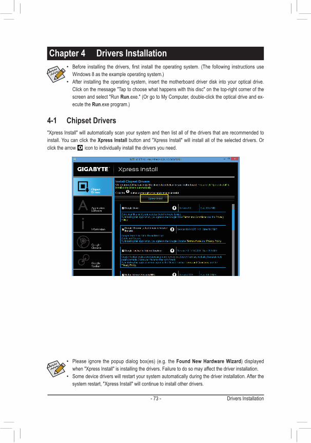
- 73 - Drivers Installation
4-1 Chipset Drivers
Chapter 4 Drivers Installation
"XpressInstall"willautomaticallyscanyoursystemandthenlistallofthedriversthatarerecommendedtoinstall. You can click the Xpress Installbuttonand"XpressInstall"will installalloftheselecteddrivers.Orclick the arrow icon to individually install the drivers you need.
• Before installing thedrivers, first install theoperating system. (The following instructionsuseWindows8astheexampleoperatingsystem.)
• After installing the operating system, insert the motherboard driver disk into your optical drive. Click on the message "Tap to choose what happens with this disc" on the top-right corner of the screen and select "Run Run.exe."(OrgotoMyComputer,double-clicktheopticaldriveandex-ecute the Run.exeprogram.)
• Please ignore thepopupdialogbox(es) (e.g. theFound New Hardware Wizard) displayedwhen"XpressInstall"isinstallingthedrivers.Failuretodosomayaffectthedriverinstallation.
• Some device drivers will restart your system automatically during the driver installation. After the systemrestart,"XpressInstall"willcontinuetoinstallotherdrivers.
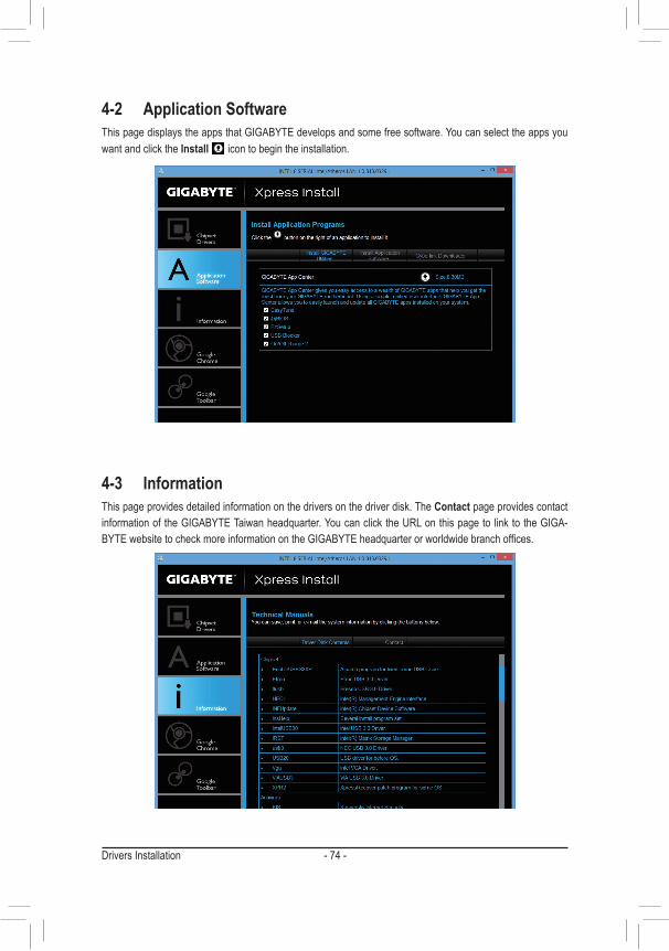
Drivers Installation - 74 -
4-2 Application SoftwareThis page displays the apps that GIGABYTE develops and some free software. You can select the apps you want and click the Install icon to begin the installation.
4-3 InformationThis page provides detailed information on the drivers on the driver disk. The Contact page provides contact information of the GIGABYTE Taiwan headquarter. You can click the URL on this page to link to the GIGA-BYTEwebsitetocheckmoreinformationontheGIGABYTEheadquarterorworldwidebranchoffices.
- 75 - Unique Features
5-1 BIOS Update Utilities
GIGABYTE motherboards provide two unique BIOS update tools, Q-Flash™ and @BIOS™. GIGABYTE Q-Flash and @BIOS are easy-to-use and allow you to update the BIOS without the need to enter MS-DOS mode. Additionally, this motherboard features the DualBIOS™ design, which enhances protection for the safety and stability of your computer by adding one more physical BIOS chip.
What is DualBIOS™?MotherboardsthatsupportDualBIOShavetwoBIOSonboard,amainBIOSandabackupBIOS.Normally,thesystem works on the main BIOS. However, if the main BIOS is corrupted or damaged, the backup BIOS will takeoveronthenextsystembootandcopytheBIOSfiletothemainBIOStoensurenormalsystemoperation.For the sake of system safety, users cannot update the backup BIOS manually.
What is Q-Flash™?WithQ-Flashyoucanupdate thesystemBIOSwithouthaving toenteroperatingsystems likeMS-DOSorWindowfirst.EmbeddedintheBIOS,theQ-FlashtoolfreesyoufromthehasslesofgoingthroughcomplicatedBIOSflashingprocess.
What is @BIOS™?@BIOSallowsyoutoupdatethesystemBIOSwhileintheWindowsenvironment.@BIOSwilldownloadthelatestBIOSfilefromthenearest@BIOSserversiteandupdatetheBIOS.
5-1-1 Updating the BIOS with the Q-Flash UtilityA. Before You Begin1. FromGIGABYTE'swebsite,downloadthelatestcompressedBIOSupdatefilethatmatchesyourmotherboard
model.2. ExtractthefileandsavethenewBIOSfile(e.g.Z87HD3.F1)toyourUSBflashdriveorharddrive.Note:The
USBflashdriveorharddrivemustuseFAT32/16/12filesystem.3. Restartthesystem.DuringthePOST,pressthe<End>keytoenterQ-Flash.Note:YoucanaccessQ-Flash
byeitherpressingthe<End>keyduringthePOSTorpressingthe<F8>keyinBIOSSetup.However,iftheBIOSupdatefileissavedtoaharddriveinRAID/AHCImodeoraharddriveattachedtoanindependentSATAcontroller,usethe<End>keyduringthePOSTtoaccessQ-Flash.
BecauseBIOSflashingispotentiallyrisky,pleasedoitwithcaution.InadequateBIOSflashingmayresult in system malfunction.
Chapter 5 Unique Features
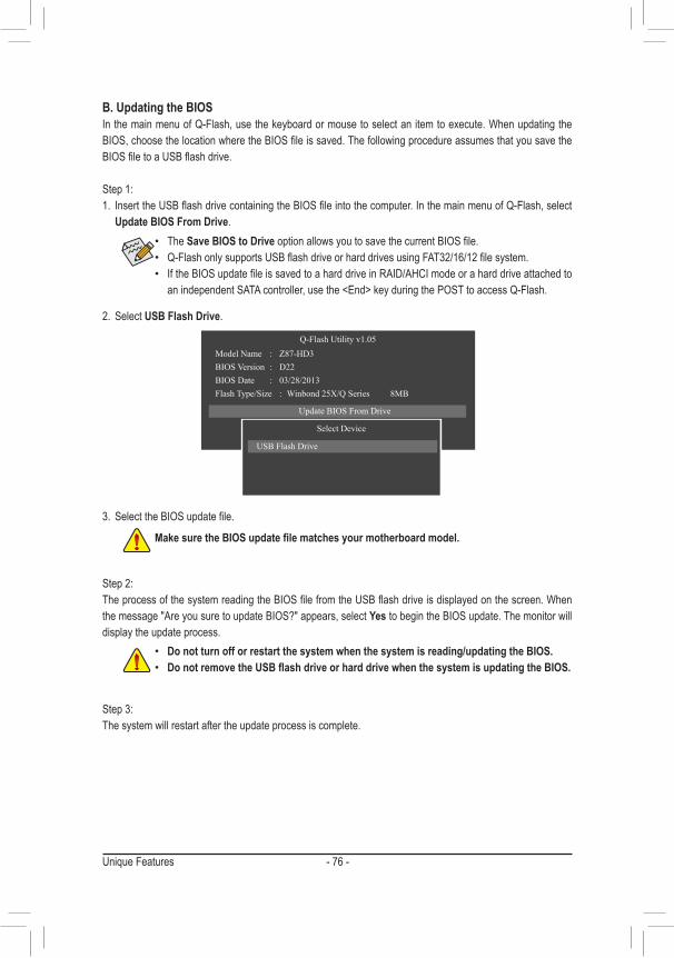
Unique Features - 76 -
B. Updating the BIOSInthemainmenuofQ-Flash,usethekeyboardormousetoselectanitemtoexecute.WhenupdatingtheBIOS,choosethelocationwheretheBIOSfileissaved.ThefollowingprocedureassumesthatyousavetheBIOSfiletoaUSBflashdrive.
Step 1:1. InserttheUSBflashdrivecontainingtheBIOSfileintothecomputer.InthemainmenuofQ-Flash,select
Update BIOS From Drive.
Step 2: TheprocessofthesystemreadingtheBIOSfilefromtheUSBflashdriveisdisplayedonthescreen.Whenthe message "Are you sure to update BIOS?" appears, select Yes to begin the BIOS update. The monitor will display the update process.
Step 3: The system will restart after the update process is complete.
2. Select USB Flash Drive.
3. SelecttheBIOSupdatefile.
• The Save BIOS to DriveoptionallowsyoutosavethecurrentBIOSfile. • Q-FlashonlysupportsUSBflashdriveorharddrivesusingFAT32/16/12filesystem. • IftheBIOSupdatefileissavedtoaharddriveinRAID/AHCImodeoraharddriveattachedtoanindependentSATAcontroller,usethe<End>keyduringthePOSTtoaccessQ-Flash.
MakesuretheBIOSupdatefilematchesyourmotherboardmodel.
• Do not turn off or restart the system when the system is reading/updating the BIOS. • DonotremovetheUSBflashdriveorharddrivewhenthesystemisupdatingtheBIOS.
Q-Flash Utility v1.05Model Name : Z87-HD3BIOS Version : D22BIOS Date : 03/28/2013Flash Type/Size : Winbond 25X/Q Series 8MB
Update BIOS From DriveSave BIOS to Drive
Return to BIOS setupSelect Device
USB Flash Drive
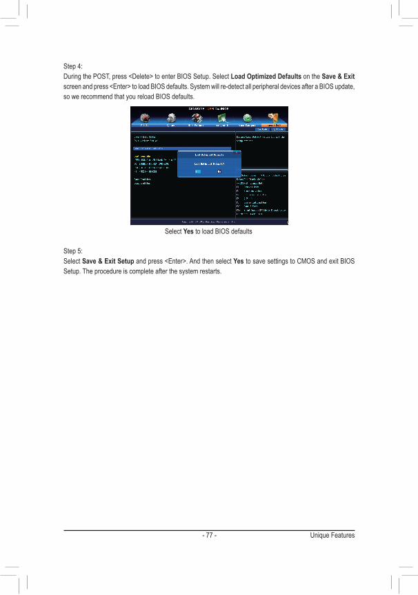
- 77 - Unique Features
Select Yes to load BIOS defaults
Step 4:DuringthePOST,press<Delete>toenterBIOSSetup.SelectLoad Optimized Defaults on the Save & Exit screenandpress<Enter>toloadBIOSdefaults.Systemwillre-detectallperipheraldevicesafteraBIOSupdate,so we recommend that you reload BIOS defaults.
Step 5:Select Save & Exit Setupandpress<Enter>.AndthenselectYes to save settings to CMOS and exit BIOS Setup. The procedure is complete after the system restarts.
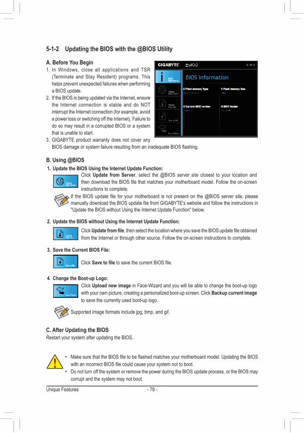
Unique Features - 78 -
5-1-2 Updating the BIOS with the @BIOS Utility
A. Before You Begin1. In Windows, close all applications and TSR
(Terminate and Stay Resident) programs. Thishelps prevent unexpected failures when performing a BIOS update.
2. If the BIOS is being updated via the Internet, ensure the Internet connection is stable and do NOTinterrupttheInternetconnection(forexample,avoidapowerlossorswitchingofftheInternet).Failuretodo so may result in a corrupted BIOS or a system that is unable to start.
3. GIGABYTE product warranty does not cover any BIOSdamageorsystemfailureresultingfromaninadequateBIOSflashing.
B. Using @BIOS
• MakesurethattheBIOSfiletobeflashedmatchesyourmotherboardmodel.UpdatingtheBIOSwithanincorrectBIOSfilecouldcauseyoursystemnottoboot.
• Do not turn off the system or remove the power during the BIOS update process, or the BIOS may corrupt and the system may not boot.
If theBIOSupdatefile foryourmotherboard isnotpresenton the@BIOSserversite,pleasemanuallydownloadtheBIOSupdatefilefromGIGABYTE'swebsiteandfollowtheinstructionsin"Update the BIOS without Using the Internet Update Function" below.
Supported image formats include jpg, bmp, and gif.
C. After Updating the BIOSRestart your system after updating the BIOS.
1. Update the BIOS Using the Internet Update Function:Click Update from Server, select the @BIOS server site closest to your location and thendownloadtheBIOSfilethatmatchesyourmotherboardmodel.Followtheon-screeninstructions to complete.
2. Update the BIOS without Using the Internet Update Function:Click Updatefromfile,thenselectthelocationwhereyousavetheBIOSupdatefileobtainedfrom the Internet or through other source. Follow the on-screen instructions to complete.
3. Save the Current BIOS File:
Click SavetofiletosavethecurrentBIOSfile.
4. Change the Boot-up Logo:Click Upload new imageinFace-Wizardandyouwillbeabletochangetheboot-uplogowithyourownpicture,creatingapersonalizedboot-upscreen.ClickBackup current image to save the currently used boot-up logo.
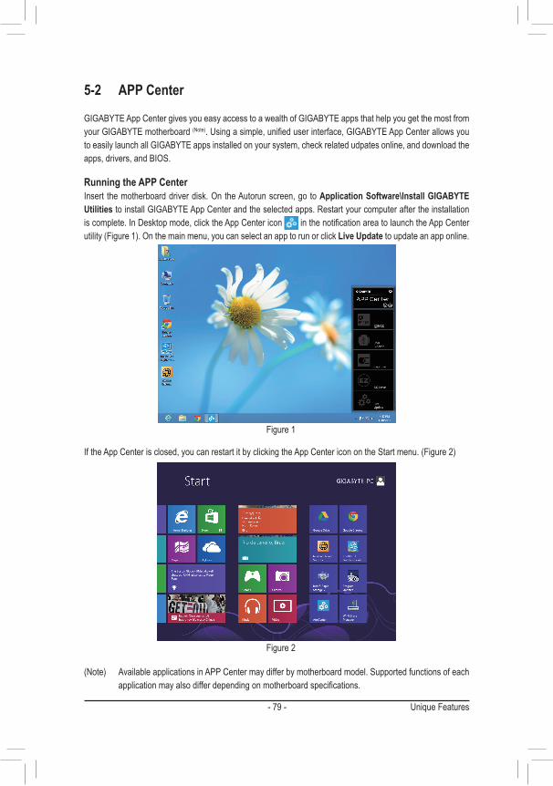
- 79 - Unique Features
5-2 APP Center
GIGABYTE App Center gives you easy access to a wealth of GIGABYTE apps that help you get the most from your GIGABYTE motherboard (Note).Usingasimple,unifieduserinterface,GIGABYTEAppCenterallowsyouto easily launch all GIGABYTE apps installed on your system, check related udpates online, and download the apps, drivers, and BIOS.
Running the APP CenterInsert the motherboard driver disk. On the Autorun screen, go to Application Software\Install GIGABYTE Utilities to install GIGABYTE App Center and the selected apps. Restart your computer after the installation is complete. In Desktop mode, click the App Center icon inthenotificationareatolaunchtheAppCenterutility(Figure1).Onthemainmenu,youcanselectanapptorunorclickLive Update to update an app online.
IftheAppCenterisclosed,youcanrestartitbyclickingtheAppCentericonontheStartmenu.(Figure2)
(Note) AvailableapplicationsinAPPCentermaydifferbymotherboardmodel.Supportedfunctionsofeachapplicationmayalsodifferdependingonmotherboardspecifications.
Figure 2
Figure 1
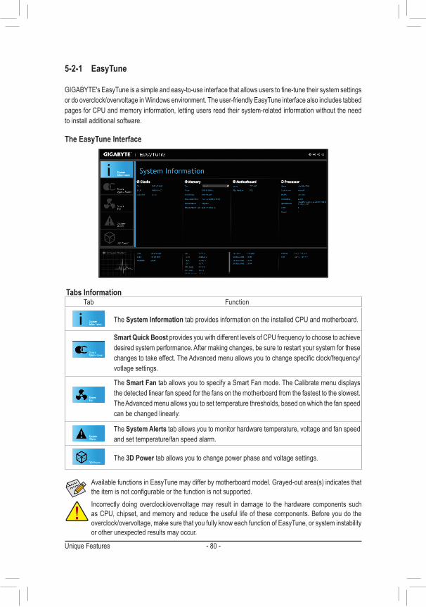
Unique Features - 80 -
5-2-1 EasyTune
GIGABYTE'sEasyTuneisasimpleandeasy-to-useinterfacethatallowsuserstofine-tunetheirsystemsettingsordooverclock/overvoltageinWindowsenvironment.Theuser-friendlyEasyTuneinterfacealsoincludestabbedpages for CPU and memory information, letting users read their system-related information without the need to install additional software.
The EasyTune Interface
Tabs InformationTab Function
The System Information tab provides information on the installed CPU and motherboard.
Smart Quick Boost provides you with different levels of CPU frequency to choose to achieve desired system performance. After making changes, be sure to restart your system for these changestotakeeffect.TheAdvancedmenuallowsyoutochangespecificclock/frequency/votlage settings.
The Smart Fan tab allows you to specify a Smart Fan mode. The Calibrate menu displays the detected linear fan speed for the fans on the motherboard from the fastest to the slowest. The Advanced menu allows you to set temperature thresholds, based on which the fan speed can be changed linearly.
The System Alerts tab allows you to monitor hardware temperature, voltage and fan speed and set temperature/fan speed alarm.
The 3D Power tab allows you to change power phase and voltage settings.
Incorrectly doing overclock/overvoltage may result in damage to the hardware components such as CPU, chipset, and memory and reduce the useful life of these components. Before you do the overclock/overvoltage, make sure that you fully know each function of EasyTune, or system instability or other unexpected results may occur.
AvailablefunctionsinEasyTunemaydifferbymotherboardmodel.Grayed-outarea(s)indicatesthattheitemisnotconfigurableorthefunctionisnotsupported.
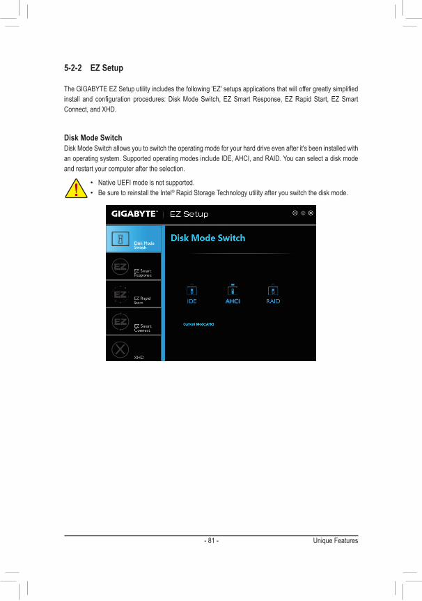
- 81 - Unique Features
5-2-2 EZ Setup
TheGIGABYTEEZSetuputilityincludesthefollowing'EZ'setupsapplicationsthatwilloffergreatlysimplifiedinstall and configuration procedures:DiskModeSwitch,EZSmartResponse,EZRapidStart, EZSmartConnect,andXHD.
Disk Mode SwitchDisk Mode Switch allows you to switch the operating mode for your hard drive even after it's been installed with an operating system. Supported operating modes include IDE, AHCI, and RAID. You can select a disk mode and restart your computer after the selection.
• NativeUEFImodeisnotsupported. • Be sure to reinstall the Intel® Rapid Storage Technology utility after you switch the disk mode.
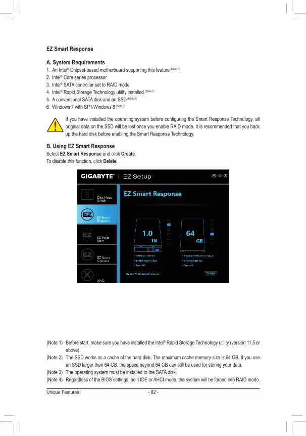
Unique Features - 82 -
EZ Smart Response
A. System Requirements1. An Intel® Chipset-based motherboard supporting this feature(Note1)
2. Intel® Core series processor3. Intel® SATA controller set to RAID mode4. Intel® Rapid Storage Technology utility installed (Note1)5. A conventional SATA disk and an SSD(Note2)
6. Windows7withSP1/Windows8(Note3)
B. Using EZ Smart ResponseSelect EZ Smart Response and click Create. To disable this function, click Delete.
IfyouhaveinstalledtheoperatingsystembeforeconfiguringtheSmartResponseTechnology,alloriginal data on the SSD will be lost once you enable RAID mode. It is recommended that you back up the hard disk before enabling the Smart Response Technology.
(Note1) Beforestart,makesureyouhaveinstalledtheIntel®RapidStorageTechnologyutility(version11.5orabove).
(Note2) TheSSDworksasacacheoftheharddisk.Themaximumcachememorysizeis64GB.Ifyouusean SSD larger than 64 GB, the space beyond 64 GB can still be used for storing your data.
(Note3) TheoperatingsystemmustbeinstalledtotheSATAdisk.(Note4) RegardlessoftheBIOSsettings,beitIDEorAHCImode,thesystemwillbeforcedintoRAIDmode.
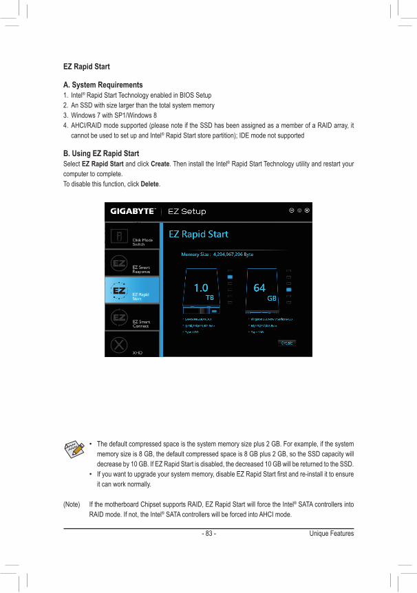
- 83 - Unique Features
EZ Rapid Start
A. System Requirements1. Intel® Rapid Start Technology enabled in BIOS Setup2. AnSSDwithsizelargerthanthetotalsystemmemory3. Windows7withSP1/Windows84. AHCI/RAIDmodesupported(pleasenoteiftheSSDhasbeenassignedasamemberofaRAIDarray,it
cannot be used to set up and Intel®RapidStartstorepartition);IDEmodenotsupported
B. Using EZ Rapid StartSelect EZ Rapid Start and click Create. Then install the Intel® Rapid Start Technology utility and restart your computer to complete. To disable this function, click Delete.
• Thedefaultcompressedspaceisthesystemmemorysizeplus2GB.Forexample,ifthesystemmemorysizeis8GB,thedefaultcompressedspaceis8GBplus2GB,sotheSSDcapacitywilldecrease by 10 GB. If EZ Rapid Start is disabled, the decreased 10 GB will be returned to the SSD.
• Ifyouwanttoupgradeyoursystemmemory,disableEZRapidStartfirstandre-installittoensureit can work normally.
(Note) IfthemotherboardChipsetsupportsRAID,EZRapidStartwillforcetheIntel® SATA controllers into RAID mode. If not, the Intel® SATA controllers will be forced into AHCI mode.
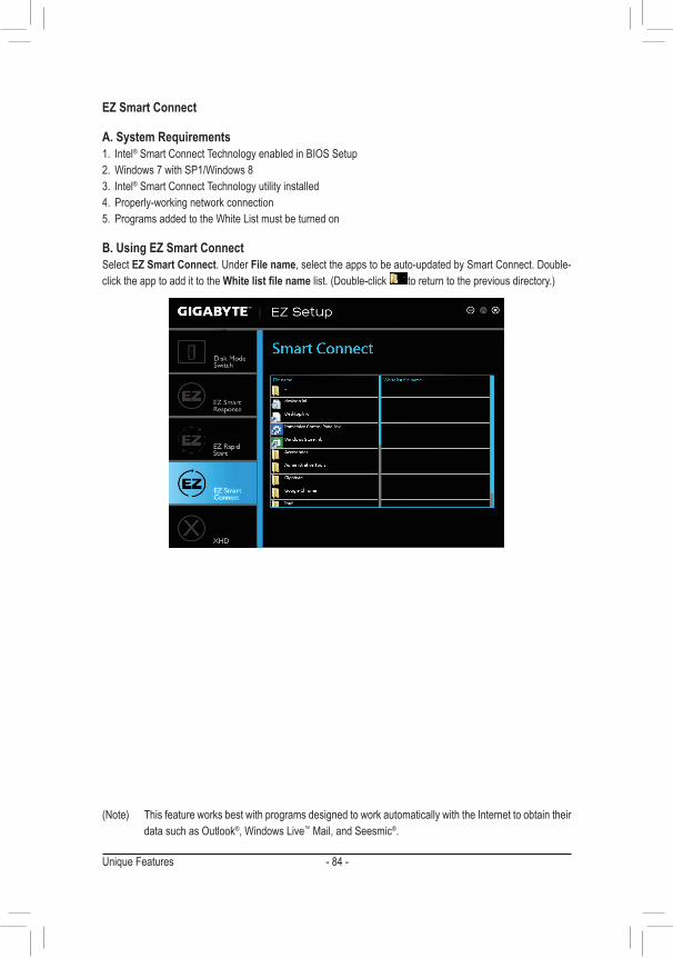
Unique Features - 84 -
EZ Smart Connect
A. System Requirements1. Intel® Smart Connect Technology enabled in BIOS Setup2. Windows7withSP1/Windows83. Intel® Smart Connect Technology utility installed4. Properly-working network connection5. ProgramsaddedtotheWhiteListmustbeturnedon
B. Using EZ Smart ConnectSelect EZ Smart Connect. Under File name, select the apps to be auto-updated by Smart Connect. Double-click the app to add it to the Whitelistfilenamelist.(Double-click toreturntothepreviousdirectory.)
(Note) ThisfeatureworksbestwithprogramsdesignedtoworkautomaticallywiththeInternettoobtaintheirdata such as Outlook®,WindowsLive™ Mail, and Seesmic®.
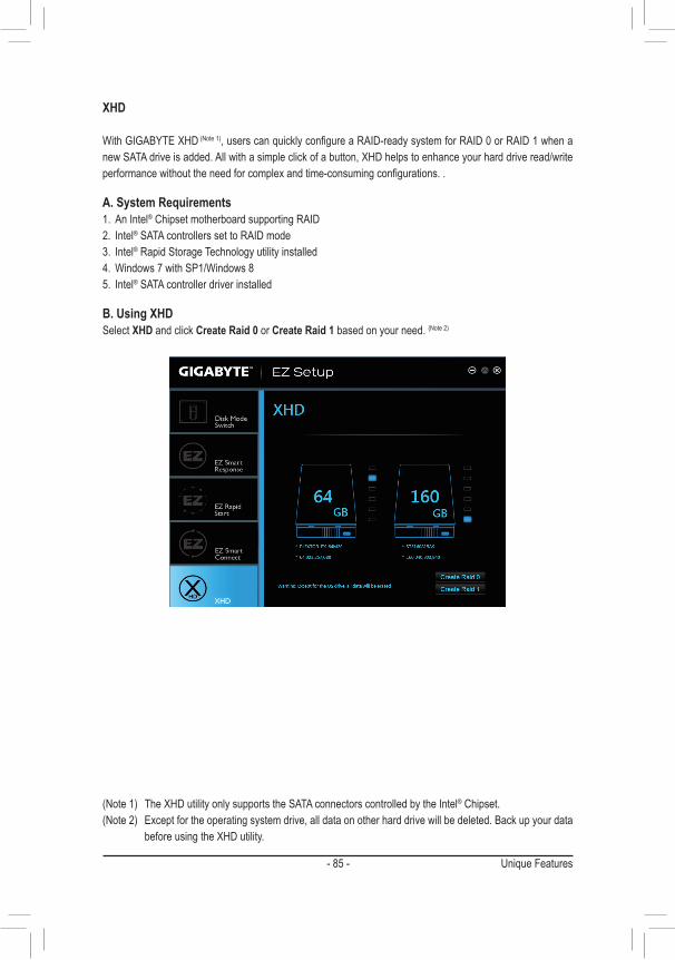
- 85 - Unique Features
XHD
WithGIGABYTEXHD(Note1),userscanquicklyconfigureaRAID-readysystemforRAID0orRAID1whenanewSATAdriveisadded.Allwithasimpleclickofabutton,XHDhelpstoenhanceyourharddriveread/writeperformancewithouttheneedforcomplexandtime-consumingconfigurations..
A. System Requirements1. An Intel® Chipset motherboard supporting RAID2. Intel® SATA controllers set to RAID mode3. Intel® Rapid Storage Technology utility installed4. Windows7withSP1/Windows85. Intel® SATA controller driver installed
B. Using XHDSelect XHD and click Create Raid 0 or Create Raid 1 based on your need. (Note2)
(Note1) TheXHDutilityonlysupportstheSATAconnectorscontrolledbytheIntel® Chipset.(Note2) Exceptfortheoperatingsystemdrive,alldataonotherharddrivewillbedeleted.Backupyourdata
beforeusingtheXHDutility.
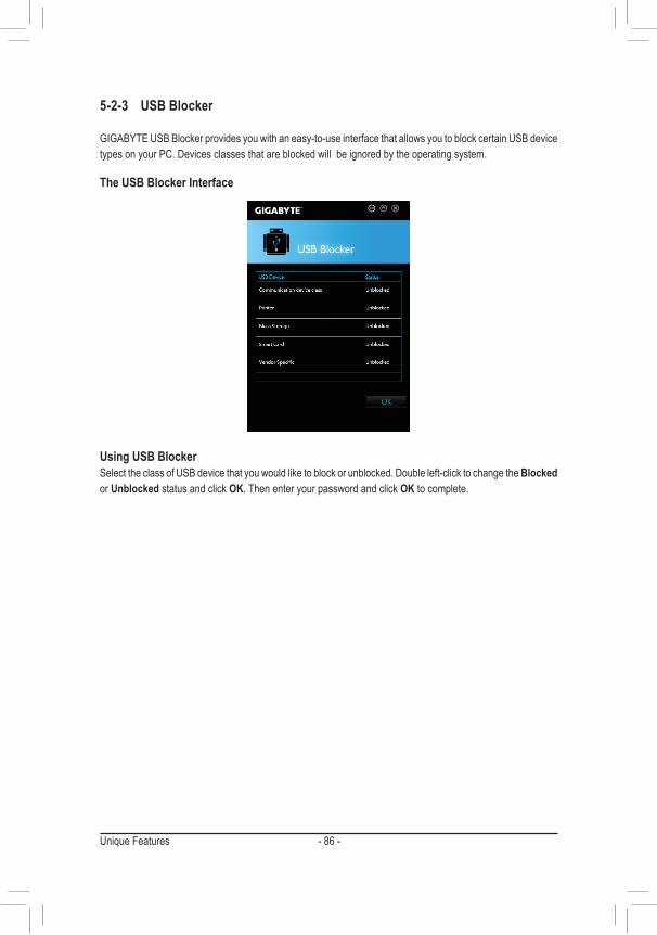
Unique Features - 86 -
5-2-3 USB Blocker
GIGABYTE USB Blocker provides you with an easy-to-use interface that allows you to block certain USB device types on your PC. Devices classes that are blocked will be ignored by the operating system.
The USB Blocker Interface
Using USB BlockerSelect the class of USB device that you would like to block or unblocked. Double left-click to change the Blocked or Unblocked status and click OK. Then enter your password and click OK to complete.
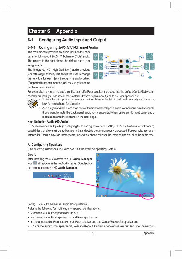
- 87 - Appendix
6-1-1 Configuring2/4/5.1/7.1-ChannelAudioThe motherboard provides six audio jacks on the back panelwhichsupport2/4/5.1/7.1-channel(Note)audio.The picture to the right shows the default audio jack assignments. The integratedHD (HighDefinition) audio providesjack retasking capability that allows the user to change the function for each jack through the audio driver. (Supportedfunctionsforeachjackmayvarybasedonhardwarespecification.)Forexample,ina4-channelaudioconfiguration,ifaRearspeakerispluggedintothedefaultCenter/Subwooferspeaker out jack, you can retask the Center/Subwoofer speaker out jack to be Rear speaker out.
6-1 ConfiguringAudioInputandOutput
HighDefinitionAudio(HDAudio)HDAudioincludesmultiplehighqualitydigital-to-analogconverters(DACs).HDAudiofeaturesmultistreamingcapabilitiesthatallowmultipleaudiostreams(inandout)tobesimultaneouslyprocessed.Forexample,userscanlisten to MP3 music, have an Internet chat, make a telephone call over the Internet, and etc. all at the same time.
A.ConfiguringSpeakers(ThefollowinginstructionsuseWindows8astheexampleoperatingsystem.)
• Toinstallamicrophone,connectyourmicrophonetotheMicinjackandmanuallyconfigurethejack for microphone functionality.
• Audio signals will be present on both of the front and back panel audio connections simultaneously. Ifyouwanttomutethebackpanelaudio(onlysupportedwhenusinganHDfrontpanelaudiomodule),refertoinstructionsonthenextpage.
Center/Subwoofer Speaker Out
Line In
Rear Speaker Out Front Speaker Out
Mic InSide Speaker Out
(Note) 2/4/5.1/7.1-ChannelAudioConfigurations:Refertothefollowingformulti-channelspeakerconfigurations. • 2-channel audio: Headphone or Line out. • 4-channel audio: Front speaker out and Rear speaker out. • 5.1-channel audio: Front speaker out, Rear speaker out, and Center/Subwoofer speaker out. • 7.1-channel audio: Front speaker out, Rear speaker out, Center/Subwoofer speaker out, and Side speaker out.
Chapter 6 Appendix
Step 1:After installing the audio driver, the HD Audio Manager icon willappearinthenotificationarea.Double-clickthe icon to access the HD Audio Manager.
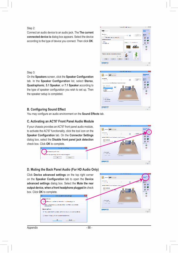
Appendix - 88 -
Step 2:Connect an audio device to an audio jack. The The current connected device is dialog box appears. Select the device according to the type of device you connect. Then click OK.
Step 3:On the Speakers screen, click the SpeakerConfiguration tab. In the Speaker Configuration list, select Stereo, Quadraphonic, 5.1 Speaker, or 7.1 Speaker according to thetypeofspeakerconfigurationyouwishtosetup.Thenthe speaker setup is completed.
If your chassis provides an AC'97 front panel audio module, to activate the AC'97 functionality, click the tool icon on the SpeakerConfiguration tab. On the Connector Settings dialog box, select the Disable front panel jack detection check box. Click OK to complete.
Click Device advanced settings on the top right corner on the SpeakerConfiguration tab to open the Device advanced settings dialog box. Select the Mute the rear output device, when a front headphone plugged in check box. Click OK to complete.
B.ConfiguringSoundEffectYoumayconfigureanaudioenvironmentontheSound Effects tab.
C. Activating an AC'97 Front Panel Audio Module
D. Muting the Back Panel Audio (For HD Audio Only)
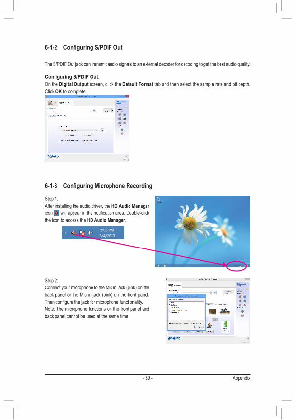
- 89 - Appendix
6-1-2 ConfiguringS/PDIFOut
ConfiguringS/PDIFOut:On the Digital Output screen, click the Default Format tab and then select the sample rate and bit depth. Click OK to complete.
The S/PDIF Out jack can transmit audio signals to an external decoder for decoding to get the best audio quality.
6-1-3 ConfiguringMicrophoneRecording
Step 1:After installing the audio driver, the HD Audio Manager icon willappearinthenotificationarea.Double-clickthe icon to access the HD Audio Manager.
Step 2:ConnectyourmicrophonetotheMicinjack(pink)onthebackpanelortheMicinjack(pink)onthefrontpanel.Thenconfigurethejackformicrophonefunctionality.Note:Themicrophonefunctionsonthefrontpanelandback panel cannot be used at the same time.
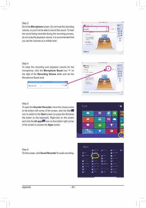
Appendix - 90 -
Step 3:Go to the Microphone screen. Do not mute the recording volume, or you'll not be able to record the sound. To hear the sound being recorded during the recording process, do not mute the playback volume. It is recommended that you set the volumes at a middle level.
Step 4:To raise the recording and playback volume for the microphone, click the Microphone Boost icon on the right of the Recording Volume slider and set the Microphone Boost level.
Step 5:To open the Sounder Recorder, move the mouse cursor to the bottom left corner of the screen, click the Start icon to switch to the Startscreen(orpresstheWindowsthebuttonon thekeyboard).Right-clickon thescreenand click the All apps icon on the bottom right corner of the screen to access the Apps screen
Step 6:On this screen, click Sound Recorder for audio recording.
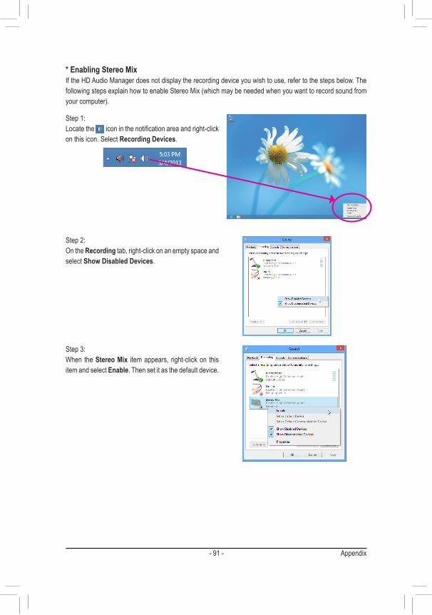
- 91 - Appendix
Step 1:Locate the iconinthenotificationareaandright-clickon this icon. Select Recording Devices.
* Enabling Stereo MixIf the HD Audio Manager does not display the recording device you wish to use, refer to the steps below. The followingstepsexplainhowtoenableStereoMix(whichmaybeneededwhenyouwanttorecordsoundfromyourcomputer).
Step 2:On the Recording tab, right-click on an empty space and select Show Disabled Devices.
Step 3:When theStereo Mix item appears, right-click on this item and select Enable. Then set it as the default device.
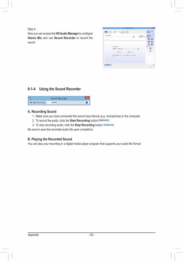
Appendix - 92 -
Step 4:NowyoucanaccesstheHD Audio ManagertoconfigureStereo Mix and use Sound Recorder to record the sound.
6-1-4 Using the Sound Recorder
A. Recording Sound1. Makesureyouhaveconnectedthesoundinputdevice(e.g.microphone)tothecomputer.2. To record the audio, click the Start Recording button .3. To stop recording audio, click the Stop Recording button .
Besuretosavetherecordedaudiofileuponcompletion.
B. Playing the Recorded SoundYoucanplayyourrecordinginadigitalmediaplayerprogramthatsupportsyouraudiofileformat.
- 93 - Appendix
6-2 Troubleshooting
6-2-1 Frequently Asked Questions To read more FAQs for your motherboard, please go to the Support & Downloads\FAQ page on GIGABYTE's website.
Q:Whyisthelightofmykeyboard/opticalmousestillonafterthecomputershutsdown?A: Some motherboards provide a small amount of standby power after the computer shuts down and that's why the light is
still on.
Q: How do I clear the CMOS values?A: FormotherboardsthathaveaClearCMOSbutton,pressthisbuttontocleartheCMOSvalues(beforedoingthis,please
turnoffthecomputerandunplugthepowercord).FormotherboardsthathaveaClearCMOSjumper,refertotheinstruc-tions in Chapter 1 to short the jumper to clear the CMOS values. If your board doesn't have this jumper/button, refer to the instructions on the motherboard battery in Chapter 1. You can temporarily remove the battery from the battery holder to stop supplying power to the CMOS, which will clear the CMOS values after about one minute.
Q:WhydoIstillgetaweaksoundeventhoughIhaveturnedmyspeakertothemaximumvolume?A: Makesureyourspeakerisequippedwithaninternalamplifier.Ifnot,tryaspeakerwithpower/amplifier.
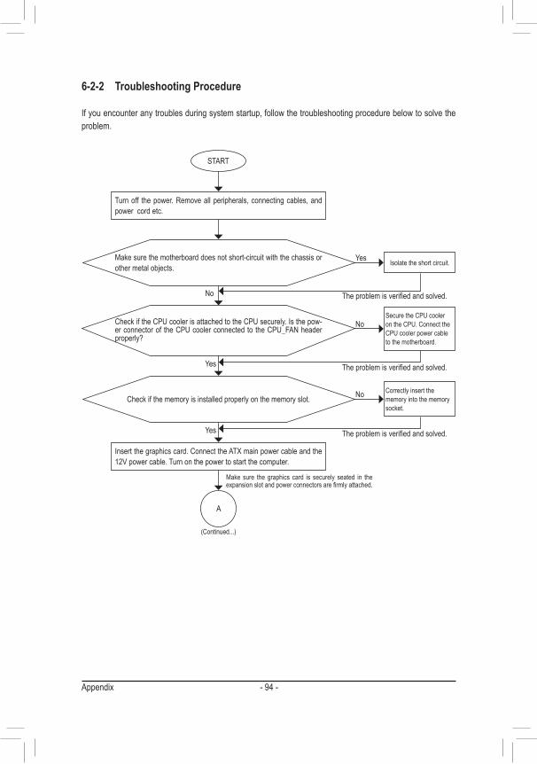
Appendix - 94 -
6-2-2 Troubleshooting Procedure
If you encounter any troubles during system startup, follow the troubleshooting procedure below to solve the problem.
START
A
Turn off the power. Remove all peripherals, connecting cables, and power cord etc.
Isolate the short circuit.
Secure the CPU cooler on the CPU. Connect the CPU cooler power cable to the motherboard.
Correctly insert the memory into the memory socket.
(Continued...)
Yes
Theproblemisverifiedandsolved.
Theproblemisverifiedandsolved.
Theproblemisverifiedandsolved.
No
No
No
Yes
Yes
Insertthegraphicscard.ConnecttheATXmainpowercableandthe12V power cable. Turn on the power to start the computer.
Make sure the motherboard does not short-circuit with the chassis or other metal objects.
Check if the CPU cooler is attached to the CPU securely. Is the pow-erconnectorof theCPUcoolerconnectedtotheCPU_FANheaderproperly?
Check if the memory is installed properly on the memory slot.
Make sure the graphics card is securely seated in the expansionslotandpowerconnectorsarefirmlyattached.
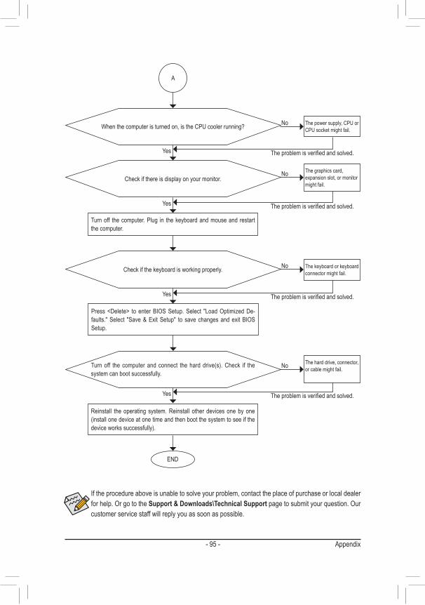
- 95 - Appendix
If the procedure above is unable to solve your problem, contact the place of purchase or local dealer for help. Or go to the Support & Downloads\Technical Support page to submit your question. Our customer service staff will reply you as soon as possible.
The power supply, CPU or CPU socket might fail.
The keyboard or keyboard connector might fail.
END
A
Turn off the computer. Plug in the keyboard and mouse and restart the computer.
The graphics card, expansion slot, or monitor might fail.
The hard drive, connector, or cable might fail.
No
Theproblemisverifiedandsolved.
Theproblemisverifiedandsolved.
Theproblemisverifiedandsolved.
No
No
Yes
Yes
Yes
Reinstall the operating system. Reinstall other devices one by one (installonedeviceatonetimeandthenbootthesystemtoseeifthedeviceworkssuccessfully).
Press<Delete> to enterBIOSSetup.Select "LoadOptimizedDe-faults." Select "Save & Exit Setup" to save changes and exit BIOS Setup.
Check if there is display on your monitor.
Whenthecomputeristurnedon,istheCPUcoolerrunning?
Check if the keyboard is working properly.
No
Theproblemisverifiedandsolved.Yes
Turnoff the computer and connect theharddrive(s).Check if thesystem can boot successfully.
Appendix - 96 -
Regulatory StatementsRegulatory NoticesThis document must not be copied without our written permission, and the contents there of must not be imparted toathirdpartynorbeusedforanyunauthorizedpurpose.Contraventionwillbeprosecuted.Webelievethattheinformation contained herein was accurate in all respects at the time of printing. GIGABYTE cannot, however, assume any responsibility for errors or omissions in this text. Also note that the information in this document is subject to change without notice and should not be construed as a commitment by GIGABYTE.
Our Commitment to Preserving the EnvironmentIn addition to high-efficiencyperformance, allGIGABYTEmotherboards fulfillEuropeanUnion regulationsforRoHS(RestrictionofCertainHazardousSubstancesinElectricalandElectronicEquipment)andWEEE(WasteElectricalandElectronicEquipment)environmentaldirectives,aswellasmostmajorworldwidesafetyrequirements.Topreventreleasesofharmfulsubstancesintotheenvironmentandtomaximizetheuseofournatural resources, GIGABYTE provides the following information on how you can responsibly recycle or reuse most of the materials in your "end of life" product.
Restriction of Hazardous Substances (RoHS) Directive StatementGIGABYTEproductshavenotintendedtoaddandsafefromhazardoussubstances(Cd,Pb,Hg,Cr+6,PBDEandPBB).ThepartsandcomponentshavebeencarefullyselectedtomeetRoHSrequirement.Moreover,weatGIGABYTE are continuing our efforts to develop products that do not use internationally banned toxic chemicals.
Waste Electrical & Electronic Equipment (WEEE) Directive StatementGIGABYTEwillfulfillthenationallawsasinterpretedfromthe2002/96/ECWEEE(WasteElectricalandElectronicEquipment)directive.TheWEEEDirectivespecifiesthetreatment,collection,recyclinganddisposalofelectricand electronic devices and their components. Under the Directive, used equipment must be marked, collected separately, and disposed of properly.
WEEE Symbol StatementThe symbol shown below is on the product or on its packaging, which indicates that this product must not be disposed of with other waste. Instead, the device should be taken to the waste collection centers for activation of the treatment, collection, recycling and disposal procedure. The separate collection and recycling of your waste equipment at the time of disposal will help to conserve natural resources and ensure that it is recycled in a manner that protects human health and the environment.
For more information about where you can drop off your waste equipment for recycling, please contact your localgovernmentoffice,yourhouseholdwastedisposalserviceorwhereyoupurchasedtheproductfordetailsof environmentally safe recycling.
� Whenyourelectricalorelectronicequipmentisnolongerusefultoyou,"takeitback"toyourlocalorregionalwaste collection administration for recycling.
� If you need further assistance in recycling, reusing in your "end of life" product, you may contact us at the Customer Care number listed in your product's user's manual and we will be glad to help you with your effort.
Finally, we suggest that you practice other environmentally friendly actions by understanding and using the energy-savingfeaturesofthisproduct(whereapplicable),recyclingtheinnerandouterpackaging(includingshippingcontainers)thisproductwasdeliveredin,andbydisposingoforrecyclingusedbatteriesproperly.Withyourhelp,wecanreducetheamountofnaturalresourcesneededtoproduceelectricalandelectronicequipment,minimizetheuseoflandfillsforthedisposalof"endoflife"products,andgenerallyimproveourqualityoflifebyensuringthatpotentiallyhazardoussubstancesarenotreleasedintotheenvironmentandaredisposed of properly.

- 97 - Appendix

Appendix - 98 -
- 99 - Appendix
Contact Us
• GIGA-BYTE TECHNOLOGY CO., LTD.Address:No.6,BaoChiangRoad,Hsin-TienDist.,NewTaipeiCity231,TaiwanTEL: +886-2-8912-4000FAX:+886-2-8912-4005Tech.andNon-Tech.Support(Sales/Marketing):http://ggts.gigabyte.com.twWEBaddress(English):http://www.gigabyte.comWEBaddress(Chinese):http://www.gigabyte.tw • G.B.T. INC. - U.S.A.
TEL: +1-626-854-9338FAX:+1-626-854-9326Tech. Support: http://ggts.gigabyte.com.twWarrantyInfo:http://rma.gigabyte.usWebaddress:http://www.gigabyte.us • G.B.T. INC (USA) - MexicoTel:+1-626-854-9338x215(Soportedehablahispano)FAX:+1-626-854-9326Correo: [email protected]. Support: http://rma.gigabyte.usWebaddress:http://latam.giga-byte.com • Giga-Byte SINGAPORE PTE. LTD. - SingaporeWEBaddress:http://www.gigabyte.sg • ThailandWEBaddress:http://th.giga-byte.com • VietnamWEBaddress:http://www.gigabyte.vn
• NINGBO G.B.T. TECH. TRADING CO., LTD. - ChinaWEBaddress:http://www.gigabyte.cnShanghaiTEL: +86-21-63400912FAX:+86-21-63400682BeijingTEL: +86-10-62102838FAX:+86-10-62102848WuhanTEL: +86-27-87685981FAX:+86-27-87579461GuangZhouTEL: +86-20-87540700FAX:+86-20-87544306ChengduTEL: +86-28-85483135FAX:+86-28-85256822XianTEL: +86-29-85531943FAX:+86-29-85510930ShenyangTEL: +86-24-83992342FAX:+86-24-83992102 • GIGABYTE TECHNOLOGY (INDIA) LIMITED - IndiaWEBaddress:http://www.gigabyte.in • Saudi ArabiaWEBaddress:http://www.gigabyte.com.sa • Gigabyte Technology Pty. Ltd. - AustraliaWEBaddress:http://www.gigabyte.com.au
Appendix - 100 -
• GIGABYTE Global Service System
Tosubmitatechnicalornon-technical(Sales/Marketing)question, please link to:http://ggts.gigabyte.com.twThen select your language to enter the system.
• G.B.T. TECHNOLOGY TRADING GMBH - GermanyWEBaddress:http://www.gigabyte.de • G.B.T. TECH. CO., LTD. - U.K.WEBaddress:http://www.giga-byte.co.uk • Giga-Byte Technology B.V. - The NetherlandsWEBaddress:http://www.giga-byte.nl • GIGABYTE TECHNOLOGY FRANCE - FranceWEBaddress:http://www.gigabyte.fr • SwedenWEBaddress:http://www.gigabyte.se • ItalyWEBaddress:http://www.giga-byte.it • SpainWEBaddress:http://www.giga-byte.es • GreeceWEBaddress:http://www.gigabyte.com.gr • Czech RepublicWEBaddress:http://www.gigabyte.cz
• HungaryWEBaddress:http://www.giga-byte.hu • TurkeyWEBaddress:http://www.gigabyte.com.tr • RussiaWEBaddress:http://www.gigabyte.ru • PolandWEBaddress:http://www.gigabyte.pl • UkraineWEBaddress:http://www.gigabyte.ua • RomaniaWEBaddress:http://www.gigabyte.com.ro • SerbiaWEBaddress:http://www.gigabyte.co.rs • KazakhstanWEBaddress:http://www.gigabyte.kz
You may go to the GIGABYTE website, select your language in the language list on the top right corner of the website.
Related Documents