Revision History The author assumes no responsibility for any errors or omissions that may appear in this document nor does the author make a commit ment to update the information contained herein. Third-party brands and names are the property of their respective owners. Please do not remove any labels on motherboard, this may void the warranty of this motherboard. Due to rapid change in technology, some of the specifications might be out of date before publicution of this booklet. Downloaded from www.Manualslib.com manuals search engine

Welcome message from author
This document is posted to help you gain knowledge. Please leave a comment to let me know what you think about it! Share it to your friends and learn new things together.
Transcript

Revision History
The author assumes no responsibility for anyerrors or omissions that may appear in thisdocument nor does the author make a commitment to update the information containedherein.
Third-party brands and names are the propertyof their respective owners.
Please do not remove any labels onmotherboard, this may void the warranty ofthis motherboard.
Due to rapid change in technology, some of thespecifications might be out of date beforepublicution of this booklet.
Downloaded from www.Manualslib.com manuals search engine

FCC Part 15, Subpart B, Section 15.107(a) and Section 15.109(a),Class B Digital Device
DECLARATION OF CONFORMITYPer FCC Part 2 Section 2.1077(a)
Responsible Party Name:
Address:
Phone/Fax No:hereby declares that the product
Product Name:
Conforms to the following specifications:
This device complies with part 15 of the FCC Rules. Operation issubject to the following two conditions: (1) This device may notcause harmful and (2) this device must accept any inference received,including that may cause undesired operation.
Representative Person’s Name:
Signature: Eric Lu
Supplementary Information:
Model Number:
17358 Railroad StreetCity of Industry, CA 91748
G.B.T. INC. (U.S.A.)
(818) 854-9338/ (818) 854-9339
MotherboardGA-6OXT
Date:
ERIC LU
October 8,2001
Downloaded from www.Manualslib.com manuals search engine
Declaration of ConformityWe, Manufacturer/Importer
(full address)G.B.T. Technology Träding GMbH
Ausschlager Weg 41, 1F, 20537 Hamburg, Germany
declare that the product( description of the apparatus, system, installation to which it refers)
Mother BoardGA-6OXT
is in conformity with(reference to the specification under which conformity is declared)
in accordance with 89/336 EEC-EMC Directive
EN 55011 Limits and methods of measurementof radio disturbance characteristics ofindustrial,scientific and medical (ISMhigh frequency equipment
EN 61000-3-2* EN 60555-2
Disturbances in supply systems causeby household appliances and similarelectrical equipment “Harmonics”
EN 55013 Limits and methods of measurementof radio disturbance characteristics ofbroadcast receivers and associatedequipment
EN 61000-3-3* Disturbances in supply systems causeby household appliances and similarelectrical equipment “Voltage fluctuations”
EN 55014 Limits and methods of measurementof radio disturbance characteristics ofhousehold electrical appliances,portable tools and similar electricalapparatus
EN 50081-1 Generic emission standard Part 1:Residual commercial and light industry
EN 50082-1 Generic immunity standard Part 1:Residual commercial and light industry
EN 55015 Limits and methods of measurementof radio disturbance characteristics offluorescent lamps and luminaries
Generic emission standard Part 2:Industrial environment
EN 55081-2
Immunity from radio interference ofbroadcast receivers and associatedequipment
Generic emission standard Part 2:Industrial environment
EN 55082-2
EN 55022 Limits and methods of measurementof radio disturbance characteristics ofinformation technology equipment
lmmunity requirements for householdappliances tools and similar apparatus
ENV 55104
Cabled distribution systems; Equipmentfor receiving and/or distribution fromsound and television signals
EMC requirements for uninterruptiblepower systems (UPS)
EN50091-2
EN 55020
DIN VDE 0855 part 10 part 12
(EC conformity marking) CE marking
The manufacturer also declares the conformity of above mentioned productwith the actual required safety standards in accordance with LVD 73/23 EEC
Safety requirements for mains operatedelectronic and related apparatus forhousehold and similar general use
EN 60950 EN 60065
Safety of household and similarelectrical appliances
EN 60335
Manufacturer/Importer
Signature:Name:(Stamp)
Date : October 8, 2001
EN 60555-3
Timmy HuangTimmy Huang
EN 50091-1
Downloaded from www.Manualslib.com manuals search engine

FCC Part 15, Subpart B, Section 15.107(a) and Section 15.109(a),Class B Digital Device
DECLARATION OF CONFORMITYPer FCC Part 2 Section 2.1077(a)
Responsible Party Name:
Address:
Phone/Fax No:hereby declares that the product
Product Name:
Conforms to the following specifications:
This device complies with part 15 of the FCC Rules. Operation issubject to the following two conditions: (1) This device may notcause harmful and (2) this device must accept any inference received,including that may cause undesired operation.
Representative Person’s Name:
Signature: Eric Lu
Supplementary Information:
Model Number:
17358 Railroad StreetCity of Industry, CA 91748
G.B.T. INC. (U.S.A.)
(818) 854-9338/ (818) 854-9339
MotherboardGA-6OXT-A
Date:
ERIC LU
April 24, 2002
Downloaded from www.Manualslib.com manuals search engine
Declaration of ConformityWe, Manufacturer/Importer
(full address)G.B.T. Technology Träding GMbH
Ausschlager Weg 41, 1F, 20537 Hamburg, Germany
declare that the product( description of the apparatus, system, installation to which it refers)
Mother BoardGA-6OXT-A
is in conformity with(reference to the specification under which conformity is declared)
in accordance with 89/336 EEC-EMC Directive
EN 55011 Limits and methods of measurementof radio disturbance characteristics ofindustrial,scientific and medical (ISMhigh frequency equipment
EN 61000-3-2* EN 60555-2
Disturbances in supply systems causeby household appliances and similarelectrical equipment “Harmonics”
EN 55013 Limits and methods of measurementof radio disturbance characteristics ofbroadcast receivers and associatedequipment
EN 61000-3-3* Disturbances in supply systems causeby household appliances and similarelectrical equipment “Voltage fluctuations”
EN 55014 Limits and methods of measurementof radio disturbance characteristics ofhousehold electrical appliances,portable tools and similar electricalapparatus
EN 50081-1 Generic emission standard Part 1:Residual commercial and light industry
EN 50082-1 Generic immunity standard Part 1:Residual commercial and light industry
EN 55015 Limits and methods of measurementof radio disturbance characteristics offluorescent lamps and luminaries
Generic emission standard Part 2:Industrial environment
EN 55081-2
Immunity from radio interference ofbroadcast receivers and associatedequipment
Generic emission standard Part 2:Industrial environment
EN 55082-2
EN 55022 Limits and methods of measurementof radio disturbance characteristics ofinformation technology equipment
lmmunity requirements for householdappliances tools and similar apparatus
ENV 55104
Cabled distribution systems; Equipmentfor receiving and/or distribution fromsound and television signals
EMC requirements for uninterruptiblepower systems (UPS)
EN50091-2
EN 55020
DIN VDE 0855 part 10 part 12
(EC conformity marking) CE marking
The manufacturer also declares the conformity of above mentioned productwith the actual required safety standards in accordance with LVD 73/23 EEC
Safety requirements for mains operatedelectronic and related apparatus forhousehold and similar general use
EN 60950 EN 60065
Safety of household and similarelectrical appliances
EN 60335
Manufacturer/Importer
Signature:Name:(Stamp)
Date : April 24, 2002
EN 60555-3
Timmy HuangTimmy Huang
EN 50091-1
Downloaded from www.Manualslib.com manuals search engine
GA-6OXT(-A)Socket 370 Processor Motherboard
USER’S MANUAL
Socket 370 Processor MotherboardRev. 1003
12ME-6OXT-1003
Downloaded from www.Manualslib.com manuals search engine
2
GA-6OXT(-A) Motherboard
Table of Content
Item Checklist ......................................................................................... 4WARNING! ............................................................................................... 4
Chapter 1 Introduction ............................................................................. 5Features Summary ...................................................................................... 5GA-6OXT(-A) Motherboard Layout ............................................................. 7
Chapter 2 Hardware Installation Process ................................................ 8Step 1: Install the Central Processing Unit (CPU)....................................... 9
Step 1-1: CPU Installation ................................................................................................. 9Step 1-2: CPU Heat Sink Installation .............................................................................. 10
Step 2: Install memory modules ................................................................ 11Step 3: Install expansion cards ................................................................. 12Step 4: Connect ribbon cables, cabinet wires, and power supply ........... 13
Step 4-1: I/O Back Panel Introduction .............................................................................. 13Step 4-2: Connectors Introduction .................................................................................... 15
Chapter 3 BIOS Setup .......................................................................... 20The Main Menu (For example: BIOS Ver. :F5) ......................................... 21Standard CMOS Features ......................................................................... 23Advanced BIOS Features .......................................................................... 26Advanced Chipset Features ...................................................................... 29Integrated Peripherals .............................................................................. 36Power Management Setup ....................................................................... 44
Downloaded from www.Manualslib.com manuals search engine
3
Table of Content
PnP/PCI Configurations ............................................................................. 48PC Health Status ........................................................................................ 50Frequency/Voltage Control ........................................................................ 52Load Fail-Safe Defaults ............................................................................. 54Load Optimized Defaults ........................................................................... 55Set Supervisor/User Password .................................................................. 56Save & Exit Setup ....................................................................................... 57Exit Without Saving ................................................................................... 58
Chapter 4 Technical Reference ............................................................ 59Block Diagram ........................................................................................... 59Q-Flash Introduction .................................................................................. 60@ BIOSTM Introduction ............................................................................... 62Easy TuneIIITM Introduction ....................................................................... 63
Chapter 5 Appendix .............................................................................. 64
Downloaded from www.Manualslib.com manuals search engine
4
GA-6OXT(-A) Motherboard
Computer motherboards and expansion cards contain very delicate Integrated Circuit (IC) chips. Toprotect them against damage from static electricity, you should follow some precautions whenever youwork on your computer.
1. Unplug your computer when working on the inside.2. Use a grounded wrist strap before handling computer components. If you do not have
one, touch both of your hands to a safely grounded object or to a metal object, such as the power supply case.
3. Hold components by the edges and try not touch the IC chips, leads or connectors, orother components.
4. Place components on a grounded antistatic pad or on the bag that came with thecomponents whenever the components are separated from the system.
5. Ensure that the ATX power supply is switched off before you plug in or remove the ATXpower connector on the motherboard.
If the motherboard has mounting holes, but they don’t line up with the holes on the base and there areno slots to attach the spacers, do not become alarmed you can still attach the spacers to the mountingholes. Just cut the bottom portion of the spacers (the spacer may be a little hard to cut off, so be carefulof your hands). In this way you can still attach the motherboard to the base without worrying about shortcircuits. Sometimes you may need to use the plastic springs to isolate the screw from the motherboardPCB surface, because the circuit wire may be near by the hole. Be careful, don’t let the screw contactany printed circuit write or parts on the PCB that are near the fixing hole, otherwise it may damage theboard or cause board malfunctioning.
Installing the motherboard to the chassis…
WARNING!
The GA-6OXT or GA-6OXT-A motherboardIDE cable x 1/ Floppy cable x 1CD for motherboard driver & utility (IUCD)GA-6OXT(-A) user’s manual
Quick PC Installation Guide
Item Checklist
Downloaded from www.Manualslib.com manuals search engine
5
Introduction
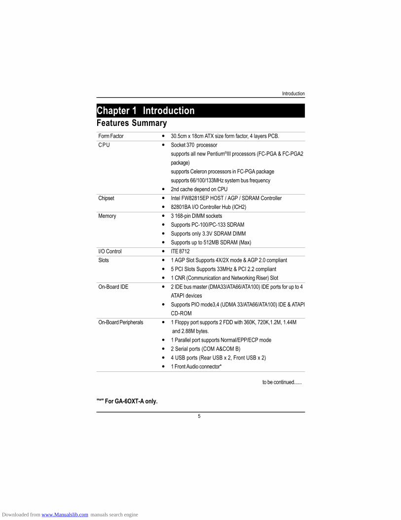
Form Factor 30.5cm x 18cm ATX size form factor, 4 layers PCB.CPU Socket 370 processor
supports all new Pentium®III processors (FC-PGA & FC-PGA2package)supports Celeron processors in FC-PGA packagesupports 66/100/133MHz system bus frequency2nd cache depend on CPU
Chipset Intel FW82815EP HOST / AGP / SDRAM Controller82801BA I/O Controller Hub (ICH2)
Memory 3 168-pin DIMM socketsSupports PC-100/PC-133 SDRAMSupports only 3.3V SDRAM DIMMSupports up to 512MB SDRAM (Max)
I/O Control ITE 8712Slots 1 AGP Slot Supports 4X/2X mode & AGP 2.0 compliant
5 PCI Slots Supports 33MHz & PCI 2.2 compliant1 CNR (Communication and Networking Riser) Slot
On-Board IDE 2 IDE bus master (DMA33/ATA66/ATA100) IDE ports for up to 4ATAPI devicesSupports PIO mode3,4 (UDMA 33/ATA66/ATA100) IDE & ATAPICD-ROM
On-Board Peripherals 1 Floppy port supports 2 FDD with 360K, 720K,1.2M, 1.44M and 2.88M bytes.1 Parallel port supports Normal/EPP/ECP mode2 Serial ports (COM A&COM B)4 USB ports (Rear USB x 2, Front USB x 2)1 Front Audio connector*
Chapter 1 Introduction
to be continued......
Features Summary
"*" For GA-6OXT-A only.
Downloaded from www.Manualslib.com manuals search engine
6
GA-6OXT(-A) Motherboard
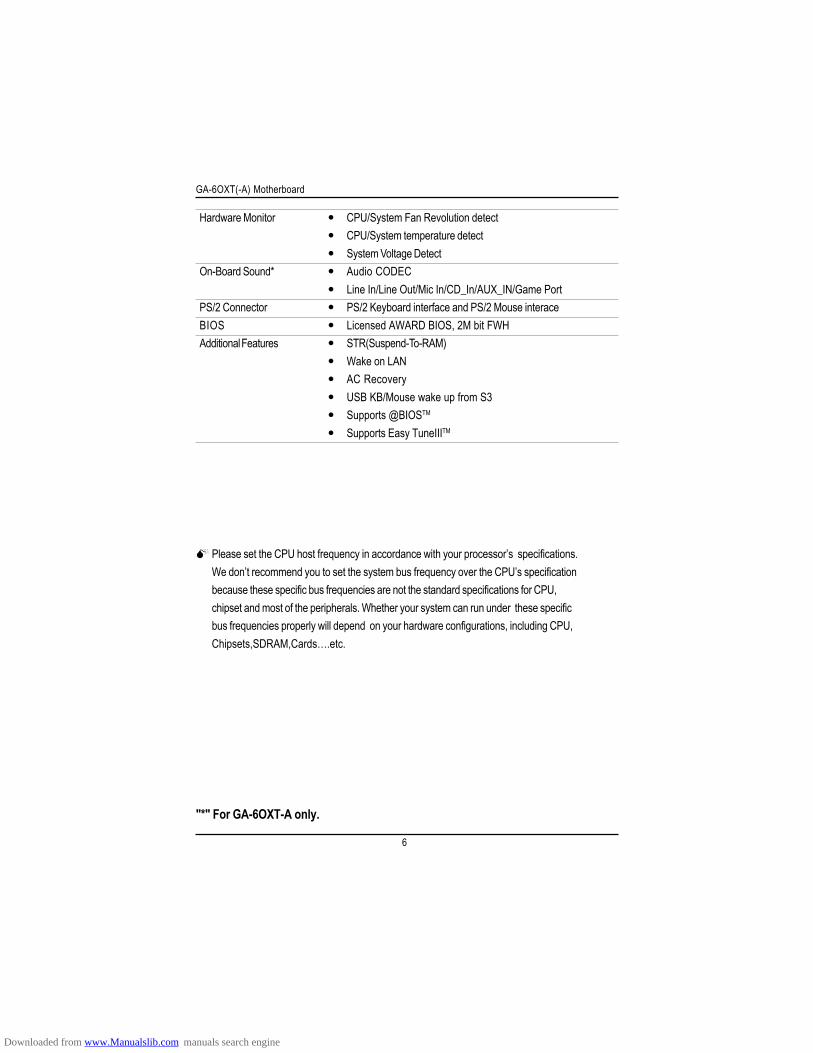
Please set the CPU host frequency in accordance with your processor’s specifications.We don’t recommend you to set the system bus frequency over the CPU’s specificationbecause these specific bus frequencies are not the standard specifications for CPU,chipset and most of the peripherals. Whether your system can run under these specificbus frequencies properly will depend on your hardware configurations, including CPU,Chipsets,SDRAM,Cards….etc.
Hardware Monitor CPU/System Fan Revolution detectCPU/System temperature detectSystem Voltage Detect
On-Board Sound* Audio CODECLine In/Line Out/Mic In/CD_In/AUX_IN/Game Port
PS/2 Connector PS/2 Keyboard interface and PS/2 Mouse interaceBIOS Licensed AWARD BIOS, 2M bit FWHAdditional Features STR(Suspend-To-RAM)
Wake on LANAC RecoveryUSB KB/Mouse wake up from S3Supports @BIOSTM
Supports Easy TuneIIITM
"*" For GA-6OXT-A only.
Downloaded from www.Manualslib.com manuals search engine
7
Introduction
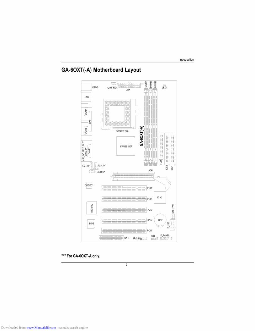
"*" For GA-6OXT-A only.
GA-6OXT(-A) Motherboard Layout
KB/MS CPU_FANATX
LED1
SOCKET 370
FW82815EP
USB
COMA
COMB
LPT
GA-6O
XT(-A
)
ICH2PCI2
PCI3
PCI4
PCI5
BAT1
SYS_
FAN
F_US
B
F_PANELWOLCNR
BIOS
ITE
8712
IR/CIR
IDE1
IDE2
FDD
DIMM
1
DIMM
2
DIMM
3
AGP
PCI1CODEC*
AUX_IN*CD_IN*
F_AUDIO*
GAME
*LI
NE_I
N*LI
NE_O
UT*
MIC
_IN*
Downloaded from www.Manualslib.com manuals search engine
8
GA-6OXT(-A) Motherboard
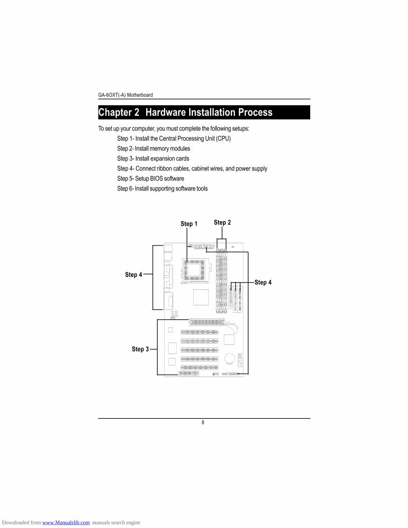
To set up your computer, you must complete the following setups:Step 1- Install the Central Processing Unit (CPU)Step 2- Install memory modulesStep 3- Install expansion cardsStep 4- Connect ribbon cables, cabinet wires, and power supplyStep 5- Setup BIOS softwareStep 6- Install supporting software tools
Chapter 2 Hardware Installation Process
Step 4
Step 2Step 1
Step 4
Step 3
Downloaded from www.Manualslib.com manuals search engine
9
Hardware Installation Process
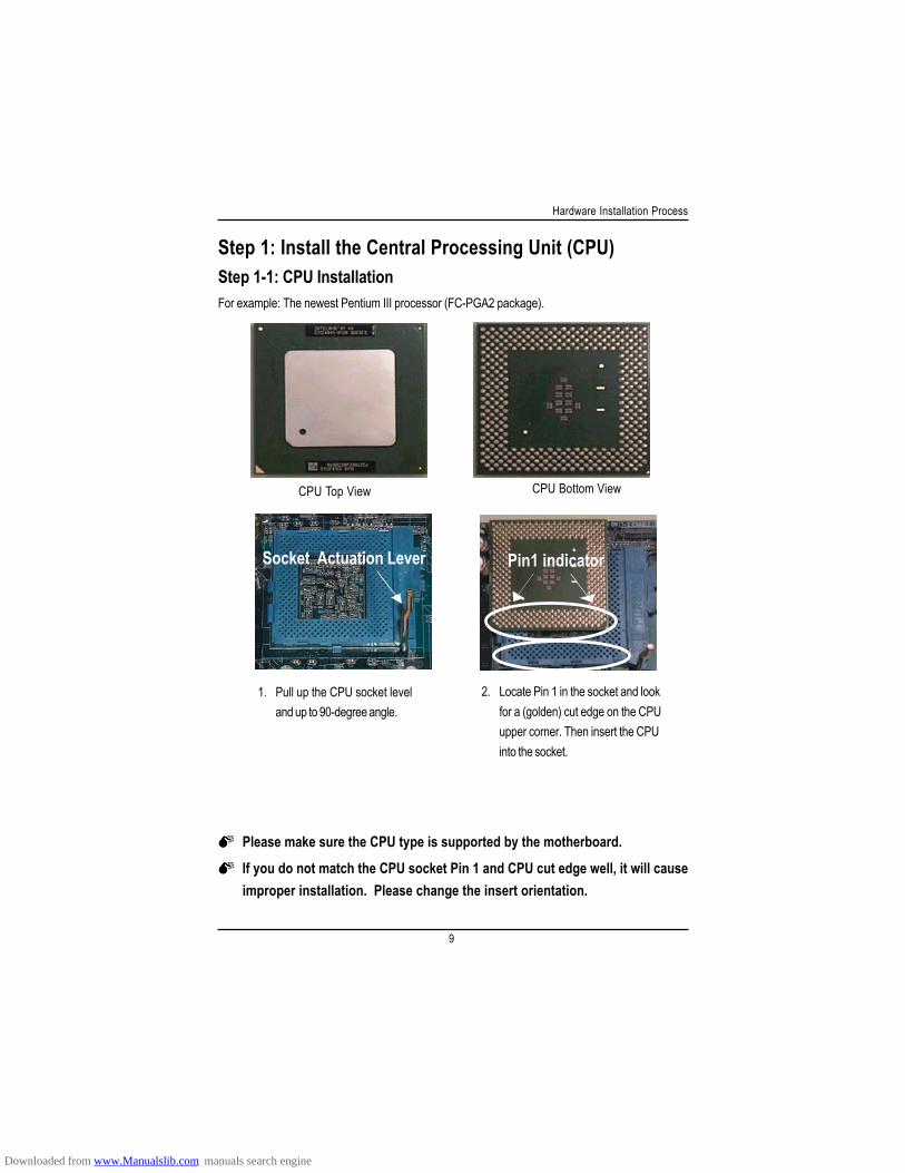
Step 1-1: CPU Installation
If you do not match the CPU socket Pin 1 and CPU cut edge well, it will cause improper installation. Please change the insert orientation.
CPU Top View CPU Bottom View
1. Pull up the CPU socket leveland up to 90-degree angle.
2. Locate Pin 1 in the socket and lookfor a (golden) cut edge on the CPUupper corner. Then insert the CPUinto the socket.
For example: The newest Pentium III processor (FC-PGA2 package).
Step 1: Install the Central Processing Unit (CPU)
Socket Actuation Lever Pin1 indicator
Please make sure the CPU type is supported by the motherboard.
Downloaded from www.Manualslib.com manuals search engine
1 0
GA-6OXT(-A) Motherboard
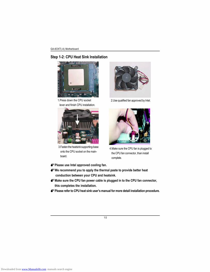
Step 1-2: CPU Heat Sink Installation
1.Press down the CPU socket lever and finish CPU installation.
Please use Intel approved cooling fan.We recommend you to apply the thermal paste to provide better heatconduction between your CPU and heatsink.Make sure the CPU fan power cable is plugged in to the CPU fan connector,this completes the installation.Please refer to CPU heat sink user’s manual for more detail installation procedure.
3.Fasten the heatsink supporting-baseonto the CPU socket on the main-board.
2.Use qualified fan approved by Intel.
4.Make sure the CPU fan is plugged tothe CPU fan connector, than installcomplete.
Downloaded from www.Manualslib.com manuals search engine
1 1
Hardware Installation Process
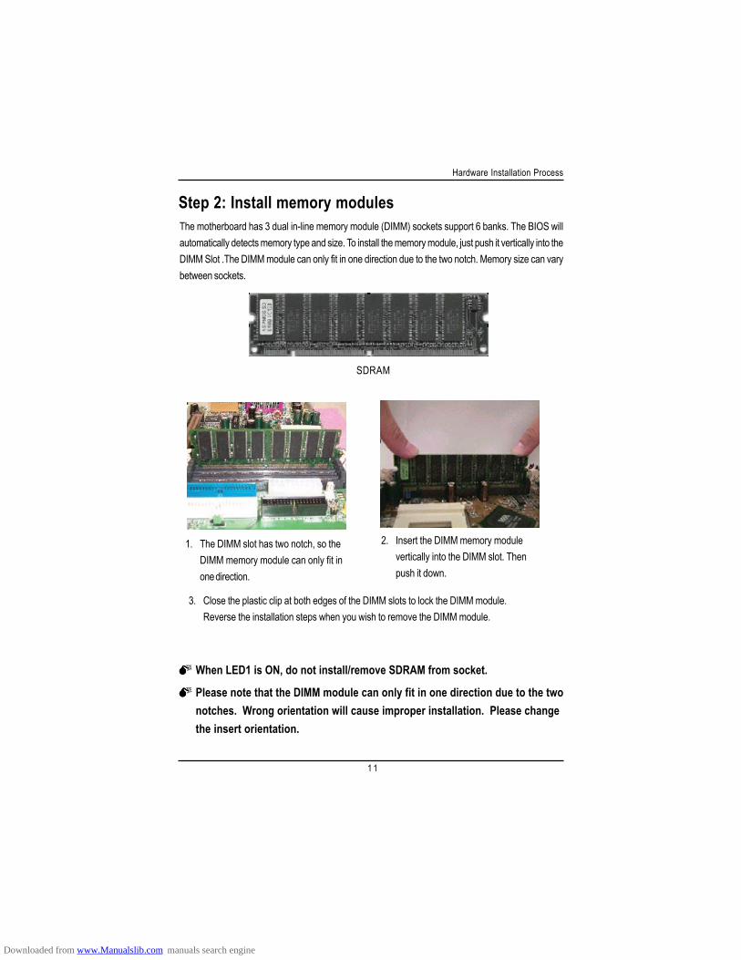
Step 2: Install memory modulesThe motherboard has 3 dual in-line memory module (DIMM) sockets support 6 banks. The BIOS willautomatically detects memory type and size. To install the memory module, just push it vertically into theDIMM Slot .The DIMM module can only fit in one direction due to the two notch. Memory size can varybetween sockets.
1. The DIMM slot has two notch, so theDIMM memory module can only fit inone direction.
2. Insert the DIMM memory modulevertically into the DIMM slot. Thenpush it down.
3. Close the plastic clip at both edges of the DIMM slots to lock the DIMM module.Reverse the installation steps when you wish to remove the DIMM module.
SDRAM
When LED1 is ON, do not install/remove SDRAM from socket.
Please note that the DIMM module can only fit in one direction due to the twonotches. Wrong orientation will cause improper installation. Please changethe insert orientation.
Downloaded from www.Manualslib.com manuals search engine
1 2
GA-6OXT(-A) Motherboard
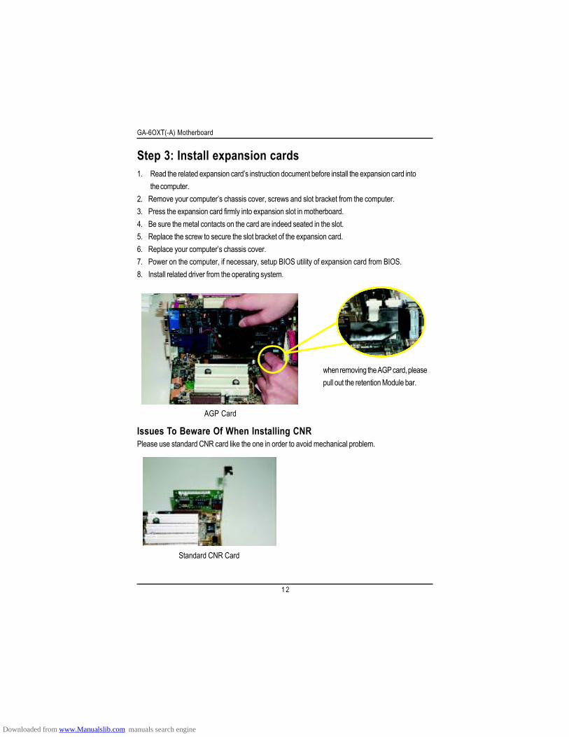
Step 3: Install expansion cards1. Read the related expansion card’s instruction document before install the expansion card into
the computer.2. Remove your computer’s chassis cover, screws and slot bracket from the computer.3. Press the expansion card firmly into expansion slot in motherboard.4. Be sure the metal contacts on the card are indeed seated in the slot.5. Replace the screw to secure the slot bracket of the expansion card.6. Replace your computer’s chassis cover.7. Power on the computer, if necessary, setup BIOS utility of expansion card from BIOS.8. Install related driver from the operating system.
AGP Card
when removing the AGP card, pleasepull out the retention Module bar.
Issues To Beware Of When Installing CNRPlease use standard CNR card like the one in order to avoid mechanical problem.
Standard CNR Card
Downloaded from www.Manualslib.com manuals search engine
1 3
Hardware Installation Process
Step 4: Connect ribbon cables, cabinet wires, and powersupply
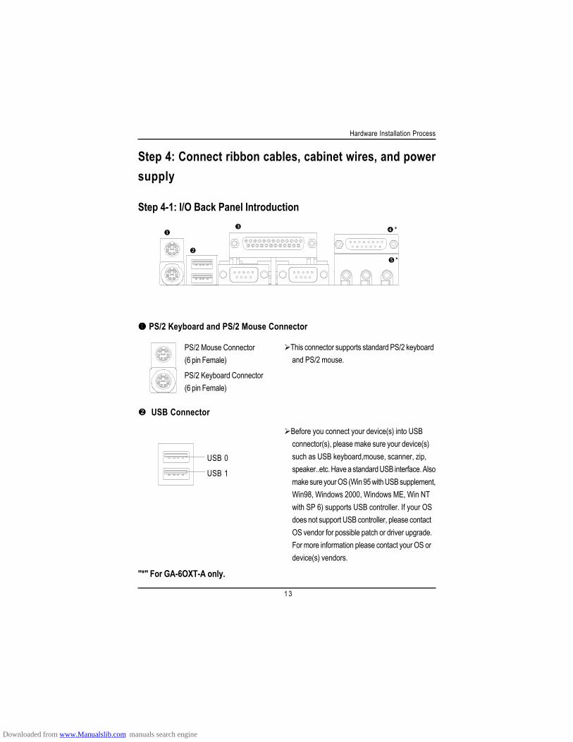
Step 4-1: I/O Back Panel Introduction
PS/2 Keyboard and PS/2 Mouse Connector
This connector supports standard PS/2 keyboardand PS/2 mouse.
USB Connector
Before you connect your device(s) into USBconnector(s), please make sure your device(s)such as USB keyboard,mouse, scanner, zip,speaker..etc. Have a standard USB interface. Alsomake sure your OS (Win 95 with USB supplement,Win98, Windows 2000, Windows ME, Win NTwith SP 6) supports USB controller. If your OSdoes not support USB controller, please contactOS vendor for possible patch or driver upgrade.For more information please contact your OS ordevice(s) vendors.
PS/2 Mouse Connector(6 pin Female)
PS/2 Keyboard Connector(6 pin Female)
USB 0
USB 1
*
*
"*" For GA-6OXT-A only.
Downloaded from www.Manualslib.com manuals search engine
1 4
GA-6OXT(-A) Motherboard
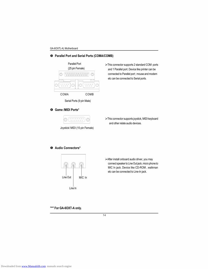
Parallel Port and Serial Ports (COMA/COMB)
Parallel Port(25 pin Female)
Serial Ports (9 pin Male)
COMA COMB
This connector supports 2 standard COM portsand 1 Parallel port. Device like printer can beconnected to Parallel port ; mouse and modemetc can be connected to Serial ports.
Game /MIDI Ports*
Joystick/ MIDI (15 pin Female)
This connector supports joystick, MIDI keyboardand other relate audio devices.
Audio Connectors*
Line Out
Line In
MIC In
After install onboard audio driver, you mayconnect speaker to Line Out jack, micro phone toMIC In jack. Device like CD-ROM , walkmanetc can be connected to Line-In jack.
"*" For GA-6OXT-A only.
Downloaded from www.Manualslib.com manuals search engine
1 5
Hardware Installation Process
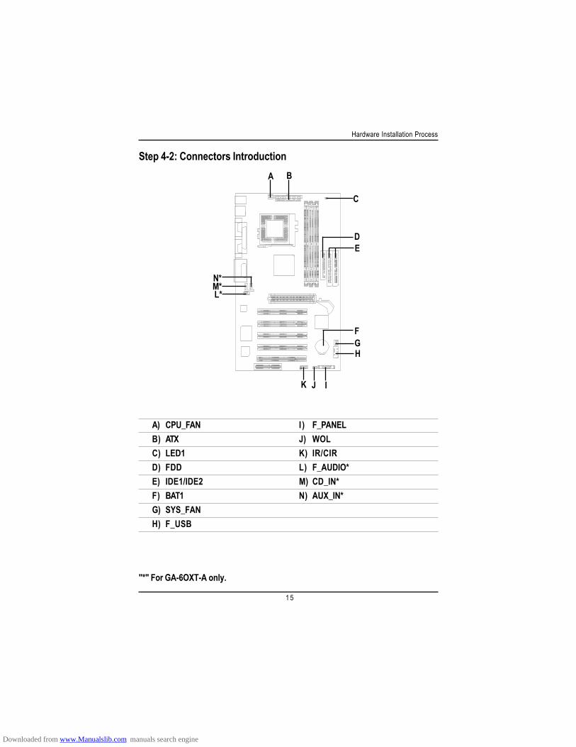
"*" For GA-6OXT-A only.
Step 4-2: Connectors Introduction
A) CPU_FAN I) F_PANELB) ATX J) WOLC) LED1 K) IR/CIRD) FDD L) F_AUDIO*E) IDE1/IDE2 M) CD_IN*F) BAT1 N) AUX_IN*G) SYS_FANH) F_USB
A B
C
DE
F
J
GH
IK
L*M*N*
Downloaded from www.Manualslib.com manuals search engine
1 6
GA-6OXT(-A) Motherboard
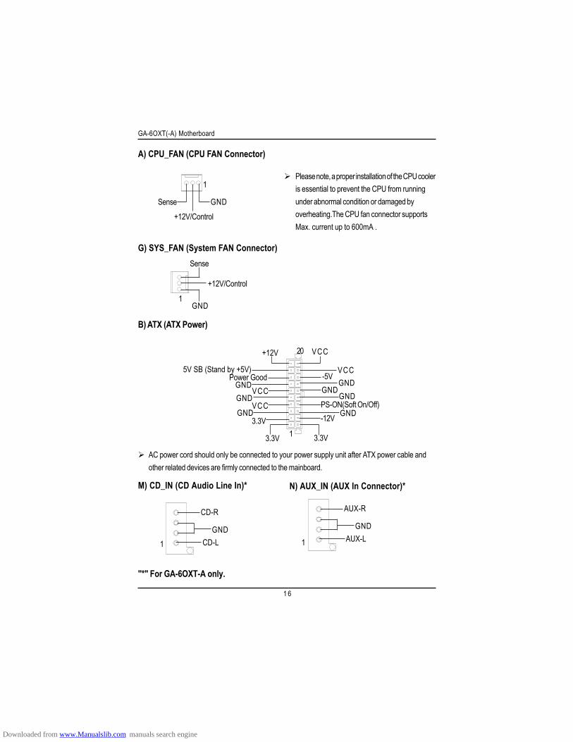
"*" For GA-6OXT-A only.
A) CPU_FAN (CPU FAN Connector)
G) SYS_FAN (System FAN Connector)
B) ATX (ATX Power)
PS-ON(Soft On/Off)
3.3V
3.3VGND
GNDGND
VCC
VCC
+12V
5V SB (Stand by +5V)Power Good
3.3V
GND
GNDGND
GND
VCC
VCC
-12V
1
20
-5V
Please note, a proper installation of the CPU cooleris essential to prevent the CPU from runningunder abnormal condition or damaged byoverheating.The CPU fan connector supportsMax. current up to 600mA .
AC power cord should only be connected to your power supply unit after ATX power cable andother related devices are firmly connected to the mainboard.
+12V/Control
Sense GND
1
+12V/Control
Sense
GND1
M) CD_IN (CD Audio Line In)*
1GND
CD-L
CD-R
N) AUX_IN (AUX In Connector)*
1
GNDAUX-L
AUX-R
Downloaded from www.Manualslib.com manuals search engine
1 7
Hardware Installation Process
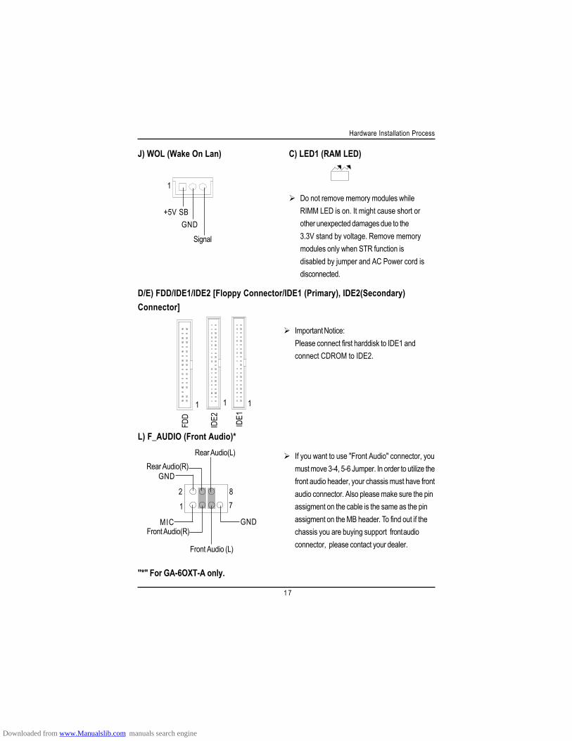
"*" For GA-6OXT-A only.
J) WOL (Wake On Lan)
+5V SBGND
Signal
1
1
D/E) FDD/IDE1/IDE2 [Floppy Connector/IDE1 (Primary), IDE2(Secondary)Connector]
IDE1
1
IDE2
1
C) LED1 (RAM LED)
Important Notice:Please connect first harddisk to IDE1 andconnect CDROM to IDE2.
Do not remove memory modules whileRIMM LED is on. It might cause short orother unexpected damages due to the3.3V stand by voltage. Remove memorymodules only when STR function isdisabled by jumper and AC Power cord isdisconnected.
FDD
L) F_AUDIO (Front Audio)*
If you want to use "Front Audio" connector, youmust move 3-4, 5-6 Jumper. In order to utilize thefront audio header, your chassis must have frontaudio connector. Also please make sure the pinassigment on the cable is the same as the pinassigment on the MB header. To find out if thechassis you are buying support front audioconnector, please contact your dealer.
278
MIC
GNDRear Audio(R)
GND
Rear Audio(L)
Front Audio(R)
Front Audio (L)
1
Downloaded from www.Manualslib.com manuals search engine
1 8
GA-6OXT(-A) Motherboard
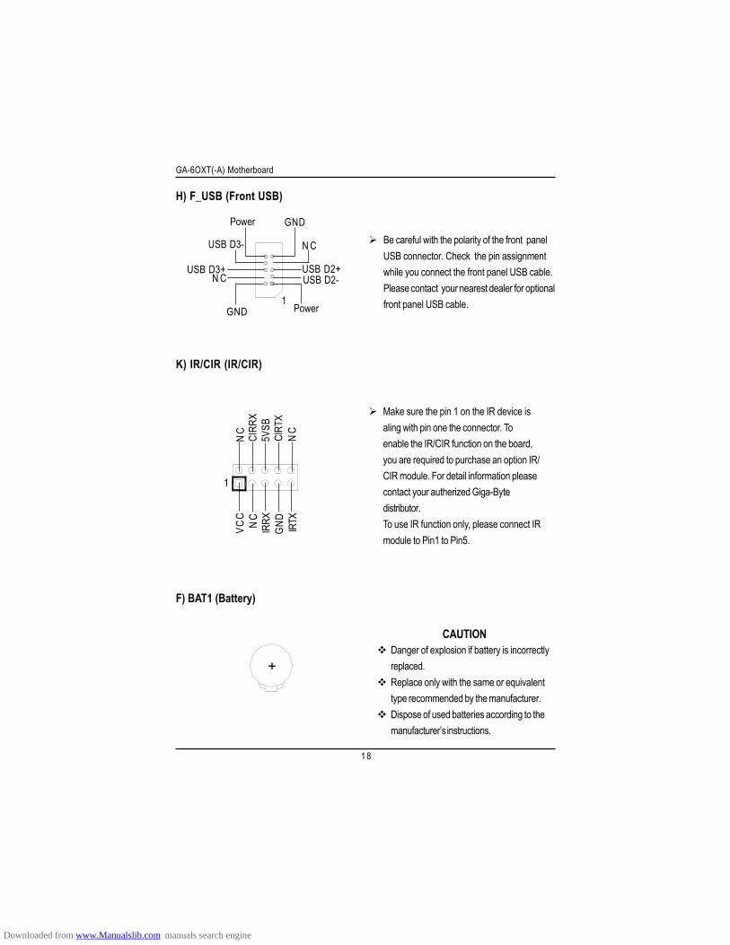
H) F_USB (Front USB)
Be careful with the polarity of the front panelUSB connector. Check the pin assignmentwhile you connect the front panel USB cable.Please contact your nearest dealer for optionalfront panel USB cable.
F) BAT1 (Battery)
CAUTIONDanger of explosion if battery is incorrectlyreplaced.Replace only with the same or equivalenttype recommended by the manufacturer.Dispose of used batteries according to themanufacturer’s instructions.
GND
N CUSB D3+
USB D3-
Power
Power
USB D2-USB D2+
N C
GND
1
+
K) IR/CIR (IR/CIR)
1
VCC
NC
IRRX
GND
IRTX
NC
CIRR
X5V
SBCI
RTX
NC
Make sure the pin 1 on the IR device isaling with pin one the connector. Toenable the IR/CIR function on the board,you are required to purchase an option IR/CIR module. For detail information pleasecontact your autherized Giga-Bytedistributor.To use IR function only, please connect IRmodule to Pin1 to Pin5.
Downloaded from www.Manualslib.com manuals search engine
1 9
Hardware Installation Process
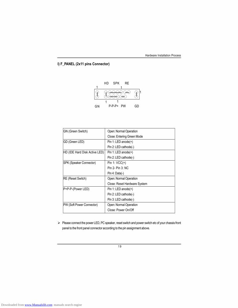
I) F_PANEL (2x11 pins Connector)
Please connect the power LED, PC speaker, reset switch and power switch etc of your chassis frontpanel to the front panel connector according to the pin assignment above.
GN (Green Switch) Open: Normal OperationClose: Entering Green Mode
GD (Green LED) Pin 1: LED anode(+)Pin 2: LED cathode(-)
HD (IDE Hard Disk Active LED) Pin 1: LED anode(+)Pin 2: LED cathode(-)
SPK (Speaker Connector) Pin 1: VCC(+)Pin 2- Pin 3: NCPin 4: Data(-)
RE (Reset Switch) Open: Normal OperationClose: Reset Hardware System
P+P-P-(Power LED) Pin 1: LED anode(+)Pin 2: LED cathode(-)Pin 3: LED cathode(-)
PW (Soft Power Connector) Open: Normal OperationClose: Power On/Off
1 11
11GN
HD SPK RE
GDP-P-P+ PW
Downloaded from www.Manualslib.com manuals search engine
GA-6OXT(-A) Motherboard
2 0
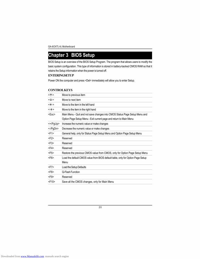
< > Move to previous item< > Move to next item< > Move to the item in the left hand< > Move to the item in the right hand<Esc> Main Menu - Quit and not save changes into CMOS Status Page Setup Menu and
Option Page Setup Menu - Exit current page and return to Main Menu<+/PgUp> Increase the numeric value or make changes<-/PgDn> Decrease the numeric value or make changes<F1> General help, only for Status Page Setup Menu and Option Page Setup Menu<F2> Reserved<F3> Reserved<F4> Reserved<F5> Restore the previous CMOS value from CMOS, only for Option Page Setup Menu<F6> Load the default CMOS value from BIOS default table, only for Option Page Setup
Menu<F7> Load the Setup Defaults<F8> Q-Flash Function<F9> Reserved<F10> Save all the CMOS changes, only for Main Menu
BIOS Setup is an overview of the BIOS Setup Program. The program that allows users to modify thebasic system configuration. This type of information is stored in battery-backed CMOS RAM so that itretains the Setup information when the power is turned off.ENTERING SETUPPower ON the computer and press <Del> immediately will allow you to enter Setup.
CONTROL KEYS
Chapter 3 BIOS Setup
Downloaded from www.Manualslib.com manuals search engine
BIOS Setup
2 1
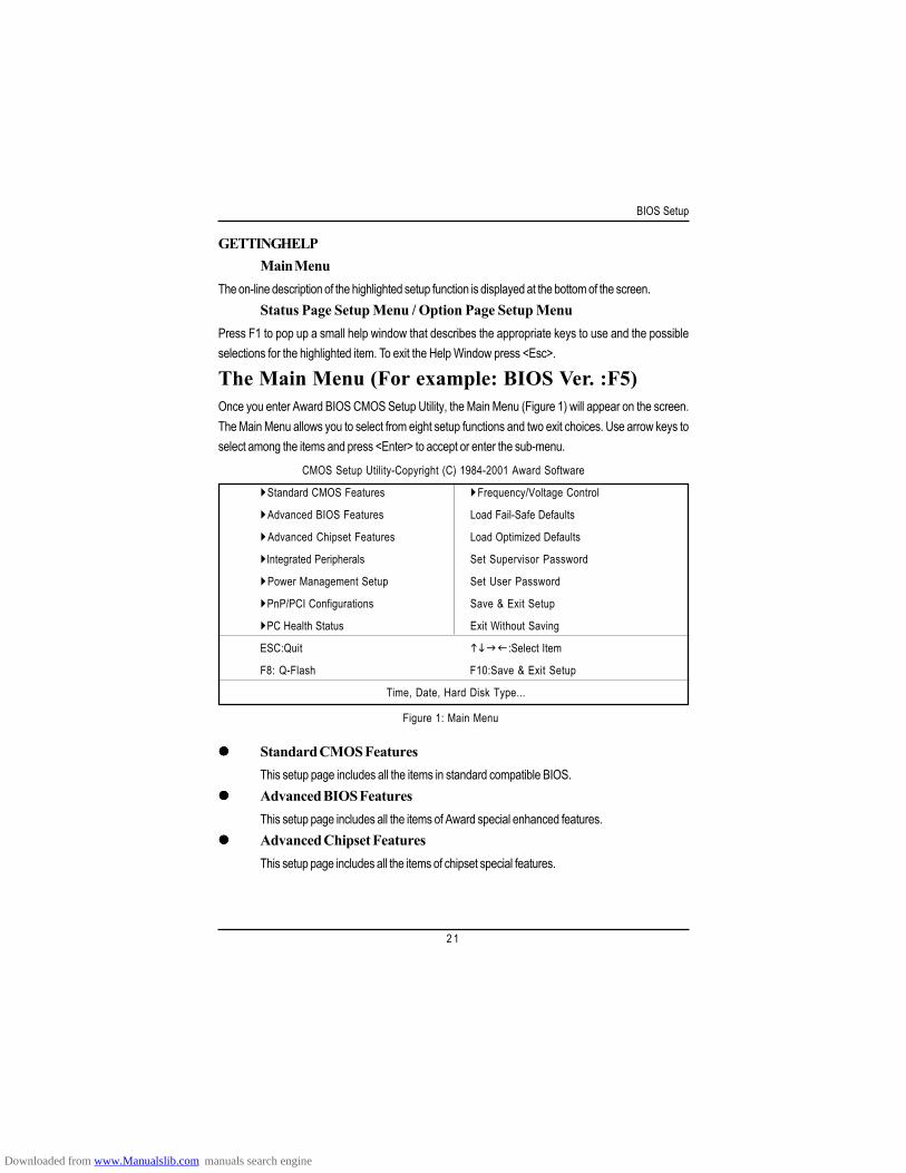
Standard CMOS FeaturesThis setup page includes all the items in standard compatible BIOS.Advanced BIOS FeaturesThis setup page includes all the items of Award special enhanced features.Advanced Chipset FeaturesThis setup page includes all the items of chipset special features.
GETTING HELPMain Menu
The on-line description of the highlighted setup function is displayed at the bottom of the screen.Status Page Setup Menu / Option Page Setup Menu
Press F1 to pop up a small help window that describes the appropriate keys to use and the possibleselections for the highlighted item. To exit the Help Window press <Esc>.
The Main Menu (For example: BIOS Ver. :F5)Once you enter Award BIOS CMOS Setup Utility, the Main Menu (Figure 1) will appear on the screen.The Main Menu allows you to select from eight setup functions and two exit choices. Use arrow keys toselect among the items and press <Enter> to accept or enter the sub-menu.
Figure 1: Main Menu
CMOS Setup Utility-Copyright (C) 1984-2001 Award Software
Standard CMOS Features Frequency/Voltage Control
Advanced BIOS Features Load Fail-Safe Defaults
Advanced Chipset Features Load Optimized Defaults
Integrated Peripherals Set Supervisor Password
Power Management Setup Set User Password
PnP/PCI Configurations Save & Exit Setup
PC Health Status Exit Without Saving
ESC:Quit :Select Item
F8: Q-Flash F10:Save & Exit Setup
Time, Date, Hard Disk Type...
Downloaded from www.Manualslib.com manuals search engine
GA-6OXT(-A) Motherboard
2 2
Integrated PeripheralsThis setup page includes all onboard peripherals.Power Management SetupThis setup page includes all the items of Green function features.PnP/PCI ConfigurationsThis setup page includes all the configurations of PCI & PnP ISA resources.PC Health StatusThis setup page is the System auto detect Temperature, voltage, fan, speed.Frequency/Voltage ControlThis setup page is control CPU’s clock and frequency ratio.Load Fail-Safe DefaultsFail-Safe Defaults indicates the value of the system parameters which the system wouldbe in safe configuration.Load Optimized DefaultsOptimized Defaults indicates the value of the system parameters which the system wouldbe in best performance configuration.Set Supervisor passwordChange, set, or disable password. It allows you to limit access to the system and Setup,or just to Setup.Set User passwordChange, set, or disable password. It allows you to limit access to the system.Save & Exit SetupSave CMOS value settings to CMOS and exit setup.Exit Without SavingAbandon all CMOS value changes and exit setup.
Downloaded from www.Manualslib.com manuals search engine
BIOS Setup
2 3
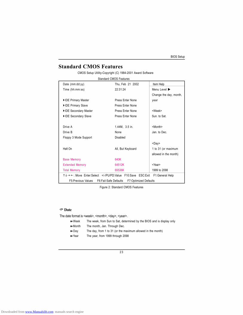
Standard CMOS Features
Figure 2: Standard CMOS Features
DateThe date format is <week>, <month>, <day>, <year>.
Week The week, from Sun to Sat, determined by the BIOS and is display onlyMonth The month, Jan. Through Dec.Day The day, from 1 to 31 (or the maximum allowed in the month)Year The year, from 1999 through 2098
CMOS Setup Utility-Copyright (C) 1984-2001 Award Software
Standard CMOS FeaturesDate (mm:dd:yy) Thu, Feb 21 2002 Item HelpTime (hh:mm:ss) 22:31:24 Menu Level
Change the day, month,IDE Primary Master Press Enter None yearIDE Primary Slave Press Enter NoneIDE Secondary Master Press Enter None <Week>IDE Secondary Slave Press Enter None Sun. to Sat.
Drive A 1.44M, 3.5 in. <Month>Drive B None Jan. to Dec.Floppy 3 Mode Support Disabled
<Day>Halt On All, But Keyboard 1 to 31 (or maximum
allowed in the month)Base Memory 640KExtended Memory 64512K <Year>Total Memory 65536K 1999 to 2098
: Move Enter:Select +/-/PU/PD:Value F10:Save ESC:Exit F1:General Help F5:Previous Values F6:Fail-Safe Defaults F7:Optimized Defaults
Downloaded from www.Manualslib.com manuals search engine
GA-6OXT(-A) Motherboard
2 4
TimeThe times format in <hour> <minute> <second>. The time is calculated base on the 24-hour
military-time clock. For example, 1 p.m. is 13:00:00.
IDE Primary Master, Slave / Secondary Master, SlaveThe category identifies the types of hard disk from drive C to F that has been installed in the
computer. There are two types: auto type, and manual type. Manual type is user-definable; Auto typewhich will automatically detect HDD type.Note that the specifications of your drive must match with the drive table. The hard disk will not workproperly if you enter improper information for this category.If you select User Type, related information will be asked to enter to the following items. Enter theinformation directly from the keyboard and press <Enter>. Such information should be provided in thedocumentation form your hard disk vendor or the system manufacturer.
CYLS. Number of cylinders
HEADS Number of heads
PRECOMP Write precomp
LANDZONE Landing zone
SECTORSNumber of sectors
If a hard disk has not been installed select NONE and press <Enter>.
Drive A / Drive BThe category identifies the types of floppy disk drive A or drive B that has been installed in the
computer.None No floppy drive installed
360K, 5.25 in. 5.25 inch PC-type standard drive; 360K byte capacity.
1.2M, 5.25 in. 5.25 inch AT-type high-density drive; 1.2M byte capacity
(3.5 inch when 3 Mode is Enabled).
720K, 3.5 in. 3.5 inch double-sided drive; 720K byte capacity
1.44M, 3.5 in. 3.5 inch double-sided drive; 1.44M byte capacity.
2.88M, 3.5 in. 3.5 inch double-sided drive; 2.88M byte capacity.
Downloaded from www.Manualslib.com manuals search engine
BIOS Setup
2 5
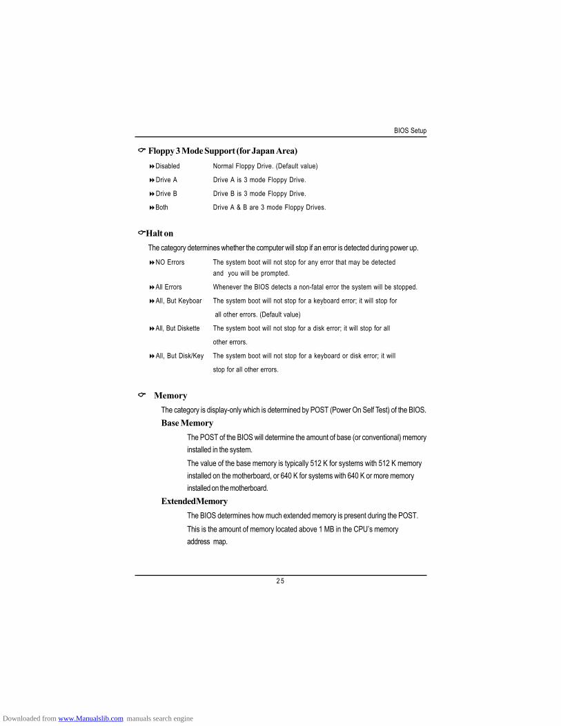
Floppy 3 Mode Support (for Japan Area)Disabled Normal Floppy Drive. (Default value)
Drive A Drive A is 3 mode Floppy Drive.
Drive B Drive B is 3 mode Floppy Drive.
Both Drive A & B are 3 mode Floppy Drives.
Halt onThe category determines whether the computer will stop if an error is detected during power up.
NO Errors The system boot will not stop for any error that may be detectedand you will be prompted.
All Errors Whenever the BIOS detects a non-fatal error the system will be stopped.
All, But Keyboar The system boot will not stop for a keyboard error; it will stop for
all other errors. (Default value)
All, But Diskette The system boot will not stop for a disk error; it will stop for all
other errors.
All, But Disk/Key The system boot will not stop for a keyboard or disk error; it will
stop for all other errors.
MemoryThe category is display-only which is determined by POST (Power On Self Test) of the BIOS.Base Memory
The POST of the BIOS will determine the amount of base (or conventional) memoryinstalled in the system.The value of the base memory is typically 512 K for systems with 512 K memoryinstalled on the motherboard, or 640 K for systems with 640 K or more memoryinstalled on the motherboard.
Extended MemoryThe BIOS determines how much extended memory is present during the POST.This is the amount of memory located above 1 MB in the CPU’s memoryaddress map.
Downloaded from www.Manualslib.com manuals search engine
GA-6OXT(-A) Motherboard
2 6
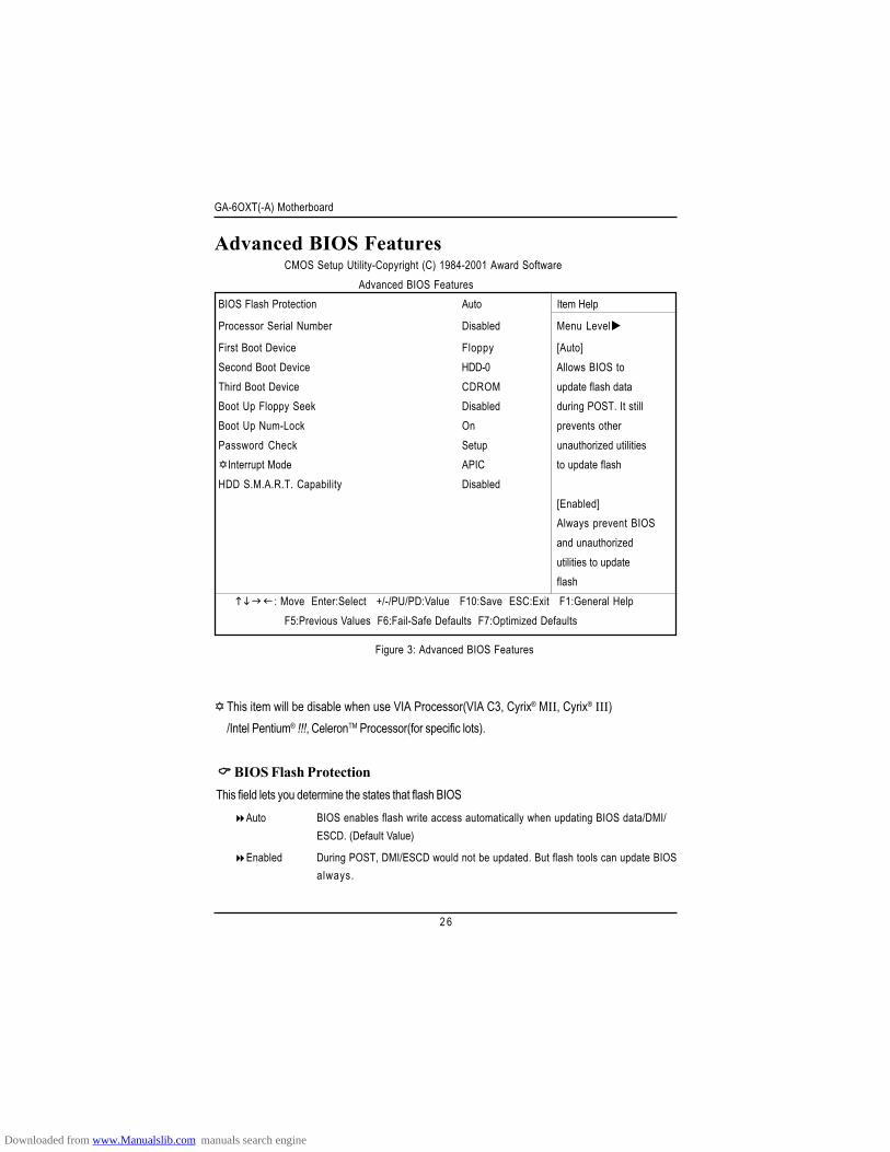
Advanced BIOS Features
BIOS Flash Protection This field lets you determine the states that flash BIOS
Auto BIOS enables flash write access automatically when updating BIOS data/DMI/ESCD. (Default Value)
Enabled During POST, DMI/ESCD would not be updated. But flash tools can update BIOSalways.
Figure 3: Advanced BIOS Features
This item will be disable when use VIA Processor(VIA C3, Cyrix® MII, Cyrix® III)/Intel Pentium® !!!, CeleronTM Processor(for specific lots).
CMOS Setup Utility-Copyright (C) 1984-2001 Award SoftwareAdvanced BIOS Features
BIOS Flash Protection Auto Item Help
Processor Serial Number Disabled Menu Level
First Boot Device Floppy [Auto]Second Boot Device HDD-0 Allows BIOS toThird Boot Device CDROM update flash dataBoot Up Floppy Seek Disabled during POST. It stillBoot Up Num-Lock On prevents otherPassword Check Setup unauthorized utilities
Interrupt Mode APIC to update flashHDD S.M.A.R.T. Capability Disabled
[Enabled]Always prevent BIOSand unauthorizedutilities to updateflash
: Move Enter:Select +/-/PU/PD:Value F10:Save ESC:Exit F1:General HelpF5:Previous Values F6:Fail-Safe Defaults F7:Optimized Defaults
Downloaded from www.Manualslib.com manuals search engine
BIOS Setup
2 7
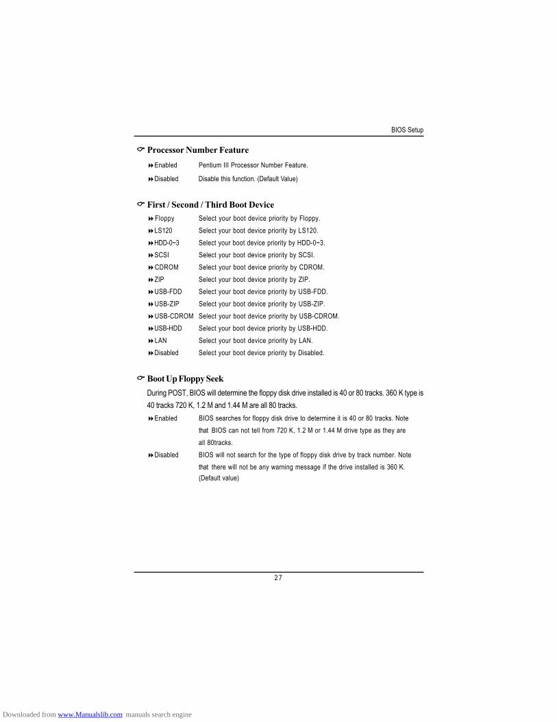
Processor Number FeatureEnabled Pentium III Processor Number Feature.
Disabled Disable this function. (Default Value)
First / Second / Third Boot DeviceFloppy Select your boot device priority by Floppy.LS120 Select your boot device priority by LS120.HDD-0~3 Select your boot device priority by HDD-0~3.SCSI Select your boot device priority by SCSI.CDROM Select your boot device priority by CDROM.ZIP Select your boot device priority by ZIP.USB-FDD Select your boot device priority by USB-FDD.USB-ZIP Select your boot device priority by USB-ZIP.USB-CDROM Select your boot device priority by USB-CDROM.USB-HDD Select your boot device priority by USB-HDD.LAN Select your boot device priority by LAN.Disabled Select your boot device priority by Disabled.
Boot Up Floppy SeekDuring POST, BIOS will determine the floppy disk drive installed is 40 or 80 tracks. 360 K type is40 tracks 720 K, 1.2 M and 1.44 M are all 80 tracks.
Enabled BIOS searches for floppy disk drive to determine it is 40 or 80 tracks. Notethat BIOS can not tell from 720 K, 1.2 M or 1.44 M drive type as they areall 80tracks.
Disabled BIOS will not search for the type of floppy disk drive by track number. Notethat there will not be any warning message if the drive installed is 360 K.(Default value)
Downloaded from www.Manualslib.com manuals search engine
GA-6OXT(-A) Motherboard
2 8
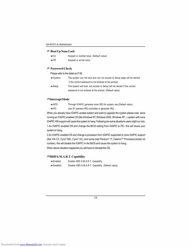
Boot Up Num-LockOn Keypad is number keys. (Default value)Off Keypad is arrow keys.
Password CheckPlease refer to the detail on P.56
System The system can not boot and can not access to Setup page will be denied if the correct password is not entered at the prompt.
Setup The system will boot, but access to Setup will be denied if the correctpassword is not entered at the prompt. (Default value)
Interrupt ModeAPIC Through IOAPIC generate more IRQ for system use.(Default value)PIC Use AT stantard IRQ controlles to generate IRQ.
When you already have IOAPIC enable system and want to upgrade the system please note, sincerunning an IOAPIC enabled OS (like Windows NT,Windows 2000, Windows XP...) system with noneIOAPIC HW support will cause the system to hang. Following are some situations users might run into:1.An IOAPIC enabled OS and change the BIOS setting from IOAPIC to PIC, this will cause yoursystem to hang.2.An IOAPIC enabled OS and change a processor from IOAPIC supported to none IOAPIC support(like VIA C3, Cyrix® MII, Cyrix® III), and some Intel Pentium® !!!, CeleronTM Processor(certain lotnumber), this will disable the IOAPIC in the BIOS and cause the system to hang.When above situation happened you will have to reinstall the OS.
HDD S.M.A.R.T. CapabilityEnabled Enable HDD S.M.A.R.T. Capability.Disabled Disable HDD S.M.A.R.T. Capability. (Default value)
Downloaded from www.Manualslib.com manuals search engine
BIOS Setup
2 9
Advanced Chipset Features
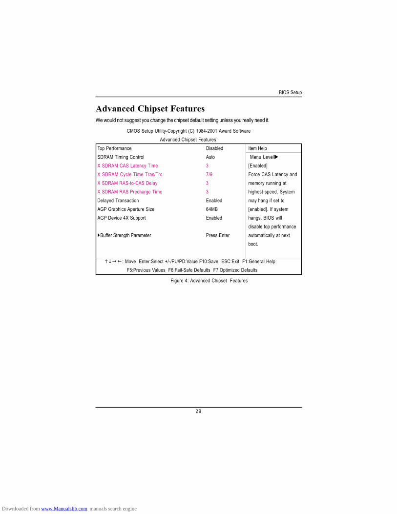
Figure 4: Advanced Chipset Features
We would not suggest you change the chipset default setting unless you really need it.
CMOS Setup Utility-Copyright (C) 1984-2001 Award SoftwareAdvanced Chipset Features
Top Performance Disabled Item HelpSDRAM Timing Control Auto Menu LevelX SDRAM CAS Latency Time 3 [Enabled]X SDRAM Cycle Time Tras/Trc 7/9 Force CAS Latency andX SDRAM RAS-to-CAS Delay 3 memory running atX SDRAM RAS Precharge Time 3 highest speed. SystemDelayed Transaction Enabled may hang if set toAGP Graphics Aperture Size 64MB [enabled]. If systemAGP Device 4X Support Enabled hangs, BIOS will
disable top performanceBuffer Strength Parameter Press Enter automatically at next
boot.
: Move Enter:Select +/-/PU/PD:Value F10:Save ESC:Exit F1:General HelpF5:Previous Values F6:Fail-Safe Defaults F7:Optimized Defaults
Downloaded from www.Manualslib.com manuals search engine
GA-6OXT(-A) Motherboard
3 0
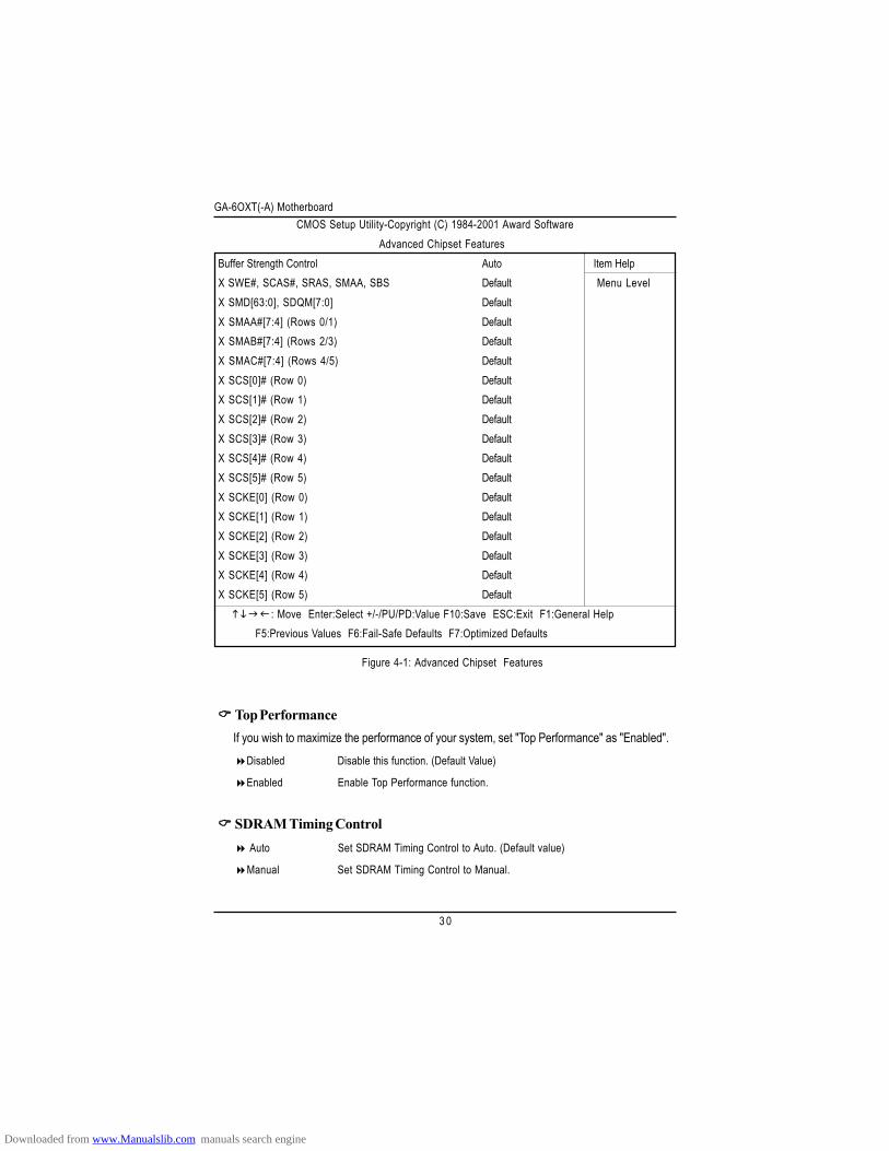
Figure 4-1: Advanced Chipset Features
Top Performance If you wish to maximize the performance of your system, set "Top Performance" as "Enabled".
Disabled Disable this function. (Default Value)
Enabled Enable Top Performance function.
SDRAM Timing Control Auto Set SDRAM Timing Control to Auto. (Default value)
Manual Set SDRAM Timing Control to Manual.
CMOS Setup Utility-Copyright (C) 1984-2001 Award SoftwareAdvanced Chipset Features
Buffer Strength Control Auto Item HelpX SWE#, SCAS#, SRAS, SMAA, SBS Default Menu LevelX SMD[63:0], SDQM[7:0] DefaultX SMAA#[7:4] (Rows 0/1) DefaultX SMAB#[7:4] (Rows 2/3) DefaultX SMAC#[7:4] (Rows 4/5) DefaultX SCS[0]# (Row 0) DefaultX SCS[1]# (Row 1) DefaultX SCS[2]# (Row 2) DefaultX SCS[3]# (Row 3) DefaultX SCS[4]# (Row 4) DefaultX SCS[5]# (Row 5) DefaultX SCKE[0] (Row 0) DefaultX SCKE[1] (Row 1) DefaultX SCKE[2] (Row 2) DefaultX SCKE[3] (Row 3) DefaultX SCKE[4] (Row 4) DefaultX SCKE[5] (Row 5) Default
: Move Enter:Select +/-/PU/PD:Value F10:Save ESC:Exit F1:General HelpF5:Previous Values F6:Fail-Safe Defaults F7:Optimized Defaults
Downloaded from www.Manualslib.com manuals search engine
BIOS Setup
3 1
SDRAM CAS Latency Time3 Set SDRAM CAS Latency to 3 SCLKS.(Default Value)
2 Set SDRAM CAS Latency to 2 SCLKS.
SDRAM Cycle Time Tras/Trc7/9 Set SDRAM Tras/Trc Cycle time to 7/9 SCLKs. (Default value)
5/7 Set SDRAM Tras/Trc Cycle time to 5/7 SCLKs.
SDRAM RAS-to-CAS Delay3 Set SDRAM RAS-to-CAS delay 3 SCLKs. (Default value)
2 Set SDRAM RAS-to-CAS delay 2 SCLKs.
SDRAM RAS Precharge Time3 Set SDRAM RAS Precharge Time to 3. (Default value)
2 Set SDRAM RAS Precharge Time to 2.
Delayed TransactionDisabled Normal operation.
Enabled For slow speed ISA device in system. (Default value)
AGP Graphics Aperture Size32MB AGP Graphics Aperture Size is 32MB.
64MB AGP Graphics Aperture Size is 64MB. (Default Value)
AGP Device 4X SupportEnabled Enable support AGP Device 4X function. (Default Value)
Disabled Disable this function.
Downloaded from www.Manualslib.com manuals search engine
GA-6OXT(-A) Motherboard
3 2
Buffer Strength ControlAuto Set SDRAM Buffer Strength to Auto. (Default value)
Manual Set SDRAM Buffer Strength to Manual.
SWE#, SCAS#, SRAS#, SMAA, SBSDefault Set SWE#, SCAS#, SRAS#, SMAA, SBS to Default. (Default value)
1.7x Set SWE#, SCAS#, SRAS#, SMAA, SBS to 1.7x.
0.7x Set SWE#, SCAS#, SRAS#, SMAA, SBS to 0.7x.
1.0x Set SWE#, SCAS#, SRAS#, SMAA, SBS to 1.0x.
SMD[63:0], SDQM[7:0]Default Set SMD[63:0], SDQM[7:0] to Default. (Default value)
1.7x Set SMD[63:0], SDQM[7:0] to 1.7x.
0.7x Set SMD[63:0], SDQM[7:0] to 0.7x.
1.0x Set SMD[63:0], SDQM[7:0] to 1.0x.
SMAA#[7:4] (Rows 0/1)Default Set SMAA#[7:4] (Rows 0/1) to Default. (Default value)
2.7x Set SMAA#[7:4] (Rows 0/1) to 2.7x.
1.7x Set SMAA#[7:4] (Rows 0/1) to 1.7x.
1.0x Set SMAA#[7:4] (Rows 0/1) to 1.0x.
SMAB#[7:4] (Rows 2/3)Default Set SMAB#[7:4] (Rows 2/3) to Default. (Default value)
2.7x Set SMAB#[7:4] (Rows 2/3) to 2.7x.
1.7x Set SMAB#[7:4] (Rows 2/3) to 1.7x.
1.0x Set SMAB#[7:4] (Rows 2/3) to 1.0x.
Downloaded from www.Manualslib.com manuals search engine
BIOS Setup
3 3
SMAC#[7:4] (Rows 4/5)Default Set SMAC#[7:4] (Rows 4/5) to Default. (Default value)
2.7x Set SMAC#[7:4] (Rows 4/5) to 2.7x.
1.7x Set SMAC#[7:4] (Rows 4/5) to 1.7x.
1.0x Set SMAC#[7:4] (Rows 4/5) to 1.0x.
SCS[0]# (Row 0)Default Set SCS[0]# (Row 0) to Default. (Default value)
1.7x Set SCS[0]# (Row 0) to 1.7x.
1.0x Set SCS[0]# (Row 0) to 1.0x.
SCS[1]# (Row 1)Default Set SCS[1]# (Row 1) to Default. (Default value)
1.7x Set SCS[1]# (Row 1) to 1.7x.
1.0x Set SCS[1]# (Row 1) to 1.0x.
SCS[2]# (Row 2)Default Set SCS[2]# (Row 2) to Default. (Default value)
1.7x Set SCS[2]# (Row 2) to 1.7x.
1.0x Set SCS[2]# (Row 2) to 1.0x.
SCS[3]# (Row 3)Default Set SCS[3]# (Row 3) to Default. (Default value)
1.7x Set SCS[3]# (Row 3) to 1.7x.
1.0x Set SCS[3]# (Row 3) to 1.0x.
Downloaded from www.Manualslib.com manuals search engine
GA-6OXT(-A) Motherboard
3 4
SCS[4]# (Row 4)Default Set SCS[4]# (Row 4) to Default. (Default value)
1.7x Set SCS[4]# (Row 4) to 1.7x.
1.0x Set SCS[4]# (Row 4) to 1.0x.
SCS[5]# (Row 5)Default Set SCS[5]# (Row 5) to Default. (Default value)
1.7x Set SCS[5]# (Row 5) to 1.7x.
1.0x Set SCS[5]# (Row 5) to 1.0x.
SCKE[0]# (Row 0)Default Set SCKE[0]# (Row 0) to Default. (Default value)
2.7x Set SCKE[0]# (Row 0) to 2.7x.
1.7x Set SCKE[0]# (Row 0) to 1.7x.
SCKE[1] (Row 1)Default Set SCKE[1] (Row 1) to Default. (Default value)
2.7x Set SCKE[1] (Row 1) to 2.7x.
1.7x Set SCKE[1] (Row 1) to 1.7x.
SCKE[2] (Row 2)Default Set SCKE[2] (Row 2) to Default. (Default value)
2.7x Set SCKE[2] (Row 2) to 2.7x.
1.7x Set SCKE[2] (Row 2) to 1.7x.
SCKE[3] (Row 3)Default Set SCKE[3] (Row 3) to Default. (Default value)
2.7x Set SCKE[3] (Row 3) to 2.7x.
1.7x Set SCKE[3] (Row 3) to 1.7x.
Downloaded from www.Manualslib.com manuals search engine
BIOS Setup
3 5
SCKE[4] (Row 4)Default Set SCKE[4] (Row 4) to Default. (Default value)
2.7x Set SCKE[4] (Row 4) to 2.7x.
1.7x Set SCKE[4] (Row 4) to 1.7x.
SCKE[5] (Row 5)Default Set SCKE[5] (Row 5) to Default. (Default value)
2.7x Set SCKE[5] (Row 5) to 2.7x.
1.7x Set SCKE[5] (Row 5) to 1.7x.
Downloaded from www.Manualslib.com manuals search engine
GA-6OXT(-A) Motherboard
3 6
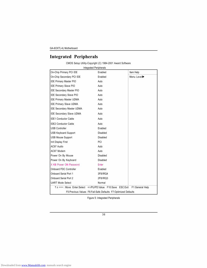
Integrated Peripherals
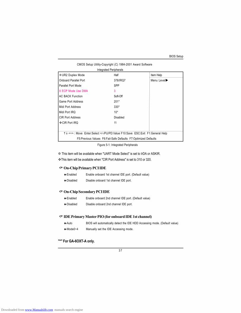
Figure 5: Integrated Peripherals
CMOS Setup Utility-Copyright (C) 1984-2001 Award SoftwareIntegrated Peripherals
On-Chip Primary PCI IDE Enabled Item HelpOn-Chip Secondary PCI IDE Enabled Menu LevelIDE Primary Master PIO AutoIDE Primary Slave PIO AutoIDE Secondary Master PIO AutoIDE Secondary Slave PIO AutoIDE Primary Master UDMA AutoIDE Primary Slave UDMA AutoIDE Secondary Master UDMA Auto
IDE Secondary Slave UDMA Auto
IDE1 Conductor Cable Auto
IDE2 Conductor Cable AutoUSB Controller EnabledUSB Keyboard Support DisabledUSB Mouse Support DisabledInit Display First PCIAC97 Audio AutoAC97 Modem AutoPower On By Mouse DisabledPower On By Keyboard DisabledX KB Power ON Password EnterOnboard FDC Controller EnabledOnboard Serial Port 1 3F8/IRQ4Onboard Serial Port 2 2F8/IRQ3UART Mode Select Normal
: Move Enter:Select +/-/PU/PD:Value F10:Save ESC:Exit F1:General HelpF5:Previous Values F6:Fail-Safe Defaults F7:Optimized Defaults
Downloaded from www.Manualslib.com manuals search engine
BIOS Setup
3 7
Figure 5-1: Integrated Peripherals
On-Chip Primary PCI IDEEnabled Enable onboard 1st channel IDE port. (Default value)
Disabled Disable onboard 1st channel IDE port.
On-Chip Secondary PCI IDEEnabled Enable onboard 2nd channel IDE port. (Default value)
Disabled Disable onboard 2nd channel IDE port.
IDE Primary Master PIO (for onboard IDE 1st channel)Auto BIOS will automatically detect the IDE HDD Accessing mode. (Default value)
Mode0~4 Manually set the IDE Accessing mode.
This item will be available when "UART Mode Select" is set to IrDA or ASKIR.This item will be available when "CIR Port Address" is set to 310 or 320.
CMOS Setup Utility-Copyright (C) 1984-2001 Award SoftwareIntegrated Peripherals
UR2 Duplex Mode Half Item HelpOnboard Parallel Port 378/IRQ7 Menu LevelParallel Port Mode SPPX ECP Mode Use DMA 3AC BACK Function Soft-OffGame Port Address 201*Midi Port Address 330*Midi Port IRQ 10*CIR Port Address Disabled
CIR Port IRQ 11
: Move Enter:Select +/-/PU/PD:Value F10:Save ESC:Exit F1:General HelpF5:Previous Values F6:Fail-Safe Defaults F7:Optimized Defaults
"*" For GA-6OXT-A only.
Downloaded from www.Manualslib.com manuals search engine
GA-6OXT(-A) Motherboard
3 8
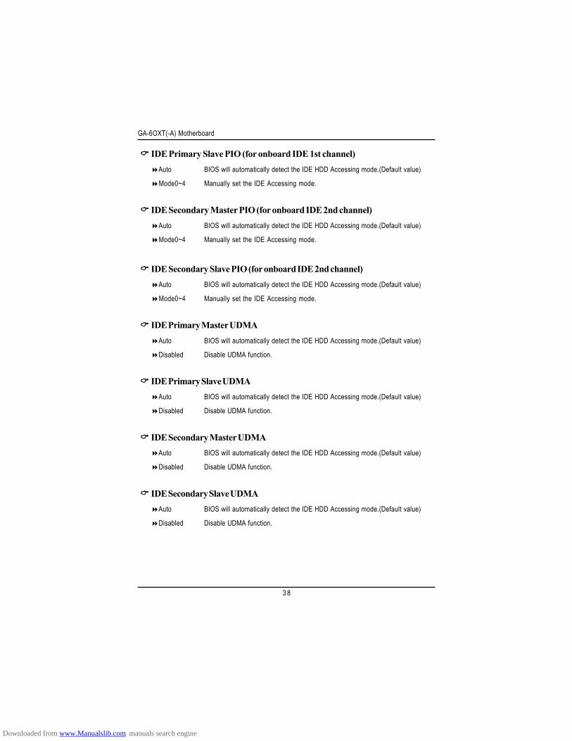
IDE Primary Slave PIO (for onboard IDE 1st channel)Auto BIOS will automatically detect the IDE HDD Accessing mode.(Default value)
Mode0~4 Manually set the IDE Accessing mode.
IDE Secondary Master PIO (for onboard IDE 2nd channel)Auto BIOS will automatically detect the IDE HDD Accessing mode.(Default value)
Mode0~4 Manually set the IDE Accessing mode.
IDE Secondary Slave PIO (for onboard IDE 2nd channel)Auto BIOS will automatically detect the IDE HDD Accessing mode.(Default value)
Mode0~4 Manually set the IDE Accessing mode.
IDE Primary Master UDMAAuto BIOS will automatically detect the IDE HDD Accessing mode.(Default value)
Disabled Disable UDMA function.
IDE Primary Slave UDMAAuto BIOS will automatically detect the IDE HDD Accessing mode.(Default value)
Disabled Disable UDMA function.
IDE Secondary Master UDMAAuto BIOS will automatically detect the IDE HDD Accessing mode.(Default value)
Disabled Disable UDMA function.
IDE Secondary Slave UDMAAuto BIOS will automatically detect the IDE HDD Accessing mode.(Default value)
Disabled Disable UDMA function.
Downloaded from www.Manualslib.com manuals search engine
BIOS Setup
3 9
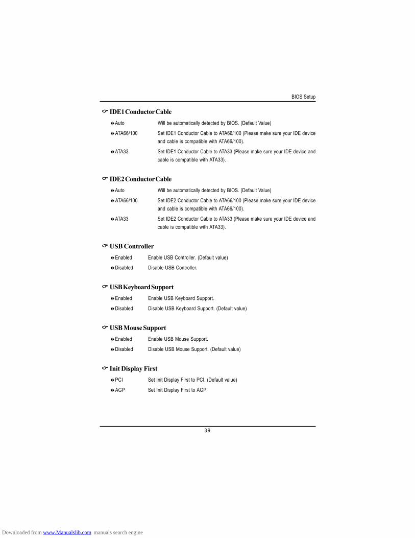
IDE1 Conductor CableAuto Will be automatically detected by BIOS. (Default Value)
ATA66/100 Set IDE1 Conductor Cable to ATA66/100 (Please make sure your IDE deviceand cable is compatible with ATA66/100).
ATA33 Set IDE1 Conductor Cable to ATA33 (Please make sure your IDE device andcable is compatible with ATA33).
IDE2 Conductor CableAuto Will be automatically detected by BIOS. (Default Value)
ATA66/100 Set IDE2 Conductor Cable to ATA66/100 (Please make sure your IDE deviceand cable is compatible with ATA66/100).
ATA33 Set IDE2 Conductor Cable to ATA33 (Please make sure your IDE device andcable is compatible with ATA33).
USB ControllerEnabled Enable USB Controller. (Default value)
Disabled Disable USB Controller.
USB Keyboard SupportEnabled Enable USB Keyboard Support.
Disabled Disable USB Keyboard Support. (Default value)
USB Mouse SupportEnabled Enable USB Mouse Support.
Disabled Disable USB Mouse Support. (Default value)
Init Display FirstPCI Set Init Display First to PCI. (Default value)
AGP Set Init Display First to AGP.
Downloaded from www.Manualslib.com manuals search engine
GA-6OXT(-A) Motherboard
4 0
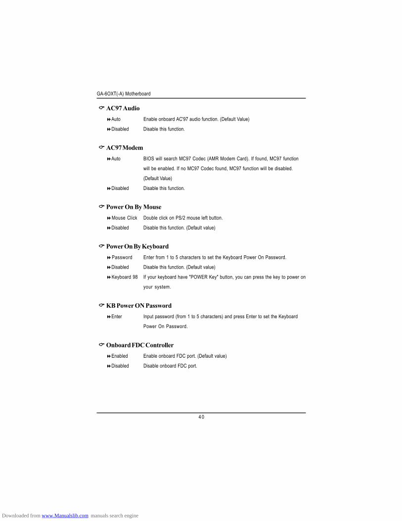
AC97 AudioAuto Enable onboard AC'97 audio function. (Default Value)
Disabled Disable this function.
AC97 ModemAuto BIOS will search MC97 Codec (AMR Modem Card). If found, MC97 function
will be enabled. If no MC97 Codec found, MC97 function will be disabled.
(Default Value)
Disabled Disable this function.
Power On By MouseMouse Click Double click on PS/2 mouse left button.
Disabled Disable this function. (Default value)
Power On By KeyboardPassword Enter from 1 to 5 characters to set the Keyboard Power On Password.
Disabled Disable this function. (Default value)
Keyboard 98 If your keyboard have "POWER Key" button, you can press the key to power on
your system.
KB Power ON PasswordEnter Input password (from 1 to 5 characters) and press Enter to set the Keyboard
Power On Password.
Onboard FDC ControllerEnabled Enable onboard FDC port. (Default value)
Disabled Disable onboard FDC port.
Downloaded from www.Manualslib.com manuals search engine
BIOS Setup
4 1
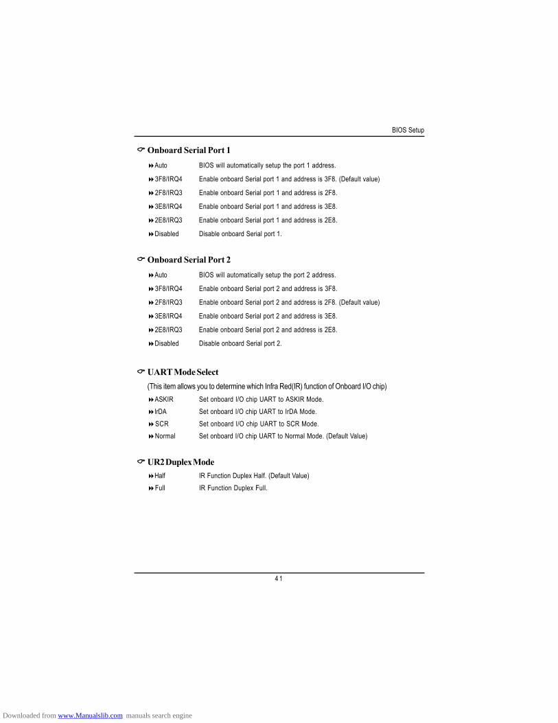
Onboard Serial Port 1Auto BIOS will automatically setup the port 1 address.
3F8/IRQ4 Enable onboard Serial port 1 and address is 3F8. (Default value)
2F8/IRQ3 Enable onboard Serial port 1 and address is 2F8.
3E8/IRQ4 Enable onboard Serial port 1 and address is 3E8.
2E8/IRQ3 Enable onboard Serial port 1 and address is 2E8.
Disabled Disable onboard Serial port 1.
Onboard Serial Port 2Auto BIOS will automatically setup the port 2 address.
3F8/IRQ4 Enable onboard Serial port 2 and address is 3F8.
2F8/IRQ3 Enable onboard Serial port 2 and address is 2F8. (Default value)
3E8/IRQ4 Enable onboard Serial port 2 and address is 3E8.
2E8/IRQ3 Enable onboard Serial port 2 and address is 2E8.
Disabled Disable onboard Serial port 2.
UART Mode Select(This item allows you to determine which Infra Red(IR) function of Onboard I/O chip)
ASKIR Set onboard I/O chip UART to ASKIR Mode.IrDA Set onboard I/O chip UART to IrDA Mode.SCR Set onboard I/O chip UART to SCR Mode.Normal Set onboard I/O chip UART to Normal Mode. (Default Value)
UR2 Duplex ModeHalf IR Function Duplex Half. (Default Value)Full IR Function Duplex Full.
Downloaded from www.Manualslib.com manuals search engine
GA-6OXT(-A) Motherboard
4 2
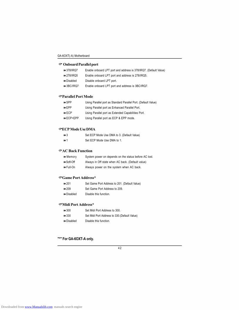
Onboard Parallel port378/IRQ7 Enable onboard LPT port and address is 378/IRQ7. (Default Value)278/IRQ5 Enable onboard LPT port and address is 278/IRQ5.Disabled Disable onboard LPT port.3BC/IRQ7 Enable onboard LPT port and address is 3BC/IRQ7.
Parallel Port ModeSPP Using Parallel port as Standard Parallel Port. (Default Value)EPP Using Parallel port as Enhanced Parallel Port.ECP Using Parallel port as Extended Capabilities Port.ECP+EPP Using Parallel port as ECP & EPP mode.
ECP Mode Use DMA3 Set ECP Mode Use DMA to 3. (Default Value)1 Set ECP Mode Use DMA to 1.
AC Back FunctionMemory System power on depends on the status before AC lost.Soft-Off Always in Off state when AC back. (Default value)Full-On Always power on the system when AC back.
Game Port Address*201 Set Game Port Address to 201. (Default Value)209 Set Game Port Address to 209.Disabled Disable this function.
Midi Port Address*300 Set Midi Port Address to 300.330 Set Midi Port Address to 330.(Default Value)Disabled Disable this function.
"*" For GA-6OXT-A only.
Downloaded from www.Manualslib.com manuals search engine
BIOS Setup
4 3
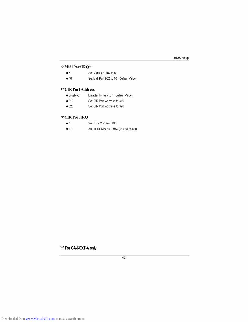
Midi Port IRQ*5 Set Midi Port IRQ to 5.10 Set Midi Port IRQ to 10. (Default Value)
CIR Port AddressDisabled Disable this function. (Default Value)310 Set CIR Port Address to 310.320 Set CIR Port Address to 320.
CIR Port IRQ5 Set 5 for CIR Port IRQ.11 Set 11 for CIR Port IRQ. (Default Value)
"*" For GA-6OXT-A only.
Downloaded from www.Manualslib.com manuals search engine
GA-6OXT(-A) Motherboard
4 4
Power Management Setup
Figure 6: Power Management Setup
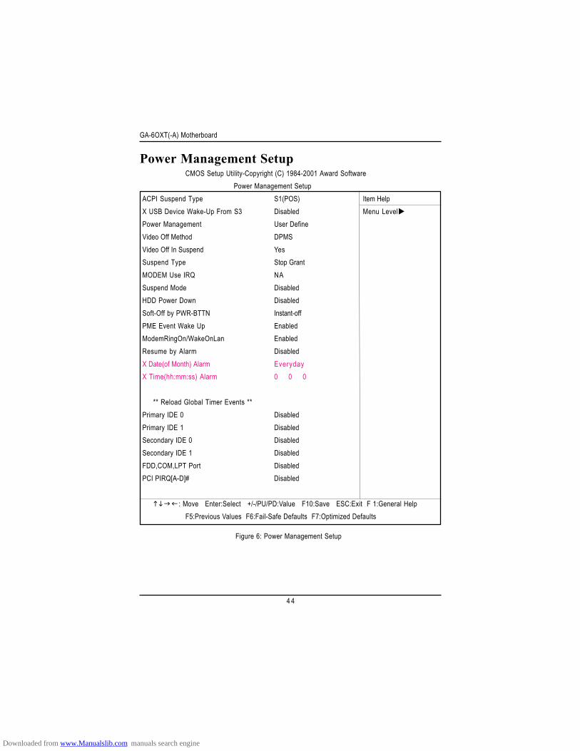
CMOS Setup Utility-Copyright (C) 1984-2001 Award SoftwarePower Management Setup
ACPI Suspend Type S1(POS) Item HelpX USB Device Wake-Up From S3 Disabled Menu LevelPower Management User DefineVideo Off Method DPMSVideo Off In Suspend YesSuspend Type Stop GrantMODEM Use IRQ NASuspend Mode DisabledHDD Power Down DisabledSoft-Off by PWR-BTTN Instant-offPME Event Wake Up EnabledModemRingOn/WakeOnLan EnabledResume by Alarm DisabledX Date(of Month) Alarm EverydayX Time(hh:mm:ss) Alarm 0 0 0
** Reload Global Timer Events **Primary IDE 0 DisabledPrimary IDE 1 DisabledSecondary IDE 0 DisabledSecondary IDE 1 DisabledFDD,COM,LPT Port DisabledPCI PIRQ[A-D]# Disabled
: Move Enter:Select +/-/PU/PD:Value F10:Save ESC:Exit F 1:General HelpF5:Previous Values F6:Fail-Safe Defaults F7:Optimized Defaults
Downloaded from www.Manualslib.com manuals search engine
BIOS Setup
4 5
ACPI Suspend TypeS1(POS) Set ACPI suspend type to S1. (Default Value)
S3(STR) Set ACPI suspend type to S3.
USB Device Wake-Up From S3Enabled Enable USB Device Wakeup From S3.
Disabled Disable USB Device Wakeup From S3. (Default value)
Power ManagementUser Define For configuring our own power management features. (Default Value)
Min Saving Disable Green & software APM function.
Max Saving Enable Green & software APM function.
Video off MethodV/H SYNC+Blank BIOS will turn off V/H-SYNC when gets into Green mode for Green monitor
power saving.
Blank Screen BIOS will only black monitor when gets into Green mode.
DPMS BIOS will use DPMS Standard to control VGA card. (The Green type VGAcard will turn off V/H-SYNC automatically.)(Default value)
Video Off In SuspendYes Enable Video Off In Suspend function. (Default value)
No Disable this function.
Suspend TypeStop Grant Set Suspend Type to stop grant. (Default value)
PwrOn Suspend Set Suspend Type to Power on Suspend.
Downloaded from www.Manualslib.com manuals search engine
GA-6OXT(-A) Motherboard
4 6
MODEM Use IRQN/A Set MODEM Use IRQ to NA.(Default value)
3 Set MODEM Use IRQ to 3.
4 Set MODEM Use IRQ to 4.
5 Set MODEM Use IRQ to 5.
7 Set MODEM Use IRQ to 7.
9 Set MODEM Use IRQ to 9.
10 Set MODEM Use IRQ to 10.
11 Set MODEM Use IRQ to 11.
Suspend ModeDisabled Disable Suspend Mode. (Default value)
1 min - 1 Hour Setup the timer to enter Suspend Mode.
HDD Power DownDisabled Disable HDD Power Down mode function. (Default value)
1-15 mins. Enable HDD Power Down mode between 1 to 15 mins.
Soft-off by PWR-BTTNInstant-off Press power button then Power off instantly. (Default value)
Delay 4 Sec. Press power button 4 sec to Power off. Enter suspend if button is pressed less
than 4 sec.
PME Event Wake UPDisabled Disable this function.
Enabled Enable PME Event Wake up. (Default Value)
Modem Ring On/Wake On LANDisabled Disable Modem Ring on/wake on Lan function.
Enabled Enable Modem Ring on/wake on Lan. (Default Value)
Downloaded from www.Manualslib.com manuals search engine
BIOS Setup
4 7
Resume by AlarmYou can set "Resume by Alarm" item to enabled and key in Data/time to power on system.
Disabled Disable this function. (Default Value)
Enabled Enable alarm function to POWER ON system.
If RTC Alarm Lead To Power On is Enabled.
Date ( of Month) Alarm : Everyday, 1~31
Time ( hh: mm: ss) Alarm : (0~23) : (0~59) : (0~59)
Primary IDE 0/1Disabled Disable this function. (Default value)
Enabled Enable monitor Primary IDE 0/1 for Green event.
Secondary IDE 0/1Disabled Disable this function. (Default value)
Enabled Enable monitor Secondary IDE 0/1 for Green event.
FDD,COM,LPT PortDisabled Disable this function. (Default value)
Enabled Enable monitor FDC,COM,LPT for Green event.
PCI PIRQ[A-D] #Enabled Monitor PCI PIRQ[A-D]# IRQ Active.
Disabled Ignore PCI PIRQ[A-D]# IRQ Active. (Default value)
Downloaded from www.Manualslib.com manuals search engine
GA-6OXT(-A) Motherboard
4 8
PnP/PCI Configurations
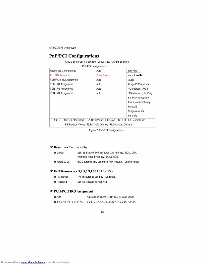
Figure 7: PnP/PCI Configurations
Resources Controlled byManual User can set the PnP resource (I/O Address, IRQ & DMA
channels) used by legacy ISA DEVICE.
Auto(ESCD) BIOS automatically use these PnP rescuers. (Default value)
IRQ Resources ( 3,4,5,7,9,10,11,12,14,15 )PCI Device The resource is used by PCI device.
Reserved Set the resource to reserved.
PCI1/PCI5 IRQ AssignmentAuto Auto assign IRQ to PCI1/PCI5. (Default value)
3,4,5,7,9.,10,11,12,14,15 Set IRQ 3,4,5,7,9,10,11,12,14,15 to PCI1/PCI5.
CMOS Setup Utility-Copyright (C) 1984-2001 Award SoftwarePnP/PCI Configurations
Resources Controlled By Auto Item HelpX IRQ Resources Press Enter Menu LevelPCI1/PCI5 IRQ Assignment Auto [Auto]PCI2 IRQ Assignment Auto Assign PnP resourcePCI3 IRQ Assignment Auto (I/O address, IRQ &PCI4 IRQ Assignment Auto DMA channels) for Plug
and Play compatibledevices automatically[Manual]Assign resourcemanually
: Move Enter:Select +/-/PU/PD:Value F10:Save ESC:Exit F1:General HelpF5:Previous Values F6:Fail-Safe Defaults F7:Optimized Defaults
Downloaded from www.Manualslib.com manuals search engine
BIOS Setup
4 9
PCI2 IRQ AssignmentAuto Auto assign IRQ to PCI2. (Default value)3,4,5,7,9.,10,11,12,14,15 Set IRQ 3,4,5,7,9,10,11,12,14,15 to PCI2.
PCI3 IRQ AssignmentAuto Auto assign IRQ to PCI3. (Default value)
3,4,5,7,9.,10,11,12,14,15 Set IRQ 3,4,5,7,9,10,11,12,14,15 to PCI3.
PCI4 IRQ AssignmentAuto Auto assign IRQ to PCI4. (Default value)
3,4,5,7,9.,10,11,12,14,15 Set IRQ 3,4,5,7,9,10,11,12,14,15 to PCI4.
Downloaded from www.Manualslib.com manuals search engine
GA-6OXT(-A) Motherboard
5 0
PC Health Status
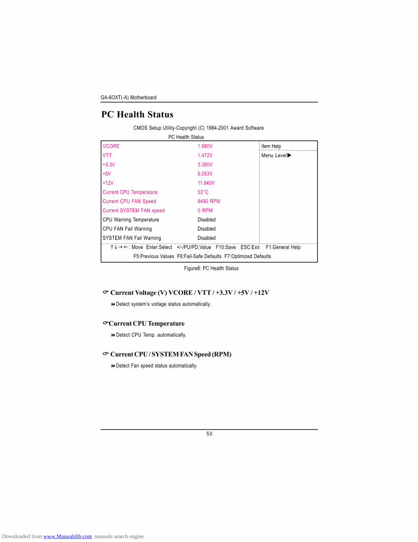
Figure8: PC Health Status
Current Voltage (V) VCORE / VTT / +3.3V / +5V / +12VDetect system’s voltage status automatically.
Current CPU TemperatureDetect CPU Temp. automatically.
Current CPU / SYSTEM FAN Speed (RPM)Detect Fan speed status automatically.
CMOS Setup Utility-Copyright (C) 1984-2001 Award SoftwarePC Health Status
VCORE 1.680V Item HelpVTT 1.472V Menu Level+3.3V 3.360V+5V 5.053V+12V 11.840VCurrent CPU Temperature 53°CCurrent CPU FAN Speed 6490 RPMCurrent SYSTEM FAN speed 0 RPMCPU Warning Temperature DisabledCPU FAN Fail Warning DisabledSYSTEM FAN Fail Warning Disabled
: Move Enter:Select +/-/PU/PD:Value F10:Save ESC:Exit F1:General HelpF5:Previous Values F6:Fail-Safe Defaults F7:Optimized Defaults
Downloaded from www.Manualslib.com manuals search engine
BIOS Setup
5 1
CPU Warning Temperature60°C / 140°F Monitor CPU Temp. at 60°C / 140°F.
70°C / 158°F Monitor CPU Temp. at 70°C / 158°F.
80°C / 176°F Monitor CPU Temp. at 80°C / 176°F.
90°C / 194°F Monitor CPU Temp. at 90°C / 194°F.
Disabled Disable this function.(Default value)
Fan Fail Warning ( CPU / SYSTEM)Disabled Fan Warning Function Disable. (Default value)
Enabled Fan Warning Function Enable.
Downloaded from www.Manualslib.com manuals search engine
GA-6OXT(-A) Motherboard
5 2
Frequency/Voltage Control
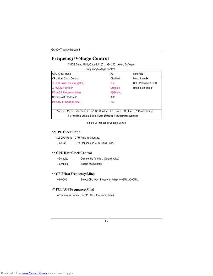
Figure 9: Frequency/Voltage Control
CPU Clock RatioSet CPU Ratio if CPU Ratio is unlocked.
X3~X8 It’s depends on CPU Clock Ratio.
CPU Host Clock ControlDisabled Disable this function. (Default value)
Enabled Enable this function.
CPU Host Frequency(Mhz)66~200 Select CPU Host Frequency(Mhz) to 66Mhz~200Mhz.
PCI/AGP Frequency(Mhz)The values depend on CPU Host Frequency(Mhz) .
CMOS Setup Utility-Copyright (C) 1984-2001 Award SoftwareFrequency/Voltage Control
CPU Clock Ratio X3 Item HelpCPU Host Clock Control Disabled Menu LevelX CPU Host Frequency(Mhz) 133 Set CPU Ratio if CPUX PCI/AGP Divider Disabled Ratio is unlockedPCI/AGP Frequency(Mhz) 33/66MHzHost/DRAM Clock ratio AutoMemory Frequency(Mhz) 133
: Move Enter:Select +/-/PU/PD:Value F10:Save ESC:Exit F1:General HelpF5:Previous Values F6:Fail-Safe Defaults F7:Optimized Defaults
Downloaded from www.Manualslib.com manuals search engine
BIOS Setup
5 3
PCI/AGP DividerYou can choose Disabled,PLL/40,PLL/32,PLL/24,PLL/20/PLL/16 mode to adjust PCI/AGP
frequency.
PCI/AGP Frequency(Mhz)Setup PCI/AGP frequency by adjusting CPU Host Frequency or PCI/AGP Divider item.
Host/DRAM Clock Ratio(Warning: wrong frequency may make system can’t boot, clear CMOS to overcome wrong frequency issue)
0.75 Memory Frequency = Host clock X 0.75.
1.00 Memory Frequency = Host clock X 1.00.
Auto Set Memory frequency by DRAM SPD data. (Default value)
Memory Frequency(Mhz)The values depend on CPU Host Frequency(Mhz) .
Downloaded from www.Manualslib.com manuals search engine
GA-6OXT(-A) Motherboard
5 4
Load Fail-Safe Defaults
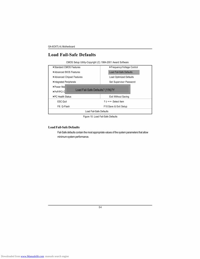
Load Fail-Safe DefaultsFail-Safe defaults contain the most appropriate values of the system parameters that allowminimum system performance.
Figure 10: Load Fail-Safe Defaults
CMOS Setup Utility-Copyright (C) 1984-2001 Award Software
Standard CMOS Features Frequency/Voltage Control
Advanced BIOS Features Load Fail-Safe Defaults
Advanced Chipset Features Load Optimized Defaults
Integrated Peripherals Set Supervisor Password
Power Management Setup Set User Password
PnP/PCI Configurations Save & Exit Setup
PC Health Status Exit Without Saving
ESC:Quit :Select Item
F8: Q-Flash F10:Save & Exit Setup
Load Fail-Safe Defaults
Load Fail-Safe Defaults? (Y/N)?Y
Downloaded from www.Manualslib.com manuals search engine
BIOS Setup
5 5
Load Optimized Defaults
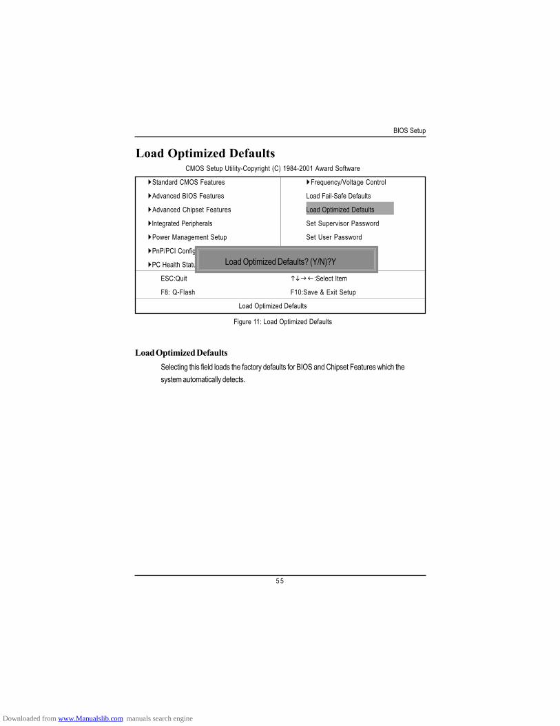
Load Optimized DefaultsSelecting this field loads the factory defaults for BIOS and Chipset Features which thesystem automatically detects.
Figure 11: Load Optimized Defaults
CMOS Setup Utility-Copyright (C) 1984-2001 Award Software
Standard CMOS Features Frequency/Voltage Control
Advanced BIOS Features Load Fail-Safe Defaults
Advanced Chipset Features Load Optimized Defaults
Integrated Peripherals Set Supervisor Password
Power Management Setup Set User Password
PnP/PCI Configurations Save & Exit Setup
PC Health Status Exit Without Saving
ESC:Quit :Select Item
F8: Q-Flash F10:Save & Exit Setup
Load Optimized Defaults
Load Optimized Defaults? (Y/N)?Y
Downloaded from www.Manualslib.com manuals search engine

GA-6OXT(-A) Motherboard
5 6
Set Supervisor/User Password
When you select this function, the following message will appear at the center of the screen to assistyou in creating a password.
Type the password, up to eight characters, and press <Enter>. You will be asked to confirm thepassword. Type the password again and press <Enter>. You may also press <Esc> to abort theselection and not enter a password.
To disable password, just press <Enter> when you are prompted to enter password. A message“PASSWORD DISABLED” will appear to confirm the password being disabled. Once the password isdisabled, the system will boot and you can enter Setup freely.
The BIOS Setup program allows you to specify two separate passwords:SUPERVISOR PASSWORD and a USER PASSWORD. When disabled, anyone may access
all BIOS Setup program function. When enabled, the Supervisor password is required for entering theBIOS Setup program and having full configuration fields, the User password is required to access onlybasic items.
If you select “System” at “Password Check” in Advance BIOS Features Menu, you will beprompted for the password every time the system is rebooted or any time you try to enter Setup Menu.
If you select “Setup” at “Password Check” in Advance BIOS Features Menu, you will be promptedonly when you try to enter Setup.
Figure 12: Password Setting
CMOS Setup Utility-Copyright (C) 1984-2001 Award Software
Standard CMOS Features Frequency/Voltage Control
Advanced BIOS Features Load Fail-Safe Defaults
Advanced Chipset Features Load Optimized Defaults
Integrated Peripherals Set Supervisor Password
Power Management Setup Set User Password
PnP/PCI Configurations Save & Exit Setup
PC Health Status Exit Without Saving
ESC:Quit :Select Item
F8: Q-Flash F10:Save & Exit Setup
Change/Set/Disable Password
Enter Password:
Downloaded from www.Manualslib.com manuals search engine
BIOS Setup
5 7
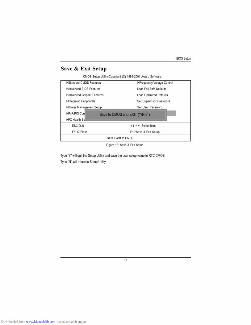
Save & Exit Setup
Type “Y” will quit the Setup Utility and save the user setup value to RTC CMOS.Type “N” will return to Setup Utility.
Figure 13: Save & Exit Setup
CMOS Setup Utility-Copyright (C) 1984-2001 Award Software
Standard CMOS Features Frequency/Voltage Control
Advanced BIOS Features Load Fail-Safe Defaults
Advanced Chipset Features Load Optimized Defaults
Integrated Peripherals Set Supervisor Password
Power Management Setup Set User Password
PnP/PCI Configurations Save & Exit Setup
PC Health Status Exit Without Saving
ESC:Quit :Select Item
F8: Q-Flash F10:Save & Exit Setup
Save Datat to CMOS
Save to CMOS and EXIT (Y/N)? Y
Downloaded from www.Manualslib.com manuals search engine
GA-6OXT(-A) Motherboard
5 8
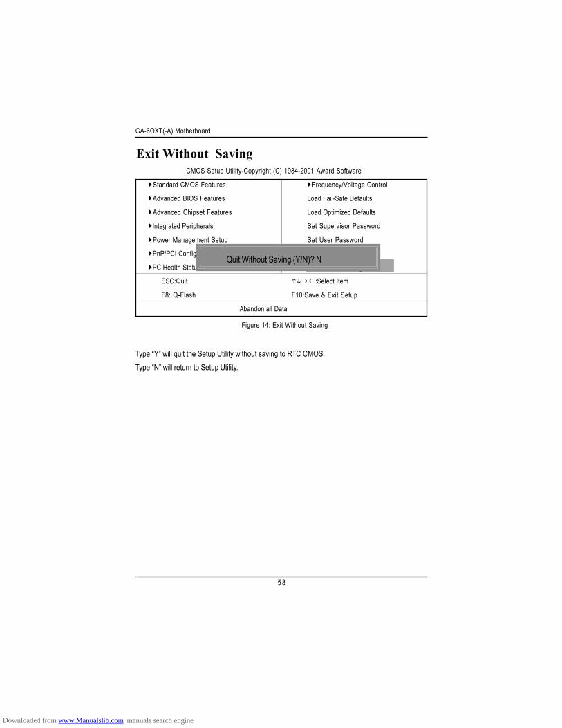
Exit Without Saving
Type “Y” will quit the Setup Utility without saving to RTC CMOS.Type “N” will return to Setup Utility.
Figure 14: Exit Without Saving
CMOS Setup Utility-Copyright (C) 1984-2001 Award Software
Standard CMOS Features Frequency/Voltage Control
Advanced BIOS Features Load Fail-Safe Defaults
Advanced Chipset Features Load Optimized Defaults
Integrated Peripherals Set Supervisor Password
Power Management Setup Set User Password
PnP/PCI Configurations Save & Exit Setup
PC Health Status Exit Without Saving
ESC:Quit :Select Item
F8: Q-Flash F10:Save & Exit Setup
Abandon all Data
Quit Without Saving (Y/N)? N
Downloaded from www.Manualslib.com manuals search engine
5 9
Technical Reference
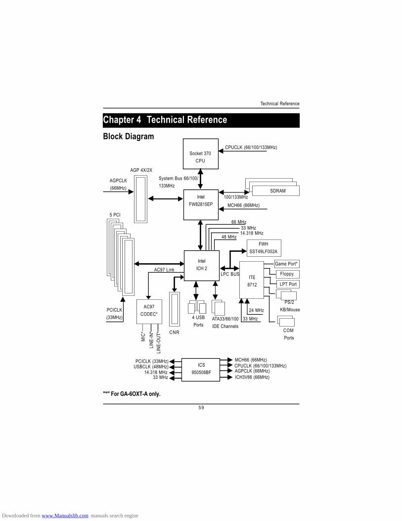
Revision HistoryChapter 4 Technical ReferenceBlock Diagram
Socket 370CPU
IntelFW82815EP
ITE8712
FWHSST49LF002A
CPUCLK (66/100/133MHz)
System Bus 66/100/133MHz
SDRAM100/133MHz
MCH66 (66MHz)
66 MHz33 MHz14.318 MHz
48 MHz
24 MHz33 MHz
LPC BUS
AGP 4X/2X
AGPCLK(66MHz)
5 PCI
PCICLK(33MHz) 4 USB
PortsATA33/66/100IDE Channels
Floppy
LPT Port
PS/2 KB/Mouse
COM Ports
CNR
IntelICH 2
ICS950508BF
MCH66 (66MHz)CPUCLK (66/100/133MHz)AGPCLK (66MHz)ICH3V66 (66MHz)
PCICLK (33MHz)USBCLK (48MHz)
14.318 MHz33 MHz
Game Port*
AC97CODEC*
AC97 Link
MIC
*LI
NE-IN
*LI
NE-O
UT*
"*" For GA-6OXT-A only.
Downloaded from www.Manualslib.com manuals search engine
GA-6OXT(-A) Motherboard
6 0
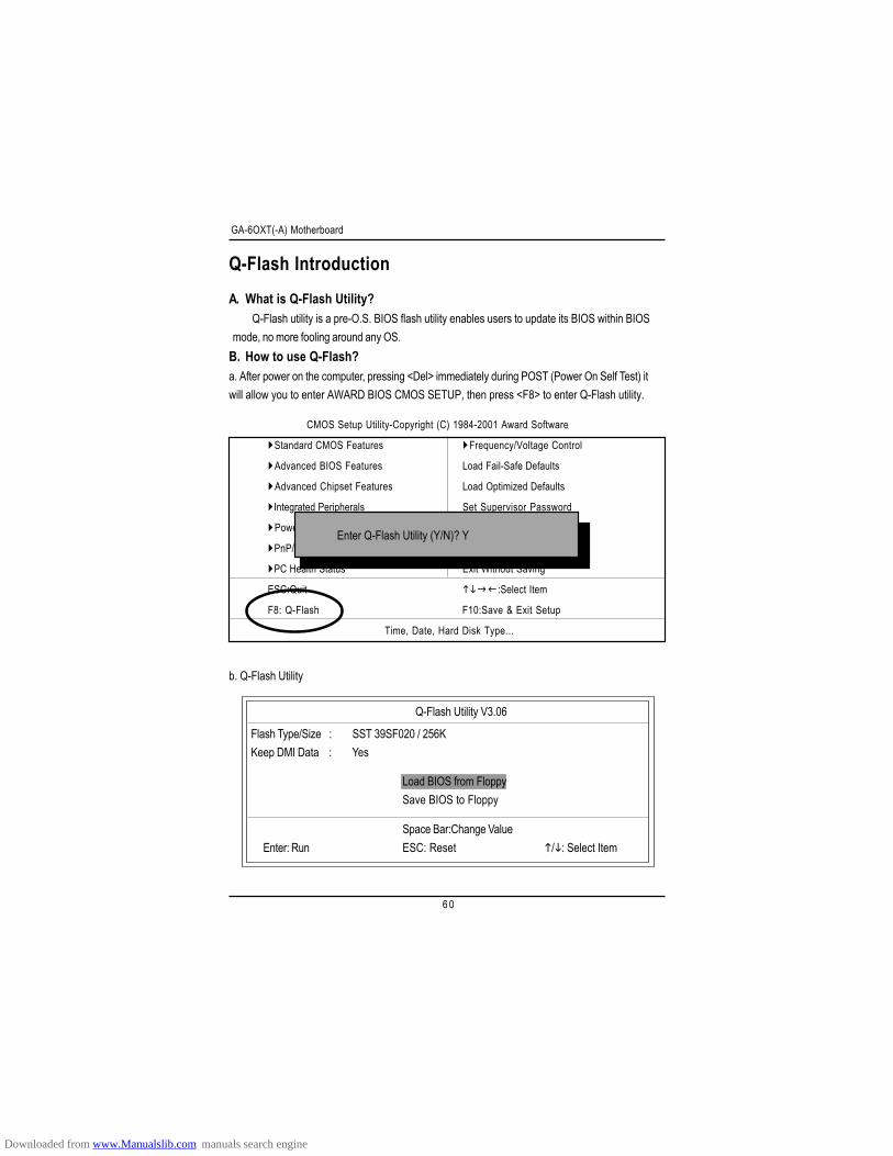
Q-Flash IntroductionA. What is Q-Flash Utility?
Q-Flash utility is a pre-O.S. BIOS flash utility enables users to update its BIOS within BIOSmode, no more fooling around any OS.
B. How to use Q-Flash?a. After power on the computer, pressing <Del> immediately during POST (Power On Self Test) itwill allow you to enter AWARD BIOS CMOS SETUP, then press <F8> to enter Q-Flash utility.
b. Q-Flash Utility
Q-Flash Utility V3.06
Flash Type/Size : SST 39SF020 / 256KKeep DMI Data : Yes
Space Bar:Change ValueEnter: Run ESC: Reset / : Select Item
Load BIOS from FloppySave BIOS to Floppy
CMOS Setup Utility-Copyright (C) 1984-2001 Award Software
Standard CMOS Features Frequency/Voltage Control
Advanced BIOS Features Load Fail-Safe Defaults
Advanced Chipset Features Load Optimized Defaults
Integrated Peripherals Set Supervisor Password
Power Management Setup Set User Password
PnP/PCI Configurations Save & Exit Setup
PC Health Status Exit Without Saving
ESC:Quit :Select Item
F8: Q-Flash F10:Save & Exit Setup
Time, Date, Hard Disk Type...
Enter Q-Flash Utility (Y/N)? Y
Downloaded from www.Manualslib.com manuals search engine
6 1
Technical Reference
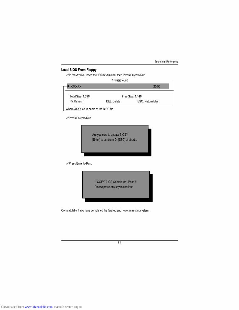
Congratulation! You have completed the flashed and now can restart system.
Load BIOS From FloppyIn the A:drive, insert the "BIOS" diskette, then Press Enter to Run.
XXXX.XX 256K
Total Size: 1.39M Free Size: 1.14MF5: Refresh DEL: Delete ESC: Return Main
Press Enter to Run.
1 File(s) found
Are you sure to update BIOS?[Enter] to contiune Or [ESC] ot abort...
!! COPY BIOS Completed -Pass !!Please press any key to continue
Press Enter to Run.
Where XXXX.XX is name of the BIOS file.
Downloaded from www.Manualslib.com manuals search engine

GA-6OXT(-A) Motherboard
6 2
@ BIOSTM IntroductionGigabyte announces @ BIOSWindows BIOS live update utility
Have you ever updated BIOS by yourself? Or likemany other people, you just know what BIOS is,but always hesitate to update it? Because you thinkupdating newest BIOS is unnecessary and actuallyyou don’t know how to update it.
Maybe not like others, you are very experienced in BIOS updating and spend quite a lot of timeto do it. But of course you don’t like to do it too much. First, download different BIOS from website andthen switch the operating system to DOS mode. Secondly, use different flash utility to update BIOS.The above process is not a interesting job. Besides, always be carefully to store the BIOS sourcecode correctly in your disks as if you update the wrong BIOS, it will be a nightmare.
Certainly, you wonder why motherboard vendors could not just do something right to save yourtime and effort and save you from the lousy BIOS updating work? Here it comes! Now Gigabyteannounces @BIOS—the first Windows BIOS live update utility. This is a smart BIOS updatesoftware. It could help you to download the BIOS from internetand update it. Not like the other BIOSupdate software, it’s a Windows utility. With the help of “@BIOS’, BIOS updating is no more than aclick.
Besides, no matter which mainboard you are using, if it’s a Gigabyte’s product*, @BIOS helpyou to maintain the BIOS. This utility could detect your correct mainboard model and help you tochoose the BIOS accordingly. It then downloads the BIOS from the nearest Gigabyte ftp siteautomatically. There are several different choices; you could use “Internet Update” to download andupdate your BIOS directly. Or you may want to keep a backup for your current BIOS, just choose“Save Current BIOS” to save it first. You make a wise choice to use Gigabyte, and @BIOS updateyour BIOS smartly. You are now worry free from updating wrong BIOS, and capable to maintain andmanage your BIOS easily. Again, Gigabyte’s innovative product erects a milestone in mainboardindustries.
For such a wonderful software, how much it costs? Impossible! It’s free! Now, if you buy aGigabyte’s motherboard, you could find this amazing software in the attached driver CD. But pleaseremember, connected to internet at first, then you could have a internet BIOS update from yourGigabyte @BIOS.
Downloaded from www.Manualslib.com manuals search engine

6 3
Technical Reference
Easy TuneIIITM IntroductionGigabyte announces EasyTuneIIIWindows overdrive utility
“Overdrive” might be one of the mostcommon issues in computer field. But have manyusers ever tried it? The answer is probably “no”.Because “overdrive” is thought to be very difficult andincludes a lot of technical know-how, sometimes “over-
drive” is even considered as special skills found only in some enthusiasts.But as to the experts in “overdrive”, what’s the truth? They may spend quite a lot of time and money
to study, try and use many different hardware and software tools to do “overdrive”. And even with thesetechnologies, they still learn that it’s quite a risk because the safety and stability of an “overdrive“ systemis unknown.
Now everything is different because of a Windows overdrive utility EasyTuneIII—announced byGigabyte. This utility has totally changed the gaming rule of “overdrive”. This is the first overdrive utilitysuitable for both normal and power users. Users can choose either “Easy Mode” or “Advanced Mode”to run “overdrive” at their convenience. For users who choose “Easy Mode”, they just need to click“Auto Optimize” to have auto and immediate CPU overclocking. This software will then overdrive CPUspeed automatically with the result being shown in the control panel. If someone prefers to “overdrive” byoneself, there is also another choice. Click “Advanced Mode” to enjoy “sport drive” class overclocking.In “Advanced Mode”, one can change the system bus speed in small increments to get ultimate systemperformance. And no matter which mainboard is used, if it’s a Gigabyte’s product*, EasyTuneIII helps toperform the best of system.
Besides, different from other traditional over-clocking methods, EasyTuneIII doesn’t require users tochange neither BIOS nor hardware switch/ jumper setting; on the other hand, they can do “overdrive” atonly one click. Therefore, this is a safer way for “overdrive” as nothing is changed on software orhardware. If user runs EasyTuneIII over system’s limitation, the biggest lost is only to restart thecomputer again and the side effect is then well controlled. Moreover, if one well-performed system speedbeen tested in EasyTuneIII, user can “Save” this bus speed and “Load” it in next time. Obviously,Gigabyte EasyTuneIII has already turned the “overdrive” technology toward to a newer generation.
This wonderful software is now free bundled in Gigabyte motherboard attached driver CD. Usersmay make a test drive of “EasyTuneIII” to find out more amazing features by themselves.
Downloaded from www.Manualslib.com manuals search engine

GA-6OXT(-A) Motherboard
6 4
Revision HistoryChapter 5 AppendixPicture below are shown in Windows XP (IUCD driver version 2.0)Insert the driver CD-title that came with your motherboard into your CD-ROM driver, the driverCD-title will auto start and show the installation guide. If not, please double click the CD-ROM deviceicon in "My computer", and execute the setup.exe.
A-1. Intel Chipset Software Installation UtilityInsert the driver CD-title that came with your motherboard into your CD-ROM driver, the driverCD-title will auto start and show the installation guide. If not, please double click the CD-ROM deviceicon in "My computer", and execute the setup.exe.
(2)
2.Click "Next".
(1)
1.Click "Intel Chipset SoftwareInstallation Utility" item.
Downloaded from www.Manualslib.com manuals search engine
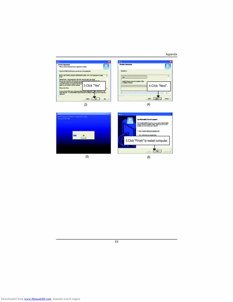
6 5
Appendix
(3)
3.Click "Yes".
(4)
4.Click "Next".
5.Click "Finish" to restart computer.
(5) (6)
Downloaded from www.Manualslib.com manuals search engine
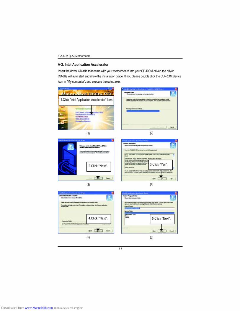
GA-6OXT(-A) Motherboard
6 6
A-2. Intel Application Accelerator
(2)
(3)
(5) (6)
Insert the driver CD-title that came with your motherboard into your CD-ROM driver, the driverCD-title will auto start and show the installation guide. If not, please double click the CD-ROM deviceicon in "My computer", and execute the setup.exe.
(1)
2.Click "Next".
4.Click "Next". 5.Click "Next".
(4)
3.Click "Yes".
1.Click "Intel Application Accelerator" item.
Downloaded from www.Manualslib.com manuals search engine
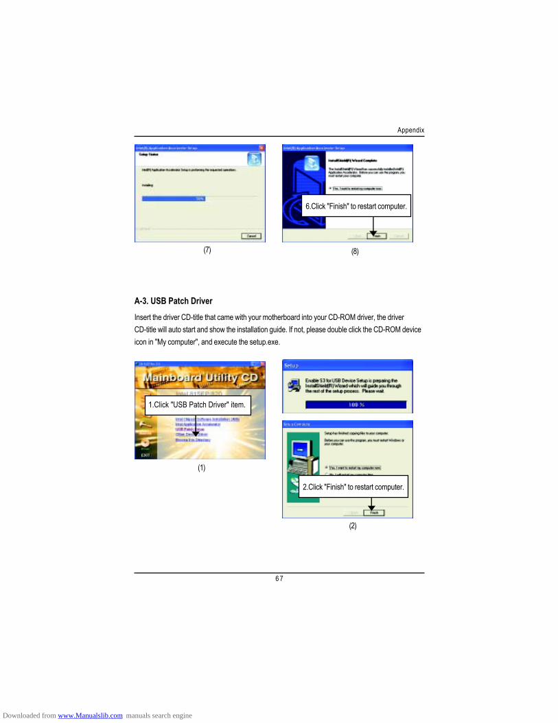
6 7
Appendix
(7) (8)
6.Click "Finish" to restart computer.
A-3. USB Patch DriverInsert the driver CD-title that came with your motherboard into your CD-ROM driver, the driverCD-title will auto start and show the installation guide. If not, please double click the CD-ROM deviceicon in "My computer", and execute the setup.exe.
(1)
(2)
2.Click "Finish" to restart computer.
1.Click "USB Patch Driver" item.
Downloaded from www.Manualslib.com manuals search engine
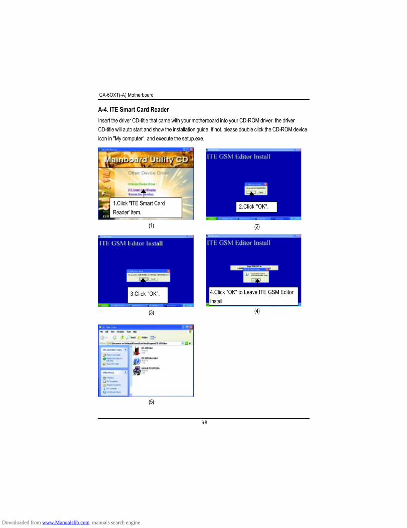
GA-6OXT(-A) Motherboard
6 8
A-4. ITE Smart Card Reader
(2)
(5)
Insert the driver CD-title that came with your motherboard into your CD-ROM driver, the driverCD-title will auto start and show the installation guide. If not, please double click the CD-ROM deviceicon in "My computer", and execute the setup.exe.
(1)
1.Click "ITE Smart CardReader" item.
2.Click "OK".
(3)
3.Click "OK".
(4)
4.Click "OK" to Leave ITE GSM EditorInstall.
Downloaded from www.Manualslib.com manuals search engine
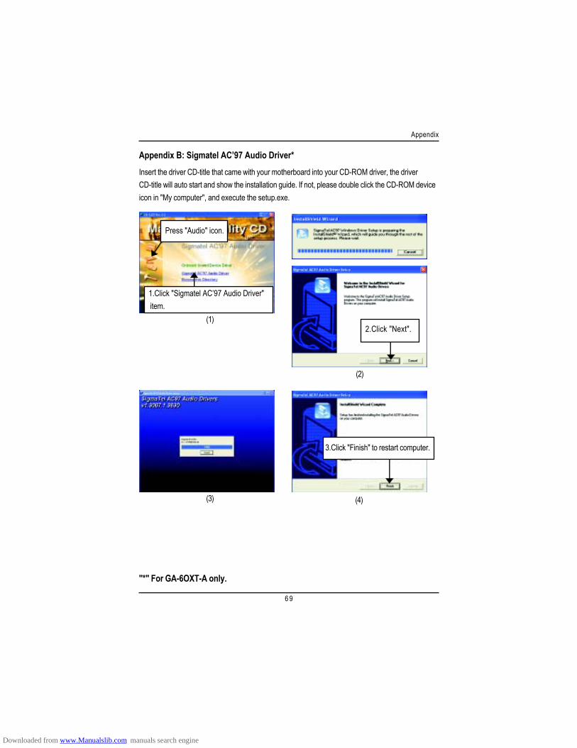
6 9
Appendix
Revision HistoryAppendix B: Sigmatel AC’97 Audio Driver*Insert the driver CD-title that came with your motherboard into your CD-ROM driver, the driverCD-title will auto start and show the installation guide. If not, please double click the CD-ROM deviceicon in "My computer", and execute the setup.exe.
(3) (4)
Press "Audio" icon.
(1)
1.Click "Sigmatel AC’97 Audio Driver" item.
(2)
2.Click "Next".
3.Click "Finish" to restart computer.
"*" For GA-6OXT-A only.
Downloaded from www.Manualslib.com manuals search engine
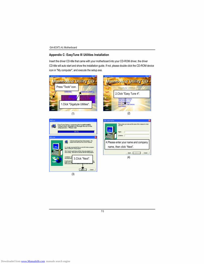
GA-6OXT(-A) Motherboard
7 0
Revision HistoryAppendix C: EasyTune III Utilities Installation
Insert the driver CD-title that came with your motherboard into your CD-ROM driver, the driverCD-title will auto start and show the installation guide. If not, please double click the CD-ROM deviceicon in "My computer", and execute the setup.exe.
(2)(1)
Press "Tools" icon.
1.Click "Gigabyte Utilities".
2.Click "Easy Tune 4".
(3)
3.Click "Next". (4)
4.Please enter your name and company name, then click “Next”.
Downloaded from www.Manualslib.com manuals search engine
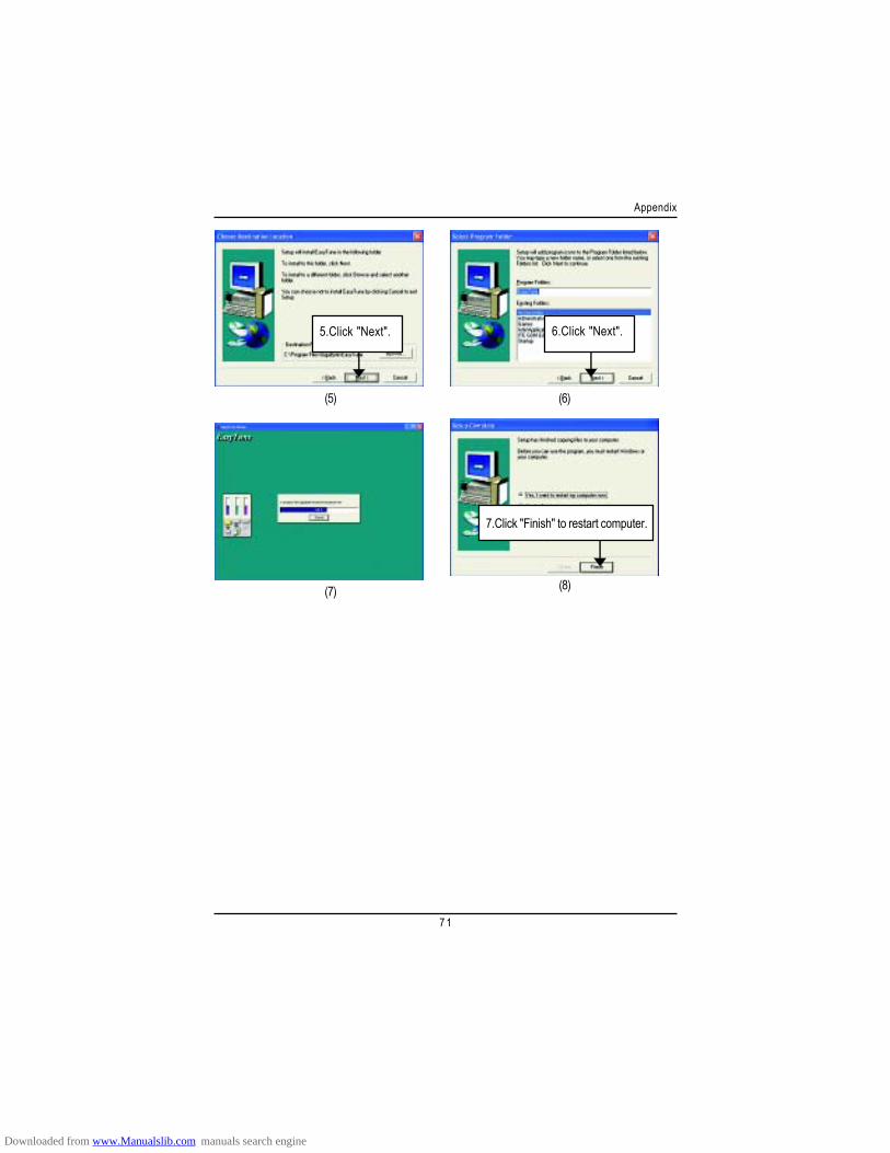
7 1
Appendix
(5)
5.Click "Next".
(6)
(7)
7.Click "Finish" to restart computer.
6.Click "Next".
(8)
Downloaded from www.Manualslib.com manuals search engine
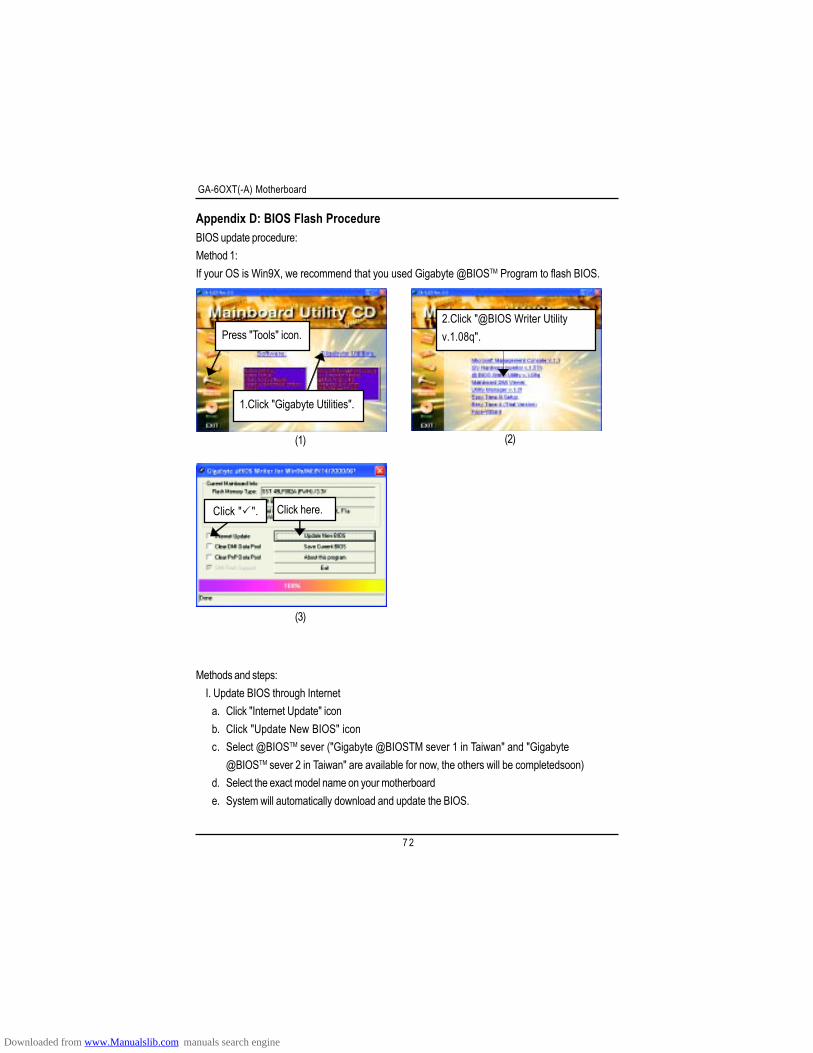
GA-6OXT(-A) Motherboard
7 2
Appendix D: BIOS Flash ProcedureBIOS update procedure:Method 1:If your OS is Win9X, we recommend that you used Gigabyte @BIOSTM Program to flash BIOS.
(2)
Methods and steps: I. Update BIOS through Internet
a. Click "Internet Update" iconb. Click "Update New BIOS" iconc. Select @BIOSTM sever ("Gigabyte @BIOSTM sever 1 in Taiwan" and "Gigabyte
@BIOSTM sever 2 in Taiwan" are available for now, the others will be completedsoon)d. Select the exact model name on your motherboarde. System will automatically download and update the BIOS.
(1)
(3)
Click here.Click " ".
Press "Tools" icon.
1.Click "Gigabyte Utilities".
2.Click "@BIOS Writer Utilityv.1.08q".
Downloaded from www.Manualslib.com manuals search engine
7 3
Appendix
II. Update BIOS NOT through Internet:a. Do not click "Internet Update" iconb. Click "Update New BIOS"c. Please select "All Files" in dialog box while opening the old file.d. Please search for BIOS unzip file, downloading from internet or any other methods (such as:
6OXT.F1).e. Complete update process following the instruction.
III. Save BIOSIn the very beginning, there is "Save Current BIOS" icon shown in dialog box. It means to savethe current BIOS version.
IV. Check out supported motherboard and Flash ROM:In the very beginning, there is "About this program" icon shown in dialog box. It can help youcheck out which kind of motherboard and which brand of Flash ROM are supported.
Note:a. In method I, if it shows two or more motherboard's model names to be selected, please make
sure your motherboard's model name again. Selecting wrong model name will cause thesystem unbooted.
b. In method II, be sure that motherboard's model name in BIOS unzip file are the same as yourmotherboard's. Otherwise, your system won't boot.
c. In method I, if the BIOS file you need cannot be found in @BIOSTM server, please go ontoGigabyte's web site for downloading and updating it according to method II.
d. Please note that any interruption during updating will cause system unbooted
Downloaded from www.Manualslib.com manuals search engine
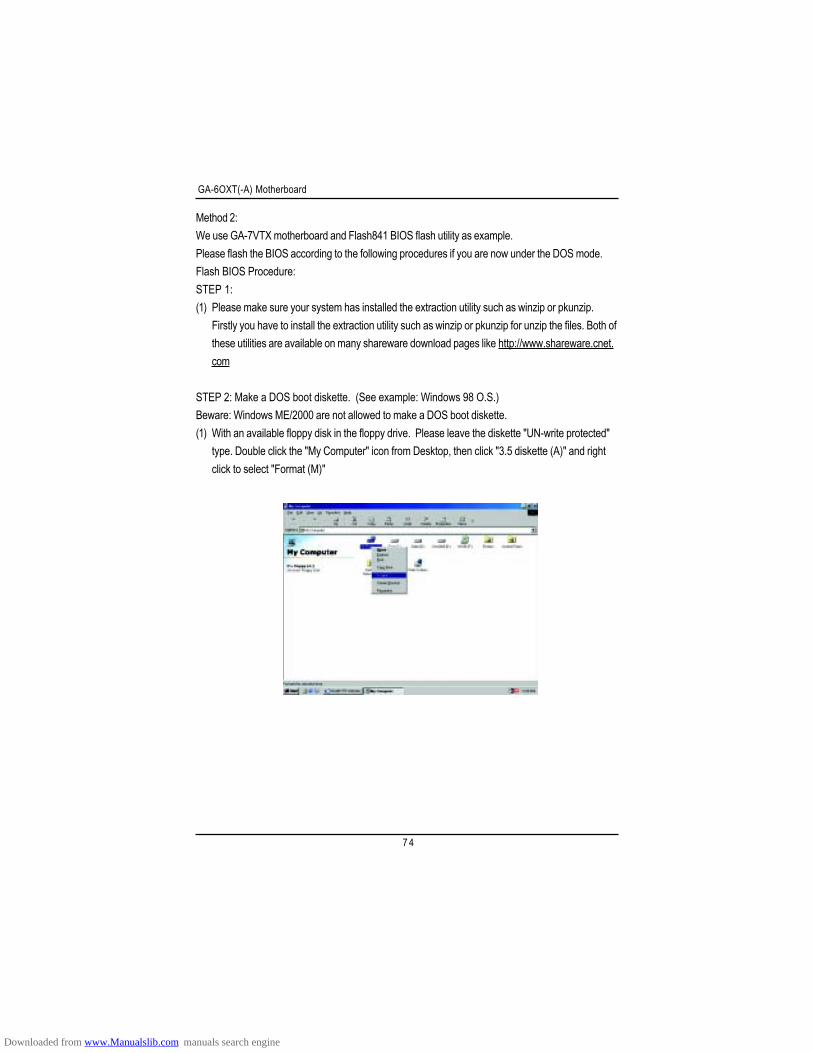
GA-6OXT(-A) Motherboard
7 4
Method 2:We use GA-7VTX motherboard and Flash841 BIOS flash utility as example.Please flash the BIOS according to the following procedures if you are now under the DOS mode.Flash BIOS Procedure:STEP 1:(1) Please make sure your system has installed the extraction utility such as winzip or pkunzip.
Firstly you have to install the extraction utility such as winzip or pkunzip for unzip the files. Both ofthese utilities are available on many shareware download pages like http://www.shareware.cnet.com
STEP 2: Make a DOS boot diskette. (See example: Windows 98 O.S.)Beware: Windows ME/2000 are not allowed to make a DOS boot diskette.(1) With an available floppy disk in the floppy drive. Please leave the diskette "UN-write protected"
type. Double click the "My Computer" icon from Desktop, then click "3.5 diskette (A)" and rightclick to select "Format (M)"
Downloaded from www.Manualslib.com manuals search engine
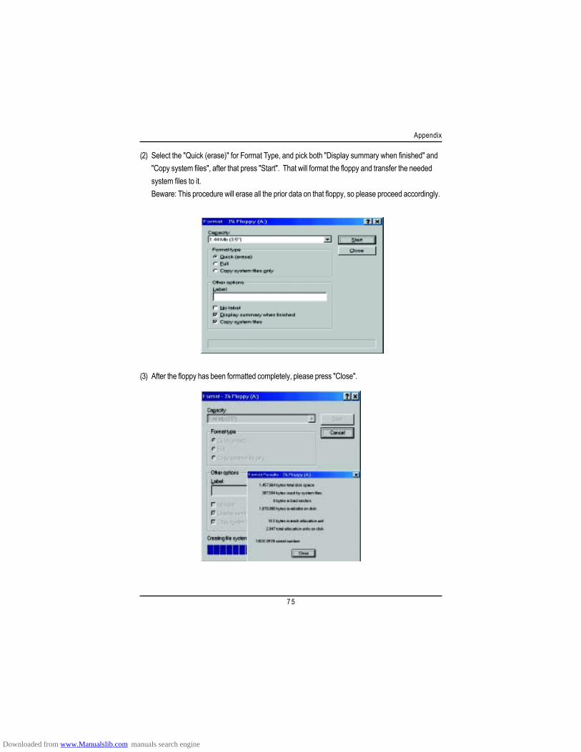
7 5
Appendix
(2) Select the "Quick (erase)" for Format Type, and pick both "Display summary when finished" and"Copy system files", after that press "Start". That will format the floppy and transfer the neededsystem files to it.Beware: This procedure will erase all the prior data on that floppy, so please proceed accordingly.
(3) After the floppy has been formatted completely, please press "Close".
Downloaded from www.Manualslib.com manuals search engine
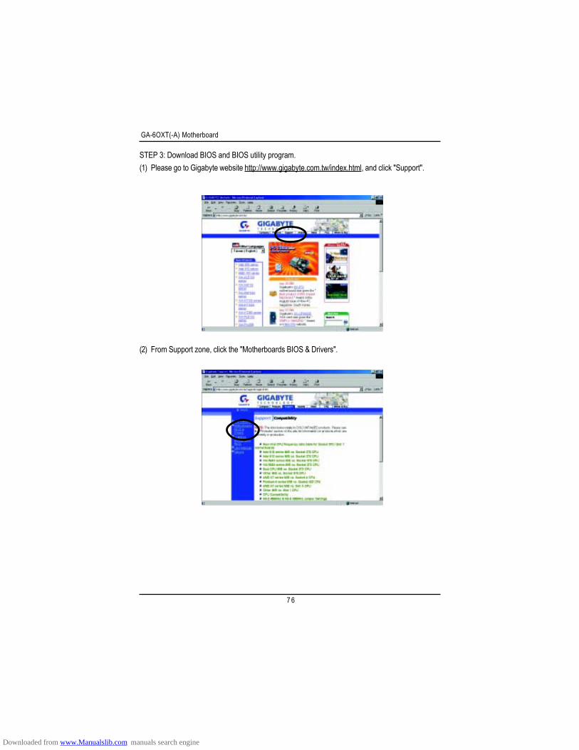
GA-6OXT(-A) Motherboard
7 6
STEP 3: Download BIOS and BIOS utility program.(1) Please go to Gigabyte website http://www.gigabyte.com.tw/index.html, and click "Support".
(2) From Support zone, click the "Motherboards BIOS & Drivers".
Downloaded from www.Manualslib.com manuals search engine
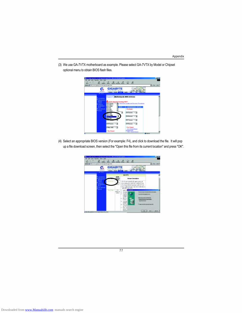
7 7
Appendix
(3) We use GA-7VTX motherboard as example. Please select GA-7VTX by Model or Chipsetoptional menu to obtain BIOS flash files.
(4) Select an appropriate BIOS version (For example: F4), and click to download the file. It will popup a file download screen, then select the "Open this file from its current location" and press "OK".
Downloaded from www.Manualslib.com manuals search engine
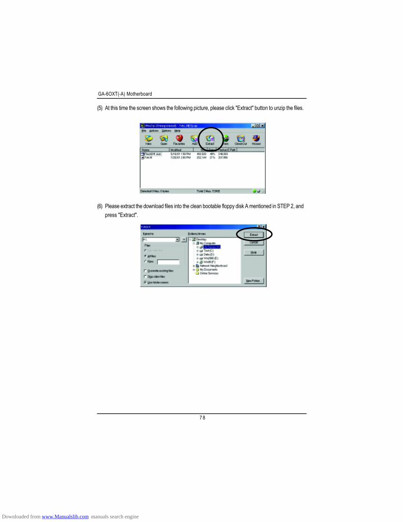
GA-6OXT(-A) Motherboard
7 8
(5) At this time the screen shows the following picture, please click "Extract" button to unzip the files.
(6) Please extract the download files into the clean bootable floppy disk A mentioned in STEP 2, andpress "Extract".
Downloaded from www.Manualslib.com manuals search engine
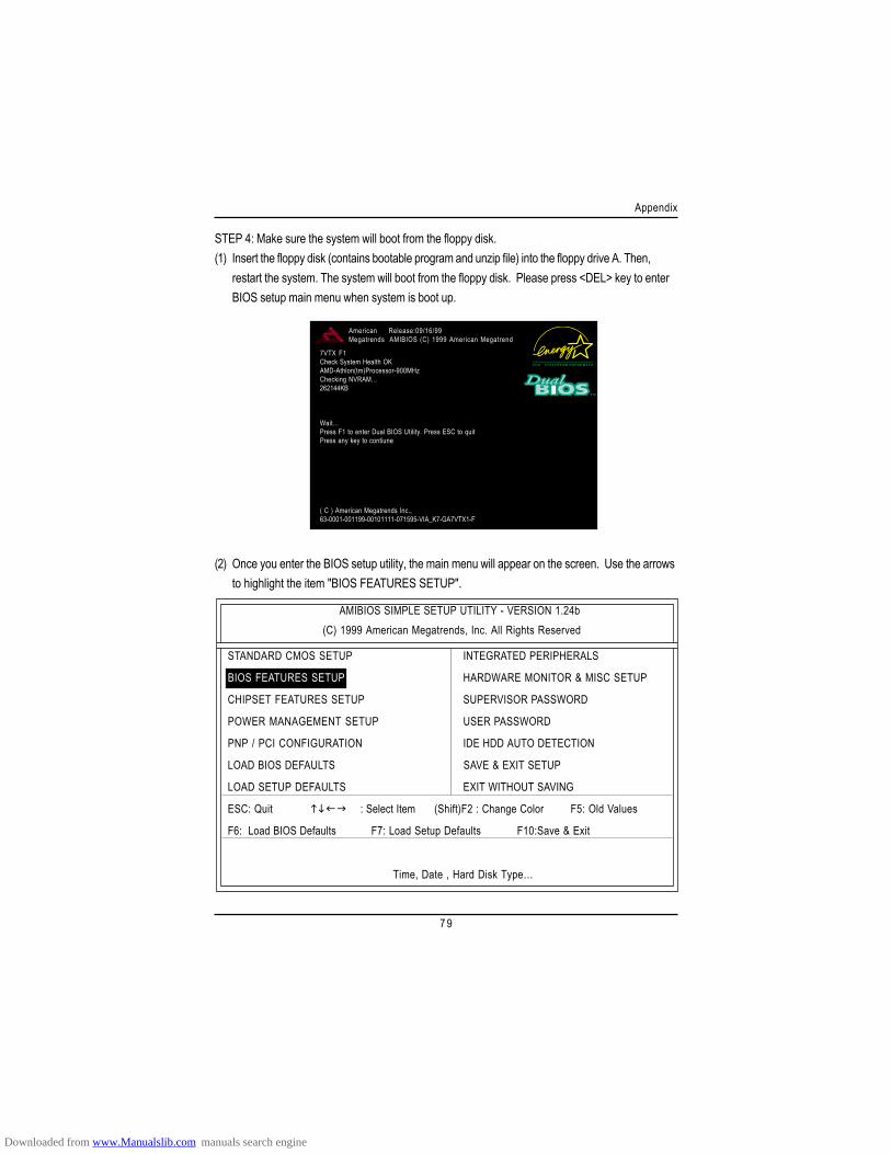
7 9
Appendix
STEP 4: Make sure the system will boot from the floppy disk.(1) Insert the floppy disk (contains bootable program and unzip file) into the floppy drive A. Then,
restart the system. The system will boot from the floppy disk. Please press <DEL> key to enterBIOS setup main menu when system is boot up.
(2) Once you enter the BIOS setup utility, the main menu will appear on the screen. Use the arrowsto highlight the item "BIOS FEATURES SETUP".
AMIBIOS SIMPLE SETUP UTILITY - VERSION 1.24b(C) 1999 American Megatrends, Inc. All Rights Reserved
STANDARD CMOS SETUP INTEGRATED PERIPHERALS
BIOS FEATURES SETUP HARDWARE MONITOR & MISC SETUP
CHIPSET FEATURES SETUP SUPERVISOR PASSWORD
POWER MANAGEMENT SETUP USER PASSWORD
PNP / PCI CONFIGURATION IDE HDD AUTO DETECTION
LOAD BIOS DEFAULTS SAVE & EXIT SETUP
LOAD SETUP DEFAULTS EXIT WITHOUT SAVING
ESC: Quit : Select Item (Shift)F2 : Change Color F5: Old Values
F6: Load BIOS Defaults F7: Load Setup Defaults F10:Save & Exit
Time, Date , Hard Disk Type…
7VTX F1Check System Health OKAMD-Athlon(tm)Processor-900MHzChecking NVRAM...262144KB
Wait...Press F1 to enter Dual BIOS Utility. Press ESC to quitPress any key to contiune
( C ) American Megatrends Inc.,63-0001-001199-00101111-071595-VIA_K7-GA7VTX1-F
American Release:09/16/99Megatrends AMIBIOS (C) 1999 American Megatrend
Downloaded from www.Manualslib.com manuals search engine
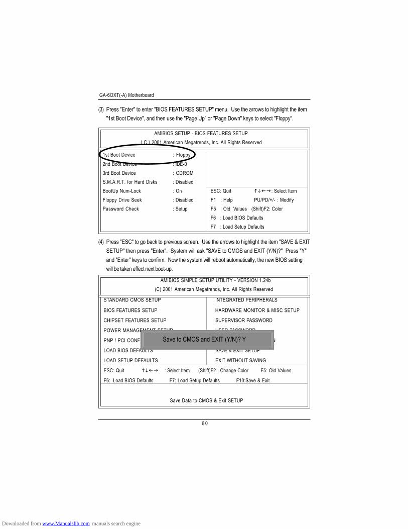
GA-6OXT(-A) Motherboard
8 0
(3) Press "Enter" to enter "BIOS FEATURES SETUP" menu. Use the arrows to highlight the item"1st Boot Device", and then use the "Page Up" or "Page Down" keys to select "Floppy".
AMIBIOS SETUP - BIOS FEATURES SETUP( C ) 2001 American Megatrends, Inc. All Rights Reserved
1st Boot Device : Floppy2nd Boot Device : IDE-03rd Boot Device : CDROMS.M.A.R.T. for Hard Disks : DisabledBootUp Num-Lock : On ESC: Quit : Select ItemFloppy Drive Seek : Disabled F1 : Help PU/PD/+/- : ModifyPassword Check : Setup F5 : Old Values (Shift)F2: Color
F6 : Load BIOS DefaultsF7 : Load Setup Defaults
(4) Press "ESC" to go back to previous screen. Use the arrows to highlight the item "SAVE & EXITSETUP" then press "Enter". System will ask "SAVE to CMOS and EXIT (Y/N)?" Press "Y"and "Enter" keys to confirm. Now the system will reboot automatically, the new BIOS settingwill be taken effect next boot-up.
AMIBIOS SIMPLE SETUP UTILITY - VERSION 1.24b(C) 2001 American Megatrends, Inc. All Rights Reserved
STANDARD CMOS SETUP INTEGRATED PERIPHERALS
BIOS FEATURES SETUP HARDWARE MONITOR & MISC SETUP
CHIPSET FEATURES SETUP SUPERVISOR PASSWORD
POWER MANAGEMENT SETUP USER PASSWORD
PNP / PCI CONFIGURATION IDE HDD AUTO DETECTION
LOAD BIOS DEFAULTS SAVE & EXIT SETUP
LOAD SETUP DEFAULTS EXIT WITHOUT SAVING
ESC: Quit : Select Item (Shift)F2 : Change Color F5: Old Values
F6: Load BIOS Defaults F7: Load Setup Defaults F10:Save & Exit
Save Data to CMOS & Exit SETUP
Save to CMOS and EXIT (Y/N)? Y
Downloaded from www.Manualslib.com manuals search engine
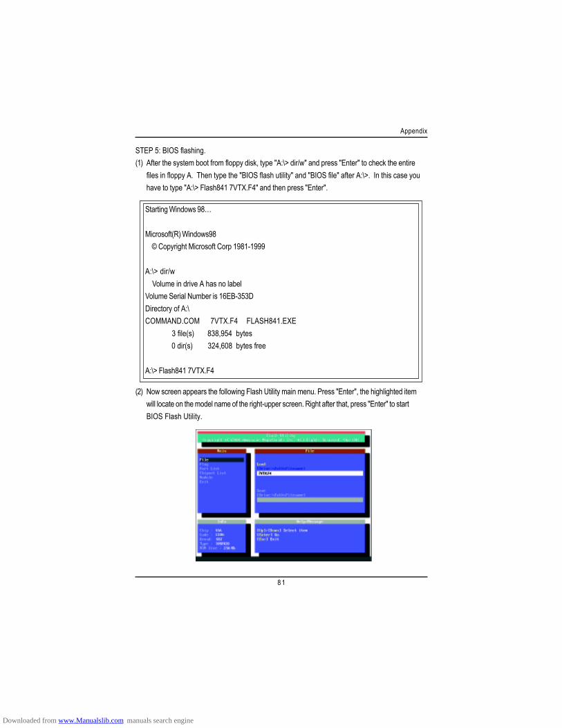
8 1
Appendix
STEP 5: BIOS flashing.(1) After the system boot from floppy disk, type "A:\> dir/w" and press "Enter" to check the entire
files in floppy A. Then type the "BIOS flash utility" and "BIOS file" after A:\>. In this case youhave to type "A:\> Flash841 7VTX.F4" and then press "Enter".
Starting Windows 98…
Microsoft(R) Windows98 © Copyright Microsoft Corp 1981-1999
A:\> dir/w Volume in drive A has no labelVolume Serial Number is 16EB-353DDirectory of A:\COMMAND.COM 7VTX.F4 FLASH841.EXE 3 file(s) 838,954 bytes 0 dir(s) 324,608 bytes free
A:\> Flash841 7VTX.F4
(2) Now screen appears the following Flash Utility main menu. Press "Enter", the highlighted itemwill locate on the model name of the right-upper screen. Right after that, press "Enter" to startBIOS Flash Utility.
Downloaded from www.Manualslib.com manuals search engine
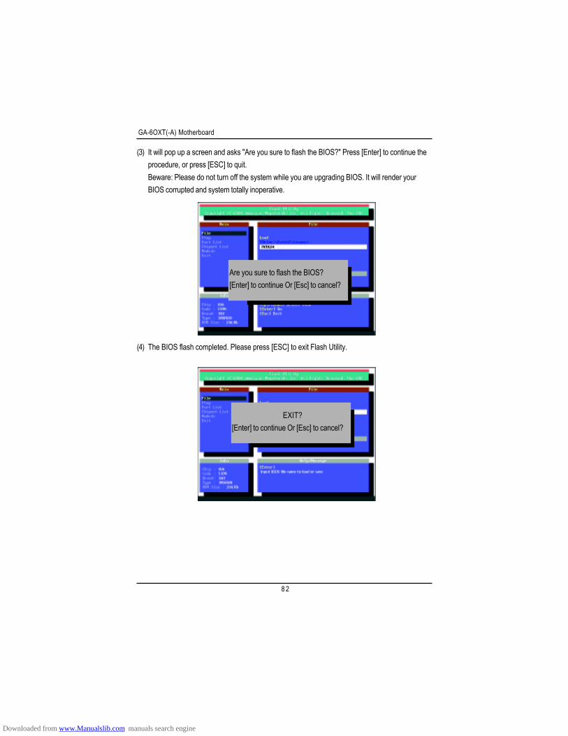
GA-6OXT(-A) Motherboard
8 2
(3) It will pop up a screen and asks "Are you sure to flash the BIOS?" Press [Enter] to continue theprocedure, or press [ESC] to quit.Beware: Please do not turn off the system while you are upgrading BIOS. It will render yourBIOS corrupted and system totally inoperative.
(4) The BIOS flash completed. Please press [ESC] to exit Flash Utility.
Are you sure to flash the BIOS?[Enter] to continue Or [Esc] to cancel?
EXIT?[Enter] to continue Or [Esc] to cancel?
Downloaded from www.Manualslib.com manuals search engine
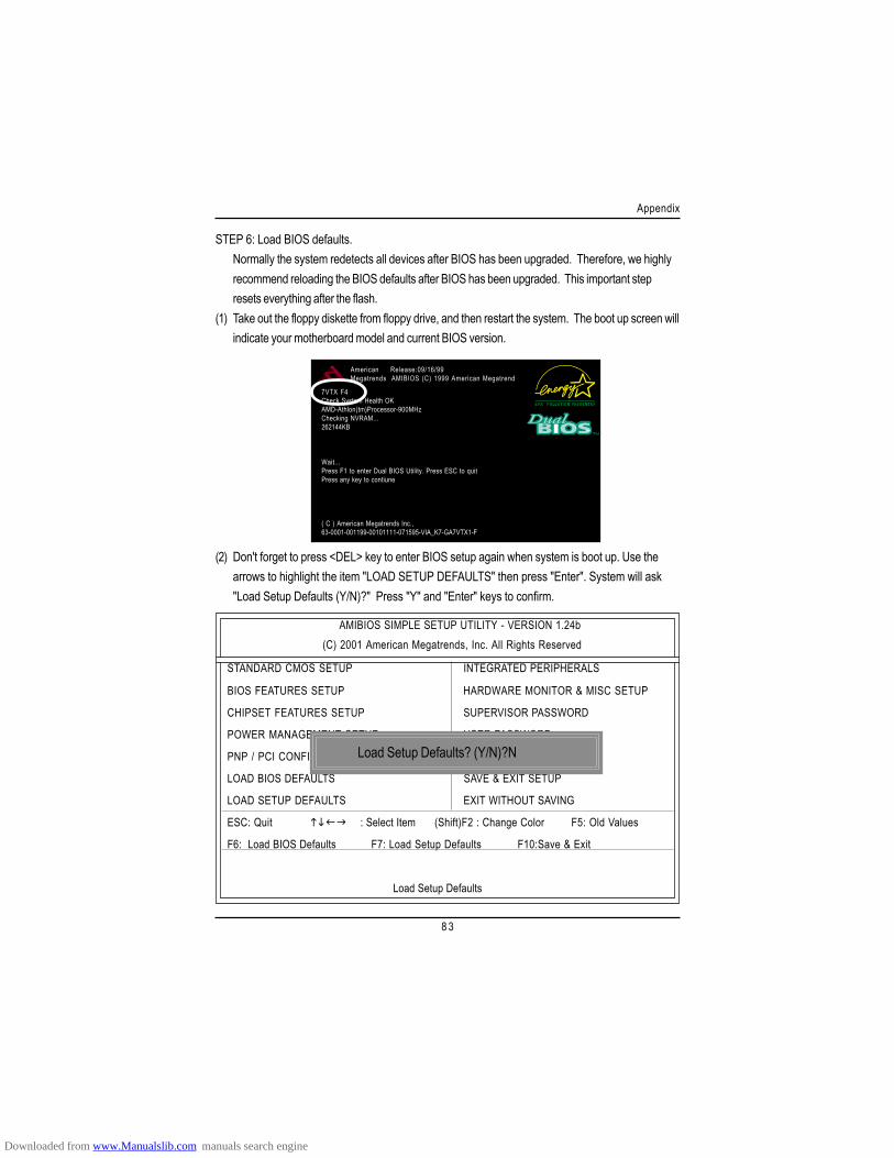
8 3
Appendix
STEP 6: Load BIOS defaults.Normally the system redetects all devices after BIOS has been upgraded. Therefore, we highlyrecommend reloading the BIOS defaults after BIOS has been upgraded. This important stepresets everything after the flash.
(1) Take out the floppy diskette from floppy drive, and then restart the system. The boot up screen willindicate your motherboard model and current BIOS version.
7VTX F4Check System Health OKAMD-Athlon(tm)Processor-900MHzChecking NVRAM...262144KB
Wait...Press F1 to enter Dual BIOS Utility. Press ESC to quitPress any key to contiune
( C ) American Megatrends Inc.,63-0001-001199-00101111-071595-VIA_K7-GA7VTX1-F
American Release:09/16/99Megatrends AMIBIOS (C) 1999 American Megatrend
(2) Don't forget to press <DEL> key to enter BIOS setup again when system is boot up. Use thearrows to highlight the item "LOAD SETUP DEFAULTS" then press "Enter". System will ask"Load Setup Defaults (Y/N)?" Press "Y" and "Enter" keys to confirm.
AMIBIOS SIMPLE SETUP UTILITY - VERSION 1.24b(C) 2001 American Megatrends, Inc. All Rights Reserved
STANDARD CMOS SETUP INTEGRATED PERIPHERALS
BIOS FEATURES SETUP HARDWARE MONITOR & MISC SETUP
CHIPSET FEATURES SETUP SUPERVISOR PASSWORD
POWER MANAGEMENT SETUP USER PASSWORD
PNP / PCI CONFIGURATION IDE HDD AUTO DETECTION
LOAD BIOS DEFAULTS SAVE & EXIT SETUP
LOAD SETUP DEFAULTS EXIT WITHOUT SAVING
ESC: Quit : Select Item (Shift)F2 : Change Color F5: Old Values
F6: Load BIOS Defaults F7: Load Setup Defaults F10:Save & Exit
Load Setup Defaults
Load Setup Defaults? (Y/N)?N
Downloaded from www.Manualslib.com manuals search engine
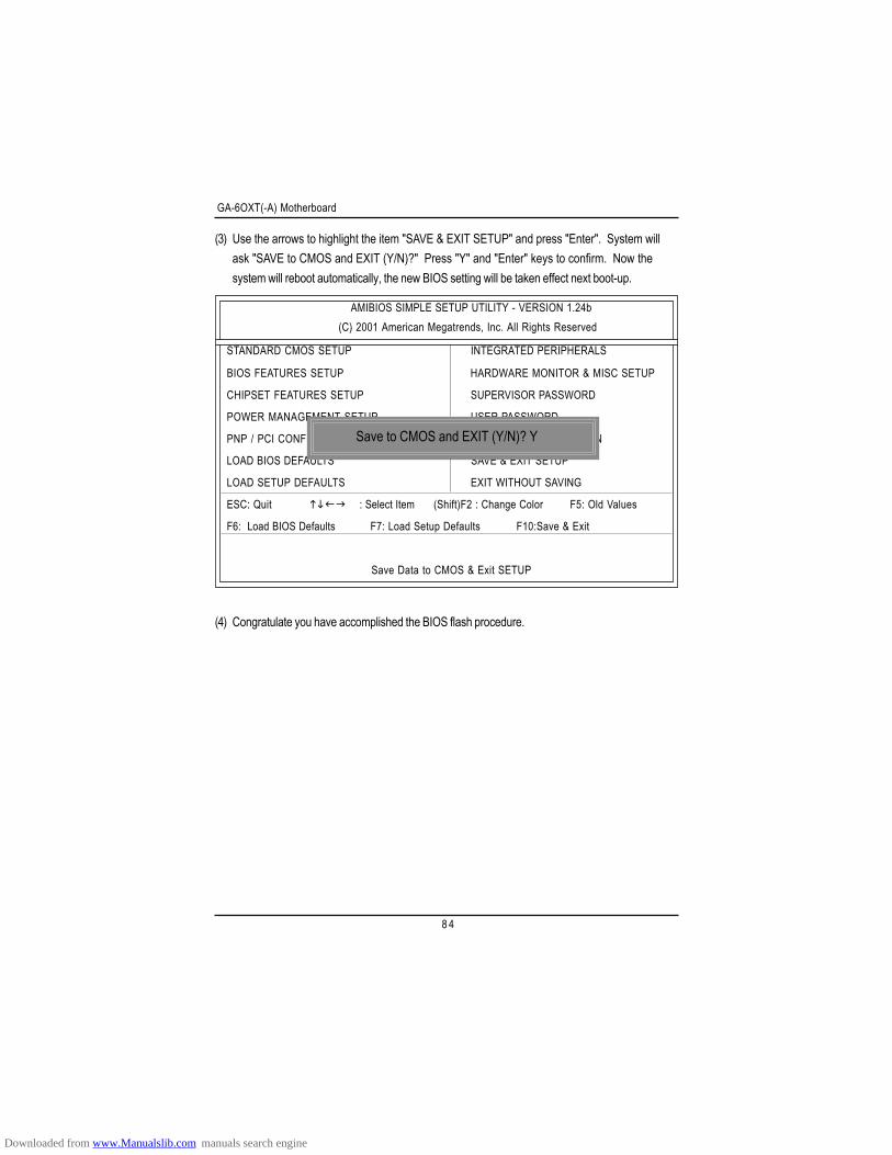
GA-6OXT(-A) Motherboard
8 4
(3) Use the arrows to highlight the item "SAVE & EXIT SETUP" and press "Enter". System willask "SAVE to CMOS and EXIT (Y/N)?" Press "Y" and "Enter" keys to confirm. Now thesystem will reboot automatically, the new BIOS setting will be taken effect next boot-up.
AMIBIOS SIMPLE SETUP UTILITY - VERSION 1.24b(C) 2001 American Megatrends, Inc. All Rights Reserved
STANDARD CMOS SETUP INTEGRATED PERIPHERALS
BIOS FEATURES SETUP HARDWARE MONITOR & MISC SETUP
CHIPSET FEATURES SETUP SUPERVISOR PASSWORD
POWER MANAGEMENT SETUP USER PASSWORD
PNP / PCI CONFIGURATION IDE HDD AUTO DETECTION
LOAD BIOS DEFAULTS SAVE & EXIT SETUP
LOAD SETUP DEFAULTS EXIT WITHOUT SAVING
ESC: Quit : Select Item (Shift)F2 : Change Color F5: Old Values
F6: Load BIOS Defaults F7: Load Setup Defaults F10:Save & Exit
Save Data to CMOS & Exit SETUP
Save to CMOS and EXIT (Y/N)? Y
(4) Congratulate you have accomplished the BIOS flash procedure.
Downloaded from www.Manualslib.com manuals search engine
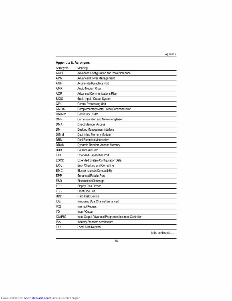
8 5
Appendix
Appendix E: AcronymsAcronyms MeaningACPI Advanced Configuration and Power InterfaceAPM Advanced Power ManagementAGP Accelerated Graphics PortAMR Audio Modem RiserACR Advanced Communications RiserBIOS Basic Input / Output SystemCPU Central Processing UnitCMOS Complementary Metal Oxide SemiconductorCRIMM Continuity RIMMCNR Communication and Networking RiserDMA Direct Memory AccessDMI Desktop Management InterfaceDIMM Dual Inline Memory ModuleDRM Dual Retention MechanismDRAM Dynamic Random Access MemoryDDR Double Data RateECP Extended Capabilities PortESCD Extended System Configuration DataECC Error Checking and CorrectingEMC Electromagnetic CompatibilityEPP Enhanced Parallel PortESD Electrostatic DischargeFDD Floppy Disk DeviceFSB Front Side BusHDD Hard Disk DeviceIDE Integrated Dual Channel EnhancedIRQ Interrupt RequestI/O Input / OutputIOAPIC Input Output Advanced Programmable Input ControllerISA Industry Standard ArchitectureLAN Local Area Network
to be continued......
Downloaded from www.Manualslib.com manuals search engine
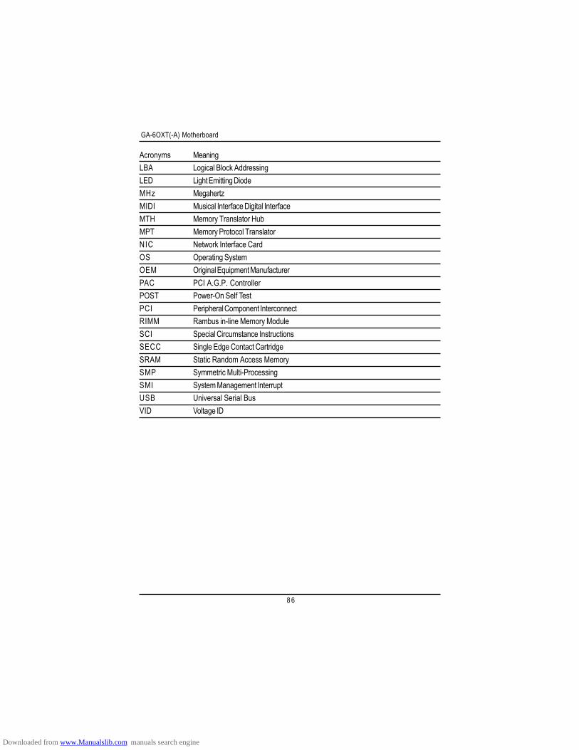
GA-6OXT(-A) Motherboard
8 6
Acronyms MeaningLBA Logical Block AddressingLED Light Emitting DiodeMHz MegahertzMIDI Musical Interface Digital InterfaceMTH Memory Translator HubMPT Memory Protocol TranslatorNIC Network Interface CardOS Operating SystemOEM Original Equipment ManufacturerPAC PCI A.G.P. ControllerPOST Power-On Self TestPCI Peripheral Component InterconnectRIMM Rambus in-line Memory ModuleSCI Special Circumstance InstructionsSECC Single Edge Contact CartridgeSRAM Static Random Access MemorySMP Symmetric Multi-ProcessingSMI System Management InterruptUSB Universal Serial BusVID Voltage ID
Downloaded from www.Manualslib.com manuals search engine
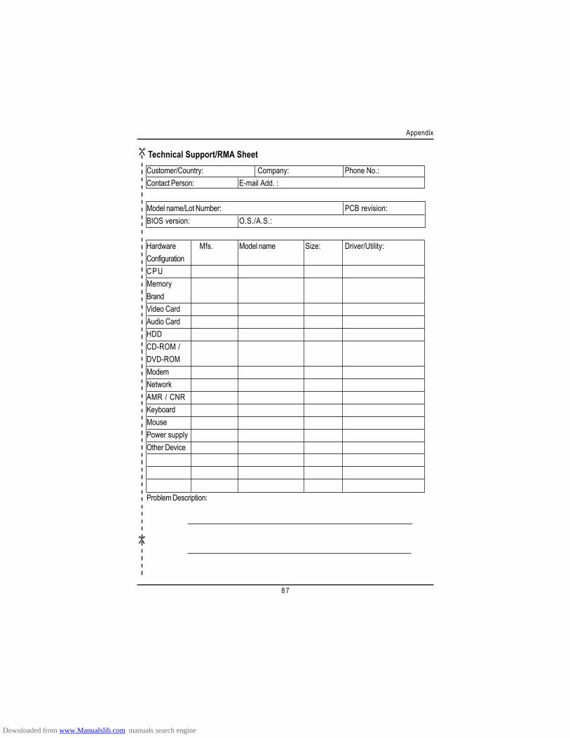
8 7
Appendix
Technical Support/RMA SheetCustomer/Country: Company: Phone No.:Contact Person: E-mail Add. :
Model name/Lot Number: PCB revision:BIOS version: O.S./A.S.:
Hardware Mfs. Model name Size: Driver/Utility:ConfigurationCPUMemoryBrandVideo CardAudio CardHDDCD-ROM /DVD-ROMModemNetworkAMR / CNRKeyboardMousePower supplyOther Device
Problem Description:
Downloaded from www.Manualslib.com manuals search engine
Related Documents