Giant magnetoresistance in melt spun Cu 85 Co 10 Ni 5 Stefano Curiotto a, , Erik Johnson b,c , Federica Celegato d , Marco Coisson d , Nini Pryds e a Dipartimento di Chimica IFM, Centro di Eccellenza NIS, Universita ` di Torino, Via P. Giuria 9,10125 Torino, Italy b Nanoscience Centre, Niels Bohr Institute, University of Copenhagen, Copenhagen, Denmark c Materials Research Department, Risoe National Laboratory, Frederiksborgvej 399, DK-4000 Roskilde, Denmark d Istituto Nazionale di Ricerca Metrologica (INRIM), strada delle Cacce 91,10135 Torino, Italy e Fuel Cell and Solid State Chemistry Department, Risoe National Laboratory, Frederiksborgvej 399, DK-4000 Roskilde, Denmark article info Article history: Received 28 November 2007 Received in revised form 19 June 2008 Available online 22 August 2008 Keywords: Cu alloy Rapid solidification GMR Magnetic property abstract CuCoNi rapidly solidified alloys are interesting because they display giant magnetoresistance (GMR). In the present work a Cu 85 Co 10 Ni 5 alloy has been synthesized by melt spinning and analysed for GMR. The ribbons obtained have been annealed at different temperatures and the evolution of the crystal structure with annealing has been studied by X-ray diffraction. The fine microstructure has been observed by TEM and related to the magnetic properties, investigated in a vibrating sample magnetometer. In the studied composition the magnetoresistance was found to be lower than in binary CuCo alloys without Ni addition. & 2008 Elsevier B.V. All rights reserved. 1. Introduction Cu–Co alloys produced by solidification from undercooled melts display giant magnetoresistance (GMR) [1]. The effect is observed when nanosized particles of ferromagnetic Co are embedded in the paramagnetic Cu matrix. In order to obtain Co precipitates, Cu-rich Cu–Co alloys must be rapidly solidified to obtain a supersaturated homogeneous solid solution. Then, the Co particles are produced in the solid state by thermal treatment, the formation occurs either by nucleation and growth [2] or by spinodal decomposition [3]. The magnetoresistance is high when the sample is constituted of many Co-rich precipitates with very small size [3]. In order to increase the number of Co-rich particles the Co percentage in the alloy could be increased. However, the Cu–Co system displays a liquid–liquid phase separation and if the alloy contains too much Co, a liquid demixing occurs during cooling, with a sharp separation between Cu-rich and Co-rich regions. After the solidification, the Co-rich particles will then be too large and the GMR of the ribbon will be diminished. The liquid phase separation can be inhibited by Ni addition, as shown in Ref. [4]. The amount of Ni necessary to the inhibition is not available from the literature. In order to improve the GMR properties, different authors studied the effect of Ni addition in Cu–Co ribbons. Kataoka et al. [5] showed that GMR can be enhanced adding Ni to Cu–Co alloys. They found a maximum magnetoresistance ratio of 7.6% in a magnetic field of 15kOe for a Cu 80 Co 15 Ni 5 rapidly solidified and annealed at 500 C. Sun et al. [6] reported that the composition Cu 82 Co 15 Ni 3 shows a GMR ratio equal to 8.6% applying a magnetic field of 13.55kOe. Wang et al. [7] investigated systematically several Cu–Co–Ni alloys prepared by melt spinning and concluded that ribbons with low-Ni content show an increase in GMR. However, in a recent work, Zhang et al. [8] studied the GMR in various Cu–Co–Ni alloys prepared by mechanical alloying and reported that the magnetoresistance ratio decreases monotonically with increasing Ni content. In the present paper a Cu 85 Co 10 Ni 5 alloy has been rapidly solidified using the melt spinning technique. Structure and microstructure of the samples have been studied by X-ray diffraction (XRD) and transmission electron microscopy and related to the magnetic and magnetoresistive properties of the ribbons. 2. Experimental details High purity copper (99.999%), cobalt (99.9%) and nickel (99.99%) have been pre-alloyed in an arc-melting furnace to obtain the composition Cu 85 Co 10 Ni 5 . Before melting, the chamber has been evacuated and purged several times with high purity Ar and using lumps of Zr as getter. Parts of the crushed ingot were inserted in a silica crucible and then melt spun onto a hardened Cu wheel under high purity Ar, obtaining ribbons about 4 mm wide and 20 mm thick. The composition of the ribbon was checked ARTICLE IN PRESS Contents lists available at ScienceDirect journal homepage: www.elsevier.com/locate/jmmm Journal of Magnetism and Magnetic Materials 0304-8853/$ - see front matter & 2008 Elsevier B.V. All rights reserved. doi:10.1016/j.jmmm.2008.08.087 Corresponding author. Present address: Centre Interdiciplinaire de Nanoscience de Marseille, CINaM-CNRS, Campus de Luminy case 913, 13288 Marseille, France. Tel.: +33 6 62922886. E-mail address: [email protected] (S. Curiotto). Journal of Magnetism and Magnetic Materials 321 (2009) 131–136

Welcome message from author
This document is posted to help you gain knowledge. Please leave a comment to let me know what you think about it! Share it to your friends and learn new things together.
Transcript
ARTICLE IN PRESS
Journal of Magnetism and Magnetic Materials 321 (2009) 131–136
Contents lists available at ScienceDirect
Journal of Magnetism and Magnetic Materials
0304-88
doi:10.1
� Corr
de Mars
Tel.: +33
E-m
journal homepage: www.elsevier.com/locate/jmmm
Giant magnetoresistance in melt spun Cu85Co10Ni5
Stefano Curiotto a,�, Erik Johnson b,c, Federica Celegato d, Marco Coisson d, Nini Pryds e
a Dipartimento di Chimica IFM, Centro di Eccellenza NIS, Universita di Torino, Via P. Giuria 9, 10125 Torino, Italyb Nanoscience Centre, Niels Bohr Institute, University of Copenhagen, Copenhagen, Denmarkc Materials Research Department, Risoe National Laboratory, Frederiksborgvej 399, DK-4000 Roskilde, Denmarkd Istituto Nazionale di Ricerca Metrologica (INRIM), strada delle Cacce 91, 10135 Torino, Italye Fuel Cell and Solid State Chemistry Department, Risoe National Laboratory, Frederiksborgvej 399, DK-4000 Roskilde, Denmark
a r t i c l e i n f o
Article history:
Received 28 November 2007
Received in revised form
19 June 2008Available online 22 August 2008
Keywords:
Cu alloy
Rapid solidification
GMR
Magnetic property
53/$ - see front matter & 2008 Elsevier B.V. A
016/j.jmmm.2008.08.087
esponding author. Present address: Centre Int
eille, CINaM-CNRS, Campus de Luminy case
6 62922886.
ail address: [email protected] (S. Curio
a b s t r a c t
CuCoNi rapidly solidified alloys are interesting because they display giant magnetoresistance (GMR). In
the present work a Cu85Co10Ni5 alloy has been synthesized by melt spinning and analysed for GMR. The
ribbons obtained have been annealed at different temperatures and the evolution of the crystal
structure with annealing has been studied by X-ray diffraction. The fine microstructure has been
observed by TEM and related to the magnetic properties, investigated in a vibrating sample
magnetometer. In the studied composition the magnetoresistance was found to be lower than in
binary CuCo alloys without Ni addition.
& 2008 Elsevier B.V. All rights reserved.
1. Introduction
Cu–Co alloys produced by solidification from undercooledmelts display giant magnetoresistance (GMR) [1]. The effect isobserved when nanosized particles of ferromagnetic Co areembedded in the paramagnetic Cu matrix. In order to obtain Coprecipitates, Cu-rich Cu–Co alloys must be rapidly solidified toobtain a supersaturated homogeneous solid solution. Then, the Coparticles are produced in the solid state by thermal treatment, theformation occurs either by nucleation and growth [2] or byspinodal decomposition [3]. The magnetoresistance is high whenthe sample is constituted of many Co-rich precipitates with verysmall size [3]. In order to increase the number of Co-rich particlesthe Co percentage in the alloy could be increased. However, theCu–Co system displays a liquid–liquid phase separation and if thealloy contains too much Co, a liquid demixing occurs duringcooling, with a sharp separation between Cu-rich and Co-richregions. After the solidification, the Co-rich particles will then betoo large and the GMR of the ribbon will be diminished. The liquidphase separation can be inhibited by Ni addition, as shown inRef. [4]. The amount of Ni necessary to the inhibition is notavailable from the literature. In order to improve the GMRproperties, different authors studied the effect of Ni addition in
ll rights reserved.
erdiciplinaire de Nanoscience
913, 13288 Marseille, France.
tto).
Cu–Co ribbons. Kataoka et al. [5] showed that GMR can beenhanced adding Ni to Cu–Co alloys. They found a maximummagnetoresistance ratio of 7.6% in a magnetic field of 15 kOe for aCu80Co15Ni5 rapidly solidified and annealed at 500 �C. Sun et al.[6] reported that the composition Cu82Co15Ni3 shows a GMR ratioequal to 8.6% applying a magnetic field of 13.55 kOe. Wang et al.[7] investigated systematically several Cu–Co–Ni alloys preparedby melt spinning and concluded that ribbons with low-Ni contentshow an increase in GMR. However, in a recent work, Zhang et al.[8] studied the GMR in various Cu–Co–Ni alloys prepared bymechanical alloying and reported that the magnetoresistanceratio decreases monotonically with increasing Ni content. In thepresent paper a Cu85Co10Ni5 alloy has been rapidly solidifiedusing the melt spinning technique. Structure and microstructureof the samples have been studied by X-ray diffraction (XRD) andtransmission electron microscopy and related to the magnetic andmagnetoresistive properties of the ribbons.
2. Experimental details
High purity copper (99.999%), cobalt (99.9%) and nickel(99.99%) have been pre-alloyed in an arc-melting furnace toobtain the composition Cu85Co10Ni5. Before melting, the chamberhas been evacuated and purged several times with high purity Arand using lumps of Zr as getter. Parts of the crushed ingot wereinserted in a silica crucible and then melt spun onto a hardenedCu wheel under high purity Ar, obtaining ribbons about 4 mmwide and 20mm thick. The composition of the ribbon was checked
ARTICLE IN PRESS
S. Curiotto et al. / Journal of Magnetism and Magnetic Materials 321 (2009) 131–136132
and confirmed using X-rays dispersive spectroscopy. Pieces of theribbon were annealed for 1 h in vacuum at different temperatures,i.e. 400, 500, 600, 700, 800 �C. They were then analysed by XRD,with a wide angle goniometer in the Bragg–Brentano configura-tion, employing CuKa radiation. The goniometer was operated in astep-scanning mode acquiring data every 0:03� for some tens ofseconds at every step. The XRD patterns were analysed by meansof the Rietveld refinement method [9] employing the MAUDsoftware [10]. The ribbons were then inserted in a vibratingsample magnetometer (VSM). A magnetic field ranging from �16to 16 kOe was applied in the instrument and the correspondingmagnetization of the samples was measured. The change inelectrical resistivity as a function of the applied magnetic field(attributed to the GMR effect) was measured using a dc fourcontacts geometry. The contacts were glued to the samples withan Ag paste. GMR is defined as dR=R ¼ ½RðHÞ � RðH0Þ�=RðH0Þ. Thefield was applied both parallel and perpendicular to the ribbonsurface. All the measurements were performed at room tempera-ture. The ribbons were subsequently thinned by electro-polishingto be observed by TEM using a Jeol 3000F operated at anaccelerating voltage of 300 kV.
3. Results and discussion
3.1. X-ray diffraction
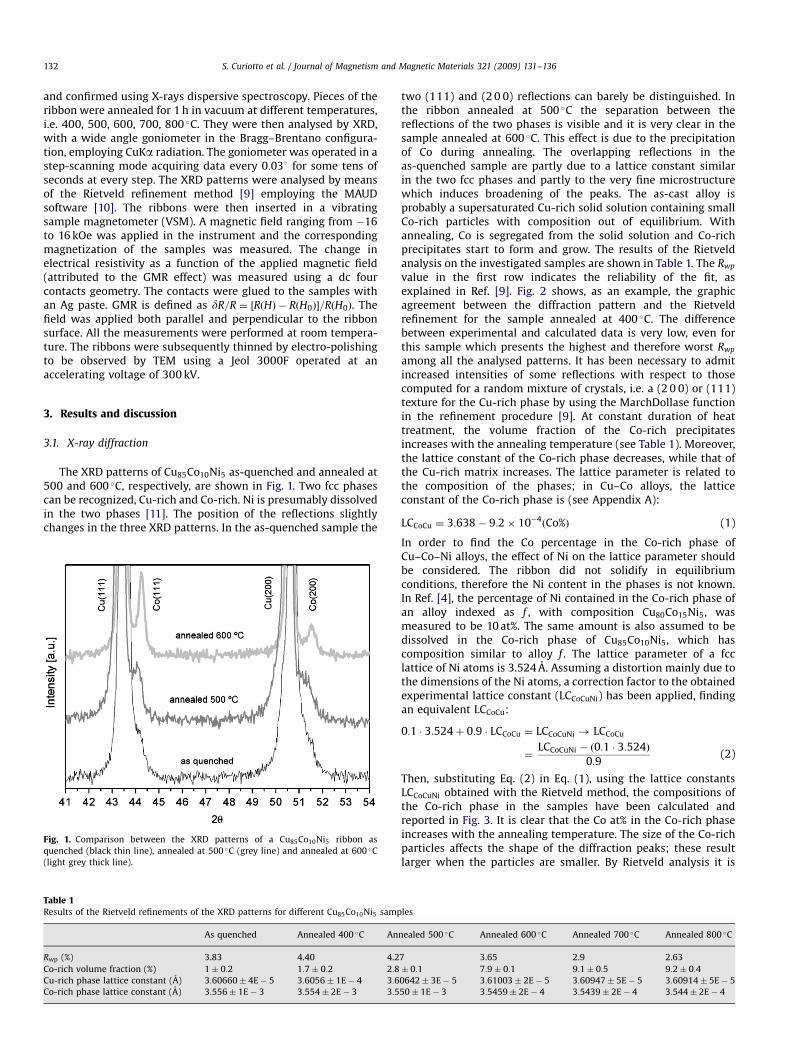
The XRD patterns of Cu85Co10Ni5 as-quenched and annealed at500 and 600 �C, respectively, are shown in Fig. 1. Two fcc phasescan be recognized, Cu-rich and Co-rich. Ni is presumably dissolvedin the two phases [11]. The position of the reflections slightlychanges in the three XRD patterns. In the as-quenched sample the
Fig. 1. Comparison between the XRD patterns of a Cu85Co10Ni5 ribbon as
quenched (black thin line), annealed at 500 �C (grey line) and annealed at 600 �C
(light grey thick line).
Table 1
Results of the Rietveld refinements of the XRD patterns for different Cu85Co10Ni5 samp
As quenched Annealed 400 �C An
Rwp (%) 3.83 4.40 4.2
Co-rich volume fraction (%) 1� 0:2 1:7� 0:2 2:8
Cu-rich phase lattice constant (A) 3:60660� 4E� 5 3:6056� 1E� 4 3:6
Co-rich phase lattice constant (A) 3:556� 1E� 3 3:554� 2E� 3 3:5
two (111) and (2 0 0) reflections can barely be distinguished. Inthe ribbon annealed at 500 �C the separation between thereflections of the two phases is visible and it is very clear in thesample annealed at 600 �C. This effect is due to the precipitationof Co during annealing. The overlapping reflections in theas-quenched sample are partly due to a lattice constant similarin the two fcc phases and partly to the very fine microstructurewhich induces broadening of the peaks. The as-cast alloy isprobably a supersaturated Cu-rich solid solution containing smallCo-rich particles with composition out of equilibrium. Withannealing, Co is segregated from the solid solution and Co-richprecipitates start to form and grow. The results of the Rietveldanalysis on the investigated samples are shown in Table 1. The Rwp
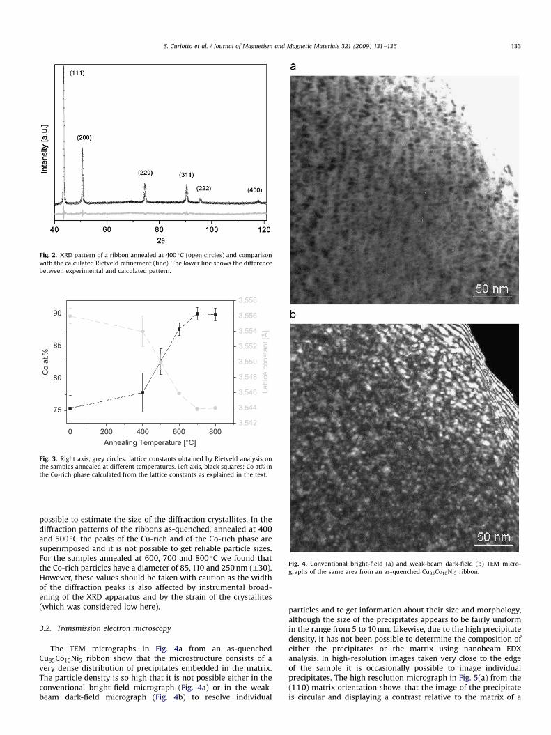
value in the first row indicates the reliability of the fit, asexplained in Ref. [9]. Fig. 2 shows, as an example, the graphicagreement between the diffraction pattern and the Rietveldrefinement for the sample annealed at 400 �C. The differencebetween experimental and calculated data is very low, even forthis sample which presents the highest and therefore worst Rwp
among all the analysed patterns. It has been necessary to admitincreased intensities of some reflections with respect to thosecomputed for a random mixture of crystals, i.e. a (2 0 0) or (111)texture for the Cu-rich phase by using the MarchDollase functionin the refinement procedure [9]. At constant duration of heattreatment, the volume fraction of the Co-rich precipitatesincreases with the annealing temperature (see Table 1). Moreover,the lattice constant of the Co-rich phase decreases, while that ofthe Cu-rich matrix increases. The lattice parameter is related tothe composition of the phases; in Cu–Co alloys, the latticeconstant of the Co-rich phase is (see Appendix A):
LCCoCu ¼ 3:638� 9:2� 10�4ðCo%Þ (1)
In order to find the Co percentage in the Co-rich phase ofCu–Co–Ni alloys, the effect of Ni on the lattice parameter shouldbe considered. The ribbon did not solidify in equilibriumconditions, therefore the Ni content in the phases is not known.In Ref. [4], the percentage of Ni contained in the Co-rich phase ofan alloy indexed as f , with composition Cu80Co15Ni5, wasmeasured to be 10 at%. The same amount is also assumed to bedissolved in the Co-rich phase of Cu85Co10Ni5, which hascomposition similar to alloy f . The lattice parameter of a fcclattice of Ni atoms is 3.524 A. Assuming a distortion mainly due tothe dimensions of the Ni atoms, a correction factor to the obtainedexperimental lattice constant (LCCoCuNi) has been applied, findingan equivalent LCCoCu:
0:1 � 3:524þ 0:9 � LCCoCu ¼ LCCoCuNi ! LCCoCu
¼LCCoCuNi � ð0:1 � 3:524Þ
0:9(2)
Then, substituting Eq. (2) in Eq. (1), using the lattice constantsLCCoCuNi obtained with the Rietveld method, the compositions ofthe Co-rich phase in the samples have been calculated andreported in Fig. 3. It is clear that the Co at% in the Co-rich phaseincreases with the annealing temperature. The size of the Co-richparticles affects the shape of the diffraction peaks; these resultlarger when the particles are smaller. By Rietveld analysis it is
les
nealed 500 �C Annealed 600 �C Annealed 700 �C Annealed 800 �C
7 3.65 2.9 2.63
� 0:1 7:9� 0:1 9:1� 0:5 9:2� 0:4
0642� 3E� 5 3:61003� 2E� 5 3:60947� 5E� 5 3:60914� 5E� 5
50� 1E� 3 3:5459� 2E� 4 3:5439� 2E� 4 3:544� 2E� 4
ARTICLE IN PRESS
Fig. 2. XRD pattern of a ribbon annealed at 400 �C (open circles) and comparison
with the calculated Rietveld refinement (line). The lower line shows the difference
between experimental and calculated pattern.
3.548
3.550
3.552
3.554
3.556
3.546
3.544
3.542
Latti
ce c
onst
ant [
Å]
90
85
80
75
0 200 400 600 800Annealing Temperature [°C]
Co
at.%
3.558
Fig. 3. Right axis, grey circles: lattice constants obtained by Rietveld analysis on
the samples annealed at different temperatures. Left axis, black squares: Co at% in
the Co-rich phase calculated from the lattice constants as explained in the text.
Fig. 4. Conventional bright-field (a) and weak-beam dark-field (b) TEM micro-
graphs of the same area from an as-quenched Cu85Co10Ni5 ribbon.
S. Curiotto et al. / Journal of Magnetism and Magnetic Materials 321 (2009) 131–136 133
possible to estimate the size of the diffraction crystallites. In thediffraction patterns of the ribbons as-quenched, annealed at 400and 500 �C the peaks of the Cu-rich and of the Co-rich phase aresuperimposed and it is not possible to get reliable particle sizes.For the samples annealed at 600, 700 and 800 �C we found thatthe Co-rich particles have a diameter of 85, 110 and 250 nm (�30).However, these values should be taken with caution as the widthof the diffraction peaks is also affected by instrumental broad-ening of the XRD apparatus and by the strain of the crystallites(which was considered low here).
3.2. Transmission electron microscopy
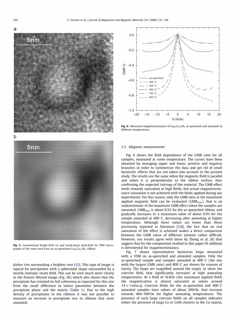
The TEM micrographs in Fig. 4a from an as-quenchedCu85Co10Ni5 ribbon show that the microstructure consists of avery dense distribution of precipitates embedded in the matrix.The particle density is so high that it is not possible either in theconventional bright-field micrograph (Fig. 4a) or in the weak-beam dark-field micrograph (Fig. 4b) to resolve individual
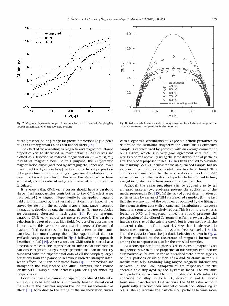
particles and to get information about their size and morphology,although the size of the precipitates appears to be fairly uniformin the range from 5 to 10 nm. Likewise, due to the high precipitatedensity, it has not been possible to determine the composition ofeither the precipitates or the matrix using nanobeam EDXanalysis. In high-resolution images taken very close to the edgeof the sample it is occasionally possible to image individualprecipitates. The high resolution micrograph in Fig. 5(a) from the(110) matrix orientation shows that the image of the precipitateis circular and displaying a contrast relative to the matrix of a
ARTICLE IN PRESS
Fig. 5. Conventional bright-field (a) and weak-beam dark-field (b) TEM micro-
graphs of the same area from an as-quenched Cu85Co10Ni5 ribbon.
as-quenched400 °C500 °C600 °C700 °C800 °C
GM
R %
0.0
–0.2
–0.4
–0.6
–0.8
–1.0–20 –15 –10 –5 0 5 10 15 20
H (kOe)
Fig. 6. Measured magnetoresistance of Cu85Co10Ni5 as quenched and annealed at
different temperatures.
S. Curiotto et al. / Journal of Magnetism and Magnetic Materials 321 (2009) 131–136134
darker rim surrounding a brighter core [12]. This type of image istypical for precipitates with a spheroidal shape surrounded by amostly isotropic strain field. This can be seen much more clearlyin the Fourier filtered image (Fig. 5b) which also shows that theprecipitate has retained its full coherency as expected for this sizefrom the small difference in lattice parameter between theprecipitate phase and the matrix (Table 1). Due to the highdensity of precipitates in the ribbons it was not possible tomeasure an increase in precipitate size in ribbons that wereannealed.
3.3. Magnetic measurements
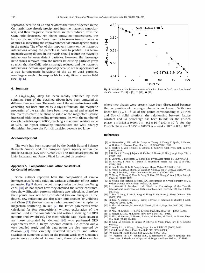
Fig. 6 shows the field dependence of the GMR ratio for allsamples, measured at room temperature. The curves have beenobtained by averaging upper and lower, positive and negativebranches in order to symmetrize the data and get rid of smallhysteretic effects that are not taken into account in the presentstudy. The results are the same when the magnetic field is paralleland when it is perpendicular to the ribbon surface, thusconfirming the expected isotropy of the material. The GMR effecttends towards saturation at high fields, but actual magnetoresis-tance saturation is not achieved with the fields applied during ourexperiments. For this reason, only the GMR ratio at the maximumapplied magnetic field can be evaluated (GMRmax), that is anunderestimate of the maximum GMR effect when the samples aresaturated. GMRmax is about 0.5% for the as-quenched ribbon, andgradually increases to a maximum value of about 0.9% for thesample annealed at 400 �C, decreasing after annealing at highertemperature. Although these values are lower than thosepreviously reported in literature [5,8], the fact that no realsaturation of the effect is achieved makes a direct comparisonbetween the GMR ratios of different systems rather difficult.However, our results agree with those by Zhang et al. [8] thatsuggest that for the composition studied in this paper Ni additionis detrimental for magnetoresistance.
Fig. 7 shows representative hysteresis loops measuredwith a VSM on as-quenched and annealed samples. Only theas-quenched sample and samples annealed at 400 �C (the onewith the largest GMR ratio) and 800 �C are shown for reasons ofclarity. The loops are magnified around the origin, to show thecoercive field, that significantly increases at high annealingtemperatures. At a field of 16 kOe (the maximum applied field)the magnetization is almost saturated at values around14� 1 emu=g. Coercive fields for the as-quenched and 400 �Cannealed samples have values of about 200 Oe, that increasetowards 400–500 Oe for higher annealing temperatures. Thepresence of such large coercive fields on all samples indicateseither the presence of large Co or CoNi clusters in the Cu matrix,
ARTICLE IN PRESS
Fig. 7. Magnetic hysteresis loops of as-quenched and annealed Cu85Co10Ni5
ribbons (magnification of the low field region).
–1.0 0.00.0
0.2
0.4
0.6
0.8
1.0
M / MS
GM
Rre
d
as quenched400 °C500 °C600 °C700 °C800 °Cnon interacting particles
–0.5 0.5 1.0
Fig. 8. Reduced GMR ratio vs. reduced magnetization for all studied samples; the
case of non-interacting particles is also reported.
S. Curiotto et al. / Journal of Magnetism and Magnetic Materials 321 (2009) 131–136 135
or the presence of long-range magnetic interactions (e.g. dipolaror RKKY) among small Co or CoNi nanoclusters [13].
The effect of the annealing on magnetic and magnetoresistanceproperties can be discussed in more detail if GMR curves areplotted as a function of reduced magnetization (m ¼ MðHÞ=MS)instead of magnetic field. To this purpose, the anhystereticmagnetization curve (obtained by averaging the upper and lowerbranches of the hysteresis loop) has been fitted by a superpositionof Langevin functions representing a lognormal distribution of theradii of spherical particles. In this way, the MS value has beenestimated, and the reduced anhysteretic magnetization m can becalculated.
It is known that GMR vs. m curves should have a parabolicshape if all nanoparticles contributing to the GMR effect wereuncorrelated (i.e. aligned independently by the applied magneticfield and misaligned by the thermal agitation); the shapes of thecurves deviate from the parabolic shape if long-range magneticinteractions develop among the nanoparticles; flat-top parabolasare commonly observed in such cases [14]. For our systems,parabolic GMR vs. m curves are never observed. The parabolicbehaviour is reported only at high fields (values of m approaching1) because in this case the magnetostatic energy of the appliedmagnetic field overcomes the interaction energy of the nano-particles, thus uncorrelating them. The experimental data onavailable samples are reported in Fig. 8 following the approachdescribed in Ref. [14], where a reduced GMR ratio is plotted as afunction of m; with this representation, the case of uncorrelatedparticles is represented by a single parabola that can be directlycompared with the experimental data of all the samples; largerdeviations from the parabolic behaviour indicate stronger inter-action effects. As it can be noticed from Fig. 8, interactions arestronger in the as-quenched and 400 �C samples, then reducefor the 500 �C sample, then increase again for higher annealingtemperatures.
Deviations from the parabolic shape of the reduced GMR ratiovs. m can also be ascribed to a sufficiently broad distribution ofthe radii of the particles responsible for the magnetoresistiveeffect [15]. According to the fitting of the magnetization curves
with a lognormal distribution of Langevin functions performed todetermine the saturation magnetization value, the as-quenchedsample is characterized by particles with an average diameter of6:2� 1:4 nm, which is in very good agreement with the TEMresults reported above. By using the same distribution of particlessize, the model proposed in Ref. [15] has been applied to calculatethe resulting GMR vs. H curve for the as-quenched sample, but noagreement with the experimental data has been found. Thisenforces our conclusion that the observed deviation of the GMRvs. m curves from the parabolic shape has to be ascribed to longranged magnetic interactions among the nanoparticles.
Although the same procedure can be applied also to allannealed samples, two problems prevent the application of themodel proposed in Ref. [15]: (a) the lack of direct determination ofparticles size by means of TEM on annealed samples; (b) the factthat the average radii of the particles, as obtained by the fitting ofthe magnetization data with a lognormal distribution of Langevinfunctions, seem to progressively reduce. This is contrary to what isfound by XRD and expected (annealing should promote theprecipitation of the diluted Co atoms that form new particles andincrease the size of the existing ones), but is consistent with theapparent reduction of the particles size that is observed ininteracting superparamagnetic systems (see e.g. Refs. [16,17]).Thus the deviation from the parabolic behaviour shown in Fig. 8,is here attributed to the occurrence of magnetic interactionsamong the nanoparticles also for the annealed samples.
As a consequence of the previous discussions of magnetic andmagnetoresistive data, the properties of our samples can then besummarized as follows: in the as-quenched state, either large Coor CoNi particles or dissolution of Co and Ni atoms in the Cumatrix that help sustaining long-ranged magnetic interactionsbetween Co and CoNi nanoparticles are responsible for thecoercive field displayed by the hysteresis loops. The availablenanoparticles are responsible for the observed GMR ratio. Onannealing the alloy up to 400 �C, diluted Co and Ni atomsform new nanoclusters that increase the GMR ratio withoutsignificantly affecting their magnetic correlation. Annealing at500 �C should increase the particle size; particles become more
ARTICLE IN PRESS
S. Curiotto et al. / Journal of Magnetism and Magnetic Materials 321 (2009) 131–136136
separated, because all Co and Ni atoms that were dispersed in theCu matrix have already precipitated into the magnetic nanoclus-ters, and their magnetic interactions are thus reduced. Thus theGMR ratio decreases. For higher annealing temperatures, thelattice constant of the Cu-rich matrix increases toward the valueof pure Cu, indicating the impoverishment of ferromagnetic atomsin the matrix. The effect of this impoverishment on the magneticinteractions among the particles is hard to predict. Less ferro-magnetic atoms diluted in the matrix should reduce the magneticinteractions between distant particles. However, the ferromag-netic atoms removed from the matrix let existing particles growso much that the GMR ratio is strongly reduced, and the magneticinteractions increase again probably because of the appearance ofa true ferromagnetic behaviour of the Co or CoNi particles,now large enough to be responsible for a significant coercive field(see Fig. 6).
Fig. 9. Variation of the lattice constant of the fcc phase in Cu–Co as a function of
the Co content. , [18]; � [2]; & [19]; ’ [20].
4. Summary
A Cu85Co10Ni5 alloy has been rapidly solidified by meltspinning. Parts of the obtained ribbon have been annealed atdifferent temperatures. The evolution of the microstructures withannealing has been studied by X-rays diffraction. The magneticproperties of the samples have been investigated and related tothe microstructure; the absolute value of the magnetoresistanceincreased with the annealing temperature, i.e. with the number ofCo-rich particles, up to 400 �C, reaching a maximum relative valueof 0.9%. For higher annealing temperatures the GMR sharplydiminishes, because the Co-rich particles become too large.
Acknowledgement
The work has been supported by the Danish Natural ScienceResearch Council and the European Space Agency within theproject CoolCop (ESA-MAP AO 99-010). The authors are grateful toLivio Battezzati and Franco Vinai for helpful discussions.
Appendix A. Compositions and lattice constants ofCu–Co solid solutions
Some authors reported how the composition of Cu–Cohomogeneous fcc solid solutions varies as a function of the latticeparameter. Fig. 9 shows the points reported in the literature. Wanget al. [18] do not report how they obtained the lattice constants,they show diffraction patterns with only two reflections, thereforetheir points have not been considered (hollow triangles in thefigure). Few reflections are also taken into account by Childressand Chien [19] (hollow squares) who prepared their samples bymagnetron sputtering. In Ref. [2] the lattice parameters werecalculated for few compositions, without explanation of themethod used in the computation and without showing the XRDpatterns (hollow circles). The most reliable data (black squares)are those calculated by Klement [20] who performed XRDexperiments with a Debye–Scherrer camera. He carried out avery detailed study and his data points are also reported byPearson [21] who carefully reviewed structures and latticespacings in numerous alloys. In the present work, only Klement’spoints were considered. Among them, those related to samples
where two phases were present have been disregarded becausethe composition of the single phases is not known. With twolinear fits (y ¼ aþ b � x) of the points corresponding to Cu-richand Co-rich solid solutions, the relationship between latticeconstant and Co percentage has been found; for the Co-richphase a ¼ 3:638� 0:004; b ¼ �9:2� 10�4
� 0:4� 10�4; for theCu-rich phase a ¼ 3:6156� 0:0003, b ¼ �4:4� 10�4
� 0:3� 10�4.
References
[1] A. Berkowitz, J. Mitchell, M. Carey, A. Young, S. Zhang, F. Spada, F. Parker,A. Hutten, G. Thomas, Phys. Rev. Lett. 68 (25) (1992) 3745.
[2] J. Wecker, R. von Helmolt, L. Schultz, K. Samwer, Appl. Phys. Lett. 62 (16)(1993) 1985.
[3] R.H. Yu, X.X. Zhang, J. Tejada, M. Knobel, P. Tiberto, P. Allia, J. Appl. Phys. 78 (1)(1995) 392.
[4] S. Curiotto, L. Battezzati, E. Johnson, N. Pryds, Acta Mater. 55 (2007) 6642.[5] N. Kataoka, I. Kim, H. Takeda, K. Fukamichi, Mater. Sci. Eng. A 181/182
(1994) 888.[6] Z. Sun, X. Zhu, X. Li, X. Song, J. Magn. Magn. Mater. 269 (2004) 341.[7] F. Wang, T. Zhao, Z. Zhang, M. Wang, D. Xiong, X. Jin, D. Geng, X. Zhao, W. Liu,
M. Yu, F. De Boer, J. Phys. Condensed Matter 12 (2000) 2525.[8] Y. Zhang, Z. Zhang, Q. Xiao, D. Geng, X. Zhao, W. Zhang, C. You, J. Phys. D Appl.
Phys. 36 (2003) 1159.[9] R. Young, The Rietveld Method, IUC Monographs on Crystallography, vol. 5,
Oxford Science Publications, Oxford, UK, 1995.[10] L. Lutterotti, S. Matthies, H.-R. Wenk, in: Proceedings of the Twelfth
International Conference on Textures of Materials (ICOTOM-12), vol. 1, 1999,pp. 1599.
[11] Z. Sun, X. Song, Z. Hu, S. Yang, G. Liang, R. Cochrane, J. Alloys Compds. 319(2001) 276.
[12] X. Liao, A. Serquis, Y. Zhu, J. Huang, L. Civale, D. Peterson, F. Mueller, J. Appl.Phys. 93 (2003) 6208.
[13] P. Allia, M. Coisson, M. Knobel, P. Tiberto, F. Vinai, Phys. Rev. B 60 (17) (1999)12207.
[14] P. Allia, M. Knobel, P. Tiberto, F. Vinai, Phys. Rev. B 52 (21) (1995) 15398.[15] E. Ferrari, F. Silva, M. Knobel, Phys. Rev. B 56 (1997) 6086.[16] P. Allia, M. Coisson, P. Tiberto, F. Vinai, M. Knobel, M. Novak, W. Nunes, Phys.
Rev. B 64 (2001) 144420.[17] P. Allia, M. Coisson, P. Spizzo, P. Tiberto, F. Vinai, Phys. Rev. B 73 (2006)
054409.[18] T. Wang, F. Li, Y. Wang, L. Song, Phys. Status Solidi 203 (2006) 2426.[19] J. Childress, C. Chien, Phys. Rev. B 43 (10) (1991) 8089.[20] W. Klement, Trans. Metall. Soc. AIME 227 (1963) 965.[21] W. Pearson, in: G.V. Raynor (Ed.), A Handbook of Lattice Spacings and
Structures of Metals and Alloys, vol. 4, Pergamon Press, Oxford, UK, 1964.
Related Documents