TFT-LCD MONITOR GH17LS GH17ES Manual SERVICE TFT-LCD MONITOR CONTENTS 1. Precautions 2. Product Specifications 3. Disassembly & Reassembly 4. Alignments & Adjustments 5. Troubleshooting 6. Exploded View & Parts List 7. Electrical Parts List 8. Block Diagram 9. Wiring Diagram 10. Schematic Diagrams 11. Panel Description

Welcome message from author
This document is posted to help you gain knowledge. Please leave a comment to let me know what you think about it! Share it to your friends and learn new things together.
Transcript

TFT-LCD MONITORGH17LSGH17ES
ManualSERVICETFT-LCD MONITOR CONTENTS
1. Precautions
2. Product Specifications
3. Disassembly & Reassembly
4. Alignments & Adjustments
5. Troubleshooting
6. Exploded View & Parts List
7. Electrical Parts List
8. Block Diagram
9. Wiring Diagram
10. Schematic Diagrams
11. Panel Description

GH17LS/GH17ES 1-1
1-1-1 Warnings1. For continued safety, do not attempt to modify the
circuit board.
2. Disconnect the AC power and DC power jackbefore servicing.
1-1-2 Servicing the LCD Monitor1. When servicing the LCD Monitor, Disconnect the
AC line cord from the AC outlet.
2. It is essential that service technicians have anaccurate voltage meter available at all times. Checkthe calibration of this meter periodically.
1-1-3 Fire and Shock HazardBefore returning the monitor to the user, perform thefollowing safety checks:
1. Inspect each lead dress to make certain that theleads are not pinched or that hardware is notlodged between the chassis and other metal parts inthe monitor.
2. Inspect all protective devices such as nonmetalliccontrol knobs, insulating materials, cabinet backs,adjustment and compartment covers or shields,isolation resistor-capacitor networks, mechanicalinsulators, etc.
3. Leakage Current Hot Check (Figure 1-1):
WARNING:
Do not use an isolation transformer during this test.Use a leakage current tester or a metering systemthat complies with American National StandardsInstitute (ANSI C101.1, Leakage Current forAppliances), and Underwriters Laboratories (ULPublication UL1410, 59.7).
Figure 1-1. Leakage Current Test Circuit
4. With the unit completely reassembled, plug the ACline cord directly into a 120V AC outlet. With theunit’s AC switch first in the ON position and thenOFF, measure the current between a known earthground (metal water pipe, conduit, etc.) and allexposed metal parts, including: metal cabinets,screwheads and control shafts. The currentmeasured should not exceed 0.5 milliamp. Reversethe power-plug prongs in the AC outlet and repeatthe test.
1-1-4 Product Safety NoticesSome electrical and mechanical parts have specialsafety-related characteristics which are often notevident from visual inspection. The protection they givemay not be obtained by replacing them withcomponents rated for higher voltage, wattage, etc. Partsthat have special safety characteristics are identified by
on schematics and parts lists. A substitutereplacement that does not have the same safetycharacteristics as the recommended replacement partmight create shock, fire and / or other hazards. Productsafety is under review continuously and newinstructions are issued whenever appropriate.
1 PrecautionsFollow these safety, servicing and ESD precautions to prevent damage and to protect against potential hazards such aselectrical shock.
1-1 Safety Precautions
DEVICEUNDERTEST
TEST ALLEXPOSED METAL
SURFACES
(READING SHOULDNOT BE ABOVE 0.5mA)
LEAKAGECURRENTTESTER
2-WIRE CORD
*ALSO TEST WITHPLUG REVERSED
(USING AC ADAPTERPLUG AS REQUIRED) EARTH
GROUND
!

1-2-1 General Servicing Precautions1. Always unplug the unit’s AC power cord from the
AC power source and disconnect the DC PowerJack before attempting to:(a) remove or reinstall any component or assembly,(b) disconnect PCB plugs or connectors, (c) connecta test component in parallel with an electrolyticcapacitor.
2. Some components are raised above the printedcircuit board for safety. An insulation tube or tapeis sometimes used. The internal wiring issometimes clamped to prevent contact withthermally hot components. Reinstall all suchelements to their original position.
3. After servicing, always check that the screws,components and wiring have been correctlyreinstalled. Make sure that the area around theserviced part has not been damaged.
1. Immediately before handling any semiconductorcomponents or assemblies, drain the electrostaticcharge from your body by touching a known earthground. Alternatively, wear a discharging wrist-strap device. To avoid a shock hazard, be sure toremove the wrist strap before applying power tothe monitor.
2. After removing an ESD-equipped assembly, place iton a conductive surface such as aluminum foil toprevent accumulation of an electrostatic charge.
3. Do not use freon-propelled chemicals. These cangenerate electrical charges sufficient to damageESDs.
4. Use only a grounded-tip soldering iron to solder ordesolder ESDs.
5. Use only an anti-static solder removal device. Somesolder removal devices not classified as “anti-static”can generate electrical charges sufficient to damageESDs.
4. Check the insulation between the blades of the ACplug and accessible conductive parts (examples:metal panels, input terminals and earphone jacks).
5. Insulation Checking Procedure: Disconnect thepower cord from the AC source and turn the powerswitch ON. Connect an insulation resistance meter(500 V) to the blades of the AC plug.
The insulation resistance between each blade of theAC plug and accessible conductive parts (seeabove) should be greater than 1 megohm.
6. Always connect a test instrument’s ground lead tothe instrument chassis ground before connectingthe positive lead; always remove the instrument’sground lead last.
6. Do not remove a replacement ESD from itsprotective package until you are ready to install it.Most replacement ESDs are packaged with leadsthat are electrically shorted together by conductivefoam, aluminum foil or other conductive materials.
7. Immediately before removing the protectivematerial from the leads of a replacement ESD,touch the protective material to the chassis orcircuit assembly into which the device will beinstalled.
Caution: Be sure no power is applied to the chassis or circuit and observe all other safety precautions.
8. Minimize body motions when handlingunpackaged replacement ESDs. Motions such asbrushing clothes together, or lifting your foot froma carpeted floor can generate enough staticelectricity to damage an ESD.
1 Precautions
1-2 GH17LS/GH17ES
1-3 Electrostatically Sensitive Devices (ESD) Precautions
Some semiconductor (solid state) devices can be easily damaged by static electricity. Such components are commonlycalled Electrostatically Sensitive Devices (ESD). Examples of typical ESD devices are integrated circuits and some field-effect transistors. The following techniques will reduce the incidence of component damage caused by static electricity.
1-2 Servicing Precautions
WARNING: An electrolytic capacitor installed with the wrong polarity might explode.
Caution: Before servicing units covered by this service manual, read and follow the Safety Precautionssection of this manual.
Note: If unforeseen circumstances create conflict between the following servicing precautions and any of thesafety precautions, always follow the safety precautions.

2 Product Specifications
2-1 Specifications
LCD Panel TFT-LCD panel, RGB vertical stripe, normally black transmissive, 17-Inch viewable, 0.264 (H) x 0.264 (V) mm pixel pitch
Scanning Frequency Horizontal : 30 kHz ~ 81 kHz (Automatic) Vertical : 56 Hz ~ 85 Hz (~XGA), 76 Hz (SXGA); GH17ES Vertical : 56 Hz ~ 76 Hz; GH17LS
Display Colors 16,7 Million colors
Maximum Resolution Horizontal : 1280 Pixels Vertical : 1024 Pixels
Input Video Signal Analog, 0.714 Vp-p ± 5% positive at 75 Ω,internally terminated
Input Sync Signal Type : Seperate H/V sync, Composite H/V, Sync-on-GreenLevel : TTL level (V high ≥ 2.0 V, V low ≤ 0.8 V), Sync-on-Green (≤ –0.25 V)
Maximum Pixel Clock rate 135 MHz
Active DisplayHorizontal/Vertical 338 ± 3 mm/270 ± 3 mm
AC power voltage & Frequency AC 90 ~ 264 Volts, 60/50 Hz ± 3 Hz
Power Consumption 42 W (max), 40W (normal)
DimensionsUnit (W x D x H) 17.5 x 18.0 x 8.2 Inches (444 x 457 x 208.4 mm)Carton (W x D x H) 20.7 x 10.7 x 20.9 Inches (527 x 271 x 532 mm)
Weight (Net/Gross)
Environmental Considerations Operating Temperature : 50°F ~ 104°F (10°C ~ 35°C)Humidity : 10 % ~ 80 %Storage Temperature : -68°F ~ 113°F (-20°C ~ 45°C)Humidity : 5 % ~ 95 %
• GH17LS/GH17ES comply with SWEDAC (MPRII) recommendations for reduced electromagnetic fields.• Designs and specifications are subject to change without prior notice.
Description
GH17LS
5.4 kg (11.9 lbs) / 7.9 kg (17.4 lbs)
GH17ES
5.8 kg (12.8 lbs) / 8.3 kg (18.3 lbs)
GH17LS/GH17ES 2-1
Item

2 Product Specifications
2-2 GH17LS/GH17ES
2-2 Pin Assignments
SyncType
Pin No.
15-Pin D-Sub Signal Cable Connector
Separate Composite
123456789
101112131415
RedGreenBlueGNDDDC Return (GND)GND-RGND-GGND-BDDC Power Input (+5V)Self RasterGNDBi-Dr Data (SDA)H-Sync.V-Sync.DDC Clock (SCL)
RedGreenBlueGNDDDC Return (GND)GND-RGND-GGND-BDDC Power Input (+5V)Self RasterGNDBi-Dr Data (SDA)H/V-Sync.Not UsedDDC Clock (SCL)
RedGreen + H/V Sync.BlueGNDDDC Return (GND)GND-RGND-GGND-BDDC Power Input (+5V)Self RasterGNDBi-Dr Data (SDA)Not UsedNot UsedDDC Clock (SCL)
Sync-on-green

2 Product Specifications
GH17LS/GH17ES 2-3
Q R S
P
O
Video
Sync Sync
Horizontal Vertical
C D E
P
O
B
A
Video
Sync Sync
Separate Sync
2-3 Timing Chart
This section of the service manual describes the timing that the computer industry recognizes as standardfor computer-generated video signals.
C D
A O
E
B P
Video
Sync Sync
Video
Q R S
A : Line time total B : Horizontal sync width O : Frame time total P : Vertical sync width
C : Back porch D : Active time Q : Back porch R : Active time
E : Front porch S : Front porch
VIDEOA
B OP
Q R S
Horizontal Vertical
B
GreenVertical
P Q R SO
Horizontal
H/V Composite Sync
Sync-on-Green
79.976
12.504
1.067
1.837
9.481
0.119
75.025
13.329
0.038
0.475
12.804
0.013
135.000
Positive
Positive
Separate
81.129
16.640
6.400
2.880
3.200
76.106
10.660
0.080
3.200
0.020
135.000
Negative
Negative
Com.
68.677
14.561
1.016
2.201
10.836
0.508
84.997
11.765
0.044
0.524
11.183
0.015
94.500
Positive
Positive
Separate
1024/85Hz1024x768
1280/76Hz1280x1024
1280/75Hz1280x1024
1024/75Hz1024 x 768
60.023
16.660
1.219
2.235
13.003
0.203
75.029
13.328
0.050
0.466
12.795
0.017
78.750
Positive
Positive
Separate
31.469
31.777
3.813
1.589
26.058
0.318
70.087
14.268
0.064
0.858
13.155
0.191
28.322
Negative
Positive
Separate
fH (kHz)
A µsec
B µsec
C µsec
D µsec
E µsec
fV (Hz)
O msec
P msec
Q msec
R msec
S msec
ClockFreq.(MHz)
PolarityH.Sync
V.Sync
Remark
IBM
640/75 Hz640 x 480
640/85 Hz640 x 480
800/75 Hz800 x 600
800/85 Hz800 x 600
1024/60Hz1024 x 768
VGA2/70 Hz
720 x 400
VGA3/60 Hz
640 x 480
Table 2-1. Timing Chart
31.469
31.778
3.813
1.589
26.058
0.318
59.940
16.683
0.064
0.794
15.761
0.064
25.175
Negative
Negative
Separate
37.500
26.667
2.032
3.810
20.317
0.508
75.000
13.333
0.080
0.427
12.800
0.027
31.500
Negative
Negative
Separate
43.269
23.111
1.556
2.222
17.778
1.556
85.008
11.764
0.671
0.578
11.093
0.023
49.500
Negative
Negative
Separate
46.875
21.333
1.616
3.232
16.162
0.323
75.000
13.333
0.064
0.448
12.800
0.021
49.500
Positive
Positive
Separate
53.674
18.631
1.138
2.702
14.222
0.569
85.061
11.756
0.056
0.503
11.179
0.019
56.250
Positive
Positive
Separate
48.363
20.677
2.092
2.462
15.754
0.369
60.004
16.666
0.124
0.600
15.880
0.062
75.000
Negative
Negative
Separate
Mode VESA
Timing (Analog Only) (Analog Only)

2 Product Specifications
2-4 GH17LS/GH17ES
Memo

3-1-1 Removing the Stand
1. With a pad beneath it, stand the monitor on itsfront with the screen facing downward andthe base close to you. Make sure nothing willdamage the screen.
2. Remove the 4 screws on the Stand.
Caution: Be careful. The signal cable andpower cable are still attached to themonitor.
3. Disconnect the Signal Cable and Power Cord.
3-1-2 Main Body Disassembly
1. Remove 2 screws on the Rear Cover.2. Pull the Rear Cover up and off the monitor.3. Remove 7 screws on the PCB Shield.4. Disconnect the Function PCB wire (10P)
between the Function PCB and the CN103connector on the Main PCB.
5. Disconnect 4 Inverter wires between the Paneland the CN2, 3, 4, 5 connectors on the InverterPCB.
6. Disconnect the interface wire (30P) betweenthe Panel and the CN102 connector on theMain PCB.
7. Remove 3 screws on the Main PCB and 2screws on the Inverter PCB and 2 screws onthe Power Adapter PCB.
8. Disconnect the 12P harness between CN1connector on the inverter and CN104connector on the Main PCB.
9. Carefully lift the Main PCB Assembly andInverter PCB and place them on a flat, levelsurface that is protected from static electricity.
10. Remove 4 screws on the Bracket Guide.(GH17LS only)
11. Remove 3 screws on the Function PCB fromthe Front Cover and remove the Function PCBand Function Knob.
GH17LS/GH17ES 3-1
3 Disassembly and ReassemblyThis section of the service manual describes the disassembly and reassembly procedures for theGH17LS/GH17ES TFT-LCD monitors.
WARNING: This monitor contains electrostatically sensitive devices. Use caution when handling
these components.
3-1 Disassembly
Cautions:1. Disconnect the monitor from the power source before disassembly.2. Follow these directions carefully; never use metal instruments to pry apart the cabinet.

3 Disassembly and Reassembly
3-2 GH17LS/GH17ES
3-2 Reassembly
Reassembly procedures are in the reverse order of Disassembly procedures.

4-1 Required Equipment
The following equipment is necessary foradjusting the monitor:
• Computer with Windows 95 , Windows 98 ,or Windows NT .
• RS232 JIG.
4-2 RS232 Jig Setup
1. Install Hyper Terminal program fromwindows system.
2. Configure Baud rate to 19200, selectappropriate COM port.
3. Make the Hardware setup as per figure shown.
4. Establish the connection by selecting“Connect” from hyper Terminal.
5. Power on the board, now you see messages inthe application window. If no messages than check for 1, 2 and 3 again.
Message :Gogh 17*** fw. copyright (c) 2000, 2001 Sage.Date : ****. **. **.Chip ID : b1.Panel : Samsung 17 SXGA.
4-3 Changing Board
Before replacing the AD Board, read all Panelinformation data by using RS232 JIG and hyperterminal.
1. Type character `B`.Service Menu for Gogh 17 Model.
1. Read.2. Modify upper Back Light Value.3. Modify Lower back Light Value.4. Modify Panel On Time Value.5. Exit Service Menu
Enter 1Upper Backlight Time Expired (in hours) : ***Lower Backlight Time Expired (in hours) : ***Panel On Time (in hours) : ***
Please note down these values. Than change tonew board. Execute the command `B`, read thevalues. You will see these are set to defaultvalues. Change the values to the recordedvalues. Exit the service menu by `B` command.
2. Color Auto Adjustment
After function `1`. Assemble the monitor. And display 16-Gray pattern or black and whitemixed pattern. Then push “Exit”, “-” and “+”key of function same time.During normal execution of Auto Algorithm the screen image may changed.
4-4 Program memory (IC110) change
Follow same method as changing Board (4-3).
GH17LS/GH17ES 4-1
4 Alignments and Adjustments
This section of the service manual explains how to use the RS232 JIG.This function is needed when AD Board Change and program memory (IC110) change.
PC
Serial cable
FunctionBoard
Powercable
RS232JIG
PowerAdapter
ADBoard
Figure 4-1.
R R
R

Memo
4 Alignments and Adjustments
4-2 GH17LS/GH17ES

GH17LS/GH17ES 5-1
5 Troubleshooting
Notes: 1. Before troubleshooting, setup the PC’s display as below.• Resolution: 1280 x 1024• H-frequency: 64 kHz• V-frequency: 60 Hz
2. If no picture appears, make sure the power cord is correctly connected.3. If you push and hold the EXIT button for more than 5 seconds, the monitor automatically turns back
to the factory preset.
5-1-1 No Power
When Pin 6 of CN105 is 0V does proper DC 12V, 5V
appear at Pin 1, 2 and 7 of CN105 seperately?
Change power Adaptor.
Yes
No
Does proper DC 5 V appear at Pin 3 of IC115? Check IC115 and related circuit.
Yes
No
Does proper DC 3.3 V appear at Pin 3 of IC112? Check IC112 and related circuit.
No
Yes
Does proper DC 2.5 V appear at Pin 2 of IC116 and IC117?
Check IC116, IC117and related circuit.
No
0V means power on state.

5 Troubleshooting
5-2 GH17LS/GH17ES
5-1-2 No Power
When Pin 6 of CN105 is around 2V, does proper DC 8V,
3V appear at Pin 1 and 7 ofCN105 seperately?
Change power Adaptor.
Yes
Yes
No
Push Power button.Does proper 0V at Pin 6 of
CN105?
Check function PCB Assy and related circuit.
Yes
No
Does proper DC 3.3 V appear at Pin 3 of IC112? Check IC112 and related circuit.
No
Yes
Does proper DC 2.5 V appear at Pin 2 of IC116, IC117?
Check IC116, IC117and related circuit.
No
Does proper DC 5 V appear at Pin 3 of IC115? Check IC115 and related circuit.
No
2V means soft power off or DPMS state.

There sync. and data output areR260, R261, R211, R213, and RA201 ~ RA212?
5 Troubleshooting
GH17LS/GH17ES 5-3
5-2 No Video
Check signal cable connection and power.
Check IC102 and related circuit.
Yes
NoThere proper signal input arePin 66, 65, 64, and 11 of IC102?
Yes
Check the LVDS_EN atR118 is high or not.
Normal state is high.
Does the output signal appear at R121 ~ R130 R132, R135, R136, and R138 ~ R144?
Yes
No
Check the Power and related circuit.
No
Please check the Inverter and related circuit.
No
There are DC 5V at Pin 1, 2 and 3 of CN102?
Yes
There are DC 12V, DC5V and DC 3.3V at Pin 10, 11, 12 ; Pin 7 and Pin 4 of CN104?
3 4 5
7
Does the X101 and X201 oscillate properly?
Yes
There R, G, B input are at R103, R107 and R108?
Replace that or check related circuit.
No
Check input part.No
Please check the power relatedIC202 and output part.
No
Yes
1 2
6
3 45 6

5 Troubleshooting
5-4 GH17LS/GH17ES
WAVEFORMS
1
3
5
7
2
4
6

GH17LS/GH17ES 6-1
6 Exploded View and Parts List
6-1 GH17LS
6 Exploded View & Parts List
6-2 GH17LS/GH17ES
6-2 GH17ES

CIS 0201-001223 ADHESIVE-TS HT-130S,RED,700+/- 50,- SNACIS 0202-001044 SOLDER-WIRE. S63S-W3.0,S63S,D3,63Sn/37Pb,- SNACIS 0202-001046 SOLDER-WIRE FLUX CF-110VH-2A,-,-,-,- SNACIS 0202-001162 SOLDER-CREAM RMA-20-21L,S63,-,SN63/PB36.6/AG0.4,FLUX9.5% SNACIS 0202-001172 SOLDER-WIRE FLUX RS-107,RS60,D1.2,SN60/PB40,- SNACIS 0204-001095 THINNER #4520,-,-,- SNACIS BN44-00054A ADAPTOR DPA34L,170S,100-240VAC,47-63HZ,12V/5V,2A/2A,-,34W,AC-DC,-10~+40C,-,-CIS BN72-00209A SUPPORT-POWER GH15LS,ABS+PC,GR37,-,5V,-,-,- SNACIS BN75-00177A UNIT-SHIELD/DSUB GH17LS,-,SPTE T0.5,-,-,-,- SNACIS BN46-00008H MICOM-S/W,GOGH GH17LS,-,-,-,-,-,- SNACN101 3701-001219 CONNECTOR-DSUB 15P,3R,FEMALE,ANGLE,AUFCN105 3711-004853 CONNECTOR-HEADER BOX,7P,1R,2MM,ANGLE,SN,WHT SNACN106 3711-000056 CONNECTOR-HEADER BOX,2P,1R,2.5mm,ANGLE,SN SNACN108 3711-001465 CONNECTOR-HEADER NOWALL,3P,1R,2.54mm,STRAIGHT,A SNAIC110 1102-001097 IC-EPROM 27C010,128KX8BIT,PLCC,32P,-,90NS,5V,10%,PLASTIC,0TO+70C,0.1MA,CMOS,TRBD101 3301-001145 CORE-FERRITE BEAD AB,4.5x1.6x1.6mm,-,- SNABD104 3301-001145 CORE-FERRITE BEAD AB,4.5x1.6x1.6mm,-,- SNABD105 3301-001145 CORE-FERRITE BEAD AB,4.5x1.6x1.6mm,-,- SNABD106 3301-001163 CORE-FERRITE BEAD AB,80ohm,2x1.25x1mm,300mA,TP,FERRITE,0.08ohm SNABD107 3301-001163 CORE-FERRITE BEAD AB,80ohm,2x1.25x1mm,300mA,TP,FERRITE,0.08ohm SNABD108 3301-001163 CORE-FERRITE BEAD AB,80ohm,2x1.25x1mm,300mA,TP,FERRITE,0.08ohm SNAC101 2203-005005 C-CERAMIC,CHIP 100nF,10%,16V,X7R,TP,1608C102 2203-005005 C-CERAMIC,CHIP 100nF,10%,16V,X7R,TP,1608C103 2203-005005 C-CERAMIC,CHIP 100nF,10%,16V,X7R,TP,1608C104 2203-005005 C-CERAMIC,CHIP 100nF,10%,16V,X7R,TP,1608C105 2203-005005 C-CERAMIC,CHIP 100nF,10%,16V,X7R,TP,1608C106 2203-005005 C-CERAMIC,CHIP 100nF,10%,16V,X7R,TP,1608C107 2402-000176 C-AL,SMD 10uF,20%,16V,GP,TP,4.3x4.3x5.4C111 2402-000176 C-AL,SMD 10uF,20%,16V,GP,TP,4.3x4.3x5.4C112 2203-005005 C-CERAMIC,CHIP 100nF,10%,16V,X7R,TP,1608C113 2203-005005 C-CERAMIC,CHIP 100nF,10%,16V,X7R,TP,1608C114 2203-005005 C-CERAMIC,CHIP 100nF,10%,16V,X7R,TP,1608C115 2402-000176 C-AL,SMD 10uF,20%,16V,GP,TP,4.3x4.3x5.4C116 2203-005005 C-CERAMIC,CHIP 100nF,10%,16V,X7R,TP,1608C117 2203-005005 C-CERAMIC,CHIP 100nF,10%,16V,X7R,TP,1608C118 2203-005005 C-CERAMIC,CHIP 100nF,10%,16V,X7R,TP,1608C121 2203-000257 C-CERAMIC,CHIP 10nF,10%,50V,X7R,TP,1608C122 2402-000176 C-AL,SMD 10uF,20%,16V,GP,TP,4.3x4.3x5.4C123 2203-000257 C-CERAMIC,CHIP 10nF,10%,50V,X7R,TP,1608C124 2402-000176 C-AL,SMD 10uF,20%,16V,GP,TP,4.3x4.3x5.4C125 2203-005005 C-CERAMIC,CHIP 100nF,10%,16V,X7R,TP,1608C126 2402-001042 C-AL,SMD 100uF,20%,16V,GP,TP,6.6x6.6x5.4mmC127 2203-005005 C-CERAMIC,CHIP 100nF,10%,16V,X7R,TP,1608C128 2203-005005 C-CERAMIC,CHIP 100nF,10%,16V,X7R,TP,1608C129 2203-005005 C-CERAMIC,CHIP 100nF,10%,16V,X7R,TP,1608C130 2203-000257 C-CERAMIC,CHIP 10nF,10%,50V,X7R,TP,1608C131 2402-000176 C-AL,SMD 10uF,20%,16V,GP,TP,4.3x4.3x5.4C132 2402-000176 C-AL,SMD 10uF,20%,16V,GP,TP,4.3x4.3x5.4
GH17LS/GH17ES 7-1
Loc. No. Code No. Description Specification Remarks
7 Electrical Parts List7-1 Main PCB Parts

C136 2203-000626 C-CERAMIC,CHIP 0.022nF,5%,50V,NP0,TP,1608C143 2203-000257 C-CERAMIC,CHIP 10nF,10%,50V,X7R,TP,1608C144 2402-001044 C-AL,SMD 100uF,20%,25V,-,TP,8.3x8.3x6.3C145 2203-005005 C-CERAMIC,CHIP 100nF,10%,16V,X7R,TP,1608C146 2203-005005 C-CERAMIC,CHIP 100nF,10%,16V,X7R,TP,1608C147 2203-000257 C-CERAMIC,CHIP 10nF,10%,50V,X7R,TP,1608C148 2203-000257 C-CERAMIC,CHIP 10nF,10%,50V,X7R,TP,1608C149 2203-000257 C-CERAMIC,CHIP 10nF,10%,50V,X7R,TP,1608C150 2203-000257 C-CERAMIC,CHIP 10nF,10%,50V,X7R,TP,1608C151 2203-000257 C-CERAMIC,CHIP 10nF,10%,50V,X7R,TP,1608C152 2203-000257 C-CERAMIC,CHIP 10nF,10%,50V,X7R,TP,1608C153 2203-000626 C-CERAMIC,CHIP 0.022nF,5%,50V,NP0,TP,1608C162 2203-005533 C-CERAMIC,CHIP 1000nF,20%,6.3V,X7R,TP,1608C163 2203-005533 C-CERAMIC,CHIP 1000nF,20%,6.3V,X7R,TP,1608C164 2203-005533 C-CERAMIC,CHIP 1000nF,20%,6.3V,X7R,TP,1608C165 2203-005005 C-CERAMIC,CHIP 100nF,10%,16V,X7R,TP,1608C166 2402-000144 C-AL,SMD 3.3uF,20%,50V,GP,TP,4.3x4.3x5.C168 2402-000176 C-AL,SMD 10uF,20%,16V,GP,TP,4.3x4.3x5.4C169 2203-005005 C-CERAMIC,CHIP 100nF,10%,16V,X7R,TP,1608C170 2203-005005 C-CERAMIC,CHIP 100nF,10%,16V,X7R,TP,1608C171 2402-000179 C-AL,SMD 47uF,20%,16V,GP,TP,6.6x6.6x5.4C172 2402-000179 C-AL,SMD 47uF,20%,16V,GP,TP,6.6x6.6x5.4C173 2203-005005 C-CERAMIC,CHIP 100nF,10%,16V,X7R,TP,1608C174 2203-005005 C-CERAMIC,CHIP 100nF,10%,16V,X7R,TP,1608C175 2409-001029 C-ORGANIC 120uF,20%,6.3V,WT,TP,10.3x10.3x10.3mm,9C176 2402-000179 C-AL,SMD 47uF,20%,16V,GP,TP,6.6x6.6x5.4C177 2203-005005 C-CERAMIC,CHIP 100nF,10%,16V,X7R,TP,1608C178 2203-005005 C-CERAMIC,CHIP 100nF,10%,16V,X7R,TP,1608C179 2402-000176 C-AL,SMD 10uF,20%,16V,GP,TP,4.3x4.3x5.4C180 2203-005005 C-CERAMIC,CHIP 100nF,10%,16V,X7R,TP,1608C181 2402-000179 C-AL,SMD 47uF,20%,16V,GP,TP,6.6x6.6x5.4C182 2203-005005 C-CERAMIC,CHIP 100nF,10%,16V,X7R,TP,1608C183 2203-000236 C-CERAMIC,CHIP 0.1nF,5%,50V,NP0,TP,1608C184 2203-005005 C-CERAMIC,CHIP 100nF,10%,16V,X7R,TP,1608C185 2402-000176 C-AL,SMD 10uF,20%,16V,GP,TP,4.3x4.3x5.4C187 2203-005005 C-CERAMIC,CHIP 100nF,10%,16V,X7R,TP,1608C188 2203-000697 C-CERAMIC,CHIP 0.002nF,0.25pF,50V,NP0,TP,1608C189 2203-000697 C-CERAMIC,CHIP 0.002nF,0.25pF,50V,NP0,TP,1608C190 2203-000697 C-CERAMIC,CHIP 0.002nF,0.25pF,50V,NP0,TP,1608C191 2203-005005 C-CERAMIC,CHIP 100nF,10%,16V,X7R,TP,1608C192 2402-001044 C-AL,SMD 100uF,20%,25V,-,TP,8.3x8.3x6.3C193 2402-000176 C-AL,SMD 10uF,20%,16V,GP,TP,4.3x4.3x5.4C194 2402-000179 C-AL,SMD 47uF,20%,16V,GP,TP,6.6x6.6x5.4C201 2203-005005 C-CERAMIC,CHIP 100nF,10%,16V,X7R,TP,1608C202 2402-000176 C-AL,SMD 10uF,20%,16V,GP,TP,4.3x4.3x5.4C207 2203-005005 C-CERAMIC,CHIP 100nF,10%,16V,X7R,TP,1608C208 2402-000176 C-AL,SMD 10uF,20%,16V,GP,TP,4.3x4.3x5.4C209 2203-005005 C-CERAMIC,CHIP 100nF,10%,16V,X7R,TP,1608C210 2402-000176 C-AL,SMD 10uF,20%,16V,GP,TP,4.3x4.3x5.4C211 2203-005005 C-CERAMIC,CHIP 100nF,10%,16V,X7R,TP,1608C212 2402-000176 C-AL,SMD 10uF,20%,16V,GP,TP,4.3x4.3x5.4
7 Electrical Parts List
7-2 GH17LS/GH17ES
Loc. No. Code No. Description Specification Remarks

C213 2203-005005 C-CERAMIC,CHIP 100nF,10%,16V,X7R,TP,1608C214 2402-000176 C-AL,SMD 10uF,20%,16V,GP,TP,4.3x4.3x5.4C216 2402-000176 C-AL,SMD 10uF,20%,16V,GP,TP,4.3x4.3x5.4C218 2402-000176 C-AL,SMD 10uF,20%,16V,GP,TP,4.3x4.3x5.4C219 2203-005005 C-CERAMIC,CHIP 100nF,10%,16V,X7R,TP,1608C220 2402-000176 C-AL,SMD 10uF,20%,16V,GP,TP,4.3x4.3x5.4C221 2402-000176 C-AL,SMD 10uF,20%,16V,GP,TP,4.3x4.3x5.4C222 2203-005005 C-CERAMIC,CHIP 100nF,10%,16V,X7R,TP,1608C223 2203-005005 C-CERAMIC,CHIP 100nF,10%,16V,X7R,TP,1608C224 2203-005005 C-CERAMIC,CHIP 100nF,10%,16V,X7R,TP,1608C225 2203-005005 C-CERAMIC,CHIP 100nF,10%,16V,X7R,TP,1608C226 2203-005005 C-CERAMIC,CHIP 100nF,10%,16V,X7R,TP,1608C227 2203-005005 C-CERAMIC,CHIP 100nF,10%,16V,X7R,TP,1608C228 2203-005005 C-CERAMIC,CHIP 100nF,10%,16V,X7R,TP,1608C229 2203-005005 C-CERAMIC,CHIP 100nF,10%,16V,X7R,TP,1608C230 2203-005005 C-CERAMIC,CHIP 100nF,10%,16V,X7R,TP,1608C231 2203-005005 C-CERAMIC,CHIP 100nF,10%,16V,X7R,TP,1608C236 2203-005005 C-CERAMIC,CHIP 100nF,10%,16V,X7R,TP,1608C237 2203-005005 C-CERAMIC,CHIP 100nF,10%,16V,X7R,TP,1608C238 2203-005005 C-CERAMIC,CHIP 100nF,10%,16V,X7R,TP,1608C239 2203-005005 C-CERAMIC,CHIP 100nF,10%,16V,X7R,TP,1608C240 2203-005005 C-CERAMIC,CHIP 100nF,10%,16V,X7R,TP,1608C241 2203-005005 C-CERAMIC,CHIP 100nF,10%,16V,X7R,TP,1608C242 2203-005005 C-CERAMIC,CHIP 100nF,10%,16V,X7R,TP,1608C243 2203-005005 C-CERAMIC,CHIP 100nF,10%,16V,X7R,TP,1608C244 2203-000440 C-CERAMIC,CHIP 1nF,10%,50V,X7R,TP,1608,-C245 2203-005005 C-CERAMIC,CHIP 100nF,10%,16V,X7R,TP,1608C246 2203-005005 C-CERAMIC,CHIP 100nF,10%,16V,X7R,TP,1608C247 2402-000176 C-AL,SMD 10uF,20%,16V,GP,TP,4.3x4.3x5.4C248 2203-000440 C-CERAMIC,CHIP 1nF,10%,50V,X7R,TP,1608,-C249 2203-005005 C-CERAMIC,CHIP 100nF,10%,16V,X7R,TP,1608C250 2203-005005 C-CERAMIC,CHIP 100nF,10%,16V,X7R,TP,1608C251 2203-005005 C-CERAMIC,CHIP 100nF,10%,16V,X7R,TP,1608C252 2203-005005 C-CERAMIC,CHIP 100nF,10%,16V,X7R,TP,1608C253 2203-000440 C-CERAMIC,CHIP 1nF,10%,50V,X7R,TP,1608,-C254 2203-000440 C-CERAMIC,CHIP 1nF,10%,50V,X7R,TP,1608,-C255 2402-000176 C-AL,SMD 10uF,20%,16V,GP,TP,4.3x4.3x5.4C256 2203-000440 C-CERAMIC,CHIP 1nF,10%,50V,X7R,TP,1608,-C257 2402-001006 C-AL,SMD 4.7uF,20%,25V,GP,TP,3.6x6.3x3.C258 2203-000440 C-CERAMIC,CHIP 1nF,10%,50V,X7R,TP,1608,-C259 2203-005005 C-CERAMIC,CHIP 100nF,10%,16V,X7R,TP,1608C260 2402-000176 C-AL,SMD 10uF,20%,16V,GP,TP,4.3x4.3x5.4C264 2203-005005 C-CERAMIC,CHIP 100nF,10%,16V,X7R,TP,1608C265 2402-001006 C-AL,SMD 4.7uF,20%,25V,GP,TP,3.6x6.3x3.C267 2203-005005 C-CERAMIC,CHIP 100nF,10%,16V,X7R,TP,1608C268 2402-000176 C-AL,SMD 10uF,20%,16V,GP,TP,4.3x4.3x5.4C269 2203-005005 C-CERAMIC,CHIP 100nF,10%,16V,X7R,TP,1608C270 2203-005005 C-CERAMIC,CHIP 100nF,10%,16V,X7R,TP,1608C271 2203-005005 C-CERAMIC,CHIP 100nF,10%,16V,X7R,TP,1608C272 2409-001029 C-ORGANIC 120uF,20%,6.3V,WT,TP,10.3x10.3x10.3mm,9CN102 3711-004070 CONNECTOR-HEADER BOX,30P,1R,1.25mm,SMD-A,SN SNA
7 Electrical Parts List
GH17LS/GH17ES 7-3
Loc. No. Code No. Description Specification Remarks

CN103 3711-002050 CONNECTOR-HEADER BOX,10P,1R,1.25mm,SMD-A,SN SNACN104 3711-000556 CONNECTOR-HEADER BOX,12P,1R,1.25mm,SMD-A,SN SNACN107 3711-002049 CONNECTOR-HEADER BOX,6P,1R,1.25mm,SMD-A,SN SNAD101 0401-001056 DIODE-SWITCHING MMBD4148SE,75V,200MA,SOT-23,TPD102 0401-001056 DIODE-SWITCHING MMBD4148SE,75V,200MA,SOT-23,TPD103 0401-001056 DIODE-SWITCHING MMBD4148SE,75V,200MA,SOT-23,TPD104 0401-001056 DIODE-SWITCHING MMBD4148SE,75V,200MA,SOT-23,TPD105 0401-001056 DIODE-SWITCHING MMBD4148SE,75V,200MA,SOT-23,TPD106 0401-001056 DIODE-SWITCHING MMBD4148SE,75V,200MA,SOT-23,TPD107 0402-000553 DIODE-RECTIFIER SS24,40V,2.0A,DO-214AAFT101 2901-001114 FILTER-EMI SMD 25VDC,2.0ADC,-,100nF,3.2x1.6x1FT102 2901-001114 FILTER-EMI SMD 25VDC,2.0ADC,-,100nF,3.2x1.6x1FT103 2901-001114 FILTER-EMI SMD 25VDC,2.0ADC,-,100nF,3.2x1.6x1FT104 2901-001114 FILTER-EMI SMD 25VDC,2.0ADC,-,100nF,3.2x1.6x1FT105 2901-001114 FILTER-EMI SMD 25VDC,2.0ADC,-,100nF,3.2x1.6x1FT106 2901-001114 FILTER-EMI SMD 25VDC,2.0ADC,-,100nF,3.2x1.6x1FT109 3301-001145 CORE-FERRITE BEAD AB,4.5x1.6x1.6mm,-,- SNAFT110 3301-001145 CORE-FERRITE BEAD AB,4.5x1.6x1.6mm,-,- SNAFT112 3301-001145 CORE-FERRITE BEAD AB,4.5x1.6x1.6mm,-,- SNAFT113 3301-001145 CORE-FERRITE BEAD AB,4.5x1.6x1.6mm,-,- SNAFT201 3301-001145 CORE-FERRITE BEAD AB,4.5x1.6x1.6mm,-,- SNAFT202 3301-001145 CORE-FERRITE BEAD AB,4.5x1.6x1.6mm,-,- SNAFT203 3301-001145 CORE-FERRITE BEAD AB,4.5x1.6x1.6mm,-,- SNAFT204 3301-001145 CORE-FERRITE BEAD AB,4.5x1.6x1.6mm,-,- SNAFT205 3301-001145 CORE-FERRITE BEAD AB,4.5x1.6x1.6mm,-,- SNAIC101 1103-001164 IC-EEPROM 24LC21A,128X8BIT,SOP,8P,150MIL,-,5V,10%,PLASTIC,0 TO +70C,100UA,CMOS,TPIC102 1205-001870 IC-TRANSMITTER DS90C387VJD,QFP,100P,550MIL,PLASTIC,3.6V,2.8W,-10to+70C,TR,Dual Pixel LVDSIC103 1103-000138 IC-EEPROM 24C16,2Kx8BIT,SOP,8P,150MIL,10IC104 0803-000106 IC-TTL 74F132,TRIGGER,SOP,14P,150MIL,IC105 1203-001109 IC-VOL. DETECTOR 7045,SOT-89,3P,-,PLASTIC,4.3/4IC106 0903-001215 IC-MICROCONTROLLER 80C32X2,8Bit,PLCC,44P,-,40MHz,TR,CMOS,PLASTIC,5V,1W,0to+70C,256BYTE,-,8Bit,300nS SNAIC107 0505-001170 FET-SILICON SI9933ADY-T1,P,-20V,3.4A,0.06ohm,2W,SO-8IC109 0802-001108 IC-BICMOS LOGIC 74ABT573,LATCH,TSSOP,20P,173MIL,8,TR,PLASTIC,3-STATE,-,0.55V,-65TO+150C,-,0.8V,5IC110_SOCK 3704-000249 SOCKET-IC 32P,PLCC,SN,1.27mmIC112 1203-001293 IC-POSI.FIXED REG. 033,T0-252,3P,6.5MIL,PLASTIC,3IC115 1203-001488 IC-POSI.FIXED REG. 7805,T0-252,3P,-,PLASTIC,4.8/5IC116 1203-001465 IC-POSI.ADJUST REG. 317,TO-263,3P,-,PLASTIC,1.2/37IC117 1203-001465 IC-POSI.ADJUST REG. 317,TO-263,3P,-,PLASTIC,1.2/37IC118 0505-001170 FET-SILICON SI9933ADY-T1,P,-20V,3.4A,0.06ohm,2W,SO-8IC202 1205-002028 IC-LCD CONTROLLER JAGASM,BGA,388P,208MIL,PALATIC,3.45V,2.5W,-40TO+125C,TR,DIGITAL DISPLAY PRO.L201 2703-001778 INDUCTOR-SMD 3.3UH,20%,3.2X2.5X2.2MML206 2703-001778 INDUCTOR-SMD 3.3UH,20%,3.2X2.5X2.2MML207 2703-001778 INDUCTOR-SMD 3.3UH,20%,3.2X2.5X2.2MMMP1.0 BN41-00089A PCB MAIN GH17LS,FR4,4L,1.0,1.6,120X110,GH17LS,-,-,-Q101 0501-002080 TR-SMALL SIGNAL 2SC2412K,NPN,200mW,SC-59,TP,120-270Q103 0501-002080 TR-SMALL SIGNAL 2SC2412K,NPN,200mW,SC-59,TP,120-270Q105 0501-002080 TR-SMALL SIGNAL 2SC2412K,NPN,200mW,SC-59,TP,120-270Q106 0501-002080 TR-SMALL SIGNAL 2SC2412K,NPN,200mW,SC-59,TP,120-270Q107 0501-002080 TR-SMALL SIGNAL 2SC2412K,NPN,200mW,SC-59,TP,120-270Q108 0501-002080 TR-SMALL SIGNAL 2SC2412K,NPN,200mW,SC-59,TP,120-270Q109 0501-002080 TR-SMALL SIGNAL 2SC2412K,NPN,200mW,SC-59,TP,120-270
7 Electrical Parts List
7-4 GH17LS/GH17ES
Loc. No. Code No. Description Specification Remarks

Q110 0501-002080 TR-SMALL SIGNAL 2SC2412K,NPN,200mW,SC-59,TP,120-270Q111 0501-002080 TR-SMALL SIGNAL 2SC2412K,NPN,200mW,SC-59,TP,120-270Q201 0501-002080 TR-SMALL SIGNAL 2SC2412K,NPN,200mW,SC-59,TP,120-270R101 2007-000084 R-CHIP 4.7Kohm,5%,1/16W,DA,TP,1608R102 2007-000084 R-CHIP 4.7Kohm,5%,1/16W,DA,TP,1608R103 2007-000309 R-CHIP 10ohm,5%,1/16W,DA,TP,1608R104 2007-000074 R-CHIP 100ohm,5%,1/16W,DA,TP,1608R105 2007-000074 R-CHIP 100ohm,5%,1/16W,DA,TP,1608R106 2007-000074 R-CHIP 100ohm,5%,1/16W,DA,TP,1608R107 2007-000309 R-CHIP 10ohm,5%,1/16W,DA,TP,1608R108 2007-000309 R-CHIP 10ohm,5%,1/16W,DA,TP,1608R109 2007-000074 R-CHIP 100ohm,5%,1/16W,DA,TP,1608R110 2007-000090 R-CHIP 10KOHM,5%,1/16W,DA,TP,1608R111 2007-000090 R-CHIP 10KOHM,5%,1/16W,DA,TP,1608R112 2007-001167 R-CHIP 75ohm,5%,1/16W,DA,TP,1608R113 2007-001167 R-CHIP 75ohm,5%,1/16W,DA,TP,1608R114 2007-001167 R-CHIP 75ohm,5%,1/16W,DA,TP,1608R115 2007-000090 R-CHIP 10KOHM,5%,1/16W,DA,TP,1608R116 2007-000090 R-CHIP 10KOHM,5%,1/16W,DA,TP,1608R117 2007-000090 R-CHIP 10KOHM,5%,1/16W,DA,TP,1608R118 2007-000072 R-CHIP 47ohm,5%,1/16W,DA,TP,1608R119 2007-000090 R-CHIP 10KOHM,5%,1/16W,DA,TP,1608R120 2007-000090 R-CHIP 10KOHM,5%,1/16W,DA,TP,1608R121 2007-000072 R-CHIP 47ohm,5%,1/16W,DA,TP,1608R122 2007-000072 R-CHIP 47ohm,5%,1/16W,DA,TP,1608R123 2007-000072 R-CHIP 47ohm,5%,1/16W,DA,TP,1608R124 2007-000072 R-CHIP 47ohm,5%,1/16W,DA,TP,1608R125 2007-000072 R-CHIP 47ohm,5%,1/16W,DA,TP,1608R126 2007-000072 R-CHIP 47ohm,5%,1/16W,DA,TP,1608R127 2007-000072 R-CHIP 47ohm,5%,1/16W,DA,TP,1608R128 2007-000072 R-CHIP 47ohm,5%,1/16W,DA,TP,1608R129 2007-000072 R-CHIP 47ohm,5%,1/16W,DA,TP,1608R130 2007-000072 R-CHIP 47ohm,5%,1/16W,DA,TP,1608R131 2007-000074 R-CHIP 100ohm,5%,1/16W,DA,TP,1608R132 2007-000072 R-CHIP 47ohm,5%,1/16W,DA,TP,1608R133 2007-000084 R-CHIP 4.7Kohm,5%,1/16W,DA,TP,1608R134 2007-000084 R-CHIP 4.7Kohm,5%,1/16W,DA,TP,1608R135 2007-000072 R-CHIP 47ohm,5%,1/16W,DA,TP,1608R136 2007-000072 R-CHIP 47ohm,5%,1/16W,DA,TP,1608R137 2007-000074 R-CHIP 100ohm,5%,1/16W,DA,TP,1608R138 2007-000072 R-CHIP 47ohm,5%,1/16W,DA,TP,1608R139 2007-000072 R-CHIP 47ohm,5%,1/16W,DA,TP,1608R140 2007-000072 R-CHIP 47ohm,5%,1/16W,DA,TP,1608R141 2007-000072 R-CHIP 47ohm,5%,1/16W,DA,TP,1608R142 2007-000072 R-CHIP 47ohm,5%,1/16W,DA,TP,1608R143 2007-000072 R-CHIP 47ohm,5%,1/16W,DA,TP,1608R144 2007-000072 R-CHIP 47ohm,5%,1/16W,DA,TP,1608R145 2007-000074 R-CHIP 100ohm,5%,1/16W,DA,TP,1608R146 2007-000074 R-CHIP 100ohm,5%,1/16W,DA,TP,1608R147 2007-000074 R-CHIP 100ohm,5%,1/16W,DA,TP,1608R148 2007-000074 R-CHIP 100ohm,5%,1/16W,DA,TP,1608
7 Electrical Parts List
GH17LS/GH17ES 7-5
Loc. No. Code No. Description Specification Remarks

R149 2007-000074 R-CHIP 100ohm,5%,1/16W,DA,TP,1608R150 2007-000074 R-CHIP 100ohm,5%,1/16W,DA,TP,1608R151 2007-000074 R-CHIP 100ohm,5%,1/16W,DA,TP,1608R152 2007-000078 R-CHIP 1Kohm,5%,1/16W,DA,TP,1608R153 2007-000074 R-CHIP 100ohm,5%,1/16W,DA,TP,1608R154 2007-000074 R-CHIP 100ohm,5%,1/16W,DA,TP,1608R155 2007-000074 R-CHIP 100ohm,5%,1/16W,DA,TP,1608R156 2007-000074 R-CHIP 100ohm,5%,1/16W,DA,TP,1608R157 2007-000074 R-CHIP 100ohm,5%,1/16W,DA,TP,1608R158 2007-000074 R-CHIP 100ohm,5%,1/16W,DA,TP,1608R159 2007-000074 R-CHIP 100ohm,5%,1/16W,DA,TP,1608R160 2007-000102 R-CHIP 100Kohm,5%,1/16W,DA,TP,1608R162 2007-000090 R-CHIP 10KOHM,5%,1/16W,DA,TP,1608R165 2007-000084 R-CHIP 4.7Kohm,5%,1/16W,DA,TP,1608R166 2007-000084 R-CHIP 4.7Kohm,5%,1/16W,DA,TP,1608R167 2007-000090 R-CHIP 10KOHM,5%,1/16W,DA,TP,1608R168 2007-000074 R-CHIP 100ohm,5%,1/16W,DA,TP,1608R169 2007-000084 R-CHIP 4.7Kohm,5%,1/16W,DA,TP,1608R170 2007-000090 R-CHIP 10KOHM,5%,1/16W,DA,TP,1608R171 2007-000090 R-CHIP 10KOHM,5%,1/16W,DA,TP,1608R172 2007-000090 R-CHIP 10KOHM,5%,1/16W,DA,TP,1608R173 2007-000090 R-CHIP 10KOHM,5%,1/16W,DA,TP,1608R174 2007-000090 R-CHIP 10KOHM,5%,1/16W,DA,TP,1608R175 2007-000090 R-CHIP 10KOHM,5%,1/16W,DA,TP,1608R176 2007-000090 R-CHIP 10KOHM,5%,1/16W,DA,TP,1608R184 2007-000090 R-CHIP 10KOHM,5%,1/16W,DA,TP,1608R185 2007-000102 R-CHIP 100Kohm,5%,1/16W,DA,TP,1608R187 2007-000070 R-CHIP 0ohm,5%,1/16W,DA,TP,1608R188 2007-000070 R-CHIP 0ohm,5%,1/16W,DA,TP,1608R189 2007-000070 R-CHIP 0ohm,5%,1/16W,DA,TP,1608R190 2007-000070 R-CHIP 0ohm,5%,1/16W,DA,TP,1608R191 2007-000132 R-CHIP 180Kohm,5%,1/16W,DA,TP,1608R192 2007-000132 R-CHIP 180Kohm,5%,1/16W,DA,TP,1608R193 2007-000084 R-CHIP 4.7Kohm,5%,1/16W,DA,TP,1608R194 2007-000125 R-CHIP 3.9Kohm,5%,1/16W,DA,TP,1608R195 2007-000090 R-CHIP 10KOHM,5%,1/16W,DA,TP,1608R196 2007-000074 R-CHIP 100ohm,5%,1/16W,DA,TP,1608R197 2007-000084 R-CHIP 4.7Kohm,5%,1/16W,DA,TP,1608R198 2007-000084 R-CHIP 4.7Kohm,5%,1/16W,DA,TP,1608R199 2007-000090 R-CHIP 10KOHM,5%,1/16W,DA,TP,1608R201 2007-000090 R-CHIP 10KOHM,5%,1/16W,DA,TP,1608R202 2007-000071 R-CHIP 22ohm,5%,1/16W,DA,TP,1608R204 2007-000074 R-CHIP 100ohm,5%,1/16W,DA,TP,1608R208 2007-000075 R-CHIP 220ohm,5%,1/16W,DA,TP,1608R211 2007-000071 R-CHIP 22ohm,5%,1/16W,DA,TP,1608R212 2007-000071 R-CHIP 22ohm,5%,1/16W,DA,TP,1608R213 2007-000070 R-CHIP 0ohm,5%,1/16W,DA,TP,1608R214 2007-000074 R-CHIP 100ohm,5%,1/16W,DA,TP,1608R215 2007-000074 R-CHIP 100ohm,5%,1/16W,DA,TP,1608R216 2007-000070 R-CHIP 0ohm,5%,1/16W,DA,TP,1608R217 2007-000070 R-CHIP 0ohm,5%,1/16W,DA,TP,1608
7 Electrical Parts List
7-6 GH17LS/GH17ES
Loc. No. Code No. Description Specification Remarks

R219 2007-000070 R-CHIP 0ohm,5%,1/16W,DA,TP,1608R220 2007-000074 R-CHIP 100ohm,5%,1/16W,DA,TP,1608R221 2007-000074 R-CHIP 100ohm,5%,1/16W,DA,TP,1608R222 2007-000074 R-CHIP 100ohm,5%,1/16W,DA,TP,1608R223 2007-000074 R-CHIP 100ohm,5%,1/16W,DA,TP,1608R224 2007-000070 R-CHIP 0ohm,5%,1/16W,DA,TP,1608R225 2007-000070 R-CHIP 0ohm,5%,1/16W,DA,TP,1608R226 2007-000074 R-CHIP 100ohm,5%,1/16W,DA,TP,1608R227 2007-000074 R-CHIP 100ohm,5%,1/16W,DA,TP,1608R228 2007-000074 R-CHIP 100ohm,5%,1/16W,DA,TP,1608R229 2007-000074 R-CHIP 100ohm,5%,1/16W,DA,TP,1608R230 2007-000074 R-CHIP 100ohm,5%,1/16W,DA,TP,1608R231 2007-000074 R-CHIP 100ohm,5%,1/16W,DA,TP,1608R232 2007-000074 R-CHIP 100ohm,5%,1/16W,DA,TP,1608R233 2007-000074 R-CHIP 100ohm,5%,1/16W,DA,TP,1608R234 2007-000074 R-CHIP 100ohm,5%,1/16W,DA,TP,1608R235 2007-000124 R-CHIP 2.2Kohm,5%,1/16W,DA,TP,1608R236 2007-000134 R-CHIP 33Kohm,5%,1/16W,DA,TP,1608R237 2007-000090 R-CHIP 10KOHM,5%,1/16W,DA,TP,1608R238 2007-000309 R-CHIP 10ohm,5%,1/16W,DA,TP,1608R239 2007-000309 R-CHIP 10ohm,5%,1/16W,DA,TP,1608R240 2007-000072 R-CHIP 47ohm,5%,1/16W,DA,TP,1608R242 2007-000309 R-CHIP 10ohm,5%,1/16W,DA,TP,1608R243 2007-000071 R-CHIP 22ohm,5%,1/16W,DA,TP,1608R244 2007-000074 R-CHIP 100ohm,5%,1/16W,DA,TP,1608R245 2007-000084 R-CHIP 4.7Kohm,5%,1/16W,DA,TP,1608R246 2007-000084 R-CHIP 4.7Kohm,5%,1/16W,DA,TP,1608R247 2007-000088 R-CHIP 7.5Kohm,5%,1/16W,DA,TP,1608R248 2007-000084 R-CHIP 4.7Kohm,5%,1/16W,DA,TP,1608R249 2007-000084 R-CHIP 4.7Kohm,5%,1/16W,DA,TP,1608R250 2007-000084 R-CHIP 4.7Kohm,5%,1/16W,DA,TP,1608R251 2007-000102 R-CHIP 100Kohm,5%,1/16W,DA,TP,1608R253 2007-000090 R-CHIP 10KOHM,5%,1/16W,DA,TP,1608R254 2007-000074 R-CHIP 100ohm,5%,1/16W,DA,TP,1608R255 2007-000071 R-CHIP 22ohm,5%,1/16W,DA,TP,1608R259 2007-000070 R-CHIP 0ohm,5%,1/16W,DA,TP,1608R260 2007-000071 R-CHIP 22ohm,5%,1/16W,DA,TP,1608R261 2007-000071 R-CHIP 22ohm,5%,1/16W,DA,TP,1608R263 2007-000077 R-CHIP 470ohm,5%,1/16W,DA,TP,1608R264 2007-000077 R-CHIP 470ohm,5%,1/16W,DA,TP,1608R265 2007-000077 R-CHIP 470ohm,5%,1/16W,DA,TP,1608R266 2007-000077 R-CHIP 470ohm,5%,1/16W,DA,TP,1608R267 2007-000074 R-CHIP 100ohm,5%,1/16W,DA,TP,1608R268 2007-001167 R-CHIP 75ohm,5%,1/16W,DA,TP,1608R269 2007-000102 R-CHIP 100Kohm,5%,1/16W,DA,TP,1608R270 2007-000119 R-CHIP 560ohm,5%,1/16W,DA,TP,1608R273 2007-000070 R-CHIP 0ohm,5%,1/16W,DA,TP,1608R274 2007-000070 R-CHIP 0ohm,5%,1/16W,DA,TP,1608R275 2007-000070 R-CHIP 0ohm,5%,1/16W,DA,TP,1608R276 2007-000070 R-CHIP 0ohm,5%,1/16W,DA,TP,1608R277 2007-000070 R-CHIP 0ohm,5%,1/16W,DA,TP,1608
7 Electrical Parts List
GH17LS/GH17ES 7-7
Loc. No. Code No. Description Specification Remarks

R278 2007-000090 R-CHIP 10KOHM,5%,1/16W,DA,TP,1608R279 2007-000090 R-CHIP 10KOHM,5%,1/16W,DA,TP,1608R297 2007-000090 R-CHIP 10KOHM,5%,1/16W,DA,TP,1608R298 2007-000090 R-CHIP 10KOHM,5%,1/16W,DA,TP,1608R299 2007-000090 R-CHIP 10KOHM,5%,1/16W,DA,TP,1608R307 2007-000076 R-CHIP 330ohm,5%,1/16W,DA,TP,1608R309 2007-001002 R-CHIP 510ohm,5%,1/16W,DA,TP,1608R310 2007-001002 R-CHIP 510ohm,5%,1/16W,DA,TP,1608R311 2007-001002 R-CHIP 510ohm,5%,1/16W,DA,TP,1608R315 2007-000076 R-CHIP 330ohm,5%,1/16W,DA,TP,1608R316 2007-000076 R-CHIP 330ohm,5%,1/16W,DA,TP,1608R317 2007-001002 R-CHIP 510ohm,5%,1/16W,DA,TP,1608R318 2007-000078 R-CHIP 1Kohm,5%,1/16W,DA,TP,1608R327 2007-000077 R-CHIP 470ohm,5%,1/16W,DA,TP,1608R328 2007-000078 R-CHIP 1Kohm,5%,1/16W,DA,TP,1608R330 2007-000074 R-CHIP 100ohm,5%,1/16W,DA,TP,1608R331 2007-000070 R-CHIP 0ohm,5%,1/16W,DA,TP,1608R332 2007-000070 R-CHIP 0ohm,5%,1/16W,DA,TP,1608R333 2007-000070 R-CHIP 0ohm,5%,1/16W,DA,TP,1608R338 2007-000070 R-CHIP 0ohm,5%,1/16W,DA,TP,1608R339 2007-000070 R-CHIP 0ohm,5%,1/16W,DA,TP,1608R340 2007-000070 R-CHIP 0ohm,5%,1/16W,DA,TP,1608R344 2007-000084 R-CHIP 4.7Kohm,5%,1/16W,DA,TP,1608R345 2007-000078 R-CHIP 1Kohm,5%,1/16W,DA,TP,1608R347 2007-000090 R-CHIP 10KOHM,5%,1/16W,DA,TP,1608R348 2007-000090 R-CHIP 10KOHM,5%,1/16W,DA,TP,1608R360 3301-001236 CORE-FERRITE BEAD AB,60ohm,1.6x0.8x0.8mm,200mA,TP,H,0.7ohmR361 3301-001236 CORE-FERRITE BEAD AB,60ohm,1.6x0.8x0.8mm,200mA,TP,H,0.7ohmR362 3301-001236 CORE-FERRITE BEAD AB,60ohm,1.6x0.8x0.8mm,200mA,TP,H,0.7ohmRA201 2011-000002 R-NETWORK 22ohm,5%,63mW,L,CHIP,8P,TPRA202 2011-000002 R-NETWORK 22ohm,5%,63mW,L,CHIP,8P,TPRA203 2011-000002 R-NETWORK 22ohm,5%,63mW,L,CHIP,8P,TPRA204 2011-000002 R-NETWORK 22ohm,5%,63mW,L,CHIP,8P,TPRA205 2011-000002 R-NETWORK 22ohm,5%,63mW,L,CHIP,8P,TPRA206 2011-000002 R-NETWORK 22ohm,5%,63mW,L,CHIP,8P,TPRA207 2011-000002 R-NETWORK 22ohm,5%,63mW,L,CHIP,8P,TPRA208 2011-000002 R-NETWORK 22ohm,5%,63mW,L,CHIP,8P,TPRA209 2011-000002 R-NETWORK 22ohm,5%,63mW,L,CHIP,8P,TPRA210 2011-000002 R-NETWORK 22ohm,5%,63mW,L,CHIP,8P,TPRA211 2011-000002 R-NETWORK 22ohm,5%,63mW,L,CHIP,8P,TPRA212 2011-000002 R-NETWORK 22ohm,5%,63mW,L,CHIP,8P,TPRA213 2011-000002 R-NETWORK 22ohm,5%,63mW,L,CHIP,8P,TPRA214 2011-000002 R-NETWORK 22ohm,5%,63mW,L,CHIP,8P,TPX101 2801-003667 CRYSTAL-SMD 14.3182MHZ,50PPM,28-AAN,16,50OHM,TPX201 2804-001474 OSCILLATOR-CLOCK 14.31818MHZ,100PPM,30PF,TP,3.3V,15MAZD101 0403-000579 DIODE-ZENER BZX84C5V1,5.1V,5%,200mW,SOT-23ZD102 0403-000579 DIODE-ZENER BZX84C5V1,5.1V,5%,200mW,SOT-23ZD103 0403-000579 DIODE-ZENER BZX84C5V1,5.1V,5%,200mW,SOT-23ZD104 0403-000579 DIODE-ZENER BZX84C5V1,5.1V,5%,200mW,SOT-23ZD105 0403-000579 DIODE-ZENER BZX84C5V1,5.1V,5%,200mW,SOT-23ZD106 0403-000579 DIODE-ZENER BZX84C5V1,5.1V,5%,200mW,SOT-23
7 Electrical Parts List
7-8 GH17LS/GH17ES
Loc. No. Code No. Description Specification Remarks

7 Electrical Parts List
GH17LS/GH17ES 7-9
CIS BN39-00114A CBF-SIGNAL NL150MO,15P/15P,2990,1830MM,UL2990,IVORY,D-SUBCIS BN44-00029A INVERTER SIC1801,4LAMP,SIC1801,18.1,14V DC,160x45x17CIS BN41-00045A PCB MAIN CEZANNE-II,FR-4 ,4,-,1.6T,117.0*172.4*1.6,CN,-,-,-,CN17MS,-,-,-,1.6+,223x118.9,-,-,-,-CN301+PAN BN39-00102A CBF-HARNESS CN17MSS,UL1571,UL/CSA,30P,90MM,BLU/WHT,AWG30,DF14-30S-1.25C,F1-X30H,-,-,-,-,-,-CN302+INV BN39-00002A CBF-HARNESS -,60,BLU/WHT,-,26,-
Loc. No. Code No. Description Specification Remarks
7-2 Others

7 Electrical Parts List
7-10 GH17LS/GH17ES
Memo

GH17LS/GH17ES 8-1
8 Block Diagram
AN
ALO
GP
C
Sca
ller
+ A
DC
LCD
Pan
el I/
F
CLO
CK
MC
US
etup
Dat
a &
Use
r I/
F
Use
r Key
Jag
- AS
M
Bac
k Li
ght C
ontro
l
Pow
er S
eque
nce
Con
trol

8 Block Diagrams
8-2 GH17LS/GH17ES
Memo

GH17LS/GH17ES 9-1
9 Wiring Diagram

Memo
9 Wiring Diagram
9-2 GH17LS/GH17ES

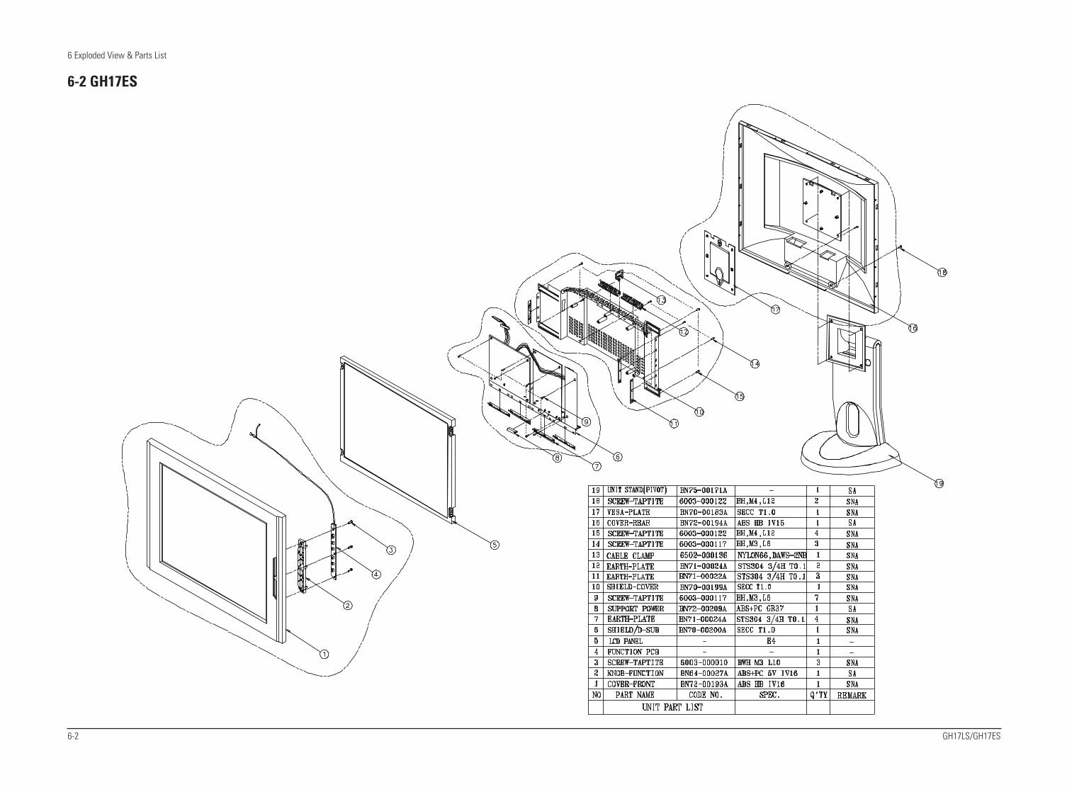
GH17LS/GH17ES 10-1
10 Schematic Diagrams
10-1 Main Part Schematic Diagram
RxO0-RxO0+RxO1-RxO1+RxO2-RxO2+GNDRxOC-RxOC+RxO3-RxO3+RxE0-RxE0+GNDRxE1-RxE1+GNDRxE2-RxE2+RxEC-RxEC+RxE3-
GNDRxE3+
NCNC
NC
5V5V5V
12V_BL
H:WHITEL:BLACK
BASIC TOUCH SCREEN
H:NORMALL:DPMS
R25810K10K
R257
+5V
1
R25610K
TP137 1
TP1381
TP139
560R270
10nFC121
CPU+5V
F
7 G
8H
10uFC122
NM24C17FM8XIC103
1A
2B
3C
4D
5E
6
R3460
+5V
TP1531
TP1561
TP1461
TP163
1
TP161 1
TP162 1
1
TP159 1
TP160 1
1
TP157 1
TP158
1
TP154 1
TP155
1
TP151 1
TP152
TP148 1
TP149 1
TP150
TP1451
TP1471
TP143 1
TP1441
1
TP1411
TP142 1
1
TP166
1
TP140
1
TP164
1
TP165
TP167
100
100R330
R334R336 R337 100
100
100
100R335
R34
2R
343CPU+5V
R34
110
010
0
1K
R3444.7K
2SC2412K-QQ111B
C
E
R345
R26
222
0R
338
R33
90
0
0R
340
0R332R333
R331 0
5101/16W
1/16W330R315
R310
R317
1/16W510R311
1/16W510
R3095101/16W
1K1/16W
R328
Q1092SC2412K-Q
B
C
E
R3073301/16W
R316
1/16W470R327
1/16W1K
1/16W330
2SC2412K-QQ110
B
C
E
R318
R192R191180K 180K
FT113
A1
B2
3.3VJP
slcon3pCN108
123
16V47uFC194
B
16V10uFC193
BD107
B
BD108
BD106
B
100R107
R108 100
R103 100
C189
C1900.002nF
0.002nF
100uF25V
C1880.002nF
R2961K
CPU+5V
C192
CPU+5VR29710K
10K 4.7KR298
100nFC191
R299
1
100nFC187
1
TP132
1
TP133
1
TP130
1
TP128
TP126
1
TP
135
1
TP
136
TP134
1
TP125
1
TP129
1
TP131
1
TP1091
TP127
1
TP1071
TP108
1
1
TP1021
TP1011
1
TP1041
TP103
1
TP106
1
TP105
1
TP1231
TP124
TP1171
TP1211
TP122
TP1141
TP115
1
TP1121
TP1131
TP1101
TP1111
1
TP119
1
TP120
1
TP116
1
TP118
+12V_INVERTER+12V_MAIN
10uFC185
R204 100
C184100nF
2.5VJA1
R202 22
100K
R201 10K
S23
2SC2412K-QQ108B
C
E
R269
SI9933ADY-T1IC118
8D1
D1_1 76
D2
D2_1 5
2 G1
4G2
S11
75R268
+5V
+5V
C183100pF
3.3uFC166
+5V
CPU+5V
CPU+5V
C145100nF
MAIN5VSS24D107
CPU+5V
CPU+5V
10K
MAIN5V
Q107B
C
E
R199
GND
IN OUT
R251100K
FT109
1A
2B
IC115BA17805FP
B
FT110
A1
B2
+3.3V
LVDS3.3V
FT112
1A
2C18147uF
C180100nF
C182100nF
IN OUT
C17910uF
+5V
BA033FPIC112
GND
C177100nF
120uFC175 C176
47uF
+2.5V
100nFC178
R265
470R266
ADJ
3
1VIN
2VOUT_1
4
VOUT_2
470
100nFC173
IC117LM317SX
47uFC172C171
47uF
PLL_2.5V
C174100nF
470
R264 470
LM317SXIC116
3
ADJ
VIN1
VOUT_12
VOUT_2
4 R263
C169100nF
100nFC170
C16810uF
CPU+5V
+12V_MAINCPU+5V
R19
84.
7K
R25
04.
7KR
197
R24
94.
7K4.
7K
4.7K
R24
8
4.7K
R19
34.
7K
4.7K
R24
5R
246
10KR195
1000nFC164
1000nFC162
C163 1000nF
2.5VJA1
3.9KR194
100nFC165
R185100K
7.5KR247
E
10KR184
B
C
EQ106
B
C
CPU+5V
Q105
0
0R190
R188
R189
8
R187 0
0
slcon8pCN107
1
2
3
4
5
6
7
R17
610
K
10K
R17
5
10K
R17
3
R17
410
K
R17
210
K
C150
10K
R17
1
10nF
10nF
10nFC151 C152C149 C148
10nF10nF 10nF
CPU+5V
CPU+5V
C147
10K
1/16W10KR110
100R168
R167
R14
710
0
100
100
R14
6
100R159
R14
5
R158 100
100100R157
100R155R156
R154 100
100
100R153
100R150
R151
R149 100
1A
2B
I+5V
100R148
10K
CPU+5V
BD1054.7K
R170
Q1032SC2412K-Q
B
C
E
R169
65D2_1
G12
G24
1S1
3 S2
LCD+5VIC107SI9933ADY-T1
D1 87D1_1
D2
R160
10KR162
Q101
B
C
E
100K
100nFC146
10
11
12
slcon2pCN106
1 2
1
2
3
4
5
6
7
8
9
4
5
6
7
+5V
+12V_INVERTER
slcon12pCN103
I+5V
slcon7pCN105
1
2
3
BD104BLM41P600S1
A
2B
10nFC143
10
11
12
13
14
C144100uF25V
1
2
3
4
5
6
7
8
9
CN104slcon14p_1
C123
10nF
CPU+5V
CPU+5V
R166R165
4.7K
28A14
29
NC
/A17
30
*WE
31
VC
C
32
4.7K
20
DQ721
*CE22
A1023
*OE24
A1125
A926
A8 27A13
DQ013
DQ
1
14
DQ
2
15
VS
S
16
DQ
3
17
DQ
4
18
DQ
5
19
DQ
6
A75
A66
A57
A48
A39
A210
A111
A012
20
IC110
AT27C010-90JC
VP
P
1
A16
2
A15
3
A12
4
12
M13
N14
15O
16P
17Q
18R
S19
T
4
E5
F6
7G
H8
I9
J10
K11
L
IC109
SN74ABT573
A1
B2
C3
D
1K
CPU+5V
ZD106
A1
2B
3 C
R152
C13010nF
R208
C13210uF10uF
C131
CPU+5V220
OUT
C129100nF
CPU+5V
KIA7045RTFIC105
GND_1
GND_2
IN
4.7K
R13
4
R137
R13
34.
7K
100
100
22pFC136
R131
X101
Q0 Q1
22pFC153
32
RST10
VC
C
44
35VPP
22
VS
S
1
VS
S1
21
XTA
L1
20
XTA
L2
P2_630
P2_731
P3_011
13P3_1
14P3_2
15P3_3
16P3_4
17P3_5
18
P3_
6
19
P3_
7
PSEN_
5
P1_
3
6
P1_
4
P1_57
P1_68
P1_79
P2_
0
24
P2_
1
25
P2_
2
26
P2_
3
27
P2_
4
28
P2_529
43
P0_
1
42
P0_
2
41
P0_
3
40
39P0_4
38P0_5
37P0_6
36P0_7
2
P1_
0
3
P1_
1
4
P1_
2
IC106TS80C32X2-MCB
ALE33
NIC112
NIC
2
23
34NIC3
P0_
0
C128100nF
C127100nF
100nFC114
C126100uF
100nFC112 C113
100nF
18
19
20
21
22
23
24
25
26
C11110uF
8
9
10
11
12
13
14
15
16
17
27
28
29
30
1
2
3
4
5
6
7
R123 0
CN102slcon30p
0R122R121 0
0R126 0
R124 0R125
R144 0
0R142R143 0
0R141R140 0
0
R139 0
R136 0R138
0R135
0R1300R132
0R129
R1270R128
47R118
0
10K
LVDS3.3V
10KR119R120
R116R117 10K
10K
10K
10KR111R115
SGM32F1E104-2AFT102
A 12 BC
3
LVDS3.3V
C117100nF 100nF
C118100nFC116
C11510uF
LVDS3.3V
100nF
SGM32F1E104-2AFT104
1AB2
3
C
C102 C104100nF
C103100nF
C106100nFC105
10uFC107
LVDS3.3V
100nFSGM32F1E104-2AFT101
A1 2BC
3
77 76
R26
R27
75
R_FB2021
R_FDE
Vcc_1
53
Vcc_2
67
82
Vcc
_3
Vcc
_4
97
Vsync
55
7R13
R1465
R15
R1643
R17
84
R20
R21
81 80
R22
R23
79 78
R24
R25
22
PLLGND_11617
PLLGND_2
19PLLGND_3
15PLLSEL
PLLVCC_112
PLLVCC_218
PRE14
R10109
R11
R128
GND_2
GN
D_3
8398
GN
D_4
54Hsync
25LVDSGND_1
35
LVD
SG
ND
_2
43
LVD
SG
ND
_3
LVDSGND_4
51
LVD
SV
CC
_1
30
LVD
SV
CC
_2
40
LVD
SV
CC
_3
48
PD_
74G20
G21
7372
G22
G23
7170
G24
G25
69
66G26
G27
65
13GND
52GND_1
68
CLKIN
56DE
23DUAL
G1021
G11
100
G12
G13
99 96
G14
G15
95 94
G16
G17
93
B22
B23
6160
B24
B25
5958
B26
B27
57
BAL24
CLK
1M
4241
CLK
1P
27
CLK
2M
CLK
2P
26
11
92
B10
B11
9190
B12
B13
89 88
B14
B15
87 86
B16
B17
85
64B20
B21
6362
4439
A3M
A3P
3837
A4M
A4P
36
A5M
3433
A5P
A6M
3231
A6P
29
A7M
A7P
28
DS90C387VJDIC102
A0M
5049
A0P
47
A1M
A1P
4645
A2M
A2P
LCD+5V
BD101
1
A B
2
R196 100
C125100nF
C12410uF
VCC14
FT106SGM32F1E104-2A
A 12 BC
3
IN4
A213
A310
B0IN
2
B1IN
5
B212
B39
GNDIN7
O_1IN6
O_211
O_38
B2
C 3
74F132D(REEL)IC104
0_0IN3
A0IN1
A1
ZD102
1
A
B2
C3
ZD103
1A
ZD101
1
A
B 2
C3
100nFC101
R101
100R104
4.7K4.7K
100R106
R1024
7WC_
R105100
24LC21AT-/SNIC101
NC_11
NC_22
NC_33 6SCL
5SDA
8VCC
VSS
6
7
8
9
10
11
12
13
14
15
CN101d_sub15p
1
2
3
4
5
1 2
3
100R109
FT103
A 12 BC
3
D1043 D102
1 2
3
1 2
3 D103
1 2
D105
1 2
3
D101
3
FT105
1AB2
3
C
1
2
3
D106
1 21
2
3
ZD105
R11475
ZD104
75R113R112
75
LED1
LED
LED_R
LED_G
CR
EF
CT
RL
LED
1S
ELF
RA
ST
_D_S
UB
PA
NE
L_O
N_O
FF
BL_
ON
AUTOMCALE
MAIN_ON_OFFMAIN_ON_OFF
JAG_RST
AHS
CTRL
LED_R
ME
NU
GREEN1N
BLUE1NBLUE1N
AUTOPOWER
LEFTEXIT
RXDTXD
RESET
MCA16
RIGHTLED_G
MENU
PANEL_ON_OFF
RED1P
GREEN1P
BLUE1P
CTRL
MC
AD
(3)
MCRD
RED1NRED1N
GREEN1N
MCA(11)
MCA(9)MCA(8)MCA(13)MCA(14)
MCA(8:15)
MCAD(3)
MCA(7)
MCAD(0:7)
MCA(8:15)
MCA(0:7)
LEF
T
LEDPOWER
RXD
TXD
BL_ON
BL_CNT
MCA(6)
MCA(6)
MCA(5)
MCA(5)
MCA(4)
MCA(4)
MCA(3)
MCA(3)
MCA(2)
MCA(2)
MCA(1)MCA(1)
MCA(0)MCA(0)
MCALE
MCAD(0:7)MCA16
MCAD(0)
MCAD(4)MCAD(5)
*PSEN
MCAD(0:7)
MCAD(1)MCAD(2)
MCAD(6)MCAD(7)
MCA(15)MCA(12)
MCA(10)
MC
A(1
0)M
CA
(11)
MC
A(1
2)
MCA(13)MCA(14)MCA(15)CTRL
MCWR
*PSEN
RESET
MCAD(7)
MCAD(5)
MCAD(3)
MCAD(1)
MCAD(6)
MCAD(4)
MCAD(2)
MCAD(0)
MCA(7)
DCLK
LVDS_EN
MCALE
MC
AD
(0)
MC
AD
(1)
MC
AD
(2)
MCAD(4)MCAD(5)MCAD(6)MCAD(7)
RIG
HT
EXIT
MC
A(8
)M
CA
(9)
DA
GR
N(4
)D
AG
RN
(5)
DA
GR
N(6
)D
AG
RN
(7)
DABLU(0:7)
DA
BLU
(0)
DA
BLU
(1)
DA
BLU
(2)
DA
BLU
(3)
DA
BLU
(4)
DA
BLU
(5)
DA
BLU
(6)
DA
BLU
(7)
DENDVSDHS
DBGRN(0:7)DBGRN(0)DBGRN(1)DBGRN(2)DBGRN(3)DBGRN(4)DBGRN(5)
DBGRN(6)DBGRN(7) DBBLU(0:7)
DBBLU(0)DBBLU(1)DBBLU(2)DBBLU(3)DBBLU(4)DBBLU(5)DBBLU(6)DBBLU(7)
DARED(0:7)
DARED(0)DARED(1)DARED(2)DARED(3)DARED(4)
DARED(5)DARED(6)
DARED(7)
DAGRN(0:7)
DAGRN(0)DAGRN(1)
DA
GR
N(2
)D
AG
RN
(3)
AHS
AVS
V_SYNCH*V_SYNC
DBRED(0:7)
DB
RE
D(0
)
DB
RE
D(1
)D
BR
ED
(2)
DB
RE
D(3
)D
BR
ED
(4)
DB
RE
D(5
)D
BR
ED
(6)
DB
RE
D(7
)
RED1N
GREEN1N
BLUE1N
SELFRAST_D_SUB
AVS
1
7

10 Schematic Diagrams
10-2 GH17LS/GH17ES
1 7
10 Schematic Diagrams
GH17LS/GH17ES 10-3
10-2 Main Part Schematic Diagram
1
10K
+5V
TP168
10KR347 R348
FT
205
A1
B2
6.3V
120uFC272
L201
3.3U
H
R224 0
3.3VJF
22
R255
1A
2B
100nFC267
R24322
FT203
X201
GND
2NC
1
OUT
3VDC
4
100R254
R27
810
K
10K
R27
9
0
R25
310
K0R
274
R27
3
R27
50 00
R27
6
N4
Y4
VS
SC
8
A22 VSSP1D22
VSSP2
XINA6
XOUTA7
XVDDD7XVSS
B7
R27
7
VS
S49
VSS5L16
VS
S50
AC
5
M11VSS6VSS7 M12
M13VSS8VSS9 M14
VS
SC
3G
23N
23V
SS
C4
VS
SC
5W
23
D4
VS
SC
6
VS
SC
7
T15VSS34VSS35
T16
VS
S39
A23
L15VSS4
VS
S40
F26
VS
S41
L26
VS
S42
R26
VS
S43
AC
26
VS
S44
AF
23
VS
S48
C1
N1
VSS24VSS25
R12
R13VSS26
VSS27R14
R15VSS28VSS29
R16
VSS3L14
T11VSS30VSS31
T12T13
VSS32VSS33
T14
VSS14VSS15 N14
N15VSS16VSS17 N16
P11VSS18VSS19
P12
L13VSS2
P13VSS20VSS21
P14P15
VSS22
VSS23P16
R11
VD
DC
8H
4R
4V
DD
C9
B22VDDP1
C22 VDDP2
L11VSS0VSS1
L12
M15VSS10VSS11
M16
N11VSS12VSS13 N12
N13
AF
26
VD
D9
A5
AC20VDDC0VDDC1
AC14
VD
DC
10A
B4
AC8VDDC2
D23
VD
DC
3V
DD
C4
K23
T23
VD
DC
5V
DD
C6
AB
23D
21V
DD
C7
D1
VDD0AF21AF16
VDD1
K1
VD
D10
AA
1V
DD
11
VDD2AF10
A26
VD
D3
VD
D4
J26
N26
VD
D5
VD
D6
U26
Y26
VD
D7
VD
D8
SD
D62
A24
A25
SD
D63
SD
D7
AE
24
SD
D8
AF
24
SD
D9
AC
25
SD
RA
SP
24
R25
SD
WE
D19 SVDD
B19SVSS
E1
SY
SR
ST
TE
ST
D25
D26
SD
D53
SD
D54
C23
C24
SD
D55
SD
D56
C25
C26
SD
D57
SD
D58
B23
B24
SD
D59
SD
D6
AD
24
SD
D60
B25
B26
SD
D61
G25
G26
SD
D43
SD
D44
F23
F24
SD
D45
SD
D46
F25
E23
SD
D47
SD
D48
E24
E25
SD
D49
SD
D5
AC
24
SD
D50
E26
D24
SD
D51
SD
D52
K26
SD
D33
SD
D34
J23
J24
SD
D35
SD
D36
J25
H23
SD
D37
SD
D38
H24
H25
SD
D39
SD
D4
AE
23
SD
D40
H26
G24
SD
D41
SD
D42
Y24
SD
D24
Y25
SD
D25
W24
SD
D26
W25
SD
D27
W26
SD
D28
L23
SD
D29
L24
SD
D3
AD
23
SD
D30
L25
SD
D31
K24
SD
D32
K25
AD
26
SD
D14
AE
26
SD
D15
AB
24
SD
D16
AB
25
SD
D17
AB
26
SD
D18
AA
23
SD
D19
AA
24
SD
D2
AC
23
SD
D20
AA
25
SD
D21
AA
26
SD
D22
Y23
SD
D23
SD
CK
ER
24
T25
SD
CK
FB
P23
SD
CK
N
SD
CK
PR
23
SD
CS
0M
26
SD
D0
AD
22
SD
D1
AE
22
SD
D10
AD
25
SD
D11
AE
25
SD
D12
AF
25
SD
D13
V24
SD
A10
N25
SD
A2
V25
SD
A3
V26
SD
A4
U23
SD
A5
U24
SD
A6
U25
SD
A7
P25
SD
A8
P26
SD
A9
N24
T26
SD
CA
S
R2P
C15 RREFHC14
RREFL
D14 RVDD1
D13RVDD2
B14 RVSS1
B13RVSS2
SC
DT
_GP
IO0
E2
SC
LF
3
F4
SD
A
SD
A0
V23
SD
A1
PHSYNC AE21
AF12PNLCLK
PSHFCLKAC13
D20PVDD1
B20PVSS1
AC21PVSYNC
PWM1 B1
A12R1N
A13 R1P
A10R2N
A11
PD6
PD60AC22
AC17PD61
PD62AC11
AF19PD63PD64 AF13
AF8PD65
PD7AE15
AF15PD8
PD9AC16
AF20PDE
AC10
AF14PD4
AD10PD40
PD41AE10AD11
PD42PD43
AE11AF11
PD44PD45 AC12
AD12PD46PD47 AE12
PD5AC15AD15
PD3AE14
AD7PD30PD31 AE7
AF7PD32
PD33AD8AE8
PD34PD35 AC9
AD9PD36PD37 AE9
AF9PD38PD39
PD2
AD19PD20
PD21AE19AD20PD22
PD23AE20
AF5PD24PD25 AC6
AD6PD26PD27 AE6
AF6PD28PD29 AC7
AE13
AD16PD10
PD11AE16AD17PD12
PD13AE17
AF17PD14PD15
AC18
AD18PD16PD17
AE18AF18PD18
PD19AC19
AD14
AD
2P
C9
PC
FIE
LD_G
PIO
3A
E5
AB
2P
CH
RE
FP
CH
SY
NC
AB
3
PC
LKA
G4
PC
LKB
P4
PC
LKC
AA
4
AD
5P
CV
RE
F_G
PIO
2
AB
1P
CV
SY
NC
AD13PD0
PD1
AC
1A
C2
PC
13P
C14
AC
3A
C4
PC
15
PC
2A
F3
AF
4P
C3
PC
4A
E1
AE
2P
C5
PC
6A
E3
AE
4P
C7
PC
8A
D1
Y3
PB
5W
1
PB
6W
2
PB
7W
3
PB
8W
4
PB
9V
1
P3
PB
VS
YN
C
PC
0A
F1
AF
2P
C1
PC
10A
D3
AD
4P
C11
PC
12
PB
16U
4
PB
17T
1
PB
18T
2
PB
19T
3
PB
2Y
1
PB
20T
4
R1
PB
21P
B22
R2
R3
PB
23
PB
3Y
2
PB
4
M4
PA
8L1
PA
9L2
PB
0A
A2
PB
1A
A3
PB
10V
2
PB
11V
3
PB
12V
4
PB
13U
1
PB
14U
2
PB
15U
3J4
PA
19H
1
PA
2N
2
PA
20H
2
PA
21H
3
PA
22G
1
PA
23G
2
PA
3N
3
PA
4M
1
PA
5M
2
PA
6M
3
PA
7
PA
0P
1
PA
1P
2
PA
10L3
PA
11L4
PA
12K
2
PA
13K
3
PA
14K
4
PA
15J1
PA
16J2
PA
17J3
PA
18
A4
B4
MC
AD
5M
CA
D6
A3
B3
MC
AD
7
MC
AD
8C
3A
2M
CA
D9
D3
MC
ALE
MC
CS
C4
MC
RD
E3
E4
MC
WR
ME
MC
LKT
24
D2
C13 IREFHC12
IREFL
D12 IVDD1
D11IVDD2
B12 IVSS1
B11IVSS2
MC
AD
0B
6B
5M
CA
D1
MC
AD
2C
5D
5M
CA
D3
MC
AD
4
D16GVDD1
D15GVDD2
B16 GVSS1
B15GVSS2
HS
YN
C0
F2
D6
HS
YN
C1
HS
YN
C2
C6
HS
YN
CO
UT
C2
A8I1
A9 I2
INT
R
AF22AD21
ENVDD
A16 G1NA17
G1P
A14G2N
A15G2P
B2
GP
IO4
C21 GPVDD
B21GPVSS
C17GREFH
C16 GREFL
CLA
MP
OU
T
CVDD1D9
CVDD2D8 CVSS1B9
CVSS2B8
DE
INF
1
M23
DQ
M
M25
DQ
S
DVDDD10
DVSSB10
DV
SY
NC
G3
ENBKL
A21B1P
A18 B2NA19
B2P
BA
NK
M24
C19BREFH
C18BREFL
D18BVDD1
D17BVDD2
B18BVSS1
B17BVSS2
A1
C10AVDD1
AVDD2C11
AVDD3C8
AVDD4C9
C20 AVSS1
AVSS2C7
A20B1N
IC202JAGASM
100
100nF
R267
100nFC242
C241
C238 C239100nF
100nF
100nF
2.5VJA2
+2.5V
PLL_2.5V
2.5VJS
2.5VJS
C240
L2073.3UH
3.3UHL206
2.5VJA1
C21810uF
10uFC216
1A
2B
100R244
FT202
A1
B2
FT204
10uFC247
100nFC245
FT201
1A
2B
C246100nF
100nFC243
3.3VJF
C2441nF
10uFC268
C270
100nF
10
100nFC269
4.7uFC265
R242
C264100nF
R24047
2.5VJA2
100nFC271
10uFC260
C259100nF
R239 10
2.5VJA1
C257
4.7uF
2.5VJA1
C2581nF
10R238 1nFC256C255
10uF
100nFC252
2.5VJA1
100nFC250C251 100nF
C249 100nF
1nFC254
1nFC248
C253 1nF
2.2K
+5V
33KR236
R235
C
E
R23710K
3.3VJF
Q201B
C236 C237
100nF100nF
100nFC230
C231
100nF
C228 C229100nF100nF
100nF
C226 C227
100nF
C225100nF
100nFC223 C224
100nF100nF
100nFC219
C222
100nFC211
C213100nF
100nF
100nFC207
C209
R22
1
C201100nF
R22
310
0
100
100
R22
2R219
R22
50
R2590
0 100
R220
4
56
78
78
RA212 12
312
34
56
12
34
56
78
RA211
34
56
78
RA210
6
78
RA209
128
RA208 12
34
512
34
56
712
34
56
78
RA207
4
56
78
RA206
6
78
RA205
12
3
RA204 12
34
512
34
56
782
34
56
78
RA203
56
78
RA202 1
RA20112
34
C22110uF
R214
100R215
R21
60
100
0R
217
100
R23
210
0
R23
3
R23
4
R23
1
100
R23
010
010
0
R22
810
0R
229
3
4
5
6
7
8
100
6
7
8
RA
214
1
2
RA
213 1
2
3
4
5
R22
710
0
3.3VJF
100
R22
6
3.3VJP
10uFC210
+3.3V
3.3VJS
C20810uF
2.5VJF
10uFC202
10uFC214
2.5VJP
C220
10uF
2.5VJA2
2.5VJF
3.3VJS
3.3VJP
3.3VJF
2.5VJS
2.5VJP
2.5VJS
2.5VJA1 0
C21210uF
22R212
R213
R211 22
2222R261
R260
DABLU(4)DABLU(5)
DABLU(6)DABLU(7)
LVD
S_E
NA
UT
O
PANEL_ON_OFF
SE
LFR
AS
T_D
_SU
B
ME
NU
LED
1
DBGRN(0:7)DBGRN(0)
DBGRN(1)DBGRN(2)DBGRN(3)DBGRN(4)DBGRN(5)DBGRN(6)
DBGRN(7)
DBBLU(0:7)DBBLU(0)DBBLU(1)DBBLU(2)DBBLU(3)DBBLU(4)
DBBLU(5)DBBLU(6)
DBBLU(7)
DBRED(0:7)DBRED(0)DBRED(1)DBRED(2)DBRED(3)DBRED(4)
DBRED(5)DBRED(6)
DBRED(7)
DABLU(0:7)DABLU(0)DABLU(1)DABLU(2)DABLU(3)
MC
AD
(4)
MC
AD
(5)
MC
AD
(6)
MC
AD
(7)
MC
ALE
MC
RD
MC
WR
JAG
_RS
T
BL_CNT
BL_ON
MCA(8:15)
DARED(0:7)DARED(0)DARED(1)DARED(2)DARED(3)DARED(4)
DARED(5)DARED(6)
DARED(7)
DAGRN(0:7)DAGRN(0)
DAGRN(1)DAGRN(2)
DAGRN(3)DAGRN(4)DAGRN(5)DAGRN(6)DAGRN(7)
CREF
DVSDHSDENDCLK
H*V
_SY
NC
V_S
YN
C MC
A(8
)M
CA
(9)MCAD(0:7) MC
AD
(0)
MC
AD
(1)
MC
AD
(2)
MC
AD
(3)
BLUE1NBLUE1P
GREEN1NGREEN1P
RED1NRED1P
2
3
5 6
4

10 Schematic Diagrams
10-4 GH17LS/GH17ES
2
5
3
6
4

Samsung Electronics Co.,Ltd.416, Maetan-3Dong, Paldal-Gu, Suwon City, Kyungki-Do, Korea.Printed in KoreaP/N : BN68-00225C-00http://www.samsungmonitor.com (SyncMaster Worldwide)http://www.samsung-monitor.com (SyncMaster USA)http://www.sec.co.kr/monitor (Korea)
Related Documents