1 GGE2012 Advanced Surveying (Course Note) © Yong © Yong-Won Ahn / University Won Ahn / University Tutorials and Processing of GPS Survey Data of New Brunswick, Canada of New Brunswick, Canada © Yong-Won Ahn • Department of Geodesy and Geomatics Engineering • University of New Brunswick 1/00 Contents – Orbits (precise or broadcast) – Data rate and observation span Tutorials of GPS Survey – Elevation angle – Points to be observed on your lab. – Processing software and methodology – Processing GPS data A di WGS84 S t GPS H i ht © Yong-Won Ahn • Department of Geodesy and Geomatics Engineering • University of New Brunswick 2/00 – Appendix: WGS84 System, GPS Height

Welcome message from author
This document is posted to help you gain knowledge. Please leave a comment to let me know what you think about it! Share it to your friends and learn new things together.
Transcript
1
GGE2012 Advanced Surveying (Course Note)
© Yong© Yong--Won Ahn / University Won Ahn / University
Tutorials and Processing of GPS Survey Data
of New Brunswick, Canadaof New Brunswick, Canada
© Yong-Won Ahn • Department of Geodesy and Geomatics Engineering • University of New Brunswick1/00
Contents– Orbits (precise or broadcast)
– Data rate and observation span
Tutorials of GPS Survey
p
– Elevation angle
– Points to be observed on your lab.
– Processing software and methodology
– Processing GPS data
A di WGS84 S t GPS H i ht
© Yong-Won Ahn • Department of Geodesy and Geomatics Engineering • University of New Brunswick2/00
– Appendix: WGS84 System, GPS Height
2
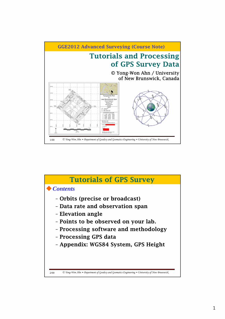
• GPS measures ranges.
• If a reference station is on a
Tutorials of GPS SurveyRecording GPS observation
known location then the range can be calculated.
• The difference between the measured and calculated ranges is measurement error.
• The error measured at a f t ti i i il t
Error
© Yong-Won Ahn • Department of Geodesy and Geomatics Engineering • University of New Brunswick3/00
reference station is similar to the error measured by nearby receivers ( differential approach)
GPS Orbits
Tutorials of GPS Survey
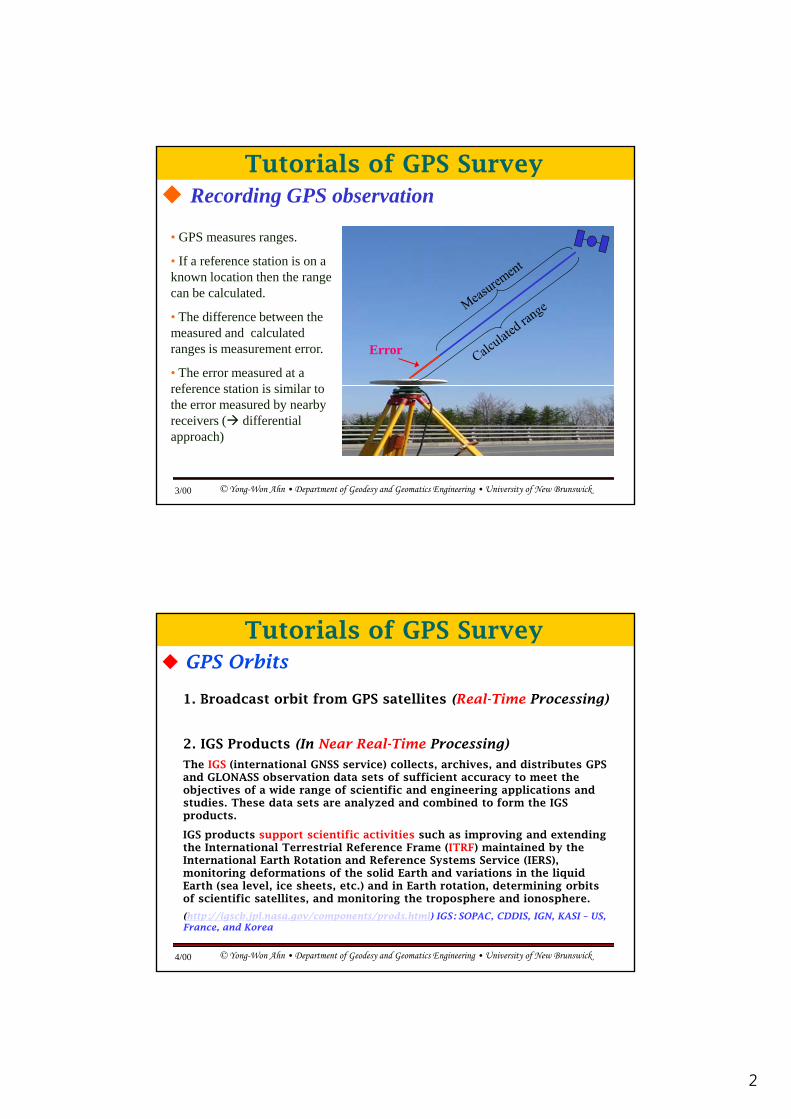
1. Broadcast orbit from GPS satellites (Real-Time Processing)
2. IGS Products (In Near Real-Time Processing)
The IGS (international GNSS service) collects, archives, and distributes GPS and GLONASS observation data sets of sufficient accuracy to meet the objectives of a wide range of scientific and engineering applications and studies. These data sets are analyzed and combined to form the IGS products.
IGS products support scientific activities such as improving and extending the International Terrestrial Reference Frame (ITRF) maintained by the
© Yong-Won Ahn • Department of Geodesy and Geomatics Engineering • University of New Brunswick4/00
( ) yInternational Earth Rotation and Reference Systems Service (IERS), monitoring deformations of the solid Earth and variations in the liquid Earth (sea level, ice sheets, etc.) and in Earth rotation, determining orbits of scientific satellites, and monitoring the troposphere and ionosphere.
(http://igscb.jpl.nasa.gov/components/prods.html) IGS: SOPAC, CDDIS, IGN, KASI – US, France, and Korea
3
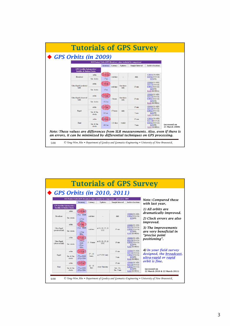
GPS Orbits (in 2009)
Tutorials of GPS Survey
© Yong-Won Ahn • Department of Geodesy and Geomatics Engineering • University of New Brunswick5/00
Note: These values are differences from SLR measurements. Also, even if there is an errors, it can be minimized by differential techniques on GPS processing.
(accessed on 21 March 2009)
GPS Orbits (in 2010, 2011)
Tutorials of GPS Survey
Note: Compared these with last year,
1) All orbits are dramatically improveddramatically improved.
2) Clock errors are also improved.
3) The improvements are very beneficial in “precise point positioning”.
© Yong-Won Ahn • Department of Geodesy and Geomatics Engineering • University of New Brunswick6/00
(accessed on 22 March 2010 & 22 March 2011)
4) In your field survey designed, the broadcast, ultra-rapid or rapidorbit is fine.
4
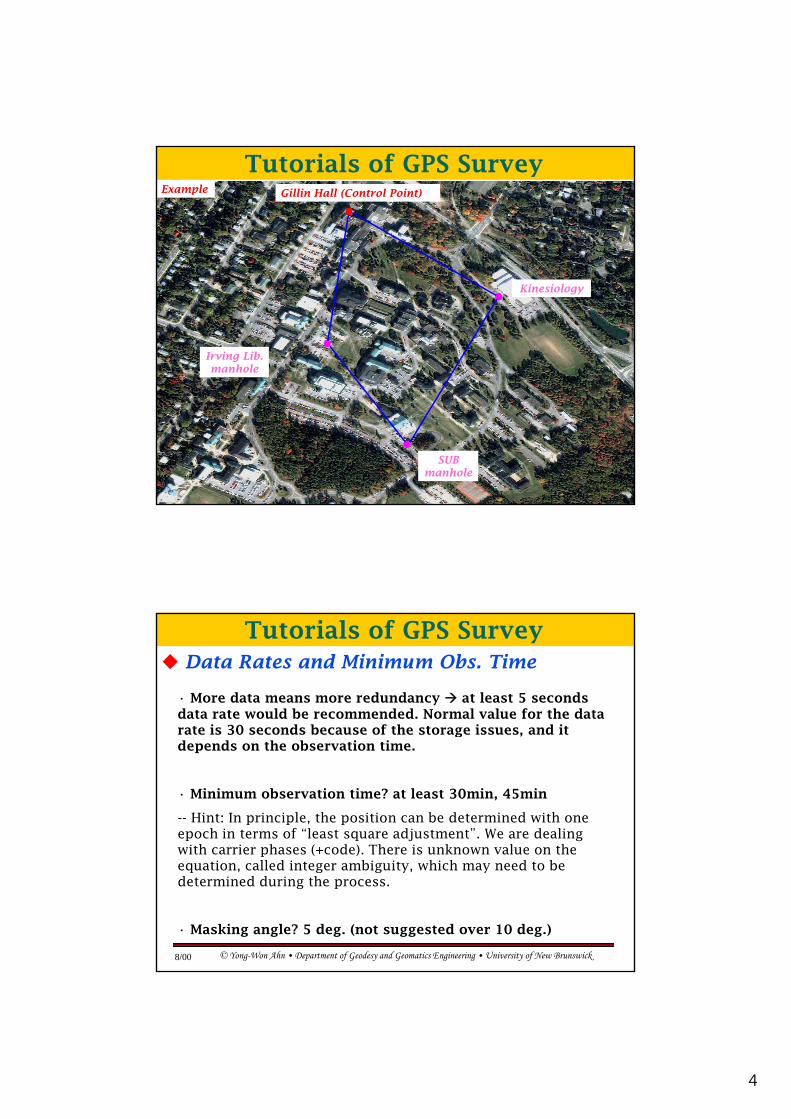
Gillin Hall (Control Point)
Tutorials of GPS SurveyExample
Kinesiology
Irving Lib. manhole
© Yong-Won Ahn • Department of Geodesy and Geomatics Engineering • University of New Brunswick7/00
SUB manhole
Data Rates and Minimum Obs. Time
Tutorials of GPS Survey
• More data means more redundancy at least 5 seconds data rate would be recommended. Normal value for the data rate is 30 seconds because of the storage issues and it rate is 30 seconds because of the storage issues, and it depends on the observation time.
• Minimum observation time? at least 30min, 45min
-- Hint: In principle, the position can be determined with one epoch in terms of “least square adjustment”. We are dealing with carrier phases (+code) There is unknown value on the
© Yong-Won Ahn • Department of Geodesy and Geomatics Engineering • University of New Brunswick8/00
with carrier phases (+code). There is unknown value on the equation, called integer ambiguity, which may need to be determined during the process.
• Masking angle? 5 deg. (not suggested over 10 deg.)
5
[Geodetic Software – post mission, examples]
: Bernese GPS Software (from AIUB – Astronomical Institute of University of Bern, Bern, Switzerland, Available for our GGE
Tutorials of GPS SurveyGPS Processing Software:
department, academic & commercial)
: GIPSY-OASIS II (from NASA JPL, free)
: GAMIT (from MIT), DIPOP (from UNB, free)
[Commercial Software– post mission mostly, examples]
: TGO™ (Trimble Geomatics Office)
: TTC™ (Trimble Total Control) Topcon Tools Leica Geosystem’s Ski Pro
© Yong-Won Ahn • Department of Geodesy and Geomatics Engineering • University of New Brunswick9/00
: TTC™ (Trimble Total Control), Topcon Tools, Leica Geosystem s Ski Pro
: GrafNav™ (from NovAtel Inc., Calgary)
: MultiRef™, FlyKin™ (from Geomatics Eng. at U of Calgary)
: UNB-RTK (from GGE), Precise Point Positioning (free software, NRCan(Canada), Auto-GIPSY (NASA, ~free), UNB-GAPS (UNB, free)) etc.
[Measurements from a GPS Rx, Trimble, Leica, or TOPCon receiver]
: C/A Code, L1 phase, (+ L2 phase, P2 code)
Tutorials of GPS SurveyGPS Processing Methodology
1. Short baseline case – same atmosphere (at UNB campus)
: C/A and L1 code/carrier phase measurements
: Never use the L1 and L2 combination, e.g. ionosphere-free linear combination due to the amplification of the noise.
: GGE2012 practice.
© Yong-Won Ahn • Department of Geodesy and Geomatics Engineering • University of New Brunswick10/00
2. Longer baseline case – different atmosphere (over 10 km)
: Either C/A + L1 phase with the method of atmospheric error mitigation, or C/A + both L1 and L2 phase combination to mitigate errors mainly by the ionosphere. Frequently, this combination is referred to as “ionosphere-free combination”: GGE2013 practice.
6
GPS Processing Introduction: TGO™
: Post mission
Processing GPS Data
: Solutions are too optimistic (only mathematical correlation is considered)
: Limited analysis
: Commercial software can hardly guarantee the accuracy of less than cm from the true value in static mode. In a real-time mode or RTK mode, the achievable accuracy is lower. You must be very careful for this.
: For those who works for map-matching, land property management,
© Yong-Won Ahn • Department of Geodesy and Geomatics Engineering • University of New Brunswick11/00
: For those who works for map matching, land property management, or low-precision GIS which don’t need a high-precision application
: For those who study for geodetic accuracy, please use other geodetic software stated before.
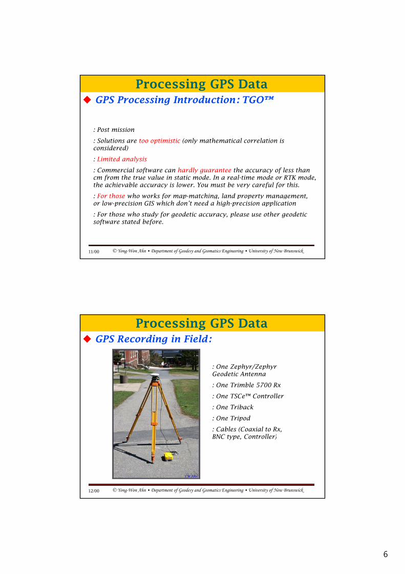
GPS Recording in Field:
: One Zephyr/Zephyr Geodetic Antenna
Processing GPS Data
Geodetic Antenna
: One Trimble 5700 Rx
: One TSCe™ Controller
: One Triback
: One Tripod
: Cables (Coaxial to Rx, BNC type Controller)
© Yong-Won Ahn • Department of Geodesy and Geomatics Engineering • University of New Brunswick12/00
BNC type, Controller)
7
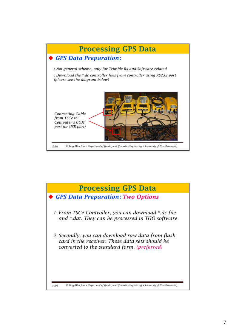
GPS Data Preparation:
: Not general scheme, only for Trimble Rx and Software related
: Download the *.dc controller files from controller using RS232 port (please see the diagram below)
Processing GPS Data
(please see the diagram below)
Connecting Cable
© Yong-Won Ahn • Department of Geodesy and Geomatics Engineering • University of New Brunswick13/00
gfrom TSCe to Computer’s COM port (or USB port)
GPS Data Preparation: Two Options
1. From TSCe Controller, you can download *.dc file and * dat They can be processed in TGO software
Processing GPS Data
and .dat. They can be processed in TGO software
2. Secondly, you can download raw data from flash card in the receiver. These data sets should be converted to the standard form. (preferred)
© Yong-Won Ahn • Department of Geodesy and Geomatics Engineering • University of New Brunswick14/00
8
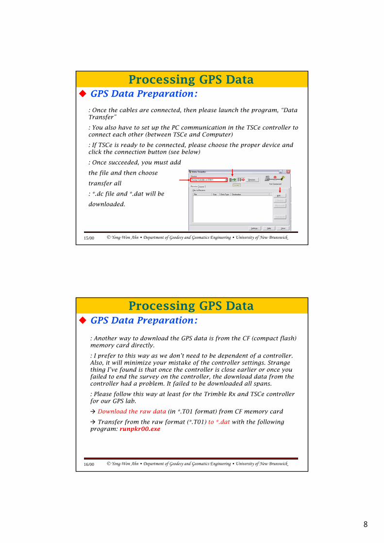
GPS Data Preparation:
: Once the cables are connected, then please launch the program, “Data Transfer”
: You also have to set up the PC communication in the TSCe controller to
Processing GPS Data
: You also have to set up the PC communication in the TSCe controller to connect each other (between TSCe and Computer)
: If TSCe is ready to be connected, please choose the proper device and click the connection button (see below)
: Once succeeded, you must add
the file and then choose
transfer all
© Yong-Won Ahn • Department of Geodesy and Geomatics Engineering • University of New Brunswick15/00
: *.dc file and *.dat will be
downloaded.
GPS Data Preparation:
: Another way to download the GPS data is from the CF (compact flash) memory card directly.
: I prefer to this way as we don’t need to be dependent of a controller
Processing GPS Data
: I prefer to this way as we don t need to be dependent of a controller. Also, it will minimize your mistake of the controller settings. Strange thing I’ve found is that once the controller is close earlier or once you failed to end the survey on the controller, the download data from the controller had a problem. It failed to be downloaded all spans.
: Please follow this way at least for the Trimble Rx and TSCe controller for our GPS lab.
Download the raw data (in *.T01 format) from CF memory card
© Yong-Won Ahn • Department of Geodesy and Geomatics Engineering • University of New Brunswick16/00
Download the raw data (in .T01 format) from CF memory card
Transfer from the raw format (*.T01) to *.dat with the following program: runpkr00.exe
9
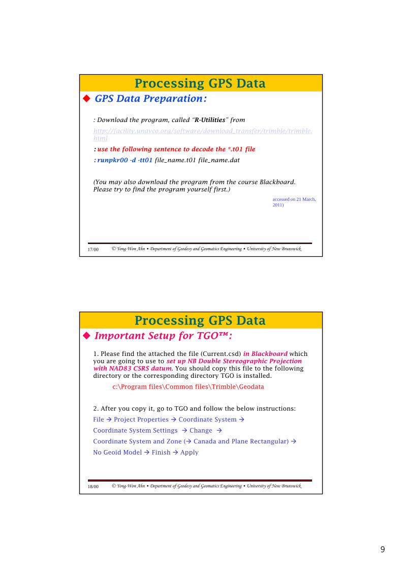
GPS Data Preparation:
: Download the program, called “R-Utilities” from
http://facility.unavco.org/software/download_transfer/trimble/trimble.
Processing GPS Data
html
: use the following sentence to decode the *.t01 file
: runpkr00 -d -tt01 file_name.t01 file_name.dat
(You may also download the program from the course Blackboard. Please try to find the program yourself first.)
© Yong-Won Ahn • Department of Geodesy and Geomatics Engineering • University of New Brunswick17/00
accessed on 21 March, 2011)
Important Setup for TGO™:
1. Please find the attached the file (Current.csd) in Blackboard which you are going to use to set up NB Double Stereographic Projection with NAD83 CSRS datum. You should copy this file to the following
Processing GPS Data
directory or the corresponding directory TGO is installed.
c:\Program files\Common files\Trimble\Geodata
2. After you copy it, go to TGO and follow the below instructions:
File Project Properties Coordinate System
Coordinate System Settings Change
© Yong-Won Ahn • Department of Geodesy and Geomatics Engineering • University of New Brunswick18/00
y g g
Coordinate System and Zone ( Canada and Plane Rectangular)
No Geoid Model Finish Apply
10
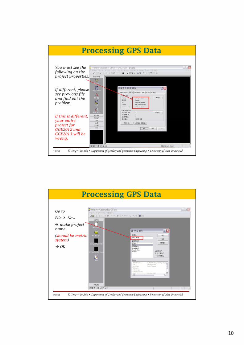
You must see the following on the project properties.
Processing GPS Data
If different, please see previous file and find out the problem.
If this is different,
© Yong-Won Ahn • Department of Geodesy and Geomatics Engineering • University of New Brunswick19/00
your entire project for GGE2012 and GGE2013 will be wrong.
Go to
File New
make project
Processing GPS Data
make project name
(should be metric system)
OK
© Yong-Won Ahn • Department of Geodesy and Geomatics Engineering • University of New Brunswick20/00

11
Go to
File Import GPS data file (* d t)
Processing GPS Data
(*.dat)
© Yong-Won Ahn • Department of Geodesy and Geomatics Engineering • University of New Brunswick21/00
You may see the following file lists on DAT check-in. Most important parts are the antenna height, antenna types, and reference points of antenna (either “bottom of notch, top of notch, or antenna phase center for each antenna which you used). You “HAVE TO” input the
Processing GPS Data
center for each antenna which you used). You HAVE TO input the corresponding values on each field “EXACTLY”. Most important !!!
© Yong-Won Ahn • Department of Geodesy and Geomatics Engineering • University of New Brunswick22/00
This includes: Antenna Height, Antenna Type, and Antenna Reference Point (Always use the Phase Center and input your “hand-calculated” phase center value for your antenna for exercise!!!
12
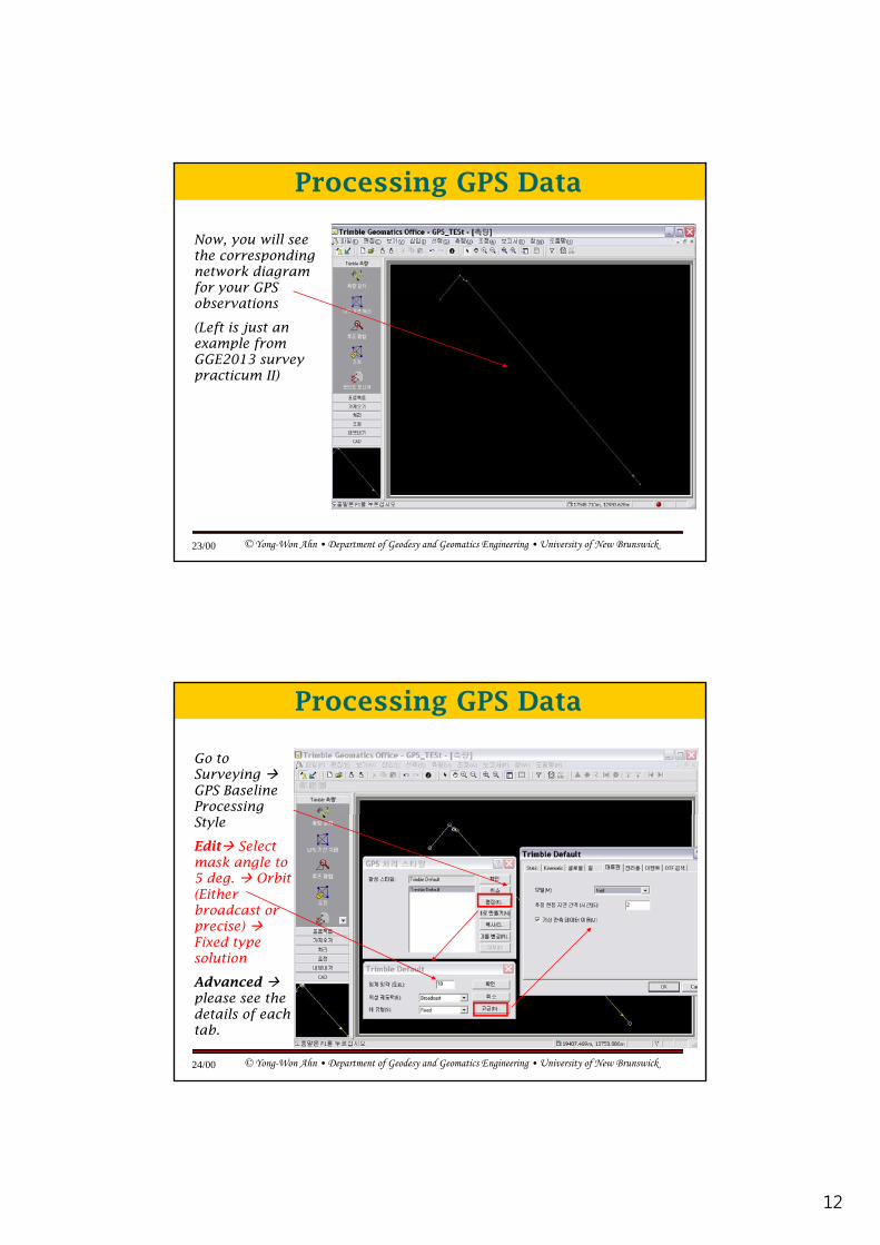
Now, you will see the corresponding network diagram for your GPS
Processing GPS Data
observations
(Left is just an example from GGE2013 survey practicum II)
© Yong-Won Ahn • Department of Geodesy and Geomatics Engineering • University of New Brunswick23/00
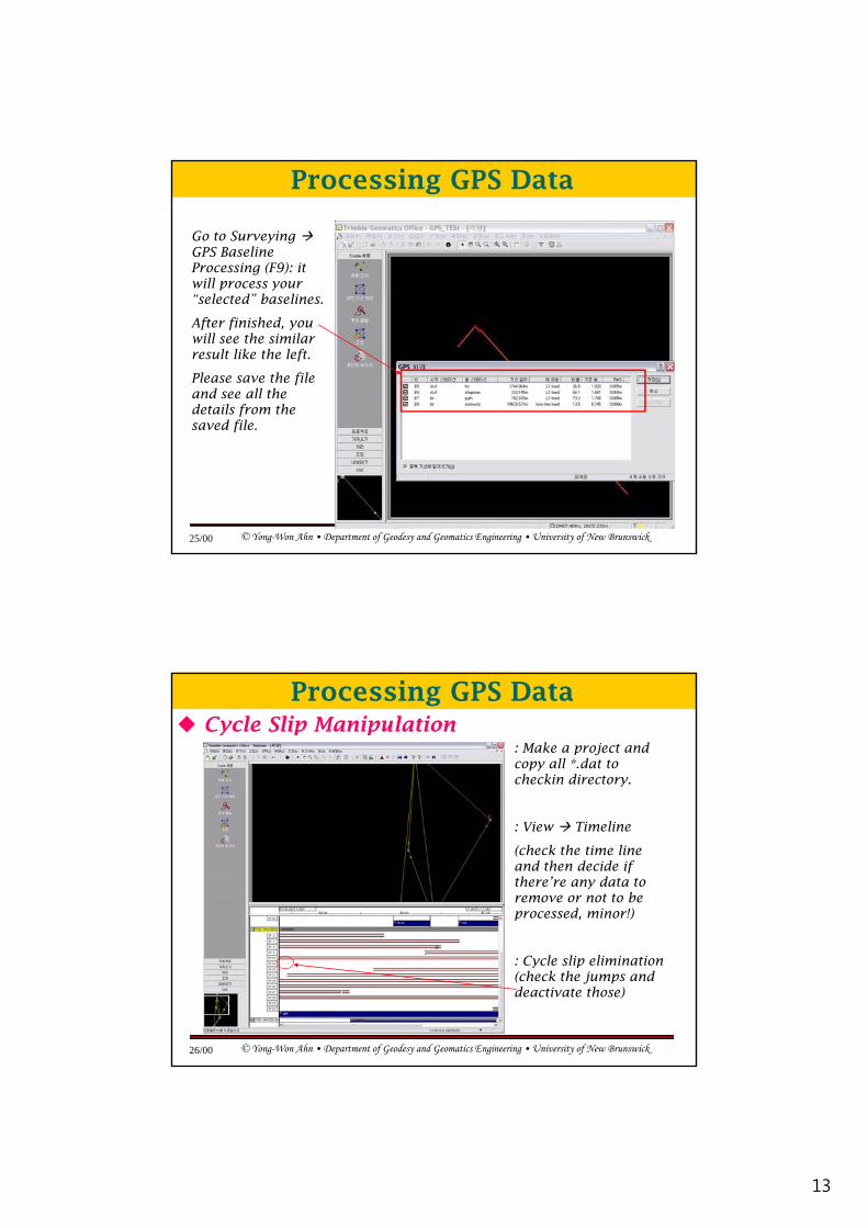
Go to Surveying GPS Baseline Processing
Processing GPS Data
Style
Edit Select mask angle to 5 deg. Orbit (Either broadcast or precise) Fixed type
© Yong-Won Ahn • Department of Geodesy and Geomatics Engineering • University of New Brunswick24/00
ypsolution
Advancedplease see the details of each tab.
13
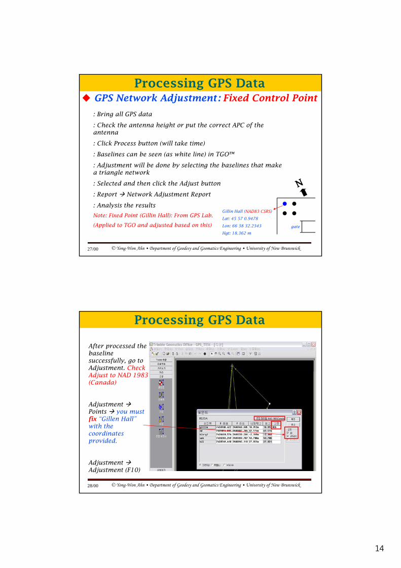
Go to Surveying GPS Baseline Processing (F9): it will process your
Processing GPS Data
“selected” baselines.
After finished, you will see the similar result like the left.
Please save the file and see all the details from the saved file
© Yong-Won Ahn • Department of Geodesy and Geomatics Engineering • University of New Brunswick25/00
saved file.
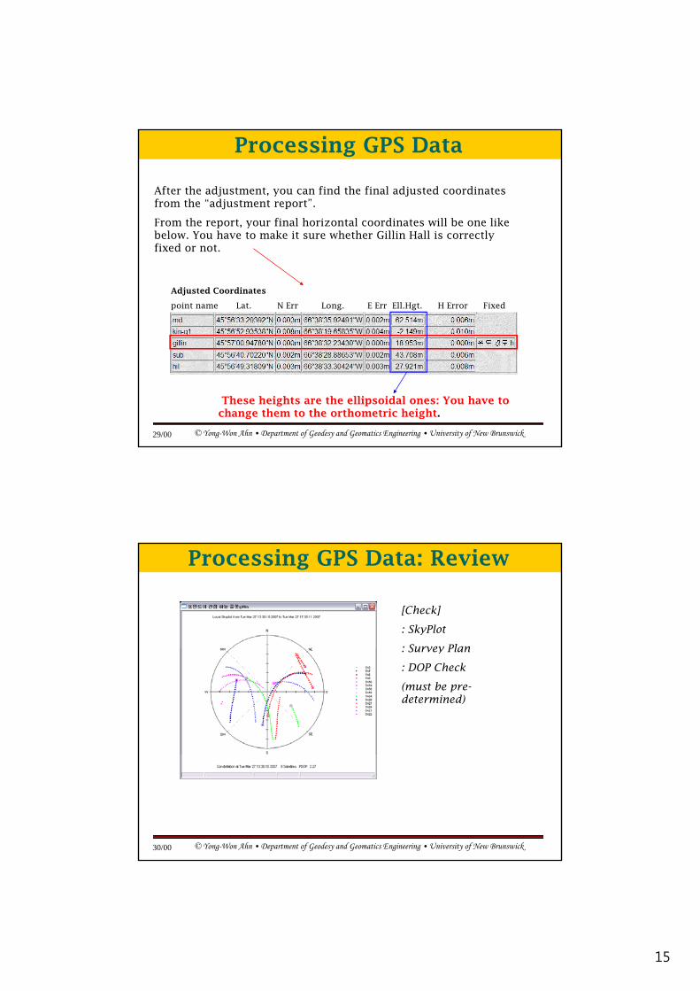
: Make a project and copy all *.dat to checkin directory.
Processing GPS DataCycle Slip Manipulation
: View Timeline
(check the time line and then decide if there’re any data to remove or not to be processed, minor!)
© Yong-Won Ahn • Department of Geodesy and Geomatics Engineering • University of New Brunswick26/00
: Cycle slip elimination (check the jumps and deactivate those)
14
GPS Network Adjustment: Fixed Control Point
: Bring all GPS data
: Check the antenna height or put the correct APC of the antenna
Processing GPS Data
: Click Process button (will take time)
: Baselines can be seen (as white line) in TGO™
: Adjustment will be done by selecting the baselines that make a triangle network
: Selected and then click the Adjust button
: Report Network Adjustment Report
© Yong-Won Ahn • Department of Geodesy and Geomatics Engineering • University of New Brunswick27/00
: Report Network Adjustment Report
: Analysis the results
Note: Fixed Point (Gillin Hall): From GPS Lab.
(Applied to TGO and adjusted based on this)
Gillin Hall (NAD83 CSRS)
Lat: 45 57 0.9478
Lon: 66 38 32.2343
Hgt: 18.362 m
gate
After processed the baseline successfully, go to Adjustment. Check
Processing GPS Data
Adjust to NAD 1983 (Canada)
Adjustment Points you must fix “Gillen Hall” with the coordinates
© Yong-Won Ahn • Department of Geodesy and Geomatics Engineering • University of New Brunswick28/00
coordinates provided.
Adjustment Adjustment (F10)
15
After the adjustment, you can find the final adjusted coordinates from the “adjustment report”.
From the report, your final horizontal coordinates will be one like below You have to make it sure whether Gillin Hall is correctly
Processing GPS Data
below. You have to make it sure whether Gillin Hall is correctly fixed or not.
Adjusted Coordinates
point name Lat. N Err Long. E Err Ell.Hgt. H Error Fixed
© Yong-Won Ahn • Department of Geodesy and Geomatics Engineering • University of New Brunswick29/00
These heights are the ellipsoidal ones: You have to change them to the orthometric height.
[Check]
: SkyPlot
: Survey Plan
Processing GPS Data: Review
: Survey Plan
: DOP Check
(must be pre-determined)
© Yong-Won Ahn • Department of Geodesy and Geomatics Engineering • University of New Brunswick30/00
16
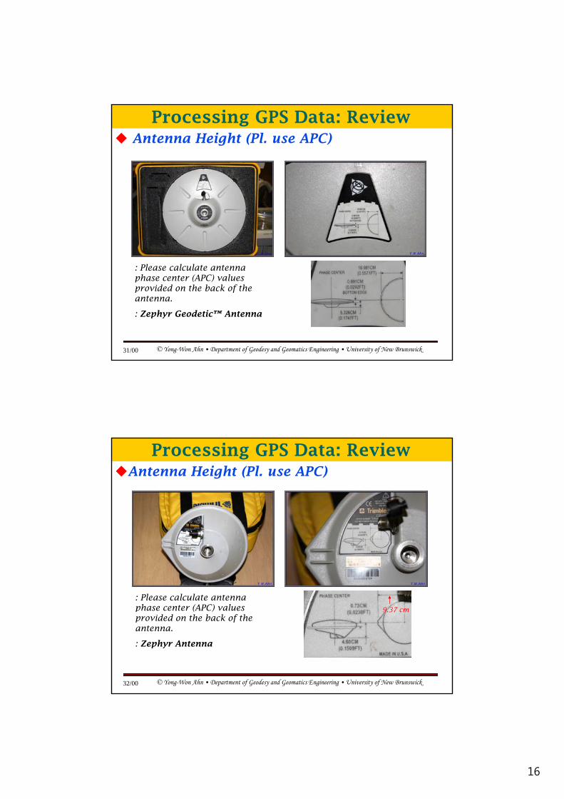
Antenna Height (Pl. use APC)
Processing GPS Data: Review
: Please calculate antenna h t (APC) l
© Yong-Won Ahn • Department of Geodesy and Geomatics Engineering • University of New Brunswick31/00
phase center (APC) values provided on the back of the antenna.
: Zephyr Geodetic™ Antenna
Antenna Height (Pl. use APC)
Processing GPS Data: Review
: Please calculate antenna phase center (APC) values 9 37
© Yong-Won Ahn • Department of Geodesy and Geomatics Engineering • University of New Brunswick32/00
phase center (APC) values provided on the back of the antenna.
: Zephyr Antenna
9.37 cm
17
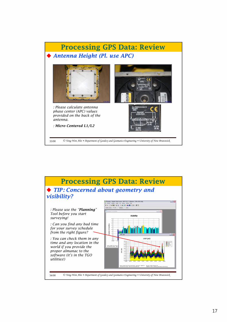
Antenna Height (Pl. use APC)
Processing GPS Data: Review
: Please calculate antenna phase center (APC) values
© Yong-Won Ahn • Department of Geodesy and Geomatics Engineering • University of New Brunswick33/00
phase center (APC) values provided on the back of the antenna.
: Micro Centered L1/L2
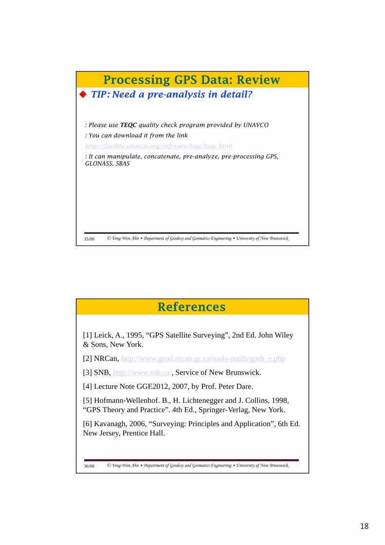
TIP: Concerned about geometry and visibility?
: Please use the “Planning”
Processing GPS Data: Review
: Please use the Planning Tool before you start surveying!
: Can you find any bad time for your survey schedule from the right figure?
: You can check them in any time and any location in the
© Yong-Won Ahn • Department of Geodesy and Geomatics Engineering • University of New Brunswick34/00
world if you provide the proper almanac to the software (it’s in the TGO utilities!)
18
TIP: Need a pre-analysis in detail?
: Please use TEQC quality check program provided by UNAVCO
Processing GPS Data: Review
: You can download it from the link
http://facility.unavco.org/software/teqc/teqc.html
: It can manipulate, concatenate, pre-analyze, pre-processing GPS, GLONASS, SBAS
© Yong-Won Ahn • Department of Geodesy and Geomatics Engineering • University of New Brunswick35/00
[1] Leick, A., 1995, “GPS Satellite Surveying”, 2nd Ed. John Wiley & Sons, New York.
[2] NRC htt // d /t l til / h h
References
[2] NRCan, http://www.geod.nrcan.gc.ca/tools-outils/gpsh_e.php
[3] SNB, http://www.snb.ca/, Service of New Brunswick.
[4] Lecture Note GGE2012, 2007, by Prof. Peter Dare.
[5] Hofmann-Wellenhof. B., H. Lichtenegger and J. Collins, 1998, “GPS Theory and Practice”. 4th Ed., Springer-Verlag, New York.
© Yong-Won Ahn • Department of Geodesy and Geomatics Engineering • University of New Brunswick36/00
[6] Kavanagh, 2006, “Surveying: Principles and Application”, 6th Ed. New Jersey, Prentice Hall.
19
Earth-Centered Earth-Fixed (ECEF) Coordinate System
– For the purpose of computing the position of a GPS Receiver
• Rotate with the Earth
WGS84 System
• The Characteristics of ECEF
– Originate at the center of the Earth
– xy-plane : coincide with the Earth’s equatorial plane– +x-axis : Point in the direction of 0° longitude
– +y-axis : 90° E longitude
– +z-axis : Normal to the equatorial plane in the direction
of the geographical north pole
© Yong-Won Ahn • Department of Geodesy and Geomatics Engineering • University of New Brunswick37/00
• The satellite position & velocity vectors must be available in the ECEF for GPS navigation problem
• In the case of GPS positioning, Cartesian coordinates (X,Y,Z) of the user’s receiver are computed
World Geodetic System (WGS84 )– Standard physical model of the Earth for GPS
• The Characteristics of WGS84
Originate at the center of the Earth
WGS84 System
– Originate at the center of the Earth
– a : 6378.137 km = Mean equatorial radius
– b : 6,356.7523142 km
– e : Eccentricity of Earth Ellipsoid = 0.0818
– c : speed of light = 299,792.458 km/s
– f : flattening = 1 - b/a
– e’ : second eccentricity = eb/a
0 0820944379496
© Yong-Won Ahn • Department of Geodesy and Geomatics Engineering • University of New Brunswick38/00
= 0.0820944379496

20
Geodetic Coordinates System
– ECEF coordinate with the reference ellipsoid (for example WGS84) called Geodetic coordinate
• So called Geographic coordinate system
WGS84 System
g p y
– Geodetic longitude (λ)• The angle between the user and the x-axis measured in the
xy-plane
– Geodetic latitude (φ )• The angle between the ellipsoid normal vector & projection
of it into the equatorial plane
– Geodetic height(h)
© Yong-Won Ahn • Department of Geodesy and Geomatics Engineering • University of New Brunswick39/00
– Geodetic height(h)• Relative to the WGS84 ellipsoid not to the geoid• Minimum distance between the user and the reference
ellipsoid(i.e. ellipsoid normal)
GPS HeightHeight
- Geodetic (Ellipsoidal) Height; h
: The height above the ellipsoid. Ellipsoidal height is geometric, not a physical parameter and is what is given by the GPS technique.
- Orthometric Height; H
: The height above MSL. Orthometric height is a physical parameter and is what is given by most conventional surveying techniques. It is the level surface that a body of water will conform to. In this section (H) is obtained using the GPS observed ellipsoidal height (h) and correcting it with the Geoid/Ellipsoid separation (N) and the geoid model. For all pillar type HPN this value can be compared with the leveled height.
© Yong-Won Ahn • Department of Geodesy and Geomatics Engineering • University of New Brunswick40/00

21
- Geoid ellipsoidal separation (N):
: Is the distance between the ellipsoid and geoid at a specific point and is also known as the Geoid Undulation. The separation added to the orthometric (sea level) height (H), results in the ellipsoid height (h). The following formulae is of
Height
GPS Height
particular importance with the use of GPS.
h = H + N
where
h = is the ellipsoidal height
(height usually obtained with GPS)
© Yong-Won Ahn • Department of Geodesy and Geomatics Engineering • University of New Brunswick41/00
H = is the orthometric height (sea-level)
N = is the geoid ellipsoidal separation
GPS-H:
• GPS Height Transformation Packages.
Height
GPS Height
•http://www.geod.nrcan.gc.ca/tools-outils/gpsh_e.php
• Online or Offline programs are provided. Offline program, called “gpsh-e.zip” released on Nov. 2001,
© Yong-Won Ahn • Department of Geodesy and Geomatics Engineering • University of New Brunswick42/00
is Win16 environment. Please check your computer to install it.
22
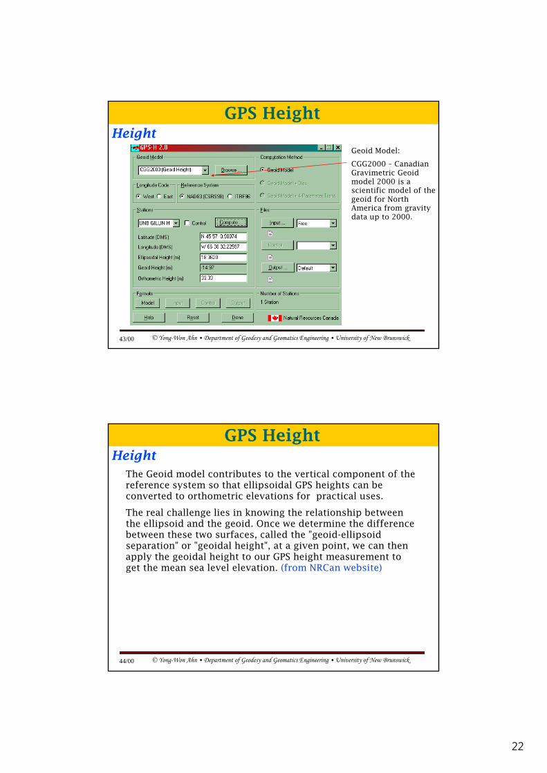
HeightGeoid Model:
CGG2000 – Canadian Gravimetric Geoid model 2000 is a
GPS Height
model 2000 is a scientific model of the geoid for North America from gravity data up to 2000.
© Yong-Won Ahn • Department of Geodesy and Geomatics Engineering • University of New Brunswick43/00
The Geoid model contributes to the vertical component of the reference system so that ellipsoidal GPS heights can be converted to orthometric elevations for practical uses.
Height
GPS Height
The real challenge lies in knowing the relationship between the ellipsoid and the geoid. Once we determine the difference between these two surfaces, called the "geoid-ellipsoid separation" or "geoidal height", at a given point, we can then apply the geoidal height to our GPS height measurement to get the mean sea level elevation. (from NRCan website)
© Yong-Won Ahn • Department of Geodesy and Geomatics Engineering • University of New Brunswick44/00
23
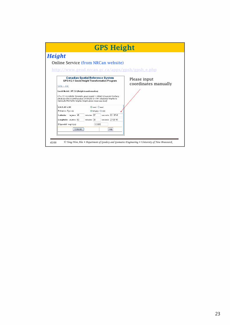
Online Service (from NRCan website)
http://www.geod.nrcan.gc.ca/apps/gpsh/gpsh_e.php
Height
GPS Height
Please input coordinates manually
© Yong-Won Ahn • Department of Geodesy and Geomatics Engineering • University of New Brunswick45/00
Related Documents