MAN08100418E A00420-1E Advantage ™ 2E Getting Started 8.0

Welcome message from author
This document is posted to help you gain knowledge. Please leave a comment to let me know what you think about it! Share it to your friends and learn new things together.
Transcript

MAN08100418EA00420-1E
Advantage ™ 2E
Getting Started8.0

A2GSG800.doc, printed on 9/3/2002, at 3:56 PM
This documentation and related computer software program (hereinafter referred to as the “Documentation”) is for the end user’s informational purposes only and is subject to change or withdrawal by Computer Associates International, Inc. (“CA”) at any time.
This documentation may not be copied, transferred, reproduced, disclosed or duplicated, in whole or in part, without the prior written consent of CA. This documentation is proprietary information of CA and protected by the copyright laws of the United States and international treaties.
Notwithstanding the foregoing, licensed users may print a reasonable number of copies of this documentation for their own internal use, provided that all CA copyright notices and legends are affixed to each reproduced copy. Only authorized employees, consultants, or agents of the user who are bound by the confidentiality provisions of the license for the software are permitted to have access to such copies.
This right to print copies is limited to the period during which the license for the product remains in full force and effect. Should the license terminate for any reason, it shall be the user’s responsibility to return to CA the reproduced copies or to certify to CA that same have been destroyed.
To the extent permitted by applicable law, CA provides this documentation “as is” without warranty of any kind, including without limitation, any implied warranties of merchantability, fitness for a particular purpose or noninfringement. In no event will CA be liable to the end user or any third party for any loss or damage, direct or indirect, from the use of this documentation, including without limitation, lost profits, business interruption, goodwill, or lost data, even if CA is expressly advised of such loss or damage.
The use of any product referenced in this documentation and this documentation is governed by the end user’s applicable license agreement.
The manufacturer of this documentation is Computer Associates International, Inc.
Provided with “Restricted Rights” as set forth in 48 C.F.R. Section 12.212, 48 C.F.R. Sections 52.227-19(c)(1) and (2) or DFARS Section 252.227-7013(c)(1)(ii) or applicable successor provisions.
2002 Computer Associates International, Inc.
All trademarks, trade names, service marks, and logos referenced herein belong to their respective companies.

A2GSG800.doc, printed on 9/3/2002, at 3:56 PM
Contents
Chapter 1: Concepts and Features Welcome!..................................................................... 1-1
The Purpose Of This Guide................................................. 1-1 CA Services: Enabling Solutions Through Experience ......................... 1-2 CA Education Services ..................................................... 1-2 Computer Associates: The Software That Manages eBusiness .................. 1-3 For More Information...................................................... 1-3
Overview of Advantage 2E..................................................... 1-3 Advantage 2E Objectives ................................................... 1-4
Design Principles.............................................................. 1-5 Data-Driven Design ....................................................... 1-5 Object-Based Design ....................................................... 1-6
The Application Development Life Cycle ........................................ 1-7 Rapid Prototyping Methodology............................................ 1-7 Maintaining Applications .................................................. 1-8
Features and Capabilities ...................................................... 1-9 Change Control Facilities..................................................1-11 Cross Reference Facilities..................................................1-11 Change Management .....................................................1-12 Technical Documentation .................................................1-12 National Language Support (NLS) .........................................1-13 Integrating With Existing Databases and Applications .......................1-14
Contents iii

A2GSG800.doc, printed on 9/3/2002, at 3:56 PM
Chapter 2: Components and Installation Advantage 2E Product Libraries................................................ 2-1 Advantage 2E Development Environment ...................................... 2-3
The Model Library ........................................................ 2-4 Generation Library........................................................ 2-4 SQL Collection............................................................ 2-4
Installing Advantage 2E ....................................................... 2-6 Upgrading Advantage 2E ..................................................... 2-6
Chapter 3: Usability Tour Setup ........................................................................ 3-1 Initial Analysis ............................................................... 3-3
Entering the Design Model................................................. 3-4 The Display Services Menu ................................................ 3-7 Leaving the Design Model ................................................. 3-8
Prototyping an Application .................................................... 3-8 Creating Prototype Panels ................................................. 3-9 Naming Prototype Panels................................................. 3-10 Using Advantage 2E Device Design Animation ............................. 3-10 Converting an Advantage 2E Device Design to 400 Toolkit................... 3-12 Converting Multi-screen Functions ........................................ 3-13 Replacing 400 Toolkit Navigation and Data................................. 3-13 Transferring Control to 400 Toolkit ........................................ 3-14 Working with a 400 Toolkit Panel Design .................................. 3-14 Editing the Panel......................................................... 3-16 Defining Command Keys ................................................. 3-16 Building a Window Prototype............................................. 3-16 Building an Action Bar Prototype.......................................... 3-17 Defining Color........................................................... 3-19 Entering Sample Data .................................................... 3-23 Displaying Prototype Panels .............................................. 3-23 Returning to Advantage 2E ............................................... 3-24
iv Getting Started

A2GSG800.doc, printed on 9/3/2002, at 3:56 PM
Data Modeling ...............................................................3-25 Enter Relations ...........................................................3-26 Define Objects............................................................3-27 File Entries...............................................................3-28 Documenting Relations ...................................................3-29 Field Details and Conditions...............................................3-30 Relationship Extension....................................................3-33 Virtual Fields ............................................................3-34
Defining Access Paths ........................................................3-36 Default Access Paths......................................................3-36 View Default Access Paths ................................................3-37
Designing Functions..........................................................3-39 Default Reference File Functions ...........................................3-39 New Functions ...........................................................3-41 Displaying Functions .....................................................3-43 Function Options .........................................................3-44 Linking Functions ........................................................3-45 Default Panels............................................................3-48 Default Action Diagram...................................................3-51
Generating Source Code ......................................................3-52 Generate Access Paths ....................................................3-52 Generate External Functions Source Code...................................3-55
Generating and Creating Compiled Objects.....................................3-56 Testing Your Programs....................................................3-58
Contents v


A2GSG800.doc, printed on 9/3/2002, at 3:56 PM
Chapter
1 Concepts and Features
Welcome! Congratulations! You’ve chosen Advantage 2E (formerly known as COOL:2E) to assist you in your iSeries (AS/400) software development efforts.
Advantage 2E is an application development tool for the iSeries (AS/400). It provides a complete range of interactive facilities to design, generate, document, and maintain applications software. Advantage 2E includes Advantage 2E 400 Toolkit, a set of implementation support and system utilities incorporating menu creation, object management tools, and a full range of automated technical documentation facilities.
The Purpose Of This Guide
This is your starting point to familiarity with Advantage 2E in the following areas:
■ Features
■ Components
■ Installation
■ Ease of Use
Concepts and Features 1–1

Welcome!
A2GSG800.doc, printed on 9/3/2002, at 3:56 PM
By the time you have finished reading this guide, you will have an overview of the wide scope of the product and how to use it. We want you to feel comfortable with Advantage 2E as you begin to use it.
CA Services: Enabling Solutions Through Experience
When it comes to getting on the information fast track, CA Services can recommend and install a full suite of portal and knowledge management solutions to keep your business moving. Our associates offer the proprietary know-how on custom-fitting your enterprise for solutions ranging from life cycle management to data warehousing to next-level business intelligence. Our experts will leave you with the technology and knowledge tools to fully collect, exploit, and leverage your data resources and applications.
CA Education Services
Computer Associates Global Education Services (CA Education) offerings include instructor-led and computer-based training, product certification programs, third-party education programs, distance learning, and software simulation. These services help to expand the knowledge base so you are better able to use our products more efficiently, contributing to your greater success. CA Education has been developed to assist today’s technologists in everything from understanding product capabilities to implementation and quality performance.
Because the vast community of education seekers is varied, so too are our methods of instruction. CA Education is committed to provide a variety of alternatives to traditional instructor-led training, including synchronous and asynchronous distance learning, as well as Unicenter simulation.
For training that must be extended to a wider audience—for a fraction of the cost and logistical hassle of sending everybody away to a class—CA Education offers excellent distance learning options.
1–2 Getting Started

Overview of Advantage 2E
A2GSG800.doc, printed on 9/3/2002, at 3:56 PM
Computer Associates: The Software That Manages eBusiness
The next generation of eBusiness promises unlimited opportunities by leveraging existing business infrastructures and adopting new technologies. At the same time, extremely complicated management presents challenges—from managing the computing devices to integrating and managing the applications, data, and business processes within and across organizational boundaries. Look to CA for the answers.
CA has the solutions available to help eBusinesses address these important issues. Through industry-leading eBusiness Process Management, eBusiness Information Management, and eBusiness Infrastructure Management offerings, CA delivers the only comprehensive, state-of-the-art solutions, serving all stakeholders in this extended global economy.
For More Information
After walking through this Getting Started, you can refer to the numerous resources available to you for additional information. Your product CD contains useful instructional documents that showcase your software and provide detailed explanations about the product’s comprehensive, feature-rich components. In addition, the online help system at esupport.ca.com offers procedural information and answers to any questions you may encounter.
Overview of Advantage 2E Advantage 2E is an application development tool that allows you to design, develop, implement, and maintain applications software more efficiently, more rigorously, and more effectively than third generation methods permit. Using Advantage 2E, you can create programs without having to know a programming language. These programs form your applications that manipulate your data according to your business requirements.
Concepts and Features 1–3

Overview of Advantage 2E
A2GSG800.doc, printed on 9/3/2002, at 3:56 PM
An application development tool is more than just a program generator. It helps you determine how your business or organization can be best represented on a computer with respect both to the data that you need to store and to the functions that operate upon the data. Advantage 2E's data modeling and procedural specification facilities enable you to do precisely this. In other words, your application is stored as business design objects, such as data definitions, interface designs, and action diagrams.
Advantage 2E Objectives
Advantage 2E incorporates a number of industry standard methodologies in application development such as entity-relationship modeling and object-based design. Although Advantage 2E is a modeling and specification tool, the end product is not just a design; it is a working application system.
Advantage 2E separates the process of design from the process of implementation. Apart from clarity, this has the following significant advantages:
■ Changes to the specification can be applied automatically throughout the application design.
■ Improvements or changes to the implementation can be made independently of the specification.
■ The same design can be used to implement applications for several different operating systems and environments.
The aim of Advantage 2E is to help and allow you to:
■ Design applications that are closer to your end user's requirements.
■ Design higher quality applications.
■ Create applications that are easy to maintain and enhance as your business evolves.
■ Design applications independently of the language in which you implement them.
1–4 Getting Started

Design Principles
A2GSG800.doc, printed on 9/3/2002, at 3:56 PM
■ Help application designers create systems that make an effective use of the architecture for which they are targeted.
■ Enable you to design and generate applications many times faster than traditional methods.
Design Principles Advantage 2E's approach to the design of application systems embodies important design concepts:
■ Data-driven design
■ Object-based design
Each of these concepts is described briefly in the sections that follow.
Data-Driven Design
The prerequisite of a successful system design is a correctly designed database. If the application data can be defined and described in a careful, organized manner, it is possible to streamline the creation of processing functions that work with that information. To produce a correct database you need to be rigorous in the analysis of the data you want to store in the system. This can be achieved through relational database design.
Traditional application development has often been a process-driven approach in which the structure of the data is imposed by the processing of each program. Updating the database for business environment changes is difficult since manual checking could be required to ensure consistency.
Concepts and Features 1–5
Design Principles
A2GSG800.doc, printed on 9/3/2002, at 3:56 PM
Within a data-driven design, the business model of your application is held in the data model, enabling database integrity from the outset. Changes to this central design automatically cascade throughout the application design.
For more information on data-driven design, see Data Modeling.
Object-Based Design
One of the key concepts of the OS/400 operating system is the Object, upon which actions are performed. Objects provide the following:
■ A mechanism for modularization. Details of how a process is implemented can be separated from the purpose of the process.
■ A way to describe software entities that is easily understood.
At a basic level most languages have a verb-object syntax. We tend to think in such terms as Add a Customer or Send an Invoice. Advantage 2E incorporates this natural language syntax into the design process. The resulting design is expressed in terminology that is easily understood by both the designer and the end users.
Advantage 2E's design provides for this object-based approach. This design concept is incorporated in Advantage 2E where the objects are database entities and the actions are Advantage 2E functions. These functions specify a system in terms of simple processes operating on entities, independently of how the processes are implemented.
Advantage 2E focuses on reusable components. Actions and objects are defined once and reused. For example, a subroutine to update a record is defined once. All functions that update records can use this common routine.
1–6 Getting Started

The Application Development Life Cycle
A2GSG800.doc, printed on 9/3/2002, at 3:56 PM
The Application Development Life Cycle The design principles Advantage 2E uses are applied throughout the life cycle of application development, including all of the tasks required to start, complete, and maintain an application. Advantage 2E supports a structured, data-driven approach in the application development life cycle.
To help eliminate errors and misunderstandings, Advantage 2E provides a structured notation that can be interpreted accurately.
Advantage 2E captures and describes application specifications, which reflect user's requirements. Once the requirements are represented by the design model and agreed to by the users, the other tasks in the life cycle will use this information to ensure the efficient development of the application.
Rapid Prototyping Methodology
Rapid Prototyping Methodology (RPM) is one approach to using Advantage 2E in the application development process. Advantage 2E RPM is a data-driven, pragmatic approach to rapid application creation that provides a framework for using Advantage 2E to swiftly build quality systems. The Advantage 2E RPM life cycle is divided into the following four phases. User involvement is critical at all stages.
■ Analyze—begin system analysis, complete entity relationship diagram, complete Advantage 2E data model, design primary access paths, function flows, and device designs
■ Design—continue development, prototype application, review with user, update design, continue functions definition, action diagrams, and complete database design.
■ Construct—generate final version of application and complete unit testing.
■ Implement—complete integration test, system test, and user acceptance test. Convert system.
Concepts and Features 1–7
The Application Development Life Cycle
A2GSG800.doc, printed on 9/3/2002, at 3:56 PM
The Advantage 2E toolset automates many of the traditionally manual, error-prone design and coding processes. The features and capabilities of Advantage 2E are the driving forces behind Advantage 2E RPM.
Maintaining Applications
To modify an application you can change your design model as necessary, revisit any function designs which need to take account of the changes and regenerate all elements dependent on the changes to the files. This structured approach is crucial to realizing your investment in Computer Aided Software Engineering (CASE).
For instance, let us say that you want to add a field to a file. Advantage 2E will automatically add the field to all the necessary access paths (except for those you have earmarked as being unalterable) and make it available on all of the device designs dependent on the access paths. You can use the panel and report design tools to place the field where you want it on these existing designs. The appropriate logic will be added to the function to handle referential integrity checking where appropriate.
You can assess the implications of the changes using interactive inquiries as well as the model documentation reports.
In most cases, regeneration becomes a routine matter. Using Advantage 2E's batch generation facilities, it is possible to have an entire system regenerate itself to take account of a database modification. For example, when a field is used in a function, the function keeps a reference to the field that is resolved when the function is generated. If you make a change, such as to the length of the field, it is reflected within the function's program logic and panel or report design when you next generate the function. This unique feature of Advantage 2E allows a massive reduction in the maintenance of Advantage 2E-generated applications.
1–8 Getting Started

Features and Capabilities
A2GSG800.doc, printed on 9/3/2002, at 3:56 PM
Features and Capabilities Advantage 2E allows you to design, develop, implement, and maintain applications software for the iSeries (AS/400) efficiently and effectively.
Advantage 2E includes the following features:
■ Entity Relationship Specification
– Automatic creation of a data dictionary
– Support for free-format text to describe any of the design objects for both designers and end users
– Automatic documentation of the design model
– Specification of domain checks
■ Access Paths
– Design of logical views to support functions
– Retrieval of existing OS/400 database descriptions
■ Functions
– Automatic creation of action diagram and panel or report design
– Modular (object-based) design
– Procedural specification through reusable components and action diagrams
■ Panels and Reports
– Automatic design of panel and report layouts combined with interactive device painting facilities
– Panel design prototyping facilities
– Automatic provision of SAA Common User Access design standards
Concepts and Features 1–9

Features and Capabilities
A2GSG800.doc, printed on 9/3/2002, at 3:56 PM
■ HLL code generation
– Generation of Digital Data Storage (DDS) source or Structured Query Language (SQL) data definition language for the database
– Generation of source code for panels and reports
– Generation of source code (RPG or COBOL) for iSeries (AS/400) stand-alone programs
– Generation of source code (RPG or COBOL) for the client server portion of client server pairs
– Generation of Micro Focus COBOL code for the client portion of client server pairs
– Automatic generation of help text
■ Other features
– Automatic implementation of object naming standards
– Automatic implementation of panel design standards
– Automated change control of design objects, including change tracking, multi-level impact analysis, model object lists, and function versioning
– Automated documentation of generated systems
– Cross reference facilities
– Integration of user source code within generated functions
– Regeneration of source code if the model is changed with the preservation of user modifications to the processing specifications
– Integration of the native facilities of OS/400 for commitment control, journaling, and error handling
– Generation of code quickly and easily when the design is changed
– Automatic generation of referential integrity checks and domain checking
1–10 Getting Started
Features and Capabilities
A2GSG800.doc, printed on 9/3/2002, at 3:56 PM
■ Documentation features
– Online help text
– Extensive technical documentation
Change Control Facilities
Advantage 2E change control facilities are a set of features and functions supplied with Advantage 2E for managing Advantage 2E design objects. They include the following:
■ Capability of building lists of Advantage 2E design objects, known as model object lists, for auditing and input to specialized model list commands
■ Impact analysis tools, including component change processing
■ Model object cross-reference facilities
■ Support for versions of functions and messages
■ Redirection of functions and messages
■ Copying model objects between models
■ Centrally recorded model object information
You can use the change control facilities as follows:
■ As tools to work with and manage your Advantage 2E design objects
■ To manually control changes to your design model
■ With Advantage 2E Change Management to provide an integrated, automated change management solution
Cross Reference Facilities
Advantage 2E has a number of facilities to help you identify dependencies between Advantage 2E model objects. These can be of use when you need to identify the object affected by a particular change.
Concepts and Features 1–11

Features and Capabilities
A2GSG800.doc, printed on 9/3/2002, at 3:56 PM
Change Management
Advantage 2E Change Management (CM) automates control of changes to Advantage 2E design objects and generated applications. CM tracks and controls changes from development to production, enabling impact analysis, concurrent development, and rigorous promotion of objects.
For more information on change management, see the Advantage 2E Change Management User Guide.
Technical Documentation
You can produce documentation for Advantage 2E models using documentation commands or by following the standard self-documenting procedures.
Documenting a Model Using Commands
You can invoke the commands using the Advantage 2E Display Services Menu or you can call them directly by using the appropriate Advantage 2E command. The documentation commands can be used on individual objects or groups of objects such as all functions for a file.
Each of the documentation commands has one or more selection parameters with which you can specify the following:
■ The selection criteria to identify the Advantage 2E objects in the model you want to document
■ The print options with which you can specify what information you want listed for the selected design objects
1–12 Getting Started

Features and Capabilities
A2GSG800.doc, printed on 9/3/2002, at 3:56 PM
Documenting an Application
The application systems generated by Advantage 2E follow the Advantage 2E standards for producing self-documenting systems. It is therefore possible to run the 400 Toolkit documentation utilities upon the generated systems to produce documentation. Objects, members, formats, and fields all have descriptive text specified with the TEXT keyword. Generated source code automatically contains 400 Toolkit source directives to specify a title, compiler overrides, and a synopsis.
With the 400 Toolkit utilities you can create summary and cross reference documentation directly from HLL source and OS/400 objects.
National Language Support (NLS)
There are French (national and multinational) and Japanese localized versions of Advantage 2E. These non-English versions provide a French or Japanese developer interface.
Developers can also generate versions of applications that place one of many other languages in the user interface. The default components, such as help text and function keys, can be generated in one of a number of languages. This is done either as part of the generated application or with language independent message files.
Generated Application Language Support
With this option your application modules and components contain hard coded text messages in a selected language. This allows you to build different versions of your applications for different nationalities.
Concepts and Features 1–13

Features and Capabilities
A2GSG800.doc, printed on 9/3/2002, at 3:56 PM
Language Independent Support
Advanced NLS allows your generated applications to be language independent by removing hard coded constants from panels and reports and placing them in message files. These message files can then be translated into several languages with the appropriate language resolved at execution time. This allows a single set of generated programs and panels to support multiple languages at execution time.
Note: Executing DBCS and ideographic versions requires a DBCS OS/400 system.
Integrating With Existing Databases and Applications
Descriptions of existing OS/400 physical files can be retrieved into an Advantage 2E data model with a process called assimilation. You can add extra relations and define access paths and functions for assimilated files in the same way that you would with other model files.
The three possible approaches to assimilating an existing database include:
■ Assimilation as is—The existing database is preserved exactly as it is.
■ Assimilation with limited modifications—The data model implied by the database is preserved, but is normalized or corrected where appropriate.
■ Full assimilation—The data model implied by the existing database is used as a starting point for a new, normalized model.
1–14 Getting Started

Features and Capabilities
A2GSG800.doc, printed on 9/3/2002, at 3:56 PM
Assimilating database files allows you to develop new functions and access paths over an existing database defined outside of Advantage 2E. It also saves you from having to re-key all of the field names and attributes into your model or having to identify individual fields as you use them on a program-by-program basis.
For more information on assimilation, see Data Modeling.
Concepts and Features 1–15


A2GSG800.doc, printed on 9/3/2002, at 3:56 PM
Chapter
2 Components and Installation
This chapter describes the libraries that make up Advantage 2E and the development environment. This chapter also outlines the installation and upgrade process and introduces the 400 Toolkit prototyping facilities.
Advantage 2E Product Libraries The Advantage 2E product libraries contain the files and objects needed to use Advantage 2E products. The product libraries include the Advantage 2E base product library (Y2SY) and 400 Toolkit base product library (Y1SY). All Advantage 2E object names begin with the letter Y.
In addition to Y2SY and Y1SY, Advantage 2E ships base product libraries that contain the appropriate default national language libraries, the HLL source generators, the Advantage 2E null model, and a library containing some Advantage 2E source.
Note: At many sites, only Y1SY, Y2SY, Y2SYMDL, and Y2SYSRC are listed on the machine. The remaining libraries were merged into the base product libraries at the time of installation.
Components and Installation 2–1

Advantage 2E Product Libraries
A2GSG800.doc, printed on 9/3/2002, at 3:56 PM
The following table provides a complete list of the Advantage 2E product libraries:
Ship Name
Library or Folder
Suggested Restore Library or Folder
Y1SY 400 Toolkit base Y1SY
Y1SYVnll1 400 Toolkit LDOs Y1SY
Y2SY Advantage 2E base Y2SY
Y2SYVnll1 Advantage 2E LDOs Y2SY
Y2SYMDL Advantage 2E null model Y2SYMDL
Y2SYCBL Advantage 2E COBOL generators
Y2SYCBL
Y2SYRPG Advantage 2E RPG generators
Y2SY
Y2SYSRC Advantage 2E source Y2SYSRC
YLUSLIB0 Advantage 2E Security Library
YLUSLIB2
1 nll refers to the national language, for example, Spanish (ESP) or English (ENG). 2 The Advantage 2E Security Library must be restored to the YLUSLIB library.
2–2 Getting Started

Advantage 2E Development Environment
A2GSG800.doc, printed on 9/3/2002, at 3:56 PM
The supplied source for Advantage 2E resides in source files in the Y2SYSRC library. The source for 400 Toolkit resides in the Y1USRSRC file in the Y1SY library. You can obtain a list of these members with the OS/400 Work with Members Using PDM (WRKMBRPDM) command.
The YCRLUSLIB command that runs during product installation automatically updates or creates the YLUSLIB library.
Advantage 2E Development Environment The Advantage 2E development environment is the model in which the development team creates the application objects and in which initial generation takes place. The development environment is also where these objects are tested individually to determine whether they function correctly and efficiently.
Advantage 2E models must reside in a single library called the model library. Each model must also have a generation library associated with it. Models and generation libraries might also be associated with SQL collections. The collection is a separate library similar to the generation library.
ModelLibrary
GenerationLibrary
SQLCollection
Source FilesCompiled ProgramsAccess Paths (DDS)Journals
FilesJournalsData DictionariesAccess Paths (SQL)
Components and Installation 2–3

Advantage 2E Development Environment
A2GSG800.doc, printed on 9/3/2002, at 3:56 PM
The Model Library
Each model library holds the database files that make up the model. The associated generation library contains the source Advantage 2E generates for the model and the compiled objects from that source. The model library and the generation library should be regarded as a pair. The model library also contains other necessary OS/400 objects and an Advantage 2E job description. If the developer generates SQL, the model library also refers to SQL collections.
The Create Model Library (YCRTMDLLIB) command creates the libraries that compose a model.
For more information about the YCRTMDLLIB command, see the Advantage 2E Command Reference.
Generation Library
The generation library holds Advantage 2E generated source, compiled objects, and help text. You can move generated objects from the generation library to any other library. And you can move the generation library to an environment that does not contain Advantage 2E product libraries.
SQL Collection
Advantage 2E lets you use SQL in place of or along with DDS in data definition statements. Using SQL you define tables, views, rows, and columns, rather than iSeries (AS/400) physical files, logical files, records, and fields.
You can implement SQL at both the system level and the model level. If you implement SQL at the system level, all new models default to SQL. When you implement at the model level, all access paths and functions default to SQL. Within a model, you can also specify SQL for individual access paths and functions.
2–4 Getting Started

Advantage 2E Development Environment
A2GSG800.doc, printed on 9/3/2002, at 3:56 PM
The OS/400 operating system contains the execution objects necessary to execute applications you generate with SQL. However, if you want to generate and compile Advantage 2E applications that use SQL, you must have IBM’s SQL/400 program products installed and the QSQL library loaded on your iSeries (AS/400).
To use SQL in a model environment, SQL collections, equivalent to iSeries (AS/400) libraries, must be associated with the model library. The YCRTMDLLIB command can automatically create the SQL collection. This command includes the SQLLIB parameter that lets you create the collection for a particular model.
You can create SQL collections for an existing model with the Create SQL Library (YCRTSQLLIB) command. This command updates the YSQLLIB model value for the associated model. You then use the Change Model Value (YCHGMDLVAL) command to update the YDBFGEN model value to SQL.
For more information about:
■ The YCRTSQLLIB and YCHGMDLVAL commands, see the Advantage 2E Command Reference
■ Differences between earlier versions of Advantage 2E SQL implementations and current implementations, see the SQL Implementation appendix in the Advantage 2E Administrator Guide
■ IBM’s Structured Query Language, see your IBM documentation
Components and Installation 2–5
Installing Advantage 2E
A2GSG800.doc, printed on 9/3/2002, at 3:56 PM
Installing Advantage 2E If you are a new user, you must load the Advantage 2E and 400 Toolkit products onto your system before you can use Advantage 2E.
The Advantage 2E Installation Guide provides detailed information about the entire installation process. These instructions:
■ List the prerequisites that must be fulfilled before you install
■ Break down each step of the installation into a step-by-step procedure
■ Describe the post-load activities you carry out in order to customize the product for your system
Before you begin the installation, make sure you read these instructions to familiarize yourself with the process.
Upgrading Advantage 2E New releases may include modifications that must be applied to each design model before you can use new features to work with a model. The Apply Model Change (YAPYMDLCHG) command updates one or all named Advantage 2E design models with those changes.
The Advantage 2E Installation Guide provides detailed information about upgrading to a new version of Advantage 2E. Before you begin the upgrade, make sure you read these instructions to familiarize yourself with the process.
For more information about the YAPYMDLCHG command, see the Advantage 2E Command Reference.
2–6 Getting Started

A2GSG800.doc, printed on 9/3/2002, at 3:56 PM
Chapter
3 Usability Tour
This chapter provides a quick tour of Advantage 2E. It highlights some of the features while navigating through some typical functions. As you proceed through this chapter you will preview many of the steps in sequence that you will perform when you develop your applications with Advantage 2E.
Use this chapter as an introduction to other more detailed Advantage 2E guides such as:
■ Installation Guide
■ Tutorial
■ Administrator Guide
Setup The following conditions must be met before beginning Advantage 2E development:
■ Installation—Advantage 2E must be installed on your iSeries (AS/400).
■ Authorization—You must be signed on an iSeries (AS/400) with a user profile that is authorized to use Advantage 2E and perform programming operations.
■ Library List—Your library list must include certain libraries. See the Advantage 2E Installation Guide for specific details.
Usability Tour 3–1

Setup
A2GSG800.doc, printed on 9/3/2002, at 3:56 PM
■ Design Model—A design model must be created. You can use the Create Model Library (YCRTMDLLIB) command as follows: YCRTMDLLIB MDLLIB(MYMDL) OBJPFX(MY)+ SYSTEXT(‘My Model’) DSNSTD(*CUATEXT)
In this tour of Advantage 2E, we will walk through a series of tasks that you would typically perform as an Advantage 2E user. The three major phases of development are: analyze, define, and construct. The following illustration is a high level map of the tour:
DATA MODELING
ANALYSIS and
DESIGN
ACCESS PATHS
FUNCTIONS
PROGRAM COMPILATION
CODEGENERATION Construct
Define
Analyze
3–2 Getting Started

Initial Analysis
A2GSG800.doc, printed on 9/3/2002, at 3:56 PM
Initial Analysis The following three things must be established as you begin:
DATA MODELING
ANALYSIS and
DESIGN
ACCESS PATHS
FUNCTIONS
PROGRAM COMPILATION
CODE GENERATION
■ Business requirements, based on business operations
■ Data elements, based on the business requirements
■ An entity relationship diagram (ERD)
Most of this information is obtained through discussion and analysis of the business you are working with.
The following lists show examples of the type of results you might obtain for a horse racing business. See the Advantage 2E Tutorial for more detail.
Business Requirements
A record of the Sire (father) and Dam (mother) for each horse to ensure that they are older than the horse
A record of horses entered in each race
A list of all horses including a count and total value and a list of the races each horse has entered
Data Elements
Course Name
Course Location
Course seating capacity
Horse Name
Horse Age
Horse gender
Race Name
Race Date
Usability Tour 3–3

Initial Analysis
A2GSG800.doc, printed on 9/3/2002, at 3:56 PM
These lists are examined and studied to develop an entity relationship diagram. The entity relationship diagram associates data elements with business requirements so the data can be stored in the most logical and efficient manner.
An entity is a significant item with distinct characteristics. The following is an example of some possible entities and their relations to each other:
Entity Relations
Course ■ Has one or more Races
Race ■ Is at one Course ■ Has more than one horse
Horse ■ Is in one or more races
It is often a good idea to draw a picture of the ERD rather than simply listing relations in a table. See the Advantage 2E Tutorial for more details.
Entering the Design Model
The design model facility can be started in one of the following ways:
■ Go directly to the Advantage 2E Designer (*DSNR) Menu using the Menu parameter on the Start Advantage 2E (YSTRY2) command from any OS/400 Command Entry line as follows: YSTRY2 MYMDL MENU(DSNR)
■ Bypass the Designer (*DSNR) Menu and directly enter your model for editing using the 400 Toolkit Change Library List (YCHGLIBL) command and the Edit Model (YEDTMDL) command from any OS/400 Command Entry line as follows. YCHGLIBL MYMDL YEDTMDL
3–4 Getting Started

Initial Analysis
A2GSG800.doc, printed on 9/3/2002, at 3:56 PM
The Y2 command is a short form of the YEDTMDL command. YCHGLIBL MYMDL Y2
■ Enter Advantage 2E using the Start Advantage 2E (YSTRY2) command, specifying the name of your Advantage 2E design model as the LIBLST parameter from any OS/400 Command Entry line as follows: YSTRY2 MYMDL
MAIN AS/400 Main Menu System: 2EDV1 Select one of the following: 1. User tasks 2. Office tasks 3. General system tasks 4. Files, libraries, and folders 5. Programming 6. Communications 7. Define or change the system 8. Problem handling 9. Display menu 10. Information Assistant options 11. PC Support tasks 90. Sign off Selection or command ===> ystrv2 mymdl______________________________________________ _______________________________________________________________ F3=Exit F4=Prompt F9=Retrieve F12=Cancel F13=Information Assistant F23=Set initial menu
Usability Tour 3–5

Initial Analysis
A2GSG800.doc, printed on 9/3/2002, at 3:56 PM
Next, enter 1 in the command entry line as shown in the following illustration to display the Advantage 2E Designer (*DSNR) Menu.
MAIN 2E Main Menu Level . : 1 System: 2EDV1 Select one of the following: Design Model 1. Display Designer (*DSNR) menu 2. Display Programmer (*PGMR) menu 3. Display User (*USER) menu 8. Work with Model Object Lists 9. Change to work with another model Commands 50. 2E commands in alphabetical order 51. Commands to set up or alter a model 52. Commands to copy a model 53. Commands to create an application 54. Commands to document a model More. . . Selection or command ===> _1_______________________________________________________ ______________________________________________________________ F3=Exit F6=Messages F9=Prev. request F10=Cmd Entry F14=Submitted jobs
Then, enter 1 in the command entry line as shown in the following illustration to enter your Advantage 2E design model for editing.
DSNR 2E Designer (*DSNR) Menu Level . : 2 System: 2EDV1 Select one of the following: Enter Model 1. Edit Database Relations 2. Services Menu 3. Edit Default Model Object List 4. Edit Session List (changed objects) 5. Work with Model Objects 6. Load model and display command line 8. Work with Model Object Lists 9. Change to work with another model Open Access: ? 10. Change Open Access Model Balue Enter with *NO 11. Edit Database Relations 12. Services Menu More. . . Selection or command ===> _1________________________________________________________ _______________________________________________________________ F3=Major menu F6=Messages F9=Prev. request F10=Command Entry F24=More
3–6 Getting Started

Initial Analysis
A2GSG800.doc, printed on 9/3/2002, at 3:56 PM
An Advantage 2E window with the message Starting Advantage 2E Session appears. Next the Edit Database Relations panel will appear.
The Display Services Menu
You need to be able to access the Display Services Menu. It is an important Advantage 2E tool that gives you access to many Advantage 2E support functions while you are working on a model. Access to this menu is available from many Advantage 2E panels. If you are at the Edit Database Relations panel, press F17 to access the Display Services Menu.
Usability Tour 3–7

Prototyping an Application
A2GSG800.doc, printed on 9/3/2002, at 3:56 PM
Leaving the Design Model
To leave your Advantage 2E design model, press F3 repeatedly until you return to the Edit Database Relations panel. At that point, press F3 again to display the Exit menu.
Prototyping an Application If desired, you can test the feasibility of your design by building a prototype. The 400 Toolkit prototyping facilities let you interactively present a simulated system design. End-users can preview the prototyped system at a workstation.
400 Toolkit prototyping includes:
■ Realistic display attributes
■ Specification of sample data values for fields
■ Function key and value-dependent branching between panels
■ Direct attachment of panels to 400 Toolkit or CL menus
■ No compilation
■ Link with Advantage 2E that lets you return to Advantage 2E after prototyping
3–8 Getting Started

Prototyping an Application
A2GSG800.doc, printed on 9/3/2002, at 3:56 PM
The prototyping facilities use the following 400 Toolkit commands:
■ Display Panel Design (YDSPPNL) displays prototype panel values and sets up sample data.
■ Work with Menus (YWRKMNU) creates menus to display prototype panels.
Note: Specify the YDSPPNL command as the menu action, with the desired 400 Toolkit panel design as the option.
■ Go to Menu (YGO) displays menus
For more information about:
■ 400 Toolkit commands, see the Advantage 2E 400 Toolkit Reference
■ Details of 400 Toolkit prototyping, see the Design Aids chapter in the Advantage 2E 400 Toolkit Concepts guide
Creating Prototype Panels
You can create prototype panels in the following ways. Each method converts Advantage 2E function device designs from an Advantage 2E design model into 400 Toolkit panel designs.
■ Use the Advantage 2E Convert Model Panel Designs (YCVTMDLPNL) command
■ Use the Advantage 2E animate options
Advantage 2E animation provides a direct link between Advantage 2E and 400 Toolkit. This includes converting Advantage 2E device designs to 400 Toolkit, full access to all 400 Toolkit panel editing and simulation functions, and the ability to return directly to your Advantage 2E model.
400 Toolkit panel designs reside in a panel design file in a nominated library. The default is your model library.
Usability Tour 3–9

Prototyping an Application
A2GSG800.doc, printed on 9/3/2002, at 3:56 PM
You create panel design files using one of the following:
■ The 400 Toolkit Create Design File (YCRTDSNF) command.
■ The Advantage 2E animate options. If the panel design file does not exist when you convert a model panel, it is created for you.
Naming Prototype Panels
The YCVTMDLPNL command and the animate options create one or more prototype panel designs for each function with a device design. Each prototype panel is given the name of the source member for the program object, as specified in the Edit Function Details panel. For multiple panel designs, each design name includes a numeric suffix. For example,
■ An EDTFIL function with a source member name UUJQEFR results in UUJQEFR1 as the name of the prototype panel.
■ An EDTRCD function with a source member name UUJQE1R results in UUJQE1R1 for the key panel and UUJQE1R2 for the detail panel.
Using Advantage 2E Device Design Animation
Advantage 2E animation provides a direct link between Advantage 2E and the 400 Toolkit prototyping facilities. This lets you interactively simulate your Advantage 2E system design using 400 Toolkit and easily return to your Advantage 2E design model.
You animate an Advantage 2E device design in the following way:
■ Press F2 from the Advantage 2E device design editor.
■ Enter A to animate a selected function from the following Advantage 2E panels:
– Open Functions
– Edit Function Devices.
3–10 Getting Started

Prototyping an Application
A2GSG800.doc, printed on 9/3/2002, at 3:56 PM
The Advantage 2E Animate Function Panels panel displays.
Animate Function Panels My Model Convert Model Panel. : Y (Y-Yes, N-No) Convert all panels:Y (Y-Yes,N-No) Replace Navigation : N (Y-Yes, N-No) Replace Action Bar : N (Y-Yes, N-No) Clear Narrative. . : N (Y-Yes, N-No) Clear Test Data. . : N (Y-Yes, N-No)
Panel Name(s). . . . : *SRCMBR *SRCMBR, *SELECT, *panel,name File . . . . . . . : YDSNPNL Name Library. . . . . . : *MDLLIB *MDLLIB, *GENLIB, *LIBL, name Member . . . . . . : *FILE *FILE, name Display. . . . . . . : Y (Y-Yes, N-No) Display Option . . : 1 1-DSPDTA, 2-DSPATR, 3-CHGDTA, 4-RKPNL Return to this device design . . . . . . : N (Y-Yes, N-No) Enter=Execute F3=Exit
This panel, which is referred to as the Animate panel, is the bridge between Advantage 2E and 400 Toolkit. Use it to specify:
■ Whether to convert the Advantage 2E device design to a 400 Toolkit panel design
■ Animation of Common User Access (CUA) panels, action bars, and window definitions
■ Whether to keep or replace information associated with the 400 Toolkit panel design, such as, test data and command key and action bar definitions
■ The name and location of the 400 Toolkit panel design
■ Whether to transfer control to 400 Toolkit
■ Where to return within Advantage 2E
The following sections discuss these actions and alternative ways to achieve them using 400 Toolkit commands.
Usability Tour 3–11

Prototyping an Application
A2GSG800.doc, printed on 9/3/2002, at 3:56 PM
Converting an Advantage 2E Device Design to 400 Toolkit
You can convert an Advantage 2E device design into one or more 400 Toolkit panel designs. By default, this process retains the existing 400 Toolkit panel design’s command key and action bar navigation, narrative, and data even when you download a new version of the panel design.
You convert an Advantage 2E device design in either of the following ways:
■ Use the Advantage 2E Convert Model Panel (YCVTMDLPNL) command.
■ Enter Y for the Convert Model Panel option on the Advantage 2E Animate Function Panels panel.
If you enter N for the Convert Model Panel option, control is transferred to 400 Toolkit without converting the Advantage 2E device design.
Note: Use the YCVTMDLPNL command to convert multiple Advantage 2E device designs to 400 Toolkit panel designs in one step in batch.
Conversion is needed in the following cases:
■ A panel design corresponding to your Advantage 2E device design does not yet exist in 400 Toolkit.
■ You changed the Advantage 2E device design and need to update the 400 Toolkit panel design to reflect the changes. It is good practice to synchronize the 400 Toolkit panel design with the corresponding Advantage 2E device design.
■ You want to replace the command key or action bar navigation, narrative, or test data you previously defined for the 400 Toolkit panel design.
3–12 Getting Started
Prototyping an Application
A2GSG800.doc, printed on 9/3/2002, at 3:56 PM
Converting Multi-screen Functions
By default, if you convert a multi-screen function, such as Edit Record, all panels are converted. The panels are automatically linked together so that you can scroll among them within 400 Toolkit.
If you animate from an Advantage 2E device design by pressing F2, you can choose to convert only the panel displayed by setting the Convert All Panels option to N.
Replacing 400 Toolkit Navigation and Data
By default, the conversion retains any command key, action bar, narrative, and data entered for the 400 Toolkit panel. The Replace and Clear options let you replace this information. If you are using the Advantage 2E Animate Function Panels panel, these options are effective only when the Convert Model Panel option is Y.
Replace Navigation and Replace Action Bar
Use these options to specify whether to keep or replace the command key or action bar navigation you defined for the 400 Toolkit panel design. The default is N (keep the 400 Toolkit navigation).
If you enter Y, the navigation you defined in 400 Toolkit is replaced with the standard Advantage 2E command key functionality; for example, F3=*EXIT, F12=*PRV. Any function-to-function navigation you defined in the action diagram creates a 400 Toolkit navigation with the value *SAME.
Note: If you have not assigned a function key for exit on your 400 Toolkit panel design and you do not enter Y to replace navigation, Advantage 2E automatically assigns F3 for exit; in other words, F3=*EXIT.
Usability Tour 3–13

Prototyping an Application
A2GSG800.doc, printed on 9/3/2002, at 3:56 PM
Clear Narrative and Clear Test Data
Use these options to keep or clear any narrative or test data you entered for the 400 Toolkit panel design. The default is N, retain the 400 Toolkit information.
For more information about the YCVTMDLPNL command, see the Advantage 2E Command Reference.
Transferring Control to 400 Toolkit
You transfer control to 400 Toolkit in the following way:
■ Enter Y for the Display option on the Advantage 2E Animate Function Panels panel.
■ If you simply want to convert your Advantage 2E device design to 400 Toolkit and do not need to display the prototype, enter N to return to Advantage 2E. This is useful to keep your 400 Toolkit panel design and Advantage 2E device design synchronized.
■ Use the 400 Toolkit Work with Panel Design (YWRKPNL) or the Display Panel (YDSPPNL) utilities. You cannot return directly to Advantage 2E using this method.
Working with a 400 Toolkit Panel Design
You can work with your 400 Toolkit panel design in one of the following ways:
■ Enter 4 for the Display Option on the Advantage 2E Animate Function Panels panel.
■ Use the 400 Toolkit YWRKPNL utility and specify the panel you want to edit. For example, specify *SELECT for the panel name and enter 1 next to the appropriate panel name.
3–14 Getting Started

Prototyping an Application
A2GSG800.doc, printed on 9/3/2002, at 3:56 PM
The 400 Toolkit Work with Panel Title Details panel displays.
YDSCTLR Work with Panel Title Details Panel. . . . . : UUAJEFR1 Next panel. . . : Title. . . . . : Edit Customer Print Sequence. : Fixed Header. . : (Y, blank) Fixed Footer. . : (Y, blank) Window. . . . . : (Y, blank) Action Bar. . . : (Y, blank) Option. . . . . : 1 1-Panel, 2-Narrative, 3-Command keys, 5-Window, 6-Action Bar 2E related program name . . . . . . . . . : UUAJEFR F3=Exit
You can use this panel to:
■ Edit the panel design
■ Enter or edit narrative
■ Define command key and action bar navigation
■ Define a window
The Advantage 2E Related Program Name option is the source member name of the Advantage 2E device design that created this 400 Toolkit panel. It is the link that allows control to be transferred back to Advantage 2E. This option is blank if the panel was not converted from Advantage 2E or was converted before COOL:2E version 5.0.
Note: More than one 400 Toolkit panel may refer to the same Advantage 2E source member.
Usability Tour 3–15

Prototyping an Application
A2GSG800.doc, printed on 9/3/2002, at 3:56 PM
Editing the Panel
To edit your 400 Toolkit panel design, enter 1 from the Work with Panel Title Details panel. Your 400 Toolkit panel design displays in monochrome. If you want to edit your design in color use the Advantage 2E device design editor.
Defining Command Keys
To define command key navigation for your 400 Toolkit panel design, enter 3 from the Work with Panel Title Details panel. The Work with Panel Command Key Usage panel displays.
Note: If you are working with an action bar design, assign *ABAR to the function key that is to activate the action bar.
Building a Window Prototype
The Window option is automatically set to Y on the Work with Panel Title Details panel when you convert an Advantage 2E window device design. Press 5 to edit or display the window definition. The following information is displayed:
+-----------------------------------------+ | | | Default Location . . : *CALC (‘‘,*CALC) | | Row. . . . . : 1 | | Column . . . : 2 | | Window Size : | | Height . . . : 22 | | Width. . . . : 76 | | | | F2=Exit F12=Titles screen | | | +-----------------------------------------+
3–16 Getting Started

Prototyping an Application
A2GSG800.doc, printed on 9/3/2002, at 3:56 PM
You can specify the location of the window in either of the two following ways:
■ Enter specific values for Row and Column.
■ Enter *CALC for the Default Location. This causes the upper left-hand corner of the window to display wherever the cursor is located at the time the window is requested. The Row and Column options are ignored.
Define the size of the window by entering values for the Height (in lines) and Width (in characters) options.
Press F12 to continue working with the panel design; press F3 to exit.
Building an Action Bar Prototype
The Action Bar option is automatically set to Y on the Work with Panel Title Details panel when you convert an Advantage 2E action bar device design.
Enter 6 to edit the action bar definition. The 400 Toolkit Edit Choices panel displays.
YDSCABC CHANGE MM/DD/YY HH:MM:ss Edit Choices Panel Name . . . . . : UUAGEFR1 File . . . . . . . : YDSNPNL Library. . . . . . : SYMDL Member . . . . . . : YDSNPNL Choice Sequence . (position) Type options, press Enter. A=Actions D=Delete ? Sequence Mnemonic Text 1 E File 4 U Function 99 H Help F3=Exit F4=Prompt F9=Go to ‘Add’ mode F12=Titles screen
Usability Tour 3–17

Prototyping an Application
A2GSG800.doc, printed on 9/3/2002, at 3:56 PM
The action bar menu choices that currently have actions defined display. Press F9 to add new choices. Enter A to edit the actions for an existing menu choice. The 400 Toolkit Edit Actions panel displays.
YDSCABA CHANGE MM/DD/YY HH:MM:ss Edit Actions Panel Name. . . . : UUAGEFR1 Choice Sequence . : 3 Choice Text . . . : Work with spool files Action Number . (position) Type options, press Enter. C=Command String D=Delete ? Number Text Next Panel 2 Open *SAME C 3 Work with spool files *EXEC 90 Exit *EXIT F3=Exit F4=Prompt F9=Go to ‘Add’ mode
3–18 Getting Started

Prototyping an Application
A2GSG800.doc, printed on 9/3/2002, at 3:56 PM
The Next Panel column indicates the result of selecting the corresponding action. For example, Next Panel can contain:
■ The name of the Advantage 2E panel to call when the action is selected.
■ *EXIT, which means to exit the panel when the action is selected.
■ *EXEC, which lets you execute a command when the action is selected. To edit the command string for *EXEC, enter C for the subfile selector; the following window displays.
+-----------------------------------------------------+ | | | Edit Command String | | | | Panel name. . . . : UUAGEFR1 | | | | Choice. . . . . . : File | | Action. . . . . . : Work with spool files | | | | Command string ... | | WRKSPLF | | | | F3=Exit F11=Delete | | | +-----------------------------------------------------+
Note: When defining command key navigation, assign *ABAR to the function key that is to activate the action bar. If you converted an Advantage 2E action bar device design, the command key assigned to *Actions is automatically assigned *ABAR for the 400 Toolkit command key navigation.
Defining Color
400 Toolkit panel designs display in full color. Any color assignments you make within Advantage 2E are automatically converted to 400 Toolkit. This is the recommended method for assigning color to 400 Toolkit panel designs.
Note: Constants separated by a single space are treated as the same constant; as a result, constants share the color assignment given to the leftmost constant.
Usability Tour 3–19

Prototyping an Application
A2GSG800.doc, printed on 9/3/2002, at 3:56 PM
Alternatively, you can assign colors as you edit your panel design within 400 Toolkit. To do so, position the cursor on the blank before the field to which you want to assign a color and press F16. The following window listing available colors and attributes displays:
m Blue r Highlight m Green r Reverse Image m Pink r Underline m Red r Blink m Turquoise r Column Separator m White r nondisplay m Yellow F3=Exit F12=Titles screen
On some terminals this window will appear as shown below.
1. Blue Highlight 2. Green Reverse Image 3. Pink Underline 4. Red Blink 5. Turquoise Column Separator 6. White nondisplay 7. Yellow F3=Exit F12=Titles screen
Note: The mono display attributes display with an input field instead of a check box to the left of the attribute. You select attributes by entering a / in the corresponding input field. The slash is the default selection character; it is contained in the iSeries (AS/400) message, CPX5A0C, in the QCPFMSG file in the QSYS library.
3–20 Getting Started

Prototyping an Application
A2GSG800.doc, printed on 9/3/2002, at 3:56 PM
Not all attributes are available for each color. The following table lists the valid combinations supported by DDS.
Color CLR CS BL UL HI RI ND
Green GRN
X
X1
X1 X
X
X X
X X1
X
White WHT
X
X
Red RED
X
X
X X
X
X X
X X
X
Turquoise TRQ X
X X
X X
X X X
Usability Tour 3–21

Prototyping an Application
A2GSG800.doc, printed on 9/3/2002, at 3:56 PM
Color CLR CS BL UL HI RI ND
Yellow YLW X
X X
X X
X
Pink PNK
X
X
X X
Blue BLU
X
X
X
X1 indicates that the green highlight is white.
Note: Highlight is only allowed for green, blink is only allowed for red, and column separators are required for turquoise and yellow.
3–22 Getting Started

Prototyping an Application
A2GSG800.doc, printed on 9/3/2002, at 3:56 PM
Entering Sample Data
To display your 400 Toolkit panel design in order to enter sample demonstration data, use one of the following:
■ Enter 3 for the Display Option on the Advantage 2E Animate Function Panels panel. You can return to Advantage 2E by pressing the Home key from any 400 Toolkit panel design.
■ Use the 400 Toolkit YDSPPNL command and specify *CHGDTA for the Option parameter.
All fields of your panel design will be available for input and the data you enter is retained on exit.
Displaying Prototype Panels
To display 400 Toolkit panel designs to demonstrate your system design, use one of the following:
■ Enter 1 for the Display Option on the Advantage 2E Animate Function Panels panel. You can return to Advantage 2E by pressing the Home key from any 400 Toolkit panel design.
■ Use the 400 Toolkit Display Panel Design (YDSPPNL) command and specify *DSPDTA for the Option parameter.
■ Use the 400 Toolkit YWRKPNL utility and select option 8.
Any sample data you entered previously is displayed. You can enter data in all input fields; however, any data you enter is not retained on exit.
Usability Tour 3–23
Prototyping an Application
A2GSG800.doc, printed on 9/3/2002, at 3:56 PM
Returning to Advantage 2E
If you used Advantage 2E animation to transfer to 400 Toolkit, you can return directly to the Advantage 2E panel or device design from which you started the animation. You return from 400 Toolkit in one of the following ways:
■ If you are editing your 400 Toolkit panel design, press F3 to return to Advantage 2E. You will be given an opportunity to save any changes you made.
■ If you are simulating your application and have defined navigation, press the key you assigned as an exit key, usually F3, to return to Advantage 2E.
■ If you are using 400 Toolkit to work with your panel design, for example, viewing it, simulating it, or entering data, press the function key assigned for exit (F3 by default) or Home to return to Advantage 2E.
Note: See the documentation for your terminal or computer to learn which is the Home key on your system. In addition, the Home key is designed to position the cursor on the first input capable field on the screen. As a result, if the cursor is elsewhere on the screen, you need to press Home twice to return to Advantage 2E.
The function to which you return depends on the value specified for the Return to this Device Design option on the Animate Function Panels panel when you transferred control to 400 Toolkit.
■ If the value was N, the default, you return to the Advantage 2E function corresponding to the last 400 Toolkit panel design you accessed. As a result, the corresponding Advantage 2E function is loaded automatically into Open Functions.
3–24 Getting Started

Data Modeling
A2GSG800.doc, printed on 9/3/2002, at 3:56 PM
The function loaded is the function whose implementation name appears in the Advantage 2E related program name field on the Work with Panel Title Details panel. You can edit the implementation name using this panel. This name automatically defaults when you convert an Advantage 2E panel.
■ If the value was Y, you return to the Advantage 2E function from which you invoked the animation.
Note: If you invoked 400 Toolkit using 400 Toolkit commands, you cannot return directly to Advantage 2E.
For more information about:
■ 400 Toolkit commands, see the Advantage 2E 400 Toolkit Reference Guide
■ Advantage 2E device designs, see the Modifying Device Designs chapter in the Advantage 2E Building Applications guide
■ Details of 400 Toolkit prototyping, see the Design Aids chapter in the Advantage 2E 400 Toolkit Concepts Guide
Data Modeling
DATA MODELING
ANALYSIS and
DESIGN
ACCESS PATHS
FUNCTIONS
PROGRAM COMPILATION
CODE GENERATION
The entity relationship diagram must be translated into an Advantage 2E data model diagram. This involves entering files and field details, field validation, and default access paths created by Advantage 2E.
Usability Tour 3–25

Data Modeling
A2GSG800.doc, printed on 9/3/2002, at 3:56 PM
Enter Relations
Use the Edit Database Relations panel to enter relation statements to declare the entities in your data model. The panel, as shown in the following illustration, has three main columns labeled Object, Relation, and Referenced object.
There are eight possible relations but the most common are the following:
■ Has
■ Known by
■ Owned by
■ Refers to
For ease of use and efficiency there are some shortcuts for entering relations such as the following:
■ You can use the DUP key to reduce the amount of typing. When the cursor is in a field and you press the DUP key, values from that line will be duplicated on the line below when you press Enter.
■ You only need to type the first letter of a relation; for example, you can enter K or O in place of Known by or Owned by, respectively.
3–26 Getting Started

Data Modeling
A2GSG800.doc, printed on 9/3/2002, at 3:56 PM
When you press Enter after entering all the relations, you will get a display something like the following illustration:
Define Objects
Press F24 to display more function keys then press F10 to display the Define Objects panel where you can enter the details needed to define the objects.
The Define Objects panel shows each of the new objects you entered on the Edit Database Relations panel.
Usability Tour 3–27
Data Modeling
A2GSG800.doc, printed on 9/3/2002, at 3:56 PM
Based on the relation statements you entered, each new object is automatically assigned a type and each field is assigned a usage but you must enter the object attributes.
You can view a list of the available object attributes by typing a question mark (?) in the object attribute field.
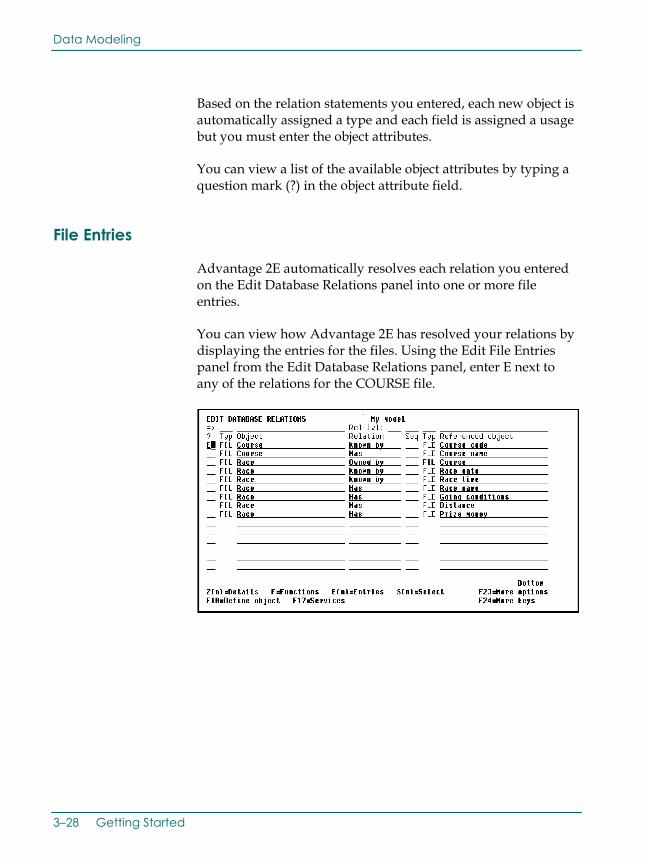
File Entries
Advantage 2E automatically resolves each relation you entered on the Edit Database Relations panel into one or more file entries.
You can view how Advantage 2E has resolved your relations by displaying the entries for the files. Using the Edit File Entries panel from the Edit Database Relations panel, enter E next to any of the relations for the COURSE file.
3–28 Getting Started

Data Modeling
A2GSG800.doc, printed on 9/3/2002, at 3:56 PM
Press Enter to display the Edit File Entries panel. This panel shows the file entries that were automatically created for the file as shown in the following illustration:
For each file entry, this panel displays the field names, the field type, whether the field is a key field (K) or an attribute (A), the Advantage 2E generated implementation name, and the field length. Note that Advantage 2E assigned the implementation name and default length based on the data type you specified; for example, for fields of type CDE, Advantage 2E assigns a 4-character implementation name ending in CD and a default length of 6.
Documenting Relations
To obtain a listing of the relations that you have entered, use the Document Model Relations (YDOCMDLREL) command. First press F17 from the Edit Database Relations panel to display the Display Services Menu. Then do one of the following:
■ Press F9 to display a command entry line, enter the YDOCMDLREL command, and press Enter.
■ Select the Documentation menu option to display a list of documentation commands and select Document model relations.
Usability Tour 3–29

Data Modeling
A2GSG800.doc, printed on 9/3/2002, at 3:56 PM
Field Details and Conditions
Having entered relations to define your data model, you must now add more detailed information about the fields. This includes defining simple validation rules and specifying any required overrides to the defaults Advantage 2E assigned for field properties such as field length.
Field conditions define both the values that a field may take and the meaning that the values represent.
For example, the Horse gender field of the HORSE file will be used to illustrate conditions. Enter Z2 against the HORSE Has Horse gender relation as shown.
3–30 Getting Started

Data Modeling
A2GSG800.doc, printed on 9/3/2002, at 3:56 PM
Edit Field Details
Press Enter to display the Edit Field Details panel for Horse gender.
To edit the Horse gender field, press F9 from the Edit Field Details panel to display the Edit Field Conditions panel. This panel shows the available conditions for the field. Initially, there are none.
Usability Tour 3–31

Data Modeling
A2GSG800.doc, printed on 9/3/2002, at 3:56 PM
Add Field Conditions
To add a field condition, enter the name and type of the condition. In this example, one value the Horse gender field can take is Stallion.
When you press Enter, the Edit Field Condition Details panel appears.
Add Field Condition Detail
The Edit Field Condition Details lets you specify the actual value that is to be stored in the database file to represent a particular condition. For example, you can distinguish between the definition of the condition (Stallion) and the value used to represent the condition on file (M).
3–32 Getting Started

Data Modeling
A2GSG800.doc, printed on 9/3/2002, at 3:56 PM
The condition value (or Status value) for Stallion is to be represented by an M in this example.
After pressing Enter, the panel is redisplayed, with the message “Condition ‘Stallion’ added” to indicate that the condition has been successfully added.
Relationship Extension
One file can be associated with another by means of the Refers to relation. A file can also reference another file more than once or to itself. In order to distinguish among multiple references to the same file, Advantage 2E provides an extended form of the Refers to relation that lets you specify differences among the relations using For text.
Usability Tour 3–33

Data Modeling
A2GSG800.doc, printed on 9/3/2002, at 3:56 PM
In our example, a horse’s parents are also horses. In order to record the horse’s parents, two HORSE Refers to HORSE relations—one for each parent—must be established, as shown in the following illustration:
Because the HORSE file refers to itself more than once, you will need to use the extended form of the Refers to relation in order to distinguish between the two relations.
For details on how this is done, see the Advantage 2E Tutorial.
Virtual Fields
A good database design stores each item of data in only one place, rather than having multiple copies in different files. The OS/400 join logical file is a mechanism for building views that assemble data from different files.
In Advantage 2E, you will use virtual fields to design such views. A virtual field is a field that is logically, but not physically, present in a file. Advantage 2E virtual fields are implemented through OS/400 join logical files.
When a file is referenced by another file by means of a Refers to relation, entries are automatically created on the referencing file for the key fields of the referenced file. These are known as foreign keys.
3–34 Getting Started

Data Modeling
A2GSG800.doc, printed on 9/3/2002, at 3:56 PM
To include a non-key field from the referenced file in the referencing file, you need to specify it as a virtual field. This makes the field available for use in the functions that operate upon the referencing file.
For example, to include the name of the horse when displaying the RACE ENTRY file, specify Horse name as a virtual field on the RACE ENTRY file. As a result, Horse name is physically present on the HORSE file, and is logically, but not physically, present on the RACE ENTRY file. This is shown in italics in the following figure.
Note that this same capability is available when two files are associated with each other by means of an Owned by relation. In other words, non-key fields from the owning file may be included in the owned file as virtual fields.
For further details, see the Advantage 2E Tutorial.
Usability Tour 3–35

Defining Access Paths
A2GSG800.doc, printed on 9/3/2002, at 3:56 PM
Defining Access Paths
DATA MODELING
ANALYSIS and
DESIGN
ACCESS PATHS
FUNCTIONS
PROGRAM COMPILATION
CODE GENERATION
The next stage in defining a design model is to define the required access paths. Access paths specify views of the files in the data model. The views define how data is to be presented to the functions. Functions specify the processes that operate on the data.
Access paths control three different aspects of how data is presented to a function. An access path determines:
■ Which fields will be available to the function
■ Which records will be selected or omitted from the file (select/omit)
■ The order in which records are presented (key sequence) to the function
Default Access Paths
Advantage 2E uses the relations in the data model to create a default set of access paths for each file. In many cases these will be sufficient. You may override the defaults or define additional access paths.
Three default access paths are automatically created for every file:
■ A physical (PHY) access path (un-keyed)—This contains the address of all data stored physically within a file and stored in the order in which the data was written to the file.
■ An update (UPD) access path (logical view)—This is used to update the file and contains all fields defined for the file. It cannot be altered.
■ A retrieval (RTV) access path (logical view)—This specifies a view of the data that Advantage 2E generated programs use to retrieve records from a file. Each file has at least one.
3–36 Getting Started

Defining Access Paths
A2GSG800.doc, printed on 9/3/2002, at 3:56 PM
View Default Access Paths
In our example, you can enter Course* on the selection line to display only relations for the COURSE file.
The access paths for a file are recorded on the Edit File Details panel. To obtain this panel for the COURSE file, you will zoom against one of the relations for the file on the Edit Database Relations panel. Enter Z against one of the relations for the COURSE file as shown in the following illustration:
Usability Tour 3–37

Defining Access Paths
A2GSG800.doc, printed on 9/3/2002, at 3:56 PM
Press Enter to display the Edit File Details panel.
This panel shows the three default access paths that Advantage 2E automatically created for the COURSE file.
From this point you can establish access paths with various rules, restrictions, and limitations to accomplish desirable results such as the following:
■ You can define an access path to select only certain relations from the file or to include selection criteria based on conditions specified for certain fields.
■ You can select or omit records from a view based on data values in specified fields. You can specify none, one, or many select/omit sets for a given access path.
■ You can define an access path as either static or dynamic. Static access paths are permanently built into the access paths of the OS/400 logical files so that the logical files only contain the records that meet the selection criteria. Dynamic access paths are not stored in the access path, but are applied to each record as it is retrieved.
For implementation details, see the Advantage 2E Tutorial.
3–38 Getting Started

Designing Functions
A2GSG800.doc, printed on 9/3/2002, at 3:56 PM
Designing Functions
DATA MODELING
ANALYSIS and
DESIGN
ACCESS PATHS
FUNCTIONS
PROGRAM COMPILATION
CODE GENERATION
A function defines a list of processes that will operate on the files and fields in your database. Advantage 2E provides a variety of standard functions based on your data model to which you can add your own unique processing.
A function can be implemented either as a separate program or as a subroutine within a program. An external function is implemented as a separate HLL program. Each external function is attached to an access path. In general, the standard device functions are external functions. An internal function is implemented as a subroutine of the program that calls it.
You can link functions together to create larger processes that become the building blocks of your applications.
In addition to the standard functions, Advantage 2E provides message functions, function fields, and built-in functions, that perform low-level processing such as arithmetic operations.
Default Reference File Functions
Advantage 2E automatically creates five default functions for each reference file (REF) you declare: two external functions (Edit File and Select Record), and three internal functions (Change Object, Create Object, and Delete Object).
The two external functions Advantage 2E automatically creates are:
■ Edit File (EDTFIL)—This type of function maintains multiple records on the file.
■ Select Record (SELRCD)—This type of function provides a display of the records on the file, and allows the selection of one record for return to a calling program.
Both of these external functions are interactive device functions.
Usability Tour 3–39

Designing Functions
A2GSG800.doc, printed on 9/3/2002, at 3:56 PM
The three internal functions Advantage 2E automatically creates are:
■ Change Object (CHGOBJ)
■ Create Object (CRTOBJ)
■ Delete Object (DLTOBJ).
These functions are used to update the database and are called by external functions as required. They are implemented as subroutines within the generated source code for an external function. Internal functions are specified separately to give you the capability to add additional processing for updating the database. This additional processing is made available to all the functions that call the internal functions.
The five default functions for a file are created the first time you enter F against the file on the Edit Database Relations panel. For example, to create the default functions for the COURSE file you would do the following.
First, display just those relations defined for the COURSE file by entering Course* on the selection line of the Edit Database Relations panel.
Next, display the functions for a particular file by typing F against the file on the Edit Database Relations panel. Enter F next to any COURSE file relation.
3–40 Getting Started

Designing Functions
A2GSG800.doc, printed on 9/3/2002, at 3:56 PM
If you press Enter, you can view the five default functions for the COURSE file. Advantage 2E displays messages at the bottom of the panel to indicate this.
New Functions
To add a new function you must first create it then define additional aspects of the function.
You might choose to add functions for the HORSE file, such as Select Mares and Select Stallions. These functions would enable you to display a list of mares only or stallions only in response to an inquiry.
You would begin by viewing a list of possible function types and access paths for the HORSE file by typing ? in the Function type column, and typing ? in the Access path column.
Usability Tour 3–41

Designing Functions
A2GSG800.doc, printed on 9/3/2002, at 3:56 PM
Enter the function names, function types, and access paths as shown in the following illustation:
Press Enter and the functions are added.
The two messages “Function ‘Select Mares’ is being created” and “Function ‘Select Stallions’ is being created” will appear briefly at the bottom of the panel. The functions will now be declared to your design model and are available for reference by other functions. At this stage no further definition is required but you will later need to define additional aspects of the new functions before they can be implemented.
Each interactive external function will be implemented by means of:
■ An HLL program
■ A DDS display file
■ A file containing Help text
The implementation language is controlled by the target HLL. You may generate in RPG, COBOL, UNIX, or Client Server Applications depending on your version of Advantage 2E.
The default implementation language for new functions is controlled by the YHLLGEN model value.
3–42 Getting Started

Designing Functions
A2GSG800.doc, printed on 9/3/2002, at 3:56 PM
Displaying Functions
To display the details of the Edit Horse function enter Z against the Edit Horse function.
Press Enter to view function details for the Edit Horse function. Note the program (RPG), display file (DDS), and the help text file (UIM).
Usability Tour 3–43

Designing Functions
A2GSG800.doc, printed on 9/3/2002, at 3:56 PM
Function Options
You can modify certain aspects of the behavior of a function as shown in the following example:
1. From the Edit Functions panel, enter Z against the Edit Horse function.
2. Press Enter to display the Edit Function Details panel.
3. Press F7 to view the Edit Function Options panel. The actual
function options available and their defaults depend on the function type.
3–44 Getting Started

Designing Functions
A2GSG800.doc, printed on 9/3/2002, at 3:56 PM
In this example the following options can be modified:
■ Delete record—This option specifies whether you can delete database records. The default is Y, which means you can delete database records. If you change this value to N, the function code will not include logic to delete database records.
■ Confirm prompt—The Confirm prompt option specifies whether the Edit Horse function prompts for confirmation before updating the database files. The default is Y.
If the Confirm prompt option is Y, a related option, Initially Yes, specifies whether the default for the confirm prompt will be Y or N.
Linking Functions
To link two functions together to build a larger function you must define the second function and an access path upon which it is based.
For example, you could modify the Edit Horse function so the user can zoom against the detail line for a particular horse on the Edit Horse panel in order to view a subsidiary display of the races in which the horse has raced.
Usability Tour 3–45

Designing Functions
A2GSG800.doc, printed on 9/3/2002, at 3:56 PM
To achieve this, you need to define a new function that you might name Display Racing results. Advantage 2E lets you define the new function while you are in the process of modifying the action diagram of the existing function.
Specifying Function Parameters
This section shows how to specify the parameters that will be passed to the Display Racing results function.
1. From the Edit Functions panel, enter P to edit the parameters.
2. Press Enter to display the Edit Function Parameters panel.
3–46 Getting Started

Designing Functions
A2GSG800.doc, printed on 9/3/2002, at 3:56 PM
3. Enter the details as shown. In other words, enter Race Entry as the file name, enter Races for a Horse as the access path, enter KEY as the Passed as value, and enter Z in the Subfile selector to select the key fields on the access path to be used as parameters.
4. Press Enter to display the Edit Function Parameter Details
panel.
The Horse code from the selected subfile record is to be passed as an input parameter to the Display Racing results function and will be restricted to show only race entries for this horse. This is where you specify that Horse code is an input only, restrictor parameter.
5. Enter R against Horse code.
Usability Tour 3–47

Designing Functions
A2GSG800.doc, printed on 9/3/2002, at 3:56 PM
6. Press Enter. The Usage for Horse code defaults to I (Input only) and the parameter role changs to RST (restrictor).
Default Panels
Advantage 2E automatically creates a default interactive panel design for each interactive device function. You can modify the default designs to meet the requirements of your application.
A device design specifies the following:
■ The selection of fields present on a device panel and the accompanying text for each field
The display of both fields and text may be conditional.
■ The order in which the fields are displayed on the device panel and how they are edited
■ The display attributes for the fields
■ The use of each field
These are the defaults from the design model but you may override most of them.
3–48 Getting Started

Designing Functions
A2GSG800.doc, printed on 9/3/2002, at 3:56 PM
You can view the default device design from the Edit Function Details panel by pressing F9.
The default panel design for the Edit Horse function displays.
If for example you want to change the position of a field on the device design all you need to do is position the cursor on the desired field then press the F9 function key. For example, to begin the second line with Dam Horse code, you simply place the cursor on this field and press F9. The subfile record format splits into two lines and the device design is updated to reflect the change.
Usability Tour 3–49

Designing Functions
A2GSG800.doc, printed on 9/3/2002, at 3:56 PM
Position cursor.
Press F9. The subfile record format now displays only two HORSE records.
If desired, you can repeat the process to move the fields relevant to the Sire to a separate line from those for the Dam by placing the cursor on the Sire Horse code and pressing F9.
For more details on modifying the device design, see the Advantage 2E Tutorial.
3–50 Getting Started

Designing Functions
A2GSG800.doc, printed on 9/3/2002, at 3:56 PM
Default Action Diagram
Advantage 2E supplies a default action diagram for each function. An action diagram contains the processing steps that make up a function. Each action diagram consists of a list of actions, where each action may be either a call to another function or one of a number of low level built-in functions.
To view and edit the default action diagram for the Edit Horse function, from the Edit Function panel enter F in the Subfile selector for the Edit Horse function.
Press Enter to view the action diagram for the Edit Horse function.
Usability Tour 3–51

Generating Source Code
A2GSG800.doc, printed on 9/3/2002, at 3:56 PM
The Action Diagram Editor’s Subfile selector provides options for editing an action diagram, including options for inserting and manipulating user-defined actions. You can enter ? in the Subfile selector to view a list of all allowed values.
Generating Source Code
DATA MODELING
ANALYSIS and
DESIGN
ACCESS PATHS
FUNCTIONS
PROGRAM COMPILATION
CODE GENERATION
You can generate source either interactively or in batch. Advantage 2E automatically keeps a list of the members to be generated and compiled that have not yet been compiled. We will take a look at how to use batch processing to generate source code and compile executable objects for all of your access paths and functions. These options are available on the Display Services Menu.
Generate Access Paths 1. From the Edit Database Relations panel, press F17 to go to
the Display Services Menu.
3–52 Getting Started

Generating Source Code
A2GSG800.doc, printed on 9/3/2002, at 3:56 PM
2. Select the Display all access paths option.
DISPLAY SERVICES MENU My model Generation 1. Submit model create request (YSBMMDLCRT) 2. convert model data menu 3. Job list menu Documentation 6. Documentation menu 7. Convert model panel designs (YCVTMDLPNL) Model 8. Display all access paths 9. Display all functions 10. Display model values (YDSPMDLVAL) 11. Edit model profile (YEDTMDLPRF) 12. Work with model lists (YWRKMDLLST) 13. Edit model list (YEDTMDLLST *SESSION) 14. Impact analysis menu Change Control 21. Go to 2ECM menu Option: 8 (press F4 to prompt commands) F3=Exit F6=Messages F8=Submitted jobs F9=Command line F10=Display job log
3. Press Enter.
Note: The Display All Access Paths panel also lets you perform many design, control, and generation tasks for one or more access paths.
4. Select all of the existing access path designs for batch generation and compilation by typing a J in the Subfile selector next to each access path in the list.
Usability Tour 3–53

Generating Source Code
A2GSG800.doc, printed on 9/3/2002, at 3:56 PM
5. Press Roll Up to display the next screen of access paths so you can select all remaining access paths with a J.
6. Press Enter.
7. When the process is complete, the Display All Access Paths panel will be redisplayed with messages displayed at the bottom of the panel. The messages will state that the source generation requests have been accepted.
8. Press F3 to return to the Display Services Menu.
3–54 Getting Started

Generating Source Code
A2GSG800.doc, printed on 9/3/2002, at 3:56 PM
Generate External Functions Source Code
Only external functions need to be generated and compiled. External functions can be identified by the source member name found in the GEN name column; internal functions show ∗N/A in this column.
List just the external functions in your design model by typing *EXT in the Type column on the selection line.
Proceed by selecting all functions and initiating the batch processing as you did for the access paths.
Usability Tour 3–55

Generating and Creating Compiled Objects
A2GSG800.doc, printed on 9/3/2002, at 3:56 PM
Generating and Creating Compiled Objects
DATA MODELING
ANALYSIS and
DESIGN
ACCESS PATHS
FUNCTIONS
PROGRAM COMPILATION
CODE GENERATION
When you submit a request for generation/compilation, the Advantage 2E generator automatically generates a job list. The same job list controls generation and compilation. You can review this job list during generation to monitor the process and edit the job list.
Source is produced and placed in the appropriate source file in the generation library associated with your Advantage 2E design model then the generated source is compiled. To begin, select the Submit model create request (YSBMMDLCRT) option and press Enter. The following screen is displayed:
DISPLAY SERVICES MENU My model Generation 1. Submit model create request (YSBMMDLCRT) 2. convert model data menu 3. Job list menu Documentation 6. Documentation menu 7. Convert model panel designs (YCVTMDLPNL) Model 8. Display all access paths 9. Display all functions 10. Display model values (YDSPMDLVAL) 11. Edit model profile (YEDTMDLPRF) 12. Work with model lists (YWRKMDLLST) 13. Edit model list (YEDTMDLLST *SESSION) 14. Impact analysis menu Change Control 21. Go to 2ECM menu Option: 1 (press F4 to prompt commands) F3=Exit F6=Messages F8=Submitted jobs F9=Command line F10=Display job log
Note: Advantage 2E supplies default parameter values for the YSBMMDLCRT command based on your model profile and options you specified when you created your model. You can override these defaults by pressing F4 instead of Enter to prompt the command.
3–56 Getting Started

Generating and Creating Compiled Objects
A2GSG800.doc, printed on 9/3/2002, at 3:56 PM
Advantage 2E displays a list of the source members to be generated and compiled. Each member has either GEN or CRT next to it to indicate whether the member has been submitted for generation or compilation. At this point, all the functions and access paths should show GEN.
Press Roll Up until you see the bottom of the list, then Press Enter to submit the job list.
After confirming the list of objects, you will see the following series of messages at the bottom of the panel:
■ Job YGENSRC is being prepared
■ Existing objects are being deleted
■ Joblist successfully processed
In batch processing, the generations/compilations take place in the background. You may continue to specify new objects (functions, access paths) while the batch is processing.
Before calling your program, you must use the Convert Condition Values (YCVTCNDVAL) command to convert the values that are entered into status fields. The values you defined for status fields are moved from the model library to the condition values list database file in the generation library.
Usability Tour 3–57

Generating and Creating Compiled Objects
A2GSG800.doc, printed on 9/3/2002, at 3:56 PM
Horse gender is an example of a status field. We specified the valid values for this field in our model library and those values are placed in the generation library database when we run the Convert Condition Values (YCVTCNDVAL) command. In this case, the end user running the application will then be able to select either M or F as valid values for Horse gender.
When you exit this session, if you have added or changed any files, fields, or relations in the current session, you might want to resynchronize.
The resynchronize process causes all the relations to be resolved into entries. Only users of enter *DSNR can resynchronize a model.
Select the desired option, then press Enter.
Testing Your Programs
You can call your compiled programs from any command entry line by using the OS/400 CALL command to invoke your program, as shown with MYAEEFR in the following example. From within your model, you can display a command entry line by pressing F9 from the Display Services menu.
3–58 Getting Started

A2GSG800.doc, printed on 9/3/2002, at 3:56 PM
Note: If you do not know the name of your program, you can obtain it from the Edit Function Details panel or the Display all functions option on the Display Services Menu.
When you call your program you need to specify a dummy *Return code parameter. All Advantage 2E programs require a dummy parameter to be passed to the program. This return code can be used to communicate between programs in more complex applications.
Enter the program name and return code, then press Enter
MAIN 2E Main Menu Level . : 1 System: 2EDV1 Select one of the following: Design Model 1. Display Designer (*DSNR) menu 2. Display Programmer (*PGMR) menu 3. Display User (*USER) menu 8. Work with Model Object Lists 9. Change to work with another model Commands 50. 2E commands in alphabetical order 51. Commands to set up or alter a model 52. Commands to copy a model 53. Commands to create an application 54. Commands to document a model More. . . Selection or command ===> call myaeefr **_________________________________________ ______________________________________________________________ F3=Exit F6=Messages F9=Prev. request F10=Cmd Entry F14=Submitted jobs Maximum capability to access model MYMDL is *DSLK.
Note: To test complex programs, you can use the Advantage 2E Call a Program (Y2CALL) command. This command loads your model and determines the parameters required by an external function directly from details contained in the model. You can provide values for all input-capable fields and you can re-use these values for subsequent calls. You can also retrieve and display output parameters when the called program ends.
Usability Tour 3–59
Related Documents