Grace for Code Composer Studio™ IDE Getting Started Guide Literature Number: SLAU476A December 2012– Revised June 2014

Welcome message from author
This document is posted to help you gain knowledge. Please leave a comment to let me know what you think about it! Share it to your friends and learn new things together.
Transcript
Grace for Code Composer Studio™ IDE
Getting Started Guide
Literature Number: SLAU476ADecember 2012–Revised June 2014

Contents
1 Introduction......................................................................................................................... 41.1 Supported Devices....................................................................................................... 41.2 Purpose of Grace ........................................................................................................ 41.3 Grace, MSP430Ware, and Driver Library ............................................................................. 4
2 Installing Grace.................................................................................................................... 53 Starting a Grace Project........................................................................................................ 64 Configuring G2xx and F2xx Devices ..................................................................................... 10
4.1 Overview Page for G2xx and F2xx Devices ........................................................................ 104.2 Basic and Power User Views for G2xx and F2xx Devices ........................................................ 114.3 GPIO Configuration for G2xx and F2xx Devices ................................................................... 12
5 Configuring FR5xx Devices ................................................................................................. 145.1 Pin Mux (GPIO) Configuration for FR5xx Devices ................................................................. 15
6 Building the Project ............................................................................................................ 167 Using Grace Snippets ......................................................................................................... 178 Reviewing the Generated Source Code ................................................................................. 189 Interrupt Handling .............................................................................................................. 1910 Revision History................................................................................................................. 21
2 Table of Contents SLAU476A–December 2012–Revised June 2014Submit Documentation Feedback
Copyright © 2012–2014, Texas Instruments Incorporated
www.ti.com
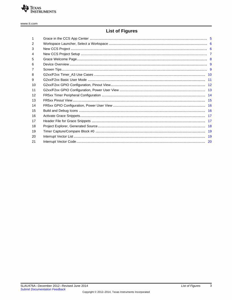
List of Figures1 Grace in the CCS App Center ............................................................................................. 52 Workspace Launcher, Select a Workspace .............................................................................. 63 New CCS Project ............................................................................................................ 64 New CCS Project Setup .................................................................................................... 75 Grace Welcome Page....................................................................................................... 86 Device Overview ............................................................................................................. 97 Screen Tips ................................................................................................................... 98 G2xx/F2xx Timer_A3 Use Cases ........................................................................................ 109 G2xx/F2xx Basic User Mode ............................................................................................. 1110 G2xx/F2xx GPIO Configuration, Pinout View........................................................................... 1211 G2xx/F2xx GPIO Configuration, Power User View .................................................................... 1312 FR5xx Timer Peripheral Configuration .................................................................................. 1413 FR5xx Pinout View ......................................................................................................... 1514 FR5xx GPIO Configuration, Power User View ......................................................................... 1615 Build and Debug Icons .................................................................................................... 1616 Activate Grace Snippets................................................................................................... 1717 Header File for Grace Snippets .......................................................................................... 1718 Project Explorer, Generated Source ..................................................................................... 1819 Timer Capture/Compare Block #0 ....................................................................................... 1920 Interrupt Vector List ........................................................................................................ 1921 Interrupt Vector Code ...................................................................................................... 20
3SLAU476A–December 2012–Revised June 2014 List of FiguresSubmit Documentation Feedback
Copyright © 2012–2014, Texas Instruments Incorporated
Getting Started GuideSLAU476A–December 2012–Revised June 2014
Grace for Code Composer Studio™ IDE
1 IntroductionGrace provides an intuitive way to configure MSP430™ microcontroller devices. The Grace tool is a plug-in to Code Composer Studio (CCS) that allows MSP430 developers to generate peripheral setup codewithin minutes. Typical application use cases are provided with easy-to-follow steps for initial peripheralconfiguration. In addition, ready-to-use code snippets for peripheral runtime control can be copied straightinto your applications.
1.1 Supported DevicesFor a list of supported devices, see the Grace Quick Start Guide.
1.2 Purpose of GraceCode generated by Grace covers only device initialization. After device initialization, the first function thatis usually executed is the main function, and there is no further interaction between Grace and theapplication code.
1.3 Grace, MSP430Ware, and Driver LibraryFor MSP430FR5xx devices, a low-level library (Driver Library) is available. Grace uses the Driver Libraryto configure the MCU. It does this by generating source code for the FRAM devices. The source codemakes calls to the MSP430 Driver Library. You can use the Driver Library in your application code. Directregister access is also possible.
The Driver Library for MSP430FR5xx devices is available as either a standalone component or as part ofMSP430Ware. The easiest way to make sure that the Driver Library is installed is to use the App Center inCode Composer Studio 6 to install Grace.
The Driver Library API documentation can be found in the TI Resource Explorer. Select TI ResourceExplorer from the View menu. Then select MSP430Ware → Libraries → DriverLib → User's Guide forthe documentation.
MSP430F2xx and MSP430G2xx devices are not supported through the Driver Library. Instead, Graceprovides support by directly accessing the peripheral registers.
Code Composer Studio, MSP430 are trademarks of Texas Instruments.4 Grace for Code Composer Studio™ IDE SLAU476A–December 2012–Revised June 2014
Submit Documentation FeedbackCopyright © 2012–2014, Texas Instruments Incorporated
www.ti.com Installing Grace
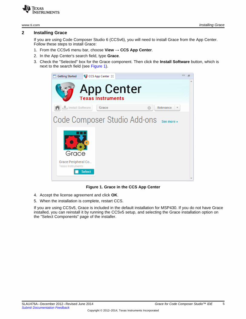
2 Installing GraceIf you are using Code Composer Studio 6 (CCSv6), you will need to install Grace from the App Center.Follow these steps to install Grace:1. From the CCSv6 menu bar, choose View → CCS App Center.2. In the App Center's search field, type Grace.3. Check the "Selected" box for the Grace component. Then click the Install Software button, which is
next to the search field (see Figure 1).
Figure 1. Grace in the CCS App Center
4. Accept the license agreement and click OK.5. When the installation is complete, restart CCS.
If you are using CCSv5, Grace is included in the default installation for MSP430. If you do not have Graceinstalled, you can reinstall it by running the CCSv5 setup, and selecting the Grace installation option onthe "Select Components" page of the installer.
5SLAU476A–December 2012–Revised June 2014 Grace for Code Composer Studio™ IDESubmit Documentation Feedback
Copyright © 2012–2014, Texas Instruments Incorporated
Starting a Grace Project www.ti.com
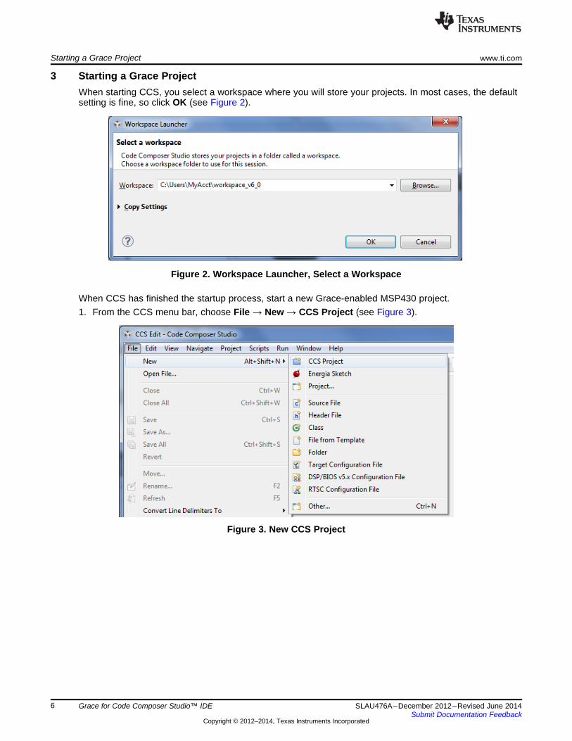
3 Starting a Grace ProjectWhen starting CCS, you select a workspace where you will store your projects. In most cases, the defaultsetting is fine, so click OK (see Figure 2).
Figure 2. Workspace Launcher, Select a Workspace
When CCS has finished the startup process, start a new Grace-enabled MSP430 project.1. From the CCS menu bar, choose File → New → CCS Project (see Figure 3).
Figure 3. New CCS Project
6 Grace for Code Composer Studio™ IDE SLAU476A–December 2012–Revised June 2014Submit Documentation Feedback
Copyright © 2012–2014, Texas Instruments Incorporated
www.ti.com Starting a Grace Project
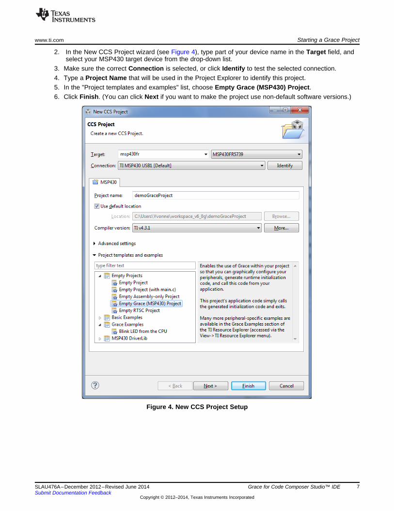
2. In the New CCS Project wizard (see Figure 4), type part of your device name in the Target field, andselect your MSP430 target device from the drop-down list.
3. Make sure the correct Connection is selected, or click Identify to test the selected connection.4. Type a Project Name that will be used in the Project Explorer to identify this project.5. In the "Project templates and examples" list, choose Empty Grace (MSP430) Project.6. Click Finish. (You can click Next if you want to make the project use non-default software versions.)
Figure 4. New CCS Project Setup
7SLAU476A–December 2012–Revised June 2014 Grace for Code Composer Studio™ IDESubmit Documentation Feedback
Copyright © 2012–2014, Texas Instruments Incorporated
Starting a Grace Project www.ti.com
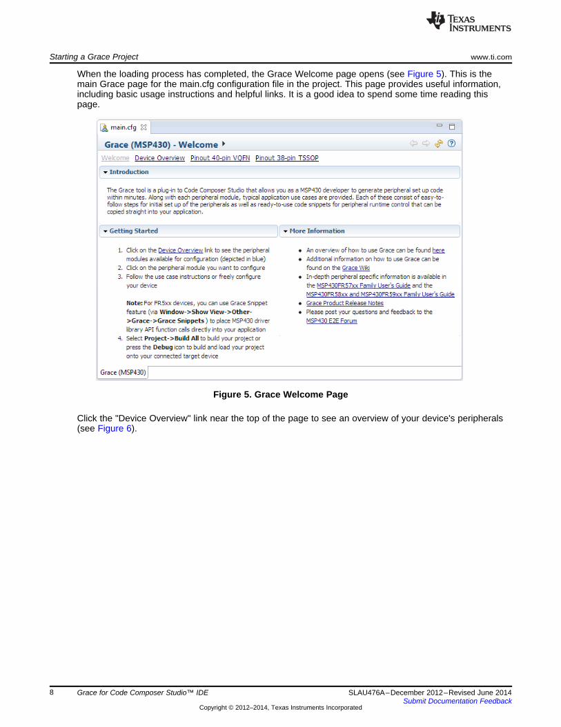
When the loading process has completed, the Grace Welcome page opens (see Figure 5). This is themain Grace page for the main.cfg configuration file in the project. This page provides useful information,including basic usage instructions and helpful links. It is a good idea to spend some time reading thispage.
Figure 5. Grace Welcome Page
Click the "Device Overview" link near the top of the page to see an overview of your device's peripherals(see Figure 6).
8 Grace for Code Composer Studio™ IDE SLAU476A–December 2012–Revised June 2014Submit Documentation Feedback
Copyright © 2012–2014, Texas Instruments Incorporated
www.ti.com Starting a Grace Project
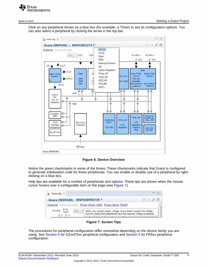
Click on any peripheral shown as a blue box (for example, a Timer) to see its configuration options. Youcan also select a peripheral by clicking the arrow in the top bar.
Figure 6. Device Overview
Notice the green checkmarks in some of the boxes. These checkmarks indicate that Grace is configuredto generate initialization code for these peripherals. You can enable or disable use of a peripheral by right-clicking on a blue box.
Help tips are available for a number of peripherals and options. These tips are shown when the mousecursor hovers over a configurable item on the page (see Figure 7).
Figure 7. Screen Tips
The procedures for peripheral configuration differ somewhat depending on the device family you areusing. See Section 4 for G2xx/F2xx peripheral configuration and Section 5 for FR5xx peripheralconfiguration.
9SLAU476A–December 2012–Revised June 2014 Grace for Code Composer Studio™ IDESubmit Documentation Feedback
Copyright © 2012–2014, Texas Instruments Incorporated
Configuring G2xx and F2xx Devices www.ti.com
4 Configuring G2xx and F2xx DevicesFor G2xx/F2xx devices, in the Device Overview diagram, click on any peripheral shown as a blue box (forexample, a Timer) to see its configuration options. You can also select a peripheral by clicking the arrowin the top bar. Notice the green checkmarks in some of the boxes. These checkmarks indicate that Graceis configured to generate initialization code for these peripherals.
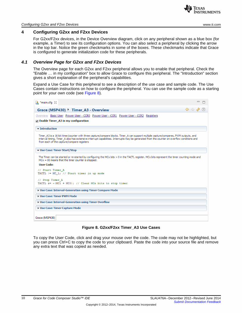
4.1 Overview Page for G2xx and F2xx DevicesThe Overview page for each G2xx and F2xx peripheral allows you to enable that peripheral. Check the"Enable … in my configuration" box to allow Grace to configure this peripheral. The "Introduction" sectiongives a short explanation of the peripheral's capabilities.
Expand a Use Case for this peripheral to see a description of the use case and sample code. The UseCases contain instructions on how to configure the peripheral. You can use the sample code as a startingpoint for your own code (see Figure 8).
Figure 8. G2xx/F2xx Timer_A3 Use Cases
To copy the User Code, click and drag your mouse over the code. The code may not be highlighted, butyou can press Ctrl+C to copy the code to your clipboard. Paste the code into your source file and removeany extra text that was copied as needed.
10 Grace for Code Composer Studio™ IDE SLAU476A–December 2012–Revised June 2014Submit Documentation Feedback
Copyright © 2012–2014, Texas Instruments Incorporated
www.ti.com Configuring G2xx and F2xx Devices
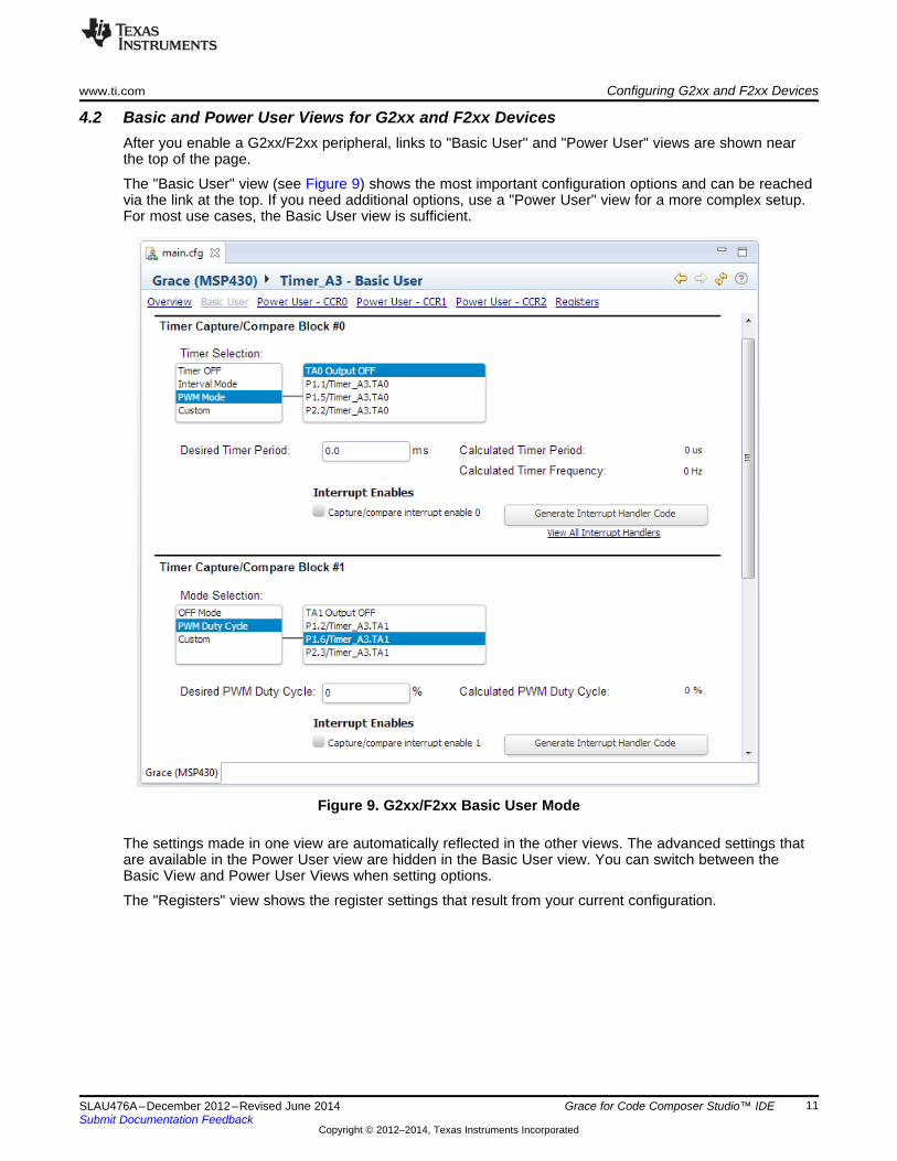
4.2 Basic and Power User Views for G2xx and F2xx DevicesAfter you enable a G2xx/F2xx peripheral, links to "Basic User" and "Power User" views are shown nearthe top of the page.
The "Basic User" view (see Figure 9) shows the most important configuration options and can be reachedvia the link at the top. If you need additional options, use a "Power User" view for a more complex setup.For most use cases, the Basic User view is sufficient.
Figure 9. G2xx/F2xx Basic User Mode
The settings made in one view are automatically reflected in the other views. The advanced settings thatare available in the Power User view are hidden in the Basic User view. You can switch between theBasic View and Power User Views when setting options.
The "Registers" view shows the register settings that result from your current configuration.
11SLAU476A–December 2012–Revised June 2014 Grace for Code Composer Studio™ IDESubmit Documentation Feedback
Copyright © 2012–2014, Texas Instruments Incorporated
Configuring G2xx and F2xx Devices www.ti.com
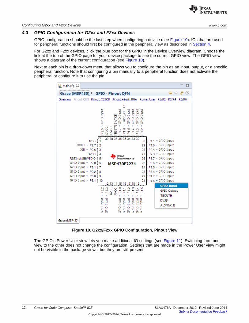
4.3 GPIO Configuration for G2xx and F2xx DevicesGPIO configuration should be the last step when configuring a device (see Figure 10). IOs that are usedfor peripheral functions should first be configured in the peripheral view as described in Section 4.
For G2xx and F2xx devices, click the blue box for the GPIO in the Device Overview diagram. Choose thelink at the top of the GPIO page for your device package to see the correct GPIO view. The GPIO viewshows a diagram of the current configuration (see Figure 10).
Next to each pin is a drop-down menu that allows you to configure the pin as an input, output, or a specificperipheral function. Note that configuring a pin manually to a peripheral function does not activate theperipheral or configure it to use the pin.
Figure 10. G2xx/F2xx GPIO Configuration, Pinout View
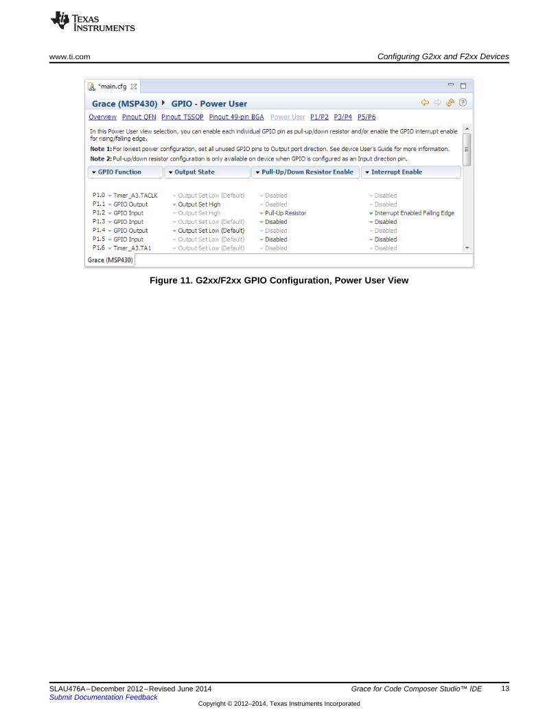
The GPIO's Power User view lets you make additional IO settings (see Figure 11). Switching from oneview to the other does not change the configuration. Settings that are made in the Power User view mightnot be visible in the package views, but they are still present.
12 Grace for Code Composer Studio™ IDE SLAU476A–December 2012–Revised June 2014Submit Documentation Feedback
Copyright © 2012–2014, Texas Instruments Incorporated
www.ti.com Configuring G2xx and F2xx Devices
Figure 11. G2xx/F2xx GPIO Configuration, Power User View
13SLAU476A–December 2012–Revised June 2014 Grace for Code Composer Studio™ IDESubmit Documentation Feedback
Copyright © 2012–2014, Texas Instruments Incorporated
Configuring FR5xx Devices www.ti.com
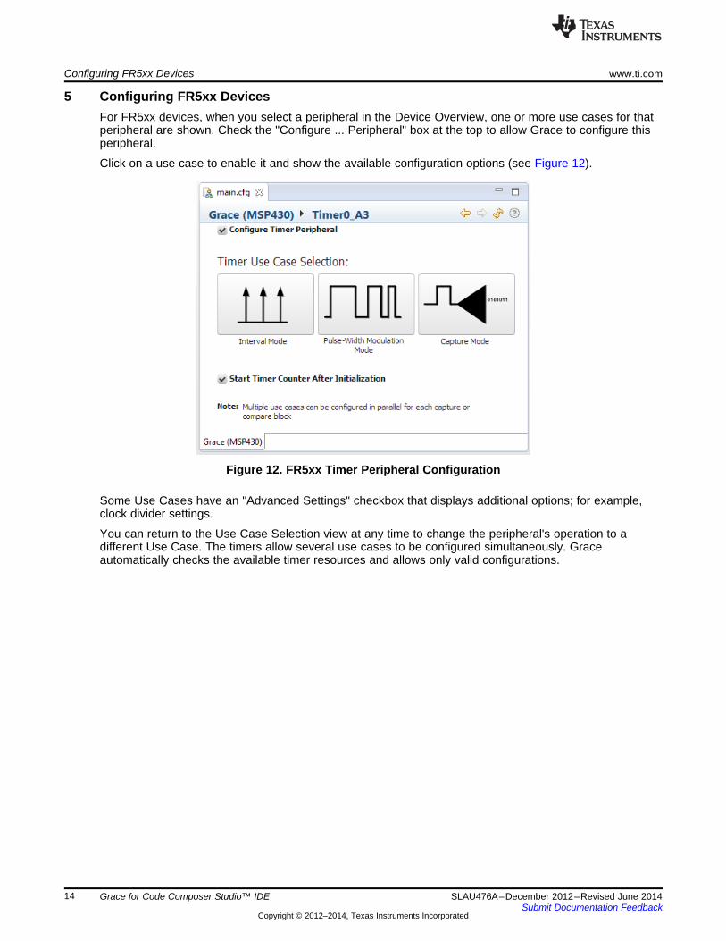
5 Configuring FR5xx DevicesFor FR5xx devices, when you select a peripheral in the Device Overview, one or more use cases for thatperipheral are shown. Check the "Configure ... Peripheral" box at the top to allow Grace to configure thisperipheral.
Click on a use case to enable it and show the available configuration options (see Figure 12).
Figure 12. FR5xx Timer Peripheral Configuration
Some Use Cases have an "Advanced Settings" checkbox that displays additional options; for example,clock divider settings.
You can return to the Use Case Selection view at any time to change the peripheral's operation to adifferent Use Case. The timers allow several use cases to be configured simultaneously. Graceautomatically checks the available timer resources and allows only valid configurations.
14 Grace for Code Composer Studio™ IDE SLAU476A–December 2012–Revised June 2014Submit Documentation Feedback
Copyright © 2012–2014, Texas Instruments Incorporated
www.ti.com Configuring FR5xx Devices
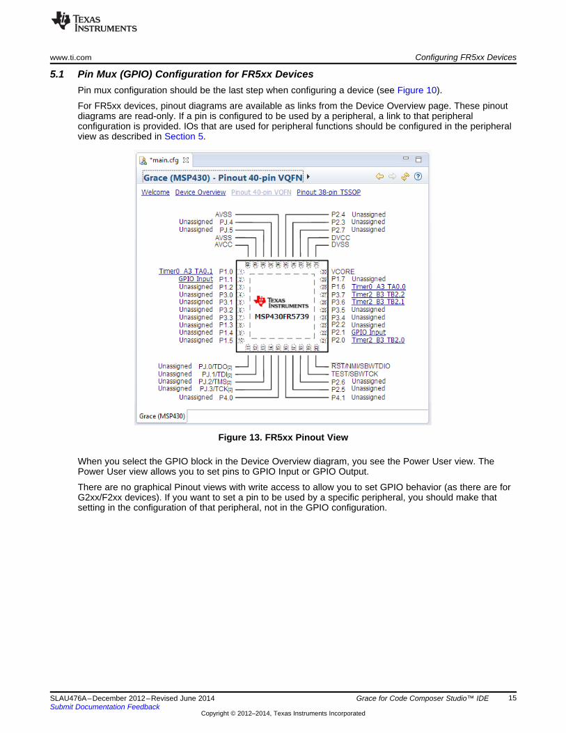
5.1 Pin Mux (GPIO) Configuration for FR5xx DevicesPin mux configuration should be the last step when configuring a device (see Figure 10).
For FR5xx devices, pinout diagrams are available as links from the Device Overview page. These pinoutdiagrams are read-only. If a pin is configured to be used by a peripheral, a link to that peripheralconfiguration is provided. IOs that are used for peripheral functions should be configured in the peripheralview as described in Section 5.
Figure 13. FR5xx Pinout View
When you select the GPIO block in the Device Overview diagram, you see the Power User view. ThePower User view allows you to set pins to GPIO Input or GPIO Output.
There are no graphical Pinout views with write access to allow you to set GPIO behavior (as there are forG2xx/F2xx devices). If you want to set a pin to be used by a specific peripheral, you should make thatsetting in the configuration of that peripheral, not in the GPIO configuration.
15SLAU476A–December 2012–Revised June 2014 Grace for Code Composer Studio™ IDESubmit Documentation Feedback
Copyright © 2012–2014, Texas Instruments Incorporated
Building the Project www.ti.com
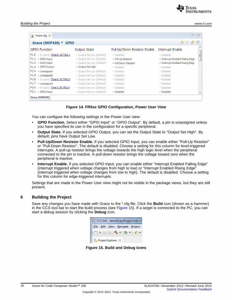
Figure 14. FR5xx GPIO Configuration, Power User View
You can configure the following settings in the Power User view:• GPIO Function. Select either "GPIO Input" or "GPIO Output". By default, a pin is unassigned unless
you have specified its use in the configuration for a specific peripheral.• Output State. If you selected GPIO Output, you can set the Output State to "Output Set High". By
default, pins have Output Set Low.• Pull-Up/Down Resistor Enable. If you selected GPIO Input, you can enable either "Pull-Up Resistor"
or "Pull-Down Resistor". The default is disabled. Choose a setting for this column for level-triggeredinterrupts. A pull-up resistor brings the voltage towards the high logic level when the peripheralconnected to the pin is inactive. A pull-down resistor brings the voltage toward zero when theperipheral is inactive.
• Interrupt Enable. If you selected GPIO Input, you can enable either "Interrupt Enabled Falling Edge"(interrupt triggered when voltage changes from high to low) or "Interrupt Enabled Rising Edge"(interrupt triggered when voltage changes from low to high). The default is disabled. Choose a settingfor this column for edge-triggered interrupts.
Settings that are made in the Power User view might not be visible in the package views, but they are stillpresent.
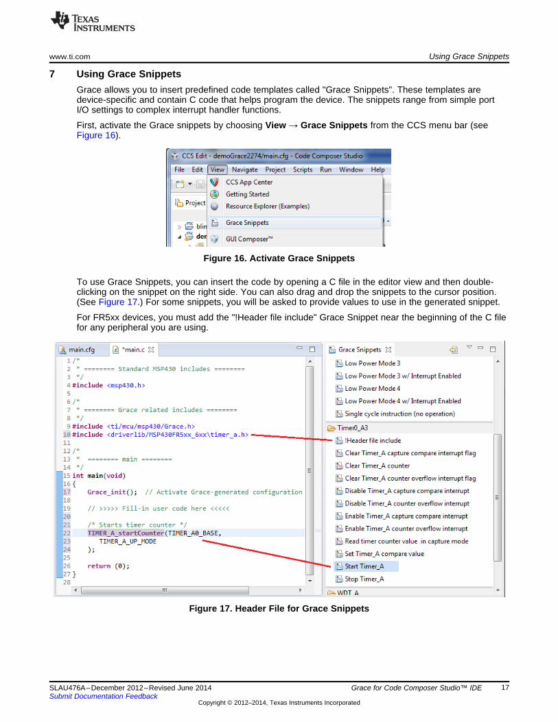
6 Building the ProjectSave any changes you have made with Grace to the *.cfg file. Click the Build icon (shown as a hammer)in the CCS tool bar to start the build process (see Figure 15). If a target is connected to the PC, you canstart a debug session by clicking the Debug icon.
Figure 15. Build and Debug Icons
16 Grace for Code Composer Studio™ IDE SLAU476A–December 2012–Revised June 2014Submit Documentation Feedback
Copyright © 2012–2014, Texas Instruments Incorporated
www.ti.com Using Grace Snippets
7 Using Grace SnippetsGrace allows you to insert predefined code templates called "Grace Snippets". These templates aredevice-specific and contain C code that helps program the device. The snippets range from simple portI/O settings to complex interrupt handler functions.
First, activate the Grace snippets by choosing View → Grace Snippets from the CCS menu bar (seeFigure 16).
Figure 16. Activate Grace Snippets
To use Grace Snippets, you can insert the code by opening a C file in the editor view and then double-clicking on the snippet on the right side. You can also drag and drop the snippets to the cursor position.(See Figure 17.) For some snippets, you will be asked to provide values to use in the generated snippet.
For FR5xx devices, you must add the "!Header file include" Grace Snippet near the beginning of the C filefor any peripheral you are using.
Figure 17. Header File for Grace Snippets
17SLAU476A–December 2012–Revised June 2014 Grace for Code Composer Studio™ IDESubmit Documentation Feedback
Copyright © 2012–2014, Texas Instruments Incorporated
Reviewing the Generated Source Code www.ti.com
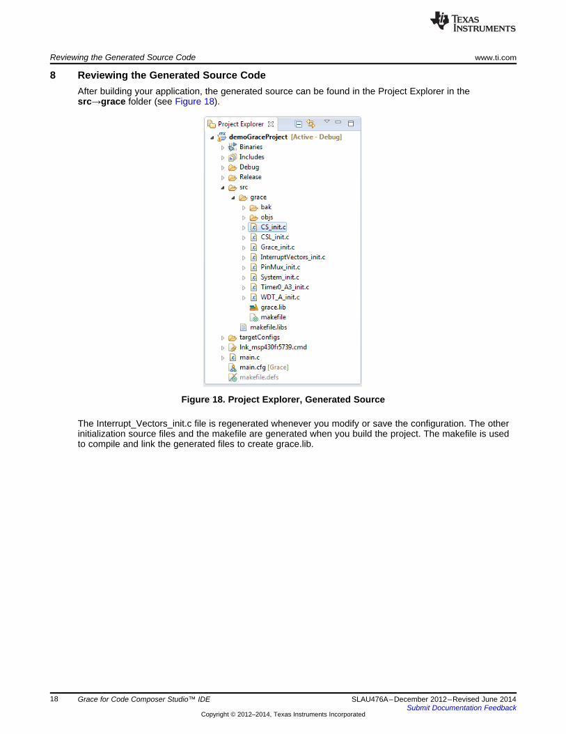
8 Reviewing the Generated Source CodeAfter building your application, the generated source can be found in the Project Explorer in thesrc→grace folder (see Figure 18).
Figure 18. Project Explorer, Generated Source
The Interrupt_Vectors_init.c file is regenerated whenever you modify or save the configuration. The otherinitialization source files and the makefile are generated when you build the project. The makefile is usedto compile and link the generated files to create grace.lib.
18 Grace for Code Composer Studio™ IDE SLAU476A–December 2012–Revised June 2014Submit Documentation Feedback
Copyright © 2012–2014, Texas Instruments Incorporated
www.ti.com Interrupt Handling
9 Interrupt HandlingGrace lets you manage peripheral interrupts efficiently.
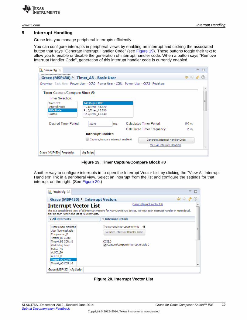
You can configure interrupts in peripheral views by enabling an interrupt and clicking the associatedbutton that says "Generate Interrupt Handler Code" (see Figure 19). These buttons toggle their text toallow you to enable or disable the generation of interrupt handler code. When a button says "RemoveInterrupt Handler Code", generation of this interrupt handler code is currently enabled.
Figure 19. Timer Capture/Compare Block #0
Another way to configure interrupts in to open the Interrupt Vector List by clicking the "View All InterruptHandlers" link in a peripheral view. Select an interrupt from the list and configure the settings for thatinterrupt on the right. (See Figure 20.)
Figure 20. Interrupt Vector List
19SLAU476A–December 2012–Revised June 2014 Grace for Code Composer Studio™ IDESubmit Documentation Feedback
Copyright © 2012–2014, Texas Instruments Incorporated
Interrupt Handling www.ti.com
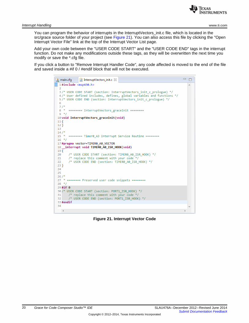
You can program the behavior of interrupts in the InterruptVectors_init.c file, which is located in thesrc/grace source folder of your project (see Figure 21). You can also access this file by clicking the "OpenInterrupt Vector File" link at the top of the Interrupt Vector List page.
Add your own code between the "USER CODE START" and the "USER CODE END" tags in the interruptfunction. Do not make any modifications outside these tags, as they will be overwritten the next time youmodify or save the *.cfg file.
If you click a button to "Remove Interrupt Handler Code", any code affected is moved to the end of the fileand saved inside a #if 0 / #endif block that will not be executed.
Figure 21. Interrupt Vector Code
20 Grace for Code Composer Studio™ IDE SLAU476A–December 2012–Revised June 2014Submit Documentation Feedback
Copyright © 2012–2014, Texas Instruments Incorporated
www.ti.com Revision History
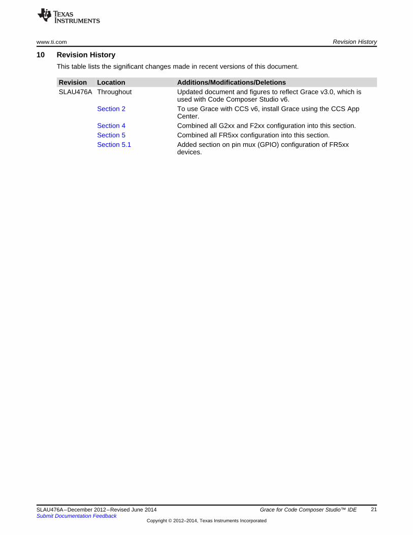
10 Revision HistoryThis table lists the significant changes made in recent versions of this document.
Revision Location Additions/Modifications/DeletionsSLAU476A Throughout Updated document and figures to reflect Grace v3.0, which is
used with Code Composer Studio v6.Section 2 To use Grace with CCS v6, install Grace using the CCS App
Center.Section 4 Combined all G2xx and F2xx configuration into this section.Section 5 Combined all FR5xx configuration into this section.Section 5.1 Added section on pin mux (GPIO) configuration of FR5xx
devices.
21SLAU476A–December 2012–Revised June 2014 Grace for Code Composer Studio™ IDESubmit Documentation Feedback
Copyright © 2012–2014, Texas Instruments Incorporated

IMPORTANT NOTICE
Texas Instruments Incorporated and its subsidiaries (TI) reserve the right to make corrections, enhancements, improvements and otherchanges to its semiconductor products and services per JESD46, latest issue, and to discontinue any product or service per JESD48, latestissue. Buyers should obtain the latest relevant information before placing orders and should verify that such information is current andcomplete. All semiconductor products (also referred to herein as “components”) are sold subject to TI’s terms and conditions of salesupplied at the time of order acknowledgment.TI warrants performance of its components to the specifications applicable at the time of sale, in accordance with the warranty in TI’s termsand conditions of sale of semiconductor products. Testing and other quality control techniques are used to the extent TI deems necessaryto support this warranty. Except where mandated by applicable law, testing of all parameters of each component is not necessarilyperformed.TI assumes no liability for applications assistance or the design of Buyers’ products. Buyers are responsible for their products andapplications using TI components. To minimize the risks associated with Buyers’ products and applications, Buyers should provideadequate design and operating safeguards.TI does not warrant or represent that any license, either express or implied, is granted under any patent right, copyright, mask work right, orother intellectual property right relating to any combination, machine, or process in which TI components or services are used. Informationpublished by TI regarding third-party products or services does not constitute a license to use such products or services or a warranty orendorsement thereof. Use of such information may require a license from a third party under the patents or other intellectual property of thethird party, or a license from TI under the patents or other intellectual property of TI.Reproduction of significant portions of TI information in TI data books or data sheets is permissible only if reproduction is without alterationand is accompanied by all associated warranties, conditions, limitations, and notices. TI is not responsible or liable for such altereddocumentation. Information of third parties may be subject to additional restrictions.Resale of TI components or services with statements different from or beyond the parameters stated by TI for that component or servicevoids all express and any implied warranties for the associated TI component or service and is an unfair and deceptive business practice.TI is not responsible or liable for any such statements.Buyer acknowledges and agrees that it is solely responsible for compliance with all legal, regulatory and safety-related requirementsconcerning its products, and any use of TI components in its applications, notwithstanding any applications-related information or supportthat may be provided by TI. Buyer represents and agrees that it has all the necessary expertise to create and implement safeguards whichanticipate dangerous consequences of failures, monitor failures and their consequences, lessen the likelihood of failures that might causeharm and take appropriate remedial actions. Buyer will fully indemnify TI and its representatives against any damages arising out of the useof any TI components in safety-critical applications.In some cases, TI components may be promoted specifically to facilitate safety-related applications. With such components, TI’s goal is tohelp enable customers to design and create their own end-product solutions that meet applicable functional safety standards andrequirements. Nonetheless, such components are subject to these terms.No TI components are authorized for use in FDA Class III (or similar life-critical medical equipment) unless authorized officers of the partieshave executed a special agreement specifically governing such use.Only those TI components which TI has specifically designated as military grade or “enhanced plastic” are designed and intended for use inmilitary/aerospace applications or environments. Buyer acknowledges and agrees that any military or aerospace use of TI componentswhich have not been so designated is solely at the Buyer's risk, and that Buyer is solely responsible for compliance with all legal andregulatory requirements in connection with such use.TI has specifically designated certain components as meeting ISO/TS16949 requirements, mainly for automotive use. In any case of use ofnon-designated products, TI will not be responsible for any failure to meet ISO/TS16949.
Products ApplicationsAudio www.ti.com/audio Automotive and Transportation www.ti.com/automotiveAmplifiers amplifier.ti.com Communications and Telecom www.ti.com/communicationsData Converters dataconverter.ti.com Computers and Peripherals www.ti.com/computersDLP® Products www.dlp.com Consumer Electronics www.ti.com/consumer-appsDSP dsp.ti.com Energy and Lighting www.ti.com/energyClocks and Timers www.ti.com/clocks Industrial www.ti.com/industrialInterface interface.ti.com Medical www.ti.com/medicalLogic logic.ti.com Security www.ti.com/securityPower Mgmt power.ti.com Space, Avionics and Defense www.ti.com/space-avionics-defenseMicrocontrollers microcontroller.ti.com Video and Imaging www.ti.com/videoRFID www.ti-rfid.comOMAP Applications Processors www.ti.com/omap TI E2E Community e2e.ti.comWireless Connectivity www.ti.com/wirelessconnectivity
Mailing Address: Texas Instruments, Post Office Box 655303, Dallas, Texas 75265Copyright © 2014, Texas Instruments Incorporated
Related Documents