Gesture Control Robot With Adaptive Gripper Muttepwar Venkatesh V Gaurav Naleshwarkar Arockia Selvakumar A * SMBS, VIT University, Chennai, India * [email protected] Abstract The primary aim of implementing the robots is to decrease the human efforts. The field may either be industrial or domestic. It is user who decides the use of robot according to the applications involved in the process. The industrial robots are constrained for required operation. This research concentrates on the domestic e of the robot as a helping hand application. The research has been concentrated on the design and development of the end- effector with adaptive abilities to hold the various objects in day to day life. The gripper parameters have been obtained using the FESTO’s manual for calculation of gripping force. The design of the griper has undergone improvisations for two times. The flex sensors have been used as the filtering out the low frequency signals in accelerometers is tedious. The four bar mechanism has been simulated and simulation results have been obtained. Considering the complexity in manufacturing of four bar mechanism, the LO configuration has been used on actual model. The wireless communication has been implemented to establish the connection between transmission and receiver end. The data transmission efficiency has been checked to ensure that the wireless modules work properly. The simulation results of four bar mechanism along with the gripping force calculations have discussed. The development of algorithm for control system of robot is prepared but yet to be tested for various test cases. The objective of this research is to provide the helping hand for physically disabled/physically challenged people. Keywords: Flex sensors, four bar mechanism, LO cofinguration, adaptive gripper, gripping force. 1 Introduction Robot, now a days, is a device that can perform a single or multiple tasks at a time. The robot has got ability of performing work, defined for a particular area of interest. Generally, robots are widely used to minimize human interventions in daily work right from domestic work to industrial work. Industrial robots are very sophisticated robots and used for very specific applications such as pick and place, welding, painting, assembling etc. Based on type of gripper used, robots are classified. Most of the grippers are designed for specific industrial application. In spite of the various benefits of the grasping techniques developed to realize grasping processes, their current limitations make them expensive with low flexibility. The key point in the grasping system is the gripper. The gripper performance is very important when fragile objects of different stiffness and shapes are manipulated and hence a reliable force control is crucial. This problem can be overcome with the use of deformable or flexible fingers which improve the limited capabilities of rigid robotic fingers. For an example, the pick and place robot has limited bandwidth of picking an abject and place the same on predetermined location. It can either be autonomous or manually controlled. Such systems have got complex control system for user and it becomes necessary to use such robots after certain practice. The robot has three adaptive fingers which can adapt the shape of the object yields more grasping capabilities. Gestures are International Journal of Pure and Applied Mathematics Volume 114 No. 11 2017, 301-311 ISSN: 1311-8080 (printed version); ISSN: 1314-3395 (on-line version) url: http://www.ijpam.eu Special Issue ijpam.eu 301

Welcome message from author
This document is posted to help you gain knowledge. Please leave a comment to let me know what you think about it! Share it to your friends and learn new things together.
Transcript
Gesture Control Robot With Adaptive Gripper
Muttepwar Venkatesh V
Gaurav Naleshwarkar
Arockia Selvakumar A*
SMBS, VIT University,
Chennai, India *[email protected]
Abstract
The primary aim of implementing the robots is to decrease the human efforts. The field may
either be industrial or domestic. It is user who decides the use of robot according to the
applications involved in the process. The industrial robots are constrained for required
operation. This research concentrates on the domestic e of the robot as a helping hand
application. The research has been concentrated on the design and development of the end-
effector with adaptive abilities to hold the various objects in day to day life. The gripper
parameters have been obtained using the FESTO’s manual for calculation of gripping force. The
design of the griper has undergone improvisations for two times. The flex sensors have been
used as the filtering out the low frequency signals in accelerometers is tedious. The four bar
mechanism has been simulated and simulation results have been obtained. Considering the
complexity in manufacturing of four bar mechanism, the LO configuration has been used on
actual model. The wireless communication has been implemented to establish the connection
between transmission and receiver end. The data transmission efficiency has been checked to
ensure that the wireless modules work properly. The simulation results of four bar mechanism
along with the gripping force calculations have discussed. The development of algorithm for
control system of robot is prepared but yet to be tested for various test cases. The objective of
this research is to provide the helping hand for physically disabled/physically challenged
people.
Keywords: Flex sensors, four bar mechanism, LO cofinguration, adaptive gripper, gripping
force.
1 Introduction Robot, now a days, is a device that can perform a single or multiple tasks at a time. The
robot has got ability of performing work, defined for a particular area of interest. Generally,
robots are widely used to minimize human interventions in daily work right from domestic work
to industrial work. Industrial robots are very sophisticated robots and used for very specific
applications such as pick and place, welding, painting, assembling etc. Based on type of gripper
used, robots are classified. Most of the grippers are designed for specific industrial application. In
spite of the various benefits of the grasping techniques developed to realize grasping processes,
their current limitations make them expensive with low flexibility. The key point in the grasping
system is the gripper. The gripper performance is very important when fragile objects of different
stiffness and shapes are manipulated and hence a reliable force control is crucial. This problem
can be overcome with the use of deformable or flexible fingers which improve the limited
capabilities of rigid robotic fingers. For an example, the pick and place robot has limited
bandwidth of picking an abject and place the same on predetermined location. It can either be
autonomous or manually controlled. Such systems have got complex control system for user and
it becomes necessary to use such robots after certain practice. The robot has three adaptive
fingers which can adapt the shape of the object yields more grasping capabilities. Gestures are
International Journal of Pure and Applied MathematicsVolume 114 No. 11 2017, 301-311ISSN: 1311-8080 (printed version); ISSN: 1314-3395 (on-line version)url: http://www.ijpam.euSpecial Issue ijpam.eu
301

used for control of robot. Typical set of gestures are considered which user does not need to
remember but can easily utilize for day to day life. Robots during household usage tend to
decrease human efforts. This paper deals with the design, fabrication and control of robot using
hand gestures for household application and to perform daily tasks.
Attempts have been made to build the gesture controlled robots to perform various tasks.
Sandesh and Nithya Venkatesan [1] have developed a prosthetic arm using gestures through Flex
Sensors. The system of equations was developed to obtain the motor characteristics. The hand
developed is multi fingered and MATLAB is used to obtain the DC motor data. Giovanni Saggio
[2] in his article shows the characteristics of bend sensors. The variations in resistance for
different angles have been measured and the results are shown graphically and results are
obtained. The method involved outward and inward bend with variable radii. This is helpful for
obtaining the correct behavior of human postures and kinematical data for biometric applications.
Miqdad et al [3] have performed the research to compare flex sensors and flexi force sensors.
The smart glove has been introduced on which the sensors are mounted. The sensors have been
used with Arduino board and the behavior of the sensors is put graphically. Mr Prashant
Chaudhari et al [4] has performed review on the gesture recognition system. Filtering out the low
frequency signals from accelerometer sensor is very hard. Further, too sensitivity of
accelerometer sensors results into huge change in digital output. Hence, use of less sensitive
system becomes beneficial when it comes to the gesture recognition. Alice Linsie and
Mangaiyarkarasi [5] have developed a wearable prototype using MEMS accelerometer. The
system is capable of recognizing eight hand gestures. Templates have been formed for
corresponding hand gesture input. The corresponding output is displayed on the LCD and the
same is played through speaker. Embedded C platform is used for programming. The simulation
has been carried out in Proteus-Lab Electronic center. Abidhusain Syed et al. [6] have used flex
sensors as well as accelerometer for development of gripper. The flex sensors were used for wrist
and finger movement whilst the accelerometer sensor was used for elbow movement. Use of
stepper motor and servo motor has been done as actuators. Petković, Dalibor et al [7] have
discussed as new flexible adaptive grippers has the ability to detect and recognize objects in their
environments. Mostly robotic manipulators are highly nonlinear systems, so an accurate
mathematical model is difficult to obtain, thus making it controlling it an adaptive neuro fuzzy
inference strategy (ANFIS) is used for controlling input displacement. Embedded sensors are
used for gripper displacement measurement. Widhiada et al [8] discussed as most of the times
manufacturing and fabrication is an easy task but controlling it is a tedious task. For the control,
PID controller is used and tactile sensor is installed on figure tip for finger movement as input.
Amir Feizollahi et al [9] have developed a three finger gripper. The research has been
concentrated on grasping a cylindrical object. Same gripper has been developed and fabricated.
The simulation results have been compared with real time results by fabricating the prototype.
The two characteristics, form closure and force closure have been defined to maintain the
stability. Kyoung Taik Park et al [10] have proposed the three finger gripper with multilink
mechanism. Vacuum Pads have been used to ensure that object is held properly in gripper
fingers. The application remained limited to pick the metal sheets up and place them down. Even
if the three finger gripper has been designed, the prototype was limited to one finger. Samavati et
al [11] mentioned as with the increasing use of robotic arms in industry, grasping and holding
have great importance. Hence, proper design of grippers plays a key role in efficient performance
of robotic arms. Here robotic gripper is designed for installing on a robot with the task of holding
and moving cylindrical object with firm gripping. For firm gripping an arm is provided from
down side of object which is movable is provided. This helps for firm gripping of an object and
giving a support to object while picking operation. Krishnaraju et al [12] mentioned as so far
there are so many mechanisms available for robot gripper in three fingered robot gripper
mechanism is a type of mechanism which is used in industrial robots for moving object, which
has higher gripper ratio. And also three finger grippers are best option to hold the object in a
balanced way. Majid Tolouei-Rad et al [13] discussed as many of the times robot becomes
useless without end-effectors for many instances are in the form of friction grippers. Usually
friction grippers concerns with applying a frictional forces to different objects. This puts a
International Journal of Pure and Applied Mathematics Special Issue
302
limitation on the effectiveness of gripping force that may result in unclamping of damaging an
object. Redwan Alqasemi et al [14] have made a robotic gripper for activities of daily living
which is used with a new wheelchair mounted with a robotic arm. Here mechanism produces
parallel motion for effective gripping. The designed paddle is to grasp a wide variety objects with
different shapes and sizes that are used in everyday life. Telegenov Kuat et al [15] mentioned as
many of times a simpler mechanism instead of complicated mechanism is used for grabbing an
object. Here, an under actuated finger and gear train mechanism is used with use of servo motor.
A flexible gripper with use of compliant materials (i.e., rubber) with pneumatic inflation. They
investigate the effects of process and design parameters, such as pressure, friction, rubber
material, initial jaw displacement and parametric finite element analyses were done. Ho Choi and
Muammer Koc [16] have designed and build a simple, single rubber pocketed flexible gripper. It
was found that objects with different shapes like cylindrical, prismatic and types like egg, steel
hemi spheres, wax cylinders may be picked and placed without any loss of control of the object.
Aslam et al [17] made a new design with a miniature Smart Robotic Foot (SRF), equipped with
an integrated vacuum pump, a suction cup, a pressure sensor and a micro-valve is fabricated and
tested. The SRF supports weights in the range of 1.2–3.5 kg under various test conditions and
surfaces. Luo, Minzhou et al [18] made few design considerations for improving grasping
capabilities of a low-cost easy-operation three-finger robotic gripper. By a proper mechanism
design, a special planetary gear mechanism has been designed to adjust the position and
orientation of two fingers during the assembly of hand gripper. This significantly improves the
flexibility of a robotic hand in terms of sizes and shapes of objects which can be grasped.
From the literature review, it can be seen that grippers are normally controlled through
gestures using accelerometers. Somehow, controlling robot using flex sensors is uncommon.
Moving to grippers, several efforts have been made to fabricate five finger grippers. The question
arises do we really need five fingers for gripper? How productive are they? At the same time,
there are lots of complexities while designing and fabricating them. The adaptive grippers have
got the capability of adapting the shape of objet to be held. Moreover, the grasping capability of
adaptive gripper is also high. The adapting feature further increases the degree of utilization in
domestic or household use.
2 Problem Definition The objective of this research is concentrated on the design of the three finger gripper
along with setting up the four bar mechanism for moving the gripper up and down. Available
alternatives for sensors have been studied and the Flex Sensor has been chosen. The aim has been
set to develop the algorithms and the programs for the full proof controlling of robot with
adaptive gripper. The complicated component in design of multilink mechanism has to be
removed. Also, the angle limits and link lengths needs to be determine to calculate lift. Some
alternative has to be found to minimize the cost as well as the complexity. The LO configuration
is supposed to use as it is simpler than four bar to construct.
3 Methodology
A. Flow Of Research
The research is started with the defining the area of research. Later, the area of
research is defined and the objective has been set. The software required for coding, modeling and
simulation have been selected. The model has been fabricated along with the fabrication of glove
with flex sensor mounted over its middle finger and index finger. Following block diagram in
Figure 1 shows the flow of the research.
International Journal of Pure and Applied Mathematics Special Issue
303
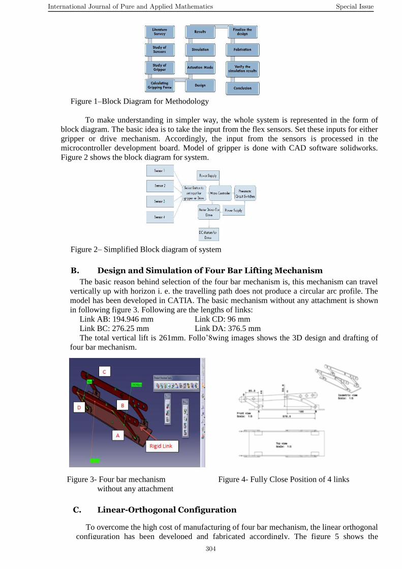
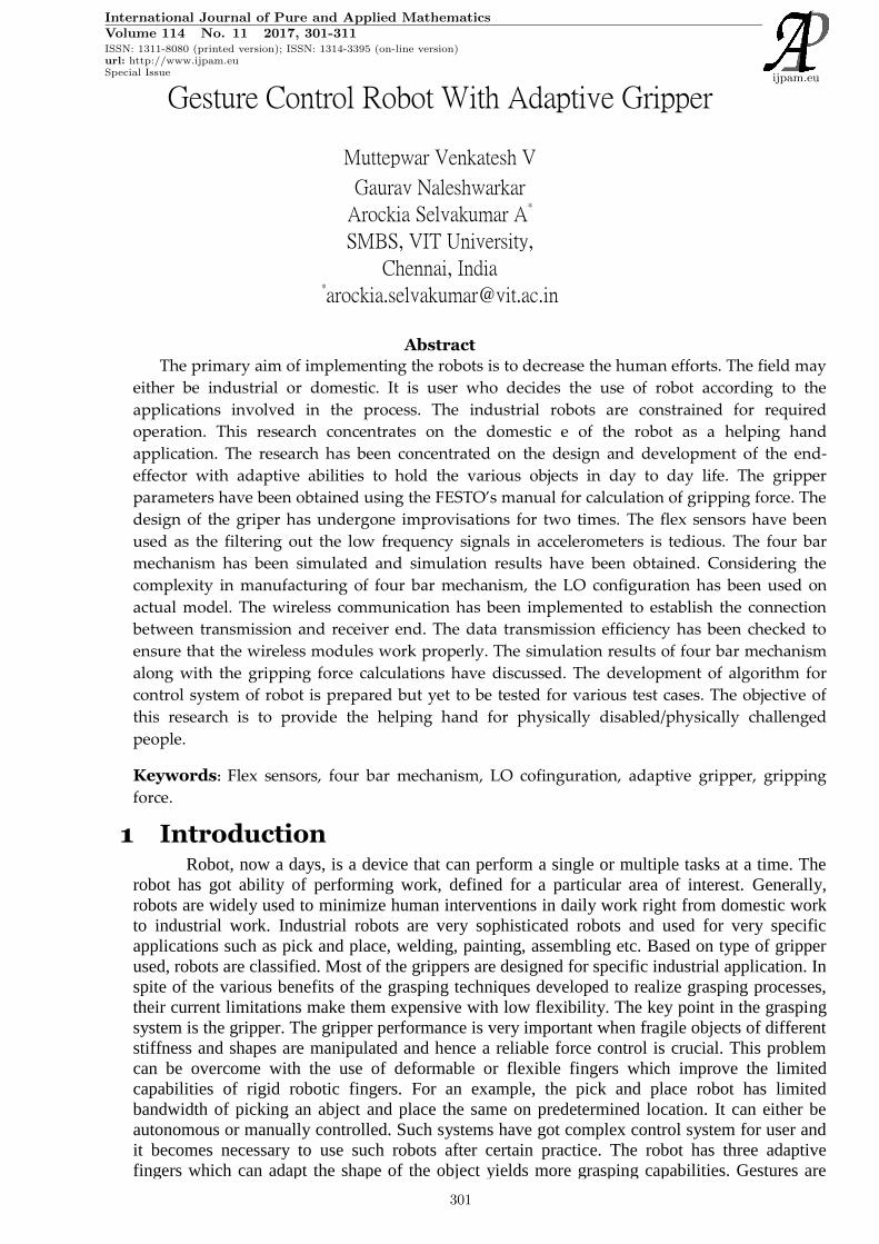
Figure 1–Block Diagram for Methodology
To make understanding in simpler way, the whole system is represented in the form of
block diagram. The basic idea is to take the input from the flex sensors. Set these inputs for either
gripper or drive mechanism. Accordingly, the input from the sensors is processed in the
microcontroller development board. Model of gripper is done with CAD software solidworks.
Figure 2 shows the block diagram for system.
Figure 2– Simplified Block diagram of system
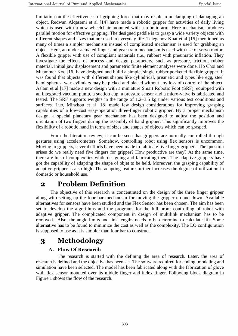
B. Design and Simulation of Four Bar Lifting Mechanism
The basic reason behind selection of the four bar mechanism is, this mechanism can travel
vertically up with horizon i. e. the travelling path does not produce a circular arc profile. The
model has been developed in CATIA. The basic mechanism without any attachment is shown
in following figure 3. Following are the lengths of links:
Link AB: 194.946 mm Link CD: 96 mm
Link BC: 276.25 mm Link DA: 376.5 mm
The total vertical lift is 261mm. Follo’8wing images shows the 3D design and drafting of
four bar mechanism.
Figure 3- Four bar mechanism Figure 4- Fully Close Position of 4 links
without any attachment
C. Linear-Orthogonal Configuration
To overcome the high cost of manufacturing of four bar mechanism, the linear orthogonal
configuration has been developed and fabricated accordingly. The figure 5 shows the
International Journal of Pure and Applied Mathematics Special Issue
304
drafting of L-O configuration. The linear movement is obtained with the use of the slider
element. The slider has got the travel of 25 cm. This 25 cm of travel is restricted to 23 cm to
prevent the slider from shocks and jerks at the free end. Orthogonal travel is the result of
piston in double acting cylinder. For testing purpose, the pressure has been increased from 1
bar to 4 bar which correspond to range 14.5 psi to 58 psi. For testing, the electro-pneumatic
setup has been used at 3 bar to observe the behaviour of pneumatic components like
solenoid controlled valves, double acting cylinder, relays etc. The on board pressure
required will be produced by small compressor that runs on 12 volt DC supply. The
compressor is capable of generating 250 psi pressure in continuous run of 15 minutes. The
pneumatic circuit has been developed and the same is simulated before implementing it on
actual practice. The time required to lift the end effector by orthogonal movement by 12 cm
is 1.5 seconds and 2 seconds for moving it down by controlling throttle during inlet and
outlet.
Figure 5- L-O Configuration designed in CATIA
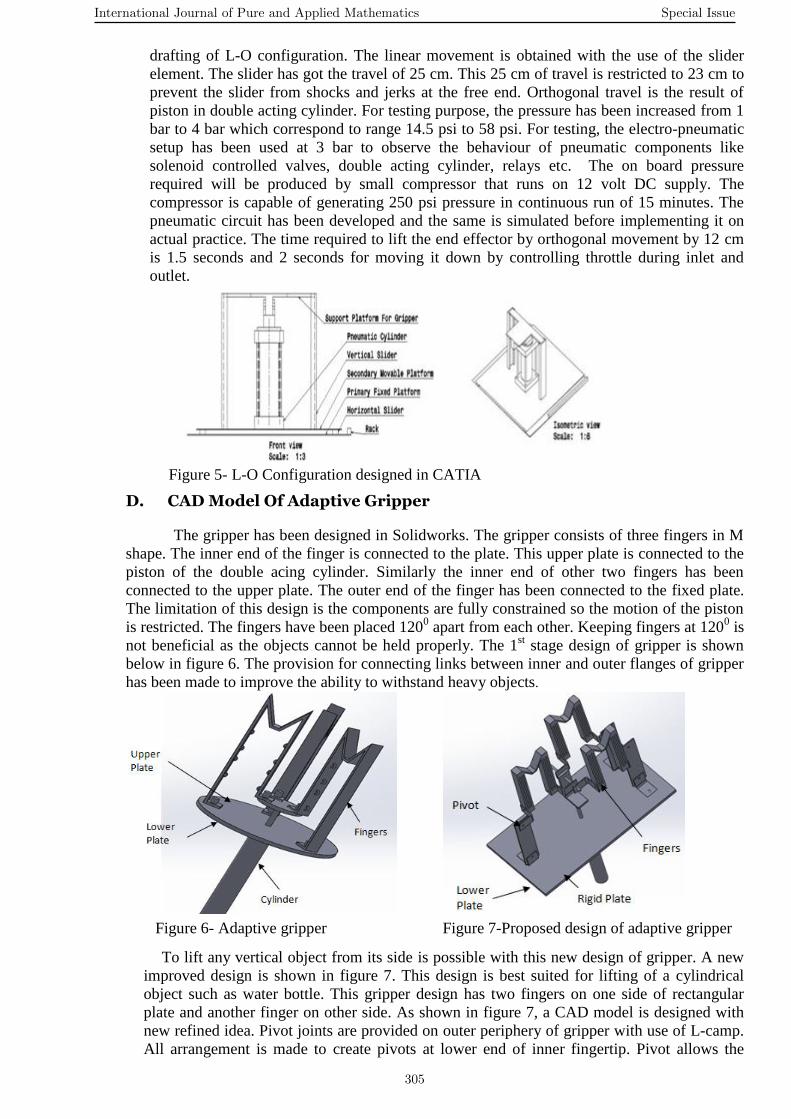
D. CAD Model Of Adaptive Gripper
The gripper has been designed in Solidworks. The gripper consists of three fingers in M
shape. The inner end of the finger is connected to the plate. This upper plate is connected to the
piston of the double acing cylinder. Similarly the inner end of other two fingers has been
connected to the upper plate. The outer end of the finger has been connected to the fixed plate.
The limitation of this design is the components are fully constrained so the motion of the piston
is restricted. The fingers have been placed 1200 apart from each other. Keeping fingers at 120
0 is
not beneficial as the objects cannot be held properly. The 1st stage design of gripper is shown
below in figure 6. The provision for connecting links between inner and outer flanges of gripper
has been made to improve the ability to withstand heavy objects.
Figure 6- Adaptive gripper Figure 7-Proposed design of adaptive gripper
To lift any vertical object from its side is possible with this new design of gripper. A new
improved design is shown in figure 7. This design is best suited for lifting of a cylindrical
object such as water bottle. This gripper design has two fingers on one side of rectangular
plate and another finger on other side. As shown in figure 7, a CAD model is designed with
new refined idea. Pivot joints are provided on outer periphery of gripper with use of L-camp.
All arrangement is made to create pivots at lower end of inner fingertip. Pivot allows the
International Journal of Pure and Applied Mathematics Special Issue
305
finger to grab the object. A metal rod piece has been used to join all L clamps at finger and is
attached to a big L clamp at piston. When the piston is retracted all assembly will be retracted
as they are connected. When piston retracts, then fingers will adapt shape of object. As hinges
are created to allow fingers to change their shape according to shape of object. L clamp will
rotate about a centre rod move finger inwards or outwards.
4 Fabrication and Testing
A. Fabrication
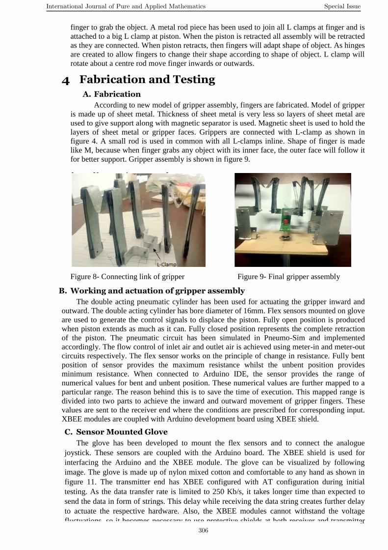
According to new model of gripper assembly, fingers are fabricated. Model of gripper
is made up of sheet metal. Thickness of sheet metal is very less so layers of sheet metal are
used to give support along with magnetic separator is used. Magnetic sheet is used to hold the
layers of sheet metal or gripper faces. Grippers are connected with L-clamp as shown in
figure 4. A small rod is used in common with all L-clamps inline. Shape of finger is made
like M, because when finger grabs any object with its inner face, the outer face will follow it
for better support. Gripper assembly is shown in figure 9.
Figure 8- Connecting link of gripper Figure 9- Final gripper assembly
B. Working and actuation of gripper assembly
The double acting pneumatic cylinder has been used for actuating the gripper inward and
outward. The double acting cylinder has bore diameter of 16mm. Flex sensors mounted on glove
are used to generate the control signals to displace the piston. Fully open position is produced
when piston extends as much as it can. Fully closed position represents the complete retraction
of the piston. The pneumatic circuit has been simulated in Pneumo-Sim and implemented
accordingly. The flow control of inlet air and outlet air is achieved using meter-in and meter-out
circuits respectively. The flex sensor works on the principle of change in resistance. Fully bent
position of sensor provides the maximum resistance whilst the unbent position provides
minimum resistance. When connected to Arduino IDE, the sensor provides the range of
numerical values for bent and unbent position. These numerical values are further mapped to a
particular range. The reason behind this is to save the time of execution. This mapped range is
divided into two parts to achieve the inward and outward movement of gripper fingers. These
values are sent to the receiver end where the conditions are prescribed for corresponding input.
XBEE modules are coupled with Arduino development board using XBEE shield.
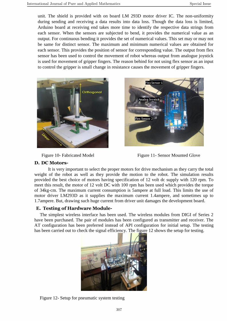
C. Sensor Mounted Glove
The glove has been developed to mount the flex sensors and to connect the analogue
joystick. These sensors are coupled with the Arduino board. The XBEE shield is used for
interfacing the Arduino and the XBEE module. The glove can be visualized by following
image. The glove is made up of nylon mixed cotton and comfortable to any hand as shown in
figure 11. The transmitter end has XBEE configured with AT configuration during initial
testing. As the data transfer rate is limited to 250 Kb/s, it takes longer time than expected to
send the data in form of strings. This delay while receiving the data string creates further delay
to actuate the respective hardware. Also, the XBEE modules cannot withstand the voltage
fluctuations, so it becomes necessary to use protective shields at both receiver and transmitter
International Journal of Pure and Applied Mathematics Special Issue
306
unit. The shield is provided with on board LM 293D motor driver IC. The non-uniformity
during sending and receiving a data results into data loss. Though the data loss is limited,
Arduino board at receiving end takes more time to identify the respective data strings from
each sensor. When the sensors are subjected to bend, it provides the numerical value as an
output. For continuous bending it provides the set of numerical values. This set may or may not
be same for distinct sensor. The maximum and minimum numerical values are obtained for
each sensor. This provides the position of sensor for corresponding value. The output from flex
sensor has been used to control the movement of robot whereas output from analogue joystick
is used for movement of gripper fingers. The reason behind for not using flex sensor as an input
to control the gripper is small change in resistance causes the movement of gripper fingers.
Figure 10- Fabricated Model Figure 11- Sensor Mounted Glove
D. DC Motors-
It is very important to select the proper motors for drive mechanism as they carry the total
weight of the robot as well as they provide the motion to the robot. The simulation results
provided the best choice of motors having specification of 12 volt dc supply with 120 rpm. To
meet this result, the motor of 12 volt DC with 100 rpm has been used which provides the torque
of 34kg-cm. The maximum current consumption is 5ampere at full load. This limits the use of
motor driver LM293D as it supplies the maximum current 1.4ampere, and sometimes up to
1.7ampere. But, drawing such huge current from driver unit damages the development board.
E. Testing of Hardware Module-
The simplest wireless interface has been used. The wireless modules from DIGI of Series 2
have been purchased. The pair of modules has been configured as transmitter and receiver. The
AT configuration has been preferred instead of API configuration for initial setup. The testing
has been carried out to check the signal efficiency. The figure 12 shows the setup for testing.
Figure 12- Setup for pneumatic system testing
International Journal of Pure and Applied Mathematics Special Issue
307
5 Results and Discussion The simulation results for four bar mechanism provided the vertical lift of 261mm. The
linear travel obtained is 250 mm whereas the orthogonal travel is 120 mm. The maximum and
minimum analogue input values of analogue joystick for x and y axes are 1023 and 0
respectively. These values are further mapped to 0 to 9 for purpose of processing and actuation
of motors. MATLAB simulation results have shown that the motor with 100 rpm will behave
best at 12 volts and it would provide sufficient torque. Taking this into consideration, the motor
with 100 rpm at 12 volt DC has been used which supplies the 34 Kg-cm torque. The pneumatic
system is adopted to ensure the better stability. Pressure of 3 bar is used while testing
pneumatic system which is the best suited for this setup. After actuation of gripper fingers,
displacement of one finger is 140 mm. The signal efficiency for serial communication is more
than 85% which indicates the normal behaviour of the XBEE module though there is lag
between transmission and receiving.
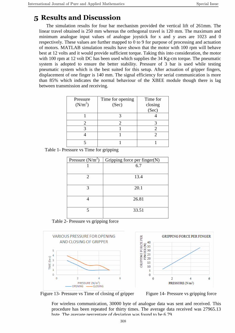
Pressure
(N/m2)
Time for opening
(Sec)
Time for
closing
(Sec)
1 3 4
2 2 3
3 1 2
4 1 2
5 1 1
Table 1- Pressure vs Time for gripping
Pressure (N/m2) Gripping force per finger(N)
1
6.7
2
13.4
3
20.1
4
26.81
5
33.51
Table 2- Pressure vs gripping force
Figure 13- Pressure vs Time of closing of gripper Figure 14- Pressure vs gripping force
For wireless communication, 30000 byte of analogue data was sent and received. This
procedure has been repeated for thirty times. The average data received was 27965.13
byte. The average percentage of deviation was found to be 6.79.
International Journal of Pure and Applied Mathematics Special Issue
308
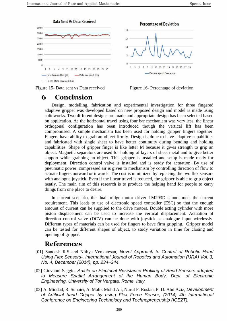
Figure 15- Data sent vs Data received Figure 16- Percentage of deviation
6 Conclusion Design, modelling, fabrication and experimental investigation for three fingered
adaptive gripper was developed based on new proposed design and model is made using
solidworks. Two different designs are made and appropriate design has been selected based
on application. As the horizontal travel using four bar mechanism was very less, the linear
orthogonal configuration has been introduced though the vertical lift has been
compromised. A simple mechanism has been used for holding gripper fingers together.
Fingers have ability to grab an object firmly. Design is done to have adaptive capabilities
and fabricated with single sheet to have better continuity during bending and holding
capabilities. Shape of gripper finger is like letter M because it gives strength to grip an
object. Magnetic separators are used for holding of layers of sheet metal and to give better
support while grabbing an object. This gripper is installed and setup is made ready for
deployment. Direction control valve is installed and is ready for actuation. By use of
pneumatic power, compressed air is given to mechanism by controlling direction of flow to
actuate fingers outward or inwards. The cost is minimized by replacing the two flex sensors
with analogue joystick. Even if the linear travel is reduced, the gripper is able to grip object
neatly. The main aim of this research is to produce the helping hand for people to carry
things from one place to desire.
In current scenario, the dual bridge motor driver LM293D cannot meet the current
requirement. This leads to use of electronic speed controller (ESC) so that the enough
amount of current can be supplied to the drive motors. Double acting cylinder with more
piston displacement can be used to increase the vertical displacement. Actuation of
direction control valve (DCV) can be done with joystick as analogue input wirelessly.
Different types of materials can be used for fingers to have firm gripping. Gripper model
can be tested for different shapes of object, to study variation in time for closing and
opening of gripper.
References [01] Sandesh R.S and Nithya Venkatesan, Novel Approach to Control of Robotic Hand
Using Flex Sensors-, International Journal of Robotics and Automation (IJRA) Vol. 3, No. 4, December (2014), pp. 234~244.
[02] Giovanni Saggio, Article on Electrical Resistance Profiling of Bend Sensors adopted to Measure Spatial Arrangement of the Human Body, Dept. of Electronic Engineering, University of Tor Vergata, Rome, Italy.
[03] A. Miqdad, R. Suhairi, A. Malik Mohd Ali, Nurul F. Roslan, P. D. Abd Aziz, Development of Artificial hand Gripper by using Flex Force Sensor, (2014) 4th International Conference on Engineering Technology and Technopreneuship (ICE2T).
International Journal of Pure and Applied Mathematics Special Issue
309
[04] Prashant Chaudhari, G. R. Phulay, Ravindra Patil A Review on Hand Gesture Recognition Systems, International Journal of Advanced Research in Computer Engineering and Technology (IJARCET) Volume 2, Issue 1, January (2013).
[05] A. Alice Linsie and J. Mangaiyarkarasi, Hand Gesture Recognition Using MEMS For Specially Challenged People, Journal of VLSI and Embedded Systems-IJVES, Vol 04, Issue 02; March - April (2013).
[06] Abidhusain Syed, Zamrrud Taj H. Agasbal, Thimmannagouday Melligeri, Bheemesh Gudur, Flex Sensor Based Robotic Arm Controller Using Micro Controller, Journal of Software Engineering and Applications, (2012), 5, 364-366.
[07] Petković, Dalibor, Mirna Issa, Nenad D. Pavlović, Lena Zentner, and Žarko Ćojbašić, Adaptive neuro fuzzy controller for adaptive compliant robotic gripper, Expert Systems with Applications 39, no. 18 (2012): 13295-13304.
[08] Widhiada, W., S. S. Douglas, I. D. Jenkinson, and J. B. Gomm. "Design and control of three fingers motion for dexterous assembly of compliant elements." International Journal of Engineering, Science and Technology 3, no. 6 (2011): 18-34.
[09] Amir Feizollahi, Pouya Sabetian, Design, Fabrication and Control of a Three-Finger Robotic Gripper, Journal and Year: First International Conference on Robot, Vision and Signal Processing( 2011).
[10] Kyoung Taik Park and Doo Hyung Kim, Robotic Handling Gripper Using Three Fingers, 9th International Conference on Ubiquitous Robots and Ambient Intelligence (URAI) Daejeon, Korea / November 26-29, (2012).
[11] Samavati, Farzad Cheraghpour, Amir Feizollahi, Pouya Sabetian, and S. Ali A. Moosavian, Design, Fabrication and Control of a Three-Finger Robotic Gripper, First International Conference on Robot, Vision and Signal Processing (RVSP), pp. 280-283. IEEE, (2011).
[12] Krishnaraju A, Ramkumar R, Lenin V R. Design of Three Fingered Robot-Gripper Mechanism, ISSN (Print): 2321-5747, Volume-3, Issue-3, (2015).
[13] Majid Tolouei-Rad and Peter Kalivitis, Development of an Autonomous Friction Gripper for Industrial Robots‖, World Academy of Science, Engineering and Technology, 5(10) pp. 249-254, (2011).
[14] Redwan Alqasemi, Sebastian Mahler and Rajiv Dubey, A Double Claw Robotic End-Effectors Design‖ ―University of South Florida‖ Conference Proceedings - Florida Conference on Recent Advances in Robotics and Robot Showcase, (2007).
[15] Telegenov, Kuat, Yedige Tlegenov, and Almas Shintemirov, A Low-Cost Open-Source 3-D-Printed Three-Finger Gripper Platform for Research and Educational Purposes, Access, IEEE 3 (2015): 638-647.
[16] Ho Choi and Muammer Koc, Design and Feasibility Tests of a Flexible Gripper based on inflatable Rubber Pockets‖, International Journal of Machine Tools and Manufacture, vol. 46 (10) pp. 1350-1361, (2006).
[17] Aslam, Dean M., and Girish D. Dangi, Design, fabrication and testing of a smart robotic foot, Robotics and Autonomous Systems 51, no. 2 (2005): 207-214.
[18] Luo, Minzhou, Giuseppe Carbone, Marco Ceccarelli, and Xianxiang Zhao, Analysis and design for changing finger posture in a robotic hand, Mechanism and Machine Theory 45, no. 6 (2010): 828-843.
[19] FESTO’s Manual for calculation of gripping force.
International Journal of Pure and Applied Mathematics Special Issue
310

311

312
Related Documents