GESTRA Steam Systems BA 46 BA 46-ASME BA 47 BA 47-ASME BAE 46... BAE 46...-ASME BAE 47... BAE 47...-ASME Installation Instructions / Product Information 818609-03 Continuous Blowdown Valve BA 46 / BA 46-ASME, PN 40/CL 150/300, DN 15-DN 50 BA 47 / BA 47-ASME, PN 63/CL 600, DN 25, 40, 50 BAE 46... / BAE 46...-ASME, PN 40/CL 150/300, DN 15-DN 50 BAE 47... / BAE 47...-ASME, PN 63/CL 600, DN 25, 40, 50 EN English

Welcome message from author
This document is posted to help you gain knowledge. Please leave a comment to let me know what you think about it! Share it to your friends and learn new things together.
Transcript

1
GESTRA Steam Systems
BA 46BA 46-ASME BA 47BA 47-ASMEBAE 46...BAE 46...-ASMEBAE 47...BAE 47...-ASMEInstallation Instructions / Product Information 818609-03Continuous Blowdown ValveBA 46 / BA 46-ASME, PN 40/CL 150/300, DN 15-DN 50BA 47 / BA 47-ASME, PN 63/CL 600, DN 25, 40, 50BAE 46... / BAE 46...-ASME, PN 40/CL 150/300, DN 15-DN 50BAE 47... / BAE 47...-ASME, PN 63/CL 600, DN 25, 40, 50
ENEnglish

2
ContentsPage
Important notes
Usage for the intended purpose ...............................................................................................................5Safety note ..............................................................................................................................................5PED (Pressure Equipment Directive) ........................................................................................................6ATEX (Hazardous Area) ............................................................................................................................6Note on the Declaration of Conformity / Manufacturer's Declaration ..............................................6
Explanatory Notes
Scope of supply ......................................................................................................................................7Description ..............................................................................................................................................8Function ................................................................................................................................................9
Technical Data
Name plate / marking ...........................................................................................................................10Dimensions BA 46, BA 47 ......................................................................................................................11Dimensions BAE 46..., BAE 47... ............................................................................................................12Dimensions of flanged ends (extract) .....................................................................................................13Dimensions of butt-weld ends (extract) .................................................................................................14Dimensions of socket-weld ends (extract) .............................................................................................14Pressure /Temperature Ratings & End Connections ...............................................................................15Materials ...............................................................................................................................................16Actuator ................................................................................................................................................16Capacity chart for DN 15 to 32, capacity ranges at a glance ..................................................................17Capacity chart for DN 15 to 32 , capacity range up to 310 kg/h ............................................................18Capacity chart for DN 15 to 32 , capacity range up to 1020 kg/h ..........................................................19Capacity chart for DN 15 to 32 , capacity range up to 2120 kg/h ..........................................................20Capacity chart for DN 40 and 50, capacity ranges at a glance ...............................................................21Capacity chart for DN 40 and 50, capacity range up to 1340 kg/h ........................................................22Capacity chart for DN 40 and 50, capacity range up to 4500 kg/h ........................................................23Capacity chart for DN 40 and 50, capacity range up to 6300 kg/h ........................................................24
Design
BA 46, BA 47 .........................................................................................................................................25BAE 46..., BAE 47... ...............................................................................................................................26Key .......................................................................................................................................................27
3
Contents Page
Installation
BA 46, BA 47, BAE 46..., BAE 47... .........................................................................................................28Flanged design ......................................................................................................................................28Butt-weld design ...................................................................................................................................28Socket-weld design ..............................................................................................................................28Heat treatment of welds ........................................................................................................................29Reposition control lever by 180 ° (if position of installation of BA 46 or BA 47 is unfavourable) ..............29Install sampling valve (if desired) ...........................................................................................................29
Electrical connection
Continuous blowdown valves BAE 46..., BAE 47... with actuator ............................................................30Factory settings for BAE 46..., BAE 47... ................................................................................................30
Commissioning procedure
BA 46, BA 47, BAE 46..., BAE 47... .........................................................................................................31Calculating the amount of boiler blowdown ...........................................................................................31Continuous blowdown valves BA 46, BA 47 without actuator .................................................................31Continuous blowdown valves BAE 46..., BAE 47... with actuator ............................................................31
Operation
BA 46, BA 47, BAE 46..., BAE 47... .........................................................................................................32Purging .................................................................................................................................................32
Emergency operation
BAE 46..., BAE 47... ...............................................................................................................................32
Maintenance
BA 46, BA 47, BAE 46..., BAE 47... .........................................................................................................33Changing packing and internals of BA 46, BA 47 ..................................................................................33BAE 46..., BAE 47... Changing packing and internals .............................................................................34Tightening torques ................................................................................................................................35Tools .....................................................................................................................................................35Removing internals ...............................................................................................................................36
- continued -

4
Contents - continued -
Page
Retrofitting
Mounting the actuator ...........................................................................................................................37Tightening torques ................................................................................................................................37Tools .....................................................................................................................................................37
Spare Parts
Spare parts list ......................................................................................................................................38
Parts for retrofitting
List of parts for retrofitting.....................................................................................................................39
Decommissioning
Disposal ................................................................................................................................................39

5
Important notes
Usage for the intended purpose
BA 46, BA 47:Use the continuous blowdown valves BA 46, BA 47 only for discharging boiler blowdown from steam boilers. Use the equipment only within the allowable pressure and temperature ratings and only if the chemical and corrosive influences on the equipment are taken into account.
BAE 46, BAE 46-1, BAE 46-3, BAE 46-3-1, BAE 47, BAE 47-1:Use continuous blowdown valve BAE 46..., BAE 47... only in conjunction with control units KS 90, LRR 1-40 or LRR 1-5 for the discharge of boiler blowdown from steam boilers. Use the equipment only within the allowable pressure and temperature ratings and only if the chemical and corrosive influences on the equipment are taken into account.
To ensure safe operation of the BAE 46..., BAE 47... only actuators named and specified by GESTRA may be installed on the valve. Specified and approved actuators are: ARIS EF 0.7, ARIS EF 0.7-1, ARIS EF 10 and ARIS EF 10-1.
Danger
The valve is under pressure during operation.When loosening flanged connections, sealing plugs or stuffing boxes, hot water and steam will escape.
The valve becomes hot during operation.Risk of severe burns and scalds to the whole body!Before carrying out any maintenance work on the valve or loosening flanged con-nections, stuffing box unions or sealing plugs make sure that all connected lines are depressurized (zero bar) and cooled down to room temperature (20 °C).
Sharp edges on internals present the danger of cuts to hands. Always wear industrial gloves when replacing the packing, valve seat or valve plug!
Danger of bruising! During operation moving internal parts can pinch one's hands or fingers, causing severe injuries. Do not touch moving parts. The continuous blowdown valves BAE 46..., BAE 47... are remote-controlled and can open and close abruptly.
The terminal strips of the actuator EF... are live during operation. This presents the danger of electric shock! Cut off power supply to the equipment before mounting or removing the equipment!
Safety note
The equipment must only be installed and commissioned by qualified and competent staff.
Retrofitting and maintenance work must only be performed by qualified staff who - through adequate training - have achieved a recognised level of competence.

6
PED (Pressure Equipment Directive)
The equipment fulfils the requirements of the Pressure Equipment Directive PED 97/23/EC. For use with fluids of group 2. With CE marking (apart from equipment that is excluded from the scope of the PED as specified in section 3.3).
Important Notes - continued -
Attention
The name plate specifies the technical features of the equipment. Do not commission or operate any item of equipment that does not bear its specific name plate.
ATEX (Hazardous Area)
The equipment BA 46, BA 47 can be used in potentially explosive areas, provided that the following notes are observed:The service fluid must not generate excessively high operating temperatures. Electrostatic charges that may be produced during operation must be discharged. The tight shut-off of the stuffing box must be ensured. The valve spindle must be able to move smoothly.Can be used in Ex zones 1, 2, 21, 22 (1999/92/EC), II 2 G/D c X.According to the European Directive 94/9/EC the equipment BAE 46..., BAE 47... must not be used in potentially explosive areas.For more information refer to our ATEX Declaration of Conformity.
Note on the Declaration of Conformity / Manufacturer's Declaration
For details on the conformity assessment according to the European Directives see our Declaration of Conformity or our Declaration of Manufacturer.The current Declaration of Conformity or Declaration of Manufacturer is available in the Internet under www.gestra.com documents or can be requested from us.
Manufacturer GESTRA AG Münchener Straße 77 28215 Bremen Germany Telefon +49 421 3503-0 Telefax +49 421 3503-393 E-mail [email protected] Web www.gestra.de
This declaration is no longer valid if modifications are made to the equipment without consultation with us.

7
Explanatory Notes
Scope of supply
BA 46 1 Continuous blowdown valve REAKTOMAT BA 46 1 Sample valve (supplied but not fitted) 1 Gasket A17 x 23 x 1.5 1 Installation manual GESTRA 1 Installation manual for sample valve
BA 47 1 Continuous blowdown valve REAKTOMAT BA 47 1 Sample valve (supplied but not fitted) 1 Gasket A17 x 23 x 1.5 1 Installation manual GESTRA 1 Installation manual for sample valve
Retrofitting kit for BA 46, BA 47 1 Electric actuator EF 0.7, EF 0.7-1, EF 10 or EF 10-1 1 Mounting kit for coupling / mounting bracket 1 Installation manual for ARIS actuator EF...
Spare parts 1 Kit according to spare parts list, page 38.
BAE 46... 1 Continuous blowdown valve REAKTOMAT BAE 46... 1 Sample valve (supplied but not fitted) 1 Gasket A17 x 23 x 1.5 1 Installation manual GESTRA 1 Installation manual for sample valve 1 Installation manual ARIS for actuator EF... 1 Manufacturer's Declaration
BAE 47... 1 Continuous blowdown valve REAKTOMAT BAE 47... 1 Sample valve (supplied but not fitted) 1 Gasket A17 x 23 x 1.5 1 Installation manual GESTRA 1 Installation manual for sample valve 1 Installation manual ARIS for actuator EF... 1 Manufacturer's Declaration

8
Description
Due to the continuous evaporation process in the steam boiler the density and hence the TDS (= Total Dissolved Solids) concentration of the boiler water is increased. If the TDS (= total dissolved solids) concentration exceeds the limit defined by pertinent regulations and dictated by the boiler manufacturer, foaming and priming occurs as the density of the boiler water increases, resulting in a carry-over of solids with vapour into steam lines and superheaters.
As a consequence, the operational safety is impaired and severe damage to boiler and tubes may occur. To keep the TDS concentration within admissible limits, a certain portion of boiler water must be removed continuously and/or periodically and fresh make-up water must be added to the boiler to compensate for the water lost through blowdown.
The continuous blowdown valves BA... and BAE... feature a specially designed and wear resistant nozzle stem that enters concentrically into a system of expansion chambers which are arranged one after the other, making these valves particularly suitable for the continuous discharge of boiler water at very high differential pressure. The continuous blowdown valves BA... and BAE... are suitable for operation in steam boiler plants according to TRD 604, EN 12952 and EN 12953.
BA 46 PN 40, manually operated
BA 47 PN 63, manually operated
BAE 46 PN 40, operated by the electric actuator EF 101)
BAE 46-1 PN 40, operated by the electric actuator EF 10-11)
BAE 46-3 PN 40, operated by the electric actuator EF 0.71)
BAE 46-3-1 PN 40, operated by the electric actuator EF 0.7-11)
BAE 47 PN 63, operated by the electric actuator EF 101)
BAE 47-1 PN 63, operated by the electric actuator EF 10-11)
EF 0.7 ARIS actuator with two position-controlled limit switches and an operating cam for intermediate positions
EF 0.7-1 ARIS actuator with two position-controlled limit switches and feedback potentiometer and an operating cam for intermediate positions
EF 10 ARIS actuator with two position-controlled limit switches and an operating cam for intermediate positions
EF 10-1 ARIS actuator with two position-controlled limit switches and feedback potentiometer and an operating cam for intermediate positions
1) Explosion-proof actuators or actuators powered by d. c. or three-phase current are available on request.
Explanatory Notes - continued -

9
Continuous blowdown valve REAKTOMAT BA 46, BA 47
To open or close the continuous blowdown valve BA 46, BA 47 use the control lever and to set the required amount of boiler blowdown use the scale. The required amount of boiler blowdown can be calculated with the aid of a formula or read off on a nomogram.
Continuous blowdown valve REAKTOMAT BA 46..., BA 47...
Due to the continuous evaporation process the electrical conductivity of the boiler water is increased. Electrical conductivity - as a result of the TDS (Total Dissolved Solids) content - is measured by a conduc-tivity electrode LRG 1.-..or a conductivity transmitter LRGT 1.-.. in conjunction with the industrial controller KS 90-1 or the conductivity controller LRR 1-.. . Depending on the adjusted setpoint the industrial controller KS 90-1 or the conductivity controller LRR 1-.. operates the electric actuator EF... and opens and closes the continuous blowdown valve.
The power flow towards the closing direction is transmitted via a coupling with integrated torsion spring. The coupling permits the actuator to travel a little bit further when the nozzle stem is pressed into the valve seat.
If a certain amount of boiler water is to be removed continuously via the continuous blowdown valve, make sure that the valve is permanently slightly open to ensure a steady flow of water (valve is in operating posi-tion). This operating position is adjustable and can be determined by using the capacity charts for the valve.The valve positions OPEN and CLOSED are limited by the cam-operated switch located in the actuator, the OPERATING POSITION is variably adjustable by means of an operating cam or a feedback potentiometer (EF 10-1, EF 0.7-1). However, if the actuator EF 10-1 or EF 0.7-1 is controlled by the conductivity controller LRR 1-52 or LRR 1-53 you can use the feedback potentiometer for indicating the valve position.
Function
Explanatory Notes - continued -

10
Fig. 1
Nominal pressure
Nominal sizeCode letter E
Max. admissible temperature
Name plate / marking
The temperature/pressure ratings are indicated on the body or on the name plate. For more informa-tion see GESTRA technical documents such as data sheets and the Technical Information.According to EN 19 the name plate or the specification on the body indicate the type and design: Name/logo of the manufacturer Type designation: Pressure class PN or Class Material number Max. temperature Max. pressure Direction of flow Stamp on valve body, e. g. specifies the quarter and the year of production (example: 4th quarter 2016)
416
Technical Data

11
DN 1
5-32
: 126
Fig. 2
Dimensions BA 46, BA 47
L
2018
0DN
15-
32: 1
72DN
40,
50:
213
DN 4
0, 5
0: 1
32
Technical Data - continued -

12
DN 1
5-32
: 126
Fig. 3
Dimensions BAE 46..., BAE 47...
L
2010
0DN
15-
32: 3
85DN
40,
50:
425
DN 4
0, 5
0: 1
32
Technical Data - continued -

13
Dimensions of flanged ends (extract)
L
DN EN 1092-1 (2001)PN 40
EN 1092-1 (2001)PN 63
[inch] ½ ¾ 1 1¼ 1½ 2 1 1½ 2[mm] 15 20 25 32 40 50 25 40 50
D 95 105 115 140 150 165 140 170 180b 16 18 18 18 18 20 24 26 26k 65 75 85 100 110 125 100 125 135g 45 58 68 78 88 102 68 88 102l 14 14 14 18 18 18 18 22 22n 4 4 4 4 4 4 4 4 4L 150 150 160 180 200 230 190 220 250
[kg]*) 4.7/8.8 5.3/9.4 5.8/9.9 7.1/11.2 10.7/14.8 12.5/16.6 7.1/11.2 10.7/14.8 12.5/16.6*) Weight BA 4... / Weight BAE 4...
L
DN ASME B16.5 Class 150
[inch] ½ ¾ 1 1¼ 1½ 2[mm] 15 20 25 32 40 50
D 88.9 98.4 107.9 117.5 127.0 152.4b 11.1 12.7 14.3 15.9 17.5 19.0k 60.3 69.8 79.4 88.9 98.4 120.6g 34.9 42.9 50.8 63.5 73.0 92.1l 15.9 15.9 15.9 15.9 15.9 19.0n 4 4 4 4 4 4L 150 150 160 180 230 230
[kg]*) 4.7/8.8 5.3/9.4 5.8/9.9 7.1/11.2 10.7/14.8 12.5/16.6*) Weight BA 4... / Weight BAE 4...
L
DN ASME B16.5 Class 300
ASME B16.5Class 600
[inch] ½ ¾ 1 1¼ 1½ 2 1 1½ 2[mm] 15 20 25 32 40 50 25 40 50
D 95.2 117.5 123.8 133.3 155.6 165.1 123.8 155.6 165.1b 14.3 15.9 17.5 19.0 20.6 22.2 17.5 22.2 25.4k 66.7 82.5 88.9 98.4 114.3 127 88.9 114.3 127g 34.9 42.9 50.8 63.5 73.0 92.1 50.8 73.0 92.1l 15.9 19.0 19.0 19.0 22.2 19.0 19.0 22.2 19.0n 4 4 4 4 4 4 4 4 4L 150 150 160 180 230 230 216 216 250
[kg]*) 4.7/8.8 5.3/9.4 5.8/9.9 7.1/11.2 10.7/14.8 12.5/16.6 7.1/11.2 10.7/14.8 12.5/16.6*) Weight BA 4... / Weight BAE 4... Other designs available on request. Special dimensions, sizes and materials for end connections on request.
∅ l
∅ l
∅ l
Technical Data - continued -

14
Dimensions of butt-weld ends (extract)
Dimensions of socket-weld ends (extract)
L
DN ASME B16.25, Schedule 40ASME B36.10
ASME B16.25, Schedule 80ASME B36.10
[inch] ½ ¾ 1 1¼ 1½ 2 1 1½ 2[mm] 15 20 25 32 40 50 25 40 50
d2 22 28 34 43 49 61 34 49 61d1 15.7 20.9 26.6 35.1 40.9 52.5 24.3 38.1 49.3
for pipe 21.3x2.8 26.7x2.9 33.4x3.4 42.2x3.6 48.3x3.7 60.3x3.9 33.4x4.5 48.3x5.1 60.3x5.5L 200 200 200 200 250 250 200 250 250
[kg]*) 4.1/8.2 4.7/8.8 4.7/8.8 5.4/9.5 8.9/13.0 10.2/14.3 4.7/8.8 8.9/13.0 10.2/14.3*) Weight BA 4.. / Weight BAE 4... Other designs available on request. Special dimensions, sizes and materials for end connections on request.
DN DIN EN 12760, ASME B16.11Class 3000
[inch] ½ ¾ 1 1¼ 1½ 2[mm] 15 20 25 32 40 50
d2 35 40 45 55 62 75d1 21.8 27.3 34.1 42.8 48.8 61.3b 10 13 13 13 13 16
for pipe 21.3/21.3 26.9/26.7 33.7/33.4 42.4/42.2 48.3/48.3 60.3/60.3L 200 200 200 200 250 250
[kg]*) 3.7/7.8 3.9/8.0 4.2/8.3 5.1/9.2 8.3/12.4 9.5/13.6*) Weight BA 4... / Weight BAE 4... Other designs available on request. Special dimensions, sizes and materials for end connections on request.
d 1 d 2
bL
L
DN DIN 3239-1, series 1DIN 2559-2
DIN 3239-1, series 2DIN 2559-2
[inch] ½ ¾ 1 1¼ 1½ 2 1 1½ 2[mm] 15 20 25 32 40 50 25 40 50
d2 22 28 34 43 49 61 34 49 61d1 17.3 22.0 28.5 37.0 43.0 54.5 28.5 42.5 54.5
for pipe 21.3x2.0 26.9x2.3 33.7x2.6 42.4x2.6 48.3x2.6 60.3x2.9 33.7x2.6 48.3x2.9 60.3x2.9L 200 200 200 200 250 250 200 250 250
[kg]*) 4.1/8.2 4.7/8.8 4.7/8.8 5.4/9.5 8.9/13.0 10.2/14.3 4.7/8.8 8.9/13.0 10.2/14.3*) Weight BA 4..., / Weight BAE 4...
Technical Data - continued -

15
Pressure /Temperature Ratings & End Connections
BA 4..., BAE 4...-ASME, Flanged B16.5 Class 150, butt-weld ends B16.25, socket-weld ends B16.11, Class 3000
pmax (max. pressure) [barg] 14
ts (boiling point) [°C] 198
pmax (max. pressure) [psi]g 203
ts (boiling point) [°F] 388
Calculated in accordance with ASME B16.34
BA 4..., BAE 4...-ASME, Flanged B16.5 Class 300, butt-weld ends B16.25, socket-weld ends B16.11, Class 3000
pmax (max. pressure) [barg] 42
ts (boiling point) [°C] 254
pmax (max. pressure) [psi]g 609
ts (boiling point) [°F] 489
Calculated in accordance with ASME B16.34
BA 4..., BAE 4...-ASME, Flanged B16.5 Class 600, butt-weld ends B16.25, socket-weld ends B16.11, Class 3000
pmax (max. pressure) [barg] 55
ts (boiling point) [°C] 271
pmax (max. pressure) [psi]g 800
ts (boiling point) [°F] 520
Calculated in accordance with ASME B16.34
BA 46, BAE 46, Flanged PN 40, EN 1092-1 (2013), 1.0460*)
pmax (max. pressure) [barg] 31
ts (boiling point) [°C] 238Calculated in accordance with DIN EN 12516-2, * material according to AD 2000
BA 46, BAE 46, Flanged PN 40, EN 1092-1 (2013), A 105
pmax (max. pressure) [barg] 31
ts (boiling point) [°C] 238Calculated in accordance with DIN EN 12516-2
BA 47, BAE 47, Flanged PN 63 / PN 100, EN 1092-1 (2013), 1.0460*)
pmax (max. pressure) [barg] 47
ts (boiling point) [°C] 261Calculated in accordance with DIN EN 12516-2, *) material according to AD 2000
BA 47, BAE 47, Flanged PN 63 / PN 100, EN 1092-1 (2013), A 105
pmax (max. pressure) [barg] 47
ts (boiling point) [°C] 261Calculated in accordance with DIN EN 12516-2
Technical Data - continued -

16
Materials
Type BA 4..., BAE 4... BA 4... ASME, BAE 4... ASME
Designation DIN / EN ASTM
Body 1.0460 A105
Nozzle stem 1.4021 A 276 Grade 420
Seat and stage sleeves 1.4104 430F
Locking screw A2-70 A192 CL 2B-BB
Sealing plug 1.7225 A193 B7
EF 0.7 (-1) EF 10 (-1)Dimensions Width 86 86
Height 133 133
Length 153 153
Voltage 230 V 230 V
optional 24 V DC
120 V 50/60 Hz x x
3Ph 400 V 50/60 Hz
Protection IP 65 65
optional up to
Power consumption 4 VA 4 VA
Tightening torque 15 Nm 30 Nm
Ambient temperature –15 / +60°C –15 / +60°C
Ex version possible yes yes
Feedback Potentiometer / resolution in ° only for EF..-1 320° 320°
4-20 mA available yes yes
For more information please refer to installation manual of the manufacturer.
Actuator
Technical Data - continued -

17
Fig. 4
Capacity chart for DN 15 to 32, capacity ranges at a glanceHo
t wat
er c
apac
ity [k
g/h]
Position of control lever
Differential pressure
Technical Data - continued -

18
Fig. 5
Capacity chart for DN 15 to 32 , capacity range up to 310 kg/hHo
t wat
er c
apac
ity [k
g/h]
Position of control lever
Differential pressure
Technical Data - continued -
19
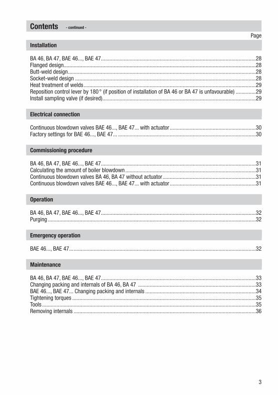
Fig. 6
Capacity chart for DN 15 to 32 , capacity range up to 1020 kg/hHo
t wat
er c
apac
ity [k
g/h]
Position of control lever
Differential pressure
Technical Data - continued -

20
Fig. 7
Capacity chart for DN 15 to 32 , capacity range up to 2120 kg/hHo
t wat
er c
apac
ity [k
g/h]
Position of control lever
Differential pressure
Technical Data - continued -
21
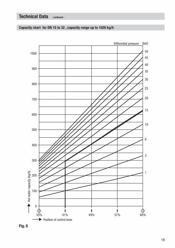
Fig. 8
Capacity chart for DN 40 and 50, capacity ranges at a glanceHo
t wat
er c
apac
ity [k
g/h]
Position of control lever
Differential pressure
Technical Data - continued -

22
Fig. 9
Technical Data
Capacity chart for DN 40 and 50, capacity range up to 1340 kg/hHo
t wat
er c
apac
ity [k
g/h]
Position of control lever
Differential pressure
- continued -

23
Fig. 10
Technical Data
Capacity chart for DN 40 and 50, capacity range up to 4500 kg/hHo
t wat
er c
apac
ity [k
g/h]
Position of control lever
Differential pressure
- continued -

24
Fig. 11
Technical Data
Capacity chart for DN 40 and 50, capacity range up to 6300 kg/hHo
t wat
er c
apac
ity [k
g/h]
Position of control lever
Differential pressure
- continued -

25
Fig. 12
Design
BA 46, BA 47
2
e
b
d
1
a
fg
h
i
j
k
c
43
5
6
7
8
9
9
0

26
Design
BAE 46..., BAE 47...
q
p
r
Fig. 13
s
a
n
m
o
- continued -

27
Design
1 Stuffing box screw
2 Scale plate
3 Stuffing box gland
4 Disk spring (3 pieces)
5 Spring sleeve
6 Packing with 4 wiper rings
7 Guide sleeve
8 Wear resisting sleeve
9 Stage bushing
0 Seat bushing
a Valve body
b Name plate
c ATEX marking
d GasketA17 x 23 x 1.5
e Sealing plug (connection for sample valve)
f Locking screw
g Gasket C6 x 10 x 1.5 (DN 15-32) C10 x 16 x 1.5 (DN 40,50)
h Nozzle stem
i Scale
j Hexagon nut
k Control lever
l Actuator
m Compression spring
n Thrust washer
o Grooved dowel pin ISO 8742
p Mounting bracket
q Checking pin
r Hexagon screw with washer
s Coupling
Key
- continued -

28
Socket-weld design
1. Observe position of installation. The control lever k must be free to move!2. Observe direction of flow. The arrow indicating the flow direction is on the valve body. 3. Consider space required for servicing the equipment. When the continuous blowdown valve is
installed a minimum space of at least 180mm is required for removing the equipment or for the subsequent installation of the actuator!
4. Remove plastic plugs. They are only used as transit protection.5. Clean socket-weld ends.6. Arc-weld trap only manually (welding processes 111 and 141 in accordance with ISO 4063) or use
gas welding process (welding process 3 in accordance with ISO 4063).
Installation
BA 46, BA 47, BAE 46..., BAE 47...
When installing the continuous blowdown valve make sure that the flow arrow matches the flow direction. The blowdown take-off point must be located below the low level mark and close to the steam outlet of the steam boiler. The continuous blowdown valve can be installed in horizontal and vertical pipes.The continuous blowdown valve is supplied ready for installation and without or with an actuator mounted.Before commissioning read the technical documentation provided by the manufacturer of the actuator and store the document together with the installation manual "BA 46, BA 47, BAE 46..., BAE 47..." in a sheltered place. The continuous blowdown valve is delivered with a sampling valve (not installed). Attach the sampling valve only to the correct connection of the continuous blowdown valve, following the rules of the state of the technical art! Before commissioning read the technical documentation provided by the manufacturer of the sampling valve and store the document together with the installation manual "BA 46, BA 47, BAE 46..., BAE 47..." in a sheltered place.
Flanged design
1. Observe position of installation. The control lever k must be free to move!2. Observe direction of flow. The arrow indicating the flow direction is on the valve body. 3. Consider space required for servicing the equipment. When the continuous blowdown valve is
installed a minimum space of at least 180mm is required for removing the equipment or for the subsequent installation of the actuator!
4. Remove plastic plugs. They are only used as transit protection.5. Clean seating surfaces of both flange faces.6. Install the continuous blowdown valve.
Butt-weld design
1. Observe position of installation. The control lever k must be free to move!2. Observe direction of flow. The arrow indicating the flow direction is on the valve body. 3. Consider space required for servicing the equipment. When the continuous blowdown valve is
installed a minimum space of at least 180mm is required for removing the equipment or for the subsequent installation of the actuator!
4. Remove plastic plugs. They are only used as transit protection.5. Clean butt-weld ends.6. Arc-weld trap only manually (welding processes 111 and 141 in accordance with ISO 4063) or use
gas welding process (welding process 3 in accordance with ISO 4063).
Attention
Make sure that the inclination of the actuator does not exceed 90 ° when installed!
29
Installation
Heat treatment of welds
After welding the continuous blowdown valve in place a heat treatment of the welds may be required (stress-relief annealing to DIN EN 10052).The heat treatment must be restricted to the immediate area of the weld.The internals of the continuous blowdown valve need not be removed before the heat treatment.
Attention
Only qualified welders certified e. g. according to EN 287-1 may weld the continuous blowdown valve into pressurised lines.
Reposition control lever by 180 ° (if position of installation of BA 46 or BA 47 is unfavourable)
If the position of installation is unfavourable (flow from right to left), it may be necessary to reposition the control lever by 180 ° so that the scale plate can be seen.
1. Take heed of danger note on page 5!2. Unscrew the hexagon nut j and detach the control lever k with the aid of the pulling device.3. Undo stuffing box screws 1, remove the stuffing box gland 3 and scale plate 2. Turn scale plate
by 180 ° and put it back in place.4. Mount stuffing box gland 3 and screw in stuffing box 1.5. Screw out nozzle stem h by half a turn and tighten stuffing box screws 1.6. Turn nozzle stem h into the closed position, applying a torque of 7 Nm. Put control lever k in
place and align scale i with the scale plate 2such that the diamond-shaped marker "0" is in the middle of the scale plate.
7. Screw hexagon nut j onto the threaded part of the nozzle stem h and tighten while holding the control lever.
Please refer to the table "Torques required for tightening".
Install sampling valve (if desired)
1. Unscrew sealing plug e and remove gasket d.
2. Observe installation instructions of the sampling valve.
2. Install sample valve in compliance with the accredited state of the technical art.
- continued -

30
Continuous blowdown valves BAE 46..., BAE 47... with actuator
Apart from the positions OPEN and CLOSED you can select an OPERATING POSITION for the actuators EF 0.7.. and EF 10... The OPERATING POSITION allows the continuous discharge of a defined amount of boiler water. The OPERATING POSITION can be adjusted in the actuator by means of a switching cam. For the adjustment follow the instructions given in the attached installation manual for the Actuator EF.... The actuators EF 10-1 and EF 0.7-1 have a feedback potentiometer 0 - 1000 ohm. For the adjustment follow the instructions given in the attached installation manual for the actuator EF....
The electrical connection of the actuator EF... must be established as specified in the attached instal-lation manual "Actuator EF ...".
Factory settings for BAE 46..., BAE 47...
The default settings of the actuators EF 0.7 and EF 10 are: CLOSED (scale position "0"), OPERATING POSITION (scale position "1") and "OPEN" (scale position "4"). Fig. 4, Fig. 8The OPERATING POSITION allows the continuous discharge of a defined amount of boiler water. The OPERATING POSITION can be adjusted in the actuator by means of a switching cam. For more information on the adjustment refer to the installation manual for the Actuator EF.... The default settings of the actuators EF 10-1 and EF 0.7-1 are: CLOSED (scale position "0") and OPEN (scale position"4"). The default factory setting of the feedback potentiometer is 50 Ω ± 5 Ω for scale position "0" and 940 Ω ± 5 Ω for scale position "4“.
Electrical connection
Danger of bruising! During operation moving internals can pinch one's hands or fingers, causing severe injuries. Do not touch moving parts. The continuous blowdown valves BAE 46..., BAE 47... are remote-controlled and can open and close abruptly.
The terminal strips of the actuator EF... are live during operation. This presents the danger of electric shock! Cut off power supply to the equipment before mounting or removing the equipment!
Danger

31
Commissioning procedure
Danger of burns! The control lever of the continuous blowdown valve and the coupling of the actuator are hot during operation. Touching the control lever and the coupling presents the risk of severe burns to hands and arms. Always wear thermally insulated and heat resistant safety gloves when operating the valves.
Danger
Make sure that the flanged connections of the BA 46, BA 47, BAE 46..., BAE 47...are tightly bolted together and leakproof. The stuffing box gland 3 must be re-tightened if leaks occur.
BA 46, BA 47, BAE 46..., BAE 47...
Continuous blowdown valves BA 46, BA 47 without actuator
The amount of boiler blowdown dictated by the operating conditions can be adjusted by means of the control lever on the continuous blowdown valve . For more information please refer to the capacity charts on pages 17 to 24.
Continuous blowdown valves BAE 46..., BAE 47... with actuator
Use the control equipment KS 90, LRR 1-40, LRR 1-5x to set the required TDS level of the boiler water. Please compare the resulting valve positions (see scale on control lever) with the values indicated in the capacity charts on pages 17 to 24.
Attention
As the stuffing box screws are tightened the break-out force and the frictional forces of the nozzle stem are increased!
The break-away force and the friction force of the nozzle stem must not exceed the maximum operating force of the actuator.!
Excessive fastening of the stuffing box screws impairs the correct functioning of the continuous blowdown valve and can cause jamming of the nozzle stem.
If the nozzle stem is blocked, the continuous blowdown valve can no longer open, regulate or close.
Calculating the amount of boiler blowdown
Boiler water to be discharged
A = Q · S K – SA = Amount of boiler water to be discharged [kg/h]Q = Boiler capacity [kg/h]S = Conductivity of feedwater [µs/cm]K = Admissible conductivity of boiler water [µs/cm]
Example Differential pressure: 15 bar Nominal size of continuous blowdown valve: DN 20Boiler capacity: Q = 10000 kg/hConductivity of feedwater: S = 100 µs/cmAdmissible conductivity of boiler water: K = 3000 µs/cmBoiler water to be discharged: A ≈ 345 kg/hof which approx.10 % by means of continuous blowdown: ≈ 35 kg/hBoiler blowdown: A1 ≈ 310 kg/hSet control lever according to scale to an opening of 41 %. Fig. 6

32
Emergency operation
BAE 46..., BAE 47...
1. Cut off power supply to actuator and lift coupling s manually by approx. 1 cm. Fig. 132. Set the control lever k to the desired flowrate by using the scale i. Fig. 13
Operation
Danger of burns! The control lever of the continuous blowdown valve and the coupling of the actuator are hot during operation. Touching the manual lever and the coupling pre-sents the risk of severe burns to hands and arms. Always wear thermally insulated and heat resistant safety gloves when operating the valves.
Danger
Make sure that the flanged connections of the BA 46, BA 47, BAE 46..., BAE 47...are tightly bolted to-gether and leakproof. The stuffing box gland 3 must be re-tightened if leaks occur.
BA 46, BA 47, BAE 46..., BAE 47...
Attention
As the stuffing box screws are tightened the break-out force and the frictional forces of the nozzle stem are increased!
The break-away force and the friction force of the nozzle stem must not exceed the maximum operating force of the actuator.!
Excessive fastening of the stuffing box screws impairs the correct functioning of the continuous blowdown valve and can cause jamming of the nozzle stem.
If the nozzle stem is blocked, the continuous blowdown valve can no longer open, regulate or close.
Completely open the blowdown valve once a day for a short period of time. For this purging process take the operating limits of the plant into consideration.
Purging

33
The continuous blowdown valves BA 46, BA 47, BAE 46... and BAE 47... do not require any special maintenance. Depending on the quality of the boiler water it might be necessary to service the valve every one or two years.
Maintenance
01. Observe the danger note on page 5!02. Unscrew the hexagon nut j and detach the control lever k with the aid of the pulling device.03. Undo stuffing box screws 1, remove stuffing box gland 3, scale plate 2, disk springs 4 and
spring sleeve 5.04. Unscrew nozzle stem h and pull it out of the valve body.05. Unscrew locking screw f and remove gasket g. 06. Unscredw sealing plug e and remove gasket d.07. Use a brass drift punch d = 14.8 mm to force out the internals 6 to 0. Fig. 1408. Clean and, if necessary, exchange valve body a and internals.09. Apply glue "Loctite 620" to seat bushing 0 ® and put it in place. Insert stage bushing 9.10. Align wearing bushing 8 in such a way that the groove is on the longitudinal axis of the locking
screw f.11. Screw in the locking screw f together with gasket g and tighten it when cold.12. Align wearing bushing 7 in such a way that the groove is on the longitudinal axis of the locking
screw f. Fig. 1213. Insert new wiper rings and packing rings 6 as shown in Fig. 1214. Apply lubricant WINIX 2010 to the thread and the sealing surface of the nozzle stem.15. Insert nozzle stem h and screw it into the guide sleeve by two turns.16. Insert spring sleeve 5 and disk springs 4 in the shown sequence.17. Put scale plate 2 and stuffing box gland 3 in place and tighten stuffing box screws 1 slightly.18. Screw out nozzle stem h by half a turn and tighten stuffing box screws 1.19. Turn nozzle stem h into the closed position, applying a torque of 7 Nm. Put control lever k in
place and align scale i with the scale plate 2 such that the diamond-shaped marker "0" is in the middle of the scale plate
20. Screw hexagon nut j onto the threaded part of the nozzle stem and tighten while holding the control lever.
21. Screw sealing plug e together with gasket d into the valve body and tighten or screw in the sampling valve with the gasket according to the instructions given by the manufacturer.
Please refer to the table "Torques required for tightening".
Changing packing and internals of BA 46, BA 47
BA 46, BA 47, BAE 46..., BAE 47...
WINIX® 2010 is a registered trademark of WINIX GmbH, NorderstedtLOCTITE® 620 is a registered trademark of HENKEL KGaA, Düsseldorf

34
01. Observe the danger note on page 5!02. Cut off power supply to the actuator l.03. Use hexagon screws r and remove actuator and coupling s.04. Unscrew the hexagon nut j and detach the control lever k with the aid of the pulling device.05. Undo stuffing box screws 1, remove stuffing box gland 3, scale plate 2, disk springs 4 and
spring sleeve 5.06. Unscrew nozzle stem h and pull it out of the valve body.07. Unscrew locking screw f and remove gasket g. 08. Unscrewed sealing plug e and remove gasket d.09. Use a brass drift punch d = 14.8 mm to force out the internals 6 to 0. Fig. 1410. Clean and, if necessary, exchange valve body a and internals.11. Apply glue "Loctite 620" to seat bushing 0 ® and put it in place. Insert stage bushing 9.12. Align wearing bushing 8 in such a way that the groove is on the longitudinal axis of the locking
screw f.13. Screw in the locking screw f together with gasket g and tighten it when cold.14. Align wearing bushing 7 in such a way that the groove is on the longitudinal axis of the locking
screw f. Fig. 1215. Insert new wiper rings and packing rings 6 as shown in Fig. 1216. Apply lubricant WINIX 2010 to the thread and the sealing surface of the nozzle stem.17. Insert nozzle stem h and screw it into the guide sleeve by two turns.18. Insert spring sleeve 5 and disk springs 4 in the shown sequence.19. Put scale plate 2 and stuffing box gland 3 in place and tighten stuffing box screws 1 slightly.20. Screw out nozzle stem h by half a turn and tighten stuffing box screws 1.21. Turn nozzle stem h into the closed position, applying a torque of 7 Nm. Put control lever k in place
and align scale i with the scale plate 2 such that the diamond-shaped marker "0" is in the mid-dle of the scale plate
22. Screw hexagon nut j onto the threaded part of the nozzle stem and tighten while holding the con-trol lever.
23. Screw sealing plug e together with gasket d into the valve body and tighten or screw in the sam-pling valve with the gasket according to the instructions given by the manufacturer.
24. Put coupling s onto control lever k and fix the mounting bracket p and actuator l to the valve body using the hexagon screws r. Adjust control lever until the coupling makes contact.
Maintenance
BAE 46..., BAE 47... Changing packing and internals
WINIX® 2010 is a registered trademark of WINIX GmbH, NorderstedtLOCTITE® 620 is a registered trademark of HENKEL KGaA, Düsseldorf
- continued -

35
Combination spanner A. F. 7 mm, DIN 3113, Form B Combination spanner A. F. 10 mm, DIN 3113, Form B Combination spanner A. F. 13 mm, DIN 3113, Form B Combination spanner A. F. 16 mm, DIN 3113, Form B Combination spanner A. F. 17 mm, DIN 3113, Form B Torque spanner (US: torque wrench) 1-12 Nm, ISO 6789 Torque spanner (US: torque wrench) 8-40 Nm, ISO 6789 Torque spanner (US: torque wrench) 80-400 Nm, ISO 6789 Punch 14,8x220, CuZn (brass) Hammer 300g, DIN 1041 Self-centering pulling device, size 0
Tools
Tightening torques
Item Continuous blowdown valvesTorque for tightening [Nm]
DN 15-32: DN 40, 50
1 BA 46, BA 47, BAE 46..., BAE 47... 7 11
e BA 46, BA 47, BAE 46..., BAE 47... 130
f BA 46, BA 47, BAE 46..., BAE 47... 5 11
h BA 46, BA 47, BAE 46..., BAE 47... 7
j BA 46, BA 47, BAE 46..., BAE 47... 20
r BAE 46..., BAE 47... DIN EN 10052 30
All torques indicated in the table are based at a room temperature of 20 °C.
25. Align the actuator, making sure that the coupling s is level on the control lever. Fasten hexagon screws r.
26. Adjust the switching cams for OPEN, CLOSED and OPERATING POSITION or, if fitted, the feedback potentiometer according to the attached installation manual Actuators EF... .
27. Set the switching cam for CLOSED in the actuator such that the torque checking pin q is to the right but does not touch the checking hole. The closing torque in this position is 10 Nm. Fig. 13
Please refer to the table "Torques required for tightening".
Maintenance
BAE 46..., BAE 47... Changing packing and internals
- continued -
- continued -

36
Maintenance
Removing internals
Fig. 14
- continued -

37
Retrofitting
Mounting the actuator
GESTRA continuous blowdown valves BA 46 and BA 47 can be retrofitted with an actuator EF... (BAE 46..., BAE 47...).
Danger of bruising! During operation moving internal parts can pinch one's hands or fingers, causing severe injuries. Do not touch moving parts. The continuous blowdown valves BAE 46..., BAE 47... are remote-controlled and can open and close abruptly. The terminal strips of the actuator EF... are live during operation. This presents the danger of electric shock! Cut off power supply to the equipment before mounting or removing the equipment!
Danger
1. Observe the installation instructions of the actuator manufacturer.2. Attach compression spring m, thrust washer n and grooved dowel pin o to actuator l EF... .
Fig. 133. Put coupling s onto control lever k and fix the mounting bracket p and actuator l to the valve
body using the hexagon screws r. Adjust control lever until the coupling makes contact.4. Align the actuator, making sure that the coupling s is level on the control lever. Fasten hexagon
screws r as specified in the table below Tightening torques.5. Adjust the switching cams for OPEN, CLOSED and OPERATING POSITION or, if fitted, the feedback
potentiometer according to the attached installation manual Actuators EF... .6. Set the switching cam for CLOSED in the actuator such that the torque checking pin q is to the right
but does not touch the checking hole. The closing torque in this position is 10 Nm. Fig. 137. Remove the ATEX marking c from the valve body a. BAE 46..., BAE 47... must not be used in
potentially explosive areas.
Tightening torques
Combination spanner A. F. 13 mm, DIN 3113, Form B Torque spanner (US: torque wrench) 1-12 Nm, ISO 6789 Hammer 300g, DIN 1041
Tools
All torques indicated in the table are based at a room temperature of 20 °C.
Item Continuous blowdown valves Torque for tightening [Nm]
r BAE 46..., BAE 47... 30

38
Spare Parts
Spare parts list
Item Designation
Stock code # Stock code #
BA 46BA 47
BAE 46...BAE 47...
6 dg 5
Packing & gasket kit, DN 15 to DN 32:
1 packing ring 15 x 23 x 8, 4 wiper rings, 1 gasket C 6 x 10 x 1.5, 1 gasket A 17 x 23 x 1.5
335702 335702
6 dg 5
Packing & gasket kit, DN 40 and DN 50:
1 packing ring 18 x 28 x 10, 4 wiper rings, 1 gasket C 10 x 16 x 1.5, 1 gasket A 17 x 23 x 1.5
335704 335704
6 78 90 dg h
Complete spare parts kit, DN 15 to DN 32:
1 nozzle stem, 1 seat bushing, 2 stage bushings, 1 wear resistant sleeve, 1 guide sleeve, 1 packing ring 15 x 23 x 8, 4 wiper rings, 1 gasket C 6 x 10 x 1.5, 1 gasket A 17 x 23 x 1.5
335703 335703
6 78 90 dg h
Complete spare parts kit, DN 40 and DN 50:
1 nozzle stem, 1 seat bushing, 2 stage bushings, 1 wear resistant sleeve, 1 guide sleeve, 1 packing ring 18 x 28 x 10, 4 wiper rings, 1 gasket C 10 x 16 x 1.5, 1 gasket A 17 x 23 x 1.5
335705 335705
l Actuator EF 0.7, 230 V, 50/60 Hz (for BAE 46-3) 336806
l Actuator EF 0.7-1, 230 V, 50/60 Hz (for BAE 46-3-1) 336807
l Actuator EF 10, 230 V, 50/60 Hz (for BAE 46, BAE 47) 336808
l Actuator EF 10-1, 230 V, 50/60 Hz (for BAE 4...-1) 336813
Explosion-proof actuators or actuators powered by d. c. or three-phase current are available on request.

39
Decommissioning
Risk of severe burns and scalds to the whole body!Before loosening flanged connections, stuffing box unions or sealing plugs make sure that all connected lines are depressurized (zero bar) and cooled down to room temperature (20 °C).The terminal strips of the actuator EF... are live during operation. This presents the danger of electric shock! Cut off power supply to the equipment before mounting or removing the equipment!
Danger
Parts for retrofitting
List of parts for retrofitting
Item DesignationStock code # Stock code #
BA 46BA 47
BAE 46... BAE 47...
lmnoprs
1 actuator EF 0.7, 230 V, 50/60 Hz, 1 mounting bracket, 1 assembly set for coupling, 3 hexagon screws (for BAE 46-3)
336810
1 actuator EF 0.7, 230 V, 50/60 Hz, 1 mounting bracket, 1 assembly set for coupling, 3 hexagon screws (for BAE 46-3-1)
336811
1 actuator EF 10, 230 V, 50/60 Hz, 1 mounting bracket, 1 assembly set for coupling, 3 hexagon screws (for BAE 46..., BAE 47...)
336812
1 actuator EF 10-1, 230 V, 50/60 Hz, 1 mounting bracket, 1 assembly set for coupling, 3 hexagon screws (for BAE 4...-1)
336813
1 mounting bracket, 1 assembly set for coupling, 3 hexagon screws (without actuator l)
335769
Disposal
Dismantle the equipment and separate the waste materials (see Technical Data).For the disposal of the equipment observe the pertinent legal regulations concerning waste disposal.

40818609-03/06-2016cm (808708-05) · GESTRA AG · Bremen · Printed in Germany
Agencies all over the world:
www.gestra.com
GESTRA AGMünchener Straße 77 28215 BremenGermanyTelefon +49 421 3503-0 Telefax +49 421 3503-393E-mail [email protected] www.gestra.de
Related Documents