― ― 139 Gerber-hinged Prestressed-concrete Box-girder Made Continuous — Suzuta Bridge — ゲルバーヒンジを有するプレストレストコンクリート箱桁橋の連続化 ― 鈴田橋 ― * ** *** **** * Naofumi ANDO, P.E.Jp: Sumitomo Mitsui Construction Co., Ltd. 安藤 直文,技術士(総合技術監理部門,建設部門):三井住友建設(株) ** Ryoichi ODO: West Nippon Expressway Co., Ltd. 尾堂 良一:西日本高速道路(株) *** Daizo KOMATANI: West Nippon Expressway Co., Ltd. 駒谷 大三:西日本高速道路(株) **** Yuji KUMAGAI: Sumitomo Mitsui Construction Co., Ltd. 熊谷 裕司:三井住友建設(株) Contact: [email protected] Keywords: Gerber hinge, continuous bridge, alkali silica reaction (ASR), re-anchor DOI: 10.11474/JPCI.NR.2018.139 Synopsis Suzuta Bridge on the Nagasaki Expressway is a 7-span continuous rigid-frame prestressed-concrete (PC) box- girder bridge that has a distinctive hinged structure (a Gerber hinge) at a point a quarter of the way along the center span. The bridge was observed to have deteriorated because of the alkali silica reaction (ASR), with markedly advanced deterioration around the hinged section, which takes in large amounts of water from the bridge deck. The work reported herein involved a radical repair to cut, remove, and recast part of the main girder near the hinge to remove the hinge and make the girder continuous. While the main girder was removed, structural safety of the whole bridge was ensured by temporary struts and temporary tendons to hold the girder in position. Structural Data Structure: 7-span continuous rigid-frame PC box- girder bridge (hinged) Bridge Length: 484.8m (54.3 + [email protected] + 54.3m) Width: 10.95m (both inbound and outbound lanes) History: Completed in 1978; seismic retrofitting in 2008; made continuous (this work) in 2012 Owner: West Nippon Expressway Co., Ltd. Design and Construction (this work): Sumitomo Mitsui Construction Co., Ltd. Location: Nagasaki Prefecture, Japan. 1. Introduction Suzuta Bridge on the Nagasaki Expressway is located approximately half way between the Isahaya and Omura interchanges (ICs). It crosses the gentle valley formed by the Suzuta River at a height of about 30m Isahaya IC→ ←Omura IC JR Omura Line National Route 34 ←Inbound lane Outbound lane→ 168 m 145 m 4-span continuous PC box girder 7-span continuous rigid frame PC box girder 485 m 3-span continuous PC box girder Hinge Plan Elevation M M R R R R M M F M M M M M F M M P7 P8 P10 P9 P4 P3 P6 P5 A1 P1 P2 P12 P13 A2 P11 2.1 m 4.2 m Hinge Fig.1 General view

Welcome message from author
This document is posted to help you gain knowledge. Please leave a comment to let me know what you think about it! Share it to your friends and learn new things together.
Transcript
― ―139
Gerber-hinged Prestressed-concrete Box-girder Made Continuous — Suzuta Bridge —
ゲルバーヒンジを有するプレストレストコンクリート箱桁橋の連続化― 鈴田橋 ―
* ** *** ****
* Naofumi ANDO, P.E.Jp: Sumitomo Mitsui Construction Co., Ltd.安藤 直文,技術士(総合技術監理部門,建設部門):三井住友建設(株)
** Ryoichi ODO: West Nippon Expressway Co., Ltd.尾堂 良一:西日本高速道路(株)
*** Daizo KOMATANI: West Nippon Expressway Co., Ltd.駒谷 大三:西日本高速道路(株)
**** Yuji KUMAGAI: Sumitomo Mitsui Construction Co., Ltd.熊谷 裕司:三井住友建設(株)
Contact: [email protected]: Gerber hinge, continuous bridge, alkali silica reaction (ASR), re-anchorDOI: 10.11474/JPCI.NR.2018.139
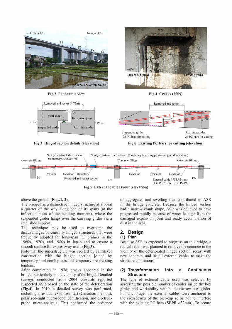
SynopsisSuzuta Bridge on the Nagasaki Expressway is a 7-span continuous rigid-frame prestressed-concrete (PC) box-girder bridge that has a distinctive hinged structure (a Gerber hinge) at a point a quarter of the way along the center span. The bridge was observed to have deteriorated because of the alkali silica reaction (ASR), with markedly advanced deterioration around the hinged section, which takes in large amounts of water from the bridge deck.The work reported herein involved a radical repair to cut, remove, and recast part of the main girder near the hinge to remove the hinge and make the girder continuous. While the main girder was removed, structural safety of the whole bridge was ensured by temporary struts and temporary tendons to hold the girder in position.
Structural DataStructure: 7-span continuous rigid-frame PC box- girder bridge (hinged)Bridge Length: 484.8m (54.3 + [email protected] + 54.3m)Width: 10.95m (both inbound and outbound lanes)History: Completed in 1978; seismic retrofitting in 2008; made continuous (this work) in 2012Owner: West Nippon Expressway Co., Ltd.Design and Construction (this work): Sumitomo Mitsui Construction Co., Ltd.Location: Nagasaki Prefecture, Japan.
1. IntroductionSuzuta Bridge on the Nagasaki Expressway is located approximately half way between the Isahaya and Omura interchanges (ICs). It crosses the gentle valley formed by the Suzuta River at a height of about 30m
Isahaya IC→←Omura IC
JR Omura LineNational Route 34
←Inbound lane
Outbound lane→
168 m 145 m 4-span continuous PC box girder 7-span continuous rigid frame PC box girder 485 m 3-span continuous PC box girder
Hinge
Plan
Elevation
M M R R R R M MF M M M
M M F M M
P7 P8 P10 P9P4 P3 P6P5 A1 P1 P2 P12 P13 A2P11
2.1 m 4.2 m
Hinge
Fig.1 General view
― ―140
above the ground (Figs.1, 2).The bridge has a distinctive hinged structure at a point a quarter of the way along one of its spans (at the inflection point of the bending moment), where the suspended girder hangs over the carrying girder via a steel shoe support.This technique may be used to overcome the disadvantages of centrally hinged structures that were frequently adopted for long-span PC bridges in the 1960s, 1970s, and 1980s in Japan and to ensure a smooth surface for expressway users (Fig.3).Note that the superstructure was erected by cantilever construction with the hinged section joined by temporary steel comb plates and temporary prestressing tendons.After completion in 1978, cracks appeared in the bridge, particularly in the vicinity of the hinge. Detailed surveys conducted from 2004 onwards reported suspected ASR based on the state of the deterioration (Fig.4). In 2010, a detailed survey was performed, including a residual expansion test (Canadian method), polarized-light microscope identification, and electron-probe micro-analysis. This confirmed the presence
of aggregates and swelling that contributed to ASR in the bridge concrete. Because the hinged section had a narrow crank shape, ASR was believed to have progressed rapidly because of water leakage from the damaged expansion joint and ready accumulation of dust in the area.
2. Design(1) PlanBecause ASR is expected to progress on this bridge, a radical repair was planned to remove the concrete in the vicinity of the deteriorated hinged section, recast with new concrete, and install external cables to make the structure continuous.
(2) Transformation into a Continuous Structure
The type of external cable used was selected by assessing the possible number of cables inside the box girder and workability within the narrow box girder. For anchorage, the external cables were anchored to the crossbeams of the pier-cap so as not to interfere with the existing PC bars (SBPR φ32mm). To secure
Fig.2 Panoramic view Fig.4 Cracks (2009)
Steel shoe
Expansion joint
Removed and recast (4.75m)
Carrying girder Suspended girder P7→ ←P6
Fig.3 Hinged section details (elevation) Fig.6 Existing PC bars for cutting (elevation)
22 PC bars for cutting Carrying girderSuspended girder
24 PC bars for cutting
Removed and recast
P8P7P6
Concrete filling Newly constructed crossbeam (temporary fastening prestressing tendon section)
Deviator Removed and recast section External cable 19S15.2 mm
(4 in P8-P7-P6, 6 in P7-P6)
Concrete filling Newly constructed crossbeam (temporary strut section) Concrete filling
Deviator Deviator Deviator Deviator Deviator
Fig.5 External cable layout (elevation)
― ―141
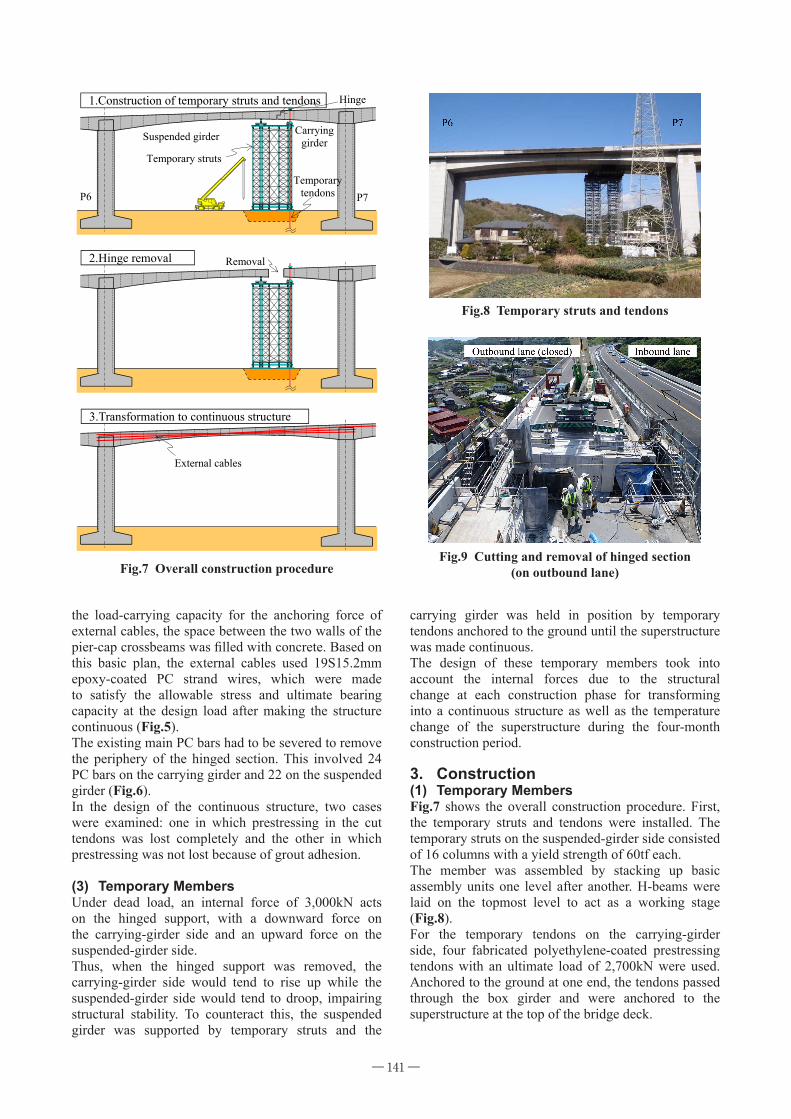
carrying girder was held in position by temporary tendons anchored to the ground until the superstructure was made continuous.The design of these temporary members took into account the internal forces due to the structural change at each construction phase for transforming into a continuous structure as well as the temperature change of the superstructure during the four-month construction period.
3. Construction(1) Temporary MembersFig.7 shows the overall construction procedure. First, the temporary struts and tendons were installed. The temporary struts on the suspended-girder side consisted of 16 columns with a yield strength of 60tf each.The member was assembled by stacking up basic assembly units one level after another. H-beams were laid on the topmost level to act as a working stage (Fig.8).For the temporary tendons on the carrying-girder side, four fabricated polyethylene-coated prestressing tendons with an ultimate load of 2,700kN were used. Anchored to the ground at one end, the tendons passed through the box girder and were anchored to the superstructure at the top of the bridge deck.
the load-carrying capacity for the anchoring force of external cables, the space between the two walls of the pier-cap crossbeams was filled with concrete. Based on this basic plan, the external cables used 19S15.2mm epoxy-coated PC strand wires, which were made to satisfy the allowable stress and ultimate bearing capacity at the design load after making the structure continuous (Fig.5).The existing main PC bars had to be severed to remove the periphery of the hinged section. This involved 24 PC bars on the carrying girder and 22 on the suspended girder (Fig.6).In the design of the continuous structure, two cases were examined: one in which prestressing in the cut tendons was lost completely and the other in which prestressing was not lost because of grout adhesion.
(3) Temporary MembersUnder dead load, an internal force of 3,000kN acts on the hinged support, with a downward force on the carrying-girder side and an upward force on the suspended-girder side.Thus, when the hinged support was removed, the carrying-girder side would tend to rise up while the suspended-girder side would tend to droop, impairing structural stability. To counteract this, the suspended girder was supported by temporary struts and the
Temporary struts
Suspended girder
Hinge
P7P6
1.Construction of temporary struts and tendons
External cables
3.Transformation to continuous structure
2.Hinge removal
Carryinggirder
Temporarytendons
Removal
Fig.7 Overall construction procedure
Fig.8 Temporary struts and tendons
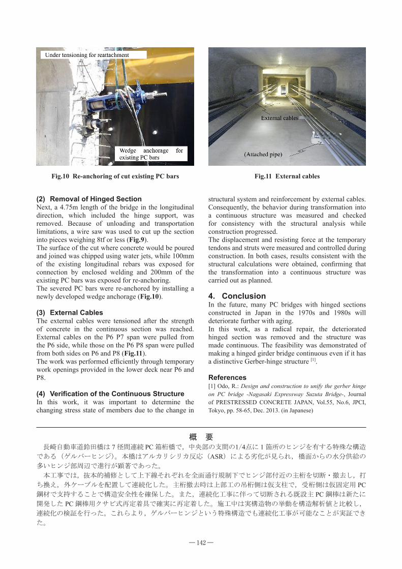
Fig.9 Cutting and removal of hinged section(on outbound lane)
― ―142
概 要 長崎自動車道鈴田橋は 7 径間連続 PC 箱桁橋で,中央部の支間の1/4点に 1 箇所のヒンジを有する特殊な構造
である(ゲルバーヒンジ)。本橋はアルカリシリカ反応(ASR)による劣化が見られ,橋面からの水分供給の
多いヒンジ部周辺で進行が顕著であった。
本工事では,抜本的補修として上下線それぞれを全面通行規制下でヒンジ部付近の主桁を切断・撤去し,打
ち換え,外ケーブルを配置して連続化した。主桁撤去時は上部工の吊桁側は仮支柱で,受桁側は仮固定用 PC鋼材で支持することで構造安全性を確保した。また,連続化工事に伴って切断される既設主 PC 鋼棒は新たに
開発した PC 鋼棒用クサビ式再定着具で確実に再定着した。施工中は実構造物の挙動を構造解析値と比較し,
連続化の検証を行った。これらより,ゲルバーヒンジという特殊構造でも連続化工事が可能なことが実証でき
た。
(2) Removal of Hinged SectionNext, a 4.75m length of the bridge in the longitudinal direction, which included the hinge support, was removed. Because of unloading and transportation limitations, a wire saw was used to cut up the section into pieces weighing 8tf or less (Fig.9).The surface of the cut where concrete would be poured and joined was chipped using water jets, while 100mm of the existing longitudinal rebars was exposed for connection by enclosed welding and 200mm of the existing PC bars was exposed for re-anchoring.The severed PC bars were re-anchored by installing a newly developed wedge anchorage (Fig.10).
(3) External CablesThe external cables were tensioned after the strength of concrete in the continuous section was reached. External cables on the P6 P7 span were pulled from the P6 side, while those on the P6 P8 span were pulled from both sides on P6 and P8 (Fig.11).The work was performed efficiently through temporary work openings provided in the lower deck near P6 and P8.
(4) VerificationoftheContinuousStructureIn this work, it was important to determine the changing stress state of members due to the change in
structural system and reinforcement by external cables. Consequently, the behavior during transformation into a continuous structure was measured and checked for consistency with the structural analysis while construction progressed.The displacement and resisting force at the temporary tendons and struts were measured and controlled during construction. In both cases, results consistent with the structural calculations were obtained, confirming that the transformation into a continuous structure was carried out as planned.
4. ConclusionIn the future, many PC bridges with hinged sections constructed in Japan in the 1970s and 1980s will deteriorate further with aging.In this work, as a radical repair, the deteriorated hinged section was removed and the structure was made continuous. The feasibility was demonstrated of making a hinged girder bridge continuous even if it has a distinctive Gerber-hinge structure [1].
References[1] Odo, R.: Design and construction to unify the gerber hinge on PC bridge -Nagasaki Expressway Suzuta Bridge-, Journal of PRESTRESSED CONCRETE JAPAN, Vol.55, No.6, JPCI, Tokyo, pp. 58-65, Dec. 2013. (in Japanese)
Fig.10 Re-anchoring of cut existing PC bars Fig.11 External cables
Related Documents