GEOLOGICAL • GEOTECHNICAL • ENVIRONMENTAL • ENGINEERING Intégrale is a trading name of Integrale Limited Registered Office: The Granary, Chewton Fields, Ston Easton, Somerset, BA3 4BX, United Kingdom Company Registration No. 2855366 England VAT Reg. No. 609 7402 37 Suite 7, Westway Farm Business Park Wick Road, Bishop Sutton, Somerset BS39 5XP United Kingdom Tel: 01275 333036 www.integrale.uk.com REPORT NO. 19106, February 2020 Proposed Redevelopment Jerrings Hall Farm Tanworth Lane Shirley Solihull West Midlands B90 4DX GEOTECHNICAL REPORT

Welcome message from author
This document is posted to help you gain knowledge. Please leave a comment to let me know what you think about it! Share it to your friends and learn new things together.
Transcript
GEOLOGICAL • GEOTECHNICAL • ENVIRONMENTAL • ENGINEERING Intégrale is a trading name of Integrale Limited Registered Office: The Granary, Chewton Fields, Ston Easton, Somerset, BA3 4BX, United Kingdom Company Registration No. 2855366 England VAT Reg. No. 609 7402 37
Suite 7, Westway Farm Business Park Wick Road, Bishop Sutton, Somerset BS39 5XP United Kingdom Tel: 01275 333036 www.integrale.uk.com
REPORT NO. 19106, February 2020
Proposed Redevelopment
Jerrings Hall Farm
Tanworth Lane
Shirley
Solihull
West Midlands
B90 4DX
GEOTECHNICAL REPORT

GEOLOGICAL • GEOTECHNICAL • ENVIRONMENTAL • ENGINEERING
Integrale Limited, Suite 7, Westway Farm Business Park, Wick Road, Bishop Sutton, Somerset, BS39 5XP, United Kingdom
Tel: 01275 333036 www.integrale.uk.com
Registered Office: The Granary, Chewton Fields, Ston Easton, Somerset, BA3 4BX, United Kingdom Company Registration No. 2855366 England
Geotechnical Report Proposed Redevelopment Jerrings Hall Farm Tanworth Lane Shirley Solihull West Midlands B90 4DX Client: Sanderson Weatherall LLP Intégrale Report No. 19106, February 2020
Signature/Date
Project Co-ordinator & Report Preparation:
Joseph Begaj
Mentor Consultant & Advice:
Andrew Harris & Gareth Thomas
Technical Director & Report Approved:
Dr Kay Boreland
Final Check: Millie Lewis
CONFIDENTIALITY STATEMENT
This report is addressed to and may be relied upon by the following:
Sanderson Weatherall LLP
30 Queen Square Bristol
BS1 4ND
Integrale Limited has prepared this report solely for the use of the client named above. Should any other parties wish to use or rely upon the contents of this report, written approval must be sought from
Integrale Limited. An assignment fee may then be charged.
LIST OF CONTENTS
– EXECUTIVE SUMMARY –
1.0 INTRODUCTION 1
2.0 THE SITE 2
2.1 Location and Description 2
2.2 Published Geology 3
2.3 British Geological Survey Mapping 3
2.3.1 BGS Previous Investigation Records 3
2.4 Outline History 4
2.5 Radon Risk Information 4
3.0 GROUND INVESTIGATION 5
3.1 Trial Pitting 5
3.1.1 Mechanical Trial Pitting 5
3.1.2 Manual Trial Pitting 5
3.2 Infiltration Testing 5
3.2.1 BRE 365 (2007) – Conventional Soakaway Testing 5
3.2.2 Building Regulations Part H (2010) – Percolation Testing 5
3.2.3 Dual Ring Infiltrometer Testing 5
3.3 Groundwater and Soils Gas Standpipe Installations and Monitoring 5
3.4 Geotechnical Laboratory Testing 5
3.5 Referencing 6
4.0 GROUND & GROUNDWATER CONDITIONS 7
4.1 Summary of Strata Encountered 7
4.2 Strata Properties 7
4.2.1 Made Ground / Topsoil 7
4.2.2 Glacial Deposits 8
4.3 Groundwater 8
4.4 Ground Gas 9
5.0 GEOTECHNICAL CONSIDERATIONS 10
5.1 Scheme Details & Structural Loadings 10
5.2 Site Preparation and Earthworks 10
5.3 Foundations and Ground Floor Slabs 10
5.3.1 Typical Ground Conditions 10
5.3.2 Design Bearing Pressures for Footings or Reinforced Slabs 11
5.3.3 Piles 11
5.3.4 Ground Floor Slabs 11
5.3.5 Formation Inspections 11
5.4 Pavement Design 11
5.5 Protection of Buried Concrete 12
5.6 Drainage Considerations 12
5.7 Contamination Considerations 13

FIGURES 1. Site Plan
APPENDICES
A. Site Location B. Site Description & Photographs C. Trial Pit Logs & Sketches D. Soakaway Analyses E. Percolation Analyses F. Dual Ring Infiltration Analyses G. Results of Geotechnical Laboratory Testing H. Results of Gas & Groundwater Monitoring I. Proposed Redevelopment

Suite 7, Westway Farm Business Park Wick Road, Bishop Sutton, Somerset, BS39 5XP, United Kingdom
Tel: 01275 333036 www.integrale.uk.com
GEOLOGICAL • GEOTECHNICAL • ENVIRONMENTAL • ENGINEERING
Intégrale is a trading name of Integrale Limited. Registered Office: The Granary, Chewton Fields, Ston Easton, Somerset, BA3 4BX United Kingdom Company Registration No. 2855366 England VAT Reg. No. 609 7402 37
EXECUTIVE SUMMARY
Geotechnical Report 19106 – Jerrings Hall Farm, Tanworth Lane, Solihull, B90 4DX
The Jerrings Hall Farm site is being converted for the relocation of an independent specialist school, The Island Project. The existing Grade II Listed buildings are being retained with proposed construction of a new single storey, modular teaching building south of the existing courtyard a further modular building to the north and remodelled access, new car parking and associated works. Geological mapping reports Glacial Till blanketing the site which is overlain by Glaciolacustrine Deposits along the northern and eastern boundaries. The superficial deposits are underlain by Mercia Mudstone of Triassic Age. Old maps indicate that the site has been predominantly in its current configuration since the late-1800s with alterations to the site boundaries in the intervening period. A pond was mapped within the south central area along the site boundary since the late 1800s until the late 1970s/early ‘80s and recent renovation work has been undertaken on various buildings surrounding the courtyard. A historical trial pit excavated c.200m west of the site proved interbedded sandy Clay and clayey Sand to c.3.2m depth, with wall collapse recorded from shallow depth. Groundwater seepage was encountered at c.1.3m depth. The investigation has proven a discontinuous veneer of Topsoil/Hardstanding over localised thin existing Made Ground. The Glacial Soils beneath are variable in composition but generally clayey, locally sandy. The clayey soils are soft, soft to firm or firm. The granular Glacial Soils are initially loose, rapidly becoming medium dense. The Mercia Mudstone bedrock was not proven. The groundwater table appears to be at c.0.8-1.0m depth. The Glacial Soils are capable of supporting reinforced spread foundations. Design bearing pressures of 100kN/m2 and 75kN/m2 for 1m and 2m wide foundations respectively within the firm clayey Glacial Till; increasing to 125kN/m2 and 100kN/m2 for 1m and 2m wide foundations respectively for the loose to medium dense Glacial Till. The bearing pressures given take into account the likelihood of a shallow groundwater table. A piled foundation is another option. Lightly loaded ground floor slabs may be designed as ground bearing (assuming a ‘weak’ formation) onto natural Glacial Till soils. Design CBR values of at least 2-3% and 4-5% onto the clayey and granular Glacial Till respectively are feasible. Preliminary monitoring and analysis indicates:
- Design Sulphate Class of DS-1 and ACEC Class of AC-1 are recommended for buried concrete; - New water pipes require protection; - No radon protection measures are required; - Surplus spoil should be removed to a suitably licenced tip.
Jerrings Hall Farm, Shirley, Solihull, 19106, February 2020 1
1.0 INTRODUCTION The Jerrings Hall Farm site is being converted from its former residential use for the relocation of a specialist education school, The Island Project. The existing Grade II Listed buildings are being retained with proposed construction new single storey, modular teaching buildings north and south of the existing courtyard with remodelled access, new car parking and associated works. Sanderson Weatherall LLP, the project managers, are overseeing the redevelopment of the site. Their consulting engineers are Stability Consulting Limited, with Clive Onions Limited consulting on certain aspects of the drainage strategy. The project architects are CMS Group Limited. Integrale Limited (Intégrale) have been commissioned to undertake a ground investigation and complete a geotechnical report. The investigation scope was determined by both the consulting and drainage engineers in liaison with Intégrale. This interpretative report summarises generic desk studies, describes the scope of fieldworks, laboratory testing and monitoring, discusses the ground and groundwater conditions encountered, and gives advice on foundations and other geotechnical aspects. A formal desk study has not been commissioned. This is not a contaminated land report.

Jerrings Hall Farm, Shirley, Solihull, 19106, February 2020 2
2.0 THE SITE 2.1 Location and Description As shown in Appendix A, the site is located off Tanworth Lane (B4102), approximately 4.5km SW of Solihull town centre. It has a central Ordnance Survey Grid Reference of E421111 N276302 and postcode B90 4DX. Notes describing the site were prepared during the site visit and are included as Appendix B, together with typical photographs. The main features and pertinent aspects on the site and immediately adjacent land are summarised below and annotated on Figure 1: Current Use Residential (currently unoccupied). Site Area & Plan Shape c.1.65 Hectares; roughly rectangular. Maximum Dimensions c.150m ENE-WSW by c.110m NNW-SSE.
Ground Slopes & Topography
A moderate slope falls from topographic high of c.140mAOD in centre of NNW boundary to SE corner of the site at c.136mAOD. More gentle slopes to the NW (c.0.5m fall), NE (c.1.5m fall) and SW (c.1.0m fall). Lawn area in the NW and the courtyard and buildings are on a fairly level part of the site.
Buildings & Condition
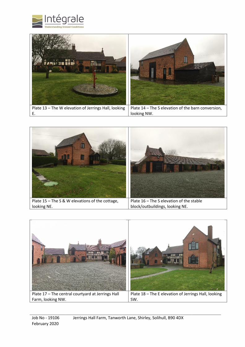
Clustered around a central courtyard slightly NW of site centre are:
Three-storey main building of traditional brick masonry and timber-framed construction with two-storey annex to S linked to a single-storey garden room (NW/W/SW). A two-storey barn conversion (S) and a detached two-storey cottage (SE). A single-storey stable block/outbuildings (N). The barn, cottage and outbuildings are of masonry construction. All buildings have pitched tiled roofs. The main building has a basement/cellar. Some sagging of the stable block roof was noted, otherwise no other obvious signs of structural distress were noted externally.
Surfacings & Condition An asphalt drive leads up to a courtyard of gravel hardstanding. Flagstones around building peripheries. Asphalt is in reasonable condition, some localised cracking.
Vegetation & Trees
Mature horse chestnut trees flank the main driveway. Copse of evergreen trees in SE corner of the site. Sporadic semi-mature and mature deciduous trees located around the site. Garden areas are turfed with lawn grass. Paddock areas comprise meadow grass, hydrophilic vegetation is present locally SE of site centre.
Water Courses Pond in the W of the site. No other surface water courses or drainage features noted within or adjacent to the site.
Site Boundary Features Wooden fencing in conjunction with screening hedgerows and sporadic trees. Locally, masonry wall opposite the site buildings on NNW boundary.
Potential Contamination Issues
None anticipated.
Potential Geotechnical Issues
Glacial Deposits can be poorly sorted and subsequently may vary in composition locally.
Other Features
The site is a Grade II Listed property. The consulting engineer advised that during a walkover of the property, seepages were noted rising from the floor slab and walls within the basement, which is typically drained by a pump.
Jerrings Hall Farm, Shirley, Solihull, 19106, February 2020 3
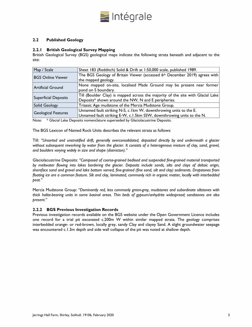
2.2 Published Geology 2.2.1 British Geological Survey Mapping British Geological Survey (BGS) geological maps indicate the following strata beneath and adjacent to the site: Map / Scale Sheet 183 (Redditch) Solid & Drift at 1:50,000 scale, published 1989.
BGS Online Viewer The BGS Geology of Britain Viewer (accessed 6th December 2019) agrees with the mapped geology.
Artificial Ground None mapped on-site, localised Made Ground may be present near former pond on S boundary.
Superficial Deposits Till (Boulder Clay) is mapped across the majority of the site with Glacial Lake Deposits* shown around the NW, N and E peripheries.
Solid Geology Triassic Age mudstone of the Mercia Mudstone Group.
Geological Features Unnamed fault striking N-S, c.1km W, downthrowing units to the E. Unnamed fault striking E-W, c.1.5km SSW, downthrowing units to the N.
Note: * Glacial Lake Deposits nomenclature superseded by Glaciolacustrine Deposits.
The BGS Lexicon of Named Rock Units describes the relevant strata as follows: Till: “Unsorted and unstratified drift, generally overconsolidated, deposited directly by and underneath a glacier without subsequent reworking by water from the glacier. It consists of a heterogenous mixture of clay, sand, gravel, and boulders varying widely in size and shape (diamicton).” Glaciolacustrine Deposits: “Composed of coarse-grained bedload and suspended fine-grained material transported by meltwater flowing into lakes bordering the glacier. Deposits include sands, silts and clays of deltaic origin, shoreface sand and gravel and lake bottom varved, fine-grained (fine sand, silt and clay) sediments. Dropstones from floating ice are a common feature. Silt and clay, laminated, commonly rich in organic matter, locally with interbedded peat.” Mercia Mudstone Group: “Dominantly red, less commonly green-grey, mudstones and subordinate siltstones with thick halite-bearing units in some basinal areas. Thin beds of gypsum/anhydrite widespread; sandstones are also present.” 2.2.2 BGS Previous Investigation Records Previous investigation records available on the BGS website under the Open Government Licence includes one record for a trial pit excavated c.200m W within similar mapped strata. The geology comprises interbedded orange- or red-brown, locally grey, sandy Clay and clayey Sand. A slight groundwater seepage was encountered c.1.3m depth and side wall collapse of the pit was noted at shallow depth.

Jerrings Hall Farm, Shirley, Solihull, 19106, February 2020 4
2.3 Outline History Historical maps accessed via freely available online resources indicate the following pertinent information:
Map Date Site Features / Land Use Adjacent Features (distance from site)
1886-88 Cluster of buildings around central courtyard slightly NW of site centre. Orchard in W of site. 2 No. ponds, one larger adjacent to W boundary, second smaller on SSE boundary. Apparent ditch connection from larger to smaller along SW and SE boundary. Further stream striking SW-NE across the E of the site to Tanworth Lane. Site boundary open to NNW and SSE. Track running from E boundary to central courtyard.
Tanworth Lane (Boundary ENE); open farmland (Boundary NNW/WSW/SSE); lakes/ponds (180m N/210m E/310m W/350m E); Stratford on Avon Canal (360m W). Surrounding farmland is divided by many drains, feeding to/from the various ponds.
1904-05 Orchard no longer present.
No significant changes. 1917 No significant changes.
1920-21 Pump to W of buildings.
1955 No significant changes. Line of pylons with overhead cable (15m S).
1968-70 Track now treelined. SSE boundary (field boundary or possible drain) present, cutting through S pond (mapped as ‘ponds’). Stream striking SW-NE across the site removed. N boundary (field boundary) adjacent to entrance track and rear of stable block. Apparent new building on E side of courtyard and another adjacent to site entrance (S of track). Small structure in SW of site adjacent to S pond.
Building/structure (150m E); residential properties on Lady Lane (160m SW).
1974-80 S pond not present. Site open to WSW and SSE, field/site boundaries removed.
High Leas Farm (20m E, closest building 50m E).
1992 No significant changes. No significant changes.
2.4 Radon Risk Information The UK Radon Atlas mapping (accessed via www.ukradon.org on 6th December 2019) indicates that the site lies within a 1km grid square in which all parts of the grid square are within the lowest band of radon potential and subsequently not within a Radon Affected Area. It may be prudent to obtain a site specific radon risk assessment to confirm the findings of the indicative mapping. Where it is concluded that no radon gas protection methods are needed, the Local Authority may have more conservative requirements and this aspect should be confirmed with their Building Control department.
Jerrings Hall Farm, Shirley, Solihull, 19106, February 2020 5
3.0 GROUND INVESTIGATION In view of the anticipated ground conditions, current site layout and proposed redevelopment, the following scope of investigation was completed. 3.1 Trial Pitting 3.1.1 Mechanical Trial Pitting 6 No. trial pits were mechanically excavated using a tracked mini excavator (1st Dig Plant Hire Limited) on 13th and 16th December 2019. The targeted trial pit locations, chosen by the consulting engineer and drainage engineer in liaison with Intégrale, are shown on Figure 1 and were referenced as SA1-5 and TP1. Two additional pits, SA2A and SA5A were selected whilst on-site after the original excavations were aborted after encountering land drains. The general procedures adopted during trial pitting, together with the detailed trial pit records are included in Appendix C. 3.1.2 Manual Trial Pitting 2 No. trial pits were manually excavated using hand tools on 16th December 2019. The trial pit locations, chosen by the consulting engineer to inspect the extent of the foundations of the existing stable block/outbuildings, are shown on Figure 1 and were referenced as FP1-2. Three further trial pits, referenced VP1 and VP3-4, were dug by hand solely for percolation testing. The general procedures adopted during trial pitting, together with the detailed trial pit records are included in Appendix C. 3.2 Infiltration Testing 3.2.1 BRE 365 (2007) – Conventional Soakaway Testing Soakaway tests were carried out in SA1, SA2A, SA3-4 and SA5A. Tests were proposed at both shallow depth (between c.0.5-1.0m BEGL) in SA3-4 and deeper (between c.1.0-1.5m BEGL) in SA1, SA2A and SA5A. The trial pits were filled from a bowser (provided by Liquiline Limited) and the drop in water level measured over time. The general procedures adopted during soakaway testing together with the soakaway records are included in Appendix D and discussed in Section 5. 3.2.2 Building Regulations Part H (2010) – Percolation Testing Further soakaway tests, VP1-2, for a proposed drainage field were also requested by the drainage engineer, with a further two positions VP3-4, selected whilst on-site. These 300x300x300mm pits were manually dug using hand tools then filled from containers and the drop in water level measured over time. VP1-2 were originally planned to be manually dug from the base of a mechanically excavated trial pit at c.0.7m BEGL, however mechanical excavation was aborted at VP2 after encountering a rapid groundwater seepage. The general procedures adopted during soakaway testing together with the soakaway records are included in Appendix E and discussed in Section 5. 3.2.3 Dual Ring Infiltrometer Testing Infiltration testing of topsoil was completed at 3 No. locations in line with the guidance given in BS EN12616. The infiltration test positions are shown on Figure 1 and were referenced as DR1-3. The infiltrometer records are included in Appendix F and discussed in Section 5. 3.3 Groundwater and Soils Gas Standpipe Installations and Monitoring Simple standpipes were installed in trial pits SA1, SA2A, SA3-4 and SA5A to between 0.5m and 1.0m depth and details are given on the trial pit logs. Monitoring has been undertaken on 1 No. occasion and the results are included in Appendix H, together with the general procedures adopted for installing standpipes. 3.4 Geotechnical Laboratory Testing A schedule of complementary soils testing was prepared by Intégrale and the physical tests were completed in accordance with BS 1377 (1990) by South West Geotechnical Limited and the chemical tests by i2 Analytical Limited. The results are provided in Appendix G with the testing strategy outlined as follows: Location Depth (m) Stratum Testing Criteria for test selection
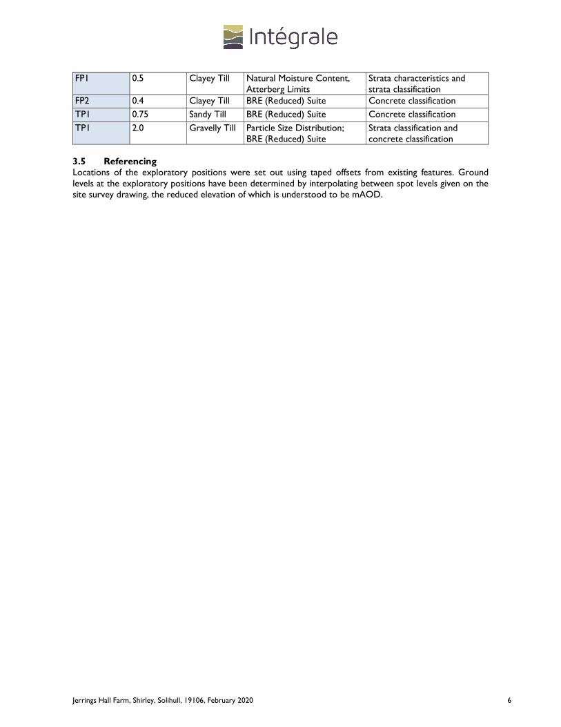
Jerrings Hall Farm, Shirley, Solihull, 19106, February 2020 6
FP1 0.5 Clayey Till Natural Moisture Content, Atterberg Limits
Strata characteristics and strata classification
FP2 0.4 Clayey Till BRE (Reduced) Suite Concrete classification
TP1 0.75 Sandy Till BRE (Reduced) Suite Concrete classification
TP1 2.0 Gravelly Till Particle Size Distribution; BRE (Reduced) Suite
Strata classification and concrete classification
3.5 Referencing Locations of the exploratory positions were set out using taped offsets from existing features. Ground levels at the exploratory positions have been determined by interpolating between spot levels given on the site survey drawing, the reduced elevation of which is understood to be mAOD.

Jerrings Hall Farm, Shirley, Solihull, 19106, February 2020 7
4.0 GROUND & GROUNDWATER CONDITIONS 4.1 Summary of Strata Encountered The strata encountered across the site have been divided into two zones which can be summarised as follows: A) Area of the Southern Proposed Modular Building (TP1) Depth (m) Description
GL to 0.2 Grass over TOPSOIL: (Comprising dark brown slightly sandy slightly gravelly clayey
Silt).
0.2 to 0.4 MADE GROUND: (Comprising moderately compact dark brown-grey gravelly very silty Sand).
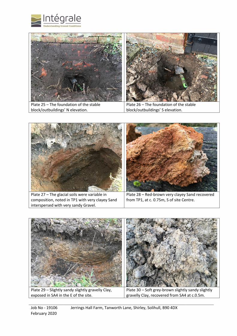
0.4 to 1.5 Loose to medium dense red-brown gravelly very clayey becoming clayey SAND, locally firm very sandy Clay. (TILL)
1.5 to 2.5 Medium dense red-brown silty sandy angular to subangular fine to coarse GRAVEL of quartzite. (TILL)
At shallow depth, the sandy Till showed signs of cohesive behaviour due to the high clayey fraction. B) Area of the Proposed Car Parking (SA3-4) Depth (m) Description
GL to 0.2 Grass over TOPSOIL: (Comprising dark brown slightly sandy clayey Silt).
0.2 to 0.7 Soft brown-grey slightly sandy silty CLAY.
(Possible GLACIOLACUSTRINE DEPOSITS or TILL)
0.7 to 1.1 Soft to firm orange-brown slightly sandy slightly gravelly silty CLAY. (TILL)
The glacial soils were locally variable and poorly sorted with interbeds of clayey sand. 4.2 Strata Properties 4.2.1 Made Ground / Topsoil Made Ground was proven in several of the exploratory positions and can be categorised as: Made Ground Type/Location
Topsoil Site wide
Made Ground Site centre & around building peripheries
Min./Max. thickness (m)
0.2/0.26 0.15/0.7
Main Constituents
Clay or Silt. Clayey Silt with quartzite, brick and metal fragments.
Properties Very soft or soft. Cohesive.
Soft or loosely to moderately compact.
Visual Contamination/ Odours
None noted. None noted.

Jerrings Hall Farm, Shirley, Solihull, 19106, February 2020 8
4.2.2 Glacial Deposits For the purposes of this report the uppermost horizons of the natural ground have been defined as Glaciolacustrine Deposits where they very soft or soft and grey-brown Clay in the east of the site and Till where they become soft to firm and red- or orange-brown Clay, Sand or Gravel. The properties can be summarised as: Stratum Glaciolacustrine Deposits –
Clay Till – Clay Till – Sand and Gravel
Min./Max. Thickness (m)
0.4/0.55 0.12/1.34 0.5/1.95
Soil Strength /Properties
Very soft or soft. Cohesive. Brown-grey.
Soft, soft to firm or firm. Cohesive. Orange- to red-brown or brown. Locally may include pockets of clayey Sand.
Loose to medium dense. Granular. Dominantly quartzite gravel. Red-brown, mottled grey. PSD: Gravel 62%, Sand 28%, Fines 11%. Silty/clayey very sandy GRAVEL.
Occurrence Extreme E only (SA3 & SA4), possibly localised in N.
Proven across the entire site.
Proven locally in the site centre & in N.
Sulphate/pH - SO4 0.071g/l pH 8.4
SO4 0.023g/l (sand), 0.014g/l (gravel) pH 5.5 (sand), 7.2 (gravel)
Visual Contamination/ Odours
None noted. None noted. None noted.
Note: PSD – Particle Size Distribution
The bedrock, Mercia Mudstone geology was not proven during the investigation. 4.3 Groundwater Groundwater was typically encountered at between 0.6m to 0.75m and 1.3m to 1.65m depth and typically rose by 20-30cm within 30 minutes. The following groundwater levels were encountered during the fieldworks on 13th December and the subsequent monitoring visit on 24th January 2020:
Exploratory Location 13/12/19 24/01/20
Depth below existing ground level (m) SA1 0.75 0.86 SA2A 1.35 0.7
SA3 0.85 0.1 SA4 0.75 0.6 SA5A 1.3 0.61 TP1 0.7 & 1.65 -

Jerrings Hall Farm, Shirley, Solihull, 19106, February 2020 9
4.4 Ground Gas The preliminary monitoring indicates that anomalous ground gases do not appear to be present. Summary results are detailed below with full information provided in Appendix H. Exploratory Location SA1 SA2A SA3 SA4 SA5A Response Zone (m) / Strata
1.2-1.5 / Till 1.2-1.5 / Till 0.7-1.0 / Till 0.7-1.0 / Till 1.2-1.5 / Till
Evidence of Contamination
None noted. None noted. None noted. None noted. None noted.
Monitoring Visits (No.) 1 1 1 1 1 Methane (%) 0.0 0.0 - 0.0 0.0 Carbon Dioxide (%) 0.0 0.1 - 0.0 0.0 Oxygen (%) 22.1 23.2 - 23.0 22.4 VOC (ppm) 0.0 0.0 - 0.0 0.0 Gas Flow (litres/hr) 0.1-0.2 0.1-0.2 - 0.1-0.2 0.1-0.2 Water levels (m) 0.86 0.7 0.1 0.6 0.61 Atmospheric Pressure Range (mb)
1004-1006 1004-1006 - 1004-1006 1004-1006
Jerrings Hall Farm, Shirley, Solihull, 19106, February 2020 10
5.0 GEOTECHNICAL CONSIDERATIONS 5.1 Scheme Details & Structural Loadings The proposed redevelopment is to include the lowering of the existing ground floor in the stable block/outbuildings, construction of a new modular teaching building centrally (between the existing barn and cottage buildings), a further modular teaching building adjacent to the existing outbuildings, remodelled access and new ‘grasscrete’ car parking in the eastern area. New soakaways are also proposed at specific locations. The new single storey modular building will be constructed at existing grade. The consulting engineer has advised that point loads will be in the region of 30kN per leg, and that based on a 600x600mm pad this requires an allowable bearing pressure of approximately 100kN/m2. Specific advice has not been requested on the lowering of the Stable Block floor. 5.2 Site Preparation and Earthworks Topsoil, typically c.200mm thick, and any localised areas of particularly poor quality Made Ground, should be removed from beneath proposed new building and hardstanding areas. Excavations to at least 2m depth are likely to be feasible with conventional soils excavating machinery. Pneumatic tools may be required to break out existing foundations or similar buried masonry obstructions. Much of the spoil resulting from excavations in the existing Made Ground may well be unsuitable for reuse as structural fill. At least 25-50% of other shallow depth excavation spoil should be suitable for reuse, providing it is handled with care. Some excavations to 1m depth may remain dry, but others may encounter slight or moderate infiltration/ perched groundwater seepage. Such excavations can be kept dry by intermittent pumping from a convenient sump. Temporary excavations in the existing Made Ground and variably weathered shallow depth soils will probably stand unsupported in the short term at gradients of about 1 on 2. Excavations below approximately 1m depth will require sheeting and shoring, particularly if personnel are to enter. Formations in the more clayey soils will be susceptible to deterioration due to site traffic and weather and should be protected immediately on exposure with 150mm of granular material, or 75mm of lean mix concrete. Any desiccated (or root invaded) clayey soils should be excavated and made good with well compacted granular material. 5.3 Foundations and Ground Floor Slabs 5.3.1 Typical Ground Conditions The investigation has proven a discontinuous veneer of Topsoil/Hardstanding over localised thin (<0.5m) existing Made Ground. The Glacial Soils beneath are variable in composition but generally clayey, locally sandy. The clayey soils are soft, soft to firm or firm. The granular Glacial Soils are initially loose, rapidly becoming medium dense. The Mercia Mudstone bedrock was not proven during this investigation. The groundwater table appears to be at c.0.8-1.0m depth but the Glacial Soils can provide an adequate bearing stratum for shallow footings.
Jerrings Hall Farm, Shirley, Solihull, 19106, February 2020 11
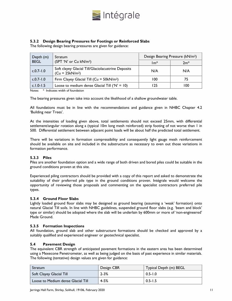
5.3.2 Design Bearing Pressures for Footings or Reinforced Slabs The following design bearing pressures are given for guidance:
Depth (m) BEGL
Stratum (SPT ‘N’ or Cu kN/m2)
Design Bearing Pressure (kN/m2)
1m* 2m*
c.0.7-1.0 Soft clayey Glacial Till/Glaciolacustrine Deposits (Cu = 25kN/m2)
N/A N/A
c.0.7-1.0 Firm Clayey Glacial Till (Cu = 50kN/m2) 100 75
c.1.0-1.5 Loose to medium dense Glacial Till (‘N’ = 10) 125 100 Notes: * Indicates width of foundation
The bearing pressures given take into account the likelihood of a shallow groundwater table. All foundations must be in line with the recommendations and guidance given in NHBC Chapter 4.2 ‘Building near Trees’. At the intensities of loading given above, total settlements should not exceed 25mm, with differential settlement/angular rotation along a (typical 10m long mesh reinforced) strip footing of not worse than 1 in 500. Differential settlement between adjacent point loads will be about half the predicted total settlement. There will be variations in formation compressibility and consequently light gauge mesh reinforcement should be available on site and included in the substructure as necessary to even out those variations in formation performance. 5.3.3 Piles Piles are another foundation option and a wide range of both driven and bored piles could be suitable in the ground conditions proven at this site. Experienced piling contractors should be provided with a copy of this report and asked to demonstrate the suitability of their preferred pile type in the ground conditions proven. Intégrale would welcome the opportunity of reviewing those proposals and commenting on the specialist contractors preferred pile types. 5.3.4 Ground Floor Slabs Lightly loaded ground floor slabs may be designed as ground bearing (assuming a ‘weak’ formation) onto natural Glacial Till soils. In line with NHBC guidelines, suspended ground floor slabs (e.g. ‘beam and block’ type or similar) should be adopted where the slab will be underlain by 600mm or more of ‘non-engineered’ Made Ground. 5.3.5 Formation Inspections All foundation, ground slab and other substructure formations should be checked and approved by a suitably qualified and experienced engineer or geotechnical specialist. 5.4 Pavement Design The equivalent CBR strength of anticipated pavement formations in the eastern area has been determined using a Mexecone Penetrometer, as well as being judged on the basis of past experience in similar materials. The following (tentative) design values are given for guidance:
Stratum Design CBR Typical Depth (m) BEGL
Soft Clayey Glacial Till 2-3% 0.5-1.0
Loose to Medium dense Glacial Till 4-5% 0.5-1.5

Jerrings Hall Farm, Shirley, Solihull, 19106, February 2020 12
It would be prudent to allow a contingency for treating ‘soft-spots’ equivalent to 25% of the proposed hardstanding area to a depth of typically 500mm. All soft spots should be excavated and replaced with suitable well compacted granular material. Where there could be rapid variations in formation strength, consideration should be given to a sandwiched geogrid construction which will help even out those variations to within acceptable limits. Intégrale can give further guidance on request. 5.5 Protection of Buried Concrete In line with BRE Special Digest 1:2005 ‘Concrete in Aggressive Ground’, 3 No. samples of Glacial Till were tested for water soluble sulphate, total acid soluble sulphate, total sulphur and pH. The results are reported in Appendix G. The desk study and ground investigation indicate the site can be categorised as being:
• Brownfield location including aggressive materials or leachates, but without pyrites;
• Mobile groundwater conditions, as water will flow into excavations or is percolating slowly through the ground.
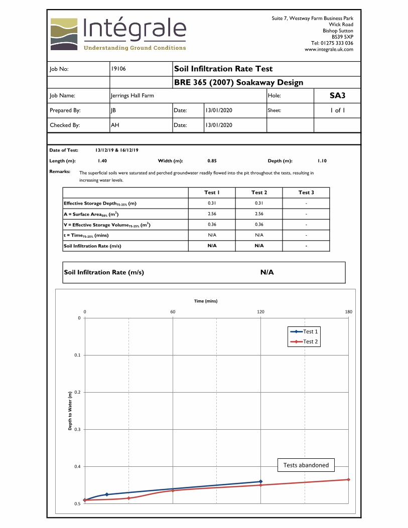
The results show a range of water soluble sulphate of 13.8-71.0mg/l. The lowest pH value was 5.5. The results for total acid soluble sulphate (0.05% to 0.026%) and total sulphur (0.008% to 0.071%) indicate pyrite which may oxidise is not present. It is therefore recommended that a Design Sulphate Class of DS-1 and an ACEC Class of AC-1 be adopted for budgeting purposes. 5.6 Drainage Considerations The engineer requested soakaway trials in 5 No. investigation locations, with supplementary percolation and infiltration testing in additional locations determined on site. A water bowser and pump were used to fill trial pits SA3 and SA4 between c0.5m and c1.0m depth, and SA1, SA2A and SA5A between c.1.0m and c.1.5m depth. The drop in water level was recorded over time and the results are included in Appendix D. During excavation, all positions encountered perched slight to moderate groundwater seepages which ultimately led to water levels rising throughout testing in each of the positions; subsequently an extrapolated infiltration rate could not be calculated. Percolation testing was undertaken in small 300x300x300mm manually excavated pits which were filled by hand from containers. The drop in water level was recorded over time with the results provided in Appendix E. Three extrapolated tests were only completed in one of the three locations, VP3, in the northern paddock area with an average extrapolated VP value of 40.93secs/mm calculated. In the same timeframe a single test was completed in VP4, c. 10m east, which recorded an extrapolated VP value of 178.45secs/mm. Percolation was similarly inhibited in VP1, in the southern paddock, where testing was completed across two days for an average extrapolate VP value of 143.60secs/mm. Infiltration testing within the clayey topsoil was undertaken in 3 No. locations following stripping of the overlying grass and root invaded soils. The dual rings were filled by hand from a container and the drop in water level was recorded over time with the results provided in Appendix F. Within approximately 30-40 minutes the water level had only dropped by 5-18mm, suggesting an infiltration rate between 2.78x10⁻⁶m/s and 7.50x10⁻⁶m/s, although three tests could not be completed at each position. No discernible drop in water level was noted at DR1 and subsequently was deemed to be practically impermeable. Very shallow perched water ingress was noted at DR2 when the topsoil had been stripped back to 0.05m depth. It is considered that given the depth to standing groundwater (0.7-1.5m), and predominantly clayey nature of natural soils, soakaways are unlikely to be successful at this site. Once the design layout is ‘frozen’, supplementary trials (at specific locations and appropriate depths) should be completed to confirm the above (and Intégrale can give further assistance with this aspect if required).

Jerrings Hall Farm, Shirley, Solihull, 19106, February 2020 13
5.7 Contamination Considerations Significant Made Ground has not been encountered, nor have any signs of visual or olfactory contamination. The pH value of the glacial soils exceeded the WRAS threshold and therefore all new buried water pipes and infrastructure should be protective against chemical attack. The single gas monitoring visit has proven trace carbon dioxide and no methane or VOCs. This suggests a normal gas regime. Although to conform strictly to CIRIA C665, further monitoring visits would be required, the ground gas readings to date and the absence of a known source (albeit no desk study has been completed) are likely to be sufficient evidence to support the above conclusions. As detailed in Section 2, no radon precautions are likely to be necessary. Should soils need removal to a suitably licensed tip, then waste characterisation and classification in accordance with the Environment Agency’s current technical guidance will need to be undertaken. In view of the ground conditions and analytical results to date, it seems unlikely that it will be necessary to undertake further contaminated land investigation, however the project team should consider whether there is, or is likely to be a planning condition or other aspects which require detailed contamination assessment for this project.

SA3
SA4SA1
TP1
FP2
FP1
VP1
VP2
SA2A
SA5A
VP3VP4
DR3
DR1
DR2
Figure 1Site Plan
Jerrings Hall Farm
Solihull
Tanworth Lane
B90 4DX
Shirley
Scale = 1:250 (approx.) @ A3
Job No: 19106February 2020
Site investigation boundary
Key:
BRE365 Soakaway
Foundation Inspection Pit
Trial Pit
Building Regs Part H Soakaway
Dual Ring Infiltrometer
Proposed development
GEOLOGICAL • GEOTECHNICAL • ENVIRONMENTAL • ENGINEERING
Integrale Limited, Suite 7, Westway Farm Business Park, Wick Road, Bishop Sutton, Somerset, BS39 5XP United Kingdom Tel: 01275 333 036 www.integrale.uk.com
Registered Office: The Granary, Chewton Fields, Ston Easton, Somerset, BA3 4BX United Kingdom VAT Reg. No. 609 7402 37
Appendix A
Site Location

Suite 7, Westway Farm Business Park Wick Road, Bishop Sutton, Somerset, BS39 5XP, United Kingdom Tel: 01275 333036 www.integrale.uk.com
GEOLOGICAL • GEOTECHNICAL • ENVIRONMENTAL • ENGINEERING
Intégrale is a trading name of Integrale Limited. Registered Office: The Granary, Chewton Fields, Ston Easton, Somerset, BA3 4BX United Kingdom Company Registration No. 2855366 England VAT Reg. No. 609 7402 37
Project: Jerrings Hall Farm, Tanworth Lane, Shirley, Solihull, B90 4DX Job No. 19106
Site Location Plan
North
Site
GEOLOGICAL • GEOTECHNICAL • ENVIRONMENTAL • ENGINEERING
Integrale Limited, Suite 7, Westway Farm Business Park, Wick Road, Bishop Sutton, Somerset, BS39 5XP United Kingdom Tel: 01275 333 036 www.integrale.uk.com
Registered Office: The Granary, Chewton Fields, Ston Easton, Somerset, BA3 4BX United Kingdom VAT Reg. No. 609 7402 37
Appendix B
Site Description & Photographs

Suite 7, Westway Farm Business Park Wick Road, Bishop Sutton, Somerset, BS39 5XP, United Kingdom Tel: 01275 333036 www.integrale.uk.com
GEOLOGICAL • GEOTECHNICAL • ENVIRONMENTAL • ENGINEERING
Intégrale is a trading name of Integrale Limited. Registered Office: The Granary, Chewton Fields, Ston Easton, Somerset, BA3 4BX United Kingdom Company Registration No. 2855366 England VAT Reg. No. 609 7402 37
REFERENCES
Project No. 19106
Site Address Jerrings Hall Farm, Tanworth Lane, Shirley, Solihull, B90 4DX
Grid Reference E421111 N276302
Date of Visit 13/12/19
Names of individuals met with on site Penny Gibson (Residential Property Manager - Savills)
Prepared by JB
SITE – GENERAL
Plan of site See Figure 1.
Site size (area): Soft landscaping 80%; buildings 10%; Hardstanding <10%; pond (>5%).
Current use: Residential (currently unoccupied).
Site Area: c.1.65 Hectares; roughly rectangular.
Maximum Dimensions: c.150m ENE-WSW by c.110m NNW-SSE.
Boundaries: Boundary NNW: Mixture of wooden fencing and hedgerow, locally with masonry wall adjacent to the site buildings and sporadic trees.
Boundary ENE: Wooden fencing and hedgerows with occasional trees.
Boundary SSE: Wooden fencing with sporadic trees.
Boundary WSW: Wooden fencing, locally with hedgerows adjacent to the pond and the garden in the NW.
Any access limitations: None anticipated, other than access codes.
Any specific working hours/access requirements
08:00-17:00. Gate access code supplied by Savills.
Any specific H&S hazards/considerations: No specific considerations.
Water, power supply/hydrant on site: Water and power supply is currently disconnected at the property. No hydrants noted within the site or along the adjacent carriageway of Tanworth Lane.
SITE – BUILDINGS
Age of building(s) c.16th or 17th Century.
Building appearance: Clustered around a central courtyard slightly NW of site centre are:
Three-storey main building of traditional brick masonry and timber-framed construction with two-storey annex to S linked to a single-storey ‘garden room’ (NW/W/SW). A two-storey barn conversion (S) and a detached two-storey cottage (SE). A single-storey stable block/outbuildings (N). The barn, cottage and outbuildings are of masonry construction. All buildings have pitched tiled roofs. The main building has a basement/cellar.
State of buildings: Some sagging of stable block/outbuildings roof. No other obvious signs of structural distress noted externally.
Tanks: Unknown, no access to buildings.
Heating: Unknown, no access to buildings.
Chemical storage: Unknown, no access to buildings.
Gas control measures: Some venting locally.
Other evidence of industrial activity: N/A
Asbestos/deleterious materials: None noted.
Electrical equipment/transformers: N/A
GEOLOGICAL • GEOTECHNICAL • ENVIRONMENTAL • ENGINEERING
Integrale Limited, Suite 7, Westway Farm Business Park, Wick Road, Bishop Sutton, Somerset, BS39 5XP United Kingdom
Tel: 01275 333 036 www.integrale.uk.com
Registered Office: The Granary, Chewton Fields, Ston Easton, Somerset, BA3 4BX United Kingdom VAT Reg. No. 609 7402 37
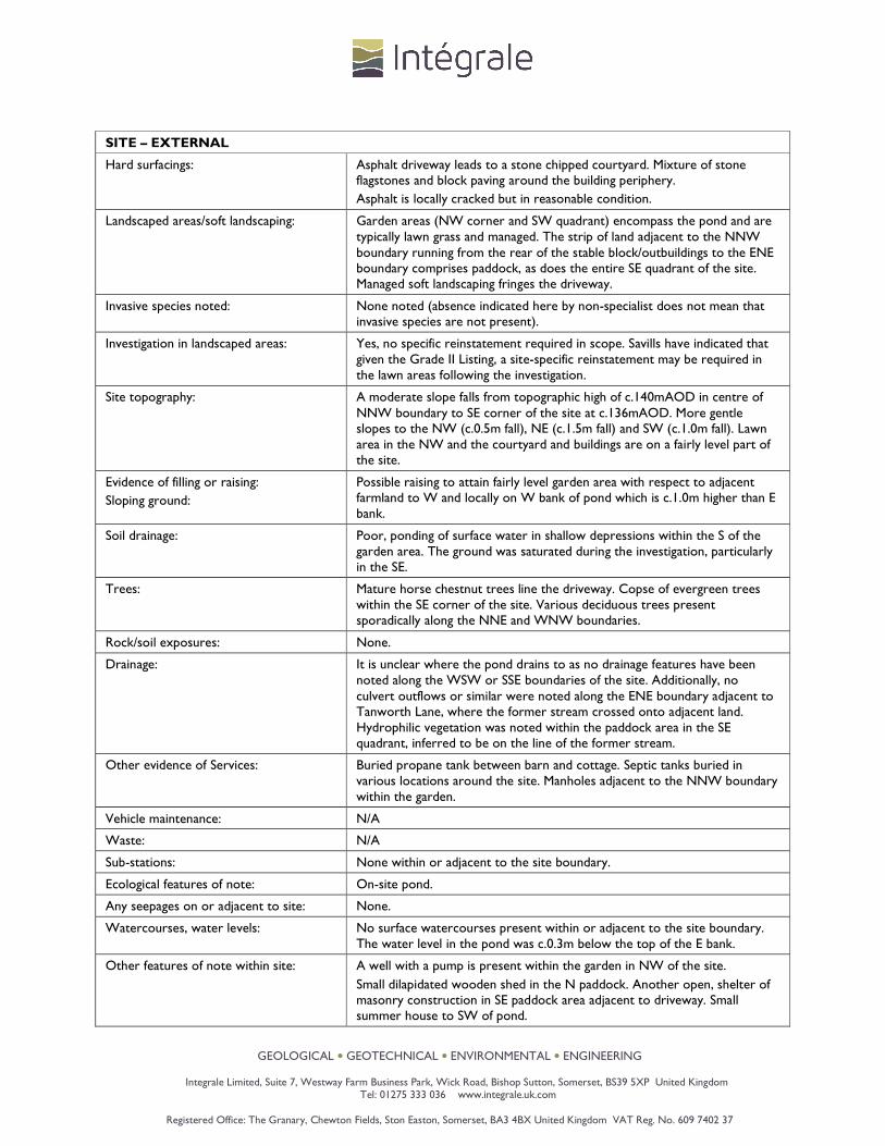
SITE – EXTERNAL
Hard surfacings: Asphalt driveway leads to a stone chipped courtyard. Mixture of stone flagstones and block paving around the building periphery.
Asphalt is locally cracked but in reasonable condition.
Landscaped areas/soft landscaping: Garden areas (NW corner and SW quadrant) encompass the pond and are typically lawn grass and managed. The strip of land adjacent to the NNW boundary running from the rear of the stable block/outbuildings to the ENE boundary comprises paddock, as does the entire SE quadrant of the site. Managed soft landscaping fringes the driveway.
Invasive species noted: None noted (absence indicated here by non-specialist does not mean that invasive species are not present).
Investigation in landscaped areas: Yes, no specific reinstatement required in scope. Savills have indicated that given the Grade II Listing, a site-specific reinstatement may be required in the lawn areas following the investigation.
Site topography: A moderate slope falls from topographic high of c.140mAOD in centre of NNW boundary to SE corner of the site at c.136mAOD. More gentle slopes to the NW (c.0.5m fall), NE (c.1.5m fall) and SW (c.1.0m fall). Lawn area in the NW and the courtyard and buildings are on a fairly level part of the site.
Evidence of filling or raising:
Sloping ground:
Possible raising to attain fairly level garden area with respect to adjacent farmland to W and locally on W bank of pond which is c.1.0m higher than E bank.
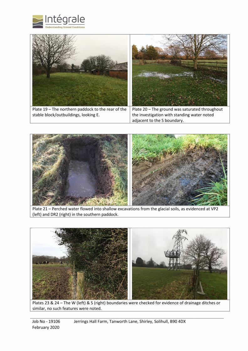
Soil drainage: Poor, ponding of surface water in shallow depressions within the S of the garden area. The ground was saturated during the investigation, particularly in the SE.
Trees: Mature horse chestnut trees line the driveway. Copse of evergreen trees within the SE corner of the site. Various deciduous trees present sporadically along the NNE and WNW boundaries.
Rock/soil exposures: None.
Drainage: It is unclear where the pond drains to as no drainage features have been noted along the WSW or SSE boundaries of the site. Additionally, no culvert outflows or similar were noted along the ENE boundary adjacent to Tanworth Lane, where the former stream crossed onto adjacent land. Hydrophilic vegetation was noted within the paddock area in the SE quadrant, inferred to be on the line of the former stream.
Other evidence of Services: Buried propane tank between barn and cottage. Septic tanks buried in various locations around the site. Manholes adjacent to the NNW boundary within the garden.
Vehicle maintenance: N/A
Waste: N/A
Sub-stations: None within or adjacent to the site boundary.
Ecological features of note: On-site pond.
Any seepages on or adjacent to site: None.
Watercourses, water levels: No surface watercourses present within or adjacent to the site boundary. The water level in the pond was c.0.3m below the top of the E bank.
Other features of note within site: A well with a pump is present within the garden in NW of the site.
Small dilapidated wooden shed in the N paddock. Another open, shelter of masonry construction in SE paddock area adjacent to driveway. Small summer house to SW of pond.

GEOLOGICAL • GEOTECHNICAL • ENVIRONMENTAL • ENGINEERING
Integrale Limited, Suite 7, Westway Farm Business Park, Wick Road, Bishop Sutton, Somerset, BS39 5XP United Kingdom
Tel: 01275 333 036 www.integrale.uk.com
Registered Office: The Granary, Chewton Fields, Ston Easton, Somerset, BA3 4BX United Kingdom VAT Reg. No. 609 7402 37
SURROUNDING LAND USES
General site context: Agricultural.
Land use – north-northwest: Rough pasture with cows grazing.
Land use – east-northeast: Pavement and carriageway of Tanworth Lane.
Land use – south-southeast: Arable farmland.
Land use – west-southwest: Arable farmland.
Nearby (<500m) sources of pollution: Adjacent farming land uses (fertilisers, pesticides etc.).
Electricity pylon with subsurface cables c.10m S.
Nearby river/surface water features: None within 100m of the site boundary. Numerous ponds at greater distance from the site.
Local ground profiles and signs of instability. No signs of instability noted locally. Surrounding land is gently sloping to moderately sloping in all directions from the site boundaries.
Evidence of structural distress on nearby buildings.
None noted.
Evidence of mining history: N/A
Nearby rock/soil outcrops. None.
Vegetation: Hedgerows and a mixture of trees follow field boundaries and road verges.
Adjacent geotechnical features of note: None.
Other features of note adjacent to site: None.

Job No - 19106 Jerrings Hall Farm, Tanworth Lane, Shirley, Solihull, B90 4DX
February 2020
018
Plate 1 – The site entrance, looking E. Plate 2 – The northern paddock, looking NW.
Plate 3 – The southern paddock, looking S. Plate 4 – The southern paddock, looking SW.
Plate 5 – Looking W towards the farm buildings from the southern paddock.
Plate 6 – Hydrophilic vegetation locally within the W of the southern paddock, looking SW towards former pond location.
Job No - 19106 Jerrings Hall Farm, Tanworth Lane, Shirley, Solihull, B90 4DX
February 2020
018
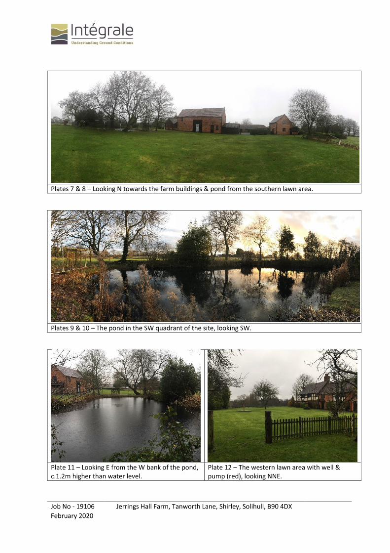
Plates 7 & 8 – Looking N towards the farm buildings & pond from the southern lawn area.
Plates 9 & 10 – The pond in the SW quadrant of the site, looking SW.
Plate 11 – Looking E from the W bank of the pond, c.1.2m higher than water level.
Plate 12 – The western lawn area with well & pump (red), looking NNE.
Job No - 19106 Jerrings Hall Farm, Tanworth Lane, Shirley, Solihull, B90 4DX
February 2020
018
Plate 13 – The W elevation of Jerrings Hall, looking E.
Plate 14 – The S elevation of the barn conversion, looking NW.
Plate 15 – The S & W elevations of the cottage, looking NE.
Plate 16 – The S elevation of the stable block/outbuildings, looking NE.
Plate 17 – The central courtyard at Jerrings Hall Farm, looking NW.
Plate 18 – The E elevation of Jerrings Hall, looking SW.
Job No - 19106 Jerrings Hall Farm, Tanworth Lane, Shirley, Solihull, B90 4DX
February 2020
018
Plate 19 – The northern paddock to the rear of the stable block/outbuildings, looking E.
Plate 20 – The ground was saturated throughout the investigation with standing water noted adjacent to the S boundary.
Plate 21 – Perched water flowed into shallow excavations from the glacial soils, as evidenced at VP2 (left) and DR2 (right) in the southern paddock.
Plates 23 & 24 – The W (left) & S (right) boundaries were checked for evidence of drainage ditches or similar, no such features were noted.
Job No - 19106 Jerrings Hall Farm, Tanworth Lane, Shirley, Solihull, B90 4DX
February 2020
018
Plate 25 – The foundation of the stable block/outbuildings’ N elevation.
Plate 26 – The foundation of the stable block/outbuildings’ S elevation.
Plate 27 – The glacial soils were variable in composition, noted in TP1 with very clayey Sand interspersed with very sandy Gravel.
Plate 28 – Red-brown very clayey Sand recovered from TP1, at c. 0.75m, S of site Centre.
Plate 29 – Slightly sandy slightly gravelly Clay, exposed in SA4 in the E of the site.
Plate 30 – Soft grey-brown slightly sandy slightly gravelly Clay, recovered from SA4 at c.0.5m.

GEOLOGICAL • GEOTECHNICAL • ENVIRONMENTAL • ENGINEERING
Integrale Limited, Suite 7, Westway Farm Business Park, Wick Road, Bishop Sutton, Somerset, BS39 5XP United Kingdom Tel: 01275 333 036 www.integrale.uk.com
Registered Office: The Granary, Chewton Fields, Ston Easton, Somerset, BA3 4BX United Kingdom VAT Reg. No. 609 7402 37
Appendix C
Trial Pit Logs & Sketches

Suite 7, Westway Farm Business Park Wick Road, Bishop Sutton, Somerset, BS39 5XP, United Kingdom Tel: 01275 333036 www.integrale.uk.com
GEOLOGICAL • GEOTECHNICAL • ENVIRONMENTAL • ENGINEERING
Intégrale is a trading name of Integrale Limited. Registered Office: The Granary, Chewton Fields, Ston Easton, Somerset, BA3 4BX United Kingdom Company Registration No. 2855366 England VAT Reg. No. 609 7402 37
STANDARD METHODOLOGY FOR MECHANICAL TRIAL PITTING
Trial pits are mechanically excavated using a wheeled or tracked backhoe or mini-excavator, typically fitted with toothed buckets. The trial pit locations are selected using information on the proposed redevelopment, existing buried services and structures, ongoing site use, reinstatement requirements and time constraints. Those positions are shown on Figure 1 and the trial pit records included as a separate appendix. Trial pitting was directed and supervised full-time by an experienced engineering geologist who carried out insitu testing, kept a record of the strata encountered, noted the pit side stability and ease of digging, any water ingresses, took photographs and recovered representative disturbed samples. Insitu testing comprised hand shear vane measurement in appropriate cohesive strata to provide a direct reading of insitu undrained shear strength. Tests were completed from within the pit to depths of approximately 1.2m below ground level and within excavated spoil below this. The hand shear vane is inserted into cohesive soil and rotated at an even speed equivalent to one rotation per 60 seconds. Three tests are typically taken and the average result used as the undrained shear strength in kN/m2. Mexicone penetrometer testing was undertaken either from ground level or at shallow depth within trial pits and the test results are included in the trial pit records. The mexicone penetrometer is a simple, hand-held device which gives a direct read out of equivalent CBR strength, on a cylindrical gauge. Readings are recorded for each 75mm penetration and where suitable soils are present, successive readings up to 0.6m total penetration can be achieved. However, the test can abort on coarse granular soils or other obstructions and in this case the term ‘refusal’ is given in the test records. On completion the pits were backfilled with their spoil, compacted with the excavator bucket and the surplus left mounded to allow for subsequent consolidation settlement. If specific reinstatement has been requested by the client, this is confirmed in the main text of this report. The trial pit records have been prepared using Gint software, taking into account both site descriptions and subsequent laboratory testing.

Suite 7, Westway Farm Business Park Wick Road, Bishop Sutton, Somerset, BS39 5XP, United Kingdom Tel: 01275 333036 www.integrale.uk.com
GEOLOGICAL • GEOTECHNICAL • ENVIRONMENTAL • ENGINEERING
Intégrale is a trading name of Integrale Limited. Registered Office: The Granary, Chewton Fields, Ston Easton, Somerset, BA3 4BX United Kingdom Company Registration No. 2855366 England VAT Reg. No. 609 7402 37
STANDARD METHODOLOGY FOR HAND EXCAVATED TRIAL PITS
Trial pits are manually excavated using hand tools with assistance from a mechanical excavator where possible. The trial pit locations are selected using information on the proposed redevelopment, existing buried services and structures, ongoing site use, reinstatement requirements and time constraints. Those positions are shown on Figure 1 and the trial pit records included as a separate appendix. Where necessary, details of exposed foundations are annotated on a measured sketch section appended to the trial pit records. Trial pitting was directed and supervised full-time by an experienced engineering geologist who carried out testing, kept a record of the strata encountered, noted the pit side stability and ease of digging, any water ingresses, took photographs and recovered representative disturbed samples. Testing comprised hand shear vane measurement in appropriate cohesive strata to provide a direct reading of insitu undrained shear strength. Tests were completed on recovered samples from the pit to depths of up to approximately 1.0m below ground level. The hand shear vane is inserted into cohesive soil and rotated at an even speed equivalent to one rotation per 60 seconds. Three tests are typically taken and the average result used as the undrained shear strength in kN/m2. If the material is suitable, the soil strength is examined using a pocket penetrometer. Mexicone penetrometer testing was undertaken either from ground level or at shallow depth within trial pits and the test results are included in the trial pit records. The mexicone penetrometer is a simple, hand-held device which gives a direct read out of equivalent CBR strength, on a cylindrical gauge. Readings are recorded for each 75mm penetration and where suitable soils are present, successive readings up to 0.6m total penetration can be achieved. However, the test can abort on coarse granular soils or other obstructions and in this case the term ‘refusal’ is given in the test records. On completion the pits were backfilled with their spoil, compacted by hand and the surplus left mounded to allow for subsequent consolidation settlement. If specific reinstatement has been requested by the client, this is confirmed in the main text of this report. The trial pit records have been prepared using Gint software, taking into account both site descriptions and subsequent laboratory testing.
Water Strike
Water Level (after 20 minutes)
AMALBBLKCCBRDESEWG
J
LBMSPTLSTWUUTW
HVPHSVMEXPID
Amalgamated sampleBulk disturbed sample
Block sample
Core sampleCBR mould sample
Small disturbed sampleEnvironmental sampleEnvironmental water sample
Gas sample
Jar sampleLarge bulk disturbed sampleMazier type sample
Standard penetration sampleThin-walled push in sample
Undisturbed sample - open driveThin wall open drive tube samplerWater sample
Hand-held shear vane testHand-held shear vane testMexicone penetrometer testPhotoionization detector (gas)
Note: composite soil types will besignified by combined soil types e.g.
SAMPLES AND TESTS
INSTALLATIONS
Ups
tand
ing c
over
Concrete
Bentonite
Sand Filter
Gravel Filter
Arisings
Grout
Flush
cov
er
Slotted
Pipe
Plain P
ipe
Slotted
Pipe
Plain P
ipeWATER SYMBOLS
Suite 7, Westway Farm Business ParkWick RoadBishop SuttonBS39 5XPTel: 01275 333 036www.integrale.uk.com
Intégrale is a trading name of Integrale Limited Registered Office: The Granary, Chewton Fields, Ston Easton, Somerset, BA3 4BX, United Kingdom Company Registration No. 2855366 England VAT Reg. No. 609 7402 37
GEOLOGICAL l GEOTECHNICAL l ENVIRONMENTAL l ENGINEERING
Coarse Grained Metamorphic
Medium Grained Metamorphic
Fine Grained Metamorphic
Medium Grained Igneous
Fine Grained Igneous
Coarse Grained IgneousChalk
Limestone
Conglomerate
Breccia
Sandstone
Siltstone
Mudstone
Shale
Coal
Pyroclastic (Volcanic Ash)
Gypsum, Rocksalt, etc.
Topsoil
Concrete
Made Ground (Fill)
Peat
Clay
Silt
Sand
Gravel
Cobbles
Boulders
Silty SandVoid/Broken Ground
SOILS SEDIMENTARY IGNEOUS
METAMORPHIC
EXPLORATORY HOLE EXPLANATION SHEET
Trial Pit LogTrialpit No
TP1Sheet 1 of 1
Project Name: Jerrings Hall Farm
Project No.19106
Co-ords:Level:
-138.75
Date16/12/2019
Location:
Client:
Tanworth Lane, Shirley, Solihull, B90 4DX
Sanderson Weatherall LLP
Dimensions (m):
Depth2.35
0.6
1.8 Scale1:15
LoggedJB
Remarks:
Stability:
Slight groundwater seepage c.0.7m. Rapid groundwater seepage c.1.65m.
Spalling in Superficial Deposits below c.0.4m.
Wat
erSt
rike Samples and In Situ Testing
Depth Type ResultsDepth
(m)
0.20
0.40
1.65
2.35
Level(m)
138.55
138.35
137.10
136.40
Legend Stratum Description
Lawn grass over TOPSOIL: (Comprising dark brown slightly sandy slightly gravelly clayey Silt with fine fibrous roots throughout. Gravel is angular to subangular fine to medium quartzite.)
c.0.2m: Plastic sheeting at base of stratum.MADE GROUND: (Comprising moderately compact dark brown-grey gravelly very silty fine to medium Sand. Gravel is angular to subangular fine to medium quartzite, charcoal and rare timber and metal fragments.)Loose to medium dense red-brown mottled grey slightly gravelly clayey fine to coarse typically fine to medium SAND with courses of clayey sandy Gravel. Gravel is angular to subrounded fine quartzite.(TILL)
From c.0.4m to 0.7m: Very clayey.
Mexecone at 0.7m: Refusal.
Medium dense red-brown silty sandy angular to subangular fine to coarse GRAVEL of quartzite with low cobble content. Cobbles are subangular to subrounded quartzite. (TILL)
End of pit at 2.35 m
1
2
3
0.10 ES
0.30 ES
0.50 D
0.75 D
1.00 D
1.50 D
2.00 B
Trial Pit LogTrialpit No
SA1Sheet 1 of 1
Project Name: Jerrings Hall Farm
Project No.19106
Co-ords:Level:
-139.33
Date13/12/2019
Location:
Client:
Tanworth Lane, Shirley, Solihull, B90 4DX
Sanderson Weatherall LLP
Dimensions (m):
Depth1.60
0.6
1 Scale1:10
LoggedJB
Remarks:
Stability:
Slight groundwater seepage at c.0.75m.
Spalling within Superficial Deposits below 0.3m.
Wat
erSt
rike Samples and In Situ Testing
Depth Type ResultsDepth
(m)
0.26
0.65
1.60
Level(m)
139.07
138.68
137.73
Legend Stratum Description
Grass over TOPSOIL: (Comprising soft dark brown slightly sandy clayey Silt with abundant fine fibrous roots to 0.05m and little extraneous material comprising brick fragments.)
Very soft brown-grey slightly sandy slightly gravelly silty CLAY. Gravel is subangular to rounded fine to coarse of chert and quartzite.(TILL)
Soft to firm orange-brown mottled grey slightly gravelly sandy CLAY locally loose gravelly very clayey fine to medium sand. Gravel is angular to rounded fine to coarse quartzite.(TILL)
End of pit at 1.60 m
1
2

Trial Pit LogTrialpit No
SA2ASheet 1 of 1
Project Name: Jerrings Hall Farm
Project No.19106
Co-ords:Level:
-138.40
Date13/12/2019
Location:
Client:
Tanworth Lane, Shirley, Solihull, B90 4DX
Sanderson Weatherall LLP
Dimensions (m):
Depth1.50
0.6
1.5 Scale1:10
LoggedJB
Remarks:
Stability:
Slight groundwater seepage c.1.35m.Moved c.2.0m NE after SA2 encountered a land drain at c.0.6mBGL.
Spalling in Superficial Deposits below c.0.9m.
Wat
erSt
rike Samples and In Situ Testing
Depth Type ResultsDepth
(m)
0.70
1.25
1.50
Level(m)
137.70
137.15
136.90
Legend Stratum Description
Grass over MADE GROUND: (Comprising soft dark brown slightly sandy slightly gravelly clayey Silt with low cobble content and abundant fine fibrous roots to 0.3m. Gravel is angular to rounded fine to coarse quartzite, brick and metal fragments. Cobbles are whole and fragments of brick.)
Firm brown very sandy CLAY with rare angular to subangular fine gravel of quartzite. (TILL)
Firm orange-brown very sandy CLAY with rare angular to subangular fine gravel of quartzite. (TILL)
End of pit at 1.50 m
1
2

Trial Pit LogTrialpit No
SA3Sheet 1 of 1
Project Name: Jerrings Hall Farm
Project No.19106
Co-ords:Level:
-137.75
Date13/12/2019
Location:
Client:
Tanworth Lane, Shirley, Solihull, B90 4DX
Sanderson Weatherall LLP
Dimensions (m):
Depth1.10
0.85
1.4 Scale1:10
LoggedJB
Remarks:
Stability:
Moderate groundwater seepage c.0.85m.
Spalling from both long edges below 0.5m. Pit collapsed back to c.0.95m. Re-excavated and battered back slightly.
Wat
erSt
rike Samples and In Situ Testing
Depth Type ResultsDepth
(m)
0.25
0.80
1.10
Level(m)
137.50
136.95
136.65
Legend Stratum Description
Grass over TOPSOIL: (Comprising dark brown slightly sandy clayey Silt with fine fibrous roots to c.0.1m.)
Soft brown-grey slightly sandy silty CLAY.(POSSIBLE GLACIOLACUSTRINE DEPOSITS/TILL)
Soft to firm orange-brown slightly sandy slightly gravelly silty CLAY. Gravel is angular to subrounded fine to medium quartzite.(TILL)
End of pit at 1.10 m
1
2
Trial Pit LogTrialpit No
SA4Sheet 1 of 1
Project Name: Jerrings Hall Farm
Project No.19106
Co-ords:Level:
-136.92
Date13/12/2019
Location:
Client:
Tanworth Lane, Shirley, Solihull, B90 4DX
Sanderson Weatherall LLP
Dimensions (m):
Depth1.10
0.6
1.1 Scale1:10
LoggedJB
Remarks:
Stability:
Slight groundwater seepage encountered c.0.75m.
Slight spalling below c.0.5m.
Wat
erSt
rike Samples and In Situ Testing
Depth Type ResultsDepth
(m)
0.20
0.60
1.10
Level(m)
136.72
136.32
135.82
Legend Stratum Description
Grass over TOPSOIL: (Comprising slightly sandy clayey Silt with fine fibrous roots to c.0.1m.)
Soft brown-grey slightly sandy silty CLAY.(POSSIBLE GLACIOLACUSTRINE DEPOSITS/TILL)
Soft to firm orange-brown slightly sandy slightly gravelly silty CLAY. Gravel is angular to subrounded fine to medium quartzite.(TILL)
End of pit at 1.10 m
1
2
Trial Pit LogTrialpit No
SA5ASheet 1 of 1
Project Name: Jerrings Hall Farm
Project No.19106
Co-ords:Level:
-139.66
Date13/12/2019
Location:
Client:
Tanworth Lane, Shirley, Solihull, B90 4DX
Sanderson Weatherall LLP
Dimensions (m):
Depth1.60
0.2
1.2 Scale1:10
LoggedJB
Remarks:
Stability:
Slight groundwater seepage c.1.30m.Moved c.5.0m NE after SA5 encountered land drain at c.0.6mBGL.
Slight spalling in Superficial Deposits below c.0.7m.
Wat
erSt
rike Samples and In Situ Testing
Depth Type ResultsDepth
(m)
0.25
1.10
1.60
Level(m)
139.41
138.56
138.06
Legend Stratum Description
Grass over TOPSOIL: (Comprising soft light brown slightly silty slightly sandy slightly gravelly Clay with rare brick and charcoal fragments. Fine fibrous roots throughout.)
Soft brown-grey slightly sandy slightly gravelly silty CLAY. Gravel is subangular to rounded fine to coarse of quartzite.(TILL)
c.0.6-0.8m: Pea gravel over land drain exposed in North East corner of pit.
Medium dense orange-brown mottled grey clayey gravelly fine to coarse SAND. Gravel is angular to rounded fine to coarse quartzite.(TILL)
End of pit at 1.60 m
1
2

Trial Pit LogTrialpit No
VP1Sheet 1 of 1
Project Name: Jerrings Hall Farm
Project No.19106
Co-ords:Level:
-138.35
Date13/12/2019
Location:
Client:
Tanworth Lane, Shirley, Solihull, B90 4DX
Sanderson Weatherall LLP
Dimensions (m):
Depth0.31
0.3
0.3 Scale1:10
LoggedJB
Remarks:
Stability:
Hand dug.Slight groundwater seepage at c.0.29m.
Stable.
Wat
erSt
rike Samples and In Situ Testing
Depth Type ResultsDepth
(m)
0.270.31
Level(m)
138.08138.04
Legend Stratum Description
TOPSOIL: (Comprising soft dark brown slightly sandy silty Clay.)
Soft to firm orange-brown slightly sandy slightly gravelly CLAY. Gravel is angular to subrounded fine to medium of quartzite.(TILL)
End of pit at 0.31 m
1
2

Trial Pit LogTrialpit No
VP2Sheet 1 of 1
Project Name: Jerrings Hall Farm
Project No.19106
Co-ords:Level:
-138.18
Date13/12/2019
Location:
Client:
Tanworth Lane, Shirley, Solihull, B90 4DX
Sanderson Weatherall LLP
Dimensions (m):
Depth0.70
0.3
0.3 Scale1:10
LoggedJB
Remarks:
Stability:
Rapid groundwater seepage c.0.6m.
Stable.
Wat
erSt
rike Samples and In Situ Testing
Depth Type ResultsDepth
(m)
0.25
0.60
0.70
Level(m)
137.93
137.58
137.48
Legend Stratum Description
Grass over TOPSOIL: (Comprising dark brown slightly sandy clayey Silt with rare ceramic and charcoal. Fine fibrous roots to c.0.1m.)
Soft brown-grey slightly sandy silty CLAY.(POSSIBLE GLACIOLACUSTRINE DEPOSITS/TILL)
Soft to firm orange-brown slightly sandy slightly gravelly silty CLAY. Gravel is angular to subrounded fine to medium quartzite.(TILL)
End of pit at 0.70 m
1
2
Trial Pit LogTrialpit No
VP3Sheet 1 of 1
Project Name: Jerrings Hall Farm
Project No.19106
Co-ords:Level:
-139.57
Date13/12/2019
Location:
Client:
Tanworth Lane, Shirley, Solihull, B90 4DX
Sanderson Weatherall LLP
Dimensions (m):
Depth0.30
0.3
0.3 Scale1:10
LoggedJB
Remarks:
Stability:
Hand dug.
Stable.
Wat
erSt
rike Samples and In Situ Testing
Depth Type ResultsDepth
(m)
0.20
0.30
Level(m)
139.37
139.27
Legend Stratum Description
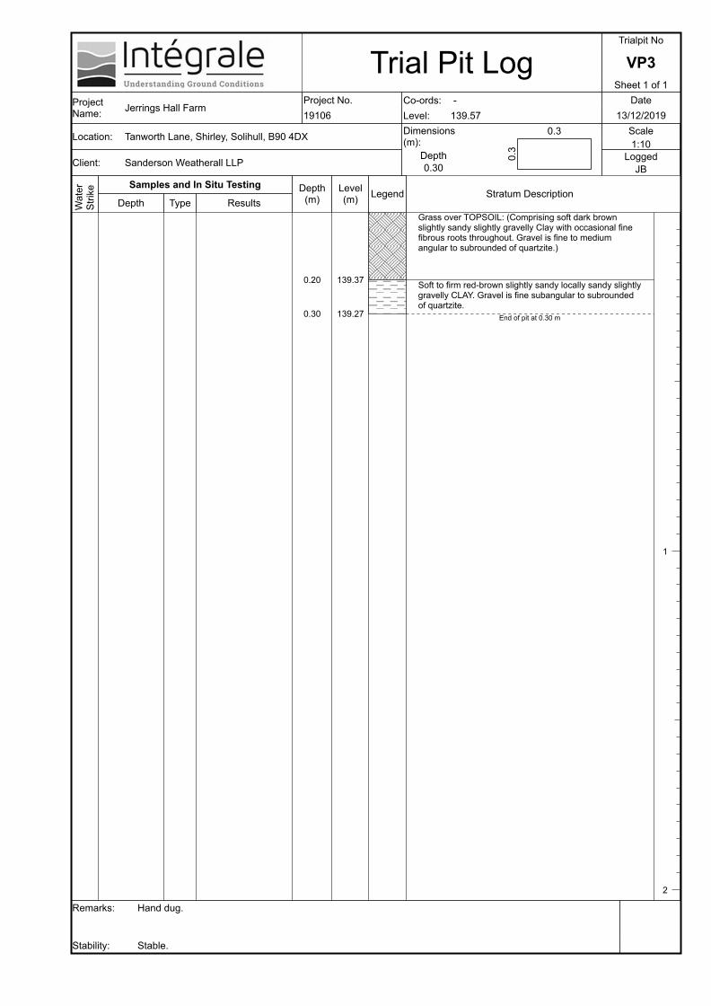
Grass over TOPSOIL: (Comprising soft dark brown slightly sandy slightly gravelly Clay with occasional fine fibrous roots throughout. Gravel is fine to medium angular to subrounded of quartzite.)
Soft to firm red-brown slightly sandy locally sandy slightly gravelly CLAY. Gravel is fine subangular to subrounded of quartzite.
End of pit at 0.30 m
1
2

Trial Pit LogTrialpit No
VP4Sheet 1 of 1
Project Name: Jerrings Hall Farm
Project No.19106
Co-ords:Level:
-139.28
Date13/12/2019
Location:
Client:
Tanworth Lane, Shirley, Solihull, B90 4DX
Sanderson Weatherall LLP
Dimensions (m):
Depth0.30
0.3
0.3 Scale1:10
LoggedJB
Remarks:
Stability:
Hand dug.
Stable.
Wat
erSt
rike Samples and In Situ Testing
Depth Type ResultsDepth
(m)
0.20
0.30
Level(m)
139.08
138.98
Legend Stratum Description
Grass over TOPSOIL: (Comprising soft dark brown slightly sandy slightly gravelly Clay with occasional fine fibrous roots throughout. Gravel is fine to medium angular to subrounded of quartzite.)
Soft to firm red-brown slightly sandy locally sandy slightly gravelly CLAY. Gravel is fine subangular to subrounded of quartzite.
End of pit at 0.30 m
1
2

Trial Pit LogTrialpit No
FP1Sheet 1 of 1
Project Name: Jerrings Hall Farm
Project No.19106
Co-ords:Level:
-139.51
Date16/12/2019
Location:
Client:
Tanworth Lane, Shirley, Solihull, B90 4DX
Sanderson Weatherall LLP
Dimensions (m):
Depth0.72
0.5
0.7 Scale1:10
LoggedJB
Remarks:
Stability:
Hand dug pit to investigate depth of foundation at rear of stable block.No groundwater encountered.
Stable.
Wat
erSt
rike Samples and In Situ Testing
Depth Type ResultsDepth
(m)
0.60
0.72
Level(m)
138.91
138.79
Legend Stratum Description
Scrub over MADE GROUND: (Comprising dark brown-grey slightly gravelly sandy Silt with high cobble content and fine fibrous roots to c.0.2m. Gravel is angular to subangular quartzite, brick and charcoal. Cobbles are angular brick and tile fragments.)
Soft brown slightly sandy slightly gravelly CLAY. Gravel is angular to subrounded fine to medium quartzite.(TILL)
End of pit at 0.72 m
1
2
0.30 ES
0.65 D

Trial Pit LogTrialpit No
FP2Sheet 1 of 1
Project Name: Jerrings Hall Farm
Project No.19106
Co-ords:Level:
-138.99
Date16/12/2019
Location:
Client:
Tanworth Lane, Shirley, Solihull, B90 4DX
Sanderson Weatherall LLP
Dimensions (m):
Depth0.50
0.25
0.35 Scale1:10
LoggedJB
Remarks:
Stability:
Hand dug pit to investigate depth of foundation at front of stable block.Seepage at base of pit.
Stable
Wat
erSt
rike Samples and In Situ Testing
Depth Type ResultsDepth
(m)
0.02
0.10
0.25
0.50
Level(m)
138.97
138.89
138.74
138.49
Legend Stratum Description
Sandstone FLAGS.Weak MORTAR.
MADE GROUND: (Comprising dark brown slightly sandy slightly gravelly Clay with rare roots up to 10mm diameter. Gravel is angular to subangular fine to medium brick, quartzite and rare ceramic.)
Firm grey-brown slightly sandy slightly gravelly CLAY with occasional fine roots up to 5mm diameter. Gravel is angular to subangular fine to medium quartzite. (TILL)
End of pit at 0.50 m
1
2
0.20 ES
0.40 D

GL
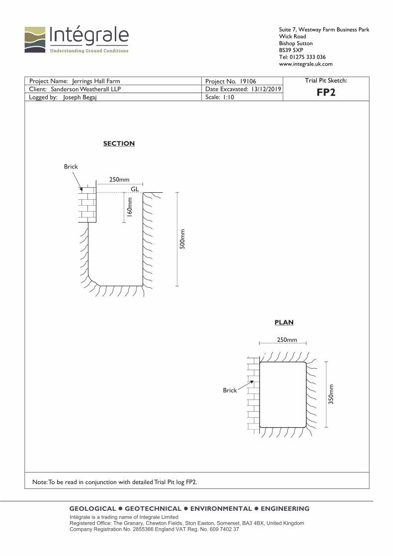
PLAN
Brickfooting
SECTION
Brick
Brickfooting
Brick
500mm
720m
m
210m
m
700m
m
500mm
490m
m
50mm
50mm
19106Sanderson Weatherall LLP
Joseph Begaj
Jerrings Hall Farm13/12/2019
1:10FP1
Note: To be read in conjunction with detailed Trial Pit log FP1.
GL
PLAN
SECTION
Brick
Brick
250mm50
0mm
160m
m
350m
m
250mm
19106Sanderson Weatherall LLP
Joseph Begaj
Jerrings Hall Farm13/12/2019
1:10FP2
Note: To be read in conjunction with detailed Trial Pit log FP2.
GEOLOGICAL • GEOTECHNICAL • ENVIRONMENTAL • ENGINEERING
Integrale Limited, Suite 7, Westway Farm Business Park, Wick Road, Bishop Sutton, Somerset, BS39 5XP United Kingdom Tel: 01275 333 036 www.integrale.uk.com
Registered Office: The Granary, Chewton Fields, Ston Easton, Somerset, BA3 4BX United Kingdom VAT Reg. No. 609 7402 37
Appendix D
Soakaway Analyses

Suite 7, Westway Farm Business Park Wick Road, Bishop Sutton, Somerset, BS39 5XP, United Kingdom Tel: 01275 333036 www.integrale.uk.com
GEOLOGICAL • GEOTECHNICAL • ENVIRONMENTAL • ENGINEERING
Intégrale is a trading name of Integrale Limited. Registered Office: The Granary, Chewton Fields, Ston Easton, Somerset, BA3 4BX United Kingdom Company Registration No. 2855366 England VAT Reg. No. 609 7402 37
STANDARD METHODOLOGY FOR SOAKAWAY TESTING
Some trial pits also include soakaway testing in order to assess the soils permeability for design of stormwater drainage. The soakaway tests were completed in accordance with BRE Digest 365 (September 1991). This included excavation of pits to generally 1-2m depth, which were then filled with water on one to three occasions depending on the rate of infiltration. The water was supplied by a water bowser and discharged into the pits using a centrifugal pump. The falling head was recorded and therefore the rate of infiltration into the soils beneath. The soakaway results have been prepared using a Microsoft Excel spreadsheet.

Job No:
BRE 365 (2007) Soakaway Design
Date of Test: 13/12/19 & 16/12/19
Length (m): 1.00 Width (m): 0.60 Depth (m): 1.60
Remarks:
Effective Storage Depth75-25% (m)
A = Surface Area50% (m2)
V = Effective Storage Volume75-25% (m3)
t = Time75-25% (mins)
Soil Infiltration Rate (m/s)
Sheet:
Date: 13/01/2020
SA1
1 of 113/01/2020
19106
Job Name: Jerrings Hall Farm Hole:
Soil Infiltration Rate Test
Checked By: AH
Test 1 Test 2 Test 3
The superficial soils were saturated and perched groundwater readily flowed into the pit throughout the tests, resulting in increasing
water levels..
Prepared By: JB Date:
N/A
0.34
1.66
0.20
N/A
0.33
1.66
Soil Infiltration Rate (m/s)
-
-
-
-
-
N/A
N/A N/A
0.20
0
0.1
0.2
0.3
0.4
0.5
0.6
0.7
0.8
0.9
1
0 60 120 180 240
De
pth
to
Wa
ter
(m)
Time (mins)
Test 1
Test 2
Suite 7, Westway Farm Business ParkWick Road
Bishop SuttonBS39 5XP
Tel: 01275 333 036www.integrale.uk.com
Tests abandoned
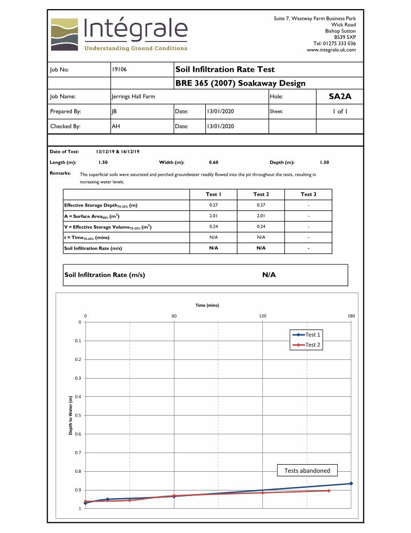
Job No:
BRE 365 (2007) Soakaway Design
Date of Test: 13/12/19 & 16/12/19
Length (m): 1.50 Width (m): 0.60 Depth (m): 1.50
Remarks:
Effective Storage Depth75-25% (m)
A = Surface Area50% (m2)
V = Effective Storage Volume75-25% (m3)
t = Time75-25% (mins)
Soil Infiltration Rate (m/s)
The superficial soils were saturated and perched groundwater readily flowed into the pit throughout the tests, resulting in
increasing water levels.
N/A N/A -
Soil Infiltration Rate (m/s) N/A
0.24 0.24 -
N/A N/A -
0.27 0.27 -
2.01 2.01 -
Test 1 Test 2 Test 3
Checked By: AH Date: 13/01/2020
Prepared By: JB Date: 13/01/2020 Sheet: 1 of 1
19106 Soil Infiltration Rate Test
Job Name: Jerrings Hall Farm Hole: SA2A
0
0.1
0.2
0.3
0.4
0.5
0.6
0.7
0.8
0.9
1
0 60 120 180
De
pth
to
Wa
ter
(m)
Time (mins)
Test 1
Test 2
Suite 7, Westway Farm Business ParkWick Road
Bishop SuttonBS39 5XP
Tel: 01275 333 036www.integrale.uk.com
Tests abandoned
Job No:
BRE 365 (2007) Soakaway Design
Date of Test: 13/12/19 & 16/12/19
Length (m): 1.40 Width (m): 0.85 Depth (m): 1.10
Remarks:
Effective Storage Depth75-25% (m)
A = Surface Area50% (m2)
V = Effective Storage Volume75-25% (m3)
t = Time75-25% (mins)
Soil Infiltration Rate (m/s)
The superficial soils were saturated and perched groundwater readily flowed into the pit throughout the tests, resulting in
increasing water levels.
N/A N/A -
Soil Infiltration Rate (m/s) N/A
0.36 0.36 -
N/A N/A -
0.31 0.31 -
2.56 2.56 -
Test 1 Test 2 Test 3
Checked By: AH Date: 13/01/2020
Prepared By: JB Date: 13/01/2020 Sheet: 1 of 1
19106 Soil Infiltration Rate Test
Job Name: Jerrings Hall Farm Hole: SA3
0
0.1
0.2
0.3
0.4
0.5
0 60 120 180
De
pth
to
Wa
ter
(m)
Time (mins)
Test 1
Test 2
Tests abandoned
Suite 7, Westway Farm Business ParkWick Road
Bishop SuttonBS39 5XP
Tel: 01275 333 036www.integrale.uk.com

Job No:
BRE 365 (2007) Soakaway Design
Date of Test: 13/12/19 & 16/12/19
Length (m): 1.10 Width (m): 0.60 Depth (m): 1.10
Remarks:
Effective Storage Depth75-25% (m)
A = Surface Area50% (m2)
V = Effective Storage Volume75-25% (m3)
t = Time75-25% (mins)
Soil Infiltration Rate (m/s)
The superficial soils were saturated and perched groundwater readily flowed into the pit throughout the tests, resulting in
increasing water levels.
N/A N/A -
Soil Infiltration Rate (m/s) N/A
0.21 0.21 -
N/A N/A -
0.33 0.34 -
1.77 1.77 -
Test 1 Test 2 Test 3
Checked By: AH Date: 13/01/2020
Prepared By: JB Date: 13/01/2020 Sheet: 1 of 1
19106 Soil Infiltration Rate Test
Job Name: Jerrings Hall Farm Hole: SA4
0
0.1
0.2
0.3
0.4
0.5
0 60 120 180
De
pth
to
Wa
ter
(m)
Time (mins)
Test 1
Test 2
Suite 7, Westway Farm Business ParkWick Road
Bishop SuttonBS39 5XP
Tel: 01275 333 036www.integrale.uk.com
Tests abandoned

Job No:
BRE 365 (2007) Soakaway Design
Date of Test: 13/12/19 & 16/12/19
Length (m): 1.20 Width (m): 0.60 Depth (m): 1.60
Remarks:
Effective Storage Depth75-25% (m)
A = Surface Area50% (m2)
V = Effective Storage Volume75-25% (m3)
t = Time75-25% (mins)
Soil Infiltration Rate (m/s)
The superficial soils were saturated and perched groundwater readily flowed into the pit throughout the tests, resulting in
increasing water levels.
N/A N/A -
Soil Infiltration Rate (m/s) N/A
0.23 0.23 -
N/A N/A -
0.31 0.36 -
1.85 1.85 -
Test 1 Test 2 Test 3
Checked By: AH Date: 13/01/2020
Prepared By: JB Date: 13/01/2020 Sheet: 1 of 1
19106 Soil Infiltration Rate Test
Job Name: Jerrings Hall Farm Hole: SA5A
0
0.1
0.2
0.3
0.4
0.5
0.6
0.7
0.8
0.9
1
0 60 120 180
De
pth
to
Wa
ter
(m)
Time (mins)
Test 1
Test 2
Suite 7, Westway Farm Business ParkWick Road
Bishop SuttonBS39 5XP
Tel: 01275 333 036www.integrale.uk.com
Tests abandoned

GEOLOGICAL • GEOTECHNICAL • ENVIRONMENTAL • ENGINEERING
Integrale Limited, Suite 7, Westway Farm Business Park, Wick Road, Bishop Sutton, Somerset, BS39 5XP United Kingdom Tel: 01275 333 036 www.integrale.uk.com
Registered Office: The Granary, Chewton Fields, Ston Easton, Somerset, BA3 4BX United Kingdom VAT Reg. No. 609 7402 37
Appendix E
Percolation Analyses
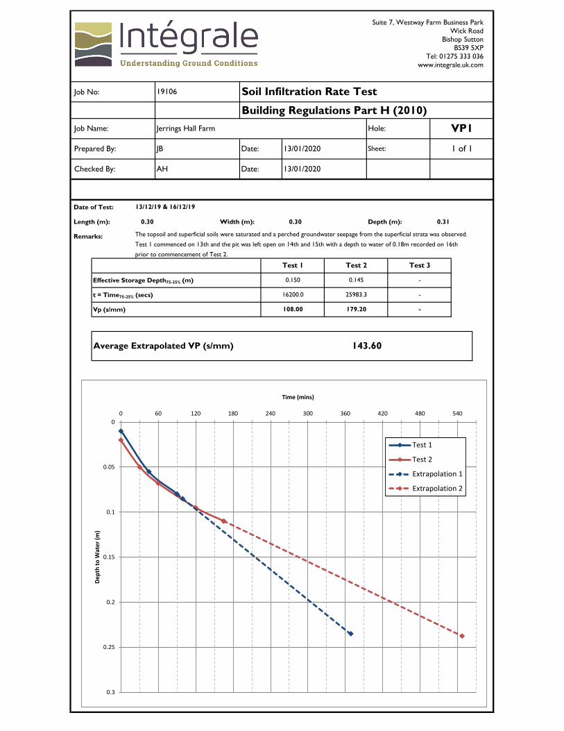
Job No:
Building Regulations Part H (2010)
Date of Test:
Length (m): 0.30 Width (m): 0.30 Depth (m): 0.31
Remarks:
Effective Storage Depth75-25% (m)
t = Time75-25% (secs)
Vp (s/mm)
19106 Soil Infiltration Rate Test
Job Name: Jerrings Hall Farm Hole: VP1
Prepared By: JB Date: 13/01/2020 Sheet: 1 of 1
Checked By: AH Date: 13/01/2020
13/12/19 & 16/12/19
Test 1 Test 2 Test 3
The topsoil and superficial soils were saturated and a perched groundwater seepage from the superficial strata was observed.
Test 1 commenced on 13th and the pit was left open on 14th and 15th with a depth to water of 0.18m recorded on 16th
prior to commencement of Test 2.
0.150 0.145 -
16200.0 25983.3 -
108.00 179.20 -
Average Extrapolated VP (s/mm) 143.60
0
0.05
0.1
0.15
0.2
0.25
0.3
0 60 120 180 240 300 360 420 480 540
De
pth
to
Wa
ter
(m)
Time (mins)
Test 1
Test 2
Extrapolation 1
Extrapolation 2
Suite 7, Westway Farm Business ParkWick Road
Bishop SuttonBS39 5XP
Tel: 01275 333 036www.integrale.uk.com
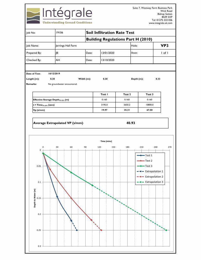
Job No:
Building Regulations Part H (2010)
Date of Test:
Length (m): 0.30 Width (m): 0.30 Depth (m): 0.33
Remarks: No groundwater encountered.
Effective Storage Depth75-25% (m)
t = Time75-25% (secs)
Vp (s/mm)
19106 Soil Infiltration Rate Test
Job Name: Jerrings Hall Farm Hole: VP3
Prepared By: JB Date: 13/01/2020 Sheet: 1 of 1
Checked By: AH Date: 13/10/2020
16/12/2019
Test 1 Test 2 Test 3
0.160 0.160 0.160
3195.0 5650.2 10800.0
19.97 35.31 67.50
Average Extrapolated VP (s/mm) 40.93
0
0.05
0.1
0.15
0.2
0.25
0.3
0 30 60 90 120 150 180 210 240 270
De
pth
to
Wa
ter
(m)
Time (mins)
Test 1
Test 2
Test 3
Extrapolation 1
Extrapolation 2
Extrapolation 3
Suite 7, Westway Farm Business ParkWick Road
Bishop SuttonBS39 5XP
Tel: 01275 333 036www.integrale.uk.com

Job No:
Building Regulations Part H (2010)
Date of Test:
Length (m): 0.30 Width (m): 0.30 Depth (m): 0.30
Remarks: No groundwater encountered.
Effective Storage Depth75-25% (m)
t = Time75-25% (secs)
Vp (s/mm)
19106 Soil Infiltration Rate Test
Job Name: Jerrings Hall Farm Hole: VP4
Prepared By: JB Date: 13/01/2020 Sheet: 1 of 1
Checked By: AH Date: 13/01/2020
16/12/2019
Test 1 Test 2 Test 3
0.145 - -
25875.0 - -
178.45 - -
Extrapolated VP (s/mm) 178.45
0
0.05
0.1
0.15
0.2
0.25
0.3
0 60 120 180 240 300 360 420 480
De
pth
to
Wa
ter
(m)
Time (mins)
Test 1
Extrapolation 1
Suite 7, Westway Farm Business ParkWick Road
Bishop SuttonBS39 5XP
Tel: 01275 333 036www.integrale.uk.com

GEOLOGICAL • GEOTECHNICAL • ENVIRONMENTAL • ENGINEERING
Integrale Limited, Suite 7, Westway Farm Business Park, Wick Road, Bishop Sutton, Somerset, BS39 5XP United Kingdom Tel: 01275 333 036 www.integrale.uk.com
Registered Office: The Granary, Chewton Fields, Ston Easton, Somerset, BA3 4BX United Kingdom VAT Reg. No. 609 7402 37
Appendix F
Dual Ring Infiltration Analyses
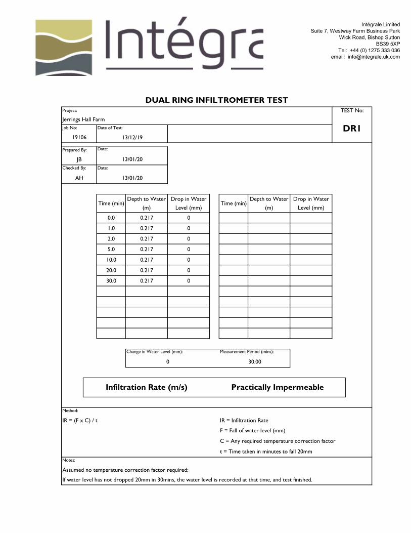
Intégrale LimitedSuite 7, Westway Farm Business Park
Wick Road, Bishop SuttonBS39 5XP
Tel: +44 (0) 1275 333 036email: [email protected]
Time (min)Depth to Water
(m)
Drop in Water
Level (mm)Time (min)
Depth to Water
(m)
Drop in Water
Level (mm)
0.0 0.217 0
1.0 0.217 0
2.0 0.217 0
5.0 0.217 0
10.0 0.217 0
20.0 0.217 0
30.0 0.217 0
Change in Water Level (mm): Measurement Period (mins):
Method:
IR = (F x C) / t IR = Infiltration Rate
F = Fall of water level (mm)
C = Any required temperature correction factor
t = Time taken in minutes to fall 20mmNotes:
Assumed no temperature correction factor required;
If water level has not dropped 20mm in 30mins, the water level is recorded at that time, and test finished.
AH 13/01/20
Infiltration Rate (m/s) Practically Impermeable
0 30.00
Prepared By: Date:
JB 13/01/20Checked By: Date:
DUAL RING INFILTROMETER TESTProject: TEST No:
Jerrings Hall Farm
DR1Job No: Date of Test:
19106 13/12/19

Intégrale LimitedSuite 7, Westway Farm Business Park
Wick Road, Bishop SuttonBS39 5XP
Tel: +44 (0) 1275 333 036email: [email protected]
Time (min)Depth to Water
(m)
Drop in Water
Level (mm)Time (min)
Depth to Water
(m)
Drop in Water
Level (mm)
0.0 0.210 0
1.0 0.210 0
5.0 0.212 2
10.0 0.212 0
20.0 0.214 2
30.0 0.215 1
Change in Water Level (mm): Measurement Period (mins):
Method:
IR = (F x C) / t IR = Infiltration Rate
F = Fall of water level (mm)
C = Any required temperature correction factor
t = Time taken in minutes to fall 20mmNotes:
Assumed no temperature correction factor required;
If water level has not dropped 20mm in 30mins, the water level is recorded at that time, and test finished.
DUAL RING INFILTROMETER TESTProject: TEST No:
Jerrings Hall Farm
DR2Job No: Date of Test:
19106 13/12/19
Prepared By: Date:
JB 13/01/20Checked By: Date:
AH 13/01/20
5 30.00
Infiltration Rate (m/s) 2.78E-06

Intégrale LimitedSuite 7, Westway Farm Business Park
Wick Road, Bishop SuttonBS39 5XP
Tel: +44 (0) 1275 333 036email: [email protected]
Time (min)Depth to Water
(m)
Drop in Water
Level (mm)Time (min)
Depth to Water
(m)
Drop in Water
Level (mm)
0.0 0.210 0
2.0 0.220 10
10.0 0.225 5
40.0 0.228 3
Change in Water Level (mm): Measurement Period (mins):
Method:
IR = (F x C) / t IR = Infiltration Rate
F = Fall of water level (mm)
C = Any required temperature correction factor
t = Time taken in minutes to fall 20mmNotes:
Assumed no temperature correction factor required;
If water level has not dropped 20mm in 30mins, the water level is recorded at that time, and test finished.
DUAL RING INFILTROMETER TESTProject: TEST No:
Jerrings Hall Farm
DR3Job No: Date of Test:
19106 16/12/19
Prepared By: Date:
JB 13/01/20Checked By: Date:
AH 13/01/20
18 40.00
Infiltration Rate (m/s) 7.50E-06

GEOLOGICAL • GEOTECHNICAL • ENVIRONMENTAL • ENGINEERING
Integrale Limited, Suite 7, Westway Farm Business Park, Wick Road, Bishop Sutton, Somerset, BS39 5XP United Kingdom Tel: 01275 333 036 www.integrale.uk.com
Registered Office: The Granary, Chewton Fields, Ston Easton, Somerset, BA3 4BX United Kingdom VAT Reg. No. 609 7402 37
Appendix G
Results of Geotechnical Laboratory Testing
Suite 7, Westway Farm Business Park Wick Road, Bishop Sutton, Somerset, BS39 5XP, United Kingdom Tel: 01275 333036 www.integrale.uk.com
GEOLOGICAL • GEOTECHNICAL • ENVIRONMENTAL • ENGINEERING
Intégrale is a trading name of Integrale Limited. Registered Office: The Granary, Chewton Fields, Ston Easton, Somerset, BA3 4BX United Kingdom Company Registration No. 2855366 England VAT Reg. No. 609 7402 37
STANDARD METHODOLOGY FOR GEOTECHNICAL SAMPLING
Soil samples are recovered from trial pits or borehole samples using a stainless steel trowel and immediately placed into airtight plastic tubs or bags, as appropriate for the testing. If required the soil samples may be wrapped in cling film, particularly in suspected desiccated soils. Samples are labelled with the site name, investigation location and depth and placed into either cool boxes or large bulk bags for transit from site. An analytical schedule is drawn up in line with the actual ground conditions proven, proposed site use and likely design parameters. Samples are sent to a specialist testing laboratory. Testing is completed in line with BS1377 as far as possible and details of the test method and UKAS accreditation are provided by the laboratory on the results sheets in a separate appendix.

NO
Ref.
David Trowbridge (Laboratory Manager)
Dan Ayre (Quality Manager)
Matt Stokes (Senior Technician)
Job No:
1
Date Received:
Job Name:
Client Name:
Client Job No:
Date Sent:
Transmittal Number:
Senders Initials:
Test Detail
A1 BS1377: Part 2: 1990: Clause 3 - Moisture Content - UKAS Accredited
A5 BS1377: Part 2: 1990: Clause 4 & 5 - Atterberg Limits - UKAS Accredited
Report Revision No. 2
Test Report
1
12144
Jerrings Hall Farm
Integrale
No. of Tests /
Report No.
19106
09/01/20
30/01/20
South West Geotechnical Ltd
Unit 3 Brooklands,
Howden Road,
Tiverton,
Devon
EX16 5HW
T5375
DT
Sampled by SWG lab staff?
The results contained within this report only relate to the samples tested, as received from the
client. This certificate shall not be reproduced except in full, without prior written approval of the
laboratory.
Sampling not performed by South West Geotechnical laboratory staff. Results apply to the samples as received.
8260
Accredited to
ISO/IEC
17025:2017
Approved Signatories:
Client Address Suite 7, Westway Farm Business Park, Wick Road, Bishop Sutton, Bristol, BS39 5XP
A9 BS1377: Part 2: 1990: Clause 9.2 / 9.3 - Particle Size Distribution - UKAS Accredited 2
3.6.1.3 Quality Forms/LQ016-03
Version 13 - DA
Issued 28/06/2019
T5375 Test Report & Valuation Page 1 of 1
12144 - T5375 - Results_v2.pdf Page 1 of 5
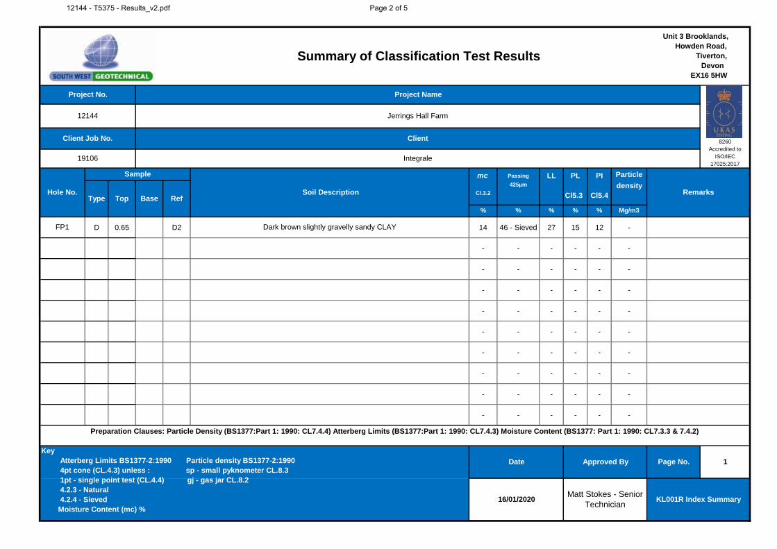
mc Passing LL PL PI Particle
Cl.3.2
425µm
Cl5.3 Cl5.4
density
% % % % % Mg/m3
D 0.65 D2 14 46 - Sieved 27 15 12 -
- - - - - -
- - - - - -
- - - - - -
- - - - - -
- - - - - -
- - - - - -
- - - - - -
- - - - - -
- - - - - -
Summary of Classification Test Results
Unit 3 Brooklands,
Howden Road,
Tiverton,
Devon
EX16 5HW
Project No. Project Name
12144 Jerrings Hall Farm
Client Job No. Client8260
Accredited to
ISO/IEC
17025:201719106 Integrale
Hole No.
Sample
Soil Description RemarksType Top Base Ref
FP1 Dark brown slightly gravelly sandy CLAY
1
16/01/2020Matt Stokes - Senior
TechnicianKL001R Index Summary
Preparation Clauses: Particle Density (BS1377:Part 1: 1990: CL7.4.4) Atterberg Limits (BS1377:Part 1: 1990: CL7.4.3) Moisture Content (BS1377: Part 1: 1990: CL7.3.3 & 7.4.2)
Key
Atterberg Limits BS1377-2:1990 Particle density BS1377-2:1990
4pt cone (CL.4.3) unless : sp - small pyknometer CL.8.3
1pt - single point test (CL.4.4) gj - gas jar CL.8.2
4.2.3 - Natural
4.2.4 - Sieved
Moisture Content (mc) %
Date Approved By Page No.
12144 - T5375 - Results_v2.pdf Page 2 of 5
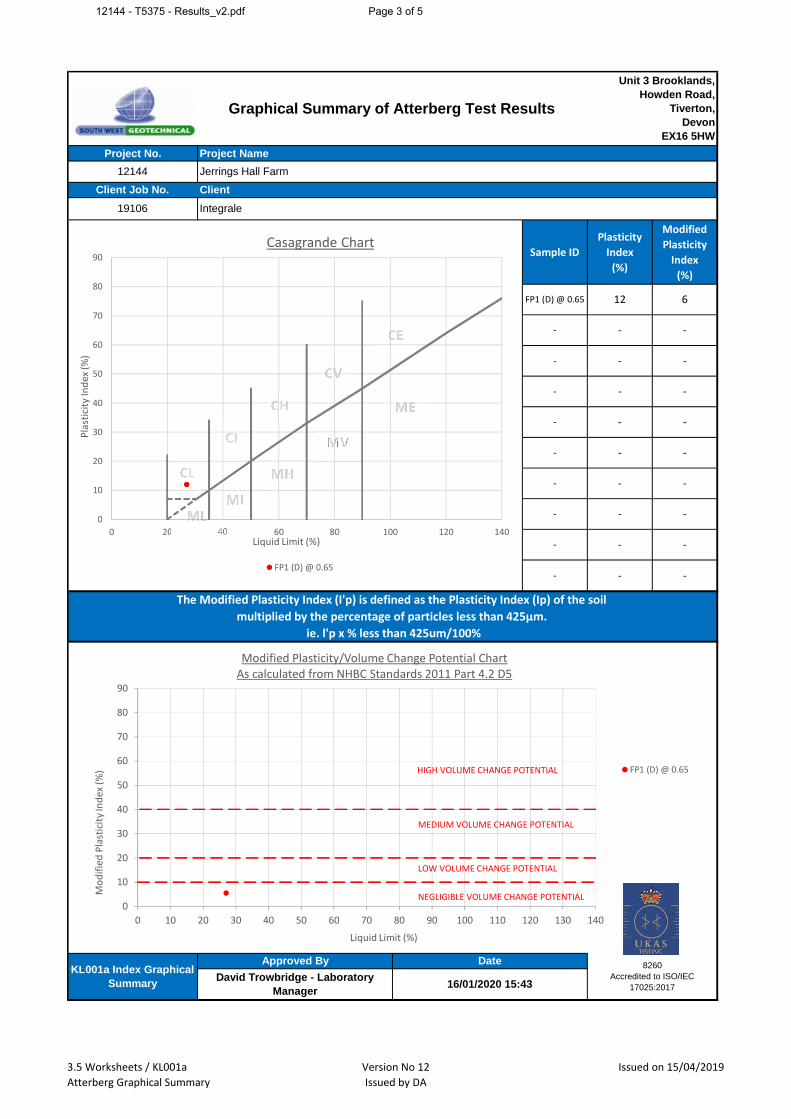
Sample ID
Plasticity
Index
(%)
Modified
Plasticity
Index
(%)
Date
16/01/2020 15:43
The Modified Plasticity Index (I'p) is defined as the Plasticity Index (Ip) of the soil
multiplied by the percentage of particles less than 425µm.
ie. l'p x % less than 425um/100%
- - -
KL001a Index Graphical
Summary
Approved By
- - -
- - -
- - -
- - -
- -
- - -
- - -
Graphical Summary of Atterberg Test Results
Project No.
19106
12144
Project Name
ClientClient Job No.
Unit 3 Brooklands,
Howden Road,
Tiverton,
Devon
EX16 5HW
Jerrings Hall Farm
Integrale
David Trowbridge - Laboratory
Manager
8260
Accredited to ISO/IEC
17025:2017
- - -
-
FP 1 (D)@ 0.65 12 6
0
10
20
30
40
50
60
70
80
90
0 20 40 60 80 100 120 140
Pla
stic
ity
Ind
ex(%
)
L iquidL im it(% )
CasagrandeChart
FP 1 (D)@ 0.65
MV
0
10
20
30
40
50
60
70
80
90
0 10 20 30 40 50 60 70 80 90 100 110 120 130 140
Mo
dif
ied
Pla
stic
ity
Ind
ex(%
)
L iquidL im it(% )
M odifiedP lasticity/Volum eChangeP otentialChartAscalculatedfrom N HBC S tandards2011 P art4.2 D5
FP 1 (D)@ 0.65HIGH VO L U M ECHAN GEP O T EN T IAL
M EDIU M VO L U M ECHAN GEP O T EN T IAL
L O W VO L U M ECHAN GEP O T EN T IAL
N EGL IGIBL EVO L U M ECHAN GEP O T EN T IAL
3.5 W orksheets/KL 001a
AtterbergGraphicalS um m ary
VersionN o12
Issuedby DA
Issuedon15/04/2019
12144 - T5375 - Results_v2.pdf Page 3 of 5

3.45
mm
mm
mm
mm
PARTICLE SIZE DISTRIBUTIONProject No. 12144
Borehole/Pit No. TP1
Project Name Jerrings Hall Farm Sample No. D3
Soil Description Brown silty/clayey very sandy GRAVEL Depth, m 0.50
Specimen
Reference1
Specimen
Depthm Sample Type D
Test Method BS1377:Part 2:1990, clause 9.2
Sieving SedimentationDry Mass of sample, g 1757
Particle Size
mm% Passing
Particle Size
mm% Passing
125 100 Sample Proportions % dry mass
90 100 Very coarse 0
75 100 Gravel 61
63 100 Sand 28
50 100
37.5 100 Fines <0.063mm 11
28 91
20 74 Grading Analysis
14 64 D100
10 55 D60 12.1
6.3 47 D30 0.412
5 45 D10
3.35 42 Uniformity Coefficient
2 39 Curvature Coefficient
1.18 37
0.63 35 Remarks
0.425 31 Preparation and testing in accordance with
BS1377 unless noted below0.3 21
0.2 15 Preparation and testing in accordance with
BS1377 - Deviation to standard as insufficient
material provided in order to meet the
minimum mass requirement
0.15 13
0.063 11
8260
Accredited to
ISO/IEC
17025:2017
Approved by Date Sheet ID:
Matt Stokes - Senior Technician 16/01/2020KL002R
PSD
÷÷
ø
ö
çç
è
æ
1m
m
SILT
Fine Medium Coarse
SAND
Fine Medium Coarse
GRAVEL
Fine Medium CoarseCLAY COBBLES BOULDERS
0
10
20
30
40
50
60
70
80
90
100
0.001 0.01 0.1 1 10 100 1000
Perc
enta
ge P
assin
g %
Particle Size mm
12144 - T5375 - Results_v2.pdf Page 4 of 5
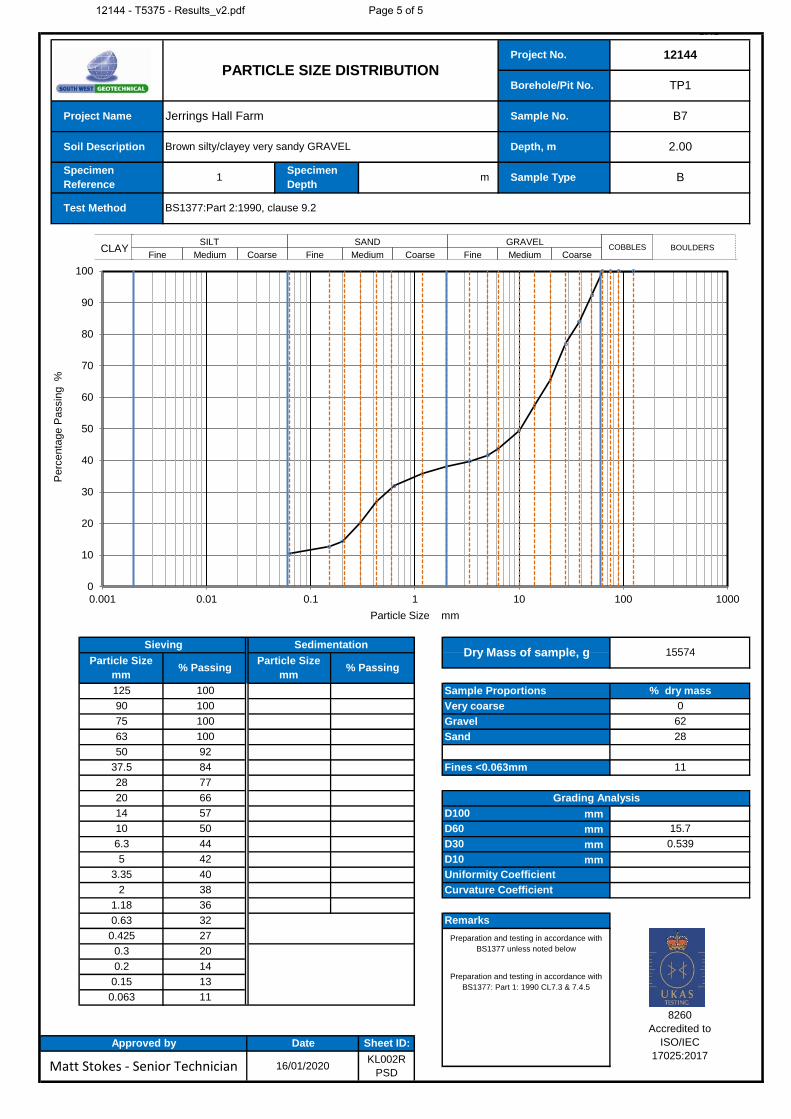
3.45
mm
mm
mm
mm
PARTICLE SIZE DISTRIBUTIONProject No. 12144
Borehole/Pit No. TP1
Project Name Jerrings Hall Farm Sample No. B7
Soil Description Brown silty/clayey very sandy GRAVEL Depth, m 2.00
Specimen
Reference1
Specimen
Depthm Sample Type B
Test Method BS1377:Part 2:1990, clause 9.2
Sieving SedimentationDry Mass of sample, g 15574
Particle Size
mm% Passing
Particle Size
mm% Passing
125 100 Sample Proportions % dry mass
90 100 Very coarse 0
75 100 Gravel 62
63 100 Sand 28
50 92
37.5 84 Fines <0.063mm 11
28 77
20 66 Grading Analysis
14 57 D100
10 50 D60 15.7
6.3 44 D30 0.539
5 42 D10
3.35 40 Uniformity Coefficient
2 38 Curvature Coefficient
1.18 36
0.63 32 Remarks
0.425 27 Preparation and testing in accordance with
BS1377 unless noted below0.3 20
0.2 14Preparation and testing in accordance with
BS1377: Part 1: 1990 CL7.3 & 7.4.50.15 13
0.063 11
8260
Accredited to
ISO/IEC
17025:2017
Approved by Date Sheet ID:
Matt Stokes - Senior Technician 16/01/2020KL002R
PSD
÷÷
ø
ö
çç
è
æ
1m
m
SILT
Fine Medium Coarse
SAND
Fine Medium Coarse
GRAVEL
Fine Medium CoarseCLAY COBBLES BOULDERS
0
10
20
30
40
50
60
70
80
90
100
0.001 0.01 0.1 1 10 100 1000
Perc
enta
ge P
assin
g %
Particle Size mm
12144 - T5375 - Results_v2.pdf Page 5 of 5
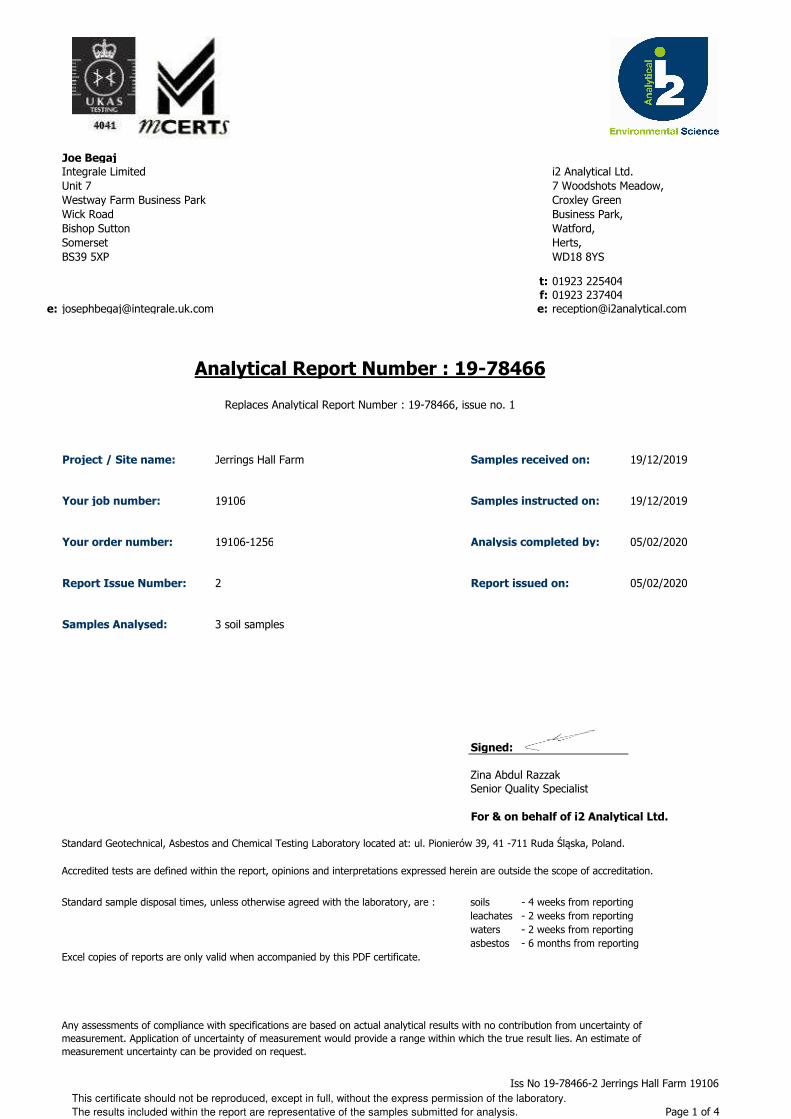
Joe Begaj
t: 01923 225404f: 01923 237404
e: [email protected] e:
Project / Site name: Samples received on: 19/12/2019
Your job number: 19106 Samples instructed on: 19/12/2019
Your order number: 19106-1256 Analysis completed by: 05/02/2020
Report Issue Number: 2 Report issued on: 05/02/2020
Samples Analysed:
Signed:
Senior Quality Specialist
For & on behalf of i2 Analytical Ltd.
Standard Geotechnical, Asbestos and Chemical Testing Laboratory located at: ul. Pionierów 39, 41 -711 Ruda Śląska, Poland.
Accredited tests are defined within the report, opinions and interpretations expressed herein are outside the scope of accreditation.
Standard sample disposal times, unless otherwise agreed with the laboratory, are : soils - 4 weeks from reportingleachates - 2 weeks from reportingwaters - 2 weeks from reportingasbestos - 6 months from reporting
Excel copies of reports are only valid when accompanied by this PDF certificate.
Any assessments of compliance with specifications are based on actual analytical results with no contribution from uncertainty of measurement. Application of uncertainty of measurement would provide a range within which the true result lies. An estimate of measurement uncertainty can be provided on request.
3 soil samples
Jerrings Hall Farm
Zina Abdul Razzak
Integrale LimitedUnit 7Westway Farm Business ParkWick RoadBishop SuttonSomersetBS39 5XP
i2 Analytical Ltd.7 Woodshots Meadow,Croxley Green Business Park,Watford, Herts, WD18 8YS
Replaces Analytical Report Number : 19-78466, issue no. 1
Analytical Report Number : 19-78466
This certificate should not be reproduced, except in full, without the express permission of the laboratory.
The results included within the report are representative of the samples submitted for analysis.
Iss No 19-78466-2 Jerrings Hall Farm 19106
Page 1 of 4

Analytical Report Number: 19-78466
Project / Site name: Jerrings Hall Farm
Your Order No: 19106-1256
Lab Sample Number 1397899 1397900 1397901Sample Reference TP1 TP1 FP2Sample Number D4 B7 D2Depth (m) 0.75 2.00 0.40Date Sampled 16/12/2019 16/12/2019 16/12/2019Time Taken None Supplied None Supplied None Supplied
Analytical Parameter
(Soil Analysis)
Un
its
Lim
it of
de
tectio
n
Accre
dita
tion
Sta
tus
Stone Content % 0.1 NONE < 0.1 < 0.1 < 0.1Moisture Content % N/A NONE 12 7.9 11Total mass of sample received kg 0.001 NONE 0.97 0.92 1.1
General Inorganics
pH - Automated pH Units N/A MCERTS 5.5 7.2 8.4Total Sulphate as SO4 % 0.005 MCERTS 0.026 0.015 0.050Water Soluble SO4 16hr extraction (2:1 Leachate Equivalent) g/l 0.00125 MCERTS 0.023 0.014 0.071Water Soluble SO4 16hr extraction (2:1 Leachate Equivalent) mg/l 1.25 MCERTS 22.8 13.8 71.0Total Sulphur % 0.005 MCERTS 0.010 0.008 0.071
This certificate should not be reproduced, except in full, without the express permission of the laboratory.
The results included within the report are representative of the samples submitted for analysis.
Iss No 19-78466-2 Jerrings Hall Farm 19106
Page 2 of 4

Analytical Report Number : 19-78466
Project / Site name: Jerrings Hall Farm
Lab Sample
Number
Sample
Reference
Sample
NumberDepth (m) Sample Description *
1397899 TP1 D4 0.75 Brown loam and clay with gravel and vegetation.1397900 TP1 B7 2.00 Brown clay and sand with gravel.1397901 FP2 D2 0.40 Brown clay and sand with gravel.
* These descriptions are only intended to act as a cross check if sample identities are questioned. The major constituent of the sample is intended to act with respect to MCERTS validation. The laboratory is accredited for sand, clay and loam (MCERTS) soil types. Data for unaccredited types of solid should be interpreted with care.
Stone content of a sample is calculated as the % weight of the stones not passing a 10 mm sieve. Results are not corrected for stone content.
This certificate should not be reproduced, except in full, without the express permission of the laboratory.
The results included within the report are representative of the samples submitted for analysis.
Iss No 19-78466-2 Jerrings Hall Farm 19106
Page 3 of 4
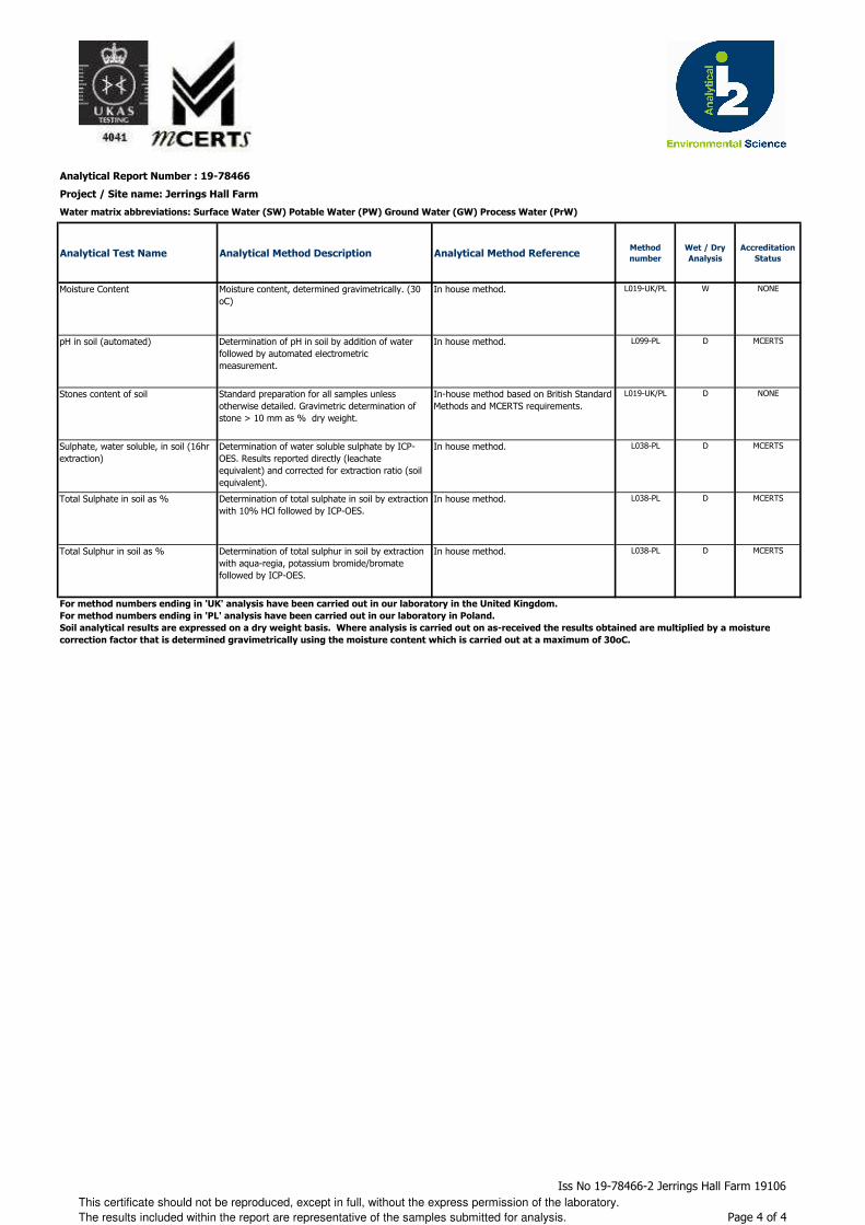
Analytical Report Number : 19-78466
Project / Site name: Jerrings Hall Farm
Water matrix abbreviations: Surface Water (SW) Potable Water (PW) Ground Water (GW) Process Water (PrW)
Analytical Test Name Analytical Method Description Analytical Method ReferenceMethod
number
Wet / Dry
Analysis
Accreditation
Status
Moisture Content Moisture content, determined gravimetrically. (30 oC)
In house method. L019-UK/PL W NONE
pH in soil (automated) Determination of pH in soil by addition of water followed by automated electrometric measurement.
In house method. L099-PL D MCERTS
Stones content of soil Standard preparation for all samples unless otherwise detailed. Gravimetric determination of stone > 10 mm as % dry weight.
In-house method based on British Standard Methods and MCERTS requirements.
L019-UK/PL D NONE
Sulphate, water soluble, in soil (16hr extraction)
Determination of water soluble sulphate by ICP-OES. Results reported directly (leachate equivalent) and corrected for extraction ratio (soil equivalent).
In house method. L038-PL D MCERTS
Total Sulphate in soil as % Determination of total sulphate in soil by extraction with 10% HCl followed by ICP-OES.
In house method. L038-PL D MCERTS
Total Sulphur in soil as % Determination of total sulphur in soil by extraction with aqua-regia, potassium bromide/bromate followed by ICP-OES.
In house method. L038-PL D MCERTS
For method numbers ending in 'UK' analysis have been carried out in our laboratory in the United Kingdom.
For method numbers ending in 'PL' analysis have been carried out in our laboratory in Poland.
Soil analytical results are expressed on a dry weight basis. Where analysis is carried out on as-received the results obtained are multiplied by a moisture
correction factor that is determined gravimetrically using the moisture content which is carried out at a maximum of 30oC.
This certificate should not be reproduced, except in full, without the express permission of the laboratory.
The results included within the report are representative of the samples submitted for analysis.
Iss No 19-78466-2 Jerrings Hall Farm 19106
Page 4 of 4
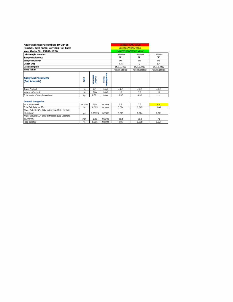
Analytical Report Number: 19-78466
Project / Site name: Jerrings Hall Farm
Your Order No: 19106-1256
Lab Sample Number 1397899 1397900 1397901
Sample Reference TP1 TP1 FP2
Sample Number D4 B7 D2
Depth (m) 0.75 2 0.4
Date Sampled 16/12/2019 16/12/2019 16/12/2019
Time Taken None Supplied None Supplied None Supplied
Analytical Parameter
(Soil Analysis)
Un
its
Lim
it of
de
tectio
n
Accre
dita
tion
Sta
tus
Stone Content % 0.1 NONE < 0.1 < 0.1 < 0.1
Moisture Content % N/A NONE 12 7.9 11
Total mass of sample received kg 0.001 NONE 0.97 0.92 1.1
General Inorganics
pH - Automated pH Units N/A MCERTS 5.5 7.2 8.4
Total Sulphate as SO4 % 0.005 MCERTS 0.026 0.015 0.05
Water Soluble SO4 16hr extraction (2:1 Leachate
Equivalent) g/l 0.00125 MCERTS 0.023 0.014 0.071
Water Soluble SO4 16hr extraction (2:1 Leachate
Equivalent) mg/l 1.25 MCERTS 22.8 13.8 71
Total Sulphur % 0.005 MCERTS 0.01 0.008 0.071
Exceeds GAC Value
Exceeds WRAS Value
Exceeds Phytotoxic Value

GEOLOGICAL • GEOTECHNICAL • ENVIRONMENTAL • ENGINEERING
Integrale Limited, Suite 7, Westway Farm Business Park, Wick Road, Bishop Sutton, Somerset, BS39 5XP United Kingdom Tel: 01275 333 036 www.integrale.uk.com
Registered Office: The Granary, Chewton Fields, Ston Easton, Somerset, BA3 4BX United Kingdom VAT Reg. No. 609 7402 37
Appendix H
Results of Gas & Groundwater Monitoring
Suite 7, Westway Farm Business Park Wick Road, Bishop Sutton, Somerset, BS39 5XP, United Kingdom Tel: 01275 333036 www.integrale.uk.com
GEOLOGICAL • GEOTECHNICAL • ENVIRONMENTAL • ENGINEERING
Intégrale is a trading name of Integrale Limited. Registered Office: The Granary, Chewton Fields, Ston Easton, Somerset, BA3 4BX United Kingdom Company Registration No. 2855366 England VAT Reg. No. 609 7402 37
STANDARD METHODOLOGIES FOR STANDPIPE INSTALLATIONS, SAMPLING and MONITORING FOR GAS AND GROUNDWATER Standpipe Installations in Trial Pits Simple 30-50mm diameter plastic standpipes are installed in trial pits during backfilling. These consist of slotted pipe throughout the buried length to within 0.5m of the ground surface, with unslotted pipe above. These are capped off with removable stop-ends above ground level. They provide a useful guide to soil gas conditions within the backfilled trial pit, however some soil gas will be lost by dispersal within the loose backfill at the surface of the pit. They are commonly used for monitoring standing groundwater levels which would develop within excavations, however careful consideration has to be given to the possible infiltration of rainfall and throughflow into the sump created by the excavated pit. Standpipe Installations in Boreholes Simple standpipes to measure the hydrostatic head of groundwater are formed in boreholes using 50mm diameter pipe. The details of individual installations are provided on borehole records. Typically the lower length is formed in slotted pipe, with the upper 1m unslotted. The annulus between the riser pipe and the borehole wall is filled with clean granular material. Details of any bentonite seals or grouting are given on the borehole records. A removable gas tap is fitted where gas monitoring is required and standpipes typically have a metal access cover concreted in at ground level. Standpipe piezometers are formed by using a Casagrande type piezometer tip at the base of the pipe, set in a granular response zone of sand or pea gravel. The response zone is isolated from the strata above and below by placing 500mm thick bentonite seals. The remaining annulus above the bentonite seal is filled with a cement bentonite grout or similar. Groundwater Monitoring & Sampling Details of return monitoring visits are included in this appendix. Groundwater standing levels are measured by inserting an electrically operated dip meter into the standpipe and recording the level to 2 decimal places, relative to existing ground level. Where groundwater levels are critical to calculation of hydraulic gradients or flow directions, the measurement is taken to 3 decimal places and to a marked point on the standpipe cover. That point is then surveyed and levelled to provide accurate calculations. Groundwater samples are recovered using either Waterra valves and sample tubing or by manually lifting water from the standpipe using a bailer. For contamination analyses, the boreholes are initially purged by removing up to 3 borehole volumes of water, allowing the rest level to redevelop and taking a sufficient sample into custom containers. If groundwater does not recover sufficiently, the purged water may be used as the sample. Gas Monitoring Monitoring is usually completed in standpipes prior to groundwater measurements, using portable instruments. Details are given on the monitoring tables, and typically using a PhoCheck Tiger photoionisation detector to measure volatile organic compounds in ppm and a GA5000 Gas meter to measure oxygen, carbon dioxide and methane, both by % Lower Explosive Limit and % Volume. Atmospheric pressure and temperature are also recorded. Measurements are taken immediately on opening the gas valve and the highest to lowest levels recorded. If levels fluctuate, then this is recorded, with the maximum reading and a more typical or rest level given.

Site
Client
Date
Oxygen VOCProduct
Thickness
(%/vol) (ppm) (mm)
0 0.1
30 0.2
60 0.2
0 0.1
30 0.1
60 0.2
0 -
30 -
60 -
0 0.1
30 0.2
60 0.2
0 0.1
30 0.2
60 0.2
0.0 - 0.61 - 0.71
Comments:
- 0.60 - 0.8
Comments:
SA5A 0.0 0.0 0.0 22.4
SA4 0.0 0.0 0.0 23.0 0.0
- - 0.10 - 0.65
Comments:
- 0.70 - 1.23
Comments:
SA3 - - - -
0.86 - 1.36
Comments:
SA2A 0.0 0.0 0.1 23.2 0.0
Depth to
Product
(mbgl)
Depth to
Water
(mbgl)
Well Depth
(mbgl)
SA1 0.0 0.0 0.0 22.1 0.0 -
Air Temperature 6°C Ground Conditions Wet
Position ID
Time
Elapsed
(secs)
Gas Flow
(l/hr)%LEL
Methane
(%/vol)
Carbon
Dioxide
(%/vol)
Friday, January 24, 2020 Visit No 1
Weather Cold & Overcast Atmospheric Pressure (mbar) 1004-1006
Suite 7, Westway Farm Business ParkWick Road, Bishop Sutton, Somerset, BS39 5XP, United Kingdom
Tel: 01275 333036www.integrale.uk.com
Jerrings Hall Farm Job No. 19106
Sanderson Weatherall LLP Monitored By JB

GEOLOGICAL • GEOTECHNICAL • ENVIRONMENTAL • ENGINEERING
Integrale Limited, Suite 7, Westway Farm Business Park, Wick Road, Bishop Sutton, Somerset, BS39 5XP United Kingdom Tel: 01275 333 036 www.integrale.uk.com
Registered Office: The Granary, Chewton Fields, Ston Easton, Somerset, BA3 4BX United Kingdom VAT Reg. No. 609 7402 37
Appendix I
Proposed Redevelopment

TP
TP
LPLP
GU
GU
GU
GU
GU
GU
GU
GU
GU
GU
GU
GU
GU
GU
GU
GU
GU
GU
GUGU
MH
MH
MH
MH
MH
MH
MH
MH
MH
MH
BT
BT
SP
SP
SV
SV
SV
SV
Stmp
Stmp
Stmp
Stmp
Stmp
Stmp
Stmp
Stmp
FH
Eave
Eave
Eave
Eave
Eave
Eave
EaveEave
Eave
Eave
Eave
Eave
Eave
Eave
Eave
Eave Eave
Eave
Eave
Eave
Eave
Eave
Eave
Ridg
Ridg
Ridg
Ridg
RidgRidg
Ridg
Ridg
Ridg
Ridg
Ridg
Ridg
Ridg
RidgRidg
VPgl
IC
IC
IC
IC
IC
ICIC
ICIC
IC
IC
IC
IC
post
post RP
GU
GU
GU
EP
CO
GAS
EC
EC
w.l.
invt
ST01137.642
ST02139.139
276250N 276250N
276300N 276300N
276350N 276350N
276400N 276400N
137.11
137.36
137.49
137.61
137.72
137.81
137.87
137.94
138.00
138.01
137.08
136.97
136.86
136.64
136.55
136.43
137.28
137.02
136.86
136.57
136.45
136.42
136.47
136.53
136.57
136.40
136.45
136.50
136.51
136.73136.81
136.75
136.53
136.74
136.39
136.60
136.35
136.33
136.34
136.67
136.57
137.00
136.84
137.56
137.
57
137.01
137.17
137.41
137.47
137.91
138.15
137.78
137.79
137.88
138.08
138.24
138.58
138.64
138.79139.00
138.71
138.40
138.40
138.05
137.85
137.86
137.75
137.66
137.95
138.02
138.25137.76
137.79
138.30
138.33
138.00
137.82
138.36
137.97
137.78
138.16
138.17
138.14
137.97
137.86
137.72
137.12
136.95
136.96
136.40136.38
136.41136.14
136.35
136.24
136.38
136.47
136.67
137.01
137.36
137.55
137.70
137.85
137.64
137.32
136.98
137.17
137.56
138.00
138.24
138.31
138.40
138.33
138.22
138.30
138.54138.94
138.66
136.93
137.05
136.67
136.96
136.95
136.81
136.64
136.93
136.98
137.03
137.22
137.17
141.21
143.21
146.18
143.21
141.24
139.31
138.40
138.37
137.95
137.37
136.97
136.78137.16
137.52
137.95138.40
138.52
138.11
137.78
137.45
137.10
136.73
136.75
137.06
137.30
137.55
137.77
137.92
137.81
137.80
137.60
137.36
137.19
136.82
136.75
136.96
137.19
137.28
137.54
137.73
137.88
137.67
137.92
138.05
138.10138.34
138.65
138.70
138.64
138.62
138.94
138.96
139.11
139.10
139.08
139.11139.11
138.83
138.78
138.70
138.75
138.75138.73
138.77
138.80
138.88
138.79
138.58
138.60
138.40138.33
138.25
138.39
138.26
138.23
137.96
137.98
138.22
138.35
138.27
138.50
138.63
138.60
138.77
138.79
138.80
138.80
138.66
138.56
138.57138.86
139.02
138.93
138.88
138.87
138.86
139.01
139.04
139.14
139.16
139.26
139.20139.20
139.28
139.22
139.05
139.22
139.11
139.19
139.08
139.07
139.26
139.12
139.07
138.98
138.89
138.96
139.12 139.06138.85
138.98
138.80
138.62
138.82
138.40
138.47
138.45
138.17
138.22
138.30
138.10
138.33
138.67
138.51
138.59
138.42
138.67
138.85
138.83
139.20
139.07
139.31
139.49
139.62
139.44
139.38
139.65
139.73
139.
73
139.69
139.65
139.58
139.38
139.27
139.06
138.65
138.68
138.62
138.35
138.21
138.16
138.93
138.91
139.23
143.52
144.05
145.26
147.53
147.96
144.42143.26
142.58140.97
143.25
141.15
142.35
146.86
143.78
141.60
145.56143.10
139.23
139.10139.17
139.09 139.01
138.89
139.18
138.80
139.01
139.13
138.81138.84
139.12
139.02
139.03
139.16
139.02
139.00
139.20
139.21
139.12
139.34
139.59
139.55
139.43
139.44
138.99
138.90
139.00
138.99 138.91
138.81
138.89
139.89
139.48
139.77
139.74
139.65
139.64
139.64
139.66
139.74
139.64
139.58
139.27
139.69
139.79
139.69
139.69
139.68
139.
73
139.70
139.49
139.62
139.51139.47
139.80
139.81139.77
139.72139.79
139.81
139.84
139.82
139.78
139.77
139.74
139.71
139.74
139.80
139.74
139.51
139.55
139.26
139.49
139.66
139.72
139.51
143.73
140.82
143.31 141.12141.98
138.77138.78
138.75
139.07
138.85
138.78
138.87
138.75
138.76
138.70
138.82
138.88
138.89
139.04
139.13
139.05
139.32
138.90
139.23
139.19
139.90
139.28
139.
46
138.81
138.89 138.88
138.96
138.95
138.84
138.78
138.68
139.00
138.91139.03
139.01
138.89
139.28
139.12
139.
03
138.98139.01
139.15
139.03
139.02
139.19
139.03138.97
139.08
139.09
139.28
139.
28
138.51
140.14
140.21
139.05
139.36
141.62 143.85
138.69
139.02
138.43
139.69139.69139.27
139.47
139.63
139.26
139.15
139.34139.46
139.89
139.73
139.41
140.09
140.22
139.99
139.50
144.02
147.52
146.81143.49
142.18
145.19 143.04
141.61143.86
139.45
139.31
139.43
139.34
139.25
139.27139.09
139.36
139.29
139.28
139.00
139.15
139.38139.50
139.20139.18
139.24
139.35
139.48
139.61
139.60
139.61
139.61
139.47
139.36
139.42
139.48
139.56
139.55
139.36
139.36
139.18
139.57139.29
139.31
139.20
139.16
139.33
139.36
139.57
139.34
139.39
139.44
139.44
139.40
139.34
139.59
139.47
138.9
4
139.63
139.84
139.70
138.21
138.82
139.37
139.33
139.30
139.67
139.68
139.73
139.17
139.14
Paddock
Paddock
Stable
Stable
Gravel
Gravel
Gravel
Gravel
Gravel
Grass
Grass
Grass
Grass
Grass
Paving
Paving
Paving
Paving
Paving
Paving
PavingPaving
Pavi
ng
Pond
SummerHouse
Lawn
ramp
Grass
Tanworth Lane
Tanworth Lane
137
137
137
138
138
138
138
138
138
138
138
139
139
139
139
139
139
139
139
139
139
139
139
140
140
276250N
276300N
276350N
276400N
Stmp
NEW PARKING AREA FOR 40 VEHICLESGrasscrete or similar low visual impact surface
NEW SHED
NEW TAXI DROP OFF POINT10 SPACES
IMPROVEMENT WORKS TO ACCESSFor details of access/visibilty refer to Highway Engineer Drwgs
4no. Ex. Trees removed
NEW MODULAR BUILDINGAdditional Teaching Space GIA 1,500 ft2
REPLACEMENT SHED 1
REPLACEMENT SHED 2
NEW SHED
NEW CCTV POLE
NEW CCTV
SEWERAGE TREATMENT PLANT (indicative location)
HARDSTANDING FOR BINS
NEW MODULAR BUILDINGAdditional Teaching Space equal to Stable
NEW FENCING & GATES TO PERIMETER OF SCHOOL AREAS AND POND
NEW FENCING & GATES TO PERIMETER OF SCHOOL AREAS AND POND
NEW FENCING & GATES TO PERIMETER OF SCHOOL AREAS AND POND
26 Martingate Corsham WiltshireSN13 0HL
18.1831.SK02
Copyright. Check all dimensions on site. This drawing is only to beused on the site for which designed.
Drawn:
1:250
Checked:PDR
Tel. 01249 701333Fax. 01249 [email protected]
E@ A0The Island ProjectJan 19
Jerrings Hall Farm Proposed Site Plan
Date:
Project:
Client: Scale:
Drawing:
Do not scale this drawing.Rev:
Date: Dr/Ch: Description:04/02/2019A Modular Bld location and caprparking layout amended following client MtgPDR27/03/2019B Footpath amendedPDR01/08/2019C Modular Building reduced in size and additional modular building added.PDR20/11/2019D Amended following client commentsPDR03/12/2019E Modular Building rotated 90 degrees, externals amended to suit.PDR
10
1:50
0 105m
1:500
2m0 4
20 1m
1:1001:200
0 10m 20
0 20m 40
1:12501:2500
0.5m
200mm0 400
400 20mm
1:2
1000
1:5
0 200100mm
1:10
50mm
Scale Bars1:20
154.87
157.08STN
Survey Key:-BO BollardBB Belisha BeaconBT BT CoverCB Telephone Control BoxCH Coal HoleCO Unidentified CoverConc ConcreteEP Electricity PoleFH Fire HydrantFT Face Profile TargetFW Foul Water Drain CoverGU Drainage Gully CoverGV Gas ValveGas Gas CoverIC Inspection Chamber Cover
154.87TP
154.87BH
WL 154.8721/01/10
154.87
10.00
Survey Control Station
Trial Pit
Borehole
Water Level(with date measured)
Spot Level
Tree (spread to scale)
LinetypesFenceline
Electricity Transmission Line
Hedge
Rock Face
Embankment Slope
Contour Lines
Gas Pipeline
Water Pipeline
LB Letter BoxLP Lamp PostMC Metal Drainage ChannelMH Manhole Cover (round)MP Marker PostRwp Rain Water PipeSV Water Stop ValveSW Storm Water Drain CoverTCB Telephone Call BoxTL Traffic LightTP Telegraph PoleTV Cable TV CoverWM Water Meter Cover Contours where shown are at 0.25m intervals and highlighted at 1m intervals
Survey is tied to Ordnance Survey grid and level by GPS Smartnet
Some of these symbols may not appear on this drawing
154.87 Structural Ceiling Level
154.87 False / Suspended Ceiling Level
Ceil
F-Ce
154.87 Floor Level
154.87 Underside of Beam / Openings Levelusb
Building Internals - Specific Codes
Jerrings Hall FarmTanworth LaneSolihullB90 4DX
Redline: 1.61 Ha / 3.99 ac
FOR COMMENT
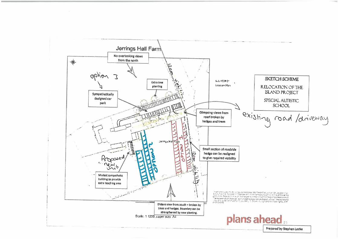
Related Documents