ELECTRONIC COPY - NOT FOR USE OUTSIDE THE AGENCY PAPER COPIES OF THIS ELECTRONIC DOCUMENT ARE UNCONTROLLED Geotechnical Considerations and Techniques for Widening Highway Earthworks Summary: This Advice Note describes a number of methods of widening highway earthworks using reinforced soil, soil nailing and soil improvement. Crown Copyright 1991 Price £1.00 © THE HIGHWAYS AGENCY HA 43/91 THE SCOTTISH OFFICE DEVELOPMENT DEPARTMENT THE WELSH OFFICE Y SWYDDFA GYMREIG THE DEPARTMENT OF THE ENVIRONMENT FOR NORTHERN IRELAND

Welcome message from author
This document is posted to help you gain knowledge. Please leave a comment to let me know what you think about it! Share it to your friends and learn new things together.
Transcript
ELECTRONIC COPY - NOT FOR USE OUTSIDE THE AGENCYPAPER COPIES OF THIS ELECTRONIC DOCUMENT ARE UNCONTROLLED
Geotechnical Considerations and
Techniques for Widening
Highway Earthworks
Summary: This Advice Note describes a number of methods of widening highwayearthworks using reinforced soil, soil nailing and soil improvement.
Crown Copyright 1991 Price £1.00©
THE HIGHWAYS AGENCY HA 43/91
THE SCOTTISH OFFICE DEVELOPMENT DEPARTMENT
THE WELSH OFFICE
Y SWYDDFA GYMREIG
THE DEPARTMENT OF THE ENVIRONMENT FOR
NORTHERN IRELAND
DESIGN MANUAL FOR ROADS AND BRIDGES
ELECTRONIC COPY - NOT FOR USE OUTSIDE THE AGENCY
February 1991 PAPER COPIES OF THIS ELECTRONIC DOCUMENT ARE UNCONTROLLED
VOLUME 4 GEOTECHNICS ANDDRAINAGE
SECTION 1 EARTHWORKS
HA 43/91
GEOTECHNICAL CONSIDERATIONSAND TECHNIQUES FOR WIDENINGHIGHWAY EARTHWORKS
Contents
Chapter
1. Introduction
2. Scope
3. Initial Considerations
4. Technical Approval (Structures) andGeotechnical Certification
5. Drainage
6. Widening Methods
7. Construction
8. Acknowledgements
9. References
10. Enquiries
Appendix 1
Volume 4 Section 1 Chapter 1HA 43/91 Introduction
ELECTRONIC COPY - NOT FOR USE OUTSIDE THE AGENCY
February 1991 PAPER COPIES OF THIS ELECTRONIC DOCUMENT ARE UNCONTROLLED 1/1
1. INTRODUCTION
1.1 The 1989 Government's White Paper 'Roads for Prosperity' (Ref 1) outlined plans for an Expanded RoadProgramme. As part of this Programme, it is envisaged that about 60 percent of the motorway network in England aswell as some trunk roads will need to be widened by the provision of additional lanes. Many of these roads are in urbanareas or adjacent to development which precludes the option of acquiring additional land without major public inquiries.Significant time delays would be incurred in such cases and new traffic lanes will therefore need to be provided withinthe existing highway boundary.
1.2 This presents particular problems where the existing carriageway is on embankment or in cutting. In thissituation it may be necessary to consider steepening the side slopes of existing earthworks. Potential methods include:
a. steepening the side slopes of embankments by using granular materials or soil stabilisation;
b. steepening the side slopes using soil reinforcement or soil nailing:
c. using full or part height earth retaining walls, such as embedded, gravity, gabion or crib walls or usingother structural solutions.
1.3 If the proposed design involves the use of any exposed concrete, steel or other materials, or if it is likely to bevisually intrusive, then the advice of the Department's Regional Landscape Architect or Horticultural Officer should besought at the earliest possible stage to advise on the environmental aspects of the proposed solution.
1.4 At the same time, consideration needs to be given to the fact that on slopes a significant incidence of shallowfailures has been reported (Ref 2) in ageing motorway earthworks, particularly those constructed in over-consolidatedmaterials. These are usually clays, which during their history have been subjected to greater vertical pressures than atpresent: common causes of overconsolidation are the erosion of overlying materials and the melting of ice masses.Slope steepening may well exacerbate these failures, if appropriate measures are not taken at the design stage.
1.5 This Advice Note describes a number of methods of widening existing earthworks using soil reinforcing, soilnailing and other forms of soil improvement: it also indicates other aspects which need to be considered.
1.6 For any particular scheme only some of the methods available may be appropriate. However, considerationshould be given to as wide a range of solutions as possible in order to ensure that the most appropriate technical andeconomic solution is adopted for each particular case. Some information on the comparative costs of reinstatementtechniques for embankment failures is given in Ref 3. Existing and proposed landscaping and land access will also needto be considered at an early stage.

Volume 4 Section 1 Chapter 2HA 43/91 Scope
ELECTRONIC COPY - NOT FOR USE OUTSIDE THE AGENCY
February 1991 PAPER COPIES OF THIS ELECTRONIC DOCUMENT ARE UNCONTROLLED 2/1
2. SCOPE
2.1 This Advice Note is issued for the guidance of engineers responsible for the design of the geotechnical andassociated aspects of widening highway earthworks, particularly motorway widening schemes. It describes some of thefactors which may influence slope stability and gives information on some of the methods available. it is to be notedthat it is not a design guide.
2.2 Sections 3, 4 and 5 of this Advice Note set out considerations which are generally applicable to the widening ofhighway earthworks. Techniques involving earthworks or soilstrengthening are then described in Section 6. Methods based on the use of retaining walls or other structural solutionsare generally more expensive, but in some cases will be unavoidable.This Advice Note does not cover such methods, but guidance may be obtained elsewhere: in particular TechnicalMemorandum BE 3/78 (Revised 1987) deals with reinforced and anchored earth retaining walls (Ref 4) andDepartmental Standard BD 30/87 deals with backfilled retaining walls (Ref 5). Other Departmental Standards andAdvice Notes should be used where appropriate.
Volume 4 Section 1 Chapter 3HA 43/91 Initial Considerations
ELECTRONIC COPY - NOT FOR USE OUTSIDE THE AGENCY
February 1991 PAPER COPIES OF THIS ELECTRONIC DOCUMENT ARE UNCONTROLLED 3/1
3. INITIAL CONSIDERATIONS
3.1 A number of sources of information exists on ground conditions and related geotechnical matters for themotorway and trunk road network. These may be of considerable benefit to designers undertaking widening schemeswhen they are preparing their 'Desk Study Report' and some details are given below.
3.2 Copies of the ground investigation reports for most of the motorway network and some trunk roads are held bythe appropriate Regional Offices of the Department, by Highways Engineering Division, by Ground EngineeringDivision at the Transport and Road Research Laboratory (TRRL) and by the British Geological Survey. Furtherinformation can be obtained from Highways Engineering Division .
3.3 TRRL published a major survey of the condition of motorway side slopes in Research Report 199 (Ref 2). Thecomputer database on which this report is based contains information on the condition of side slopes for over twenty percent of the motorway network in England and Wales. The database contains details of geology, geometry, drainage,slope condition, vegetation and age when surveyed. Further information on the database can be obtained from GroundEngineering Division at TRRL. In addition, highway maintenance authorities are required to report earthworks failuresto the Regional Offices (Ref 6): these reports should be consulted to highlight problems in a particular area.
3.4 The preliminary sources of information given above, together with additional information held by the RegionalOffices, including 'as built' drawings and other information on the site, should be consulted to obtain as muchgeotechnical detail as possible. An assessment of the implications of this should then be made to determine theimplications for the stability of existing earthworks and the consequences of widening them. The scope of anyadditional ground investigation should then be considered: this will need to be tailored to the methods likely to be usedfor widening. It may also be necessary to determine if the properties of the undisturbed soil and fill materials havechanged with time and loading conditions from those given in the preliminary sources of information.
3.5 On earthworks where widening is likely to be carried out in the future, such widening should be borne in mindwhen planning current or future maintenance, cabling or similar activities.
3.6 A decision tree representing the process of earthworks widening is shown in Fig 1. Some of the potentialproblems likely to be encountered are listed below: however, the list is not exhaustive.
3.7 Existing Earthworks Wide Enough
Where the existing earthworks are sufficiently wide to accommodate the additional lanes required, the following pointswill need to be considered.
a. Moving the edge of the carriageway closer to the shoulder of the embankment or the toe of the cuttingmay reduce the stability of the earthwork. In this situation, consideration should be given to the followingtechniques:
i. the provision of a combined debris catcher unit and surface water channel (Ref 7) at the toe ofcutting slopes;
ii. the provision of a large edge beam or verge wall at the back of the hardshoulder (Ref 8);
iii. the use of insitu soil reinforcing techniquessuch as soil nailing (See Section 6.4).
Chapter 3 Volume 4 Section 1Initial Considerations HA 43/91
ELECTRONIC COPY - NOT FOR USE OUTSIDE THE AGENCY
PAPER COPIES OF THIS ELECTRONIC DOCUMENT ARE UNCONTROLLED February 19913/2
b. The condition of the earthwork may be such as to giverise to concern for its stability because of the presence of slip surfaces, cracking, seepage planes or excessivesettlement. In this case, it may be necessary to carry outremedial works prior to or concurrent with the widening work.Possible techniques include the following:
i. soft spot replacement: the replacement of localsoft spots with granular materials or lime stabilisedmaterial (Ref 6);
ii. the use of geotextile or geogrid reinforced soilrepair techniques (Refs 3 and 9);
iii. rock ribs: the use of deep counterfort drains orgeotextile reinforced granular buttresses (Ref 3, 7 and10), or the use of slope drains (Section 6.5).
c. Particular attention to the problems in (b) will be required when the hardshoulder is to be used as arunning lane during construction work.
3.8 Existing Earthworks Not Wide Enough
Where the existing earthworks are not sufficiently wide to accommodate the additional lanes required, the followingpoints will need to be considered.
a. If the condition of the earthwork gives rise to concern for its stability, it is unlikely that widening willhelp stability unless repair or strengthening of the existing embankment or cutting is incorporated into thewideningprocess. Adding additional material to the top of an embankment or removing material from the toe of a cuttingwhich is already in poor condition will only exacerbate the situation.
b. Potential problems identified in the original site investigation such as faults, deep seated slips, naturalor man-made cavities, made ground etc need to be overcome using similar technique to those used in theoriginal construction.
c. The presence of organic layers, soft ground or other difficult ground conditions in the foundation of theexisting embankment or in the base of the existing cutting will need assessment. Any special engineeringmeasures taken in the original design to overcome these problems need to be incorporated in the wideningprocess. These might include soil improvement or reinforcement, additional drainage to improve consolidationand stability, or other methods of reducing settlement and increasing stability.
3.9 When assessing the methods of widening existing embankments, consideration should also be given to thefollowing aspects.
a. The need to bench in the new works to the existing embankment in such a manner that the contactbetween them does not generate a plane of weakness.
b. The effects of construction and compaction of new works on the stability of the existing embankment.
c. The methods of dealing with the likely differential settlements and associated shear forces which mayoccur as the new works consolidate at a higher rate than any residual consolidation in the original embankment.The effects of differential settlement will also need to be carefully considered in the design of the transitionbetween the existing and the new pavement.
Volume 4 Section 1 Chapter 3HA 43/91 Initial Considerations
ELECTRONIC COPY - NOT FOR USE OUTSIDE THE AGENCY
February 1991 PAPER COPIES OF THIS ELECTRONIC DOCUMENT ARE UNCONTROLLED 3/3
d. Earthworks incorporating some types of reinforcement and soil nailing may undergo significant lateralexpansion during and immediately after construction. This should be allowed for before constructing thepavement and drainage system.
3.10 When assessing the methods of widening existing cuttings, important aspects will include the following.
a. The influence of rock discontinuities and their properties on the stability of steepened slopes. Furtherinformation is contained in Refs 11 and 12.
b. The possible need to incorporate current requirements for sight lines when widening older motorwaysand trunk roads (Ref 13).
3.11 For both cuttings and embankments, the following aspects should not be overlooked.
a. The potential effects of construction on sensitive adjacent structures and on other adjacent featuressuch as canals, railways, rivers etc.
b. The relative volumes of cut and fill likely to be generated by the widening methods adopted, althoughthis may be difficult to balance in on-line widening schemes and may require costly double handling ofmaterial.
c. The cost of traffic delays during road widening will usually be substantial and will be a major factor inthe choice of method. Further details are given in Ref 14.
d. Where geotextiles or related products, or soil nails qre used to strengthen the earthwork, care should betaken to ensure that they are not damaged by the subsequent installation of safety fence posts, sign and lightingcolumns, cables and trenches, or by subsequent planting ormaintenance work. The potential conflict between edge of pavement drains, which extend below the undersideof capping, and the upper layers of reinforcement or nails will also need to be considered.
e. The need to achieve adequate foundation support for verge safety fences to ensure their fitness forpurpose.
Volume 4 Section 1 Chapter 4HA 43/91 Technical Approval (Structures) and Geotechnical Certification
'Polymeric’ is used here as a generic term to describe geotextiles, geogrids and related products made from1
polyethylene, polypropylene, polyester or other polymers.
ELECTRONIC COPY - NOT FOR USE OUTSIDE THE AGENCY
February 1991 PAPER COPIES OF THIS ELECTRONIC DOCUMENT ARE UNCONTROLLED 4/1
4. TECHNICAL APPROVAL (STRUCTURES)AND GEOTECHNICAL CERTIFICATION
4.1 Although not covered by this Advice Note, retaining walls with a design retained height in excess of 1.5mrequire technical approval in accordance with Departmental Standard BD 2/89 Part 1 (Ref 15). Reinforced earthstructures having a hard facing, such as those defined in Technical Memorandum BE 3/78 (Ref 4), will require technicalapproval.
4.2 Reinforced soil has a soft facing of soil or granular material which may, or may not, be contained by a surfacelayer of geotextile, geogrid or related product. As earthworks, they will normally be topsoiled and sown or planted. Thiswill also normally be the case for slopes where soil nailing is used.
4.3 Gabion and crib walls are earth retaining structures and technical approval is required if they have a designretained height in excess of 1.5m. If they are less than this height, they will require geotechnical certification.
4.4 Technical approval procedures shall be followed for strengthened embankments when the angle of the slopeface to the horizontal is 70 degrees or greater and the design retained height is greater than 1.5m. Where the angle of theslope face to the horizontal is 45 degrees or less, geotechnical certification will be required. For strengthenedembankments between these limits, the advice of the Overseeing Department should be sought.
4.5 In such cases, the decision on whether technical approval or geotechnical certification is the most appropriatecourse of action will depend on the consequences of failure of the strengthened e embankment and the difficulty ofrepairing it.
4.6 Earthworks incorporating reinforced soil or soil nailing require a design life to be ascribed to them so that thecreep and durability properties of polymeric materials and the corrosion properties of metallic materials can be1
assessed. For reinforced earth retaining walls designed in accordance with BE 3/78 (Ref 4), the design life is 120 years:where geotechnical certification is used, the design life shall be not less than 60 years.
4.7 Until such time as detailed design methods and performance criteria are issued by the Department, theContractor will need to supply evidence to show that proprietary materials to be used to strengthen earthworks haveproperties which ensure that they are fit for the purpose intended and that they will retain these properties for theprescribed design life. This information will also need to cover site damage to the materials during installation.
4.8 In the longer term, it is the intention of the Department that proprietary materials for use in reinforced soil andsoil nailing will require a Roads and Bridges Certificate issued by the British Board of Agrement or an equivalent body.

Volume 4 Section 1 Chapter 5HA 43/91 Drainage
ELECTRONIC COPY - NOT FOR USE OUTSIDE THE AGENCY
February 1991 PAPER COPIES OF THIS ELECTRONIC DOCUMENT ARE UNCONTROLLED 5/1
5. DRAINAGE
5.1 It may be possible in some circumstances to incorporate the existing drainage of the sub-base and existingdrains at the toe of the embankment, or at the top of cuttings, into the new design.
5.2 In many cases, however, it is likely that the existing drainage will need to be replaced. This is particularly trueat the edge of the pavement, where the use of combined filter and surface water drains is now considered to befundamentally undesirable. Advice on edge of pavement details is given in a Departmental Advice Note (Ref 16) andstandard details are shown in Highway Construction Details (Ref 17).
5.3 When the edge of pavement drain is to be replaced, it is important to ensure that the existing drain does not actas a reservoir for water to subsequently enter the sub-base or the subgrade. This can be achieved by either removing theoriginal drain completely or introducing positive drainage from the bottom of the original drain to the new drainagesystem. It will also be necessary to ensure that the types and thicknesses of materials used for capping and sub-baseconstruction are such that they do not impede the drainage of the existing sub-base and/or capping and vice versa.
5.4 Drainage must be maintained at all times and the possible consequences of prolonged heavy rainfall or rapidthaw during reconstruction must be allowed for. The specification for sub-base and capping materials will also need totake account of this requirement.
5.5 Temporary drainage measures may therefore be required during the works as well as temporary connections toensure that the adjacent permanent drainage continues to function.
5.6 In view of the particular susceptibility to chloride attack of metallic elements such as reinforcements or nails,every effort should be made to ensure that chloride contaminated surface run-off water and groundwater are not allowedto percolate into areas where these are used. Further information is given in Section 13.2 of Departmental Standard BD12/88 (Ref 18).
Volume 4 Section 1 Chapter 6HA 43/91 Widening Methods
ELECTRONIC COPY - NOT FOR USE OUTSIDE THE AGENCY
February 1991 PAPER COPIES OF THIS ELECTRONIC DOCUMENT ARE UNCONTROLLED 6/1
6. WIDENING METHODS
6.1 Design Considerations
6.1.1 When considering the adoption of any of the techniques described in this Advice Note, the problems ofshort term as well as long term stability will need to be addressed. In most cases, it will therefore be necessaryto consider the undrained situation as well as the fully drained condition.
6.1.2 In order to obtain the most economic solution and efficient construction sequence, the number ofwidening options finally adopted should be kept to a minimum within any one contract.
6.2 Conventional Solutions
6.2.1 The simplest solution to widening an earthwork is to use the original slope angle and construct withinthe existing highway boundary: this does, of course, require sufficient space to be available. However, there is anumber of caveats to be placed on such a method.
a. If the existing earthwork is showing signs of instability or if weathering or softening of the slopes isoccurring already or is likely to occur in the future, it may be prudent to include a strengtheningtechnique in the new construction.
b. Benching into the existing embankment is required, and it is important to ensure that potentialplanes of weakness are removed by excavating back into sound material. A stability analysis must becarried out to check that there is an acceptable factor of safety against deep seated as well as shallowerfailures.
6.2.2 An alternative solution is to construct the new shoulders of an embankment using granular materials orchemically stabilised cohesive materials, eg lime stabilisation, possibly using a steeper slope angle. In additionto the provisos in Section 6.2.1, the following should also be taken into account.
a. Using granular materials, which are relatively permeable, may allow surface water to percolatedown to cohesive materials in the existing embankment and cause long-term softening to occur atdepth.
b. It must be demonstrated that chemically stabilised materials are likely to retain sufficient strength inthe long-term. Further information is given in Ref 19, which deals with the strength of lime stabilisedclays.
6.2.3 In some cases, it may be possible to reconstruct embankments with steeper side slopes using on-sitematerials and to steepen existing cutting slopes, in both instances without compromising stability. In thesecases, the factors discussed in Section 6.2.1 are likely to be even more important.
6.3 Reinforced Soil
6.3.1 In this method, horizontal layers of reinforcing elements are incorporated between layers of compactedfill material to improve the stability of the resulting soil mass. Many types of reinforcing materials have beenused including metallic strips, geotextiles and geogrids. Reinforcements have been incorporated successfully ina range of soils from granular through to heavily over-consolidated clays, by adopting an appropriatecombination of reinforcement and soil types for a particular application.
6.3.2 Because the technique involves incremental construction from the bottom upwards it is moreappropriate to the construction and repair of embankments (Ref 3). However, the technique may be used for therepair of cutting failures when appropriate (Ref 9).
Chapter 6 Volume 4 Section 1Widening Methods HA 43/91
ELECTRONIC COPY - NOT FOR USE OUTSIDE THE AGENCY
PAPER COPIES OF THIS ELECTRONIC DOCUMENT ARE UNCONTROLLED February 19916/2
6.3.3 In embankments where the soils may have a wide range of mechanical and chemical properties, the useof geotextiles, geogrids and related products is more common than the use of metallic reinforcements. Twocommon arrangements of geotextile reinforcements have been used. The first involves wrapping thereinforcement around the slope face and embedding the upper end as shown in Fig 2: this technique isappropriate in steeper slopes or where the soil has relatively poor long-term strength. The second method,shown in Fig 3 is to truncate the reinforcement at the slope face: although this method is easier to construct, itmay allow material to slough from the slope face in the longer term.
6.3.4 All polymeric materials are susceptible to creep and to the associated problems of load relaxation,stress rupture and damage. These phenomena need to be carefully evaluated in design. Methods of achievingthis have been reviewed in the literature (Refs 20, 21 and 22).
6.3.5 In a reinforced soil structure, consideration needs to be given to both external and internal stability.Analyses for external stability cover translational, rotational and bearing failure of the reinforced soil mass,whereas internal stability covers the soil-reinforcement bond, pull-out of the reinforcement and rupture.
6.3.6 The design of reinforced slopes is normally based on limit equilibrium analysis. This form of analysisdoes not take into account directly the stress-strain behaviour of the soil or of the reinforcement: however, limitequilibrium methods have been used extensively and offer a fairly straightforward method of design. Analysesare usually based on a two-part wedge mechanism (Refs 23 and 24), but circular methods have also been used(Ref 25).
6.3.7 in using this technique to widen existing embankments or to repair existing cuttings, particularattention must be given to both overall settlements and differential settlements within the reinforced soil mass.The effect of these settlements on the loads and strains induced in the reinforcements will need to be consideredcarefully in design. This subject has been covered in a review of the use of reinforced soil in areas of miningsubsidence (Ref 26).
6.3.8 In addition, many of the potential problems discussed in Sections 3 and 6.2 will also be relevant to thedesign of reinforced soil for this application. In practice, it is likely that for most applications, the length ofreinforcement will need to be such that it extends well beyond the slope face of the existing embankment,which will need to be cut back. This may result in an excavation of such depth that a lane closure is required,but it does have the following advantages:
a. it will reduce the change of a failure occurring in the zone of contact between the existing slope faceand the new construction;
b. it will also help to smooth out differential settlements between the old and the new construction.
6.3.9 In simple applications, such as low height and relatively shallow slopes, the design of reinforced soilstructures will normally be relatively straightforward. However, the complexity of design and the likelyconsequences of failure will increase with increasing height and slope angle. Reinforced soil is still beingdeveloped andt in all but the simplest applications, it may be prudent to obtain specialist geotechnical advicebefore this solution is adopted. In the first instance, enquiries should be directed to the appropriate RegionalOffice.
Volume 4 Section 1 Chapter 6HA 43/91 Widening Methods
ELECTRONIC COPY - NOT FOR USE OUTSIDE THE AGENCY
February 1991 PAPER COPIES OF THIS ELECTRONIC DOCUMENT ARE UNCONTROLLED 6/3
6.4 Soil Nailing
6.4.1 The technique of reinforced soil is generally accepted as applying to the improvement of soil byincorporating reinforcement into the fill as construction takes place. In contrast, soil nailing is usually appliedto natural or man-made slopes and enhances stability by the installation of reinforcements directly into theground after the slope has been formed. It is therefore more likely to be used to prevent the failure of cuttingslopes or to increase the stability of such slopes when they need to be steepened. However, it can also be usedto improve the stability of existing embankment slopes, but in general would not be appropriate for use in theconstruction of new embankments.
6.4.2 The other major differences between soil nailing and soil reinforcing are as follows.
a. In soil reinforcing, backfill materials with appropriate strength and corrosion properties can be used,whereas soil nailing has to cope with what already exists.
b. In reinforced soil, tensions generally develop as construction progresses, thus allowing thereinforcing elements to participate in increasing stability. In soil nailing, some general groundmovements will be necessary after installation of the system and before tensions develop in theelements.
c. Reinforced soil is constructed from the bottom upwards whereas soil nailing is normally constructedfrom the top downwards.
6.4.3 Two typical schematic layouts of steepened slopes incorporating soil nailing are shown in Figs 4 and 5.The reinforcements most commonly used are round metal bars or tubes with typical diameters of 20 to 50mmwhich are installed either by driving or inserting into pre-formed or pre-drilled holes of 80-120mm diameter.Cement grout may then be pumped into the hole at relatively low pressures to form a bond between thereinforcement and the surrounding ground. The nail is then connected by a threaded arrangement to a bearingplate at the surface. The size of this plate will depend on the load in the nail and the soil properties. For slopeangles greater than about 60 degrees, the whole of the slope face may subsequently need to be covered by someform of hard facing. In all cases, the Department's Regional Landscape Architect or Horticultural Officershould be consulted at the earliest possible stage to advise on the suitability, from an environmental aspect, ofthe proposed facing.
6.4.4 In addition to metal rods and tubes, a number of other reinforcements have been suggested. Theseinclude expanded anchors in which the buried end of the anchor is expanded mechanically, pneumatically,hydraulically, or by controlled explosion. Wedge pile anchors which are expanded along their entire lengthhave also been used, as have anchor shoes attached to lengths of wire rope. In this latter type, a pivotarrangement compels the anchor shoe to rotate into a fully resistant position under load (Ref 3), but because ofthe pivot arrangement and wire rope, the anchor cannot develop resistance through shear. In addition,significant relative movement is required to develop the full pull-out resistance of the anchor.
6.4.5 Soil nailing has been very little used in the United Kingdom. However, it has had considerable use inWest Germany and France, where it is highly regarded as a convenient and cost-effective technique. A reviewof its use is given in Ref 27, and a review of the subject for typical road applications in the United Kingdom isgiven in Ref 28.
6.4.6 Design methods for soil nailing are similar in concept to those used for reinforced soil and include thesame checks for external and internal stability. Details of a limit equilibrium analysis using a two-part wedgeare given in Ref 28, and an analysis using a parabolic failure surface is described in Ref 29. A method ofanalysis which considers the influence of bending and deformation has been described in Ref 30. However,full-scale tests (Ref 31) have indicated that the shearing resistance generated by the nails is small: this is atvariance with the design method given in Ref 30. Further research is currently underway to resolve this point.

Chapter 6 Volume 4 Section 1Widening Methods HA 43/91
ELECTRONIC COPY - NOT FOR USE OUTSIDE THE AGENCY
PAPER COPIES OF THIS ELECTRONIC DOCUMENT ARE UNCONTROLLED February 19916/4
6.4.7 Although most of the applications of soil nailing are likely to be concerned with the steepening ofexisting slope angles or with increasing the stability of slopes considered to be at risk, another potentialapplication is to enhance the load carrying capacity of existing earthworks. This could be particularly usefulwhere the influence of surface loads applied close to the edge of an embankment might cause a large scalebearing failure of the shoulder. This application has been considered in Ref 28.
6.4.8 Many of the potential problems to be considered in the design of soil nailing are similar to thosealready described in Sections 3 and 6.2. In addition, the durability of the nails will need to be carefullyassessed, as will the potential benefits of any protective coating envisaged. Soil corrosivity assessment (Ref 32)and the use of protective coatings in soil structures (Ref 33) have both been reviewed by TRRL.
6.4.9 Although soil nailing has had little application in the United Kingdom, it appears to offer the potentialfor significant savings over other techniques. The design methods are still in the development stage, as are theconstruction techniques. However, experience in Europe suggests that the design and construction techniquesare adequate to allow soil nailing to be implemented safely. In view of the limited experience with thistechnique, it is important that specialist geotechnical advice should be obtained before the solution is adopted.In the first instance, enquiries should be directed to the appropriate Regional Office.
6.5 Slope Drainage
6.5.1 Slope drainage is widely used in highway works to reduce pore water pressures and thereby improvestability, both in new construction and in existing cutting slopes. Counterfort drainage, in which strength is alsoprovided by the use of rock fill, is less widely used. As with all forms of sub-surface drainage, care must betaken to ensure that the granular or geotextile filter is correctly designed for the soil in contact with it.Consideration must also be given to the ease of subsequent inspection and maintenance.
6.5.2 When considering slope drainage, an adequate ground investigation is required to ensure the following.
a. The actual or potential failure mechanisms are correctly identified and that the stability will beadequately improved by drainage.
b. The soil is reasonably isotropic with respect to permeability, in which case design charts of the typegiven in Ref 34 may be used. If the soil is markedly anisotropic (eg some alluvial deposits), or containsseepage planes, appropriate charts are not available and the dimensions of the drainage system must becalculated (Ref 34).
6.5.3 Possible applications of slope drainage are:
a. deep drains to improve the short or long term stability of cutting slopes against deep-seated failure;
b. shallow, closely spaced drains to reduce the incidence of the type of shallow, planar slips identifiedin Section 3.3;
c. bored horizontal drains are little used in the UK, but may be an appropriate solution in large cuttingswith well defined seepage zones.
6.5.4 In principle, slope drainage is also applicable to embankments. However, as mentioned in Section6.2.2(a), there is a risk that this will allow water to percolate into the drier materials at depth within theembankment. In addition, compacted clay fills are not fissured like natural clays and are therefore likely to beless permeable. It may therefore take many years for them to reach equilibrium with the installed drainage.
Volume 4 Section 1 Chapter 7HA 43/91 Construction
ELECTRONIC COPY - NOT FOR USE OUTSIDE THE AGENCY
February 1991 PAPER COPIES OF THIS ELECTRONIC DOCUMENT ARE UNCONTROLLED 7/1
7. CONSTRUCTION
7.1 Some details of construction have been given in earlier Sections of this Advice Note and further details aregiven in the References cited. However, particular emphasis should be placed on the following aspects.
7.2 There are three important rules for working on earthwork slopes.
a. DO NOT remove material from the toe of the slope except under controlled conditions which maintainstability.
b. DO NOT stockpile material at the top of the slope.
c. DO NOT allow water to enter the slope and check that the existing drainage system is functioning correctly.
7.3 In many situations involving excavation into an existing slope, it will be necessary to work in short sectionssuch that the material left in place on either side of the excavation provides arching support. It is also important to keepthe time for which the excavation is unsupported to a minimum, especially with cohesive soils where the dissipation ofnegative pore water pressures may cause instability.
7.4 Many side slopes on motorway and trunk road earthworks are already showing signs of distress, on others aheavily vegetated and desiccated crust may be disguising softened material at a lower level. All construction techniquescause some disturbance, which will need to be kept to a minimum by using appropriate types of plant located in theappropriate place.
7.5 Where trees or shrubs exist on the embankment or cutting slope, the Department's Regional LandscapeArchitect or Horticultural Officer should be consulted to establish if any of the vegetation can be retained forenvironmental reasons, and if so what protection measures need to be adopted to safeguard such retention.
7.6 There is some evidence to suggest (Ref 2) that good compaction of fill materials in embankment side slopesincreases the stability of the slope in the longer term. Good compaction control is therefore of primary importance:Table 6/4 of the Specification for Highway Works (Ref 35) shows that it is possible to achieve as high a level ofcompaction using a larger number of passes and smaller compacted layer thicknesses with lightweight compaction plantas it is with heavy equipment. The former is to be preferred where stability is critical or space is at a premium.
7.7 The sequence of site operations, the handling of materials and the location of plant accesses are essentialmatters which must be catered for as part of the design: to overlook them may lead to instability, create dangeroushazards and increase costs, particularly on long narrow worksites.
7.8 DTp requirements for working spaces and safety zones must be observed: safety zones are covered in theTraffic Signs Manual, Chapter 8 (Ref 36). The Note for Guidance on Safe Working on Trunk Roads and Motorways(Ref 37) should also be consulted.
7.9 When using any of the techniques described in Section 6, the finished side slopes should, wherever possible, betopsoiled, grassed and seeded in accordance with SHW Clause 618. On steeper slopes, it may be necessary toincorporate measures to reduce the incidence of soil erosion. Geotextiles and related products, except those usedspecifically to reduce soil erosion, must not be left exposed to sunlight. Further information is also contained in aCIRIA publication on the use of vegetation in civil engineering (Ref 38).
Volume 4 Section 1 Chapter 8HA 43/91 Acknowledgement
ELECTRONIC COPY - NOT FOR USE OUTSIDE THE AGENCY
February 1991 PAPER COPIES OF THIS ELECTRONIC DOCUMENT ARE UNCONTROLLED 8/1
8. ACKNOWLEDGEMENT
8.1 Much of the work on which this Advice Note is based was carried out by the Ground Engineering Division andStructural Analysis Unit of the Transport and Road Research Laboratory for the Highways Engineering Division of theDepartment of Transport.

Volume 4 Section 1 Chapter 9HA 43/91 References
ELECTRONIC COPY - NOT FOR USE OUTSIDE THE AGENCY
February 1991 PAPER COPIES OF THIS ELECTRONIC DOCUMENT ARE UNCONTROLLED 9/1
9. REFERENCES
1. DEPARTMENT OF TRANSPORT (1989). Roads for Prosperity. White Paper (Cm 693).
2. PERRY J (1989). A survey of slope condition on motorway earthworks in England and Wales. TRRLResearch Report 199.
3. JOHNSON P E (1985). Maintenance and repair of highway embankments: studies of seven methods oftreatment. TRRL Research Report 30.
4. DEPARTMENT OF TRANSPORT (1978). Reinforced and anchored earth retaining walls and bridgeabutments for embankments. Technical Memorandum BE 3/78 (Revised 1987).
5. DEPARTMENT OF TRANSPORT (1987). Backfilled retaining walls and bridge abutments.Departmental Standard BD 30/87.
6. DEPARTMENT OF TRANSPORT (1983). Maintenance of highway earthworks. DepartmentalAdvice Note HA 26/83.
7. MILNES J T, AMOS J H AND REES A (1989). Fast track on the M62 slow lane. Highways andTransportation, September, pp 13-19.
8. STAPLETON G and WHITFIELD A (1990). A decade of M5 widening. Highways andTransportation, September, pp 6-12.
9. MURRAY R T, WRIGHTMAN J AND BURT A (1982). Use of fabric reinforcement for reinstatingunstable slopes. TRRL Supplementary Report 751.
10. GREENWOOD J R, HOLT D A and HERRICK G W (1985). Shallow slips in highway embankmentsconstructed of overconsolidated clay. Proc Symp on Failures in Earthworks, London, pp 79-93.
11. HOEK E and BRAY J W (1981). Rock slope engineering. 3rd Edition (Institution of Mining andMetallurgy).
12. MATHESON G D (1983). Rock slope stability assessment in preliminary site investigation - graphicalmethods. TRRL Laboratory Report 1039.
13. DEPARTMENT OF TRANSPORT (1981). Highway link design. Departmental Standard TD 9/81.
14. DEPARTMENT OF TRANSPORT (1987). Quadro 2 manual. Assessment Policy and MethodsDivision.
15. DEPARTMENT OF TRANSPORT (1989). Technical approval of highway structures on motorwaysand other trunk roads. Departmental Standard BD 2/89 Part 1.
16. DEPARTMENT OF TRANSPORT (1991). Edge of pavement details. Departmental Advice Note HA39/89.
17. DEPARTMENT OF TRANSPORT (1987). Highway construction details.
Chapter 9 Volume 4 Section 1References HA 43/91
ELECTRONIC COPY - NOT FOR USE OUTSIDE THE AGENCY
PAPER COPIES OF THIS ELECTRONIC DOCUMENT ARE UNCONTROLLED February 19919/2
18. DEPARTMENT OF TRANSPORT (1990). Corrugated steel buried structures. Departmental StandardBD 12/88.
19. ROGERS C D F and BRUCE C J (1990). The strength of lime stabilised British clays. LimeStabilisation '90, pp 57-72.
20. ANDREWS K Z, MCGOWN A and MURRAY R T (1986). The loadstrain-time-temperaturebehaviour of geotextiles and geogrids. Proc 3rd Int Conf on Geotextiles, Vienna, Volume 3, pp 707-712.
21. BUSH D I (1988). Evaluation of the effects of construction activities on the physical properties ofpolymeric soil reinforcing elements. Proc Int Geotech Symp on Theory and Practice of Earth Reinforcement,Kyushu, pp 63-68.
22. MURRAY R T and MCGOWN A (1987). Geotextile test procedures: background and sustainedloading. TRRL Application Guide 5.
23. JEWELL R A, PAINE N and WOODS R I (1984). Design methods for steep reinforced embankments.Proc Conf Polymer Grid Reinforcement, London, pp 70-81.
24. MURRAY R T (1980). Fabric reinforced earth walls: development of design equations. GroundEngineering, October, pp 29-38.
25. JONES C J F P (1985). Earth reinforcement and soil structures. (Butterworths).
26. MURRAY R T, JONES C J F P and SMITH R J (1989). Reinforced soil in areas of mining subsidence.Proc 12th Int Conf on Soil Mechanics and Foundation Engineering, Rio de Janeiro, Volume 2, pp 1289-1295.
27. BRUCE D A and JEWEL R A (1986-7). Soil nailing: application and practice - parts 1 and 2. GroundEngineering, November 1986, January 1987.
28. MURRAY R T (1989). A review of soil nailing. TRRL Structural Analysis Unit, Working Paper No1/90.
29. BANG S, SHEN C K and ROMSTAD K M (1980). Analysis of an earth reinforcing system for deepexcavations. Transportation Research Record 749, Washington.
30. DELMAS P, BERCHE J C, CARTIER G and ABDELHEDI A (1988). A new procedure for use indimensioning the nails of slopes: PROSPER program. Bull Liaison LCPC; Volume 141, pp 57-66.
31. GASSLER G (1988). Soil nailing - theoretical basis and practical design. Proc Int Geotech Symp onTheory and Practice of Earth Reinforcement, Kyushu, pp 283-288.
32. EYRE D and LEWIS D A (1987). Soil corrosivity assessment. TRRL Contractor Report 54.
33. ALLEN M D, HUDSON D R J and MITCHELL J (1988). Review of protective coatings for reinforcedearth and culvert structures. TRRL Contractor Report 103.
34. HUTCHINSON J N (1977). Assessment of the effectiveness of corrective measures in relation togeological conditions and types of slope movement. Bull Int Assoc of Eng Geol, No 16, pp 131-155.
35. DEPARTMENT OF TRANSPORT (1986). Specification for highway works, 6th Edition.

Volume 4 Section 1 Chapter 9HA 43/91 References
ELECTRONIC COPY - NOT FOR USE OUTSIDE THE AGENCY
February 1991 PAPER COPIES OF THIS ELECTRONIC DOCUMENT ARE UNCONTROLLED 9/3
36. DEPARTMENT OF TRANSPORT (1990). Traffic signs manual.
37. DEPARTMENT OF TRANSPORT/COUNTY SURVEYORS SOCIETY (1980). Joint reportproviding notes for guidance in relation to the implementation of the Health and Safety at Work Act 1974 so faras they affect personnel who are required to undertake work on motorways and trunk roads. October 1980.
38. COPPIN N J and RICHARDS I G (1990). Use of vegetation in civil engineering. (Butterworths andCIRIA).

Volume 4 Section 1 Chapter 10HA 43/91 Enquiries
ELECTRONIC COPY - NOT FOR USE OUTSIDE THE AGENCY
February 1991 PAPER COPIES OF THIS ELECTRONIC DOCUMENT ARE UNCONTROLLED 10/1
10. ENQUIRIES
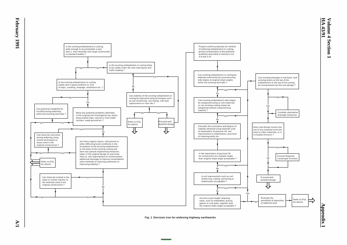
Can stability of the existing embankment orcutting be improved using techniques such as soil reinforcing, soil nail ing, soft spotreplacement or rock ribs ?
No
Prepare outline proposals for methodof widening embankment or cuttinggiving consideration to the potential problems described in Sections 3.8,3.9 and 3.10
No
Yes
No
Yes
Yes
No
Yes
Yes
No
No
No Yes
Yes
No
No Yes
No
Yes
No
Yes
Yes
No
No
Yes
No
Yes
Can existing embankment or cutting bewidened sufficiently by reconstructingside slopes at original slope angleswithin the existing land take ?
Can existing embankment side slopesbe steepened using on site materialsor can existing cutting slopes besteepened without compromisingstability ?
Consider the economics and degree ofstability obtained using methods suchas importation of granular fi l l , soilimprovement or stabil isation, provisionof retaining walls etc.
Is the importation of granular fi l lfor construction at a steeper anglethan original slope angle acceptable ?
Is soil improvement such as soilreinforcing, nailing, anchoring orstabilisation acceptable ?
Are full or part height retainingwalls, such as embedded, gravity,gabion or crib walls, together withthe original slope angle acceptable ?
Can existing drainage of sub base, andexisting drains at the toe of the embankment or the top of the cuttingbe incorporated into the new design ?
Consider alternativedrainage measures
Does new design involve theuse of any exposed concrete,steel or other materials, or isit visually intrusive ?
Consult RegionalLandscape Architect
Proceed withdetailed design
Evaluate thepossibil ity of aquisitionof addional land
Refer to DTp.for advice
Is the existing embankment or cuttingwide enough to accommodate a newlane 1, hard shoulder and verge constructedto standard widths ?
Is the existing embankment or cuttingstable and in good condition ie. freeof slips, cracking, seepage, settlement etc. ?
Is the existing embankment or cutting likelyto be stable under the new road layout andtraffic loading ?
Can potential instability berectified during wideningwithin the existing land take ?
Can these be overcomeduring widening usingsimilar techniques tothose used in theoriginal construction ?
Were any potential problems identif iedin the original site investigation eg. faults,deep seated slips, natural or man-madecavities, made ground etc ?
Refer to DTp.for advice
Are there organic layers, soft ground orother difficult ground conditions in thefoundation of the existing embankmentor the base of the existing cutting andwere any special engineering measurestaken in the original design to overcomethem ie. soil improvement or reinforcementadditional drainage to improve consolidationother methods of reducing settlement or improving stabil ity ?
Can these be treated in thesame or similar manner tothe methods used in theoriginal construction ?
Refer to DTp.for advice
Fig. 1 Decision tree for widening highway earthworks
Proceed withdetailed design
YesNo
No Yes
Yes
Volum
e 4 Section 1
HA
43/91A
ppendix 1
ELE
CT
RO
NIC
CO
PY
- NO
T F
OR
US
E O
UT
SID
E T
HE
AG
EN
CY
February 1991
PA
PE
R C
OP
IES
OF
TH
IS E
LEC
TR
ON
IC D
OC
UM
EN
T A
RE
UN
CO
NT
RO
LLED
A/1

Fig. 4 Soil nailing with a uniform slope angle
Fig. 5 Soil nailing with a terraced face
Fig. 3 Reinforced soil with reinforcement truncated at slope face
Fig. 2 Reinforced soil with wrap round face detail
Volume 4 Section 1Appendix 1 HA 43/91
ELECTRONIC COPY - NOT FOR USE OUTSIDE THE AGENCY
PAPER COPIES OF THIS ELECTRONIC DOCUMENT ARE UNCONTROLLED February 1991A/2
Related Documents