Geotech nica I E ng i neeri ng - A Historical Perspective 1.1 Ftlr enginccring purptlscs. sorl is clelincd as the uncemenled aggrcgate ol mineral grains and clccayed .rgirnic mattcr (solicl particlcs) with liquid u'ni gasrn rhc empty spaces bclwcen thc solid particlcs. Soil rs usedas a construction nraterial in vari.us civil cnsinccring proiccts'arrd it supports structuralfirunclations. 'l hus, civil cngi- ttccrs nrust studythc propcrtics ol soil. suchas its origin,grain-sizc clistribution, abil- ity to clrainwatcr' ctlmprcssibility. shcar strcngth.ancl loacl-bcaring capaci Iy.Sril rtreclturtiL"t is thc branchol scicncc thal clcals with thc stucly of the physical prope r- ties ol'soil ancl thc be havior tll'soilmASScs sul-l.icctcd to various typcsol'forccs. S'rl/s cttginccring is thc appli.cation ol'thc principlcs ol'soil rrcchanic.s te practical prob- lcnrs' (icr'rlct'hnit'ul cnginccring is the subclisciplinc ol'civil cnginccring that involves nitturaln.ratcrials firund closcto the surlacc ol thc earth. It inclucles ttc application tll'thc principles ol'stlil mcchanics ancl rock mcchanics to the clesign of f oundati.ns, rctaining structurcs. ar-rcl earth structurcs. Geotechnical Engineering prior to the Igth century fhc rccord tll'a pcrson'.s first uscol'soil as a construction natcrial is lost in antiquity. In true cnginceringternls. thc unclcrstancling ol'geotechnical engineering as it is kn.w'r today beea. c.rly in the lgtl'ccntury l.stempton, l9t3-5). Foryears the art of gcotcchnical cnginccring was based on only past cxpcricnccs through a succession ol experirncntation without any rcal scicnlific characier. Bascdon those expcrimen- tations, many structures were built - sonte of which have crumbled. while others are still standing. Recorcled historytclls us that ancicnt civilizations flourished alongthe banks of rivers, suchasthe Nilc (Fgypt). thc Tigrisancr Euphrates (Mes.potamra), the Huang Ho (YellowRiver. china), and the Indus(Inclia). Dykesaatingbackto about2000 s.c. wcre built in the basin of the Indus to protect the tow' of il4ohenjo Dara (in what bccamePakisran aftcr1947).Duringrhochanclynasryinchina(1l2be.c.to249e.c.) many dykes wcre built for irrigation purposes. There is no evidencethat measures were taken to stabilizethe foundations or check erosion caused by floods (Kerisel.

Welcome message from author
This document is posted to help you gain knowledge. Please leave a comment to let me know what you think about it! Share it to your friends and learn new things together.
Transcript
Geotech n ica I E n g i neeri n g -A Historical Perspective
1 . 1
Ft l r enginccr ing purpt lscs. sor l is c le l incd as the uncemenled aggrcgate o l mineralgra ins and c lccayed . rg i rn ic mat tcr (so l ic l par t ic lcs) wi th l iqu id u 'n i gas rn rhc emptyspaces bc lwcen thc sol id par t ic lcs. Soi l rs used as a construct ion nrater ia l in var i .usc iv i l cns inccr ing pro iccts ' arrd i t supports s t ructura l f i runclat ions. ' l
hus, c iv i l cngi -t tccrs nrust s tudy thc propcr t ics o l so i l . such as i ts or ig in, gra in-s izc c l is t r ibut ion, abi l -i ty to c l ra in watcr ' c t lmprcssib i l i ty . shcar s t rcngth. ancl loacl -bcar ing capaci Iy . Sr i lr t rec l tur t iL" t is thc branch o l sc icncc thal c lca ls wi th thc stuc ly of the physical prope r -t ies o l 'so i l ancl thc be havior t l l 'so i l mASScs sul - l . icctcd to var ious typcs o l ' forccs. S ' r l /sct tg inccr ing is thc appl i .cat ion o l ' thc pr inc ip lcs o l 'so i l r rcchanic.s te pract ica l prob-lcnrs' (icr'r lct 'hnit 'ul cnginccring is the subclisciplinc ol 'civil cnginccring that involvesni t tura l n. ratcr ia ls f i rund c losc to the sur lacc o l thc ear th. I t inc luc les t tc appl icat iont l l ' thc pr inc ip les o l 's t l i l mcchanics ancl rock mcchanics to the c les ign of f oundat i .ns,rc ta in ing st ructurcs. ar- rc l ear th s t ructurcs.
Geotechnical Engineering prior to the Igth century
fhc rccord t l l 'a pcrson' .s f i rs t usc o l 'so i l as a construct ion natcr ia l is lost in ant iqui ty .In t rue cngincer ing tern ls . thc unclcrstancl ing o l 'geotechnical engineer ing as i t iskn.w' r today beea. c . r ly in the lg t l 'ccntury l .s tempton, l9 t3-5) . Foryears the ar t o fgcotcchnical cnginccr ing was based on only past cxpcr icnccs through a successionol exper i rncntat ion wi thout any rcal sc icn l i f ic characier . Bascd on those expcr imen-tat ions, many st ructures were bui l t - sonte of which have crumbled. whi le others arest i l l s tanding.
Recorc led h is tory tc l ls us that ancicnt c iv i l izat ions f lour ished a long the banks ofr ivers, such as the Ni lc (Fgypt) . thc Tigr is ancr Euphrates (Mes.potamra) , the HuangHo (Yel low River . ch ina) , and the Indus ( Inc l ia) . Dykes aat ing back to about 2000 s.c.wcre built in the basin of the Indus to protect the tow' of i l4ohenjo Dara (in whatbccamePak i s ran a f t c r1947 ) .Du r i ng rhochanc l ynas ry inch ina (1 l2be .c . t o249e .c . )many dykes wcre built for irrigation purposes. There is no evidence that measureswere taken to stabil ize the foundations or check erosion caused by floods (Kerisel.
Chapter 7 Geotechnical Engineering_A Historical perspective
#i'.'',$;.
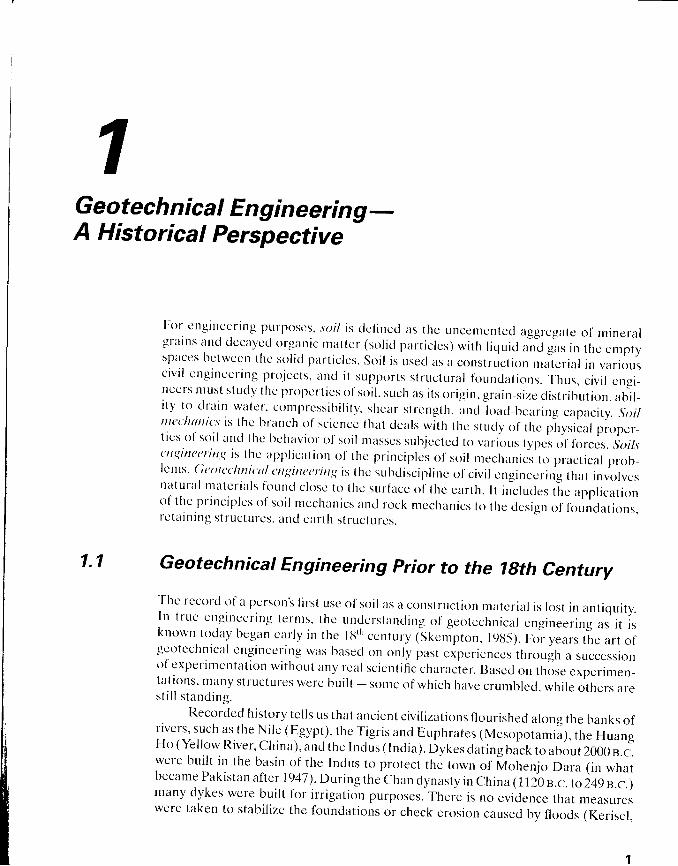
Figure 7.7 Lcaning -l irwcr ol ' pisa. Italv
l9{l-5)' Ancient Greek civil ization used isolated pad footings and strip-and-raft foun-dat ions for bui ld ing st ructures. Beginning arouncr 2 i50 s. i . . , the f ive most importantpyramids were built in Egypt in a period of less than a century (Saqqarah, Meidum,Dahshur South and North, and chcops). This posed formidatre chalrenges regard_ing foundations. stabil ity of slopes. and construction of underground chambers. Withthe arrival of Buddhism in china <luring the E,astern Hun ainurty in 6g a.n., thou_sands of pagodas were built. Many of these structures were consiructed on silt andsoft clay layers. In some cases the foundation pressure exceeded the load_bearing ca_pacity of the soil and thereby caused extensive structural damage.
one of the most famous examples of probrems related to Joil-bearing capacityin the construction of structures prior to the 1g,r, ."n,u.f L-irr" L.aning Tower ofPisa in l ta ly . (See Figure 1.1. ) Construct ion of the tower began in l t lz x .o.when the
1.1 Geotechnical Engineering Prior to the lgth Centurv
li
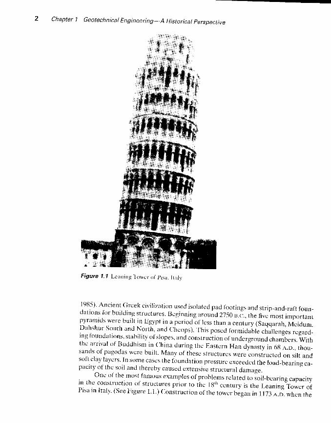
Figure 7.2 Ti l t ing o l Gar isenda lbwer ( lc l t ) in Bokrsna, l ta lv
Republic of Pisa was flourishing and continuecl in various stages for over 200 years.The structure wcighs about 1-5,700 mctric tons ancl is supported by a circulai basehaving a d iameter of 20 m ( : 66 f t ) . Thc towcr has t i l ted in thc past to the east , nor th,west and, f inally, to the south. Recent investigations showed that a weak clay laycrexists at a depth of about 1 1 m (: 36 ft) below the ground surface comprcssion, whichcaused the tower to ti l t. It is now morc than 5 m (: 16.5 ft) out of plumb with the54 m (: 119 ft) height. Figure 1.2 is an example of a similar problem. The towersshown in Figure 1.2 are located in Bologna, Italy, and they wcre built in the 121h cen-tury. The tower on thc left is usually referred to as the Gorisentlu Tswer. It is 48 m(: 157 ft) in height and has ti l ted severely.
After encountering several foundation-related problems during constructionover centuries past, engineers and scientists began to address the properties and
wH{
.t!:,
h,iil{4t
I
. . . \
f f - :- \$ x : ; I

Chapter 1 Geotechnical Engineering-A Historical Perspective
1.2
behavior of soils in a more methodical manner starting in the early part of the 18'ncentury. Basecl on thc cmphasis and the nature of study in the area of geotechnicalengineering, the time span extending from I700 to 1927 can be divided into four ma-jor per iods (Skempton, 198-5) :
1. Prc-c lass ical (1700 to 1776 a.o. )2. Classical so i l mechanics - Phase I (1716 to 1856 a.n. )3. Classical so i l mechanics - Phase I I ( 1 t t -56 to 1910 n.n. )4. Mirdern soil mechernics (1910 tct 1927 ,+.o.)
Brief descriptions of some significant developments during each of these lour peri-
ods are discusscd below.
Preclassical Period of Soil Mechanics(1700 -1776)
' l -h is pcr iod concentratcd orr s tudies rc lat ing to natura l s lopc and uni t weights of var-ious typcs of so i ls as wcl l as the semiempir ica l ear th prcssurc thcor ies. ln lT l l aFrcnch royal cngine er , Hcnr i Gurt t ier ( 1660 - 1737), s tuc l ied the natura l s lopes of so i lswhen t ippcd in a heap I 'or l 'ormulat ing the design procedures o[ reta in ing wal ls . Therttttttrul slopc is what wc now rcfcr to as the ungle ofrcposc. According to this study.the natural slope (se e Chapter I l) o| t: lcun dry sund and, ordinarv carth were 31" and215' . rcspcct ive ly . Also, thc uni t weight o l 'c lcan dry sand (sec Chaptcr 3) and ord i -n l r r y c l r r l h w c r c r c c ( ) m n r e n d c d l o h c l l J . I k N i n t r ( l l 5 l h / f t ' ) a n d l 3 . 4 k N / m ' ( l { . 5 l b / f t r ) .rcspcctivcly. No tcst rcsults on clay werc rcportcd. ln 1721), Bernarcl Forest de Beli-dor (1671-1161) publ ishcd a tcxtbook l 'or mi l i tary and c iv i lenginccrs in France. Inthe book, hc proposecl n thcory for lateral earth pressure on retaining walls (see
Chaptcr l2) thal was a lo lkrw-up to Gaut ier 's ( l7 l7) or ig inal s tudy. Hc i t lso speci l ieda soi l c lass i f icat iorr sys lcm in the manner shown in the fo l lowing tablc . (See Cihap-ters 3 and 4.)
Classif icat ion
Unit weight
kN/m3 lb/f t3
Rock
F i rm or hard sand(iompressible sand
Orcl inarv earth (as found in clry locations)Soft earth (primari ly si l t)Clay
Pcat
16.7 to 106 toI u.4 117r3.4 8.516.0 10218.9 120
The f,rst laboratory model test results on a 76-mm-high (: 3 in.) retaining wallbuilt with sand backfi l l were reportedin 1146 by a French engineer, Francois Gadroy(170-5-1759), who observed the existence of slip planes in the soil at failure. (See
Chapter 12.) Gadroy's study was later summarized by J. J. Mayniel in 1808.

t.3
1.4
1.4 Classical Soil Mechanics-phase il 0g56_tgl0) 5
Classical Soil Mechanics-Phase I (1776-1956)
Dur ing th is per iod, most of the developments in the arca of geotechnical engineer-ing came from engineers and scientists in France. In the preclassical pcrio<1, practi-ca l ly a l l theoret ica l considerat ions usccl in calculat ing la tera l ear th pressure on re-ta in ing wal ls were based on an arb i t rar i ly based fa i lure sur facc in soi l . In h is famouspaper presented in 1776. French sc ient is t Char les August in Coulomb (1736-1806)used the pr inc ip les of ca lculus 1 'or maximer ancl min ima to determinc thc t ruc pssi -t ion of the s l id ing sur l 'ace in soi l bchinc l a rc tar in ing wal l . (See Chapter 12.) In th isanalys is ' Coulomb uscd the laws of f r ic t ion ancl cc lhesion for so l id bocl ics. In l f i20.special cascs tlf Coulomb'.s work wcre stuclicd by Fre nch cngincer Jacqucs FrcclcricFrancais (177-5-1u33) and by French appl icc l mcchanics pro l 'cssor Cl laucle Leuis Ma-r ie Henr i Navier( l7 t t -5- l t i36) . Thesc spccia l cases re latcc l to inc l incd backt i l ls anclbackf i l ls support ing surchargc. In l lJ40. Jean Victor Poncclet ( l7Uu- l t j67) . i tn zr rmvcngincer and professor c l l 'nrcchanics. cxtcrrc lcc l Cloukl lb ls t l teory by prov ic l ing i rgraphical mcthod I 'or detcrmin ing thc rnagni tuc lc oI la tcra l car th prcssurc en vcr t ica land inc l incc l reta in ing wal ls wi th arb i t rar i ly brokcn polygonal srouncl sur f 'accs. p6n-cc let was a lso thc f i rs t to usc the syrrbol y ' r lbr so i l I ' r ic t ion anglc. (Scc Chaptcr l l . )He a lso providcc l thc I i rs l u l t i rnatc bear ing-capaci ty theory l r l r shal low l i runcl l t ions.(Sec Chapter l -5 . ) In lu46 Alcxancl rc C- 'o l l in ( l l l0 lJ l l . i90) . au cnginecr- . pr6v ic lcc l thcdeta i ls 1 'or decp s l ips in c lay skrpcs. cr - r t t ing. ancl crnbanknrcnts. (Sec C.haptcr 14.)Clo l l in thcor izcc l that in a l l cases the fa i lurc takcs p lace when 1 l . rc nrobi l izcc l cohcsioncxcccds thc ex is t ing cohcsion o l thc soi l . Hc a lso obscrvccl that thc actual I 'a i lurc sur-I 'accs coulcl bc approxir.natecl as arcs of'cycloids.
The cnd o l 'Phase I t t l ' thc c lass ical so i l mcchar. r ics pcr ioc l is gcncra l ly markccl bythe ycar ( lu-57) o l ' the f l rs t publ icat ion by Wi l l iam John Macquorn Rankinc (1g201872), a pr t l fcssor o l 'c iv i l enginecr ing at the LJnivcrs i ty o l 'Ci lasgow. This s tuc ly p1r-v ic lec l a nol .able theory on car th prcssurc and equi l ihr - iurn o l 'car th massct . (S""chapter 12.) Rankine ' .s t l " reory is a s impl i r icat ion o l 'coulornb 's lhc ' r -v .
Classical Soil Mechanics-phase II (Ig56-IgI0)
Scveral expcr imcnta l resul ts f rom laboratory tests on sani . l appeared in thc l i teraturcin th is phase. One o1' the car l ic 's t ancl most important publ icat ions is onc by Fre lc l . rengineer Henr iPhi l iber t Gaspard Darcy (1803- l l3-5t3) . In l8-56. he r rubl ishecl a s tudvon thc pe rmer rh i l i t y o f sanc l f i l t c r s . (See Chap te r h . ) B i r sed on those . tes t s . D i r r cy de ,fined the Ierm coe.fftc:ient of lternteubitit l , (or hydraulic conductivity) of soil. a veryuseful parameter in geotechnical engineering to this day.
Si r Georgc Howard Darwin (184,5-1912). a profcssor o[astronomy. conductedlaboratory tests to determine the ovcrturning moment on a hinged wall retaining sandin loose and dense states of compaction. Anothcr noteworthy contribution, whichwas published in 1885 by Joseph Valentin Boussinesq (1942-1929), was the develop-ment of the theory of stress distribution under loaded bcaring areas in a homoge-neous, semiinfinite, elastic. and isotropic medium. (See Chapter 9.) In lt i ttT, OsborneReynolds (1842-r912) demonstrated the phenomenon of dilatencv in sand.
Chapter lGeotechnicalEngineer ing-AHistor ica lPerspect ive
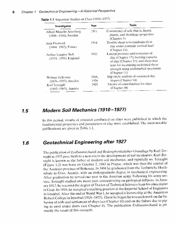
Table 1.1 Important Studies on Clays (1910-1927)
lnvestigator Topic
Albert Mauritz Atterbcrg(1U46-1916 ) , Sweden
Jean Frontard(11384-1962). France
Arthur LangtrY Bct l(11374-1956). England
Consistency of soi l , that is, l iquid.
plast ic, and shrinkage ProPertrcs(Chapter 3)
Doublc shear tcsts (undraincd) in
clay under constant vert ical lond
(Chapter 1 l )
Lateral prcssure nnd resistance t l f
clay (Cihaptcr 12); bcaring capacrty
of clay (Ch:rptcr 1.5); and shear-box
tcsts for mcasuring undrained shear
strcngth using undisturhed specimens
(t lhaptcr I I )Sl ip-circle analysis of saturated clay
s lopcs (ChaPter l4 )' fhcory o( consol idation ft l r clays
(Chapter l0 )
1 9 1 1
1 9 1 4
r 9 l 5
Wolmar Fcl lcnius(1 t t76 1957) , Swedcn
Karl Tcrzaghi( I l3l t3 - I 963). Austrta
I r l I t i .1926I 925
1.5
1.6
Modern Soil Mechanics (1910-1927)
In this period, results Of rcsearch conductecl on clays wcre publishecl in which thc
fundamcntal propcrtics i lnd parametcrs of clay werc established. '[ 'he most notablc
publ icat ions arc g iven in Tablc l . l .
Geotechnical Engineering after I 927
The publicat it'n of Erdbaumachanik auf'Botlenphl'sikalisher Gnmdlage by Karl Ter-
,agtri in 1925 gavc birth to a new era in the devclopment of soil mechanics' Karl Ter-
,u!ni i, known as thc father .f modern soil mcchanics, and rightfully so. Terzirghi
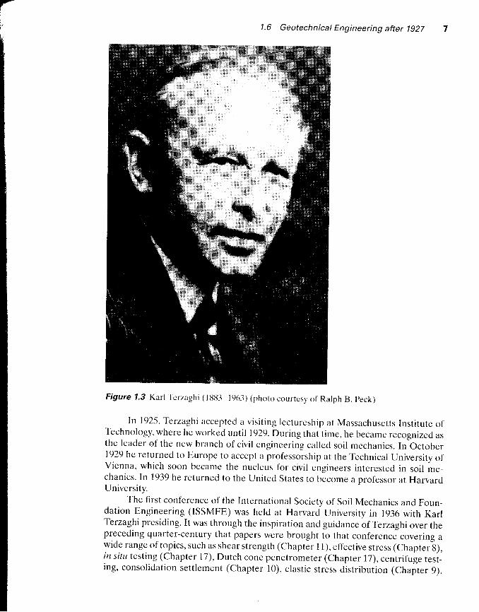
(Figure 1.3) was born on October 2, 1883 in Prague, which was thcn the capital of
ihJnrrt. iun province of Bohemia. In 1904 he graduated from the Technische Hoch-
schule in Graz. Austria, with an undergracluate degree in mechanical engineering'
After gracluation he served one year in the Austrian army. Following his army ser-
vicc, T-erzaghi stuclied one more year, concentrating on geological subjects' In Janu-
ary 1912,hJ receivecl the degrce of Doctor of Technical Sciences frclm his alma mater
in Graz. In 191 6, he acceptecl a teaching position at the lmperial School of Engineers
in Istanbul. After the end of World War I, he accepted a lcctureship at the American
Robert College in Istanbul (1918-1925). There he began his research work on the be-
havior of soils ancl settlement of clays (see Chapter 10) and on the failure due to pip-
ing in sancl under dams (see Chapter 8). The publication Erdbattmechanik is pti-
marilv the result of this research.
-
1.6 Geotechnical Engineering after 1927
Figure 7.3 Karl Tcrzaghi (l lJt33-1963) (phoro courtesy of Ralph B. peck)
In 192-5, Terzaghi acceptcd a visit ing lccturcship at Massachusetts Institute ofTechnology, where he worked unti l t929. During that t ime, he became recognized asthe leader of the new branch of civil engineering called soil mechanics. In October1929 he returned to Furope to accept a professorship at the Technical University ofVienna, which soon became the nucleus for civil engineers interested in soil me-chanics. In 1939 he returned to the United States to become a professor at HarvardUnivers i ty .
The first conference of the International Society of Soil Mechanics and Foun-dation Engineering (ISSMFE) was held at Harvard University in 1936 with KarlTerzaghi presiding. It was through the inspiration and guidance of Terzaghi over thepreceding quarter-century that papers were brought to that conference covering awide range of topics, such as shear strength (chapter l l), effective stress (chapter g),in situ testing (Chapter 17), Dutch cone penetrometer (Chapter 17), centrifuge test-ing, consolidation settlement (chapter 10), elastic stress distribution (chapter 9),
Chapter 1 Geotechnical Engineering-A Historical Perspective
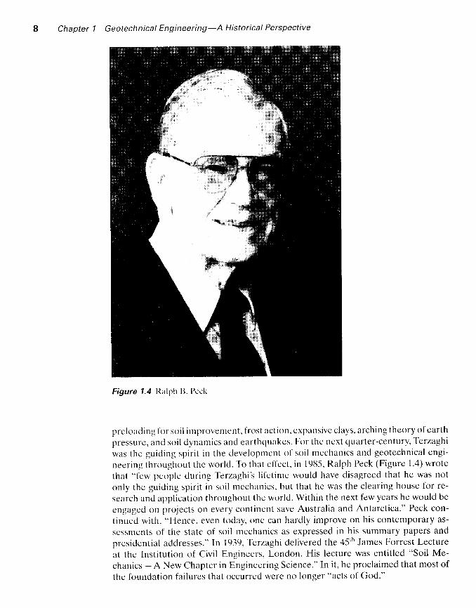
Figure 1.4 ltalph B. I)cck
prcloading l 'or soil irnprovcntcnt, I 'rost action. e xpansivc clays. arching theory of earth
pressure, arrd soil dynantics and earthquakcs. For the next quarter-century, Terzaghi
was thc guiding spirit in the clevelopment ol 'soil mechanics and geotechnical engi-
neering throughout the world. ' I
o that effect. in 1985. Ralph Peck (Figure 1 .4) wrote
that "few pcople during Terzerghi'.s l i fetime would have disagreed that he was not
only the guiding spirit in soil mcchanics. but that he was the clearing house for re-
search and application throughout the world. Within the next few years he would be
engaged on projects on every continent save Australia and Antarctica." Peck con-
tinued with, "Hence, even today, one can hardly improve on his contemporary as-
sessments of the state of soil mcchanics as expressed in his summary papers and
presidential addresses." In 1939. Terzaghi dclivered the 45th James Forrest Lecture
at the lnstitution of Civil Engineers, London. His lecture was entit led "Soil Me-
char.rics - A New Chapter in Engineering Science." In it, he proclaimed that most of
the foundation failurcs that occurred were no longer "acts of God."

7.6 Geotechnical Engineering after lg27 g
Following arc some highlights in the development of soil mechanics anil geo-technical engineering that evolved after thc flrst conference of the ISSMFE in tg:e:
' Publication of thc bctok Theorelical Soil Mcchttnics by Karl Terzaghi in 1943(Wiley. New Ycrrk);
r Publication of the book Soll Mechunit 's irt Engineering Prar:tice by Karl Terzaghiand Ralph Peck in 1948 (Wi ley. New york) ;
o Publication ol the book Ftrndamentols tf ' *t i l Mechunit 's by Donald w. Taylori n l ( ) 4u 1Wi l cy . Ncw Vr rk ) :
' Star t t r f the publ icat ion of Gcotet 'hn i r1uc, thc in ternat ional journal o l 'so i l me-chanics in l94 lJ in Enelancl ;
r Prcsentat ion o i the paper on d - 0 conccpt f 'or c lays by A. w. Skempton inl94t t (sce Clhaptcr I l ) ;
' Publ icer t ion o l 'A. w. Skcmpton' .s papcr on ,z l and B porc watcr prcssure param_eters in 19.5,1 (sce Chaptcr I l ) ;
r Publication tll'thc bo<lk Tlrc Mau.rrrrunutt o.f Soil I'ntpt,rtic.s' irr tha '['riu,riul
Tc5tby A. W. lS ishop and B. J . Hcnkcl in l9-57 (Arrro ld. Lonclon) .
. ASCE' .s Rescarch C'onf 'e rcnce on Shcar Strcngth o l 'Cohcsive Soi ls helc l i r rBoulc ler , C 'o lorado. in 1960.
Sincc thc car ly c lavs, the pr t l l 'e ss ion o l gcotcc l rn ica l cngince r ing has come u lonsway etnc l has maturcd. I t is now an cstabl ishecl br : rnch o l c iv i l cngineer ing. ancl theu-sancls o l 'c iv i l cns inccrs c lcc larc scotechnical cnt inccr ing to bc thc i r prc l 'cr rcd areaol 'specia l i tv .
Since thc f i rs t conl 'crcncc i r r lg36. cxccpt l i r r a br ic l in tcr r r - rpt ior- r c lur ing Wor ldWar I I . the ISSMFE conl 'crcnccs have bcen hcld at l i lur -ycar in tcrvals . In 1997. theISSMFE was char lgcc l to ISSM(l E ( In te rnat ional Socicty o l Soi l Mcchanics and ( ]cs-tcchnical Enginccr ing) to rc f icct i ts t rue scopc. T l . rcsc in te rnat ic lnalconf 'crences havebcen inst rumcnla l l i r r cxchange o l ' in l i r rmat ic ln rcuarc l ing r rcw c levckrpnrents and en-going rescarch act iv i t ics in gcotechnical cnqinccr ing. ' lhb lc
1.2 g ivcs thc lscat i1 ;n and
rable 7.2 De ta i ls o l ' ISSMFE ( 1936 lc l97) and ISSMCE ( l9r )T,prcscnr) c .onf crcnccs
Conference Locat ion Year
II II I II V
V IV I IV I I II XXX IX I IX I I IXIVXV
I la rvarc l Un ivcrs i tv . Bos ton . LJ .S .A.Roltcrdarn. t l rc Ncthe r lanclsZur ich , Swi tzc r landLondon. Ene landParis, FranccMont rca l , Canac laMcxico Cii{y, MexicoMoscow. U.S.S.R.Tokyo, JapanStockholm. SwcdenSan Francisco. tJ.S.A.Rio dc Janciro, Br: izi lNew Delhi, IndiaHamburg, Germanylstanbul, Turkey
I 936Ir)4uI 9531957l 9 6 llc)65I 969t973197719rJ I198-51989r99119972001
1 0 Chapter 1 Geotechnical Engineering-A Historical Perspective
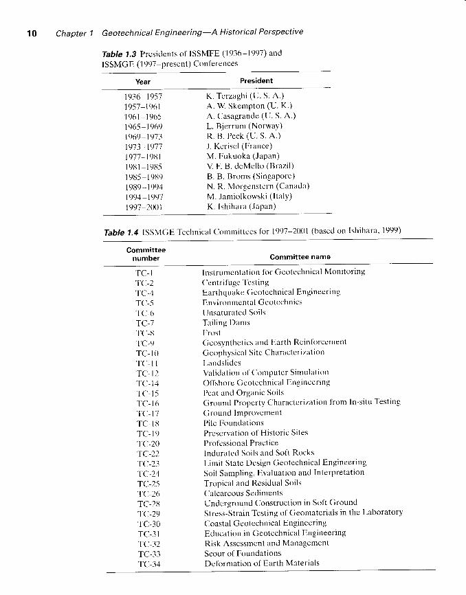
Tabte 1.3 Presidents of ISSMFE (1936-1997) andISSMGE ( 1997-present) Conferences
Year President
1936-19571957 -19611961-196.s1965 -1969t969 19731973,1977I977 - I9U1I 981 - l9rJ5I 98-5 - 191391 989, I 9941994-t99'7199'7 2001
K. Terzagh i (U. S . A . )A. W Skempton (U. K.)
A. Casagrande (U. S. A.)
L. Bjerrum (Norway)R. B . Pcck (U. S . A . )
J. Kerisel (France)
M. Fukuoka (Japan)
V. F. B. deMello (Brazi l)
B. B. Broms (Singapore)
N. R. Morgenstern (Canada)
M. Jamio lkowsk i ( l ta ly )
K . Ish ihara (Japan)
Table 1.4 ISSMGE Tcchnical Comrnittees ior 1997-2001 (bascd on Ishihara. 1999)
Committeenumber Committee name
TC-I'fcl-2
TC].4TC-.5'I'C-6
TC],7TC-tiTC.9TC- IOT C r - l lTC- I2TC. I4TC- l -51 'C- l6TCr-17T C . I 8TC- I9TC-20TC-22TC.23TC.24TC-2-5-fc-26
TC.28TC.29TC-30TC-3I'tc-32
TC.33TC-34
Instrumcntation l 'or Getttcchnical Monitoring
Centri l 'uge TcstingEarthquakc Gcotcchnical Engineering
Environmental Getttcchn tcs
lJnsaturatcd Soils' fai l ing
DamsFrostGcosynthetics and Earth Reinlt lrcement
Cicophysical Sitc CharactcrizationLandsl idcsVa l ida t ion o l Computer S imu la t ion
Of l ' shorc ( ieo techn ic l l Eng ince r i r lg
Pcat and Organic Soils
Ground Propcrty Charzrctcrizir l ion lrom In-situ Testing
Ground ImprovcmentPile FoundationsPrcscrv:rt ion of Historic Sites
Professional PracticeInduratcd Soils and Soft Rocks
Limit Statc Design Geotechnical Engineering
Soil Sampling, Evaluation and Interpretat ion
Tropical and Residual Soils
Calcareous SedimentsUnderground Construction in Soft Ground
Stress-strain Testing of Geomaterials in the Laboratory
Coas l r l Ccotechn ica l Eng inecr ing
Education in Geotechnical Engineering
Risk Assessment and Management
Scour of FoundationsDeformation of Earth Materials
References 11
year in which each confercnce of ISSMFEiISSMGE was held, ancl rable 1.3 givesa list of all of the presidents of the society. In 7997, a total of 30 technical commit-tees of ISSMGE was in place. The names of these technical committees are siven inTable 1.4.
ReferencesA't 'rnner-:nt; , A. M. ( 191 I ) . "Ube-r t l ie physikal ischc Boclenuntersuchung, und t jber dic plast i-
zi t i i t de ' Ionc."
International Mittei lungen ft i r Bodcnkunde. Verlag .f ' i i r Fuchl i tarutur.G . m . b . H . B c r l i n . V o l . l . l 0 - 4 3 .
Bnt.rtrcrt<. B.F. (1729). Ltr St:icnt'c des Ingenicurs rluns lu Condttitc tlcs'l'ruvau-r tlc Rtrtifit'ationct D'Architct ' turc Civi l , Jombcrl. Paris.
Bp: t . t - , A . L . ( l9 l -5 ) . "The La tc ra l Prcssure and Res is tancc o f C lav . and Suppor t ins Powcr 6 [clay Foundations," Min. Pntccading o.l'In.stitutc of'Civil Enginccrs, Vol. 199, 233 2j2.
BIstrtrp, A. W. and HttNrcttt . , B. J. (1957). T'hc Mcusurcnttnt o.f soi l Prcpert ies in thc 7-r iuriulZc.r '1, Arnold. London.
B<rttssrNt:stf . J. V. ( l l l l l -5). Applicution dcs Potenticls i L'F.tudc dc L' i : t lui l ibrc ct t lu Mortvt,-t tr c rt t d r, .s S o I i d cs El u s t i t 1 r t c s, Gauthicr-Vi l lars, Paris.
C'<ll-r.tN, A. ( lil46). Ilacharthas ['.,rp(rintcntult's sur la.s (]li.ssurturts Sporttune.s da.t 7-crrainsArgilatrx Attttntpugn(es dc (lonsid(ruliorts strr Qucltlut,s I'rint'iltcs da lu M(t'uniqua'll,r-rcs/rc, ( 'ar i l ian-Cioeury. Paris.
Cot t l .< ln ' t l t , C ' . A . (1776) . "E ,ssa i sur unc App l ica t ion dcs RDglcs de Max in t i s c t M in i rn is i jQuclqucs Probldnrcs cle Stat iquc Rclat i ls i ' r L'Architccturc," Minutirc.s t lc lu Muthinru-I iqrrc at da Phisit l trc, prdscnt6s t j I 'Acaddrric Royale dcs Scicnccs. par divcrs savans. ell0s dans s6s Asscmbldcs, De L' lrnprin'rcr ic Royalc. Paris. Vrl . 7. Annee 1793,3,13 382.
Dnt<t 'v. H. P. G. (11356). Las l i tntuirtcs [ ' rrbl iqtrcs r lc IuVil lc t la Di jon, Dalrnont. Paris.D n t r w t N , G . H . ( 1 8 8 3 ) . " O n t h c H o r i z o n t a l ' I ' h l u s t o [ a M a s s o l ' S a n d , "
] ' n t c c a t l i n t : s , I n s t i t u t co l 'C ' i v i l Eng inccrs . l -ondon, Vr l . 71 . 350 37S.
Ft ' t - t - t ,N t t rs . W. ( l9 l l J ) . "Ka j -och Jordrascn I Gr i tcborg . " ' l ' ckn i .sk ' l ' i t l , sk r i f ' t .
Vr l .4 lJ , l7 -19 .FR^N< ,a, ls. J. F. (1u20). "Rcchcrchcs sur la Pouss6c dc
' l 'e rrcs sur la Formc ct Dimensions des
Rcvetmcnts ct sur la Talus D'Excavation," M(nutr iu! dc L'Off i t ' icr du ()(nie, Paris, Vrl .IV. 1.57-206.
F t rc rNt , rn r> , J . (1914) . "No( icc sur L 'Acc ic len t c lc la D ieue de C lharmcs, " Anns . Pot t ts c t(lhuus.s(t::;9't' Sar., Vol. 23. 173,2()2.
Gnrrtrtrv, F. (1746). M(moire strr lu Poussta t les' l .crrcs, summarized by Maynicl. 1tt0t3.Gntlr ' rnn. H. (1717). Disscrtut ion sur L'Epaisseur das ()ul(cs t les I 'ott ts.. . sur t , 'Eft lr t et ul
['e.suntettr de:; Arrhe.s... el sur lcs f'roliles dc Mutonnt'rie qui Doivent Sultporter desChurtss(es, des
'l'errasses, et des Rempurl,r. Caillcau, Paris.
Isu t t tanR, K . (1999) . Persona l communica t ion .KF.ntsrt-, J. (198-5). "The History of Geotechnical E,ngineering up unti l 1700." Prot 'eetl i1gs,
XI lntcrnational Conlercnce on Soil Mcchanics and Foundation Enginecring, SanFranc isco . Go ldcn Jub i l cc Vcr lumc. A . A . Ba lkema.3-93 .
MavNter, J. J. (1808). Truit! E.rperimentale, Analytique et PratiqLrc tle la Poussi tles Terres.Colas. Paris.
Navten, C. L. M. (1839). Legons sur L'Aplt l icat ion de lu Micanique d L'Establ issenlent desCorrstructions et des Muchine.s, 2"d ed., Paris.
Pp.cr. R. B. (1985). "The Last Sixty Years," Proceedings, XI Intcrnational Conference on SoilMechanics and Foundation E,ngineering, San Francisco, Golden Jubi lee Volume. A. A.Ba lkcma. 123 l . l -1 .
PclNcnLE'r, J. V. (1840). Mlmoire sur la Stabilitt des Rev€tments et cle seurs Fsrttlutiols. Bache-l ier. Paris.
1 2 Chapter 1 G eotech n ica I E ng i n ee ri ng -A H isto rica I Pe rspective
R,rNrrNr. W J. M. ( l lJ57). "On the Stabi l i ty of Loose Earth," Phi losophical Transactions,
Royal Society. Vol. 147. London.
RuyN1;lr-ps, O. (1887). "E,xperinrents Showing Dilatency. a Property of Granular Material
Possibly Connccted to Gravi lat ion ." Proceaditrgs, Royal Socie ty. London, Vol. I 1, 354-
363.Sxnup lc tN. A .W. (1948) . "The r [ - 0 Ana lys is o f S tab i l i t y and I ts Thcore t ica l Bas is . " Pro-
t 'eatl incs, l l Inlernational f lonlerencc on Soil Mechanics and Foundaticln Engineering,
Rottcrdarn. Vrl . 1. 72-71t.
Srr:nrpr<rN. A. W. (1954). "-I 'he Porc Pressurc Coeli icicnts,4 and 8," ()ett tet:hnique, Vol.4,
t43 t17.Sxr,vrgr '<rN. A.W (19u.5). "A History of soi l Propcrt ies. l7l7 1927," I ' roceerl irrg.r, XI Inter-
na t iopa l Con l ' c rcncc on So i l Mcchan ics and Foundat ion Eng inee r ing . San Franc isco ,
Go lden Jub i l cc Vr lun te , A . A . Ba lkcnra .9-5 l2 l .- l- ;rvt.otr.
D. W. ( l91E). I :undurncntuls t t . l 'Soi l Mctl turtf ts, John Wilcy, Ncw York.' l ' l rrz,qc;r
rr, K. ( 192-5). [ . .r t lbutttr t t ' t l tunik uu.f ' tsodurphysikul ishcr Ciruntl lugc, Deutickc. Vicnna.' l ' r ,nzn i ; r r r . K . (1939) . "So i l Mcchan ics A Ncw Chapter in Eng i r rcc r ing Sc icnce, " lns t i tu tc
o f ' ( i v i l [ i t rg i t t cL ' rs . l r t r r rnu l , London. Vr l . 12 , No. 7 . 106-142.' l ' t , t<zn<; t r r . K . (1943) .
' l -hcorc t i<u l S t t i l M< ' thun i ts , John Wi lcy . Ncw Yt r rk .
' l 1rrz.t<;rrr. K. ancl Pr,r ' r . R. B. (194u). Soi l Mctlrunit 's i tr l ingirtL' t ' r i t rg I ' ruct ica,. lohn Wiley,
Ncw Ytrrk.
Origin of Soil and Grain Size
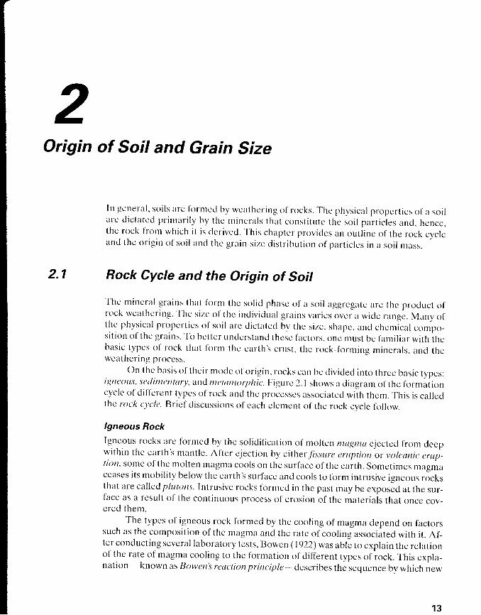
In gcneral . so i ls arc l 'or rncd bv wcat l " rcr ing of rocks. The physical propert ies c l l a soi larc d ic latcd pr in lar i ly by the mincra ls that const i tu tc the soi l p l r t ic les and. hcncc,thc rock I 'rorr which it is dcrivccl. This chaptcr proviclcs an outl ine of the reck cvclcancl thc or ig in o l 'so i l ancl thc gra in-s izc d is t r ibut ion of par t ic lcs in a sgi l l r r rss.
2.1 Rock Cycle and the Origin of Soil
Thc n l incra l gra ins that l i l r rn the sol ic l phasc o l 'a soi l aggrcgi l tc arc thc product 1; lrock wcather inc. ' l ' l rc s izc t l l ' thc indiv ic lual gra ins var ics < lvcr a wic le rangc. Many ofthc physical propcr t ics o l 's t t i l arc c l ic ta lcc l by the s ize. shapc, ancl chcmic l l compe-s i t i t ln o l ' thc gra ins. ' fo
bct tcr undcrstand thcsc lactors. onc must bc I 'ami l iar wi th thebasic typcs o l ' rock that lorn ' r thc car th ' .s crust , thc *rck- l i r r r r i 'g mi 'cra ls . and thewcir thcr ing pt ' ( )cc\ \ .
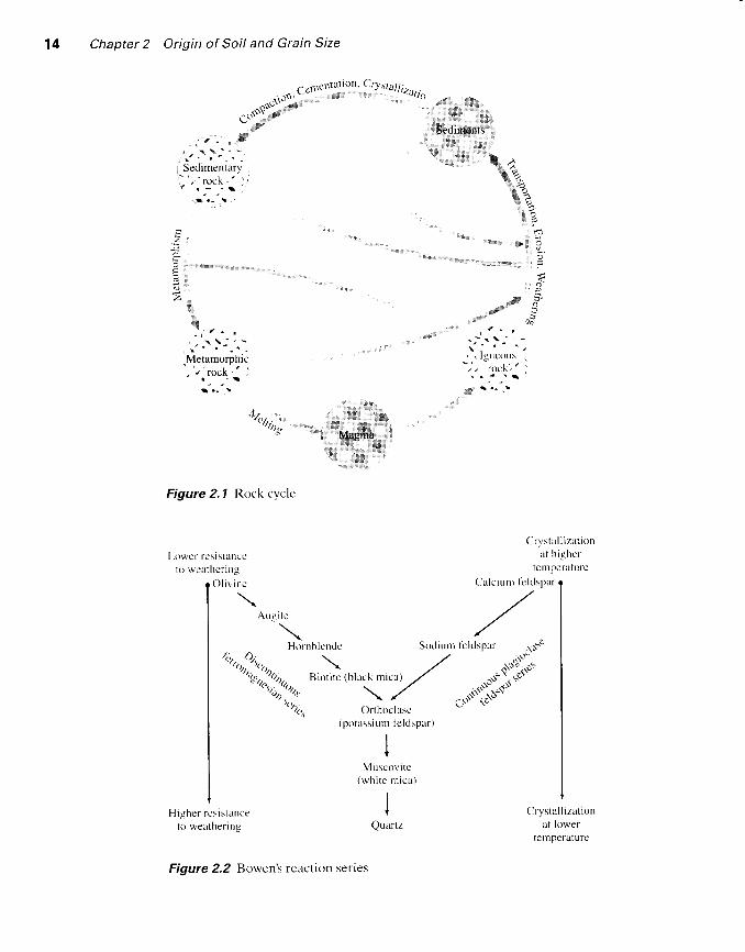
On thc basis ol their ntttclc ol 'origin, rocks car'r bc cliviclecl into three basic types:i l4trcrttt 's, scdintentury, artd rtretumorphit '. F igurc 2. I shows a cliagram of the fclrmalioncyclc o l 'd i l lc rent types o l ' rock and thc processcs associatec l wi th them.
' fh is is ca l lec l
Lhe roc 'k cvc lc . Br ie l 'd iscussions o l 'cach c lemcnt o l ' thc rock cvc lc fo l low.
lgneous Rock
Igncous rocks are forr.ncd by thc solidil ication of n.rolten mullnlu cjectcd from deepwithin the earth'.s mantle. Al'ter cjection by either,Ttssure erttption or vttlt.Ltrt iL crup-I ior i , somc of the rnc l l ten magma cools on the sur facc of the ear th. Somet imes magmaceiises its mobil ity below thc carthls surlacc and cclols to form intrusive igneous rocksthat are called plutons. Intrusive rocks krrmecl in the past may be exposcd at the sur-face as a result of the continuous process o1'erosion of the materials that once cov-cred them.
'rhe typcs of igneous rock ftrrmed by the cooling of magma depend on factors
such as the composition of the magma and the rate ol cooling associated with it. Af-ter conducting several laboratory tests, Bowen (1922) was ablc to cxplain the relationof the rate of magma cooling to the formation of different types of rock. This expla-nation - known as Bowen's reaclittn principle* describes the sequence by which new
1 3
1 4 Chapter 2 Origin of Soil and Grain Size
i r \ _ , i
Sedimentary/ rOCK,
r - . t ,
€C ..;! i:..,;.r;!r.]r
j ; . - ,' r \ ' -
Metamomhic, / rocK
r :
f_. "
-,t
a l t : ' . : , , , . . .
4",4vi,,,,t.! ,
I,tUg; "
i , t ; ' " ' b t l r ,
Figure 2.7 Rock cyclc
[ -owcr resistance1o weathcr ing
Crystal l izat ionl t h ighcr
tomperaturc
Crystal l izat ionat lower
temperature
(potussium I'eldspar.t
IV
Muscovi tc(whi te rn ica)
It
QuartzHigher rcs istance
to weather ing
Figure 2.2 Bowcn'.s reaction serles
2.1 Rock Cycle and the Origin of Soit 15
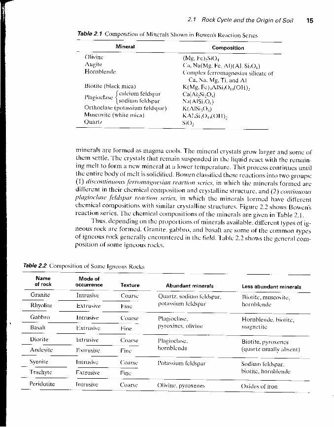
Table 2' 1 composition of Minerals Shown in Bowcn! Reaction Scries
Composit ion
OlivineAugiteHornblende
Bioti te (black mica)
plasiocrrrsc { ca lci um
. lc, lclsp.rIso f l1x6 lc ldsPar
Orthoclase (potassium feldspar)Muscovite (white mica)Quartz
(Mg. Fe),SiOaCa. Na(Mg. Fc, Al)(Al. Si2Oo)Cornplcx i 'erromagnesian si l icate of
Ca. Na. Mg, T i , and A lK(Mg. Fe) lA ls i ro ro(OH)rCla(AllSi,O*)Na(AlSi3O5)K(A lS i rOs)K A l r S i r O r o ( O H ) rsior
mlnerals are formed as magma cools. T'ht: mincral crystals grow larger ancl some ol'them set t le . The crysta ls that remain suspenclc<l in thc l iqu id react wi th the remer in-ing mel t to form a new mincra l at a lowcr tcntpcraturc. ' l 'h is
process cont inues unt i lthe cnt i rc body of nte l t is so l id i f ied. IJowen c lass i f icc l thcsc rcact ions in to two groups:(1) discontirutous .ferrutntagnesiurt reut'tion st:nc.r, in which thc mincrals forrnccl arcdi fTerent in thei r chemical composi t ion ancl crysta l l ine st ructurc, and (2) <:ont inuou,rplugilrclase .fcld'spur rcut'liott scrft's, in which the ntinererls l'ormed have dill'erentchemical c<l rnposi t ions wi th s imi lar crysta l l inc s t ructures. F igure 2.2 shows Bowen' .sreact ion ser ics. Thc chcmiczt l composi t ions c l l ' thc mincra ls are g iven in Table 2.1.
Thus ' dcpending on thc proport ions o1 ' r r incru ls avrr i lab le, d i l ' lere.nt types of ig-neous rock arc I 'ormed. Granilc, gabbro, anci baserlt arc some of the common typesof igneous rock gencral ly encountcred in thc l ie ld. fable 2.2 shows the gencral com-position clf some igneous rocks.
Table 2.2 Composition of Somc Igneous Rocks
Nameof rock
Mode ofoccurrence Texture Abundant minerals Less abundant minerals
Granite Intrusive Coarse Quartz, sodiunr l 'c lclspar.potassiurn tcldspar
B io t i t c , muscov i tc ,hornb lcndeRhyolite Extrusive Finc
Gabbro Intrusive Coarse Plagioclasc.pyroxincs, ol ivinc
Hornblendc. biot i te.magnetl teBasalt Extrusive
Diorite Intrusive Coarse Plagioclasc,hornblendeAndesite Extrusive
Bioti te, pyroxenes(quartz usually absent)Fine
Syenite Intrusive Coarse Potassium fcldspar Sodium feldspar,biot i te, hornblendeTrachyte E,xtrusive
Peridoti te Intrusive Coarsc Olivine. pyroxenes Oxides of iron

1 6 Chapter 2 Origin of Soil and Grain Size
Weathering
Weathering is the process of breaking down rocks by mechunicul and chemical pro-ce.r.res into smaller picces. Mechanical weathering may be caused by the expansionand contraction of rclcks frcn.r the cclntinuous gain and loss of heat, which results inultimatc disintegration. Frequently, water seeps into the pores and existing cracks inrocks. As the tempcrature drops, the watcr freezcs :rnd expands. The pressure ex-erted by ice because of volume cxpansion is str"clng cnough to break down even largerocks. Other physical agents that hclp disintesratc rocks arc glacicr ice. wind. t l.rc run-ning water of streams ancl rivcrs. and occzrn waves. It is important to realizc that inmechanical weather ing. lar rgc rocks arc broken down into srnal ler p icces wi thout anychange in the che nt ica l cctmposi l ion. F igure 2.3 shows several cxamplcs of mechani-cal eros ion duc to occi ln waves and wind at Ychl iu in Taiwan. ' fh is
area is located ata l t lng ancl narrow sca cape at the nor thwest s ic le of Kcelune, abor-r t [ -5 k i lomete rs be-tween the nor th coasl of 'Chin Shan and Wanl i .
In c l . rcnr ica l weather ing, the or ig inal mck rn incra ls are t ransl ' r l rmcd into newminerals by che rn ica l react ion. Water and carbon d iox ide l l 'orn thc at r rosphcre l i l rmcarbonic ac id. which reacts wi t l . r thc cx is t ing rock mincra ls to l i r rn ' r ncw mincra ls anclsoluble sal ts . Solublc sal ts present in thc grounclwatcr arrd orsanic ac ids l i r rmcd f romclecayecl organic ntat tcr a ls t t causc chcmical wcat l rcr ing. An cxarnplc o l ' thc chemi-cal weathcr ing o l 'or thoclasc to l i l r r l c lay mincra ls , s i l ica. and solublc Dotassiurn car-bonate l i r lk lws:
H'o + t'"'1,:,":.t]:,,in + (Hco'})
2 K ( A l s i r O s ) + 2 H ' + H , C ) - + 2 K ' + , l S i O , + A l . S i r O s ( O H ) rorlrr.crrts' lr Siric':r
,.,1i ' l ] l i l l l , ,,,,
Mt ls t of ' lhc potassiut r t ions rc lcasccl arc carr icc l away in solut ion as potussium car-bonate is taken up by p lants.
' l ' l .rc cher.nical wcathering ol' plagioclasc I 'eldspars is sirnilar to that oI ortho-
c lasc in that i t pr t tduccs c lay r r incra ls . s i l ica. and c l i f l 'c rent so lublc sal ts . Ferromag-ncsian mincra ls a lso l i r rnt the dccomposi t i< ln products o l c lay mincra ls , s i l ica, anclsoluble sal ts . Adcl i t ional ly . the i ron und magncsiurn in ferromagnesian minerals rc-sul t in othcr products such as hen"ra l i lc ancl l in toni tc . Quartz is h ighly rcs is tant towcather ing and only s l ight ly so lublc in watcr . F igure 2.2 shows the susccpt ib i l i ty ofrock-f<lrming minerals to wcathering.
'fhc minerals formecl at higher remperarures
in Ilowcn's reacticln series arc lcss rcsistar.rt to weathering than those formed at lowertcmperatures.
Thc wetrthering process is not l imited to igneous rocks. As shown in the rockcycle (F igure 2.1) , sedimentary and metamorphic rocks a lso weather in a s imi larmanner.
Thus, from the preceding brief discussion, we can see how the weathering pro-cess changes scll id rock masses into smaller fragments of various sizes that can rangefrom large boulders to very small clay particlcs. Uncemented aggregates of thesesmall grains in various proportions form different types of soil. The clay minerals,

i : , : * i : . . .
a . . l : '
v 6f":* ,,r ffi{&Figure 2.3 Mcchanical crosron
duc to ocean wavcsand w ind a t Yeh l iu .' faiwan
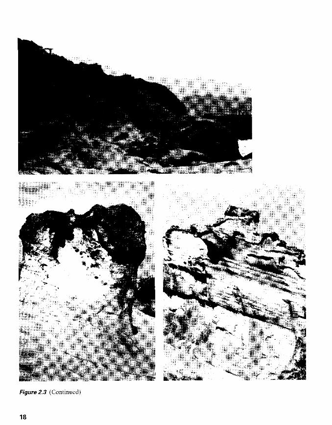
Figure 2.3 (Continued)
1 8

2.1 Rock Cycle and the Origin of Soil 19
which are a product of chemical weathering of feldspars, ferromagnesians, and mi-cas, give the plastic property to soils. There are three important clay minerals: (1) kao-linite, (2) illite, and (3) montmorillonite. (We discuss these clav minerals later in thischapter.)
Transportation of Weatheri ng Products
The products of weathering may stay in the same place or may be moved to otherplaces by ice, water. wind, and gravity.
The soils formed by the weathered products at their place of origin are calledresidual srti ls. An important characteristic of residual soil is the gradation of particlesize. Fine-grained soil is found at the surface, and the grain size increases with depth.At greatcr depths, angular rock fragments may also be founcl.
The transported soils may be clitssif ied into several groups, depending on theirmode of t ransportat ion and deposi t ion:
l. Gluciul soil.s- formed by transportation and deposition of glaciers2. Alluviul soil.s- transported by running water and deposited along streams3. Lourstrine soils- formed by deposition in quict lakes4. Murine soils- formcd by clcposition in the scas5. Aaolian.roil,r- transported and deposited by wind6. Colluvialsr., l ls- formed by movemcnt of soil from its original place by gravity,
such as dur ing landsl ides
Sedimentary Rock
The deposits of gravcl, sand, silt, and clay formcd by wcathering may bccome com-pacted by overburden pressurc and cemcnted by ergents l ike iron oxide, calcite, dolo-mitc, and quartz. cementing agents are generally carried in solution by ground-watcr. They fi l l the spaces belween particles and form sedimentary rock. Rocksformed in this way are called tletrital .sedimentory rr.,cks. Conglomeratc, breccia, szrncl-s tone, mudstone, and shalc are some examples of the detr i ta l type.
Sedimentary rock can also bc formed by chemical processes. Rocks of thistype are classified as chemicul sedimentary rocl<. Limestone, chalk, dolomite, gyp-sum, anhydrite, and others belong to this category. Limestone is formed mostly ofcalcium carbonate that originates from calcite deposited either by organisms or byan inorganic process. Dolomite is calcium magnesium carbonate IcaMg(coj)2]. It isfbrmed either by the chemical deposition of mixed carbonates or by the reaction ofmagnesium in water with l imestone. Gypsum and anhydrite result from the precipi-tation of soluble CaSoa because of evaporation of ocean water. They belong to aclass of rocks generally referred to as evaporircs. Rock salt (Nacl) is another ex-ample of an evaporite that originates from the salt deposits of seawater.
Sedimentary rock may undergo weathering to form sediments or may be sub-jected to the process of metamrtrphism to become metamorphic rock.
Metamorphic Rock
Metamorphi.sru is the process of changing the composition and texture of rocks, with-out melting, by heat and pressure. During metamorphism, new minerals are formed
Chapter 2
2.2
Table 2.3 Part icle-Sizc Classi l icat ions
Origin of Soil and Grain Size
and mineral grains are sheared to give a foliated texture to metamorphic rocks. Gran-
ite, diorite, and gabbro become gneisses by high-grade metamorphism. Shales and
mudstones are transformed into slates and phyll ites by low-grade metamorphism.
Schists are a type of metamorphic rock with well-foliated texture and visible flakes
of platy and micaceous minerals.Marble is formed from calcite and dolomite by recrystall ization. The mineral
grains in marble are larger than those present in the original rock. Quartzite is a meta-
morphic rock formed from quartz-rich sandstones. Sil ica enters into the void spaces
between the quartz and sand grains and acts as a cementing agent. Quartzite is one
of the hardest rocks. Under extreme heat and pressure, metamorphic rocks may melt
to form magma, and the cycle is repcated.
Soil-Particle Size
As discussed in the preceding section, the sizes of particles that makc up soil vary
over a wide range. Soils are gencrally called gravel, sand, silt, or c/ay, depending on
the predominant size of pnrticles within the soil. To describe soils by their particle
size, sevcral organizations have developcd particle-size classifications. Table 2.3
shows the particlc-size classifications developed by the Massachusetts Institute of
Technology, the U.S. Department of Agriculture, the American Association of State
Highway and Transportation OfTicials, and thc U.S. Army Corps of Engineers and
U.S. Bureau of Reclamation. In this table, thc MIT system is presented for i l lustra-
tion purposes only. This system is important in the history of the development of the
size l imits of particles present in soils; howcver, the Unified Soil Classification Sys-
tem is now almost universally acceptecl and has been adopted by the American So-
ciety for Testing and Materials (ASTM).
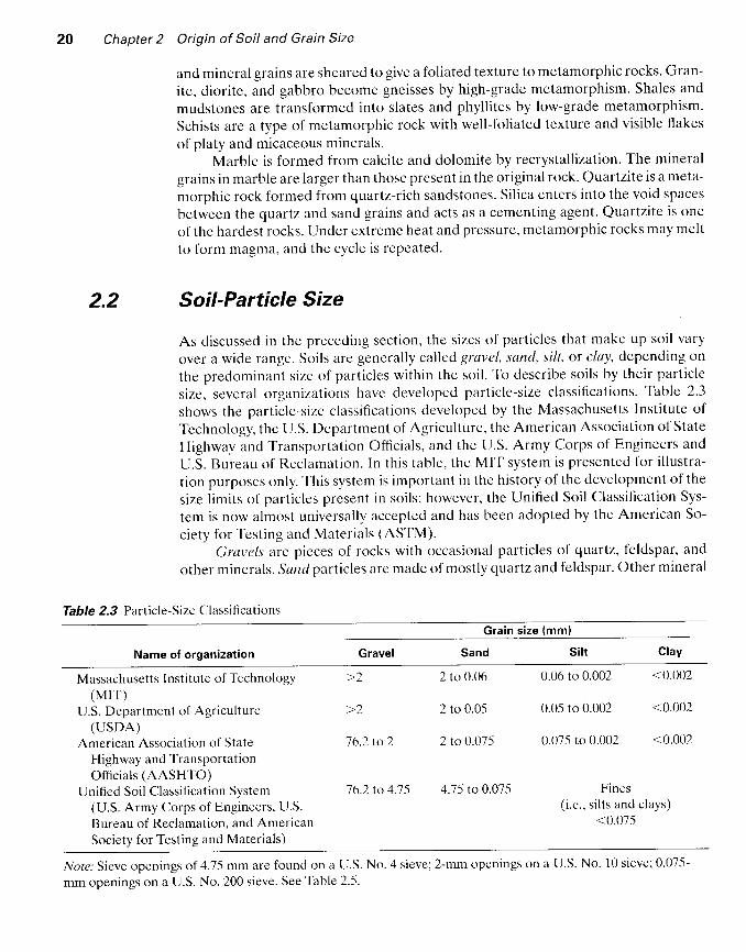
Gravals are picces of rocks with occasional particles of quartz, feldspar, andgther minerals. Sand particles are murdc of mostly clnrLz and feldspar. Other mineral
Grain size (mml
Name of organization Gravel
Massachusetts Institute of Technology(MIT)
U.S. Department of Agriculture(USDA)
American Association of StateHighway and TransportationOfficials (AASHTO)
Unified Soil Classification System(U.S. Army Corps of Engineers, U.S.Bureau of Reclamation. and AmericanSociety for Testing and Materiais)
76.2 to 2
76.2 to 4.75
2 to 0.06
2 to 0.05
2 ro 0.07,5
4.75 to 0.075
0.06 to 0.002 <0.002
0.05 to 0.002 <0.002
0.075 to 0.002 <0.002
Fines(i.e., si lts and clays)
<0.075
No/e: Sieve openings of 4.75 mm are found on a U.S. No. 4 sieve; 2-mm openings on a U.S. No. 10 sieve; 0.075-
mm openings on a U.S. No. 200 sieve. See Table 2.5.
2.3
2.3 Clay Minerals 21
grains may also be present at t imes. Sl/t"r are the microscopic soil fractions that con-sist of very fine quartz grains and some flake-shaped particles that are fragments ofmicaceous minerals. Cloys are mostly f lake-shaped microscopic and submtroscopicparticles of mica, clay minerals, and other minerals.
As shown in Table 2.3, clnys are generally delined as particles smaller than0.002 mm' However. in some cases. particles bctween 0.002 and 0.005 mm in size arealso referred to as clay. Particlcs classified as clzry on the basis of their size may notneccssarily contain clay mincrals. Clays have bcen defined as thosc particles ,.whichdevelop p last ic i ty when mixed wi th a l imi ted amount of water , ' (Gr im, 1953). (p las_ticity is the puttylike property of clays that contain a certain amount of water.) Non-clay soils cern contain particlcs of quartz. fcldspar, or mica that are small enough tobe within thc clay classification. Hence, it is appropriate for soil particle, ,11ull",than 2 microns (2 pm). or -5 microns (-5 pm) as defined uncler cliffcrent systems, to becalled clay-sized ptrrt icles rather than clay. Cilay particles are mostly in the colloidalsize range (< I g,m). and 2 pm ilppcitrs to be the upper l irr-rit.
Clay Minerals
Clay minerals arc complex a luminum si l icatcs composccl of two basic uni ts : ( l ) s i t icaletrtthedrcn and (2) uluminu ot'tohcdnttr. E,ach tctrahcclron unit consists oI four oxv-gcn atoms surrc lunding a s i l icon atom (Figurc2.4t ' r ) . Thc cr tmbinat ion of te . t rahecl ra lsil ica units gives a sil ic'u shcct (Figurc 2.4b). Threc oxygcn atoms at the base of eachtetrahcdron are sharcd by neighbor ine tc t rahecl ra. Thc octahedrzr l uni ts consist ofs ix hydroxyls surrounding an a luminum atom (Figure 2.4c) , an<l the combinat ion ofthe octahedral alun.rinum hydroxyl units gives an ottuhctlrul sheet. (This is also calleda gibbsitc sheat- Figure 2.4c1.) Sonretimes masncsium replaces the aluminum atomsin thc octahedral uni ts ; in th is casc, thc octahedral shcet is ca l lcd a bruc i te sheet .
In a s i l ica shect , each s i l icon atonr wi th a posi t ive charge of four is l inked to fouroxyge n ertoms witl"t a total negative chargc of cight. But each oxygen atom at the baseof the tet rahedron is l inkcd to two s i l icon i l toms. This mcans that the top oxygen atomof each tetrahedral unit has a negative chzrrgc of one to be counterbalanced. Whenthc sil ica shcet is stacked <lver thc octahedral sheet as shown in Figure 2.4e, these oxy-gen atoms replace the hydroxyls to balance their charges.
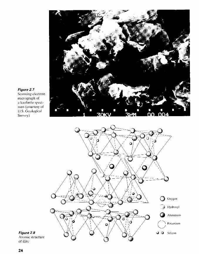
Of the three importzrnt clay mincrals, kaolinita consists of repeating layers ofelemental sil ica-gibbsitc shects in a 1 : I latt ice as shown in Figures 2.5 and 2.6a. Eachlayer is about7.2 A thick. Thc lerycrs arc held togerher by hydrogen bonding. Kaolin-ite occurs as platele-ts, each with a lateral dimension of 1000 to 20,000 A and a thick-ness of 100 to 1000 A. ttre surface area of the kaolinite particles per unit mass is about15 m2lg. The surface area per unit mass is defined as sp'ecific sur.iace. Figure2.7 showsa scanning electron micrograph of a kaolinite spccimen.
I// ite consists of a gibbsitc sheet bonded to two sil ica sheets - one at the too andanother at the bottom (Figures 2.8 and 2.66). rt is sometimes called ctay mic.i. Theil l i te layers are bonded by potassium ions. The negative charge to balance the potas-sium ions comes from the substitution of aluminum for ro-" ri l i .on in the tetrahedralsheets. Substitution of one element for another with no change in the crystall ine

Chapter 2 Origin of Soil and Grain Size
ffi a f-) o*yg"n
( a )
ffi a f-) Hydroxyl
( c )
o & Si l icon
( b )
@#
( e )
Figure 2.a @) Si l ica tetrahedron; (b) si l ica sheet; (c) alumina octahedron; (d) octahedral(gibbsite) sheet; (e) elemcntal si l ica-gibbsite sheet (after Grim, 1959)
;t o'r/ '
,jt t
1 i_L /
ffi o*yg"n
Hydroxyl
A lum inum
S i l r con

2.3 Clav Minerals 23
db o*yg"n
Hydroxyl
@ Atuminr,' '
6D 0 Sit icon
Figure 2.5 Atomic structure ol kaol initc (altcr Grim. l9-59)
Potassium 1Basal
spacingvariable-fiom
9.6 A to completeseparatlon
__L\d / ( t r )
Figure 2.6 Diagram of the structures of (a) kaolinite; (b) ilrite; (c) montmorilronite
\-%---___-7\
Silicasheet /
I-----------*{I
Gibbsite sheet I
,,2 Silica sheer
\nH.O and exchangeable cationsI
l .I
O A
IIL r
II
, l L
I
h',,'\l")i /K
@'ri \^
_L/',,
Gibbsite sheer
d*
Figure 2.7Scanning electronmicrograph ofa kaol inite speci-men (courtesy ofU.S. GeologicalSurvey)
Figure 2.8Atomic structureof i l l i te
24
i)fK\
/ / , q \ \ \ /
r*?@_l;(,,\/ o ' r - 'h'{}d - - - - - _ #
,.,,,,ii
@{ t
Oxygcn
Hydroxyl
Aluminum
Potassium
@ i3 Siticon
2.3 Clav Minerals 25
{*-:@_) @
t :tut# o^yg"n
@ Aluminurn, iron,
o o
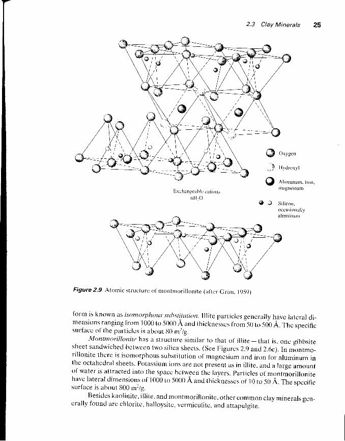
Figure 2.9 Atontic struclure of montmoril lonite (af'tcr Grim. I9-59)
form is known as isrtmorphous substitLrlion. lllite particles generally have lateral di-mensions ranging from 1000 to 5000 A ancl thicknesses from -50 to sog A. rne specificsurface of the particlcs is about 80 m2ls.
Montnnril lonite has a structure .similar to that oi i l l i te - that is, one gibbsitesheet sandwiched between two sil ica sheets. (See Figures 2.9 and2.6c). lnmontmo_ril lonite there is isomorphous substitution of magnJsium and iron for aluminum inthe octahedral sheets- Potassium ions are not present as in i l l i te, and a large amountof water is attracted into the space between the layers. Particles of montmoril lonitehave lateral dimensions of 1000 ro 5000 A and thicknesses of 10 to 50 A. The s|eci6;surface is about 800 m2is.
Besides kaolinite, i l l i te, and montmoril lonite, other common clay minerals gen-erally found are chlorite, halloysite, vermiculite, and attapulqite.
Exchangcablc cat ionsnH .o
magneslul l )
S i l i con ,occasional lyalu minunr
Chapter 2 Origin of Soil and Grain Size
+ + +
+ - + + +
- +
+ + + - + -
+
+ + + +
+ - + - +
(a )
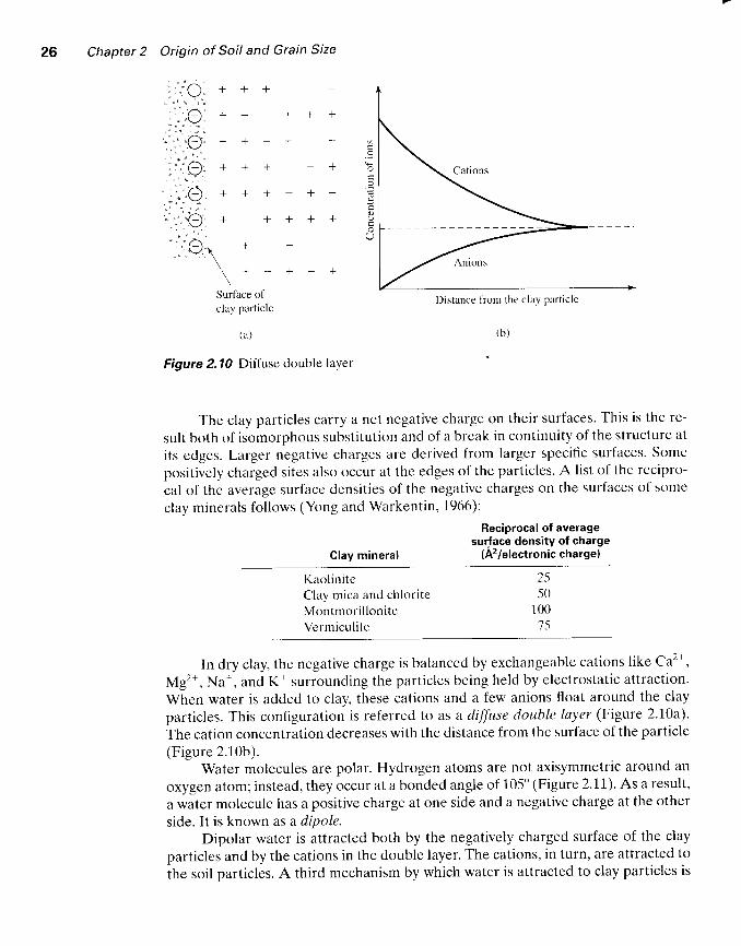
Figure 2. 10 Diffuse double layer
The clay particles carry a net negative charge on their surfaces. This is the re-
sult both of isomorphous substitution and of a brcak in continuity of the structure at
its edges. Larger negativc chargcs are derived from larger specific surfaces. Some
positively charged sites also occur at the edges of the particles. A l ist of the recipro-
cal of the average surface densities of the negative charges on the surfaces o[ some
clav minerals follows (Yong and Warkentin, 1966):
Reciprocal of averagesurface density of charge
(A2lelectronic charge)
a
a
aO
Clay mineral
KaoliniteClay mica and chlori teMontmori l loniteVermicul i te
In dry clay, the negative charge is balanced by exchangeable cations l ike Ca2*,
Mg2*, Na*, and K* surrounding the particles being held by electrostatic attraction.
When water is added to clay, these cations and a few anions float around the clay
particles. This configuration is referred to as a diffuse double layer (Figure 2.10a).
The cation concentration decreases with the distance from the surface of the particle
(Figure 2.10b).Water molecules are polar. Hydrogen atoms are not axisymmetric around an
oxygen atom; instead, they occur at a bonded angle of 105'(Figure 2.11). As a result,
a water molecule has a positive charge at one side and a negative charge at the other
side. It is known as a dipole.Dipolar water is attracted both by the negatively charged surface of the clay
particles and by the cations in the double layer. The cations, in turn, are attracted to
the soil particles. A third mechanism by which water is attracted to clay particles is
2550
100'75
Distance fiom the clay particle

2.3 Clay Minerals 27
Hvdrosen '/
u t"t
Figure 2.11 Dipolar character of water
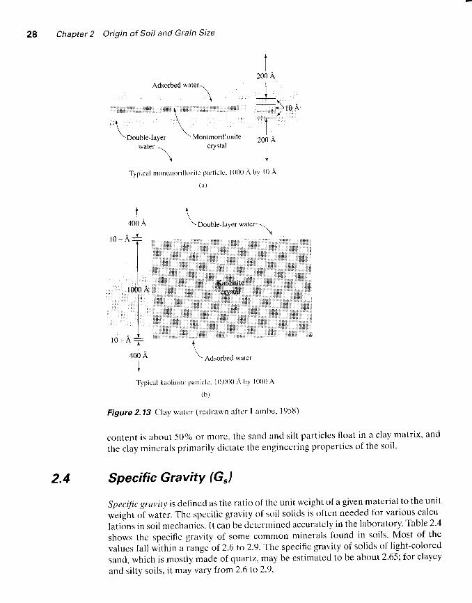
lrydrogen bonding, where hydrogen atoms in the water molecules are shared withoxygen atoms on the surface of the clay. Some partially hydrated cations in the porewater are also attractcd to the surface ofclay particles. These cations attract dipolarwater molecules. All these possible mechanics of attraction of water to clay are shownin Figure 2.12. Thc lorce of attraction between water and clay decreases with dis-tancc from thc surfetce of thc particles. All the watcr held to clay particles by fbrceof irttraction is known as double-luyer woter. The innermost layei of double-layerwater' which is hcld vcry strongly by clay, is known as aclsorbecl water. This water ismore viscous than free water is.
Figure 2.13 shows the absorbed and double-layer water for typical montmoril-lonite ancl kaolinite particles. This orientation of water around the clay particles givesc lay so i l s t hc i r p l as t i c p rope r l i c s .
It needs to be wcll recognized that the presence of clay minerals in a soil aggre-gate has a great influence on the engineering properties of the soil as a whole. Whenmoisture is present, thc enginecring behaviclr of a soil wil l change greatly as the per-centage of clay mineral content increases. For all practical purposes, when the i lay
Dipolarwatermoleculc
+ _
6+
molecule
{- l\$t
{p
Figure 2.12 Attraction of dipolar molecules in diffuse double laver
Chapter 2 Origin of Soil and Grain Size
Adsorbed water\
\. +
\r \\ \\ \
\Double-layer \ Montmorillonitewatet
\ crystal
\
tI
200 A
It
<-+
*T-I
200 A
I*
r 0 A
Typical r rontnror i l loni te part ic le. l0t )0 A by l0 A
( t r )
t , : : ,
t400 A. t
1IIt "
1m0AIIIIJt
400 A
l
\\ Double-layer water*\
' 'Kgolinite''ilff-
\\ Adsorbed water
TyPier l k r r , ' l i r t i t . ' p ; r r t i c l . ' ' l o ' { ) (X) n h1 l {X) { } A
( b )
Figure 2.13 Clay watcr (redrawn al ' tcr Larnbe. l95l l)
content is about 50% or more, the sancl ancl si l t part icles f loat in a clay matrix, and
the clay minerals primari ly cl ictate the engineering propert ies of the soi l .
2.4 Specific Gravity (G,)
Specific gravity is defined as the ratio of the unit weight of a given material to the unit
weight of water. The specific gravity of soil solids is often needed for various calcu-
lations in soil mechanics. It can be determined accurately in the laboratory. Table 2.4
shows the specific gravity of some common minerals found in soils. Most of the
values fall within a range of 2.6 to 2.9.The specific gravity of solids of l ight-colored
sand, which is mostly made of quartz, may be estimated to be about 2.65; for clayey
and silty soils, it may vary from 2.6 ro 2.9.

2.5 Mechanical Analysis of Soit
Table 2.4 Specific Gravity of Common Minerals
Specific gravity, G,
QuartzKaoliniteI l l i teMontmori l loniteHalloysitePotassium feldsparSodium and calcium feldsparChlori teB io t i teMuscovi leHornb lendeLimoniteOl iv ine
2.652.62.82.65-2.80
t . ) /
2.62-2.762.6-2.92.8-3.22 .76 -3 .13.0-3.473.6 - 4.0
2.5 Mechanical Analysis of Soil
Mechanical analysis is the dctermination of the size range of particles prescnt in asoil, expressed as a percentage o1 the totar dry weight. i*,, metnoos are generallyused to find the particle-sizc distribution of soij: ( l) sieve analysis _fbr particle sizeslarger than 0.075 mm in dianeter, and (2) hydrcmetar unarysi.s_fbr particre sizessmaller than 0.07-5 mm in diametcr. ' Ihe traslc principles oiri"u" anarysis and hy_drometer analysis are briefly described in the folrowing two sections.
Sieve Analysis
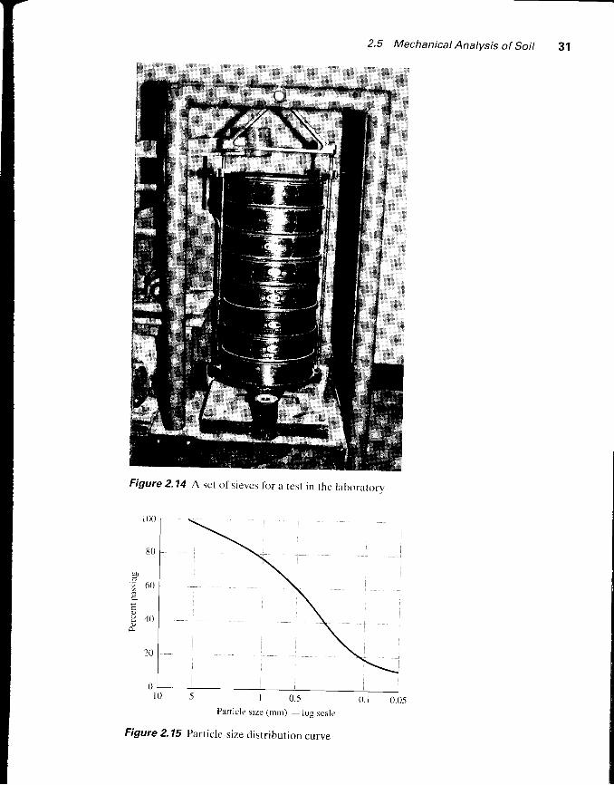
Sieve analysis consists of shaking the soir sampre through a set of sieves that haveprogressively smaller openings. U.S. standarcl i icve nu.i"., and the sizes of open_ings are given in Table 2.-5.The sicves used for soir analysis are generally 203 mm (g in.) in diameter. Toconduct a sieve anarysis, one must l irst ovJn-dry t 'he soil oni th"n break all lumpsinto small particles. The soil is then shaken through a stack of sieves with openingsof decreasing size from top to bottom (a pan is pliced below the stack). Figure 2.r4shows a set of sieves in a shaker used for conducting the test in the raboratory. Thesmallest-size sieve that should be used for this type of test is the U.S. No. 200 sieve.After the soil is shaken, the mass of soir retained on each sieve is determined. whencohesive soils are analyzecr, breaking the lumps into individual particles may bediff icult. In rhis case, rhe soil may bJmixed with water to-;l; a slurry and thenwashed through the sieves' Portions retained on each sieve are collected separatelyand oven-dried before the mass retained on each sieve is measured.
1. Determine the mass of soil retained on each sieve (i.e., Mr, Mz, . . . M,)and inthe pan (i.e., M,,).2 . D e t e r m i n e t h e t o t a l m a s s o f t h e s o i l : M t + M 2 + . . . + M , t . . . * M , + M e :
Chapter 2 Origin of Soil and Grain Size
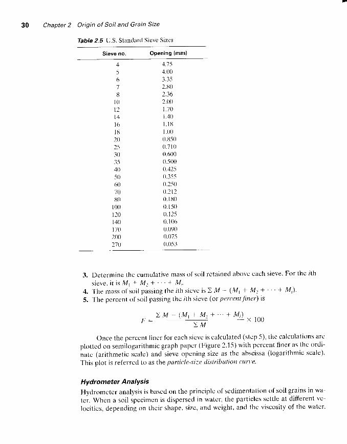
Table 2.5 U.S. Standard Sieve Sizes
Sieve no. Opening (mml
456'7
t5
I 01 2l 4l 6l lJ2025303-540-s06070u0
100120140no2002'70
4.754.003.352.130z.-1r)
2.(\')1 .101 .40t . l u1 .000.8-500 .71 00.6000.5(x)0.4250.35-50.2-500 .2 t20 . Iu00 . I 5 00 .1 250 . I060.0900.07-50.053
4.5.
Determine the cumulative mass of soil retained above cach sieve. For the ith
s ieve , i t i s M , + Mz* ' " * M i .The masso f so i l pass ing the i t h s i evc i s> M - (M t + Mz* " ' + M) .
The percent of soil passing thc lth sieve (or percent Jiner) ts
F ' _ > M - ( M t + M 2 + " ' + M , ) x r c o
> M
Once the percent f incr for each sieve is calculated (step 5), the calculations are
plotted on semilogarithmic graph paper (Figure 2.15) with percent f iner as the ordi-
nate (arithmetic scale) and sieve opening size as the abscissa (logarithmic scale).
This plot is referred to as the particle-siz,e distrihution curve-
Hydrometer Analysis
Hydrometer analysis is based on the principle of sedimentation of soil grains in wa-
ter. When a soil specimen is dispersed in water, the particles settle at different ve-
locities, depending on their shape, size, and weight, and the viscosity of the water.
2.5 Mechanicat Analysis of Soil 31
E
Figure 2.14 A set of sievcs lbr a test in thc laborarorv
particle size (rnnr) _ log scale
Figure 2.15 Particle-size distribution curve
l 0 .5
32 Chapter 2 Origin of Soil and Grain Size
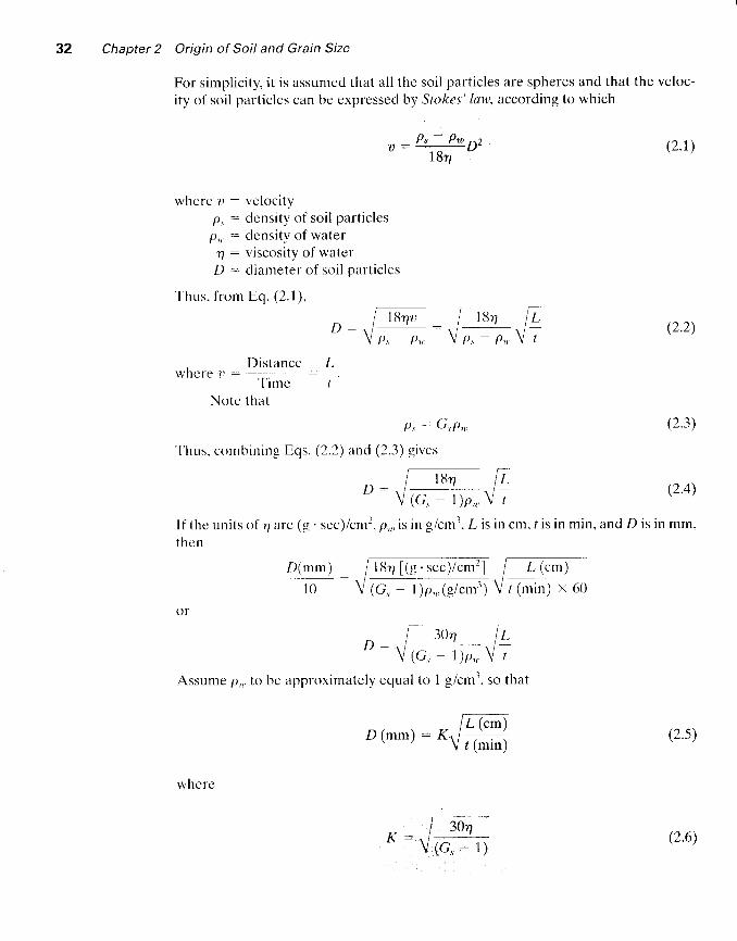
For simplicity, it is assumed that all the soil particles are spheres and that the veloc-
ity of soil particles can be expressed by Stokes' law, according to which
p, - p1n pzu :
r 8 T
where u : velocityp, : density of soil particlesp,,, : dcnsity of water
4 : viscosity of waterD : diameter of soil particles
Thus, f rom Eq. (2. l ) ,
(2.r)
D :
D is lancc Lwhcre r -
T ime tNote that
()r
t-- 3(\" fL.D : V r " . . - t l , V ;
Assume p,,. to bc approximately cqual to 1 g/cm3, so that
P , : G ,P , , ,
Thus. combining Eqs. (2.2) and (2.3) gives
(2.3)
(2.4)
I l ' the uni ts of 4 are (g ' sec) /cm2, p, , , is in g icmr, L is in cm, t is in min, and D is in mm,thelr
-ttr'r [(e.r".y.ff] T llc )
(C, - l )1 , , , .1g /cm' ,1 V / (n i 'n ) \ 60D(_TI') :
l 0
(2.2)
/ 7 5 \D ( m m ) : 6L (cm)
r (min)
3oa(G, - 1)
where
(2.6)
-
2.5 Mechanical Analvsis of Soil 33
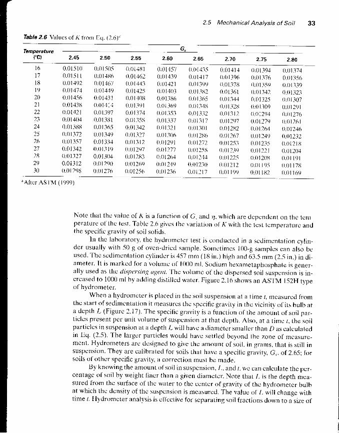
Table 2.6 Values of K tiom Eq. (2.6),'
c.Temperature('c) 2.45 2.60 2.70 2.75 2.80
1 67718l 9202122L-)
24252627282930
0.01510 0.01-5050 .01511 0 .014 rJ60.01492 0.0146l0.01474 0.014490.014,56 0.014310.01438 0.014140.01421 0.013970.01 404 0.01 3[i I0 .013u8 0.01 36-50.01372 0.013490.01 3.57 0.01 3340.01342 0.0 l3 l90.01327 0.013040 .01312 0 .012900.01298 0.01276
0.01481 0.014-570.01462 0.014390.01443 0.014210.01425 0.014030.0140n 0.0I 3860.0 1 39 1 0.01 3690.01374 0.013530.0 I 1.513 0.0I 3370.01342 0.0I3210.01327 0.01 3060 .01312 0 .012910.0t29 ' / 0 .012770.012133 0.012610.01269 0.012490.012-56 0.01236
0.0143.5 0.0141,10.01 4 17 0.01 3960.0I 399 0.0 I 3780.0 13u2 0.0136 10.0 I 36-s 0.013440.01 348 0.0 I 3280.01 332 0.01 3 1 20.013t7 0.012970.01 301 0.01 2u20.012116 0.012670.0t272 0.0t2530.0I 2.sti 0.0 I 239o.ol244 0.012250.01230 0.012120 .01217 0 .01199
0.01394 0.0137 40.01376 0.013560.01 359 0.01 3390.01342 0.013230.01 325 0.01 3070.01309 0.012910.0t294 0.012760.0t279 0.0t2610.01264 0.012460.01249 0.0t2320.0123-5 0.0121t30.01221 0.012040 .0 t201J 0 .011910.01 19-s 0.01 17u0 .01 l t t 2 0 .01 t69
"After ASTM (1999)
Note that the value of K is a function of G, and 4, which are depenclent on the tem-perature of the test. Table 2.6 gives thc variation o1'K with the test tempcrature andthe specific gravity of soil solids.
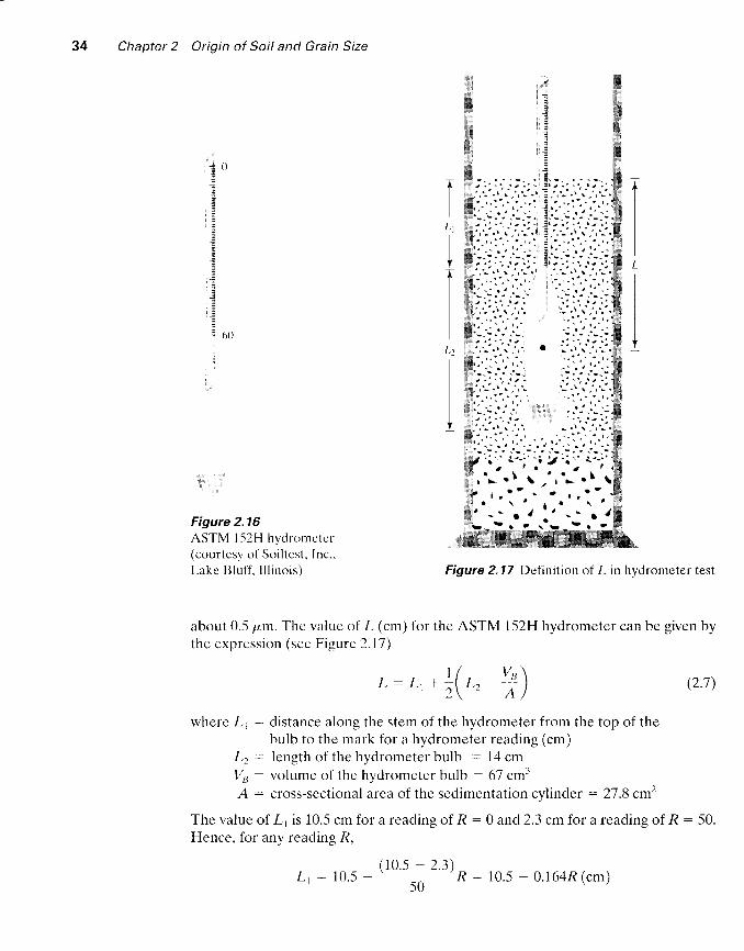
ln the laboratory, the hydrometcr test is concluctccl in a sedimentation cylin-der usually with 50 g of oven-driccl sample. Sometimes 100-g samples can also beused. The sedimentat ion cy l indcr is 4-57 mm (18 in. ) h igh and 63. ,5 mm (2.-5 in . ) in d i -ameter. It is marked for a volume of 1000 ml. Sodium hexametaphosphate is gener-af ly used as the dispersing ugent. The volumc of the clispersed soil suspension is in-creased to 1000 mlby adding d is t i l led water . F igure 2.16 shows an ASTM l52H tvpeof hydrometer.
When a hydrometer is placed in the soil suspension at a time t, measured fromthe start of sedimentation it measures the specific gravity in the vicinity of its bulb ata depth L (Figure 2.17).The specific gravity is a function of the amount of soil par-ticles present per unit volume of suspension at that depth. Also, at a time r, the soilparticles in suspension at a depth L wil l have a diameter smaller than D as calculatedin Eq. (2.,5). The larger particles would have settred beyond the zone of measure-ment. Hydrometers are designed to give the amount of soil, in grams, that is sti l l insuspension. They are calibrated for soils that have a specific gravity, G., of 2.65; forsoils of other specific gravity, a correction must be made.
By knowing the amount of soil in suspension. L, and /, we can calculate the per-centage of soil by weight f iner than a given diameter. Note that L is the depth mea-sured from the surface of the water to the center of gravity of the hydrometer bulbat which the density of the suspension is measured. The value of L wil l change withtime /. Hydrometer analysis is effective for separating soil fractions down to a size of
Chapter 2 Origin of Soil and Grain Size
Figure 2.16ASTM l52H hydronrc te r(c ( )u r tcs ) t r l So i l t cs t . Inc . .Lakc Btu l l ' . I l l i no is ) Figure 2.17 Definition o1 /- in hydrometer test
about 0.-5 pm. The value of L (cm) 1or the ASTM l52H hydrometer can be given bythc expression (see Figure 2.17)
(2.1)
where L, : distance along the stem of the hydrometer from the top of thebulb to the mark for a hydrometer reading (cm)
L, : length of the hydrometer bulb : 14 cmI/a : volume of the hydromcter bulb : 67 cml-A : cross-sectional area of the sedimentation cylind er : 27 .8 cm2
The value of l,, is 10.-5 cm for a reading of R : 0 and 2.3 cm for a reading of R : 50.Hence, for any reading R,
iI
j 6 0
L
IL l
I
L 1
L: Lr . +( t , +)
r r0.5 - 2.3)Lr : 10.5 -
-R : 10.5 - 0.164R (cm)
2.5 Mechanical Analysis of Soit
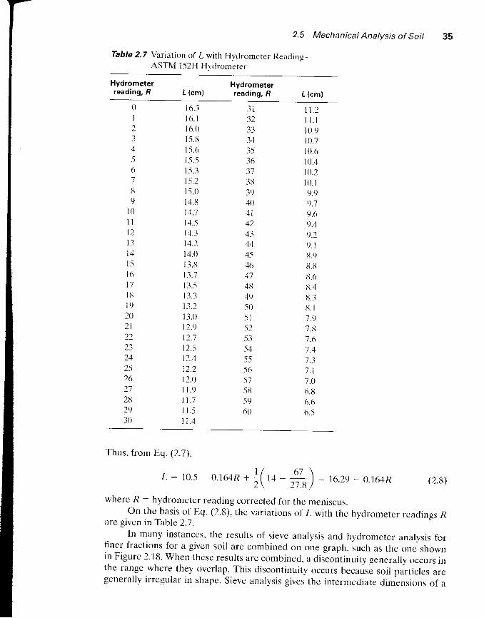
Table 2.7 Variation of L with Hyclrometer Reading -ASTM 152H Hvdrometer
35
Hydrometerreading, fl I (cml
Hydrometerreading, fr L (cml
UI2345678r)
l 0l lt 2l 3t 4l 5l 6T 7l 8l 9202 l22L- )
1 /,1
2526272132930
16 .31 6 . 1i6.0l-5.tt1 .5.61.5.5l -5.315.215 .014 .8I4.l14..51,1.314.2r4 .0l3. t tt3.7I3. -5I - ) . - )
13.213 .0t2 .912 .712.-512.4t2 .212.0I 1 . 9t1 .7I l . -sI 1 . 4
3 1
33-)4
3-536373839404 l424-1
444546414tt4950. ) l
521.1
-s45-5-5657-5u-s960
t I . zl l . l10 .9I0 .710 .610 .4to.2I 0 . l9 .99.79.6L).4
9.29. 18.9ti. tt6 .68.4u.3,1. I7 .97.81.67.4
1 . 17.06.ttb .o6.-5
Thus, from Ecl. (2.1),
(2.8)
where R : hydrometer reading corrected for the meniscus.on the basis of Eq. (2.8), the variations of L with the hydrometer readinss R
are given in Table 2.7 .In many instances, the results of sieve analysis and hydrometer analysis for
finer fractions for a given soil are combined on one graph, iuch as the one shownin Figure 2.18. When these results are combined, a discontinuity generally occurs inthe range where they overlap. This discontinuity occurs UecausJ soil particles aregenerally irregular in shape. Sieve analysis gives thc intermediate diminsions of a
L - t o . . s l s a q n + l / 6 7 \
2 ( 1 4 -
" - . n ) :
t o , z v 0 . 1 6 4 R
36 Chapter 2 Origin of Soil and Grain Size
Unified classification
Sand Silt and clay
Sieve Sieve analysis Hydroneter analysis
no. l0 16 30 40 60 100 200
o Sieve analysist Hydrorneter analysis
(,'5 2 I 0s
l],1,,.1i'.,i l, i., '",,,,\ '#"t""""t 0(x)2 000r
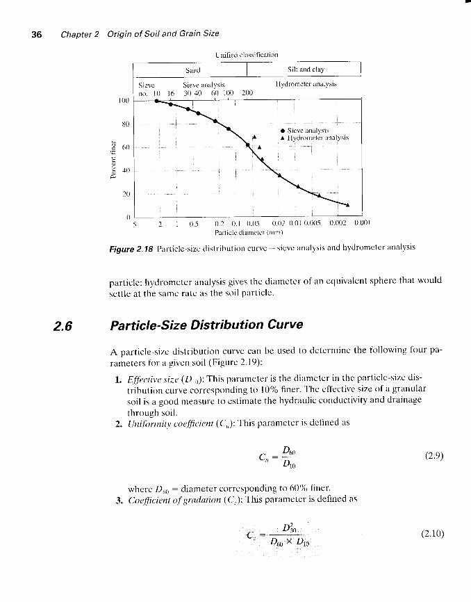
Figure 2.18 Parlicle-size distribution curvc - sicve analysis and hydrometer analysis
particlet hydrometer analysis gives the diametcr of an equivtl lent sphere that would
sct t le at the samc ratc as the soi l par t ic lc .
2.6 Particle'Size Distribution Curve
A particle-size clistribution curve can be used to determine the following four pa-
rameters for a g ivcn soi l (F igurc 2.19) :
l. 8.fl 'ective siz,e (D11): This parameter is the diameter in the particle-sizc dis-
tribution curve corresponding to l0% Iiner. The effective size of a granular
soil is a good measure to estimate the hydraulic conductivity and drainage
through soi l .2. IJniformity ctte.ft'icient (C,,): This parameter is defincd as
100
t s o o
d + r ,
c, : le es)..tt Dn
where D66 : diameter corresponding to 60% finer'
3. Coefficient of gradation (C ,): This parameter is defined as
D4". . :#; (2.10)

8075
b 6 0
Egol +o
302520
t 0
( ,
2.6 Particle-Size Distribution Curve
l0 5 | 0. -5
Part ic le s izc (mnr)
Figure 2.19 Detinition of D7., Dnu. Dtr l)2., and D1,,
Sorting coefficient (s,,): This parameter is anothe r measure of uniformitv and isgenerally encountered in geologic works and expressed as
(2.r1)
The sorting coefficient is not frequently used as a parameter by geotechnicalengineers.
The percentages of gravel, sand, silt, and clay-size particles present in a soil canbe obtained from the particle-size distribution curve. As an example, we wil l use theparticle-size distribution curve shown in Figure 2. lg to determine the gravel, sand,silt, and clay-size particles as follows (according to the Unified Soil ClassificationSystem - see Table 2.3):
Size (mm) lo tiner
6;S , , :V r ^
76.24.750.075
10010062U
100 - 100 :0% g rave l100 - 62: 38% sand62 - 0: 620/o sllt and clay
The particle-size distribution curve shows not only the range of particle sizespresent in a soil, but also the type of distribution of various-size pirticlei. Such typesof distributions are demonstrated in Figure 2.20. Curve I represents a type of soii in

38 Chapter 2 Origin of Soil and Grain Size
2 | 0.-5 0.2 0. | 0.05 0.02 0.0 | 0.005
Ptn ic lc d iamcter (n l l r )
Figure 2.20 Dilferent types ol pirrticle-sizc distribution curves
which most of the soil grains zrrc the same size. This is called poorly gradad soll.
Curve II represents a soil in which the particle sizes are distributed over a wide range,
termed well grtrt led. A well-gracled soil has a uniformity coefficient greater than about
4 for gravcls and 6 for sands, and zr coefficicnt ofgradation bctween 1 and 3 (for grav-
els and sands). A soil might have a combination of two or morc uniformly graded frac-
tions. Curve l l l reprcsents such a soil. ' Ihis type ol'soil is tcrmed gap grudcd.
Example 2.1
Following are the results of a sieve analysis. Make the necessary calculations and
draw a particle-size distribution curve.
Mass of soil retainedU.S. sieve size on each sieve {gl
0406089
140t z t
21.056T2
Solutionitr"hff.*i"g table can now be prepared.
100
H 6i)
E
b 4 0o
20
41020406080
100200Pan

2.6 Particle-Size Distribution Curve 39
u.s.sieve
( 1 )
MassOpening retained on
{mm} each sieve (gl{2t {3}
Cumulative massretained aboveeach sieve (gt
{4)
Percentfinero
t5)AT
1020406080
100200Pan
4. tJ
2^000.8500.4250.2500.1800.1500.075
0406089
140\2227056I2
10094.586.374,154.93E.19.31.70
00 + 4 0 : 4 0
4 0 + 6 0 = 1 0 01 0 0 + 8 9 : 1 8 9189+I40-329329+122-45145I+210=6616 6 1 + 5 6 = 7 1 77 1 7 + 1 2 : 7 2 9 : 2 M
. > M - col.4 x 1oo: Z*U * ,uo729
The particle-size distribution curve is shown in Fisure 2.21.
t0 5 3 I 0..5 0.3Particlc sizc (mrn)
Figure 2.21 Particle-size distribution curve
2 M
100
b 6 ( )E
I +tl
t 0
(, 1)111 = fl.15 n.'t,t
Example 2.2
For the particle-size distribution curve shown in Figure 2.21, determinee. Dro,D.ro, and Doob. Uniformity coefficient, C,c. Coefficient of gradation, C.
40 Chapter 2 Origin of Soil and Grain Size
$olutiona. From Figwe2.27,
Dro : 0'15 mm
D3s : 0.17 mm
D6r,: 0.27 mmD^,, O27: ttb . c , , : n : n s - . _
' ':#o*:#ffib-o'71
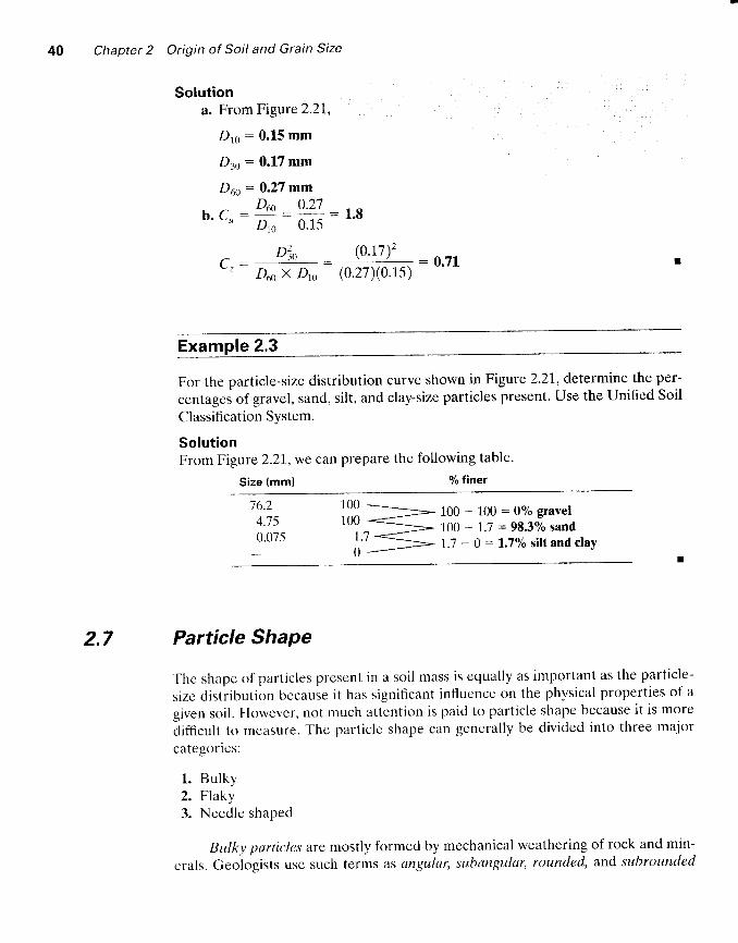
For the particle-size distribution curve shown in Figure 2'21, determine the per-
centages of gravel, sand, silt, and clay-size particles present. Use the Unified Soil
Classification System.
SolutionFrom Figure 2.27,we can prepare the following table.
Size (mml % f iner,
76.24.750.075
l[]3,= 100 * 100 = 0o/o Eravel100 * 1.7 * 98.3olo sand1.7 - 0 = l.7o/o silt and clay
2.7 Particle Shape
T'hc shape of particles present in a soil mass is equally as important as the particle-
sizc distribution because it has significant influence on the physical properties of a
given soil. However, not much attention is paid to particle shape because it is more
difhcult to meersure. The particle shape can generally be divided into three major
categories:
l . Bulky2. Flaky3. Needle shaped
BuLky particles are mostly formed by mechanical weathering of rock and min-
erals. Geologists use such terms as angular, subangular' rounded, and subrounded
2.7 Particle Shape 41
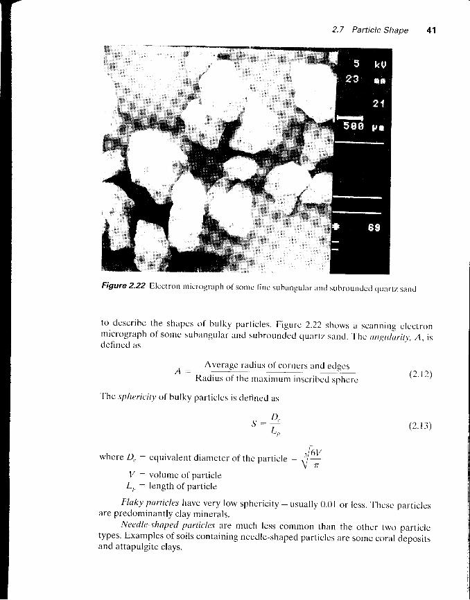
Figure 2.22 Eleclrttn micrograplr ol 'sontc Iinc subar-rgular and subroundccl quartz sand
to descr ibe the shapes of bulky par t ic les. F igure 2.22 shows a scanl ins c lect ronmicrograph of some subangular ancl subroundecl quartz sarrd. ' l-hc
ungtiluritv, A, isdcfincd as
o : AM$9 t9'dillolggMtt a'd edscsRadius ol'the maximu- inr.t itre.t rph"t.
The sphericity oi bulky particles is definecl as
(2 .12)
__ D,. t -
L
whcre Q, - equivalent diameter of the particle -
I/ - volume of particleL,, : length of particle
(2 . r 3)
Flaky purticles have very low sphericity - usually 0.01 or less. Thesc particlesare predominantly clay minerals.
Needle-shaped particles are much less common than thc other two oarticletypes. Examples of soils containing needle-shaped particles arc some coral depositsand attapulgite clays.
6VT
42 Chapter 2 Origin of Soil and Grain Size
2.8 Summary
In this chapter, we discussed the rock cycle, the origin of soil by weathering, the par-
ticle-size distribution in a soil mass, the shape of particles, and clay minerals. Some
important points include the following:
1. Rocks can be classified into three basic categories: (a) igneous, (b) sedimen-
tary, and (c) metamorphic.2. Soils are formed by chemical and mechanical weathering of rocks.
3. Based on the size of the soil particles, soil can be classified as gravel, sand, silt,
or clay.4. Clays are mostly f lake-shaped microscopic and submicroscopic particles of
mica, clay minerals, and other minerals.5. Clay minerals are complex aluminum sil icates that develop plasticity when
mixed with a l imited amount of water.6. Mechanical analysis is a process for determining the size range of particles
present in a soil mass. Sieve analysis and hydrometer analysis are two tests
used in the mcchanical analysis of soil.
Problems2.1 For a soil with Do,, : 0.42 mm, D11y : 0.21 mm, and D',, : 0.16 mm, calculate
thc uniformity coefficient and the coeflicient of gradation.
2.2 Rcpe at Problem 2.1 with the following values: D 111 : 0.27 mm' Dj1, : 0.41
mm, and 1),,,, : 0.l l l mm.2.3 Following arc the results of a sievc analysis:
U.s. sieve no. tn""'"h'liff:",Ti'
4 t )l 0 1 8 . 520 53.240 90..s60 81 .8
100 92.2200 58.5Pan 26.5
a. Determine the percent finer than each sieve size and plot a grain-size dis-
tribution curve.b. Determine Dy,, D.u. and D611 from the grain-size distribution curve.
c. Calculate the uniformity coeflicient C,,.d. Calculate the coefficient of gradation, C-.
2.4 Repeat Problem 2.3 with the following results of a sieve analysis.

Problems
Mass of soil retainedU.S. sieve no. on each sieve (g)
1l 0204t)60
100200Pan
041.25.5.180.t)9 l . 660.-s3-5.621.5
Repeat Problem 2.3 with the following results for a sieve analysis.
Mass of soil retainedU.S. sieve no. on each sieve (gl
0(.,
20 .119 .5
2I0. -5135.622.7I .5.-5
l - 1 . - )
Thc particle-size characteristics of a soil are given in this table. Draw thepart ic le-s ize d is t r ibut ion curvc.
Size (mm) Percent f iner
('t.4250.0330 .0180.0I0.(x)620.00350.001 r.i0 .00I
Determinc the percentages of gravel, sand, silt, and clay:a. According to the USDA system.b. According to the AASHTO system.Repeat Problem 2.6 with the following data:
Size (mm) Percent f iner
0.4250 .10.0520.020 .010.0040.001
46
l 0204060
l(x)200Pan
l ( x )90t307o60504035
2.7
r0092846246J L
22
Chapter 2 Origin of Soil and Grain Size
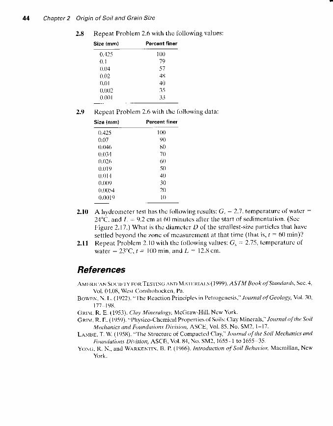
2.8 Repeat Problem 2.6 with the following values:
Size (mm) Percent f iner
0.4250 .10.040.020.010.0020.001
100195748403533
2.9 Repeat Problem 2.6 with the following data:
Size (mm) Percent f iner
0.4250.070.0460.0340.0260 .0190 .0140.0090.(x)540.(x) t 9
2.10 A hydromcter test has the following results: G, : 2.'7 , tempcrature of water :
24"C. and l, : 9.2 cm at 60 minutes after the start of sedimentation. (See
Figure 2.17.) What is the diameter D of the smallest-size particles that have
settled beyond the zone of measurement at that t ime (that is, r : 60 min) /
2. l l Repeat Problem 2.10 wi th the fo l lowing values: G, :2.75, temperature of
watcr : 23"C. t : 100 min. and L : 12.u cm.
ReferencesAvenrr ' ,qN S<rc're ly rron' l 'Es'r ' rNc; nNo Mxr' tr t<r,qn ( 1999). ASTM Book ofStandards, Sec.4,
Vol. 04.08. West Conshohocken, Pa.
BcrwEN. N. L. ( 1922). "The Reaction Principles in Petrogenesis," Journal of Geology, Vol. 30,
l7'7 -198.
Gnrv, R. E. (1953). Cluy Mineralogy, McGraw-Hil l , New York.
Gnrv, R. E. ( l9-59). "Physico-Chemical Propert ies of Soi ls: Clay Minerals," Journal of the Soil
Mechanics and Foundations Division, ASCE. Vol. 85, No. SM2, 1-17.
LnMsE, T. W. ( 1958). "The Structure of Compacted CIay," Journal of the Soil Mechanics and
Rtundations Division, ASCE, Vol.84, No. SM2, 1655-1 to 16-55-35.
YoNc;, R. N., and WanreNttN, B. P. (1966). Introduction of Soi l Behavior, Macmil lan, New
York.
10090807060-50403020l 0
Related Documents