G. Vereb Geometrical optics, Microscopy Transmission (conventional light) microscopy Fluorescence microscopy Electron microscopy (transmission, scanning) György Vereb Department of Biophysics and Cell Biology, University of Debrecen Textbook: 107-109 388-397 398-399 605-607 Interconnection with other lectures: Lect. 3. Application of fluorescence Lect. 6. Lasers Lect. 22. The human eye Lect. 24. Flow cytometry, confocal laser scanning microscopy Lect. 27. Modern microscopic techniques

Welcome message from author
This document is posted to help you gain knowledge. Please leave a comment to let me know what you think about it! Share it to your friends and learn new things together.
Transcript

G. Vereb
Geometrical optics, Microscopy
Transmission (conventional light) microscopy
Fluorescence microscopy
Electron microscopy (transmission, scanning)
György Vereb
Department of Biophysics and Cell Biology, University of Debrecen
Textbook:
107-109
388-397
398-399
605-607
Interconnection with other lectures:
Lect. 3. Application of fluorescence
Lect. 6. Lasers
Lect. 22. The human eye
Lect. 24. Flow cytometry, confocal laser scanning microscopy
Lect. 27. Modern microscopic techniques

G. Vereb
Major points for discussion
• Geometrical optics, Snell’s law
• Image formation by simple lenses
• Lens aberrations
• Image formation in the compound microscope
• Transmission light microscopy
• Fluorescence microscopy
• Scanning vs. full field imaging
• Resolution
• Electron microscopy (transmission, scanning)
Why bother?
• Foundations for understanding how optical devices used in medicine
work• Usage of the microscope (anatomy, pathology, microbiology, haematology)
• Otoscope, ophthalmoscope, endoscopes
• Biomedical research
• Foundations for ophthalmology

G. Vereb
121
2
sin
sin
cin
r c
Snell – Descartes law
BASIC PRINCIPLES OF GEOMETRICAL OPTICS
incident
light ray
refracted
light ray
reflected
light ray
normal to
surface
Medium 2
Medium 1
!
In this example, medium 2 is
optically denser than medium 1,
and therefore the speed of light
(c2) in it, is lesser. Consequently,
its index of refraction relative to
medium 1 is greater than 1.

G. Vereb
!
Focusing
F
F
focal point
Optical axis
Collimation
Image formation of thin lenses I
21
11)1(
1
RRn
f
The more curved the lens, the closer
it focuses
→ higher refractive power:
fdiopterD
1)(
Unit: 1/m

G. Vereb
Image formation of thin lenses II !
oif
111

G. Vereb
Image formation of real (thick) lenses
21
2
21
)1(11)1(
1
RR
d
n
n
RRn
f
Major planes
object
image
Outlook

G. Vereb
Healthy eye
• Images of both close and distant objects are formed
on the retina
Short-sighted (near-sighted) eye
(myopia)
• The axis of the eye is longer than physiological, or
its minimal refractive power is still too high
• A sharp image of the close object is formed on the
retina, but the image of a distant object is formed in
front of the retina, so it is smeared on the retina
• Correction: with a diverging lens
Far-sighted eye (hypermetropia)
• The axis of the lens is shorter than physiological, or
its maximal refractive power is not high enough
• A sharp image of the distant object is formed on the
retina, but the image of a close object is formed
behind the retina, so it is smeared on the retina
• Correction: with a converging lens
!Image formation by the human eye and its most frequent defects

G. Vereb
LENS ABERRATIONS
Monochromatic Chromatic
Spherical aberration
Coma
Astigmatism
Field curvature
Manifestiations:
-Longitudinal
-Lateral
Astigmatism
Distortion
Also with perfect, symmetric lenses
With imperfect lenses
cause: physical thickness →
smaller refractive power closer to
the centre
cause: refractive index
depends on wavelength
→ red is focussed farther
!

G. Vereb
Distortion
object “pincushion” “barrel”
•Does not affect the sharpness of the image
•Magnification is different in the center than at the edges
5*

G. Vereb
•Light rays are refracted (bent)
•Refractive index depends on wavelength
•Red is refracted to the smallest extet, violet the most
•Hence white or polychromatic light is separated into
components of different wavelenghts
dispersion
Chromatic aberrations!

G. Vereb
• Monochromatic aberrations
Also with perfect lenses, cause: physical thickness → smaller refractive power
closer to the centre
– Spherical aberration: for parallel rays, focal point is closer for rays further
away from the optical axis
– Coma: divergent rays at large angles, point source off the optical axis
– Astigmatism: divergent rays at small angles, point source off the optical axis
– Field curvature: focal sphere instead of focal plane, related to astigmatism
With imperfect lenses
– Distorsion
– Astigmatism: the lens is cylindrical (has different refractive power along at
least two axes, also seen when rays are parallel to the optical axis
• Chromatic aberration
Also with perfect lenses, cause: refractive index decreases with increasing
wavelength. Manifestations:
– Longitudinal chromatic aberration
– Lateral chromatic aberration
LENS ABERRATIONS

G. Vereb
Anton Van Leeuwenhoek’s
Simple Microscope - 1670
Outlook

G. Vereb
Magnification: product of individual magnifications
Mi= I / O = i / o
Image formation in the conventional light microscope
compound microscope
objective and ocular
magnified, inverted, virtual image
F12F1
2F1 F2
!
F2
F1

G. Vereb
F1
2F1
2F1 F2
Film
CCD camera chip
Variations for
increasing contrast:
dark field
phase contrast
polarization
Taking the image in the conventional (full field) light
microscope!

G. Vereb
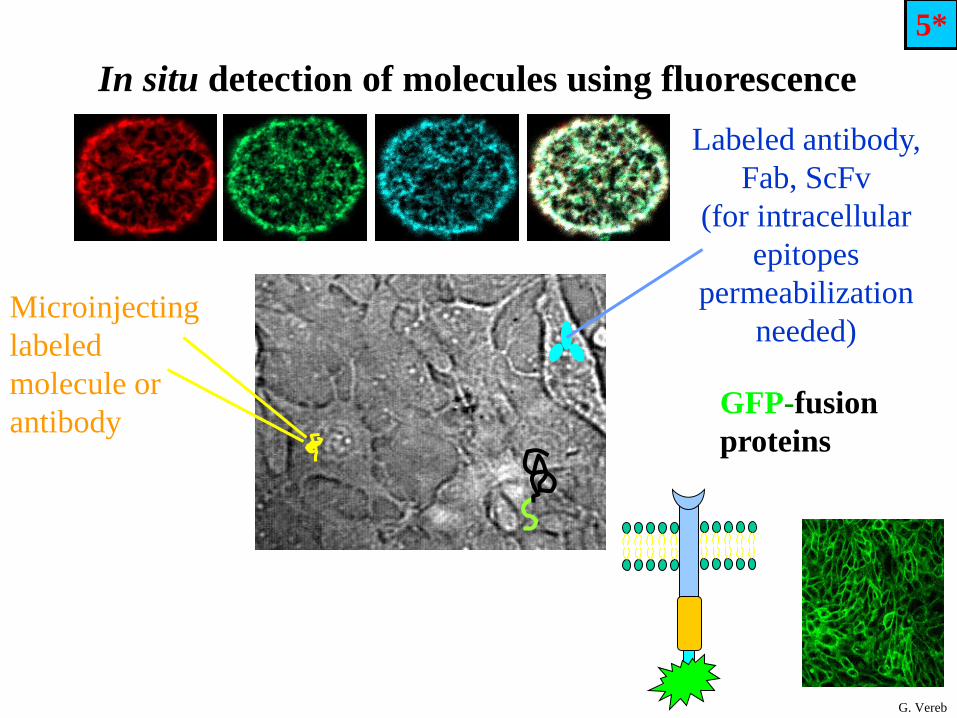
Application of fluorescence in the microscope
Contrast enhancement
•Against the dark background, every photon represents a 100%
increase of light intensity
•A Fluorescent labels can be bound to virtually any specific
molecule
•A Most fluorescent labels cause no harm to living cells and are
compatible with vital processes
!
G. Vereb
GFP-fusion
proteins
Microinjecting
labeled
molecule or
antibody
Labeled antibody,
Fab, ScFv
(for intracellular
epitopes
permeabilization
needed)
In situ detection of molecules using fluorescence
5*

G. Vereb
Sketch of the (epi)fluorescence microscope
ocular
objective
dichroic
mirror
observer
Condenser
lens
emission
filter
Excitation
filter
sample
lamp
!

G. Vereb
Imaging modalities
I. Full field
Illumination: full field (all the area that is observed)
Detection: full field, by
eye,
SLR camera (film),
electronic camera
II. Scanning
Illumination : point (i.e. laser source)
Detection : from point
without regard to where the photons arrive
onto the surface of the detector
e.g. Photomultiplier tube (PMT),
avalanche photodiode (APD)
Scanning : stage
laser beam (with moving mirrors)
!
!
5*

G. Vereb
x y
PMT
SCANNINGOutlook

G. Vereb
x, the limit of resolution (in the image plane), is independent of
the magnification of the lens
Limit of resolution(condition of perceiving the image of two points as two spots)
x
!
5*
G. Vereb
a
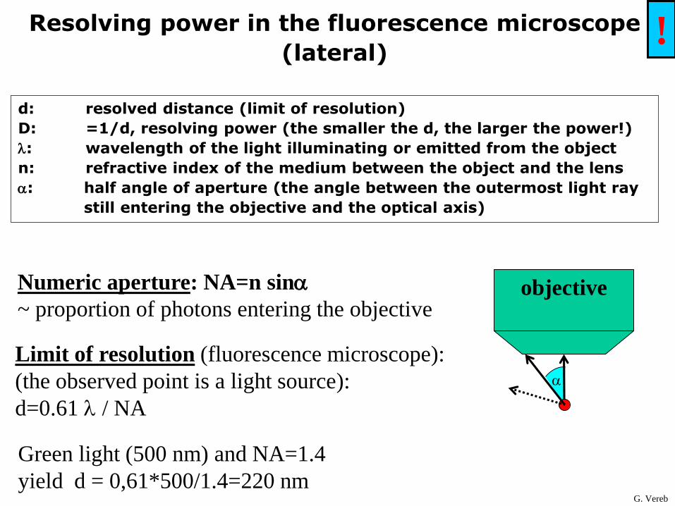
Resolving power in the fluorescence microscope
(lateral)
Limit of resolution (fluorescence microscope):
(the observed point is a light source):
d=0.61 l / NA
Numeric aperture: NA=n sina
~ proportion of photons entering the objectiveobjective
d: resolved distance (limit of resolution)
D: =1/d, resolving power (the smaller the d, the larger the power!)
l: wavelength of the light illuminating or emitted from the object
n: refractive index of the medium between the object and the lens
a: half angle of aperture (the angle between the outermost light ray
still entering the objective and the optical axis)
!
Green light (500 nm) and NA=1.4
yield d = 0,61*500/1.4=220 nm

G. Vereb
a
Resolving power (lateral)
Transmission (conventional)
light microscope
Limit of resolution:
d= l / (NAobjective +NAcondenser) → d ≈ l / 2NA
Numeric aperture: NA=n sina
~ proportion of photons entering the objectiveobjective
condenser
d: resolved distance (limit of resolution)
D: =1/d, resolving power (the smaller the d, the larger the power!)
l: wavelength of the light illuminating or emitted from the object
n: refractive index of the medium between the object and the lens
a: half angle of aperture (the angle between the outermost light ray
still entering the objective and the optical axis)
!
Increasing resolution:
Decrease λ (UV, X-ray, electron)
Increase NA
(n: immersion oil; α: large lens, close up)
G. Vereb
Electron Microscopy
Wave property of the electron is utilized
Transmission Electron Microscopy (TEM)
Scanning Electron Microscopy (SEM)
!

G. Vereb
Outlook
Outlook
Wavelength of the electron beam !
Wavelength (λ) of the electrons is determined by the
accelerating voltage (V)
Thus, very high voltages (up to 100 kV) are used to produce
small values of λ (<0.005 nm)
(de Broglie, 1924)
λ = 0.1(150/V)0.5
λ =𝒉
𝒑=
𝒉
𝒎𝒗
Considering the relativistic increase of mass at high velocity:

G. Vereb
Interaction of the Electron Beam with the Sample
(TEM)
(SEM)!
!
5*
G. Vereb
In a transmission electron microscope, beams of electrons are
focussed using magnetic lenses.
Image formation follows the same principles as in
conventional transmission light microscopy (an interference
image is formed)
The resolving power produced is up to 500,000 times greater
than the human eye.
Because a vacuum is needed, tissue has to be specially
prepared, and living cells cannot be examined
Transmission Electron Microscope (TEM)
!

G. Vereb
Transmission Electron Microscope5*

G. Vereb
Mitochondria

G. Vereb
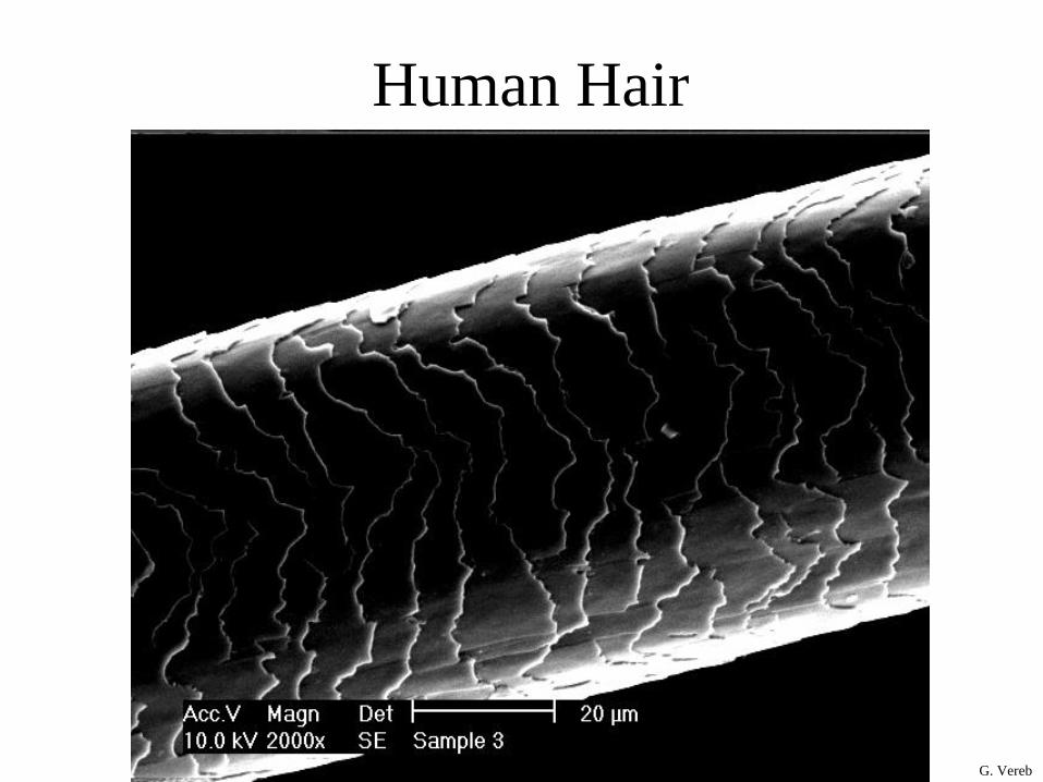
• An electron beam scans the surface of the specimen
• Secondary electrons are released from the surface, and collected by a special electron detector
• The secondary electron current is converted into an image, which appears on a computer screen and gives an impression of the outer shape of the specimen
• For better contrast, the surface can be covered with a material of high atomic number (eg. Os)
INFO: a few SEM devices detect the backscattered electrons, and not secondary electrons
Scanning Electron Microscope!

G. Vereb
Scanning Electron Microscope5*
G. Vereb
Human Hair

G. Vereb
Minimum equations:
121
2
sin
sin
cin
r c
21
11)1(
1
RRn
f
fdiopterD
1)(
advanced equations:
oif
111
D=1/d
NA=n sina d=0.61 l / NA
d= l / (NAobjective +NAcondenser) → d ≈ l / 2NA
!
Outlook
𝜆 =ℎ
𝑝=
ℎ
𝑚𝑣
minimum / basic information
for explanation / orientation purposes
5* To impress the examiner
Related Documents