GD&T GEOMETRICAL DIMENSIONING AND TOLERENCE

GEOMETRICAL DIMENSIONING AND TOLERENCE 1. Geometric dimensioning and tolerancing is an international language used on drawings to accurately describe.
Dec 18, 2015
Welcome message from author
This document is posted to help you gain knowledge. Please leave a comment to let me know what you think about it! Share it to your friends and learn new things together.
Transcript
GD&TGEOMETRICAL DIMENSIONING
AND TOLERENCE
GD&TOVERVIEW
1. Geometric dimensioning and tolerancing is an international language used on drawings to accurately describe a part. The language consists of a well-defined set of symbols, rules, definitions, and conventions that can be used to describe the size, form, orientation, and location tolerances of part features.
2. Geometric Dimensioning and Tolerancing (GD&T) is a language used on mechanical engineering drawings composed of symbols that are used to efficiently and accurately communicate geometry requirements for associated features on components and assemblies.
3. GD&T is, and has been, successfully used for many years in the automotive, aerospace, electronic and the commercial design and manufacturing industries.In today's modern and technically advanced design, engineering and manufacturing world, effective and accurate communication is required to ensure successful end products.

History of GD&T
Geometric Dimensioning and Tolerancing symbols have been in use since at least the turn of the century. GDT was especially important during the Second World War in relation to extremely high volume production of Liberty Ships, aircraft, and ground vehicles. The automotive industry, with its high volumes, has also benefited from GDT. The computer industry, in particular mass storage manufacturers, have used GDT extensively to increase their yields of high-volume and low-margin hard disk drives. However, as with most engineering and scientific methodologies, GDT was not rigorously established and documented until later in the twentieth century. The American National Standards Institute publication in 1982 of ANSI Y14.5M-1982 was a turning point in the rigorous, unambiguous standardization of the methodology.
ADVANTAGES
1. Standardized, international system.2. Provides a clear and concise technique for defining a
reference coordinate system (datum's) on a component or assembly to be used throughout the manufacturing and inspection processes.
3. Geometric dimensioning dramatically reduces the need for drawing notes to describe complex geometry requirements on a component or assembly by the use of standard symbology that accurately and quickly defines design, manufacturing and inspection requirements.
4. More flexibility, particularly for complex shapes.5. Eliminates the need for many notes.6. Based on the fit and function of a part or assembly.
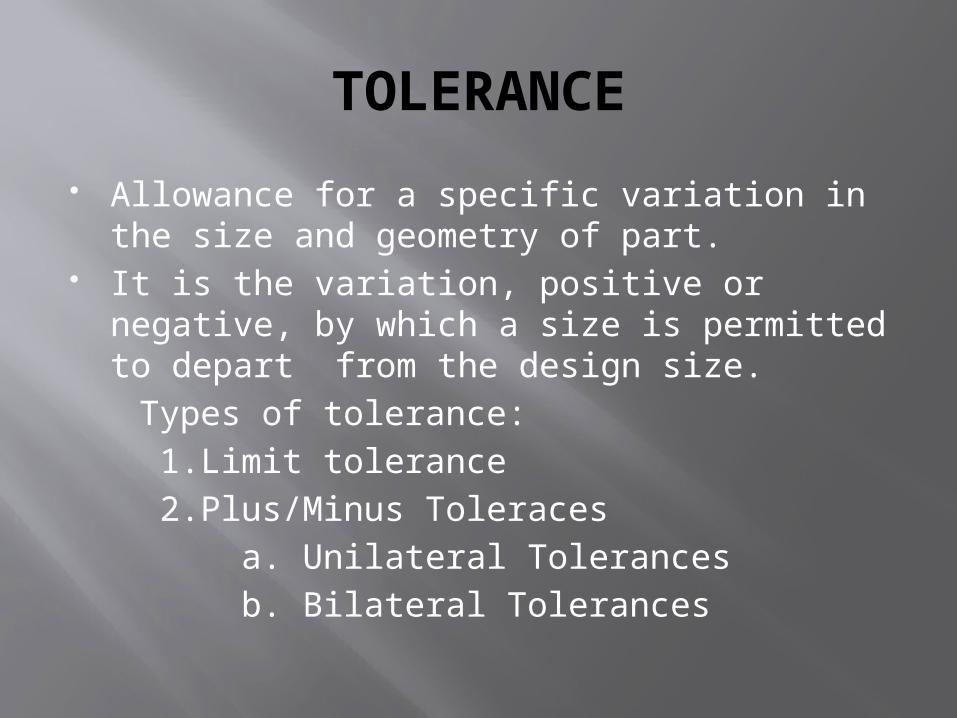
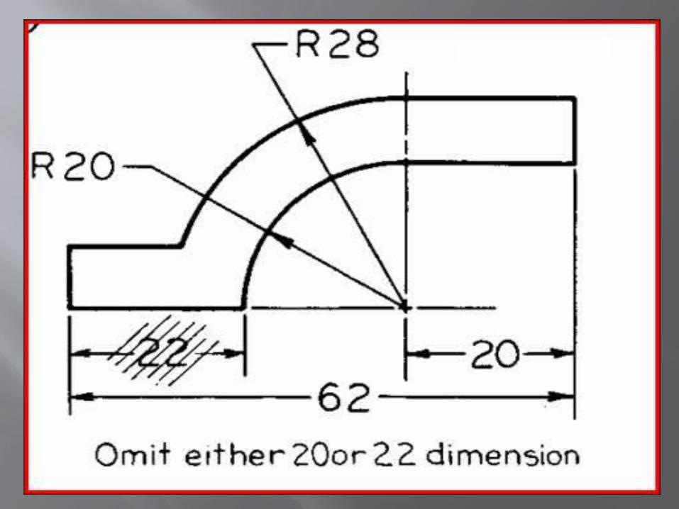
TOLERANCE
Allowance for a specific variation in the size and geometry of part.
It is the variation, positive or negative, by which a size is permitted to depart from the design size.
Types of tolerance: 1.Limit tolerance 2.Plus/Minus Toleraces a. Unilateral Tolerances b. Bilateral Tolerances
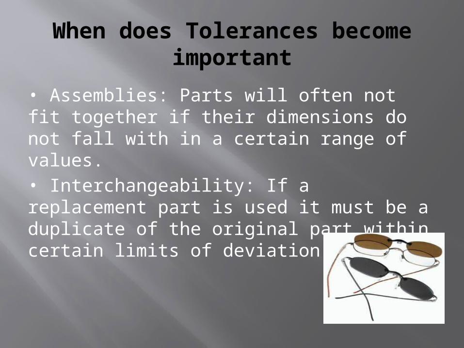
When does Tolerances become important
• Assemblies: Parts will often not fit together if their dimensions do not fall with in a certain range of values.• Interchangeability: If a replacement part is used it must be a duplicate of the original part within certain limits of deviation.
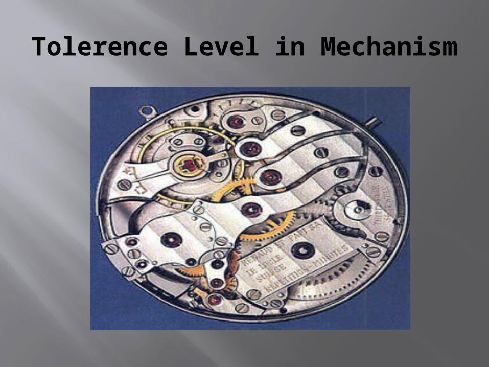
Tolerence Level in Mechanism
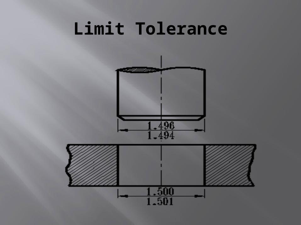
Limit Tolerance
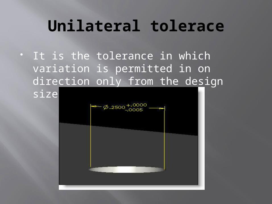
Unilateral tolerace
It is the tolerance in which variation is permitted in on direction only from the design size.
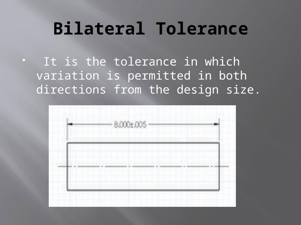
Bilateral Tolerance
It is the tolerance in which variation is permitted in both directions from the design size.
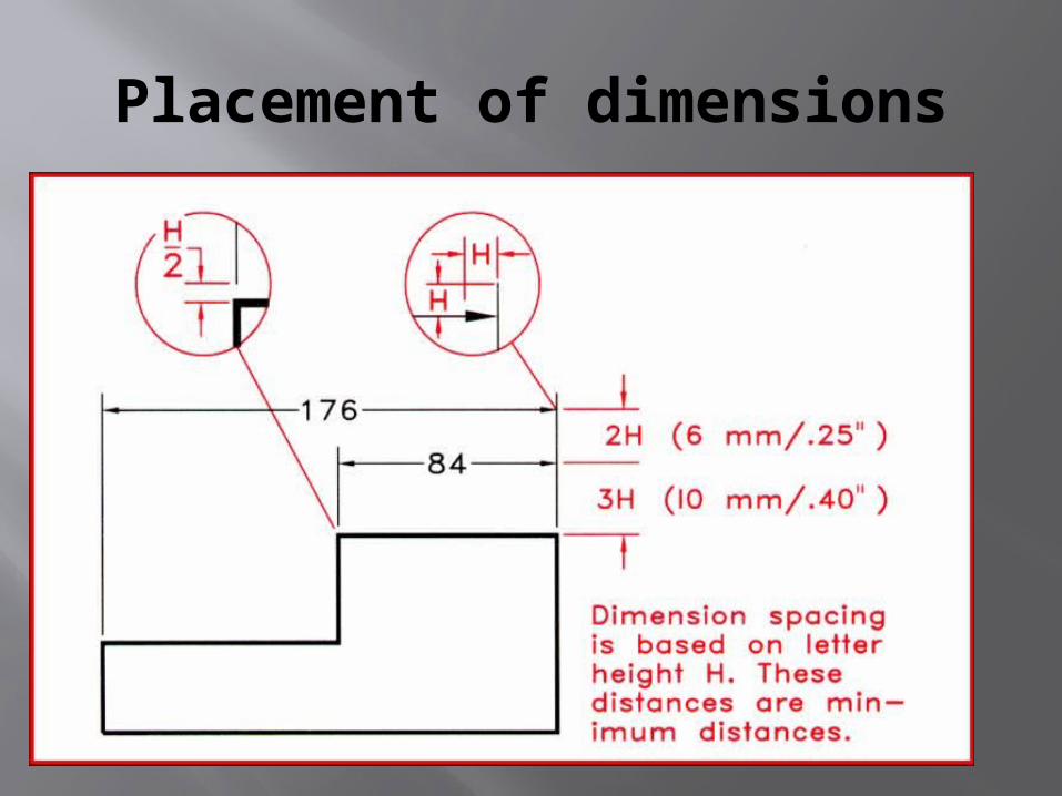
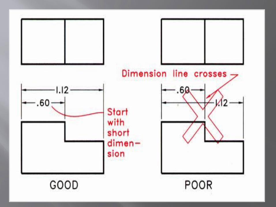
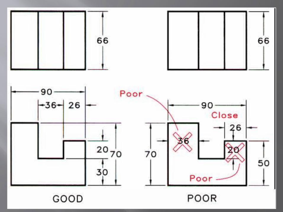
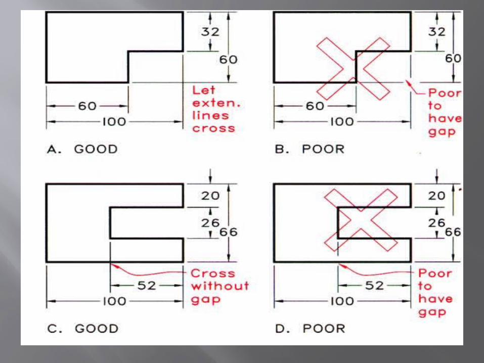
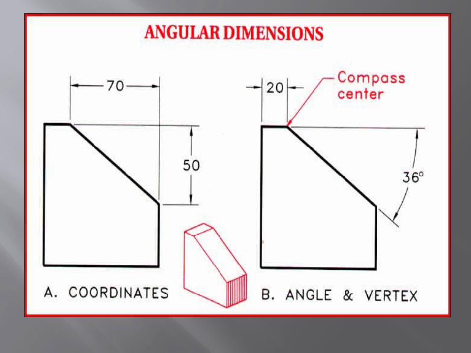
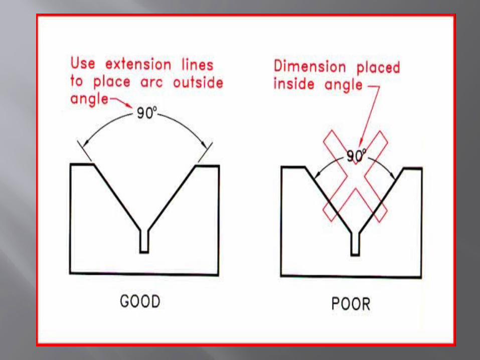
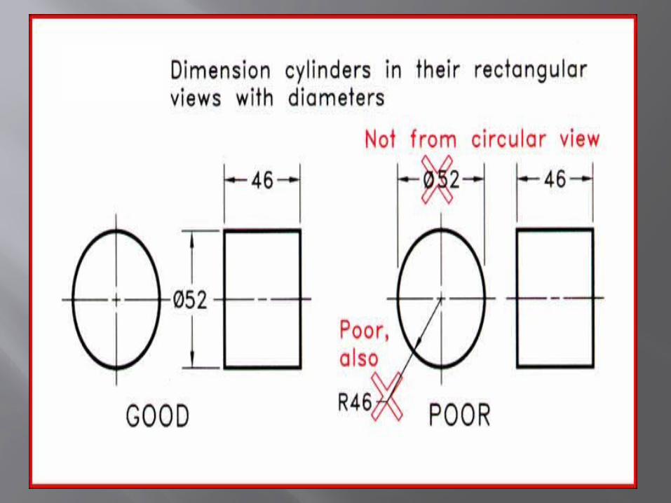
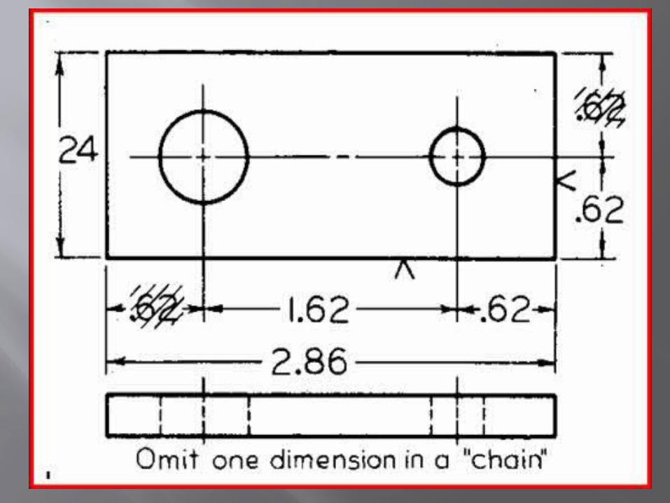
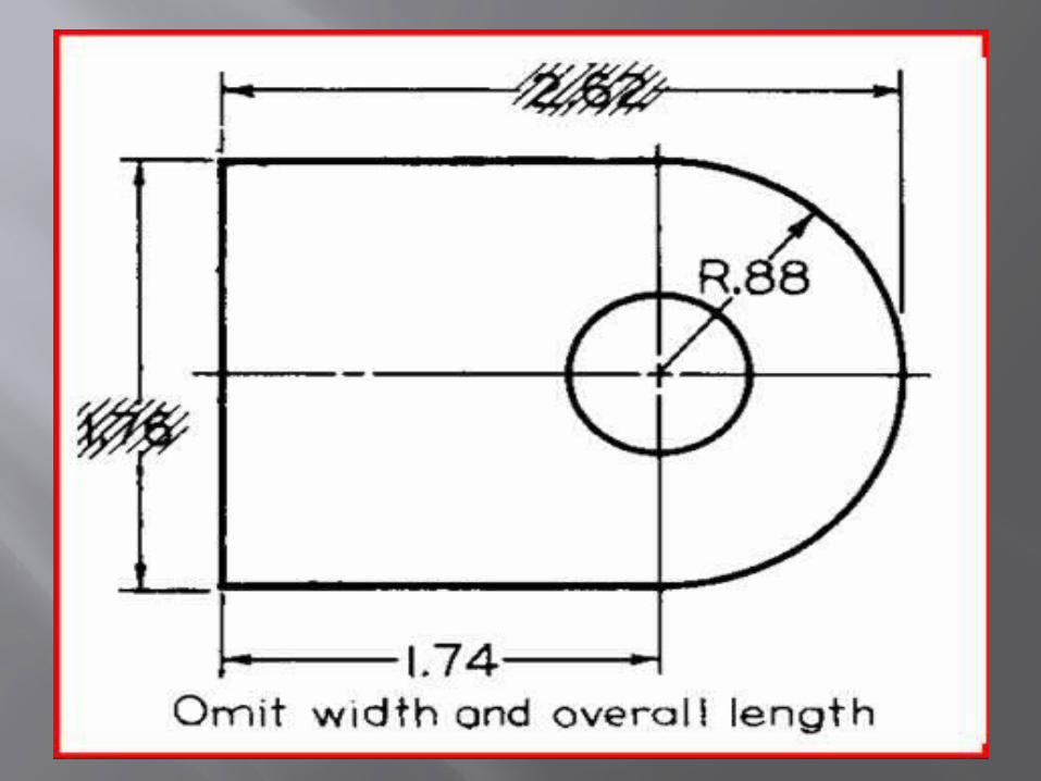
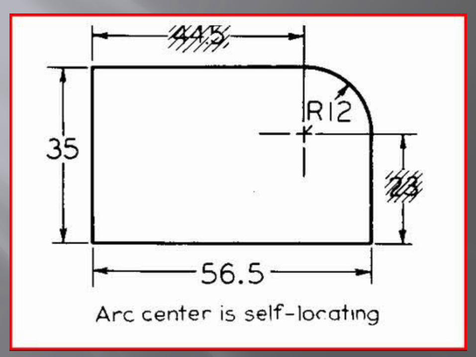
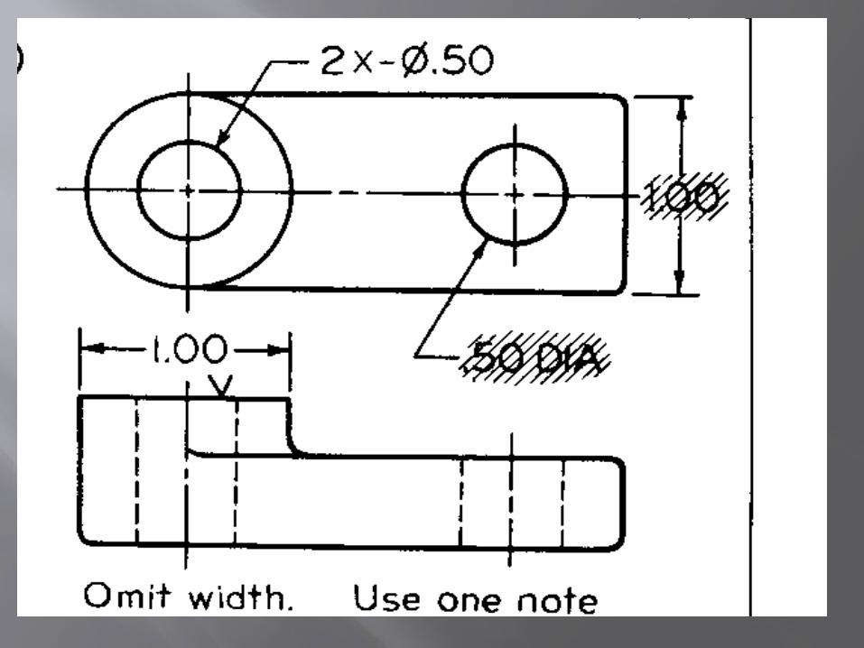
Placement of dimensions
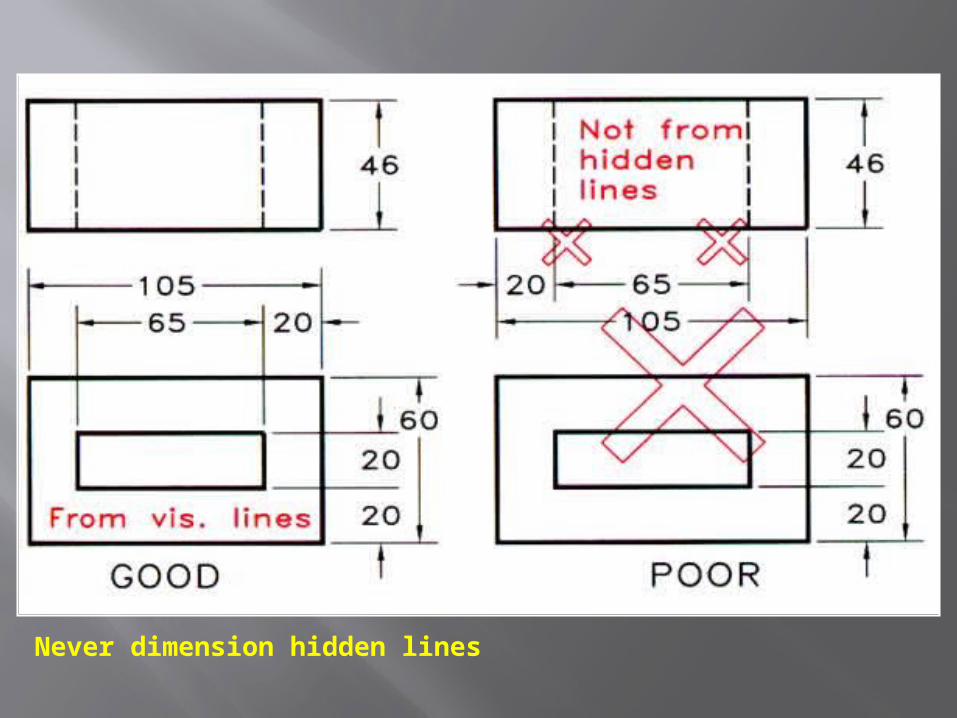
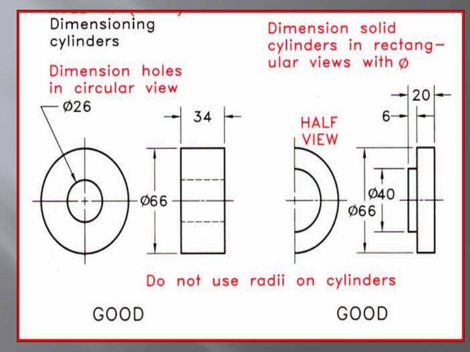
Never dimension hidden lines

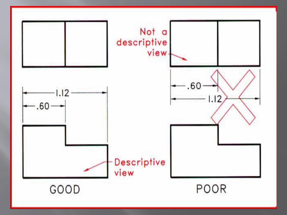
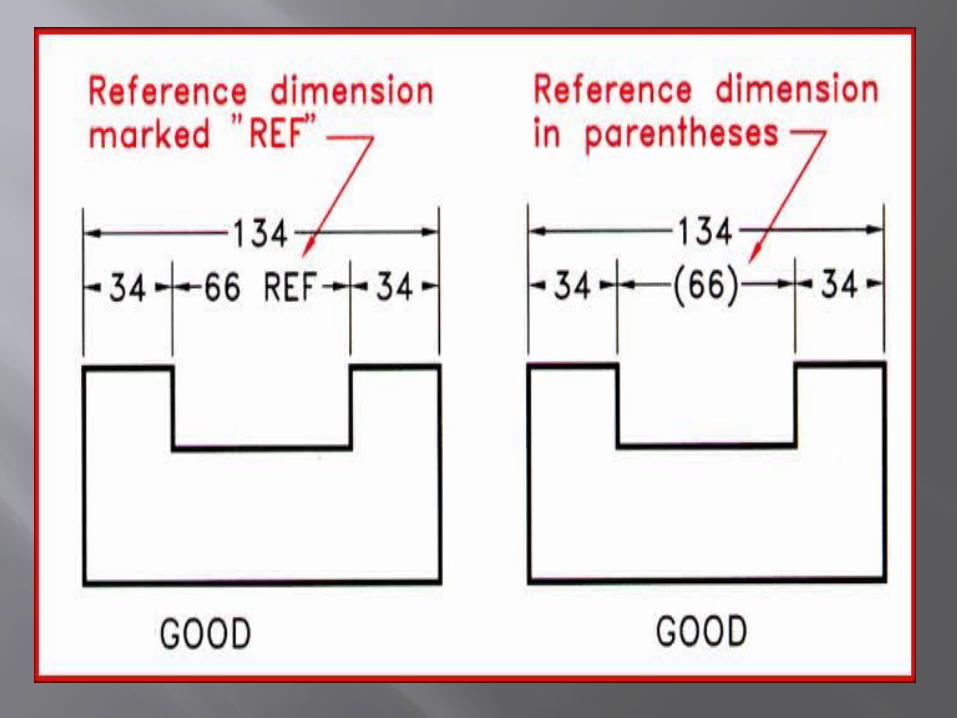
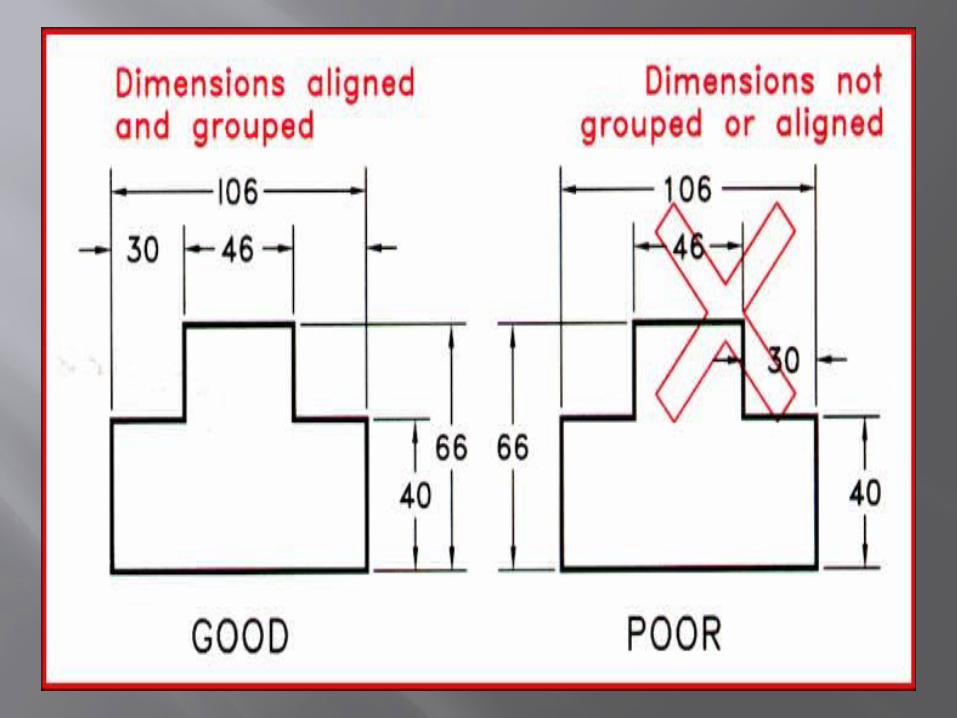
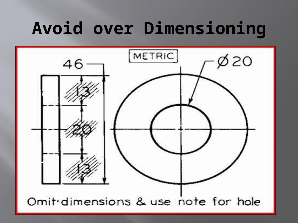
Avoid over Dimensioning
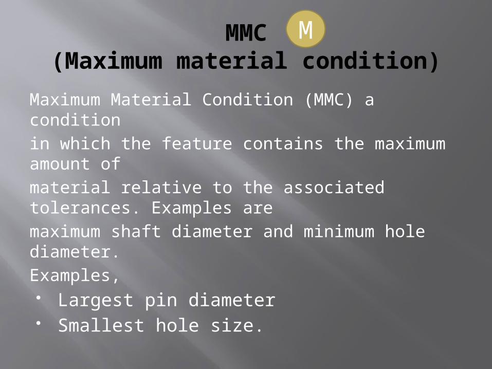
MMC(Maximum material condition)
Maximum Material Condition (MMC) a conditionin which the feature contains the maximum amount ofmaterial relative to the associated tolerances. Examples aremaximum shaft diameter and minimum hole diameter.Examples, Largest pin diameter Smallest hole size.
M
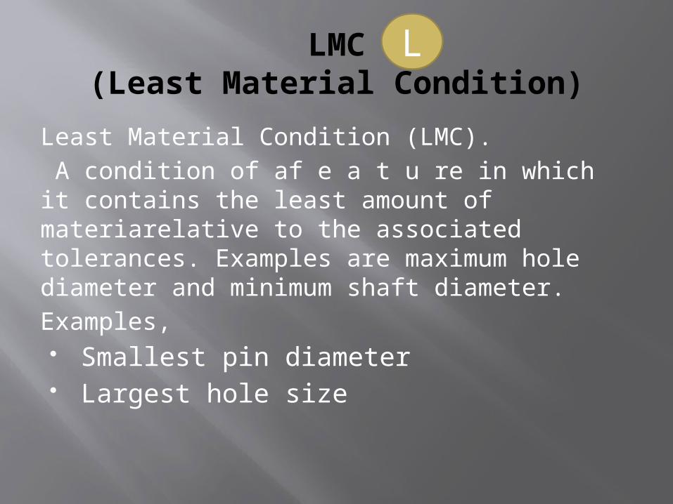
LMC(Least Material Condition)
Least Material Condition (LMC). A condition of af e a t u re in which it contains the least amount of materiarelative to the associated tolerances. Examples are maximum hole diameter and minimum shaft diameter.Examples, Smallest pin diameter Largest hole size
L
Allowance
Allowance is defined as an intentional difference between the maximum material limits of mating parts. Allowance is the minimum clearance (positive allowance), or maximum interference (negative allowance) between mating parts.Calculation formula isALLOWANCE = MMC HOLE – MMC SHAFT.
Clearance
Clearance is defined as the loosest fit or maximum intended difference between mating parts.
The calculation formula for clearance is:CLEARANCE = LMC HOLE – LMC SHAFT
FIT
Fit is generally term used to signify the range of tightness or looseness which may result from the application of a specific combination of allowance and tolerance in the design of mating part features.
Fits are of generally three types a.Clearance fit b.Interference fit c.Transition fit
Clearance Fit
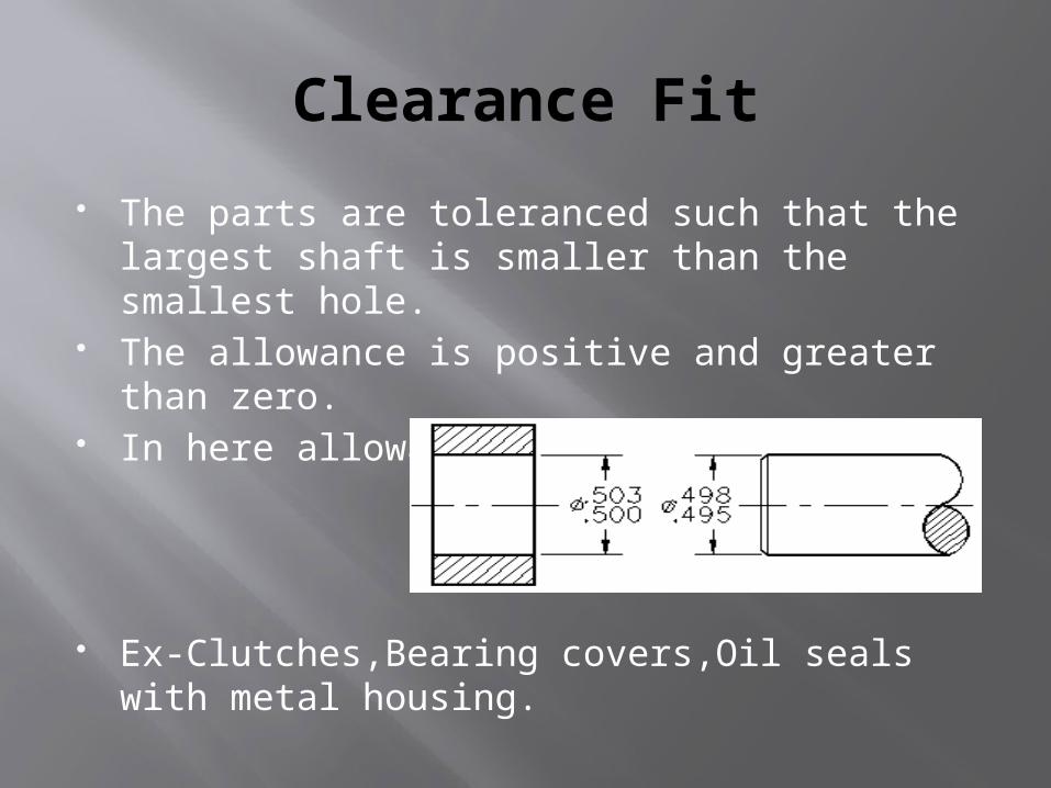
The parts are toleranced such that the largest shaft is smaller than the smallest hole.
The allowance is positive and greater than zero.
In here allowance>0
Ex-Clutches,Bearing covers,Oil seals with metal housing.

Interference Fit
Considerable pressure is required to assemble these fits and the parts are considered more or less permenently assembled.
In here allowance=0
Examples-gear wheels,couplings,valve seats.
Transition Fit
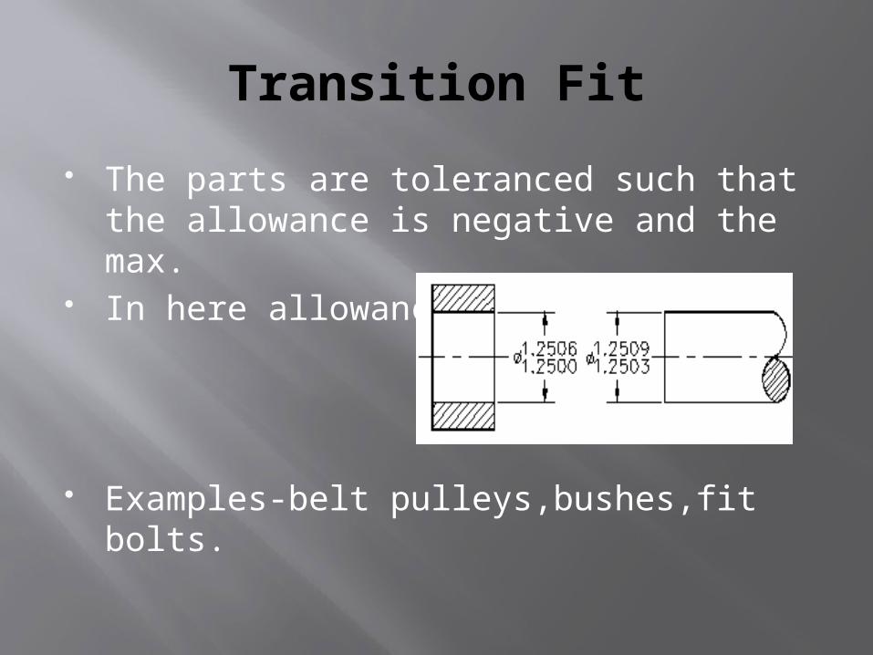
The parts are toleranced such that the allowance is negative and the max.
In here allowance<0
Examples-belt pulleys,bushes,fit bolts.
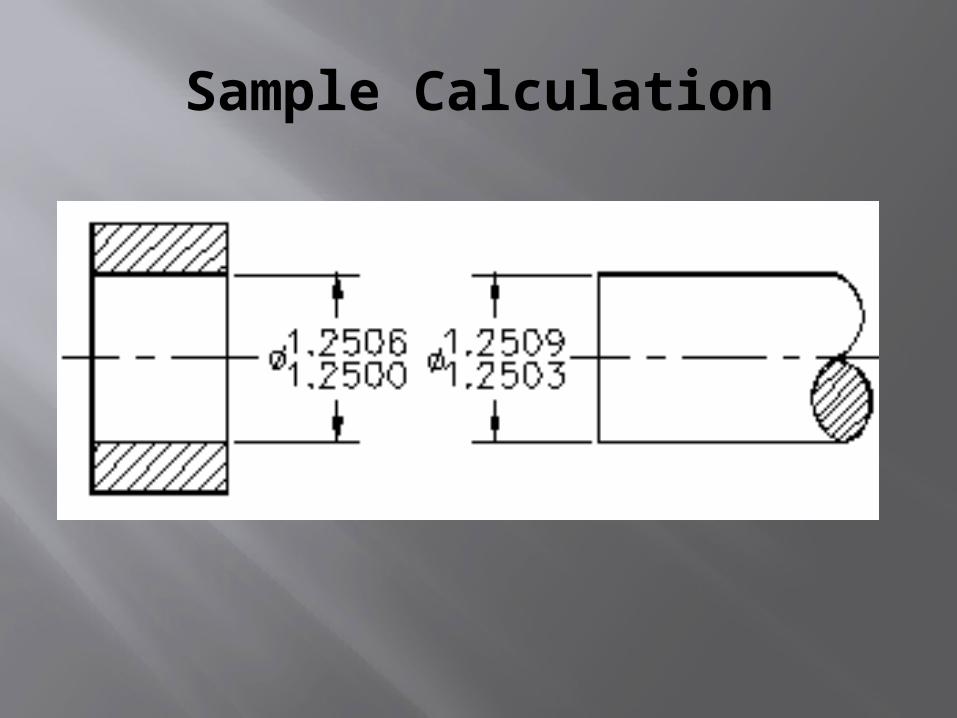
Sample Calculation
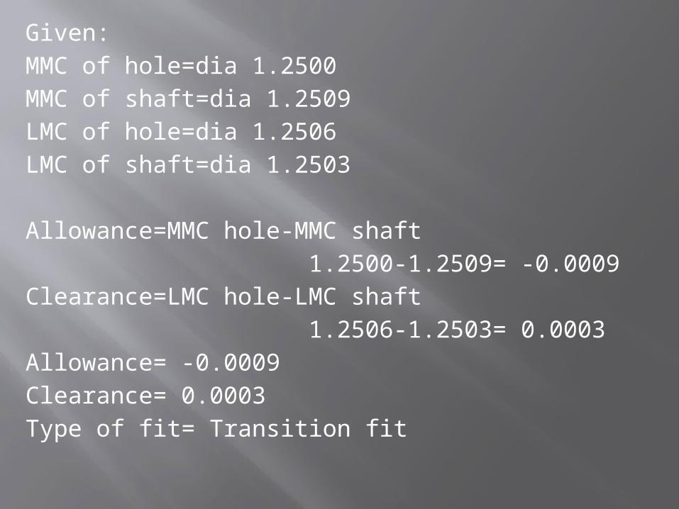
Given:MMC of hole=dia 1.2500MMC of shaft=dia 1.2509LMC of hole=dia 1.2506LMC of shaft=dia 1.2503
Allowance=MMC hole-MMC shaft 1.2500-1.2509= -0.0009Clearance=LMC hole-LMC shaft 1.2506-1.2503= 0.0003Allowance= -0.0009Clearance= 0.0003Type of fit= Transition fit
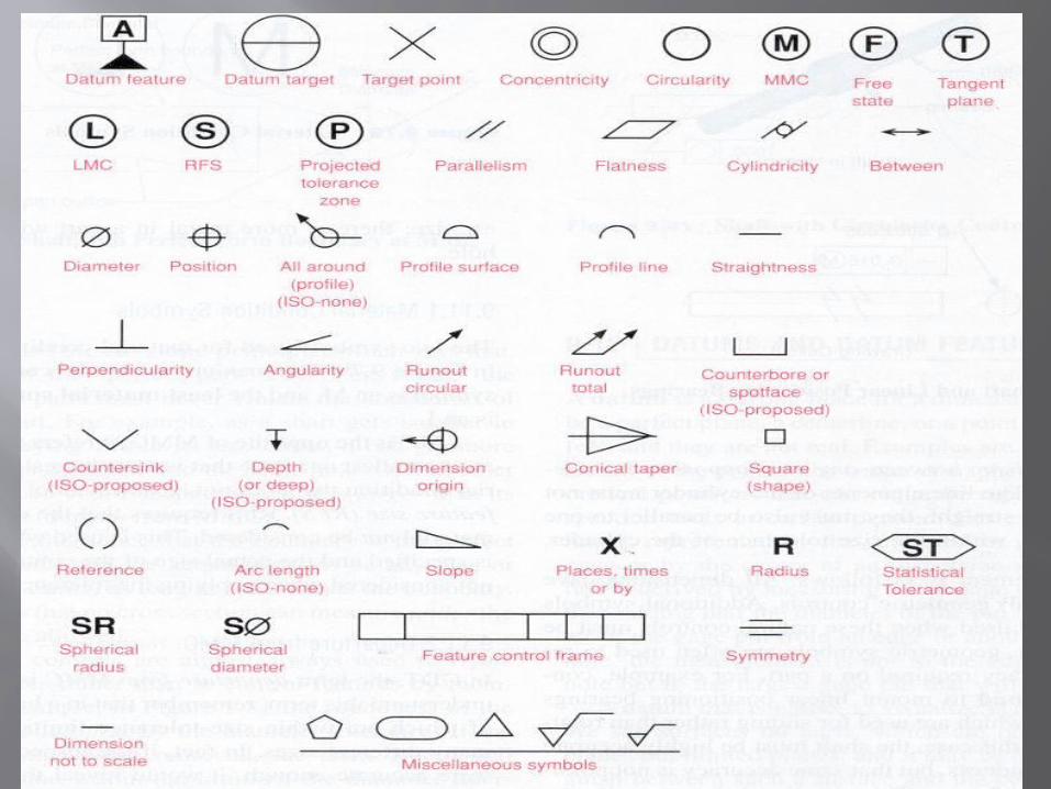
GD&T SYMBOLS
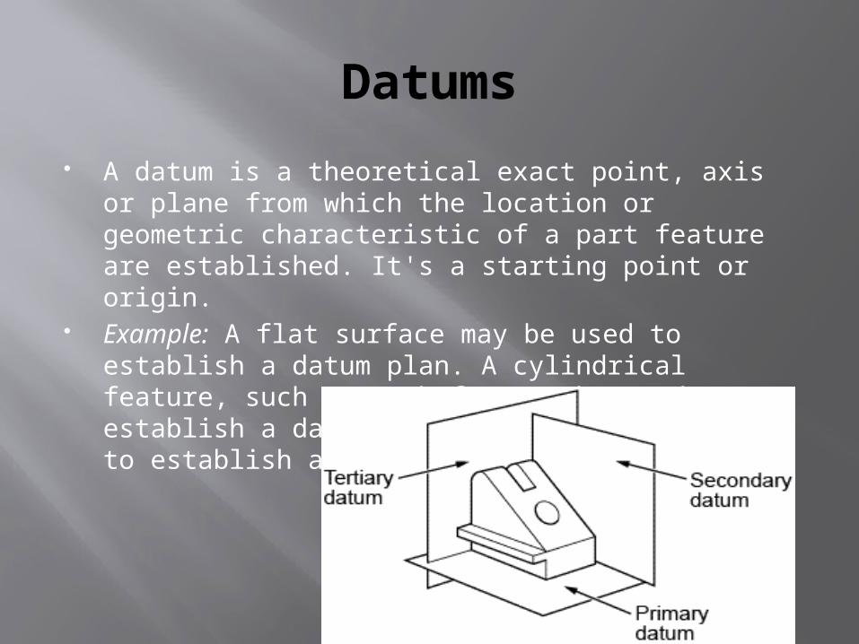
Datums
A datum is a theoretical exact point, axis or plane from which the location or geometric characteristic of a part feature are established. It's a starting point or origin.
Example: A flat surface may be used to establish a datum plan. A cylindrical feature, such as a shaft, may be used to establish a datum axis. A slot may be used to establish a datum center plane.
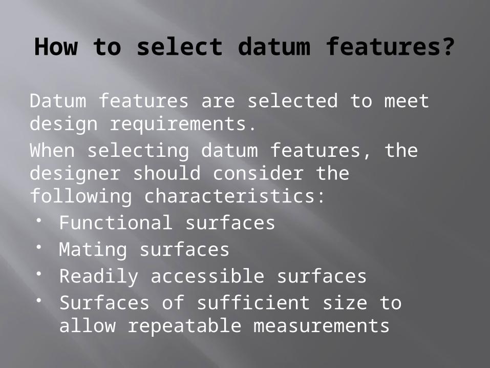
How to select datum features?
Datum features are selected to meet design requirements. When selecting datum features, the designer should consider the following characteristics: Functional surfaces Mating surfaces Readily accessible surfaces Surfaces of sufficient size to allow
repeatable measurements
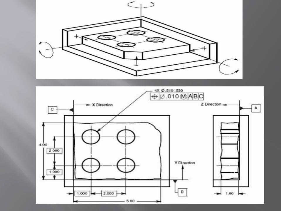
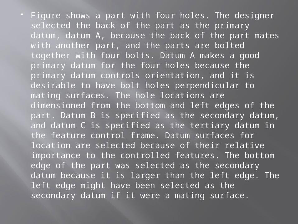
Figure shows a part with four holes. The designer
selected the back of the part as the primary datum, datum A, because the back of the part mates with another part, and the parts are bolted together with four bolts. Datum A makes a good primary datum for the four holes because the primary datum controls orientation, and it is desirable to have bolt holes perpendicular to mating surfaces. The hole locations are dimensioned from the bottom and left edges of the part. Datum B is specified as the secondary datum, and datum C is specified as the tertiary datum in the feature control frame. Datum surfaces for location are selected because of their relative importance to the controlled features. The bottom edge of the part was selected as the secondary datum because it is larger than the left edge. The left edge might have been selected as the secondary datum if it were a mating surface.
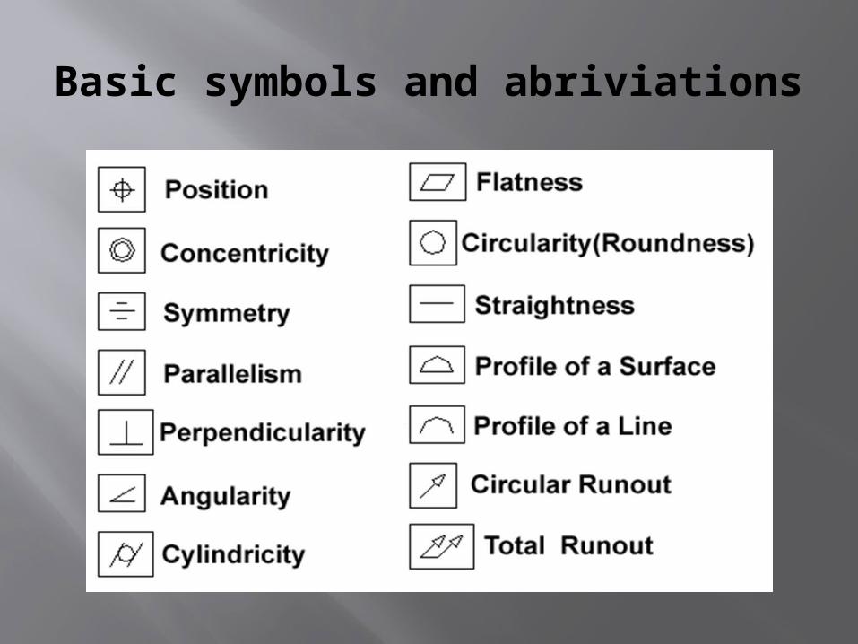
Basic symbols and abriviations
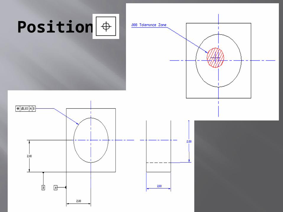
Position
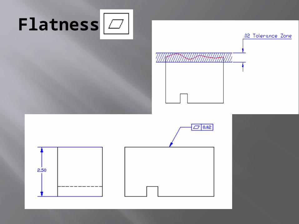
Flatness
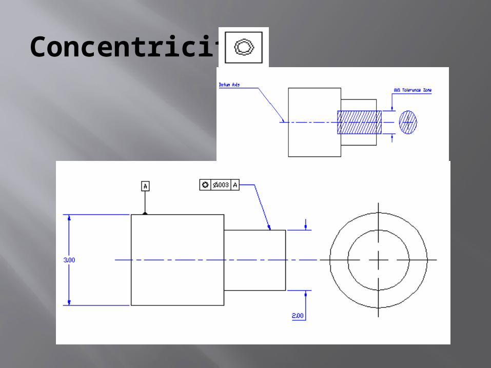
Concentricity
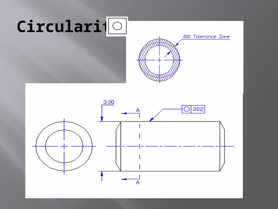
Circularity
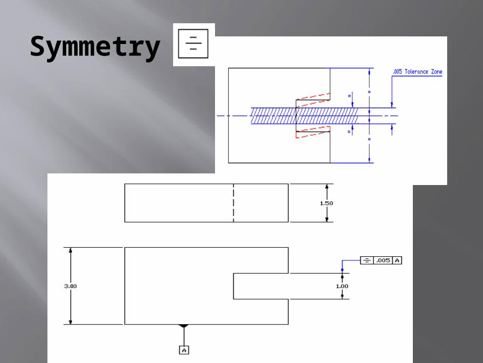
Symmetry
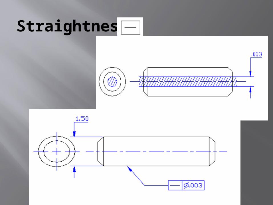
Straightness
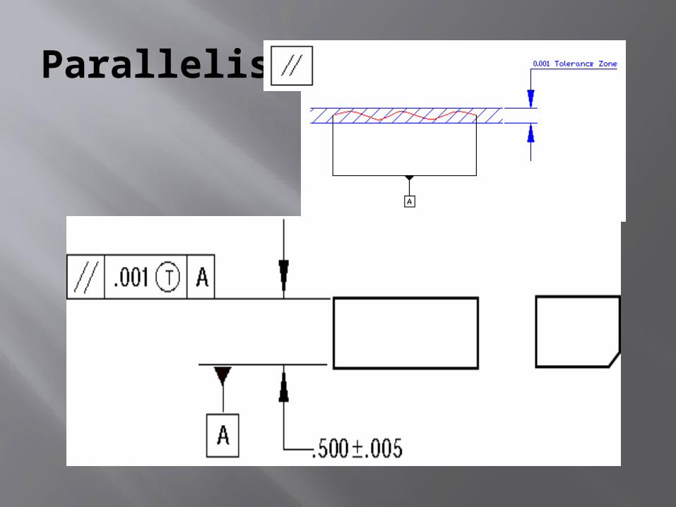
Parallelism
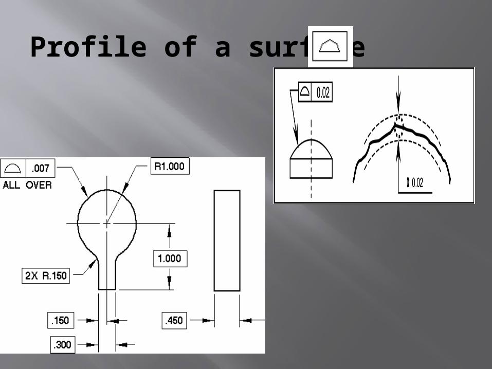
Profile of a surface
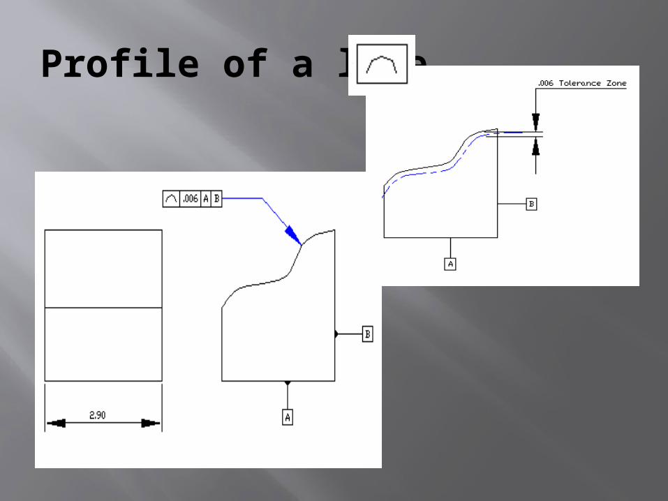
Profile of a line
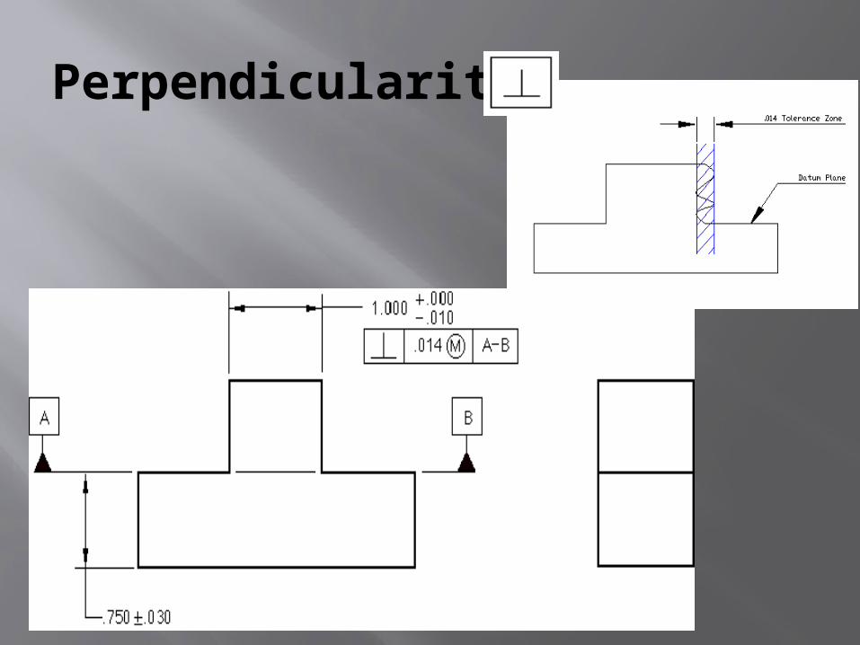
Perpendicularity
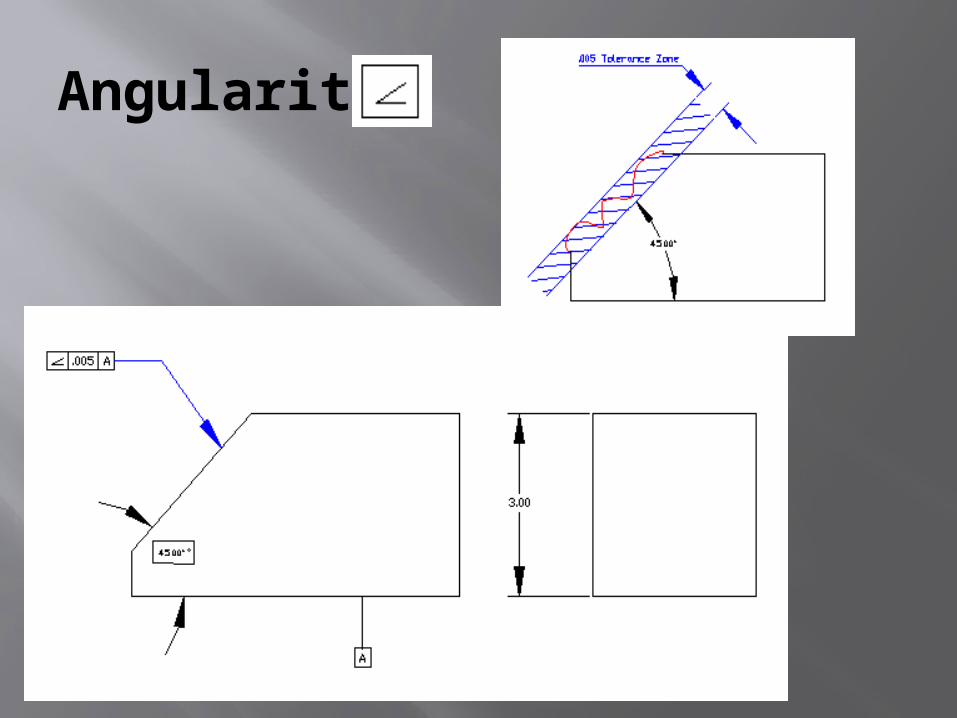
Angularity
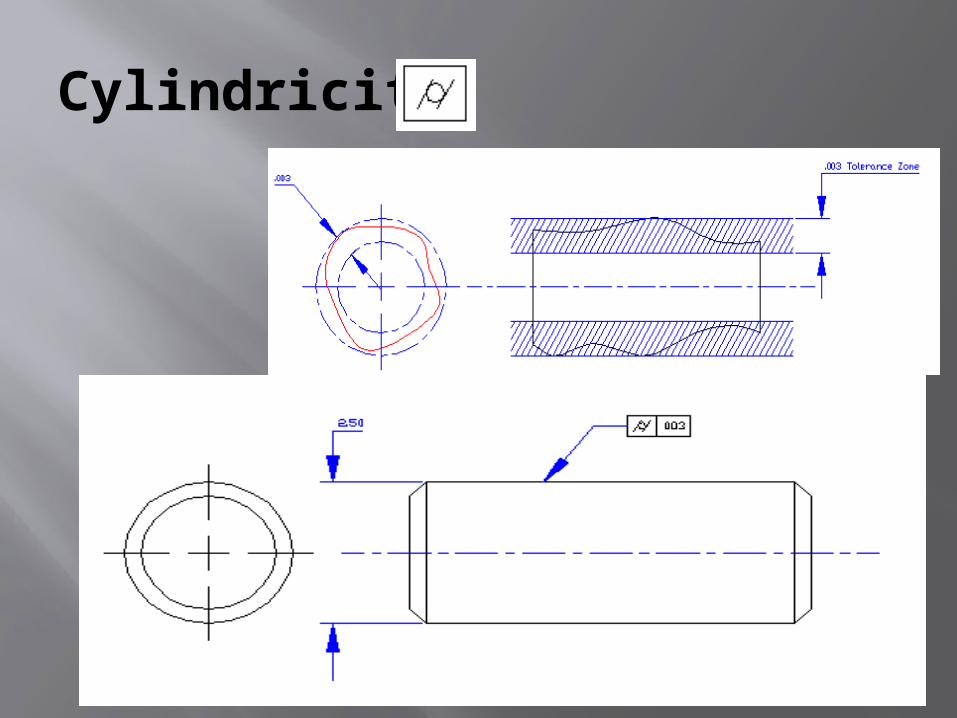
Cylindricity
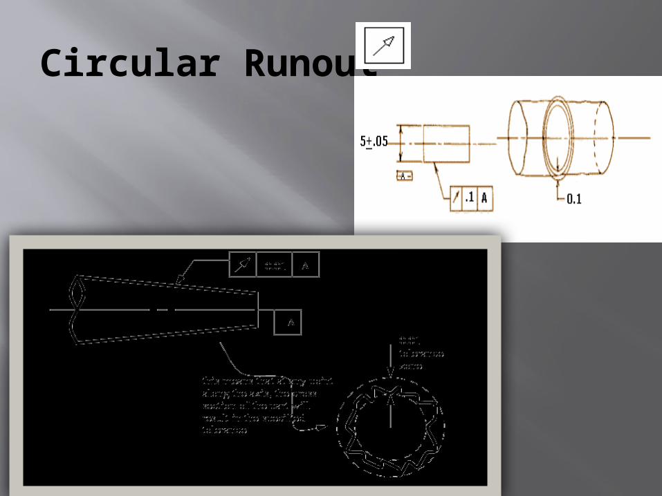
Circular Runout
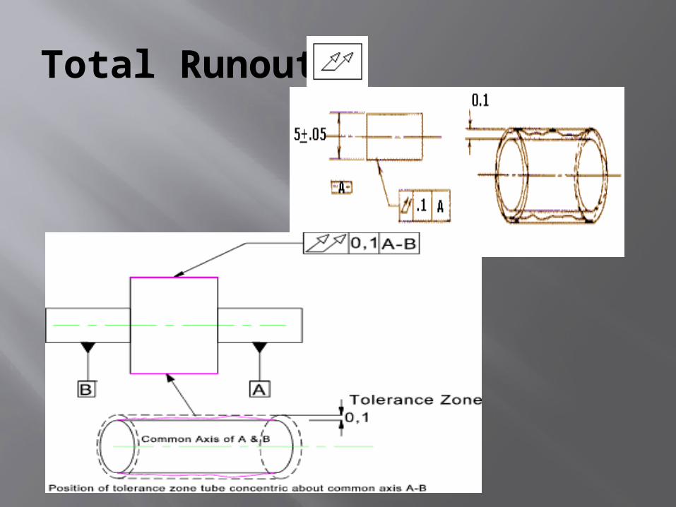
Total Runout

THANK YOU
Prepared by VASUDEVAN
Related Documents