9980 Indiana Avenue ● Suite 14 ● Riverside ● California ● 92503 ● Phone (951) 688-5400 ● Fax (951) 688-5200 5714 West 96 th Street ● Los Angeles ● California ● 90045 ● Phone (310) 337-9400 ● Fax (310) 337-0200 www.geomatlabs.com [email protected] GeoMat Testing Laboratories, Inc. Soil Engineering, Environmental Engineering, Materials Testing, Geology October 6, 2020 Project No.: 20229-01 TO: San Bernardino City Unified School District Facilities Planning and Development 956 West 9 th Street San Bernardino, California 92411 SUBJECT: Preliminary Soil Investigation Report for Access Ramp at Kimbark Elementary School, 18021 West Kenwood Avenue, San Bernardino, California In accordance with your authorization, GeoMat Testing Laboratories, Inc. (GeoMat) is pleased to present our Preliminary Soil Investigation Report for the proposed access ramp at 18021 West Kenwood Avenue, San Bernardino, California. This report is in fulfillment of our proposal dated September 29, 2020 and your subsequent authorization. The accompanying report presents a summary of our findings, recommendations and limitation of work for the proposed site development. The primary purpose of this investigation and report is to provide an evaluation of the existing geotechnical conditions at the site as they relate to the design and construction of the proposed development. More specifically, this investigation was to address geotechnical conditions for the preliminary design of the foundation for the proposed ramp structure. Based on the results of our investigation, the proposed development is feasible from a geotechnical standpoint and it is our professional opinion that the proposed development will not be subject to a hazard from settlement, slippage, or landslide, provided the recommendations of this report are incorporated into the proposed development. It is also our opinion that the proposed development will not adversely affect the geologic stability of the site or adjacent properties provided the recommendations contained in this report are incorporated into the proposed construction. We appreciate the opportunity to assist you and look forward to future projects. If you should have any questions regarding this report, please do not hesitate to call our office. We appreciate this opportunity to be of service. Submitted for GeoMat Testing Laboratories, Inc. Haytham Nabilsi, GE 2375 Art Martinez Project Engineer Staff Engineer [email protected] [email protected] Distribution: (3) Addressee

Welcome message from author
This document is posted to help you gain knowledge. Please leave a comment to let me know what you think about it! Share it to your friends and learn new things together.
Transcript

9980 Indiana Avenue ● Suite 14 ● Riverside ● California ● 92503 ● Phone (951) 688-5400 ● Fax (951) 688-5200 5714 West 96th Street ● Los Angeles ● California ● 90045 ● Phone (310) 337-9400 ● Fax (310) 337-0200
www.geomatlabs.com [email protected]
GeoMat Testing Laboratories, Inc. Soil Engineering, Environmental Engineering, Materials Testing, Geology
October 6, 2020 Project No.: 20229-01
TO: San Bernardino City Unified School District
Facilities Planning and Development 956 West 9th Street San Bernardino, California 92411
SUBJECT: Preliminary Soil Investigation Report for Access Ramp at Kimbark Elementary School, 18021
West Kenwood Avenue, San Bernardino, California In accordance with your authorization, GeoMat Testing Laboratories, Inc. (GeoMat) is pleased to present our Preliminary Soil Investigation Report for the proposed access ramp at 18021 West Kenwood Avenue, San Bernardino, California. This report is in fulfillment of our proposal dated September 29, 2020 and your subsequent authorization. The accompanying report presents a summary of our findings, recommendations and limitation of work for the proposed site development. The primary purpose of this investigation and report is to provide an evaluation of the existing geotechnical conditions at the site as they relate to the design and construction of the proposed development. More specifically, this investigation was to address geotechnical conditions for the preliminary design of the foundation for the proposed ramp structure. Based on the results of our investigation, the proposed development is feasible from a geotechnical standpoint and it is our professional opinion that the proposed development will not be subject to a hazard from settlement, slippage, or landslide, provided the recommendations of this report are incorporated into the proposed development. It is also our opinion that the proposed development will not adversely affect the geologic stability of the site or adjacent properties provided the recommendations contained in this report are incorporated into the proposed construction. We appreciate the opportunity to assist you and look forward to future projects. If you should have any questions regarding this report, please do not hesitate to call our office. We appreciate this opportunity to be of service. Submitted for GeoMat Testing Laboratories, Inc.
Haytham Nabilsi, GE 2375 Art Martinez Project Engineer Staff Engineer [email protected] [email protected] Distribution: (3) Addressee

Preliminary Soil Investigation Report – Proposed Access Ramp Project No. 20229-01 18021 West Kenwood Avenue, San Bernardino, California October 6, 2020
GeoMat Testing Laboratories, Inc. geomatlabs.com TOC: i
TABLE OF CONTENTS
1.0 INTRODUCTION ........................................................................................................................................... 1
1.1 EXISTING SITE CONDITIONS .......................................................................................................................... 1
1.2 PROPOSED DEVELOPMENT ........................................................................................................................... 1
1.3 FIELD WORK ...................................................................................................................................................... 1
1.4 LABORATORY TESTING ................................................................................................................................... 1
2.0 GEOTECHNICAL CONDITIONS ................................................................................................................. 2
2.1 REGIONAL GEOLOGIC FINDINGS .................................................................................................................. 2
2.2 SUBSURFACE CONDITIONS ........................................................................................................................... 2
2.3 GROUNDWATER ............................................................................................................................................... 2
2.4 EXPANSIVE SOIL............................................................................................................................................... 2
2.5 CORROSIVE SOIL ............................................................................................................................................. 3
2.6 SEISMIC DESIGN PARAMETERS .................................................................................................................... 3
2.7 SLOPE STABILITY ............................................................................................................................................. 4
3.0 TENTATIVE RECOMMENDATIONS ........................................................................................................... 5
3.1 EARTHWORK RECOMMENDATIONS ............................................................................................................. 5
3.2 TEMPORARY EXCAVATIONS .......................................................................................................................... 6
3.3 FOUNDATION RECOMMENDATIONS ............................................................................................................. 6
3.4 SLABS-ON-GRADE ............................................................................................................................................ 7
3.5 RETAINING WALLS ........................................................................................................................................... 8
3.6 SITE DRAINAGE ................................................................................................................................................ 8
4.0 ADDITIONAL SERVICES ............................................................................................................................. 9
5.0 GEOTECHNICAL RISK .............................................................................................................................. 10
6.0 LIMITATION OF INVESTIGATION ............................................................................................................ 10
ATTACHMENTS: Figure 1 Site Location Map Plate 1 Exploratory Boring Location Map Plate 2 Geotechnical Cross Section A-A’ Plate 3 Typical Retaining Wall Drainage Detail APPENDIX: Appendix A Selected References Appendix B Geotechnical Boring Logs Appendix C Laboratory Test Results Appendix D 2019 CBC Seismic Design Parameters Appendix E Slope Stability Analysis

Preliminary Soil Investigation Report – Proposed Access Ramp Project No. 20229-01 18021 West Kenwood Avenue, San Bernardino, California October 6, 2020
GeoMat Testing Laboratories, Inc. geomatlabs.com Page: 1
1.0 INTRODUCTION
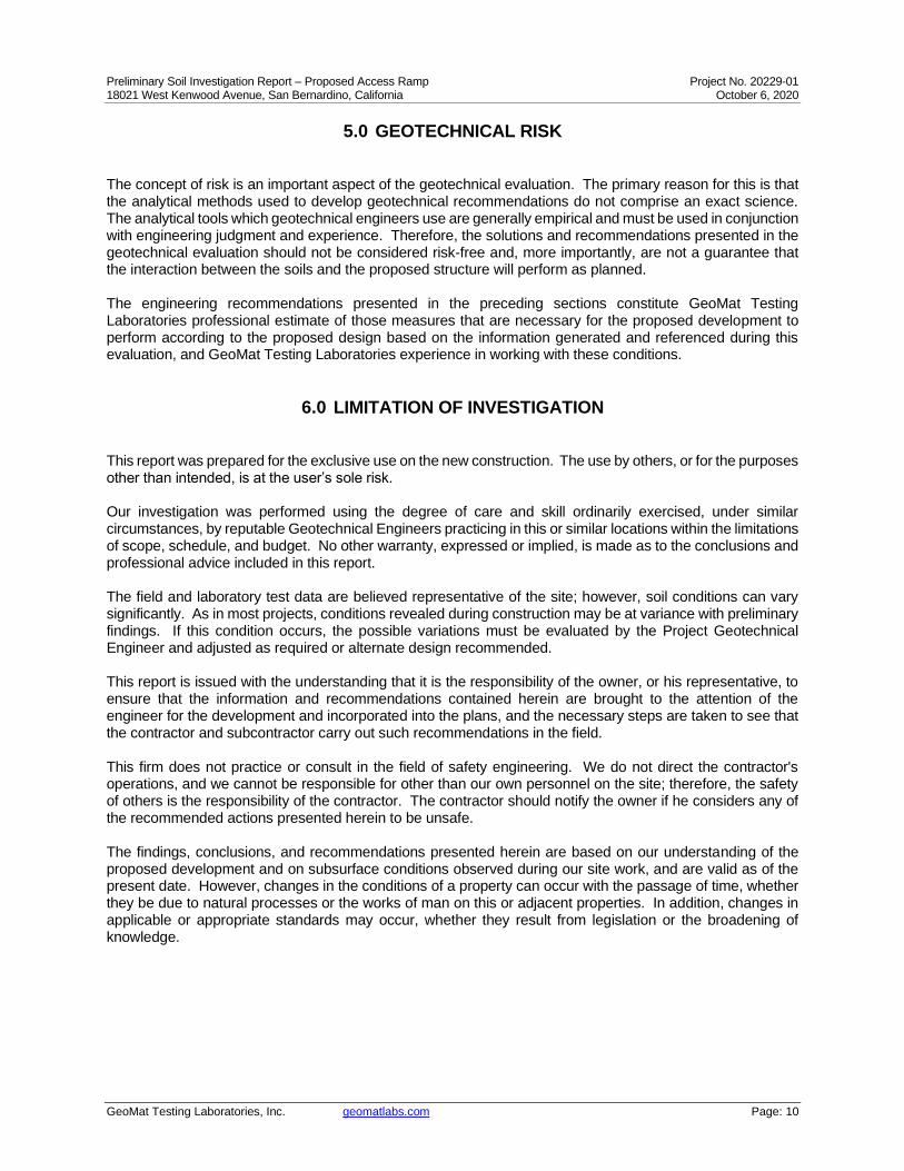
1.1 EXISTING SITE CONDITIONS The subject site is located on the south side of Kenwood Avenue between Kimbark Avenue and Woodlawn Avenue in San Bernardino, California. More specifically, the subject site is the sloped landscaping area located between the school building and the Kenwood Avenue street parking spaces. This sloped landscaped area generally consists of grass ground cover and several mature trees. The slope gradient is approximately 3H:1V for a total height of 12 feet. 1.2 PROPOSED DEVELOPMENT We understand that the site is proposed for an access ramp connecting the upper street level parking spaces to the lower school building level. The ramp will be of a switchback form and be constructed from concrete slab-on-grade and founded on continuous shallow footings. 1.3 FIELD WORK Three exploratory borings were excavated on October 4, 2020 to maximum depth of 4 feet below existing ground surface utilizing manual digging and auguring tools. Sampling was conducted with a Dames and Moore California Ring Sampler (see Exploratory Boring Location Map, Plate 1). This sampler has three inches external diameter, 2.5 inches inside diameter, and is lined with one-inch high brass rings, with an inside diameter of 2.41-inches. The sample barrel was driven into the ground at the bottom of the excavation with 35-pound hammer with a free fall of approximately 24-inches. Sampler driving resistance, expressed as number of blows for 12-inch of penetration, was recorded. To convert the field blow count to an SPT equivalent, we have utilized the following conversion formula by D.M. Burmister, 1948, “The importance and practical use of relative density in soil mechanics: Proceedings of ASTM, v. 48:1249” and the correlating SPT “N” values can be found in the borehole logs. 1.4 LABORATORY TESTING Laboratory tests were performed on selected soil samples. The tests consisted primarily of the following:
• Moisture Content (ASTM D2216)
• Dry Density (ASTM D2937)
• Sieve Analysis (ASTM D422)
• Direct Shear (ASTM D3080)
• Soluble Sulfate Content (Extinction/Turbidimetric Method)
The soil classifications are in conformance with the Unified Soil Classifications System (USCS), as outlined in the Classification and Symbols Chart (Appendix B). A summary of our laboratory testing, ASTM designation, and graphical presentation of test results is presented in Appendix C.
Preliminary Soil Investigation Report – Proposed Access Ramp Project No. 20229-01 18021 West Kenwood Avenue, San Bernardino, California October 6, 2020
GeoMat Testing Laboratories, Inc. geomatlabs.com Page: 2
2.0 GEOTECHNICAL CONDITIONS
2.1 REGIONAL GEOLOGIC FINDINGS Based on the Geologic Map of the Devore quadrangle (Dibblee Foundation Map DF-105) the site is located in an area mapped as older alluvial fan deposits (Qoa). These deposits are generally described as consisting of low elevated remnants of alluvial gravel and sand. 2.2 SUBSURFACE CONDITIONS Detailed log of the exploratory excavation is presented in Appendix B of this report. The earth materials encountered within the exploratory excavations are generally described below. Based on our exploratory boreholes, the site soil generally consists of silty sand with gravel (USCS “SM”) to the total depth explored of 4 feet below existing ground surface. This material is generally described as loose in the upper 18 inches and become medium dense, dry to slightly moist, and contains few to some gravel. 2.3 GROUNDWATER Groundwater study is not within the scope of our work. Groundwater was not encountered in our exploratory borings excavated onsite to a depth of 4’ below ground surface. A contour map showing minimum depths to ground water in the Santa Ana River Valley Region was constructed by the United States Geological Survey (USGS) and subsequently, a report (USGS Map MF-1802) was published in 1985. The map was constructed by contouring the shallowest water level measurements reported to the California Department of Water Resources (CDWR) for the period from 1973-1979. Based on our review of the map, the minimum depth to ground water in the project site area, during this period, may be around 10 feet below ground surface. Please note that the potential for rain or irrigation water locally seeping through from elevated areas and showing up near grades cannot be precluded. Our experience indicates that surface or near-surface groundwater conditions can develop in areas where groundwater conditions did not exist prior to site development, especially in areas where a substantial increase in surface water infiltration results from landscape irrigation. Fluctuations in perched water elevations are likely to occur in the future due to variations in precipitation, temperature, consumptive uses, and other factors including mounding of perched water over bedrock or natural soil. Mitigation for nuisance shallow seeps moving from elevated lower areas will be needed if encountered. These mitigations may include subdrains, horizontal drains, toe drains, french drains, heel drains or other devices. 2.4 EXPANSIVE SOIL Expansive soils are characterized by their ability to undergo significant volume changes (shrink or swell) due to variations in moisture content. Changes in soil moisture content can result from precipitation, landscape irrigation, utility leakage, roof drainage, perched groundwater, drought, or other factors and may result in unacceptable settlement or heave of structures or concrete slabs supported on grade. Based on laboratory classification, the upper foundation soil onsite is expected to have a very low expansion potential (EI<20), as defined in ASTM D4829. This would require verification subsequent to completion of new footing excavations.

Preliminary Soil Investigation Report – Proposed Access Ramp Project No. 20229-01 18021 West Kenwood Avenue, San Bernardino, California October 6, 2020
GeoMat Testing Laboratories, Inc. geomatlabs.com Page: 3
2.5 CORROSIVE SOIL To preliminarily assess the sulfate exposure of concrete in contact with the site soils, a representative soil sample was tested for water-soluble sulfate content. The test results suggest the site soils have a negligible potential for sulfate attack (less than 0.015 percent) based on commonly accepted criteria. We recommend following the procedures provided in ACI 318-19, Section 19.3, Table 19.3.2.1 for exposure “S0”. We recommend Type II cement for all concrete work in contact with soil. Ferrous metal pipes should be protected from potential corrosion by bituminous coating, etc. We recommend that all utility pipes be nonmetallic and/or corrosion resistant. Recommendations should be verified by soluble sulfate and corrosion testing of soil samples obtained from specific locations at the completion of rough grading.
2.6 SEISMIC DESIGN PARAMETERS Based on current standards, the proposed development is expected to be designed in accordance with the requirements of the 2019 California Building Code (CBC). The 2019 California Building Code (CBC) provides procedures for earthquake resistant structural design that include considerations for on-site soil conditions, occupancy, and the configuration of the structure including the structural system and height. Based on the soils encountered in the exploratory borehole within the subject site and with consideration of the geologic units mapped in the area, it is our opinion that the site soil profile corresponds to Site Class D in accordance with Section 1613.2.2 of the California Building Code (CBC 2019) and Chapter 20 of ASCE/SEI 7-16. We have downloaded the seismic design parameters in accordance with the provisions of the current California Building Code (CBC, 2019) and ASCE/SEI 7-16 Standard using the Structural Engineers Association of California, OSHPD Seismic Design Maps Web Application (https://seismicmaps.org). The mapped seismic parameters are attached to this report in Appendix D. The 2019 CBC requires that a site-specific ground motion study be performed in accordance with Section 11.4.8 of ASCE 7-16 for Site Class D sites with a mapped S1 value greater than 0.2. However, Section 11.4.8 of ASCE 7-16 also indicates an exception (exception 2) to the requirement for a site specific ground motion hazard analysis for certain structures on Site Class D sites. Also, the commentary for Section 11 of ASCE 7-16 (Page 534 of Section C11 of ASCE 7-16) indicates that “In general, this exception effectively limits the requirements for site-specific hazard analysis to very tall and or flexible structures at Site Class D sites.” Based on our understanding of the proposed development, the seismic design parameters presented below were calculated assuming that the exception in Section 11.4.8 applies to the proposed structure at this site. However, the structural engineer should verify that this exception is applicable to the proposed structure. Based on the exception, the spectral response accelerations presented below were calculated using the site coefficients Fa and Fv from ASCE 7-16 Tables 11.4-1 and 11.4-2.
2019 CBC SEISMIC DESIGN PARAMETERS Short Period Site Coefficient Fa 1.200 Long Period Site Coefficient Fv 1.700 Mapped Spectral Acceleration at 0.2 sec Period Ss 2.454 Mapped Spectral Acceleration at 1.0 sec Period S1 1.045 Site Class D Site Modified Spectral Acceleration at 0.2 sec Period SMS 2.945 Site Modified Spectral Acceleration at 1.0 sec Period SM1 1.777 Design Spectral Acceleration at 0.2 sec Period SDS 1.964 Design Spectral Acceleration at 1.0 sec Period SD1 1.184
The above tabulated values as well as the values obtained from the website seismicmaps.org (US seismic design maps) are sufficient assuming a site specific ground motion hazard analysis is not required per exception 2 of ASCE 7-16 Section 11.4.8 and Section 11 commentary of ASCE 7-16.

Preliminary Soil Investigation Report – Proposed Access Ramp Project No. 20229-01 18021 West Kenwood Avenue, San Bernardino, California October 6, 2020
GeoMat Testing Laboratories, Inc. geomatlabs.com Page: 4
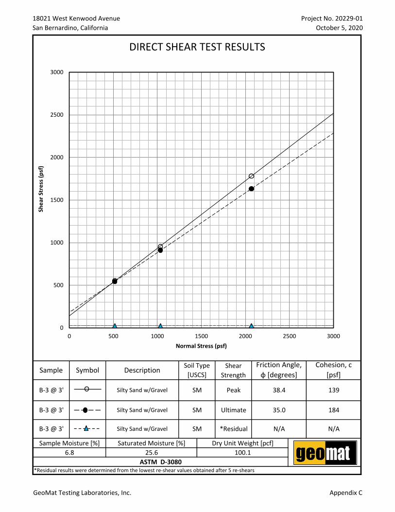
2.7 SLOPE STABILITY The stability of the proposed slope and ramp configuration at the subject site was evaluated by analyzing the elevations obtained from Civil Grading Plan prepared by Sitetech, Inc (Sheet C-3, 06/24/2020) as depicted in our Geotechnical Cross Section A-A’ on Plate 2. 2.7.1 Soil Strength Parameters The shear strength parameters used in the stability analyses were based on laboratory test results of relatively undisturbed soil samples obtained from the onsite material. The following table summarizes the parameters used in the stability analysis. Analysis Type Material Strength Parameter Friction Angle (°) Cohesion (psf) Unit Weight (pcf)
Surficial/Global Alluvium Ultimate Strength ɸ = 34.1 C = 184 γ = 120
2.7.2 Surficial Stability Surficial stability of the slope was analyzed for the onsite slope assuming an infinite 2H:1V slope with seepage parallel to the slope surface and consistent subsoil profile. The failure plane for this case is parallel to the surface of slope and the limit equilibrium method can be applied readily. The following factor of safety is derived from a homogeneous c-ɸ soil based on effective stress analysis. The results of the analyses indicate that the existing slopes have a minimum factor of safety of 1.78 for surficial stability under static condition.
Factor of Safety = 𝐶+𝐻∗𝛾𝑏∗𝑐𝑜𝑠2(𝛽) tan(𝜑)
𝛾𝑠𝑎𝑡∗𝐻∗sin(𝛽)cos (𝛽)
Where: H = 3 feet (saturation zone) γb = 58 pcf (buoyant soil unit weight) γsat = 130 pcf (saturated soil unit weight) β = 26.6 ° (slope angle)
Considering the shear strength of soil and the slope inclination, seasonal local surficial sloughing cannot be entirely precluded and should be considered by the project design team. Permanent devices should be designed by the project civil engineer such as but not limited to wall free board, “V” ditches, benches, etc., to minimize and contain any remote pop-outs. In addition, to minimize the potential for surficial sloughing the slope should be maintained with appropriate deep root vegetation and ground cover. 2.7.3 Global Stability Analysis Global stability analysis was performed to evaluate the probable static and dynamic gross stability of the existing slope configuration. The analyses utilize the simplified method of slices by Bishop through the software program GEOSTASE and the upper boundary theorem of plasticity through the software program LimitState:GEO. The results of the slope stability analyses are provided in Appendix E of this report. The seismic stability of the site was calculated in conformance with the Southern California Earthquake Center (SCEC), 2002, "Recommended Procedures for Implementation of DMG Special Publication 117, Guidelines for Analyzing and Mitigating Landslide Hazards in California,” and the California Geological Survey (CGS), Special Publication 117A, 2008 "Guidelines for Evaluating and Mitigating Seismic Hazards in California." A seismic coefficient (Keq) of 0.473 was utilized in our analysis and was derived based on a maximum allowable displacement of 5 cm, a computed PGAM of 1.266g, a moment magnitude of 7.9, and a distance to the ground motion source of 1.3 km. Our analyses indicate that the existing slopes have a minimum factor of safety of 3.08 and 1.28 under static and pseudo-static conditions, respectively. Based on our field observation and slope stability analyses, the existing slopes are considered stable. Continuing stability of the slope will greatly depend on controlling the water, proper planting and maintaining the drainage for proper functioning. Drainage control measures recommended in this report and the project civil engineer should be implemented during site development.

Preliminary Soil Investigation Report – Proposed Access Ramp Project No. 20229-01 18021 West Kenwood Avenue, San Bernardino, California October 6, 2020
GeoMat Testing Laboratories, Inc. geomatlabs.com Page: 5
3.0 TENTATIVE RECOMMENDATIONS
3.1 EARTHWORK RECOMMENDATIONS The following recommendations are provided regarding aspects of the anticipated earthwork construction. These recommendations should be considered subject to revision based on additional geotechnical evaluation of the conditions observed by the Geotechnical Engineer during site development. 3.1.1 Site Clearing, Grubbing and Fill Removal All debris, undocumented fill, abandoned utility lines, roots, irrigation appurtenances, underground structures, deleterious materials, etc., should be removed and hauled offsite. Cavities created during site clearance should be backfilled in a controlled manner. 3.1.2 Slab-on-Grade Preparation The slab subgrade should be scarified to a depth of at least 8-inches below proposed subgrade soil elevation, moisture conditioned, and recompacted to at least 90 percent relative compaction. 3.1.3 Footing Preparation The footing excavations should be observed by the soil engineer. The footings should be excavated into competent native soil that is determined to be firm and unyielding. If loose soil is encountered in the bottom of the footing excavations, we recommend deepening the footing excavation into competent native material. The bottom of the excavation should be void from slough. 3.1.4 Trench Backfill All utility trenches and retaining wall backfills should be mechanically compacted to the minimum requirements of at least 90 percent relative compaction. Onsite soils derived from trench excavations can be used as trench backfill except for deleterious materials. Soils with sand equivalent greater than 30 may be utilized for pipe bedding and shading. Pipe bedding should be required to provide uniform support for piping. Excavated material from footing trenches should not be placed in slab-on-grade areas unless properly compacted and tested. 3.1.5 Compacted Fills/Imported Soils Any soil to be placed as fill, whether presently onsite or import, should be approved by the soil engineer or his representative prior to their placement. All onsite soils to be used as fill should be cleansed of any roots, or other deleterious materials. Rocks larger than 8-inches in diameter should be removed from soil to be used as compacted fill. All fills should be placed in 6- to 8-inch loose lifts, thoroughly watered, or aerated to near optimum moisture content, mixed and compacted to at least 90 or 95 percent relative compaction depending on the material (subgrade soil or aggregate base) and application (pavement subgrade, building pad, etc.). This is relative to the maximum dry density determined by ASTM D1557 Test Method. Any imported soils should be sandy (preferably USCS "SM" or "SW", and very low in expansion potential) and approved by the soil engineer. The soil engineer or his representative should observe the placement of all fill and take sufficient tests to verify the moisture content and the uniformity and degree of compaction obtained.

Preliminary Soil Investigation Report – Proposed Access Ramp Project No. 20229-01 18021 West Kenwood Avenue, San Bernardino, California October 6, 2020
GeoMat Testing Laboratories, Inc. geomatlabs.com Page: 6
3.2 TEMPORARY EXCAVATIONS All excavation slopes and shoring systems should meet the minimum requirements of the Occupational Safety and Health (OSHA) Standards. Maintaining safe and stable slopes on excavations is the responsibility of the contractor and will depend on the nature of the soils and groundwater conditions encountered and his method of excavation. Excavations during construction should be carried out in such a manner that failure or ground movement will not occur. The contractor should perform any additional studies deemed necessary to supplement the information contained in this report for the purpose of planning and executing his excavation plan. 3.2.1 Cal/OSHA Soil Type The subsurface soil expected to be encountered during site development may be classified as “Soil Type B” per the California Occupational Safety and Health Administration (Cal/OSHA). 3.2.2 Excavation Characteristics The upper soil onsite is generally composed of medium dense silty sand with gravel which is not expected to exhibit difficult excavation resistance for typical excavating equipment in good working condition. 3.2.3 Safe Vertical Cuts Temporary un-surcharged excavations of 4 feet high may be made at a vertical gradient for short periods of time. Temporary un-surcharged excavations greater than 4 feet may be trimmed back at 1H:1V gradients to a maximum height of 10 feet. Exposed conditions during construction should be verified by the project geotechnical engineer. No excavations should take place without the direct supervision of the project geotechnical engineer. If potentially unstable soil conditions are encountered, modifications of slope ratios for temporary cuts may be required. 3.2.4 Excavation Setbacks No excavations should be conducted, without special considerations, along property lines, public right-of-ways, or existing foundations, where the excavation depth will encroach within the “zone of influence”. The “zone of influence” of the existing footings, property lines, or public right-of-way may be assumed to be below a 45-degree line projected down from the bottom edge of the footing, property line, or right-of-way. 3.3 FOUNDATION RECOMMENDATIONS The proposed ramp may be supported on conventional shallow foundation systems deriving support in competent native soil (see Section 3.1.3 Footing Preparation). Foundations should be deepened as necessary to penetrate through soft or disturbed soil at the discretion of the Geotechnical Engineer. All foundation excavations must be observed and approved by the Geotechnical Engineer’s representative, prior to placing steel reinforcement or concrete. 3.3.1 Bearing Capacity Spread, continuous, or pad-type foundations carried at least 36-inches below the lowest adjacent grade may be designed to impose a net dead-plus-live load pressure of 2000 psf. The bearing capacity may be increased 15 percent for every additional foot of embedment, to a maximum allowable bearing pressure of 2500 psf. A one-third increase may be used for wind or seismic loads.

Preliminary Soil Investigation Report – Proposed Access Ramp Project No. 20229-01 18021 West Kenwood Avenue, San Bernardino, California October 6, 2020
GeoMat Testing Laboratories, Inc. geomatlabs.com Page: 7
3.3.2 Lateral Resistance Resistance to lateral footing will be provided by passive earth pressure and base friction. For footings bearing against firm native material, passive earth pressure may be considered to be developed at a rate of 280 psf per foot of depth to a maximum of 2000 psf. Base friction may be computed at 0.40 times the normal load. If passive earth pressure and friction are combined to provide required resistance to lateral forces, the value of the passive pressure should be reduced to two-thirds the value. 3.3.3 Settlement The onsite soils below the foundation depth have relatively high strengths and will not be subject to significant stress increases from foundations of the new structure. Therefore, estimated total long-term static and seismic settlement between similarly loaded adjacent foundation systems should not exceed 1-inch. The structures should be designed to tolerate a differential settlement on the order of 1/2-inch over a 30-foot span. 3.3.4 Reinforcement Footing reinforcement should be determined by the structural engineer; however, minimum reinforcement should be at least two No. 4 reinforcing bars, top and bottom. Reinforcement and size recommendations presented in this report are considered the minimum necessary for the soil conditions present at the foundation level and are not intended to supersede the design of the project structural engineer or criteria of the governing agencies for the project. 3.4 SLABS-ON-GRADE Slabs-on-grade should be at least 4-inches thick and reinforced with at least No. 4 bars at 16-inches on-center both ways, properly centered in mid thickness of slabs. The structural engineer should design the actual slab thickness and reinforcement based on structural load requirements. 3.4.1 Modulus of Subgrade Reaction A coefficient of vertical subgrade reaction (KV) of 130 psi/in may be assumed for the building pad compacted fill soils. The modulus of subgrade reaction was estimated based on the NAVFAC 7.1 design charts. This value is for a small loaded area (1 sq. ft or less) such as for wheel loads or point loads and should be adjusted for larger loaded areas, as necessary. 3.4.2 Capillary Break & Vapor Membrane If vinyl or other moisture-sensitive floor coverings are planned, we recommend that the floor slab in those areas be underlain by a vapor membrane and capillary break consisting of a minimum 10-mil vapor-retarding membrane over a 4-inch thick layer of clean sand. The 4-inch thick layer of sand should be placed between the subgrade soil and the membrane to decrease the possibility of damage to the membrane. 3.4.3 Slab Curling Precautions A low-slump concrete should be used to minimize possible curling of the slab. Additionally, a layer of sand may be placed over the vapor retarding membrane to reduce slab curling. If this sand bedding is used, care should be taken during the placement of the concrete to prevent displacement of the sand. However, the need for sand and/or the thickness of sand above the moisture vapor barrier should be specified by the structural engineer or concrete contractor. The selection of sand above the barrier is not a geotechnical engineering issue and hence outside our purview.

Preliminary Soil Investigation Report – Proposed Access Ramp Project No. 20229-01 18021 West Kenwood Avenue, San Bernardino, California October 6, 2020
GeoMat Testing Laboratories, Inc. geomatlabs.com Page: 8
3.4.4 Subgrade Exposure Construction activities and exposure to the environment can cause deterioration of the prepared subgrade. Therefore, we recommend that our field representative observe the condition of the final subgrade soils immediately prior to slab-on-grade construction, and, if necessary, perform further density and moisture content tests to determine the suitability of the final prepared subgrade. Additionally, the slab subgrade should be moisture conditioned to 2 to 4 percent above the optimum moisture content, to a depth of 12 inches. The moisture content of the floor slab subgrade soils should be verified by the geotechnical engineer within 24 hours prior to placing the vapor retarding membrane. 3.5 RETAINING WALLS The following lateral earth pressures, in conjunction with the lateral resistance parameters provided in the Foundation Recommendations section of this report, may be used for the design of retaining walls with free draining compacted backfills. If passive earth pressure and friction are combined to provide required resistance to lateral forces, the value of the passive pressure should be reduced to two-thirds the following recommendations.
Lateral Earth Pressure Condition
Soil Backfill Condition
Equivalent Fluid Pressure (pcf)
Earth Pressure Coefficient
Active Case (Drained)* Level 34 Ka = 0.28
At-Rest Case (Drained) Level 53 Ko = 0.44
Total Unit Weight of Soil 120 pcf
All retaining walls and block walls footings should be founded in compacted fill or firm native soils. We recommend drainage for retaining walls to be provided in accordance with Plate 3 of this report. Maximum precautions should be taken when placing drainage materials and during backfilling. All wall backfills should be properly compacted to at least 90 percent relative compaction. 3.6 SITE DRAINAGE Positive drainage should be provided and maintained for the life of the project around the perimeter of all structures (including slopes and retaining walls) and all foundations toward streets or approved drainage devices to minimize water infiltrating into the underlying natural and engineered fill soils. In addition, finish subgrade adjacent to exterior footings should be sloped down (at least 2%) and away to facilitate surface drainage. Perimeter water collection devices may be installed around the structure to collect roof/irrigation/natural drainage. Roof drainage should be collected and directed away from foundations via nonerosive devices. Over the slope drainage must not be permitted. Water, either natural or by irrigation, should not be permitted to pond or saturate the foundation soils. Planter areas and large trees adjacent to the foundations are not recommended. All planters and terraces should be provided with drainage devices. Internal drainage should be directed to approved drainage collection devices. Location of drainage device should be in accordance with the design civil engineer’s drainage and erosion control recommendations. The owner should be made aware of the potential problems, which may develop when drainage is altered through construction of retaining walls, patios and other devices. Ponded water, leaking irrigation systems, over watering or other conditions which could lead to ground saturation should be avoided. Surface and subsurface runoff from adjacent properties should be controlled. Area drainage collection should be directed through approved drainage devices. All drainage devices should be properly maintained.

Preliminary Soil Investigation Report – Proposed Access Ramp Project No. 20229-01 18021 West Kenwood Avenue, San Bernardino, California October 6, 2020
GeoMat Testing Laboratories, Inc. geomatlabs.com Page: 9
4.0 ADDITIONAL SERVICES
Plan Reviews The recommendations provided in this report are based on preliminary information and subsurface conditions as interpreted from limited exploratory boreholes at the site. We should be retained to review the final grading and foundation plans to revise our conclusions and recommendations, as necessary. Professional fees will apply for each review. Our conclusions and recommendations should also be reviewed and verified during site grading and revised accordingly if exposed geotechnical conditions vary from our preliminary findings and interpretations. Additional Observation and/or Testing GeoMat Testing Laboratories, Inc. should observe and/or test at the following stages of construction. • During slab-on-grade scarification and compaction. • Following footing excavation and prior to placement of footing materials. • During wetting of slab subgrade and prior to placement of slab materials. • During all trench backfill. • When any unusual conditions are encountered. Final Report of Compaction During Grading A final report of compaction control should be prepared subsequent to the completion of grading. The report should include a summary of work performed, laboratory test results, and the results and locations of field density tests performed during grading.
Preliminary Soil Investigation Report – Proposed Access Ramp Project No. 20229-01 18021 West Kenwood Avenue, San Bernardino, California October 6, 2020
GeoMat Testing Laboratories, Inc. geomatlabs.com Page: 10
5.0 GEOTECHNICAL RISK
The concept of risk is an important aspect of the geotechnical evaluation. The primary reason for this is that the analytical methods used to develop geotechnical recommendations do not comprise an exact science. The analytical tools which geotechnical engineers use are generally empirical and must be used in conjunction with engineering judgment and experience. Therefore, the solutions and recommendations presented in the geotechnical evaluation should not be considered risk-free and, more importantly, are not a guarantee that the interaction between the soils and the proposed structure will perform as planned. The engineering recommendations presented in the preceding sections constitute GeoMat Testing Laboratories professional estimate of those measures that are necessary for the proposed development to perform according to the proposed design based on the information generated and referenced during this evaluation, and GeoMat Testing Laboratories experience in working with these conditions.
6.0 LIMITATION OF INVESTIGATION
This report was prepared for the exclusive use on the new construction. The use by others, or for the purposes other than intended, is at the user’s sole risk. Our investigation was performed using the degree of care and skill ordinarily exercised, under similar circumstances, by reputable Geotechnical Engineers practicing in this or similar locations within the limitations of scope, schedule, and budget. No other warranty, expressed or implied, is made as to the conclusions and professional advice included in this report. The field and laboratory test data are believed representative of the site; however, soil conditions can vary significantly. As in most projects, conditions revealed during construction may be at variance with preliminary findings. If this condition occurs, the possible variations must be evaluated by the Project Geotechnical Engineer and adjusted as required or alternate design recommended. This report is issued with the understanding that it is the responsibility of the owner, or his representative, to ensure that the information and recommendations contained herein are brought to the attention of the engineer for the development and incorporated into the plans, and the necessary steps are taken to see that the contractor and subcontractor carry out such recommendations in the field. This firm does not practice or consult in the field of safety engineering. We do not direct the contractor's operations, and we cannot be responsible for other than our own personnel on the site; therefore, the safety of others is the responsibility of the contractor. The contractor should notify the owner if he considers any of the recommended actions presented herein to be unsafe. The findings, conclusions, and recommendations presented herein are based on our understanding of the proposed development and on subsurface conditions observed during our site work, and are valid as of the present date. However, changes in the conditions of a property can occur with the passage of time, whether they be due to natural processes or the works of man on this or adjacent properties. In addition, changes in applicable or appropriate standards may occur, whether they result from legislation or the broadening of knowledge.

SITE
Figure 1
DWN BY:
CHK'D BY:
DATUM:
PROJECTION:
SCALE:
REV. NO.:
PROJECT:
TITLE:
SITE LOCATION MAP
DATE:
PROJECT NO.:
FIGURE NO.:
AM
MN
--
--
1" = 1/2 MILE
--
OCTOBER 2020
20229-01
PRELIMINARY SOIL INVESTIGATION REPORT18021 KENWOOD AVENUE
SAN BERNARDINO, CALIFORNIA
USGS, THE NATIONAL MAP, US TOPO, DEVORE, 2018
0 0.25 0.5 1.0
APPROXIMATE SCALE (MILES)
geo matGeoMat Testing Laboratories, Inc.
9980 Indiana Avenue, Suite 14,Riverside, California

B-02
B-01
B-03
A'
A
LEGEND:
ALL LOCATIONS ARE APPROXIMATE
EXPLORATORY BORINGB-03
A A'
CROSS SECTION
EXPLORATORY BOREHOLE LOCATION MAP
18021 KENWOOD AVENUE
SAN BERNARDINO, CALIFORNIA
PLATE
1
DRAWN BY: AMgeo matGeoMat Testing Laboratories, Inc.
9980 Indiana Avenue, Suite 14,
Riverside, California
CHECKED BY: HMN
PROJECT NO.: 20229-01
SCALE: 1" = 20'
DATE: OCTOBER 2020
(11"x17")
PREPARED BY:

ELE
VA
TIO
N (ft)
A
2480'
2490'
2470'
2460'
B-01
TD=4'
B-02
TD=4'B-03
TD=4'
2480'
2490'
2470'
2460'
EXISTING GRADE
PROPOSED GRADE
A'
SILTY SAND WITH GRAVELSM
SM
SM
SM
GEOTECHNICAL CROSS SECTION A-A'
18021 KENWOOD AVENUE
SAN BERNARDINO, CALIFORNIA
PLATE
2
DRAWN BY: AMgeo matGeoMat Testing Laboratories, Inc.
9980 Indiana Avenue, Suite 14,
Riverside, California
CHECKED BY: HMN
PROJECT NO.: 20229-01
SCALE: 1" = 5'
DATE: OCTOBER 2020
(11"x17")
PREPARED BY:

OPTION 1: PIPE SURROUNDED WITH CLASS 2 PERMEABLE MATERIAL
WITH PROPERSURFACE DRAINAGE
12"
WATERPROOFING(SEE GENERAL NOTES)
CLASS 2 PERMEABLE FILTERMATERIAL (SEE GRADATION)
4 INCH DIAMETERPERFORATED PIPE
(SEE NOTE 3)
NATIVE
WEEP HOLE(SEE NOTE 5)
LEVEL ORSLOPE
SLOPE ORLEVEL
12"
WATERPROOFING(SEE GENERAL NOTES)
1/4 TO 1 1/2 INCH SIZEGRAVEL WRAPPED IN FILTER
FABRIC
NATIVE
WEEP HOLE(SEE NOTE 5)
LEVEL ORSLOPE
WITH PROPERSURFACE DRAINAGE
FILTER FABRIC(SEE NOTE 4)
SLOPE ORLEVEL
OPTION 2: GRAVEL WRAPPEDIN FILTER FABRIC
SUBDRAIN OPTIONS AND BACKFILL WHEN NATIVE MATERIAL HAS EXPANSION INDEX ≤ 50
Class 2 Filter Permeable Material GradationPer Caltrans Specifications
Sieve Size Percent Passing
1"3/4"3/8"
No. 4No. 8
No. 30No. 50
No. 200
10090-10040-10025-4018-335-150-70-3
GENERAL NOTES:
*Waterproofing should be provided where moisture nuisance problem through the wall is undesireable. *Water proofing of the walls is not under the purview of the geotechnical engineer.*All drains should have a gradient of 1 percent minimum.*Outlet portion of the subdrain should have a 4-inch diamater solid pipe discharged into a suitable disposal area designed by the project engineer. The subdrain pipe should be accessible for maintenance (rodding).*Other subdrain backfill options are subject to the review by the geotechnical engineer and modification of design parameters.
Notes:1) Sand should have a sand equivalent of 30 or greater and may be densified by water jetting.2) 1 Cu. ft. per ft. of 1/4 - to 1 1/2 -inch size gravel wrapped in filter fabric3) Pipe type should be ASTM D1527 Acrylonitrile Butadiene Styrene (ABS) SDR35 or ASTM D1785 Polyvinyl Chlorise plastic (PVC), Schedule 40, Armco A2000
PVC, or approved equivalent. Pipe should be installed with perforations down. Perforations should be 3/8 -inch in diameter placed at the ends of a 120-degree arc in two rows at 3-inch on center (staggered).
4) Filter Fabric should be Mirafi 140NC or approved equivalent.5) Weephole should be 3-inch minimum diameter and provided at 10-foot maximum intervals. if exposure is permitted, weepholes should be located 12-inches
above finished grade. If exposure is not permitted, such as for a wall adjacent to a sidewalk/curb, a pipe under the sidewalk to be discharged through the curb face or equivalent should be provided. For a basement-type wall, a proper subdrain outlet system should be provided.
6) Retaining wall plans should be reviewed and approved by the geotechnical engineer.7) Walls over six feet in height are subject to a special review by the geotechnical engineer and modifications to the above requirements.
12" MINIMUM
12" MINIMUM
RETAINING WALL BACKFILL AND SUBDRAIN DETAILPLATE
3

APPENDIX A

Preliminary Soil Investigation Report – Proposed Access Ramp Project No. 20229-01 18021 West Kenwood Avenue, San Bernardino, California October 6, 2020
GeoMat Testing Laboratories, Inc. geomatlabs.com Appendix A
SELECTED REFERENCES
Sitetech Inc. “Kimbark Elementary School, 1802 W. Kenwood Ave, San Bernardino, CA 92410,” Civil Grading Plan, Sheet C-3, June 24, 2020. City of San Bernardino General Plan, November 1, 2005 San Bernardino County Land Use Plan, Geologic Hazard Overlays, Sheet FH21C Dibblee, T.W., and Minch, J.A., 2003, Geologic map of the Devore quadrangle, San Bernardino County, California: Dibblee Geological Foundation, Dibblee Foundation Map DF-105, scale 1:24,000 USGS, Contour Map Showing Minimum Depth to Ground Water, Upper Santa Ana River Valley, California, 1973-1979, Scott E. Carson and Jonathan C. Matti, 1985. Department of Water Resources, Water Data Library USGS, National Water Information System, Web Interface, Groundwater Levels for California. USGS TopoView Interactive Webpage (https://ngmdb.usgs.gov/topoview/viewer/#4/39.98/-107.53) Structural Engineers Association of California, OSHPD Seismic Design Maps Interactive Website (https://seismicmaps.org/) California Geological Survey, Map No. 6, Fault Activity Map of California, Compiled by Charles W. Jennings and William A. Bryant, California Geologic Data Map Series, 2010 Department of the Navy, Design Manual 7.01, Soil Mechanics, September 1986. Department of the Navy, Design Manual 7.02, Foundation and Earth Structures, September 1986. Department of the Army, US Army Corps of Engineers, Engineering and Design, Bearing Capacity of Soils, EM 1110-1-1905. Robert Day, Geotechnical Engineer’s Portable Handbook. Robert Day, Geotechnical Foundation Handbook.

APPENDIX B

UNCONFINED Sampler and Symbol Descriptions
COMPRESSIVE
SANDS AND GRAVELS SILTS AND CLAYS SPT, N STRENGTH, tsf B
VERY LOOSE VERY SOFT
LOOSE SOFT
MEDIUM DENSE MEDIUM FIRM S
DENSE FIRM
VERY DENSE VERY FIRM
HARD R
D
DRY
MOIST
WET
TRACE SOME
FEW MOSTLY
LITTLE
SOIL CLASSIFICATION CHART
MAJOR DIVISIONS SYMBOLS TYPICAL DESCRIPTIONS
COARSE
GRAINED SOILS
MORE THAN 50% OF
MATERIAL IS LARGER THAN
NO. 200 SIEVE SIZE
GRAVEL AND
GRAVELLY
SOILS
MORE THAN 50% OF
COARSE FRACTION
RETAINED ON NO. 4
SIEVE
CLEAN
GRAVELS(LITTLE OR NO FINES)
GW WELL-GRADED GRAVELS, GRAVEL - SAND MIXTURES, LITTLE OR NO FINES
GP
SANDS WITH
FINES(APPRECIABLE
AMOUNT OF FINES)
SM SILTY SANDS, SAND - SILT MIXTURES
SC
POORLY GRADED GRAVELS, GRAVEL - SAND MIXTURES, LITTLE OR NO FINES
GRAVELS WITH
FINES(APPRECIABLE
AMOUNT OF FINES)
GM SILTY GRAVELS, GRAVEL - SAND - SILT MIXTURES
GC CLAYEY GRAVELS, GRAVEL - SAND - CLAY MIXTURES
CLAYEY SANDS, SAND - CLAY MIXTURES
FINE GRAINED
SOILS
MORE THAN 50% OF
MATERIAL IS SMALLER THAN
NO. 200 SIEVE SIZE
SILTS AND
CLAYS
LIQUID LIMIT LESS
THAN 50
MLINORGANIC SILTS AND VERY FINE SANDS, ROCK FLOUR, SILTY OR CLAYEY
FINE SANDS OR CLAYEY SILTS WITH SLIGHT PLASTICITY
CLINORGANIC CLAYS OF LOW TO MEDIUM PLASTICITY, GRAVELLY CLAYS,
SANDY CLAYS, SILTY CLAYS, LEAN CLAYS
OL ORGANIC SILTS AND ORGANIC SILTY CLAYS OF LOW PLASTICITY
SAND AND
SANDY SOILS
MORE THAN 50% OF
COARSE FRACTION
PASSING NO. 4 SIEVE
CLEAN SANDS(LITTLE OR NO
FINES)
SW WELL-GRADED SANDS, GRAVELLY SANDS, LITTLE OR NO FINES
POORLY GRADED SANDS, GRAVELLY SANDS, LITTLE OR NO FINESSP
SILTS AND
CLAYS
LIQUID LIMIT
GREATER THAN 50
MHINORGANIC SILTS, MICACEOUS OR DIATOMACEOUS FINE SANDY OR SILTY
SOILS, ELASTIC SILTS
CH INORGANIC CLAYS OF HIGH PLASTICITY
OH ORGANIC CLAYS OF MEDIUM TO HIGH PLASTICITY, ORGANIC SILTS
HIGHLY ORGANIC SOILS PT PEAT, HUMUS, SWAMP SOILS WITH HIGH ORGANIC CONTENTS
NOTE: Dual symbols are used to indicate gravels or sand with 5-12% fines and soils with fines classifying as CL-ML. Symbols separated by a slash
RELATIVE DENSITY CONSISTENCY
10 - 30 4 - 8 0.50 - 1.00
SPT, N
0 - 4 0 - 2 0 - 0.25
Bulk "grab" sample taken from the auger
cuttings or excavated soil
1.4" I.D./2" O.D. Standard Penetration
Test (ASTM D1586) sampler (SPT)
DESCRIPTION 2.5" I.D./3" O.D. Dames and Moore
Manual Ring Sampler
30 - 50 8 - 15 1.00 - 2.00
50+ 15 - 30 2.00 - 4.00
4 -10 2 - 4 0.25 - 0.50
2.5" I.D./3" O.D. Modified California Ring
Sampler (Ring)
DESCRIPTION CRITERIA DESCRIPTION CRITERIA
CONSTITUENT DESCRIPTIONS
30+ >4.00
MOISTURE CONDITION
CRITERIA
Absence of moisture, dusty, dry to the touch
Damp but no visible water
Visible free water, usually soil is below water table
KEY TO BORING LOGS
APPENDIX B
30% to 45%
50% to 100%
Less than 5%
5% to 10%
15% to 25%
PAGE 1 of 1
Boring Location: Logged by:
Drill Company/Rig Date Started: Notes:
Date Finished:
Hammer Type:
SPT
"N"
Value
This log is part of the report prepared by GeoMat for this project and should be read together with the report.
This summary applies only at the location of the exploration and at the time of drilling or excavation. Subsurface
conditions may differ at other locations and may change at this location with tiume. Data presented are a
simplification of actual conditions encountered.
PROJECT NO. 20229-01
APPENDIX B
13
12
11
10
9
8
7
6
5
104 13
dry to slightly moist
3D 21 medium dense 4
4TD = 4'
1
2
1" gravel noted
loose in upper ~18-inches
dry to slightly moist
B medium brown silty sand
SM SILTY SAND WITH GRAVEL
Fin
es (
%)
Liq
uid
Lim
it
Pla
stic L
imit
Pla
st.
Index
DE
PT
H
(FT
)
Type
Sam
ple
Blo
ws /
6"
SAMPLES
Gra
phic
Log
Cla
ssific
atio
n
(US
CS
)
MATERIAL DESCRIPTION
Mo
istu
re
Conte
nt
(%)
Dry
Density
(pcf)
PROJECT:18021 West Kenwood Avenue
San Bernardino, California Log of Boring B-1
Project No. 20229-01 See Plate 1
Hammer Weight/Drop: 35 lbs./24-inchesLABORATORY TEST DATA
Sampler(s): Dames & Moore Sample (D), Bulk Sample (B), Nuclear Gauge Test per ASTM 3017 (N)
AM
GeoMat/Manual No Groundwater
Drilling Method: Dames and Moore Total Depth 4 feet
10/4/2020
10/4/2020
--

PAGE 1 of 1
Boring Location: Logged by:
Drill Company/Rig Date Started: Notes:
Date Finished:
Hammer Type:
SPT
"N"
Value
This log is part of the report prepared by GeoMat for this project and should be read together with the report.
This summary applies only at the location of the exploration and at the time of drilling or excavation. Subsurface
conditions may differ at other locations and may change at this location with tiume. Data presented are a
simplification of actual conditions encountered.
PROJECT NO. 20229-01
APPENDIX B
13
12
11
10
9
8
7
6
5
106
dry to slightly moist
3D 10 medium dense 5
4TD = 4'
1
2
1" gravel noted
loose in upper ~18-inches
dry to slightly moist
B medium brown silty sand
SM SILTY SAND WITH GRAVEL
Fin
es (
%)
Liq
uid
Lim
it
Pla
stic L
imit
Pla
st.
Index
DE
PT
H
(FT
)
Type
Sam
ple
Blo
ws /
6"
SAMPLES
Gra
phic
Log
Cla
ssific
atio
n
(US
CS
)
MATERIAL DESCRIPTION
Mo
istu
re
Conte
nt
(%)
Dry
Density
(pcf)
PROJECT:18021 West Kenwood Avenue
San Bernardino, California Log of Boring B-2
Project No. 20229-01 See Plate 1
Hammer Weight/Drop: 35 lbs./24-inchesLABORATORY TEST DATA
Sampler(s): Dames & Moore Sample (D), Bulk Sample (B), Nuclear Gauge Test per ASTM 3017 (N)
AM
GeoMat/Manual No Groundwater
Drilling Method: Dames and Moore Total Depth 4 feet
10/4/2020
10/4/2020
--

PAGE 1 of 1
Boring Location: Logged by:
Drill Company/Rig Date Started: Notes:
Date Finished:
Hammer Type:
SPT
"N"
Value
This log is part of the report prepared by GeoMat for this project and should be read together with the report.
This summary applies only at the location of the exploration and at the time of drilling or excavation. Subsurface
conditions may differ at other locations and may change at this location with tiume. Data presented are a
simplification of actual conditions encountered.
PROJECT NO. 20229-01
APPENDIX B
13
12
11
10
9
8
7
6
5
103
dry to slightly moist
3D 12 medium dense 4
4TD = 4'
1
2
1" gravel noted
loose in upper ~12-inches
dry to slightly moist
B medium brown silty sand
SM SILTY SAND WITH GRAVEL
Fin
es (
%)
Liq
uid
Lim
it
Pla
stic L
imit
Pla
st.
Index
DE
PT
H
(FT
)
Type
Sam
ple
Blo
ws /
6"
SAMPLES
Gra
phic
Log
Cla
ssific
atio
n
(US
CS
)
MATERIAL DESCRIPTION
Mo
istu
re
Conte
nt
(%)
Dry
Density
(pcf)
PROJECT:18021 West Kenwood Avenue
San Bernardino, California Log of Boring B-3
Project No. 20229-01 See Plate 1
Hammer Weight/Drop: 35 lbs./24-inchesLABORATORY TEST DATA
Sampler(s): Dames & Moore Sample (D), Bulk Sample (B), Nuclear Gauge Test per ASTM 3017 (N)
AM
GeoMat/Manual No Groundwater
Drilling Method: Dames and Moore Total Depth 4 feet
10/4/2020
10/4/2020
--

APPENDIX C

18021 West Kenwood Avenue
San Bernardino, California
LABORATORY TEST RESULTS
Project No. 20229-01
October 5, 2020
Date : 10/04/20 D10 = 0.06 Classification % Gravel
Sample #: D30 = 0.25 SM, Silty Sand with Gravel 36.77%
Sample ID: B-1 @ 3' D60 = 3.40 % Sand
Source: Ring CC = 0.31 Specifications 50.62%
Project: 18021 West Kenwood Avenue CU = 57.14 custom specs 1 % Silt & Clay
Location: San Bernardino, California Liquid Limit= n/a 12.61%
Boring #: B-1 Plastic Limit= n/a Fineness Modulus Sample Moisture
Depth: 3' Plasticity Index= n/a 3.81 3.8%
Coarse Actual Interpolated Fines Actual Interpolated
Section Cumulative Cumulative Section Cumulative Cumulative
Sieve Size Percent Percent Specs Specs Sieve Size Percent Percent Specs Specs
US Metric Passing Passing Max Min US Metric Passing Passing Max Min
6.00" 150.00 100.0% #4 4.750 63.2% 63.2%
4.00" 100.00 100.0% #8 2.360 57.5% 57.5%
3.00" 75.00 100.0% #10 2.000 55.3%
2.50" 63.00 100.0% #16 1.180 50.3% 50.3%
2.00" 50.00 100.0% #20 0.850 45.7%
1.75" 45.00 100.0% #30 0.600 42.2% 42.2%
1.50" 37.50 100.0% 100.0% #40 0.425 37.1%
1.25" 31.50 100.0% #50 0.300 33.5% 33.5%
1.00" 25.00 100.0% 100.0% #60 0.250 30.0%
7/8" 22.40 92.0% #80 0.180 25.1%
3/4" 19.00 81.5% 81.5% #100 0.150 22.9% 22.9%
5/8" 16.00 77.2% #140 0.106 16.9%
1/2" 12.50 72.2% 72.2% #170 0.090 14.7%
3/8" 9.50 67.6% 67.6% #200 0.075 12.6% 12.6%
1/4" 6.30 64.7% #270 0.053
#4 4.75 63.2% 63.2%Copyright Spears Engineering & Technical Services PS, 1996-2004
0%
10%
20%
30%
40%
50%
60%
70%
80%
90%
100%
0.0010.010.11101001000
% P
assin
g b
y W
eig
ht
Grain Size in Millimeters
U.S. Standard Sieve Opening in Inches U.S. Standard Sieve Numbers Hydrometer Results
CobblesGravels Sands
SiltsCoarse Fine Coarse Medium Fine
Clays
0%#41½ 10 16620 ¾ ⅜ 30 50 100 20034 4020½
20%
50%
60%
70%
10%
80%
30%
40%
90%
100%
% R
eta
ined b
y W
eig
ht
GeoMat Testing Laboratories, Inc. Appendix C

18021 West Kenwood Avenue
San Bernardino, California
Project No. 20229-01
October 5, 2020
*Residual results were determined from the lowest re-shear values obtained after 5 re-shears
N/A N/AB-1 @ 3' Silty Sand w/Gravel SM *Residual
ASTM D-3080
Sample Moisture [%] Saturated Moisture [%] Dry Unit Weight [pcf]
9.1 20.9 103.5
41.0 124
34.1 184B-1 @ 3' Silty Sand w/Gravel SM Ultimate
B-1 @ 3' SM PeakSilty Sand w/Gravel
Friction Angle,
φ [degrees]
Cohesion, c
[psf]
DIRECT SHEAR TEST RESULTS
Sample Symbol DescriptionSoil Type
[USCS]
Shear
Strength
0
500
1000
1500
2000
2500
3000
0 500 1000 1500 2000 2500 3000
She
ar S
tre
ss (
psf
)
Normal Stress (psf)
GeoMat Testing Laboratories, Inc. Appendix C
18021 West Kenwood Avenue
San Bernardino, California
Project No. 20229-01
October 5, 2020
*Residual results were determined from the lowest re-shear values obtained after 5 re-shears
N/A N/AB-3 @ 3' Silty Sand w/Gravel SM *Residual
ASTM D-3080
Sample Moisture [%] Saturated Moisture [%] Dry Unit Weight [pcf]
6.8 25.6 100.1
38.4 139
35.0 184B-3 @ 3' Silty Sand w/Gravel SM Ultimate
B-3 @ 3' SM PeakSilty Sand w/Gravel
Friction Angle,
φ [degrees]
Cohesion, c
[psf]
DIRECT SHEAR TEST RESULTS
Sample Symbol DescriptionSoil Type
[USCS]
Shear
Strength
0
500
1000
1500
2000
2500
3000
0 500 1000 1500 2000 2500 3000
She
ar S
tre
ss (
psf
)
Normal Stress (psf)
GeoMat Testing Laboratories, Inc. Appendix C

9980 Indiana Avenue ● Suite 14 ● Riverside ● California ● 92503 ● Phone (951) 688-5400 ● Fax (951) 688-5200 www.geomatlabs.com, contact: e-mail: [email protected]
GeoMat Testing Laboratories, Inc.
Soil Engineering, Environmental Engineering, Materials Testing, Geology
SOLUBLE SULFATE AND CHLORIDE TEST RESULTS Project Name 18021 W. Kenwood Avenue, San Bernardino, CA Test Date 10/05/2020
Project No. 20229-01 Date Sampled 10/04/2020
Project Location 18021 W. Kenwood Avenue, San Bernardino, CA Sampled By AM
Location in Structure B-1 @ 0-3’ Sample Type Bulk
Sampled Classification SM Tested By AM
TESTING INFORMATION Sample weight before drying 173.6 g
Sample weight after drying 164.4 g
Sample Weight Passing No. 10 Sieve 100.0 g
Moisture 5.6 %
Location Mixing Ratio
Dilution Factor
Sulfate Reading
(ppm)
Sulfate Content
Chloride Reading
(ppm)
Chloride Content
pH
(ppm) (%) (ppm) (%)
B-1 3 1 <50 <150 <0.015
Average Average Average
ACI 318-19 Table 19.3.2.1 - Requirements for Concrete by Exposure Class
Exposure Class
Water-Soluble Sulfate
(%)
Maximum w/cm
Minimum f’c
(psi)
Cementitous Material (Types) Calcium Chloride
Admixture ASTM C150-
ASTM C595 ASTM C1157
S0 <0.10 N/A 2500 No Type
Restriction No Type Restriction
No Type Restriction
No Restriction
S1 0.10 to 0.20 0.50 4000 II Type IP, IS, or IT with
(MS) Designation MS No Restriction
S2 0.20 to 2.00 0.45 4500 V Type IP, IS, or IT with
(HS) Designation HS Not Permitted
S3
Option 1 >2.00 0.45 4500
V + Pozzolan or Slag Cement
Type IP, IS, or IT with (HS) Designation +
Pozzolan or Slag Cement
HS + Pozzolan or
Slag Cement
Not Permitted
Option 2 >2.00 0.40 5000 V Types with (HS)
designation HS Not Permitted
Exposure Class
Maximum w/cm
Minimum f’c
(psi)
Maximum Water-Soluble Chloride ion (Cl-) Content in Concrete, Percent by Wight of Cement
Additional Provisions Nonprestressed
Concrete Prestressed
Concrete
C0 N/A 2500 1.00 0.06 None
C1 N/A 2500 0.30 0.06 None
C2 0.40 5000 0.15 0.06 Concrete Cover
Caltrans classifies a site as corrosive to structural concrete as an area where soil and/or water contains >500pp chloride, >2000ppm sulfate, or has a pH <5.5. A minimum resistivity of less than 1000 ohm-cm indicates the potential for corrosive environment requiring testing for the above criteria. The information in this form is not intended for corrosion engineering design. If corrosion is critical, a corrosion specialist should be contacted to provide further recommendations.

APPENDIX D
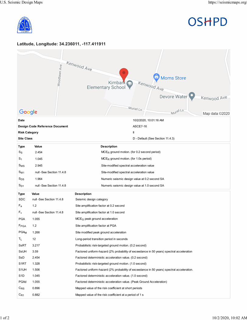
Latitude, Longitude: 34.236011, -117.411911
Date 10/2/2020, 10:01:16 AM
Design Code Reference Document ASCE7-16
Risk Category II
Site Class D - Default (See Section 11.4.3)
Type Value Description
SS 2.454 MCER ground motion. (for 0.2 second period)
S1 1.045 MCER ground motion. (for 1.0s period)
SMS 2.945 Site-modified spectral acceleration value
SM1 null -See Section 11.4.8 Site-modified spectral acceleration value
SDS 1.964 Numeric seismic design value at 0.2 second SA
SD1 null -See Section 11.4.8 Numeric seismic design value at 1.0 second SA
Type Value Description
SDC null -See Section 11.4.8 Seismic design category
Fa 1.2 Site amplification factor at 0.2 second
Fv null -See Section 11.4.8 Site amplification factor at 1.0 second
PGA 1.055 MCEG peak ground acceleration
FPGA 1.2 Site amplification factor at PGA
PGAM 1.266 Site modified peak ground acceleration
TL 12 Long-period transition period in seconds
SsRT 3.217 Probabilistic risk-targeted ground motion. (0.2 second)
SsUH 3.59 Factored uniform-hazard (2% probability of exceedance in 50 years) spectral acceleration
SsD 2.454 Factored deterministic acceleration value. (0.2 second)
S1RT 1.328 Probabilistic risk-targeted ground motion. (1.0 second)
S1UH 1.506 Factored uniform-hazard (2% probability of exceedance in 50 years) spectral acceleration.
S1D 1.045 Factored deterministic acceleration value. (1.0 second)
PGAd 1.055 Factored deterministic acceleration value. (Peak Ground Acceleration)
CRS 0.896 Mapped value of the risk coefficient at short periods
CR1 0.882 Mapped value of the risk coefficient at a period of 1 s
U.S. Seismic Design Maps https://seismicmaps.org/
1 of 2 10/2/2020, 10:02 AM

DISCLAIMER
While the information presented on this website is believed to be correct, SEAOC /OSHPD and its sponsors and contributors assume no responsibility or
liability for its accuracy. The material presented in this web application should not be used or relied upon for any specific application without competent examination
and verification of its accuracy, suitability and applicability by engineers or other licensed professionals. SEAOC / OSHPD do not intend that the use of this
information replace the sound judgment of such competent professionals, having experience and knowledge in the field of practice, nor to substitute for the
standard of care required of such professionals in interpreting and applying the results of the seismic data provided by this website. Users of the information from
this website assume all liability arising from such use. Use of the output of this website does not imply approval by the governing building code bodies responsible
for building code approval and interpretation for the building site described by latitude/longitude location in the search results of this website.
U.S. Seismic Design Maps https://seismicmaps.org/
2 of 2 10/2/2020, 10:02 AM

APPENDIX E

18021 West Kenwood Ave, San Bernardino, Ca.Project No. 20229-01
GeoMat C:\Users\Abdullah\OneDrive - Geomat Testing Laboratories\GeoMat Reports\ANNUAL REPORTS\2020 REPORTS\20229.San Bernardino Kimbark Elementary School\Geostatse 2\Proposed.gsd
Spencer Method
PLATE C.2
0 12 25 37 50 62 75 87 10080
92
105
117
130
142
80
92
105
117
130
142
GEOSTASE® by GREGORY GEOTECHNICAL SOFTWARE
GEOSTASE FS = 3.476
GEOSTASE® by GREGORY GEOTECHNICAL SOFTWARE
B 1 B 2 B 3 B 4 B 5 B 6
B 7
B 8 B 9 B 10
B 11 B 12
B 13
B 14 B 15 B 16 B 17 B 18
0 12 25 37 50 62 75 87 10080
92
105
117
130
142
80
92
105
117
130
142No. FS1 3.476 2 3.481 3 3.482 4 3.487 5 3.488 6 3.488 7 3.488 8 3.491 9 3.492 10 3.494
Soil Moist Wt Sat Wt c Phi ru Pconst Piez Surf SoilNo. (pcf) (pcf) (psf) (deg) (ratio) (psf) No. Options1 Silty Sand 120.0 120.0 184.0 34.1 0.000 0.0 0

*** GEOSTASE(R) ***
** GEOSTASE(R) (c)Copyright by Garry H. Gregory, Ph.D., P.E.,D.GE **
** Current Version 4.30.31-Double Precision, August 2019 **
(All Rights Reserved-Unauthorized Use Prohibited)
*********************************************************************************
SLOPE STABILITY ANALYSIS SOFTWARE
Simplified Bishop, Simplified Janbu, or General Equilibrium (GE)
Options.
(Spencer, Morgenstern-Price, USACE, and Lowe & Karafiath)
Including Pier/Pile, Planar Reinf, Nail, Tieback, Line Loads
Applied Forces, Fiber-Reinforced Soil (FRS), Distributed Loads
Nonlinear Undrained Shear Strength, Curved Strength Envelope,
Anisotropic Strengths, Water Surfaces, 3-Stage Rapid Drawdown
2- or 3-Stage Pseudo-Static & Simplified Newmark Seismic Analyses.
*********************************************************************************
Analysis Date: 10/ 6/ 2020
Analysis Time:
Analysis By: GeoMat
Input File Name: C:\Users\Abdullah\OneDrive - Geomat Testing
Laboratories\GeoMat Reports\ANNUAL REPORTS\2020 REPORTS\20229.San Bernardino Kimbark
Elementary School\Geostatse 2\Proposed.gsd
Output File Name: C:\Users\Abdullah\OneDrive - Geomat Testing
Laboratories\GeoMat Reports\ANNUAL REPORTS\2020 REPORTS\20229.San Bernardino Kimbark
Elementary School\Geostatse 2\Proposed.OUT
Unit System: English
PROJECT: 18021 West Kenwood Ave, San Bernardino, Ca.
DESCRIPTION: Project No. 20229-01
BOUNDARY DATA
18 Surface Boundaries

18 Total Boundaries
Boundary X - 1 Y - 1 X - 2 Y - 2 Soil Type
No. (ft) (ft) (ft) (ft) Below Bnd
1 0.000 124.000 10.000 124.000 1
2 10.000 124.000 19.000 124.000 1
3 19.000 124.000 21.000 124.000 1
4 21.000 124.000 23.000 123.000 1
5 23.000 123.000 24.000 122.000 1
6 24.000 122.000 28.000 122.000 1
7 28.000 122.000 34.000 119.000 1
8 34.000 119.000 35.000 118.000 1
9 35.000 118.000 39.000 118.000 1
10 39.000 118.000 45.000 115.000 1
11 45.000 115.000 46.000 115.000 1
12 46.000 115.000 50.000 115.000 1
13 50.000 115.000 57.000 111.000 1
14 57.000 111.000 58.000 111.000 1
15 58.000 111.000 63.000 110.000 1
16 63.000 110.000 66.000 109.000 1
17 66.000 109.000 70.000 109.000 1
18 70.000 109.000 100.000 109.000 1
User Specified X-Origin = 0.000(ft)
User Specified Y-Origin = 80.000(ft)
MOHR-COULOMB SOIL PARAMETERS
1 Type(s) of Soil Defined
Soil Number Moist Saturated Cohesion Friction Pore Pressure
Water Water
and Unit Wt. Unit Wt. Intercept Angle Pressure Constant
Surface Option
Description (pcf) (pcf) (psf) (deg) Ratio(ru) (psf)
No.
1 Silty Sand 120.0 120.0 184.00 34.10 0.000 0.0
0 0
Drained Shear Strength Reduction Factor applied after first stage = 1.0000
TRIAL FAILURE SURFACE DATA
Circular Trial Failure Surfaces Have Been Generated Using A Random
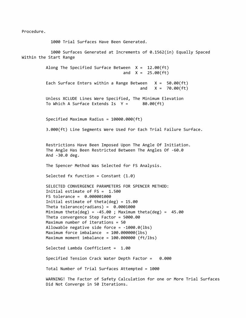
Procedure.
1000 Trial Surfaces Have Been Generated.
1000 Surfaces Generated at Increments of 0.1562(in) Equally Spaced
Within the Start Range
Along The Specified Surface Between X = 12.00(ft)
and X = 25.00(ft)
Each Surface Enters within a Range Between X = 50.00(ft)
and X = 70.00(ft)
Unless XCLUDE Lines Were Specified, The Minimum Elevation
To Which A Surface Extends Is Y = 80.00(ft)
Specified Maximum Radius = 10000.000(ft)
3.000(ft) Line Segments Were Used For Each Trial Failure Surface.
Restrictions Have Been Imposed Upon The Angle Of Initiation.
The Angle Has Been Restricted Between The Angles Of -60.0
And -30.0 deg.
The Spencer Method Was Selected for FS Analysis.
Selected fx function = Constant (1.0)
SELECTED CONVERGENCE PARAMETERS FOR SPENCER METHOD:
Initial estimate of FS = 1.500
FS tolerance = 0.000001000
Initial estimate of theta(deg) = 15.00
Theta tolerance(radians) = 0.0001000
Minimum theta(deg) = -45.00 ; Maximum theta(deg) = 45.00
Theta convergence Step Factor = 5000.00
Maximum number of iterations = 50
Allowable negative side force = -1000.0(lbs)
Maximum force imbalance = 100.000000(lbs)
Maximum moment imbalance = 100.000000 (ft/lbs)
Selected Lambda Coefficient = 1.00
Specified Tension Crack Water Depth Factor = 0.000
Total Number of Trial Surfaces Attempted = 1000
WARNING! The Factor of Safety Calculation for one or More Trial Surfaces
Did Not Converge in 50 Iterations.

Number of Trial Surfaces with Non-Converged FS = 7
Number of Trial Surfaces With Valid FS = 993
Percentage of Trial Surfaces With Non-Converged and/or
Non-Valid FS Solutions of the Total Attempted = 0.7 %
Statistical Data On All Valid FS Values:
FS Max = 5.926 FS Min = 3.476 FS Ave = 3.865
Standard Deviation = 0.327 Coefficient of Variation = 8.47 %
Critical Surface is Sequence Number 287 of Those Analyzed.
*****BEGINNING OF DETAILED GEOSTASE OUTPUT FOR CRITICAL SURFACE FROM A
SEARCH*****
BACK-CALCULATED CIRCULAR SURFACE PARAMETERS:
Circle Center At X = 53.074129(ft) ; Y = 156.875345(ft); and Radius
= 49.730029(ft)
Circular Trial Failure Surface Generated With 20 Coordinate Points
Point X-Coord. Y-Coord.
No. (ft) (ft)
1 15.761 124.000
2 17.811 121.810
3 19.990 119.747
4 22.288 117.820
5 24.699 116.035
6 27.214 114.398
7 29.822 112.916
8 32.515 111.594
9 35.283 110.437
10 38.115 109.448
11 41.002 108.633
12 43.933 107.993
13 46.897 107.530
14 49.884 107.248
15 52.882 107.146
16 55.881 107.225
17 58.870 107.484
18 61.838 107.924
19 64.774 108.541

20 66.447 109.000
Iter. Theta FS FS
No. (deg) (Moment) (Force)
(fx=1.0) Lambda Delta FS
1 -15.0000 3.423701 3.482344 -0.268 0.5864285E-01
2 -19.9500 3.089097 3.561677 -0.363 0.4725792E+00
3 -14.2999 3.511576 3.471689 -0.255 0.3988678E-01
4 -14.7395 3.454409 3.478366 -0.263 0.2395652E-01
5 -14.5745 3.475038 3.475854 -0.260 0.8163818E-03
6 -14.5687 3.475783 3.475766 -0.260 0.1728608E-04
7 -14.5688 3.475767 3.475767 -0.260 0.2830594E-07
Factor Of Safety For The Preceding Specified Surface = 3.476
Theta (fx = 1.0) = -14.57 Deg Lambda = -0.260
The Spencer Method Has Been Selected For Analysis.
Selected fx function = Constant (1.0)
SELECTED CONVERGENCE PARAMETERS FOR ANALYSIS METHOD:
Initial estimate of FS = 1.500
FS tolerance = 0.000001000
Initial estimate of theta(deg) = 15.00
Theta tolerance(radians) = 0.0001000
Minimum theta(deg) = -45.00 ; Maximum theta(deg) = 45.00
Theta convergence Step Factor = 5000.00
Maximum number of iterations = 50
Maximum force imbalance = 100.000000(lbs)
Maximum moment imbalance(if Applicable) = 100.000000 (ft/lbs)
Selected Lambda Coefficient = 1.00
Tension Crack Water Force = 0.00(lbs)
Specified Tension Crack Water Depth Factor = 0.000
Depth of Tension Crack (zo) at Side of First Slice = 0.000(ft)
Depth of Water in Tension Crack = 0.000(ft)
Theoretical Tension Crack Depth = 5.780(ft)
NOTE: In Table 1 following, when a tension crack with water is present on
the

first slice (right facing slope) or on the last slice (left facing slope),
the
"side force" in the tension crack is set equal to the water pressure
resultant.
*** Table 1 - Line of Thrust(if applicable) and Slice Force Data
***
Slice X Y Side Force fx Force Angle
Vert. Shear
No. Coord. Coord. h/H (lbs) (Deg)
Force(lbs)
1 15.76 124.00 0.000 0.00 1.000 0.00
0.0
2 17.81 122.90 0.500 2.11 1.000 -14.57
-0.5
3 19.00 121.12 0.130 133.90 1.000 -14.57
-33.7
4 19.99 120.42 0.158 312.52 1.000 -14.57
-78.6
5 21.00 119.77 0.170 525.16 1.000 -14.57
-132.1
6 22.29 118.96 0.206 845.88 1.000 -14.57
-212.8
7 23.00 118.56 0.223 1009.43 1.000 -14.57
-253.9
8 24.00 118.03 0.270 1236.98 1.000 -14.57
-311.2
9 24.70 117.65 0.271 1400.90 1.000 -14.57
-352.4
10 27.21 116.35 0.257 2018.25 1.000 -14.57
-507.7
11 28.00 115.97 0.251 2207.00 1.000 -14.57
-555.2
12 29.82 115.10 0.268 2664.35 1.000 -14.57
-670.2
13 32.52 113.99 0.294 3196.61 1.000 -14.57
-804.1
14 34.00 113.45 0.308 3404.71 1.000 -14.57
-856.4
15 35.00 113.09 0.341 3536.31 1.000 -14.57
-889.5
16 35.28 112.99 0.338 3571.94 1.000 -14.57
-898.5
17 38.12 112.09 0.309 3808.67 1.000 -14.57
-958.0
18 39.00 111.84 0.300 3837.67 1.000 -14.57
-965.3

19 41.00 111.28 0.316 3901.44 1.000 -14.57
-981.4
20 43.93 110.58 0.343 3806.36 1.000 -14.57
-957.5
21 45.00 110.37 0.354 3710.73 1.000 -14.57
-933.4
22 46.00 110.17 0.341 3621.57 1.000 -14.57
-911.0
23 46.90 109.99 0.330 3540.94 1.000 -14.57
-890.7
24 49.88 109.54 0.295 3090.42 1.000 -14.57
-777.4
25 50.00 109.53 0.294 3065.29 1.000 -14.57
-771.0
26 52.88 109.23 0.336 2485.98 1.000 -14.57
-625.3
27 55.88 109.03 0.409 1845.08 1.000 -14.57
-464.1
28 57.00 108.98 0.452 1603.59 1.000 -14.57
-403.4
29 58.00 108.93 0.425 1403.52 1.000 -14.57
-353.0
30 58.87 108.90 0.423 1235.06 1.000 -14.57
-310.7
31 61.84 108.87 0.409 642.93 1.000 -14.57
-161.7
32 63.00 108.91 0.407 423.60 1.000 -14.57
-106.6
33 64.77 108.97 0.497 164.09 1.000 -14.57
-41.3
34 66.00 109.05 1.000+ 33.80 1.000 -14.57
-8.5
NOTE: A value of 0.000- for h/H indicates that the line of thrust is at or
below
the lower boundary of the sliding mass. A value of 1.000+ for h/H
indicates that
the line of thrust is at or above the upper boundary of the sliding mass.
***Table 2 - Geometry Data on the 34 Slices***
Slice Width Height X-Cntr Y-Cntr-Base Y-Cntr-Top Alpha Beta Base
Length
No. (ft) (ft) (ft) (ft) (ft) (deg) (deg)
(ft)
1 2.05 1.10 16.79 122.90 124.00 -46.89 0.00
3.00

2 1.19 2.75 18.41 121.25 124.00 -43.43 0.00
1.64
3 0.99 3.78 19.49 120.22 124.00 -43.43 0.00
1.36
4 1.01 4.68 20.49 119.32 124.00 -39.98 0.00
1.32
5 1.29 5.32 21.64 118.36 123.68 -39.98 -26.57
1.68
6 0.71 5.62 22.64 117.56 123.18 -36.52 -26.57
0.89
7 1.00 5.58 23.50 116.92 122.50 -36.52 -45.00
1.24
8 0.70 5.71 24.35 116.29 122.00 -36.52 0.00
0.87
9 2.51 6.78 25.96 115.22 122.00 -33.06 0.00
3.00
10 0.79 7.83 27.61 114.17 122.00 -29.60 0.00
0.90
11 1.82 8.11 28.91 113.43 121.54 -29.60 -26.57
2.10
12 2.69 8.16 31.17 112.26 120.42 -26.15 -26.57
3.00
13 1.48 8.09 33.26 111.28 119.37 -22.69 -26.57
1.61
14 1.00 7.74 34.50 110.76 118.50 -22.69 -45.00
1.08
15 0.28 7.50 35.14 110.50 118.00 -22.69 0.00
0.31
16 2.83 8.06 36.70 109.94 118.00 -19.23 0.00
3.00
17 0.88 8.68 38.56 109.32 118.00 -15.78 0.00
0.92
18 2.00 8.58 40.00 108.92 117.50 -15.78 -26.57
2.08
19 2.93 7.95 42.47 108.31 116.27 -12.32 -26.57
3.00
20 1.07 7.36 44.47 107.91 115.27 -8.86 -26.57
1.08
21 1.00 7.25 45.50 107.75 115.00 -8.86 0.00
1.01
22 0.90 7.40 46.45 107.60 115.00 -8.86 0.00
0.91
23 2.99 7.61 48.39 107.39 115.00 -5.41 0.00
3.00
24 0.12 7.75 49.94 107.25 115.00 -1.95 0.00
0.12
25 2.88 6.98 51.44 107.19 114.18 -1.95 -29.74
2.88
26 3.00 5.31 54.38 107.19 112.50 1.51 -29.74
3.00

27 1.12 4.05 56.44 107.27 111.32 4.96 -29.74
1.12
28 1.00 3.63 57.50 107.37 111.00 4.96 0.00
1.00
29 0.87 3.47 58.44 107.45 110.91 4.96 -11.31
0.87
30 2.97 2.83 60.35 107.70 110.53 8.42 -11.31
3.00
31 1.16 2.07 62.42 108.05 110.12 11.88 -11.31
1.19
32 1.77 1.35 63.89 108.35 109.70 11.88 -18.43
1.81
33 1.23 0.50 65.39 108.71 109.20 15.34 -18.43
1.27
34 0.45 0.06 66.22 108.94 109.00 15.34 0.00
0.46
***Table 2A - Coordinates of Slice Points Defining the Slip Surface***
Point X-Pt Y-Pt
No. (ft) (ft)
1 15.760761 124.000000
2 17.810983 121.809888
3 19.000000 120.684209
4 19.989534 119.747386
5 21.000000 118.900236
6 22.288486 117.820000
7 23.000000 117.293148
8 24.000000 116.552681
9 24.699474 116.034744
10 27.213722 114.398114
11 28.000000 113.951358
12 29.822081 112.916068
13 32.515059 111.593998
14 34.000000 110.973108
15 35.000000 110.554984
16 35.282856 110.436715
17 38.115398 109.448431
18 39.000000 109.198496
19 41.002378 108.632743
20 43.933289 107.992620
21 45.000000 107.826278
22 46.000000 107.670339
23 46.897466 107.530390
24 49.884121 107.247735
25 50.000000 107.243791
26 52.882385 107.145686

27 55.881346 107.224612
28 57.000000 107.321783
29 58.000000 107.408647
30 58.870092 107.484226
31 61.837745 107.923585
32 63.000000 108.168052
33 64.773505 108.541088
34 66.000000 108.877431
35 66.446955 109.000000
***Table 3 - Force and Pore Pressure Data On The 34 Slices (Excluding
Reinforcement)***
Ubeta Ubeta Ualpha Earthquake
Force Stress Force Pore Force
Distributed
Slice Weight Top Top Bot Pressure Hor Ver Load
No. (lbs) (lbs) (psf) (lbs) (psf) (lbs) (lbs)
(lbs)
1 269.4 0.0 0.0 0.0 0.0 0.0 0.0
0.00
2 392.8 0.0 0.0 0.0 0.0 0.0 0.0
0.00
3 449.4 0.0 0.0 0.0 0.0 0.0 0.0
0.00
4 567.0 0.0 0.0 0.0 0.0 0.0 0.0
0.00
5 822.2 0.0 0.0 0.0 0.0 0.0 0.0
0.00
6 480.0 0.0 0.0 0.0 0.0 0.0 0.0
0.00
7 669.3 0.0 0.0 0.0 0.0 0.0 0.0
0.00
8 479.0 0.0 0.0 0.0 0.0 0.0 0.0
0.00
9 2046.7 0.0 0.0 0.0 0.0 0.0 0.0
0.00
10 738.3 0.0 0.0 0.0 0.0 0.0 0.0
0.00
11 1773.4 0.0 0.0 0.0 0.0 0.0 0.0
0.00
12 2637.2 0.0 0.0 0.0 0.0 0.0 0.0
0.00
13 1441.2 0.0 0.0 0.0 0.0 0.0 0.0
0.00
14 928.3 0.0 0.0 0.0 0.0 0.0 0.0
0.00
15 254.7 0.0 0.0 0.0 0.0 0.0 0.0

0.00
16 2738.8 0.0 0.0 0.0 0.0 0.0 0.0
0.00
17 921.0 0.0 0.0 0.0 0.0 0.0 0.0
0.00
18 2062.6 0.0 0.0 0.0 0.0 0.0 0.0
0.00
19 2797.3 0.0 0.0 0.0 0.0 0.0 0.0
0.00
20 941.8 0.0 0.0 0.0 0.0 0.0 0.0
0.00
21 870.2 0.0 0.0 0.0 0.0 0.0 0.0
0.00
22 796.9 0.0 0.0 0.0 0.0 0.0 0.0
0.00
23 2727.7 0.0 0.0 0.0 0.0 0.0 0.0
0.00
24 107.8 0.0 0.0 0.0 0.0 0.0 0.0
0.00
25 2414.9 0.0 0.0 0.0 0.0 0.0 0.0
0.00
26 1911.3 0.0 0.0 0.0 0.0 0.0 0.0
0.00
27 543.2 0.0 0.0 0.0 0.0 0.0 0.0
0.00
28 436.2 0.0 0.0 0.0 0.0 0.0 0.0
0.00
29 361.9 0.0 0.0 0.0 0.0 0.0 0.0
0.00
30 1006.1 0.0 0.0 0.0 0.0 0.0 0.0
0.00
31 288.8 0.0 0.0 0.0 0.0 0.0 0.0
0.00
32 287.3 0.0 0.0 0.0 0.0 0.0 0.0
0.00
33 72.9 0.0 0.0 0.0 0.0 0.0 0.0
0.00
34 3.3 0.0 0.0 0.0 0.0 0.0 0.0
0.00
TOTAL WEIGHT OF SLIDING MASS = 35238.67(lbs)
EFFECTIVE WEIGHT OF SLIDING MASS = 35238.67(lbs)
TOTAL AREA OF SLIDING MASS = 293.66(ft2)
***TABLE 4 - SOIL STRENGTH & SOIL OPTIONS DATA ON THE 34 SLICES***
Slice Soil Cohesion Phi(Deg) Options
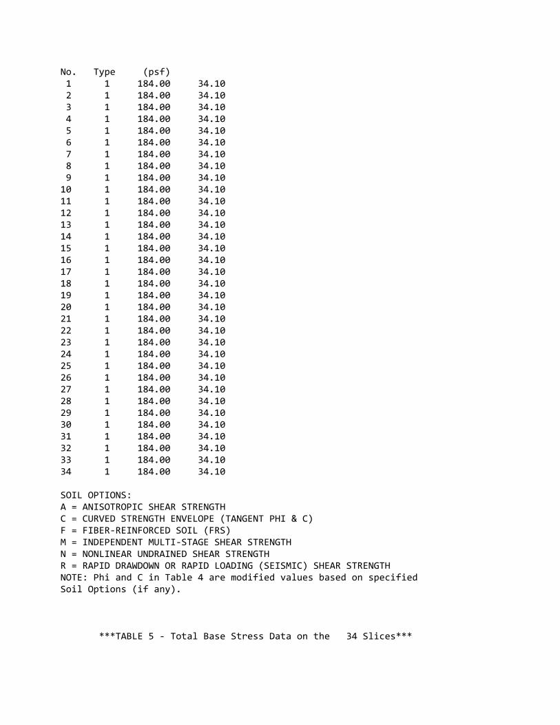
No. Type (psf)
1 1 184.00 34.10
2 1 184.00 34.10
3 1 184.00 34.10
4 1 184.00 34.10
5 1 184.00 34.10
6 1 184.00 34.10
7 1 184.00 34.10
8 1 184.00 34.10
9 1 184.00 34.10
10 1 184.00 34.10
11 1 184.00 34.10
12 1 184.00 34.10
13 1 184.00 34.10
14 1 184.00 34.10
15 1 184.00 34.10
16 1 184.00 34.10
17 1 184.00 34.10
18 1 184.00 34.10
19 1 184.00 34.10
20 1 184.00 34.10
21 1 184.00 34.10
22 1 184.00 34.10
23 1 184.00 34.10
24 1 184.00 34.10
25 1 184.00 34.10
26 1 184.00 34.10
27 1 184.00 34.10
28 1 184.00 34.10
29 1 184.00 34.10
30 1 184.00 34.10
31 1 184.00 34.10
32 1 184.00 34.10
33 1 184.00 34.10
34 1 184.00 34.10
SOIL OPTIONS:
A = ANISOTROPIC SHEAR STRENGTH
C = CURVED STRENGTH ENVELOPE (TANGENT PHI & C)
F = FIBER-REINFORCED SOIL (FRS)
M = INDEPENDENT MULTI-STAGE SHEAR STRENGTH
N = NONLINEAR UNDRAINED SHEAR STRENGTH
R = RAPID DRAWDOWN OR RAPID LOADING (SEISMIC) SHEAR STRENGTH
NOTE: Phi and C in Table 4 are modified values based on specified
Soil Options (if any).
***TABLE 5 - Total Base Stress Data on the 34 Slices***

Slice Alpha X-Coord. Base Total Total Total
No. (deg) Slice Cntr Leng. Normal Stress Vert. Stress
Normal/Vert.
* (ft) (ft) (psf) (psf) Stress
Ratio
1 -46.89 16.79 3.00 61.75 131.41
0.470
2 -43.43 18.41 1.64 213.06 330.35
0.645
3 -43.43 19.49 1.36 302.75 454.10
0.667
4 -39.98 20.49 1.32 398.71 561.14
0.711
5 -39.98 21.64 1.68 456.58 638.13
0.715
6 -36.52 22.64 0.89 504.73 674.56
0.748
7 -36.52 23.50 1.24 500.61 669.25
0.748
8 -36.52 24.35 0.87 512.66 684.75
0.749
9 -33.06 25.96 3.00 637.03 814.03
0.783
10 -29.60 27.61 0.90 764.01 939.03
0.814
11 -29.60 28.91 2.10 792.38 973.29
0.814
12 -26.15 31.17 3.00 824.71 979.28
0.842
13 -22.69 33.26 1.61 844.36 970.52
0.870
14 -22.69 34.50 1.08 807.32 928.31
0.870
15 -22.69 35.14 0.31 782.91 900.50
0.869
16 -19.23 36.70 3.00 868.38 966.89
0.898
17 -15.78 38.56 0.92 964.88 1041.18
0.927
18 -15.78 40.00 2.08 954.55 1030.05
0.927
19 -12.32 42.47 3.00 912.20 954.41
0.956
20 -8.86 44.47 1.08 870.71 882.87
0.986
21 -8.86 45.50 1.01 858.30 870.20
0.986
22 -8.86 46.45 0.91 875.70 887.96
0.986

23 -5.41 48.39 3.00 929.12 913.31
1.017
24 -1.95 49.94 0.12 976.80 930.51
1.050
25 -1.95 51.44 2.88 880.72 837.81
1.051
26 1.51 54.38 3.00 696.03 637.31
1.092
27 4.96 56.44 1.12 553.84 485.57
1.141
28 4.96 57.50 1.00 499.55 436.17
1.145
29 4.96 58.44 0.87 477.36 415.99
1.148
30 8.42 60.35 3.00 408.85 339.04
1.206
31 11.88 62.42 1.19 320.17 248.45
1.289
32 11.88 63.89 1.81 218.89 161.98
1.351
33 15.34 65.39 1.27 106.34 59.42
1.790
34 15.34 66.22 0.46 43.20 7.35
5.875
***TABLE 5A - Total Base Force Data on the 34 Slices***
Slice Alpha X-Coord. Base Total Total Total
No. (deg) Slice Cntr Leng. Normal Force Vert. Force
Normal/Vert.
* (ft) (ft) (lbs) (lbs) Force
Ratio
1 -46.89 16.79 3.00 185.25 269.41
0.688
2 -43.43 18.41 1.64 348.86 392.80
0.888
3 -43.43 19.49 1.36 412.54 449.35
0.918
4 -39.98 20.49 1.32 525.74 567.02
0.927
5 -39.98 21.64 1.68 767.69 822.22
0.934
6 -36.52 22.64 0.89 446.86 479.96
0.931
7 -36.52 23.50 1.24 622.91 669.25
0.931
8 -36.52 24.35 0.87 446.20 478.97
0.932

9 -33.06 25.96 3.00 1911.09 2046.67
0.934
10 -29.60 27.61 0.90 690.92 738.34
0.936
11 -29.60 28.91 2.10 1660.55 1773.42
0.936
12 -26.15 31.17 3.00 2474.13 2637.18
0.938
13 -22.69 33.26 1.61 1359.02 1441.17
0.943
14 -22.69 34.50 1.08 875.05 928.31
0.943
15 -22.69 35.14 0.31 240.03 254.71
0.942
16 -19.23 36.70 3.00 2605.14 2738.76
0.951
17 -15.78 38.56 0.92 886.95 921.03
0.963
18 -15.78 40.00 2.08 1986.20 2062.56
0.963
19 -12.32 42.47 3.00 2736.60 2797.29
0.978
20 -8.86 44.47 1.08 940.03 941.76
0.998
21 -8.86 45.50 1.01 868.67 870.20
0.998
22 -8.86 46.45 0.91 795.41 796.91
0.998
23 -5.41 48.39 3.00 2787.35 2727.75
1.022
24 -1.95 49.94 0.12 113.26 107.83
1.050
25 -1.95 51.44 2.88 2540.05 2414.88
1.052
26 1.51 54.38 3.00 2088.09 1911.27
1.093
27 4.96 56.44 1.12 621.89 543.18
1.145
28 4.96 57.50 1.00 501.43 436.17
1.150
29 4.96 58.44 0.87 416.92 361.95
1.152
30 8.42 60.35 3.00 1226.56 1006.15
1.219
31 11.88 62.42 1.19 380.26 288.76
1.317
32 11.88 63.89 1.81 396.70 287.28
1.381
33 15.34 65.39 1.27 135.24 72.88
1.856

34 15.34 66.22 0.46 20.02 3.29
6.092
***TABLE 6 - Effective and Base Shear Stress Data on the 34 Slices***
Slice Alpha X-Coord. Base Effective Available
Mobilized
No. (deg) Slice Cntr Leng. Normal Stress Shear Strength Shear
Stress
* (ft) (ft) (psf) (psf) (psf)
1 -46.89 16.79 3.00 61.75 225.81
64.97
2 -43.43 18.41 1.64 213.06 328.26
94.44
3 -43.43 19.49 1.36 302.75 388.98
111.91
4 -39.98 20.49 1.32 398.71 453.95
130.60
5 -39.98 21.64 1.68 456.58 493.12
141.88
6 -36.52 22.64 0.89 504.73 525.73
151.26
7 -36.52 23.50 1.24 500.61 522.94
150.45
8 -36.52 24.35 0.87 512.66 531.10
152.80
9 -33.06 25.96 3.00 637.03 615.30
177.03
10 -29.60 27.61 0.90 764.01 701.27
201.76
11 -29.60 28.91 2.10 792.38 720.48
207.29
12 -26.15 31.17 3.00 824.71 742.37
213.58
13 -22.69 33.26 1.61 844.36 755.68
217.41
14 -22.69 34.50 1.08 807.32 730.60
210.20
15 -22.69 35.14 0.31 782.91 714.07
205.44
16 -19.23 36.70 3.00 868.38 771.94
222.09
17 -15.78 38.56 0.92 964.88 837.27
240.89
18 -15.78 40.00 2.08 954.55 830.28
238.88
19 -12.32 42.47 3.00 912.20 801.60
230.63

20 -8.86 44.47 1.08 870.71 773.52
222.55
21 -8.86 45.50 1.01 858.30 765.11
220.13
22 -8.86 46.45 0.91 875.70 776.90
223.52
23 -5.41 48.39 3.00 929.12 813.06
233.92
24 -1.95 49.94 0.12 976.80 845.34
243.21
25 -1.95 51.44 2.88 880.72 780.29
224.50
26 1.51 54.38 3.00 696.03 655.25
188.52
27 4.96 56.44 1.12 553.84 558.98
160.82
28 4.96 57.50 1.00 499.55 522.22
150.25
29 4.96 58.44 0.87 477.36 507.20
145.92
30 8.42 60.35 3.00 408.85 460.82
132.58
31 11.88 62.42 1.19 320.17 400.77
115.30
32 11.88 63.89 1.81 218.89 332.20
95.58
33 15.34 65.39 1.27 106.34 256.00
73.65
34 15.34 66.22 0.46 43.20 213.25
61.35
***TABLE 6A - Effective and Base Shear Force Data on the 34 Slices***
Slice Alpha X-Coord. Base Effective Available
Mobilized
No. (deg) Slice Cntr Leng. Normal Force Shear Force Shear
Force
* (ft) (ft) (lbs) (lbs)
(lbs)
1 -46.89 16.79 3.00 185.25 677.42
194.90
2 -43.43 18.41 1.64 348.86 537.47
154.63
3 -43.43 19.49 1.36 412.54 530.04
152.50
4 -39.98 20.49 1.32 525.74 598.58
172.21
5 -39.98 21.64 1.68 767.69 829.14

238.55
6 -36.52 22.64 0.89 446.86 465.45
133.91
7 -36.52 23.50 1.24 622.91 650.69
187.21
8 -36.52 24.35 0.87 446.20 462.25
132.99
9 -33.06 25.96 3.00 1911.09 1845.91
531.08
10 -29.60 27.61 0.90 690.92 634.19
182.46
11 -29.60 28.91 2.10 1660.55 1509.88
434.40
12 -26.15 31.17 3.00 2474.13 2227.11
640.75
13 -22.69 33.26 1.61 1359.02 1216.28
349.93
14 -22.69 34.50 1.08 875.05 791.89
227.83
15 -22.69 35.14 0.31 240.03 218.92
62.99
16 -19.23 36.70 3.00 2605.14 2315.81
666.27
17 -15.78 38.56 0.92 886.95 769.65
221.43
18 -15.78 40.00 2.08 1986.20 1727.62
497.05
19 -12.32 42.47 3.00 2736.60 2404.81
691.88
20 -8.86 44.47 1.08 940.03 835.09
240.26
21 -8.86 45.50 1.01 868.67 774.36
222.79
22 -8.86 46.45 0.91 795.41 705.66
203.02
23 -5.41 48.39 3.00 2787.35 2439.18
701.77
24 -1.95 49.94 0.12 113.26 98.01
28.20
25 -1.95 51.44 2.88 2540.05 2250.41
647.46
26 1.51 54.38 3.00 2088.09 1965.74
565.56
27 4.96 56.44 1.12 621.89 627.66
180.58
28 4.96 57.50 1.00 501.43 524.19
150.81
29 4.96 58.44 0.87 416.92 442.97
127.45
30 8.42 60.35 3.00 1226.56 1382.45

397.74
31 11.88 62.42 1.19 380.26 475.99
136.95
32 11.88 63.89 1.81 396.70 602.05
173.21
33 15.34 65.39 1.27 135.24 325.57
93.67
34 15.34 66.22 0.46 20.02 98.83
28.43
Average Effective Normal Stress = 628.2132(psf)
Average Available Shear Strength = 609.3323(psf)
Total Length of Failure Surface = 55.7352(ft)
SUM OF MOMENTS = -0.563805E-04 (ft/lbs);Imbalance (Fraction of Total Weight) =
-0.1599960E-08
SUM OF FORCES = -.314786E-04 (lbs);Imbalance (Fraction of Total Weight) =
-0.8932980E-09
Sum of Available Shear Forces = 33961.28(lbs)
Sum of Mobilized Shear Forces = 9770.87(lbs)
FS Balance Check: FS = 3.475767
**** END OF GEOSTASE OUTPUT ****

18021 West Kenwood Ave, San Bernardino, Ca.Project No. 20229-01
GeoMat \Proposed Seismic.gsd
Spencer Method
PLATE C.2
0 12 25 37 50 62 75 87 10090
102
115
127
140
152
90
102
115
127
140
152
GEOSTASE® by GREGORY GEOTECHNICAL SOFTWARE
GEOSTASE FS = 1.283
kh = 0.47300
GEOSTASE® by GREGORY GEOTECHNICAL SOFTWARE
B 1 B 2 B 3 B 4 B 5 B 6
B 7
B 8 B 9 B 10
B 11 B 12
B 13
B 14 B 15 B 16 B 17 B 18
0 12 25 37 50 62 75 87 10090
102
115
127
140
152
90
102
115
127
140
152No. FS1 1.283 2 1.284 3 1.284 4 1.285 5 1.285 6 1.285 7 1.287 8 1.288 9 1.288 10 1.289
Soil Moist Wt Sat Wt c Phi ru Pconst Piez Surf SoilNo. (pcf) (pcf) (psf) (deg) (ratio) (psf) No. Options1 Silty Sand 120.0 120.0 184.0 34.1 0.000 0.0 0

*** GEOSTASE(R) ***
** GEOSTASE(R) (c)Copyright by Garry H. Gregory, Ph.D., P.E.,D.GE **
** Current Version 4.30.31-Double Precision, August 2019 **
(All Rights Reserved-Unauthorized Use Prohibited)
*********************************************************************************
SLOPE STABILITY ANALYSIS SOFTWARE
Simplified Bishop, Simplified Janbu, or General Equilibrium (GE)
Options.
(Spencer, Morgenstern-Price, USACE, and Lowe & Karafiath)
Including Pier/Pile, Planar Reinf, Nail, Tieback, Line Loads
Applied Forces, Fiber-Reinforced Soil (FRS), Distributed Loads
Nonlinear Undrained Shear Strength, Curved Strength Envelope,
Anisotropic Strengths, Water Surfaces, 3-Stage Rapid Drawdown
2- or 3-Stage Pseudo-Static & Simplified Newmark Seismic Analyses.
*********************************************************************************
Analysis Date: 10/ 6/ 2020
Analysis Time:
Analysis By: GeoMat
Input File Name: C:\Users\Abdullah\OneDrive - Geomat Testing
Laboratories\GeoMat Reports\ANNUAL REPORTS\2020 REPORTS\20229.San Bernardino Kimbark
Elementary School\Geostatse 2\Proposed Seismic.gsd
Output File Name: C:\Users\Abdullah\OneDrive - Geomat Testing
Laboratories\GeoMat Reports\ANNUAL REPORTS\2020 REPORTS\20229.San Bernardino Kimbark
Elementary School\Geostatse 2\Proposed Seismic.OUT
Unit System: English
PROJECT: 18021 West Kenwood Ave, San Bernardino, Ca.
DESCRIPTION: Project No. 20229-01
BOUNDARY DATA
18 Surface Boundaries

18 Total Boundaries
Boundary X - 1 Y - 1 X - 2 Y - 2 Soil Type
No. (ft) (ft) (ft) (ft) Below Bnd
1 0.000 124.000 10.000 124.000 1
2 10.000 124.000 19.000 124.000 1
3 19.000 124.000 21.000 124.000 1
4 21.000 124.000 23.000 123.000 1
5 23.000 123.000 24.000 122.000 1
6 24.000 122.000 28.000 122.000 1
7 28.000 122.000 34.000 119.000 1
8 34.000 119.000 35.000 118.000 1
9 35.000 118.000 39.000 118.000 1
10 39.000 118.000 45.000 115.000 1
11 45.000 115.000 46.000 115.000 1
12 46.000 115.000 50.000 115.000 1
13 50.000 115.000 57.000 111.000 1
14 57.000 111.000 58.000 111.000 1
15 58.000 111.000 63.000 110.000 1
16 63.000 110.000 66.000 109.000 1
17 66.000 109.000 70.000 109.000 1
18 70.000 109.000 100.000 109.000 1
User Specified X-Origin = 0.000(ft)
User Specified Y-Origin = 90.000(ft)
MOHR-COULOMB SOIL PARAMETERS
1 Type(s) of Soil Defined
Soil Number Moist Saturated Cohesion Friction Pore Pressure
Water Water
and Unit Wt. Unit Wt. Intercept Angle Pressure Constant
Surface Option
Description (pcf) (pcf) (psf) (deg) Ratio(ru) (psf)
No.
1 Silty Sand 120.0 120.0 184.00 34.10 0.000 0.0
0 0
Drained Shear Strength Reduction Factor applied after first stage = 1.0000
SEISMIC (EARTHQUAKE) DATA
Specified Peak Ground Acceleration Coefficient (PGA) = 0.000(g)
Default Velocity = 0.000(ft) per second

Specified Horizontal Earthquake Coefficient (kh) = -.47300(g)
Specified Vertical Earthquake Coefficient (kv) = 0.000(g)
(NOTE:Input Velocity = 0.0 will result in default Peak
Velocity = 2 times(PGA) times 2.5 fps or 0.762 mps)
Specified Seismic Pore-Pressure Factor = 0.000
Horizontal Seismic Force is Applied at Center of Gravity of Slices
TRIAL FAILURE SURFACE DATA
Circular Trial Failure Surfaces Have Been Generated Using A Random
Procedure.
1000 Trial Surfaces Have Been Generated.
1000 Surfaces Generated at Increments of 0.3003(in) Equally Spaced
Within the Start Range
Along The Specified Surface Between X = 0.00(ft)
and X = 25.00(ft)
Each Surface Enters within a Range Between X = 50.00(ft)
and X = 70.00(ft)
Unless XCLUDE Lines Were Specified, The Minimum Elevation
To Which A Surface Extends Is Y = 90.00(ft)
Specified Maximum Radius = 10000.000(ft)
3.000(ft) Line Segments Were Used For Each Trial Failure Surface.
Restrictions Have Been Imposed Upon The Angle Of Initiation.
The Angle Has Been Restricted Between The Angles Of -60.0
And -30.0 deg.
The Spencer Method Was Selected for FS Analysis.
Selected fx function = Constant (1.0)
SELECTED CONVERGENCE PARAMETERS FOR SPENCER METHOD:
Initial estimate of FS = 1.500
FS tolerance = 0.000001000
Initial estimate of theta(deg) = 15.00
Theta tolerance(radians) = 0.0001000
Minimum theta(deg) = -45.00 ; Maximum theta(deg) = 45.00
Theta convergence Step Factor = 5000.00
Maximum number of iterations = 50
Allowable negative side force = -1000.0(lbs)

Maximum force imbalance = 100.000000(lbs)
Maximum moment imbalance = 100.000000 (ft/lbs)
Selected Lambda Coefficient = 1.00
Specified Tension Crack Water Depth Factor = 0.000
Total Number of Trial Surfaces Attempted = 1000
Number of Trial Surfaces With Valid FS = 1000
Statistical Data On All Valid FS Values:
FS Max = 2.695 FS Min = 1.283 FS Ave = 1.465
Standard Deviation = 0.129 Coefficient of Variation = 8.83 %
Critical Surface is Sequence Number 282 of Those Analyzed.
*****BEGINNING OF DETAILED GEOSTASE OUTPUT FOR CRITICAL SURFACE FROM A
SEARCH*****
BACK-CALCULATED CIRCULAR SURFACE PARAMETERS:
Circle Center At X = 51.794006(ft) ; Y = 176.274798(ft); and Radius
= 68.804426(ft)
Circular Trial Failure Surface Generated With 23 Coordinate Points
Point X-Coord. Y-Coord.
No. (ft) (ft)
1 7.057 124.000
2 9.378 122.100
3 11.780 120.302
4 14.258 118.611
5 16.808 117.030
6 19.423 115.561
7 22.101 114.207
8 24.835 112.972
9 27.620 111.857
10 30.451 110.864
11 33.322 109.996
12 36.229 109.254
13 39.165 108.639
14 42.126 108.153
15 45.104 107.796
16 48.096 107.570
17 51.094 107.474

18 54.094 107.509
19 57.090 107.674
20 60.075 107.971
21 63.045 108.396
22 65.993 108.951
23 66.201 109.000
Iter. Theta FS FS
No. (deg) (Moment) (Force)
(fx=1.0) Lambda Delta FS
1 -15.0000 1.933293 1.228820 -0.268 0.7044728E+00
2 -19.9500 1.516537 1.243255 -0.363 0.2732826E+00
3 -23.0856 1.405285 1.253790 -0.426 0.1514950E+00
4 -26.9847 1.323050 1.268902 -0.509 0.5414817E-01
5 -29.1523 1.292366 1.278528 -0.558 0.1383761E-01
6 -29.8958 1.283569 1.282072 -0.575 0.1496761E-02
7 -29.9858 1.282557 1.282511 -0.577 0.4605246E-04
8 -29.9887 1.282525 1.282525 -0.577 0.2395647E-06
Factor Of Safety For The Preceding Specified Surface = 1.283
Theta (fx = 1.0) = -29.99 Deg Lambda = -0.577
The Spencer Method Has Been Selected For Analysis.
Selected fx function = Constant (1.0)
SELECTED CONVERGENCE PARAMETERS FOR ANALYSIS METHOD:
Initial estimate of FS = 1.500
FS tolerance = 0.000001000
Initial estimate of theta(deg) = 15.00
Theta tolerance(radians) = 0.0001000
Minimum theta(deg) = -45.00 ; Maximum theta(deg) = 45.00
Theta convergence Step Factor = 5000.00
Maximum number of iterations = 50
Maximum force imbalance = 100.000000(lbs)
Maximum moment imbalance(if Applicable) = 100.000000 (ft/lbs)
Selected Lambda Coefficient = 1.00
Tension Crack Water Force = 0.00(lbs)
Specified Tension Crack Water Depth Factor = 0.000
Depth of Tension Crack (zo) at Side of First Slice = 0.000(ft)

Depth of Water in Tension Crack = 0.000(ft)
Theoretical Tension Crack Depth = 5.780(ft)
NOTE: In Table 1 following, when a tension crack with water is present on
the
first slice (right facing slope) or on the last slice (left facing slope),
the
"side force" in the tension crack is set equal to the water pressure
resultant.
*** Table 1 - Line of Thrust(if applicable) and Slice Force Data
***
Slice X Y Side Force fx Force Angle
Vert. Shear
No. Coord. Coord. h/H (lbs) (Deg)
Force(lbs)
1 7.06 124.00 0.000 0.00 1.000 0.00
0.0
2 9.38 123.05 0.500 -216.45 1.000 -29.99
108.2
3 10.00 122.26 0.266 -215.74 1.000 -29.99
107.8
4 11.78 116.16 0.000- -85.50 1.000 -29.99
42.7
5 14.26 124.38 1.000+ 358.15 1.000 -29.99
-179.0
6 16.81 122.00 0.713 1073.29 1.000 -29.99
-536.5
7 19.00 120.91 0.623 1843.00 1.000 -29.99
-921.2
8 19.42 120.71 0.610 2012.80 1.000 -29.99
-1006.1
9 21.00 120.12 0.580 2639.34 1.000 -29.99
-1319.2
10 22.10 119.68 0.592 3104.93 1.000 -29.99
-1551.9
11 23.00 119.35 0.604 3445.02 1.000 -29.99
-1721.9
12 24.00 118.94 0.646 3805.73 1.000 -29.99
-1902.2
13 24.83 118.58 0.621 4102.55 1.000 -29.99
-2050.6
14 27.62 117.59 0.565 5080.12 1.000 -29.99
-2539.2
15 28.00 117.48 0.561 5205.20 1.000 -29.99
-2601.7

16 30.45 116.71 0.590 5997.20 1.000 -29.99
-2997.6
17 33.32 115.79 0.620 6694.34 1.000 -29.99
-3346.0
18 34.00 115.58 0.628 6807.00 1.000 -29.99
-3402.3
19 35.00 115.25 0.674 6956.18 1.000 -29.99
-3476.9
20 36.23 114.82 0.637 7129.63 1.000 -29.99
-3563.6
21 39.00 114.05 0.577 7386.58 1.000 -29.99
-3692.0
22 39.17 114.01 0.579 7403.27 1.000 -29.99
-3700.4
23 42.13 113.28 0.619 7446.49 1.000 -29.99
-3722.0
24 45.00 112.54 0.658 7215.74 1.000 -29.99
-3606.6
25 45.10 112.51 0.655 7206.46 1.000 -29.99
-3602.0
26 46.00 112.31 0.630 7060.74 1.000 -29.99
-3529.2
27 48.10 111.85 0.577 6721.39 1.000 -29.99
-3359.5
28 50.00 111.60 0.546 6249.07 1.000 -29.99
-3123.5
29 51.09 111.45 0.576 5978.43 1.000 -29.99
-2988.2
30 54.09 111.04 0.685 4995.43 1.000 -29.99
-2496.9
31 57.00 110.53 0.860 3900.38 1.000 -29.99
-1949.5
32 57.09 110.51 0.853 3868.84 1.000 -29.99
-1933.8
33 58.00 110.36 0.802 3482.54 1.000 -29.99
-1740.7
34 60.07 109.99 0.774 2633.32 1.000 -29.99
-1316.2
35 63.00 109.56 0.728 1338.96 1.000 -29.99
-669.3
36 63.04 109.56 0.730 1320.63 1.000 -29.99
-660.1
37 65.99 109.09 1.000+ 83.71 1.000 -29.99
-41.8
38 66.00 109.09 1.000+ 80.79 1.000 -29.99
-40.4
NOTE: A value of 0.000- for h/H indicates that the line of thrust is at or
below
the lower boundary of the sliding mass. A value of 1.000+ for h/H

indicates that
the line of thrust is at or above the upper boundary of the sliding mass.
***Table 2 - Geometry Data on the 38 Slices***
Slice Width Height X-Cntr Y-Cntr-Base Y-Cntr-Top Alpha Beta Base
Length
No. (ft) (ft) (ft) (ft) (ft) (deg) (deg)
(ft)
1 2.32 0.95 8.22 123.05 124.00 -39.31 0.00
3.00
2 0.62 2.13 9.69 121.87 124.00 -36.81 0.00
0.78
3 1.78 3.03 10.89 120.97 124.00 -36.81 0.00
2.22
4 2.48 4.54 13.02 119.46 124.00 -34.31 0.00
3.00
5 2.55 6.18 15.53 117.82 124.00 -31.81 0.00
3.00
6 2.19 7.59 17.90 116.41 124.00 -29.31 0.00
2.51
7 0.42 8.32 19.21 115.68 124.00 -29.31 0.00
0.49
8 1.58 8.84 20.21 115.16 124.00 -26.82 0.00
1.77
9 1.10 9.24 21.55 114.49 123.72 -26.82 -26.57
1.23
10 0.90 9.22 22.55 114.00 123.22 -24.32 -26.57
0.99
11 1.00 8.92 23.50 113.58 122.50 -24.32 -45.00
1.10
12 0.83 8.84 24.42 113.16 122.00 -24.32 0.00
0.92
13 2.79 9.59 26.23 112.41 122.00 -21.82 0.00
3.00
14 0.38 10.21 27.81 111.79 122.00 -19.32 0.00
0.40
15 2.45 10.09 29.23 111.29 121.39 -19.32 -26.57
2.60
16 2.87 9.63 31.89 110.43 120.06 -16.82 -26.57
3.00
17 0.68 9.26 33.66 109.91 119.17 -14.32 -26.57
0.70
18 1.00 8.80 34.50 109.70 118.50 -14.32 -45.00
1.03
19 1.23 8.59 35.61 109.41 118.00 -14.32 0.00
1.27

20 2.77 9.04 37.61 108.96 118.00 -11.83 0.00
2.83
21 0.17 9.30 39.08 108.66 117.96 -11.83 -26.57
0.17
22 2.96 8.78 40.65 108.40 117.18 -9.33 -26.57
3.00
23 2.87 7.74 43.56 107.98 115.72 -6.83 -26.57
2.89
24 0.10 7.20 45.05 107.80 115.00 -6.83 0.00
0.11
25 0.90 7.24 45.55 107.76 115.00 -4.33 0.00
0.90
26 2.10 7.35 47.05 107.65 115.00 -4.33 0.00
2.10
27 1.90 7.46 49.05 107.54 115.00 -1.83 0.00
1.91
28 1.09 7.20 50.55 107.49 114.69 -1.83 -29.74
1.09
29 3.00 6.03 52.59 107.49 113.52 0.67 -29.74
3.00
30 2.91 4.24 55.55 107.59 111.83 3.16 -29.74
2.91
31 0.09 3.33 57.04 107.67 111.00 3.16 0.00
0.09
32 0.91 3.28 57.54 107.72 111.00 5.66 0.00
0.91
33 2.07 2.92 59.04 107.87 110.79 5.66 -11.31
2.09
34 2.93 2.11 61.54 108.18 110.29 8.16 -11.31
2.95
35 0.04 1.60 63.02 108.39 109.99 8.16 -18.43
0.05
36 2.95 0.82 64.52 108.67 109.49 10.66 -18.43
3.00
37 0.01 0.05 66.00 108.95 109.00 13.16 -18.43
0.01
38 0.20 0.02 66.10 108.98 109.00 13.16 0.00
0.21
***Table 2A - Coordinates of Slice Points Defining the Slip Surface***
Point X-Pt Y-Pt
No. (ft) (ft)
1 7.057057 124.000000
2 9.378318 122.099540
3 10.000000 121.634303
4 11.780217 120.302075

5 14.258186 118.611020
6 16.807516 117.029590
7 19.000000 115.798510
8 19.423359 115.560794
9 21.000000 114.763828
10 22.100743 114.207421
11 23.000000 113.801062
12 24.000000 113.349178
13 24.834577 112.972047
14 27.619665 111.857018
15 28.000000 111.723673
16 30.450710 110.864456
17 33.322332 109.996247
18 34.000000 109.823211
19 35.000000 109.567871
20 36.229071 109.254041
21 39.000000 108.673880
22 39.165401 108.639249
23 42.125739 108.153041
24 45.000000 107.808850
25 45.104457 107.796341
26 46.000000 107.728530
27 48.095894 107.569827
28 50.000000 107.508929
29 51.094361 107.473929
30 54.094158 107.508830
31 57.000000 107.669509
32 57.089582 107.674463
33 58.000000 107.764747
34 60.074938 107.970513
35 63.000000 108.390029
36 63.044552 108.396419
37 65.992777 108.951369
38 66.000000 108.953058
39 66.200791 109.000000
***Table 3 - Force and Pore Pressure Data On The 38 Slices (Excluding
Reinforcement)***
Ubeta Ubeta Ualpha Earthquake
Force Stress Force Pore Force
Distributed
Slice Weight Top Top Bot Pressure Hor Ver Load
No. (lbs) (lbs) (psf) (lbs) (psf) (lbs) (lbs)
(lbs)
1 264.7 0.0 0.0 0.0 0.0 -125.2 0.0
0.00
2 159.1 0.0 0.0 0.0 0.0 -75.3 0.0

0.00
3 647.7 0.0 0.0 0.0 0.0 -306.3 0.0
0.00
4 1351.0 0.0 0.0 0.0 0.0 -639.0 0.0
0.00
5 1890.5 0.0 0.0 0.0 0.0 -894.2 0.0
0.00
6 1995.8 0.0 0.0 0.0 0.0 -944.0 0.0
0.00
7 422.7 0.0 0.0 0.0 0.0 -199.9 0.0
0.00
8 1672.1 0.0 0.0 0.0 0.0 -790.9 0.0
0.00
9 1220.4 0.0 0.0 0.0 0.0 -577.2 0.0
0.00
10 995.0 0.0 0.0 0.0 0.0 -470.6 0.0
0.00
11 1071.0 0.0 0.0 0.0 0.0 -506.6 0.0
0.00
12 885.3 0.0 0.0 0.0 0.0 -418.7 0.0
0.00
13 3203.6 0.0 0.0 0.0 0.0 -1515.3 0.0
0.00
14 466.0 0.0 0.0 0.0 0.0 -220.4 0.0
0.00
15 2968.3 0.0 0.0 0.0 0.0 -1404.0 0.0
0.00
16 3317.2 0.0 0.0 0.0 0.0 -1569.0 0.0
0.00
17 753.0 0.0 0.0 0.0 0.0 -356.2 0.0
0.00
18 1056.5 0.0 0.0 0.0 0.0 -499.7 0.0
0.00
19 1266.8 0.0 0.0 0.0 0.0 -599.2 0.0
0.00
20 3004.6 0.0 0.0 0.0 0.0 -1421.2 0.0
0.00
21 184.6 0.0 0.0 0.0 0.0 -87.3 0.0
0.00
22 3119.4 0.0 0.0 0.0 0.0 -1475.5 0.0
0.00
23 2668.8 0.0 0.0 0.0 0.0 -1262.3 0.0
0.00
24 90.2 0.0 0.0 0.0 0.0 -42.7 0.0
0.00
25 777.8 0.0 0.0 0.0 0.0 -367.9 0.0
0.00
26 1848.8 0.0 0.0 0.0 0.0 -874.5 0.0
0.00
27 1704.7 0.0 0.0 0.0 0.0 -806.3 0.0

0.00
28 945.0 0.0 0.0 0.0 0.0 -447.0 0.0
0.00
29 2169.3 0.0 0.0 0.0 0.0 -1026.1 0.0
0.00
30 1478.9 0.0 0.0 0.0 0.0 -699.5 0.0
0.00
31 35.8 0.0 0.0 0.0 0.0 -16.9 0.0
0.00
32 358.4 0.0 0.0 0.0 0.0 -169.5 0.0
0.00
33 728.3 0.0 0.0 0.0 0.0 -344.5 0.0
0.00
34 741.4 0.0 0.0 0.0 0.0 -350.7 0.0
0.00
35 8.6 0.0 0.0 0.0 0.0 -4.0 0.0
0.00
36 290.1 0.0 0.0 0.0 0.0 -137.2 0.0
0.00
37 0.0 0.0 0.0 0.0 0.0 -0.0 0.0
0.00
38 0.6 0.0 0.0 0.0 0.0 -0.3 0.0
0.00
TOTAL WEIGHT OF SLIDING MASS = 45761.68(lbs)
EFFECTIVE WEIGHT OF SLIDING MASS = 45761.68(lbs)
TOTAL AREA OF SLIDING MASS = 381.35(ft2)
***TABLE 4 - SOIL STRENGTH & SOIL OPTIONS DATA ON THE 38 SLICES***
Slice Soil Cohesion Phi(Deg) Options
No. Type (psf)
1 1 184.00 34.10
2 1 184.00 34.10
3 1 184.00 34.10
4 1 184.00 34.10
5 1 184.00 34.10
6 1 184.00 34.10
7 1 184.00 34.10
8 1 184.00 34.10
9 1 184.00 34.10
10 1 184.00 34.10
11 1 184.00 34.10
12 1 184.00 34.10
13 1 184.00 34.10
14 1 184.00 34.10
15 1 184.00 34.10

16 1 184.00 34.10
17 1 184.00 34.10
18 1 184.00 34.10
19 1 184.00 34.10
20 1 184.00 34.10
21 1 184.00 34.10
22 1 184.00 34.10
23 1 184.00 34.10
24 1 184.00 34.10
25 1 184.00 34.10
26 1 184.00 34.10
27 1 184.00 34.10
28 1 184.00 34.10
29 1 184.00 34.10
30 1 184.00 34.10
31 1 184.00 34.10
32 1 184.00 34.10
33 1 184.00 34.10
34 1 184.00 34.10
35 1 184.00 34.10
36 1 184.00 34.10
37 1 184.00 34.10
38 1 184.00 34.10
SOIL OPTIONS:
A = ANISOTROPIC SHEAR STRENGTH
C = CURVED STRENGTH ENVELOPE (TANGENT PHI & C)
F = FIBER-REINFORCED SOIL (FRS)
M = INDEPENDENT MULTI-STAGE SHEAR STRENGTH
N = NONLINEAR UNDRAINED SHEAR STRENGTH
R = RAPID DRAWDOWN OR RAPID LOADING (SEISMIC) SHEAR STRENGTH
NOTE: Phi and C in Table 4 are modified values based on specified
Soil Options (if any).
***TABLE 5 - Total Base Stress Data on the 38 Slices***
Slice Alpha X-Coord. Base Total Total Total
No. (deg) Slice Cntr Leng. Normal Stress Vert. Stress
Normal/Vert.
* (ft) (ft) (psf) (psf) Stress
Ratio
1 -39.31 8.22 3.00 30.15 114.03
0.264
2 -36.81 9.69 0.78 106.11 255.97
0.415
3 -36.81 10.89 2.22 157.62 363.82
0.433

4 -34.31 13.02 3.00 263.05 545.21
0.482
5 -31.81 15.53 3.00 385.96 741.56
0.520
6 -29.31 17.90 2.51 504.69 910.31
0.554
7 -29.31 19.21 0.49 553.38 998.44
0.554
8 -26.82 20.21 1.77 623.10 1060.52
0.588
9 -26.82 21.55 1.23 651.04 1108.70
0.587
10 -24.32 22.55 0.99 688.39 1106.47
0.622
11 -24.32 23.50 1.10 666.80 1070.99
0.623
12 -24.32 24.42 0.92 660.55 1060.73
0.623
13 -21.82 26.23 3.00 757.32 1150.26
0.658
14 -19.32 27.81 0.40 852.66 1225.16
0.696
15 -19.32 29.23 2.60 843.28 1211.19
0.696
16 -16.82 31.89 3.00 854.12 1155.17
0.739
17 -14.32 33.66 0.70 873.67 1111.16
0.786
18 -14.32 34.50 1.03 833.04 1056.54
0.788
19 -14.32 35.61 1.27 813.82 1030.69
0.790
20 -11.83 37.61 2.83 907.62 1084.32
0.837
21 -11.83 39.08 0.17 932.67 1116.25
0.836
22 -9.33 40.65 3.00 941.26 1053.73
0.893
23 -6.83 43.56 2.89 894.89 928.51
0.964
24 -6.83 45.05 0.11 837.95 863.69
0.970
25 -4.33 45.55 0.90 902.88 868.51
1.040
26 -4.33 47.05 2.10 915.57 882.10
1.038
27 -1.83 49.05 1.91 997.82 895.27
1.115
28 -1.83 50.55 1.09 966.22 863.51
1.119

29 0.67 52.59 3.00 894.09 723.14
1.236
30 3.16 55.55 2.91 726.42 508.93
1.427
31 3.16 57.04 0.09 600.83 399.36
1.504
32 5.66 57.54 0.91 654.21 393.65
1.662
33 5.66 59.04 2.09 601.26 350.99
1.713
34 8.16 61.54 2.95 535.79 253.47
2.114
35 8.16 63.02 0.05 452.44 191.92
2.357
36 10.66 64.52 3.00 372.06 98.39
3.782
37 13.16 66.00 0.01 275.98 5.88
46.944
38 13.16 66.10 0.21 270.88 2.82
96.176
***TABLE 5A - Total Base Force Data on the 38 Slices***
Slice Alpha X-Coord. Base Total Total Total
No. (deg) Slice Cntr Leng. Normal Force Vert. Force
Normal/Vert.
* (ft) (ft) (lbs) (lbs) Force
Ratio
1 -39.31 8.22 3.00 90.44 264.69
0.342
2 -36.81 9.69 0.78 82.39 159.13
0.518
3 -36.81 10.89 2.22 350.47 647.67
0.541
4 -34.31 13.02 3.00 789.16 1351.02
0.584
5 -31.81 15.53 3.00 1157.88 1890.49
0.612
6 -29.31 17.90 2.51 1269.02 1995.85
0.636
7 -29.31 19.21 0.49 268.68 422.70
0.636
8 -26.82 20.21 1.77 1100.79 1672.06
0.658
9 -26.82 21.55 1.23 802.98 1220.40
0.658
10 -24.32 22.55 0.99 679.31 995.00
0.683

11 -24.32 23.50 1.10 731.72 1070.99
0.683
12 -24.32 24.42 0.92 604.96 885.26
0.683
13 -21.82 26.23 3.00 2271.96 3203.56
0.709
14 -19.32 27.81 0.40 343.65 465.97
0.737
15 -19.32 29.23 2.60 2189.98 2968.28
0.738
16 -16.82 31.89 3.00 2562.37 3317.20
0.772
17 -14.32 33.66 0.70 611.06 753.00
0.811
18 -14.32 34.50 1.03 859.77 1056.54
0.814
19 -14.32 35.61 1.27 1032.33 1266.79
0.815
20 -11.83 37.61 2.83 2569.48 3004.59
0.855
21 -11.83 39.08 0.17 157.61 184.63
0.854
22 -9.33 40.65 3.00 2823.77 3119.39
0.905
23 -6.83 43.56 2.89 2590.52 2668.79
0.971
24 -6.83 45.05 0.11 88.15 90.22
0.977
25 -4.33 45.55 0.90 810.88 777.79
1.043
26 -4.33 47.05 2.10 1924.42 1848.78
1.041
27 -1.83 49.05 1.91 1900.93 1704.70
1.115
28 -1.83 50.55 1.09 1057.93 944.99
1.120
29 0.67 52.59 3.00 2682.27 2169.28
1.236
30 3.16 55.55 2.91 2114.10 1478.87
1.430
31 3.16 57.04 0.09 53.91 35.78
1.507
32 5.66 57.54 0.91 598.52 358.38
1.670
33 5.66 59.04 2.09 1253.69 728.27
1.721
34 8.16 61.54 2.95 1583.25 741.41
2.135
35 8.16 63.02 0.05 20.36 8.55
2.382

36 10.66 64.52 3.00 1116.19 290.06
3.848
37 13.16 66.00 0.01 2.05 0.04
48.210
38 13.16 66.10 0.21 55.86 0.57
98.769
***TABLE 6 - Effective and Base Shear Stress Data on the 38 Slices***
Slice Alpha X-Coord. Base Effective Available
Mobilized
No. (deg) Slice Cntr Leng. Normal Stress Shear Strength Shear
Stress
* (ft) (ft) (psf) (psf) (psf)
1 -39.31 8.22 3.00 30.15 204.41
159.38
2 -36.81 9.69 0.78 106.11 255.84
199.48
3 -36.81 10.89 2.22 157.62 290.72
226.67
4 -34.31 13.02 3.00 263.05 362.10
282.33
5 -31.81 15.53 3.00 385.96 445.32
347.22
6 -29.31 17.90 2.51 504.69 525.70
409.89
7 -29.31 19.21 0.49 553.38 558.67
435.60
8 -26.82 20.21 1.77 623.10 605.87
472.41
9 -26.82 21.55 1.23 651.04 624.79
487.15
10 -24.32 22.55 0.99 688.39 650.08
506.87
11 -24.32 23.50 1.10 666.80 635.46
495.47
12 -24.32 24.42 0.92 660.55 631.23
492.18
13 -21.82 26.23 3.00 757.32 696.74
543.26
14 -19.32 27.81 0.40 852.66 761.30
593.59
15 -19.32 29.23 2.60 843.28 754.95
588.64
16 -16.82 31.89 3.00 854.12 762.29
594.36
17 -14.32 33.66 0.70 873.67 775.52
604.68

18 -14.32 34.50 1.03 833.04 748.01
583.23
19 -14.32 35.61 1.27 813.82 735.00
573.08
20 -11.83 37.61 2.83 907.62 798.50
622.60
21 -11.83 39.08 0.17 932.67 815.46
635.83
22 -9.33 40.65 3.00 941.26 821.28
640.36
23 -6.83 43.56 2.89 894.89 789.89
615.88
24 -6.83 45.05 0.11 837.95 751.33
585.82
25 -4.33 45.55 0.90 902.88 795.30
620.10
26 -4.33 47.05 2.10 915.57 803.89
626.80
27 -1.83 49.05 1.91 997.82 859.58
670.22
28 -1.83 50.55 1.09 966.22 838.18
653.54
29 0.67 52.59 3.00 894.09 789.34
615.46
30 3.16 55.55 2.91 726.42 675.83
526.95
31 3.16 57.04 0.09 600.83 590.79
460.65
32 5.66 57.54 0.91 654.21 626.93
488.83
33 5.66 59.04 2.09 601.26 591.08
460.87
34 8.16 61.54 2.95 535.79 546.76
426.31
35 8.16 63.02 0.05 452.44 490.33
382.31
36 10.66 64.52 3.00 372.06 435.91
339.88
37 13.16 66.00 0.01 275.98 370.85
289.16
38 13.16 66.10 0.21 270.88 367.40
286.47
***TABLE 6A - Effective and Base Shear Force Data on the 38 Slices***
Slice Alpha X-Coord. Base Effective Available
Mobilized
No. (deg) Slice Cntr Leng. Normal Force Shear Force Shear
Force

* (ft) (ft) (lbs) (lbs)
(lbs)
1 -39.31 8.22 3.00 90.44 613.23
478.15
2 -36.81 9.69 0.78 82.39 198.66
154.90
3 -36.81 10.89 2.22 350.47 646.41
504.01
4 -34.31 13.02 3.00 789.16 1086.30
847.00
5 -31.81 15.53 3.00 1157.88 1335.95
1041.65
6 -29.31 17.90 2.51 1269.02 1321.85
1030.66
7 -29.31 19.21 0.49 268.68 271.25
211.50
8 -26.82 20.21 1.77 1100.79 1070.35
834.56
9 -26.82 21.55 1.23 802.98 770.60
600.84
10 -24.32 22.55 0.99 679.31 641.50
500.19
11 -24.32 23.50 1.10 731.72 697.32
543.71
12 -24.32 24.42 0.92 604.96 578.10
450.75
13 -21.82 26.23 3.00 2271.96 2090.23
1629.78
14 -19.32 27.81 0.40 343.65 306.83
239.24
15 -19.32 29.23 2.60 2189.98 1960.57
1528.68
16 -16.82 31.89 3.00 2562.37 2286.86
1783.09
17 -14.32 33.66 0.70 611.06 542.41
422.92
18 -14.32 34.50 1.03 859.77 772.01
601.95
19 -14.32 35.61 1.27 1032.33 932.35
726.96
20 -11.83 37.61 2.83 2569.48 2260.58
1762.60
21 -11.83 39.08 0.17 157.61 137.80
107.45
22 -9.33 40.65 3.00 2823.77 2463.84
1921.08
23 -6.83 43.56 2.89 2590.52 2286.56
1782.86
24 -6.83 45.05 0.11 88.15 79.04

61.63
25 -4.33 45.55 0.90 810.88 714.26
556.92
26 -4.33 47.05 2.10 1924.42 1689.68
1317.46
27 -1.83 49.05 1.91 1900.93 1637.56
1276.83
28 -1.83 50.55 1.09 1057.93 917.74
715.57
29 0.67 52.59 3.00 2682.27 2368.03
1846.38
30 3.16 55.55 2.91 2114.10 1966.84
1533.57
31 3.16 57.04 0.09 53.91 53.00
41.33
32 5.66 57.54 0.91 598.52 573.57
447.22
33 5.66 59.04 2.09 1253.69 1232.47
960.97
34 8.16 61.54 2.95 1583.25 1615.66
1259.75
35 8.16 63.02 0.05 20.36 22.07
17.21
36 10.66 64.52 3.00 1116.19 1307.72
1019.64
37 13.16 66.00 0.01 2.05 2.75
2.14
38 13.16 66.10 0.21 55.86 75.76
59.07
Average Effective Normal Stress = 651.8026(psf)
Average Available Shear Strength = 625.3035(psf)
Total Length of Failure Surface = 63.2136(ft)
SUM OF MOMENTS = -0.987489E-01 (ft/lbs);Imbalance (Fraction of Total Weight) =
-0.2157894E-05
SUM OF FORCES = -.140345E-02 (lbs);Imbalance (Fraction of Total Weight) =
-0.3066871E-07
Sum of Available Shear Forces = 39527.70(lbs)
Sum of Mobilized Shear Forces = 30820.23(lbs)
FS Balance Check: FS = 1.282525
*** SEISMIC SLOPE DISPLACEMENT DATA ***
(Note: kv is set = zero for displacement calculations)
Seismic Yield Coefficient (ky) = 0.66809(g)
Calculated Newmark Seismic Displacement = 0.000(ft)

Average Elevation of Point of Application of kh on Sliding Mass =
114.584(ft)
Non-Symmetrical Sliding Resistance Has Been Specified
for Downhill Sliding.
**** END OF GEOSTASE OUTPUT ****

1
This report was generated by LimitState:GEO3.5.g.24265 - limitstate.com
About this Report
This report has been generated using LimitState:GEO, a software application capable of directly identifying the critical collapse mechanism for a wide variety of geotechnical stability problems, including those involving slopes, retaining walls, footings etc.
The software utilizes the Discontinuity Layout Optimization (DLO) procedure to obtain a solution (Smith and Gilbert 2007). The main steps involved are: (i) distribution of nodes across the problem domain; (ii) connection of every node to every other node with potential discontinuities (e.g. slip-lines); (iii) application of rigorous optimization techniques to identify the critical subset of potential discontinuities, and hence also the critical failure mechanism and margin of safety.
The accuracy of the DLO solution is controlled by the specified nodal density. Within the set of all possible discontinuities linking pairs of nodes, all potential translational failure mechanisms are considered, whether anticipated or not by the engineer. Failure mechanisms involving rotations along the edges of solid bodies in the problem can also be identified. Thus in this case the solution identified by the DLO procedure is guaranteed to be the most critical solution for the problem posed. This means that there is no need to prescribe any aspect of the collapse mechanism prior to an analysis, or to separately consider different failure modes. The critical mechanism and collapse load factor are determined according to the well established upper bound theorem of plasticity.
LimitState:GEO reports the solution to a problem both visually as a collapse mechanism and numerically in terms of an Adequacy Factor, which is defined as the factor by which specified loads must be increased, or material strengths decreased, in order for the system under consideration to reach a collapse state.
REFERENCE
Smith, C.C. and Gilbert, M. (2007) Application of discontinuity layout optimization to plane plasticity problems, Proceedings of the Royal Society A: Mathematical, Physical and Engineering Sciences, Vol. 463, 2086, pp 2461-2484.
Summary
Name Date of Analysis Name of Engineer Organization
Access Ramp Stability Analysis Mon Oct 5 2020 HMN GeoMat Testing Laboratories, Inc.
Reference # Location Map Reference Tags
Project No. 20229-01 Kimbark Elementary School, San
Bernardino, CA Access Ramp
Comments
Static Condition
Target Nodal Density Nodal Spacing Scale
Factor Water
Model Translational Failures?
Model Rotational Failures?
Seismic Accelerations: Horiz.
/ Vert. (g)
Fine (1000 nodes) 2.06269 Enabled True Along edges None
Scenario Partial Factor Set Short / Long
Term?** Analysis Type Adequacy Factor
1* User Long Term Factor Strength(s) 3.075
*This report provides details of this scenario, which has been identified as the most critical.
**For Mohr Coulomb materials with Drainage Behaviour specified as 'drained/undrained', undrained properties are used in a short term analysis, and drained properties are used in a long term analysis.

2
Failure Mechanism (Scenario 1)
Analysis Options
Factor Strength(s)
Solution Tolerance (%)
Automatic Adequacy on Load(s)
Factor on Load(s) Artificial Cohesion
(kN/m² (kPa))
1 True 1 0.1
Geometry
(all distances in ft)
All Geometrical Objects
No. of Vertices (V) No. of Boundaries (B) No. of Solids (S)
101 114 14
Boundary Objects
ID Start Vertex ID (x, y) End Vertex ID (x, y) Baseline Nodal
Spacing Support Type Material(s)
B1 V1 (14.1076, 124.672) V2 (14.1076, 124.672) 1.64042 Free Frictionless
B2 V2 (14.1076, 124.672) V3 (19.0289, 124.672) 1.64042 Free -
B3 V3 (19.0289, 124.672) V4 (19.0289, 124.672) 1.64042 Free -
B4 V4 (19.0289, 124.672) V6 (19.0289, 124.672) 1.64042 Free -
B6* V1 (14.1076, 124.672) V6 (19.0289, 124.672) 1.64042 Free -
B15 V12 (65.6168,
108.268) V15 (75.4593,
108.268) 1.64042 Free -
B23 V21 (62.336, 108.268) V22 (62.336, 108.268) 1.64042 Free -
B24 V22 (62.336, 108.268) V23 (62.336, 111.549) 1.64042 Free -
B25* V23 (62.336, 111.549) V24 (59.0551,
111.549) 1.64042 Free -

3
B26 V24 (59.0551,
111.549) V25 (59.0551,
111.549) 1.64042 Free -
B27 V25 (59.0551,
111.549) V26 (59.0551,
111.549) 1.64042 Free -
B28 V26 (59.0551,
111.549) V27 (59.0551,
111.549) 1.64042 Free -
B29 V27 (59.0551,
111.549) V28 (55.7743,
111.549) 1.64042 Free -
B30 V28 (55.7743,
111.549) V29 (55.7743,
111.549) 1.64042 Free -
B31 V29 (55.7743,
111.549) V30 (59.0551,
111.549) 1.64042 Free -
B32 V30 (59.0551,
111.549) V31 (59.0551,
111.549) 1.64042 Free -
B33 V31 (59.0551,
111.549) V32 (59.0551,
108.268) 1.64042 Free -
B34 V32 (59.0551,
108.268) V33 (59.0551,
108.268) 1.64042 Free -
B35 V33 (59.0551,
108.268) V34 (59.0551,
108.268) 1.64042 Free -
B36 V34 (59.0551,
108.268) V35 (59.0551,
108.268) 1.64042 Free -
B37 V35 (59.0551,
108.268) V36 (59.0551,
111.549) 1.64042 Free -
B38 V36 (59.0551,
111.549) V37 (62.336, 111.549) 1.64042 Free -
B39 V37 (62.336, 111.549) V38 (62.336, 108.268) 1.64042 Free -
B40 V38 (62.336, 108.268) V39 (62.336, 108.268) 1.64042 Free -
B41 V21 (62.336, 108.268) V39 (62.336, 108.268) 1.64042 Free -
B42 V40 (49.2126,
111.549) V41 (49.2126,
111.549) 1.64042 Free -
B43 V41 (49.2126,
111.549) V42 (49.2126,
114.829) 1.64042 Free -
B44* V42 (49.2126,
114.829) V43 (45.9318,
114.829) 1.64042 Free -
B45 V43 (45.9318,
114.829) V44 (45.9318,
114.829) 1.64042 Free -
B46 V44 (45.9318,
114.829) V45 (45.9318,
114.829) 1.64042 Free -
B47 V45 (45.9318,
114.829) V46 (45.9318,
114.829) 1.64042 Free -
B48 V46 (45.9318,
114.829) V47 (45.9318,
114.829) 1.64042 Free -
B49 V47 (45.9318,
114.829) V48 (45.9318,
111.549) 1.64042 Free -
B50 V48 (45.9318,
111.549) V49 (45.9318,
111.549) 1.64042 Free -
B51 V49 (45.9318,
111.549) V50 (45.9318,
114.829) 1.64042 Free -
B52 V50 (45.9318,
114.829) V51 (45.9318,
114.829) 1.64042 Free -
B53 V51 (45.9318,
114.829) V52 (45.9318,
114.829) 1.64042 Free -
B54 V52 (45.9318,
114.829) V53 (49.2126,
114.829) 1.64042 Free -
B55 V53 (49.2126,
114.829) V54 (49.2126,
111.549) 1.64042 Free -
B56 V54 (49.2126,
111.549) V55 (49.2126,
111.549) 1.64042 Free -
B57 V40 (49.2126,
111.549) V55 (49.2126,
111.549) 1.64042 Free -
B58 V56 (45.9318,
114.829) V47 (45.9318,
114.829) 1.64042 Free -

4
B59 V46 (45.9318,
114.829) V57 (45.9318,
114.829) 1.64042 Free -
B60 V57 (45.9318,
114.829) V58 (45.9318,
114.829) 1.64042 Free -
B61 V58 (45.9318,
114.829) V59 (45.9318,
114.829) 1.64042 Free -
B62 V56 (45.9318,
114.829) V59 (45.9318,
114.829) 1.64042 Free -
B63 V60 (39.3701,
114.829) V61 (39.3701,
114.829) 1.64042 Free -
B64 V61 (39.3701,
114.829) V62 (39.3701, 118.11) 1.64042 Free -
B65* V62 (39.3701, 118.11) V63 (36.0892, 118.11) 1.64042 Free -
B66 V63 (36.0892, 118.11) V64 (36.0892, 118.11) 1.64042 Free -
B67 V64 (36.0892, 118.11) V65 (32.8084, 118.11) 1.64042 Free -
B68 V65 (32.8084, 118.11) V66 (32.8084, 118.11) 1.64042 Free -
B69 V66 (32.8084, 118.11) V67 (32.8084, 118.11) 1.64042 Free -
B70 V67 (32.8084, 118.11) V68 (32.8084,
114.829) 1.64042 Free -
B71 V68 (32.8084,
114.829) V69 (36.0892,
114.829) 1.64042 Free -
B72 V69 (36.0892,
114.829) V70 (36.0892, 118.11) 1.64042 Free -
B73 V70 (36.0892, 118.11) V71 (36.0892, 118.11) 1.64042 Free -
B74 V71 (36.0892, 118.11) V72 (36.0892, 118.11) 1.64042 Free -
B75 V72 (36.0892, 118.11) V73 (39.3701, 118.11) 1.64042 Free -
B76 V73 (39.3701, 118.11) V74 (39.3701, 118.11) 1.64042 Free -
B77 V74 (39.3701, 118.11) V75 (39.3701, 118.11) 1.64042 Free -
B78 V60 (39.3701,
114.829) V75 (39.3701, 118.11) 1.64042 Free -
B79 V76 (32.8084, 118.11) V67 (32.8084, 118.11) 1.64042 Free -
B80 V66 (32.8084, 118.11) V77 (32.8084, 118.11) 1.64042 Free -
B81 V77 (32.8084, 118.11) V78 (32.8084, 118.11) 1.64042 Free -
B82 V78 (32.8084, 118.11) V79 (32.8084, 118.11) 1.64042 Free -
B83 V76 (32.8084, 118.11) V79 (32.8084, 118.11) 1.64042 Free -
B84 V80 (26.9029, 118.11) V81 (28.5433, 118.11) 1.64042 Free -
B85 V81 (28.5433, 118.11) V82 (28.5433,
121.391) 1.64042 Free -
B86* V82 (28.5433,
121.391) V83 (23.9501,
121.391) 1.64042 Free -
B87 V83 (23.9501,
121.391) V84 (23.9501,
121.391) 1.64042 Free -
B88 V84 (23.9501,
121.391) V85 (23.622, 121.391) 1.64042 Free -
B89 V85 (23.622, 121.391) V86 (23.622, 121.391) 1.64042 Free -
B90 V86 (23.622, 121.391) V110 (23.622,
121.391) 1.64042 Free -
B91 V87 (23.622, 118.11) V88 (24.9344, 118.11) 1.64042 Free -
B92 V88 (24.9344, 118.11) V89 (24.9344,
121.391) 1.64042 Free -
B93 V89 (24.9344,
121.391) V90 (23.9501,
121.391) 1.64042 Free -

5
B94 V90 (23.9501,
121.391) V91 (23.9501,
121.391) 1.64042 Free -
B95 V91 (23.9501,
121.391) V92 (27.8871,
121.391) 1.64042 Free -
B96 V92 (27.8871,
121.391) V93 (27.8871,
121.391) 1.64042 Free -
B97 V93 (27.8871,
121.391) V94 (26.9029,
121.391) 1.64042 Free -
B98 V80 (26.9029, 118.11) V94 (26.9029,
121.391) 1.64042 Free -
B99 V95 (12.1391,
124.672) V96 (12.1391,
124.672) 1.64042 Free Frictionless
B100 V96 (12.1391,
124.672) V112 (11.1549,
124.672) 1.64042 Free -
B101 V97 (4.26509,
124.672) V98 (4.26509,
124.672) 1.64042 Fixed -
B102 V95 (12.1391,
124.672) V114 (11.1549,
124.672) 1.64042 Free -
B103 V99 (4.26509,
98.4252) V100 (75.4593,
98.4252) 1.64042 Fixed -
B104 V100 (75.4593,
98.4252) V15 (75.4593,
108.268) 1.64042 Fixed -
B105 V12 (65.6168,
108.268) V23 (62.336, 111.549) 1.64042 Free -
B106 V28 (55.7743,
111.549) V42 (49.2126,
114.829) 1.64042 Free -
B107 V58 (45.9318,
114.829) V62 (39.3701, 118.11) 1.64042 Free -
B108 V78 (32.8084, 118.11) V82 (28.5433,
121.391) 1.64042 Free -
B109 V86 (23.622, 121.391) V101 (23.294,
121.391) 1.64042 Free -
B110 V101 (23.294,
121.391) V102 (22.6378,
124.672) 1.64042 Free -
B111 V102 (22.6378,
124.672) V103 (20.0131,
124.672) 1.64042 Free -
B112 V103 (20.0131,
124.672) V4 (19.0289, 124.672) 1.64042 Free -
B113 V2 (14.1076, 124.672) V104 (14.1076,
124.672) 1.64042 Free -
B114 V104 (14.1076,
124.672) V105 (12.1391,
124.672) 1.64042 Free -
B115 V105 (12.1391,
124.672) V95 (12.1391,
124.672) 1.64042 Free -
B116 V99 (4.26509,
98.4252) V98 (4.26509,
124.672) 1.64042 Fixed -
B117 V1 (14.1076, 124.672) V106 (13.7795,
124.672) 1.64042 Free -
B118 V106 (13.7795,
124.672) V107 (13.4514,
124.672) 1.64042 Free -
B119 V107 (13.4514,
124.672) V96 (12.1391,
124.672) 1.64042 Free -
B120 V31 (59.0551,
111.549) V26 (59.0551,
111.549) 1.64042 Free -
B121 V102 (22.6378,
124.672) V108 (22.6378,
121.391) 1.64042 Free -
B122 V108 (22.6378,
121.391) V109 (23.294,
121.391) 1.64042 Free -
B123 V109 (23.294,
121.391) V110 (23.622,
121.391) 1.64042 Free -
B125 V110 (23.622,
121.391) V87 (23.622, 118.11) 1.64042 Free -
B126 V111 (9.84252,
124.672) V97 (4.26509,
124.672) 1.64042 Free -

6
B127* V112 (11.1549,
124.672) V111 (9.84252,
124.672) 1.64042 Free -
B128 V111 (9.84252,
124.672) V113 (9.84252,
124.672) 1.64042 Free Frictionless
B129 V113 (9.84252,
124.672) V98 (4.26509,
124.672) 1.64042 Free -
B130 V112 (11.1549,
124.672) V114 (11.1549,
124.672) 1.64042 Free Frictionless
B131 V114 (11.1549,
124.672) V113 (9.84252,
124.672) 1.64042 Free -
* Loaded boundary.
Solid Objects
ID Vertex IDs (x, y) Boundary IDs Baseline Nodal Spacing (x / y)
Material(s)/Water Regime(s)
S1*
V1 (14.1076,124.672) V2 (14.1076,124.672) V3 (19.0289,124.672) V4 (19.0289,124.672) V6 (19.0289,124.672)
B1 B2 B3 B4 B6
3.28084 / 3.28084 Concrete
S6*
V40 (49.2126,111.549) V41 (49.2126,111.549) V42 (49.2126,114.829) V43 (45.9318,114.829) V44 (45.9318,114.829) V45 (45.9318,114.829) V46 (45.9318,114.829) V47 (45.9318,114.829) V48 (45.9318,111.549) V49 (45.9318,111.549) V50 (45.9318,114.829) V51 (45.9318,114.829) V52 (45.9318,114.829) V53 (49.2126,114.829) V54 (49.2126,111.549) V55 (49.2126,111.549)
B42 B43 B44 B45 B46 B47 B48 B49 B50 B51 B52 B53 B54 B55 B56 B57
3.28084 / 3.28084 Concrete
S7*
V56 (45.9318,114.829) V47 (45.9318,114.829) V46 (45.9318,114.829) V57 (45.9318,114.829) V58 (45.9318,114.829) V59 (45.9318,114.829)
B58 B48 B59 B60 B61 B62
3.28084 / 3.28084 Concrete
S8*
V60 (39.3701,114.829) V61 (39.3701,114.829) V62 (39.3701,118.11) V63 (36.0892,118.11) V64 (36.0892,118.11) V65 (32.8084,118.11) V66 (32.8084,118.11) V67 (32.8084,118.11)
V68 (32.8084,114.829) V69 (36.0892,114.829) V70 (36.0892,118.11) V71 (36.0892,118.11) V72 (36.0892,118.11) V73 (39.3701,118.11) V74 (39.3701,118.11) V75 (39.3701,118.11)
B63 B64 B65 B66 B67 B68 B69 B70 B71 B72 B73 B74 B75 B76 B77 B78
3.28084 / 3.28084 Concrete
S9*
V76 (32.8084,118.11) V67 (32.8084,118.11) V66 (32.8084,118.11) V77 (32.8084,118.11) V78 (32.8084,118.11)
B79 B69 B80 B81 B82
3.28084 / 3.28084 Concrete

7
V79 (32.8084,118.11) B83
S10*
V80 (26.9029,118.11) V81 (28.5433,118.11)
V82 (28.5433,121.391) V83 (23.9501,121.391) V84 (23.9501,121.391) V85 (23.622,121.391) V86 (23.622,121.391)
V110 (23.622,121.391) V87 (23.622,118.11) V88 (24.9344,118.11)
V89 (24.9344,121.391) V90 (23.9501,121.391) V91 (23.9501,121.391) V92 (27.8871,121.391) V93 (27.8871,121.391) V94 (26.9029,121.391)
B84 B85 B86 B87 B88 B89 B90 B125 B91 B92 B93 B94 B95 B96 B97 B98
3.28084 / 3.28084 Concrete
S13*
V105 (12.1391,124.672) V104 (14.1076,124.672) V2 (14.1076,124.672) V1 (14.1076,124.672)
V106 (13.7795,124.672) V107 (13.4514,124.672) V96 (12.1391,124.672) V95 (12.1391,124.672)
B114 B113 B1
B117 B118 B119 B99 B115
3.28084 / 3.28084 Concrete
S14*
V26 (59.0551,111.549) V27 (59.0551,111.549) V28 (55.7743,111.549) V29 (55.7743,111.549) V30 (59.0551,111.549) V31 (59.0551,111.549)
B28 B29 B30 B31 B32 B120
3.28084 / 3.28084 Concrete
S15*
V31 (59.0551,111.549) V32 (59.0551,108.268) V33 (59.0551,108.268) V34 (59.0551,108.268) V35 (59.0551,108.268) V36 (59.0551,111.549) V37 (62.336,111.549) V38 (62.336,108.268) V39 (62.336,108.268) V21 (62.336,108.268) V22 (62.336,108.268) V23 (62.336,111.549)
V24 (59.0551,111.549) V25 (59.0551,111.549) V26 (59.0551,111.549)
B33 B34 B35 B36 B37 B38 B39 B40 B41 B23 B24 B25 B26 B27 B120
3.28084 / 3.28084 Concrete
S17*
V110 (23.622,121.391) V86 (23.622,121.391)
V101 (23.294,121.391) V102 (22.6378,124.672) V108 (22.6378,121.391) V109 (23.294,121.391)
B90 B109 B110 B121 B122 B123
3.28084 / 3.28084 Concrete
S18*
V110 (23.622,121.391) V87 (23.622,118.11) V88 (24.9344,118.11)
V89 (24.9344,121.391) V90 (23.9501,121.391) V91 (23.9501,121.391) V92 (27.8871,121.391) V93 (27.8871,121.391) V94 (26.9029,121.391) V80 (26.9029,118.11) V81 (28.5433,118.11)
V82 (28.5433,121.391) V78 (32.8084,118.11)
B125 B91 B92 B93 B94 B95 B96 B97 B98 B84 B85 B108 B82
3.28084 / 3.28084 Silty Sand with Gravel

8
V79 (32.8084,118.11) V76 (32.8084,118.11) V67 (32.8084,118.11)
V68 (32.8084,114.829) V69 (36.0892,114.829) V70 (36.0892,118.11) V71 (36.0892,118.11) V72 (36.0892,118.11) V73 (39.3701,118.11) V74 (39.3701,118.11) V75 (39.3701,118.11)
V60 (39.3701,114.829) V61 (39.3701,114.829) V62 (39.3701,118.11)
V58 (45.9318,114.829) V59 (45.9318,114.829) V56 (45.9318,114.829) V47 (45.9318,114.829) V48 (45.9318,111.549) V49 (45.9318,111.549) V50 (45.9318,114.829) V51 (45.9318,114.829) V52 (45.9318,114.829) V53 (49.2126,114.829) V54 (49.2126,111.549) V55 (49.2126,111.549) V40 (49.2126,111.549) V41 (49.2126,111.549) V42 (49.2126,114.829) V28 (55.7743,111.549) V29 (55.7743,111.549) V30 (59.0551,111.549) V31 (59.0551,111.549) V32 (59.0551,108.268) V33 (59.0551,108.268) V34 (59.0551,108.268) V35 (59.0551,108.268) V36 (59.0551,111.549) V37 (62.336,111.549) V38 (62.336,108.268) V39 (62.336,108.268) V21 (62.336,108.268) V22 (62.336,108.268) V23 (62.336,111.549)
V12 (65.6168,108.268) V15 (75.4593,108.268) V100 (75.4593,98.4252) V99 (4.26509,98.4252) V98 (4.26509,124.672) V113 (9.84252,124.672) V114 (11.1549,124.672) V95 (12.1391,124.672) V105 (12.1391,124.672) V104 (14.1076,124.672) V2 (14.1076,124.672) V3 (19.0289,124.672) V4 (19.0289,124.672)
V103 (20.0131,124.672) V102 (22.6378,124.672) V108 (22.6378,121.391) V109 (23.294,121.391)
B83 B79 B70 B71 B72 B73 B74 B75 B76 B77 B78 B63 B64 B107 B61 B62 B58 B49 B50 B51 B52 B53 B54 B55 B56 B57 B42 B43 B106 B30 B31 B32 B33 B34 B35 B36 B37 B38 B39 B40 B41 B23 B24 B105 B15 B104 B103 B116 B129 B131 B102 B115 B114 B113 B2 B3
B112 B111 B121 B122 B123
S112*
V111 (9.84252,124.672) V97 (4.26509,124.672) V98 (4.26509,124.672) V113 (9.84252,124.672)
B126 B101 B129 B128
3.28084 / 3.28084 Concrete
S114* V114 (11.1549,124.672) B102 3.28084 / 3.28084 Concrete

9
V95 (12.1391,124.672) V96 (12.1391,124.672) V112 (11.1549,124.672)
B99 B100 B130
S115*
V112 (11.1549,124.672) V111 (9.84252,124.672) V113 (9.84252,124.672) V114 (11.1549,124.672)
B127 B128 B131 B130
3.28084 / 3.28084 Concrete
* Loaded solid (self weight).
Water Table
(all distances in ft)
Water Table Status Vertices (x, y)
Enabled (No water table points defined)
Water Regimes
(potentials in ft, pressures in psf (lb/ft²))
(No water regime defined)
Materials
(unit weights (weight densities) in pcf (lb/ft³), strengths in psf (lb/ft²), angles in degrees, datum level in ft, undrained strength gradient in psf (lb/ft²)/ft)
Mohr-Coulomb Material(s)
Key Name Unit Weight
(Saturated Unit Weight)
Drainage Behaviour c' (') cu (datum) (gradient)
(grid)
Concrete 146.415 (146.415) Always undrained 0 (0) 208854* (0*) (0*) (-)
Frictionless 0 (0) Always drained 0* (0*) 0 (0) (0) (-)
Silty Sand with Gravel 120 (130) Drained/undrained 184* (34.1*) 0 (0) (0) (-)
*Property used in Scenario 1 (described in this report).
Partial Factors
Factor User*
Unfavourable: permanent 1
Unfavourable: variable 1
Unfavourable: accidental 1
Favourable: permanent 1
Favourable: variable 1
Favourable: accidental 1

10
c' 1
tan' 1
cu 1
*These partial factors were used in Scenario 1 (described in this report).
Loads
(normal and shear loads in psf (lb/ft²))
Boundary Objects
Loaded Object Type Loading Type Adequacy? Normal Shear
B6 Permanent Load neutral false 499.999 0
B25 Permanent Load neutral false 499.999 0
B44 Permanent Load neutral false 499.999 0
B65 Permanent Load neutral false 499.999 0
B86 Permanent Load neutral false 499.999 0
B127 Variable Load neutral true 2000 0
Solid Objects
Loaded Object Type Loading Type Adequacy?
S1 Permanent (unfactored self weight: 146.415 pcf (lb/ft³)) neutral true
S6 Permanent (unfactored self weight: 146.415 pcf (lb/ft³)) neutral true
S7 Permanent (unfactored self weight: 146.415 pcf (lb/ft³)) neutral true
S8 Permanent (unfactored self weight: 146.415 pcf (lb/ft³)) neutral true
S9 Permanent (unfactored self weight: 146.415 pcf (lb/ft³)) neutral true
S10 Permanent (unfactored self weight: 146.415 pcf (lb/ft³)) neutral true
S13 Permanent (unfactored self weight: 146.415 pcf (lb/ft³)) neutral true
S14 Permanent (unfactored self weight: 146.415 pcf (lb/ft³)) neutral true
S15 Permanent (unfactored self weight: 146.415 pcf (lb/ft³)) neutral true
S17 Permanent (unfactored self weight: 146.415 pcf (lb/ft³)) neutral true
S18 Permanent (unfactored self weight: 120 pcf (lb/ft³)) neutral true
S112 Permanent (unfactored self weight: 146.415 pcf (lb/ft³)) neutral true
S114 Permanent (unfactored self weight: 146.415 pcf (lb/ft³)) neutral true
S115 Permanent (unfactored self weight: 146.415 pcf (lb/ft³)) neutral true

1
This report was generated by LimitState:GEO3.5.g.24265 - limitstate.com
About this Report
This report has been generated using LimitState:GEO, a software application capable of directly identifying the critical collapse mechanism for a wide variety of geotechnical stability problems, including those involving slopes, retaining walls, footings etc.
The software utilizes the Discontinuity Layout Optimization (DLO) procedure to obtain a solution (Smith and Gilbert 2007). The main steps involved are: (i) distribution of nodes across the problem domain; (ii) connection of every node to every other node with potential discontinuities (e.g. slip-lines); (iii) application of rigorous optimization techniques to identify the critical subset of potential discontinuities, and hence also the critical failure mechanism and margin of safety.
The accuracy of the DLO solution is controlled by the specified nodal density. Within the set of all possible discontinuities linking pairs of nodes, all potential translational failure mechanisms are considered, whether anticipated or not by the engineer. Failure mechanisms involving rotations along the edges of solid bodies in the problem can also be identified. Thus in this case the solution identified by the DLO procedure is guaranteed to be the most critical solution for the problem posed. This means that there is no need to prescribe any aspect of the collapse mechanism prior to an analysis, or to separately consider different failure modes. The critical mechanism and collapse load factor are determined according to the well established upper bound theorem of plasticity.
LimitState:GEO reports the solution to a problem both visually as a collapse mechanism and numerically in terms of an Adequacy Factor, which is defined as the factor by which specified loads must be increased, or material strengths decreased, in order for the system under consideration to reach a collapse state.
REFERENCE
Smith, C.C. and Gilbert, M. (2007) Application of discontinuity layout optimization to plane plasticity problems, Proceedings of the Royal Society A: Mathematical, Physical and Engineering Sciences, Vol. 463, 2086, pp 2461-2484.
Summary
Name Date of Analysis Name of Engineer Organization
Access Ramp Stability Analysis Mon Oct 5 2020 HMN GeoMat Testing Laboratories, Inc.
Reference # Location Map Reference Tags
Project No. 20229-01 Kimbark Elementary School, San
Bernardino, CA Access Ramp
Comments
Seismic Condition
Target Nodal Density Nodal Spacing Scale
Factor Water
Model Translational Failures?
Model Rotational Failures?
Seismic Accelerations: Horiz.
/ Vert. (g)
Fine (1000 nodes) 1.98166 Enabled True Along edges -0.473* / 0*
*Adequacy factor applied to seismic acceleration component.
Scenario Partial Factor Set Short / Long
Term?** Analysis Type Adequacy Factor
1* User Long Term Factor Strength(s) 1.387
*This report provides details of this scenario, which has been identified as the most critical.
**For Mohr Coulomb materials with Drainage Behaviour specified as 'drained/undrained', undrained properties are used in a short term analysis, and drained properties are used in a long term analysis.

2
Failure Mechanism (Scenario 1)
Analysis Options
Factor Strength(s)
Solution Tolerance (%)
Automatic Adequacy on Load(s)
Factor on Load(s) Artificial Cohesion
(kN/m² (kPa))
1 True 1 0.1
Geometry
(all distances in ft)
All Geometrical Objects
No. of Vertices (V) No. of Boundaries (B) No. of Solids (S)
101 114 14
Boundary Objects
ID Start Vertex ID (x, y) End Vertex ID (x, y) Baseline Nodal
Spacing Support Type Material(s)
B1 V1 (14.1076, 124.672) V2 (14.1076, 124.672) 1.64042 Free Frictionless
B2 V2 (14.1076, 124.672) V3 (19.0289, 124.672) 1.64042 Free -
B3 V3 (19.0289, 124.672) V4 (19.0289, 124.672) 1.64042 Free -
B4 V4 (19.0289, 124.672) V6 (19.0289, 124.672) 1.64042 Free -
B6* V1 (14.1076, 124.672) V6 (19.0289, 124.672) 1.64042 Free -
B15 V12 (65.6168,
108.268) V15 (85.3018,
108.268) 1.64042 Free -
B23 V21 (62.336, 108.268) V22 (62.336, 108.268) 1.64042 Free -
B24 V22 (62.336, 108.268) V23 (62.336, 111.549) 1.64042 Free -
B25* V23 (62.336, 111.549) V24 (59.0551,
111.549) 1.64042 Free -

3
B26 V24 (59.0551,
111.549) V25 (59.0551,
111.549) 1.64042 Free -
B27 V25 (59.0551,
111.549) V26 (59.0551,
111.549) 1.64042 Free -
B28 V26 (59.0551,
111.549) V27 (59.0551,
111.549) 1.64042 Free -
B29 V27 (59.0551,
111.549) V28 (55.7743,
111.549) 1.64042 Free -
B30 V28 (55.7743,
111.549) V29 (55.7743,
111.549) 1.64042 Free -
B31 V29 (55.7743,
111.549) V30 (59.0551,
111.549) 1.64042 Free -
B32 V30 (59.0551,
111.549) V31 (59.0551,
111.549) 1.64042 Free -
B33 V31 (59.0551,
111.549) V32 (59.0551,
108.268) 1.64042 Free -
B34 V32 (59.0551,
108.268) V33 (59.0551,
108.268) 1.64042 Free -
B35 V33 (59.0551,
108.268) V34 (59.0551,
108.268) 1.64042 Free -
B36 V34 (59.0551,
108.268) V35 (59.0551,
108.268) 1.64042 Free -
B37 V35 (59.0551,
108.268) V36 (59.0551,
111.549) 1.64042 Free -
B38 V36 (59.0551,
111.549) V37 (62.336, 111.549) 1.64042 Free -
B39 V37 (62.336, 111.549) V38 (62.336, 108.268) 1.64042 Free -
B40 V38 (62.336, 108.268) V39 (62.336, 108.268) 1.64042 Free -
B41 V21 (62.336, 108.268) V39 (62.336, 108.268) 1.64042 Free -
B42 V40 (49.2126,
111.549) V41 (49.2126,
111.549) 1.64042 Free -
B43 V41 (49.2126,
111.549) V42 (49.2126,
114.829) 1.64042 Free -
B44* V42 (49.2126,
114.829) V43 (45.9318,
114.829) 1.64042 Free -
B45 V43 (45.9318,
114.829) V44 (45.9318,
114.829) 1.64042 Free -
B46 V44 (45.9318,
114.829) V45 (45.9318,
114.829) 1.64042 Free -
B47 V45 (45.9318,
114.829) V46 (45.9318,
114.829) 1.64042 Free -
B48 V46 (45.9318,
114.829) V47 (45.9318,
114.829) 1.64042 Free -
B49 V47 (45.9318,
114.829) V48 (45.9318,
111.549) 1.64042 Free -
B50 V48 (45.9318,
111.549) V49 (45.9318,
111.549) 1.64042 Free -
B51 V49 (45.9318,
111.549) V50 (45.9318,
114.829) 1.64042 Free -
B52 V50 (45.9318,
114.829) V51 (45.9318,
114.829) 1.64042 Free -
B53 V51 (45.9318,
114.829) V52 (45.9318,
114.829) 1.64042 Free -
B54 V52 (45.9318,
114.829) V53 (49.2126,
114.829) 1.64042 Free -
B55 V53 (49.2126,
114.829) V54 (49.2126,
111.549) 1.64042 Free -
B56 V54 (49.2126,
111.549) V55 (49.2126,
111.549) 1.64042 Free -
B57 V40 (49.2126,
111.549) V55 (49.2126,
111.549) 1.64042 Free -
B58 V56 (45.9318,
114.829) V47 (45.9318,
114.829) 1.64042 Free -

4
B59 V46 (45.9318,
114.829) V57 (45.9318,
114.829) 1.64042 Free -
B60 V57 (45.9318,
114.829) V58 (45.9318,
114.829) 1.64042 Free -
B61 V58 (45.9318,
114.829) V59 (45.9318,
114.829) 1.64042 Free -
B62 V56 (45.9318,
114.829) V59 (45.9318,
114.829) 1.64042 Free -
B63 V60 (39.3701,
114.829) V61 (39.3701,
114.829) 1.64042 Free -
B64 V61 (39.3701,
114.829) V62 (39.3701, 118.11) 1.64042 Free -
B65* V62 (39.3701, 118.11) V63 (36.0892, 118.11) 1.64042 Free -
B66 V63 (36.0892, 118.11) V64 (36.0892, 118.11) 1.64042 Free -
B67 V64 (36.0892, 118.11) V65 (32.8084, 118.11) 1.64042 Free -
B68 V65 (32.8084, 118.11) V66 (32.8084, 118.11) 1.64042 Free -
B69 V66 (32.8084, 118.11) V67 (32.8084, 118.11) 1.64042 Free -
B70 V67 (32.8084, 118.11) V68 (32.8084,
114.829) 1.64042 Free -
B71 V68 (32.8084,
114.829) V69 (36.0892,
114.829) 1.64042 Free -
B72 V69 (36.0892,
114.829) V70 (36.0892, 118.11) 1.64042 Free -
B73 V70 (36.0892, 118.11) V71 (36.0892, 118.11) 1.64042 Free -
B74 V71 (36.0892, 118.11) V72 (36.0892, 118.11) 1.64042 Free -
B75 V72 (36.0892, 118.11) V73 (39.3701, 118.11) 1.64042 Free -
B76 V73 (39.3701, 118.11) V74 (39.3701, 118.11) 1.64042 Free -
B77 V74 (39.3701, 118.11) V75 (39.3701, 118.11) 1.64042 Free -
B78 V60 (39.3701,
114.829) V75 (39.3701, 118.11) 1.64042 Free -
B79 V76 (32.8084, 118.11) V67 (32.8084, 118.11) 1.64042 Free -
B80 V66 (32.8084, 118.11) V77 (32.8084, 118.11) 1.64042 Free -
B81 V77 (32.8084, 118.11) V78 (32.8084, 118.11) 1.64042 Free -
B82 V78 (32.8084, 118.11) V79 (32.8084, 118.11) 1.64042 Free -
B83 V76 (32.8084, 118.11) V79 (32.8084, 118.11) 1.64042 Free -
B84 V80 (26.9029, 118.11) V81 (28.5433, 118.11) 1.64042 Free -
B85 V81 (28.5433, 118.11) V82 (28.5433,
121.391) 1.64042 Free -
B86* V82 (28.5433,
121.391) V83 (23.9501,
121.391) 1.64042 Free -
B87 V83 (23.9501,
121.391) V84 (23.9501,
121.391) 1.64042 Free -
B88 V84 (23.9501,
121.391) V85 (23.622, 121.391) 1.64042 Free -
B89 V85 (23.622, 121.391) V86 (23.622, 121.391) 1.64042 Free -
B90 V86 (23.622, 121.391) V110 (23.622,
121.391) 1.64042 Free -
B91 V87 (23.622, 118.11) V88 (24.9344, 118.11) 1.64042 Free -
B92 V88 (24.9344, 118.11) V89 (24.9344,
121.391) 1.64042 Free -
B93 V89 (24.9344,
121.391) V90 (23.9501,
121.391) 1.64042 Free -

5
B94 V90 (23.9501,
121.391) V91 (23.9501,
121.391) 1.64042 Free -
B95 V91 (23.9501,
121.391) V92 (27.8871,
121.391) 1.64042 Free -
B96 V92 (27.8871,
121.391) V93 (27.8871,
121.391) 1.64042 Free -
B97 V93 (27.8871,
121.391) V94 (26.9029,
121.391) 1.64042 Free -
B98 V80 (26.9029, 118.11) V94 (26.9029,
121.391) 1.64042 Free -
B99 V95 (12.1391,
124.672) V96 (12.1391,
124.672) 1.64042 Free Frictionless
B100 V96 (12.1391,
124.672) V112 (11.1549,
124.672) 1.64042 Free -
B101 V97 (4.26509,
124.672) V98 (4.26509,
124.672) 1.64042 Fixed -
B102 V95 (12.1391,
124.672) V114 (11.1549,
124.672) 1.64042 Free -
B103 V99 (4.26509,
98.4252) V100 (85.3018,
98.4252) 1.64042 Fixed -
B104 V100 (85.3018,
98.4252) V15 (85.3018,
108.268) 1.64042 Fixed -
B105 V12 (65.6168,
108.268) V23 (62.336, 111.549) 1.64042 Free -
B106 V28 (55.7743,
111.549) V42 (49.2126,
114.829) 1.64042 Free -
B107 V58 (45.9318,
114.829) V62 (39.3701, 118.11) 1.64042 Free -
B108 V78 (32.8084, 118.11) V82 (28.5433,
121.391) 1.64042 Free -
B109 V86 (23.622, 121.391) V101 (23.294,
121.391) 1.64042 Free -
B110 V101 (23.294,
121.391) V102 (22.6378,
124.672) 1.64042 Free -
B111 V102 (22.6378,
124.672) V103 (20.0131,
124.672) 1.64042 Free -
B112 V103 (20.0131,
124.672) V4 (19.0289, 124.672) 1.64042 Free -
B113 V2 (14.1076, 124.672) V104 (14.1076,
124.672) 1.64042 Free -
B114 V104 (14.1076,
124.672) V105 (12.1391,
124.672) 1.64042 Free -
B115 V105 (12.1391,
124.672) V95 (12.1391,
124.672) 1.64042 Free -
B116 V99 (4.26509,
98.4252) V98 (4.26509,
124.672) 1.64042 Fixed -
B117 V1 (14.1076, 124.672) V106 (13.7795,
124.672) 1.64042 Free -
B118 V106 (13.7795,
124.672) V107 (13.4514,
124.672) 1.64042 Free -
B119 V107 (13.4514,
124.672) V96 (12.1391,
124.672) 1.64042 Free -
B120 V31 (59.0551,
111.549) V26 (59.0551,
111.549) 1.64042 Free -
B121 V102 (22.6378,
124.672) V108 (22.6378,
121.391) 1.64042 Free -
B122 V108 (22.6378,
121.391) V109 (23.294,
121.391) 1.64042 Free -
B123 V109 (23.294,
121.391) V110 (23.622,
121.391) 1.64042 Free -
B125 V110 (23.622,
121.391) V87 (23.622, 118.11) 1.64042 Free -
B126 V111 (9.84252,
124.672) V97 (4.26509,
124.672) 1.64042 Free -
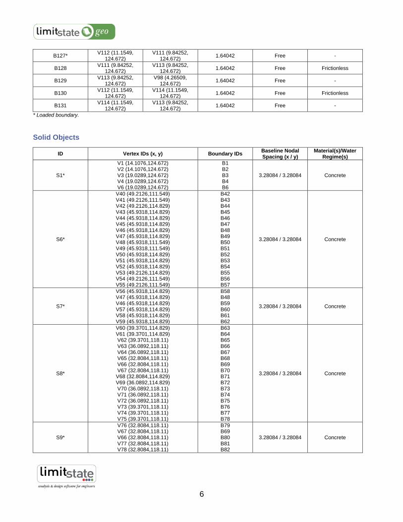
6
B127* V112 (11.1549,
124.672) V111 (9.84252,
124.672) 1.64042 Free -
B128 V111 (9.84252,
124.672) V113 (9.84252,
124.672) 1.64042 Free Frictionless
B129 V113 (9.84252,
124.672) V98 (4.26509,
124.672) 1.64042 Free -
B130 V112 (11.1549,
124.672) V114 (11.1549,
124.672) 1.64042 Free Frictionless
B131 V114 (11.1549,
124.672) V113 (9.84252,
124.672) 1.64042 Free -
* Loaded boundary.
Solid Objects
ID Vertex IDs (x, y) Boundary IDs Baseline Nodal Spacing (x / y)
Material(s)/Water Regime(s)
S1*
V1 (14.1076,124.672) V2 (14.1076,124.672) V3 (19.0289,124.672) V4 (19.0289,124.672) V6 (19.0289,124.672)
B1 B2 B3 B4 B6
3.28084 / 3.28084 Concrete
S6*
V40 (49.2126,111.549) V41 (49.2126,111.549) V42 (49.2126,114.829) V43 (45.9318,114.829) V44 (45.9318,114.829) V45 (45.9318,114.829) V46 (45.9318,114.829) V47 (45.9318,114.829) V48 (45.9318,111.549) V49 (45.9318,111.549) V50 (45.9318,114.829) V51 (45.9318,114.829) V52 (45.9318,114.829) V53 (49.2126,114.829) V54 (49.2126,111.549) V55 (49.2126,111.549)
B42 B43 B44 B45 B46 B47 B48 B49 B50 B51 B52 B53 B54 B55 B56 B57
3.28084 / 3.28084 Concrete
S7*
V56 (45.9318,114.829) V47 (45.9318,114.829) V46 (45.9318,114.829) V57 (45.9318,114.829) V58 (45.9318,114.829) V59 (45.9318,114.829)
B58 B48 B59 B60 B61 B62
3.28084 / 3.28084 Concrete
S8*
V60 (39.3701,114.829) V61 (39.3701,114.829) V62 (39.3701,118.11) V63 (36.0892,118.11) V64 (36.0892,118.11) V65 (32.8084,118.11) V66 (32.8084,118.11) V67 (32.8084,118.11)
V68 (32.8084,114.829) V69 (36.0892,114.829) V70 (36.0892,118.11) V71 (36.0892,118.11) V72 (36.0892,118.11) V73 (39.3701,118.11) V74 (39.3701,118.11) V75 (39.3701,118.11)
B63 B64 B65 B66 B67 B68 B69 B70 B71 B72 B73 B74 B75 B76 B77 B78
3.28084 / 3.28084 Concrete
S9*
V76 (32.8084,118.11) V67 (32.8084,118.11) V66 (32.8084,118.11) V77 (32.8084,118.11) V78 (32.8084,118.11)
B79 B69 B80 B81 B82
3.28084 / 3.28084 Concrete

7
V79 (32.8084,118.11) B83
S10*
V80 (26.9029,118.11) V81 (28.5433,118.11)
V82 (28.5433,121.391) V83 (23.9501,121.391) V84 (23.9501,121.391) V85 (23.622,121.391) V86 (23.622,121.391)
V110 (23.622,121.391) V87 (23.622,118.11) V88 (24.9344,118.11)
V89 (24.9344,121.391) V90 (23.9501,121.391) V91 (23.9501,121.391) V92 (27.8871,121.391) V93 (27.8871,121.391) V94 (26.9029,121.391)
B84 B85 B86 B87 B88 B89 B90 B125 B91 B92 B93 B94 B95 B96 B97 B98
3.28084 / 3.28084 Concrete
S13*
V105 (12.1391,124.672) V104 (14.1076,124.672) V2 (14.1076,124.672) V1 (14.1076,124.672)
V106 (13.7795,124.672) V107 (13.4514,124.672) V96 (12.1391,124.672) V95 (12.1391,124.672)
B114 B113 B1
B117 B118 B119 B99 B115
3.28084 / 3.28084 Concrete
S14*
V26 (59.0551,111.549) V27 (59.0551,111.549) V28 (55.7743,111.549) V29 (55.7743,111.549) V30 (59.0551,111.549) V31 (59.0551,111.549)
B28 B29 B30 B31 B32 B120
3.28084 / 3.28084 Concrete
S15*
V31 (59.0551,111.549) V32 (59.0551,108.268) V33 (59.0551,108.268) V34 (59.0551,108.268) V35 (59.0551,108.268) V36 (59.0551,111.549) V37 (62.336,111.549) V38 (62.336,108.268) V39 (62.336,108.268) V21 (62.336,108.268) V22 (62.336,108.268) V23 (62.336,111.549)
V24 (59.0551,111.549) V25 (59.0551,111.549) V26 (59.0551,111.549)
B33 B34 B35 B36 B37 B38 B39 B40 B41 B23 B24 B25 B26 B27 B120
3.28084 / 3.28084 Concrete
S17*
V110 (23.622,121.391) V86 (23.622,121.391)
V101 (23.294,121.391) V102 (22.6378,124.672) V108 (22.6378,121.391) V109 (23.294,121.391)
B90 B109 B110 B121 B122 B123
3.28084 / 3.28084 Concrete
S18*
V110 (23.622,121.391) V87 (23.622,118.11) V88 (24.9344,118.11)
V89 (24.9344,121.391) V90 (23.9501,121.391) V91 (23.9501,121.391) V92 (27.8871,121.391) V93 (27.8871,121.391) V94 (26.9029,121.391) V80 (26.9029,118.11) V81 (28.5433,118.11)
V82 (28.5433,121.391) V78 (32.8084,118.11)
B125 B91 B92 B93 B94 B95 B96 B97 B98 B84 B85 B108 B82
3.28084 / 3.28084 Silty Sand with Gravel

8
V79 (32.8084,118.11) V76 (32.8084,118.11) V67 (32.8084,118.11)
V68 (32.8084,114.829) V69 (36.0892,114.829) V70 (36.0892,118.11) V71 (36.0892,118.11) V72 (36.0892,118.11) V73 (39.3701,118.11) V74 (39.3701,118.11) V75 (39.3701,118.11)
V60 (39.3701,114.829) V61 (39.3701,114.829) V62 (39.3701,118.11)
V58 (45.9318,114.829) V59 (45.9318,114.829) V56 (45.9318,114.829) V47 (45.9318,114.829) V48 (45.9318,111.549) V49 (45.9318,111.549) V50 (45.9318,114.829) V51 (45.9318,114.829) V52 (45.9318,114.829) V53 (49.2126,114.829) V54 (49.2126,111.549) V55 (49.2126,111.549) V40 (49.2126,111.549) V41 (49.2126,111.549) V42 (49.2126,114.829) V28 (55.7743,111.549) V29 (55.7743,111.549) V30 (59.0551,111.549) V31 (59.0551,111.549) V32 (59.0551,108.268) V33 (59.0551,108.268) V34 (59.0551,108.268) V35 (59.0551,108.268) V36 (59.0551,111.549) V37 (62.336,111.549) V38 (62.336,108.268) V39 (62.336,108.268) V21 (62.336,108.268) V22 (62.336,108.268) V23 (62.336,111.549)
V12 (65.6168,108.268) V15 (85.3018,108.268) V100 (85.3018,98.4252) V99 (4.26509,98.4252) V98 (4.26509,124.672) V113 (9.84252,124.672) V114 (11.1549,124.672) V95 (12.1391,124.672) V105 (12.1391,124.672) V104 (14.1076,124.672) V2 (14.1076,124.672) V3 (19.0289,124.672) V4 (19.0289,124.672)
V103 (20.0131,124.672) V102 (22.6378,124.672) V108 (22.6378,121.391) V109 (23.294,121.391)
B83 B79 B70 B71 B72 B73 B74 B75 B76 B77 B78 B63 B64 B107 B61 B62 B58 B49 B50 B51 B52 B53 B54 B55 B56 B57 B42 B43 B106 B30 B31 B32 B33 B34 B35 B36 B37 B38 B39 B40 B41 B23 B24 B105 B15 B104 B103 B116 B129 B131 B102 B115 B114 B113 B2 B3
B112 B111 B121 B122 B123
S112*
V111 (9.84252,124.672) V97 (4.26509,124.672) V98 (4.26509,124.672) V113 (9.84252,124.672)
B126 B101 B129 B128
3.28084 / 3.28084 Concrete
S114* V114 (11.1549,124.672) B102 3.28084 / 3.28084 Concrete
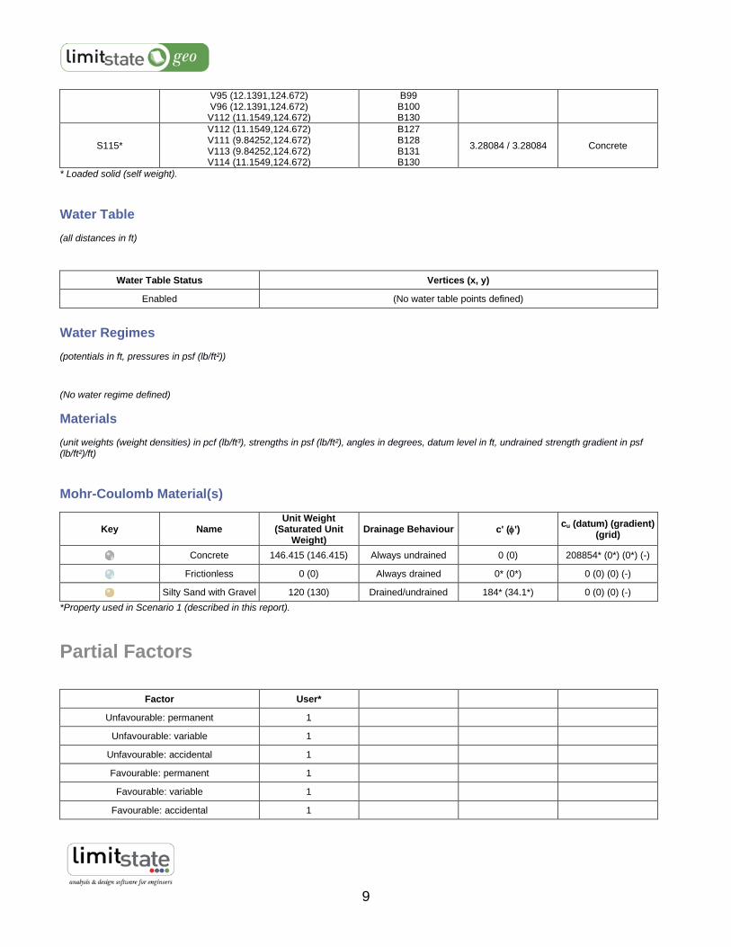
9
V95 (12.1391,124.672) V96 (12.1391,124.672) V112 (11.1549,124.672)
B99 B100 B130
S115*
V112 (11.1549,124.672) V111 (9.84252,124.672) V113 (9.84252,124.672) V114 (11.1549,124.672)
B127 B128 B131 B130
3.28084 / 3.28084 Concrete
* Loaded solid (self weight).
Water Table
(all distances in ft)
Water Table Status Vertices (x, y)
Enabled (No water table points defined)
Water Regimes
(potentials in ft, pressures in psf (lb/ft²))
(No water regime defined)
Materials
(unit weights (weight densities) in pcf (lb/ft³), strengths in psf (lb/ft²), angles in degrees, datum level in ft, undrained strength gradient in psf (lb/ft²)/ft)
Mohr-Coulomb Material(s)
Key Name Unit Weight
(Saturated Unit Weight)
Drainage Behaviour c' (') cu (datum) (gradient)
(grid)
Concrete 146.415 (146.415) Always undrained 0 (0) 208854* (0*) (0*) (-)
Frictionless 0 (0) Always drained 0* (0*) 0 (0) (0) (-)
Silty Sand with Gravel 120 (130) Drained/undrained 184* (34.1*) 0 (0) (0) (-)
*Property used in Scenario 1 (described in this report).
Partial Factors
Factor User*
Unfavourable: permanent 1
Unfavourable: variable 1
Unfavourable: accidental 1
Favourable: permanent 1
Favourable: variable 1
Favourable: accidental 1

10
c' 1
tan' 1
cu 1
*These partial factors were used in Scenario 1 (described in this report).
Loads
(normal and shear loads in psf (lb/ft²))
Boundary Objects
Loaded Object Type Loading Type Adequacy? Normal Shear
B6 Permanent Load neutral false 499.999 0
B25 Permanent Load neutral false 499.999 0
B44 Permanent Load neutral false 499.999 0
B65 Permanent Load neutral false 499.999 0
B86 Permanent Load neutral false 499.999 0
B127 Variable Load neutral true 2000 0
Solid Objects
Loaded Object Type Loading Type Adequacy?
S1 Permanent (unfactored self weight: 146.415 pcf (lb/ft³)) neutral true
S6 Permanent (unfactored self weight: 146.415 pcf (lb/ft³)) neutral true
S7 Permanent (unfactored self weight: 146.415 pcf (lb/ft³)) neutral true
S8 Permanent (unfactored self weight: 146.415 pcf (lb/ft³)) neutral true
S9 Permanent (unfactored self weight: 146.415 pcf (lb/ft³)) neutral true
S10 Permanent (unfactored self weight: 146.415 pcf (lb/ft³)) neutral true
S13 Permanent (unfactored self weight: 146.415 pcf (lb/ft³)) neutral true
S14 Permanent (unfactored self weight: 146.415 pcf (lb/ft³)) neutral true
S15 Permanent (unfactored self weight: 146.415 pcf (lb/ft³)) neutral true
S17 Permanent (unfactored self weight: 146.415 pcf (lb/ft³)) neutral true
S18 Permanent (unfactored self weight: 120 pcf (lb/ft³)) neutral true
S112 Permanent (unfactored self weight: 146.415 pcf (lb/ft³)) neutral true
S114 Permanent (unfactored self weight: 146.415 pcf (lb/ft³)) neutral true
S115 Permanent (unfactored self weight: 146.415 pcf (lb/ft³)) neutral true
Related Documents