Appl Intell (2010) 32: 193–204 DOI 10.1007/s10489-010-0214-7 Genetic algorithm for test pattern generator design Automatic evolution of circuits Tomasz Garbolino · Gregor Papa Published online: 23 February 2010 © Springer Science+Business Media, LLC 2010 Abstract The paper describes an approach for the gener- ation of a deterministic test pattern generator logic, which is composed of D-type and T-type flip-flops. This approach employs a genetic algorithm that searches for an acceptable practical solution in a large space of possible implementa- tions. In contrast to conventional approaches the proposed one reduces the gate count of a built-in self-test structure by concurrent optimization of multiple parameters that influ- ence the final solution. The optimization includes the search for: the optimal combination of register cells type; the pres- ence of inverters at inputs and outputs; the test patterns or- der in the generated test sequence; and the bit order of test patterns. Results of benchmark experiments and compari- son with similar studies demonstrate the efficiency of the proposed evolutionary approach. Keywords Optimization · Genetic algorithm · Design · Test pattern generator 1 Introduction Due to the growing complexity of modern integrated cir- cuits and increasing testing demands, boundary-scan ap- proach has been developed and is widely adopted in practice [28, 36]. A limited number of input/output pins represents T. Garbolino Institute of Electronics, Silesian University of Technology, 44100 Gliwice, Poland e-mail: [email protected] G. Papa ( ) Computer Systems Department, Jožef Stefan Institute, 1000 Ljubljana, Slovenia e-mail: [email protected] a bottleneck for testing of complex embedded cores where transfers of large amounts of test patterns and test results between the automatic test equipment (ATE) and the unit- under-test (UUT) are required. One alternative solution is to implement a built-in self-test (BIST) [21] of the UUT with on-chip test pattern generation (TPG) and on-chip output re- sponse analysis logic. In this way, communication with ex- ternal ATE is reduced to test initiation and transfer of test re- sults. One disadvantage of BIST implementation is the area overhead, which leads to longer signal routing paths. Mini- mization of the BIST logic is needed to decrease this draw- back. In the past, different TPG approaches have been pro- posed. They can be classified as ROM-based deterministic, algorithmic, exhaustive and pseudo-random. In the first ap- proach, deterministic patterns are stored in a ROM and a counter is used for their addressing, [12]. This approach is limited to small test pattern sets. Algorithmic TPG is mostly used for testing regular structures such as RAMs [23]. Ex- haustive TPG is a counter-based approach that is not able to generate specific sequence of test vectors. With some modi- fications, counter-based solutions are able to generate deter- ministic test patterns, [6]. Pseudo-random TPG is the most commonly applied technique in practice; here Linear Feed- back Shift Register (LFSR) or Cellular Automata (CA) are employed to generate pseudo-random test patterns. In order to decrease the complexity of a TPG designers usually try to embed deterministic test patterns into the vector sequence generated by some linear register. Such embedding can be done either by re-seeding a TPG or modifying its feedback function [27]. Some solutions also modify or transform the vector sequence produced by a LFSR in such a way that it contains deterministic test patterns [4, 16, 25, 39]. Different TPG solutions may be also classified in respect of the way the test patterns are delivered to the UUT. In

Welcome message from author
This document is posted to help you gain knowledge. Please leave a comment to let me know what you think about it! Share it to your friends and learn new things together.
Transcript

Appl Intell (2010) 32: 193–204DOI 10.1007/s10489-010-0214-7
Genetic algorithm for test pattern generator design
Automatic evolution of circuits
Tomasz Garbolino · Gregor Papa
Published online: 23 February 2010© Springer Science+Business Media, LLC 2010
Abstract The paper describes an approach for the gener-ation of a deterministic test pattern generator logic, whichis composed of D-type and T-type flip-flops. This approachemploys a genetic algorithm that searches for an acceptablepractical solution in a large space of possible implementa-tions. In contrast to conventional approaches the proposedone reduces the gate count of a built-in self-test structure byconcurrent optimization of multiple parameters that influ-ence the final solution. The optimization includes the searchfor: the optimal combination of register cells type; the pres-ence of inverters at inputs and outputs; the test patterns or-der in the generated test sequence; and the bit order of testpatterns. Results of benchmark experiments and compari-son with similar studies demonstrate the efficiency of theproposed evolutionary approach.
Keywords Optimization · Genetic algorithm · Design ·Test pattern generator
1 Introduction
Due to the growing complexity of modern integrated cir-cuits and increasing testing demands, boundary-scan ap-proach has been developed and is widely adopted in practice[28, 36]. A limited number of input/output pins represents
T. GarbolinoInstitute of Electronics, Silesian University of Technology,44100 Gliwice, Polande-mail: [email protected]
G. Papa (�)Computer Systems Department, Jožef Stefan Institute,1000 Ljubljana, Sloveniae-mail: [email protected]
a bottleneck for testing of complex embedded cores wheretransfers of large amounts of test patterns and test resultsbetween the automatic test equipment (ATE) and the unit-under-test (UUT) are required. One alternative solution is toimplement a built-in self-test (BIST) [21] of the UUT withon-chip test pattern generation (TPG) and on-chip output re-sponse analysis logic. In this way, communication with ex-ternal ATE is reduced to test initiation and transfer of test re-sults. One disadvantage of BIST implementation is the areaoverhead, which leads to longer signal routing paths. Mini-mization of the BIST logic is needed to decrease this draw-back.
In the past, different TPG approaches have been pro-posed. They can be classified as ROM-based deterministic,algorithmic, exhaustive and pseudo-random. In the first ap-proach, deterministic patterns are stored in a ROM and acounter is used for their addressing, [12]. This approach islimited to small test pattern sets. Algorithmic TPG is mostlyused for testing regular structures such as RAMs [23]. Ex-haustive TPG is a counter-based approach that is not able togenerate specific sequence of test vectors. With some modi-fications, counter-based solutions are able to generate deter-ministic test patterns, [6]. Pseudo-random TPG is the mostcommonly applied technique in practice; here Linear Feed-back Shift Register (LFSR) or Cellular Automata (CA) areemployed to generate pseudo-random test patterns. In orderto decrease the complexity of a TPG designers usually try toembed deterministic test patterns into the vector sequencegenerated by some linear register. Such embedding can bedone either by re-seeding a TPG or modifying its feedbackfunction [27]. Some solutions also modify or transform thevector sequence produced by a LFSR in such a way that itcontains deterministic test patterns [4, 16, 25, 39].
Different TPG solutions may be also classified in respectof the way the test patterns are delivered to the UUT. In
194 T. Garbolino, G. Papa
the test-per-scan approach each test pattern first needs to beshifted in a scan path during several clock cycles before it isapplied to the inputs of the UUT [25, 39]. This usually leadsto long testing times. If a shorter test duration is required,the test-per-clock method has to be adopted [6, 16, 20], sothat each test pattern is produced and stimulates the UUTinputs in a single clock cycle.
Specific test applications, like some types of non-concur-rent on-line BIST [1], may require TPG structures that arecapable of generating the set of precomputed deterministictest patterns in the minimum number of clock cycles. In oneof the first approaches the set of predefined test vectors is, soto speak, encoded into an appropriately designed network ofthe OR gates [11]. In turn, the solution proposed in [4] usesa network of XOR gates to transform a sequence of consec-utive vectors produced by a LFSR into a sequence of deter-ministic test patterns. In [20] a Multi-Input Signature Reg-ister (MISR) is combined with a combinational logic whichmodifies its state diagram in such a way that the MISR gen-erates a sequence of expected deterministic test patterns. Aninteresting method of designing a deterministic TPG basedon non-uniform CA was proposed in [5]. Yet another solu-tion employs a group of small Finite State Machines (FSMs)to generate a relatively short vector sequence that containsall deterministic test patterns [38].
Mostly, the proposed LFSR structures are based on D-type flip-flops, while in recent years LFSR composed of D-type and T-type flip-flops or the one containing solely T-type flip-flops is gaining popularity due to its low area over-head and high operating speed [17, 19]. Some applicationsof such a type of LFSRs can be found in [18, 20, 33]. Inparticular, works [18] and [20] present some concepts of op-timizing the LFSR structure containing D-type and T-typeflip-flops for generating deterministic test pattern sets.
Several papers cover the use of evolutionary techniquesin the optimization of hardware [10, 24, 31, 41]. In [37]a software-based methodology that automatically generatestest programs is described. The methodology is based onan evolutionary algorithm able to generate test programsfor different microprocessor cores. In [9] an automatic ap-proach, based on genetic algorithm (GA), targeting proces-sor cores is described that computes a test program able toattain high fault coverage figures.
In the area of TPG generation, GA has been used for thederivation of test pattern sets for target UUTs [7], and foroptimization of test sequence for weighted pseudo-randomtest generation to achieve the best test efficiency [14]. Asregards the synthesis of the TPG logic for actual genera-tion of the derived test patterns, GA approach has also beenused for the solutions based on cellular automata [8]. A de-tailed summary and analysis of various test pattern genera-tion techniques based on GA is presented in [15].
The aim of this work is the usage of deterministic test pat-tern generation for an on-line BIST structure, where func-tional units and registers that are not used for the compu-tations of the target application during individual time slotsare organized into a structure that is continuously tested inparallel with normal system operation.
The paper presents an approach for generation of a deter-ministic TPG logic based on a Linear Feedback Shift Reg-ister (LFSR). The LFSR is composed of D-type and T-typeflip-flops. The use of a LFSR for a TPG eliminates the needof a ROM for storing the seeds since a LFSR itself jumpsfrom a state to the next required state (seed) by invertingthe logic value of some of the bits of its next state. The ap-proach for searching the proper LFSR employs a GA to findan acceptable practical solution in a large space of possibleLFSR implementations. The goal is to develop a TPG thatwould generate only the required test vectors; therefore weconcurrently optimize the TPG structure (type of flip-flops,presence of inverters), the order of patterns in test sequence,and the bit-order of a test pattern.
The rest of the paper is organized as follows: in Sect. 2we describe the TPG structure, and give an example of areaminimization through the modification of the TPG structureand its test vectors; in Sect. 3 we describe the GA and thework of its operators; in Sect. 4 we describe the optimizationprocess and evaluate it; and in Sect. 5 we draw the conclu-sions.
2 TPG structure
A TPG is initialized with a given deterministic seed and rununtil the desired fault coverage is achieved. A test applica-tion time using a LFSR is significantly larger than what isrequired for applying the test set generated using a deter-ministic TPG; a vector set generated by a LFSR includes notonly useful vectors but also many other vectors that do notcontribute to the fault coverage. In our approach, the goal isto develop a TPG that would generate only the required testvectors (i.e., without intermittent non-useful vectors).
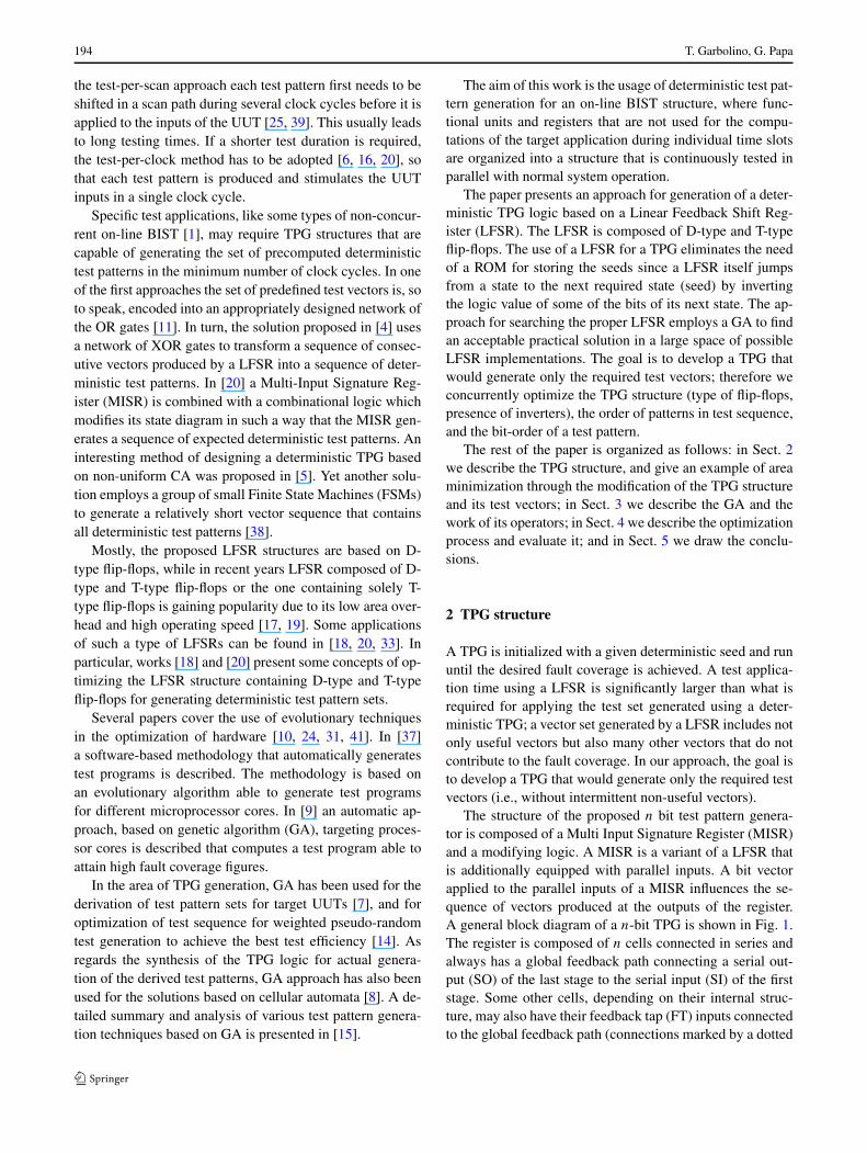
The structure of the proposed n bit test pattern genera-tor is composed of a Multi Input Signature Register (MISR)and a modifying logic. A MISR is a variant of a LFSR thatis additionally equipped with parallel inputs. A bit vectorapplied to the parallel inputs of a MISR influences the se-quence of vectors produced at the outputs of the register.A general block diagram of a n-bit TPG is shown in Fig. 1.The register is composed of n cells connected in series andalways has a global feedback path connecting a serial out-put (SO) of the last stage to the serial input (SI) of the firststage. Some other cells, depending on their internal struc-ture, may also have their feedback tap (FT) inputs connectedto the global feedback path (connections marked by a dotted
Genetic algorithm for test pattern generator design 195
Fig. 1 A block diagram of a n-bit TPG
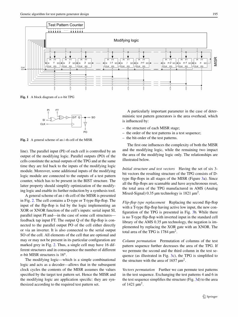
Fig. 2 A general scheme of an i-th cell of the MISR
line). The parallel input (PI) of each cell is controlled by anoutput of the modifying logic. Parallel outputs (PO) of thecells constitute the actual outputs of the TPG and at the sametime they are fed back to the inputs of the modifying logicmodule. Moreover, some additional inputs of the modifyinglogic module are connected to the outputs of a test patterncounter, which has to be present in the BIST structure. Thelatter property should simplify optimization of the modify-ing logic and enable its further reduction by a synthesis tool.
A general scheme of an i-th cell of the MISR is presentedin Fig. 2. The cell contains a D-type or T-type flip-flop. Theinput of the flip-flop is fed by the logic implementing anXOR or XNOR function of the cell’s inputs: serial input SI,parallel input PI and—in the case of some cell structures—feedback tap input FT. The output Q of the flip-flop is con-nected to the parallel output PO of the cell either directlyor via an inverter. It is also connected to the serial outputSO of the cell. All elements of the cell that are optional andmay or may not be present in its particular configuration aremarked grey in Fig. 2. Thus, a single cell may have 16 dif-ferent structures and in consequence the number of differentn-bit MISR structures is 16n.
The modifying logic—which is a simple combinationallogic and acts as a decoder—allows that in the subsequentclock cycles the contents of the MISR assumes the valuesspecified by the target test pattern set. Hence the MISR andthe modifying logic are application specific: they are syn-thesized according to the required test pattern set.
A particularly important parameter in the case of deter-ministic test pattern generators is the area overhead, whichis influenced by:
– the structure of each MISR stage;– the order of the test patterns in a test sequence;– the bit-order of the test patterns.
The first one influences the complexity of both the MISRand the modifying logic, while the remaining two impactthe area of the modifying logic only. The relationships areillustrated below.
Initial structure and test vectors Having the set of six 3-bit vectors the resulting structure of the TPG consists of D-type flip-flops in all stages of the MISR (Figure 3a). Sinceall the flip-flops are scannable and have asynchronous reset,the total area of the TPG manufactured in AMS (AnalogMixed-Signal) 0.35 µm technology is 1821 µm2.
Flip-flop type replacement Replacing the second flip-flopwith a T-type flip-flop having active low input, the new con-figuration of the TPG is presented in Fig. 3b. While thereis no T-type flip-flop with inverted input in the standard celllibrary of the AMS 0.35 µm technology, the negation is im-plemented by replacing the XOR gate with an XNOR. Thetotal area of the TPG is 1784 µm2.
Column permutation Permutation of columns of the testpattern sequence further decreases the area of the TPG. Ifwe permute the second and the third column in the test se-quence (as illustrated in Fig. 3c), the TPG is simplified tothe structure with the area of 1657 µm2.
Vectors permutation Further we can permute test patternsin the test sequence. Exchanging the test patterns 4 and 6 inthe test sequence simplifies the structure (Fig. 3d) to the areaof 1421 µm2.

196 T. Garbolino, G. Papa
Fig. 3 TPG structure: (a) initial structure, (b) replaced flip-flop type,(c) permutated columns, and (d) permutated vectors
A change of the MISR structure, the order of the test pat-terns in a test sequence and the bit-order of the test patternsmay result in a substantial area reduction of the TPG. Thesolution space is very broad: for an n-bit TPG producingthe sequence of m test patterns there are 16nm!n! possiblesolutions; therefore, an effective optimization procedure isrequired to find an acceptable practical solution.
3 Genetic algorithm
We implemented a genetic algorithm (GA) [2, 22]—one ofthe population-based evolutionary approaches—to optimizethe TPG structure. It was implemented due to algorithm’s in-trinsic parallelism that allows searching within a broad data-base of solutions in a search space simultaneously. The riskof converging to a local optimum exists, but efficient resultsof various research on different optimization problems [29,30, 34, 35, 40, 42] encouraged us to consider GA approachas a promising alternative in TPG synthesis optimization.
Our GA implementation (schematically presented inFig. 4) involves optimization of multiple design aspects(type of flip-flops, presence of inverters, order of patternsin a test sequence, and bit-order of a test pattern). We devel-oped our own version of the GA, to fully adapt to the specific
problem. The details of this GA, which takes into considera-tion the directions presented in [3, 32], are described below.
3.1 TPG encoding
The structure of the TPG, the order of test patterns, and theirbit order are encoded with three different chromosomes.These three chromosomes do not interact with each other,but are used to simultaneously optimize the structure of theTPG, the order of the test patterns, and the bit order of thetest patterns. They have to be optimized concurrently sincethey interact in complex ways, and their influence on finalsolution is interdependent.
The first chromosome, which encodes the structure of an-bit TPG, looks like
C1 = i11i12i13i14 · · · in1in2in3in4, (1)
where ijx represents a binary value; j (j = 1,2, . . . , n) de-termines each MISR stage and x determines the propertiesof a stage.(x = 1(f lip − f lop type),
2(inverted input),
3(f eedback input),
4(inverted output))
Here the value of position 1 can be 0 for D-type flip-flop or1 for T-type flip-flop; the value of position 2 can be 0 if noinverter is present at the input or 1 if inverter is present at theinput; the value of position 3 can be 0 if there is no feedbackat the input or 1 if there is a feedback at the input; the valueof position 4 can be 0 if no inverter is present at the outputor 1 if inverter is present at the output.
The second and the third chromosome, which encode theorder of the test patterns, and the bit order of test patterns,look like
C2 = a1a2 · · ·am, (2)
where m is the number of test vectors and aj (j = 1,2, . . . ,
m) is the label number of the test vector from the initial vec-tor list, and
C3 = b1b2 · · ·bn, (3)
where n is the number of flip-flops in the structure and bj
(j = 1,2, . . . , n) is the label number of the bit order of theinitial test patterns.
3.2 Population initialization
The initial population consists of N chromosomes, of eachtype.
Depending on requirements and input settings, the initialchromosome of the configuration can be set as (1) random

Genetic algorithm for test pattern generator design 197
Fig. 4 GA within the wholedesign process
values on all positions, (2) with values 0 on all positions,(3) with values 1 on all positions, (4) based on some inputconfiguration. In case of last three possibilities the valuesare permutated with some noise size np to avoid identicalchromosomes.
The initial chromosomes for orders are set as (1) ran-dom distribution of order values or (2) consecutive order ofnumbers. In the latter case some chromosomes are permu-tated to ensure versatile chromosomes. Since the numbersin these chromosomes represent the order of patterns or bitsin patterns their values can not be duplicated and no numbercan be missed; therefore both conditions must be consideredduring the initialization.
3.3 Genetic operators
The elitism prevents losing the best found solution by mem-orizing it. The substitution of the least-fit chromosomes withthe equal number of the best-ranked chromosomes ensuresbetter solutions to have more influence on the new genera-tion (steady-state implementation of selection). The ratio ofall chromosomes in the population to be replaced is set bythe ratio r .
With a two-point crossover scheme, chromosome matesare chosen randomly and with a probability pc all values be-tween two randomly chosen positions are swapped, whichleads to two new solutions that replace their original solu-tions. Figure 5(top) shows the example of crossover withcrossover points on positions 3 and 12.
The crossover in the case of test patterns order and bit-order of the test patterns is performed with the interchangeof positions that store the ordered numbers within the range(order-based crossover); for example within the range [2, 4],see Fig. 5(bottom).
In the mutation process each value of the chromosomemutates with a probability pm. However, since a high mu-tation rate resulted in a random walk through GA search
Fig. 5 Crossover: TPG configuration (top), pattern and bit orders (bot-tom)
Fig. 6 Mutation: TPG configuration (top), pattern and bit orders (bot-tom)
space, pm has to be chosen to be somewhat low. Two dif-ferent types of mutation are applied - bit inversion for thefirst chromosome and position-based mutation for the othertwo chromosomes (see Fig. 6 for details):
– configuration change, where a TPG configuration ischanged;
– position change, where pattern order and bit order arechanged.
The variable mutation probability pm is decreasing lin-early with each new population. Since each new populationgenerally fits better than the previous one, we overcome apossible disruptive effect of mutation at the late stages of theoptimization, and speed up the convergence of the GA to theoptimal solution in the final optimization stages. Moreover,the lower number of mutated positions in the later stagespresents some kind of a local search with minor movementsaround current solution, i.e. fine-tuning.

198 T. Garbolino, G. Papa
3.4 Fitness evaluation
After the recombination operators modify the solutions, thewhole new population is ready to be evaluated. Here the ex-ternal evaluation tool is used to evaluate each new chromo-some created by the GA, and a TPG cost approximation isobtained for each solution. In fact, an obtained cost approx-imation does not exactly represent an area overhead of thegiven solution. It rather reflects in quantitative form someset of properties of a TPG that make its structure either moreor less susceptible for effective area reduction during actualsynthesis process.
Evaluation tool On the basis of the equations for the reg-ister’s next-state, values of the outputs of the modifyinglogic for each vector but last in the test sequence can bederived. In [20] an Espresso [13] boolean optimization soft-ware was used for approximate cost estimation of the mod-ifying logic. On the one hand, the cost approximation pro-vided by the Espresso software was quite accurate in themajority of cases. On the other hand, its use led to long com-putation times of the GA that limited the applicability of thewhole tool to small and medium size circuits only. More-over, the approach proposed in [20] was in fact focused onreducing an area of the modifying logic only. In fact, it didnot consider the complexity of a MISR at all.
In this work, taking into account their previous experi-ences, the authors developed a new function fc for cost eval-uation of the TPG. The detailed formula of the function isprovided below:
fc(TPGi ) = CMISR
xi
X+ CMF
bi
B
1 − li
n
1 − ei
n, (4)
where
– n is the width of test patterns, the number of stages ofthe TPG, the maximum number of outputs of the moduleimplementing the modification function;
– m is the number of patterns in a test sequence;– i is the index of the given individual in the population, i.e.
the index for the TPG structure and its parameters;– TPGi is the structure of the TPG corresponding to the i-th
individual in the population;– CMF and CMISR are the coefficients that enable a user
to control whether to put more stress on minimizing thecomplexity of modifying logic or a MISR, respectively;
– xi is the number of XOR gates required to implement theMISR for the TPGi structure;
– X is the maximum number of XOR gates that may beused to built up the n-bit MISR composed of D- and T-type flip-flops (X = 3n − 1 in the case where there is aT-type flip-flop, feedback tap and parallel input in everystage of the MISR);
– bi is the total number of bit flips at the outputs of the mod-ule implementing the modification function for the TPGi
structure, produced during the generation of deterministictest patterns in consecutive m clock cycles;
– B is the maximum possible number of bit flips at the out-puts of the module implementing the modification func-tion during m consecutive clock cycles (B = n(m − 2));
– li is the number of the outputs of the module implement-ing the modification function for the TPGi structure thatkeep constant value during generating deterministic testpatterns in consecutive m clock cycles;
– ei is the total number of MISR inputs that can be fed fromthe same output of the module implementing the modifi-cation function for the TPGi structure.
The cost evaluation function aims at reducing the size ofthe modifying logic module by minimizing the number ofbit flips bi at the outputs of the module. In addition, it favorssuch structures of the TPG in which some number (li ) of par-allel inputs of the MISR can be driven by a constant value orwhere several (ei ) parallel inputs of the MISR can be drivenby the same output of the modifying logic module. At thesame time the function promotes the less complex structuresof the MISR by reducing the number xi of XOR gates thatare necessary to construct the register. Through appropri-ately setting the values of CMF and CMISR coefficients, theuser may decide whether the function will put more stress onminimizing the complexity of modifying logic or a MISR.
Note that the functionality of the inverter at the input ofthe flip-flop can be implemented by substituting the XORgate with the XNOR one, or vice versa. Similarly, insteadof adding the NOT gate at the Q output of the flip-flop, thecomplemented output Q can be used. Therefore, an employ-ment of the inverted inputs or outputs of the MISR does notinfluence the cost of the register and that is why the numberof inverters has not been involved in the TPG cost evaluationfunction fc .
It turned out that the TPG structures with lower valueof the cost evaluation function tend to have lower area over-head than those with higher value of the function. Moreover,although the function delivers less accurate cost approxima-tion than Espresso software, it is much faster and it tries toreduce the area overhead of the whole TPG instead of mod-ifying logic only.
3.5 Termination
After a certain number of populations is generated and eval-uated, the system is assumed to be in a non-converging state.The solution with the lowest area overhead is chosen as a fi-nal result.
Genetic algorithm for test pattern generator design 199
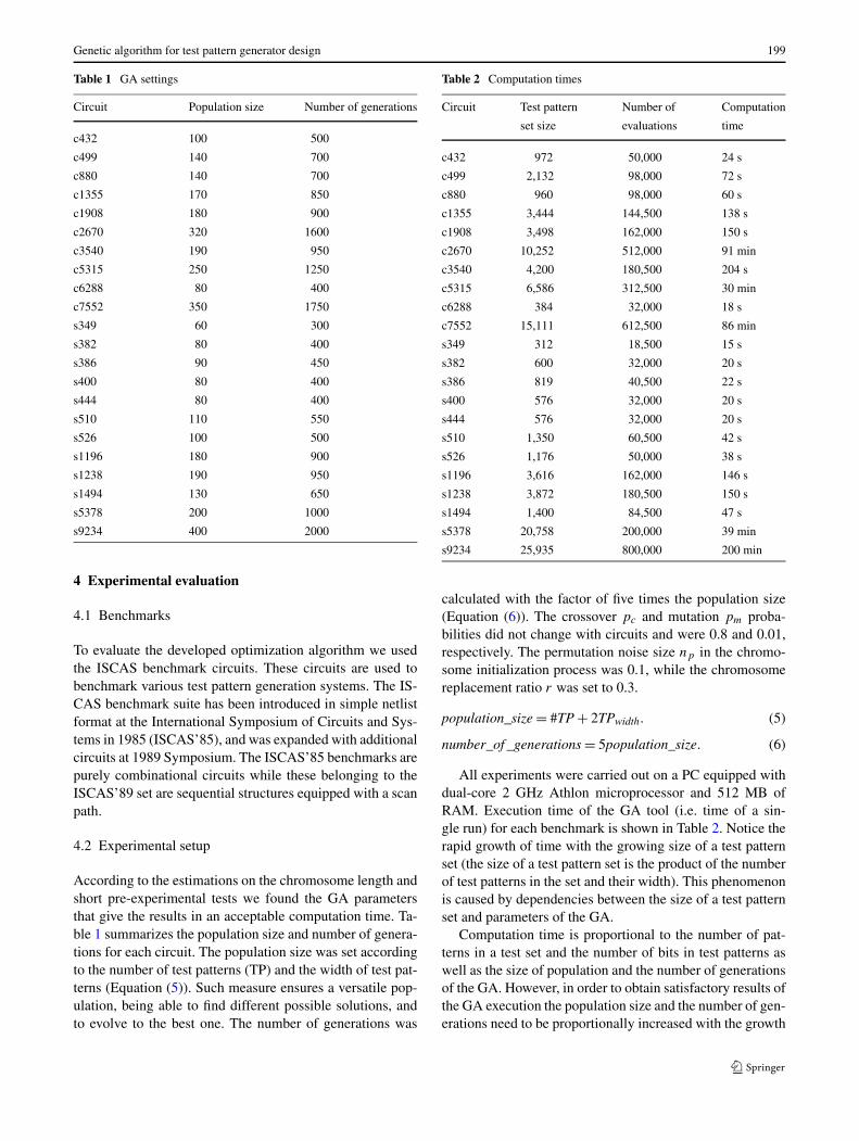
Table 1 GA settings
Circuit Population size Number of generations
c432 100 500
c499 140 700
c880 140 700
c1355 170 850
c1908 180 900
c2670 320 1600
c3540 190 950
c5315 250 1250
c6288 80 400
c7552 350 1750
s349 60 300
s382 80 400
s386 90 450
s400 80 400
s444 80 400
s510 110 550
s526 100 500
s1196 180 900
s1238 190 950
s1494 130 650
s5378 200 1000
s9234 400 2000
4 Experimental evaluation
4.1 Benchmarks
To evaluate the developed optimization algorithm we usedthe ISCAS benchmark circuits. These circuits are used tobenchmark various test pattern generation systems. The IS-CAS benchmark suite has been introduced in simple netlistformat at the International Symposium of Circuits and Sys-tems in 1985 (ISCAS’85), and was expanded with additionalcircuits at 1989 Symposium. The ISCAS’85 benchmarks arepurely combinational circuits while these belonging to theISCAS’89 set are sequential structures equipped with a scanpath.
4.2 Experimental setup
According to the estimations on the chromosome length andshort pre-experimental tests we found the GA parametersthat give the results in an acceptable computation time. Ta-ble 1 summarizes the population size and number of genera-tions for each circuit. The population size was set accordingto the number of test patterns (TP) and the width of test pat-terns (Equation (5)). Such measure ensures a versatile pop-ulation, being able to find different possible solutions, andto evolve to the best one. The number of generations was
Table 2 Computation times
Circuit Test pattern Number of Computation
set size evaluations time
c432 972 50,000 24 s
c499 2,132 98,000 72 s
c880 960 98,000 60 s
c1355 3,444 144,500 138 s
c1908 3,498 162,000 150 s
c2670 10,252 512,000 91 min
c3540 4,200 180,500 204 s
c5315 6,586 312,500 30 min
c6288 384 32,000 18 s
c7552 15,111 612,500 86 min
s349 312 18,500 15 s
s382 600 32,000 20 s
s386 819 40,500 22 s
s400 576 32,000 20 s
s444 576 32,000 20 s
s510 1,350 60,500 42 s
s526 1,176 50,000 38 s
s1196 3,616 162,000 146 s
s1238 3,872 180,500 150 s
s1494 1,400 84,500 47 s
s5378 20,758 200,000 39 min
s9234 25,935 800,000 200 min
calculated with the factor of five times the population size(Equation (6)). The crossover pc and mutation pm proba-bilities did not change with circuits and were 0.8 and 0.01,respectively. The permutation noise size np in the chromo-some initialization process was 0.1, while the chromosomereplacement ratio r was set to 0.3.
population_size = #TP + 2TPwidth. (5)
number_of _generations = 5population_size. (6)
All experiments were carried out on a PC equipped withdual-core 2 GHz Athlon microprocessor and 512 MB ofRAM. Execution time of the GA tool (i.e. time of a sin-gle run) for each benchmark is shown in Table 2. Notice therapid growth of time with the growing size of a test patternset (the size of a test pattern set is the product of the numberof test patterns in the set and their width). This phenomenonis caused by dependencies between the size of a test patternset and parameters of the GA.
Computation time is proportional to the number of pat-terns in a test set and the number of bits in test patterns aswell as the size of population and the number of generationsof the GA. However, in order to obtain satisfactory results ofthe GA execution the population size and the number of gen-erations need to be proportionally increased with the growth
200 T. Garbolino, G. Papa
of the size of a test pattern set. Thus, the size of a test patternset influences computation time both directly and indirectlythrough the parameters of the GA.
On the other hand, since the TPG design is off-line andone-time optimization process, optimization effectiveness isconsidered more important than reducing the computationtime. Therefore execution times that are less than one dayare still acceptable. Execution times of Leonardo Spectrumsynthesis software, used to calculate the area of the finalstructure, were less than 10 minutes for all benchmarks.
4.3 Results
The initial TPG structure is set according to the desired se-quence of test patterns. Then the GA tries to make new con-figuration while checking the allowed TPG structure and us-ing the external evaluation tool. The evaluation tool calcu-lates the cost of a given structure. After a number of itera-tions the best structure is chosen and implemented.
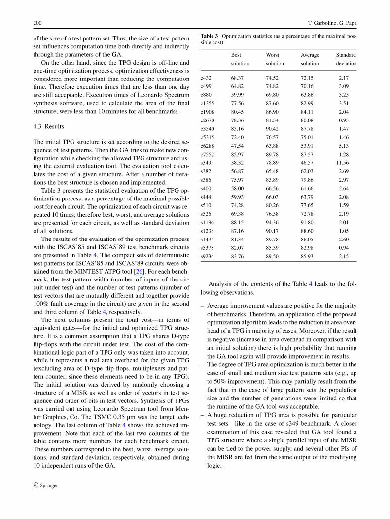
Table 3 presents the statistical evaluation of the TPG op-timization process, as a percentage of the maximal possiblecost for each circuit. The optimization of each circuit was re-peated 10 times; therefore best, worst, and average solutionsare presented for each circuit, as well as standard deviationof all solutions.
The results of the evaluation of the optimization processwith the ISCAS’85 and ISCAS’89 test benchmark circuitsare presented in Table 4. The compact sets of deterministictest patterns for ISCAS’85 and ISCAS’89 circuits were ob-tained from the MINTEST ATPG tool [26]. For each bench-mark, the test pattern width (number of inputs of the cir-cuit under test) and the number of test patterns (number oftest vectors that are mutually different and together provide100% fault coverage in the circuit) are given in the secondand third column of Table 4, respectively.
The next columns present the total cost—in terms ofequivalent gates—for the initial and optimized TPG struc-ture. It is a common assumption that a TPG shares D-typeflip-flops with the circuit under test. The cost of the com-binational logic part of a TPG only was taken into account,while it represents a real area overhead for the given TPG(excluding area of D-type flip-flops, multiplexers and pat-tern counter, since these elements need to be in any TPG).The initial solution was derived by randomly choosing astructure of a MISR as well as order of vectors in test se-quence and order of bits in test vectors. Synthesis of TPGswas carried out using Leonardo Spectrum tool from Men-tor Graphics, Co. The TSMC 0.35 µm was the target tech-nology. The last column of Table 4 shows the achieved im-provement. Note that each of the last two columns of thetable contains more numbers for each benchmark circuit.These numbers correspond to the best, worst, average solu-tions, and standard deviation, respectively, obtained during10 independent runs of the GA.
Table 3 Optimization statistics (as a percentage of the maximal pos-sible cost)
Best Worst Average Standard
solution solution solution deviation
c432 68.37 74.52 72.15 2.17
c499 64.82 74.82 70.16 3.09
c880 59.99 69.80 63.86 3.25
c1355 77.56 87.60 82.99 3.51
c1908 80.45 86.90 84.11 2.04
c2670 78.36 81.54 80.08 0.93
c3540 85.16 90.42 87.78 1.47
c5315 72.40 76.57 75.01 1.46
c6288 47.54 63.88 53.91 5.13
c7552 85.97 89.78 87.57 1.28
s349 38.32 78.89 46.57 11.56
s382 56.87 65.48 62.03 2.69
s386 75.97 83.89 79.86 2.97
s400 58.00 66.56 61.66 2.64
s444 59.93 66.03 63.79 2.08
s510 74.28 80.26 77.65 1.59
s526 69.38 76.58 72.78 2.19
s1196 88.15 94.36 91.80 2.01
s1238 87.16 90.17 88.60 1.05
s1494 81.34 89.78 86.05 2.60
s5378 82.07 85.39 82.98 0.94
s9234 83.76 89.50 85.93 2.15
Analysis of the contents of the Table 4 leads to the fol-lowing observations.
– Average improvement values are positive for the majorityof benchmarks. Therefore, an application of the proposedoptimization algorithm leads to the reduction in area over-head of a TPG in majority of cases. Moreover, if the resultis negative (increase in area overhead in comparison withan initial solution) there is high probability that runningthe GA tool again will provide improvement in results.
– The degree of TPG area optimization is much better in thecase of small and medium size test patterns sets (e.g., upto 50% improvement). This may partially result from thefact that in the case of large pattern sets the populationsize and the number of generations were limited so thatthe runtime of the GA tool was acceptable.
– A huge reduction of TPG area is possible for particulartest sets—like in the case of s349 benchmark. A closerexamination of this case revealed that GA tool found aTPG structure where a single parallel input of the MISRcan be tied to the power supply, and several other PIs ofthe MISR are fed from the same output of the modifyinglogic.

Genetic algorithm for test pattern generator design 201
Table 4 Results of TPG area
Circuit Test Number Initial Optimized TPG Improvement in %
pattern of test TPG best worst average st.dev. best worst average
width patterns
c432 36 27 375.2 329.3 358.9 347.5 10.4 12.2 4.3 7.4
c499 41 52 567.2 448.7 517.9 485.7 21.4 20.9 8.7 14.4
c880 60 16 390.0 345.6 402.2 367.9 18.7 11.4 −3.1 5.7
c1355 41 84 713.8 698.9 789.4 747.8 31.6 2.1 −10.6 −4.8
c1908 33 106 1226.1 1078.8 1165.2 1127.8 27.4 12.0 5.0 8.0
c2670 233 44 2647.5 2669.4 2777.5 2727.9 31.7 −0.8 −4.9 −3.0
c3540 50 84 1417.4 1353.8 1437.3 1395.5 23.4 4.5 −1.4 1.5
c5315 178 37 1911.0 1744.7 1845.2 1807.4 35.2 8.7 3.4 5.4
c6288 32 12 186.3 128.7 173.0 146.0 13.9 30.9 7.1 21.6
c7552 207 73 3888.6 3876.6 4048.6 3948.9 57.7 0.3 −4.1 −1.6
s349 24 13 163.3 85.2 175.3 103.5 25.7 47.9 −7.3 36.6
s382 24 25 252.8 180.3 207.6 196.6 8.5 28.7 17.9 22.2
s386 13 63 332.3 280.7 310.0 295.2 11.0 15.5 6.7 11.2
s400 24 24 258.5 173.6 199.3 184.6 7.9 32.8 22.9 28.6
s444 24 24 249.1 176.6 194.6 188.0 6.1 29.1 21.9 24.5
s510 25 54 521.2 438.1 473.3 458.0 9.4 16.0 9.2 12.1
s526 24 49 438.1 362.6 400.2 380.3 11.5 17.2 8.7 13.2
s1196 32 113 1269.4 1195.5 1279.7 1244.9 27.3 5.8 −0.8 1.9
s1238 32 121 1370.5 1271.0 1314.9 1292.0 15.3 7.3 4.1 5.7
s1494 14 100 531.6 487.3 537.9 515.5 15.6 8.3 −1.2 3.0
s5378 214 97 5280.7 4909.4 5107.7 4963.6 56.3 7.0 3.3 6.0
s9234 247 105 6455.9 5994.8 6405.6 6150.4 153.8 7.1 0.8 4.7
As mentioned before, the state of the art Espressoboolean minimizer was used for a TPG cost evaluation inthe previous edition of the GA-based TPG optimization tool.Experimental results obtained with the use of the tool for sixISCAS’85 benchmarks were reported in [20]. In order to re-duce execution times the Espresso was replaced by a newtime effective TPG cost approximation function in the cur-rent edition of the GA tool. Thus, it seems to be interestingand important to asses and compare the quality of resultsprovided by both versions of the tool as well as to comparethem with other state of the art solutions, e.g. those pre-sented in [4, 5]. However, a direct comparison of the resultsobtained by the authors with these presented in [4] and [5]is difficult since different sets of test patterns having differ-ent sizes were used for experiments in all works. In orderto make such comparison possible a new area measure wasproposed. It is defined by (7) and expresses the area over-head of the TPG per bit of the test pattern set.
area_per_bit = area
TPwidth × #TP. (7)
Results obtained by the current version of the GA tool aswell as these reported in [4], [5] and [20] have been gath-ered in Table 5. The first two columns of the table contain
the name of the benchmark circuit and the test pattern width,respectively. Next four columns include actual experimen-tal data for solutions presented in [4, 5, 20] and current ap-proach. For each solution the number of vectors in a test pat-tern set and the area of the combinational logic part of theTPG expressed in terms of the number of equivalent gatesper bit of the test pattern set (area_per_bit) are provided inthe first and the last sub-column, respectively. Moreover, inthe case of the TPG that was worked out in [5], the length ofthe test sequence (in clock cycles) is included in the middlesub-column. For remaining three TPG structures, the lengthof the test sequence is equal to the number of deterministictest patterns.
It is a common assumption that a TPG shares D-type flip-flops with the circuit under test. That is why the cost of thecombinational logic part of the TPG only was taken in toaccount in experimental results.
Since the results presented in [4] (Table 4, Scheme I)were obtained with the use of some made up sample ASIClibrary, they were recalculated as if the TPG structures de-signed in [4] were synthesized for the TSMC 0.35 µm li-brary. In [5] the costs of TPG structures are expressed interms of the number of equivalent D-type flip-flops. The cost

202 T. Garbolino, G. Papa
Table 5 A comparison of GA-based approach through area_per_bit in [4, 5] and [20]
Circuit Test [4] [5] [20] New approach
pattern Number Area Number Area Test Number Area Number Area
width of test of test sequence of test of test
patterns patterns length patterns patterns
c432 36 48 0.47 N/A N/A N/A 27 0.11 27 0.34
c499 41 52 0.47 79 0.23 18975 52 0.10 52 0.21
c880 60 49 0.44 N/A N/A N/A 16 0.29 16 0.36
c1355 41 85 0.44 118 0.25 113400 84 0.09 84 0.20
c1908 33 111 0.44 139 0.38 7597 106 0.32 106 0.31
c2670 233 100 0.36 87 0.17 3564 44 N/A 44 0.26
c3540 50 143 0.46 N/A N/A N/A 84 N/A 84 0.32
c5315 178 112 0.40 N/A N/A N/A 37 N/A 37 0.26
c6288 32 27 0.48 29 0.67 624 12 0.54 12 0.34
c7552 207 178 0.37 35 0.28 11058 73 N/A 73 0.26
(expressed in terms of equivalent gates) of the D-type flipflop having the smallest area in the TSMC 0.35 µm librarywas taken into account in order to translate these values intothe numbers of equivalent gates.
The results obtained with the use of the new GA-basedoptimization tool significantly outperform those reported in[4] for all benchmarks. They are also better than those pub-lished in [5] for all benchmark circuits except one (c2670),despite the fact that the FSM-based TPG presented in [5]requires much more clock cycles to produce all determin-istic test patterns than the solution proposed in this work.Moreover, in the case of two benchmark circuits the newGA based optimization tool was also able to produce a TPGstructure with smaller area overhead than the one obtainedin [20].
Closer examination of the experimental results led to thefollowing observations:
– The GA tool equipped with fast but simple cost approx-imation function gives better results for the test patternsets containing small number of test patterns. The widthof the patterns seems to be irrelevant.
– In the case of some benchmarks the new GA tool wasable to find a TPG structure in which some inputs of theMISR can be tied to a constant logic value and severalother inputs of the MISR can be driven by the same outputof the modifying logic. So, the proposed cost approxima-tion function is capable of detecting specific properties ofthe test pattern set resulting in significant reduction of theTPG area.
– In this work TPG structures produced by the GA toolwere directly synthesized by the Leonardo Spectrum soft-ware. In [20] each TPG structure produced by the GA toolwas first optimized by the state of the art boolean mini-mizer Espresso and then synthesized by Leonardo Spec-
trum software. Obviously, the fact that the boolean opti-mization step was omitted in the TPG design flow adoptedin the current work negatively influenced the quality ofachieved results. This has to be corrected in the future.
5 Conclusion
When a TPG fails to provide the desired fault coveragewithin the given test length, application specific determin-istic TPGs are employed. These are more complex thanpseudo random TPGs since they require additional logic toprevent the generation of non-useful test patterns. Area over-head is one of the important issues in the design of determin-istic TPGs.
This paper presents a deterministic TPG based on aMISR. A MISR is composed of D-type and T-type flip-flops, XOR and XNOR two-input gates and inverters. Thesearch for the optimal structure of the TPG is performedby a genetic algorithm. Following the conclusions from theprevious work [20], a new, fast but simple cost approxima-tion function was worked out. Instead of performing actualboolean optimization or synthesis of the TPG it only ex-amines some properties of the components of the TPG (itsMISR and modifying logic) that influence their area and ex-presses these properties in a numerical form. On the onehand, simplification of the cost approximation function neg-atively influenced accuracy of evaluations of the TPG areaoverhead. This in turn usually led to deterioration of ob-tained results. On the other hand, the use of the fast functionfor cost approximation significantly reduced the search timeof the genetic algorithm. In consequence, the proposed ap-proach became practically applicable even to large circuits.Moreover, the experimental results prove that despite the
Genetic algorithm for test pattern generator design 203
lowered accuracy of evaluation of the TPG area overhead,the GA tool is still capable of improving the initial structureof the TPG.
References
1. Aktouf C, Robach C, Kac U, Novak F (1999) On-line testing ofembedded architectures using idle computations and clock cycles.In: Proc. 5th IEEE international on-line testing workshop, Rhodes,Greece, pp 28–32
2. Bäck T (1996) Evolutionary algorithms in theory and practice. Ox-ford University Press, Oxford
3. Bäck T, Fogel DB, Michalewicz Z (2000) Evolutionary computa-tion 1: basic algorithms and operators. Taylor & Francis, London
4. Bellos M, Kagaris D, Nikolos D (2002) Test set embedding basedon phase shifters. In: Proceedings fourth European dependablecomputing conference, EDCC-4. Toulouse, France, pp 90–101
5. Cao B, Xiao L, Wang Y (2008) A low power deterministic testpattern generator for BIST based on cellular automata. In: Proc.4th IEEE international symposium on electronic design, test &applications, DELTA 2008, Hong Kong, China, pp 266–269
6. Chakrabarty K, Muray B, Iyengar V (2000) Deterministic built intest pattern generation for high performance circuits using twistedring counters. IEEE Trans Very Large Scale Integr (VLSI) Syst8:633–636
7. Corno F, Prinetto P, Rebaudengo M, Reorda MS (1996) Gatto: agenetic algorithm for automatic test pattern generation for largesynchronous sequential circuits. IEEE Trans Comput-Aided Des15:943–951
8. Corno F, Prinetto P, Reorda MS (1996) A genetic algorithm for au-tomatic generation of test logic for digital circuits. In: ProceedingsIEEE international conference on tools with artificial intelligence.Toulouse, France, pp 10–16
9. Corno F, Sonza Reorda M, Squillero G, Violante M (2000) A ge-netic algorithm-based system for generating test programs for mi-croprocessor IP cores. ictai, pp.0195, In: Proc. 12th IEEE interna-tional conference on tools with artificial intelligence (ICTAI’00),Vancouver, Canada, pp 195
10. Drechsler R, Drechsler N (2002) Evolutionary algorithms for em-bedded system design. Kluwer, Dordrecht
11. Dufaza C, Chevalier C, Lew Yan Voon LFC (1993) LFSROM -a hardware test pattern generator for deterministic ISCAS85 testsets. In Proc. 2nd IEEE Asian test symposium, Beijing, China, pp160–165
12. Edirisooriya G, Robinson J (1992) Design of low cost ROM basedtest generators. In: Proceedings IEEE VLSI test symposium, pp61–66
13. Espresso (1988) UC Berkeley. http://www-cad.eecs.berkeley.edu:80/software/software.html
14. Favalli M, Dalpasso M (2002) An evolutionary approach to the de-sign of on-chip pseudorandom test pattern generators. In: Proceed-ings of the 2002 design, automation and test in Europe, p 1122
15. Fin A, Fummi F (2003) Genetic algorithms: the philosopher’sstone or an effective solution for high-level TPG? In: EighthIEEE international high-level design validation and test workshop(HLDVT’03), pp 163–168
16. Fišer P (2007) Pseudo-random pattern generator design forcolumn-matching BIST. In: Proc. 10th Euromicro conference ondigital system design architectures, methods and tools, DSD 2007,Lubeck, Germany, pp 657–663
17. Garbolino T, Hlawiczka A (1999) A new LFSR with D and T flipflops as an effective test pattern generator for VLSI circuits. In:Lecture notes in computer science, vol 1667, pp 321–338
18. Garbolino T, Hlawiczka A (2002) Efficient test pattern generatorsbased on specific cellular automata structures. Microelectron Re-liab 42(6):975–983
19. Garbolino T, Hlawiczka A, Kristof A (2000) Fast and low areaTPG based on T type flip flops can be easily integrated to the scanpath. In: Proceedings IEEE European test workshop, Cascais, pp161–166
20. Garbolino T, Papa G (2008) Test pattern generator design opti-mization based on genetic algorithm. In: Proceedings 21st interna-tional conference on industrial, engineering and other applicationsof applied intelligent systems, IEA/AIE 2008, Wroclaw, Poland,pp 580–589
21. Garvie M, Thompson A (2003) Evolution of self-diagnosing hard-ware. In: Proc. 5th int. conf. on evolvable systems (ICES‘03). Lec-ture notes in computer science, vol. 2606, pp 238–248
22. Goldberg D (1989) Genetic algorithms in search, optimization,and machine learning. Addison-Wesley, Reading
23. van de Goor A (1991) Testing semiconductor memories: theoryand practice. Wiley, New York
24. Guo R, Li B, Zou Y, Zhuang Z (2007) Hybrid quantum probabilis-tic coding genetic algorithm for large scale hardware-software co-synthesis of embedded systems. In: Proc. IEEE congress on evo-lutionary computation, CEC 2007, Singapore, pp 3454-3458
25. Hakmi AW, Wunderlich HJ, Zoellin CG, Glowatz A, Hapke F,Schloeffel J, Souef L (2007) Programmable deterministic built-inself-test. In: Proc. IEEE international test conference, Santa Clara,California, USA, pp 1–9
26. Hamzaoglu I, Patel JH (1998) Test set compaction algorithms forcombinational circuits. In: Proceedings of the international con-ference on computer-aided design, San Jose, USA, pp 283–289
27. Hellebrand S, Rajski J, Tarnick S, Venkataraman S, Courtois B(1995) Built-in test for circuits with scan based on reseeding ofmultiple-polynomial linear feedback shift registers. IEEE TransComput 44:223–233
28. Khalil M, Robach C, Novak F (2002) Diagnosis strategies forhardware or software systems. J Electron Test, Theory Appl18:241–251
29. Korošec P, Šilc J (2008) Using stigmergy to solve numerical opti-mization problems. Comput Informatics 7(3):377–402
30. Koroušic-Seljak B (2002) Timetable construction using generalheuristic techniques. J Electr Eng 53(3–4):61–69
31. Mazumder P, Rudnick EM (1999) Genetic algorithms for VLSIdesign, layout & test automation. Prentice Hall, New York
32. Michalewicz Z, Fogel DB (2004) How to solve it: modern heuris-tics. Springer, Berlin
33. Novak O, Pliva Z, Nosek J, Hlawiczka A, Garbolino T, GucwaK (2004) Test-per-clock logic BIST with semi-deterministic testpatterns and zero-aliasing compactor. J Electron Test, Theory Appl20(1):109–122
34. Papa G, Koroušic-Seljak B (2005) An artificial intelligence ap-proach to the efficiency improvement of a universal motor. EngAppl Artif Intell 18(1):47–55
35. Papa G, Šilc J (2002) Automatic large-scale integrated circuit syn-thesis using allocation-based scheduling algorithm. MicroprocessMicrosyst 26(3):139–147
36. Parker K (2003) The boundary-scan handbook, 3rd edn. Kluwer,Dordrecht
37. Sanchez E, Squillero G (2007) Evolutionary techniques applied tohardware optimization problems: test and verification of advancedprocessors. Stud Comput Intell 66:303–326
38. Sudireddy S, Kakade J, Kagaris D (2008) Deterministic built-inTPG with segmented FSMs. In: Proc. 14th IEEE international on-line testing symposium, IOLTS 2008, Rhodes, Greece, pp 261–266
39. Touba N, McCluskey E (2001) Bit-fixing in pseudorandom se-quences for scan BIST. IEEE Trans Comput-Aided Des Integr Cir-cuits Syst 20:545–555
204 T. Garbolino, G. Papa
40. Tušar T, Korošec P, Papa G, Filipic B, Šilc J (2007) A comparativestudy of stochastic optimization methods in electric motor design.Appl Intell 27(2):101–111
41. Veiras Bolzani LM, Sanchez E, Schillaci M, Squillero G (2007)Co-evolution of test programs and stimuli vectors for testing ofembedded peripheral cores. In: Proc. IEEE congress on evolution-ary computation, CEC 2007, Singapore, pp 3474–3481
42. Wu CL, Chau KW (2006) A flood forecasting neural networkmodel with genetic algorithm. Int J Environ Pollut 28(3–4):261–273
Tomasz Garbolino is an assistantprofessor at the Faculty of Au-tomatic Control, Electronics andComputer Science, Silesian Uni-versity of Technology, Gliwice,Poland. He received his M.S. andPh.D. degrees (with honors) in Elec-tronics from the Technical Univer-sity of Gliwice in 1993 and 2002,respectively. His research interestsencompass built-in self-test struc-tures for digital circuits and SOCs,with particular focus on test patterngenerators and test pattern decom-pression techniques, as well as de-
sign for testability issues. He is a co-author of several papers that havebeen published in proceedings of international conferences and jour-nals.
Gregor Papa is a researcher atthe Computer Systems Department,Jožef Stefan Institute, Ljubljana,Slovenia. He is also an assistant pro-fessor at the Jožef Stefan Interna-tional Postgraduate School. He re-ceived his M.Sc. and Ph.D. degreesin Electrical Engineering from theUniversity of Ljubljana, Slovenia,in 2000 and 2002, respectively. Hisresearch interests include optimiza-tion techniques, metaheuristic algo-rithms, high-level synthesis of in-tegrated circuits, hardware imple-mentations of high-complexity al-
gorithms, and industrial product improvements. His work is publishedin several international journals, and conference proceedings.
Related Documents