SANDIA REPORT SAND2012-10406 Unlimited Release December 2012 Generic Small Modular Reactor Plant Design Tom G. Lewis, Benjamin B. Cipiti, Sabina E. Jordan, Gregory A. Baum Prepared by Sandia National Laboratories Albuquerque, New Mexico 87185 and Livermore, California 94550 Sandia National Laboratories is a multi-program laboratory managed and operated by Sandia Corporation, a wholly owned subsidiary of Lockheed Martin Corporation, for the U.S. Department of Energy's National Nuclear Security Administration under contract DE-AC04-94AL85000. Approved for public release; further dissemination unlimited.

Welcome message from author
This document is posted to help you gain knowledge. Please leave a comment to let me know what you think about it! Share it to your friends and learn new things together.
Transcript
SANDIA REPORT SAND2012-10406 Unlimited Release December 2012
Generic Small Modular Reactor Plant Design
Tom G. Lewis, Benjamin B. Cipiti, Sabina E. Jordan, Gregory A. Baum
Prepared by Sandia National Laboratories Albuquerque, New Mexico 87185 and Livermore, California 94550
Sandia National Laboratories is a multi-program laboratory managed and operated by Sandia Corporation, a wholly owned subsidiary of Lockheed Martin Corporation, for the U.S. Department of Energy's National Nuclear Security Administration under contract DE-AC04-94AL85000. Approved for public release; further dissemination unlimited.
2
Issued by Sandia National Laboratories, operated for the United States Department of Energy by
Sandia Corporation.
NOTICE: This report was prepared as an account of work sponsored by an agency of the United
States Government. Neither the United States Government, nor any agency thereof, nor any of their
employees, nor any of their contractors, subcontractors, or their employees, make any warranty,
express or implied, or assume any legal liability or responsibility for the accuracy, completeness, or
usefulness of any information, apparatus, product, or process disclosed, or represent that its use
would not infringe privately owned rights. Reference herein to any specific commercial product,
process, or service by trade name, trademark, manufacturer, or otherwise, does not necessarily
constitute or imply its endorsement, recommendation, or favoring by the United States
Government, any agency thereof, or any of their contractors or subcontractors. The views and
opinions expressed herein do not necessarily state or reflect those of the United States Government,
any agency thereof, or any of their contractors.
Printed in the United States of America. This report has been reproduced directly from the best
available copy.
Available to DOE and DOE contractors from
U.S. Department of Energy
Office of Scientific and Technical Information
P.O. Box 62
Oak Ridge, TN 37831
Telephone: (865) 576-8401
Facsimile: (865) 576-5728
E-Mail: [email protected]
Online ordering: http://www.osti.gov/bridge
Available to the public from
U.S. Department of Commerce
National Technical Information Service
5285 Port Royal Rd.
Springfield, VA 22161
Telephone: (800) 553-6847
Facsimile: (703) 605-6900
E-Mail: [email protected]
Online order: http://www.ntis.gov/help/ordermethods.asp?loc=7-4-0#online
3
SAND2012-10406
Unlimited Release
December 2012
Generic Small Modular Reactor Plant Design
Tom G. Lewis1, Benjamin B. Cipiti
2, Sabina E. Jordan
3, Gregory A. Baum
4
1Advanced Reactor Concepts,
2Advanced Nuclear Fuel Cycles,
3Policy and Decision Analytics,
4International Nuclear Security Engineering
Sandia National Laboratories
P.O. Box 5800
Albuquerque, New Mexico 87185-MS1136
Abstract
This report gives an overview of expected design characteristics, concepts, and
procedures for small modular reactors. The purpose of this report is to provide those
who are interested in reducing the cost and improving the safety of advanced nuclear
power plants with a generic design that possesses enough detail in a non-sensitive
manner to give merit to their conclusions. The report is focused on light water reactor
technology, but does add details on what could be different in a more advanced
design (see Appendix).
Numerous reactor and facility concepts were used for inspiration (documented in the
bibliography). The final design described here is conceptual and does not reflect any
proposed concept or sub-systems, thus any details given here are only relevant within
this report. This report does not include any design or engineering calculations.

4

5
CONTENTS
1. Overview .................................................................................................................................... 9 1.1. Major Buildings and Structures .................................................................................... 11
1.1.1. Reactor Building ............................................................................................. 12 1.1.2. Control Room Buildings ................................................................................. 16 1.1.3. Fuel Storage and Maintenance Building ......................................................... 18 1.1.4. Nuclear Receiving ........................................................................................... 20 1.1.5. Non-Nuclear Receiving .................................................................................. 21
1.1.6. Turbine Buildings and Transformers .............................................................. 21 1.1.6. Security Building ............................................................................................ 22 1.1.7 Central and Secondary Alarm Stations ............................................................... 23 1.1.8. Radioactive Waste Building ............................................................................... 23
1.2. Major Plant Components .............................................................................................. 24
1.2.1. Reactor System ................................................................................................... 24 1.2.2. Shielding Structure and Containment ................................................................. 24
1.2.3. Fuel Storage ........................................................................................................ 24 1.2.4. Refueling Equipment .......................................................................................... 25
1.3. Miscellaneous Balance of Plant and Supporting Systems Design ................................... 25 1.3.1 Cask Storage Pad ................................................................................................. 25 1.3.2. Cooling Towers/Dry Cooling Radiators ............................................................. 26
1.3.3. Switchyard .......................................................................................................... 26
2. Key Components of the Passive Core CooLing System ......................................................... 27
2.1 Core Makeup Tanks .......................................................................................................... 28 2.2. Outside Containment Pool ............................................................................................... 29 2.3. Ultimate Heat Sink ........................................................................................................... 29
2.4. Pressure Relief System .................................................................................................... 29
3. Other Safety Systems ................................................................................................................ 30 3.1 Decay Heat Removal System............................................................................................ 30 3.2 Instrument & Controls (I&C) and Safety Control & Instrumentation System (SCIS) ..... 30
3.3. AC Power ......................................................................................................................... 30 3.4. Reactivity Control System ............................................................................................... 31 3.5. Standby Liquid Control System ....................................................................................... 31
3.6. Core Thermal-Hydraulic Internals ................................................................................... 31 3.7. Safety Related HVAC ...................................................................................................... 32 3.8. Primary Containment Service Air System ....................................................................... 32 3.9. Fire Containment/Control System ................................................................................... 33 3.10. Communication Equipment ........................................................................................... 33
4. Operation Procedures ................................................................................................................ 34 4.1. Refueling .......................................................................................................................... 34
4.2. Fuel Shipments................................................................................................................. 35 4.3. Personnel Entry and Exit ................................................................................................. 36 4.4. Security Systems .............................................................................................................. 36
5. BIBLiOGRAPHY .................................................................................................................... 39
6. Appendix ................................................................................................................................... 41

6
FIGURES
Figure 1. Plant Layout.................................................................................................................. 10 Figure 2. Above Ground Reactor Building Floors....................................................................... 13 Figure 3. Reactor Building, Safety Divisions 1 & 2, Basement Floors 1-3. ................................ 14 Figure 4. Reactor Building, Safety Division 3, Basement Floors 4-5. ........................................ 15
Figure 5. General Layout of a Control Room Building. .............................................................. 17 Figure 6. General Layout of the FSM Building. .......................................................................... 19 Figure 7. General Layout of the Nuclear Receiving Building. .................................................... 20 Figure 8. General Layout of the Non-Nuclear Receiving Building. ............................................. 21 Figure 9. General Layout of the Turbine Building. ...................................................................... 22
Figure 10. Passive Safety Design.................................................................................................. 28 Figure 11. Generic Refueling Operation. ...................................................................................... 34
Figure 12. Generic Refueling Operation. ...................................................................................... 35
TABLES
Table 1. Area Specific Access Controls and Physical Barriers. 37

7
ACRONYMS AND ABBREVIATIONS
AC Alternating Current
AAC Alternate AC Power Source
ARI Alternate Rod Insertion
BCR Backup Control Room
CAS Central Alarm Station
CMT Core Makeup Tank
CR Control Room
CRB(1) Control Room Building (1)
DC Direct Current
DOE Department of Energy
ECP Entry Control Point
FSM Fuel Storage and Maintenance
HECW HVAC Emergency water system
HVAC Heating, Ventilation, & Air Conditioning
I&C Instrumentation and Control
iPWR Integral Pressurized Water Reactor
LOCA Loss-Of-Coolant Accident
LWR Light Water Reactor
MW Megawatt
NNR Non-Nuclear Receiving
NR Nuclear Receiving
OCP Outside Containment Pool
PA Protected Area
PCCS Passive Core Cooling System
PCSAS Primary Containment Service Air System
PIDAS Perimeter Intrusion Detection and Assessment System
PPP Preferred Primary Power
PRS Pressure Relief System
PUHS Primary Ultimate Heat Sink
RB1 Reactor Building 1
RPS Reactor Protection System
SAS Secondary Alarm Station
SCIS Safety Control and Instrumentation System
SFR Sodium Fast Reactor
SFP-CCS Spent Fuel Pool Cooling and Cleanup System
SLCS Standby Liquid Control System
SMR Small Modular Reactor
SNL Sandia National Laboratories
SUHS Shared Ultimate Heat Sink
TB(1) Turbine Building 1
UHS Ultimate Heat Sink

8
9
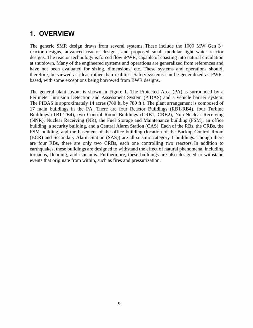
1. OVERVIEW
The generic SMR design draws from several systems. These include the 1000 MW Gen 3+
reactor designs, advanced reactor designs, and proposed small modular light water reactor
designs. The reactor technology is forced flow iPWR, capable of coasting into natural circulation
at shutdown. Many of the engineered systems and operations are generalized from references and
have not been evaluated for sizing, dimensions, etc. These systems and operations should,
therefore, be viewed as ideas rather than realities. Safety systems can be generalized as PWR-
based, with some exceptions being borrowed from BWR designs.
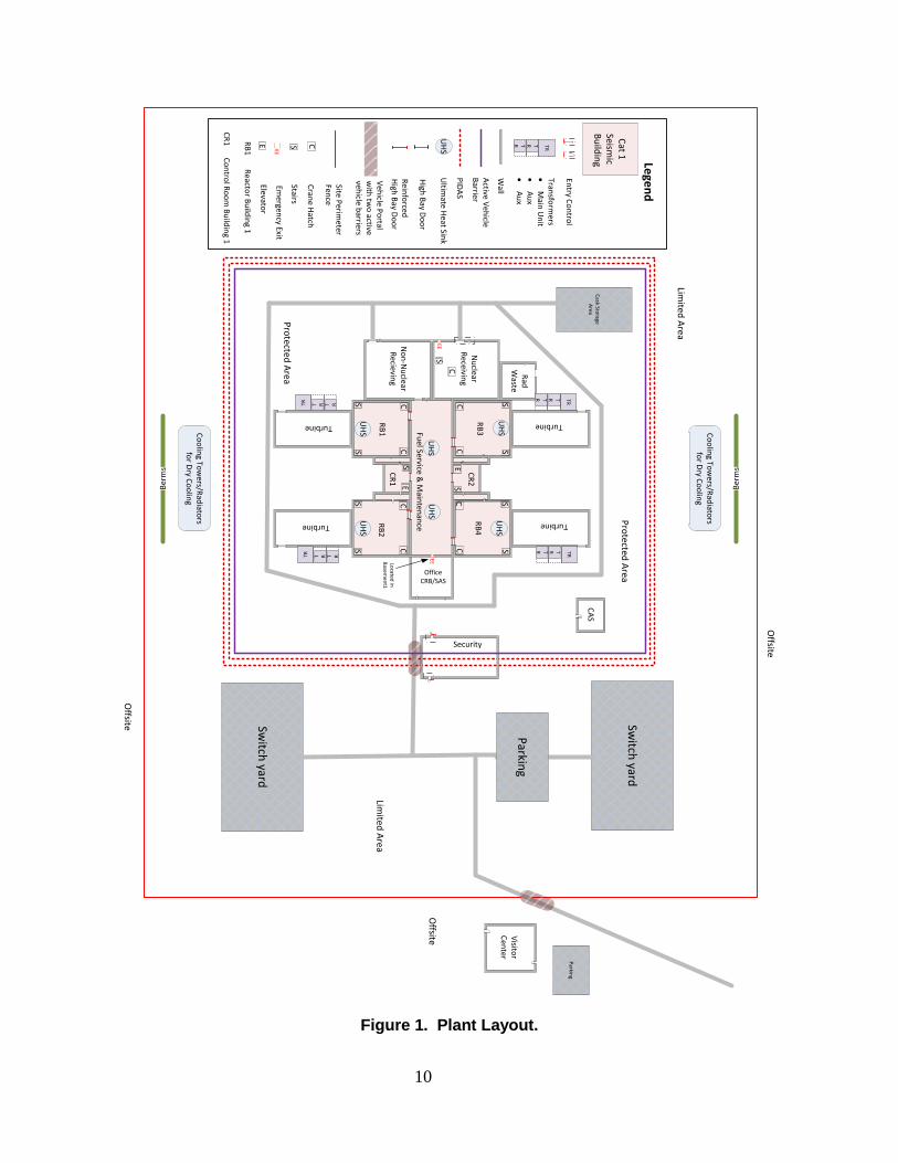
The general plant layout is shown in Figure 1. The Protected Area (PA) is surrounded by a
Perimeter Intrusion Detection and Assessment System (PIDAS) and a vehicle barrier system.
The PIDAS is approximately 14 acres (780 ft. by 780 ft.). The plant arrangement is composed of
17 main buildings in the PA. There are four Reactor Buildings (RB1-RB4), four Turbine
Buildings (TB1-TB4), two Control Room Buildings (CRB1, CRB2), Non-Nuclear Receiving
(NNR), Nuclear Receiving (NR), the Fuel Storage and Maintenance building (FSM), an office
building, a security building, and a Central Alarm Station (CAS). Each of the RBs, the CRBs, the
FSM building, and the basement of the office building (location of the Backup Control Room
(BCR) and Secondary Alarm Station (SAS)) are all seismic category 1 buildings. Though there
are four RBs, there are only two CRBs, each one controlling two reactors. In addition to
earthquakes, these buildings are designed to withstand the effect of natural phenomena, including
tornados, flooding, and tsunamis. Furthermore, these buildings are also designed to withstand
events that originate from within, such as fires and pressurization.
10
Figure 1. Plant Layout.
Turbine
Co
olin
g Tow
ers/Rad
iators
for D
ry Co
olin
g
Cask Sto
rage A
rea
Security
Switch
yard
Switch
yard
Ber
ms
Ber
ms
RB
1
Nu
clear R
eceiving
OfficeCRB/SAS
No
n-N
uclear
Recievin
g
Fuel Service &
Main
tenan
ce
CC
CC
CC
CC
E
SS
SS S
SS
S
S
CE
S
Turbine
Turbine
Turbine
S
UH
S
UH
S
UH
SU
HS
UH
S
UH
S
Visito
rC
enter
Parkin
g
CA
S
Rad
Waste
Co
olin
g Tow
ers/Rad
iators
for D
ry Co
olin
g
TR
TRTR
TR
TRTR
TR T R T R
TR T R T R
RB
2
RB
3R
B4
Parkin
g
Limited
Area
Pro
tected A
rea
CR
1
CR
2
EELocated
in
Basem
ent1
Limited
Area
Pro
tected A
rea
Offsite
Offsite
Offsite
EEU
HS
Cat 1
Seism
ic B
uild
ing
Entry C
on
trol
TR
TRTR
Transfo
rmers
·
Main
Un
it·
Au
x·
Au
x
Wall
PID
AS
Ultim
ate Heat Sin
k
RB
1 R
eactor B
uild
ing 1
Site Perim
eter Fen
ce
Lege
nd
CR
1 C
on
trol R
oo
m B
uild
ing 1
Active V
ehicle
Barrier
Veh
icle Po
rtalw
ith tw
o active
vehicle b
arriers
High
Bay D
oo
r
CC
rane H
atch
SStairs
EEEm
ergency Exit
EElevato
r
Rein
forced
H
igh B
ay Do
or
11
The nuclear island is arranged to control and minimize access of personnel/equipment entering
safety-related structures. Access to the nuclear island is restricted by security measures
throughout the complex. Safety-related equipment and nuclear material is placed below
grade. Movement of material and equipment between above-grade locations and below-grade
locations is only possible through the use of dedicated cranes. Movement below grade is
controlled through a number of access controls that compartmentalize both equipment and
personnel. The physical separation of safety systems from the associated access controls is a
fundamental characteristic of all SMR designs.
Outside the nuclear island, several other non-safety structures exist. These include the switch
yard, dry cooling radiators/cooling towers, cask storage area, parking, and the visitor
center. These buildings are all considered plant investment items and are protected as such.
1.1. Major Buildings and Structures
All buildings that house safety-related systems are designed to protect against natural phenomena
and design basis threats. Generally, all safety-related systems are placed below grade and below
a missile shield. Protection of structures, systems, and components from internally and externally
produced missiles is accomplished by the following practices:
1. Location of the system or component in a missile proof structure.
2. Physical separation of redundant systems.
3. Fire walls.
4. Flood mitigation building designs.
5. Prevention of internal missile production, when possible.
Systems that are needed to shut down the reactor, maintain reactor shutdown, and ensure the
containment of radioactive material require protection. These systems are:
1. Reactor Coolant Pressure Boundary (reactor pressure vessel, etc.),
2. Passive Decay Heat Removal System (UHS, CMT, OCP, etc.),
3. Decay Heat Removal System,
4. Automatic Depressurization System Relief Valves,
5. Control Rod Drive Scram System (hydraulic and electrical),
6. Fuel Pool Cooling and Cleanup System,
7. Control System (Remote Shutdown Panels, Control Room, Cables, etc.),
8. Reactor Protection System (depressurization system),
9. All Containment Isolation Valves,
10. Major Refueling Equipment (crane, etc.)
11. HVAC Emergency Chilled Water System,
12. HVAC Systems Required During Operation of Items (1) through (8), and
13. Electrical System for Operation of Items (1) though (12) (AC & DC).

12
1.1.1. Reactor Building
The reactor building is a seismic category 1 reinforced concrete structure with an approximately
100-by-100-foot footprint. The building is designed to protect safety systems from all design
basis threats, including aircraft impact. Furthermore, the building is designed to minimize
radiation exposure to plant workers and the release of radioactive material to the
environment. The building itself is composed of seven stories. Of these seven stories, five are
below grade. At grade level, a reinforced concrete missile shield protects the safety related sub-
floors from natural and hostile phenomena. The two floors above grade are constructed using
nominal commercial construction practices, and do not house any safety-related systems. These
floors house the non-safety grade, but preferred. power supply diesel generators, diesel tanks,
HVAC equipment, an Ultimate Heat Sink (UHS) tank, and a crane for moving equipment to the
lower floors. Movement of equipment to lower floors is accomplished by removing one of two
missile shield hatches. The removal of these hatches triggers an alarm in the CR and CAS.
Figure 2 shows a schematic of the two above-ground floors and roof.

13
Figure 2. Above Ground Reactor Building Floors.
Below grade, the building is divided into two sections by a two-foot-thick security-fire wall
having minimal penetrations. This division was incorporated into the design to prevent/slow the
propagation of antagonistic conditions to all redundant safety systems. Each floor contains a
number of rooms/compartments; safety-related systems are generally housed in one of these
locations. Due to the importance of such systems, access to each room is monitored.
Additionally, these rooms are designed to protect against fires, flooding, and design basis threats.
A second two-foot-thick concrete divider is installed between basement floor three and the
ceiling of basement floor four. This second divider protects a third set of redundant systems
located on the two bottom floors. These divisions are shown in Figures 3 and 4. Access from one
division to another can only be accomplished through the first basement floor of the FSM
building or through the above-grade floors in the reactor building. Equipment transfer between
levels is accomplished through removable hatches, much like the one at ground level. All hatches
ShieldHatch
C
S
C
S
HVAC
HVAC
ShieldHatch
C
S
C
S
HVAC
HVAC
HVAC
Crane Crane
Floor 1 Floor 2
LegendC=Crane Access HatchS=StairsUHS=Ultimate Heat Sink Reinforced High Bay Door
UHS UHS
Mis
c. E
qu
ipm
ent
Die
sel G
ener
ato
rs
Sto
rage
HVAC
HVAC
Roof
UHS
Diesel Diesel
Die
sel G
ener
ato
rs
Ven
tin
g
Die
sel G
ener
ato
rs
Ven
tin
g
14
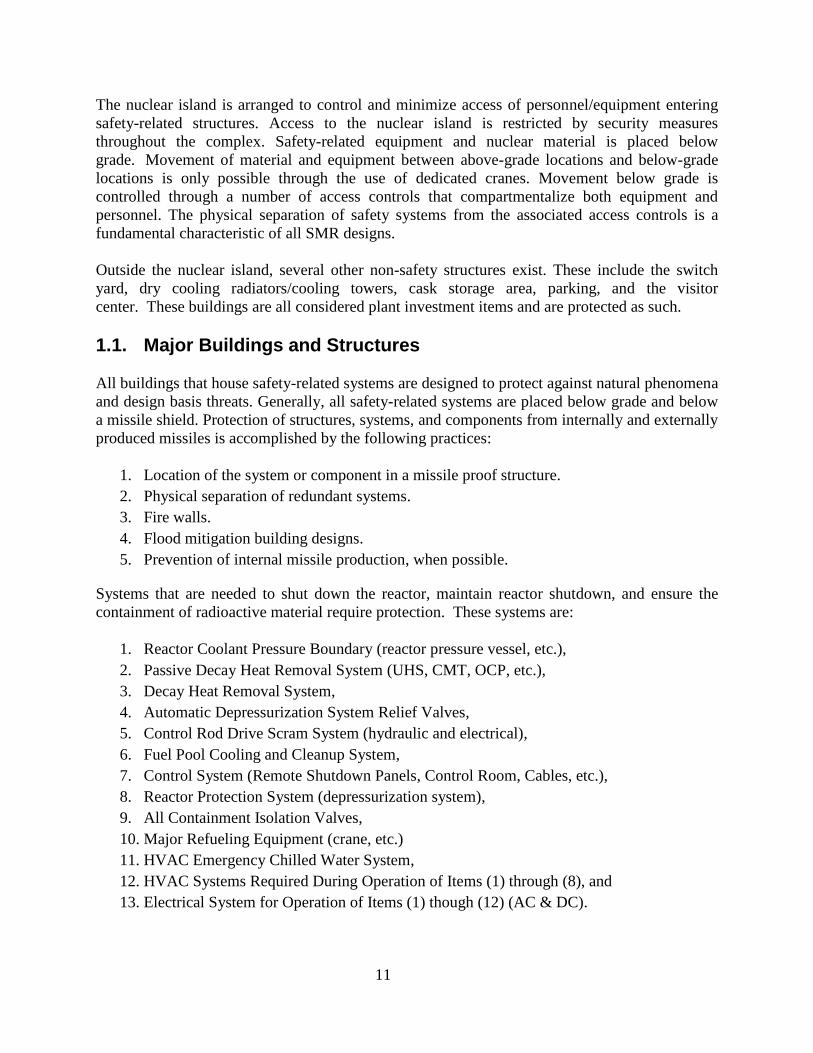
in the nuclear island are designed for fire and flood containment. Security engineered and
administrative controls are in place for each hatch and associated cranes. Personnel movement is
accomplished via two sets of stairs. Access from the stairwells to each floor is limited by access
controls.
Figure 3. Reactor Building, Safety Divisions 1 & 2, Basement Floors 1-3.
C
S
C
S
HVAC HVAC
Battery Bank
BatteryBank
Storage Storage
Storage Storage
I&C
Electrical
OCP OCP
Basement 3
CablesCables
Safety Division 2
Safety Division 1
Safety Division 3SD3
SD2
SD1
In Wall or Floor Cable Path Ways
First Division Cables go through the adjoining wall to the control building on the second basement floor
Second Division goes through the Fuel Handling building on the first basement floor
The third division comes up through the third basement of the control building
All divisions join either in the control room building or meet in the fuel service building on their way to the backup control room. This joining occurs on the first basement floor of the fuel handling building.
C
S
C
S
HVAC HVAC
Battery Bank
BatteryBank
Storage Storage
I&C
OCP OCP
Seco
nd
ary
Co
ola
nt
Containment
Basement 2
Cables Cables
HVACSystem
HVACSystem
I&C
Co
ntr
ol R
oo
m
Bu
ildin
g
C
S
C
S
HVAC HVAC
Battery Bank
BatteryBank
Storage Storage
Storage Storage
electrical
Elec
tric
al
OCP OCP
Basement 1
CablesCables
HVACSystem
HVACSystem
Co
ntr
ol R
oo
m
Bu
ildin
g
Co
ntr
ol R
oo
m
Bu
ildin
g
Containment
E
E=Equipment and Fuel CanyonC=Crane Access HatchS=StairsOCP=Outside Containment HatchI&C=Instrument and Controls Reinforced Gate
E
Containment
Seco
nd
ary
Co
ola
nt
Legend

15
Figure 4. Reactor Building, Safety Division 3, Basement Floors 4-5.
Each division has enough equipment to put the reactor into a safe shutdown. These systems
include Instrumentation and Control (I&C), HVAC, electrical systems, switch gears, and DC
battery banks. Other systems found in the reactor building include the high-pressure injection
pumps, lab space, spare batteries and equipment, and the chemical volume control system
(Cronje, 2012).
The reactor containment is housed in a concrete shielding structure centered in the reactor
building. The containment is a freestanding steel structure that houses the reactor pressure vessel
and associated systems. Access to the reactor during operation is not possible, and access during
shutdowns is tightly controlled. Access to the reactor is accomplished through a shield plug on
top of the shielding structure, personnel hatches, or the fuel/equipment canyon. The personnel
hatches are located just below grade, while the shield plug is located at ground level. The canyon
connects the RB and FSM building. Access is controlled by the reactor operator controls and the
R R
C
S
C
S
HVAC HVAC
Electrical
SwitchGears
Storage
Shut Down Panel
I&C
OCP OCP
C
S
LabsLabs
Containment
Basement 4
Basement 5
Cables Cables
BatteryBank
High Press
Pumps
High Press
Pumps
HVACSystem
Building Base Mat
Safety Division 2
Safety Division 1
Safety Division 3SD3
SD2
SD1
In Wall or Floor Cable Path Ways
First Division Cables go through the adjoining wall to the control building on the second basement floor
Second Division goes through the Fuel Handling building on the first basement floor
The third division comes up through the third basement of the control building
All divisions join either in the control room building or meet in the fuel service building on their way to the backup control room. This joining occurs on the first basement floor of the fuel handling building.
Sto
rage
Chemical Volume Control
Storage
E=Equipment and Fuel CanyonC=Crane Access HatchS=StairsOCP=Outside Containment HatchI&C=Instrument and Controls Reinforced Gate
Legend
16
health physics lockouts. In addition to the equipment associated with operations, several systems
related to passive safety are housed inside the shielding/containment structure. These include, but
are not limited to, makeup tanks, accumulators, residual heat removal heat exchangers.
The Outside Containment Pool (OCP) is housed external to the shielding structure. This body of
water is used during normal shutdowns for decay heat removal, as well as for severe accident
heat removal. A redundant heat exchanger system is used to transfer thermal energy from the
reactor system to the OCP. Additional cooling is accomplished using the ultimate heat sink tanks
that are located above grade.
The steam tunnel is located just below the missile shield, in between the two divisions of the
reactor building. The tunnel sends steam from the steam generators to the turbine building, and
transfers the corresponding condensed water back to the steam generators. Steam isolation valves
are located in both the containment building and the turbine building.
1.1.2. Control Room Buildings
The two operating CRs are located below grade, beneath a missile shield, and between each pair
of RBs. The operating CRs are only accessible via the below-grade level of the FSM. The main
CRs are able to control the plant during normal and design basis accidents. The CRs can regulate
both safety-related and non-safety-related systems. The CRB is composed of two below-grade
floors and one above-grade floor. The below-grade floors house the CR, auxiliary meeting room,
technical support center, alarm center, safety systems, emergency storage rations, a break room,
and hygiene facilities. Auxiliary facilities equipment, such as HVAC systems, are located on the
above-grade floor.
All controls are digital, with safety-related controls and instrumentation powered by a separate,
secure power source. In the unlikely event of a station black-out, passive safety systems, such as
compressed air and batteries, will allow for continued operation for no less than 72 hours; these
systems are located in the CRB on the lower floor. If more than 72 hours is needed, the BCR
could be used to increase this time to 1 week. Outside of a system blackout, the operating CRs
are serviced by redundant habitability systems. There are three trains of control cables, which are
physically separated for each reactor system except at the control building. Redundancy is
ensured at this point by a BCR located away from the RBs.
The BCR has access to all of the safety control systems for each of the four reactors. Certain
functions specifically related to plant startup cannot be accomplished from the BCR. The main
objective of the BCR is to maintain safe shutdown in the event the nominal operation CRs are
unavailable. Access to the BCR, and to the switch used to activate system control, is strictly
controlled. The BCR is located next to the SAS, on the bottom floor of the office building. The
same habitability and structure requirements are applicable to the BCR. The activation of the
BCR automatically scrams all four reactors and locks out the other operating rooms. Alarms
sound in the normal operating CR if access is granted to the BCR; additional alarms sound for
each procedural step taken when transferring reactor controls to the BCR. The CRB is shown in
Figure 5.

17
Figure 5. General Layout of a Control Room Building.
ESES
ES
Ground Floor Basement 1
Basement 2
HV
AC
HV
AC
Meeting Area
Control Room
Sto
rage
Sto
rage
ES
Bat
tery
/Nit
roge
n, e
tc
Cable LayoutRoom
Bat
tery
/Nit
roge
n, e
tc
Safety Division 2
Safety Division 1
Basement 3
Break RoomOffices
S
E
Stairs
Elevators
ReinforcedSecurity Door
Legend
18
1.1.3. Fuel Storage and Maintenance Building
The Fuel Storage and Maintenance (FSM) building is a seismic category 1 building. Access to
the RB and the operating CRBs is through the FSM below-grade floor. The FSM building’s
primary purpose is to store spent and new fuel (and related systems), and to provide for general
equipment storage, movement, and repair. Like other buildings in the nuclear island, a concrete
missile barrier is placed at grade. There are two main floors below grade. The first below-grade
floor (subbasement) is a series of walkways and equipment storage areas. This floor provides the
personnel access to the NR building basement, RBs, and operational CRBs. Access to each RB’s
subdivision is controlled and monitored by the CR and CAS. In case of major outages, temporary
personnel areas can be created and controlled using removable gates. This floor also allows for a
crane to move shielded fuel from the NR to the second subbasement floor.
On the second subbasement floor, a series of cranes and shielding systems allows for fuel
movement from fuel storage areas to and from the RBs. The connection to the RB for fuel and
equipment movement is secured during operation by interlocks and crane track disablement. This
floor also contains the safety systems for the spent fuel pool. These systems are located in
protected compartments having access controls. The only structures located below this floor are
for the spent fuel pool, fuel/equipment canyons, and new fuel vault. Figure 6 shows the general
layout of the FSM building.
There is an emergency exit (exit-only) in the FSM that personnel may use to exit from below
grade into the office building in the event of an emergency. Security cages on the emergency
exits prevent entry through them.

19
Figure 6. General Layout of the FSM Building.
High Bay
NF/
Cas
k
SFP
SFP
Crane
SFPSFP
Crane
Crane
NF/
Cas
k
Firs
t Fl
oo
rFi
rst
Bas
emen
t Fl
oo
rSe
con
d B
asem
ent
Flo
or
Thir
d &
Fo
urt
h
Bas
emen
t Fl
oo
r
Ground/ConcreteBorated Water Above Water
EE
Reinforced Gate or High Bay Door
EE
EmergencyExit
Legend
20
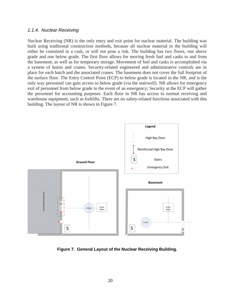
1.1.4. Nuclear Receiving
Nuclear Receiving (NR) is the only entry and exit point for nuclear material. The building was
built using traditional construction methods, because all nuclear material in the building will
either be contained in a cask, or will not pose a risk. The building has two floors, one above
grade and one below grade. The first floor allows for moving fresh fuel and casks to and from
the basement, as well as for temporary storage. Movement of fuel and casks is accomplished via
a system of hoists and cranes. Security-related engineered and administrative controls are in
place for each hatch and the associated cranes. The basement does not cover the full footprint of
the surface floor. The Entry Control Point (ECP) to below grade is located in the NR, and is the
only way personnel can gain access to below grade (via the stairwell). NR allows for emergency
exit of personnel from below grade in the event of an emergency; Security at the ECP will gather
the personnel for accounting purposes. Each floor in NR has access to normal receiving and
warehouse equipment, such as forklifts. There are no safety-related functions associated with this
building. The layout of NR is shown in Figure 7.
Figure 7. General Layout of the Nuclear Receiving Building.
Parkin
g/Un
load
ing A
rea
Ground Floor
Crane Hatch
S
Crane
S
Crane Crane Hatch
Basement
EE
Reinforced High Bay Door
S
EE
Stairs
Emergency Exit
High Bay Door
Legend

21
1.1.5. Non-Nuclear Receiving
NNR is the entry and exit point for all non-nuclear equipment and supplies. This is a one-story
building. Equipment and supplies are unloaded and transferred to the above-grade floor of the
FSM using either forklifts or cranes. The original shipping truck is not capable of driving into the
FSM. After traversing the FSM, equipment can be moved into an RB through secured, hardened
access panels on the RB’s first floor. Compensatory security measures are put in place when
these panels are opened, which is rarely. A parking and unloading area is located directly outside
of the NNR building. A small barrier separates this area from the NR parking/unloading area. An
area inside the NNR building is cordoned off to allow for temporary offices and break room
facilities. This building has no safety-related function. NNR is shown in Figure 8.
Crane
Parkin
g/Un
load
ing A
rea
Temporary Offices/Break Room Area
Figure 8. General Layout of the Non-Nuclear Receiving Building.
1.1.6. Turbine Buildings and Transformers
The turbine building is a non-safety grade structure, although it is protected as plant capital. This
building is based on traditional turbine building designs, but adds SMR characteristics, such as

22
modularity. The building has no personnel or equipment access points to the reactor building.
The only connection is a steam tunnel that cannot be accessed without major effort.
There are three transformers located next to the turbine building. The largest transformer is the
main step-up transformer. This transformer steps up the generated power, then sends that power
to the switchyard and subsequently to the grid. The next two transformers are the unit auxiliary
transformer and reserve auxiliary transformer (used as a backup to the unit auxiliary
transformer). These transformers power non-safety related systems/equipment. The transformers
step the AC power from the main generator down to the 6900V station bus voltage. The
transformers/generator system has a failure rate of 1/40 per operation year. The transformers are
surrounded by an 8-foot high chain-link fence. To prevent self-produced missiles affecting the
neighboring transformer, a mild steel barrier separates the transformers. A general layout of the
transformer building and associated transformers is shown in Figure 9.
Main Step Up Transformer
Unit Auxiliary
Transformer
Unit Auxiliary
Transformer
Chain Link Fence
Steel Barrier
TurbineGeneratorSecondary
Coolant
Piping to Cooling Towers/
Radiators
Basement of Reactor Building
Ground Floor of Turbine Building
Figure 9. General Layout of the Turbine Building.
1.1.6. Security Building
The security building provides entry control for personnel and vehicle access from the limited
area to the protected area of the plant. All personnel and vehicles are inspected for unauthorized
contraband, including explosives. Access controls are installed at the entry/exit portals and are
manned 24/7 with a minimum crew of two guards. In the event of an attack, the Entry Control

23
Point (ECP) can be locked on a time delay. This time delay is set to the time that it takes for off-
site law enforcement to arrive. The vehicle access entry point consists of hydraulic vehicle
barriers and reinforced gates. The security building straddles the PIDAS; however, the roof of
the building is alarmed to complement the detection coverage within the PIDAS.
The security building, as the name implies, houses the security force. The building is not a
seismic category 1 building, but is reinforced to a level that will deter a direct adversary attack.
Security personnel use the same personnel portals as the plant workers.
1.1.7 Central and Secondary Alarm Stations
The CAS and the SAS are located inside the protected area. The CAS is not a seismic category 1
building, but is reinforced to a level that will deter a direct attack. All alarms are annunciated,
assessed, and communicated to the on-site and off-site response forces. All personnel access
points into the CAS and SAS are positively controlled; these points are locked 24/7.
1.1.8. Radioactive Waste Building
The radioactive waste building houses waste from nominal plant operations. The building is not
safety-related and does not house any material that requires a seismic category 1 structure. The
building does pose a dirty bomb target, therefore it is located inside the protected area. The
building generally stores solid waste, but can house liquid waste for short periods of time. The
building has the capability to turn liquid waste into concrete for shipment. Entry into the building
is managed through access controls.

24
1.2. Major Plant Components
1.2.1. Reactor System
The reactor is a forced-flow iPWR that is capable of using natural circulation at shutdown. It can
produce 300 MWe or 1000 MWth, and operates with a two-year conventional fuel cycle.
1.2.2. Shielding Structure and Containment
The shielding structure is a large, circular, self-standing structure located in the center of the
reactor building. The building is not built to withstand pressure transients, but rather to serve as a
radiation shield and as physical protection to the reactor pressure boundary. The shielding
structure's concrete base mat is an integral part of the reactor building's base mat. The foundation
is 20 feet thick, while the walls are approximately 4 feet thick. This structure is designed to be a
low-leak system. The shielding structure is approximately 15 meters in width and 30 meters
high. The number of penetrations through the shield walls is minimized to decrease the amount
of radiation exposure to plant workers. Access is possible through a single personnel interlock,
through a large equipment hatch at the top of the structure, and through the nominal refueling
canyon. This entire structure is located below grade. Major penetrations in this structure are for
the steam tunnel, I&C cables, and passive heat-removal piping.
Inside the shielding structure sits the steel containment vessel. The steel containment vessel is
built to withstand pressures up to 1.7MPa. The number of penetrations into the containment
vessel is minimized; penetrations are generally only related to the secondary system (exceptions
include the chemical volume control system and the high pressure injection systems). The
limited penetrations into the primary system are automatically isolatable by the reactor
containment isolation system. The containment vessel sits in a pool of water at the bottom of the
concrete structure. This pool of water is an integral part of the passive safety feature, because it
acts as heat sink and greatly increases the rate of heat transfer from the containment vessel
during the most severe of accidents. There is no heat exchanger in this pool. The pool also helps
with radiation shielding.
1.2.3. Fuel Storage
The new-fuel storage area is located in the FSM building in the new-fuel storage vault. The fuel
storage vault is near the spent fuel pool and the cask preparation facility. The quantity of fuel
stored at any one time is 40% of the fuel needed to run all reactors onsite, but is separated by
reactor destination. The fuel is stored in high-density racks submerged in borated water (the
borated water is not required for reactivity control). The new-fuel racks are designed to maintain
sub-criticality (k<.95) under both normal and abnormal conditions. Each reactor new fuel section
is designed to limit the amount of fuel removed at any one time by a time lock on the crane, so
that only a single reactor’s new fuel can be moved without encountering a time delay. The new
fuel storage vault has a separate HVAC system that monitors for radioactivity. If radioactivity is
detected, the vault and HVAC system are isolated to prevent a release.
25
Procedures for fuel handling dictate that no more than one assembly can be handled above the
racks; this is accomplished using weight controls. The crane for fuel movement can be used for
heavier loads, but, when doing so, is unable to cross the pool where the racks are located.
Furthermore, the height and speed at which the fuel can be moved is also regulated. The crane is
restricted through a series of electric interlocks so that fuel cannot be raised above the water,
thereby bypassing the shielding requirements.
The spent fuel pool is located below grade in the fuel service building. The pool is approximately
40 feet deep and is sized to contain 15 full core loadings (in the case of a 4 module design). The
spent fuel is stored in low-density racks that are submerged in a minimum of 20 feet of water.
The racks are designed such that natural circulation occurs before the fuel reaches 100°F. The
spent fuel pool is a seismic category 1 structure, constructed with walls 6 feet thick and having a
one-half-inch thick steel liner. The spent fuel pool and associated canyons are designed such that
water from the canyons drains and circulates into the pool. Low-density racks are also used for
the spent fuel pool, in an arrangement to ensure that reactivity is less than .95; no credit is taken
for burnup.
Pool gates, as well as fill and drain lines, are located at a height to ensure adequate water for
shielding purposes. The circulation and filter lines for the spent fuel pool cooling and cleanup
system (SFP-CCS) are designed to ensure that the pool cannot be drained through the use of
vacuum breakers. Recirculation pumps remove decay heat from the spent fuel pool. The
recirculation pump sends the pool water to a heat exchanger. A separate redundant heat
exchanger can remove heat from the pool to one of the ultimate heat sinks. The pumps for the
SFP-CCS are not safety-related.
1.2.4. Refueling Equipment
The refueling machine is a gantry crane used to transport fuel and reactor components to and
from the pool storage area. This crane is separate from the spent fuel pool crane.
Preprogrammed location limiters are used to prevent the crane from damaging equipment. A
retractable vessel platform is available for vessel inspection. The platform must be moved from
its resting area to an associated tract system by the containment crane. A large amount of tools
and auxiliary equipment are available for the refueling process, including wrenches, slings,
grapples, etc. All major machine movements (crane/platforms) are controlled by a local operator
and monitored by the CR.
1.3. Miscellaneous Balance of Plant and Supporting Systems Design
1.3.1 Cask Storage Pad
The cask storage pad is located inside in the protected area. It is meant to store 20 years of spent
fuel casks. If additional storage is needed, proposed ideas include an annex to the protected area,
or off-site storage. The pad is a reinforced concrete structure, capable of meeting the load
weights of casks with overpacks placed in a 4-by-4-meter pattern. There is no additional security
or gating around this area, because the overpacks and casks provide adequate protection for
design basis attacks.
26
1.3.2. Cooling Towers/Dry Cooling Radiators
Depending on the site location, either cooling towers or dry cooling radiators could be utilized.
Cooling towers are typically constructed of reinforced concrete, while radiators are metal piping
structures.
The inclusion of dry cooling radiators in the plant design is an advanced feature of SMRs. These
radiators allow for heat rejection to the environment without the loss of water inventory or the
need for large bodies of water. The radiators use high efficiency fans, powered from an offsite
source to ensure that any surge from the fan motors and controls will not affect the power plant’s
safe shutdown. The radiators are designed such that they are only required to function at 80%
efficiency to accomplish heat rejection during full-power conditions. The radiators are arranged
to increase natural airflow, while berms are installed to prevent direct vehicle assault.
1.3.3. Switchyard
There are two switchyards. Each switchyard is subdivided into separate yards, each with access
control. Each subdivision accounts for one reactor. The switchyard is located in the limited area,
protected by a 10-foot high chain-link fence topped with razor wire.
27
2. KEY COMPONENTS OF THE PASSIVE CORE COOLING SYSTEM
The reactor was designed to have a low power density, which allows for the core to be cooled
through natural circulation during shutdown and design basis accidents. The Passive Core
Cooling System (PCCS) is composed of several components, including core makeup tanks,
outside containment pool, and the UHS tanks. The reactor system uses redundant Core Makeup
Tanks (CMTs) that are located inside of containment. These tanks are able to immediately inject
water at high pressure into the pressure vessel. The injection of high-pressure water is done only
when AC power is available. If AC power is not being provided, the system can passively inject
low-pressure water into the system. For this to occur, the reactor system must be depressurized.
The CMTs are connected to the Outside Containment Pool (OCP), and heat is transferred from
containment to this pool through a series of redundant heat exchangers. The OCP is allowed to
boil off, and is constantly being refilled by the ultimate heat sink tanks located outside the
reactor building. An overview of this process is shown in Figure 10.

28
Figure 10. Passive Safety Design.
2.1 Core Makeup Tanks
The bottoms of these tanks are connected to the reactor vessel through a direct vessel injection
system. A heat exchanger inside each of these tanks is connected to the outside containment
pool. The water in these tanks is significantly cooler than the primary core water, so that when
the injection lines open, the heavy colder water that enters near the top of the pressure vessel
begins a natural circulation loop in the primary pressure vessel.
CORE
CMT
CMT
OCP
Ultimate Heat Sink
On Top of Reactor Building
OCP
Shared Ultimate Heat Sink
On Top of Control Room Building
Missile Barrier
Heat Exchanger
Valve Closed
Valve OpenSteam to Atm
Prior to Accident
Filling of Containment
CORE
CMT
CMT
OCP
Ultimate Heat SinkOn Top of Reactor Building
OCP
Shared Ultimate Heat Sink
On Top of Control Room Building
Steam to Atm
CORE
CMT
CMT
OCP
Ultimate Heat SinkOn Top of Reactor Building
OCP
Shared Ultimate Heat Sink
On Top of Control Room Building
Steam to Atm
Heat Removal
CMT TankCMT
Pressure Vessel
Shielding Structure
Containment Structure

29
2.2. Outside Containment Pool
The Outside Containment Pool (OCP), not to be confused with the pool located at the bottom of
the shielding structure, is connected to the CMTs through redundant heat exchangers. These heat
exchangers are always in operation, and can only be closed in the case of a line breach. A line
breach is not expected to occur inside containment, but rather outside containment; a double
breach is outside of the design basis. There is a set of three heat exchanger lines, only two of
which are needed for full decay heat removal. Steam from the OCP is sent through a HEPA filter
to the atmosphere, and is monitored from the Control Room for radionuclides.
The OCP holds approximately 28000 cubic feet of ordinary water. The tank’s base is ~400
square feet and rises ~70 feet. This is enough water to cool the reactor system after operating for
two years at a power level of 1200 MWth (with a safety margin).
2.3. Ultimate Heat Sink
The OCP is connected to two ultimate heat sinks (UHSs). The UHSs are tanks of water that are
used to refill the OCP. As stated above, one ultimate heat sink is shared (SUHS), while another is
the primary UHS (PUHS) for each reactor unit. Both UHSs are connected to the OCP in a
redundant fashion. The connection is designed such that these OCP-UHS lines are always open,
constantly ensuring that the OCP is filled. The manual closing of these lines sounds an alarm in
the CR.
The ultimate heat sinks are steel tanks located above the missile shield in the reactor building or
the fuel handling building. The tank located in the reactor building is ~20 feet in diameter and
60 feet tall. This tank holds ~2000 cubic feet of water, enough water to cool a reactor system for
an additional four days. The shared tanks are located in the FSM building above the ground and
the missile shield. These tanks offer redundancy for UHS tanks located in the reactor building.
Each tank can provide four days of cooling, with the shared tank capable of providing eight days.
The tanks are used to fill the OCP. Furthermore, the tanks can be filled by an external water
source. The pumps for filling the tanks are operated outside the PIDAS. The shared tanks can
also be used to send makeup water to the spent fuel storage pool.
2.4. Pressure Relief System
The Pressure Relief System (PRS) automatically depressurizes the reactor system in the event of
a loss-of-coolant accident (LOCA), in which the CMT systems fail to maintain the reactor vessel
water level. The depressurization of the nuclear system allows the low-pressure flooder systems
to supply enough cooling water to adequately cool the fuel. This system is not part of the
nominal passive safety procedures.
30
3. OTHER SAFETY SYSTEMS
3.1 Decay Heat Removal System
Decay heat removal during normal operation is accomplished via the passive system, which is
used unless there is a loss of offsite power. The system is essentially the same as the passive
decay system, but uses a pump to enhance the the passive system’s effectiveness. These pumps
are located on a line parallel to the lines that connect the CMTs and OCP. Additionally, two heat
exchangers are installed in the OCP that is connected to a radiator on top of the reactor building.
This system is also powered by an electrical pump. The operation of this system decreases the
OCP temperature, preventing significant loss of water inventory due to evaporation.
3.2 Instrument & Controls (I&C) and Safety Control & Instrumentation
System (SCIS)
The safe operation of the plant requires a system to ensure that vital functions occur. Non-safety-
related controls and associated instrumentation are controlled by the I&C system. While the I&C
is important, not all I&C is directly related to safety, and must be built accordingly. The Safety
Control and Instrumentation System (SCIS) is a subcategory of the I&C system. This system is
charged with ensuring the control of reactivity, removal of heat from the core, and containment
of radioactive material. This plant design uses a fully digital control/instrumentation system. The
SCIS is housed in the RB, the CRB, and, to a limited extent, in the BCR (located in the basement
of the office building).
These systems control reactivity within operational limits, prevent transients, shut down the
reactor system, and maintain system shutdown within the design basis threat conditions. The
systems also control all of the valves and pumps related to both the passive safety systems and
the decay heat removal systems for both the reactor and the spent fuel pool. Finally, the system is
charged with isolating the reactor pressure vessel, the containment, and the reactor/FSM
buildings. Building closure is initiated by HVAC controls.
3.3. AC Power
An AC electrical power distribution system provides reliable power to the plant for all nominal
operations, including startup, operation, shutdown, and outage operations. The plant does not
require offsite AC electrical power to cope with design basis accidents. In the case of a loss of
offsite power, a safety set of diesel generators will start automatically. These diesel generators
can power all safety systems indifferently (with refueling). A second set of generators can also
provide power. These generators are not safety-related and are generally stored off site. When
installed, these systems are referred to as Preferred Primary Power (PPP), and the safety diesel
generators become a redundant safety system. The safety diesel generators are located on top of
the control building at a height that protects them from flooding. Due to the smaller and less
demand load of SMR designs, the diesel generators can use air-cooling. Air-cooling reduces
complexity, as well as cost, while increasing the reliability of the system.

31
The AC power system is designed redundantly, as are all safety components. The system is a
class 1E power system with three divisions, with any two divisions being adequate to place the
unit in a hot shutdown condition. A system of protective relays allows for the isolation of
malfunctioning equipment. Voltage relays are used on safety-rated systems for the disconnection
of AC power and the connection of emergency battery power. All safety-related breakers,
generators, transformers, and circuits can be monitored and/or controlled via the CR. The class
1E power load is divided into three divisions, with each division joined to an independent class
1E bus. These divisions have access to one onsite power source, two offsite power sources, and
the alternate PPP source. The safety systems that are connected to this power system are:
1. Safety System Logic and Control Power Supplies, including the Reactor Protection
System,
2. Core and Containment Cooling Systems,
3. Safe Shutdown Systems, and
4. Class 1E Monitoring Systems.
3.4. Reactivity Control System
Reactivity is normally accomplished through electrically driven control rods (i.e, the Reactor
Protection System (RPS)). The reactor protection system uses the fine movement control rod
drives to insert control rods into and remove control rods from the reactor. In the case of an
operator-signaled or an RPS automatic scram, these motors quickly drive the control rods into
the core, thus shutting the reactor down. If control cannot be regained gained by the RPS, the
Alternate Rod Insertion (ARI) function can be used. Through a series of automatic signals
related to the failure of the RPS and/or operator command, the ARI causes a hydraulic scram.
Both of these systems can respond to transients. A third system, the standby liquid control
system (SLCS), can be used for non-transient control.
3.5. Standby Liquid Control System
If the operator cannot shut down or ensure the continued shutdown of the reactor system, the
SLCS can be used to bring the reactor to shutdown by the addition of borated water. This system
is a safety-related system. The system is not capable of SCRAM or any other fast reactivity
transients. The system is tested periodically using non-borated water. The system is exercised
through automatic reactor alarms or by operator actions. The system is operable any time the
reactor can reach criticality. Procedural system locks are used to ensure the unintentional
operation of the system by operators. The borated water is injected through a high-pressure line.
The pressure is sufficiently high to overcome any postulated reactor environmental conditions.
The system is located in the reactor building in safety division three.
3.6. Core Thermal-Hydraulic Internals
As an integrated PWR design, there are no pumps located inside the pressure vessel. Major
components include the down comer, steam generator, core support structure, pumps, pressure
valves, water makeup lines, instrumentation components, and chemical control lines. All these
systems are safety-related and failure of any one of these systems results in a scram. The reactor
32
system is brought to operating pressure and temperature through a series of fine control rod
movements. The reactor system cannot be brought to significant power production at non-
operating temperatures/pressures and without the secondary system in operation.
3.7. Safety Related HVAC
The HVAC Emergency Cooling Water system (HECW) provides chilled water to the safety-
related equipment in the reactor building, fuel service building, control building, and the control
building habitability area. The system is designed to work under both normal and abnormal
reactor conditions. The system is powered from Class 1E buses. In the event of abnormal
conditions, the system can be powered from the Alternate AC power source (AAC). The system
is housed in a category 1 seismic building, protected from missiles. The system is both robust in
design,, as well as protected from non-nominal power supply conditions (surges) and short
transient operations. Fill tanks and associated equipment are designed to prevent drainage
through operation.
The system is subdivided into three redundant subsystems; any two can provide enough cooling
to the control building and to all redundant safety-related systems. A single subsystem can cool
one train of redundant safety systems and maintain the habitability of the Control Room and the
associated operating envelope. The associated envelope is large enough to allow personnel to
move in and out of the control building, but the habitability of non-critical floors/facilities will
not be ensured. Each subsystem is physically separated, with one system located in each of these
buildings: control building, reactor building, and fuel facility. Each piece of equipment needing
to be served by this HVAC system is served by no fewer than three fan coil units (one related to
each of the three HVAC subsystems previously mentioned). The system is initiated after
ensuring that the secondary containment isolation signal has been received. An example of the
subsystem division is shown below.
1. Safety-Related Subsystem Division A
(1) Safety-related battery Division I.
(2) HECW chiller Division A.
(3) Decay Heat Removal water pump and heat exchanger Division A.
(4) HVAC equipment Division A.
(5) Safety-related electrical equipment Division I.
(6) Non-safety-related power supplies.
(7) Non-safety-related electrical equipment.
3.8. Primary Containment Service Air System
The Primary Containment Service Air System (PCSAS) is a safety-related system, and therefore
a category 1 seismic system. The system is redundantly designed to ensure primary containment
air quality for normal operation. The PCSAS is used to keep the containment and the shielding
structure at a negative atmospheric pressure during outages. When the plant is operating, this
33
system is used only for the shielding structure’s maintenance of negative pressure. Air quality
inside this structure is not maintained due to the high radiation field preventing occupation.
3.9. Fire Containment/Control System
Reactor safe shut-down equipment is divided into redundant systems, each capable, by itself, to
shut down the reactor safely. This is accomplished through plant arrangement, redundant safety
system separation, fire containment/suppression, personnel access, alarm, and HVAC controls.
In terms of fire control, each system is separated by firewalls to prevent any single fire from
removing the redundancy. All doors, walls, floors, and ceilings are rated for a three-hour fire.
Overpressure protection is accomplished by blowout panels. Blowout panels, HVAC, and cable
routing for safety-related equipment are separated into their given fire control division. These
divisions are directly related to the redundant safety subsystems. The only place where these
subsystems meet is at the CR; redundancy at this location is ensured by the BCR. Furthermore,
the effect of spurious responses resulting from the effects of a fire is prevented by using a dual
channel digital system, where two identical signals are required at the de-multiplexer for the
control signal to be recognized. Fire suppression is provided by sprinklers, an AFFF sprinkler
system, alarms, detectors, portable firefighting equipment, and other generally expected systems.
Fire in containment is not possible during operation, due the inert nature of containment. Special
procedures and precautions are taken when containment is not inert.
3.10. Communication Equipment
The reactor facility has several communication systems throughout. Due to the robustness of the
site structure and safety concerns, wireless communication is prevented. Two hard-wired
systems are typically available, depending on the local function. The first system is a site-wide
powered communication line. The second is a sound-powered telephone system that is used in
areas of the facility that are safety related. Furthermore, the site contains a third paging system
that resides on its own dedicated transmission network, which allows for communication during
normal operations. The only safety-related system is the sound-powered telephone system.
34
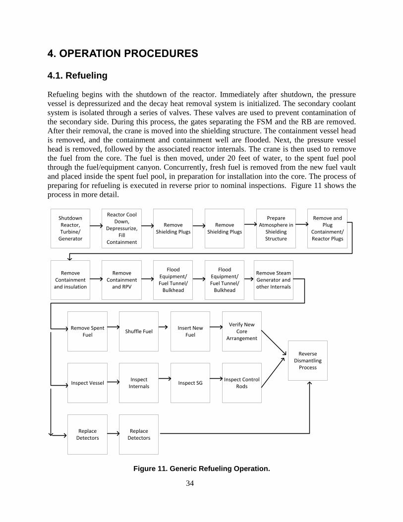
4. OPERATION PROCEDURES 4.1. Refueling
Refueling begins with the shutdown of the reactor. Immediately after shutdown, the pressure
vessel is depressurized and the decay heat removal system is initialized. The secondary coolant
system is isolated through a series of valves. These valves are used to prevent contamination of
the secondary side. During this process, the gates separating the FSM and the RB are removed.
After their removal, the crane is moved into the shielding structure. The containment vessel head
is removed, and the containment and containment well are flooded. Next, the pressure vessel
head is removed, followed by the associated reactor internals. The crane is then used to remove
the fuel from the core. The fuel is then moved, under 20 feet of water, to the spent fuel pool
through the fuel/equipment canyon. Concurrently, fresh fuel is removed from the new fuel vault
and placed inside the spent fuel pool, in preparation for installation into the core. The process of
preparing for refueling is executed in reverse prior to nominal inspections. Figure 11 shows the
process in more detail.
Figure 11. Generic Refueling Operation.
Shutdown Reactor, Turbine/
Generator
Reactor Cool Down,
Depressurize, Fill
Containment
Remove Shielding Plugs
Remove Shielding Plugs
Prepare Atmosphere in
Shielding Structure
Remove and Plug
Containment/Reactor Plugs
Remove Containment and insulation
Remove Containment
and RPV
Flood Equipment/Fuel Tunnel/
Bulkhead
Flood Equipment/Fuel Tunnel/
Bulkhead
Remove Steam Generator and other Internals
Remove Spent Fuel
Shuffle FuelInsert New
Fuel
Inspect VesselInspect
Internals
Replace Detectors
Replace Detectors
Verify New Core
Arrangement
Inspect SGInspect Control
Rods
Reverse Dismantling
Process
35
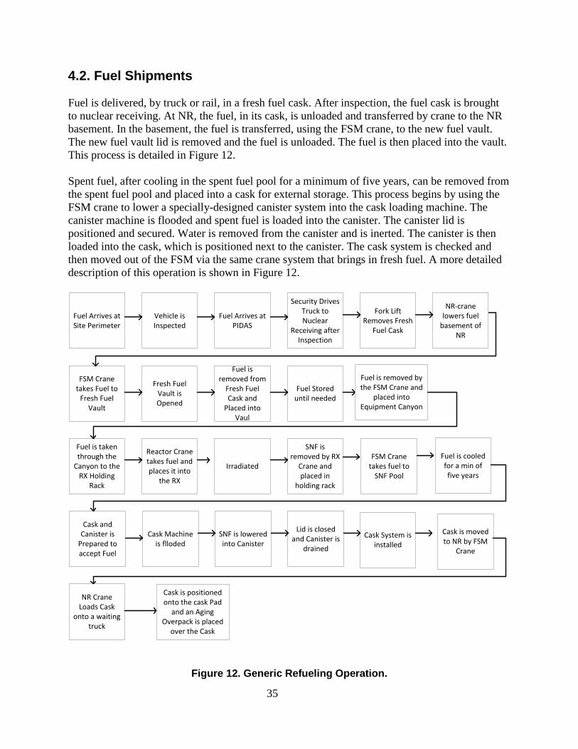
4.2. Fuel Shipments
Fuel is delivered, by truck or rail, in a fresh fuel cask. After inspection, the fuel cask is brought
to nuclear receiving. At NR, the fuel, in its cask, is unloaded and transferred by crane to the NR
basement. In the basement, the fuel is transferred, using the FSM crane, to the new fuel vault.
The new fuel vault lid is removed and the fuel is unloaded. The fuel is then placed into the vault.
This process is detailed in Figure 12.
Spent fuel, after cooling in the spent fuel pool for a minimum of five years, can be removed from
the spent fuel pool and placed into a cask for external storage. This process begins by using the
FSM crane to lower a specially-designed canister system into the cask loading machine. The
canister machine is flooded and spent fuel is loaded into the canister. The canister lid is
positioned and secured. Water is removed from the canister and is inerted. The canister is then
loaded into the cask, which is positioned next to the canister. The cask system is checked and
then moved out of the FSM via the same crane system that brings in fresh fuel. A more detailed
description of this operation is shown in Figure 12.
Figure 12. Generic Refueling Operation.
Fuel Arrives at Site Perimeter
Vehicle is Inspected
Fuel Arrives at PIDAS
Security Drives Truck to Nuclear
Receiving after Inspection
Fork Lift Removes Fresh
Fuel Cask
NR-crane lowers fuel
basement of NR
FSM Crane takes Fuel to
Fresh Fuel Vault
Fresh Fuel Vault is Opened
Fuel is removed from
Fresh Fuel Cask and
Placed into Vaul
Fuel Stored until needed
Fuel is taken through the
Canyon to the RX Holding
Rack
Reactor Crane takes fuel and places it into
the RX
Irradiated
Cask and Canister is
Prepared to accept Fuel
Cask Machine is flloded
Cask is moved to NR by FSM
Crane
NR Crane Loads Cask
onto a waiting truck
SNF is removed by RX
Crane and placed in
holding rack
SNF is lowered into Canister
Lid is closed and Canister is
drained
FSM Crane takes fuel to
SNF Pool
Fuel is removed by the FSM Crane and
placed into Equipment Canyon
Fuel is cooled for a min of five years
Cask System is installed
Cask is positioned onto the cask Pad
and an Aging Overpack is placed
over the Cask
36
4.3. Personnel Entry and Exit
Access control begins at the site perimeter fence. The only access point from offsite to the plant
site limited area is through the gate near the visitor center. The only access from the limited area
to the protected area is through the ECP in the security building. All personnel, including
security personnel, access the protected area through this protected area ECP. A thorough
inspection of personnel and vehicles for unauthorized contraband, including explosives, is
carried out before entry is authorized. Subsequent entry into any of the buildings is tightly
controlled, with all safety-related structures further controlled.
Within the protected area, there is restricted access through the rear of the office building to the
above-grade floor of the following: the FSM, the two main CRs, NR, and NNR (a single-story
building). Only dedicated internal vehicles (i.e., forklifts) can move between NNR and the
above-grade floor of the FSM.
There is only one ECP to below grade located at the NR building. It allows personnel restricted
access to below grade via the stairwell. Although the RBs do have stairwells that go all the way
up to the above-grade floor, there are secure, hardened access panels between the above-grade
floor of the FSM and the above-grade floor of the RBs. This prevents access from the above-
grade floor of the FSM to the stairwells that go all the way down to the reactors. Compensatory
security measures are put in place whenever the access panels are opened (rarely) to allow items,
such as replacement parts, to be moved from NNR via the above-grade floor of the FSM to one
of the RBs.
Within each RB, access to inside the reactor can be gained through crane hatches for items, or by
staircases for personnel. The staircases are monitored by the CAS. Opening the crane hatches
will trigger a scram if the plant is operating, with immediate initiation of the alarms in the CRs
and CAS.
There are two “exit-only” emergency exits that personnel may use to exit from below grade in
the event of an emergency. Each of the emergency exits is equipped with a security cage to
prevent entry through them. The west side emergency exit is through NR; the east side
emergency exit is from the FSM through to the office building. After exiting, personnel will be
gathered by security for accounting purposes.
4.4. Security Systems
The site perimeter is bounded by an 8-ft chain linked fence with razor wire on top. The site
perimeter is not alarmed, but the area is randomly patrolled inside the perimeter by the guard
force. The protected area is surrounded by a PIDAS. The PIDAS includes the appropriate
technology to detect and assess unauthorized access. All alarm devices and transmission lines are
tamper-indicating and self-checking to provide an automatic indication when an alarm system (or
alarm system component) fails, or when the system is operating on back-up power. The intrusion
detection system is used to initiate a timely response against an adversary threat. Passive and
active vehicle barrier systems are located inside the inner fence of the PIDAS to prevent
37
unauthorized entry of various sizes of vehicle into the PA. The PIDAS and PA are illuminated at
all hours by a series of lights located inside the PIDAS. Each light is capable of operating in a
diminished capacity by using solar powered batteries as backup power in the case of a station
blackout.
The nuclear island and all safety-related equipment are located below grade, inside the PA. The
below-grade siting is a key feature that provides enhanced security and safety to SMR designs.
There is only one ECP to below grade located at the NR Building. Both the ECP leading below
grade and the ECP at the security building into the PA are manned 24/7 with a minimum crew of
two. In the event of an attack, the entry point can be locked on a time delay. This time delay is
set to the time that it takes for off-site response to arrive. All access control is monitored for
personnel entering and exiting the buildings in the PA for emergency preparedness and security.
All ECPs and sensitive areas are monitored by closed-circuit television (CCTV) cameras.
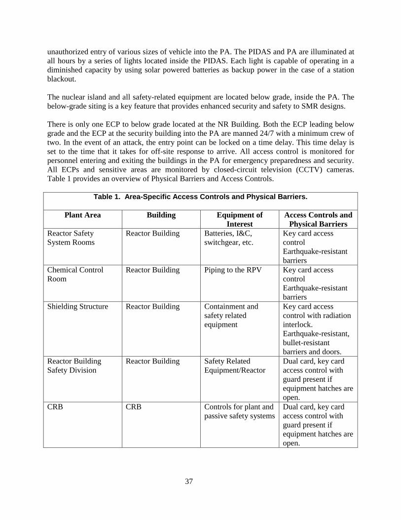
Table 1 provides an overview of Physical Barriers and Access Controls.
Table 1. Area-Specific Access Controls and Physical Barriers.
Plant Area Building Equipment of
Interest
Access Controls and
Physical Barriers
Reactor Safety
System Rooms
Reactor Building Batteries, I&C,
switchgear, etc.
Key card access
control
Earthquake-resistant
barriers
Chemical Control
Room
Reactor Building Piping to the RPV Key card access
control
Earthquake-resistant
barriers
Shielding Structure Reactor Building Containment and
safety related
equipment
Key card access
control with radiation
interlock.
Earthquake-resistant,
bullet-resistant
barriers and doors.
Reactor Building
Safety Division
Reactor Building Safety Related
Equipment/Reactor
Dual card, key card
access control with
guard present if
equipment hatches are
open.
CRB CRB Controls for plant and
passive safety systems
Dual card, key card
access control with
guard present if
equipment hatches are
open.

38
Table 1. Area-Specific Access Controls and Physical Barriers.
Plant Area Building Equipment of
Interest
Access Controls and
Physical Barriers
Cable Spreading
Room
Control Building Cables for control of
plant operating
systems and
engineered safety
features.
Key card access
control
Earthquake-resistant
barriers.
Control Room CRB Second
basement
Controls for plant and
passive safety systems
Key card access
control. Bullet-
resistant walls, doors,
ceiling, floor, and
windows.
Scram Relay Room Control Building First
Basement Floor
Relays and logic
cabinets for Reactor
Protection System
(SCRAM) system.
Key card access
control.
Ultimate Heat Sink Roof of Reactor
Building
Water required for
passive safety after
72 hours.
Double-wall tank,
24-inch concrete wall,
earthquake-resistant
barrier. Lock-and-key
access control to
valves, and other
insider sabotage
targets.
Fuel Storage and
Maintenance Building
Fuel Storage and
Maintenance Building
Spent Fuel Pool/Fresh
Fuel Vault
Dual card, key card
access control with
guard present.
Earthquake-resistant
barriers.
Turbine Building Turbine Building Plant Capital
Protection Equipment
Key card access
control.
Earthquake-resistant
barriers.
The guard force protection strategy comprises three types of security personnel: a dedicated,
armed, on-site response force located below grade of the nuclear island to implement a below-
grade denial strategy during an adversary attack; an armed guard force to support CAS/SAS
functions, patrol the PA, and establish a containment strategy during an adversary attack; and
local law enforcement for tertiary response during an adversary attack.
39
5. BIBLIOGRAPHY
1. Cheng, L. Y. (2008). IRIS (International Reactor Innovative and Secure).
2. Cronje, J. M. (2012). Overview of the Westinghouse Small Modular Reactor Building
Layout. Chicago: Proceedings of ICAPP '12.
3. Department of Energy: Office of Civilian Radioactive Waste Management. (2008). Yucca
Mountain Repository License Application: Safety Analysis Report . Las Vegas:
Department of Energy.
4. Galyean, B. (2012). Containment Functional Requirements. Corvalis: NuScale Power.
5. General Electric. (1997). ABWR Design Control Document. General Electric.
6. John Darby, K. H. (2007). Framework for Integrating Safety, Operations, Security, and
Safeguards in the Design and Operation of Nuclear Facilities. Albuquerque: Sandia
National Laboratories.
7. Matthew J. Memmott, C. S. (2012). Westinghouse Small Modular Reactor Balance of
Plant and Supporting Systems Design. Chicago: ICAPP '12.
8. Memmott, M. J., Harkness, A. W., & Wyk, J. V. (2012). Westinghouse Small mOdular
Reactor Nuclear Steam Supply System Design. Chicago: ICAPP '12.
9. NuScale Power. (2012). NuScale Design Overview. Corvallis: NuScale Power.
10. Smith, M. C., & Wright, R. F. (2012). Westinghouse Small Moduar Reactor Passive
Safety System to Postulated Events. Chicago: Proceedings of ICAPP '12.
11. The Proliferation Resistance and Physical Protection Evaluation Methodology Working
Group Of the Generation IV International Forum. (2008). PR&PP Evaluation: ESFR Full
System Case Study Status Report. GENIV International Forum.
12. Westinghouse. (2012). Westinghouse AP1000 Design Control Document Rev. 18.
Westinghouse.

40
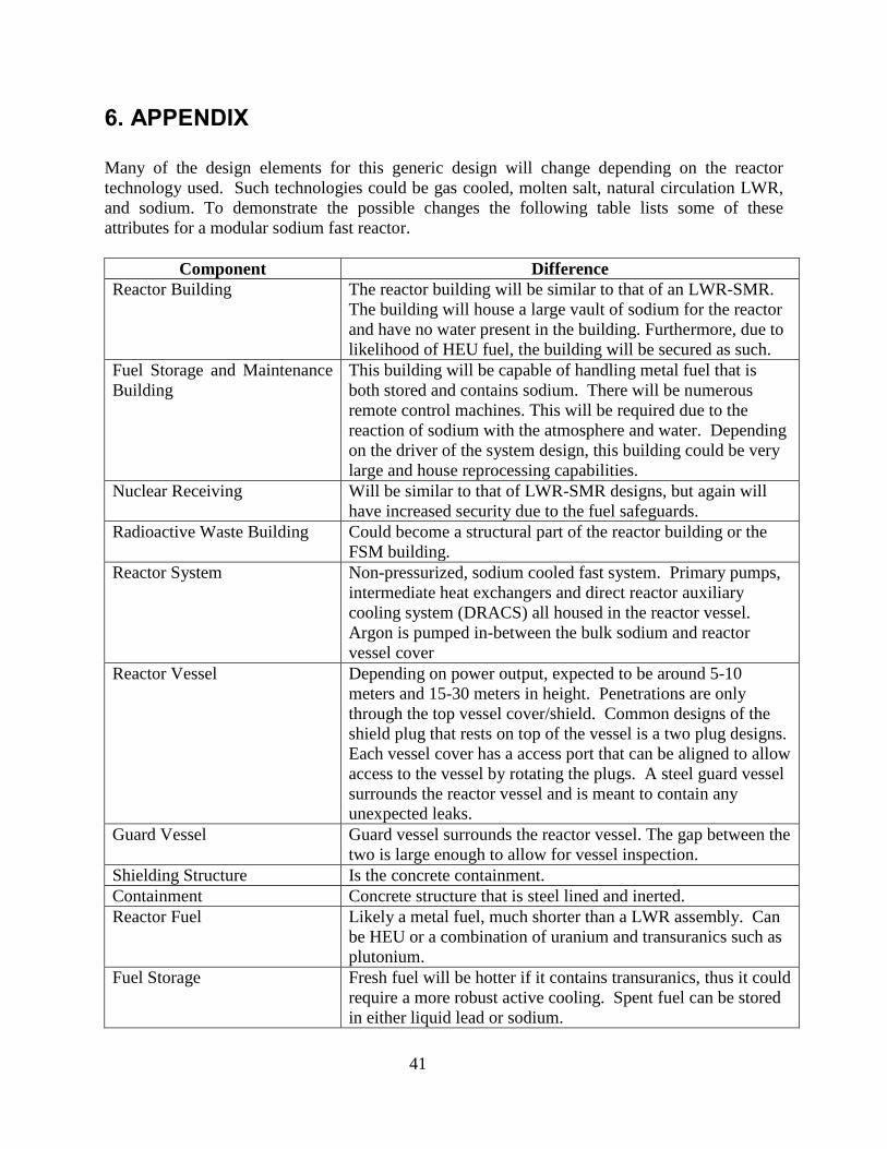
41
6. APPENDIX
Many of the design elements for this generic design will change depending on the reactor
technology used. Such technologies could be gas cooled, molten salt, natural circulation LWR,
and sodium. To demonstrate the possible changes the following table lists some of these
attributes for a modular sodium fast reactor.
Component Difference
Reactor Building The reactor building will be similar to that of an LWR-SMR.
The building will house a large vault of sodium for the reactor
and have no water present in the building. Furthermore, due to
likelihood of HEU fuel, the building will be secured as such.
Fuel Storage and Maintenance
Building
This building will be capable of handling metal fuel that is
both stored and contains sodium. There will be numerous
remote control machines. This will be required due to the
reaction of sodium with the atmosphere and water. Depending
on the driver of the system design, this building could be very
large and house reprocessing capabilities.
Nuclear Receiving Will be similar to that of LWR-SMR designs, but again will
have increased security due to the fuel safeguards.
Radioactive Waste Building Could become a structural part of the reactor building or the
FSM building.
Reactor System Non-pressurized, sodium cooled fast system. Primary pumps,
intermediate heat exchangers and direct reactor auxiliary
cooling system (DRACS) all housed in the reactor vessel.
Argon is pumped in-between the bulk sodium and reactor
vessel cover
Reactor Vessel Depending on power output, expected to be around 5-10
meters and 15-30 meters in height. Penetrations are only
through the top vessel cover/shield. Common designs of the
shield plug that rests on top of the vessel is a two plug designs.
Each vessel cover has a access port that can be aligned to allow
access to the vessel by rotating the plugs. A steel guard vessel
surrounds the reactor vessel and is meant to contain any
unexpected leaks.
Guard Vessel Guard vessel surrounds the reactor vessel. The gap between the
two is large enough to allow for vessel inspection.
Shielding Structure Is the concrete containment.
Containment Concrete structure that is steel lined and inerted.
Reactor Fuel Likely a metal fuel, much shorter than a LWR assembly. Can
be HEU or a combination of uranium and transuranics such as
plutonium.
Fuel Storage Fresh fuel will be hotter if it contains transuranics, thus it could
require a more robust active cooling. Spent fuel can be stored
in either liquid lead or sodium.
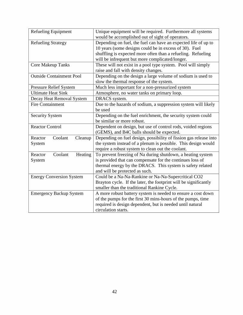
42
Refueling Equipment Unique equipment will be required. Furthermore all systems
would be accomplished out of sight of operators.
Refueling Strategy Depending on fuel, the fuel can have an expected life of up to
10 years (some designs could be in excess of 30). Fuel
shuffling is expected more often than a refueling. Refueling
will be infrequent but more complicated/longer.
Core Makeup Tanks These will not exist in a pool type system. Pool will simply
raise and fall with density changes.
Outside Containment Pool Depending on the design a large volume of sodium is used to
slow the thermal response of the system.
Pressure Relief System Much less important for a non-pressurized system
Ultimate Heat Sink Atmosphere, no water tanks on primary loop.
Decay Heat Removal System DRACS system.
Fire Containment Due to the hazards of sodium, a suppression system will likely
be used
Security System Depending on the fuel enrichment, the security system could
be similar or more robust.
Reactor Control Dependent on design, but use of control rods, voided regions
(GEMS), and B4C balls should be expected.
Reactor Coolant Cleanup
System
Depending on fuel design, possibility of fission gas release into
the system instead of a plenum is possible. This design would
require a robust system to clean out the coolant.
Reactor Coolant Heating
System
To prevent freezing of Na during shutdown, a heating system
is provided that can compensate for the continues loss of
thermal energy by the DRACS. This system is safety related
and will be protected as such.
Energy Conversion System Could be a Na-Na-Rankine or Na-Na-Supercritical CO2
Brayton cycle. If the later, the footprint will be significantly
smaller than the traditional Rankine Cycle.
Emergency Backup System A more robust battery system is needed to ensure a cost down
of the pumps for the first 30 mins-hours of the pumps, time
required is design dependent, but is needed until natural
circulation starts.

43
Related Documents