5276 JOURNAL OF LIGHTWAVE TECHNOLOGY, VOL. 27, NO. 23, DECEMBER 1, 2009 Generation of Arbitrary UWB Waveforms by Spectral Pulse Shaping and Thermally-Controlled Apodized FBGs Mohammad Abtahi, Member, IEEE, Mansour Dastmalchi, Sophie LaRochelle, Member, IEEE, Member, OSA, and Leslie A. Rusch, Senior Member, IEEE, Member, OSA Abstract—We propose and experimentally demonstrate an arbitrary UWB pulse generator. The proposed technique is based on spectral pulse shaping and frequency-to-time conversion. The reconfigurability of this technique comes from changing the apodizaton of a chirped fiber Bragg grating (FBG) using a series of heating elements (HE). By setting the appropriate temperature set to the HEs, any predesigned UWB waveforms can be generated with high precision. The effective isotropically radiated power (EIRP)-optimized and U.S. Federal Communications Commission (FCC)-optimized pulses as well as the traditional Gaussian mono- cycle and doublet UWB waveforms are generated which are in excellent match with the designed target pulse shapes. While other arbitrary pulse generators have used similar strategies (spectral shaping and frequency-to-time conversion), ours uses inexpensive technologies with the potential for practical, compact packaging. Index Terms—Fiber Bragg gratings (FBG), microwave pho- tonics, optical pulse shaping, thermally controlled apodization, ultrawideband (UWB). I. INTRODUCTION U LTRAWIDEBAND radio (UWB) is suitable for many ap- plications including wireless short-range high speed data communications, local body networks for medical sensing, mil- itary communications, precision navigation, sensor networks, surveillance and so on [1]. One of the major challenges of UWB systems is the generation of appropriate UWB pulse shapes, which has been the subject of much research in the past decade. Although the Gaussian pulse shape and its derivatives are tra- ditionally used for UWB systems, the variety of applications leads to a requirement to support a multitude of pulse shapes. A UWB pulse generator able to generate a collection of pre- designed pulse shapes would be an indispensable tool for both system designers and manufacturers. A particularly important goal for power-limited UWB systems is maximizing permis- sible transmit power under the spectral mask on the effective Manuscript received March 10, 2009; revised August 03, 2009. First pub- lished August 28, 2009; current version published October 09, 2009. This work was supported in part by TELUS Corporation and in part by the Canadian Nat- ural Science and Engineering Research Council. The authors are with the Center for Optics, Photonics and Laser (COPL), Electrical and Computer Engineering Department, Univer- sité Laval, Québec, QC G1V0A6 Canada (e-mail: [email protected]; [email protected]; [email protected]; [email protected]. ca). Color versions of one or more of the figures in this paper are available online at http://ieeexplore.ieee.org. Digital Object Identifier 10.1109/JLT.2009.2031128 isotropically radiated power (EIRP) imposed by the U.S. Fed- eral Communications Commission (FCC) for the indoor and/or outdoor applications [2]. This pulse shape varies with the an- tenna used for transmission. The minimum requirements for a UWB pulse generator are reconfigurability, simplicity, compact- ness, cost-effectiveness and compatibility with integration. The generation of UWB waveforms has been studied via vast and diversified approaches in both electronics and optics [3]–[13]. As an example of electronic UWB pulse generation consider [3], where an RF microstrip is used to generate the fourth-derivative of a Gaussian monocycle. Other pulse shapes can be fabricated in the same way, by designing the corre- sponding microstrip RF filter. Although the precision of this technique is acceptable, it does not provide tunability and needs electrical impulse generator as broadband source. Various optical techniques have been proposed to generate UWB waveforms, especially the conventional monocycle and doublets pulse shapes. The cross phase modulation (XPM) ef- fect is used in [4] to generate Gaussian monocycle and dou- blet pulses. The same pulses are generated based on XPM ef- fect in nonlinear optical loop mirror with a complex setup using three laser sources [5]. The nonlinearity of active devices like semiconductor optical amplifiers (SOAs) is exploited in [6]. In [7], the cross-polarization modulation effect is used to generate monocycle pulse and by passing this pulse through a SOA, a doublet-like waveform is obtained. The multiband UWB pulses are also generated based on hybrid photonic microwave filter. These methods have little or no reconfigurability. Recently, a polarity switchable UWB pulse generator using phase modulator and asymmetric Mach–Zehnder is proposed in [8]. The technique is simple in principle and is able to generate the monocycle and doublet pulses with both polarities. While reconfigurable, it does not support the generation of more com- plex pulse shapes. The optical UWB pulse shaping techniques provided in [9]–[13] are all based on spectral pulse shaping and fre- quency-to-time conversion using various approaches. With the exception of [11], these techniques can all be used to generate a predesigned pulse shape, but with varying difficulty and cost. Wide re-programmability is provided in [9], [10] in which any arbitrary RF waveform could be generated with high precision. The bulky pulse shaping device in [9] uses a 4- grating and lens apparatus with a spatial light modulator (SLM) to modulate the amplitude of frequency components. A similar but reflective approach is used in [10], where the SLM is replaced by a single- layer liquid crystal modulator (LCM). 0733-8724/$26.00 © 2009 IEEE Authorized licensed use limited to: BIBLIOTHEQUE DE L'UNIVERSITE LAVAL. Downloaded on June 23,2010 at 13:48:57 UTC from IEEE Xplore. Restrictions apply.

Welcome message from author
This document is posted to help you gain knowledge. Please leave a comment to let me know what you think about it! Share it to your friends and learn new things together.
Transcript
5276 JOURNAL OF LIGHTWAVE TECHNOLOGY, VOL. 27, NO. 23, DECEMBER 1, 2009
Generation of Arbitrary UWB Waveforms by SpectralPulse Shaping and Thermally-Controlled
Apodized FBGsMohammad Abtahi, Member, IEEE, Mansour Dastmalchi, Sophie LaRochelle, Member, IEEE, Member, OSA, and
Leslie A. Rusch, Senior Member, IEEE, Member, OSA
Abstract—We propose and experimentally demonstrate anarbitrary UWB pulse generator. The proposed technique is basedon spectral pulse shaping and frequency-to-time conversion.The reconfigurability of this technique comes from changing theapodizaton of a chirped fiber Bragg grating (FBG) using a seriesof heating elements (HE). By setting the appropriate temperatureset to the HEs, any predesigned UWB waveforms can be generatedwith high precision. The effective isotropically radiated power(EIRP)-optimized and U.S. Federal Communications Commission(FCC)-optimized pulses as well as the traditional Gaussian mono-cycle and doublet UWB waveforms are generated which are inexcellent match with the designed target pulse shapes. While otherarbitrary pulse generators have used similar strategies (spectralshaping and frequency-to-time conversion), ours uses inexpensivetechnologies with the potential for practical, compact packaging.
Index Terms—Fiber Bragg gratings (FBG), microwave pho-tonics, optical pulse shaping, thermally controlled apodization,ultrawideband (UWB).
I. INTRODUCTION
U LTRAWIDEBAND radio (UWB) is suitable for many ap-plications including wireless short-range high speed data
communications, local body networks for medical sensing, mil-itary communications, precision navigation, sensor networks,surveillance and so on [1]. One of the major challenges of UWBsystems is the generation of appropriate UWB pulse shapes,which has been the subject of much research in the past decade.Although the Gaussian pulse shape and its derivatives are tra-ditionally used for UWB systems, the variety of applicationsleads to a requirement to support a multitude of pulse shapes.A UWB pulse generator able to generate a collection of pre-designed pulse shapes would be an indispensable tool for bothsystem designers and manufacturers. A particularly importantgoal for power-limited UWB systems is maximizing permis-sible transmit power under the spectral mask on the effective
Manuscript received March 10, 2009; revised August 03, 2009. First pub-lished August 28, 2009; current version published October 09, 2009. This workwas supported in part by TELUS Corporation and in part by the Canadian Nat-ural Science and Engineering Research Council.
The authors are with the Center for Optics, Photonics and Laser(COPL), Electrical and Computer Engineering Department, Univer-sité Laval, Québec, QC G1V0A6 Canada (e-mail: [email protected];[email protected]; [email protected]; [email protected]).
Color versions of one or more of the figures in this paper are available onlineat http://ieeexplore.ieee.org.
Digital Object Identifier 10.1109/JLT.2009.2031128
isotropically radiated power (EIRP) imposed by the U.S. Fed-eral Communications Commission (FCC) for the indoor and/oroutdoor applications [2]. This pulse shape varies with the an-tenna used for transmission. The minimum requirements for aUWB pulse generator are reconfigurability, simplicity, compact-ness, cost-effectiveness and compatibility with integration.
The generation of UWB waveforms has been studied viavast and diversified approaches in both electronics and optics[3]–[13]. As an example of electronic UWB pulse generationconsider [3], where an RF microstrip is used to generate thefourth-derivative of a Gaussian monocycle. Other pulse shapescan be fabricated in the same way, by designing the corre-sponding microstrip RF filter. Although the precision of thistechnique is acceptable, it does not provide tunability and needselectrical impulse generator as broadband source.
Various optical techniques have been proposed to generateUWB waveforms, especially the conventional monocycle anddoublets pulse shapes. The cross phase modulation (XPM) ef-fect is used in [4] to generate Gaussian monocycle and dou-blet pulses. The same pulses are generated based on XPM ef-fect in nonlinear optical loop mirror with a complex setup usingthree laser sources [5]. The nonlinearity of active devices likesemiconductor optical amplifiers (SOAs) is exploited in [6]. In[7], the cross-polarization modulation effect is used to generatemonocycle pulse and by passing this pulse through a SOA, adoublet-like waveform is obtained. The multiband UWB pulsesare also generated based on hybrid photonic microwave filter.These methods have little or no reconfigurability.
Recently, a polarity switchable UWB pulse generator usingphase modulator and asymmetric Mach–Zehnder is proposed in[8]. The technique is simple in principle and is able to generatethe monocycle and doublet pulses with both polarities. Whilereconfigurable, it does not support the generation of more com-plex pulse shapes.
The optical UWB pulse shaping techniques provided in[9]–[13] are all based on spectral pulse shaping and fre-quency-to-time conversion using various approaches. With theexception of [11], these techniques can all be used to generatea predesigned pulse shape, but with varying difficulty and cost.
Wide re-programmability is provided in [9], [10] in which anyarbitrary RF waveform could be generated with high precision.The bulky pulse shaping device in [9] uses a 4- grating andlens apparatus with a spatial light modulator (SLM) to modulatethe amplitude of frequency components. A similar but reflectiveapproach is used in [10], where the SLM is replaced by a single-layer liquid crystal modulator (LCM).
0733-8724/$26.00 © 2009 IEEE
Authorized licensed use limited to: BIBLIOTHEQUE DE L'UNIVERSITE LAVAL. Downloaded on June 23,2010 at 13:48:57 UTC from IEEE Xplore. Restrictions apply.
ABTAHI et al.: GENERATION OF ARBITRARY UWB WAVEFORMS BY SPECTRAL PULSE SHAPING 5277
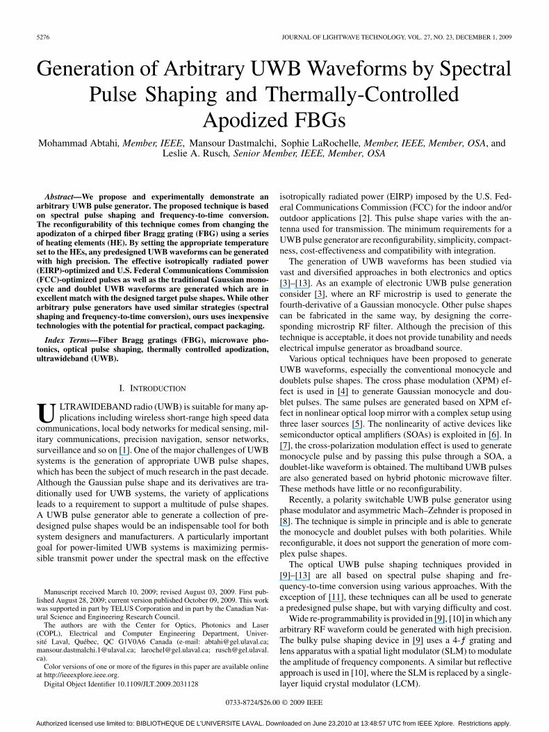
Fig. 1. Schematic diagram of the setup (MLFL: Mode-locked fiber laser; SMF: Single mode fiber; ATT: Variable attenuator; DL: Variable delay line;BPD: Balanced photodetector; FBG: Fiber Bragg grating; HE: Heating element).
In [12], we proposed and experimentally demonstrated an ef-ficient, high-precision technique for optical generation of UWBwaveforms using fiber Bragg gratings (FBG). Each UWB pulseshape required that a distinct FBG be fabricated. In [13], weproposed a technique with limited programmability that couldtune cutoff frequencies of a pair of specially designed FBGsto select the UWB pulse shape amongst Gaussian monocycle,doublet and an extremely power efficient, FCC-optimized UWBwaveform.
In this paper, we present a simple and practical techniqueto generate UWB waveforms with high precision and arbitrarycharacteristics. Waveforms are precalculated and uploaded tothe pulse generator as required. This technique is similar tothat of [10], but the technology is fiber based and not bulky.The spectral pulse shaping is performed using a FBG with tem-perature controlled apodization. A series of heating elementsare used to change locally the temperature of a uniform lin-early chirped FBG. The required spectral resolution of the pulseshaping device can be achieved by using the appropriate sizeheating elements.
The paper is organized as follows. In Section II, we de-scribe our reconfigurable pulse shaping technique. Section IIIdescribes the model applied to the temperature profile withvalidation measurements. The simulation and experimentalresults are provided in Section IV. Finally, we discuss thepractical considerations and conclusions in Section V.
II. RECONFIGURABLE UWB PULSE SHAPING
The details of our pulse shaping technique, as well as a the-oretical analysis, are provided in [12]. We use the same pulsegeneration setup, although now the FBG responsible for spec-tral pulse shaping is replaced by a reconfigurable pulse shapingdevice.
The schematic diagram of the setup is shown in Fig. 1, wherea passive mode-locked fiber laser (MLFL) is used as a coherentbroadband source. An appropriate length of SMF serves as thedispersive medium to generate the total required dispersion forthe frequency-to-time conversion. Low-pass and high-pass op-tical filters are used to cut the required spectral band of thesource. The optical signal is then divided into two arms for rea-sons to be explained shortly. The SMF may be placed anywherealong the generator; placing it before spectral shaping avoidsrequiring SMF in both arms of the BPD. The length of SMF is
chosen to map the pulse duration, , to the available sourcebandwidth, , via , where is the total fiberdispersion.
In contrast to our previous design, here we do not flatten thespectrum of the optical source; this shaping can be included inthe shaping device due to its reconfigurability. Any deviationin the generated UWB pulse due to the nonflat spectrum of theoptical source and/or any other nonuniformities can be compen-sated for in the programmable pulse shaping device.
Any pulse generated by spectral shaping is the sum of the de-sired pulse shape and a rectangular pulse with the same duration.The unwanted additive rectangular pulse superimposed on thedesired pulse shape changes the RF spectrum of the pulse at allfrequencies, with strong, unwanted spectral components at lowfrequencies ( GHz). In a brief Appendix we discuss whyhighpass filtering is not an effective solution. To remove the rect-angular pulse, we divide the optical signal in two arms, as seenin Fig. 1. Note the second arm has an optical delay line (DL) anda variable attenuator (ATT) to assure the amplitude and delay ofthe two arms are indeed balanced. The original rectangular pulseis delivered to each arm; in the upper arm it is shaped, while it re-mains unaltered in the lower arm. By subtracting the rectangularpulse in the lower arm from the strictly positive pulse-shapedsignal in the upper arm using a balanced photodetector (BPD),a positive and negative going pulse of short duration is achieved.
Our pulse shaping device consists of a fiber grating withconstant transmitivity that is placed in contact with a seriesof heating elements, as shown in the inset of Fig. 1. We useda series of Peltier thermoelectric devices as heating elements(HEs). These devices operate on the Peltier-Seebeck effect[14] and are able to provide positive or negative temperaturescompared to the ambient temperature by switching the appliedvoltage polarity. By applying the appropriate current (both inamplitude and polarity) to each HE, the apodization, and as aresult the transmitivity of the FBG can be tuned to match thedesired spectral response. The spectrally shaped pulse is sent toa dispersive medium (e.g., SMF) to perform frequency-to-timemapping.
Fig. 2 provides insight into the operation of the pulse shapingdevice. In Fig. 2(a) the band diagram at ambient temperature ofa chirped uniform FBG is shown in three dashed lines for: theBragg condition line, and the upper bandgap limit and the lowerbandgap limits. When a heating element creates a temperature
Authorized licensed use limited to: BIBLIOTHEQUE DE L'UNIVERSITE LAVAL. Downloaded on June 23,2010 at 13:48:57 UTC from IEEE Xplore. Restrictions apply.
5278 JOURNAL OF LIGHTWAVE TECHNOLOGY, VOL. 27, NO. 23, DECEMBER 1, 2009
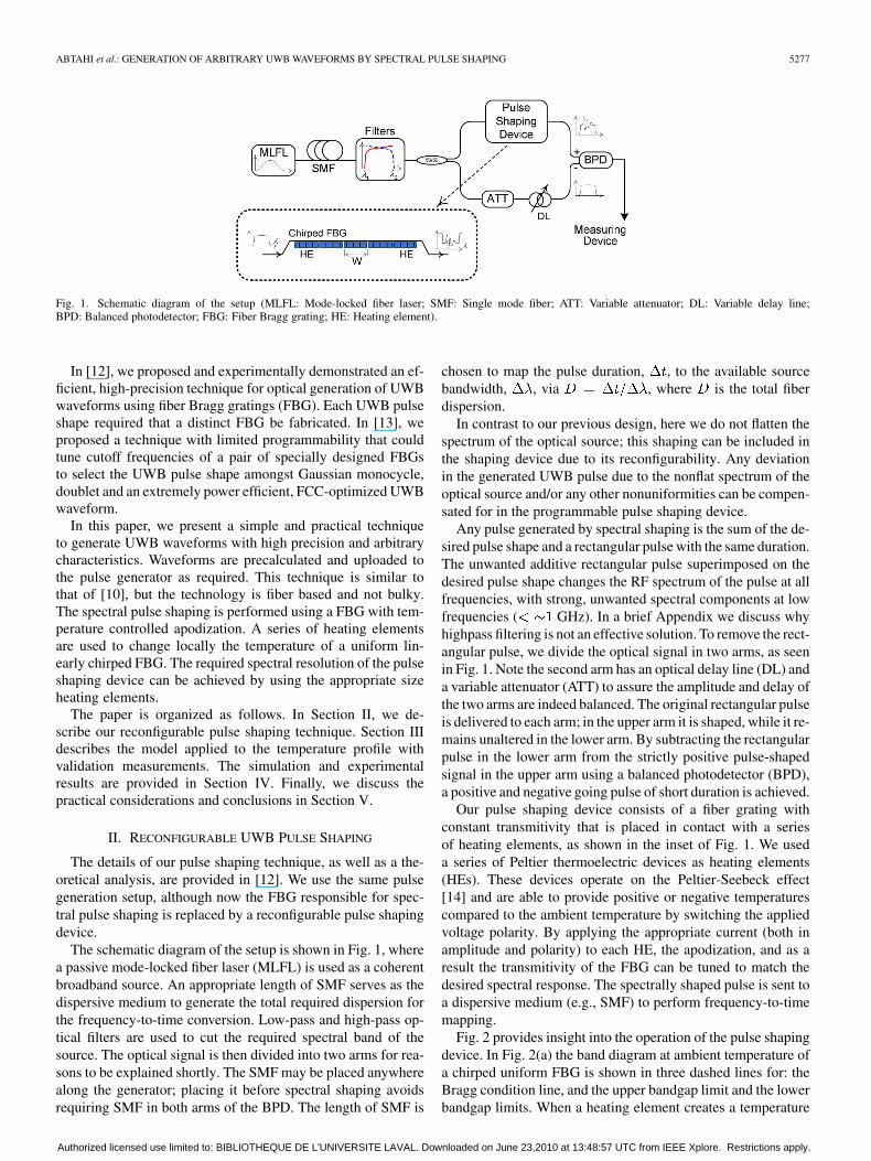
Fig. 2. Effect of a local temperature perturbation on the transmitivity of a chirped FBG (a) band diagrams, (b) a positive temperature profile, and (c) the corre-sponding changes in transmitivity.
perturbation in the fiber, this perturbation profile will modifythe local Bragg wavelength by . The temperature change
inside the fiber and are directly related by a factor ofnm/ C [15].
For instance, when a positive temperature profile with a max-imum of 20 C, as shown in Fig. 2(b), is applied to the FBG,the band diagrams change to those of the solid lines in Fig. 2(a),and as a result, the transmittivity of the chirped FBG changes asshown in Fig. 2(c). We use a simulation tool based on a transfermatrix solution of coupled-mode equations to obtain the trans-mittivity of the FBG due to temperature perturbations [16]. Theaccuracy of the simulation based on the proposed technique isgiven in [17] by comparing the simulation and experimental re-sults for various cases.
The slope and curvature of the bands determine the shapeof the variations in the transmittivity of the FBG (our opticalfilter). As the temperature perturbation is increased, the banddiagram can become strongly peaked thereby creating a reso-nant at longer wavelengths. This Fabry–Perot resonant cavity isresponsible for multiple resonant peaks in higher wavelengthsin the transfer function of the filter [17]. In the next section, wewill model the temperature profile along the fiber introduced byone heating element.
III. TEMPERATURE PROFILE
The distribution of heat along the fiber results from the com-bination of the thermo-optic and thermo-elastic effects. Heatpropagates through the fiber and the temperature profile has afull width at half maximum (FWHM) larger than the physicalsurface of the HE. A heat sink is used in our setup for the HE but
no other heat sink is used for the fiber. In this case a Lorentzianfunction models the temperature profile. When a second heatsink is placed on the fiber, the heat dissipates more readily anda Gaussian or bell shaped function would be more appropriatefor the temperature profile, depending on the size of the HE.
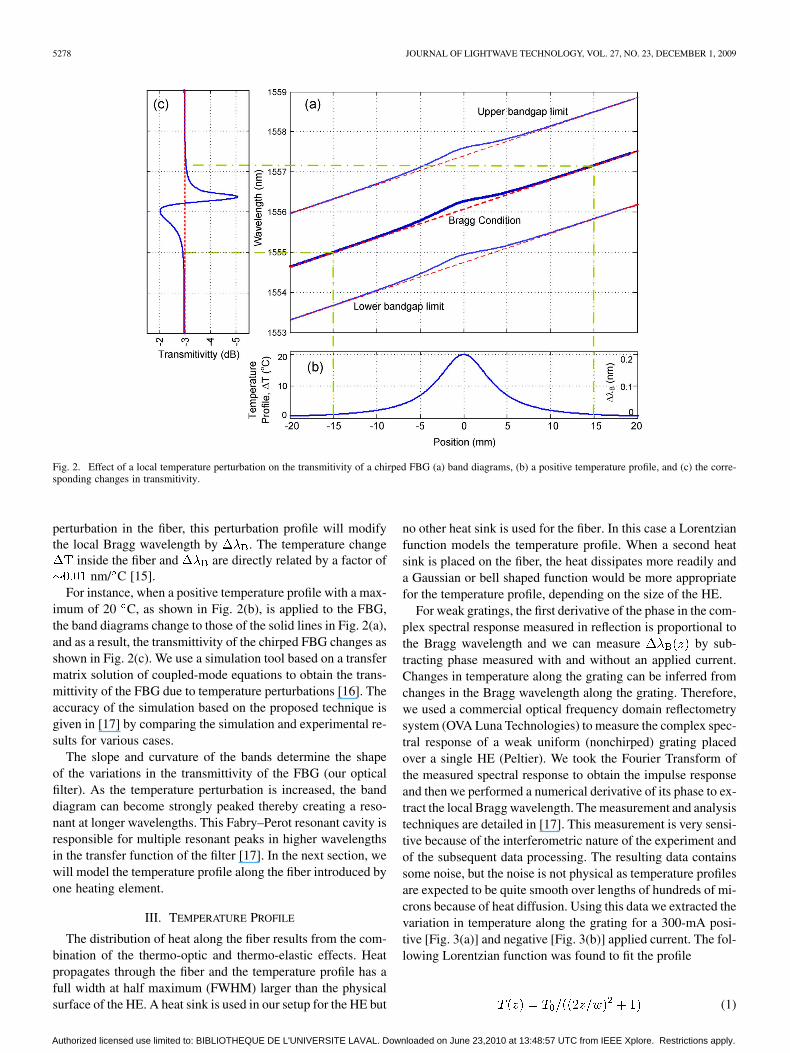
For weak gratings, the first derivative of the phase in the com-plex spectral response measured in reflection is proportional tothe Bragg wavelength and we can measure by sub-tracting phase measured with and without an applied current.Changes in temperature along the grating can be inferred fromchanges in the Bragg wavelength along the grating. Therefore,we used a commercial optical frequency domain reflectometrysystem (OVA Luna Technologies) to measure the complex spec-tral response of a weak uniform (nonchirped) grating placedover a single HE (Peltier). We took the Fourier Transform ofthe measured spectral response to obtain the impulse responseand then we performed a numerical derivative of its phase to ex-tract the local Bragg wavelength. The measurement and analysistechniques are detailed in [17]. This measurement is very sensi-tive because of the interferometric nature of the experiment andof the subsequent data processing. The resulting data containssome noise, but the noise is not physical as temperature profilesare expected to be quite smooth over lengths of hundreds of mi-crons because of heat diffusion. Using this data we extracted thevariation in temperature along the grating for a 300-mA posi-tive [Fig. 3(a)] and negative [Fig. 3(b)] applied current. The fol-lowing Lorentzian function was found to fit the profile
(1)
Authorized licensed use limited to: BIBLIOTHEQUE DE L'UNIVERSITE LAVAL. Downloaded on June 23,2010 at 13:48:57 UTC from IEEE Xplore. Restrictions apply.
ABTAHI et al.: GENERATION OF ARBITRARY UWB WAVEFORMS BY SPECTRAL PULSE SHAPING 5279
Fig. 3. Measured temperature profile for a single HE with 300 mA (a) positiveand (b) negative applied currents.
where, is the maximum temperature and represents theFWHM distance. The physical length of the HE is 4.2 mm; theFWHM exceeds this dimension and mm is used toplot the Lorentzian functions in Fig. 3 (solid lines). In [17], itis shown that the FWHM remains constant for all applied cur-rents. Therefore, we can simulate the temperature variations bychanging only the amplitude of the perturbation and not thewidth of the profile.
While identical currents were applied to the HE, a greaterswing in temperature is observed for positive current (13.5 C)versus negative current ( C). This effect is due to thetemperature distribution between two sides of the Peltier heatingelements. For a certain current (e.g., 300 mA in this case) thetemperature difference is fixed (25 C), but it is not equally di-vided between two sides. It depends on the maximum and theminimum attainable temperatures as well as the room tempera-ture. As the room temperature was about 23 C, the 300 mAapplied current has increased the temperature of one side by13.5 C and decreased the temperature of other side by 11.5 Cinstead of changing both side by 12.5 C. In this paper, we ex-press control signals in terms of temperature excursion insteadof applied current.
IV. SIMULATION AND EXPERIMENTAL RESULTS
We sought a temperature profile to achieve a target UWBwaveform. For simulation purposes, we construct the temper-ature profile from a sum of Lorentzian functions for each HE.Using a given temperature set, we then model the grating spec-tral response using the transfer matrix simulation as describedin the previous section.
The optimum temperature profile is found via a genetic algo-rithm [18] minimizing the total error between target waveformand simulation. The algorithm considers 130 generations and apopulation size of 20. The initial temperature is random, andthe algorithm continues until the total error goes below a cer-tain threshold. An optimization required about 30 hours usinga 3 GHz Pentium 4 processor. Hence, profiles cannot be calcu-late on the fly, but rather temperature profiles for various UWBwaveforms should be precalculated and saved to memory forfast recovery.
Although we have found that the calculated temperature setprovides a good estimate of the required setting of the HE, somefinal adjustment was necessary in the experiment to optimizethe profile. This is not surprising considering that heat diffu-sion occurs along the fiber and that the HE are closely spaced.Complete heat diffusion modeling could be included in the op-timization procedure to achieve a more accurate prediction.
The ability to easily tune the pulse shaping FBG gives greatflexibility to experimenter or manufacturer. For instance, anynonuniformity in the optical source spectrum can be easily com-pensated by adjusting the target waveform. The imperfections inthe writing of the uniform chirped FBG in the pulse shaping de-vice (Fig. 1) can be also treated in the same manner. We definean error waveform as the output of the BPD when no current isapplied to the HEs. This waveform contains all imperfectionsincluding the effect of nonflat spectrum and other imperfectionsduring the fabrication process of the chirped FBG. For a man-ufacturer, tunability also allows for pulse shapes to be easilymodified as new components, such as antennas, are introduced.
The chirp of the FBG determines the resolution of the pulseshaping in the time domain. The FBG is written with chirp of0.498 nm/cm and constant transmittivity ( dB). A length,4.2-mm HE leads to a linewidth of nm. To transform thisinto time resolution, recall that 5.46 km of SMF gives 89 ps/nmof dispersion. Therefore, each HE covers almost 27 ps of thetime domain pulse. However, it should be noted that the HE im-pact is not limited to its physical length; in particular, when thetemperature difference between adjacent HEs is high, an oscil-latory effect in FBG transmittivity can be observed.
The FCC spectral mask constrains the effective isotropicallyradiated power (EIRP) of the antenna rather than power spectraldensity (PSD) of pulses before transmission. We first start withan EIRP optimized waveform which we designed [19] to max-imize the permissible EIRP including the effect of the poweramplifier and the SkyCross antenna used in our experiments.We demonstrated that the transmit power for this waveform wasmore than 11 dB higher than the Gaussian monocycle wave-form, without violating FCC regulations.
Authorized licensed use limited to: BIBLIOTHEQUE DE L'UNIVERSITE LAVAL. Downloaded on June 23,2010 at 13:48:57 UTC from IEEE Xplore. Restrictions apply.
5280 JOURNAL OF LIGHTWAVE TECHNOLOGY, VOL. 27, NO. 23, DECEMBER 1, 2009
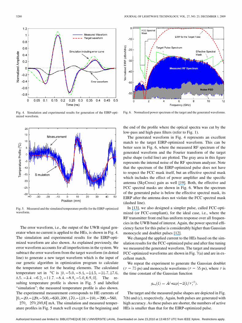
Fig. 4. Simulation and experimental results for generation of the EIRP-opti-mized waveform.
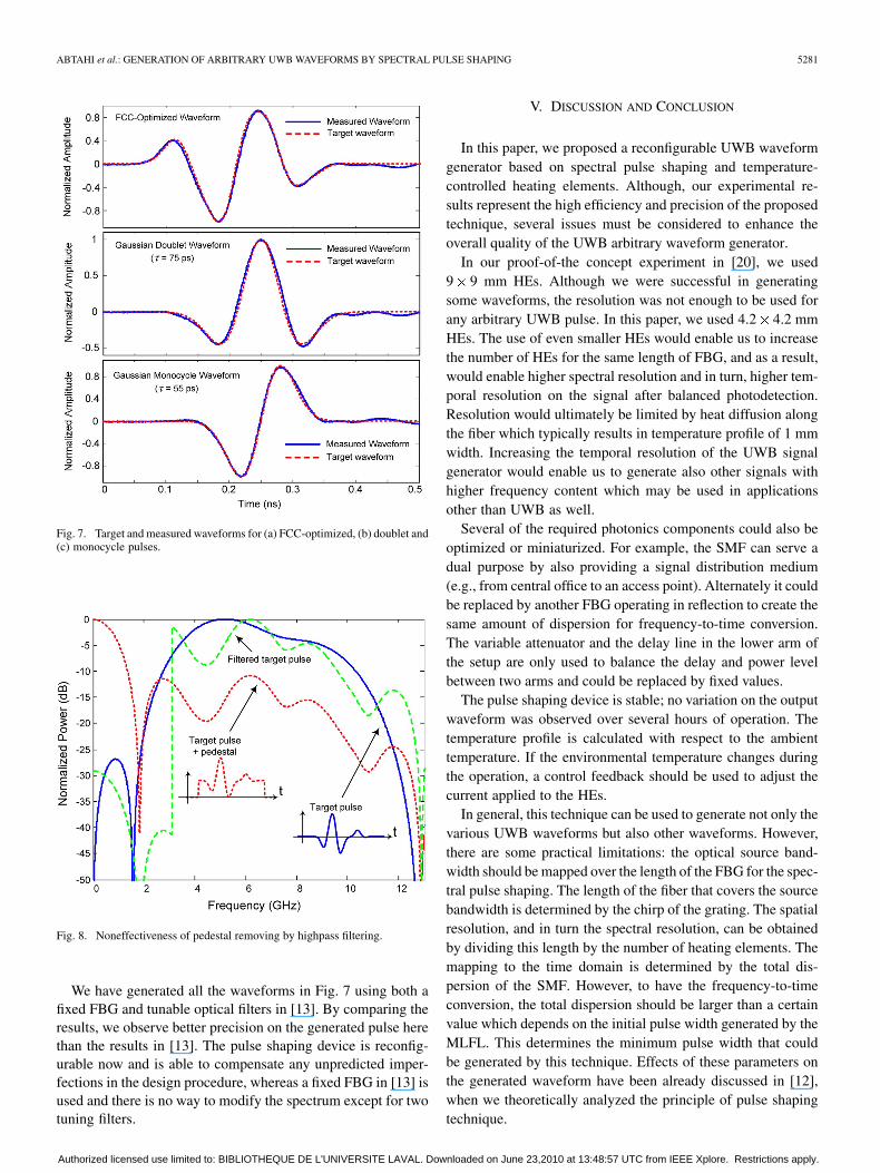
Fig. 5. Measured and the simulated temperature profile for the EIRP-optimizedwaveform.
The error waveform, i.e., the output of the UWB signal gen-erator when no current is applied to the HEs, is shown in Fig. 4.The simulation and experimental results for the EIRP-opti-mized waveform are also shown. As explained previously, theerror waveform accounts for all imperfections in the system. Wesubtract the error waveform from the target waveform (in dottedline) to generate a new target waveform which is the input ofour genetic algorithm in optimization program to calculatethe temperature set for the heating elements. The calculatedtemperature set in C is
. The re-sulting temperature profile is shown in Fig. 5 and labelled“simulation”; the measured temperature profile is also shown.The experimental measurement corresponds to HE currents of
mA. The simulation and measured temper-ature profiles in Fig. 5 match well except for the beginning and
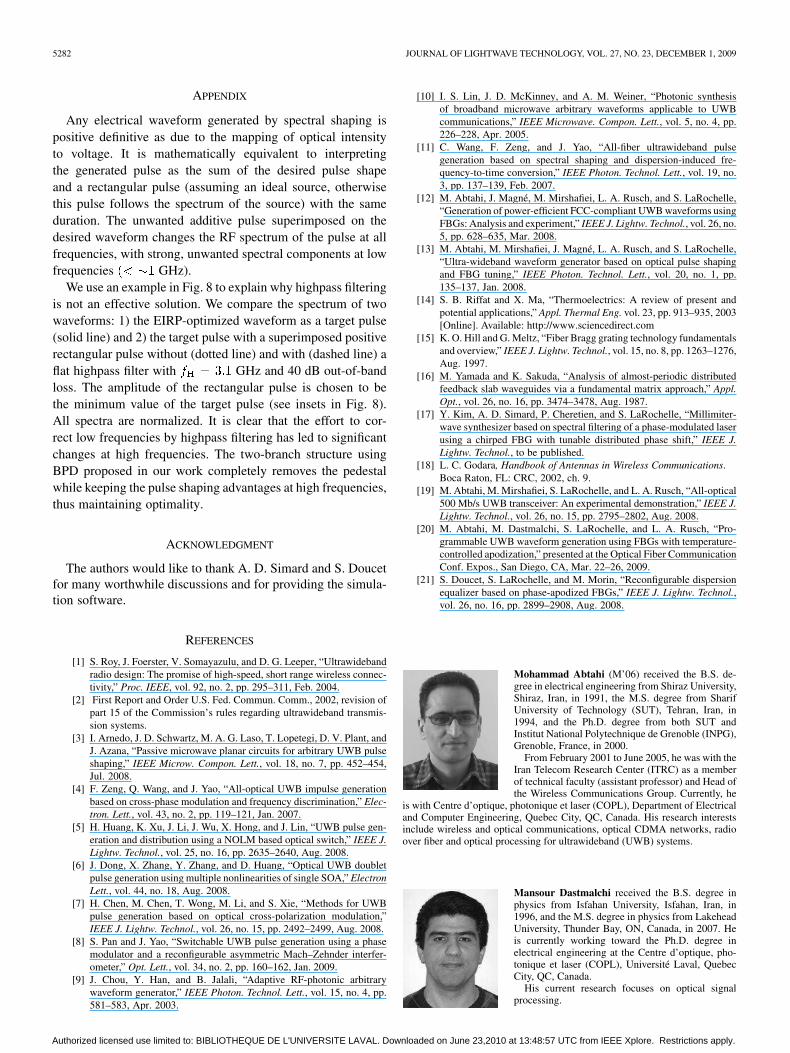
Fig. 6. Normalized power spectrum of the target and the generated waveforms.
the end of the profile where the optical spectra was cut by thelow-pass and high-pass filters (refer to Fig. 1).
The generated waveform in Fig. 4 represents an excellentmatch to the target EIRP-optimized waveform. This can bebetter seen in Fig. 6, where the measured RF spectrum of thegenerated waveform and the Fourier transform of the targetpulse shape (solid line) are plotted. The gray area in this figurerepresents the internal noise of the RF spectrum analyzer. Notethat the spectrum of the EIRP-optimized pulse does not haveto respect the FCC mask itself, but an effective spectral maskwhich includes the effect of power amplifier and the specificantenna (SkyCross) gain as well [19]. Both, the effective andFCC spectral masks are shown in Fig. 6. When the spectrumof the generated pulse is below the effective spectral mask, itsEIRP after the antenna does not violate the FCC spectral mask(dashed line).
In [13], we also designed a simpler pulse, called FCC-opti-mized (or FCC-compliant), for the ideal case, i.e., where theRF transmitter front end has uniform response over all frequen-cies in the UWB band of interest. Again, the power spectral effi-ciency factor for this pulse is considerably higher than Gaussianmonocycle and doublet pulses [12].
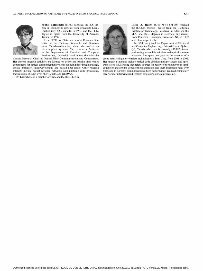
We changed the applied current to the HEs based on the sim-ulation results for the FCC-optimized pulse and after fine tuningwe measured the generated waveform. The target and measuredFCC-optimized waveforms are shown in Fig. 7(a) and are in ex-cellent match.
We repeat the experiment to generate the Gaussian doublet( ps) and monocycle waveforms ( ps), where isthe time constant of the Gaussian function
The target and the measured pulse shapes are depicted in Fig.7(b) and (c), respectively. Again, both pulses are generated withhigh accuracy. As these pulses are shorter, the numbers of activeHEs is smaller than that for the EIRP-optimized pulse.
Authorized licensed use limited to: BIBLIOTHEQUE DE L'UNIVERSITE LAVAL. Downloaded on June 23,2010 at 13:48:57 UTC from IEEE Xplore. Restrictions apply.
ABTAHI et al.: GENERATION OF ARBITRARY UWB WAVEFORMS BY SPECTRAL PULSE SHAPING 5281
Fig. 7. Target and measured waveforms for (a) FCC-optimized, (b) doublet and(c) monocycle pulses.
Fig. 8. Noneffectiveness of pedestal removing by highpass filtering.
We have generated all the waveforms in Fig. 7 using both afixed FBG and tunable optical filters in [13]. By comparing theresults, we observe better precision on the generated pulse herethan the results in [13]. The pulse shaping device is reconfig-urable now and is able to compensate any unpredicted imper-fections in the design procedure, whereas a fixed FBG in [13] isused and there is no way to modify the spectrum except for twotuning filters.
V. DISCUSSION AND CONCLUSION
In this paper, we proposed a reconfigurable UWB waveformgenerator based on spectral pulse shaping and temperature-controlled heating elements. Although, our experimental re-sults represent the high efficiency and precision of the proposedtechnique, several issues must be considered to enhance theoverall quality of the UWB arbitrary waveform generator.
In our proof-of-the concept experiment in [20], we used9 9 mm HEs. Although we were successful in generatingsome waveforms, the resolution was not enough to be used forany arbitrary UWB pulse. In this paper, we used 4.2 4.2 mmHEs. The use of even smaller HEs would enable us to increasethe number of HEs for the same length of FBG, and as a result,would enable higher spectral resolution and in turn, higher tem-poral resolution on the signal after balanced photodetection.Resolution would ultimately be limited by heat diffusion alongthe fiber which typically results in temperature profile of 1 mmwidth. Increasing the temporal resolution of the UWB signalgenerator would enable us to generate also other signals withhigher frequency content which may be used in applicationsother than UWB as well.
Several of the required photonics components could also beoptimized or miniaturized. For example, the SMF can serve adual purpose by also providing a signal distribution medium(e.g., from central office to an access point). Alternately it couldbe replaced by another FBG operating in reflection to create thesame amount of dispersion for frequency-to-time conversion.The variable attenuator and the delay line in the lower arm ofthe setup are only used to balance the delay and power levelbetween two arms and could be replaced by fixed values.
The pulse shaping device is stable; no variation on the outputwaveform was observed over several hours of operation. Thetemperature profile is calculated with respect to the ambienttemperature. If the environmental temperature changes duringthe operation, a control feedback should be used to adjust thecurrent applied to the HEs.
In general, this technique can be used to generate not only thevarious UWB waveforms but also other waveforms. However,there are some practical limitations: the optical source band-width should be mapped over the length of the FBG for the spec-tral pulse shaping. The length of the fiber that covers the sourcebandwidth is determined by the chirp of the grating. The spatialresolution, and in turn the spectral resolution, can be obtainedby dividing this length by the number of heating elements. Themapping to the time domain is determined by the total dis-persion of the SMF. However, to have the frequency-to-timeconversion, the total dispersion should be larger than a certainvalue which depends on the initial pulse width generated by theMLFL. This determines the minimum pulse width that couldbe generated by this technique. Effects of these parameters onthe generated waveform have been already discussed in [12],when we theoretically analyzed the principle of pulse shapingtechnique.
Authorized licensed use limited to: BIBLIOTHEQUE DE L'UNIVERSITE LAVAL. Downloaded on June 23,2010 at 13:48:57 UTC from IEEE Xplore. Restrictions apply.
5282 JOURNAL OF LIGHTWAVE TECHNOLOGY, VOL. 27, NO. 23, DECEMBER 1, 2009
APPENDIX
Any electrical waveform generated by spectral shaping ispositive definitive as due to the mapping of optical intensityto voltage. It is mathematically equivalent to interpretingthe generated pulse as the sum of the desired pulse shapeand a rectangular pulse (assuming an ideal source, otherwisethis pulse follows the spectrum of the source) with the sameduration. The unwanted additive pulse superimposed on thedesired waveform changes the RF spectrum of the pulse at allfrequencies, with strong, unwanted spectral components at lowfrequencies GHz).
We use an example in Fig. 8 to explain why highpass filteringis not an effective solution. We compare the spectrum of twowaveforms: 1) the EIRP-optimized waveform as a target pulse(solid line) and 2) the target pulse with a superimposed positiverectangular pulse without (dotted line) and with (dashed line) aflat highpass filter with GHz and 40 dB out-of-bandloss. The amplitude of the rectangular pulse is chosen to bethe minimum value of the target pulse (see insets in Fig. 8).All spectra are normalized. It is clear that the effort to cor-rect low frequencies by highpass filtering has led to significantchanges at high frequencies. The two-branch structure usingBPD proposed in our work completely removes the pedestalwhile keeping the pulse shaping advantages at high frequencies,thus maintaining optimality.
ACKNOWLEDGMENT
The authors would like to thank A. D. Simard and S. Doucetfor many worthwhile discussions and for providing the simula-tion software.
REFERENCES
[1] S. Roy, J. Foerster, V. Somayazulu, and D. G. Leeper, “Ultrawidebandradio design: The promise of high-speed, short range wireless connec-tivity,” Proc. IEEE, vol. 92, no. 2, pp. 295–311, Feb. 2004.
[2] First Report and Order U.S. Fed. Commun. Comm., 2002, revision ofpart 15 of the Commission’s rules regarding ultrawideband transmis-sion systems.
[3] I. Arnedo, J. D. Schwartz, M. A. G. Laso, T. Lopetegi, D. V. Plant, andJ. Azana, “Passive microwave planar circuits for arbitrary UWB pulseshaping,” IEEE Microw. Compon. Lett., vol. 18, no. 7, pp. 452–454,Jul. 2008.
[4] F. Zeng, Q. Wang, and J. Yao, “All-optical UWB impulse generationbased on cross-phase modulation and frequency discrimination,” Elec-tron. Lett., vol. 43, no. 2, pp. 119–121, Jan. 2007.
[5] H. Huang, K. Xu, J. Li, J. Wu, X. Hong, and J. Lin, “UWB pulse gen-eration and distribution using a NOLM based optical switch,” IEEE J.Lightw. Technol., vol. 25, no. 16, pp. 2635–2640, Aug. 2008.
[6] J. Dong, X. Zhang, Y. Zhang, and D. Huang, “Optical UWB doubletpulse generation using multiple nonlinearities of single SOA,” ElectronLett., vol. 44, no. 18, Aug. 2008.
[7] H. Chen, M. Chen, T. Wong, M. Li, and S. Xie, “Methods for UWBpulse generation based on optical cross-polarization modulation,”IEEE J. Lightw. Technol., vol. 26, no. 15, pp. 2492–2499, Aug. 2008.
[8] S. Pan and J. Yao, “Switchable UWB pulse generation using a phasemodulator and a reconfigurable asymmetric Mach–Zehnder interfer-ometer,” Opt. Lett., vol. 34, no. 2, pp. 160–162, Jan. 2009.
[9] J. Chou, Y. Han, and B. Jalali, “Adaptive RF-photonic arbitrarywaveform generator,” IEEE Photon. Technol. Lett., vol. 15, no. 4, pp.581–583, Apr. 2003.
[10] I. S. Lin, J. D. McKinney, and A. M. Weiner, “Photonic synthesisof broadband microwave arbitrary waveforms applicable to UWBcommunications,” IEEE Microwave. Compon. Lett., vol. 5, no. 4, pp.226–228, Apr. 2005.
[11] C. Wang, F. Zeng, and J. Yao, “All-fiber ultrawideband pulsegeneration based on spectral shaping and dispersion-induced fre-quency-to-time conversion,” IEEE Photon. Technol. Lett., vol. 19, no.3, pp. 137–139, Feb. 2007.
[12] M. Abtahi, J. Magné, M. Mirshafiei, L. A. Rusch, and S. LaRochelle,“Generation of power-efficient FCC-compliant UWB waveforms usingFBGs: Analysis and experiment,” IEEE J. Lightw. Technol., vol. 26, no.5, pp. 628–635, Mar. 2008.
[13] M. Abtahi, M. Mirshafiei, J. Magné, L. A. Rusch, and S. LaRochelle,“Ultra-wideband waveform generator based on optical pulse shapingand FBG tuning,” IEEE Photon. Technol. Lett., vol. 20, no. 1, pp.135–137, Jan. 2008.
[14] S. B. Riffat and X. Ma, “Thermoelectrics: A review of present andpotential applications,” Appl. Thermal Eng. vol. 23, pp. 913–935, 2003[Online]. Available: http://www.sciencedirect.com
[15] K. O. Hill and G. Meltz, “Fiber Bragg grating technology fundamentalsand overview,” IEEE J. Lightw. Technol., vol. 15, no. 8, pp. 1263–1276,Aug. 1997.
[16] M. Yamada and K. Sakuda, “Analysis of almost-periodic distributedfeedback slab waveguides via a fundamental matrix approach,” Appl.Opt., vol. 26, no. 16, pp. 3474–3478, Aug. 1987.
[17] Y. Kim, A. D. Simard, P. Cheretien, and S. LaRochelle, “Millimiter-wave synthesizer based on spectral filtering of a phase-modulated laserusing a chirped FBG with tunable distributed phase shift,” IEEE J.Lightw. Technol., to be published.
[18] L. C. Godara, Handbook of Antennas in Wireless Communications.Boca Raton, FL: CRC, 2002, ch. 9.
[19] M. Abtahi, M. Mirshafiei, S. LaRochelle, and L. A. Rusch, “All-optical500 Mb/s UWB transceiver: An experimental demonstration,” IEEE J.Lightw. Technol., vol. 26, no. 15, pp. 2795–2802, Aug. 2008.
[20] M. Abtahi, M. Dastmalchi, S. LaRochelle, and L. A. Rusch, “Pro-grammable UWB waveform generation using FBGs with temperature-controlled apodization,” presented at the Optical Fiber CommunicationConf. Expos., San Diego, CA, Mar. 22–26, 2009.
[21] S. Doucet, S. LaRochelle, and M. Morin, “Reconfigurable dispersionequalizer based on phase-apodized FBGs,” IEEE J. Lightw. Technol.,vol. 26, no. 16, pp. 2899–2908, Aug. 2008.
Mohammad Abtahi (M’06) received the B.S. de-gree in electrical engineering from Shiraz University,Shiraz, Iran, in 1991, the M.S. degree from SharifUniversity of Technology (SUT), Tehran, Iran, in1994, and the Ph.D. degree from both SUT andInstitut National Polytechnique de Grenoble (INPG),Grenoble, France, in 2000.
From February 2001 to June 2005, he was with theIran Telecom Research Center (ITRC) as a memberof technical faculty (assistant professor) and Head ofthe Wireless Communications Group. Currently, he
is with Centre d’optique, photonique et laser (COPL), Department of Electricaland Computer Engineering, Quebec City, QC, Canada. His research interestsinclude wireless and optical communications, optical CDMA networks, radioover fiber and optical processing for ultrawideband (UWB) systems.
Mansour Dastmalchi received the B.S. degree inphysics from Isfahan University, Isfahan, Iran, in1996, and the M.S. degree in physics from LakeheadUniversity, Thunder Bay, ON, Canada, in 2007. Heis currently working toward the Ph.D. degree inelectrical engineering at the Centre d’optique, pho-tonique et laser (COPL), Université Laval, QuebecCity, QC, Canada.
His current research focuses on optical signalprocessing.
Authorized licensed use limited to: BIBLIOTHEQUE DE L'UNIVERSITE LAVAL. Downloaded on June 23,2010 at 13:48:57 UTC from IEEE Xplore. Restrictions apply.
ABTAHI et al.: GENERATION OF ARBITRARY UWB WAVEFORMS BY SPECTRAL PULSE SHAPING 5283
Sophie LaRochelle (M’00) received the B.S. de-gree in engineering physics from Université Laval,Quebec City, QC, Canada, in 1987, and the Ph.D.degree in optics from the University of Arizona,Tucson, in 1992.
From 1992 to 1996, she was a Research Sci-entist at the Defense Research and Develop-ment Canada—Valcartier, where she worked onelectro-optical systems. She is now a Professorin the Department of Electrical and ComputerEngineering, Université Laval, where she holds the
Canada Research Chair in Optical Fibre Communications and Components.Her current research activities are focused on active and passive fiber opticscomponents for optical communication systems including fiber Bragg gratings,optical amplifiers, multiwavelength, and pulsed fiber lasers. Other researchinterests include packet-switched networks with photonic code processing,transmission of radio-over-fiber signals, and OCDMA.
Dr. LaRochelle is a member of OSA and the IEEE-LEOS.
Leslie A. Rusch (S’91–M’94–SM’00) receivedthe B.S.E.E. (honors) degree from the CaliforniaInstitute of Technology, Pasadena, in 1980, and theM.A. and Ph.D. degrees in electrical engineeringfrom Princeton University, Princeton, NJ, in 1992and 1994, respectively.
In 1994, she joined the Department of Electricaland Computer Engineering, Universit Laval, Qubec,QC, Canada, where she is currently a Full Professorperforming research in wireless and optical commu-nications. She spent two years as the manager of a
group researching new wireless technologies at Intel Corp. from 2001 to 2002.Her research interests include optical-code-division multiple access and spec-trum sliced WDM using incoherent sources for passive optical networks; semi-conductor and erbium-doped optical amplifiers and their dynamics; radio overfiber; and in wireless communications, high performance, reduced complexityreceivers for ultrawideband systems employing optical processing.
Authorized licensed use limited to: BIBLIOTHEQUE DE L'UNIVERSITE LAVAL. Downloaded on June 23,2010 at 13:48:57 UTC from IEEE Xplore. Restrictions apply.
Related Documents