GENERAL SPECIFICATION FOR AIR-CONDITIONING, REFRIGERATION, VENTILATION AND CENTRAL MONITORING & CONTROL SYSTEM INSTALLATION IN GOVERNMENT BUILDINGS OF THE HONG KONG SPECIAL ADMINISTRATIVE REGION 2001 EDITION (VOLUME II) © THE HONG KONG SPECIAL ADMINISTRATIVE REGION BUILDING SERVICES BRANCH ARCHITECTURAL SERVICES DEPARTMENT

Welcome message from author
This document is posted to help you gain knowledge. Please leave a comment to let me know what you think about it! Share it to your friends and learn new things together.
Transcript
GENERAL SPECIFICATION
FOR
AIR-CONDITIONING, REFRIGERATION, VENTILATION
AND
CENTRAL MONITORING & CONTROL SYSTEM
INSTALLATION
IN
GOVERNMENT BUILDINGS
OF
THE HONG KONG SPECIAL ADMINISTRATIVE REGION
2001 EDITION
(VOLUME II)
© THE HONG KONG SPECIAL ADMINISTRATIVE REGION
BUILDING SERVICES BRANCHARCHITECTURAL SERVICES DEPARTMENT
COPYRIGHT
This General Specification for Air-conditioning, Refrigeration, Ventilation andCentral Monitoring and Control System Installation is copyrighted and all rights(including subsequent amendments) are reserved.
2. This General Specification is solely compiled for use on Air-conditioning,Refrigeration, Ventilation and Central Monitoring and Control System installations inGovernment buildings of the Hong Kong Special Administrative Region.
3. It is hereby declared that the specification contained herein may not be pertinent orfully cover the extent of installations carried out by others. Prior consent by the Directorof Architectural Services must be obtained for adoption of this General Specification oninstallations of other nature or locations.
Section C1
SECTION C1
AIR CLEANING EQUIPMENT
C1.1 GENERAL
Filters shall have the specified performance and fire property in accordance with thetest methods of one of the standards stated in Sub-section C1.2.
To improve indoor air quality and protect air conditioning equipment, outdoor airand re-circulated indoor air shall be filtered to remove dust, bacteria, pollens,insects, soot and dirt particles before it enters the air conditioning system. Thefollowing air cleaning devices, dependent on their compatibility with the general airconditioning system, shall be incorporated into the system as in-duct devices or bestand-alone devices.
C1.1.1 Particulate Filter
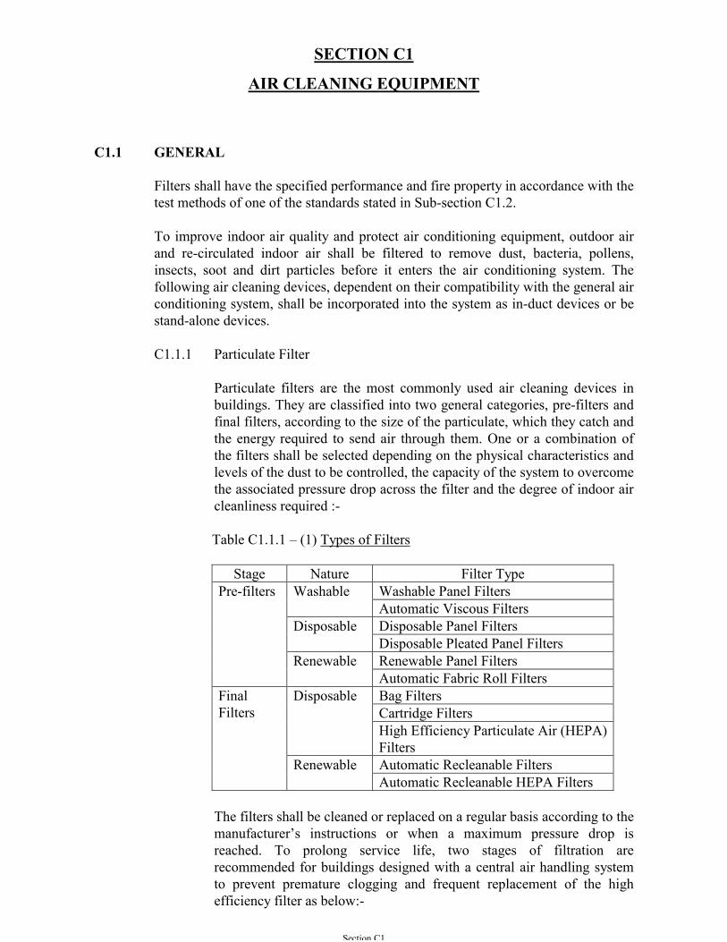
Particulate filters are the most commonly used air cleaning devices inbuildings. They are classified into two general categories, pre-filters andfinal filters, according to the size of the particulate, which they catch andthe energy required to send air through them. One or a combination ofthe filters shall be selected depending on the physical characteristics andlevels of the dust to be controlled, the capacity of the system to overcomethe associated pressure drop across the filter and the degree of indoor aircleanliness required :-
Table C1.1.1 – (1) Types of Filters
Stage Nature Filter TypeWashable Panel FiltersWashableAutomatic Viscous FiltersDisposable Panel FiltersDisposableDisposable Pleated Panel FiltersRenewable Panel Filters
Pre-filters
RenewableAutomatic Fabric Roll Filters
Disposable Bag FiltersCartridge FiltersHigh Efficiency Particulate Air (HEPA)Filters
Renewable Automatic Recleanable Filters
FinalFilters
Automatic Recleanable HEPA Filters
The filters shall be cleaned or replaced on a regular basis according to themanufacturer’s instructions or when a maximum pressure drop isreached. To prolong service life, two stages of filtration arerecommended for buildings designed with a central air handling systemto prevent premature clogging and frequent replacement of the highefficiency filter as below:-
Section C1
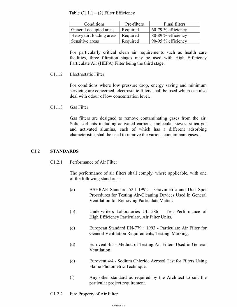
Table C1.1.1 – (2) Filter Efficiency
Conditions Pre-filters Final filtersGeneral occupied areas Required 60-79 % efficiencyHeavy dirt loading areas Required 80-89 % efficiencySensitive areas Required 90-95 % efficiency
For particularly critical clean air requirements such as health carefacilities, three filtration stages may be used with High EfficiencyParticulate Air (HEPA) Filter being the third stage.
C1.1.2 Electrostatic Filter
For conditions where low pressure drop, energy saving and minimumservicing are concerned, electrostatic filters shall be used which can alsodeal with odour of low concentration level.
C1.1.3 Gas Filter
Gas filters are designed to remove contaminating gases from the air.Solid sorbents including activated carbons, molecular sieves, silica geland activated alumina, each of which has a different adsorbingcharacteristic, shall be used to remove the various contaminant gases.
C1.2 STANDARDS
C1.2.1 Performance of Air Filter
The performance of air filters shall comply, where applicable, with oneof the following standards :-
(a) ASHRAE Standard 52.1-1992 – Gravimetric and Dust-SpotProcedures for Testing Air-Cleaning Devices Used in GeneralVentilation for Removing Particulate Matter.
(b) Underwriters Laboratories UL 586 – Test Performance ofHigh Efficiency Particulate, Air Filter Units.
(c) European Standard EN-779 : 1993 - Particulate Air Filter forGeneral Ventilation Requirements, Testing, Marking.
(d) Eurovent 4/5 - Method of Testing Air Filters Used in GeneralVentilation.
(e) Eurovent 4/4 - Sodium Chloride Aerosol Test for Filters UsingFlame Photometric Technique.
(f) Any other standard as required by the Architect to suit theparticular project requirement.
C1.2.2 Fire Property of Air Filter
Section C1
The fire property of air filters and its associated accessories shall complywith one of the following standards as well as the latest requirement ofFire Services Department:
(a) British Standard Institution BS 476 : Part 4 - Non-Combustibility Test for Materials.
(b) British Standard Institution BS 476 : Part 6 - Method of Testfor Fire Propagation for Products, with Indices "I" ≤ 12 and"i1" ≤ 6.
(c) Underwriters Laboratories UL 900 - Standard for Air FilterUnits, Class 1 or Class 2.
(d) European Standard DIN 53 438 Part 3 - Response to Ignitionby A Small Flame, Surface Ignition, Class F1.
C1.3 DRY REPLACEABLE MEDIUM TYPE FILTER
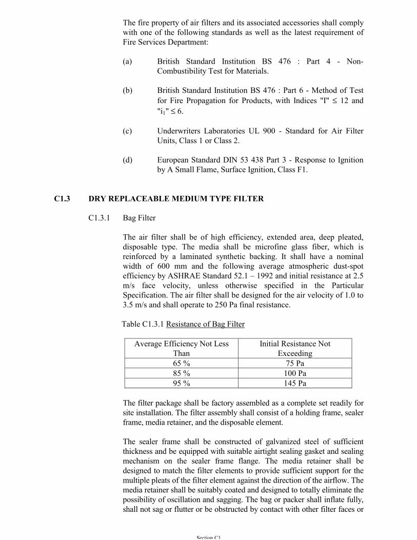
C1.3.1 Bag Filter
The air filter shall be of high efficiency, extended area, deep pleated,disposable type. The media shall be microfine glass fiber, which isreinforced by a laminated synthetic backing. It shall have a nominalwidth of 600 mm and the following average atmospheric dust-spotefficiency by ASHRAE Standard 52.1 – 1992 and initial resistance at 2.5m/s face velocity, unless otherwise specified in the ParticularSpecification. The air filter shall be designed for the air velocity of 1.0 to3.5 m/s and shall operate to 250 Pa final resistance.
Table C1.3.1 Resistance of Bag Filter
Average Efficiency Not LessThan
Initial Resistance NotExceeding
65 % 75 Pa85 % 100 Pa95 % 145 Pa
The filter package shall be factory assembled as a complete set readily forsite installation. The filter assembly shall consist of a holding frame, sealerframe, media retainer, and the disposable element.
The sealer frame shall be constructed of galvanized steel of sufficientthickness and be equipped with suitable airtight sealing gasket and sealingmechanism on the sealer frame flange. The media retainer shall bedesigned to match the filter elements to provide sufficient support for themultiple pleats of the filter element against the direction of the airflow. Themedia retainer shall be suitably coated and designed to totally eliminate thepossibility of oscillation and sagging. The bag or packer shall inflate fully,shall not sag or flutter or be obstructed by contact with other filter faces or
Section C1
ductwork surfaces when operation between 60 - 110% of design airvolume flow rate for fixed volume system.
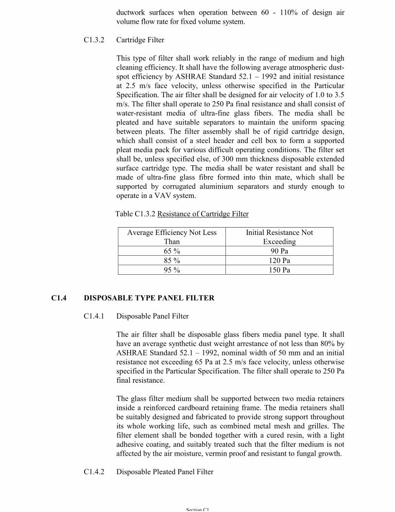
C1.3.2 Cartridge Filter
This type of filter shall work reliably in the range of medium and highcleaning efficiency. It shall have the following average atmospheric dust-spot efficiency by ASHRAE Standard 52.1 – 1992 and initial resistanceat 2.5 m/s face velocity, unless otherwise specified in the ParticularSpecification. The air filter shall be designed for air velocity of 1.0 to 3.5m/s. The filter shall operate to 250 Pa final resistance and shall consist ofwater-resistant media of ultra-fine glass fibers. The media shall bepleated and have suitable separators to maintain the uniform spacingbetween pleats. The filter assembly shall be of rigid cartridge design,which shall consist of a steel header and cell box to form a supportedpleat media pack for various difficult operating conditions. The filter setshall be, unless specified else, of 300 mm thickness disposable extendedsurface cartridge type. The media shall be water resistant and shall bemade of ultra-fine glass fibre formed into thin mate, which shall besupported by corrugated aluminium separators and sturdy enough tooperate in a VAV system.
Table C1.3.2 Resistance of Cartridge Filter
Average Efficiency Not LessThan
Initial Resistance NotExceeding
65 % 90 Pa85 % 120 Pa95 % 150 Pa
C1.4 DISPOSABLE TYPE PANEL FILTER
C1.4.1 Disposable Panel Filter
The air filter shall be disposable glass fibers media panel type. It shallhave an average synthetic dust weight arrestance of not less than 80% byASHRAE Standard 52.1 – 1992, nominal width of 50 mm and an initialresistance not exceeding 65 Pa at 2.5 m/s face velocity, unless otherwisespecified in the Particular Specification. The filter shall operate to 250 Pafinal resistance.
The glass filter medium shall be supported between two media retainersinside a reinforced cardboard retaining frame. The media retainers shallbe suitably designed and fabricated to provide strong support throughoutits whole working life, such as combined metal mesh and grilles. Thefilter element shall be bonded together with a cured resin, with a lightadhesive coating, and suitably treated such that the filter medium is notaffected by the air moisture, vermin proof and resistant to fungal growth.
C1.4.2 Disposable Pleated Panel Filter
Section C1
The extended surface pleated filters of similar design to disposal panelfilters shall be used when higher air cleaning efficiency and air flow rateare desired. It shall have an average atmospheric dust-spot efficiency ofnot less than 30% by ASHRAE Standard 52.1 – 1992, nominal width of50 mm and an initial resistance not exceeding 75 Pa at 2.5 m/s facevelocity, unless otherwise specified in the Particular Specification. Thefilter shall operate to 250 Pa final resistance. The pleated media shall bebonded to the expanded wire mesh to maintain its high efficiency andconstant air flow rate.
C1.4.3 Renewable Panel Filter
It shall be used for the heavy dust loading condition when themaintenance cost is the main decision factor. The filter media of usual 50mm thickness shall be glass or synthetic fibre. The filter media shall bereplaceable and is held in position in permanent wire basket, which shallbe designed for easy filter element replacement. It shall have an averagesynthetic dust weight arrestance of not less than 80% by ASHRAEStandard 52.1 – 1992 and an initial resistance not exceeding 65 Pa at 2.5m/s face velocity, unless otherwise specified in the ParticularSpecification. The filter shall operate to 250 Pa final resistance.
C1.5 AUTOMATIC FABRIC ROLL FILTER
The filter shall comprise the complete assembly of filter frame, motor, drive, filterblockage sensor and filter media. All sheet metal parts shall be of corrosionresistant galvanized steel construction. The filter media, supplied in roll form and50 mm thickness, is fed automatically across the face of the filter, while the useddirty media is rewound onto a roll at the other end drum. Each roll shall not be lessthan 20 meters long for sufficient useful life before replacement is required. Thefilter shall operate automatically to maintain operating resistance within the rangeto suit the filter media and the required operating efficiency. The filter shalladvance the filter media automatically on the command from a pressure switch,timer, or light-transmission control. The control circuit must operate to ensureuniform feeding of the filter media for constant dirt condition and loading. Thisshall not need re-calibration if the actual working condition differs from design or ifthe system is of the variable air volume type. Visual or audible warning to notifythe filter media replacement shall be provided. The driving motor shall beautomatically switched off when the filter media end is reached and a filter stopalarm shall be generated to alert filter replacement. The controls shall be factorywired and installed electrically to insure fail safe operation. The filter shall bedesigned and constructed to ensure continuous operation during the routineservicing and maintenance of the filter. The filter media shall be provided with aneffective seal to minimize air bypass. A spare roll of filter media shall be providedfor each unit.
The initial resistance of the filter shall not exceeding 45 Pa and a mean of 85 Pa underdesigned operating conditions. The air velocity through the filter media shall notexceed 2.5 m/s. It shall have an average synthetic dust weight arrestance of not lessthan 80% by ASHRAE Standard 52.1 – 1992, unless otherwise specified in theParticular Specification.
Section C1
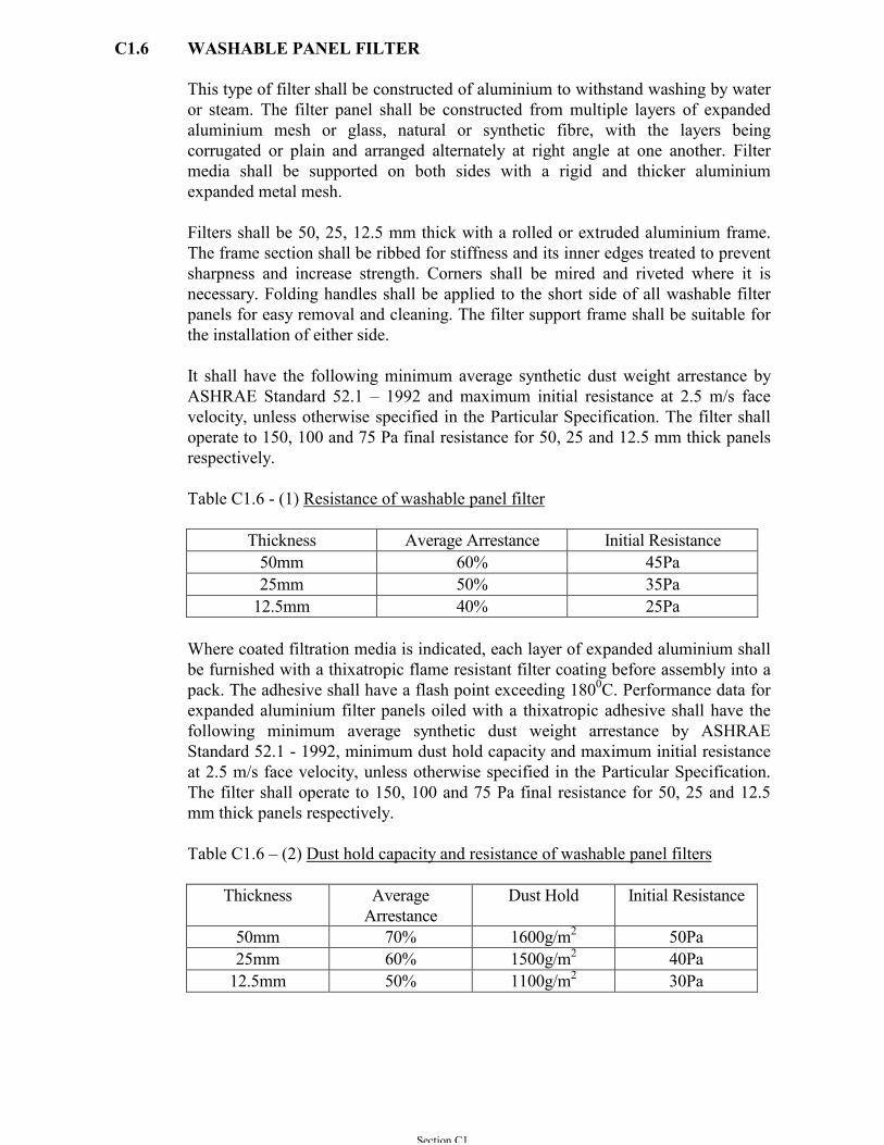
C1.6 WASHABLE PANEL FILTER
This type of filter shall be constructed of aluminium to withstand washing by wateror steam. The filter panel shall be constructed from multiple layers of expandedaluminium mesh or glass, natural or synthetic fibre, with the layers beingcorrugated or plain and arranged alternately at right angle at one another. Filtermedia shall be supported on both sides with a rigid and thicker aluminiumexpanded metal mesh.
Filters shall be 50, 25, 12.5 mm thick with a rolled or extruded aluminium frame.The frame section shall be ribbed for stiffness and its inner edges treated to preventsharpness and increase strength. Corners shall be mired and riveted where it isnecessary. Folding handles shall be applied to the short side of all washable filterpanels for easy removal and cleaning. The filter support frame shall be suitable forthe installation of either side.
It shall have the following minimum average synthetic dust weight arrestance byASHRAE Standard 52.1 – 1992 and maximum initial resistance at 2.5 m/s facevelocity, unless otherwise specified in the Particular Specification. The filter shalloperate to 150, 100 and 75 Pa final resistance for 50, 25 and 12.5 mm thick panelsrespectively.
Table C1.6 - (1) Resistance of washable panel filter
Thickness Average Arrestance Initial Resistance50mm 60% 45Pa25mm 50% 35Pa
12.5mm 40% 25Pa
Where coated filtration media is indicated, each layer of expanded aluminium shallbe furnished with a thixatropic flame resistant filter coating before assembly into apack. The adhesive shall have a flash point exceeding 1800C. Performance data forexpanded aluminium filter panels oiled with a thixatropic adhesive shall have thefollowing minimum average synthetic dust weight arrestance by ASHRAEStandard 52.1 - 1992, minimum dust hold capacity and maximum initial resistanceat 2.5 m/s face velocity, unless otherwise specified in the Particular Specification.The filter shall operate to 150, 100 and 75 Pa final resistance for 50, 25 and 12.5mm thick panels respectively.
Table C1.6 – (2) Dust hold capacity and resistance of washable panel filters
Thickness AverageArrestance
Dust Hold Initial Resistance
50mm 70% 1600g/m2 50Pa25mm 60% 1500g/m2 40Pa
12.5mm 50% 1100g/m2 30Pa
Section C1
C1.7 WASHING FACILITIES FOR WASHABLE FILTER
Where washable filters shall be provided, the Contractor shall provide one set ofduplicate cleaning tanks (one to wash, one to rinse). These tanks shall be such as toaccommodate all sizes of washable filters or if the Contractor wishes several sets oftanks may be provided to accommodate the various filter sizes provided.
The filter cleaning tanks shall be constructed of at least 1 mm thick stainless steelof grade 316 of American Iron Steel Institute minimum and suitably stiffenedaround the top edges by continuous external turned over inverted `u’ sections. Thetanks shall be 0.4 m deep. They shall be supplied with 18 mm drain down cock foremptying but shall also have external handles to facilitate turning over to clearsludge.
C1.8 AUTOMATIC VISCOUS FILTER
The filter shall comprise a frame or enclosure, filter plates, motor, drive and fluidtank. There shall be access to the tank containing the fluid to facilitate maintenanceand the tools and containers required for the removal of sludge shall be provided.Filter of this type shall have an average synthetic dust weight arrestance of not lessthan 85% by ASHRAE Standard 52.1 – 1992, unless otherwise specified in theParticular Specification. The design air velocity at the face of the filter shall notexceed 2.5 m/s and operating resistance shall not exceed 125 Pa at the design airvolume flow rate. To ensure that there is no carry-over of fluid from freshly wettedsurfaces the rate of drive shall be suitably adjusted and set or the filter shallincorporate shielding devices.
C1.9 AUTOMATIC RECLEANABLE HIGH VOLTAGE ELECTROSTATICFILTER
The automatic recleanable high voltage electrostatic filters shall be able to controlodours in the conditioned space and reduce the permanent deposition ofcontaminants in the space served. It shall have an average atmospheric dust-spotefficiency of not less than 95% by ASHRAE Standard 52.1 – 1992 and an initialresistance not exceeding 120 Pa at design air flow volume rate, unless otherwisespecified in the Particular Specification. For kitchen applications, it shall complywith the latest requirements of the Environmental Protection Department on thetreatment of gas fired kitchen exhaust air and the unit shall be leakage proof toavoid oil dripping.
The complete set shall consist of an ionizer-collector section power generator, a50mm aluminium washable panel filters section against over-spray and a motorizedwasher and adhesive applicator section. All parts shall be factory assembled into asectioned housing having an overall depth not greater than 1000 mm in direction ofairflow. Each section of the galvanized steel housing assembly shall incorporate apair of hinged, quick opening access doors permitting access for servicing of allinternal components; and a watertight, all welded, galvanized steel, drain panhaving drain connections. Access doors shall be sealed against leakage bycontinuous perimeter gaskets of closed cell neoprene.
Section C1
C1.9.1 Each ionizer-collector section shall be furnished with the requirednumber of one-piece cells of all aluminium construction. Each cell shallbe fitted with stainless steel slides for mounting on the tracks, whichform an integral component of the side access housing and to facilitateremoval of cells for servicing. Cell support framework shall becompletely open beneath the ionizer-collector cells to ensure completedrainage of wash water and excess adhesive, minimizing the possibilityof short circuits when high voltage power is restored followingcompletion of the wash cycle. Cells shall be designed so that highvoltage input terminals and their high volt rated insulators are locatedcompletely out of contact with the moving air-stream to avoid build upof dirt which could permit dissipation of high voltage charge and reduceair cleaning efficiency. The high voltage bus bars and contactors shall beinherent to the design of each cell and shall permit cell removal withoutdisconnecting any high voltage wiring. Insulators shall be fully exposed,for ease of cleaning, when cells are removed for service. Cells shall bedesigned for full-face ionization and shall have completely flat collectorplates to prevent buildup of residual, inaccessible dirt accumulations.
C1.9.2 Dual voltage power packs which are designed to provide high voltage tothe ionizer circuit and to the plate circuit respectively shall be connectedto each ionizer-collector section. The power packs shall be of solid statedesign, having multiple steps of output voltage adjustment, to includerelays of remote indication of primary input and secondary output, shallhave “fail-safe” low voltage relays to interrupt power to the ionizercircuit in the event of a malfunction in the plate circuit. High voltageconnections between the high voltage output terminals and the bus barterminals mounted on the ionizer-collector section access door shall beadequately installed. Power pack covers shall each to include primaryand secondary neon glow lamps, a circuit breaker, and a manual resetbutton. Two time delay safety type door interlock switches, with suitablelength of safety chain and wiring in series circuit for the power pack,shall be furnished to cut-off the power supply whenever the door isopened.
C1.9.3 Each washer and adhesive applicator section shall incorporate slide-intype, perforated, galvanized steel air distribution baffles and a motor-driven mobile header assembly. The mobile header assembly shall beconnected to the inlet water solenoid valve and to the adhesive pump bymeans of non-snag, expanded PVC hose with a braided polyesterexterior protective cover. Rotating washer arms, each equipped withadjustable, multi-directional, 360o washer spray nozzles, shall be drivenby reactive force to the high inlet water pressure. The removable brassadhesive nozzles shall be mounted on a separate, fixed, vertical headerforming an integral component of the mobile assembly. The filteradhesive shall be cold water soluble and non-flammable. A rotary gearadhesive pump with bronze impeller and sufficient adhesive for at leastfour reconditioning cycles shall be furnished.
C1.9.4 The washer supply water solenoid valve, the manifold drive motor, andthe manifold limit switch shall be pre-wired to an accessible, internallymounted terminal box. The washer control enclosure access door shallincorporate a status light to indicate when the reconditioning cycle is
Section C1
energized. An internal panel shall be equipped with a combination ofLED status lights and a digital readout to indicate which part of thereconditioning cycle is in operation. The digital readout shall be visiblethrough a window in the control cover. The complete automatic cleaningby reversing the polarity of the filter element, wet washing by waterspray and adhesive application shall be initiated manually orautomatically through a push button actuated, internally fused, all solidstate, program timer control, with adjustable timer to control drip andfan dry cycles.
C1.10 HIGH EFFICIENCY PARTICULATE AIR (HEPA) FILTER
The HEPA filter shall have minimum efficiency of 99.97% in removing smallparticles of sizes larger than 0.3 micrometer from air by Underwriters LaboratoriesUL 586 - method of Dioctylphthlate (DOP) Penetration Test. This makes use of ahigh efficiency glass paper medium and great surface area of medium per cross-sectional area of the filter. It shall reach this rated efficiency when the velocity ofthe gas passing through the media is 1.5 to 2.5 m/s. Unless otherwise specified inthe Particular Specification, a normal HEPA filter of a size 600 mm square with300 mm thickness, shall have a rated flow of 0.47 m3/s, at a maximum pressuredrop of 250 Pa, and about 23 m2 of filtering media. The filter shall operate to 600Pa final resistance.
For clean rooms and clean zones, the HEPA filter shall be selected to meet class100 of air cleanliness by Federal Standard 209E – Airborne Particulate CleanlinessClasses in Clean Rooms and Clean Zones, unless otherwise specified in theParticular Specification.
Filter shall be constructed from a continuous sheet of the filter medium folded overa separator of aluminium of other approved material to form closely spaced pleats,the whole being sealed into a casing with hard setting synthetic resin cement. Thisshall enable slower medium velocity and increased efficiency. The media of spacefilter paper produced wholly from glass microfibres, shall be inert, non-hygroscopic, vermin proof and shall not support bacteria growth. The filter mediashall be treated with organic binder materials to provide binder, fungicidal andwaterproofing properties.
C1.11 GAS FILTER
The gas filters shall remove contaminating gases from the air by absorption oradsorption. It shall comprise a robust enclosure inserted with module banks whichcontain evenly disposed chemical media. The complete unit is to be factoryassembled and manufactured by the same manufacturer. All joints between therobust enclosure and the module banks shall be effectively sealed to eliminate airbypass and to ensure the optimum removal efficiency. Their supports shall beconstructed from steel protected against corrosion and designed to providemechanical protection to the module banks. The chemical media shall be ofuniform thickness packed to ensure that compacting does not occur in use.
The chemical media shall consist of solid sorbents including activated carbons forcommon volatile organic compounds in indoor air and activated alumina suitably
Section C1
impregnated with potassium permanganate for formaldehyde and other gaseouscontaminants. The combined media shall be able to operate normally at temperature0 oC to 45 oC and relative humidity 10 to 95 %. It shall be inorganic, non-toxic,non-flammable and shall not support bacterial or fungal growth.
The gas filters shall be selected to give a removal efficiency of not less than 80%,residence time of minimum 0.2 seconds and an initial resistance not exceeding 125Pa at 1.5m/s face velocity, unless otherwise specified in the ParticularSpecification. Laboratory analysis of media samples to establish life cycles andremaining life shall be submitted to the Architect for approval.
C1.12 AUTOMATIC RECLEANABLE FILTER
Filter media shall be made of reinforced fibre-glass or other suitable syntheticmedium mounted on a rotatory tube or a fixed drum. When a preset differentialpressure between dirty and clean airsides of the filter is exceeded, the cleaningoperation shall be initiated. For the rotatory tube design, the carrier tube shall rotateand suction nozzle with vibrator motor shall move along the filtering surfaces. Forthe fixed drum design, an air valve installed at the downstream of the filter shallinject compressed air pulse-jet opposite to normal air flow direction. As a result,dirt particles will be pulsed away from the filter and collected in concentrated forminside a collection chamber or an external vacuum cleaner/central vacuum cleaningsystem connected outside the filter chamber.
Cleaning shall be carried out both during downtimes of the air-conditioning/ventilation system and during plant operation. The medium shall havea filtering efficiency of EU class 9 by Eurovent 4/4 and 4/5. The initial resistanceacross the whole unit shall not exceed 250 Pa at design air flow volume rate and thefinal resistance shall not be more than 500 Pa, unless otherwise specified in theParticular Specification.
The internal surface of the filter set shall be absolutely smooth and that of the bottomshall be in trough form with drain so that water can be drained off in case of wetcleaning.
The construction of the service door shall be identical to the casing panel. Non-agingsteel-inlaid labyrinth seal shall be integrated into the door leaf. Each door shall befitted with at least two double lever locks with bolts. Safety cams or chains shall beprovided for pressure side doors. All the surfaces of the casing shall be protectedagainst atmospheric corrosion by plastic powder coating.
The whole cleaning cycle shall be actuated and controlled by a sequence controllerwith basic operation of :-
(a) Reverse blowing by air pulse
(b) Allow few minutes time interval for the dust and other contaminantparticles to settle at the collector trap
(c) Operate of the vacuum cleaner/central vacuum cleaning system for a fewminutes
Section C1
(d) Actuate alarm for disposing the contaminant particles when thecollecting bag is 80 % full
C1.13 FILTER PRESSURE DIFFERENTIAL MEASUREMENT ANDINDICATION
A differential pressure gauge of the inclined manometer type shall be provided foreach filter bank.
The gauge shall incorporate a graduated scale on which the reading of maximumpressure drop shall occur in not less than 75% of the total scale length.
C1.14 ADDITIONAL REQUIREMENTS (SPARE FILTER MEDIA)
The Contractor shall replace all filters used during testing and commissioning stageand in addition provide the following to the Architect for use by Client’s operationstaff during Maintenance Period :-
(a) For disposable type filters, one complete set of unused filter cells.
(b) For washable type filters, 20 % in number of the filter cells. These shallbe new and in good condition. Besides, 10 litre of the approved cleaningdetergent per filter installation shall be provided. Regarding filters ofviscous type, a drum or drums of fluid amounting to one completechange or 10 litres per filter installation where thixatropic coatings areused shall be provided.
(c) For renewable type filters, one complete set of unused filter media.
(d) For gas filters, one complete set of unused filter cells.
Within one month before Maintenance Period is certified to be complete, all abovefilter cells/media shall be replaced with new one. In addition, 10 litre of theapproved cleaning detergent per washable filter installation shall be provided.Regarding filters of viscous type, a drum or drums of fluid amounting to onecomplete change or l0 litres per filter installation where thixatropic coatings areused shall be provided.
C1.15 AUTOMATIC RECLEANABLE HEPA FILTER
The whole unit shall be of heavy duty proprietary made air-tight construction. Itshall be coated with polyester powder to protect from atmospheric corrosion and tominimize internal friction. By the modular construction, each filter chamber of theunit shall be isolated from the air stream without affecting the operation of the unitwhile cleaning or replacing the filter cartridges within a particular filter chamber.The filter cartridge shall be designed as drawers by sliding in or pulling out forreplacement and repairing services from the front panel and entirely from the cleanairside. There shall be no contamination on the filter unit and the environmentduring the replacement. At the bottom, dust collection containers shall be mountedto each filter chamber by clamps via inter-connecting funnel sections.
Section C1
Automatic cleaning is conducted by using a counter-current compressed air purgesequence. Filter shall be cleaned periodically by compressed air, which is blown incounter-flow direction to the filter cells from nozzles actuated by pneumatic systemfrom the clean airside. A digital measuring and indication device shall be providedto show the differential pressure of all filter cells in one filter chamber. Cleaningsystem shall be complete with an electronic self-diagnostic system keeping checkwith the differential pressure, filter cleaning cycle, replacement period and suddenpiercing of the filter medium.
Filter media shall be made of reinforced fibre-glass or other suitable syntheticmedium with filtering efficiency of not less than EU class 13 by Eurovent 4/4. Theinitial resistance across the whole unit shall not exceed 1500 Pa at design air flowvolume rate and the final resistance shall not be more than 2400 Pa, unlessotherwise specified in the Particular Specification.
C1.16 BIO-OXYGEN GENERATOR (AIR PURIFIER)
The bio-oxygen generator shall be capable of reducing bacteria and airbornecontaminants within the area concerned.
All components of the bio-oxygen generator, which are within the air stream, shallcomply with the latest requirement of Fire Services Department.
The bio-generator shall have removal efficiency of not less than 95% of TotalBacteria Count (TBC) Test, 95% of cigarette smoke particles and 80% of odours,unless otherwise specified in the Particular Specification. The ozone levelgenerated in the indoor environment shall be less than 0.05 ppm and thebackground ozone level shall not in excess of the safety standards specified byOccupational Safety and Hygienic Association (OSHA), USA.
Each unit shall be suitable for ductwork mounting and shall consist of electrodetubes and power generator with built in output regulator as described below :
(a) The electrode tube shall consist of electrodes, glass tube and a threadconnector at the base of the tube for connection with the tube socketprovided at the power generator. Each tube shall be covered by stainlesssteel mesh and earthed by the grounding leaf spring connected to thepower generator. No high voltage part shall be exposed and accessible.All part in contact with air shall be corrosive resistant. The requiredquantity and output of the electrode tubes for each air handling plantshall follow manufacturer’s recommendation, which shall be sufficient tohandle the design air flow rate and the volume of the room being served.
(b) The power generator shall be able to operate on 220V/50 Hz single phasesupply. It shall generate appropriate supply to match with the operationrequirements of the electrode tubes. It shall be equipped with built-inregulator for output adjustment and shall consist of on/off indicator lamp,overload protection device, tube sockets, control knob for regulatorsetting and on/off switch.
Section C1
C1.17 ULTRA-VIOLET STERILIZING LIGHT (UV)
The ultra-violet sterilizing light shall be UL listed and all components within the airstream shall comply with latest requirement of Fire Services Department. It shall becapable of killing mould and other airborne microbial contaminants within the areaconcerned such as cold, flu and measles viruses, Legionella, tuberculosis and otherbacteria, viruses and mould spores.
The sterilizing light shall have one pass bacteria removal efficiency not less than95% of Total Bacteria Count (TBC) Test, unless otherwise specified in theParticular Specification. The ozone level generated in the indoor environment shallbe less than 0.05 ppm and the background ozone level shall not in excess of thesafety standards specified by Occupational Safety and Hygienic Association(OSHA), USA.
Each unit shall be suitable for ductwork mounting and shall consist of emitter tubeand power generator with built-in output regulator as described below :
(a) The emitter tube shall consist of electrodes, glass tube and a threadconnector at the base of the tube for connection with the tube socketprovided at the power generator. Each tube is capable of producingbroadband UVC waveform in the range around 250-nm mercury spectralline. The required quantity and output of the emitter tubes for each airhandling plant shall follow the manufacturer’s recommendation, whichshall be sufficient to handle the design air flow rate and the volume ofthe room being served.
(b) The power generator shall be able to operate on 220V/50 Hz single phasesupply. It shall generate appropriate supply to match with the operationrequirements of the emitter tubes. It shall be equipped with built-inregulator for output adjustment and shall consist of on/off indicator lamp,overload protection device, tube sockets, control knob for regulatorsetting and on/off switch.
C1.18 WATER SCRUBBER
Refer to Sub-section A5.5.6.
Section C2
SECTION C2
DUCTWORK AND ACCESSORIES
C2.1 GENERAL
Ductwork shall be off site pre-fabricated according to the requirement as specifiedin the Particular Specification. The ductwork shall be fabricated from good qualityfull sized zinc coated hot dipped galvanised flat steel sheet to BS EN 10142, GradeDX51D+Z, coating type Z275 unless otherwise specified in the ParticularSpecification or the Drawings.
C2.2 OFF SITE PRE-FABRICATION
The development of components for round, oval and rectangular ductwork shall becarried out by a computer software which can produce all development plans fromthe proposed ductwork layouts including all type of ductwork fittings andaccessories. The software shall be able to work out the development plans withutilization factor not less than 94%. Copy of the proposed software details shall besubmitted for approval prior to production.
The above utilization factor is based on a ratio of the Standard Size StraightDuctwork: Ductwork Fittings, which is 7 : 3. For standard straight ductwork, theutilization factor is about 100% and that for fittings is about 80%. If the ratio ofDuctwork to Fittings is not 7 : 3, the overall utilization factor shall be submitted tothe approval of the Architect.
The remaining materials that cannot be used for fabrication of ductwork shall beused for other purpose or as least to be recycled instead of being disposed of asscraps. The software used shall also be linked to the Numerical Control CuttingMachines, such as the Plasma Cutting System for the cutting, development andforming of the required ductwork components and accessories. Copy of theproposed Numerical Control Cutting Machines details shall be submitted forapproval prior to production.
Automatic or semi-automatic machines shall be employed for the bending, foldingand assembly of ductwork from sheet metal components developed. Proper machinesare required for the manufacturing of all ductwork accessories including flanges,stiffeners, splitter dampers, etc in order to enhance quality.
Construction and materials used for ductwork, fittings and accessories shall be inert,non-hygroscopic, vermin and moisture proof, asbestos and CFC free, and shall notsupport growth of bacteria.
Bends and branch vanes, dampers etc. shall be of the same material as used for theductwork and/or of heavier gauge, securely mounted.
Section C2
C2.3 SPECIFICATION AND STANDARDS
Ductwork shall comply with the latest edition of the following HVCA publicationswith additions or amendments as required by this General Specification and/orelsewhere in the Contract Documents.
(a) DW/144 Specification for sheet metal ductwork (low-medium- and highpressure)
(b) DW/151 Specification for plastics ductwork
(c) DW/191 Guide to good Practice glass fibre ductwork.
Where any part of the installation is not covered by the above, therecommendations of the latest edition of "Low Pressure Ductwork ConstructionStandards" and "High Pressure Ductwork Construction Standards" issued by theSheet Metal and Air Conditioning Contractors' National Association (SMACNA)Inc. USA shall be applied.
C2.4 FLEXIBLE DUCTWORK
The flexible ductwork shall have a liner and a cover of tough tear-resistant fabricequal in durability and flexibility to glass fibre fabric. The fabric shall beimpregnated and coated with plastics. It shall be reinforced with a bondedgalvanised spring of stainless steel or other approved wire helix between the linerand the cover. An outer helix of glass fibre cord or equal shall be bonded to thecover to ensure regular convolutions. Flexible ductwork without a liner may not beused.
In no cases shall material containing asbestos fabric be used.
Alternatively, flexible ductwork shall consist of flexible corrugated metal tubing ofstainless steel, aluminium, tin plated steel or aluminium coated steel. The metalsurface(s) may be coated with a plastics material.
The leakage from any section of flexible ductwork shall not exceed 1% of the localdesign air flow rate at the local maximum static pressure.
Flexible ductwork shall be suitable for an operating temperature range of -5° C to 90°C and shall comply with BS 476 Part 5, Rating Class P; Part 6 having an index ofperformance not exceeding 12 of which not more than 6 should derive from the initialperiod of test; Part 7 Class 1 (surface of very low flame spread) unless otherwiseindicated.
C2.5 DUCTWORK FOR CORROSIVE FUMES
Ductwork used to carry corrosive fumes shall be of non-corrosive material. WherePVC material is used, the minimum thickness shall be 2.4 mm.
Plastic ductwork and all associated moulded or extruded sections, angles andfittings shall be unaffected by the range of substances conveyed and under the
Section C2
conditions indicated. Unless otherwise indicated, and providing the requirementsabove can be met, sheet material shall be pressed unplasticised PVC sheetcomplying with ISO 6453. Where PVC ductwork is thermally insulated or is notreadily visible, Type A3 sheet shall be used; elsewhere Type Al shall be used.
Any plastic ductwork system incorporating a heater battery shall be installed suchthat no part of the system is impaired by the heating effects of the battery or itscasing.
Circular ductwork up to 300 mm shall preferably be fabricated from unplasticisedPVC pipe complying with ISO 3472 and ISO 3473. Unless otherwise indicated, thecolour of sheet and pipe shall be industrial grey. Ductwork shall be constructed(thickness, angles, stiffness etc.) in accordance with Specification DW/151 part 1uPVC.
Where any part of the installation is not covered by "DW/151", then therecommendations of the latest edition of "Thermoplastic Ductwork (PVC)Construction Manual" issued by the Sheet Metal and Air Conditioning Contractors'National Association (SMACNA), Inc. USA shall apply.
The methods of construction recommended in HVCA Specification DW/151 shallbe used, i.e. cemented joints shall be used for circular (pipe) jointing and hotgas/filler rod, welding shall be used for all other fabrication. For circular ductworkconstructed from pipe, sufficient angle joints shall be provided to enable theductwork to be dismantled in the space available. Where so directed by theArchitect, all welders shall carry out the test detailed in HVCA SpecificationDW/151.
The requirements of HVCA Specification DW/151 with regard to expansion joints,ductwork supports, access doors and gaskets shall be met.
Extruded or moulded sections, angles and fittings shall be of the same plasticmaterials and colour as the sheet or tube.
PVC ductwork shall not be used in situations where it will be subjected totemperatures of 50o C and above. Where heater batteries are required in the system,the PVC ductwork shall be isolated from these by a suitable length of stainless steelductwork, generally as described for glass fibre ductwork in Sub-section C2.6.
C2.6 GLASS FIBRE DUCTWORK
C2.6.1 General
Where specified in the Particular Specification or the Drawings, glassfibre ductwork made from 25 mm/38 mm thick resin bonded glass fibrein rigid board form may be used. The board shall have an integralexternal vapour barrier of hard grade, flame retardant, damage-resistantreinforced aluminium foil and an internal smooth, durable acrylic coatingthat isolates the glass fibre substrate from the air stream and inhibitspenetration of the insulation by dirt, dust, micro organisms and otherpollutants.
Section C2
Special attention shall be paid to ensure that the materialitself/fabrication/erection of the ductwork does not contribute towardssuspected health hazard.
Thickness of the ductwork board to be used shall be selected inaccordance with manufacturer’s ductwork sizes, static pressure andreinforcement schedule and recommendation.
C2.6.2 Specification and Standards
Specification and Standards for glass fibre ductwork shall comply withthe recommendations of the latest edition of HVCA Publication DW/191Code of Practice for resin bonded glass fibre ductwork, or the "Fibrousglass Ductwork Construction Standards" issued by the Sheet Metal andAir Conditioning Contractors' National Association, Inc. USA. Theflexural rigidity rating of the rigid glass fibre board shall be 8OOE1 (33.7kg/m2) as defined in the above Standards. Glass fibre ductwork shallmeet with the requirements of NFPA 90A and 90B by complying withthe requirements of Under-writer’s Laboratories Standard for safety UL181 for Class 0 ductwork.
Glass fibre ductwork to be used shall resist fungal or bacterial growthwhen subjected to microbial attack as described in ASTM C665 andStandard Practices ASTM G21 (fungus test) and G22 (bacteria test).
Glass fibre ductwork shall be easily cleanable using methods andequipment described in North American Insulation ManufacturersAssociation (NAIMA) Publication AH-122, Cleaning Fibrous GlassInsulated Ductwork Systems.
C2.6.3 Mounting if Fittings
Where the following items are installed in a ductwork, a suitably sizedsection of galvanised sheet ductwork shall be installed complete withindependent supports and insulation :
(a) Electric or hot water etc. ductwork heaters and access panels(b) Volume control dampers(c) Fire dampers and access panel(d) Fan and access panel
C2.6.5 Mountings of Instruments
All control/metering probes, etc. which require mounting in fibre glassductwork shall be adequately supported by a sheet metal panel securelyfixed to the internal face of the ductwork. The Contractor shall fix aremovable insulated cover over the complete probe to ensurecondensation will not occur on any exposed metal surfaces.
C2.6.5 Special Tools and Manufacturers Fabrication Instructions
The construction and installation including all cutting tools employed tofabricate the ductwork shall be strictly in accordance with the
Section C2
recommendations of the fibre glass ductwork manufacturers instructionsissued for the correct installation of their product. Fabrication andinstallation by any method other than that endorsed by the fibre glassductwork manufacturer may be rejected by the Architect.
C2.7 PHENOLIC FOAM DUCTBOARD DUCTWORK
C2.7.1 General - Where specified in the Particular Specification or theDrawings, pre-insulated ductwork made from 20 mm thick rigid closedcell phenolic foam in rigid board form may be used.
C2.7.2 The ductwork material shall be covered with a layer of vapour barrier onboth board facing. The vapour barrier shall be of minimum 20 micronthick aluminium foil. The circumferential and longitudinal seams of thevapour barrier foils shall be sealed with self-adhesive foil tape asspecified in Sub-section C11.4.3.
C2.7.3 All material shall have a class 'O' fire rating and certificate from FireServices Department. Details refer to Sub-section C11.2.1. Low smokeemission shall comply with BS 5111 Part 1 and shall be CFC free.
C2.7.4 The flange system for the phenolic foam ductwork shall be designed toeliminate the effect of "Cold Bridge" and for the purpose of sealing, theflanges shall be coated with fire resistant gaskets and securely mountedwith sufficient bolts, nuts and clips. An established joining system shallbe employed in connecting the ductwork and accessories such as airoutlets and dampers. The joining system shall be approved by theArchitect.
C2.7.5 Where the following items are installed in the ductwork, they shall beadequately supported by a sheet metal panel securely fixed to the internalface of the ductwork with due consideration to ensure that condensationwill not occur on any exposed metal surface :-
- Ductwork heaters- Volume control dampers- Fire dampers- Fans & access panels
C2.7.6 The construction and installation including all cutting tools, adhesives,flange system shall be strictly in accordance with the recommendationsof the phenolic foam ductboard manufacturer's instruction.
C2.8 DAMPERS - GENERAL
The respective functions, types and general constructional requirements of dampersshall be in accordance with the HVCA ductwork specification DW/144 unlessotherwise indicated, sufficient dampers shall be provided to regulate and balancethe system. Dampers on grilles or diffusers shall be used for fine control only.
Section C2
All dampers shall be of flanged type for connection to ductwork and shall besufficiently rigid to prevent fluttering. Air leakage rate for dampers shall be testedaccording to EN 1751 Section 3 when the damper is in the closed position. Fordampers installed for shut- off purpose, the maximum air leakage rate shall betested according to EN 1751 Section 4.
Air volume control dampers shall be of the aerofoil, double skin, opposed bladetype with low pressure drop and noise regeneration characteristics. Damper bladesin rectangular ductwork shall not exceed 225 mm in width and 1500 mm in length.Blades shall be of hollow section constructed from the same material of theductwork or of stainless steel encapsulating an internal double contoured steellongitudinal reinforcing bar, mounted on square section steel spindles. Bearingsshall be of nylon material and the units shall be of low-leakage design byincorporation of synthetic trailing edge seals and a peripheral gasket which shall betested according to BS 476 Part 6 and 7 and shall be approved by the Fire ServicesDepartment. All manually and automatically operated dampers shall include ameans for indicating externally the position of the blades. Manual dampers shallinclude a device for positioning and locking the damper blades. The positions of alldampers 'as-set' after final regulation shall be indelibly marked at the adjustingdevice.
Each air volume control damper in the ductwork shall be fitted with a non-corrodiblelabel stating the actual air flow in m3/s when in the fully open position, its overallcross sectional area, and the degree to which the damper has been closed in order toachieve the design or actual air flow.
Unless otherwise indicated, quadrants and operating handles shall be of die-castaluminium or other material approved by the Architect with the words 'OPEN' and'SHUT' cast on the quadrant.
Quadrants shall be securely fixed and the damper spindles shall be closely fitted in thequadrant hubs to prevent any damper movement when the damper levers are locked.
Access openings with readily removable air sealed covers shall be provided adjacentto all dampers. Subject to limitations of ductwork size the dimensions of accessopenings shall not be less than 300 mm x 300 mm and they shall be located so as toafford easy access for inspection and maintenance.
C2.9 BUTTERFLY, BIFURCATING AND MULTILEAF DAMPERS
Butterfly dampers shall each consist of two plates, edge seamed, of at least thesame thickness as the material from which the associated ductwork is made, andrigidly fixed to each side of a mild steel operating spindle, the ends of which shallbe turned and housed in non-ferrous bearings.
Bifurcating dampers shall be of 2 mm thick sheet for sizes up to 450 mm square,for larger sizes the thickness shall be as specified. The damper blades shall berigidly fixed to square section mild steel spindles, the ends of which shall be turnedand housed in non-ferrous bearings.
Each leaf of a multileaf damper shall consist of two plates of material of the samethickness as the associated ductwork and rigidly fixed to each side of an operation
Section C2
spindle, the ends of which shall be housed in brass, nylon, oil impregnated sinteredmetal, PTEE impregnated or ball bearings. The ends of the spindles shall be linkedso that one movement of the operating handle shall move each leaf for an equalamount. The mechanism shall be located outside the air stream.
For system static pressure below 1000 Pa or ductwork velocity below 12 m/s, bladeof at least 50 mm wide shall be used. For static pressure at or above 1000 Pa, atleast 100 mm wide blade shall be used. Central blade reinforcement bar shall beprovided for damper span longer than 1500 mm. Single module of a damper shallnot exceed 2000 mm width and 1000 mm height.
Alternatively, multileaf damper blades may be of a single plate, at least 1.6 mm thickand suitably stiffened, and the blade linkages may be within the ductwork. Thesedampers shall have bearings and inspection doors as specified in Sub-section C2.8.
C2.10 SELF-CLOSING (NON-RETURN) DAMPERS
Self-closing dampers shall present a minimum resistance to air flow under runningconditions and take up a stable position in operation. Maximum resistance shall bepresented under reverse air flow conditions such that they will be forced to closeand remain so. Resilient strips or other purpose made devices shall be provided toprevent the damper from rattling and as an aid to air sealing under reverse flowconditions.
Blades shall be rigidly constructed of steel or aluminium sheet of not less than 0.8mm (22 gauge) and shall be free of all buckles. Blades of less than 300 mm inheight shall be fitted with a 3 mm (10 gauge) bright steel spindle at each end.Blades of 300 mm and over in height shall be fitted with a 8 mm bright steelspindle at each end. Spindles shall be carried by sealed ball bearings. Bearing shallbe accessible for cleaning and lubrication and shall be mounted in a rigidgalvanised steel frame. The maximum length of each blade without a centralbearing shall be 1000 mm.
C2.11 FIRE, SMOKE AND COMBINED FIRE SMOKE STOP DAMPERS
C2.11.1 Fire and Smoke Stop Dampers
Fire or Smoke dampers shall be provided in ductwork in the followinglocations:-
(a) Wherever a ductwork passes through a floor slab or a fireresisting wall which is expressly built for the purpose ofpreventing the spread of fire.
(b) Other locations where requirements of compartmentalisationare stipulated in the Code of Practice for FRC under thelatest edition of the Building Ordinance of Hong Kong.
(c) Other locations as required by the Particular Specificationand the Drawings.

Section C2
Fire or Smoke dampers used singly or in combination shall have anoverall fire rating not less than that indicated and certainly not less thanthat for the wall or floor slab in which they are situated.
In all cases, evidence of fire rating in accordance with ISO 10294Classification E (BS 476 part 8) or NFPA 90 A with 2-hour UL firedamper label shall be provided by an independent testing organisationapproved by the Architect. All Fire or Smoke dampers shall also beapproved by the Fire Services Department.
Fire or Smoke damper blades of proprietary made shall be constructed tothe approved and recognised testing authority and posses a ratingequivalent to the fire resistance of the structure it protects.
Local made fire or smoke damper blades shall comply with therequirements of the Circular Letters issued by Fire Services Departmentand the Building Ordinance of HKSAR. These blades shall be housed ina corrosion resistant casing constructed to avoid distortion due to stressin fire conditions. Stainless steel spring tempered flexible gasket shall beinserted between the blade and the casing for elimination of closingfriction and retardation of smoke. Provision shall be made toaccommodate expansion of the damper blades within the casing in fireconditions to prevent jamming and to retard the spread of smoke. A Fireor Smoke damper installation frame supplied by the same manufacturershall also incorporate provision for expansion within the surroundingstructure together with masking flange for building into the structure.
Fire or Smoke damper assemblies for installations in corrosiveenvironments shall be fabricated from suitable materials resistant to thecorrosive substances and environments indicated. Alternatively, thematerial may be coated with a protective finish to produce the sameeffect.
Power fail-safe remote electromagnet release shall be provided toexplosion hazardous areas. The electromagnet shall normally notconsume more than 10mA by 220V AC supply or 120mA by 24VAC/DC supply. The Contractor shall be responsible for the power fail-safe fire dampers to the fire control relay at the fire service control panel.
Each Fire or Smoke damper casing shall be air tight, continuouslywelded and clearly marked with a permanent indication of the directionof air flow and the side at which the access/maintenance opening islocated.
The folded continuous interlocked blade type of damper may be used forvertical or horizontal ductwork applications. The closing force for thesetype of dampers shall be provided by stainless steel spring or springs. Anautomatic locking device shall be provided to ensure that the blades areheld in the closed position after release.
Spring actuated pivoted single-bladed or multi-bladed dampers may beused for vertical or horizontal ductwork applications.

Section C2
Multi-bladed dampers shall be provided with a means to ensure that allthe blades close simultaneously.
Gravity operated multi-bladed fire dampers shall not be used in verticalductwork.
Gravity operated single bladed dampers may be used for horizontalductwork provided means are incorporated which ensure reliable andpositive closure when operating in maximum air flow rate conditions.
Locally fabricated gravity fire dampers shall be provided with a coaming orcasing of the same material and shall be physically bolted to the structurethrough which the ductwork penetrates.
Fire or Smoke dampers shall be rated in accordance with the fire rating ofthe wall, ceiling or floor etc. as shown in the drawings and the ParticularSpecification, to the requirements of the Fire Services Department andacceptable by the Architect.
For locally fabricated fire dampers, the thickness of metal for the dampersshall comply with the Circular Letters issued by Fire Services Departmentand the Building Ordinance of HKSAR.
Where gravity acting off-centre pivoted dampers incorporate spindlebearings long term corrosion effects shall be minimised by the choice ofsuitable materials. Bearings shall be sealed or capped to exclude dirt anddust. Damper blades shall close to comply with the stability and integrityrequirements of ISO 10294 Classification E (BS 476 Part 8).
For high velocity air systems, fire/smoke dampers shall provide 100%free area when damper blades are in the open position to give minimuminterference to the air flow.
Unless otherwise indicated, each Fire or Smoke damper shall be held inthe open position by a corrosion resistant retaining device incorporating afusible element which shall operate at a temperature of 69 oC, unlessotherwise indicated.
Fire or Smoke dampers shall be located in a position and be of a typewhich could facilitate periodic one handed manual release and re-settingfor test purpose.
Proprietary access doors shall be installed adjacent to each Fire or Smokedamper and, in the case of conditioned air or kitchen exhaust ductwork,the access doors shall be encapsulated and pre-insulated.
C2.11.2 Combined Fire and Smoke Stop Dampers
Combined fire and smoke stop dampers shall be tested to ISO 10294classification ES and approved by the Fire Services Department.
The dampers shall be of stainless steel, aerofoil bladed construction withthe blades held in stainless steel bearings and framed in stainless steel
Section C2
spring tempered flexible gasket. The blades shall have trailing edgesforming an interlocking metal to metal seal when the blades are closed,providing tight, low leakage closure of the air path and maximumimpedance to the passage of smoke and products of combustion fromeither flow direction.
The blades shall be driven by externally mounted and totally enclosedstainless steel gearbox and drive mechanism providing accurate bladecontrol with minimum torque and without accumulative backlash.
The damper casing shall be of double-skin galvanized steel constructionwith continuously welded corners and integral spigot connections. Thedampers shall be supplied complete with the manufacturer-installedframes.
Each damper shall have an externally replaceable combination thermalactuator and fusible link completely exposed to the air stream.
In addition to the thermal actuation/fusible link, the damper shall benormally held by electromagnetic device with power rating of not morethan 3.5W. The damper shall be released to the closed, or fail-safeposition within 1 second by an independent closure spring on loss ofpower supply, either by genuine power failure or by the zone fire signalactuated by the smoke detection system.
The damper shall be automatically reset on resumption of power supplyby built-in motor of 220V AC or 24V AC/DC.
The whole control mechanism and actuation shall be of the samemanufacturer and mounted inside a totally enclosed casing for protectionagainst airborne contamination and to ensure unique reliability.
For smoke extraction at 250oC for 1 hour application, damper controlactuator shall be totally shielded by a proprietory thermal insulationjacket. The whole damper assembly shall have undergone a hightemperature operation test followed by a leakage test at 1500Padifferential pressure and ultimately approved by the Fire ServicesDepartment.
Leakage rate shall be tested in accordance with UL555S.
Fire rating shall be to BS 476 and the whole damper assembly shall haveundergone a temperature exposure test by an independent laboratory inaccordance with the temperature and duration as indicated in BS 476.Test report shall be submitted to the Architect for reference.
C2.12 MOTORIZED SHUT-OFF DAMPERS
Motorized shut-off dampers shall be similar to fire/smoke dampers and shall beopen or close by motorized mechanism. Each of the damper shall be in “Open”position normally, but shall be closed in case of fire. The motorized mechanism
Section C2
shall be actuated by associated automatic fire detectors. Air leakage rate formotorized shut-off dampers shall be tested according to EN 1751 Section 4.
C2.13 TERMINAL DAMPERS
Grilles and air diffusers with rectangular neck connections shall be provided withan opposed blade damper, screwed or riveted to the neck connection and designedspecially to facilitate final balancing of the system.
Damper frames, blades and operating mechanism shall be constructed from analuminium alloy or, alternatively, formed mild steel suitably finished to giveprotection to the material during the design working life.
Blades shall be made of solid section material and shall be firmly held in positionby a spring steel retaining mechanism. The blade setting mechanism shall beaccessible through the grille or diffuser blades and shall be suitable for operationwith an “Allen” key. Where dampers are visible through the grille or diffuser theyshall be finished with a matt black paint.
C2.14 ACCESS DOORS AND PANELS TO DUCTWORK, CABINETS, COLDSTORES
Unless otherwise indicated, locally fabricated Access Doors or Panels shall beconstructed of marine plywood on seasoned teakwood frames in accordance withthe Architect's issued Standard Details, suitably insulated where necessary andfinished with at least three coats of shellac, lacquered and polished.
The insulation in the door shall be equal to that of the ductwork or cabinet intowhich it is installed. When closed, the door shall be effectively vapour sealed.
On doors through which a man can pass, the opening handle must also be operablefrom the inside of the door.
Access doors and panels on factory made equipment shall be approved by theArchitect.
All fittings and screws shall be made of brass.
Access doors or panels to ductwork heaters shall be constructed in accordance withthe Architect's issued Standard Details for ductwork heaters.
Access doors shall be of proprietary manufacture, double-skin, 25 mm sandwich G.I.construction with fibreglass or CFC-free foam insulation infill. Access doors shall beof lift off type having a minimum of 4 cam-lock action retaining locks for fixing toductwork frame. Gaskets shall conform to DW/144 & 143. Access doors shall besupplied and fitted with retaining chain tied back to the frame. Multiple screw fixingsshall not be allowed.
Section C2
C2.15 DUCTWORK FLANGES
All rectangular ductwork shall be flange joints. Flanges shall be of a proprietarytype, tested and certified for air leakage and deflection to DW/144. Certificatesmust be submitted during the equipment submission period.
The proprietary ductwork flanges shall be roll-formed from zinc coated hot-dippedgalvanised sheet metal to BS EN10142 Grade DX51D+Z, coating type ZF180.Flanges shall be constructed with prefabricated flange profile consisting ofmanufacturer provided integral sealant with corner joints inserted into the end of theflange profiles and the whole frame shall be firmly secured including the cornercomponent. The already established ductwork flange shall be fastened into theassociated ductwork with spot welding. Gaskets strip shall comply with BS 476 Part7, Class 1 and ductwork sealant to BS 476 Part 7, Class 2 shall be applied at theflange joints and corner joints respectively to ensure maximum leakage-proof. Allsealant used shall be fire proof and vermin proof, non-toxic and acceptable to the FireServices Department.
Sealant and gaskets shall be provided by the flange manufacturer.
C2.16 DUCTWORK CLEANING POINTS
The ductwork cleaning point shall generally be of a type consisting of a 50 mmdiameter metal flange with a 20 mm diameter hole closed with an air-tight screwedplug through which inspection, cleaning and disinfection of the ductwork can becarried out.
The ductwork cleaning point shall be of proprietary product, so constructed andinstalled that no cold bridge which cause condensation will occur.
C2.17 TEST HOLES
Test holes shall be provided wherever necessary for effective balancing and testing,whether these provisions are shown in the Drawings or not. Test holes shall be of25 mm diameter and fitted with an effective removable sealed cap. Test pointsshall be provided for all dampers and items of equipment to enable fan duties anditems to be assessed and for the commissioning of the system.
C2.18 TRANSFER DUCTWORK
The internal lining material shall be in accordance with Sub-section C8.7 of thisGeneral Specification.
Section C3
SECTION C3
AIR HANDLING AND TREATMENT EQUIPMENT
C3.1 GENERAL
C3.1.1 Fans shall comply with quality standard ISO9001/9002 and be 'type'tested in accordance with the requirements of BS 848 (or related contentof ISO5801, 5136 &13351). The Contractor shall submit the make andtype of each fan together with the 'type' test certificate for the Architect'sapproval. The origin of the fan shall be from the country where the 'type'test was conducted.
C3.1.2 All fans should be constructed to a fully developed design and shall becapable of withstanding the pressures and stresses developed duringcontinuous operation at the selected duty. Additionally, all belt drivenfans shall be capable of running continuously at 10% in excess of theselected duty speed.
C3.1.3 Fans shall be selected to give the air volume flow rates and sound powerlevels specified in the Contract Documents. Fan performance curvesgiving values of sound power levels and fan efficiency at the selectedduty shall be provided with the tender. Values of resistance to airflow ofitems of equipment, ductwork and/or the total distribution systemindicated in the Contract Documents are based on basic designassumptions, the Contractor shall verify these values based on the actualequipment offered and installed and to provide fans capable of deliveringthe required air volume when operating against the actual total installedsystem resistance.
C3.1.4 Fan Construction
(a) Centrifugal fans having dimensions over 1000 mm in anydirection shall have split casing for easy removal and repair.
(b) The shaft and impeller assembly of all centrifugal, axial flowand mixed flow fans shall be statically and dynamicallybalanced. All propeller fans shall be statically anddynamically balanced. Limits of vibration severity shall bein accordance with BS 4675 Part 1.
(c) Fan shall be equipped with self-aligning bearings suitable forthe installed altitude of the fan. They shall be of thegrease/oil ball and/or roller type or alternatively oillubricated sleeve type. All bearing housings shall beprecisely located in position and arranged so that bearingsmay be replaced without the need for realignment. Bearinghousings shall be protected against the ingress of dust and,where fitted with greasing points, they shall be designed toprevent damage from over-greasing. For grease lubricatedsystems the bearings shall be provided with grease of the

Section C3
amount and quality as recommended by the bearingmanufacturer. For oil lubricated systems the housings shallprovide an adequate reservoir of oil and shall include afilling plug and be oil tight and dust proof. Systems otherthan total loss types shall include an accessible drain plug.All bearing lubricators shall be located to facilitatemaintenance. Extended lubricators outside the fan casingshall only be required if sealed for life bearings are notincorporated.
C3.1.5 Fan and motor for smoke extraction and staircase pressurizationventilation system shall be suitable for smoke handling of 250oC andabove, and all control and power wiring shall be of the MICS type. Thelatest requirements specified by Fire Services Department shall also becomplied.
C3.2 AIR HANDLING UNITS (AHUs)
C3.2.1 General
Each type of equipment offered shall be the product of a manufacturerwho has made similar product for a period of at least five years. Eachequipment for a project shall have all its parts and components suppliedfrom one single manufacturer.
Individual components forming part of the air handling unit shall, inaddition to this section, comply with the appropriate sections containedelsewhere in this General Specification. Air handling unit shall complywith quality standard ISO9001/9002 and be 'type' tested. The Contractorshall submit information on the make and type of each unit together withthe 'type' test certificate for the Architect's approval. The fan, motor andthe driving system shall be proprietary products from the country oforigin where the 'type' test was conducted.
C3.2.2 Construction
AHU assemblies shall be of rigid double skin fully modular constructionwith each section having matching cross sectional dimensions and sameconstruction type. All individual components and sections shall beassembled using proprietary and approved fastening techniques. Lockingdevices shall be used with all fastenings which are subject to vibration.Air leakage of the assembled unit shall be to HVCA Standard DW/144Class B or EN1886:1998 Class B.
Each module shall be supported by rigid galvanized steel post frame orextruded aluminium alloy framework or other composite material frameas specified with thermal break design and flush mounted withdismountable sandwich panel, corrosion resistant treated andstrengthened where necessary to prevent minimum deflection anddrumming even at 2500 Pa differential pressure. The post frame andcorner pieces shall be fixed together to provide strength equal to welding.
Section C3
The removal of the side panel shall not affect the structural integrity ofthe unit.
The construction of the unit shall be such that the inner surface of theunit is thermally broken from the outside surface without any cold bridgeformed. The frame member and corner piece shall be internally insulatedwith close cell elastomeric insulation or other approved insulation. Thedouble skin or sandwich panel shall be no less than 25 mm thick withinjected expanded polyurethane foam insulation or other approvedinsulation encapsulated by epoxy or approved coated finishing solidsheet steel. Non-hydroscopic sealing shall be provided between thepanel and the framework. The width of the frame member & corner pieceshall be the same as the thickness of the panel.
The whole construction shall be hygienically designed and the internalsurface shall be smooth to avoid any framework protrusion inside thecasing.
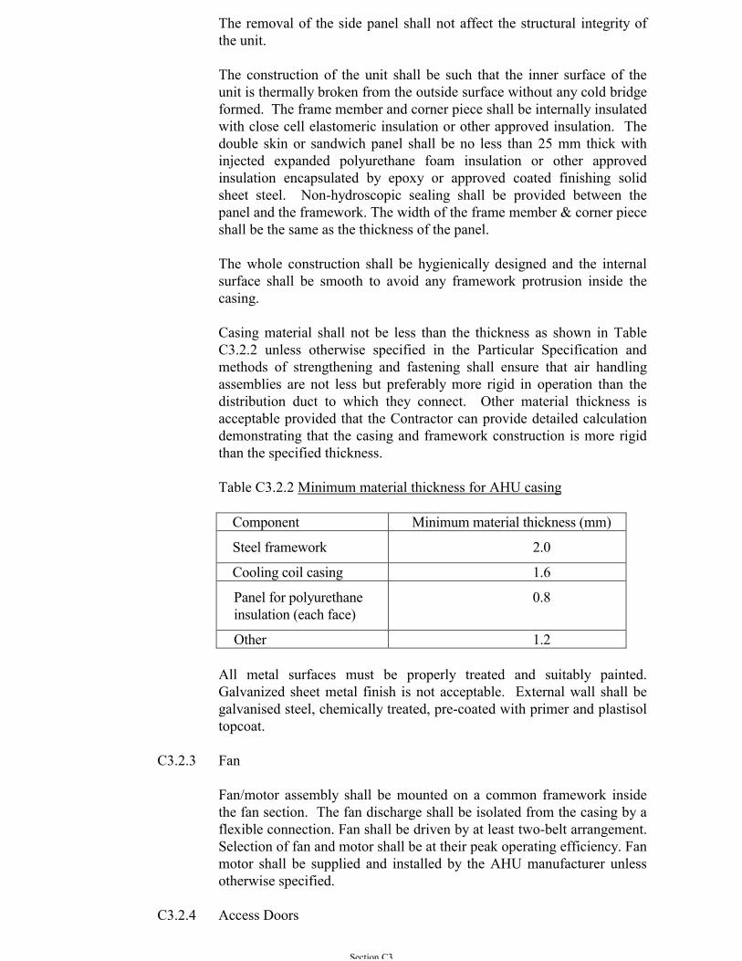
Casing material shall not be less than the thickness as shown in TableC3.2.2 unless otherwise specified in the Particular Specification andmethods of strengthening and fastening shall ensure that air handlingassemblies are not less but preferably more rigid in operation than thedistribution duct to which they connect. Other material thickness isacceptable provided that the Contractor can provide detailed calculationdemonstrating that the casing and framework construction is more rigidthan the specified thickness.
Table C3.2.2 Minimum material thickness for AHU casing
Component Minimum material thickness (mm)
Steel framework 2.0
Cooling coil casing 1.6
Panel for polyurethaneinsulation (each face)
0.8
Other 1.2
All metal surfaces must be properly treated and suitably painted.Galvanized sheet metal finish is not acceptable. External wall shall begalvanised steel, chemically treated, pre-coated with primer and plastisoltopcoat.
C3.2.3 Fan
Fan/motor assembly shall be mounted on a common framework insidethe fan section. The fan discharge shall be isolated from the casing by aflexible connection. Fan shall be driven by at least two-belt arrangement.Selection of fan and motor shall be at their peak operating efficiency. Fanmotor shall be supplied and installed by the AHU manufacturer unlessotherwise specified.
C3.2.4 Access Doors
Section C3
These shall generally be as detailed for acoustically treated doorsdescribed in the relevant content of Section C8. They shall also meetwith the insulation requirements stated in the relevant content of SectionB11 & C11. The access doors shall be 600 mm wide and vertically sizedfor the full height of the unit or 600 mm wide by 1500 mm high wherethe unit height exceeds 1500 mm. Quick access doors shall be providedfor filter section, coil section, transfer section, humidifying section,damper section, etc. Heavy duty double hinges and two quick releasefasteners shall be provided for all quick access doors.
Where return or fresh air ductwork connects to air handling units, accessto the filters shall be through side access panels at the filter chambers.
C3.2.5 Component Separation
Sections of packaged units shall be arranged with adequate separation toavoid re-evaporation of condensate from the cooler by any heating coilsinstalled to generally promote even air distribution across the face of allcomponents and to allow better access for maintenance.
C3.2.6 Anti-Corrosion Treatment
Where units incorporate humidifying plant and/or cooler batteries, theinternal surfaces of the units liable to be affected by moisture shall be ofnon- ferrous materials or galvanized mild steel sheet. The G.I.metalsheets shall be protected by at least two coats of anti-corrosion epoxyresin paint, colourcoat, or other approved finish applied in the factory.Field painting after the installation is not accepted.
Note : Colourcoat, a plastic coated steel panel, has a life expectancy inexcess of 40 years in normal environments. The coating is tough andscratch resistance and is applied over a PRIMER and GALVATITEsubstrates for even better corrosion resistance.
C3.2.7 Thermal and Acoustic Insulation
The unit shall be cold bridge free without sweating even under ambientconditions of 35oC and 98% RH. Thermal insulation shall be expandedpolyurethane foam or other approved material having a thermalconductivity not greater than 0.02 W/moC rated at the operatingtemperature. The insulation shall provide a high degree of noiseattenuation. Insertion loss through the panels shall be sufficient toachieve a 25 dB and 27 dB reduction at 63 Hz and 125 Hz octave bandsrespectively.
Insulation of sufficient thickness not less than 25 mm shall be selectedand applied to prevent surface condensation at design conditions and tominimize noise attenuation. Thermal insulation shall be securely fixed toor built into all sections of plant and equipment handling heated orcooled air. Where appropriate, a vapour barrier shall also be provided.Thermal and/or acoustic insulation characteristics and fixings shall be inaccordance with Sections B11 & C11 and B8 & C8.
Section C3
Particular care shall be taken to ensure surface protection of internalinsulation in areas where free moisture may be present and to avoiddamage in sections having walk-in access. Adequate lighting completewith door operated switch equipped at the factory shall be provided forAHUs with handling capacity greater than 5 m3/s.
C3.2.8 Air Filters
The filter section shall be provided by the air handling unit manufactureror specialist manufacturer of filter holding frame approved by theArchitect. The construction of filter section shall comply with therequirements of Sub-section C3.2.2 and shall ensure that there will not bebypass of un-filtered air. The filter section consisting of the filterelements and the filter fixing frames must have a positive means ofsealing off the unfiltered air by-passing the filter elements.
Intermediate bag filter or HEPA filter with 50 mm thick permanentwashable pre-filter shall be provided. HEPA filter and bag filtercartridges shall be mounted on non-corrosive aluminium or stainlesssteel tightness proof holding frame for side service or front releasedepending on the restriction of access. Neoprene gaskets shall beprovided along the contact surfaces of the filter element and the holdingframe. Filter cartridges shall be clamped against the slide rails withspring type clamping devices. The spring clamping devices shall bereleased by a single acting pneumatic cylinder for insertion or removal ofthe filter elements.
A test groove shall be provided on the filter seat of the holding frame ofeach filter element with a testing port for the connection to a portabletightness testing device provided by the Contractor. The portabletightness testing device shall comprise the followings :
(a) A volumetric flow meter to measure leakage flow rate from0.01 to 0.15 l/min.
(b) A volumetric flow meter to measure leakage flow rate from0.15 to 1.5 l/min.
(c) Hand-pump.
(d) Connection for external compressed air system (max. 1.1bar).
(e) Pressure gauge for hand-pump and external system.
(f) Connection tube linking the testing device and the tightnessproof frame.
(g) Throttle valve.
Section C3
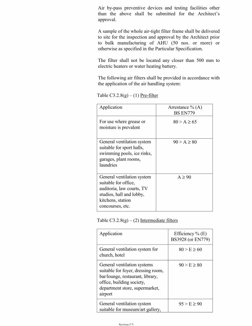
Air by-pass preventive devices and testing facilities otherthan the above shall be submitted for the Architect’sapproval.
A sample of the whole air-tight filter frame shall be deliveredto site for the inspection and approval by the Architect priorto bulk manufacturing of AHU (50 nos. or more) orotherwise as specified in the Particular Specification.
The filter shall not be located any closer than 500 mm toelectric heaters or water heating battery.
The following air filters shall be provided in accordance withthe application of the air handling system:
Table C3.2.8(g) – (1) Pre-filter
Application Arrestance % (A)BS EN779
For use where grease ormoisture is prevalent
80 > A ≥ 65
General ventilation systemsuitable for sport halls,swimming pools, ice rinks,garages, plant rooms,laundries
90 > A ≥ 80
General ventilation systemsuitable for office,auditoria, law courts, TVstudios, hall and lobby,kitchens, stationconcourses, etc.
A ≥ 90
Table C3.2.8(g) – (2) Intermediate filters
Application Efficiency % (E)BS3928 (or EN779)
General ventilation system forchurch, hotel
80 > E ≥ 60
General ventilation systemssuitable for foyer, dressing room,bar/lounge, restaurant, library,office, building society,department store, supermarket,airport
90 > E ≥ 80
General ventilation systemsuitable for museum/art gallery,
95 > E ≥ 90

Section C3
computer room.
General ventilation systemsuitable for hospital, researchlaboratory
E ≥ 95
Table C3.2.8(g) – (3) High efficiency and HEPA filter
Application Efficiency % (E)BS3928 (or EUROVENT4/4 & 4/5)
Special ventilation systemsfor hospital, clean room,research laboratory
99.999 > E ≥ 95
The quantity of spare filter shall refer to Sub-section C1.14.
C3.2.9 Air Cooling Coils
(a) General
Cooling coils shall be mounted on non-corrosive aluminiumslide rails. Coil sections shall be arranged to provideremoval of coils from the access side of the section. Aircooler casings shall be of galvanized sheet steel not less than1.60 mm thick with flanged ends drilled and corrosiontreated to receive counter flanges on connecting ductwork orother associated equipment. The bottom of casings shall bemade in the form of a watertight drip tray from AmericanIron Steel Institute 316 stainless steel after manufacture.Water shall not be carried over from a cooling coil into theremainder of the system and an eliminator section shall beprovided, wherever necessary or indicated. The drip trayserving the cooling coil shall be extended or a separate traybe provided to collect water from the eliminator. Drip traysshall be sloped towards a bottom drain connection andpipework shall be installed from each connection to thenearest sump or gully. The drain tray shall be accessible forcleaning without the coil having to be removed. The drainpipework shall include a water seal of adequate depth toprevent entry or exit of air to or from the system. A separatedrip tray shall be provided for each 1.2 m depth of coil. Onstacked coil, intermediate drain troughs shall be provided.All drip trays shall be adequately insulated with durable,non-smell and non-peeling under cooling/heating and airflow design conditions. Sealing devices shall be provided attops and bottoms of coils to minimize air by-pass and watercarry-over.
Section C3
Cooling coils shall utilise the full unit available crosssectional area. Cooling coils shall be constructed from oneof the following combinations: -
(i) Copper tubes expanded into aluminium fins.(ii) Copper tubes expanded into copper fins.(iii) Tinned copper tubes expanded into aluminium fins.(iv) Copper tubes expanded into tinned copper fins. (v) Copper tubes expanded into plastic coated aluminium
fins.
Tube thickness shall not be less than 0.45 mm. Fin thicknessshall not be less than 0.24 mm with suitable fin spacing.
(b) The resistance to airflow through a cooler battery shall notexceed 125 Pa taking into account the wet air condition. Theface velocity of airflow shall not exceed 2.5 m/s.
(c) Air cooling coils shall be supported such that their weight isnot transmitted to ductwork and they can be removed withoutdisturbing adjacent ductwork. Access doors with air sealsshall be provided on both the upstream and downstream ofthe cooling coils and shall be sized for the full height of theconnecting ductwork but need not exceed 1800 mm.
(d) Before leaving the manufacturer’s works cooling coils shallbe proof tested at 26 bar and leak tested at 17 bar.
(e) The number of rows of coil for primary air handling unitshall not less than eight rows and for other air handling unitsshall not less than six rows. Details performance calculationwith safety margin shall be submitted for Architect’sapproval for coil row less than the above specified
C3.2.10 Chiller Water Connections to Cooling Coils
The flow and return connections and headers shall be made of heavygauge seamless flanged copper tube. Provision shall be made for thermalexpansion of the tubes, for effective venting of the coils and theirconnections and for the draining of the headers and tubes.
Coil connections shall be arranged so as to enable same side connectionsto the flow and return pipework, and to have the supply and returnconnections to headers to give counter flow of air and water. Equal flowof water shall be through all the tubes in the coils.
(a) Up to and including 50 mm bore connections may be madeusing ground-in spherical seated unions. Pipework of 65 mmbore and above shall be connected using flanged joints.Isolating valves shall be provided on flow and returnconnections and arranged so as to facilitate easy removal ofthe cooler.
Section C3
(b) For rigidity, the short pipe length connecting the copper coilheader and the external G.I. or black steel pipe work shall bestainless steel pipe having the same bore size as the copperheader.
C3.2.11 Hot Water and Steam Air Heating Coils
(a) General
Casings shall be of galvanized sheet steel not less than 1.60mm thick with angle framing at each end drilled ready toreceive the counter flanges on the connecting ductwork.Heaters shall be supported so that their weight is nottransmitted to ductwork and so that they can be removedwithout disturbing adjacent ductwork. Access doors with airseals shall be provided on both the upstream and thedownstream sides of the heating coils and shall be sized forthe full height of the connecting ductwork of AHU sectionbut need not exceed 1800 mm.
(b) The heating coil shall be of one of the following types asindicated :
(i) Copper tubes with non-ferrous fins, fitted into copperor bronze headers.
(ii) Copper tubes with non-ferrous fins, fitted into steel orcast iron headers.
(iii) Mild steel tubes with mild steel fins, fitted into steelheaders, the whole protected against corrosion.
(c) The performance of heating coils shall be as indicated andthe method of testing for rating of the coils shall be inaccordance with BS 5141 Part 2.
(d) For C3.2.11(b)(i) and (ii) above, the copper tubes shallcomply with the test requirements as specified in BSEN1057, and the secondary extended heating surface shall beof either aluminium or copper as indicated. ForC3.2.11(b)(iii) above, the steel tubes shall comply with therequirements of BS 1387 (or ISO65). The secondary heatingsurfaces shall in all cases be in continuous mechanicalcontact with the primary heating tubes.
(e) The flow and return headers shall be arranged to ensure anequal flow of water through each tube. For pressures up toand including 350 kPa, connections of 50 mm bore andbelow shall be made to heater coils using ground-in sphericalseated unions. The connections to heating coils of 65 mmbore or greater, and for all sizes where the pressure exceeds350 kPa, shall be flanged. Provision shall be made forthermal expansion of the tubes, for effective venting of the
Section C3
coil and connections and for draining. Isolating valves shallbe provided on inlet and outlet connections, arranged tofacilitate easy removal of the heating coil. On any systemwhere the air static pressure at the heater exceeds 500 Pacover boxes shall be provided over the headers and bends, tominimize air leakage.
(f) The resistance to airflow of the heating coil shall not exceed65 Pa and the face velocity shall not exceed 4 m/s.
(g) Before leaving the manufacturer’s works the heating coilshall be tested with air under water to 1½ times the workingpressure or to 700 kPa, whichever must be the greater and atest certificate issued.
C3.2.12 Electric Type Air Heater Coils
(a) Electric air heaters shall consist of a number of sheathedheating elements of the enclosed type mounted in a sheetsteel casing. The elements shall be so installed that they canbe removed for cleaning or renewal without dismantlingductwork. The surface temperature of the elements shall notexceed 400oC when measured in an air flow of 2.5 m/s atambient temperature. A high temperature limit cut-outdevice with hand reset button shall be incorporated such thatthe limit device sensor is nearest to and above the heatingelements which are energized by the first control step. Thedevice shall operate within two minutes at a temperature of68.5oC.
(b) The control of electric air heaters, except for remoteboosters, shall be interlocked with the fan motor starters andan air flow control of the pressure or sail switch type so thatthe heaters cannot operate unless the fan is running.
(c) Electric air heaters which are installed as boosters in branchducts remote from the fans shall have an air flow control ofthe pressure or sail switch type which shall isolate theheating elements from the electricity supply in the event ofthe failure of air flow.
(d) The number of elements in the heater shall be the same as ora multiple of the number of steps in the controller. Allheaters and heater sections of more than 3 kW loading shallbe balanced over 3 phases and the complete heater bank shallbe arranged for balanced operation on a 3-phase 4-wiresystem.
(e) The connections from each element shall be taken to areadily accessible terminal box arranged for conduit entry.Each heater section shall be separately fused and the neutralpoint of all 3-phase star-connected sections shall be broughtout to a link in the terminal box. Near hot areas the wiring
Section C3
insulation shall be of a quality suitable for the maximumworking temperature.
(f) The total resistance of the heater to airflow shall not exceed15 Pa and the face velocity shall not exceed 6 m/s.
Note for energy efficiency design: Heating by hot water from waste heatreclaim or from heat pump system aiming for high operating efficiencyshould be considered. The detail of the heating battery is as shown inSub-section C3.2.11 above and the requirement shall be as described inthe Particular Specification to suit the system design.
C3.2.13 Humidification Equipment
Steam humidifiers shall be used. They shall be of the steam injectiontype using electric elements/electrodes or be of the evaporative pan typewith a minimum efficiency of 95%. Steam available from a central plantmay also be used.
It shall be possible to isolate the electrical supply from theelements/electrodes and they shall be arranged to facilitate removal formaintenance and replacement. Electric heating elements shallincorporate a high temperature cut-out and shall be interlocked to breakthe electrical circuit on low water level. Steam injection distributionpipes shall be provided for condensate return and be so designed andinstalled that free moisture is not carried over into the air stream. Steamgenerating equipment, other than remote central plant, shall be anintegral part of a purpose-made humidifying unit and shall incorporateautomatic water-level control, overflow protection and drainconnections. Automatic intermittent or continuous blowdown shall beincorporated as appropriate.
The evaporative pan type humidifier shall be positioned so that it is notaffected by the radiant heat from heater batteries.
C3.2.14 Additional Modular Sections
Additional modular sections shall be provided with ease for theaccommodation of ultra-violet steriliser, heat wheel or other devices asspecified for the improvement of air quality and energy efficiency.
C3.3 AXIAL FLOW FANS
C3.3.1 Axial flow fans shall be of either the single-stage type or the multi-stagecontra-rotating type with each impeller mounted on an independentmotor.
C3.3.2 Casing shall be rigidly constructed of mild steel stiffened and braced toobviate drumming and vibration. Cast iron or fabricated steel feet shallbe provided where necessary for bolting to the base or supports. Inletand outlet ducts shall terminate in flanged rings for easy removal.
Section C3
C3.3.3 The length of the duct casing shall be greater than the length of the fan(s)and motor(s) in order that the complete section may be removed withoutdisturbing adjacent ductwork.
C3.3.4 Electrical connections to the motor(s) shall be through an externalterminal box secured to the casing.
C3.3.5 Impellers shall be of galvanized steel or aluminium alloy; the blades shallbe secured to the hub or the blades and the hub shall be formed in onepiece. The hub shall be keyed to a substantial mild steel shaft carried intwo bearings and the whole statically balanced. Unless otherwiseindicated blades shall be of aerofoil section.
C3.3.6 Where axial flow fans are driven by a motor external to the fan casingthe requirements of the relevant content in Sections B7 & C7 for pulleysand for V-belt drives and guards shall be met. Unless otherwiseindicated a guard is not required for any part of a drive which is insidethe fan casing. An access door of adequate size to facilitate inspection,cleaning and other maintenance shall be provided.
C3.3.7 Where axial flow fans of the bifurcated type are indicated the motorsshall be out of the air-stream and shall normally be placed between thetwo halves of the bifurcated casing in the external air. Where hot gasesor vapours are being handled the motor and the bearings shall be suitablefor operation at the temperature they may experience. The bifurcatedsection containing the motor shall be mounted vertically in order tomaximise convection air flow over the motor.
C3.4 CEILING FANS
C3.4.1 Dimensions
The sweep diameter of the units shall be 1200 mm or as otherwiseindicated.
C3.4.2 Capacity
The 1200 mm unit shall be capable of an air delivery of 3.9 m3/s or asotherwise stated.
C3.4.3 Duty
(a) The unit shall be suitable in all respects for operation underambient air conditions of 40°C and 95% RH.
(b) The unit shall be suitable for operation in 220 V, 50 Hzsingle phase AC mains.
(c) The unit shall be designed for heavy duty commercial anddomestic usage.
Section C3
(d) The fan shall operate without generating unnecessary noise atall speeds.
C3.4.4 Motor
(a) The motor shall be a totally enclosed, capacitor run inductionmotor, with internal stator and external squirrel cage rotor.
(b) The rotor shall be mounted in grease lubricated ball bearings.
(c) The power factor shall not be less than 0.85 at any speed.
(d) The motor shall be rated for continuous operation underambient air conditions of 40°C and 95% RH and thetemperature of the windings shall not exceed 50°C after two(2) hours of continuous operation.
(e) All electrical components, cables etc. shall conform to theappropriate specifications or shall be of fully equivalentquality and capacity.
C3.4.5 Blades
(a) The fan shall be fitted with three (3) blades. "Twisted"blades are preferred.
(b) The blade assemblies shall consist of blades manufacturedfrom heavy gauge aluminium securely riveted to steel bladecarriers.
(c) The blade carriers shall be manufactured from mild steelplate of not less than 3 mm in thickness and of not less than40 mm width at the narrowest point, pressed to shape.
(d) Where the blade carriers are twisted to give the requiredangle of incidence to the blades, there shall be large radiusbends to prevent stress concentrations in the blade carriers.
(e) Anti-vibration bushes shall be installed between the bladesand blade carriers.
(f) The blade carriers shall be securely fastened to the frame ofthe motor by machine screws and spring washers, the wholeassembly shall be designed and constructed to ensure thatthere is no possibility of a blade becoming detached duringoperation.
C3.4.5 Terminals and Capacitor
(a) The plastic terminal block and capacitor shall be mounted ina ferrous metal connecting piece, located between the fan andthe down-rod. The leads from the stator windings shall beconnected to the terminal block. An earthing terminal,
Section C3
consisting of a round head brass, screw and washer, shall beprovided on the connecting piece. All exposed metal parts ofthe fan unit shall be connected to this earthing terminal.
(b) The bottom portion of the connecting piece shall be screwedon to the shaft of the motor. The connecting piece shall betightened onto a shoulder formed on the motor shaft. A 4mm minimum thickness steel hexagonal lock-nut with lockbracket underneath shall then be fitted and tightened inposition. The connecting piece shall additionally be screwedin the fully tightened position by two hardened steel grubscrews. These screws shall engage in shallow depressionsdrilled in the shaft after the connecting piece has beentightened in place to ensure positive locking.
C3.4.7 Down-Rod Assembly
(a) The down-rod assembly shall consist of a down rod and asteel shaft with a hard rubber roller for suspension of the fan.The down rod shall be supplied to the length indicated for thejob which shall be measured from the top of the connectingpiece to the centre of the pin in the shackle at the top.
(b) The down-rod shall be manufactured from 12 mm borestandard mild steel pipe of not less than 3 mm wall thickness,having an external diameter of approximately 20 mm. Itshall be accurately threaded at one end and shall be screwedinto the top portion of the fan connecting piece (capacitorhousing) from which it shall protrude by a minimum of 2mm.
(c) It shall be locked in position by two hexagonal steel lock nuts,having a minimum thickness of 6 mm, tightened onto theupper machined surface of the fan connecting piece.
(d) The down-rod shall also be locked to the fan connectingpiece by means of a steel split-pin, of not less than 5 mmdiameter, passing through both the fan connecting piece andthe down-rod.
(e) The split-pin holes in the fan connecting piece shall be ofsuch a diameter that the split-pin is a light push fit there-in.The matching split-pin holes in the down-rod shall be justsufficiently large so that the split-pin shall be a light push fit,when the hole is in its worst position relative to thethreading. All burrs and sharp edges shall be removed fromthe split-pin holes both in the fan connecting piece and thedown-rod.
(f) The steel suspension shackle shall be welded to the down-rod. Welding shall be of good quality and to the satisfactionof the Architect. The rubber roller shall be mounted on an 8mm diameter steel clevis pin secured by a split-pin.
Section C3
(g) The ends of the down-rod shall be rounded off and free fromburrs. There shall be no sharp edges which could causedamage to the insulation of the wiring.
C3.4.8 Suspension Joints and Threaded Parts
(a) Joints along the suspension rod must be of double-lockingdesign, i.e. at least two independent positive locking devicesmust be employed to prevent a joint from loosening itself.
(b) The maximum clearance between threaded mating parts mustnot exceed 1% of their mean diameter.
(c) The direction of rotation of the fan shall be such that allscrew joints tend to be tightened when the fan is in operation.
C3.4.9 Canopies
Two canopies manufactured from plastic or pressed steel sheet shall beprovided and fitted over the upper and lower ends of the down-rod. Theyshall be fixed to the down-rod grub screws.
C3.4.10 Balance
(a) All fans shall be fully balanced after assembly, with anynecessary adjustment being made to ensure that they shall notoscillate due to out-of-balance forces.
(b) All blades shall be given a single identification number, orletter, permanently stamped on the supply side, with acorresponding mark stamped on the motor body so that thefan blades may be reassembled in the correct position.
C3.4.11 Finish
The whole fan shall be finished in high quality stove-enamel, white,ivory or other colour where required by the Architect.
C3.4.12 Speed Regulator
(a) The speed regulator shall be of the choke type with five (5)speed and an "OFF" position, built on a moulded plastic, orinsulated steel base and enclosed by a moulded plastic cover.The cover shall be white or ivory or other colour to match thefan.
(b) An earth terminal shall be provided on the base with an earthwire permanently connected to the steel core of the chokeunit.
(c) The speed regulator shall move smoothly and easily betweenpositions.
Section C3
C3.4.13 Inspection
At least one typical unit for those to be supplied for a given Contractshall be submitted for an acceptance test carried out for the Architectbefore delivery of any quantity is made to the Contract Site.
The test units shall be provided and collected by the Contractor at noextra cost to Architect.
C3.5 CENTRIFUGAL FANS
C3.5.1 Centrifugal fans for high-velocity high-pressure systems as definedwithin HVCA Standard DW/144, shall be of the backward bladed type.
C3.5.2 Centrifugal fans with motor brake power of 7.5 kW or more shall be ofthe backward bladed type having a fan total efficiency not less than 75%.
C3.5.3 Fan casings shall be constructed to permit withdrawal of the fan impellerafter fan installation. Fans other than those in factory constructed airhandling units (AHUs) shall be provided with flanged outlet connectionsand spigoted inlet connections suitable for flexible joint connectionsexcept those for use with negative pressures greater than 500 Pa in whichcase inlet connections shall be flanged.
C3.5.4 All fan casings of 900 mm diameter or greater shall be provided withremovable access panels which shall incorporate purpose-made air seals.The sizes of access panels shall be such as to facilitate cleaning andmaintenance of the impeller and shall not be less than 600 mm X 600mm.
C3.5.5 For all kitchen extract ventilation fans an access door, for inspection andcleaning, shall be fitted to the scroll casing in an accessible position; itshall be of full width of the impeller. A plugged drain point shall befitted at the lowest point of the fan.
C3.5.6 Permanent indication shall be provided to show the correct direction ofrotation of the fan impeller.
C3.5.7 Impellers shall be of galvanized steel or aluminium alloy whereindicated, of riveted or welded construction, with spiders or hubs ofrobust design, and shall be capable of running continuously at ten percent in excess of normal speed. Impellers shall be keyed to a substantialmild steel shaft and the impeller complete with shaft shall be staticallyand dynamically balanced and tested for satisfactory overspeedperformance before leaving the maker's works.
C3.5.8 Fan shaft shall enable pulley to be mounted at both ends. Shaft bearingsof belt driven single inlet fans shall be truly aligned and rigidly mountedon a pedestal common to both bearings. Double inlet, double width fansshall have a pedestal mounted bearing at each side of the fan. Fanbearings shall be of the ring oiling sleeve type, or the ball or roller type.
Section C3
Where silence is important the bearing pedestal shall not be attached tothe fan casing, instead ring oiling sleeve type bearings shall be supplied.
C3.5.9 Centrifugal fans shall be driven by electric motors through V-belt drivescomplying with the relevant content in Sections B7 & C7.
C3.5.10 Single phase powered variable flow centrifugal fans where specifiedshall be fitted with variable inlet vanes which shall be matched to the fanperformance to give stable control. Vanes shall be closely interlocked toensure movement in unison. Operation shall be manual or automatic asindicated. Where manual control is indicated, the operating device shallfacilitate positive locking in at least five different positions. Vane bladesshall not vibrate or flutter throughout their operational range.
C3.5.11 Three phase powered variable flow centrifugal fans where specified shallbe variable speed driven. Variable speed drive shall be in accordancewith Sections B7 & C7 of this General Specification.
C3.6 FAN COIL UNITS
C3.6.1 General
Fan coil units shall comply with quality standard ISO9001/9002 and be'type' tested. The Contractor shall submit the make and type of each fantogether with the 'type' test certificate for the Architect's approval. Theorigin of the fan shall be from the country where the 'type' test wasconducted.
Fans, filters, cooling coils, heating coils, motors, thermal and acousticinsulation shall comply with the appropriate sections of this GeneralSpecification and the following requirements:-
(a) Fans shall be of the Double Inlet Double Width (DIDW)forward curved centrifugal or tangential flow types and shallbe of mild steel, aluminium, reinforced glass fibres or rigidplastic material as specified in Particular Specification.
(b) Air filters shall be as indicated in the relevant content ofSection C1 but with an efficiency of not less than 50% whentested in accordance with BS EN779.
(c) Motors shall be quiet running and have sleeve or ballbearings factory lubricated for life. Motor windings andelectrical components shall be impregnated or protected toavoid trouble from condensation. The fan motor shall be ofthe single phase permanent split capacitor type provided withthree speed tapped windings.
(d) All fan coil units capacity and air flow rate shall be selectedbased on the performance of the units at medium fan speed.
Section C3
(e) In selecting the fan coil units, allowance shall be made forthe actual resistance imposed on the air flow of the units dueto ducts and grilles. The added resistance is to be applied toall fan coil units whether shown to have ducts connected ornot, and shall be taken as not less than 50 Pa external to theunit.
The thermal, volumetric and acoustic performance of fan coil units shallmeet the requirements indicated and testing and rating shall be inaccordance with BS 4856.
3.6.2 Casings
Casings shall be of G.I. sheet metal with thickness not less than 1.0 mmsuitably stiffened to minimize drumming and vibration and shall beprotected against corrosion and finished inside and outside with stovedprimer. All corners shall be rounded off without sharp edges. Casingsshall be lined with material to act as both thermal and acoustic insulationwhich shall comply with the relevant of Sections B11, C11, B8 & C8.Casings shall include space for pipework connections and valves, andthere shall be ready access to the fan and motor, filter, damper, drain pan,pipework connections and valves, for maintenance purposes.
The motor and fan shall be mounted on a detachable mounting chassisthat can be removed from the fan coil enclosure as one assembly (withextended cables) to facilitate fan and motor cleaning. It shall then alsobe possible to remove the fan impeller scroll casing in order to properlyclean the fan blades. Fan and motor assemblies shall be complete withneoprene rubber anti-vibration mountings.
C3.6.3 Coil
(a) Cooling coils shall be minimum two-row and shall includean air vent cock and drain valve.
(b) The chilled water cooling coil shall be ARI certified andconstructed from seamless copper tubes mechanicallybonded to aluminium fins.
(c) Each coil shall be provided with motorized 2-way solenoidcontrol valve and isolation valves. Flexible pipe connectorscomplete with union joints to facilitate removal of the entireunit shall be provided. The connector shall be stainless steelbraided polymer tubing limited to 300 mm long and suitablefor the system pressure.
(d) Working pressure of coils shall suit specific requirements.
C3.6.4 Components
(a) All units shall include an easily removable filter capable oftreating the total air volume. Filters shall, unless otherwise
Section C3
specified, be washable. It shall be supported in a stiffaluminium/stainless steel withdrawable frame.
(b) Drain pans shall be made of one piece stamped stainlesssheet steel with no weld and protected against corrosion, ormade of plastics or reinforced glass fibre materials insulatedwith a minimum of 13 mm thick flexible closed cellelastomeric insulation. Drain pans shall be large and deepenough to collect all condensate from the coil, return bendsand pipework connections. The pan shall be removable andhave a slight fall to the drain connection. For units whoseloads include a high proportion of latent cooling the fall tothe drain point and the size of the drain connection shall beadequate to deal with the condensed moisture.
C3.6.5 Arrangement of Units
The arrangement of units (e.g. wall, floor or ceiling mounted), theposition of inlet and outlet grilled if any, the need for G.I. sheet metalcasing etc. shall be as indicated.
C3.6.6 Controls, Dampers and Grilles
Fan coil units shall have a combined room temperature sensor completewith 3-speed controller and heating/cooling mode selector as specified.Where indicated they shall have connections for both fresh andrecirculated air and shall include a damper which shall be adjustable togive up to 25% of the fan capacity drawing from the fresh air source.Outlet grilles shall be capable of adjusting the direction of airflowwithout adversely affecting pressure drop. On floor mounted units,supply grilles shall be on the top of the unit.
C3.6.7 Noise level
The noise data provided shall include an octave band analysis of thesound power level of each unit when operating at its full or the stateddesign speed.
C3.6.8 Electric Heaters for Fan Coils
Electric heaters shall be of maximum 2 kW capacity of the black heatsheathed element type, plain or finned, and shall be provided with asafety cut-out thermostat set to operate at 50oC.
Sail switch is to be fitted for each heater battery and is to be connected inseries with the safety cut-out thermostat to switch off the heater in theevent of reduced air flow.
The mounting, arrangement and terminals etc. for Electric Duct Heatersshall be in accordance with Contract Drawings or other installationstandard approved by the Architect.
Section C3
C3.7 CASSETTE TYPE FAN COIL UNITS
C3.7.1 Generally, the cassette fan coil units shall comply with Sub-section C3.6of this General Specification.
C3.7.2 The fan coil unit shall be of integrated cassette type which combines thesupply air slot, return air grille, fan, casing, cooling coil, heating coil orelectric heater (if required) into a single unit. No connection of ductworkis allowed except for fresh air.
C3.7.3 Fan coil units shall be selected at design duty and specified noise levelwith fan running at medium speed.
C3.7.4 Each fan coil unit shall be provided with a combined room temperaturesensor complete with 3-speed controller and heating/cooling modeselector as specified. Remote control unit shall be provided as specified.
C3.7.5 Air cooling coil shall be constructed with copper tubes and shall bearranged horizontally. Tubes shall have brazed copper return bends. Finsshall have smooth drawn collars of length equal to fin spacing andmechanically bonded to tubes. Fins shall be of the plate type, corrugatedto ensure maximum air contact. All coils shall have an air release valveand a drain valve. Working pressure of coil shall be of a minimum of1200kPa and to suit system pressure design. Connection of water pipingshall refer to Sub-section C3.6.3(c).
C3.7.6 Each fan coil unit shall be provided with a stainless steel drain pansituated beneath the cooling coil and arranged so that all moisture willcollect in and drain from the pan. Drain pans shall be insulated externallywith a minimum of 25 mm approved type foamed plastic. Each drain panshall be fitted with a drain pipe which shall be connected via suitableruns (correctly laid to fall) to the drainage system. Drain pans shall havecopper male connectors for connection to the condensate drain. Theconnector shall be positioned to ensure rapid discharge of moisture fromthe pan.
C3.7.7 Built-in condensate pump shall be provided for the removal ofcondensate. A water sensing system with low, high and warning limitsshall be provided which actuates the running of condensate pump at highwater limit and trigger the alarm system at warning level. When waterlevel reaches the warning limit, the sensing system shall cut off the unitoperation. An alarm signal shall be given locally. The signal shall beconnected to CCMS or remote indication system as specified.Condensate pump shall be designed to run continuously at some essentialareas as specified. The power source for condensate pump and theassociated control system shall be independent from that of the fan coilunit such that the pump can still be operated after the units has beenswitched off.
C3.7.8 The filter media shall be of the washable type and shall be enclosed in aone-piece formed stainless steel frame with covers flush mitred andreinforced by a die-formed inverse bead.
Section C3
C3.7.9 Fan shall be of the quiet running direct driven centrifugal type withaluminium blades mounted to a solid steel shaft. Fan motors shall be ofthe ‘split capacitor’ type suitable for single phase electrical supply. Themotor shall be resiliently mounted to the fan tray or scrolls. Themotor/fan tray assembly itself shall also be resiliently mounted to thecasing structure.
C3.7.10 Manually adjustable louvres for directional airflow shall be provided forsupply air slot in each fan coil unit. Options shall be given to choosefrom 2-way, 3-way or 4-way supply air discharge.
C3.8 IN-LINE CENTRIFUGAL AND MIXED FLOW FANS
Mixed flow fan casings shall be rigidly constructed of mild steel, or aluminiumalloy stiffened and braced where necessary to obviate drumming and vibration.Mounting feet shall be provided where necessary for bolting to a base or supports.Inlet and outlet shall terminate in flanges to facilitate removal. Stator vanes shallbe of mild steel or aluminium alloy. The unit shall be designed to facilitate accessto the impeller. Where motors are mounted external to casings, drives and guardsshall be provided in accordance with Sections B7 & C7. An access panel withpurpose-made air seal shall be provided in the fan casing; the access panel shall besized and so positioned as to facilitate maintenance.
C3.9 MECHANICAL ROOF EXTRACT UNIT
The fans used in roof extract units shall meet with the appropriate requirements ofthe preceding content relating to fans generally and in particular to the types of fansinvolved. The materials of cowls and bases shall be resistant to weather, solarradiation and appropriate to the location of the unit and type of fan installed.Casings shall be formed to facilitate a weatherproof fixture to the buildingstructure. Adequate access to electrical supply terminals and lubrication pointsshall be provided by means of hinged cowls or otherwise as appropriate. Back-draught dampers and/or fire release dampers shall be provided where indicated.Bird entry preventive guards of not greater than 25 mm mesh shall be provided asan integral part of the unit.
C3.10 PROPELLER FANS
Impellers shall be of steel or aluminium; the blades shall be fastened to the hub orthe blades and hub shall be formed in one piece. The bearings may be ball, roller,or sleeve type. Propeller fans may be ring mounted, diaphragm mounted ordiaphragm mounted in a casing, as indicated.
The tip speed of propeller fans shall, unless otherwise indicated, not exceed 20 m/s.All ring mounted propeller fans which are exposed, i.e. not installed within aductwork or other enclosure, shall be adequately protected by safety guards.
Section C3
C3.11 PROTECTIVELY COATED FANS AND FANS FOR CORROSIVE ORHAZARDOUS APPLICATIONS
Where fans are required to handle toxic, corrosive, flammable, explosive or hightemperature gases. The materials and form of construction shall be selected and suitthe particular application. Bearings and lubrication arrangements shall be suitablefor the conditions. Protectively coated fans shall meet with the appropriaterequirements of the previous content relating to fans generally and to particulartypes of fans; the form of protection shall be as indicated. Where a protectivecoatings is required for use with corrosive gases the coating shall cover all parts ofthe complete fan, motor and casing assembly which will be in contact with thecorrosive gases. No fan shall be installed if the protective coating has beendamaged in any way. Impellers shall be of coated steel, stainless steel, aluminiumor fire-proof plastic as indicated.
Where fans are installed in a potentially explosive atmosphere the specialrequirements will be indicated in the Particular Specification and are to be rigidlyadhered to.
C3.12 ROTARY FANS (WALL OR CEILING MOUNTED)
C3.12.1 Capacity
The unit shall be capable of an air delivery of not less than 1.1 m3/s.
C3.12.2 Dimension
The blade sweep diameter of the unit shall be 400 mm.
C3.12.3 Duty
(a) The unit shall be suitable in all respects for operation in ambientair conditions of 35°C and 95% RH.
(b) The unit shall be suitable for operation on 220 V, 50 Hz, singlephase AC supply.
(c) The fan shall not require periodic lubrication.
C3.12.4 Construction
(a) These units shall be of deluxe and pleasing appearance withsmooth safe edges and of "easy-to-disassemble" design forcleaning. Units not considered of suitable appearance may berejected by the Architect.
(b) The fan shall have high quality aluminium or plastic blades.
(c) The fan shall be fully balanced after assembly.
Section C3
(d) The blades shall be enclosed by a high quality chromium platedmetal wire-mesh metal guard. The gap in between the guardwires shall not be greater than 15 mm at any point.
(e) The fan shall be provided with rotary mechanism for a rotationalsweep of 360° when mounted on the ceiling for rotary ceilingfan or for a swing of 150o when mounted on a wall or columnfor rotary wall fan.
(f) The whole unit shall be finished to manufacturer's standard lightcolour or as otherwise approved by the Architect.
C3.12.5 Electrical
(a) All electrical components, cables etc. shall conform to theappropriate standards and specifications stipulated in SectionsB7 & C7.
(b) All exposed metal parts of the unit shall be suitably earthed viathe 3 core flexible cable.
(c) The fan shall be provided with speed regulator and be capable ofbeing switched on and off by a remote 5A switch.
(d) The fan shall be provided with an adequate length of 0.75 mm2 3core PVC insulated and sheathed flexible cable and connected tothe associated socket outlet. Where provided but not fixed, thecable provided shall be two meters in length.
C3.12.6 Inspection
As Sub-section C3.4.13.
C3.13 TERMINAL AIR CONTROL DEVICES
C3.13.1 General
(a) Terminal units shall be factory fabricated and tested inaccordance with British Standard BS 4979, BS 4954, BS4857 (or related content of ISO5220, ISO5221 and ISO5219)where appropriate.
(b) Casing of the unit shall be manufactured from galvanisedsteel sheet of minimum 0.7 mm thick having round edges toform a rigid construction.
(c) Noise including in-duct sound power level, which emittedthrough the unit casing shall not exceed the value asindicated and/or as stated in Section B8 & C8 of this GeneralSpecification.
Section C3
(d) The entire unit shall be internally lined with thermal andacoustic insulation in compliance with the relevant content inSections B11 & C11 and B8 & C8 enclosed in a galvanisedperforated metal liner. The lining shall be securely fixed andshall be proof against erosion by the air flow. The acousticand thermal insulation shall comply with NFPA-90A, UL-181 and BS 476 Part 4, 5, 6 & 7 standards (or the relatedcontent of ISOR1182, ISO5667, ISOTR5658-1, ISO10295-2& 10295-3) and the requirements of the Fire ServicesDepartment.
C3.13.2 Induction Units
(a) Filters, cooling coils, heating coils and thermal and acousticinsulation shall comply with the appropriate sections of thisGeneral Specification, with the following exceptions oralternatives :-
Air filters shall be as specified in Sub-section C3.6.1(b) forfan coil units.
Unless otherwise indicated, cooling coils and/or heating coilsshall be formed of copper primary surface tubes withaluminium secondary surfaces.
(b) Casings shall include space for pipework connections andductwork as necessary, and there shall be ready access to thefilter, the primary air nozzles and any valves and controls.
(c) Primary air plenums shall be treated with thermal andacoustic insulation which shall comply with the relevantcontent of Sections B11 & C11 and B8 & C8. Units shall becomplete with a suitable device to regulate primary airpressure and air volume flow rate. Primary air nozzles shallbe arranged to induce an even secondary circulation acrossthe cooling and/or heating coils. The unit air outlet shallincorporate means of directional control of air supply whereindicated.
(d) Cooling/heating coils shall include an air cock and shall beeffectively sealed to prevent air by-pass around the coil.Drain pans shall be of a material which is resistant tocorrosion or is protected against corrosion and shall have aslight fall to a drain connection.
(e) The arrangement of units (e.g. wall or ceiling mounted), andthe need for sheet metal casing shall be as indicated.
C3.13.3 Single Duct Constant Air Volume (CAV) Terminal Units
(a) Unit shall be constructed in accordance with Sub-sectionC3.13.2 where appropriate.
Section C3
(b) Units shall incorporate a self-acting constant flow ratedevice. The pressure drop across the unit at design airvolume flow rate shall not exceed 250 Pa.
C3.13.4 Single Duct Variable Air Volume (VAV) Terminal Units
(a) Unit shall be rated in accordance with ASHARE Standard36-72 and Air Diffusion Council Test Standard 1062R4. Theperformance data shall be certified by a recognizedlaboratory approved by the Architect.
(b) Unit shall be of the pressure independent type throughout theentire range and shall be capable of resetting the air flow to+5% of the nominal air flow regardless of the change in thesystem pressure.
(c) The unit shall be capable of being reset to any airflowbetween zero and the maximum catalogued air volumeautomatically to compensate for duct pressure fluctuation.
(d) The air velocity sensor shall measure the true velocity acrossthe inlet of the unit and be unaffected by changes in duct airtemperature and humidity. The sensor shall be fieldreplaceable without opening the associated ductwork.
(e) The entire package shall be calibrated and factory-set for themaximum and minimum flow rates as specified but shall becapable of easy re-adjustment in the field. Each terminal boxshall be provided with factory-calibrated, direct reading airflow indicator. Separate gauge taps shall be provided forfield re-calibration and commissioning.
(f) The velocity controller and the damper actuator shall be of anintegral unit directly mounted onto the damper shaft. Theactuator shall be capable of operating in the stalled positionwithout overheating or mechanical damage. Mechanicallimit switch will not be accepted. The damper shall remainin a fixed position when electrical power source isinterrupted. The control equipment must be easily accessiblethrough an access door provided with quick-release fasteners.
(g) The damper shall be made of heavy gauge galvanized steelwith peripheral gasket, pivoted in self-lubricating bearing. Inthe fully closed position air leakage past the closed dampershall not exceed 2% of the nominal catalogue rating at250 Pa inlet static pressure.
(h) VAV terminal unit shall be pneumatic, electronic or DDCcontrolled as specified. One thermostat shall be provided foreach VAV terminal unit unless otherwise specified. Thethermostat offered shall match the unit and includetemperature set point and velocity adjustment point locatedinside.
Section C3
The thermostat shall have a calibrated scale showing setpoint temperature with a constant approximately 1oCproportional band regardless of minimum and maximumvelocity settings. Air flow set point shall be adjusted byscrew and voltmeter tap in the thermostat or by otherapproved means for both high and low air volume limits.The location of the thermostat shall be determined on site.
(i) The unit shall not be selected at the top of the cataloguerange in order to ensure it meets with the specified roomnoise level requirement.
(j) Circular connection spigot of insertion dimensions, with selfsealing rubber gasket shall be provided at both the inlet andoutlet of the unit. Each multi-outlet section shall becomplete with at least one spare outlet, capped for future use.
(k) Unit shall be complete with a mixing attenuator sectionwhere specified.
The attenuator shall be factory-fitted to the basic unit and ofa length not less than 400 mm. The casing shall beconstructed as the terminal unit, but with acoustic insulationof mineral wool with a minimum density of 70 kg/m3.
(l) Unit shall be complete with electric heater section wherespecified. Heater casing shall be made of minimum 0.7 mmthick galvanized steel sheet insulated by 30 mm thickmineral wool lined with staple fibre fabric. The heater shallbe easily withdrawn from the casing for servicing andmaintenance. Heating element shall be of the shealth andblack heat type. The heater shall be controlled by contactorand step controller fully interlocked with a sail switch andduct type overheat thermostat with fail safe feature andmanual reset.
C3.13.5 Dual Duct Terminal Units
Dual duct terminal units shall be constructed as single duct CAV unitand VAV unit and shall incorporate devices for varying the proportionsof hot and cold air and for providing thorough mixing of the air.
C3.14 GRILLES AND DIFFUSERS
C3.14.1 General
(a) The grilles and diffusers shall be rated in accordance withASHRAE standard 36-72 and Air Diffusion Council teststandard 1062R4.
Section C3
(b) All grilles and diffusers shall have concealed fixing systemand shall have quick release frame to facilitate cleaning.
(c) All supply grilles and diffusers shall be mounted onsubstantial frame and shall be provided with soft rubber orfelt joining ring inserted under the frame to prevent airleakage and the formation of condensate on the fitting.
(d) All grilles and diffusers shall not be less than the sizeindicated; where no size is given they shall be capable ofhandling the air flows and distribution indicated withoutproducing unacceptable air flow noise. The Contractor shallselect the supply air grilles and diffusers to achieve good airdistribution and adequate air movement in the conditionedspace.
(e) In order for the ceiling grilles and diffusers to match with thefalse ceiling layout pattern, the actual size of the grilles anddiffusers shall be confirmed by the Architect before ordering.
For all grilles and diffusers which are smaller than the ceilingtile on which they are installed, they shall be located in thecentre of the ceiling tile. The exact location of the ceilinggrilles and diffusers shall be co-ordinated with other services.The Contractor shall confirm the exact location with theArchitect before works commence.
Where grilles and diffusers are to be incorporated into falseceilings before any grilles or diffusers are installed intoductwork or fan coils, the Contractor shall ensure that theBuilding Contractor marks out the ceiling line on theadjacent plastered walls or columns and also indicates whereceiling tee bars line up or the ceiling joints occur in orderthat such datum can be worked to.
(f) The finishing colour of the grilles and diffusers shall beapproved by the Architect as different colours may bespecified in different areas. The Contractor shall co-ordinatewith the Building Contractor and other specialist Contractorsespecially the ceiling and electrical Contractor for theintegration of the air diffuser into the ceiling and luminaire(for light troffer diffuser).
C3.14.2 Grilles
(a) Grilles shall be of steel, aluminium, PVC or as otherwiseindicated. Steel grilles shall be protected against rusting andsupplied in fully finished stove-enamelled or otherwisespecified condition.
(b) Each supply air grille shall have two sets of separatelyadjustable louvres, one set horizontal and one set vertical,and shall be complete with an opposed blade multi-leaf
Section C3
damper. Alternatively in lieu of the opposed blade multi-leafdamper a rhomboidal air controller may be provided; this aircontroller shall control both the volume of air passing andthe distribution of air across the grille face. The louvre andthe damper or air controller shall be adjustable from the frontof the grille. For up to ten grilles, one set of tools requiredfor adjusting the louvre and dampers or air controllers shallbe provided. From eleven to twenty-four grilles, two sets andabove twenty-five grilles, three sets of tools shall beprovided.
(c) Return air grilles shall have either a single set of louvre orbars (either vertical or horizontal) or a lattice, egg crate orexpanded metal front.
Each return air grille shall be complete with an opposedblade multi-leaf damper or a rhomboidal air controlleroperable from the front.
Where return air grilles are fitted for fan coil units, they shallbe arranged such that the central core of the grille is hingedand demountable for access to the filter for cleaning.Mounting frames for these grilles shall include provision forfixing the filter in position.
C3.14.3 Diffusers
(a) Diffusers shall be of steel or aluminium. Steel diffusers shallbe protected against rusting and shall be stove enamelled forfinished colour approved by the Architect. Diffusers shallincorporate an edge seal; diffusers mounted on ceilings shallhave anti-smudge rings. Pan type diffusers shall be providedexcept where cone type diffusers are indicated.
Diffusers shall be provided with volume control dampers ofthe iris, flap or sleeve type which shall be adjustable from thefront of the diffuser. Where the length of a vertical duct to adiffuser is less than twice the diameter of the diffuser anequalizing deflector shall be fitted.
The design of the supply air diffuser shall be capable toinduce adequate air movement and provide the throw tocover the entire air-conditioning space without causing airturbulence and cold draft.
(b) Linear diffusers shall be constructed of extruded aluminiumsection and include a control damper at the rear of the vanesgiving volume control down to complete shutoff andoperated from the face of the diffuser. Linear diffusers forsupply air shall have adjustable blades to give directionalcontrol of air flow. The linear diffuser shall be capable ofmaintaining a horizontal discharge pattern at a turn down
Section C3
ratio down to 20% of the maximum specified air volumewithout air dumping.
The linear diffuser shall be complete with factory fabricatedplenum with suitable inlet connection for flexible ductwork.The plenum and diffuser neck shall be constructed ofgalvanised steel sheets internally lined with 25 mm 48 kg/m3
glass cloth faced fibreglass insulation enclosed in galvanisedperforated metal liner.
The insulation shall comply with NFPA-90A, UL-181 andBS 476 Part 4, 5, 6 & 7 standards ( or related content ofISOR1182, ISO5667, ISOTR5658-1, ISO10295-2 andISO10295-3).
Where linear diffusers are mounted in a continuous line thereshall be means of ensuring alignment between consecutivediffusers and of equalizing pressure behind the vanes. Thedummy portion of the diffuser shall be internally covered bya demountable galvanized metal enclosure to block the viewinto the ceiling void from below.
(c) The square face diffuser for VAV system shall beconstructed of aluminium and with large turn down ratio.
Each ceiling mounted square face diffuser shall have afactory assembled diffuser and an air plenum. The airplenum shall be provided with dividing plates such that thediffuser back is divided into an annulus area and a squarecentral area. In the entry to the diffuser plenum, the flowcross section shall also be divided into two parts, one partserving as a bypass and the other equipped with a selfcontained, weight balance damper. The damper shall bebalanced with a weight in such a way that the horizontaloutlet jet velocity remains nearly constant over a flow raterange of 100 to 20% of maximum in order to preventstagnant area, wide temperature gradient and drop of air jetin the conditioned area.
(d) The linear slot diffuser shall be constructed of extrudedanodized aluminium, with multiple slot for the required airflow rate.
Each diffuser shall be complete with a factory fabricatedplenum of the same construction as the linear diffuser.
C3.15 ENERGY EFFICIENCY AND PERFORMANCE
(a) The efficiency of fan and motor used for all air treatment equipment shallbe as specified in Sub-section C3.5.2 – Fan System under the Code ofPractice for Energy Efficiency of Air Conditioning Installation issued by
Section C3
the Electrical & Mechanical Services Department and Section C7 of thisGeneral Specification.
(b) The type of insulation used shall have optimised thermal conductivity,and the design of the insulation thickness for pipe, drain pan, ductwork,panel enclosure etc. of the air handling equipment shall be in accordancewith Section C8 - Insulation under the Code of Practice for EnergyEfficiency of Air Conditioning Installation issued by the Electrical &Mechanical Services Department plus 10% or better, increase inthickness as safety margin.
(c) The Contractor shall submit relevant factory test certificates and field testrecords for calculation and assessment by the Architect.
C3.16 DESICCANT DEHUMIDIFIERS
C3.16.1 Wheel Type Desiccant Dehumidifier
(a) The dehumidifier shall be of the absorption or adsorption typeand complete with rotor, electric or gas type reactivation heater,process air fan, reactivation fan, process air prefilter,reactivation air prefilter, control panel and all other accessoriesfor a complete unit. The heater shall be fitted in a factory builtunit casing.
(b) Rotor shall be impregnated with desiccant such as lithiumchloride, silica gel, aluminium oxide or other specified type.The desiccant shall be incombustible, resistant to chemicals andnon-dusting. The rotor shall have a service life of minimum 8years with non-stop operation. The seals between the processand reactivation airflows shall be designed to good standards,and their low frictional properties shall guarantee long andcontinuous service life.
(c) The casing of the dehumidifier shall be constructed of sheetsteel with oven-curved enamel coating to minimize corrosion.Casing shall comply with leakage standard to EuroventDocument 2/2, Class B and the leakage volume shall be ofmaximum 0.81 l/s per cu. meter at 1000Pa.
(d) A control panel shall be provided for the control of thedehumidifier. The control panel shall include control modeswitch for switching between manual and humidistat operation.Indicators for power on, unit running, alarm (for hightemperature cut-out, fan motor overload unit, trip and highhumidity, etc.), reactivation fan running, reactive heater on,rotor drive motor running, process fan running, humiditynormal, and any other control indication requirements asspecified. There shall also be digital displays for fan speeds,humidity level, and reactivation temperature readings etc.
Section C3
(e) The heater control shall be of multi-step. The dehumidifier shallbe capable of operating with the services conditions as specifiedunder Section A3 of this General Specification.
(f) The unit shall be capable of local or remote control, and becomplete with interlock control for operation with theconnecting air handling unit. The unit itself shall be completewith built-in direct digital controller (DDC) for all control andmonitoring functions.
(g) The following safety devices shall be provided as a minimumrequirement:
- Electric safety interlock to prevent the dehumidifierfrom running with the electric control panel open or themechanical access panels removed,
- Automatic shutdown in case the control systemdetected a fault,
- Two independent thermostats for the heater shall beprovided to trigger automatic shutdown in accordancewith IEC regulation.
C3.16.2 Liquid Type Desiccant Dehumidifier
(a) The unit shall employ an approved liquid type desiccant as thedehumidification media.
(b) The unit shall comprise three separate operation sections (i.e.collection, heat pumping and regeneration).
(c) In the collection operation, liquid desiccant shall be continuallyadded to the top of a honey comb cellulose material which shallform a flowing liquid film. The untreated air (i.e. process air)shall be cooled and dehumidified when flowing through theliquid desiccant.
(d) The heat pump section shall transfer the heat of the liquiddesiccant absorbed during collection operation to theregeneration operation.
(e) The liquid desiccant shall be heated in the regeneration section.The moisture previously collected shall be removed by theregeneration air stream following the same operation principlesin collection section.
(f) The equipment shall be a single compact unit of weatherproofdesign.
Section C3
C3.17 DOMESTIC EXHAUST FANS
The exhaust fan shall be completed with a safety front grille at suction side andshall be suitable for installation on wall or window opening. Cord control is notacceptable.
Electrical operated shutter blades, covered by internal grilles, shall be overlappedand interlocked for maximum back-draught protection.
Each fan shall be fitted with quiet motor. The shutter mechanism shall be of quietand vibration free operation.
Section C4
SECTION C4
AUTOMATIC CONTROL
C4.1 ELECTRICAL WIRING
Refer to Section C7 for Electrical wiring & cable material specification.
C4.2 AIR COOLER CONTROL
Unless otherwise specified, the output of chilled water cooler batteries shall becontrolled by modulating two or three-way valves having an valve authority asindicated in the Particular Specification or Contract Drawings.
(a) All valves shall be sized in accordance with the recommendations of themanufacturer to assure fully modulating operation.
(b) Valves shall be sized on fully open pressure drop equal to the pressuredrop of coil under 120% of design flow.
(c) Control valves shall be normally closed, electrically operated, cage-guided, stainless steel trim, flanged cast-steel body.
(d) Valve opting pointer shall be provided at each valve actuator for directindication of valve opening.
(e) A manual override device together with auto/manual switch andautomatic change-over relay shall be provided as the manual settingfacility for the control valve opening and back-up in case of localcontroller outage.
(f) Valve actuators shall be mounted directly on the control valve withoutthe need for separate linkage and the need for any adjustment of theactuator stroke. Actuators shall have a manual operation capability.
(g) All valve actuators with valve size over 50 mm diameter shall have aspring return for fail-safe operation on power failure.
C4.3 AIR HEATER CONTROL
C4.3.1 2-Way or 3-Way Modulating Valves
Unless otherwise specified, the output of hot water air heater batteriesshall be controlled by modulating valves having an authority as indicatedin the Particular Specification or Contract Drawings.
All valves shall be sized in accordance with the recommendations of themanufacturer to assure fully modulating operation.
Section C4
Valves shall be sized on fully open pressure drop equal to the pressuredrop of coil under 120% of design flow.
Control valves shall be normally closed, electrically operated, cage-guided, stainless steel trim, flanged cast-steel body.
Valve opting pointer shall be provided at each valve actuator for directindication of valve opening.
A manual override device together with auto/manual switch andautomatic change-over relay shall be provided as the manual settingfacility for the control valve opening and back-up in case of localcontroller outage.
Valve actuators shall be mounted directly on the control valve withoutthe need for separate linkage and the need for any adjustment of theactuator stroke. Actuators shall have a manual operation capability.
All valve actuators with valve size over 50mm diameter shall have aspring return for fail-safe operation on power failure.
C4.3.2 Electric Ductwork Heaters
Specifications for the electric ductwork heaters shall be referred to Sub-section C3.2.12. They shall also comply with the requirements of theFire Services Department.
C4.3.3 Differential Pressure Switches
Differential pressure switches shall be able to de-energize the heaterswhen the air flow stops.
Differential pressure switches are designed for use only as operatingcontrols. Contractors are responsible to add devices (safety, limitcontrols) or systems (alarm, supervisory systems) to protect againstcontrol failure.
The operating temperature range of the pressure switches shall be from40oC to 75 oC.
The diaphragm housing shall be made of cold rolled steel with zincplating.
C4.4 ELECTRICAL/ELECTRONIC (LOCALISED) CONTROL SYSTEM
The systems shall be operated at single phase mains voltage or at extra low voltagesuch as 12 or 24 volts as indicated in the Particular Specification.
Where a particular manufacturer’s system is offered and accepted, the installationshall be installed to comply with that manufacturer’s recommended technicaldetails and methods of installation.
C4.4.1 Standalone Direct Digital Controllers/Outstation (DDC/O)
Section C4
Unless otherwise specified, the direct digital controllers shall havesufficient memory to support its own operating system and databases,including:
(a) Memory
The RAM memory of the open processor shall be of 2Mbytes RAM;
Each controller shall have sufficient memory to support itsown operating system and database including:
- Control Processes- Energy Management Applications- Alarm Management- Historical / Trend Data for all points- Maintenance Support Applications- Operator I/O- Manual Override Monitoring
The memory board shall be expandable to a larger size asneeds grow.
(b) Communication Ports
Each controller shall be equipped with at least twocommunication ports and one parallel port for simultaneousoperation of multiple operator I/O devices such as modems,printers, personal computers, and portable operator’sterminals.
The controller shall have provisions to allow temporary useof portable devices without interrupting the normal operationof the permanently connected modems, printers or networkterminals.
(c) Input / Output (I/O)
The point terminal modules shall be available for analogueinput or output and digital input or output point types.
These modules shall be quickly and easily snapped into placewithout tools, and without having to re-terminate wires forfast servicing.
Modules shall be snapped in and out without powering downthe field panel to minimise any system downtime.
Manual override shall be available on digital and analogueoutputs to allow the user to manually control the position ofthe end device.
(d) Expandability
Section C4
Each outstation shall be factory pre-wired comprising afactory fabricated metal enclosure, hinged door with masterlock and name plate holder. The outstation shall be ofmodular design with standard function modules or similar toaccept plug in printed circuit cards.
Each outstation shall be loaded up to 85% capacity only; theremaining 15% shall be for future expansion.
Each outstation shall contain interface hardware modules toaccept a plug-in portable operator terminal (POT) with visualdisplay and analogue facility to enable commissioning andfault finding to be achieved.
(e) Indicating Lamps
The direct digital controller shall provide local LED statusindication for each digital input and output.
Status indication shall be visible without opening the paneldoor.
(f) Real Time Clock (RTC)
The real time clock shall be able to display in the forms ofyear, month of the year, day of the month, hour of the day,and minutes.
(g) Automatic Start After Power Failure
The control station shall be provided with a power fail safeand restart feature.
An orderly restart controlled from the data processingcontroller shall occur on resumption after a power failurewithout manual intervention.
There shall be no loss of system memory on power failure.
(h) Battery Backup
Battery shall be able to support the real time clock,programme, and all volatile memory for a minimum of 60days.
When the battery replacement is necessary, the openprocessor shall illuminate a “battery low” status LED andshall send an alarm message to the selected printer orterminals.
(i) Time Scheduling
Section C4
The following commands shall be able to be time-scheduledfor issue at a later day and time:
- Start and stop a point- Change alarm limits, warning limits or set-point- Lock/unlock point reporting or point control- Demand limit target setting- Alarm summary
Separate schedules shall be stored for:
- Regular weeks- Special weeks- Holidays
After recovery from a power failure, the system shalldetermine any time-scheduled commands which should havebeen issued during the period that the power was off. Thesecommands shall automatically be issued.
The system shall allow holidays to be scheduled with aminimum of one year in advance.
(j) Alarm Management
Each analogue point shall have the following defined:
- High Alarm Limit- High Warning Limit- Low Warning Limit- Low Alarm Limit- Differential
When an analogue point goes outside the High Warning orLow Warning Limit for more than one minute, a user definedwarning message shall be sent to the appropriate alarmprinters.
When a binary point goes into alarm, a user defined alarmmessage shall be sent to the appropriate alarm printers.
When a point returns to normal, the event shall be recordedin the printer output.
When the point module is placed in override, an alarm shallbe sent to the output of the printers.
C4.4.2 ACMV Sub-System Controllers
Temperature/humidity/pressure controllers shall be of the plug-inproportional type with integrated circuits. Controllers shall be capable ofaccommodating up to three separate outputs. Each shall have separatezero and proportional band adjustments. Indicating lamps shall beprovided for each output that will vary in intensity to indicate the amount
Section C4
of output. Controllers shall be available with either 0 to 20V or 0/4 to20mA DC proportional output, two positions, or any combination.Controller shall have internal switches for each output to change theoutput signal to either direct or reverse. Controller shall be available withintegral electronic circuit for absolute high or low limit control.
Air contamination controllers shall be available in one or two stages.Controller shall close its contacts to initiate ventilation system when theair contamination exceeds its set point.
Chilled water reset controller shall have integral reset action to eliminatesustained system offset and be capable of receiving signals from chilledwater and outdoor air sensors to control chilled water supply temperatureaccording to an adjustable reset schedule. The controller shall have anadjustable set point for absolute high limit. Controller shall have anindicating lamp that will vary in intensity with the controller output.Controller shall be available with either proportional or 3-point floatingoutput.
Rate/reset controller shall be of the proportional type with adjustableintegral and derivative actions. The controller shall be field adjustablefor either direct or reverse action and shall be supplied with a switch toeliminate the integral and derivative functions for calibration purposes.The output of the controller shall be 0-20V or 0/4 to 20mA DC. Anindicating lamp shall be provided which will vary in intensity as theoutput varies.
Constant temperature controller shall be of the proportional type withintegral reset action to eliminate sustained system offset. The controllershall have a switch for selecting long or short integral reset times.Controller shall have an indicating lamp that will vary in intensity withcontroller output.
C4.4.3 Control Panel
The Control Panel shall be installed in the A/C Control Room of thebuilding at location as shown in the Contract Drawings with a sub-panel,if required, for monitoring and data logging in location as specified.
The panel shall be constructed with 1.5 mm thick hairline finishedstainless steel sheets c/w all flush galvanised iron (G.I.) supports andaccessories. All the lettering shall be in English and Chinese charactersand to be engraved on the panel. All lettering and characters shall beapproved by the Architect before fabrication. The front cover shall be of2 mm thick hairline finished stainless steel with sectional recessedhinged cover for easy inspection and maintenance.
The panel shall include the following:
(a) Indicating lights, ammeters, gauges, control switches, pushbuttons, control wiring and other necessary equipment toenable remote operation and monitoring of all A/Cequipment.
Section C4
(b) The running and alarm indicating lights for a particularequipment shall be fitted onto the panel as standard moduleblocks.
(c) An alarm chime shall be provided to sound an alarmcondition when any of the alarm indicating lights isenergised. An alarm mute button shall also be provided toacknowledge the alarm by the operator. Alarm indicatinglights shall remain on until the conditions causing the alarmsare returned to normal state.
C4.4.4 ACMV Sub-System DDC Controller Resident Software Features –Energy Conversation
For full specification of the energy calculation feature of the DDCcontroller, refer to Sub-section C5.41.
C4.4.5 ACMV Sub-System DDC Controller Resident Software Features – OtherFeatures
(a) Power Demand Monitoring / Load Shedding
For full specification of the power demand monitoring / loadshedding feature of the DDC controller, refer to Sub-sectionC5.43.
(b) Optimum Start Time
For full specification of optimum start time feature of theDDC controller, refer to Sub-section C5.44.
(c) Supply Air Reset
For full specification of supply air reset feature of the DDCcontroller, refer to Sub-section C5.45.
(d) Chilled Water Optimisation (CHO)
For full specification of chilled water optimisation feature ofthe DDC controller, refer to Sub-section C5.46.
C4.4.6 DDC Sensors
All sensors specified in this Clause shall meet with the requirements inthe latest Guidance Notes for Management of IAQ in Offices and PublicPlaces and the Guide for Participation in the IAQ Certification Schemepublished by HKSAR Government.
(a) Temperature Sensors
Temperature sensors shall be either of the thermister (NTC)type with a high linear resistance change versus temperaturechange or Platinum (PT1000) to ensure good resolution andaccuracy.
Section C4
Sensors shall be factory calibrated and shall be connected toremote controller by means of suitable cables.
Sensors shall not require compensation for cable length etc..
For immersion temperature sensors, sensors shall beprovided with immersion pocket. The sensing range shall beof 0 oC to 120 oC.
For room / wall mounted temperature sensors, sensors shallhave a connection plate to permit easy removal of the sensorduring decorations etc. The sensing range shall be of 0oC to40oC. The accuracy shall be within ±0.5%. There shall beoption for temperature display in the sensors.
For ductwork type temperature sensors, sensors shall have aseparate mounting flange with snap-on connection to permitsensor adjustment.
For outdoor temperature sensors, the sensing range shall beof -40 oC to 40 oC. The accuracy shall be within ±0.5%.
(b) Humidity Sensors
Humidity sensors shall be of the capacitance type withoperating range of 5% to 95 % and the accuracy shall bewithin ±3% R.H. at 23oC. Sensors shall be suitable for use onthe duty expected.
The sensors shall vary the output voltage with a change inrelative humidity.
Humidity sensors shall be available for room or ductworkmounting.
Sensors shall be connected to remote controller by means ofsuitable cables. Sensors shall not require compensation forcable length etc.
(c) Absolute Humidity (Dew Point) Sensors
Absolute humidity (dew point) sensors shall utilise an activeelement to sense the actual quantity of water vapour pervolume of dry air when the relative humidity is from 12 to100 percent.
Sensors shall be highly repeatable and change resistance witha change of moisture content in the air.
Sensors shall be connected to remote controller by means ofsuitable cables. Sensors shall not require compensation forcable length etc.
Section C4
Accuracy of the sensors shall be within ±3% R.H. at 23oC.
(d) Combined Type Humidity and Temperature Sensors
Sensors shall have elements mounted in a common enclosureand be able to be connected to remote controller by means ofsuitable cables.
Sensors shall not require compensation for cable length etc..
Accuracy of the sensors shall be within ±3% R.H. at 23oCfor temperature and humidity control respectively.
(e) Differential Pressure Sensors
Differential pressure sensors shall vary the output voltagewith a change in differential pressure.
Sensors shall be connected to the remote controller by meansof suitable cables, and sensors shall not requirecompensation for cable length etc.
(f) Carbon Dioxide Sensors
Non-dispersive technology with sensing range of 0 to 2000ppm shall be used for carbon dioxide sensors.
The accuracy shall be within 5%.
Carbon dioxide sensors shall be available for room orductwork mounting.
(g) Carbon Monoxide Sensors
Carbon monoxide sensors shall be factory assembled units,designed to continuously monitor and indicate the level ofcarbon monoxide in parts per million on its meter and toactivate the alarm circuit, alarm horn and warning light whenthe carbon monoxide concentration reaches the alarm pointand deactivate the alarms when the carbon monoxideconcentration drops below the alarm point.
The alarm point shall be factory set at 200ppm and shall beinternally adjustable from 10 to 300ppm. Sensor responseshall be 90% of maximum reading within 20 seconds with200ppm carbon monoxide concentration.
The sensor coverage shall be based on the requirements ofthe appropriate regulations but not be less than 500m2 perone sensor.
Unit shall be designed for operation with 220 V, 50Hz,single phase supply and shall have solid-state circuitry,terminal strip with contacts for recorder, alarm and fault
Section C4
outputs, replaceable factory-matched pair of catalytic, semi-conductor sensors, meter calibrated 0 to 300ppm, illuminatedON, PURGE, ALARM ON, FAULT/TEST switches,momentary ALARM RESET switch and an alarm horn, allmounted on the unit’s cover.
Unit shall have environment-proof, fibreglass polyester casewith hinged, latched and lockable cover. Alarm light shall bemounted on the top of the case and conduit connector oropening and a test gas connector at the bottom of the case.
Sensors shall have at least a life time of 3 years withwarranty certificate from the manufacturer. Replacementshall consist of replacing the detector head and filter.
Sensors shall comply with UL Standard, BS standard orother relevant regulations for gas monitoring.
(h) Nitrogen Dioxide Sensors
Nitrogen dioxide sensors shall be factory assembled units,designed to continuously monitor and indicate the level ofnitrogen dioxide in parts per million on its meter.
Electrochemical type sensor with resolution of 0.1 ppm shallbe used for the nitrogen dioxide sensors.
The sensing range of 0 to 20 ppm shall be used.
Unit shall have environment-proof, fibreglass polyester casewith hinged, latched and lockable cover. Alarm light shall bemounted on the top of the case and conduit connector oropening and a test gas connector at the bottom of the case.
Sensors shall have at least a life time of 3 years withwarranty certificate from the manufacturer. Replacementshall consist of replacing the detector head and filter.
Sensors shall be complied with UL Standard or otherrelevant regulations for gas monitoring.
(i) Air Velocity Sensors
Air velocity sensors shall be capable of linear indication ofthe velocity of air in a ductwork from 0 to 15 m/s, and shallvary its output voltage with a change in air velocity.
Sensors shall have range selection for low velocities.
Accuracy of the air velocity sensors shall be within ±1% ofthe range.
Section C4
Sensors shall be connected to the remote controller by meansof suitable cables, and sensors shall not requirecompensation for cable length etc.
(j) Contamination Sensors
Contamination sensors shall vary the conductivity as thedegree of gas or smoke concentration changes.
The sensor shall be connected to the remote controller bymeans of suitable cables, and sensors shall not requirecompensation for cable length etc.
(k) Flow Sensors
Flow sensors shall be of the electromagnetic type.
Sensors shall be capable of measuring range suitable for theapplication.
Electrodes shall be of stainless steel or other approvedmaterial suitable for the liquid to be measured.
Energy saving function for external battery power supplyshall be provided as required.
Complete self diagnostic function of the measurementsystem (sensor and converter) shall be provided;
Accuracy of the air velocity sensors shall be within ±1 % ofthe range.
(l) Flow Switches
Flow switches shall be electric and two-position with snapaction.
Operating pressure of the switches shall conform to therequirement of the installation and shall not be less than1000kPa.
Switches shall be adjustable for sensitivity to flow and theadjustment range shall include flow valves applicable to theequipment protected by the flow switches.
C4.4.7 Electric / Electronic Damper Actuators
For full specification of the electric / electronic damper actuator, refer toSub-section C5.51.
C4.4.8 Control Valves
For full specification of the control valve, refer to Sub-section C5.49.
Section C4
C4.4.9 Automatic Dampers
For full specification of the automatic damper, refer to Sub-sectionC5.50.

Section C5
SECTION C5
CENTRAL CONTROL AND MONITORING SYSTEM (CCMS)
C5.1 CCMS ARCHITECTURAL OVERVIEW
The CCMS system shall consist of a Server with terminal, keyboard and othernecessary peripherals, User/Operator Workstations if specified, router, gatewayand/or interfacing unit, CCMS Sub-systems to be integrated, General PurposeControllers, Unitary Controllers, Analog/Digital Input and Output devices such assensors, actuators, etc. of each CCMS Sub-system interconnected via Local AreaNetwork, Field Bus and / or Remote Communication.
CCMS Sub-systems that are required in the Particular Specification to be integratedin the CCMS shall include, but not be limited to, the followings:-
- ACMV Monitoring and Control- Electrical System Monitoring- Lighting Control- Energy Conservation Programmes- Emergency Electrical System Monitoring- Fire Installation Monitoring- Security Installation Monitoring- Lift Programme Control and Monitoring- Garage CO Monitoring and Control where required- Mechanical Pumping and Plumbing Control and Monitoring- Normal, Emergency and Preventive Maintenance Notification and works
ordering.- IAQ measurement where necessary
CCMS system shall comply with all the operational requirements as indicated inthe drawings, specifications or point schedule.
The CCMS shall be a distributed system, any single point failure shall not impairthe operation of the whole system.
Each CCMS Sub-system shall be self-contained and be able to continue to performall Sub-system control and monitoring functions in the event of failure of theCCMS server.
Each General Purposes Controller or Unitary Controllers shall have intelligenceand be able to continue to operate all local control functions in the event of failureof any higher hierarchy control systems.
C5.2 TERMINOLOGY
General Purpose Controller is a device for the regulation or management of asystem or component.
Unitary Controller is a device for controlling or monitoring a single piece ofequipment.

Section C5
Gateway/Interfacing Unit is a device that connects two or more dissimilar networks,most likely with different communication protocols permitting information exchangebetween them.
C5.3 RELEVANT STANDARDS
Where applicable standards exist, the products provided shall comply with thestandards etc. of the relevant authorities as stated in Section A2 of this GeneralSpecification or equivalent standard, and the list below where applicable:-
(a) American Society of Heating, Refrigeration and Air-conditioningEngineers, Inc. 135-1995 BACnet Communication Protocol for BuildingAutomation and Control (BACnet)
(b) International Organization for Standardization. Database Language SQLwith Integrity Enhancement. Document ISO/IEC 9075 :1989 (ISO SQL89)
(c) Echelon Corporation LonTalk® Protocol (LonTalk)
(d) Electronics Industries Association EIA 232 Interface Between DataTerminal Equipment and Data Circuit Terminating EquipmentEmploying Serial Binary Data Exchange.
(e) Electronics Industries Association EIA 485 Electrical Characteristics ofGenerators and Receivers for use in Balanced Digital MultipointSystems.
(f) Electronics Industries Association EIA 568a Commercial BuildingTelecommunications Wiring Standard Category 3 (EIA 568a Cat 3)
(g) Federal Communications Commission 47 CFR Part 15 Subpart BUnintentional Radiators (FCC 47 Part B)
(h) Transmission Control Protocol/Internet Protocol of Defense AdvancedResearch Project Agency (TCP/IP)
(i) Information Processing Systems - Open Systems Interconnection IS01989. ISO Standard 8802.3 Information Processing - Local AreaNetworks Part 3 : Carrier Sense Multiple Access with CollisionDetection Access Method and Physical Layer Specification (ISO 8802.3)
C5.4 MANUFACTURING STANDARDS
The system shall be built from standard packages. The estimated amount ofcustomisations to suit the requirements of the Particular Specification shall bespecified in the tender submission.
All materials and equipment used shall be standard components, regularlymanufactured and not custom designed specifically for the project. All systems andcomponents shall have been thoroughly tested and proven in actual field use for at
Section C5
least 6 months and with at least 3 relevant job references locally either privatesector or with government.
The CCMS shall be a fully integrated system of computer-based buildingautomation. The system shall be modular, permitting expansion by addinghardware and software without changes in communication or processingequipment. The CCMS, while 'on-line' must be capable of adding, modifying,deleting points and inter-lock sequences without changes to 'hardware' and fieldwiring or control devices. These changes shall be input through variousinput/output devices incorporated into the CCMS.
All CCMS server and associated devices shall be able to operate properly underenvironmental conditions as specified in Sub-section A3.1.10. The CCMS Serverand peripheral devices shall not be installed until the operating area is airconditioned and reasonably free of dust and other contaminants which could impairtheir operation.
All controllers’ cubicles shall be supplied factory pre-wired and terminated forconnection to the field devices.
Controllers’ electronics shall be solid state, utilizing distributed processingtechniques, and of the plug-in circuit board type. Separate fusing shall be providedfor all control voltages.
Construction standards for panels, racks, cabinets and other equipment providedshall meet with the following minimum standards :-
(a) Racks and panels shall comply with EIA(US)RS310B or equivalentstandard.
(b) Panels shall be made of steel, suitably reinforced and braced so as toprovide flat-surfaced, rigid construction.
(c) Material surfaces shall be free of scale, welding slag and dirt.
(d) Panel surfaces shall be flat and free from waviness.
(e) Stiffness and bracing shall be provided as required.
(f) Handling during installation shall be such that the panels will not sufferdistortion or buckling.
(g) Cutouts shall be square with consoles to ensure that the controls shall beinstalled level and square. Finished cutouts and holes shall be free ofburrs and sharp edges and fitted with rubber grommets to prevent cableinsulation damage.
C5.5 CCMS INTER-NETWORKING STANDARD
The CCMS Server, Workstations shall be inter-connected with Local Area Network(LAN) or remote communication. Each CCMS Sub-system shall be connected tothe LAN through a gateway, router or remote communications.
Section C5
The General Purposes Controller, Unitary Controller and Smart Devices of eachSub-system shall be inter-connected with field bus.
The LAN’s physical and data link layer shall comply with ISO8802.3 standard witha minimum speed of 10Mbps.
The Remote Communication’s physical layer shall comply with EIA 232 standard.
The field bus’s physical layer shall comply with EIA 485 standard with a minimumspeed of 19200 bps.
The communication protocol of CCMS Server and Workstations with CCMS Sub-systems shall comply with BACnet Standard. The CCMS Server and Workstationshall conform to Class 6 Conformance Class and the gateways/router for each sub-system shall conform to Class 5 Conformance Class.
The CCMS Server and Workstations shall comply with Addendum 135a toANSI/ASHRAE 135-1995-BACnet and support BACnet/IP.
The communication protocol of General Purposes Controllers, Unitary Controllers,Smart Devices in field bus shall comply with BACnet or LonWork standard.
All General Purposes Controllers, Unitary Controllers, Smart Devices in field buscomplying with LonWork standard shall conform to the LonMark interoperabilityGuidelines.
All General Purposes Controllers complying with BACnet shall conform to theClass 4 Conformance Class.
All Unitary Controllers complying with BACnet shall conform to the Class 3Conformance Class.
All Smart Actuators complying with BACnet shall conform to the Class 2Conformance Class.
All Smart Sensors complying with BACnet shall conform to the Class 1Conformance Class.
C5.6 CCMS SYSTEM CONFIGURATION
The central control monitoring system shall comprise a central and satellite controlworkstation, DDC outstation, DDC controller, communication network forsignal/data transmission among DDC outstations/controllers and various fieldsupport hardware to form a true “Distributed Intelligence Techniques”.
C5.7 CCMS Central Control Workstation
The central control work station shall comprise the followings:
- Personal Computer.- Mouse and keyboard- 21” CRT monitor

Section C5
- A3 ink/laser printer capable of handling continuos paper- UPS capable of backup for 1 hour of operation for the PC, monitor and
printer- A 16-bit/full duplex audio system c/w speakers
C5.8 UNINTERRUPTED POWER SUPPLY
The CCMS Server, Operator Workstation and all connected peripherals shall bebacked up by an Uninterrupted Power Supply (UPS) against voltage surge andspike.
In case of power failure, the UPS shall invoke alarms to all operators and supplypower for more than one hour.
In the event that the unit is shut down due to prolonged power failure, allinformation contained within the CCMS server and workstation shall be backed upto hard disk.
Upon restoration of the power supply, the CCMS Server, Workstation andconnected peripherals shall automatically restart, reloading all data including timeand date automatically at high speed. No operator action shall be necessary for thisprocess.
C5.9 PORTABLE OPERATOR TERMINAL HARDWARE
Portable operator terminal hardware shall meet with the following requirements:-
- Weight of less than 2 Kg- Run on rechargeable battery- Capable of retrieving and storing information to and from CCMS server
and DDC controllers.- Input method can be keyboard, touch screen, track point and/or mouse.
C5.10 DDC CONTROLLER HARDWARE
The DDC Controller shall have blinking LED’s to identify malfunction for speedyreplacement without changing or undoing wiring.
Any Analog/Digital Inputs and Outputs shall be relayed or optically isolated.
The DDC Controller shall be capable of complete stand alone operation.
The firmware shall be upgradable through uploading of software.
The EPROM/Flash Ram containing the firmware shall be socketed for easy sitereplacement.
RAM and the clock shall be provided with power backup of 72 hours instantrecharged capacitor or 12-hour trickle recharged batteries. The real time clockshall be automatically synchronised upon system recovery.
Section C5
The DDC Controller shall be automatically reinitialised upon restart or powerrestoration.
The DDC Controller shall provide universal inputs (0-10VDC, 4-20mA, 100KOhm, Dry Contact Closure, Voltage Level Transitions, Pulse Accumulator Inputs)capable to accept information on any point in the above form with only aprogramming command for differentiation between the input types. No hardwarechanges shall be required. The Analog Inputs shall have a resolution of 50mV or0.08mA and a digital buffer for interrogation. The Analog to Digital conversionshall have a minimum resolution of 12 bits. The pulse accumulator input shallaccept pulses at a minimum of 2 per second and up to 25 MHz.
The DDC Controller shall provide universal outputs (0-20VDC or 0-20mA), digitaloutputs (contact closure for momentary and maintained operation for devices) andpulse width modulation capable to give information on any point in the above formwith only a programming command for differentiation between the output types.No hardware changes shall be required. Analog outputs shall have a minimumincremental resolution of one percent of the operating range of the controlleddevice. Output pulse width shall be selectable between 0.1 and 3200 seconds with aminimum resolution of 0.1 seconds. All contact rating shall have a minimum of 2amps of 240VA/C. Manual/Off/Auto switch shall be provided for each digitaloutput for temporary override control during start-up and service. An LED shall beprovided to indicate the state of each digital output.
C5.11 UNITARY CONTROLLER HARDWARE
The Unitary Controller shall basically resemble the hardware of the GeneralPurpose Controller. The processor speed shall be at least 10 MHz with a minimumof 512 Kbytes RAM.
The Unitary Controller shall have size for up to 25 points maximum.
C5.12 GATEWAY/INTERFACING HARDWARE
The Gateway/Interfacing unit shall basically resemble the hardware of the GeneralPurpose Controller without the necessary controller’s functional components. Theprocessor speed shall be at least 16.7 MHz with a minimum of 2 Mbytes RAM. TheGateway, which also acts as a General Purpose Controller, shall have the sameAnalog/Digital Input and Output points.
The Gateway/Interfacing unit shall have network connection to LAN and field bus.
The amount of data records for the hardware i.e. binary points and analog pointsbefore the memory of the DDC controller is full and start loosing data is specifiedin the Particular Specification.
C5.13 CCMS CENTRAL DATABASE REPOSITORY
A CCMS Central Database Repository shall reside in the CCMS Server.
Section C5
The database server shall use client/server technology and comply with MicrosoftOpen Database Connectivity (ODBC) latest version and support ISO SQL 89.
The central database repository shall maintain an image of the networkconfiguration of every device, controllers, router on the network. It shall be able toserve installation, maintenance, monitoring and control applications by storing thecommunication attributes of network variables, messages tags and other systemobjects.
The central database repository shall support multiple concurrent client read/writeaccess, allowing installation and maintenance to proceed independently at anynumber of workstations, POTs and controllers distributed around the network.
C5.14 CCMS SOFTWARE - ACCESS CONTROL
The software shall be capable of restricting any operator commands to any point atany specified device.
There shall be a minimum of 200 System Accounts, each individually identifiableand each changeable through keyboard entry.
There shall be a minimum of 3 access levels, defined as:-
(a) User - view all applications and acknowledge alarms, but cannot modifydatabase
(b) Operator - all privileges except system configuration
(c) Administrator - all configuration privileges
Operator inputs executed under valid system request shall be logged. This recordshall contain the operator command and the time and date of input execution.
The system shall automatically terminate all operator-input capability that ispreviously available by valid system access after a predetermined time from theexecution of the last operator’s input requiring a valid system access request.
The system shall have a Graphic User Interface for adding, changing or deleting thesystem user accounts and assigning the access levels for administrator.
C5.15 CCMS SOFTWARE - INPUT PROCESS
The operator shall be able to select applications based upon the password clearance.Those applications not available to the operator by the password clearance shall notbe displayed.
The operator shall be able to enter memory changes through a Graphic UserInterface. The inputs shall be checked for accuracy by the CCMS system andprompted for operator review prior to execution. Operator input assistance shall beprovided whenever a command cannot be executed because of operator inputerrors.
Section C5
Where the command requires data such as limits, setpoint, and time, the value shallbe entered in the same engineering units as the controlled variable.
A Help Mode (prompting) shall prompt the operator through each step showing theavailable options.
A Direct Mode shall allow the experienced operator to input, thereby executing thecommand with a minimum of keystrokes.
The Edit Mode shall be used for data base generation and update. Data basemodification and generation shall be done while the system is on-line.
An operator input shall not inhibit change-of-state (COS) reporting.
All edit information shall be permanently stored on central database repository.
The system shall be capable of dumping and loading selected or all data baseparameters (such as seasonal limits, programmed start/stop, etc.)
C5.16 CCMS SOFTWARE - INFORMATION ACCESS
The System shall be capable of attaining point status information from anydesignated output device with a specified access command. The point status shallconsist of a point’s identification, numerical value (analog points) and associatedengineering units, and individual function labels indicating that the point is lockedout/unlocked, on-line/off-line, detected failure of sensor, and is in the alarm (off-normal)/normal condition.
The output following such a command shall contain the status of a single point, orall points grouped under that command.
The output following such a command shall also contain the date and the time ofcommand execution.
C5.17 CCMS SOFTWARE - CHANGE-OF-STATE (COS) AND REPORTING
The CCMS server shall poll the points in all CCMS-Systems and detect any changein each point’s status as specified and be able to report this change-of-state to theoperator.
All COS outputs shall contain a descriptor, system formatted point identity ID,point data, engineering units, and date and time.
The System shall output an alarm message, minimum 256 characters in length, foreach point specified as having an alarm message or maintenance messagecapability in the point list. The associated message text shall be printedimmediately after the standard alarm notification printout for the point.
The alarm messages shall not be restricted by word lists or any other pre-codingmethod. These messages shall be generated by the operator on-line, using hischoice of text. Composition of any one alarm message shall not restrict thecomposition of any subsequent alarm message of text.
Section C5
Summaries of message content and points assigned to messages shall be displayed onthe operator’s terminal or printed on command.
The System shall be able to assign a system application or a user definedapplication to any point upon a COS detection
The System shall have the capability of directing the COS output for a point to anoperator station.
Change-of-state reporting shall be provided during the output of operator requestedlogs and summaries.
When multiple change-of-states are received, they shall be output and or printedchronologically.
The administrator shall be able to specify whether a change-of-state requiresacknowledgement or not.
The system shall inhibit the reporting of associated analog COS upon a CCMSSub-system shutdown. Upon restarting of the Sub-system, the analog alarmreporting for associated points shall remain inhibited for an operator predeterminedtime. If any of these points are still in alarm after the time delay, they shall reportas specified in the point chart.
C5.18 CCMS SOFTWARE - ALARM PROCESSING AND REPORTING
C5.18.1 Alarm Scanning
The General Purpose Controllers and Unitary Controllers shallcontinuously scan all points connected to them and update the CentralDatabase Repository on binary changes of state and significant analogchanges. The degree of significance of an analog change necessary torequire database update shall be assigned from a table in the CentralDatabase Repository through the operator’s terminal and downloaded tothe appropriate controller. The system shall compare any change of stateor analog update to establish parameters and determine if the point is inan alarm condition. Alarms shall be queued for reporting and under nocircumstances shall any alarm go undetected due to multiple alarms. Aresponse time of 3 seconds (or as otherwise specified shall be providedfor the period between alarm detection and reporting for typical andworst case situations)
C5.18.2 Alarm Levels
(a) General
Alarmable points shall be assigned to one of three levels. Thelevels shall be emergency, critical, and maintenance alarms.The assigning of alarm levels shall be accomplished at pointdefinition and shall be able to be modified on a per-point basisat any time through the operator’s terminal.
Section C5
(b) Emergency Alarm
Emergency alarms shall be printed on the alarm printer andinitiate an audible alarm. The alarm shall be muted when thealarm is acknowledged. Emergency alarms shall be reprintedat a selectable time interval until corrected. The reprintingshall not re-start the audible alarm.
(c) Critical Alarm
Critical alarms shall be reported in the same manner asemergency alarms except that the reprinting cycle shall stopon alarm acknowledgement.
(d) Maintenance Alarm
Maintenance alarms shall be printed as described below, butshall not actuate the audible alarm. They shall not be reprintedon a periodic time increment and shall not be required to beacknowledged.
(e) Returns to Normal
On return to normal, the reprinting cycle on emergency alarmsshall stop. The return to normal message shall be printed forall three alarm levels.
(f) Alarm Acknowledge
Alarms shall be acknowledged by entering the acknowledgecommand. Points in critical or emergency alarms shall bedisplayed in the order of detection. An alarm shall beacknowledged when an affirmative response is received fromthe operator.
C5.18.3 Alarm Reporting
Each individual point shall be reported on and the condition for reportingshall be determined at the time the point is defined and shall be able tobe modified any time thereafter. Conditions for reporting shall be :-
(a) No report under any circumstance,
(b) Reporting of alarms and returns to normal only
(c) Reporting of all change of state regardless if the state is analarm.
(d) Alarms shall be printed or displayed in English languageincluding descriptions of the location, system and point, thestatus or value, and the alarm condition (for example, high,low and so forth). The report shall also include time and date.
Section C5
(e) Format of the alarm report shall be configurable through thereport generator.
C5.18.4 Alarm Messages
The system shall be able to provide capability to create and assign to anypoint a message to be printed at the time of alarm similar to the COSalarm message.
C5.18.5 The System shall be able to assign a system application or a user definedapplication to any point upon an alarm detection.
C5.18.6 Alarm Recording
A minimum of the last 200 alarms or return to normal messages shall bekept in storage and displayed or printed on command. The operator shallbe able to select for listing of all alarms, those alarms in a particularlocation, alarms in a particular system, or the alarm history of aparticular point. The operator shall also be able to restrict the summaryto those alarms occurring after an operator-selected time and date. Thesummary shall include the time and date of occurrence, the location,system and point descriptor, value or status at the time of alarm andalarm condition (for example, high, low, return to normal, etc.). Therecording of alarms on specific points shall be able to be 'enabled' or'disabled' on command. A summary of points disabled for alarmrecording shall be provided.
C5.19 CCMS SOFTWARE - EVENT PROCESSING
The system shall provide a Wizard where the operator can define an eventalgorithm utilising multiple conditions, arithmetic logic, and Boolean logic for aparticular event.
The algorithms shall consist of a minimum of up to five-level deep logicalstatement.
The functions that may be initiated if the conditions are met shall include, but notbe limited to, the following :-
- Initiate a binary command.- Reset an analog point to a specified value.- Reset an analog point by a specified increment or decrement.- Change the point access control status (for example, enable, disable,
lockout, off-line).- Initiate or cancel a trend.- Change analog alarm limits.- Reassign the alarm reporting device.- Print a report- Print an operator defined message.- Initiate a user-written programme.
The operator shall be able to display or print a summary of any event defined.
Section C5
The operator shall be able to 'enable' or 'disable' specific event algorithms throughthe operator’s terminal and request a summary of disabled algorithms.
C5.20 CCMS SOFTWARE - SCHEDULING
The system shall automatically initiate equipment or system commands based on apreselected time schedule for those points specified as programmable in the pointlist. This time schedule shall provide programme times for each day of the week(Monday through Sunday) on a per point basis.
The operator shall be capable of entering, on-line changing or deleting programmetimes. The programme shall have one minute resolution on-line. COS reportingshall not be inhibited while making on-line changes to programme parameters.
The System shall provide time schedules for each time programmable point unlessspecified otherwise.
Any point not responding to a programme function command shall automaticallygenerate a change-of-state output as herein before defined.
An additional time programme day shall be provided for holidays. The Systemshall be provided with the capacity to handle a minimum of 366 consecutiveholidays.
The start of a holiday programme shall be programmable up to 31 days in advance.
C5.21 CCMS SOFTWARE - GRAPHIC DISPLAY
The system shall provide graphic filter to import AutoCAD drawing, JPEG graphicfile, Compuserve GIF graphic file, Corel Draw graphic file, Microsoft Bitmapgraphic file, Microsoft PC Paintbrush graphic file, Microsoft Metafile graphic file,Lotus 1-2-3 graphic file, Adobe Photoshop graphic file, HP Graphic Languagegraphic file, Postscript graphic file and other common graphic formats for graphicdisplay.
The system shall provide a series of tools which support the creation, modification,cataloguing, and subsequent display of real-time colour schematics which shallrepresent a process, equipment, or geographical areas.
Graphics shall be created via mouse and keyboard selection of graphic librarystored symbols and system profiles. The system shall provide, in addition, thecapability to create custom symbols, system profiles, floor plans, buildings, etc.,and to store them in the graphic library.
The schematics shall dynamically present the current state and/or values ofoperator-selected field or calculated points. These status or values shall be overlaidat the appropriate location on the schematic.
When the operator calls for the colour graphics tools, a tool box shall automaticallyappear on the screen. The tool box shall allow the operator to select a number ofcommands. The commands shall include, but not be limited to, the following :

Section C5
- Master Schematic Display- Schematic Index Display- Direct Access to Schematics by Schematic Number- Direct Access to Schematics by Point Acronym- Add or Change Schematics Titles and Labels- Add or Modify Schematics- Add or modify Real-Time Data to Schematics- Develop New Schematic Symbols- Return to the Operating System
The operator shall be able to select desired command by the use of the terminalkeyboard or mouse.
The displaying of the master schematic shall allow the operator to use ahierarchical method to display areas of increasing scale sequentially. The masterschematic shall be an overview of the entire facility. The schematic shall be brokenup into zones which represent logical areas for display. The operator shall be ableto select a particular zone he wishes to view. The graphic files of the selected zoneshall also be able to be broken up into smaller geographical areas of larger scale.The number of hierarchical tiers shall not be limited and the hierarchical selectionshall be bi-directional.
Selecting the “index to schematics” command from the tool box shall cause the firstpage of the schematic index to appear automatically. The index shall consist of theschematic number followed by the schematic title. The operator shall be able toselect previewing the schematic in a preview windows. The operator shall be ableto select a schematic display, roll to the next page of the index, or exit back to themaster index.
The direct access to schematics command shall allow the operator to display aschematic by entering the schematic number or by entering an acronym of a pointon a schematic.
The operator shall be able to create new graphic symbols by calling usingGraphical drawing tools or imported from other format graphic files.
The operator shall be able to assign real-time data to the schematics. The differenttypes of points shall include, but not be limited to:
- Start/Stop- Start/Stop/Auto- Off/High/Low- Analog Inputs- Binary Inputs- Calculated Points
When the schematic is displayed, real-time data shall appear on the screenautomatically. The data shall include analog values with engineering units andbinary statuses (on, off, open close, etc.). The status of the point shall be indicatedby the colour code. Colour codes shall be as follows :
- On/Normal - Red- Off/Normal - Green- Disabled or Locked Out - White

Section C5
- Alarm - flashing Yellow
Real-time data shall be automatically updated on the screen at least once a minuteor as stated in the Particular Specification.
The operator shall be able to issue commands by utilizing the keyboard or mouse.Once a schematic is displayed, the operator shall be able to call up an individualpoint and a menu shall appear on the page indicating the commands available forthat point. At the same time additional information on the point shall appear on thescreen. This information shall include the full English language description of theselected point. Commands shall include, but not be limited to, the following :
- Start- Stop- Auto- High- Low- Change Setpoint and Alarm Limits- Disable- Enable- Lockout- Restore- Alarm Message Display- Plot graph of totalized or averaged values for the last 24 hour- Initiate Program
Only those commands applicable to the selected point type shall be displayed in themenu. The results of the command shall be displayed on the screen when updated.Commands that are not within the operator’s security range shall not be available tothe operator.
The operation of the colour graphics tools shall not interfere in any way with theoperation of the rest of the system.
C5.22 CCMS SOFTWARE - ERROR MESSAGES
The system shall report error messages for operator diagnostic and operationassistance.
C5.23 CCMS SOFTWARE - OPERATOR’S MESSAGES
Operators shall be able to transmit messages from one operator’s terminal to anyfuture additional operator’s terminal. The message shall be up to 70 characterslong. The message shall be able to go to all terminals or be restricted to a specificterminal.
C5.24 CCMS SOFTWARE - REPORT GENERATOR
A wizard featuring Microsoft Word processing tools for the creation of custombuilding reports.

Section C5
Report can be of any length and shall be able to contain any points for the CCMSSub-system.
The report generator shall have access to Arithmetic function, Boolean logic, Stringfunction, Datetime function to perform mathematical calculations inside the bodyof the report, control the display output of the report, or prompt the operator foradditional information for the report.
C5.25 CCMS SOFTWARE - LOCKOUT SUMMARY
A lockout summary shall be provided which contains the point status of all pointsspecified by the operator and in the locked out condition.
The system shall be capable of automatically initiating a lockout summary based ona pre-selected time schedule.
Upon operator request, the System shall output a lockout summary that shall listonly those presently in the locked out condition. In addition, all logs andsummaries shall display a locked out indicator for those points.
Lockout summaries shall indicate on a per-point basis the lock-unlock status ofeach point through the use of special characters or flags.
C5.26 CCMS SOFTWARE - ALARM SUMMARY
An alarm summary shall be provided which contains the point status of all points inthe alarm condition.
The system shall be capable of automatically initiating an alarm summary based ona pre-selected time schedule.
C5.27 CCMS SOFTWARE - MESSAGE AND GRAPHIC SUMMARY
A summary shall be provided which details the contents of any and all messageswithin the system.
A summary shall be provided detailing the instruction listing for any and alldynamic colour graphics.
C5.28 CCMS SOFTWARE - POINT INVOLVEMENT SUMMARY
The system shall provide the capability of displaying or printing all of the routinesapplication that a particular point is involved in. The point and display or printselection shall be input by the operator.
C5.29 CCMS SOFTWARE - SIGNAL PRIORITY
Alarm signals shall have break-in priority over all other process that may be inprogress. All other processes running shall resume to normal after completion of
Section C5
the alarm signal. Within the alarm level, all signals shall be successive, non-interfering in operation with break-in as defined above. All other routines shalloccur on a successive non-interfering basis.
C5.30 CCMS SOFTWARE - SYSTEM LOG
A system log shall be provided which contains the point status of all pointsassociated with each CCMS Sub-system. This system shall not be limited orrestricted by any hardware grouping. All systems, therefore, shall be of softwaregroupings only.
The CCMS server shall be capable of automatically initiating system log based on apre-selected time schedule.
Selection Log - As designated by the operator the system shall be able to printout ordisplay full information on the following: -
- A single specified point.- All points within a specified group.- All points within units of a similar type.- All points within a specified building or zone within a building.- All points within a CCMS Sub-system.
Status Log – the system shall be able to indicate full information on a motor orother electro-mechanical or control device in the system:-
- Point indication- Contact status of the point - On-Off- Alarm - Normal status- Operating Mode
Trend Log – the system shall be able to provide a means of producing a printout ofselected points on a periodic time basis. The operator shall also be able to trendrecord to a harddisk for later retrieval and print out. Points shall be capable ofbeing added or deleted and time intervals selected through the operator terminal.Time intervals shall be able to be assigned from 1 minute to 120 minutes as aminimum. The operator shall be able to list a summary of points on trend alongwith the trend interval and current value or status.
C5.31 CCMS SOFTWARE - HISTORICAL PROFILES
The system shall provide the capability for the operator to build historical profilesthrough the operator’s terminal and initiate the profile immediately, automaticallyat some future specified time of day and/or automatically on a time increment.Profile shall be displayed on the operators terminal or printed as selected by theoperator. Any averaged or totalized point shall be able to be assigned to a profile.Multiple profiles shall be able to be defined and multiple points assigned to a singleprofile. Unless otherwise indicated, minimum profile formatting shall be asfollows:
- Last 12 Months, by Month or accounting period- Last 30 Days, by Day
Section C5
- Last 24 Hours, by Hour- Last Hour, by Five Minute Intervals- Last Ten Minutes, by Minute- Hourly-to-Hour for Today- Day-by-Day for Current Accounting Period- Total/Average for Today, so far- Total/Average for Last Accounting Period- Total/Average for Year-to-Date- Total/Average for Hour, so far- Total/Average for Last Ten Minutes Only
The accounting period shall be defined by the operator through the operator’sterminal.
The operator shall be able to obtain a summary of defined profiles on the operator’sterminal or on the printer as selected by the operator.
C5.32 CCMS SOFTWARE - PREDICTOR GENERATOR
The system shall provide a wizard to extrapolate historical data. The data shall bestored in files in the following format :-
- Last 12 Months, by Month- Last 30 Days, by Day- Last 24 Hours, by Hour- Last Hour, by 5 Minute Increments- Last 10 Minutes, by Minute
The operator shall be able to obtain extrapolated data up to one-half the timeincrement of the historical data. For example, if the operator selects historical datacomposed of the last hour in five minute increments, it shall be possible toextrapolate the data up to one half hour. The operator shall be able to requestextrapolated data for any time period within the allowable time increment.
The operator shall also be able to select the degree of curve fit up to degree 4. Thedata shall be displayed or printed on the printer by operator request.
The data shall include the point descriptor, current value, current time and date,historical values, extrapolated value and in the case of a graphic plot request, theordinate, abscissa and curve. The curve shall include the historical data and theextrapolated data out to the maximum. The ordinate shall be defined as a valuerange and the abscissa shall be scaled in proportion to the display data.
C5.33 CCMS SOFTWARE - PREVENTIVE MAINTENANCE
C5.33.1 General
The system shall provide a comprehensive preventive maintenanceapplication which shall allow the operator to schedule preventivemaintenance on any item regardless of whether the item is monitored bythe CCMS.
Section C5
C5.33.2 Maintenance Point Definition
The system shall allow the operator to define items to be scheduled forpreventive maintenance through a graphic user interface. The definitionprocess shall be interactive similar to the definition of monitored points.The operator shall be prompted to input the following data to define amaintenance point:
- Location of the item to be maintained- Item description- Task to be performed- Maintenance point acronym consisting of building, item
description and number, location, trade, service interval- Acronym of monitored point accumulating run-time- Maintenance remarks
C5.33.3 The data shall be displayed for verification before final definition. Theoperator shall be able to display on the operator’s terminal or print on theprinter the defined point data. The data shall be able to be modified ordeleted through the operator’s terminal at any time.
C5.33.4 The maintenance data shall be stored in the CCMS Central DatabaseRepository.
C5.33.5 Maintenance Schedule
The system shall schedule preventive maintenance based on the last dateserviced, the service interval accumulated run-time of the equipment (ifapplicable), and assigned priority. The system shall assign a prioritylevel to the maintenance point when scheduled. The initial priority ofthe point shall be level four. On the maintenance due date the priorityshall change to level three. If the point is not updated after the due datewith a new last service date, within the number of days defined as thenotification interval, the priority shall change to level two. If notupdated by an additional notification interval the priority shall bechanged to level one. If a maintenance point has an assigned run-timelimit either the point shall be rescheduled on reaching the run-time limitor a choice offered to the operator to decide whether maintenance shouldtake place immediately or on the regular calendar schedule. The optionshall be selected by the operator at maintenance point definition.
C5.33.6 Service Update
The system shall provide a command to enter the new date last servicedwhenever maintenance of a point is completed. The system shall requestthe maintenance point acronym and the date serviced. The schedulershall then calculate a new service date.
C5.33.7 Maintenance Points Summary
The system shall provide a summary of all maintenance points withineach trade category. The summary shall be able to be further restrictedto building, room, service interval, equipment type, or individual point.The summary shall include all defined parameters.
Section C5
C5.33.8 Maintenance Worklist
The operator shall be able to obtain on command a printed worklist forall maintenance points or for an individual trade category. The worklistshall be able to be restricted to those points due (or overdue) formaintenance or a listing of all points whether currently due or not. Theoperator shall also be able to restrict the list to the number of man hoursavailable for each trade category. The available hours shall be input bythe operator. The list shall include the acronym, description, currentpriority level, date last serviced, due date of next service, and number ofdays service is overdue, if any. The list shall be sorted by priority level.Points within the same area serviced by different trades, due forservicing at the same time shall be summarized separately as congruentpoints.
C5.34 GENERAL PURPOSE CONTROLLER SOFTWARE PROGRAMMINGSTANDARD
The General Purpose Controller shall have a Rapid Application Development(RAD) tool for programming of the controller. The RAD tool shall present a high-level view of the functionality available by creating a graphical programmingenvironment into which the user may place high-level function blocks and inter-connect them to create the desired system capability. The programming tools shalltake this high-level representation, and transform it into application code runningon the controller.
C5.35 GENERAL PURPOSE CONTROLLER SOFTWARE - INPUT/OUTPUTPOINT PROCESSING
The system shall provide continuous update of input and output values andconditions. All connected points shall be updated at a minimum of one secondintervals.
Analog to digital conversion, scaling and offset, correction of sensor non-linearity,sensing no response or failed sensors, and conversion of values to 32 bit floatingpoint format shall be provided.
The system shall be able to assign proper engineering units and status conditionidentifiers to all analog and digital input and outputs.
Proportional Integral Derivative Feedback control for Analog Input and Outputshall also be provided.
C5.36 GENERAL PURPOSE CONTROLLER SOFTWARE - DIGITAL RUN-TIME TOTALIZING
The system shall provide the capability to totalize the number of hours that anybinary point in the system is in the “on” condition. The point may be a motor, etc.Every binary point shall be able to be totalized on operator assignment.
Section C5
The operator shall be able to set limits associated with run-time. The system shallprovide capability to have a limit with every binary point. Limits shall be setthrough the operator’s terminal. The system shall print an alarm when the run-timeof a point reaches the run-time limit. Run-time totals and limits shall be able to bereset from the operator’s terminal on command.
The operator shall be able to list a summary of run-time totals and each associatedlimit, if any. The summary shall be of all binary points or restricted to a particularlocation, system or point. The summary shall also be able to be restricted to thosepoints that have reached the run-time limit.
C5.37 GENERAL PURPOSE CONTROLLER SOFTWARE - ANALOGTOTALIZING/AVERAGING
Any analog or calculated point in the system shall be able to be assigned to thetotalizer and/or averager programme. The points assigned shall be totalized oraveraged a minimum of once a minute. The following totals and averages for eachpoint assigned shall be kept in storage :-
- Last 12 Months, by Month- Last 30 Days, by Day- Last 24 Hours, by Hour- Last Hour, by 5 Minute Increment- Last 10 Minutes, by Minutes
C5.38 GENERAL PURPOSE CONTROLLER SOFTWARE - TIME BASEDCONTROL
Any commandable point in the system shall be able to be assigned a specificcommand by time of day and day(s) of week through the operator’s terminal. Thenumber of commands per point, per day, shall be limited only by the amount ofmemory available in the respective controller. The following commands shall beavailable :-
- Start- Stop- Auto- Low- High- Change setpoint- Change high limit- Change low limit
Points shall be assigned time frame in which the assigned command is valid.Points shall be able to be assigned different time frame each day of the week plus aholiday schedule. A means of deleting points from the time schedule by day(s) andtime frame shall be provided.
The system shall provide a time delay between start and within an individualcontroller, and the time delay shall be adjustable on per-point basis.
Section C5
Time schedules shall be able to be down-loaded from CCMS Central DatabaseRepository to the respective controller for implementation. Loss of communicationwith the central computer shall not effect the operation of downloaded timeschedules. Any changes made by a time schedule shall update the Central DatabaseRepository.
The operator shall be able to list summaries of time schedules on the operator’sterminal or printer. The summary shall indicate the point and the various timewindows assigned for that particular day. The summary shall be able to berestricted to a particular location, system, system type, point type, or point as wellas to those days of the week desired.
A means of scheduling holidays 1 year in advance shall be provided. The systemshall recognise scheduled holidays and run the holiday schedule for that day ordays. The holidays shall be defined through the operator’s terminal.
A means shall be provided to extend the time of equipment operation in a particularzone. The extended time shall be initiated from the operator’s terminal or from abinary input request from the zone itself. The extension shall be for 1 day only bydefault and the system shall automatically use the normal schedule the next day.The zone, equipment within the zone (motors, etc.) and the length of the timeextension shall be defined through the operator’s terminal. A summary of zoneparameters and a summary of zones currently operating under extended time shallbe provided.
C5.39 GENERAL PURPOSE CONTROLLER SOFTWARE - AUTOMATICSEQUENCE
The system shall be a high level tool to define an automatic sequence algorithmbased on occurrence of specified changes in the status of any binary, analog, orcalculated point to initiate a controller’s command or a user defined programme.The following changes in status shall be able to generate an automatic sequence :-
- Change of binary status from 1 to 0 or 0 to 1- Reaching run-time limit- High analog alarm- Low analog alarm- Analog return to normal
Each input point in the system shall be able to initiate an automatic sequence andany number of points shall be able to initiate the same automatic sequence.
Points initiating user defined programme shall pass a number of parameters to theuser defined programme. These parameters shall include the following:
- Acronym of the point- Pointer to the point in the Central Database Repository- Current status- Last value
Automatic sequence shall be assigned to points through the operator’s terminal.Assignments shall be able to be modified at any time.
Section C5
The operator shall be able to request a summary of all automatic sequences withpoint assignments.
C5.40 GENERAL PURPOSE CONTROLLER SOFTWARE - GENERALPOLYNOMIAL CURVE FIT
A programme shall be provided for polynomial curve fitting of factors up to theninth order form with operator-entered curve coordinates. The operator shall beable to enter up to 1000 pairs of coordinates. The programme shall fit the curvedefined by the coordinates to a polynomial of the order requested by the operator.The resultant parameters shall be used in polynomials in user written programmesor in the calculation programme.
C5.41 ACMV SUB-SYSTEM GENERAL PURPOSE CONTROLLER SOFTWARE- ENERGY CALCULATION
C5.41.1 Energy Calculation shall perform the following functions:-
(a) Air Flow Rate
Calculate airflow rate from air flow meter or on differentialpressure in supply and return ductwork.
(b) Liquid Flow
Calculate flow rate from differential pressure across an orificeor venturi, or from an annubar sensor or Electro-magneticflow sensor. Sensor acronym and type shall be input by theoperator.
(c) Fluid Energy Rate
Based on flow and differential temperature.
(d) Zone Cooling Energy
Calculate total cooling energy in a zone based on supply andreturn air dry bulb and either wet bulb or relative humidity andthe volume flow rate of the space.
(e) Electrical Power
Calculate electrical power based on voltage and amperage, oron pulse meter input.
C5.41.2 The operator shall be able to determine the time increment forperforming calculations on a resolution of 1 minute.
C5.41.3 Calculated points shall be defined through the operator’s terminal in thesame manner as for sensed points with additional information requestedas required. The calculated point shall appear to the operator as any real
Section C5
point (with a sensor) and the operator shall be able to use the acronym ofthe calculated point in the same manner as a real point.
C5.42 ACMV SUB-SYSTEM GENERAL PURPOSE CONTROLLER SOFTWARE- DUTY CYCLE
The operator shall be able to assign through the operator’s terminal any controlledload in the system to the duty cycle programme and define associated parameters.Parameters shall be individually assigned per load. Parameters shall be at least asfollows :-
(a) Acronym of load start/stop point.
(b) Acronym of Space temperature point that will feedback space conditionsto the programme. If no space temperature point exists, this parametershall not have to be defined.
(c) The minimum on and off times for the load required for equipmentprotection from damages.
(d) The beginning and ending times of the duty cycle periods. Capability ofup to seven unique cycle periods per load shall be provided.
(e) The maximum allowable off time per load individually defined perperiod.
(f) The time resolution for cycling within each period. The resolution shallbe, as a minimum, selectable on 1 minute increments between 1 and 120minutes.
(g) The percentage 'off' time within each time resolution. The percentageshall be selected, as a minimum, on 5% increments between 5 and 95%.
(h) The commanded status of the load on a high alarm and the commandedstatus of the load on a low alarm of the space temperature feedback.
The operator shall be able to modify any parameter on an individual basis at anytime.
Each load assigned to the duty cycle shall be cycled based on the individualparameters assigned to it. The load shall be 'off ' for the percentage of time definedfor each time resolution, but never for more than the maximum 'off' time for anyone time. Space temperature alarm shall command the load to its defined status. Inno case shall the load ever be put 'on' or 'off' for less time than the minimum 'on' or'off' time defined.
The operator shall be able to display or print all the parameters associated with aload assigned to the duty cycler on request. Summaries shall be able to berequested for all points or restricted to a particular location or load by operatorchoice.
Section C5
Loads shall be able to be locked out from or restored to the Duty Cycler by theoperator at any time.
C5.43 ACMV SUB-SYSTEM GENERAL PURPOSE CONTROLLER SOFTWARE- POWER DEMAND MONITORING/LOAD SHEDDING
The operator shall be able to assign through the operator’s terminal on-line anycontrolled load in the system to the load shed programme and define associatedparameters. Parameters shall be individually assigned per load. Parameters shallbe at least as follows :-
(a) Acronym of the load start/stop point.
(b) Acronym of the space temperature point that will feedback spaceconditions to the programme. If no space temperature point exists, thisparameter shall not have to be defined.
(c) The minimum on and off times for the load required for equipmentprotection from damage.
(d) The kilowatt rating of the load.
(e) The acronym of the electric meter that the load is associated with.
(f) The priority level of the load. Providing capability of 16 priority levels.
The operator shall be able to modify any load parameter on an individual basis atany time.
The operator shall be able to display or print all of the parameters associated with aload assigned to the load shedding programme on request. Summaries shall be ableto be requested for all points, or restricted to a particular location or load byoperator choice.
Demand meters shall be defined by the operator through the operator’s terminal.Parameters associated with demand meters are as follows :
- Acronym of the meter.- The demand limit to begin shedding loads.- The demand at which loads shall begin to be restored.- The number of priority levels associated with the meter.- The demand interval length.
The operator shall be able to modify any meter parameters on an individual basis atany time.
The operator shall be able to display or print all parameters associated with aparticular demand meter on request.
The power demand programme shall operate on a sliding window basis. Eachminute shall be considered to be in the middle of the cycle interval. The demanddata shall be gathered each minute. The data from the last N minutes (where Nequals one-half the interval length) shall then be used to create a best fit first-degree
Section C5
polynomial curve. The curve shall then be examined at what would be the end ofthe interval (N minutes ahead). If this value is greater than the shed limit, thepower demand programme shall calculate the excess load and initiate loadshedding. The shedding shall begin with the lowest priority loads and shall begoverned by the point’s minimum 'on' time, maximum 'off' time, point disability,and status of the space temperature point (if one has been defined). If the point hasnot satisfied (continuously) its minimum 'on' time, if the maximum 'off' time hasalready been reached, if the point is disabled, or if the space temperature point is inalarm, the load initially shall not be shed. If the power demand programme findsthat it has examined all loads in all priorities and more shedding is still necessary,according to the predicted load, it shall go back to the lowest level and re-examinethe points, this time overlooking the maximum 'off' time criteria. If the powerdemand programme finds itself again not able to adequately shed enough load toprevent the predicted power peak, it shall again go through the loads in order ofpriority and disregard the status of space temperature points. If it is still unable toadequately reduce the load level, the operator shall be informed of the number ofkilowatts still needed to be shed. Under no circumstances shall the system shed aload if the points minimum 'on' time has not been reached or if the points isdisabled.
If at any time after load shedding has been initiated, the system forecasts the end ofcycle consumption to be below the restore limit, the power demand programmeshall begin starting up the loads in order to bring the system back into the state inwhich it was operating before the shedding began. Load restoration shall beperformed in reverse order from that observed in the shedding process. The firstgroup of points to be restored shall consist of those whose sample area is in alarm.The second group shall be the remainder of the power demand monitored pointsthat are currently 'off' and have met their minimum 'off' time. Under nocircumstances shall the power demand programme restore a point that is eitherdisabled or has not yet satisfied its minimum 'off' time. The starts shall beperformed in an efficient manner, each being delayed by the amount of timespecified by the preceding point within the same controller. When enough load hasbeen restored so that the forecasted consumption is above the restore limit, thepower demand programme shall discontinue the restoration process.
Points that are both duty cycled and power demand monitored may be shed by thepower demand programme, but shall only be started up by the duty cycler. If theduty cycler deems it necessary to start such a point, it shall determine whether thepoint is off due to load shedding or normal cycling. If the point was shed and anentire power demand programme interval has not elapsed since the time of theshed, the duty cycler shall then locate and shed enough other load to allow theoriginal point to be started, without affecting the total system power consumption.
A power demand profile shall be available to the operator upon request. Theprofile shall be displayed or printed by operator selection. The profile shall includethe demand meter description, the time, date, demand limit, restore limit, intervallength, current demand, highest demand today and time of occurrence, highestdemand yesterday and time of occurrence, highest demand during current buildingperiod with time and date of occurrence, and the highest demand for the last 11billing periods by billing period with time and date of occurrence. Billing periodsshall be able to be defined by the operator through the operator’s terminal.
Section C5
C5.44 ACMV SUB-SYSTEM GENERAL PURPOSE CONTROLLER SOFTWARE- OPTIMUM START TIME
The optimum start programme shall calculate the latest start time for air handlingunits in each operator-defined zone. The calculations shall consider occupancytime, outdoor temperature, indoor temperature, desired indoor temperature atoccupancy, and the capacity of the air handlers.
The programme shall run at a reschedule interval of no more than five minutesbefore the start-up time for all of the optimum start zones. The programme shallexamine each zone at the frequency defined for that zone.
When the programme determines that the optimum start time has been reached, itshall start all of the air handling units included in the zone definition.
At the zone occupancy time, the system shall record the actual zone temperatureand any deviation from desired temperature. If any unit within the zone was foundto have been off-line between the start-up time and the occupancy time, the datashall be flagged as invalid.
Optimum start zones shall be defined by the operator through the operator’sterminal. Parameters shall include as a minimum the following:-
- Occupancy time for each day of the week.- Desired temperature at occupancy.- Acronym of outdoor temperature sensor.- Acronym of indoor temperature sensor.- Acronyms of air handlers to be started.- Acronym of the zone.
The operator shall be able to modify the parameters at any time. A summary of thezone parameters shall be available on command. The summary shall be displayedon the operator’s terminal or printed on the printer. The summary shall be of allzones or an individual zone.
An optimum start performance summary shall be available to the operator onrequest. The summary shall be able to be displayed on the operator’s terminal orprinted on the printer. This summary shall detail the conditions presented to theoptimum start programme as well as the results of the optimum start function forone week. The information, output by zone, shall include the difference betweenthe target temperature and both the inside and outside air temperatures at the zonestart time, the difference between the target temperature and the actual roomtemperature at occupancy time, and the start time measured in minutes beforeoccupancy. Performance summaries shall be able to be requested for individual ormultiple zones.
C5.45 ACMV SUB-SYSTEM GENERAL PURPOSE CONTROLLER SOFTWARE- SUPPLY AIR RESET (SAR)
The SAR programme shall monitor status and adjust the supply air temperature setpoint, and shall ensure that space temperature conditions are maintained and thatthe space relative humidity upper limit is not exceeded. The system operator shallbe able to define, modify and delete the following parameters :-
Section C5
- Areas to be enabled/disabled for SAR.- High and low rest limits.- Sampled time interval.
A log shall be provided detailing each parameter associated with supply air resetarea.
C5.46 ACMV SUB-SYSTEM GENERAL PURPOSE CONTROLLER SOFTWARE- CHILLED WATER OPTIMIZATION (CHO)
C5.46.1 The automation system shall include a software programme to performchilled water reset, soft loading and chiller sequence. The CHOprogramme shall optimize the use of chilled water in either one of thetwo ways - the chilled water supply reset shall be based on eithermaintaining a constant return temperature or supply sufficient cooling tosatisfy zone requirements.
(a) When the CHO programme is based on maintaining a constant chilledwater return temperature, the software shall incrementally adjust thesupply water set point to achieve the desired space conditions. It shall bepossible to individually monitor and control each chilled water loop.
(b) When the CHO programme is based on supplying sufficient cooling tosatisfy zone requirements, the software shall incrementally adjust thechilled water set point upwards until at least one zone is requiringadditional cooling.
The system operator shall be able to define, modify and delete the followingparameters :-
- Loops to be enabled/disabled for CHO- High and low reset limits- Incremental adjustment magnitude- Sampled time interval- Sequence patterns based on building load in kW
A log shall be provided detailing each parameter associated with a chilled wateroptimization loop.
C5.47 ACMV SUB-SYSTEM UNITARY CONTROLLERS
Temperature/humidity/pressure controllers shall be of the plug-in proportional typewith integrated circuits. Controllers shall be capable of having up to three separateoutputs. Each shall have separate zero and proportional band adjustments.Indicating lamps shall be provided for each output which will vary in intensity toindicate the amount of output. Controllers shall be available with either 0 to 20VDC proportional output, two-position output, or any combination. Controller shallhave internal switches for each output to change the output signal to either direct orreverse. Controller shall be available with integral electronic circuit for absolutehigh or low limit control.
Section C5
Air contamination controllers shall be available in one or two stages. Controllershall close its contacts to initiate ventilation system when the air contaminationexceeds its set point.
Chilled water reset controller shall have integral reset action to eliminate sustainedsystem offset and be capable of receiving signals from chilled water and outdoor airsensors to control chilled water supply temperature according to an adjustable resetschedule. The controller shall have an adjustable setpoint for absolute high limit.Controller shall have an indicating lamp that will vary in intensity with thecontroller output. Controller shall be available with either proportional or 3-pointfloating output.
Rate/reset controller shall be of the proportional type with adjustable integral andderivative actions. The controller shall be field-adjustable for either direct orreverse action and shall be supplied with a switch to eliminate the integral andderivative functions for calibration purposes. The output of the controller shall be0-20V DC. An indicating lamp shall be provided which will vary in intensity asthe output varies.
Constant temperature controller shall be of the proportional type with integral resetaction to eliminate sustained system offset. The controller shall have a switch forselecting long or short integral reset times. Controller shall have an indicating lampthat will vary in intensity with controller output.
C5.48 ACMV SUB-SYSTEM FIELD DEVICE - SENSORS
C5.48.1 Temperature Sensors
Temperature sensors shall be the same as specified in Sub-sectionC4.4.6(a) of this General Specification.
C5.48.2 Humidity Sensors
Humidity sensors shall be the same as specified in Sub-section C4.4.6(b)of this General Specification.
C5.48.3 Absolute Humidity (Dew Point) Sensors
Absolute humidity (dew point) sensors shall be the same as specified inSub-section C4.4.6(c) of this General Specification.
C5.48.4 Combined Type Humidity and Temperature Sensors
Combined type humidity and temperature sensors shall be the same asspecified in Sub-section C4.4.6(d) of this General Specification.
C5.48.5 Differential Pressure Sensors
Differential pressure sensors shall be the same as specified in Sub-section C4.4.6(e) of this General Specification.
C5.48.6 Air Velocity Sensors
Section C5
Air velocity sensor shall be the same as specified in Sub-sectionC4.4.6(i) of this General Specification.
C5.48.7 Contamination Sensors
Contamination sensors shall be the same as specified in Sub-sectionC4.4.6(j) of this General Specification.
C5.48.9 Flow Sensors
Flow sensors shall be the same as specified in Sub-section C4.4.6(k) ofthis General Specification.
C5.49 ACMV SUB-SYSTEM FIELD DEVICE - CONTROL VALVES
Valves used in conjunction with a CCMS for control of chilled water shall be of themodulating type with a turn down ratio of at least 50 to 1. Valve bodies shall becast gunmetal, brass cast iron or as otherwise indicated. Seat and inner valvematerial shall be brass, stainless steel or as otherwise indicated. Valve sizes 50 mmand smaller shall be screwed and supplied with union fittings. Valve sizes 65 mmand larger shall be flanged. Valves shall be of the straight-through type as requiredby the sequence or shown on the drawings. Valves actuator shall be equipped withmanual opener to allow manual positioning of valve in the absence of controlpower. Valves shall have authority of at least 0.5 (50%) and shall have suitableactuator to close against full pump head. Valve body shall be rated for differentialpressure stroke <20 mm.
For valves used for fan coil unit, valve body and seat body shall be bronze. Theinner valve and stem material shall be stainless steel. The valve shall be of the 2-way type have authority of 0.5 (50%), with body rated for differential pressure,actuator closed against full pump head, and stroke <5 mm.
Valves shall otherwise comply with Sections B9 & C9 of this GeneralSpecification.
Valves schedules for all valves modulations/on-off shall be submitted detailing themaximum allowed and actual pressure drops, authority, turndown ratio, max.pressure the actuator will close against and other valve data.
C5.50 ACMV SUB-SYSTEM FIELD DEVICE - AUTOMATIC DAMPERS
Automatic operated dampers for application in conjunction with a CCMS shallhave frames of a minimum of 3.5 mm galvanised steel not less than 50 mm inwidth and aerodynamically formed blades of not less than 1.5 mm galvanisedsteel sheet. Dampers shall be adequately braced to form a rigid assembly. Nodamper shall have blades more than 200 mm wide. Length of blades shall be notmore than 1220 mm. Blades shall be secured to 13 mm diameter zinc plated axlesby zinc plated bolts and nuts. All blade bearings shall be nylon or bronze. Tefloncoated thrust bearings shall be provided at each end of every blade to minimizetorque requirements and insure smooth operation. All blade linkage hardware shallbe constructed of corrosion resistant, zinc plated steel and brass.
Section C5
For all dampers incorporated as part of a CCMS controlled systems, the controldamper manufacturer shall submit leakage and flow characteristics plus a sizeschedule for all controlled dampers.
Supply and exhaust dampers for building systems incorporating a CCMS shall beof the low leakage types and shall be generally as described below.
C5.50.1 Standard Applications
Dampers shall be of the parallel or opposed blade design (as selected bythe manufacturer’s application techniques) with replaceable butyl, springstainless steel or closed cell neoprene edging. (Reference shall also bemade to Section C2 of this General Specification where relevant.)
C5.50.2 Low Leakage Applications (Intake, Exhaust & Recirculation Dampers)
Dampers shall be of the parallel or opposed blade design (as selected bythe manufacturer’s application techniques). Frames and blades shall beof 3 mm extruded aluminium. Blades shall be of the single unit 'Pin-Lock' design, 150 mm wide, with the 'Pin-Lock' an integral sectionwithin the blade centre axis. Frames shall be of 100 mm extrudedaluminium channel and angle, with reinforcing bosses and groove insertsfor vinyl seals. Minimum size dampers shall have 50 mm by 15 mmaluminium frames. Pivot rods shall be of 13 mm diameter extrudedaluminium, 'Pin-Lock' design interlocking into blade section. Bearingsshall be of the “Double-Sealed” type with Celcon inner bearing on rodriding in Merlon Polycarbonate outer bearing inserted in frame so thatouter bearing cannot rotate (no metal-to-metal or metal-to-bearing ridingsurfaces). Blade linkage hardware shall be installed out of air stream.All hardware shall be of non-corrosive reinforced material or cadmiumplated. Interconnecting linkage shall have separate Celcon bearing toeliminate friction in linkage. Dampers shall be of the overlap designwith extruded vinyl seals in both frames and blades for minimum airleakage. All dampers in excess of 1 m² free area shall have reinforcedcorners. Curves shall be based on a velocity of 10 m/s. Opposed bladedampers shall have less than 1/2 of 1% leakage at 0.5 kPa static pressure.Parallel blade dampers shall have less than 1% leakage at 0.5 kPa staticpressure. Paralled blade dampers shall have less than 1% leakage at 0.5kPa static pressure.
C5.50.3 Two-Position control Dampers
Dampers shall be sized for minimum pressure drop at the indicatedductwork size.
C5.50.4 Modulating and Proportioning Dampers
Dampers shall be sized for an effective linear air flow controlcharacteristic within the angle of rotation and maximum pressure dropsspecified.
C5.50.4 Dampers at Louvres
Section C5
Dampers located immediately adjacent to intake and exhaust louvresshall be furnished in sizes as indicated because of reduced free area atlouvres.
C5.50.6 Isolation Dampers
Dampers shall provide tight shut-off with negligible leakage, and shallwithstand the applied pressure, velocities and turbulence in the openposition.
C5.50.7 Fire and Smoke Dampers
Fire and Smoke Dampers shall meet all requirements of NFPA 90A andshall where indicated bear the 2 hour UL Fire Damper Label. Dampersshall be of the all metal, low leakage construction, with metal-to-metalseals at blades and frame, designed to operate automatically as specifiedin Section C2.
C5.51 ACMV SUB-SYSTEM FIELD DEVICE - DAMPER ACTUATOR
Actuators shall be of the linear or rotary type for either modulating or two-positioning control. Actuators shall have a manual opener for power failure.Control voltage shall be either 24V DC or 220V AC as required by the application,product of clutch, micro-switch shall not be accepted.
C5.52 ACMV SUB-SYSTEM FIELD DEVICE - CARBON MONOXIDEMONITOR/ALARM SENSORS
Carbon monoxide sensors shall be the same as specified in Sub-section C4.4.6(g)of this General Specification.
C5.53 ACMV SUB-SYSTEM FIELD DEVICE - CARBON DIOXIDE SENSORS
Carbon dioxide sensors shall be the same as specified in Sub-section C4.4.6(f) ofthis General Specification.
C5.54 ACMV SUB-SYSTEM FIELD DEVICE – NITROGEN DIOXIDE SENSORS
Nitrogen dioxide sensors shall be the same as specified in Sub-section C4.4.6(h) ofthis General Specification.
C5.55 ACMV CCMS SUB-SYSTEM FIELD DEVICE - VAV BOX CONTROL
C5.55.1 Fan Powered
Unless otherwise specified, a stand-alone control system shall beprovided to individually control each fan powered box as a pressureindependent system.
Section C5
C5.55.2 Electronic controls consisting of sensors, microprocessor controller anddamper actuator shall be factory mounted. Room sensor shall be fieldmounted.
C5.55.3 Each box controller shall communicate individually with the centralprocessing unit. Should any part or all of the central energy managementsystem experience downtime, each and all of the boxes shall maintainroom control. Setpoint of room control shall reside within the individualroom controller.
C5.55.4 Two-way communication to the CCMS Server shall be provided forsetting the following functions:-
(a) Fan operating point - resetable from Server(b) Cooling Setpoint - Resetable from central processing unit(c) Room Temperature(d) Supply ductwork velocity(e) Minimum velocity setting - Resetable from Server(f) Maximum velocity setting - Resetable from Server(g) Night setback command - Resetable from Server(h) Damper position
C5.55.5 Non-Fan Powered
Similar to above.
C5.56 OTHER CCMS SUB-SYSTEM
The equipment listed below shall be monitored for operation conditions at intervalsnot to exceed 30 seconds. However the typical equipment to be supervised and theactual requirements are indicated in the Particular Specification :-
(a) Emergency Generator : On-Off, Fail to Start, Trouble.
(b) Sprinkler Valve : Open-Closed.
(c) Fire Pumps : Unit On-Off, Fail to Start, Trouble.
(d) Domestic Water Pressure : Normal or Low.
(e) Lift or Escalator Failures
C5.57 SCHEDULE OF FUNCTION FOR CCMS
Schedule of Functions monitored and / or controlled by CCMS shall be as follows:-
C5.57.1 Chiller/Heating Water Circuit
(a) Chilled/Heating water supply temperature(b) Chilled/Heating water return temperature(c) Chilled/Heating water flowrate in each main circuit (normal
hour, 24 hrs,)
Section C5
(d) Chiller/Heating water circuit supply/return pressure(e) Building cooling demand (chilled water flowrate, supply
temperature, return temperature)(f) Energy demand of each floor (chilled water flowrate, supply
temperature, return temperature)(g) On/off status of all motorised on/off valves(h) External enthalpy
C5.57.2 Chiller
(a) On/off status(b) On/off control(c) Trip status(d) Open/close status of on/off control valve(e) Operating current(f) Power input (kwh)(g) Water failure alarm(h) Evaporator pressure(i) Condenser pressure(j) Chilled water inlet/outlet temperature(k) Heating water inlet/outlet temperature(l) Condenser water flow rate(m) Chiller water flowrate(n) Chilled water setpoint(o) On/off status of each condenser fan(p) Trip/fault alarm of each condenser fan(q) Local/CCMS selector status(r) Cooling capacity (chilled water flowrate, supply temperature,
return temperature)(s) Heating capacity for heat recovery chillers (heating water
flowrate, supply temperature, return temperature)(t) Chiller efficiency (cooling capacity/power input)(u) Refrigeration leakage alarms (2 stage)(v All safety alarms
C5.57.3 Primary/Secondary chilled water pump, sea water pump, heating waterpump
(a) On/off status(b) On/off control(c) Trip/fault status(d) Supply/return pressure(e) flowrate(f) Supply/return temperature(g) 3-phase operating currents(h) Power input (kWh)(i) Water failure alarm(j) Local/CCMS selector status(k) For pump with frequency inverter :
- Frequency inverter running- Frequency inverter fault- Motor speed- Frequency inverter speed control- Frequency inverter local/CCMS status
Section C5
C5.57.4 Motor Control Centre (MCC)
(a) 3 phase voltage, 3 phase + N current, p.f., and kWh of eachincoming cable
(b) 3 phase voltage, 3 phase + N current and kWh of each outgoingcable to each chiller, chilled water pumps, heating water pumps,control circuit.
(c) ON/OFF and trip status of each incoming or outgoing orinterlocking ACB
(d) Battery charger failure alarm
C5.57.5 AHU, PAU
(a) Supply/return air fan On/off status(b) Supply/return air fan On/off control(c) Trip/fault status(d) Local/CCMS status(e) Filter clog alarm(f) Supply air temperature(g) Return air temperature(h) Ductwork status pressure for control of fan speed(i) Fresh air flowrate(j Outdoor temperature(k) Chilled water valve control(l) Chilled water valve position(m) Heating water valve control(n) Heating water valve position(o) Return air damper control(p) Return air damper position(q) Fresh air damper control(u) Fresh air damper position(v) Loss of air flow alarm(w) Fire trip alarm(x) Power input(y) CO2 concentration for demand control(z) For AHU/PAU with frequency inverter :
- Frequency inverter running- Frequency inverter fault- Motor speed- Frequency inverter speed control- Frequency inverter local/CCMS status
C5.57.6 Ventilation fan
(a) Fan On/off status(b) Fan Trip/fault status(c) Local/CCMS status(d) Damper control(e) Damper position(f) Filter clog (if any)(g) CO level (for carpark exhaust)(h) Loss of air flow alarm(i) Fire trip alarm
Section C5
(j) Power input(k) For fan with frequency inverter :
- Frequency inverter running- Frequency inverter fault- Motor speed- Frequency inverter speed control- Frequency inverter local/CCMS status
C5.57.7 VAV/CAV boxes
(a) Room temperature(b) Room temperature setpoint(c) PIR sensor(d) Air flowrate(e) Heating water valve (if any) modulating control(f) Damper position control/monitoring(g) Time schedule by real-time clock w/battery
C5.57.8 FCU
(a) On/off control of each FCU(b) Room temperature(c) Room temperature setpoint(d) Chilled water valve modulating control(e) Heating water valve (if any) modulating control(f) Ductwork heater (if any) stage control(g) 3-position fan speed(h) filter clog alarm(i) Power input of group of FCU (department basis)
C5.57.9 Computer AHU
(a) On/off control and status(b) Trip/fault status(c) Local/CCMS status(d) Room temperature(e) Room humidity(f) Room temperature setpoint(g) Room humidity setpoint(h) Chilled water valve modulating control(i) Heating water valve (if any) modulating control(j) Ductwork heater (if any) stage control(k) filter clog alarm(l) Loss of air flow alarm(m) Fire trip alarm(n) Power input
C5.57.10 Gas tight damper, fire damper, smoke/fire damper
(a) Closure alarm
C5.57.11 Chilled water/heating water F&E (closed type)
(a) High level alarm
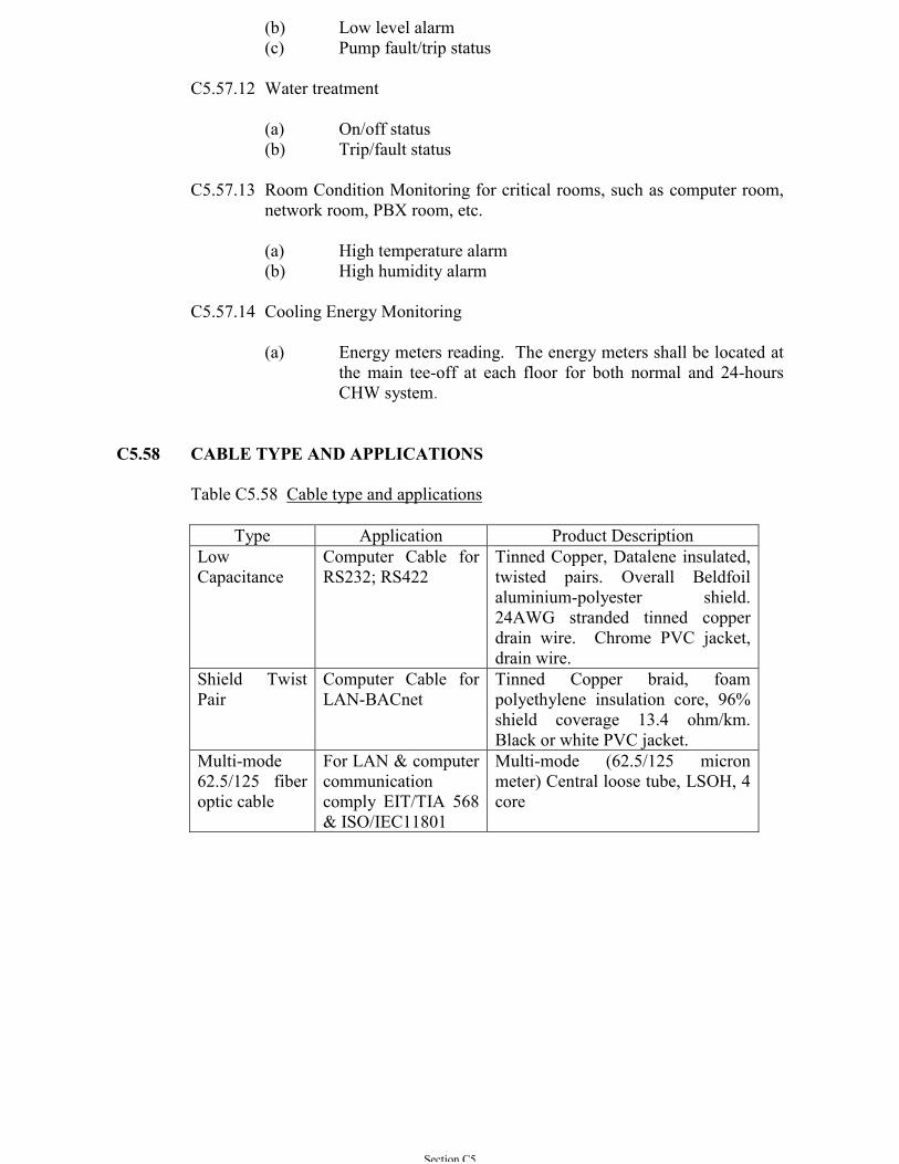
Section C5
(b) Low level alarm(c) Pump fault/trip status
C5.57.12 Water treatment
(a) On/off status(b) Trip/fault status
C5.57.13 Room Condition Monitoring for critical rooms, such as computer room,network room, PBX room, etc.
(a) High temperature alarm(b) High humidity alarm
C5.57.14 Cooling Energy Monitoring
(a) Energy meters reading. The energy meters shall be located atthe main tee-off at each floor for both normal and 24-hoursCHW system.
C5.58 CABLE TYPE AND APPLICATIONS
Table C5.58 Cable type and applications
Type Application Product DescriptionLowCapacitance
Computer Cable forRS232; RS422
Tinned Copper, Datalene insulated,twisted pairs. Overall Beldfoilaluminium-polyester shield.24AWG stranded tinned copperdrain wire. Chrome PVC jacket,drain wire.
Shield TwistPair
Computer Cable forLAN-BACnet
Tinned Copper braid, foampolyethylene insulation core, 96%shield coverage 13.4 ohm/km.Black or white PVC jacket.
Multi-mode62.5/125 fiberoptic cable
For LAN & computercommunicationcomply EIT/TIA 568& ISO/IEC11801
Multi-mode (62.5/125 micronmeter) Central loose tube, LSOH, 4core
Section C6
SECTION C6
CENTRAL REFRIGERATION/CHILLER, DIRECT EXPANSIONEVAPORATOR AND HEAT REJECTION PLANT
C6.1 GENERAL
The refrigeration plant for air conditioning purposes shall generally be of themechanical, vapour compression type using environmental friendly refrigerants.
The refrigeration chillers shall be factory assembled and tested complete ‘packaged’units which may have reciprocating, centrifugal or screw type compressors and asspecified in the Particular Specification or as proposed by the Contractor.
The plant shall include any accessories necessary to ensure continuous and reliableautomatic operation and remote monitoring and control.
Each unit shall be capable of running continuously at the lowest step of cooling orheating capacity provided without any adverse effect.
Compressor and motor speeds shall not exceed 50 revolutions per second forreciprocating type and for screw type. For centrifugal type, the motor speed shallnot exceed 50 revolutions per second and the compressor speed shall not exceed200 revolutions per second Energy efficient motor to optimise the systemcoefficient of performance will be required. If higher compressor speed is specifiedor allowed in the Particular Specification, the refrigeration machine shall beproperly treated with factory-built acoustic silencer to limit the sound pressure levelwithout de-rating the machine efficiency and capacity as specified in the ParticularSpecification.
Each compressor shall form a separate independent oil circuit with its own oilseparator, oil filter and positive lubrication oil safety control circuit equipped toensure proper functioning of each compressor and accessories.
All units shall comply, where applicable, with the following codes: ISO 1662;ANSI B9-1 Safety Code; ARI Standard 50/590-98 Testing and Ratings; VDEElectrical and Wiring Regulations for Earthing; IEE Wiring Regulations.
Characteristic curves shall show the energy consumption in kilowatts, pressure dropthrough the evaporator, chilled or hot water flow rates and temperatures, condenserfan speeds, etc., for each unit at 15%, 25%, 50%, 75% and 100% of full capacity.
Sound power characteristic curves shall be in dB measured in accordance with ARIstandard 575 for 15%, 25%, 50%, 75% and 100% of full capacity.
C6.2 ABSORPTION UNITS
Absorption refrigeration units if required will be fully specified in the ParticularSpecification. They are not commonly used for general refrigeration applications in
Section C6
place of conventional reciprocating, centrifugal or screw types in Hong Kong due toits less favourable energy performance.
C6.3 COLD STORAGE REFRIGERATION
Independent refrigeration circuits shall be supplied and installed at the cold storageroom and shall comprise an air-cooled refrigeration system with semi-hermeticreciprocating compressor connected to each room unit cooler. The unit cooler shallbe of the ceiling type, drawn through direct expansion with distributor, heatexchanger for better efficiency, and electric defrost heaters. Requirements for coldstorage facilities will be fully detailed in the Particular Specification for specificapplication.
C6.4 COMPRESSORS, RECIPROCATING TYPE
C6.4.1 Hermetic compressors will be acceptable where either:-
(a) The entire refrigeration system is completed and chargedwith refrigerant at the manufacturer’s works or,
(b) The condensing unit incorporating the hermetic compressorhas a hold charge of refrigerant or inert gas on arrival at site.
C6.4.2 Crankshafts or eccentric shafts of all open or semi-hermetic compressorsshall be balanced and, if having an input power greater than 2.25 kW, runin replaceable bearings.
C6.4.3 Pistons greater than 50 mm diameter shall be fitted with either:-
(a) Compression and/or oil control rings or,
(b) A combination of compression rings and a piston ringspecially shaped to act as an oil scraper.
C6.4.4 All open and semi-hermetic compressors having an input power inexcess of 350 kW shall have:-
(a) Removable cylinder liners
(b) Side or end covers which will enable servicing or repair ofthe unit to be carried out 'in-situ'
C6.4.5 Open type compressors shall have a rotary mechanical seal fitted to thedriving shaft which effectively prevents leakage of refrigerant or oil.Direct coupled type units shall be driven through a flexible couplingunits. Compressors with an input power greater than 25.0 kW shall be ofa type which will enable the shaft seal to be removed without movingcompressor or motor.
C6.4.6 Open and semi-hermetic compressors of 6.0 kW input power and aboveshall have:-
Section C6
(a) A crankshaft driven oil pump used to force feed lubricant viaa strainer to the main and big end bearings and the shaft seal.
(b) An oil pressure relief valve or bleed device provided betweenthe oil pump discharge and the crankcase.
(c) Provision for draining oil from the suction manifold into thecrankcase and for venting refrigerant gas (but not oil) in theopposite direction.
(d) A crankcase heater arranged to operate while the compressoris at rest.
C6.4.7 All types of compressor, with the exception of hermetic units or factorysealed systems, shall have the following fittings provided andconnected:-
(a) Stop valves on refrigerant suction and discharge connections.
(b) Refrigerant pressure gauges, not less than 75 mm diameterand fitted with means of isolation, on suction and discharge.Gauges shall have pressure and saturation temperature scalesfor the refrigerant being used. Alternatively, gauges withpressure scale only may be used in conjunction with apressure/saturation temperature conversion table fixednearby.
(c) Oil pressure gauge, not less than 75 mm diameter, with meansof isolation (compressors with oil pump only).
(d) Crankcase oil level sight glass.
(e) High and low refrigerant pressure safety cutouts withadjustable differential setpoint. Settings of the protection shallbe preset at the manufacturer’s recommended settings by themanufacturer at factory.
(f) Low oil pressure safety cut-out with hand reset (compressorswith oil pump only).
(g) Suction refrigerant strainer.
(h) All instruments shall be mounted in a neat instrument panelmounted on the package unit or on a varnished teak framemounted panel near to the machine being served and to adesign acceptable to the Architect.
Alternatively, pressure measurements read from the display panel of thechiller is acceptable.
Section C6
C6.4.8 All compressors having a refrigeration duty in excess of 35 kW shallhave capacity control by means of cylinder unloading. Compressorsshall be arranged so that they start unloaded.
The hot gas by-pass or injection system of capacity control will not beaccepted.
C6.5 COMPRESSORS, CENTRIFUGAL TYPE
C6.5.1 Open type centrifugal compressors shall have a rotary seal fitted to thedriving shaft which effectively prevents leakage of refrigerant or oil.Open compressors shall be driven through a flexible coupling of a typewhich enables the shaft seal to be removed without moving thecompressor or motor.
C6.5.2 The lubrication system shall be arranged with an interlock to ensureadequate oil pressure at all bearings before the compressor starts andduring the 'coast down' period. A replaceable or cleanable filter shall bepositioned in the oil delivery pipe. Where an oil cooler is used, it shallbe thermostatically controlled. A hand reset pressure or flow switchshall stop the compressor on a lubrication system failure. The oil sumpshall have a thermostatically controlled electric heater which operateswhile the compressor is at rest.
C6.5.3 The compressor shall have automatic capacity regulation which willcontrol at any point from 30% to 100% of full duty without inducing asurge condition. The compressor shall always start in the unloadedcondition.
The hot gas by-pass or injection system of capacity control will not beaccepted.
C6.5.4 The motor of a semi-hermetic compressor which is refrigerant gas cooledshall have in-built protection against inadequate cooling.
C6.5.5 The following fittings shall be provided and connected:-
(a) Refrigerant pressure gauges as Sub-section C6.4.7(b).
(b) Oil pressure gauge as Sub-section C6.4.7(c).
(c) Oil sump or reserve level sight glass.
(d) Pressure safety cut-outs as Sub-section C6.4.7(e).
(e) Low oil pressure or flow switch with hand reset.
(f) High oil temperature cut-out with hand reset.
(g) Instrument mounting as Sub-section C6.4.7(h).
(h) Stop valve on refrigerant discharge and suction.
Section C6
Alternatively, pressure measurements read from the display panel of thechiller is acceptable.
C6.6 COMPRESSORS, SCREW TYPE
C6.6.1 Screw compressors shall have quiet operation with oil injectionlubrication system. Open compressors shall have a rotary seal fitted tothe driving shaft which effectively prevents leakage of refrigerant or oil.Open compressors shall be driven through a flexible coupling of a typewhich enables the shaft seal to be removed without moving compressoror motor.
C6.6.2 A device shall be fitted to prevent the pressure differential across thecompressor causing backward rotation at a normal or emergency stop.
C6.6.3 The lubrication system shall be arranged with an interlock to ensureadequate oil pressure at all bearings before the compressor starts. A handreset pressure or flow switch for stopping the compressor shall be fittedat a appropriate location from the oil pump delivery pipe to the oil sump.A replaceable or thermostatically controlled oil cooler shall be used toremove the heat gained by the oil in the rotor chamber or the chillermanufacturer shall select and confirm that the lubrication oil used can beoperated at a temperature higher than the rotor chamber. The oil sumpshall have a thermostatically controlled electric heater which operateswhile the compressor is at rest.
C6.6.4 The compressor shall have automatic capacity control equipment whichwill control at any point between 10% and 100% of full duty via control ofthe compressor speed by variable speed drive or slide valve. Forcompressor with stepped capacity loader control, each chiller shall havecapacity control steps as specified in Particular Specification and theminimum step capacity shall be maximum 20% of full load. Thecompressor shall be fitted with a device which ensures that it cannot startunless in the fully unloaded condition.
Except where indicated in the Particular Specification, the hot gas by-pass or injection system of capacity control will not be accepted.
The motor of a semi-hermetic compressor which is refrigerant gas cooledshall have in-built protection against inadequate cooling.
The following fittings shall be provided and connected:-
(a) Stop valves on refrigerant discharge and suction.
(b) Refrigerant pressure gauges as Sub-section C6.4.7(b).
(c) Oil pressure gauge as Sub-section C6.4.7(c).
(d) Oil sum or reservoir level sight glass.
Section C6
(e) Pressure safety cut-outs as Sub-section C6.4.7(e).
(f) Low oil pressure or flow switch with hand reset.
(g) High oil temperature cut-out with hand reset.
(h) Instrument mounting as Sub-section C6.4.7(h).
Alternatively, pressure measurements read form the display of the chilleris acceptable.
C6.6.5 Screw compressor for ammonia chiller
(a) The casing of screw compressor for ammonia chiller shall bedesigned to maximize strength to weight ratio and properlygasketed to prevent leakage. The compressor shall bedesigned for a maximum allowable working pressure higherthan 2600 kPa. Suction filter and oil filter shall be provided.A check valve shall be provided at the suction side to preventthe counter rotation due to pressure equalization.
(b) The screw compressor unit shall be complete with a variablevolume ratio pressure equalization device to maintain thehighest efficiency under all working conditions on both theevaporator load side and the condenser cooling medium side.Control shall take place in two stages high and low volumeratio. The device shall consist of one control and oneregulating piston. The unit is connected to the compressorhigh, intermediate and low pressure systems. These pressuresact on different surfaces of the control piston and accordingto the internal ratio between the pressures the piston willopen or close the flow of high pressure oil to the regulatingpiston. When the high pressure oil acts on this piston, itpartly closes the compressor discharge port, which producesa high volume ratio. When the high pressure oil is drained,the reverse actions apply and the regulating piston opens partof the discharge port, giving a low volume ratio.
C6.7 CONDENSERS, SHELL AND TUBE (FRESH COOLING WATERAPPLICATION)
C6.7.1 Condensers shall be of the manually cleanable type capable of being re-tubed ‘in-situ’.
C6.7.2 For fresh water condenser cooling applications, the condenser shall be ofsteel and the water boxes/end covers shall be of steel or cast iron.
C6.7.3 The tubes shall be of copper, aluminium brass, cupro-nickel, grade 316stainless steel or as otherwise indicated in the Particular Specification.The tube plates may be of the same alloys or alternatively made in mildsteel with a ‘Cladding’ of stainless steel.
Section C6
C6.7.4 Internal baffles and other fittings in either water or refrigerant circuitsshall be made of material such that they will not corrode or set upcorrosion or permit electro-chemical action with the liquids and/or othermaterials used in the condensers.
C6.7.5 End water boxes shall be designed to provide adequate space for watermovement such that there is no erosion of the tube ends. In general, thisrequires the water box end to be domed rather than flat. The water boxesshall be epoxy resin coated internally to prevent corrosion.
C6.7.6 End box covers shall be removable, and allow easy access for cleaning thetubes. Means shall be provided for venting and draining of the water sideof the unit.
C6.7.7 The design fouling factor on the water side of the tubes shall be 0.000044m2 oC/W for cooling tower fresh water.
C6.8 CONDENSERS, SHELL & TUBE (SEA OR BRACKISH COOLINGWATER APPLICATION)
C6.8.1 Condensers shall be of the manually cleanable type capable of being re-tubed ‘in-situ’.
C6.8.2 For sea water or brackish water condenser cooling applications, thecondenser shell shall be of steel and the water box/end covers shall be ofsteel or cast iron.
C6.8.3 The tubes shall be titanium and the tube plate titanium clad steel.
C6.8.4 Ditto as Sub-section C6.7.4.
C6.8.5 Ditto as Sub-section C6.7.5 In addition the water boxes shall be providedinternally with a sacrificial zinc anode at both ends.
C6.8.6 Ditto as Sub-section C6.7.6.
C6.8.7 Ditto as Sub-section C6.7.7 except that the design fouling factor shall be0.000132m2 oC/W
C6.9 CONDENSERS, SHELL AND TUBE-GENERAL REQUIREMENT
C6.9.1 The positioning of the condenser shall be such that removal ormaintenance of the tubes is not obstructed by walls, pipework, valves etc.
C6.9.2 Means shall be provided for the controlled venting of non-condensablesfrom the refrigerant side of the condenser. For Refrigerant134a this maybe manually controlled.
C6.9.3 Automatic control of the condensing pressure shall be incorporated.
Section C6
C6.9.4 The refrigerant and water systems shall be pressure tested at themanufacturer’s work in accordance with Section A9 and ISO 1662.
C6.10 CONDENSERS, AIR COOLED
C6.10.1 Air cooled condensers shall have copper tubes with:
- Aluminium fin coated with corrosion protection coating, or- Electro-tinned copper fins, or- As otherwise indicated in the Particular Specification.
Corrosion protection coating of the condenser fins shall be applied infactory by the chiller manufacturer. Fins with minor damage shall becombed straight. Units with extensive damage to fins will not beaccepted. Provision shall be made for the purging of non-condensablesfrom the condenser.
C6.10.2 Air cooled condensers mounted outside buildings shall have weather-proof fan motors. The units shall discharge air vertically upwards.
C6.10.3 Automatic control of the condensing pressure shall be incorporated.Where modulation of air flow is by outlet dampers only, the fan motorshall be selected for this application and arranged so that it is de-energised on complete closure of the dampers.
C6.10.4 Fans shall comply with limitations on permitted noise levels whereindicated in the Particular Specification. Fans shall have sufficient staticpressure to cater for the additional acoustic treatment such as silencer, ifany, in order to meet the noise requirements set out in Section C8 and theParticular Specification.
C6.10.5 The complete condenser coil shall be pressure tested at themanufacturer’s work in accordance with Section A9.
C6.11 CONDENSERS, EVAPORATIVE
These are not normally used in Hong Kong. Should such equipment be required, itwill be fully detailed with in the Particular Specification.
C6.12 COOLING TOWER
C6.12.1 Cooling towers shall be of the type with induced or forced draught fansas indicated. The entering and leaving water temperatures and the waterflow rate shall be suitable for peak heat rejection rate at the maximumambient wet bulb temperature indicated in the Particular Specification.
C6.12.2 Casings shall be of glass reinforced plastics (GRP), or as indicated. Thecasing shall have a treatment to minimise corrosion or decay and suitablefor the casing material used. The casing and structure shall withstandextreme typhoon gale force winds from any direction.
Section C6
C6.12.3 The water distribution system shall be easily cleanable to minimisecollection of deposits and growth of algae which might encourage thegrowth of “legionella preumophila” bacteria, and also be protected by astrainer. Open distribution pans or troughs shall be fitted with coarsemesh grids to exclude debris.
C6.12.4 Fill shall be of the film-type, vacu-formed PVC, with louvres and drifteliminators formed as part of the fill sheets. Fill sheets shall beindividually suspended from stainless steel structural tubing, or by othersuitable methods, supported by the tower columns and intermediatestainless steel panels, and shall be elevated above the floor of the coldwater basin to facilitate cleaning. Air inlet faces of the tower shall be freeof water splash-out, and guaranteed drift losses shall not exceed 0.005%of the design water flow. All packing shall be resistant to corrosive attackby algae, fungal growth, the type of condenser water used or thechemicals used to treat the condenser water.
C6.12.5 Where the tower is to circulate sea water, treated wastewater effluents orbrackish well water, all components must be capable of withstanding thecorrosive effects of these liquids. All metal parts shall be of zinc freebronze or suitable grades of stainless steel coated after installation byheavy bituminous or suitable epoxy resin coatings. Measures shall alsobe taken against insect and fungus attack. The packing material shall notdistort in any manner which would obstruct the air or water flow.
C6.12.6 The cooling tower ‘basin’ shall be provided in reinforced concrete to aspecified standard by the Building Contractor. Alternatively, if specifiedto be provided in the Specialist Services Contract, it shall be of suitablestainless steel, GRP or as otherwise indicated. Sheet mild steel basins ifspecified (for fresh water applications only) shall be hot dippedgalvanised after manufacture and have two coats of an approved anti-corrosion paint applied.
C6.12.7 The GRP hot water distribution basin shall be equipped with meteringorifice-type nozzles to deliver incoming water by gravity to the fill.Nozzles shall be easily removable and replaceable.
C6.12.8 The GRP cold water basin shall be sealed watertight, and shall include afloat-operated mechanical make-up valve, a 100 mm diameter overflowconnection and a depressed GRP sump complete with a debris screenmade of stainless steel or other suitable corrosion resistant material. Theassembly shall be hot-dip galvanized after fabrication and painted.
C6.12.9 The capacity of the basin shall be sufficient to prevent overflow when thetower is at rest. There shall be adequate and easy access for cleaning outthe basin.
C6.12.10 Fans shall be of the axial type mounted to provide a vertical upwards airdischarge. In circumstances where centrifugal units are required, thesewill be fully specified in the Particular Specification.
Section C6
Particular attention must be given to the limitations on permitted noiselevels, where indicated. However, where not indicated, noise levels mustbe restricted and must be stated with the plant offered. Plant likely togenerate unacceptable noise will not be accepted.
Fan casings and impellers shall either be made of corrosion resistantmaterial or proofed against corrosion after manufacture. Fan motorsshall be totally enclosed and weatherproofed. Fan motors on induceddraught units shall have suitable protective treatment as they will bemounted in the moist air stream.
Belt or gear drives shall be readily accessible but fully protected againstthe weather and personnel. Anti-vibration ‘cut-out’ devices shall beprovided to protect the fans drive etc. Warning of a ‘cut-out’ shall bewired back to the plantroom in order to draw attention to any suchproblem.
C6.12.11 A bleed pipe with stop valve and flow regulating device shall beprovided on each cooling tower.
C6.12.12 Where indicated, chemical treatment equipment for maintenance ofcooling water quality shall be provided generally in accordance withSection A7.
C6.13 EVAPORATORS, SHELL & TUBE WATER CHILLING
C6.13.1 Evaporators shall be of the shell and tube type, capable of being re-tubed‘in-situ’. Where an evaporator which cannot be re-tubed ‘in-situ’ isrequired, it shall have the refrigerant and water connections flanged andbe mounted on the packaged unit in a manner which permits easyremoval. The design fouling factor on the closed circulation water sideof the tubes shall be 0.000018 m2 oC/W.
C6.13.2 The evaporator shell and tube plates shall be of steel and the waterboxes/end covers shall be of steel or cast iron. The tubes shall be ofcopper, aluminium brass, cupro-nickel, grade 316 stainless steel or asotherwise indicated in the Particular Specification. The water box/endcovers shall be removable and the plant components arranged such thatthe space for tube removal is not obstructed.
C6.13.3 The flow of refrigerant to a multiple circuit dry expansion evaporatorshall be controlled by an externally equalised thermostatic or electronicexpansion valve which shall not ‘hunt’ at any step of compressorunloading. The design of the refrigerant passages in direct expansiontype evaporators shall be such that any oil present is always carried backto the compressor at the lowest stage of capacity reduction.
C6.13.4 Where a fixed orifice expansion system is used with a semi-floodedevaporator, a durable nameplate shall be permanently fixed adjacent tothe sight glass, in the refrigerant liquid pipe feeding the orifice, withwording as follows:-
Section C6
‘Bubbles do not always indicate refrigerant undercharge. The Contractorshall refer to special charging instructions’ by the Manufacturer forrefrigerant changing.
C6.13.5 Provision shall be made on flooded and semi-flooded evaporators forreturning oil from the evaporator to the compressor. If the system usesand passes oil-rich refrigerant into the compressor suction pipe it shallnot damage the compressor or cause foaming of the oil in the sump.
C6.13.6 The refrigerant and water systems shall be pressure tested at themanufacturer’s works in accordance with Section A9 and ISO1662.
C6.14 EVAPORATORS, AIR COOLING
C6.14.1 Air coolers using direct expansion of primary refrigerant shall beprovided with refrigerant distributors. Connections to the tubes shall bedesigned to ensure equal flow of refrigerant to each tube.
C6.14.2 The flow of refrigerant to a multiple circuit with dry expansionevaporator shall be controlled by an externally equalised thermostatic orelectronic expansion valve which shall not ‘hunt’ at any step ofcompressor unloading.
C6.14.3 The design of the refrigerant passages in direct expansion typeevaporation shall ensure that the return (or suction) connections arearranged such that any oil present is always carried back to thecompressor even at the lowest stage of capacity reduction.
C6.15 PLATE TYPE HEAT EXCHANGER
C6.15.1 Heat exchangers shall consist of most energy efficient metal platespressed into a “Herring Bone” pattern and securely clamped betweennitrile rubber gaskets by the pressure end plates of the mild steelframework. Plates shall be stainless steel for fresh water or titanium forsea/well water. The plates shall be suspended from the top bar of theframework and located on the bottom guide bar. No part of the mild steelframework shall be in contact with the heat transfer fluids.
C6.15.2 Heat transfer plates shall be clamped by lateral bolts between a stationaryframe plate and a movable pressure plate such that opening of the plateheat exchangers can be done without removing any connecting pipes.
C6.15.3 Heat exchanger shall be designed to give a high heat transfer efficiency toachieve close approach temperatures as low as 1 oC.
C6.15.4 Heat exchanger frame shall be of mild steel and shall be suitable forbolting to a horizontal deck. The frames shall be arranged such thatwhen the tie bars are loosened, full access to all plate surfaces isprovided for cleaning and maintenance. The entire framework and allparts of the units shall be factory treated to prevent corrosion such thatthe heat exchanger shall be capable of corrosive environment. All
Section C6
holding down bolts shall be of high tensile carbon steel with plastic tubeprotection. Each shall be equipped with bearing boxes and a lockingwasher enables the bolts to be opened from the fixed cover. No weldedparts are allowed.
C6.15.5 Inlet and outlet ports shall be rubber lined or metal lined constructed on thefixed frame plate only.
C6.15.6 The heat transfer plates for fresh water application shall be of stainlesssteel and in a corrugated pattern with thickness of 0.6 mm minimum, andpressing depth of about 3.20 mm with pressure rating a minimum of 1000kPa or other rating to suit system design as specified. Maximum plate packlength shall not exceed 45% of the total framework length. Double gasketsshall be provided around the bypass port on each plate, with a drain holebetween the gaskets to facilitate leak detection.
C6.15.7 Distribution area shall be ‘chocolate pattern’ and the flow pattern shall be‘counterflow’. Gasket shall be on every plate to eliminate interleakagebetween media.
C6.15.8 The heat exchanger units shall be pressure tested in the factory prior todelivery. The plate heat exchanger shall have a working pressure range of1000 to 2500 kPa and shall be tested with a minimum pressure of 1500to 3500 kPa for 24 hours suitable to the system design application asspecified. Full certification of test results and guarantee for 5-yearperformance free from leakage by the manufacturer shall be provided.
C6.15.9 The heat exchanger for chilled or hot water application shall be properlyinsulated with optimum efficiency and robust insulation against heat loss.The insulation panels shall be of the double skin aluminium/stainlesssteel cladded type with handles suitable for easy removable for platesaccess for inspection and maintenance. An insulated stainless steel driptray shall also be equipped for chilled water application.
C6.16 LIQUID RECEIVERS
C6.16.1 Except in the case of window units, factory package units and hermeticsealed units equipped with oversized condenser to hold the systemrefrigerant during pump down operation, all other refrigerationequipment/system with capacity over 350 kW are to be equipped with arefrigerant liquid receiver of sufficient capacity to take the whole chargeof the system. The liquid receiver shall consist of a steel shell withdished endplates. It shall be complete with inlet and outlet valves, reliefvalves, sight glasses and all necessary fittings and accessories.
C6.16.2 Liquid refrigerant receivers shall be separate units. Combinationcondenser/receivers are not acceptable. One receiver shall be providedfor each condensing unit.
C6.16.3 The liquid receiver shall have a capacity of 1.2 times the system chargeand wherever possible, shall be provided as part of the packaged chiller
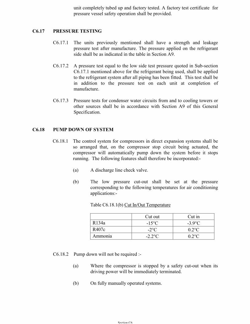
Section C6
unit completely tubed up and factory tested. A factory test certificate forpressure vessel safety operation shall be provided.
C6.17 PRESSURE TESTING
C6.17.1 The units previously mentioned shall have a strength and leakagepressure test after manufacture. The pressure applied on the refrigerantside shall be as indicated in the table in Section A9.
C6.17.2 A pressure test equal to the low side test pressure quoted in Sub-sectionC6.17.1 mentioned above for the refrigerant being used, shall be appliedto the refrigerant system after all piping has been fitted. This test shall bein addition to the pressure test on each unit at completion ofmanufacture.
C6.17.3 Pressure tests for condenser water circuits from and to cooling towers orother sources shall be in accordance with Section A9 of this GeneralSpecification.
C6.18 PUMP DOWN OF SYSTEM
C6.18.1 The control system for compressors in direct expansion systems shall beso arranged that, on the compressor stop circuit being actuated, thecompressor will automatically pump down the system before it stopsrunning. The following features shall therefore be incorporated:-
(a) A discharge line check valve.
(b) The low pressure cut-out shall be set at the pressurecorresponding to the following temperatures for air conditioningapplications:-
Table C6.18.1(b) Cut In/Out Temperature
Cut out Cut inR134a -15°C -3.9°CR407c -2°C 0.2°CAmmonia -2.2°C 0.2°C
C6.18.2 Pump down will not be required :-
(a) Where the compressor is stopped by a safety cut-out when itsdriving power will be immediately terminated.
(b) On fully manually operated systems.
Section C6
C6.19 REFRIGERANT PIPEWORK
C6.19.1 Pipework for refrigerant systems shall be of copper or steel, which shallbe internally degreased and cleaned. Copper pipe shall be ofrefrigeration quality (i.e. material to BS EN 1057 ).
C6.19.2 For all chloro-fluoro-methane or ethane compounds :-
(a) All pipes up to 18 mm OD shall be of fully annealed copper.
(b) All pipes from 22 mm to 108 mm OD shall be of hard drawncopper.
(c) All pipes over 108 mm OD shall be of black extra heavyseamless steel pipe to ISO 2604 grade 360.
(d) On fully packaged chiller units, pipework other than copper,i.e. steel fitted and tested in the factory as standardproduction for the units, will be acceptable subject tonotification and written approval by the Architect.
C6.19.3 For ammonia system:-
Steel - whatever size is technically necessary or as specified in theParticular Specification.
All materials used in the refrigerant circuit shall be suitable for use in thepresence of ammonia refrigerant or lubricating oil, or a combination ofboth, and comply with ANSI Code B31.5, 1974 or ASME Boiler andPressure Vessel Code, 1984 Section VIII, and meet with system pressure-temperature requirement so that they will not corrode or cause corrosionwhen in contact with the fluids conveyed.
C6.19.4 Size of Refrigerant Piping:-
Refrigerant piping shall be sized to avoid excessive pressure drop of thefluids or gases they carry. The recommendations of the CharteredInstitution of Building Services Engineers (UK) and/or the AmericanSociety of Heating, Refrigeration and Air-conditioning Engineers/orother reputable/factory standards approved by the Architect on the sizingof refrigerant piping shall be complied with.
C6.20 REFRIGERATION PLANT ACCESSORIES & CONTROLS
C6.20.1 Every refrigeration system shall be protected by a pressure relief deviceunless it is so constructed that pressure due to fire conditions would besafely relieved. The equipment provided shall comply with ISO 1662and the outlet piped to discharge outside the building.
C6.20.2 Systems using a thermostatic expansion valve shall have the followingitems preceding it in the refrigerant liquid pipe :-
Section C6
- A solenoid valve- A sight glass- A refrigerant drier (replaceable)- A refrigerant strainer- A capped refrigerant charging valve
C6.20.3 An evaporator pressure regulating valve where fitted shall be protectedby a strainer, and an evaporator pressure gauge shall be provided, up-stream of the valve, fitted with means of isolation.
C6.20.4 Units having a direct expansion evaporator at a higher level than thecompressor shall operate on a pump down cycle. On water chillinginstallations, the chilled water pump shall be kept running during thisprocess.
C6.20.5 Refrigerant stop valves which incorporate a spindle gland shall be of theback seat type. The spindle gland shall be serviceable with the valve ‘in-situ’.
C6.20.6 A flow switch shall be provided in the chilled water pipeline to eachshell and tube evaporator to prevent the compressor starting orcontinuing to run if the water flow is below the minimum stipulated bythe evaporator manufacturer.
C6.20.7 A low temperature thermostat with hand reset shall be provided for eachshell and tube evaporator to stop the compressor(s) if the chilled waterflow temperature falls below +3 oC.
C6.20.8 Full flow driers with strainers shall be supplied for all refrigerant liquidlines and shall be complete with isolating valves and bypassarrangements. Driers shall be of the renewable cartridge type.
A suitable colour moisture indicator shall be provided, either built-in tothe drier, or as a separate component installed adjacent to the drier toshow through a suitable glass eye whether the moisture content of therefrigerant is within permissible limits.
C6.20.9 Strainers shall be provided before all expansion valves, float valves,solenoid valves, etc. Except where the expansion valve is fitted justdownstream of a solenoid valve, only one strainer needs to be fitted.
C6.20.10 Full flow strainers of the cleanable and renewable type shall be fitted atthe suction of all compressors.
All strainers and driers shall be easily and readily accessible for cleaningor replacement of cartridges.
C6.20.11 Full flow oil filters shall be incorporated in all force-feed lubricatingsystem. Magnetic separators shall also be provided.
C6.20.12 Where oil separation equipment is to be provided, it shall be completewith traps, strainers, floats, receivers and gauges.
Section C6
The oil separator shall be a fabricated steel shell with dished steelendplates and ample and accessible cleaning handholes. The oil returncontrol floats shall not be fitted inside the shell. No pipes shall be fittedinside the shell. No pipes shall be connected through the lids of cleaningor access holes. Adequate provision shall be made for purifying andflushing the system.
C6.20.13 Energy meters shall be provided for chilled (or hot) water system forenergy audit purposes. The specification/requirement of the energymeters shall be as described in Section C10.
C6.21 ROOF MOUNTED PACKAGED WATER CHILLER PLANTS
C6.21.1 The Units shall include the number and type of compressors indicated inthe Particular Specification, with air cooled condenser coils, condenserfans and motors, shell and tube direct expansion evaporator water chiller.
C6.21.2 Expansion valves controls and safety devices shall all be housed in asubstantial weatherproofed casing.
C6.21.3 Where specified in the Particular Specification, units shall have full noisesuppression treatment with outlet silencers generally as covered inSections B8 and C8.
C6.21.4 Unitary package chiller units shall conform to and shall have rated andtested capacity to the requirements of ARI Standard 210 or other equalInternationally Recognised Standard accepted by the Architect.
C6.22 HEAT RECOVERY CHILLER
C6.22.1 Heat recovery chiller unit shall be complete with a heat recoverycondenser and condensing unit, three-way valve, receivers etc. The exactconfiguration of these devices shall follow the details recommended bythe chiller manufacturer. The heat which is normally rejected to the air-cooled or water-cooled condenser shall be reclaimed and made availablethrough the heat recovery condenser and other provisions as specified,for a variety of uses aiming to optimize the building energy performance.
C6.22.2 All the waste heat shall be reclaimed by adding a heat recoverycondenser, refrigerant control valve, liquid line receiver and controls tothe standard air-cooled or water-cooled chiller, making it as a heatrecovery chiller. The heat recovery chiller shall have only one refrigerantcontrol valve which makes its operation reliable, simple to control andeasy to maintain.
C6.22.3 During operation in the cooling mode, the hot refrigerant gas shall becondensed only in the normal air-cooled or water-cooled condenser, thesystem cooling load heat and the heat of compression shall be rejected tothe atmosphere via this condenser. The system shall sub-cool the liquidrefrigerant which shall increase the capacity of the machine by up to 12percent without increasing power consumption. The condenser fans shall
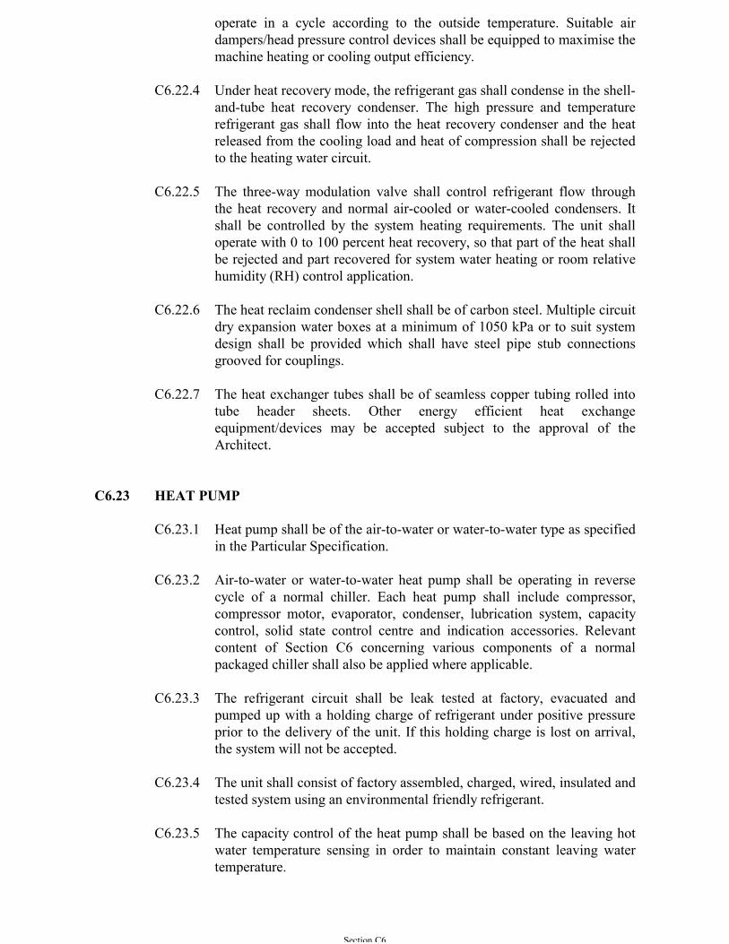
Section C6
operate in a cycle according to the outside temperature. Suitable airdampers/head pressure control devices shall be equipped to maximise themachine heating or cooling output efficiency.
C6.22.4 Under heat recovery mode, the refrigerant gas shall condense in the shell-and-tube heat recovery condenser. The high pressure and temperaturerefrigerant gas shall flow into the heat recovery condenser and the heatreleased from the cooling load and heat of compression shall be rejectedto the heating water circuit.
C6.22.5 The three-way modulation valve shall control refrigerant flow throughthe heat recovery and normal air-cooled or water-cooled condensers. Itshall be controlled by the system heating requirements. The unit shalloperate with 0 to 100 percent heat recovery, so that part of the heat shallbe rejected and part recovered for system water heating or room relativehumidity (RH) control application.
C6.22.6 The heat reclaim condenser shell shall be of carbon steel. Multiple circuitdry expansion water boxes at a minimum of 1050 kPa or to suit systemdesign shall be provided which shall have steel pipe stub connectionsgrooved for couplings.
C6.22.7 The heat exchanger tubes shall be of seamless copper tubing rolled intotube header sheets. Other energy efficient heat exchangeequipment/devices may be accepted subject to the approval of theArchitect.
C6.23 HEAT PUMP
C6.23.1 Heat pump shall be of the air-to-water or water-to-water type as specifiedin the Particular Specification.
C6.23.2 Air-to-water or water-to-water heat pump shall be operating in reversecycle of a normal chiller. Each heat pump shall include compressor,compressor motor, evaporator, condenser, lubrication system, capacitycontrol, solid state control centre and indication accessories. Relevantcontent of Section C6 concerning various components of a normalpackaged chiller shall also be applied where applicable.
C6.23.3 The refrigerant circuit shall be leak tested at factory, evacuated andpumped up with a holding charge of refrigerant under positive pressureprior to the delivery of the unit. If this holding charge is lost on arrival,the system will not be accepted.
C6.23.4 The unit shall consist of factory assembled, charged, wired, insulated andtested system using an environmental friendly refrigerant.
C6.23.5 The capacity control of the heat pump shall be based on the leaving hotwater temperature sensing in order to maintain constant leaving watertemperature.
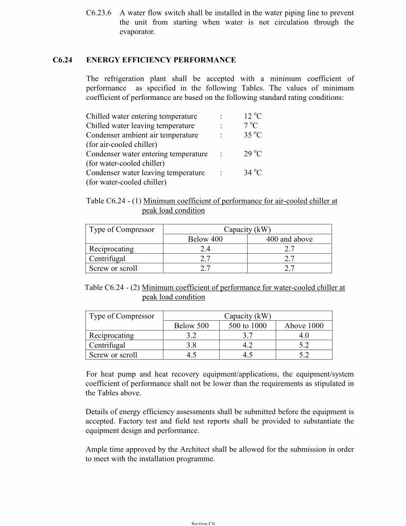
Section C6
C6.23.6 A water flow switch shall be installed in the water piping line to preventthe unit from starting when water is not circulation through theevaporator.
C6.24 ENERGY EFFICIENCY PERFORMANCE
The refrigeration plant shall be accepted with a minimum coefficient ofperformance as specified in the following Tables. The values of minimumcoefficient of performance are based on the following standard rating conditions:
Chilled water entering temperature : 12 oCChilled water leaving temperature : 7 oCCondenser ambient air temperature : 35 oC(for air-cooled chiller)Condenser water entering temperature : 29 oC(for water-cooled chiller)Condenser water leaving temperature : 34 oC(for water-cooled chiller)
Table C6.24 - (1) Minimum coefficient of performance for air-cooled chiller atpeak load condition
Capacity (kW)Type of CompressorBelow 400 400 and above
Reciprocating 2.4 2.7Centrifugal 2.7 2.7Screw or scroll 2.7 2.7
Table C6.24 - (2) Minimum coefficient of performance for water-cooled chiller at peak load condition
Capacity (kW)Type of CompressorBelow 500 500 to 1000 Above 1000
Reciprocating 3.2 3.7 4.0Centrifugal 3.8 4.2 5.2Screw or scroll 4.5 4.5 5.2
For heat pump and heat recovery equipment/applications, the equipment/systemcoefficient of performance shall not be lower than the requirements as stipulated inthe Tables above.
Details of energy efficiency assessments shall be submitted before the equipment isaccepted. Factory test and field test reports shall be provided to substantiate theequipment design and performance.
Ample time approved by the Architect shall be allowed for the submission in orderto meet with the installation programme.
Section C7
SECTION C7
ELECTRIC MOTORS AND ELECTRICAL EQUIPMENT
C7.1 LOW VOLTAGE - GENERAL
The mains for the low voltage electrical motors and equipment shall be suitable fora supply as specified in Sub-section A3.1.11.
Unless otherwise indicated, all electrical equipment shall be tropicalised andsuitable for use in service conditions as specified in Sub-section A3.1.10.Equipment shall be protected against atmospheric corrosion, including that causedby salt-laden air. Materials used shall not be susceptible to mould growth or attackby vermin.
Cables for power circuits shall not be less than 2.5 mm2 copper conductors andcables for control circuit shall not be less than 1.5 mm2 copper conductors.
The content related with Control and Metering shall be closely read in conjunctionwith the relevant parts of Sections C4, C5 and C10.
C7.2 LOW VOLTAGE - WIRING FOR REFRIGERATED SITUATIONS
All electric wiring to be installed into refrigerated situations where the temperatureis to be maintained at or below 0ºC shall be either MICS or elastomeric cables thatare applicable for the designed operating environment.
C7.3 LOW VOLTAGE - ELECTRIC MOTORS
C7.3.1 General
All electric motors shall be of the high efficiency squirrel-cage inductiontype and comply with the relevant parts of IEC 60034.
The motors shall be insulated IEC 60085 with Class F as the minimuminsulation.
Motor enclosures shall be in accordance with BS EN 60034-5 and the'degree of protection' shall be appropriate to the location in which themotors are operating and the environment indicated. Unless otherwisespecified, motors shall be protected with enclosures to at least IP 44 forindoor and IP 55 for outdoor application.
Motors of 2.2 kW output or above shall be suitable for operation fromthree-phase supply.
The synchronous speed of the motor shall not exceed 25 rev/s unlessotherwise approved.
C7.3.2 Insulation Test
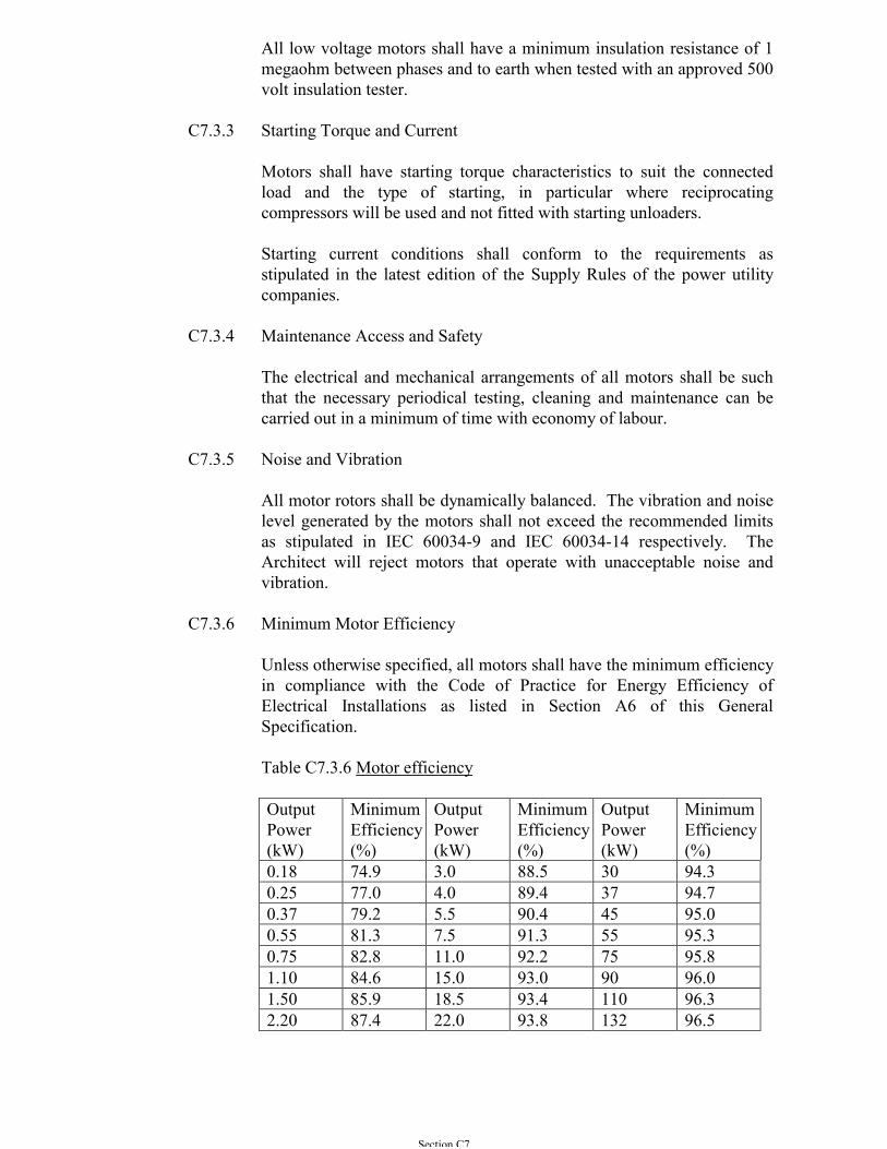
Section C7
All low voltage motors shall have a minimum insulation resistance of 1megaohm between phases and to earth when tested with an approved 500volt insulation tester.
C7.3.3 Starting Torque and Current
Motors shall have starting torque characteristics to suit the connectedload and the type of starting, in particular where reciprocatingcompressors will be used and not fitted with starting unloaders.
Starting current conditions shall conform to the requirements asstipulated in the latest edition of the Supply Rules of the power utilitycompanies.
C7.3.4 Maintenance Access and Safety
The electrical and mechanical arrangements of all motors shall be suchthat the necessary periodical testing, cleaning and maintenance can becarried out in a minimum of time with economy of labour.
C7.3.5 Noise and Vibration
All motor rotors shall be dynamically balanced. The vibration and noiselevel generated by the motors shall not exceed the recommended limitsas stipulated in IEC 60034-9 and IEC 60034-14 respectively. TheArchitect will reject motors that operate with unacceptable noise andvibration.
C7.3.6 Minimum Motor Efficiency
Unless otherwise specified, all motors shall have the minimum efficiencyin compliance with the Code of Practice for Energy Efficiency ofElectrical Installations as listed in Section A6 of this GeneralSpecification.
Table C7.3.6 Motor efficiency
OutputPower(kW)
MinimumEfficiency(%)
OutputPower(kW)
MinimumEfficiency(%)
OutputPower(kW)
MinimumEfficiency(%)
0.18 74.9 3.0 88.5 30 94.30.25 77.0 4.0 89.4 37 94.70.37 79.2 5.5 90.4 45 95.00.55 81.3 7.5 91.3 55 95.30.75 82.8 11.0 92.2 75 95.81.10 84.6 15.0 93.0 90 96.01.50 85.9 18.5 93.4 110 96.32.20 87.4 22.0 93.8 132 96.5

Section C7
C7.3.7 Continuous Rating
The motors shall be continuously rated to BS EN 60034-1. They shallbe adequately rated to meet the service demands of driven unitsconnected thereto under normal conditions without overload. Thecontinuous rating of the motors shall cover the full specified range ofduty plus a further 5% margin for compressors, 15% margin for fans and10% for pumps.
C7.3.8 Tachometers
In all cases of direct drive (except hermetic), an application point shall beprovided for speed checking by a tachometer.
C7.3.9 Terminals
One large terminal box of approved design shall be provided, mountedon the stator casing only. Each end of each stator phase must be broughtout to a terminal in the box. For motors rated 10 kW and above,adequate clearance between termination shall be allowed for the use ofcable sockets.
C7.3.10 Anti-condensation Heater
Anti-condensation heater shall be provided in sea water pump motorslocated inside water-front pump chambers, or motors above 30 kW.
C7.3.11 Belt Drives and Pulleys
Belt drives shall comply with BS 3790 and be capable of transmitting atleast the rated power output of the driving motor with one belt removed.A minimum of two belts per drive shall be used and all multi-belt drivesshall use matched sets.
Slide rails shall be provided for all motors driving through belts.Purpose-made adjusting devices shall be provided to enable belt tensionto be altered and motors to be secured.
Belt driven fans shall be fitted with pulleys suitable for the belt driveused. Pulleys may use split taper bushings for drives up to 30 kW.Alternatively, and in any case for output above 30 kW, pulleys shall besecured to the fan and motor shafts by keys fitted into machinedkeyways. Keys shall be easily accessible so that they can be withdrawnor tightened. Where gib head keys are used they shall not protrudebeyond the end of the shaft. For keys without gib heads, they shall bedrilled and tapped to accept an extractor bolt.
C7.3.12 Protective Guards
Protective fixed guards shall be provided at all open intakes and exhaustsfrom fans, for all forms of open power transmission systems includingbelt drives and drive couplings, and to dangerous parts of machinery to
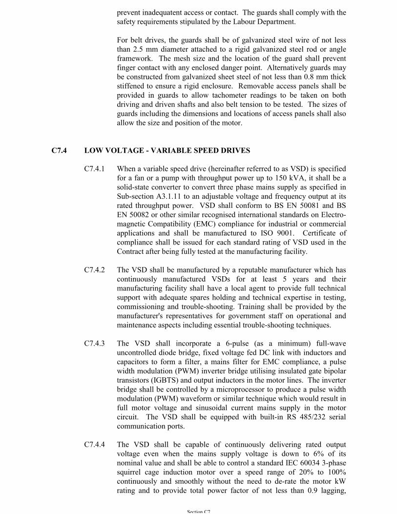
Section C7
prevent inadequatent access or contact. The guards shall comply with thesafety requirements stipulated by the Labour Department.
For belt drives, the guards shall be of galvanized steel wire of not lessthan 2.5 mm diameter attached to a rigid galvanized steel rod or angleframework. The mesh size and the location of the guard shall preventfinger contact with any enclosed danger point. Alternatively guards maybe constructed from galvanized sheet steel of not less than 0.8 mm thickstiffened to ensure a rigid enclosure. Removable access panels shall beprovided in guards to allow tachometer readings to be taken on bothdriving and driven shafts and also belt tension to be tested. The sizes ofguards including the dimensions and locations of access panels shall alsoallow the size and position of the motor.
C7.4 LOW VOLTAGE - VARIABLE SPEED DRIVES
C7.4.1 When a variable speed drive (hereinafter referred to as VSD) is specifiedfor a fan or a pump with throughput power up to 150 kVA, it shall be asolid-state converter to convert three phase mains supply as specified inSub-section A3.1.11 to an adjustable voltage and frequency output at itsrated throughput power. VSD shall conform to BS EN 50081 and BSEN 50082 or other similar recognised international standards on Electro-magnetic Compatibility (EMC) compliance for industrial or commercialapplications and shall be manufactured to ISO 9001. Certificate ofcompliance shall be issued for each standard rating of VSD used in theContract after being fully tested at the manufacturing facility.
C7.4.2 The VSD shall be manufactured by a reputable manufacturer which hascontinuously manufactured VSDs for at least 5 years and theirmanufacturing facility shall have a local agent to provide full technicalsupport with adequate spares holding and technical expertise in testing,commissioning and trouble-shooting. Training shall be provided by themanufacturer's representatives for government staff on operational andmaintenance aspects including essential trouble-shooting techniques.
C7.4.3 The VSD shall incorporate a 6-pulse (as a minimum) full-waveuncontrolled diode bridge, fixed voltage fed DC link with inductors andcapacitors to form a filter, a mains filter for EMC compliance, a pulsewidth modulation (PWM) inverter bridge utilising insulated gate bipolartransistors (IGBTS) and output inductors in the motor lines. The inverterbridge shall be controlled by a microprocessor to produce a pulse widthmodulation (PWM) waveform or similar technique which would result infull motor voltage and sinusoidal current mains supply in the motorcircuit. The VSD shall be equipped with built-in RS 485/232 serialcommunication ports.
C7.4.4 The VSD shall be capable of continuously delivering rated outputvoltage even when the mains supply voltage is down to 6% of itsnominal value and shall be able to control a standard IEC 60034 3-phasesquirrel cage induction motor over a speed range of 20% to 100%continuously and smoothly without the need to de-rate the motor kWrating and to provide total power factor of not less than 0.9 lagging,
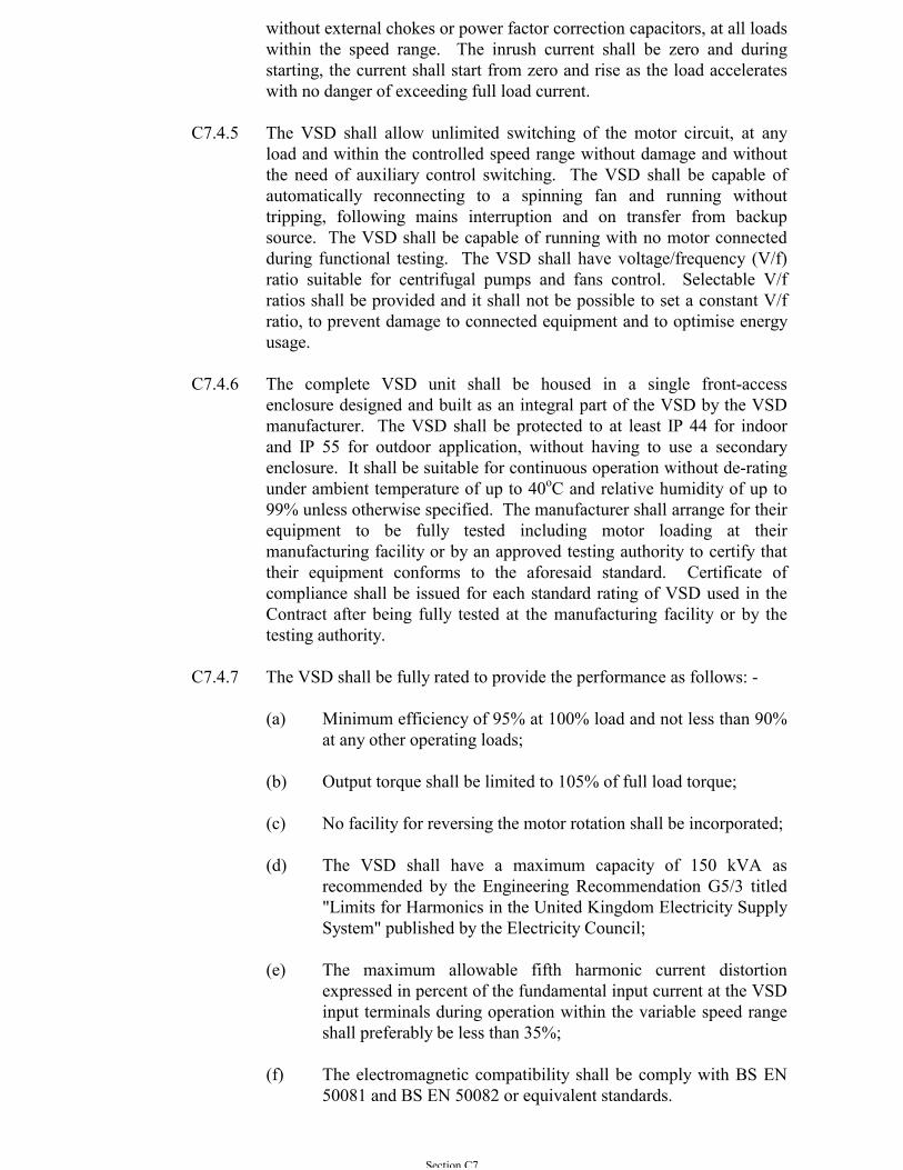
Section C7
without external chokes or power factor correction capacitors, at all loadswithin the speed range. The inrush current shall be zero and duringstarting, the current shall start from zero and rise as the load accelerateswith no danger of exceeding full load current.
C7.4.5 The VSD shall allow unlimited switching of the motor circuit, at anyload and within the controlled speed range without damage and withoutthe need of auxiliary control switching. The VSD shall be capable ofautomatically reconnecting to a spinning fan and running withouttripping, following mains interruption and on transfer from backupsource. The VSD shall be capable of running with no motor connectedduring functional testing. The VSD shall have voltage/frequency (V/f)ratio suitable for centrifugal pumps and fans control. Selectable V/fratios shall be provided and it shall not be possible to set a constant V/fratio, to prevent damage to connected equipment and to optimise energyusage.
C7.4.6 The complete VSD unit shall be housed in a single front-accessenclosure designed and built as an integral part of the VSD by the VSDmanufacturer. The VSD shall be protected to at least IP 44 for indoorand IP 55 for outdoor application, without having to use a secondaryenclosure. It shall be suitable for continuous operation without de-ratingunder ambient temperature of up to 40oC and relative humidity of up to99% unless otherwise specified. The manufacturer shall arrange for theirequipment to be fully tested including motor loading at theirmanufacturing facility or by an approved testing authority to certify thattheir equipment conforms to the aforesaid standard. Certificate ofcompliance shall be issued for each standard rating of VSD used in theContract after being fully tested at the manufacturing facility or by thetesting authority.
C7.4.7 The VSD shall be fully rated to provide the performance as follows: -
(a) Minimum efficiency of 95% at 100% load and not less than 90%at any other operating loads;
(b) Output torque shall be limited to 105% of full load torque;
(c) No facility for reversing the motor rotation shall be incorporated;
(d) The VSD shall have a maximum capacity of 150 kVA asrecommended by the Engineering Recommendation G5/3 titled"Limits for Harmonics in the United Kingdom Electricity SupplySystem" published by the Electricity Council;
(e) The maximum allowable fifth harmonic current distortionexpressed in percent of the fundamental input current at the VSDinput terminals during operation within the variable speed rangeshall preferably be less than 35%;
(f) The electromagnetic compatibility shall be comply with BS EN50081 and BS EN 50082 or equivalent standards.
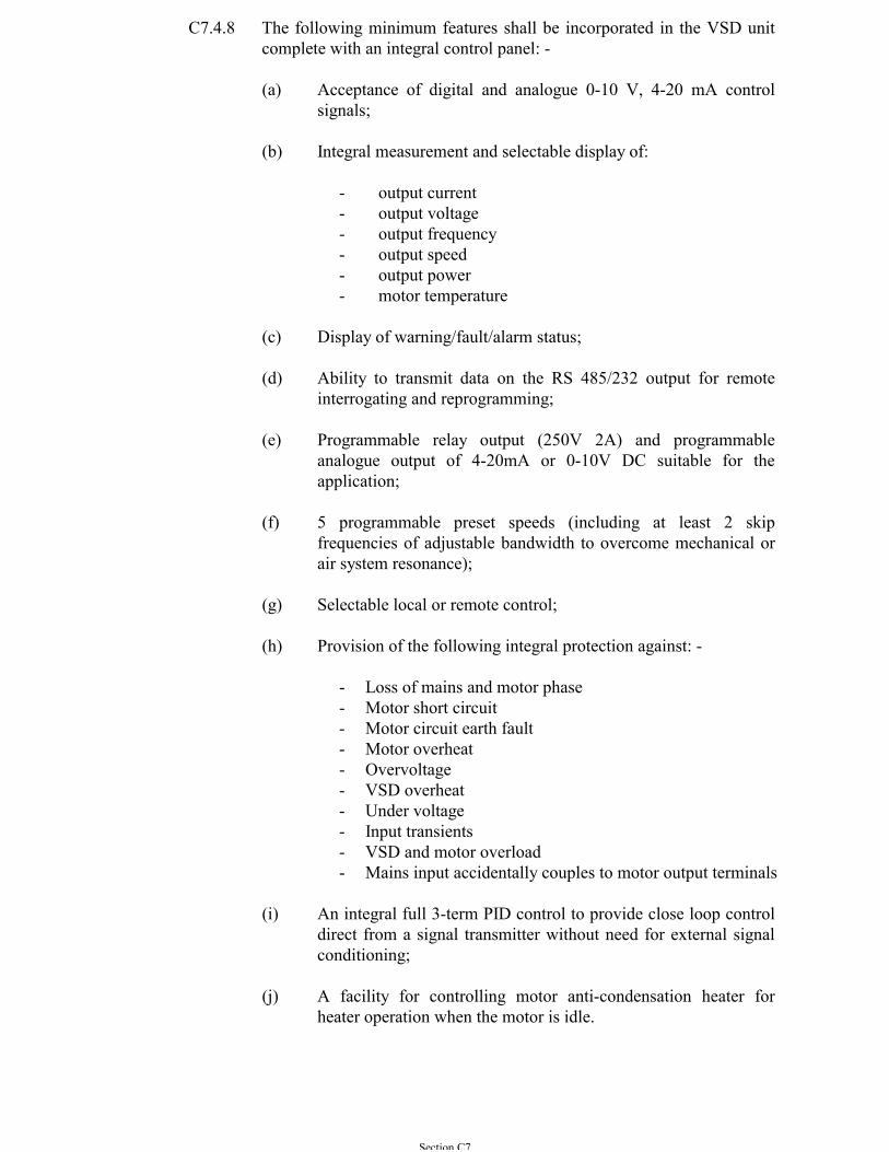
Section C7
C7.4.8 The following minimum features shall be incorporated in the VSD unitcomplete with an integral control panel: -
(a) Acceptance of digital and analogue 0-10 V, 4-20 mA controlsignals;
(b) Integral measurement and selectable display of:
- output current- output voltage- output frequency- output speed- output power- motor temperature
(c) Display of warning/fault/alarm status;
(d) Ability to transmit data on the RS 485/232 output for remoteinterrogating and reprogramming;
(e) Programmable relay output (250V 2A) and programmableanalogue output of 4-20mA or 0-10V DC suitable for theapplication;
(f) 5 programmable preset speeds (including at least 2 skipfrequencies of adjustable bandwidth to overcome mechanical orair system resonance);
(g) Selectable local or remote control;
(h) Provision of the following integral protection against: -
- Loss of mains and motor phase- Motor short circuit- Motor circuit earth fault- Motor overheat- Overvoltage- VSD overheat- Under voltage- Input transients- VSD and motor overload- Mains input accidentally couples to motor output terminals
(i) An integral full 3-term PID control to provide close loop controldirect from a signal transmitter without need for external signalconditioning;
(j) A facility for controlling motor anti-condensation heater forheater operation when the motor is idle.
Section C7
C7.5 LOW VOLTAGE - MOTOR SWITCHGEAR, STARTER AND CONTROLPANELS
C7.5.1 General
Motor switchgear, starters and controls shall be supplied and installed toperform the operation and control of the air-conditioning equipment to beprovided. The starters and controls shall be housed in wall-mountedlocal motor control panels, or floor-standing motor control switchboardsas indicated in the Contract Documents. The control panels orswitchboards shall incorporate all control devices, timers, accessoriesand wiring necessary for proper operation.
C7.5.2 Local Motor Control Panels
(a) The local motor control panel shall be of wall-mounted factorybuilt assemblies of low voltage switchboard housing the motorstarter and switchgear.
(b) The panel shall be Partially Type-Tested Assemblies (PTTA) asdefined in IEC 439-1 and constructed generally to Form 2.
(c) The panel shall be of steel construction, self supporting, withmodular top, side and back panels and doors of sheet steel builtup on substantial framing with all necessary stiffeners, supportsand return edges to provide a rigid construction and clearaccessibility to all internal components within the panel. Thethickness of the sheet steel shall be at least 1.6 mm.
(d) The panel enclosure shall be of degree of protection of IP 44 forindoor application to IEC 529. All doors shall have hinges andbe provided with dust-excluding gasket.
(e) All panels shall, but not be limited to, include the followingoperational features: -
- Local Auto/On/Off switch for each equipment,- A starter for each motor,- Fuse switch or circuit breaker for each equipment,- Isolating switch for each main incoming supply and for each
motor starter,- Protective, control and auxiliary relays,- Current transformer,- Current ammeter for each equipment with phase selection
switch for each motor,- Voltmeter for panel with power supply of 60 A or above,- Hour run meter,- Indicating lamps, push buttons, selectors and control
switches,- Emergency stop push buttons,- Labelling.
Section C7
Unless otherwise specified, the components above shall complywith the requirements stipulated in the Electrical GeneralSpecification.
C7.5.3 Motor Control Switchboard
The motor control switchboard (hereafter called the “Switchboard”) shallbe a free-standing floor-mounted low voltage switchboard to groupcentrally the motor starters, controls and switchgear for the air-conditioning and ventilation equipment etc.
The Switchboard shall, but not be limited to, include the followingprovisions: -
- Local Auto/On/Off switch for each equipment- Air circuit breaker, fuse switch and/or moulded case circuit breaker- Busbars- Isolating switch for each main incoming supply and for each motor
starter- A starter for each motor- Protective, control and auxiliary relays- Current transformer- Current ammeter for each equipment with phase selection switch for
each motor- Voltmeter for panel with power supply of 60 A or above- Hour run meter- Indicating lamps, push buttons, selector and control switches- Emergency stop push buttons- Labelling
Unless otherwise specified, the Switchboard and associated componentsabove shall comply with the requirements stipulated in the ElectricalGeneral Specification.
C7.5.4 Motor Starters
(a) General Requirements
(i) Motor starters shall generally comply with therequirements of the Electrical General Specification andwith the BS EN 60947-4-1 or IEC 292 standard.
(ii) The duty of the starters shall be suitable for themechanical and electrical duties imposed by the motorsbeing switched and in particular, the starting torque,current, starting time and frequency of operation.
(iii) Motor of more than 0.5 kW rating shall be provided witha starter designed to perform the following functionsefficiently and safely: -
- To start the motor without damage to the drive ordriven equipment whilst regulating the starting current
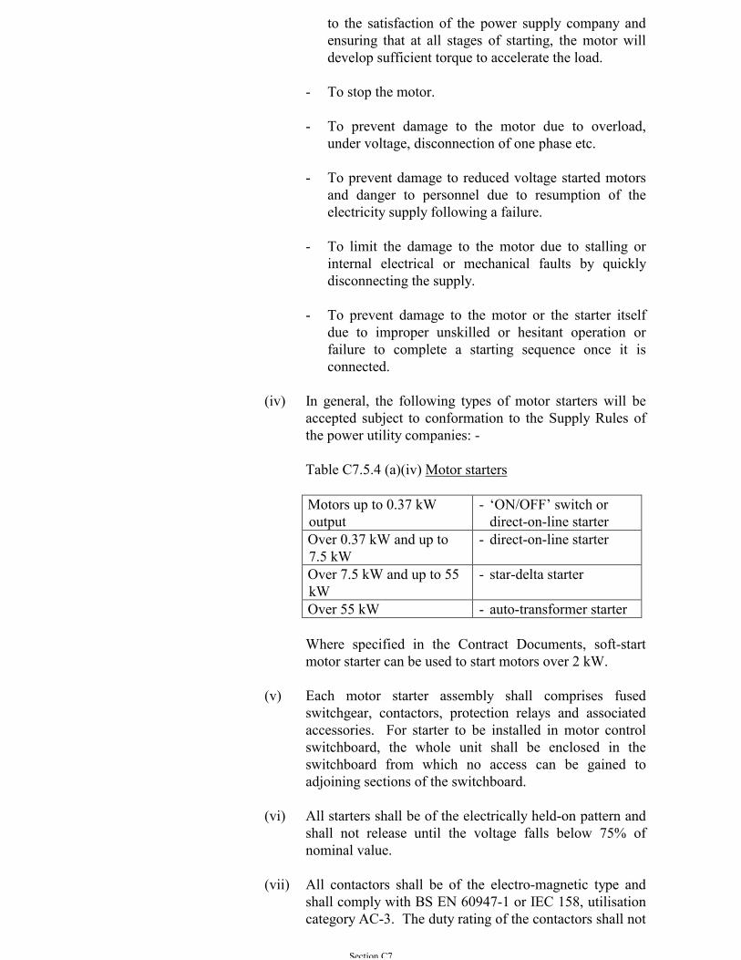
Section C7
to the satisfaction of the power supply company andensuring that at all stages of starting, the motor willdevelop sufficient torque to accelerate the load.
- To stop the motor.
- To prevent damage to the motor due to overload,under voltage, disconnection of one phase etc.
- To prevent damage to reduced voltage started motorsand danger to personnel due to resumption of theelectricity supply following a failure.
- To limit the damage to the motor due to stalling orinternal electrical or mechanical faults by quicklydisconnecting the supply.
- To prevent damage to the motor or the starter itselfdue to improper unskilled or hesitant operation orfailure to complete a starting sequence once it isconnected.
(iv) In general, the following types of motor starters will beaccepted subject to conformation to the Supply Rules ofthe power utility companies: -
Table C7.5.4 (a)(iv) Motor starters
Motors up to 0.37 kWoutput
- ‘ON/OFF’ switch ordirect-on-line starter
Over 0.37 kW and up to7.5 kW
- direct-on-line starter
Over 7.5 kW and up to 55kW
- star-delta starter
Over 55 kW - auto-transformer starter
Where specified in the Contract Documents, soft-startmotor starter can be used to start motors over 2 kW.
(v) Each motor starter assembly shall comprises fusedswitchgear, contactors, protection relays and associatedaccessories. For starter to be installed in motor controlswitchboard, the whole unit shall be enclosed in theswitchboard from which no access can be gained toadjoining sections of the switchboard.
(vi) All starters shall be of the electrically held-on pattern andshall not release until the voltage falls below 75% ofnominal value.
(vii) All contactors shall be of the electro-magnetic type andshall comply with BS EN 60947-1 or IEC 158, utilisationcategory AC-3. The duty rating of the contactors shall not
Section C7
be less than intermittent duty class 0.1 60% on-loadfactor.
(viii) Control circuits shall be operated on main supply derivedfrom the control panel or switchboard, and protected byfuse to BS 88: Part 2.
(ix) Where duplicate equipment is provided, the starter foreach equipment shall be housed in a separate panel.Unless otherwise indicated, where an equipment isprovided with duplicate motors, two starters shall besupplied; a single starter with a local changeover switchwill not be accepted.
(b) Direct-on-line (DOL) Starters
(i) Motors rated below 7.5kW shall be direct-on-lineprovided that the maximum starting current does notexceed six times the rated motor full load current,otherwise star-delta starters shall be provided.
(ii) The starters shall, but not be limited to, include thefollowing: -
- Fused switchgear.
- Triple pole air break contactor.
- A triple pole motor protection unit incorporating over-current and single-phasing protection with manualreset facilities. The over-current protection unit shallbe of the thermal type, with minimum setting of 110% of full load current.
- Under-volt release protection device. Unlessotherwise specified, it shall be arranged to provideautomatic restart on restoration of mains voltage.
- Current transformers with suitable ratio, output andaccuracy for motor protection.
- Local/off/remote control selector switch lockable ineach position.
- Start and stop push buttons.
- Indicating lamps for motor running, off and tripped onfault.
- Dry contacts wired to terminals for remote indicationof motor running, off, tripped on fault and summaryalarm to supervisory control panels.
Section C7
- Terminals wired to provide for connection toemergency stop push button and remote start/stop ofthe motor.
- Hour run meter.
- Lamp test button.
- Any other items required to effect satisfactory motorstarting and control as specified elsewhere in theSpecification.
(c) Star-delta Starters
(i) Motors rated at and above 7.5kW and up to 55kW shall bestar-delta started to limit the maximum starting current towithin 2.5 times the rated motor full load current.
(ii) Star-delta starters shall be equipped as per DOL startersspecified above, with the following additional provisions:-
- Triple pole air break contactors with electrical andmechanical interlock arranged for automatic star-deltatransition.
- Calibrated and adjustable solid state timer forautomatic star-delta transition.
- A triple pole motor protection unit incorporating over-current, single-phasing and earth leakage protectionwith manual reset facilities. The over-currentprotection unit shall be of the thermal type, with aminimum setting of 110% of full load current. Theearth leakage protection unit shall be selected toisolate the motor circuit with a maximum faultdisconnection time of 5 seconds in case of earthleakage without causing nuisance tripping of themotor circuit due to motor starting and transientcurrent transformer saturation.
(d) Auto-transformer Starters
(i) Motors rated above 55kW shall be reduced voltage startedby means of auto-transformer to limit the maximumstarting current to within 2.5 times the rated motor fullload current.
(ii) Reduced voltage starters shall be equipped as per star-delta starters specified above, with the followingadditional provisions: -
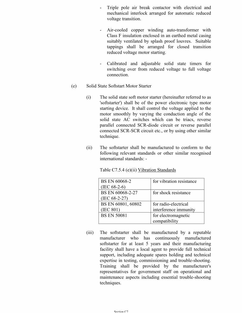
Section C7
- Triple pole air break contactor with electrical andmechanical interlock arranged for automatic reducedvoltage transition.
- Air-cooled copper winding auto-transformer withClass F insulation enclosed in an earthed metal casingsuitably ventilated by splash proof louvres. Suitabletappings shall be arranged for closed transitionreduced voltage motor starting.
- Calibrated and adjustable solid state timers forswitching over from reduced voltage to full voltageconnection.
(e) Solid State Softstart Motor Starter
(i) The solid state soft motor starter (hereinafter referred to as'softstarter') shall be of the power electronic type motorstarting device. It shall control the voltage applied to themotor smoothly by varying the conduction angle of thesolid state AC switches which can be triacs, reverseparallel connected SCR-diode circuit or reverse parallelconnected SCR-SCR circuit etc., or by using other similartechnique.
(ii) The softstarter shall be manufactured to conform to thefollowing relevant standards or other similar recognisedinternational standards: -
Table C7.5.4 (e)(ii) Vibration Standards
BS EN 60068-2(IEC 68-2-6)
for vibration resistance
BS EN 60068-2-27(IEC 68-2-27)
for shock resistance
BS EN 60801, 60802(IEC 801)
for radio-electricalinterference immunity
BS EN 50081 for electromagneticcompatibility
(iii) The softstarter shall be manufactured by a reputablemanufacturer who has continuously manufacturedsoftstarter for at least 5 years and their manufacturingfacility shall have a local agent to provide full technicalsupport, including adequate spares holding and technicalexpertise in testing, commissioning and trouble-shooting.Training shall be provided by the manufacturer'srepresentatives for government staff on operational andmaintenance aspects including essential trouble-shootingtechniques.
Section C7
(iv) Full technical details of the softstarter provided by themanufacturer shall be submitted and shall cover at leastthe following: -
- Technical guide on its applications,- Schematic and wiring drawings, down to circuit board
level where possible,- Shop drawings and as-fitted drawings,- Operation manuals with commissioning guide,- Maintenance manuals with trouble-shooting guide
and,- Parts list and recommended spare parts with price.
(v) Degree of Protection of Enclosure
The softstarter shall be protected to at least IP44 forindoor and IP55 for outdoor application by a single front-access enclosure and shall be suitable for operationwithout derating under ambient temperature of up to 40oC and relative humidity of up to 99%.
(vi) Voltage and Power Rating
Unless otherwise specified, the rated operational voltageshall be as specified in Sub-section A3.1.11. The ratedpower and quantities of the softstarters shall be asindicated in the Particular Specification or the Drawings.
(vii) Mode of Operation
The softstarter shall provide the following modes ofoperation and shall be transitionless without causing anycurrent inrush and torque surges during operation:-
- Voltage ramp - The motor voltage shall begin initiallyat a preset 'start voltage' and increase to line voltage ata preset 'ramp rate'. The acceleration ramp time shallbe adjustable up to 30 sec.
- Current limitation - It shall be capable of limiting themaximum starting current which shall be adjustableup to 5 times of rated current.
- Soft stop - A deceleration voltage ramp shall beapplied to the motor for applications which require anextended coast to rest. The voltage ramp down timeshall be adjustable up to 60 sec.
- Kickstart - A current pulse shall be provided in thesoftstarter to develop additional torque when startedfor loads which may need a boost to get started.
Section C7
- Energy saving - Energy saving mode shall be providedsuch that when the motor is lightly loaded or unloadedfor long periods of time, it shall automaticallydecrease motor power losses by controlling the motorterminal voltage.
- Apart from the above, other modes of operation suchas voltage pedestal starting, full voltage starting, D.C.injection braking etc. shall also be provided whenspecified in the Particular Specification.
(viii) Protection
The softstarter shall have integral protection to the motorand softstarter and LED diagnostics to aid in set-up andtroubleshooting. The protection shall include: -
- Thermal overload protection of the motor andsoftstarter,
- Mains supply protection for phase failure and phaseunbalance,
- Internal fault protection and stalled motor protection.
(ix) Auxiliary Contact
The softstarter shall provide auxiliary contacts for end ofstarting (by-pass) and fault condition. The output relaycontact shall be suitable for 220 V AC operation incategory AC11 and DC operation in category DC11.
(x) Selection of Softstarter and Operating Precautions
- The starting current-speed transition curve of theselected softstarter shall closely match with thestarting torque-speed characteristics of the motor andloading. The ratings of the softstarter shall base on'hot start' operation i.e. the motor shall re-startimmediately after operating at maximum rating for aperiod of time.
- The motor associated with the softstarter shall becapable of starting the driven load when supplied atreduced voltage and current. In case of severe duty,check with the motor manufacturer shall be carried outthat its derating is compatible with the operating cycleand the starting times.
- The heat sink of the softstarter shall be of good qualityaluminium construction and shall provide sufficientthermal inertia to permit successful starting of themotor without exceeding the permitted junctiontemperature of the solid state AC switches.
Section C7
- The softstarter shall be capable of continuouslydelivering rated output voltage (or reduced outputvoltage under energy saving mode) with power factorof not less than 0.9 lagging without external chokes orpower factor correction capacitors at any load. Whenusing a by-pass contactor, the order to close and openthe contactor shall be controlled by the built-in signalof the softstarter.
- The softstarter shall have the possibility to accept DCinput from external device such as ProgrammableLogic Controller (PLC) for controlling the start andstop of the unit.
- Semiconductor fuses shall be available as an optionand have the characteristics suitable to protect thesoftstarter.
- The solid state AC switches shall have a blockingvoltage of at least 1400 V for 415 V system with a rateof rise of reapplied voltage tolerance of at least 1000V per microsecond. However, an isolation contactoror isolator shall be available as an option to isolate thesupply in the 'Off ' state of the softstarter for the safetyof the operator.
- UNDER NO CIRCUMSTANCES shall all the powerfactor correction equipment be connected between thesoftstarter and the motor. If power factor correctionequipment is employed, it shall be connected to thesupply side of the softstarter.
C7.6 LOW VOLTAGE - AUTOMATIC POWER FACTOR CORRECTIONCAPACITORS
Power factor correction capacitor equipment including capacitors, cables, cableglands, control relays, trunking, control wiring, current transformers etc. shall beprovided such that the overall power factor at the motor control switchboard isimproved to not less than 0.85. The net rating of each capacitor bank shall becalculated and be suitable for operating at 380 V, 3 phase, 50 Hz.
The capacitor bank shall be of the wall or floor mounting cubicle-type, built upfrom static primary capacitor unit. The capacitor bank together with its associatedequipment shall not be installed inside the switchboard, where practicable.However, if it is unavoidable due to physical constraint, the equipment shall beinstalled in a separate compartment segregated from the rest of the switchboard.
The static primary capacitor unit shall be of the hermetically sealed dry type andmanufactured from continuous reel metal foil and high quality tissue. This staticprimary capacitor unit shall comply with the requirements of IEC 60070. Oil typecapacitors will be rejected.
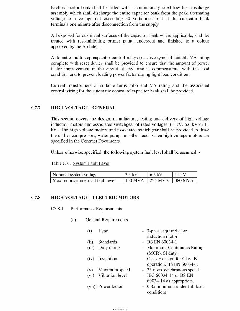
Section C7
Each capacitor bank shall be fitted with a continuously rated low loss dischargeassembly which shall discharge the entire capacitor bank from the peak alternatingvoltage to a voltage not exceeding 50 volts measured at the capacitor bankterminals one minute after disconnection from the supply.
All exposed ferrous metal surfaces of the capacitor bank where applicable, shall betreated with rust-inhibiting primer paint, undercoat and finished to a colourapproved by the Architect.
Automatic multi-step capacitor control relays (reactive type) of suitable VA ratingcomplete with reset device shall be provided to ensure that the amount of powerfactor improvement in the circuit at any time is commensurate with the loadcondition and to prevent leading power factor during light load condition.
Current transformers of suitable turns ratio and VA rating and the associatedcontrol wiring for the automatic control of capacitor bank shall be provided.
C7.7 HIGH VOLTAGE - GENERAL
This section covers the design, manufacture, testing and delivery of high voltageinduction motors and associated switchgear of rated voltages 3.3 kV, 6.6 kV or 11kV. The high voltage motors and associated switchgear shall be provided to drivethe chiller compressors, water pumps or other loads when high voltage motors arespecified in the Contract Documents.
Unless otherwise specified, the following system fault level shall be assumed: -
Table C7.7 System Fault Level
Nominal system voltage 3.3 kV 6.6 kV 11 kVMaximum symmetrical fault level 150 MVA 225 MVA 380 MVA
C7.8 HIGH VOLTAGE - ELECTRIC MOTORS
C7.8.1 Performance Requirements
(a) General Requirements
(i) Type - 3-phase squirrel cageinduction motor
(ii) Standards - BS EN 60034-1(iii) Duty rating - Maximum Continuous Rating
(MCR), SI duty.(iv) Insulation - Class F design for Class B
operation, BS EN 60034-1.(v) Maximum speed - 25 rev/s synchronous speed.(vi) Vibration level - IEC 60034-14 or BS EN
60034-14 as appropriate.(vii) Power factor - 0.85 minimum under full load
conditions
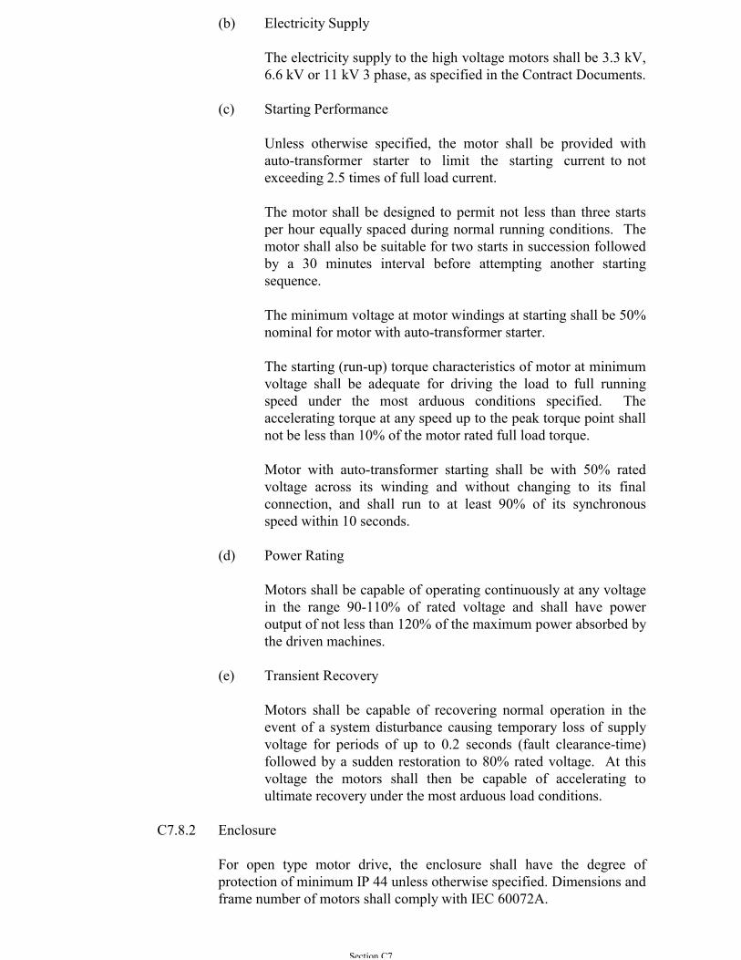
Section C7
(b) Electricity Supply
The electricity supply to the high voltage motors shall be 3.3 kV,6.6 kV or 11 kV 3 phase, as specified in the Contract Documents.
(c) Starting Performance
Unless otherwise specified, the motor shall be provided withauto-transformer starter to limit the starting current to notexceeding 2.5 times of full load current.
The motor shall be designed to permit not less than three startsper hour equally spaced during normal running conditions. Themotor shall also be suitable for two starts in succession followedby a 30 minutes interval before attempting another startingsequence.
The minimum voltage at motor windings at starting shall be 50%nominal for motor with auto-transformer starter.
The starting (run-up) torque characteristics of motor at minimumvoltage shall be adequate for driving the load to full runningspeed under the most arduous conditions specified. Theaccelerating torque at any speed up to the peak torque point shallnot be less than 10% of the motor rated full load torque.
Motor with auto-transformer starting shall be with 50% ratedvoltage across its winding and without changing to its finalconnection, and shall run to at least 90% of its synchronousspeed within 10 seconds.
(d) Power Rating
Motors shall be capable of operating continuously at any voltagein the range 90-110% of rated voltage and shall have poweroutput of not less than 120% of the maximum power absorbed bythe driven machines.
(e) Transient Recovery
Motors shall be capable of recovering normal operation in theevent of a system disturbance causing temporary loss of supplyvoltage for periods of up to 0.2 seconds (fault clearance-time)followed by a sudden restoration to 80% rated voltage. At thisvoltage the motors shall then be capable of accelerating toultimate recovery under the most arduous load conditions.
C7.8.2 Enclosure
For open type motor drive, the enclosure shall have the degree ofprotection of minimum IP 44 unless otherwise specified. Dimensions andframe number of motors shall comply with IEC 60072A.

Section C7
The motor frame shall be designed to facilitate easy removal of rotorassembly and to permit access from both motor ends for cleaning andrewinding of the stator winding and replacement of the complete statorcore assembly.
The motor shall be provided with suitable arrangement to facilitate liftingand handling during erection and overhaul.
C7.8.3 Thermal Insulation & Characteristics
The motor windings and accessories shall be designed for Class Finsulation with Class B maximum temperature limit to BS EN 60034-1.
Natural rubber insulated cables shall not be used between the statorwindings and motor terminals.
C7.8.4 Motor Stators & Windings
The motor winding insulation shall withstand voltage stress caused byswitching of motor starter using SF6 circuit breaker, vacuum circuitbreaker or vacuum contactor.
Motors shall be designed to permit high voltage tests in accordance withBS EN 60034-1 to be conducted after erection on site.
End windings shall be rigidly braced to prevent their movement at thespecified service duty.
The insulation system of stator windings shall be of the resin-rich type orthe vacuum pressure impregnated type. Windings shall be given asurface treatment where necessary to prevent deterioration resulting fromadverse environmental conditions and for corona shield.
Winding coils shall be of the pre-formed type. Random-wound typewindings and hair-pin type windings are not acceptable. Stator slotsshall be of the open type to facilitate easy insertion of replacementwindings.
C7.8.5 Rotor
Unless otherwise specified, the rotor shall have cage type copper/copperalloy winding.
The limits of vibration shall comply with IEC 60034-14 or BS EN60034-14 as appropriate.
The rotor shall be dynamically balanced at its rated speed or a speed notless than 600 rpm to confirm that vibration levels are within the specifiedlimit. Means for fixing balancing weights in-situ shall be provided atboth ends of the rotor without the need to dismantle the motor forbalancing on site.
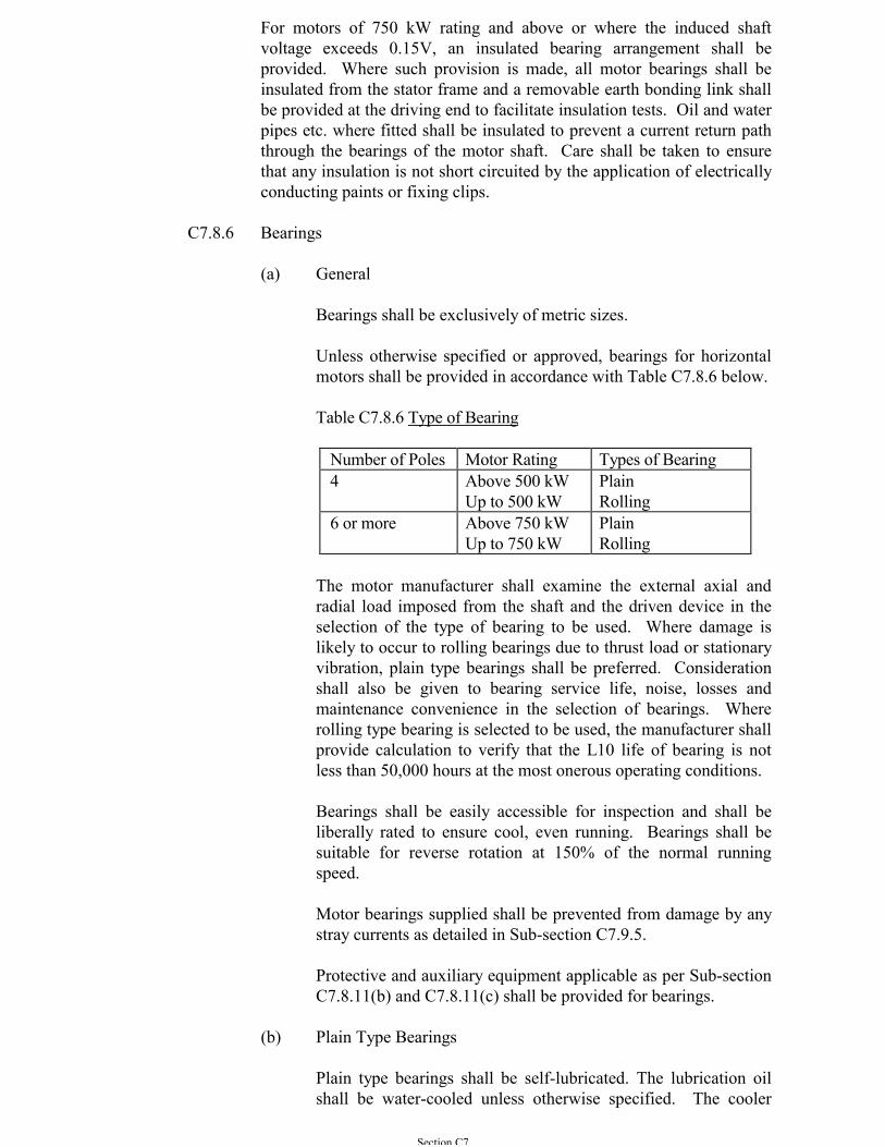
Section C7
For motors of 750 kW rating and above or where the induced shaftvoltage exceeds 0.15V, an insulated bearing arrangement shall beprovided. Where such provision is made, all motor bearings shall beinsulated from the stator frame and a removable earth bonding link shallbe provided at the driving end to facilitate insulation tests. Oil and waterpipes etc. where fitted shall be insulated to prevent a current return paththrough the bearings of the motor shaft. Care shall be taken to ensurethat any insulation is not short circuited by the application of electricallyconducting paints or fixing clips.
C7.8.6 Bearings
(a) General
Bearings shall be exclusively of metric sizes.
Unless otherwise specified or approved, bearings for horizontalmotors shall be provided in accordance with Table C7.8.6 below.
Table C7.8.6 Type of Bearing
Number of Poles Motor Rating Types of Bearing4 Above 500 kW
Up to 500 kWPlainRolling
6 or more Above 750 kWUp to 750 kW
PlainRolling
The motor manufacturer shall examine the external axial andradial load imposed from the shaft and the driven device in theselection of the type of bearing to be used. Where damage islikely to occur to rolling bearings due to thrust load or stationaryvibration, plain type bearings shall be preferred. Considerationshall also be given to bearing service life, noise, losses andmaintenance convenience in the selection of bearings. Whererolling type bearing is selected to be used, the manufacturer shallprovide calculation to verify that the L10 life of bearing is notless than 50,000 hours at the most onerous operating conditions.
Bearings shall be easily accessible for inspection and shall beliberally rated to ensure cool, even running. Bearings shall besuitable for reverse rotation at 150% of the normal runningspeed.
Motor bearings supplied shall be prevented from damage by anystray currents as detailed in Sub-section C7.9.5.
Protective and auxiliary equipment applicable as per Sub-sectionC7.8.11(b) and C7.8.11(c) shall be provided for bearings.
(b) Plain Type Bearings
Plain type bearings shall be self-lubricated. The lubrication oilshall be water-cooled unless otherwise specified. The cooler
Section C7
shall be such as to avoid any electrolytic action or corrosion.Bearings shall be designed to exclude the ingress of dust andwater and adequately sealed to prevent leakage of oil.
The water pipes shall not run over or adjacent to the HV terminalboxes and shall not impede access to the bearing for inspection.The initial filling of bearing lubricating oil shall be supplied anddelivered in an oil drum.
Bearings shall be provided with a filling hole, an air breather, anaccessible drain plug and a clearly visible oil level indicator toshow oil levels during running and at standstill. Sight levelindicators of the type fitted externally to the bearing shall bedesigned to prevent rotation about the gland connection.
Besides the normal running operation, the lubrication shall alsobe adequate during starting and running down periods.
The bearing design shall avoid oil being drawn into the windingthrough the shaft by centrifugal force or the effect of ventilationfan.
The bearing mounting bracket assembly shall be capable ofcompletely detached from the stator, viz. no welding to the statorframe shall be permitted.
Bearing pads shall be self aligning in design, and shall notrequire any jacking screws for adjustment.
(c) Rolling Type Bearings
Rolling type bearings shall be adequately lubricated by greaseand sealed against leakage of lubricant along the shaft.Construction shall be such that bearings can be dismantled andreassembled without risk of damage.
The bearing assembly shall be designed to prevent the entry ofdust or water. It shall be provided with a separate grease nippleto serve each lubricating point and a grease relief device suchthat when the motor runs at its rated speed any surplus grease isejected out of the bearing casing to a separate container.
Housings for ball/roller bearings shall be packed with approvedlithium-based grease at the time of assembly. The required re-lubrication interval shall be more than 4,000 hours.
Grease nipples, oil cups and dip sticks shall be readily accessiblewithout removal of guarding. Where necessary for accessibility,nipples shall be remotely mounted at a point as near as ispracticable to the lubrication point.
C7.8.7 Motor Foundation
Section C7
A motor bedplate/foundation block shall be provided unless the motor isto be mounted on the soleplate of the compressor.
C7.8.8 Provision for Cabling and Termination
(a) Cabling Provision at Bedplates
Provision shall be made in the steel bedplate where necessary tofacilitate straight run of cable to the bottom of the motor cableterminal box.
(b) Cabling Provision at Cable Boxes
Unless otherwise specified or approved, the cable terminal boxfor the motor shall be positioned at the side of the motor. Cableentry shall be from below for all box types unless otherwisespecified.
An earthing terminal with the same current carrying capacity asthe line terminals with the minimum size suitable for 25 x 6mm copper strip shall be provided. A tapped hole with screwexternal to the cable box would be acceptable.
Permanent terminal marking and direction of rotation inaccordance with BS 4999 Part 108 shall be provided in the cableboxes.
(c) Cabling Provision at Motor Casing
The terminal leads from cable box terminals or connectors to thewindings for a distance of 150 mm beyond their point of entryinto the motor frame, shall be adequately braced to withstand theforces produced by maximum fault current.
The phase windings shall be accessible for testing. For thispurpose, neutral leads shall be brought out to a separate star-point terminal box and shorted with an insulated copper bar ofcross-sectional area not less than the conductor of the terminallead.
Studs shall be so fixed as to prevent the terminal leads fromturning when the nuts are tightened down. Means shall beprovided to prevent slackening of cable connections due tovibration.
(d) Motor Supply Cables
Motor terminations shall be suitable for connection of highvoltage power supply cables which shall be cross linkedpolyethylene insulated, PVC-sheathed, galvanised steel wire andPVC covered XLPE/SWA/PVC copper cables as specified inSub-section C7.12.
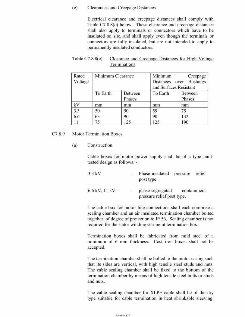
Section C7
(e) Clearances and Creepage Distances
Electrical clearance and creepage distances shall comply withTable C7.8.8(e) below. These clearance and creepage distancesshall also apply to terminals or connectors which have to beinsulated on site, and shall apply even though the terminals orconnectors are fully insulated, but are not intended to apply topermanently insulated conductors.
Table C7.8.8(e) Clearance and Creepage Distances for High VoltageTerminations
RatedVoltage
Minimum Clearance Minimum CreepageDistances over Bushingsand Surfaces Resistant
To Earth BetweenPhases
To Earth BetweenPhases
kV mm mm mm mm3.36.611
506375
5090125
5990125
75132190
C7.8.9 Motor Termination Boxes
(a) Construction
Cable boxes for motor power supply shall be of a type fault-tested design as follows: -
3.3 kV - Phase-insulated pressure reliefpost type
6.6 kV, 11 kV - phase-segregated containmentpressure relief post type.
The cable box for motor line connections shall each comprise asealing chamber and an air insulated termination chamber boltedtogether, of degree of protection to IP 56. Sealing chamber is notrequired for the stator winding star point termination box.
Termination boxes shall be fabricated from mild steel of aminimum of 6 mm thickness. Cast iron boxes shall not beaccepted.
The termination chamber shall be bolted to the motor casing suchthat its sides are vertical, with high tensile steel studs and nuts.The cable sealing chamber shall be fixed to the bottom of thetermination chamber by means of high tensile steel bolts or studsand nuts.
The cable sealing chamber for XLPE cable shall be of the drytype suitable for cable termination in heat shrinkable sleeving.
Section C7
Sealing chamber shall be fitted with a horizontal gland platesuitable for bottom cable entry.
The termination chamber shall have an insulated assembly andbe fitted with 3 stud terminals in insulating mouldings of epoxyresin, glass fibre, polyester or approved similar material.Porcelain insulators shall not be used. Cable-coupler typeterminals shall not be acceptable.
Front access detachable cover plates shall be fixed by studs andnuts. Separate plates shall be supplied for sealing andtermination chambers.
Joints shall be machined flat and fitted with neoprene rubbergaskets.
(b) Termination Box Auxiliaries
Brass cable glands shall be provided for motor supply cables.Cable lugs shall be supplied for the motor supply cable. Unlessspecial lugs are used in the short circuit type test, cable lug shallbe of the compression type manufactured from tin-platedseamless copper tubing with single bolt palm terminal. Thecable lug shall be type-tested to BS 4579 Part 1 withdimensions conforming to BS 91 Table 2.
C7.8.10 Markings and Data Plates
An instruction and a data plate, of stainless steel, brass or other approvednon-tarnishing metal shall be provided. The instruction plate shall givethe connections and phase rotation for the required direction of rotation.The required direction of rotation shall be marked on the motor.
The data plate shall be stamped with the information required by BS EN60034-1. Data plates on which the above required information is onlypainted will not be accepted.
The motor serial number shall be stamped with metal dies on the drivingend shaft face of the motor in addition to being stamped on the stator.
C7.8.11 Temperature Detectors for Motor Protection
(a) Embedded Temperature Detectors (ETD)
Unless otherwise specified, embedded temperature detectors oflinear characteristics, e.g. thermocouple or resistancethermometer, and complete with monitoring unit shall beprovided to offer protection against over-heating on load andstalling of the motor. Resistance temperature detector (RTD)shall comply with Grade 2 of BS EN 60751 or IEC 60751.
At least two detectors of the same characteristics suitablyembedded in the stator shall be installed, positioned at points at
Section C7
which the highest temperatures are likely to occur, e.g. onedetector between coil sides within the slots, one detector underthe coils at the bottom of the slots and one detector between thecoils and slot wedges. Detector leads shall be wired to anauxiliary cable box such that any ETD may be isolated fortesting.
The ETD monitoring unit for each motor shall have thefollowing features: -
(i) Alarm contacts to operate at a temperature of 120ºCwhich is adjustable for individual detecting elements.
(ii) Trip contacts to operate at a temperature of 140ºC whichis adjustable for individual detecting elements.
(iii) A common digital temperature gauge and selectionbuttons for reading the winding temperatures of theindividual detecting elements.
(b) Temperature Detectors for Bearings
A temperature detector shall be installed for each bearing forhigh temperature alarm and trip operation.
Unless recommended otherwise by the motor manufacturer,alarms detectors shall operate 10°C lower than the trip detectors.
Insulated thermometer pockets shall be provided to enable easyinsertion or removal of a temperature detector. Dial typethermometers or digital indicators, with independently adjustablealarm and trip contacts, shall be provided at the motor controlswitchboard to monitor the bearing temperatures. Contacts shallbe arranged to close for alarm indication or tripping and shall beso arranged that the operation of the alarm or tripping may bechecked manually.
(c) Bearing Coolant Failure Detector
Where water cooled bearings are used a flow failure detectorshall be provided.
Suitable timers and relays shall be provided to obviate any falsealarm during the starting up of the motor set or on flow surges.
C7.9 HIGH VOLTAGE - MOTOR CONTROL SWITCHBOARDS
C7.9.1 General Requirements
(a) The motor control switchboards shall be of the single busbar,indoor air-insulated, metalclad type formed into completeswitchboards. The high voltage switchgear and switchboards
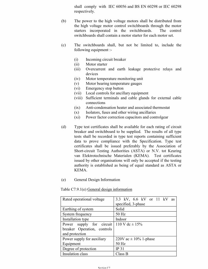
Section C7
shall comply with IEC 60056 and BS EN 60298 or IEC 60298respectively.
(b) The power to the high voltage motors shall be distributed fromthe high voltage motor control switchboards through the motorstarters incorporated in the switchboards. The controlswitchboards shall contain a motor starter for each motor set.
(c) The switchboards shall, but not be limited to, include thefollowing equipment :-
(i) Incoming circuit breaker(ii) Motor starter(iii) Overcurrent and earth leakage protective relays and
devices(iv) Motor temperature monitoring unit(v) Motor bearing temperature gauges(vi) Emergency stop button(vii) Local controls for ancillary equipment(viii) Sufficient terminals and cable glands for external cable
connections(ix) Anti-condensation heater and associated thermostat(x) Isolators, fuses and other wiring ancillaries(xi) Power factor correction capacitors and controlgear
(d) Type test certificates shall be available for each rating of circuitbreaker and switchboard to be supplied. The results of all typetests shall be recorded in type test reports containing sufficientdata to prove compliance with the Specification. Type testcertificates shall be issued preferably by the Association ofShort-circuit Testing Authorities (ASTA) or N.V. tot Keuringvan Elektrotechnische Materialen (KEMA). Test certificatesissued by other organisations will only be accepted if the testingauthority is established as being of equal standard as ASTA orKEMA.
(e) General Design Information
Table C7.9.1(e) General design information
Rated operational voltage 3.3 kV, 6.6 kV or 11 kV asspecified, 3-phase
Earthing of system SolidSystem frequency 50 HzInstallation type IndoorPower supply for circuitbreaker Operation, controlsand protection
110 V dc ± 15%
Power supply for auxiliaryEquipment
220V ac ± 10% 1-phase50 Hz
Degree of protection IP 31Insulation class Class B
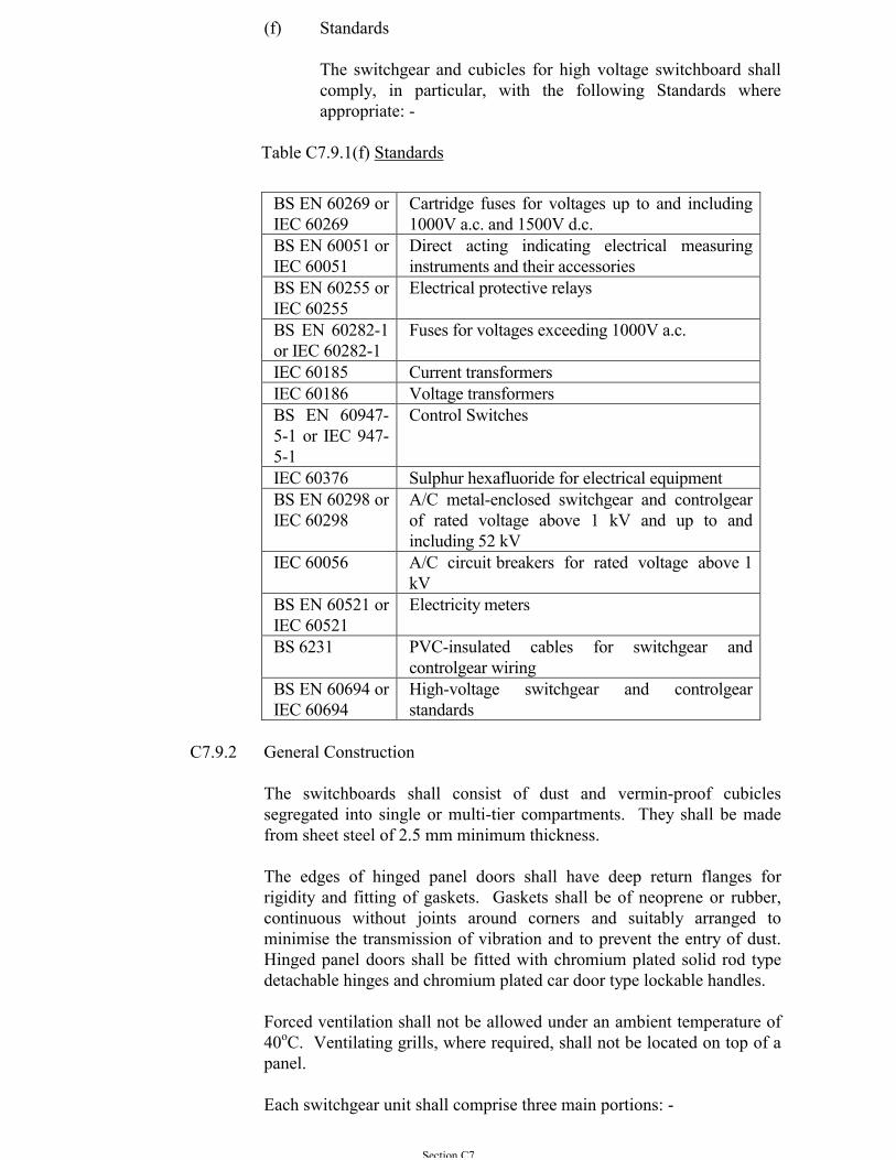
Section C7
(f) Standards
The switchgear and cubicles for high voltage switchboard shallcomply, in particular, with the following Standards whereappropriate: -
Table C7.9.1(f) Standards
BS EN 60269 orIEC 60269
Cartridge fuses for voltages up to and including1000V a.c. and 1500V d.c.
BS EN 60051 orIEC 60051
Direct acting indicating electrical measuringinstruments and their accessories
BS EN 60255 orIEC 60255
Electrical protective relays
BS EN 60282-1or IEC 60282-1
Fuses for voltages exceeding 1000V a.c.
IEC 60185 Current transformersIEC 60186 Voltage transformersBS EN 60947-5-1 or IEC 947-5-1
Control Switches
IEC 60376 Sulphur hexafluoride for electrical equipmentBS EN 60298 orIEC 60298
A/C metal-enclosed switchgear and controlgearof rated voltage above 1 kV and up to andincluding 52 kV
IEC 60056 A/C circuit breakers for rated voltage above 1kV
BS EN 60521 orIEC 60521
Electricity meters
BS 6231 PVC-insulated cables for switchgear andcontrolgear wiring
BS EN 60694 orIEC 60694
High-voltage switchgear and controlgearstandards
C7.9.2 General Construction
The switchboards shall consist of dust and vermin-proof cubiclessegregated into single or multi-tier compartments. They shall be madefrom sheet steel of 2.5 mm minimum thickness.
The edges of hinged panel doors shall have deep return flanges forrigidity and fitting of gaskets. Gaskets shall be of neoprene or rubber,continuous without joints around corners and suitably arranged tominimise the transmission of vibration and to prevent the entry of dust.Hinged panel doors shall be fitted with chromium plated solid rod typedetachable hinges and chromium plated car door type lockable handles.
Forced ventilation shall not be allowed under an ambient temperature of40oC. Ventilating grills, where required, shall not be located on top of apanel.
Each switchgear unit shall comprise three main portions: -
Section C7
(a) Separate chambers at the top of the switchboard housing thebusbars, current transformers and voltage transformers, and shallbe accessible through bolted covers only,
(b) A compartment housing the relays and instruments,
(c) A moving portion comprising a carriage complete with circuitbreaker. The circuit breaker shall preferably be arranged forvertical isolation from the busbars.
The circuit breaker compartment shall be accessible through a hingeddoor fitted with a glazed window for viewing the circuit breakermechanical status indicators.
The relay and instrument compartment shall be located at the front ofeach switchgear unit and shall be provided with a hinged door for accessto the internal wiring and terminals. Moulded gaskets of non-agingmaterial shall be used to provide close sealing. The height of theinstrument panel above floor level shall not exceed 2400 mm. All panelsconstituting a complete switchboard shall be of equal height.
Bolted-on rear and top covers shall be designed to gain access toindividual circuits without exposing other circuits which may be alive.Switchboards shall not be located across floor expansion joints.
Before steelworks is painted, it shall be treated and degreased by anapproved method such as grit blasting to ISO 8501-1 or chemicalpickling and an approved anti-rusting priming coat applied. The panelsshall be externally finished in semi-gloss stoved enamel or cellulose to acolour to be approved by the Architect.
C7.9.3 Primary Busbars and Connections
Primary busbars and connections between the several pieces of apparatusforming the equipment of a switchboard shall be of high conductivitycopper to BS 1433. Construction, marking and arrangement of busbars,connections and auxiliary wiring shall be to BS EN 60298 or IEC 60298and BS 159.
Primary busbars shall be contained in a separate compartments within theswitchboard and access shall be possible only by means of bolted-onsheet steel covers which shall clearly be marked 'BUSBARS'. Busbarsand busbar connections shall not be exposed when covers and doors areopened for access to the remainder of the switchgear. Busbars shall bereadily extensible.
Each phase conductor of the primary busbars including all through jointsand tapping connections shall, in addition to being spaced at suchintervals as to give the necessary air clearance for the voltage rating, shallbe epoxy encapsulated solid copper bars. Joints shall be insulated withmoulded removable insulated covers. Taping shall not be accepted.
Section C7
Primary busbars, connections and their supports shall be capable ofcarrying the short-time current associated with their short-circuit ratingsfor a period of 3 seconds.
Where busbar supports use insulation of moulded or resin bondedmaterial, it shall have a durable anti-hygroscopic surface finish with highanti-tracking properties.
The connections from busbars in individual units shall have a continuouscurrent rating of not less than that of the equipment comprising the unit.
At all points where connections or joints occur, the busbars andconnecting pieces shall be tinned or silver-plated. The resistance of anylength of conductor containing a joint shall not be greater than that of anequal length without a joint.
Jointing of sections of busbars shall be done by mechanical means.Soldered, braced, welded or riveted joints shall not be used in busbars.Jointing faces of copper conductors shall be tinned or silver plated, orapplied with other approved treatment to maintain effective conductivityof the joint. All necessary busbar jointing bolts, nuts, and fixingaccessories shall be provided. The recommended torque for tighteningthe bolts shall be stated in the maintenance manual.
Primary busbars and connections shall be clearly marked and shall bedisplaced for standard phase sequence Red (R), Yellow (Y) and Blue (B)counting from front to rear, top to bottom, or left to right as viewed fromthe switching device operating mechanism side to BS EN 60298 or IEC60298.
C7.9.4 Circuit Breakers
(a) General
Unless otherwise specified, the 11 kV circuit breaker units shallbe of the vacuum type complying with IEC 60056, and the 3.3kV or 6.6 kV circuit breaker units shall be of the vacuum type orthe sulphur hexafluoride (SF6) type complying with IEC 60056.They shall be of a design with vertical isolation, horizontalwithdrawal facilities.
The moving portion of each circuit breaker unit shall consist of athree-pole circuit breaker with operating mechanism, primaryand secondary disconnecting devices, auxiliary switches, positionindicators and the necessary control wiring all mounted on asubstantial steel framework. The framework and all metal part ofthe moving portion apart from current carrying parts, shall besolidly earthed via the fixed portion. The earthing of the movingportion shall be to the approval of the Architect. Means ofregistration shall be provided so that circuit breakers may bereadily placed and secured in the correct position in the fixedportion.
Section C7
Circuit breakers of the same current and voltage rating shall befully interchangeable with one another. Means shall be providedto prevent circuit breakers from being placed into fixed housingsof different ratings. This device shall also prevent damage toisolating and other contacts.
(b) Vacuum Circuit Breakers
For vacuum circuit breakers, means of confirming the validity ofvacuum by the occurrence of flash-over when a voltage is appliedbetween the vacuum interrupter contacts shall be included in themaintenance tools. Vacuum leakage shall be monitored toinitiate an alarm and it shall not be possible to close a circuitbreaker when vacuum leakage is serious enough to threaten safeoperation of the switchgear.
Vacuum circuit breakers for motor circuits shall incorporatesurge suppressers to minimise the effects of switching transientvoltage on the motor insulation.
(c) SF6 circuit breakers
A pressure switch shall be provided on the SF6 gas compartmentto monitor the gas pressure. The system of gas monitoring shallbe temperature compensated.
Alarm and lockout feature shall be incorporated. Alarm signalshall be initiated and the breaker shall be inhibited from closingwhenever the gas pressure drops below a preset level. Thecircuit breaker shall be prevented from operation. Means shall beprovided in the gas compartment for the connection of serviceequipment and for the topping up of the gas.
The circuit breaker shall be suitable to interrupt its rated normalcurrent with SF6 gas at atmospheric pressure. The sealing of thegas compartment shall be designed so that there is no need forthe SF6 gas to be replenished within reasonable periods. The gasleakage shall not exceed 1% per annum at site ambienttemperature.
An external contact indicator shall be provided to check theextent of contact wear. Means shall also be provided to allowaccess to the contacts of the interrupter units for necessaryinspection and maintenance. All contact assemblies shall bereplaceable. Safeguards shall be provided to prevent incorrectreplacement of contacts.
The designed electrical and mechanical life shall be at least 5,000and 10,000 cycles respectively. The circuit breaker shall becapable of undergoing 40 cycles of fault breaking operations at50% rated short-circuit breaking current or equivalent withoutany need of opening up the tank for inspection or contactreplacement.
Section C7
Instructions for post-fault maintenance, gas top-up contact andseal replacement shall be clearly detailed in the manual.
(d) Operating Mechanisms
The circuit breaker operating mechanism shall be of thefollowing types as specified: -
- Stored energy operation by means of a manuallycharged spring with mechanical release.
- Stored energy operation by means of a motor-chargedspring with manual and electrical release.
- Solenoid operated.
The mechanism shall be of the trip free type so that the circuitbreaker shall be free to open during the closing operationimmediately its tripping device operates. The circuit breakershall be capable of closing fully and latching against its ratedmaking current.
Spring operated mechanisms shall have the following additionalmeasures: -
- If the circuit breaker is opened and the springs chargedthe circuit breaker shall be able to be closed and thentripped.
- If the circuit breaker is closed and the springs chargedthere shall be sufficient energy to trip, close and thentrip the circuit breaker.
- Mechanical indication and an auxiliary switch forremote electrical indication shall be provided toindicate the state of the springs.
- Motor charged mechanisms shall be provided withmeans for charging the springs by hand, and also ashrouded push button for releasing the springs. Anelectrical release coil shall also be provided.
- Under normal operation, motor recharging of theoperating springs shall commence immediately andautomatically upon completion of each circuit breakerclosing operation. The time required for springrecharged shall not exceed 30 seconds.
- It shall not be possible to close a circuit breaker, fittedwith a motor charged closing mechanism, whilst thespring is being charged. It shall be necessary for thespring to be fully charged and the associated charging
Section C7
mechanism fully prepared for closing before it can bereleased to close the circuit breaker.
All circuit breaker operating mechanism shall be fitted with anelectrical shunt trip release coil and in addition a mechanicalhand tripping device.
The electrical tripping and closing devices shall be suitable foroperation from a 110 V d.c. battery supply and but shall operatecontinuously with their coils at an ambient temperature of 40°C,over a voltage range as follow: -
- Closing solenoid 80 to 120% ofnominal voltage
- Spring charging motor 80 to 110% ofnominal voltage
- Closing release coil 80 to 110% ofnominal voltage
- Shunt trip release coil 50 to 120% ofnominal voltage
except that under battery boost charge conditions when they shallbe capable of operating at rated output and 130% of nominalvoltage for up to two hours.
All operating coils for use on the d.c. supply shall be connectedso that failure of insulation to earth does not cause the coil tobecome energised.
Tripping and closing circuits shall be provided with a fuse ineach pole on each unit and shall be independent of each other onall other circuits.
Approved, positively driven mechanically operated indicatingdevices shall be provided to indicate whether a circuit breaker isin the open or closed service, isolated or earthed position.
(e) Isolating Devices
All circuit breakers shall be connected to their associated busbarsand cables through isolating devices of an approved design toIEC 60056 and BS EN 60298 or IEC 60298 which shall bearranged for operation whilst the main circuit is live but nocurrent passing.
The design shall be such that it is impossible for the isolatingdevices to be opened by forces due to current in the primarycircuit and shall be interlocked with the circuit breaker so that itis impossible to make or break current with the isolating device.Attempted isolation shall not trip the circuit breaker.
When isolation is effected by withdrawal of the circuit breaker,provision shall be made for positively locating the circuit breaker
Section C7
in the service, isolated and, earthing positions. Stops shall beprovided to prevent over-travel and each position shall be clearlyindicated. Preferably a mechanical selector mechanism shall beutilised such that when a particular position is selected, it isimpossible to locate the circuit breaker in any other position.
Isolating devices shall incorporate self-aligning contacts, thefixed contact of which shall be such that access can readily beobtained for maintenance purposes.
(f) Overcurrent and Earth Fault Protection
All circuit breakers other than those used for controlling theincoming supply, shall have overcurrent tripping facilities to givetime delay overload current protection and instantaneous shortcircuit interruption. The time-current characteristics shall besubmitted for inspection. Shunt trip coils operated by powersupply from the mains shall not be used.
For circuit breakers controlling the incoming supply to theSwitchboard, the circuit protection shall be provided by thefollowing devices: -
- Overcurrent Protection Relay- Earth Fault Relay- Shunt-Trip Release
It shall be operated by a DC supply of 110 V obtained from thesecondary batteries complete with battery charger, etc. of suitablerating
(g) Safety Shutters
Metal shutter shall be provided to completely shroud fixedisolating contacts of the circuit breaker busbar and feedercircuits. These shutters shall be opened and closed automaticallyby the movement of the circuit breaker carriage and shall preventaccess to fixed isolating contacts when the circuit breaker iswithdrawn.
The shutters for fixed isolating contacts connected to busbars andcables shall have independent operating mechanisms. Allshutters shall have painted labels indicating whether they arebusbar or feeder shutters.
To facilitate high voltage and current injection testing viaisolating contacts, a device shall be provided for fixing, but notlocking, shutters in the open position and for releasing them tothe closed position. This device shall be arranged to bedisengaged as soon as the circuit breaker is pushed into theservice position to ensure that the automatic features of theshutters are restored.
Section C7
Self-aligning plug and socket isolating devices shall be providedfor all auxiliary circuits. The position of these devices shall besuch that individual circuits on different units are in the samerelative physical positions.
(h) Interlocking Gear
Interlocks shall be of the mechanical or key operated type andshall be provided to prevent the following operations: -
(i) A moving portion from being withdrawn from or insertedinto the isolating contacts when the circuit breaker isclosed.
(ii) The closing of the circuit breaker unless the movableportion is correctly plugged in or isolated from theequipment.
(iii) The movable portion being withdrawn or replaced unlessthe circuit breaker is isolated and in the appropriateposition.
(iv) The movable portion being plugged in without the circuitbreaker tank in position.
(v) The circuit breaker being closed in the 'SERVICE' or'EARTH' location without completing the appropriateauxiliary circuits.
(vi) To apply an earth to busbars until all circuit breakerswhich can feed the busbars, are locked open.
When key interlocking is employed, any attempt to remove thetrapped key shall not cause closing or opening of the associatedequipment.
Where a circuit breaker is fitted with means for mechanical orelectrical operation, interlocks shall be provided so that it isimpossible for the mechanical and electrical devices to operatesimultaneously.
The earthing devices shall be provided with interlocks to ensurecorrect operation in conjunction with the associated circuitbreaker.
In the case of circuit breaker earthing, the electrical tripping ofthe circuit breaker shall be rendered inoperative during earthingoperations both when closing and when closed in the earthedposition. It shall not be possible to return to the service positionand close the circuit breaker until the electrical tripping is againoperative.
Section C7
A mechanical key interlocking system shall be provided wherebyit is not possible to apply an earth to busbars until all circuitbreakers which can feed the busbar are locked open. In additionit shall not be possible to earth busbars and cable circuit at thesame time by means of the same circuit breaker.
In addition to safety interlocking which is integral to a circuitbreaker unit to prevent wrong or dangerous operation of the unititself, further interlocking shall be provided.
In general, interlocking shall be electrically isolating the closingcontactor coil circuit of a circuit breaker being interrupted unlessthe necessary conditions for closure are met. The interlockingshall be designed on a system wide basis to ensure thatsubsequent operation of a non-interlocked circuit breaker doesnot result in a set of conditions that would contradict the original'permission to close'.
(i) Interlocking Circuits
Where interlocking over a distance is required, two independentcriteria shall be used, such as absence of a voltage and remotefeeding circuit breaker open. Indication of the remote conditionshall be by single purpose circuit, care being taken that theconductors used are adequately screened and shielded tominimise both transverse and longitudinal voltages resultingfrom electromagnetic induction and differences in earth potential.The cable containing cores for interlocking circuits shall beseparate from all other multi-core cables.
All interlocking circuits shall be of the 'go and return' design, andin no instance will interconnection of batteries in differentlocations be permitted.
Where a circuit breaker is capable of manual operation inaddition to electrical operation, except where such manualoperation is possible only for maintenance purposes, key-operated interlocking shall additionally be provided, operativeonly in the instance of manual operation.
Electrical interlocks on withdrawable equipment shall bearranged so that when withdrawn, the equipment operation willbe independent of the remote interlocking contacts. In addition,the interlocks shall be such that, when the equipment iswithdrawn, the interlocking of associated apparatus is correct,and operation of the equipment in the withdrawn position willhave no effect.
(j) Locking Facilities
Locking facilities shall be provided so that the circuit breaker canbe prevented from being closed when it is open and from beingmanually tripped when it is closed. These facilities shall not
Section C7
require the fitting of any loose components prior to the insertionof the single padlock required. It shall not be possible, withoutthe aid of tools, to gain access to the tripping toggle or any partof the mechanisms which would permit defeat of the locking ofthe manual trip. It shall not be possible to lock mechanically thetrip mechanisms so as to render inoperative the electricaltripping.
In addition, the following padlocking facilities shall also beincluded: -
(i) Selector mechanisms on circuit breaker isolated andservice positions.
(ii) Safety shutters on primary contact isolating orifices inclosed position.
All switchboard access doors, other than those which areinterlocked with a switching device, shall be provided with anintegral type locking facility.
C7.9.5 Earthing and Earthing Devices
All metal parts other than those forming part of an electrical circuit shallbe connected in an approved manner to a hard drawn, high conductivitycopper earth busbar which shall run the full length of, and be bolted to,the main frame of the switchboard. At the position where joints occur,the earth busbar shall be tinned. The earth busbar shall be rated to carrycurrents equal in magnitude and duration to that associated with the shortcircuit rating of the equipment.
The design and construction of the equipment shall be such that all metalparts, other than the current carrying parts, or the withdrawal equipmentare earthed before the primary connections are made.
Metal cases supports and bases of all instruments, relays or otherassociated components mounted on the switchgear shall be connected tothe earth busbar by conductors of not less than 2.5 mm2 cross-sectionalarea.
When components are provided for mounting separately each shall beprovided with an earthing terminal of not less than 30 mm2 crosssectional area.
Earthing devices shall be provided on all circuit breaker units wherebythe circuit can be earthed. With the circuit earthed, shutters overunearthed fixed main isolating contacts shall be closed.
Busbar earthing facilities shall be provided on selected circuits of eachseparate switchboard, these circuits shall be agreed with the Architect.
Circuit and busbar earthing shall be of the transfer circuit breakerarrangement and it is preferred that the facilities shall be integral in the
Section C7
design and construction of the switchgear. Earthing devices for fitting tothe circuit breakers are acceptable but they shall be supplied in a separatecontainer together with a set of instructions for fitting and operating theequipment. Designs effecting earthing by means of a separate fault-making switch are not acceptable.
Feeder and busbar earthing devices shall have a short circuit rating equalto that of their associated circuit breaker.
Padlocking facilities shall be provided for the purpose of preventinginadvertent earthing.
Labeling shall be provided to show whether the equipment is preparedfor 'SERVICE', 'BUSBAR EARTH' or 'CIRCUIT EARTH'. Suchindication shall be visible from the front of the equipment at all times.Duplicate labels in Chinese and English shall be provided.
C7.9.6 Testing Facilities
All circuit breaker units shall be provided with facilities to enableapplied high voltage tests to be carried out.
Provision shall also be made for temporarily completing the auxiliarycircuits when the circuit breaker is isolated and if applicable, withdrawnto enable the functioning of the circuit breaker to be tested.
When current transformers and protective relays are fitted, facilities shallbe provided for primary and secondary injection tests to be carried out.
These facilities shall preferably be such that wires and connections neednot be disconnected for the tests to be carried out.
C7.9.7 Mechanical Indication
Indication shall be provided to clearly indicate whether a circuit breakeris in the open or closed service, isolated or earthed position.
Positively driven mechanical indicating devices shall be provided on allequipment to indicate the following where applicable: -
(a) Circuit breaker 'OPEN' or 'CLOSED'(b) Circuit breaker 'SPRING CHARGED' or 'SPRING FREE'
C7.9.8 Auxiliary Switches
Auxiliary switches of the double-break type and positively driven in bothdirections shall be provided on all circuit breakers and isolators forindication, control and interlocking.
Auxiliary switches shall be strong, have a positive wiping action whenclosing and shall be mounted in an accessible position clear of operatingmechanisms.
Section C7
They shall be designed to make, break and carry, without undue heating,the current of their associated circuit. Auxiliary switches shall be ratedfor 10A operational current, and shall be capable of breaking at least 2Aat 110 V d.c.
No less than eight spare auxiliary switches shall be provided with eachcircuit breaker and no less than four with each isolator. Each sparecontact shall be readily changeable from normally open to normallyclosed and vice versa. All auxiliary switches shall be wired up (viasecondary disconnecting devices if on withdrawable equipment) to aterminal board on the front of the fixed portion, arranged in the samesequence for each individual unit of the same type.
C7.9.9 Anti-Condensation Heaters
Anti-condensation heaters of an approved type shall be provided insideeach cubicle. They shall be thermostatically controlled and shall operateat black heat and shall be shrouded and located so as not to cause injuryto personnel or damage to equipment. The heaters shall be controlledfrom a double-pole miniature circuit breaker, with a lamp to indicate'cubicle heaters on'. The circuit breaker and indicating lamp shall bemounted externally at one end of the switchboard. The heaters shalloperate from 220 V 50 Hz single phase a.c. supply.
C7.9.10 Current Transformers
Current transformers shall comply with IEC 60185 and shall be suitablefor the operation of protective gear, instruments and/or meteringequipment.
Current transformers shall be of the epoxy resin encapsulated type andshall have necessary output to operate the connected protective devicesor instruments.
The primary windings shall have a short time current rating not less thanthat specified for the associated circuit breaker. The rated secondarycurrent shall be 1A or 5A.
Protection current transformers shall be of Class 10P accuracy or better.The product of rated accuracy limit factor and rated output of theprotection current transformer shall not be less than 10 times the ratedburden of the trip circuit including the relays, connection leads andovercurrent release where applicable.
Measurement current transformers shall be suitably rated and haveaccuracy Class of 3 for use with ammeters, and Class 1 for other types ofmeters.
The polarity of the primary and secondary windings of each currenttransformer shall be clearly indicated and in addition labels shall be fittedin a readily accessible position to indicate the ratio, class and duty ofeach transformer. The current transformer particulars as specified in IEC
Section C7
60185 shall be given on an accessible plate mounted external to thecurrent transformer.
All connections from secondary windings shall be brought out and takenby means of separate insulated leads to a terminal board mounted in anaccessible position. Where multi-ratio secondary windings are required,a label shall be provided at the secondary terminal board clearlyindicating the connections required for each ratio.
Current transformers for indication or metering shall have theirsecondary windings earthed at the switchgear. The secondary windingsof current transformer for protection shall be earthed at the panel whichaccommodates the associated relay. The earth connection shall be madevia a removable link.
Each current transformer shall have a certified maximum rating of atleast 1.2 times the rated current.
C7.9.11 Voltage Transformers
Voltage transformers shall comply with IEC 60186 and suitable for theoperation of protective gear, voltage regulating equipment, instrumentsand/or metering. All voltage transformers shall be of the dry type withepoxy encapsulation. The rated output per phase at a power factor 0.8lagging shall not be less than 100 VA. The rated voltage factor shall be1.2. They shall have a measuring accuracy class of 0.5 and a protectiveaccuracy class of 3P.
Voltage transformers shall be capable of carrying continuously withoutinjurious heating 50% burden above their rated burden. The ratedprimary voltage of voltage transformers shall be the appropriate nominalsystem voltage.
Unless specified otherwise, voltage transformer primary windings shallbe connected to the circuit side of the current transformers remote fromthe busbars so as to be included in the protected zone of the associatedfeeder.
The primary of a single phase voltage transformer shall be connectedacross Red and Yellow or A and B phases, unless otherwise approved.Red and Yellow phases shall be used in a synchronising scheme, unlessotherwise approved.
Voltage transformers shall be capable of being connected anddisconnected from the equipment whilst in service. Facilities forpadlocking in the service position shall be provided. Where isolating iscarried out by withdrawal, a set of shutters, capable of being padlocked,shall be provided to cover the stationary isolating contacts. The shuttersshall operate automatically by positive driven drive actuated bymovement of the voltage transformer assembly.
The primary windings shall preferably be connected via renewable fuseswith current limiting features which shall be readily accessible with the
Section C7
circuit alive and the secondary windings through fuses and links, labelledto indicate their function and phase colour, to the appropriate circuits.
For single phase voltage transformers, both ends of each secondary-winding shall be brought out to insulated links. For three phase voltagetransformers, each phase end shall be brought out to fuses, and theneutral of the secondary winding shall be brought out to insulated links.The fuses and links shall then be brought out to insulated terminalslocated in a terminal box.
The primary and secondary fuses shall be capable of being removed andreplaced when the circuit breaker is closed in the service position.Isolation of the primary fuses for this purpose shall be carried out,preferably by withdrawing the entire voltage transformer assembly.Additionally, it shall be possible to remove secondary fuses whilst thevoltage transformer is padlocked in the service location.
For single phase units, separate earth links for each secondary windingshall be provided. Each of the neutral leads shall be connected togetherat a single point and earthed as close as possible to the voltagetransformer.
Voltage transformer secondary windings shall be earthed at theswitchgear through a link which can be removed for insulation testing.
Voltage transformers having the neutral point of their higher voltagewindings earthed, shall be designed so that saturation of the core anddangerous over-heating arising therefrom shall not occur when 1.73times normal voltage is applied to each winding for a period of 15minutes.
Secondary circuits of voltage transformer shall not be parallel.
The secondary voltage connections to metering circuits shall be brokenautomatically when the circuit breaker is opened.
C7.9.12 Cables Boxes
Cable boxes shall be suitable for terminating the cables directly into theswitchgear. The dimensions and terminal arrangements, together withdetails of air insulated heat-shrinkable elastomeric PCP cabletermination, shall be submitted for approval by the Architect beforemanufacture.
All cable boxes shall be suitable for use with air insulated heat-shrinkable elastomeric PCP cable termination and shall be designed withjoint faces which will ensure leak-free operation and exclude the entry ofair, dust or moisture. The internal surfaces of cable boxes shall becleaned of all scale and rust and after cleaning and priming, shall befinished with a hard setting paint compatible with the filling medium.
Where cable boxes are provided for three-core cables, the sweatingsockets on the two outer phases shall be inclined towards the centre to
Section C7
minimise bending of the cable cores. Where there is more than one coreper phase, the socket block shall be so designed as to minimise bendingof the cable cores, and spacer clips shall be incorporated.
All cable terminals shall be of adequate size to ensure no overheatingtakes place at rated current.
The insulators and fittings shall be unaffected by atmospheric andclimatic conditions, ozone, acids or alkalis, dust deposits or rapidtemperature changes likely to arise when operating in the specified siteconditions and shall be designed so as to facilitate cleaning.
C7.9.13 Protective Relays
Unless otherwise specified, Sub-section C7.5.3 shall apply.
C7.9.14 Control and Timer Relays
Control and timer relays shall be of the plug-in type, rack mounted,provided with cable connection terminal and anchored by quick fasteningvibration-proof devices. Timer shall be of the solid-state type withproven reliability.
C7.9.15 Indicating Instruments
Unless otherwise specified, Sub-section C7.5.3 shall apply.
C7.9.16 Labels and Warning Notice
Laminated 'Traffolyte' or similar labels of ample size shall be providedfor each of the units on the switchboards engraved in English andChinese characters. Labels shall be fixed by screws on the non-detachable parts of the panel at a height of 1350 mm or above.
During the progress of manufacture of the switchboard, a schedule oflabels shall be submitted for approval by the Architect before engravingis carried out.
'Danger - H.V. Live Terminals' warning labels shall be attached to theaccess covers of the air insulated cable boxes, CT chambers and busbar,and shall be coloured red with white lettering in both English andChinese characters.
In addition to automatic screening shutters and barriers, warning labelsshall also be provided for all live parts, such as test terminal blocks.
C7.9.17 Ancillary Equipment
Battery charger/batteries system as specified in Sub-section C7.5.3 shallbe provided for the proper functions of the switchgear in theswitchboard.
Section C7
The switchboard shall be supplied complete with one hydraulic operatedhandling device suitable for handling all sizes of air circuit breakers inthe switchboard, and one set of portable earthing equipment for eachmain incoming air circuit breaker. Portable earthing leads will not beaccepted as an alternative to the earthing equipment.
The switchboard shall be supplied complete with all operating handles,jigs, etc. required for the normal charging, closing, opening, racking inand out operations of all circuit breakers of the switchboard and shall beproperly fixed in a neat manner on a board with brass hooks inside themain switch room where the switchboard is installed.
The switchboard shall be provided with two rubber mats of ribbedsurface, complying to BS921, laid in front of and at the rear of theswitchboard. The rubber mats shall be continuous sheets of 10 mmminimum thickness, each of the same length as the cubicle switchboardand a minimum width of not less than 1000 mm or the width of the spacebetween the front or back of the switchboard to the adjacent wall.
C7.9.18 Operation Diagram
For high voltage switchboards with interlocking facility, a brief operationinstruction of the switchboards together with a detailed schematic wiringdiagram, listing out all the relevant switching steps and interlocks forcommissioning/decommissioning of part or whole of the high voltageswitchboards shall be provided in a framed, transparent perspex sheetmounted adjacent to the switchboards.
C7.10 HIGH VOLTAGE - AUTO-TRANSFORMERS
C7.10.1 General
The auto-transformers for the auto-transformer motor starters shallcomply with the following specific requirements: -
(a) Type - Indoor and floor mounted type for nobreaking starting of squirrel cage 3-phase induction motor
(b) Standard - BS EN 60076 or IEC 60076(c) System Voltage - 3.3 kV, 6.6kV or 11kV as specified(d) Frequency - 50 Hz(e) Connections - Auto-star for auto-transformer starting(f) Insulation Level - 45 kV peak impulse voltage for 1/50
microsecond(g) Cooling - Natural air cooled(h) Tappings - Off load tap changers with 60%, 75%
and 85% of the line voltage to limit thestarting current to 2.5 times of full loadcurrent
Section C7
The auto-transformers shall be mounted on wheels to facilitatepositioning and removal. The transformers shall be externally finishedin semi-gloss stoved enamel or cellulose.
C7.10.2 Rating
The rating of the auto-transformer shall be designed to suit the startingduty of the motor. Motor starting time shall be taken as 10 seconds at75% or higher taps and 15 seconds at 60% or lower taps unless otherwisespecified in the Particular Specification.
C7.10.3 Insulation
(a) Insulation Medium
Unless otherwise specified, for 11 kV nominal voltage, oil-filledtransformers are preferred. Epoxy resin encapsulated auto-transformers shall be preferred for nominal voltage up to 6.6 kV.
(b) Class
Oil immersed transformer windings shall be designed for Class Einsulation for Class E operation.
Epoxy resin encapsulated transformer windings and live parts inair shall be designed for Class F or Class B insulation for Class Boperation.
(c) Coordination of equipment insulation
Table C7.10.3(c) Coordination of Equipment Insulation
Rated system voltage 12kV 7.2kV 3.6kVNominal system voltage 11kV 6.6kV 3.3kVMinimum impulse withstandvoltage (1.2kV per micro-second)
75kV 60kV 40kV
Minimum power frequencywithstand voltage (1 min)
28Hz 20Hz 10Hz
C7.10.4 Transformer Windings
All windings, terminals and connections shall be of copper. To protectwindings against high humidity, the core shall be protected by a resinencasement which shall be resistant to moisture but elastic enough towithstand the expansion and contraction caused by the loading cycles.
Impregnation shall be carried out under vacuum to obviate the presenceof any air bubbles. Means shall be employed to eliminate any partialdischarge or corona that may occur after a prolonged service period. Forepoxy resin transformers, suitable fillers shall be mixed in the epoxyresin to provide high mechanical strength and resilience to shock.
Section C7
Natural ventilation shall be used for attaining the rated output and airchannels through winding spools to attain sufficient cooling shall not beaccepted.
Internal electrical connections shall be brazed and/or fixed with bolts andnuts. Soldered or mechanically crimped joints shall not be accepted.
Core bolts where used shall be insulated from the respective magneticcircuits with material capable of withstanding a test voltage of 2000Vr.m.s. for one minute.
C7.10.5 Tap Changers
The off-load tap changers shall be accessible through the transformer topcover plate by means of copper links. The transformer top cover plateshall be fitted with an electrical and mechanical interlock designed toprevent access to the transformer tapping links until the auto-transformerstarter circuit breakers are open and the 'START' and 'RUN' circuitbreakers are in the 'CIRCUIT EARTH' position.
C7.10.6 Internal Earthing of Transformers
Metal parts of the transformer with the exception of individual corelaminations, core bolts and associated individual clamping plates shall bemaintained at some fixed potential. Where metal parts of the core areconnected to earth this shall be done by way of accessible links to allowthe insulation between core and earth to be tested. This insulation shallbe able to withstand a test voltage of 2000V r.m.s.
The magnetic circuit shall be earthed to the clamping structure at onepoint only through a removable link placed in an accessible positionbeneath an inspection opening in the tank cover. The connection to thelink shall be on the same side of the core as the main earth connection.
Where coil clamping rings are of metal at earth potential, each ring shallbe connected to the adjacent core clamping structure.
C7.10.7 Enclosure
(a) General
The enclosure shall be of rigid construction and shall not bedamaged at short-circuit faults. Exterior corners and edges shallbe rounded to give a smooth overall appearance. The design ofthe enclosure shall ensure adequate ventilation and air circulationwithout forced cooling or additional electric fans.
The enclosure shall be designed so as to allow the complete autotransformer in the tank and filled with oil, to be lifted by crane orjacks, transported by road, rail or water, skidding in any directionon plates or rails without over-straining any joints and withoutcausing subsequent leakage of oil.
Section C7
The tank or enclosure exterior shall be fitted with a M12 stud atthe bottom of the unit suitable for termination of a copperearthing bar of 32 x 3 mm.
(b) Enclosures for Epoxy Resin Cast Auto-transformers - AdditionalRequirements
Unless otherwise specified, a rectangular splash-proof enclosureof degree of protection to BS 5490, IP 32 shall be providedcovering the entire unit. The enclosure shall be sheet steel of 2mm minimum thickness and suitably braced to form a rigidstructure. The enclosure shall be bolted to the transformer frameand shall be easily removable when required. Access panels andopenings shall be provided to facilitate routine inspection andmaintenance, and changing of tap position without the need fordismantling the enclosure completely.
(c) Enclosure (Tank) for Oil-filled Auto-transformers
(i) General
A rectangular totally enclosed tank to IP 65 shall besupplied covering the entire unit.
Oil tank shall be fabricated from weldable structural steelto BS EN 10137, BS EN 10029 or products havingequivalent functions or performance, with all welding toBS EN 1011-1 or equivalent. Fabricated under bases shallbe provided with skids and detachable rollers. Theexterior of the tank shall be of plain sheet steel withoutstiffeners. Tank stiffeners shall be continuously welded.
Wherever possible the transformer tank and itsaccessories shall be designed without pockets wherein gasmay collect. All joints of the oil tank other than thosewhich may have to be broken shall be welded. Caulkingof defective welded joints will not be permitted. All jointfaces shall be designed to prevent the ingress of water orleakage of oil with a minimum of gasket surface exposedto the action of oil or air.
Unless otherwise approved, oil resisting synthetic rubbergaskets shall not be used, except where the syntheticrubber is used as a bonding medium for cork or similarmaterial.
(ii) Pressure Relief Device
Each tank shall be fitted with an approved pressure reliefdevice designed to protect the tank from damage andcontrol the explosion of oil under internal faultconditions. The device shall operate at a static pressure ofless than the hydraulic test pressure for transformer tank
Section C7
but not exceeding 70 kPa. Means shall be provided toprevent the ingress of moisture and dust.
Unless otherwise approved the relief device shall bemounted on the main tank and, if on the cover, shall befitted with a skirt projecting 25 mm inside the tank toprevent gas accumulation. If a diaphragm is used, it shallbe of approved design and material and situated above themaximum oil level.
(iii) Tank Cover
Each tank cover shall be of adequate strength, and shallnot distort when lifted. Inspection openings shall beprovided as necessary for changing tap position. Eachinspection opening shall not be less than 450 mm by 360mm and shall not weigh more than 25 kg. The tank covershall be provided with lifting welded eyes. The bolt holdsin all cover plates shall be provided with washers whichwill prevent the collection of moisture in the bolt hole.
The tank cover shall be fitted with pockets for athermometer and for the bulbs of the winding or oiltemperature indicators. Protection shall be providedwhere necessary for each capillary tube. The thermometerpocket shall be fitted with a captive screwed cap toprevent the ingress of water. The pockets shall be locatedin the position of maximum oil temperatures at full ratedpower and it shall be possible to remove the instrumentbulbs without lowering the oil level in the tank.
(iv) Transformer Auxiliaries
Each transformer shall be fitted with:
- An oil level indicator of prismatic glass visible fromground level and indicating the oil levels over therange specified. The oil level indicator shall bemarked to indicate the correct oil level with the oil at atemperature of 15ºC, 50ºC and 90ºC.
- An oil seal silica gel breather or other approved typedevice complete with dehydrating agent, indicator andsight glass. Breathers shall be at least one size largerthan the size that would be fitted in temperate climateand shall be mounted approximately 1000 mm aboveground level.
(v) Transformer Oil
The transformer oil shall comply with IEC 60296. Thefirst filling of transformer oil shall be supplied with theContract. All oil that may be used for works processing
Section C7
or testing shall be compatible with the oil to be used onsite.
(vi) Valves and Flanges
All valves up to and including 100 mm shall be ofgunmetal. Larger valves may be gunmetal or may havecast iron bodies with gunmetal fittings. They shall be ofthe full way type with internal screw and shall be openedby turning counter-clockwise when facing the handwheel.Butterfly type valves shall only be used for isolation ofradiator.
Means shall be provided for padlocking the valve in theopen and closed positions.
Every valve shall be provided with a mechanical indicatorto show clearly the position of the valve.
All valves shall be provided with flanges havingmachined faces.
Each transformer shall be fitted with the following:
- One 50 mm filter valve at the top and one 50 mmcombined filter and drain at the bottom of the tankmounted diagonally opposite to each other forconnection to oil circulating equipment,
- A robust sampling device at the top and bottom of themain tank. The sampling devices shall not be fitted onthe filter valves specified above,
- A drain valve for oil tank,
- Flanged type air release plugs as necessary.
All valves opening to atmosphere shall be fitted withblank flanges.
C7.10.8 Finishes
(a) Surface Preparation
Before untreated steelwork is painted it shall be thoroughlycleaned by an approved method such as grit blasting to ISO 8501or chemical pickling and an approved anti-rusting priming coatapplied. Treated steelwork shall be suitably cleaned anddegreased.
(b) Painting - External Surfaces
Section C7
Panel surfaces shall have not less than one primer coat, twostoved undercoats and two top stoved coats of paint. Undercoatsshall be epoxy based and easily distinguishable in shade orcolour from the priming and finishing coats. The two final coatsshall have a total minimum dry film thickness of 0.075 mm witheach coat separately stoved in an air-circulating oven. The finalpaint coating shall be of semi-matt finish and the colour shall beapproved by the Architect.
Oil tanks and other accessories shall be coated with air-dryingpaints by cold airless spray to a minimum total dry film thicknessof 0.127 mm.
Bright/gloss parts shall be protected with a coat of readilyremovable composition which shall be effective in preventingcorrosion during transport and storage.
(c) Painting - Internal Surfaces
In oil tank, interior surfaces shall be painted in an identicalmanner to the external surface with air-drying oil andpetrol-proof paint. The finishing colour of oil tank shall be red.
For epoxy resin transformer enclosures, the interior surfaces shallbe finished in white with anti-condensation paint.
C7.10.9 Rating Plates and Diagrams
The following plates shall be fixed to the transformer enclosure or tank at1700 mm average height above ground level: -
(a) A rating plate bearing the data specified in BS EN 60076 or IEC60076 and the duty rating.
(b) A diagram plate showing the internal connections and in additiona plan view of the transformer giving the correct physicalrelationship of the terminals. The percentage tapping shall beindicated for each tap.
(c) For oil immersed transformers, a plate showing the location andfunction of all valves and air release cocks or plugs. This plateshall also warn operators to refer to the Maintenance instructionsbefore applying vacuum treatment.
(d) Identification plates for the purpose of each removable inspectioncover e.g. tap changer access etc.
The above plates shall be of stainless steel or brass.
External plates and labels shall be fixed by phosphor bronze, stainlesssteel or brass screws with 3 mm thick fibre washers at the front and backof the fixing holes. Tapping holes in transformer tank walls for fixingplates will not be accepted.

Section C7
C7.10.10 Cable Boxes
The auto-transformer cable boxes complete with cable glands shall besuitable for the termination of high voltage power cables.
Cable boxes shall be air insulated and designed to suit the termination ofhigh voltage cables.
Cable boxes shall be designed to accommodate all cable joint fittings orsealing-ends required by the manufacturers of the cables, including stresscones or other approved means for grading the voltage stress on theterminal insulation of cables.
Provision for earthing the body of each cable box shall be made.
Cable boxes designed for three-core cable shall have seating sockets onthe two outer phases inclined towards the centre to minimise bending ofthe cable cores. Where there is more than one core of cable per phase,the socket block shall be so designed as to minimise bending of the cablecores.
C7.11 HIGH VOLTAGE - POWER FACTOR CORRECTION CAPACITORS
The power factor correction capacitors for the high voltage chiller motors shallimprove the overall power factor of the chiller motors to 0.95 lagging at ratedoutput power. The kVAr rating of the capacitor shall not exceed 85% of the noload magnetising kVAr of the chiller motor.
Specific requirements of the power factor correction capacitors shall be as follows:-
(a) Type - Low loss dielectric type, indoor and enclosed infloor-mounted cubicles
(b) Rated Capacity - To suit the power factor to be improved
(c) System voltage - 3.3 kV, 6.6 kV or 11 kV as specified
(d) Frequency - 50 Hz
(e) Connection - Delta-connected single-phase units
(f) Insulation Level - 45 kV peak impulse voltage for 1/50microseconds
(g) Protection - 3 line connected high voltage HBC fuses to BS2692 with striker pin
The output ratings of the power factor correction capacitor may requiremodification subject to the no-load magnetising kVAr rating of the high voltagemotors to be driven.
Section C7
The power factor correction capacitors shall be provided with combined jackingand haulage lugs to facilitate positioning. The capacitors shall be externallyfinished where applicable in semi-gloss stoved enamel or cellulose.
The power factor correction capacitors shall be protected by high voltage highbreaking capacity fuses with striker pins to BS EN 60282-1. The striker pin shallbe arranged to operate an auxiliary contact to trip the starter circuit breakers.
The power factor correction capacitor cable box complete with cable glands shallbe suitable for the termination of the high voltage power cables.
C7.12 HIGH VOLTAGE - POWER CABLES
C7.12.1 General
All 3.3 kV, 6.6 kV and 11 kV power cables shall be insulated with cross-linked polyethylene which shall comply with BS 6622 or IEC Standard502-1, and where specified, cables shall be wire armoured and finishedoverall with a continuous outer sheathing of polyvinyl chloride (PVC).
All cables shall be designed for operation on a system earthed eitherdirect or through resistance or reactance at one or more neutral points.
No straight through cable joints shall be installed without the approval ofthe Architect.
For identification the rating of the cable shall be impressed into the outerinsulation at regular intervals.
C7.12.2 Cross-Linked Polyethylene (XLPE) Cables
High voltage cross-linked polyethylene insulated (XLPE) cables shall beof the 1900/3300 V grade for 3.3 kV power cables, 3800/6600 V gradefor 6.6 kV power cables and 6350/11000 V grade for 11 kV powercables.
Multi-core cables shall comprise section-shaped circular strandedannealed copper conductors. The insulation shall consist of cross-linkedpolyethylene applied by extrusion, bedded in a minimum of two layers ofsuitable tape. Armouring, where specified, shall comprise a single layerof galvanised steel wires or aluminium strip and the cable shall be servedwith an extruded layer of PVC.
Single core cables shall comprise circular copper conductors and wherearmoured shall comprise non-magnetic aluminium wire or strip.
C7.12.3 Conductors
Copper conductors shall be stranded and shall consist of plain annealedcopper. Before stranding, the conductors shall be approximately circularin section, smooth, uniform in quality, free from scale, inequalities,
Section C7
spills, splits and other defects. There shall be no joints in the wire exceptthose made in the base rod or wire before final drawing.
The term 'annealed' signifies that the wire before stranding is capable ofat least 15 percent elongation without fracture, the test piece being notless than 150 mm and not more than 300 mm long.
The stranded conductor shall be clean and reasonably uniform in size andshape and its surface shall be free from sharp edges.
In the formation of shaped conductors containing less than 19 strands thesame number of strands shall be used as for a circular conductor ofequivalent area.
For conductors having 19 strands or more the number of strands shall bethe same as in a circular conductor of equivalent area, subject to amaximum permissible variation of plus or minus one strand. All thestrands in any given shaped conductor shall be of the same nominal size.
C7.12.4 Cable Terminations
Cables shall be terminated in approved non-ferrous mechanical glandswhich comply with BS 6121 complete with compression devices forsecuring the cable sheath. An armour clamp may be required forbonding to metal sheaths. Where the cables are installed in entirely drysituations, the gland shall be designed with a compressible gasket orpacking for securing the inner sheath and means of anchoring the armour.For cables installed wholly or partly in outdoor or damp conditionscompressible sealing and clamping features shall be provided forsecuring the inner and outer sheaths and also the armour; barriers shall beincorporated to prevent the ingress of moisture.
Section C8
SECTION C8
NOISE AND VIBRATION CONTROL
C8.1 GENERAL
This section of the Specification intends to direct the Contractor to select theappropriate and sufficient noise and vibration control measures on theplant/equipment, the interconnected piping, ductwork and conduit so that when theinstalled plant/equipment are put into operation, the resulting noise and vibrationlevels at locations within the building and at the adjacent or nearby buildings shallnot exceed the acceptable limits as promulgated by the latest statutory requirementsof the Environmental Protection Department.
The Corrected Noise Level at potential Noise Sensitive Receiver in the adjacent ornearby building, if so identified in the Particular Specification and/or Drawings,shall not exceed the Acceptable Noise Level stipulated in the TechnicalMemorandum for the Assessment of Noise from Places other than DomesticPremises, Public Places or Construction Sites issued by the EnvironmentalProtection Department when the plant/equipment installed by the Contractor are putinto operation.
C8.2 EQUIPMENT BASES
C8.2.1 General
Floor mounted equipment shall be installed on 100 mm high concretehousekeeping pads provided by the Building Contractor covering thewhole floor area requirements of the equipment bases plus a minimum of150 mm further on each side or on inverted beams at the roof. Vibrationisolators shall be mounted on this concrete pad or inverted beams.
C8.2.2 Welded Structural Steel Bases
Bases shall be constructed of adequate 'I' or channel steel membersreinforced as required to prevent the bases from flexing at start-up andfrom misalignment of drive and driven units.
All perimeter members shall be of steel sections with a minimum depthequal to 1/10th of the longest dimension of the base but need not exceed350 mm provided that the deflection and misalignment are kept withinacceptable limits as determined by the equipment manufacturer.
Height saving brackets shall be employed in all mounting locations toprovide a base clearance of 50 mm.
C8.2.3 Concrete Inertia Bases
Concrete inertia bases shall be formed within a structural steel beam orchannel frame reinforced as required to prevent flexing, misalignment of
Section C8
the drive and driven units or transferral of stresses into equipment. Thebase shall be completed with height saving brackets, concretereinforcement and equipment bolting down provisions.
In general the thickness of concrete inertia bases shall be of a minimumof 1/12th of the longest dimension of the base but never be less than 150mm. The base depth needs not exceed 300 mm unless specificallyrequired.
As an indication of the standards required, minimum thickness of theinertia base shall generally comply with the following table or be 1/12thof the longest dimension of the base, whichever is the larger: -
Table C.8.2.3 Minimum Thickness of Inertia Base
Motor Size (kW) Minimum Thickness3.7 - 11 150 mm15 - 37 200 mm45 - 55 250 mm75 - 185 300 mm
Base forms shall include minimum concrete reinforcement consisting of13 mm bars or angles welded in place on 150 mm centres running bothways in a layer of 40 mm above the bottom, or additional steel as isrequired by the structural conditions.
Unless otherwise specified, concrete inertia bases shall weigh from 2 to 3times the combined weight of the equipment/plant to be installedthereon.
Base forms shall be furnished with drilled steel members and withanchor-bolt sleeves welded below the holes where the anchor bolts fall inconcrete locations.
Height saving brackets shall be provided in all mounting locations tomaintain a base clearance of 50 mm.
C8.3 VIBRATION ISOLATORS
The following types of vibration isolation mountings or suspensions are notexhaustive but serve to cover the main types that shall be applied as appropriateunless otherwise stated in the Particular Specifications.
C8.3.1 Type 'A' - Free Standing Spring Mounts
These shall be free standing and laterally stable without any housing andcomplete with a minimum of 6.0 mm neoprene acoustical friction padsbetween the base plate and the support.
All mountings shall have levelling bolts that must be rigidly bolted to theequipment.
Section C8
Spring diameters shall be no less than 80% of the compressed height ofthe spring at rated load with a horizontal spring stiffness 1.1 times therated vertical spring stiffness.
Springs shall have a minimum additional travel to 'solid' (fullycompressed) equal to 50% of the rated deflection.
Springs shall be so designed that the ends of the springs remain parallel.
The springs selected for any given application shall be non-resonant withthe equipment's or support structure's natural frequencies. This shallapply to all springs hereafter described.
C8.3.2 Type 'B' - Restrained Spring Mounts
Equipment with operating weight different from the installed weightsuch as chillers, boilers etc. and equipment exposed to the wind such ascooling towers and other roof mounted plants shall be mounted on springmountings as Type 'A' but a housing shall be used that includes verticallimit stops to prevent spring extension when some of the weight isremoved, i.e. when the system is drained or lifted by abnormal windpressure.
C8.3.3 Type 'C' - Double Deflection Neoprene Mounts
These mountings shall have a minimum static deflection of 8.5 mm. Allmetal surfaces shall be neoprene covered to avoid corrosion and shallhave friction pads on both the top and the bottom so that they need not bebolted to the floor. Bolt holes shall be provided for applications wherebolting down is required.
C8.3.4 Type 'D' - Neoprene Pads
These mountings shall consist of 'waffle' form neoprene pads of 8.0 mmthickness. Where required these shall be adhesive cemented to 3 mmsteel plate of similar area so as to form a sandwich.
The area of pad to be used and the number of layers shall be determinedfor each application in accordance with the manufacturer'srecommendations.
C8.3.5 Type 'E' - Spring Hangers
These shall contain a steel spring located in a neoprene cup manufacturedwith a grommet to prevent short circuiting of the hanger rod.
The cup shall contain a steel washer designed to properly distribute theload on the neoprene and prevent its extrusion.
Spring diameters and hanger box lower hole sizes shall be large enoughto permit the hanger rod to swing through a 30o arc before contacting theedge of the hole and short circuiting the spring.
Section C8
Springs shall have a minimum additional travel to solid equal to 50% ofthe rated deflection.
C8.3.6 Type 'F' - Spring and Double Deflection Neoprene Hangers
These shall be as Type 'E' but incorporate a 8 mm deflection neopreneelement at the top of the hanger box.
The neoprene element shall be molded with a rod isolation bushing thatpasses through the upper part of the hanger box.
C8.3.7 Type 'G' - Pre-Compressed Spring Hangers
These shall be as Type 'F' but shall be pre-compressed to the rateddeflection so as to keep the piping or equipment at a fixed elevationduring installation.
The hangers shall be designed with a release mechanism to free thespring after the installation is completed and the hanger is subjected to itsfull load.
Deflection shall be clearly indicated by means of a scale.
C8.3.8 Type 'H' - Spring Hangers (Ductwork Support)
These shall be as Type 'E' but shall be provided with top and bottom eyebolts, the top one for bolting to the flat iron hanger strap and the bottomone for bolting to the flat iron ductwork strap.
C8.3.9 Type 'I' - Double Deflection Neoprene Hangers
These shall consist of a double deflection neoprene unit as Type 'C'which is mounted on the bottom of the hanger box.
The neoprene unit shall be molded with a rod isolation bushing thatpasses through the hanger box.
C8.3.10 Type 'J' - All Directional Anchor Units
These units shall consist of a telescopic arrangement of two sizes of steeltubing separated by a minimum 13 mm thickness of heavy duty neopreneisolation material for horizontal restraints.
Vertical restraints shall be provided by similar material arranged toprevent vertical travel in either direction.
C8.3.11 Type 'K' - Pipe Anchors and Guides
Resilient pipe anchor shall be formed by welding a steel pipe clamp tothe pipe and the clamp in turn supported at its two ends by a pair of Type'J' all directional anchor units. In this way, both the radial and axialmotion of the pipe are controlled.
Section C8
Resilient pipe guide shall be formed by welding localized longitudinalguide ribs around the pipe at location over which slides fit the oversizedpipe clamp which is in turn supported at its two ends by a pair of Type 'J'all directional anchor units. In this way, radial motion of pipe iscontrolled while axial motion of pipe is guided.
C8.3.12 Type 'M' - Split Wall/Floor Seals
These shall consist of two bolted pipe halves with 19 mm or thickerneoprene sponge bonded to the inner faces.
Seals shall project a minimum of 25 mm past either face of the walls.
Where temperatures exceed 115ºC, fiberglass shall be used in lieu of thesponge.
C8.3.13 Type 'N' - Horizontal Thrust Restrainers
Air handling equipment shall be protected where necessary againstexcessive displacement which might result from high air thrusts inrelation to the equipment weight.
The horizontal thrust restraint shall consist of a spring element located ina neoprene cup manufactured with a grommet to prevent short circuitingof the threaded rod. The thrust assembly shall be so designed that thespring element can be preseted for thrust at the factory and adjusted atthe site to allow for a maximum of 6 mm movement at start and stop.
The assembly shall be furnished with one threaded rod and two anglebrackets for attachment to both the equipment and ductwork or theequipment and the structure. Horizontal restraints shall be attached at thecentre line of thrust and symmetrically on either side of the unit.
C8.3.14 Type 'O' - Built in Inertia Block Plant Support
Where specified in the Contract Document, the Contractor (or theBuilding Contractor) shall provide plant foundations and housekeepingpads in the form of large concrete blocks recessed into the main floorslab.
Unless otherwise indicated, the sides and bottom of the embeddedportion of the concrete block shall be lined with a minimum of 50 mmthick 'load bearing' cork pad to the following specification.
Table C8.3.14 Density of Vibration Isolators
DensityDesignation
Density(kg/m3)
Loading(kg/m2)
Light Medium
3.0 – 4.55.5 – 6.0
250 - 2500 2500 - 20000
Section C8
Heavy 7.0 – 7.5 15000 - 30000
C8.4 PLANT/EQUIPMENT VIBRATION ISOLATION
C8.4.1 General
All vibration isolators shall have their known undeflected heights orcalibration markings so that, after adjustment when carrying their loads,the deflection under load can be verified, thus determining that the loadis within the proper range of the device and that correct degree ofvibration isolation is being achieved according to the design.
The static deflection of the isolator at each support point shall not differfrom the design objective for the equipment as a whole by more than ±10%.
The ratio of lateral to vertical stiffness for spring shall be not less than0.9 nor greater than 1.5 .
All neoprene mountings shall have hardness of 40 to 65 durometer, afterminimum aging of 20 days or corresponding over-aging.
In order to resist corrosion, all vibration isolation mountings and hangersshall be treated as follows: -
(a) Springs to be neoprene coated or hot dip galvanized.
(b) Wearing hardware to be cadmium plated steel or stainless steel ofan appropriate grade.
(a) All other metal parts to be hot dip galvanized.
For any Contract, all vibration isolators and associated equipment basesshall whenever possible be of the product of a single manufacturer.Acceptable manufacturer's systems shall strictly comply with the designintent of this and/or the Particular Specification.
C8.4.2 Selection Guide for Equipment Base and Vibration Isolator
Unless otherwise specified, the selection of the type of equipment baseand vibration isolator (mounting/hanger) for different plant/equipmentand on different floor spans and levels shall follow the requirements asindicated in the Selection Guide for Vibration Isolation (Table 42 of thelatest edition of ASHRAE Applications Handbook) and the staticdeflection of the vibration isolator selected shall either provide aminimum isolation efficiency of 90% in ground floor areas and 95% inupper level areas or be not less than the corresponding values shown inTable 42. However, the Contractor shall be responsible to ensure that theselected vibration isolation system is suitable for the specificplant/equipment and the specific building structure on which theplant/equipment is mounted.
Section C8
The Contractor shall provide more efficient isolation than thosesuggested in Table 42 in case if the adjacent occupied space is a noisecritical area such as board room and executive office. Advice fromvibration isolator manufacturer shall be sought if necessary.
C8.5 PIPEWORK VIBRATION ISOLATION
C8.5.1 Flexible Connectors
Flexible connector shall consist of a single or twin-sphere bodymanufactured with reinforced rubber, the ends of which are raised andwire reinforced to form the cuffs for sealing purposes. The cuffs shall bebacked by floating steel flanges.
The rubber body shall be reinforced by multi-layered nylon tire cordfabric.
Flexible connectors shall have a life in excess of 10 years under thedesign working conditions.
The rubber membranes shall have an indelible identification system toclearly identify the model and hence suitability for the application andworking conditions and have the date of manufacture moulded into thecover to ensure that no units that have exceeded the recommended shelflife are used.
Straight connectors shall be of the twin-sphere construction whilst elbowconnectors shall be of the single-sphere construction.
Straight connectors connected to resiliently supported equipment shall beequipped with acoustical control cables to prevent excessive elongationof the connectors if the system operating pressure is in excess of thevalue recommended by the manufacturer for use without control cables.
Acoustical control cable assembly shall consist of four large triangleanchor plates, two control cables with large swedged-on end fittings and13 mm thick acoustical washer bushings of sufficiently large loadbearing area to isolate the end fittings, axially and laterally.
C8.5.2 Flexible Metallic Hose
Allowable stress levels should be within BS 5500 : 1985.
The corrugated seamless hose body shall be of the annular and closepitched type.
For all ferrous applications, the hose body and the braid shall bemanufactured from stainless steel material to BS 1449 Part 2 Type32lS31. End terminations shall be carbon steel threaded male nipples toBS 21 (BSP) for 65 mm size and below and flanges to BS 4504 NPStandard for 75 mm and above.
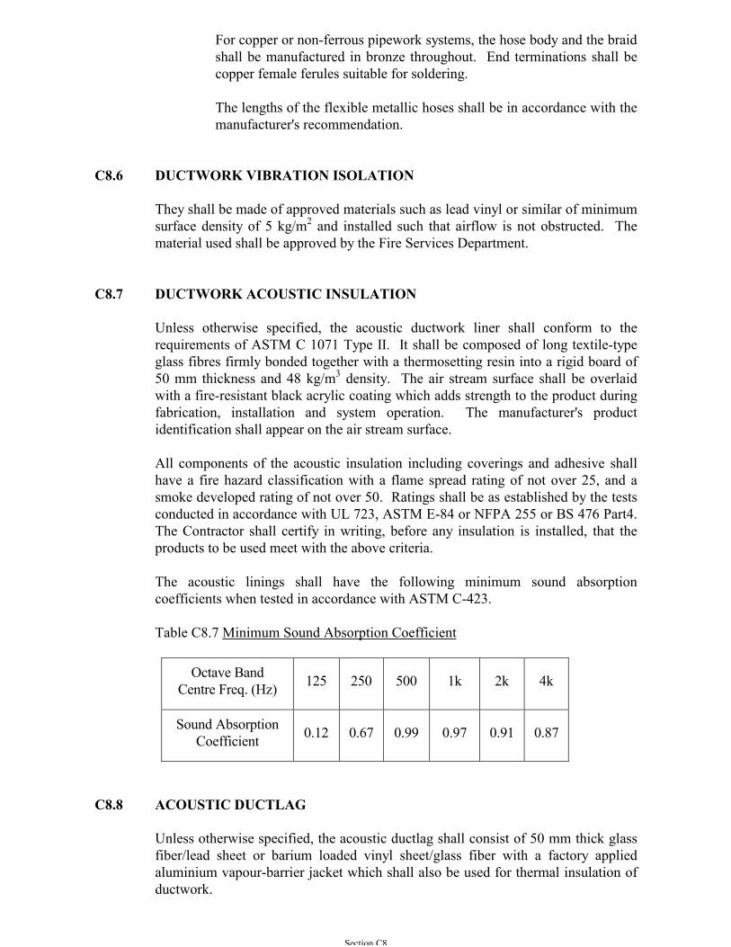
Section C8
For copper or non-ferrous pipework systems, the hose body and the braidshall be manufactured in bronze throughout. End terminations shall becopper female ferules suitable for soldering.
The lengths of the flexible metallic hoses shall be in accordance with themanufacturer's recommendation.
C8.6 DUCTWORK VIBRATION ISOLATION
They shall be made of approved materials such as lead vinyl or similar of minimumsurface density of 5 kg/m2 and installed such that airflow is not obstructed. Thematerial used shall be approved by the Fire Services Department.
C8.7 DUCTWORK ACOUSTIC INSULATION
Unless otherwise specified, the acoustic ductwork liner shall conform to therequirements of ASTM C 1071 Type II. It shall be composed of long textile-typeglass fibres firmly bonded together with a thermosetting resin into a rigid board of50 mm thickness and 48 kg/m3 density. The air stream surface shall be overlaidwith a fire-resistant black acrylic coating which adds strength to the product duringfabrication, installation and system operation. The manufacturer's productidentification shall appear on the air stream surface.
All components of the acoustic insulation including coverings and adhesive shallhave a fire hazard classification with a flame spread rating of not over 25, and asmoke developed rating of not over 50. Ratings shall be as established by the testsconducted in accordance with UL 723, ASTM E-84 or NFPA 255 or BS 476 Part4.The Contractor shall certify in writing, before any insulation is installed, that theproducts to be used meet with the above criteria.
The acoustic linings shall have the following minimum sound absorptioncoefficients when tested in accordance with ASTM C-423.
Table C8.7 Minimum Sound Absorption Coefficient
Octave BandCentre Freq. (Hz) 125 250 500 1k 2k 4k
Sound AbsorptionCoefficient 0.12 0.67 0.99 0.97 0.91 0.87
C8.8 ACOUSTIC DUCTLAG
Unless otherwise specified, the acoustic ductlag shall consist of 50 mm thick glassfiber/lead sheet or barium loaded vinyl sheet/glass fiber with a factory appliedaluminium vapour-barrier jacket which shall also be used for thermal insulation ofductwork.
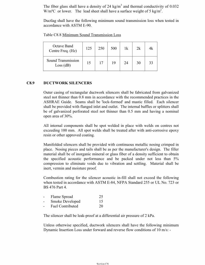
Section C8
The fiber glass shall have a density of 24 kg/m3 and thermal conductivity of 0.032W/mºC or lower. The lead sheet shall have a surface weight of 5 kg/m2.
Ductlag shall have the following minimum sound transmission loss when tested inaccordance with ASTM E-90.
Table C8.8 Minimum Sound Transmission Loss
Octave BandCentre Freq. (Hz) 125 250 500 1k 2k 4k
Sound TransmissionLoss (dB) 15 17 19 24 30 33
C8.9 DUCTWORK SILENCERS
Outer casing of rectangular ductwork silencers shall be fabricated from galvanizedsteel not thinner than 0.8 mm in accordance with the recommended practices in theASHRAE Guide. Seams shall be 'lock-formed' and mastic filled. Each silencershall be provided with flanged inlet and outlet. The internal baffles or splitters shallbe of galvanized perforated steel not thinner than 0.5 mm and having a nominalopen area of 30%.
All internal components shall be spot welded in place with welds on centres notexceeding 100 mm. All spot welds shall be treated after with anti-corrosive epoxyresin or other approved coating.
Manifolded silencers shall be provided with continuous metallic nosing crimped inplace. Nosing pieces and tails shall be as per the manufacturer's design. The fillermaterial shall be of inorganic mineral or glass fiber of a density sufficient to obtainthe specified acoustic performance and be packed under not less than 5%compression to eliminate voids due to vibration and settling. Material shall beinert, vermin and moisture proof.
Combustion rating for the silencer acoustic in-fill shall not exceed the followingwhen tested in accordance with ASTM E-84, NFPA Standard 255 or UL No. 723 orBS 476 Part 4.
- Flame Spread 25- Smoke Developed 15- Fuel Contributed 20
The silencer shall be leak-proof at a differential air pressure of 2 kPa.
Unless otherwise specified, ductwork silencers shall have the following minimumDynamic Insertion Loss under forward and reverse flow conditions of 10 m/s: -
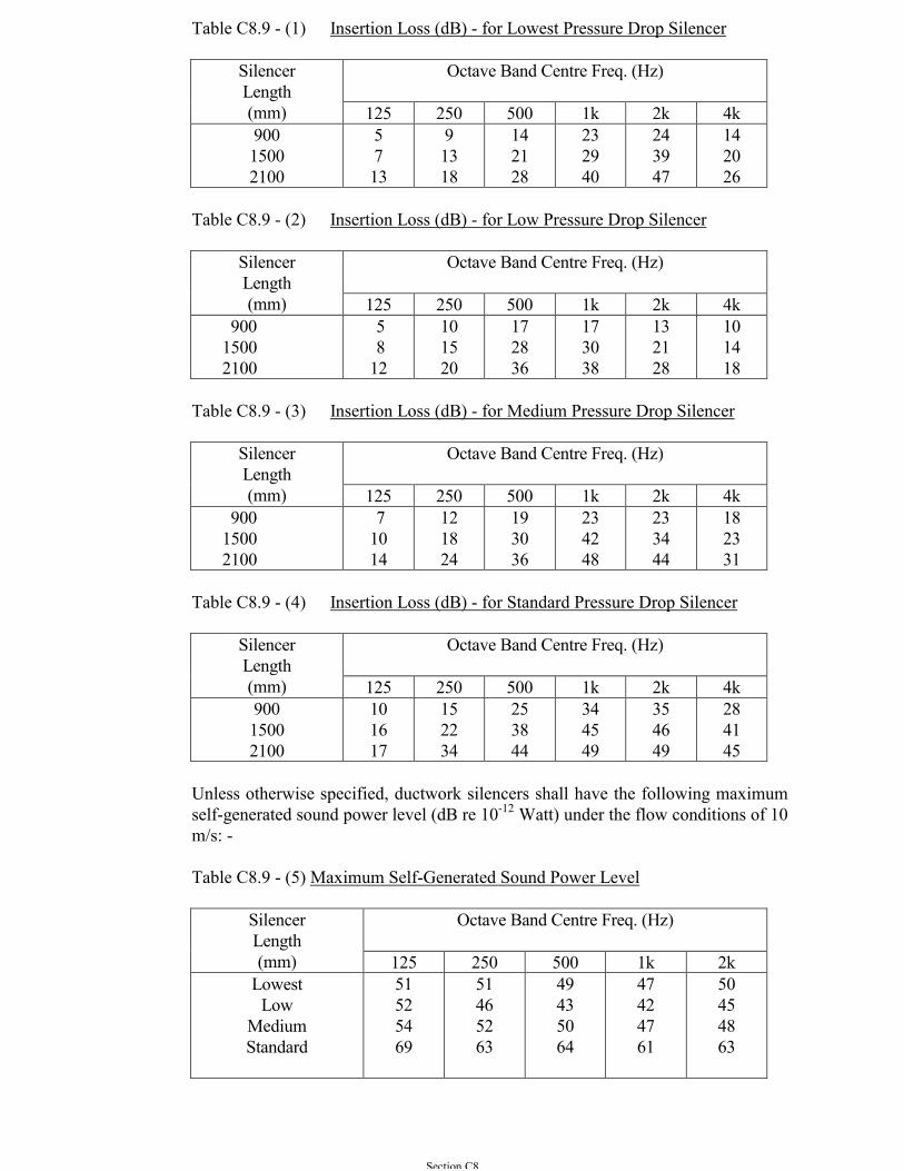
Section C8
Table C8.9 - (1) Insertion Loss (dB) - for Lowest Pressure Drop Silencer
Octave Band Centre Freq. (Hz)SilencerLength(mm) 125 250 500 1k 2k 4k90015002100
5713
91318
142128
232940
243947
142026
Table C8.9 - (2) Insertion Loss (dB) - for Low Pressure Drop Silencer
Octave Band Centre Freq. (Hz)SilencerLength(mm) 125 250 500 1k 2k 4k
90015002100
5 812
101520
172836
173038
132128
101418
Table C8.9 - (3) Insertion Loss (dB) - for Medium Pressure Drop Silencer
Octave Band Centre Freq. (Hz)SilencerLength(mm) 125 250 500 1k 2k 4k
90015002100
71014
121824
193036
234248
233444
182331
Table C8.9 - (4) Insertion Loss (dB) - for Standard Pressure Drop Silencer
Octave Band Centre Freq. (Hz)SilencerLength(mm) 125 250 500 1k 2k 4k90015002100
101617
152234
253844
344549
354649
284145
Unless otherwise specified, ductwork silencers shall have the following maximumself-generated sound power level (dB re 10-12 Watt) under the flow conditions of 10m/s: -
Table C8.9 - (5) Maximum Self-Generated Sound Power Level
Octave Band Centre Freq. (Hz)SilencerLength(mm) 125 250 500 1k 2k
LowestLow
MediumStandard
51525469
51465263
49435064
47424761
50454863
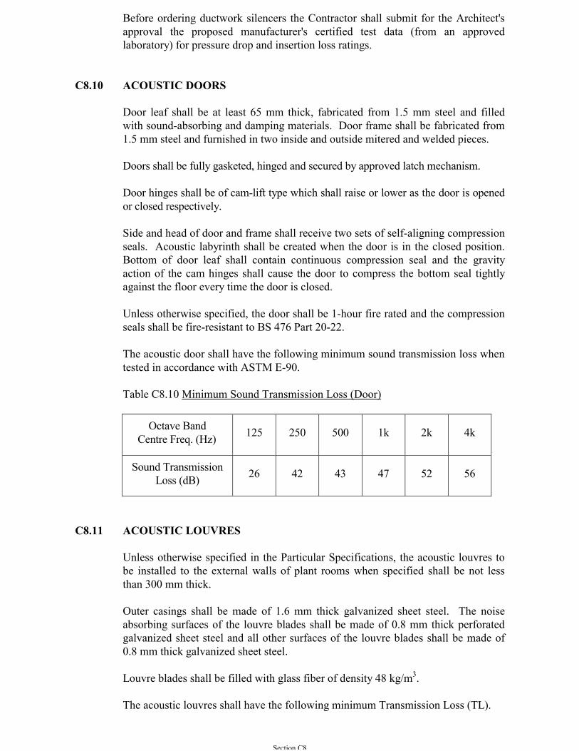
Section C8
Before ordering ductwork silencers the Contractor shall submit for the Architect'sapproval the proposed manufacturer's certified test data (from an approvedlaboratory) for pressure drop and insertion loss ratings.
C8.10 ACOUSTIC DOORS
Door leaf shall be at least 65 mm thick, fabricated from 1.5 mm steel and filledwith sound-absorbing and damping materials. Door frame shall be fabricated from1.5 mm steel and furnished in two inside and outside mitered and welded pieces.
Doors shall be fully gasketed, hinged and secured by approved latch mechanism.
Door hinges shall be of cam-lift type which shall raise or lower as the door is openedor closed respectively.
Side and head of door and frame shall receive two sets of self-aligning compressionseals. Acoustic labyrinth shall be created when the door is in the closed position.Bottom of door leaf shall contain continuous compression seal and the gravityaction of the cam hinges shall cause the door to compress the bottom seal tightlyagainst the floor every time the door is closed.
Unless otherwise specified, the door shall be 1-hour fire rated and the compressionseals shall be fire-resistant to BS 476 Part 20-22.
The acoustic door shall have the following minimum sound transmission loss whentested in accordance with ASTM E-90.
Table C8.10 Minimum Sound Transmission Loss (Door)
Octave BandCentre Freq. (Hz) 125 250 500 1k 2k 4k
Sound TransmissionLoss (dB) 26 42 43 47 52 56
C8.11 ACOUSTIC LOUVRES
Unless otherwise specified in the Particular Specifications, the acoustic louvres tobe installed to the external walls of plant rooms when specified shall be not lessthan 300 mm thick.
Outer casings shall be made of 1.6 mm thick galvanized sheet steel. The noiseabsorbing surfaces of the louvre blades shall be made of 0.8 mm thick perforatedgalvanized sheet steel and all other surfaces of the louvre blades shall be made of0.8 mm thick galvanized sheet steel.
Louvre blades shall be filled with glass fiber of density 48 kg/m3.
The acoustic louvres shall have the following minimum Transmission Loss (TL).
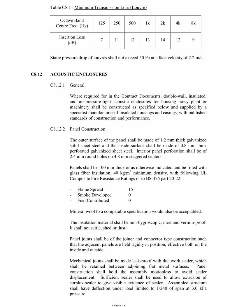
Section C8
Table C8.11 Minimum Transmission Loss (Louvre)
Octave BandCentre Freq. (Hz) 125 250 500 1k 2k 4k 8k
Insertion Loss(dB) 7 11 12 13 14 12 9
Static pressure drop of louvres shall not exceed 50 Pa at a face velocity of 2.2 m/s.
C8.12 ACOUSTIC ENCLOSURES
C8.12.1 General
Where required for in the Contract Documents, double-wall, insulated,and air-pressure-tight acoustic enclosures for housing noisy plant ormachinery shall be constructed as specified below and supplied by aspecialist manufacturer of insulated housings and casings, with publishedstandards of construction and performance.
C8.12.2 Panel Construction
The outer surface of the panel shall be made of 1.2 mm thick galvanizedsolid sheet steel and the inside surface shall be made of 0.8 mm thickperforated galvanized sheet steel. Interior panel perforation shall be of2.4 mm round holes on 4.8 mm staggered centers.
Panels shall be 100 mm thick or as otherwise indicated and be filled withglass fiber insulation, 40 kg/m3 minimum density, with following ULComposite Fire Resistance Ratings or to BS 476 part 20-22: -
- Flame Spread 15- Smoke Developed 0- Fuel Contributed 0
Mineral wool to a comparable specification would also be acceptabled.
The insulation material shall be non-hygroscopic, inert and vermin-proof.It shall not settle, shed or dust.
Panel joints shall be of the joiner and connector type construction suchthat the adjacent panels are held rigidly in position, effective both on theinside and outside.
Mechanical joints shall be made leak-proof with ductwork sealer, whichshall be retained between adjoining flat metal surfaces. Panelconstruction shall hold the assembly motionless to avoid sealerdisplacement. Sufficient sealer shall be used to allow extrusion ofsurplus sealer to give visible evidence of sealer. Assembled structureshall have deflection under load limited to 1/240 of span at 3.0 kPapressure.
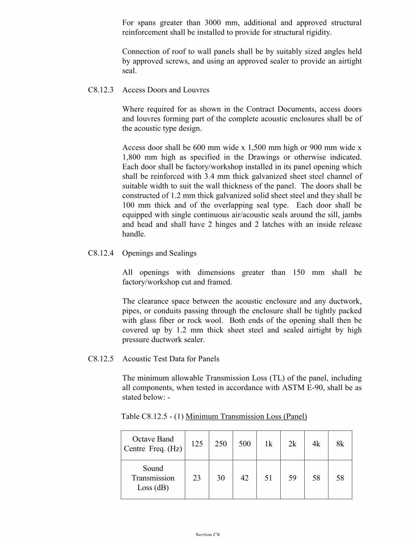
Section C8
For spans greater than 3000 mm, additional and approved structuralreinforcement shall be installed to provide for structural rigidity.
Connection of roof to wall panels shall be by suitably sized angles heldby approved screws, and using an approved sealer to provide an airtightseal.
C8.12.3 Access Doors and Louvres
Where required for as shown in the Contract Documents, access doorsand louvres forming part of the complete acoustic enclosures shall be ofthe acoustic type design.
Access door shall be 600 mm wide x 1,500 mm high or 900 mm wide x1,800 mm high as specified in the Drawings or otherwise indicated.Each door shall be factory/workshop installed in its panel opening whichshall be reinforced with 3.4 mm thick galvanized sheet steel channel ofsuitable width to suit the wall thickness of the panel. The doors shall beconstructed of 1.2 mm thick galvanized solid sheet steel and they shall be100 mm thick and of the overlapping seal type. Each door shall beequipped with single continuous air/acoustic seals around the sill, jambsand head and shall have 2 hinges and 2 latches with an inside releasehandle.
C8.12.4 Openings and Sealings
All openings with dimensions greater than 150 mm shall befactory/workshop cut and framed.
The clearance space between the acoustic enclosure and any ductwork,pipes, or conduits passing through the enclosure shall be tightly packedwith glass fiber or rock wool. Both ends of the opening shall then becovered up by 1.2 mm thick sheet steel and sealed airtight by highpressure ductwork sealer.
C8.12.5 Acoustic Test Data for Panels
The minimum allowable Transmission Loss (TL) of the panel, includingall components, when tested in accordance with ASTM E-90, shall be asstated below: -
Table C8.12.5 - (1) Minimum Transmission Loss (Panel)
Octave BandCentre Freq. (Hz) 125 250 500 1k 2k 4k 8k
SoundTransmission
Loss (dB)23 30 42 51 59 58 58
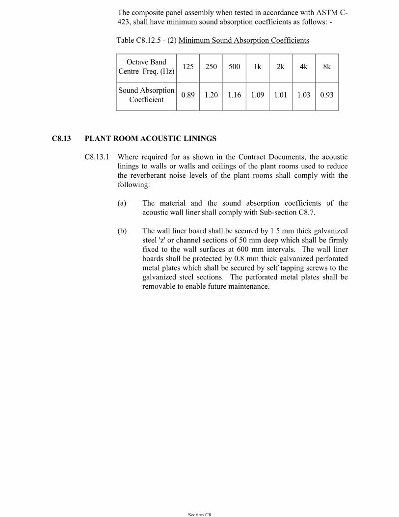
Section C8
The composite panel assembly when tested in accordance with ASTM C-423, shall have minimum sound absorption coefficients as follows: -
Table C8.12.5 - (2) Minimum Sound Absorption Coefficients
Octave BandCentre Freq. (Hz) 125 250 500 1k 2k 4k 8k
Sound AbsorptionCoefficient 0.89 1.20 1.16 1.09 1.01 1.03 0.93
C8.13 PLANT ROOM ACOUSTIC LININGS
C8.13.1 Where required for as shown in the Contract Documents, the acousticlinings to walls or walls and ceilings of the plant rooms used to reducethe reverberant noise levels of the plant rooms shall comply with thefollowing:
(a) The material and the sound absorption coefficients of theacoustic wall liner shall comply with Sub-section C8.7.
(b) The wall liner board shall be secured by 1.5 mm thick galvanizedsteel 'z' or channel sections of 50 mm deep which shall be firmlyfixed to the wall surfaces at 600 mm intervals. The wall linerboards shall be protected by 0.8 mm thick galvanized perforatedmetal plates which shall be secured by self tapping screws to thegalvanized steel sections. The perforated metal plates shall beremovable to enable future maintenance.
Section C9
SECTION C9
PIPE MATERIAL, VALVES, COCKS AND STRAINERS
C9.1 AUTOMATIC AIR VENTS
Automatic air vents shall be used where indicated. They shall have gunmetal orbrass bodies, non-ferrous or stainless steel floats and guides, non-corrodible valvesand seats. Each automatic air vent shall be controlled by a lock-shield valve. Airrelease pipes shall be run to discharge at the nearest suitable and visible point andagreed by the Architect.
C9.2 BALL FLOAT VALVES
Ball float valves shall be of the sizes indicated and shall suit the fill and expansioncisterns or tanks specified. Ball float valves for use with feed and expansioncisterns shall be of the long arm type arranged to shut off when the cistern contains150 mm depth of water. Floats shall be of the vacated plastic or solid polystyreneconstruction and provided with a non-ferrous threaded in built connector.
C9.3 BUTTERFLY VALVES
C9.3.1 Butterfly valves shall be installed where indicated. These shall haveresilient seats which are (in-the-field) replaceable with moulded-in 0-rings to serve as a flange gasket. For sizes of 50 mm dia. to 150 mm dia.inclusive, a notched plate handle shall be provided for the control of thevalve and indication of disk position. For sizes of 200 mm dia. andabove, gear actuator shall be used. All butterfly valves shall be capableof bubble tight shut off. Butterfly valves shall comply with therecognised international standards.
C9.3.2 Grooved ends butterfly valves may also be accepted. The valves shall bein accordance with the following: -
(a) Grooved ends butterfly valves shall be bubble tight closing toISO 5208 standard, enabling quick assembly with mechanicalgrooved coupling on ISO standard pipes.
(b) The manufacturer shall provide independent laboratory tests suchas Underwriters Laboratory or Factory Mutual Research forpressure rating. All testing records and data shall be submitted tothe Architect for approval.
(c) Bodies shall be made of ductile iron grade 400-18, completelycoated with polyamide or products having equivalent functionsor performance against corrosion, suitable for the temperaturerange of 0ºC to 50ºC. The valve shall provide dead end service atmaximum rating.
Section C9
(d) The discs shall be made of ductile iron or brass ASTM B124,with EPDM coating for fresh water application.
(e) The shafts stems shall be made of ANSI 420 stainless steel.
(f) The control handles and the gear operators shall be suitable forlocking in any position. The micro switches shall be built in theactuators and factory adjusted at full open and full closure.Manufacturer shall provide certificate of factory adjustment.
(g) Valve electric operators shall be mounted on valves and tested atfactory.
(h) The valves shall have marking tag in accordance with ISO 5209standard.
C9.4 CHECK VALVES
The body of the check valves shall be made of cast iron to BS EN1561 and ISO185 while the flaps/discs shall be made of Bronze to ISO 197-4 or ductile cast iron.The discs of swing check valves shall be of light construction and pivot on aspindle secured by two phosphor-bronzed hangers. Each valve shall be fitted witha stop to prevent undue movement of the flap and shall be as silent as possible inoperation.
The discs of lift check valves shall be provided with means of guiding the discs andpreventing components from becoming detached in service.
Recoil check valves with size 100 mm and above should have removable cover ontop of the outlet body casing to facilitate inspection of bearings and movementdoor.
C9.5 PIPEWORK APPLICATIONS
Except as may otherwise be specified in Particular Specification, the application ofpipework types to the various systems shall be as stated in Table C9.5. All pipesand fittings shall comply with the relevant Standard and shall have suitablemarkings to indicate the Standard. All ferrous pipework shall comply with ISO5730 and ISO R831.
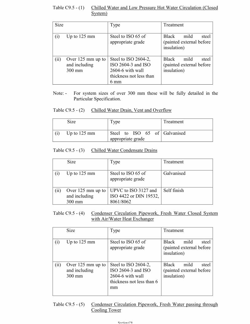
Section C9
Table C9.5 - (1) Chilled Water and Low Pressure Hot Water Circulation (ClosedSystem)
Size Type Treatment
(i) Up to 125 mm Steel to ISO 65 ofappropriate grade
Black mild steel(painted external beforeinsulation)
(ii) Over 125 mm up toand including300 mm
Steel to ISO 2604-2,ISO 2604-3 and ISO2604-6 with wallthickness not less than6 mm
Black mild steel(painted external beforeinsulation)
Note: - For system sizes of over 300 mm these will be fully detailed in theParticular Specification.
Table C9.5 - (2) Chilled Water Drain, Vent and Overflow
Size Type Treatment
(i) Up to 125 mm Steel to ISO 65 ofappropriate grade
Galvanised
Table C9.5 - (3) Chilled Water Condensate Drains
Size Type Treatment
(i) Up to 125 mm Steel to ISO 65 ofappropriate grade
Galvanised
(ii) Over 125 mm up toand including300 mm
UPVC to ISO 3127 andISO 4422 or DIN 19532,8061/8062
Self finish
Table C9.5 - (4) Condenser Circulation Pipework, Fresh Water Closed Systemwith Air/Water Heat Exchanger
Size Type Treatment
(i) Up to 125 mm Steel to ISO 65 ofappropriate grade
Black mild steel(painted external beforeinsulation)
(ii) Over 125 mm up toand including300 mm
Steel to ISO 2604-2,ISO 2604-3 and ISO2604-6 with wallthickness not less than 6mm
Black mild steel(painted external beforeinsulation)
Table C9.5 - (5) Condenser Circulation Pipework, Fresh Water passing throughCooling Tower
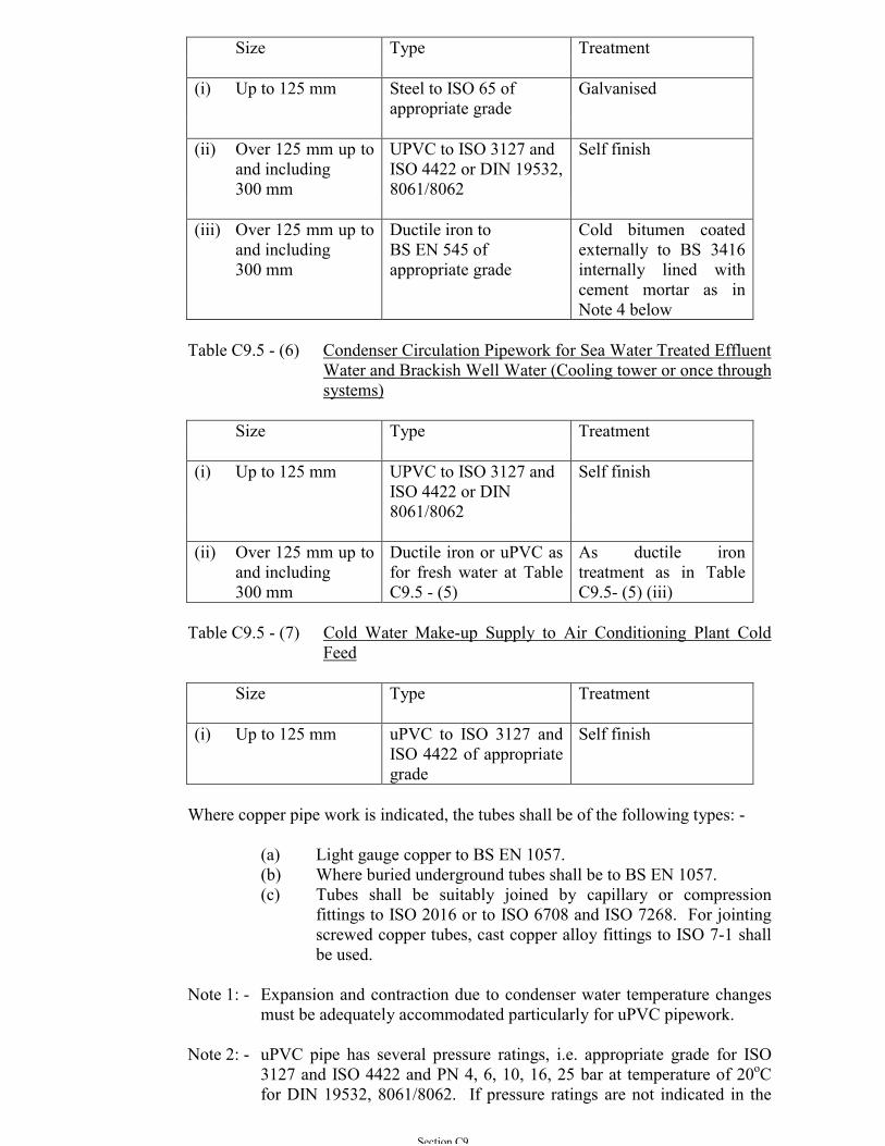
Section C9
Size Type Treatment
(i) Up to 125 mm Steel to ISO 65 ofappropriate grade
Galvanised
(ii) Over 125 mm up toand including300 mm
UPVC to ISO 3127 andISO 4422 or DIN 19532,8061/8062
Self finish
(iii) Over 125 mm up toand including300 mm
Ductile iron toBS EN 545 ofappropriate grade
Cold bitumen coatedexternally to BS 3416internally lined withcement mortar as inNote 4 below
Table C9.5 - (6) Condenser Circulation Pipework for Sea Water Treated EffluentWater and Brackish Well Water (Cooling tower or once throughsystems)
Size Type Treatment
(i) Up to 125 mm UPVC to ISO 3127 andISO 4422 or DIN8061/8062
Self finish
(ii) Over 125 mm up toand including300 mm
Ductile iron or uPVC asfor fresh water at TableC9.5 - (5)
As ductile irontreatment as in TableC9.5- (5) (iii)
Table C9.5 - (7) Cold Water Make-up Supply to Air Conditioning Plant ColdFeed
Size Type Treatment
(i) Up to 125 mm uPVC to ISO 3127 andISO 4422 of appropriategrade
Self finish
Where copper pipe work is indicated, the tubes shall be of the following types: -
(a) Light gauge copper to BS EN 1057.(b) Where buried underground tubes shall be to BS EN 1057.(c) Tubes shall be suitably joined by capillary or compression
fittings to ISO 2016 or to ISO 6708 and ISO 7268. For jointingscrewed copper tubes, cast copper alloy fittings to ISO 7-1 shallbe used.
Note 1: - Expansion and contraction due to condenser water temperature changesmust be adequately accommodated particularly for uPVC pipework.
Note 2: - uPVC pipe has several pressure ratings, i.e. appropriate grade for ISO3127 and ISO 4422 and PN 4, 6, 10, 16, 25 bar at temperature of 20oCfor DIN 19532, 8061/8062. If pressure ratings are not indicated in the
Section C9
drawing or Particular Specification, Contractor shall provide pipes withpressure ratings equal to twice the actual working pressure to which thepipes are being subjected.
Note 3: - Where uPVC pipe is likely to be exposed to sunlight, it shall be protectedagainst the effects of ultra violet light by a suitable paint work coatingmaterial or other form of protection to be agreed with the Architect.
Note 4: - All pipes and fittings shall be cement mortar lined in accordance with BSEN 545, BS EN 598, BS EN969, Type A - Portland pulverised fuel ashcement (PFAC) in accordance with BS 6588 with a minimum pulverisedfuel ash content of 25%; or Type B - sulphate resisting cement (SRC) inaccordance with BS 4027.
C9.6 PLUG COCKS
Plugs for gland cocks shall be ground in. A loose key of mild steel forged to shapeshall be provided for each gland cock.
Air cocks shall be nickel or chrome plated, of the spoutless pattern and withscrewed taper thread. Two loose keys shall be provided for each installationhaving up to ten air cocks and one loose key shall be provided for every additionalten air cocks.
Three-way cocks shall be of the 'T' ported type, the position of the ports beingclearly grooved on the square end of the plug. A loose key shall be provided foreach three-way cock.
C9.7 PRESSURE REDUCING VALVES
Where indicated pressure reducing valves shall be installed. Unless otherwisespecified they shall be as follows: Valves of up to 50 mm size shall have bronze ormalleable iron bodies and may have taper screwed ends. Valves of 65 mm size andover shall have cast iron bodies with ends flanged. Flanges for bronze and ironvalves shall be to ISO 7005, each according to the maximum working pressure.Valves shall be of the following types, as indicated: -
(a) Valves for reducing pressure to apparatus not designed to withstand themaximum pressure of a high-pressure line shall be of an approvedspring-loaded relay operated type. The valve seats and discs shall be ofnickel-alloy or stainless steel and shall be renewable. Each valve shallbe capable of maintaining a reduced outlet gauge pressure within 3.5 kPaof the set pressure and shall be installed with an excess pressure isolatingprotection valve on the low pressure side.
(b) Where the apparatus on the low-pressure side is capable of withstandingthe maximum pressure of the high-pressure line, valves shall be of thesingle-seated spring-loaded diaphragm type. They shall be adjustablewithin the specified low-pressure range and shall be installed with asafety or relief valve on the low pressure side.
Section C9
Each reducing valve shall be installed with an isolating valve and strainer on thehigh-pressure side, excess pressure isolating valve or relief valve on the lowpressure side, pressure gauge with mild steel siphon and bronze cock followed bydown-stream side isolating valve.
Unions shall be provided on the pressure reducing valve side of both isolationvalves in order to facilitate removal of the pressure reducing valve set for servicingor replacement. Where indicated, a bypass valve shall also be installed.
C9.8 STRAINERS
Strainers shall be of the single or the double type as indicated with connectionsscrewed thread for bores of up to and including 50 mm and flanged for bores of 65mm and over.
Strainers of up to 50 mm shall be of gunmetal or bronze. The bodies of singlestrainers of 65 mm bore and above and all double strainers shall be of cast iron.
Straining cages and their supporting structure shall be of non-ferrous metal orstainless steel with 1.5 mm diameter perforations or finer if indicated. Cage shall beat least five times the cross-sectional area of the pipe.
Double strainers shall incorporate a changeover device to enable either strainer tobe selected and to isolate the idle strainer from the fluid flow.
C9.9 SPECIALISED CONTROL VALVES
Motorised control valves, and solenoid valves used for automatic control purposesshall be as specified in Sub-section C5.49 or as indicated in the ParticularSpecification. Mixing valves shall comply with BS 1415 Part 2.
C9.10 VALVE APPLICATIONS
C9.10.1 For fresh and chilled water; gate valves shall be used except whereregulation is required in which case globe valve shall be installed butthey must be positioned so as not to prevent drainage of the piping.
C9.10.2 For fresh water service valve both the gate and globe type shall beconstructed of cast iron body with bolted cast iron bonnet, malleable ironhand wheel, bronze wedge and seat, forged manganese bronze or hightensile bronze spindle, with graphited packing and compressed fibre.
C9.10.3 Sea water services valves installed in the sea water pump house and/orinside the air conditioning plant room shall be constructed of cast ironbody with zinc free bronze trim, bolted cast iron bonnet, malleable ironhand wheel, zinc free bronze stuffing box, gland, thrust, plate, yoke,wedge, seat and yoke sleeve with nickel alloy faces, stainless steelspindle with outside screw of rising stem or inside screw of non risingstem (whichever is specified), gunmetal nuts, and graphited packingcompressed fibre packing.
Section C9
C9.11 VALVES AND COCKS
C9.11.1 Valves, cocks, taps and other accessories shall be of the type andworking pressure suitable for the applied system and shall be supportedby valid documents with approval from the appropriate authority. Theyshall also bear the appropriate ISO Standard with marks. See also Sub-section B9.5 and B9.10.
C9.11.2 Bodies of valves and cocks of up to and including 50 mm size shall be ofcast gunmetal or bronze; approved valves having hot-pressed bodies maybe offered as an alternative.
C9.11.3 Unless otherwise specified, bodies of valves of 65 mm size and largershall be of cast iron. Castings and pressings shall be of good quality,clean and smooth and free from scale or flaws.
C9.11.4 All working parts shall be of gunmetal or chrome nickel alloy. Holes incovers or in gates for screwed portions of spindles shall have full threadsof a length not less than the diameter of the spindle over the threads.Glands shall be machined to provide a naming fit between the spindleand the stuffing box. Stuffing boxes shall be properly packed, or fittedwith 'O' rings which shall be located in plastic bushes.
C9.11.5 Gate valves shall have split or solid wedge gates. Disc valves shall haverenewable discs free to rotate on the spindle.
C9.11.6 Valves and cocks on mild steel pipework of up to and including 50 mmsize shall have taper screwed ends, and of 65 mm size and above shallhave flanged ends.
Valves and cocks on copper pipework shall have connecting generally asfor fittings.
C9.11.7 Wheel valves where exposed to view on appliances such as fan coil unitsand induction units shall have union ends and either: -
(a) Composition hand-wheels shaped to enclose the stem and gland,or,
(b) Easy clean polished lock shields and composition hand-wheels.
Valves not normally exposed to view shall be fitted with cast metal handwheel or lock shields.
C9.11.8 Straight pattern valves shall be of the full-way gate type. Angle valvesshall have domed discs designed to offer minimum resistance to flow.
C9.11.9 Regulating valves on circuits shall have characterised plugs and alockable spindle with an indicator to show the proportional opening.
C9.11.10 Lock-shield valves shall have easy-clean shields or enclosures to matchwith the inlet valves; a minimum of two loose keys shall be provided for
Section C9
each size of valve spindle used on the Contract. Where indicated, thelock-shield valves shall have characterised plugs as for the regulatingvalves.
C9.11.11 Isolating valves, lockable where indicated, shall be of the followingtypes: -
(a) Fullway gate type except for valves with side pressure tapping ofup to 50 mm size which shall be of the oblique type;
(b) Parallel or taper plug type.
C9.11.12 Fullyway gate valves shall have metal wheel handles. Wedge gates andall seating, including the top of the wedge and the associated back seat ofthe bonnet facing, shall be accurately machined, or alternativelydesigned to provide a back seating. Plug valves shall be arranged for 90ºoperation with stops on the valve body to limit movement. Lubricatedplug valves shall incorporate a check device in the plug for the retentionof lubricant applied under pressure. A spare charge of lubricant shall beprovided for each valve.
Section C10
SECTION C10
SYSTEM MONITORING INSTRUMENT
C10.1 GENERAL
The content related to electrical control shall be read in conjunction with SectionsC4, C5 and C7.
The system monitoring instrument in this Section shall also meet with therequirements as stipulated in the latest Guidance Notes for Management of IAQ inOffices & Public Places and the Guide for Participation in the IAQ CertificationScheme published by the HKSAR Government.
Scale ranges shall be appropriate for indicating the extreme values, on and off state,of the plant. The design maximum operating condition shall be indicated at not lessthan 75% of the total scale length.
Where required in the Particular Specification, all signals generated from theinstruments and devices shall be suitable to work in conjunction with a CentralControl and Monitoring System (CCMS).
C10.2 SYSTEM STATIC PRESSURE GAUGES FOR AIR DISTRIBUTIONSYSTEMS
System static pressure gauges shall be of the single limb inclined manometer typewith an accuracy of ± 3%.
C10.3 THERMOMETERS - AIR IMMERSION
Thermometers shall be of the mercury-in-glass type of at least 150 mm long withaccuracy of ± 0.5ºC.
C10.4 THERMOMETERS - LIQUID IMMERSION
Thermometers shall be of the mercury-in-glass type of at least 150 mm long withaccuracy of ± 0.5ºC.
Unless otherwise specified, material of thermometer pocket shall be of stainlesssteel grade 316.
C10.5 PRESSURE GAUGES FOR WATER SYSTEMS
Pressure gauges shall comply with BS EN 837-1 calibrated in kPa from zero to notless than 1.3 times and not more than twice the operating pressure of the respectiveequipment/system and shall be accurate to 1.5% of full scale reading, unlessotherwise specified.
Section C10
The dials of gauges shall not be less than 100 mm diameter and the cases shall beof polished brass or chromium-plated mild steel with optical sight glass.
Pressure gauges used solely to indicate the head and pressure of water shall beprovided with an adjustable red pointer set to indicate the normal working pressureor head of the system.
C10.6 PITOT STATIC TUBE
The flow sensing device shall be of the annubar type in compliance with ISO 3966and ISO 7194, inserted through the wall of the pipe via suitable bush supplied bythe sensing device's manufacturer.
The equipment shall be manufactured by a reputable and proven manufacturer andshall receive the Architect’s approval before installation.
Each pitot static sensor shall be permanently marked externally with the directionof flow.
C10.7 ORIFICE PLATE METERING
Where these are to be installed the orifice plates shall be of stainless steel and of thewell established manufacturer’s make with proven performance characteristics incompliance with ISO 5167-1. The resistance across the plant orifice shall notexceed 5 kPa (0.05 bar).
The plate shall have two valved tappings for connection to manometer or respondermeter, etc., similar to that described in Sub-section C10.6 above.
C10.8 ELECTROMAGNETIC AND ULTRASONIC FLOWMETERS
The flowmeter shall be of the direct reading type, i.e. in l/s, and shall be suitable forthe chemical and physical properties of the fluids to be measured and suitable forboth horizontal and vertical installations.
Each flowmeter shall consist of the flow sensor, an integral signal converter/transmitter and a digital display unit. The flow sensor shall be installed in the waterpipework without obstructing the flow. The protection class of the sensor andconverter/transmitter housing shall be at least to IP 67 and IP 65 respectively. Theflowmeter shall have a constant accuracy to a maximum error of ± 0.5% of theactual flow for flow velocity of greater than or equal to 0.5 m/s. The installation ofthe flowmeter shall be as per the manufacturer’s recommendation with sufficientlength of straight pipe run both at the upstream and downstream piping.
The flowmeter shall conform to BS EN 50081 and BS EN 50082 or similarinternational standards on Electro-magnetic Compatibility (EMC) compliance forindustrial and commercial applications.
Section C10
C10.9 ENERGY METERS
The calculator unit of an energy meter shall calculate and display digitally thewater enthalpy consumption in kWh with an accuracy to a maximum error of ±1.5% throughout the range of measurement. The number of digits of accumulatedenthalpy consumption display shall not be less than six. The housing protection forthe microprocessor and calculator unit shall not be less than IP 54. Therequirement for the temperature sensors and the flowmeter shall be as specifiedelsewhere in this General Specification.
Signal connection facilities to the CCMS shall be provided for displaying theenergy consumption computed and the flow rate and temperature readings.
Section C11
SECTION C11
THERMAL INSULATION
C11.1 GENERAL
C11.1.1 Thermal insulation shall comply with the requirements of BS 5422 andBS 5970 or other statutory standards such as IEC, ISO and etc orequivalent.
C11.1.2 Unless otherwise indicated, all thermal insulating materials used withinany building shall, when tested in accordance with BS 476 or equivalentcomply with the following: -
(a) BS 476 Part 12: Ignitable T;(b) BS 476 Part 6: Fire propagation I < 12, i1 < 6;(c) BS 476 Part 7: Surface spread of Flame Class 1,
or comply with Sub-section C11.1.2 (a) as mentioned above and conformto Class 'O' to UK Building Regulation 1991 certified by the “WarringtonFire Test Laboratory” or approving organizations and standardsrecognised by the Fire Services Department.
C11.1.3 The insulation used for the air conditioning installation is “air” insulationwhich shall satisfy the following:
(a) Adequate strength and rigidity to maintain the thickness of air.
(b) Creating adequate number of closed air shells within the materialto minimize heat loss due to convection and conduction.
(c) Covered on exposed surface with good quality foil to stop heatloss from radiation.
C11.1.4 Insulation materials and their finishes shall be free from asbestos. Whereany work is carried out on existing insulation material or finish whichcontains asbestos in any form the Contractor’s attention is drawn to theresponsibilities under the provisions of the Asbestos Regulations currentin the Hong Kong SAR at the time of the works. The Contractor shallalso notify the Architect should the presence of asbestos be suspected.
C11.1.5 Insulation materials and finishes shall be inherently proved againstrotting, mould and fungal growth and attack by vermin, be non-hygroscopic and in all respects be suitable for continuous use throughoutthe range of operating temperatures and for the environment indicated.
C11.1.6 The Contractor shall bear the cost and provide relevant certificates froman approved testing laboratory in order to prove the physical properties ofthe insulation to be used in the projects are conforming to thespecification.

Section C11
C11.2 TYPES OF THERMAL INSULATION MATERIALS
The type of insulation required for a particular installation will general be indicatedin the Particular Specification. Where this is not so the Contractor shall include forthe types described herein:
C11.2.1 Type 'A' - CFC & HCFC Free Phenolic Foam Insulation
(a) Temperature range : sub zero to 120°C
(b) Density : 40 kg/m3
Except at pipe, ductwork and other support points where a higherdensity load bearing quality insulation shall be used inaccordance with the manufacturers’ recommendations. Ingeneral, phenolic foam sections with 80kg/m3 for pipe sizes of upto 125mm and 120kg/m3 for pipe sizes of 150mm or above andmade to the same thickness as the adjacent pipe insulation.
(c) Compressive strength: 140 kN/m2
(BS 4370 : Part 1, method 3 or ISO 844) :
(d) Thermal conductivity: 0.022 W/m°C at 20°C mean temperature(BS 4370 : Part 2, method 7).
(e) Closed cell content: 90% minimum (BS 4370 : Part 2, method 10or ISO 4590).
(f) Vapour transmission: 10 micron gram meter/Nh at 38°C 88%RH (BS 4370 : Part 2, method 8 or ISO 1663).
(g) Fire rating: shall have class ‘O’ fire rating and test certificatefrom independent laboratory.
The above properties shall be tested independent of facingswhich shall be factory applied Class 'O' double sided reinforcedfoil vapour barrier for both condensation control and mechanicalprotection. The external side shall be of white antiglare coatingand the internal side shall be of aluminium foil fully adhered tothe phenolic foam. Facing with all service jacket on the outside isalso acceptable. The surface emittance of the all service jacketshall be 0.7 or greater when tested with ASTM E-408. Inaddition, the performance of both vapour barriers and all servicejacket shall comply with the requirement stipulated at Sub-section C11.4.2
The manufacturer shall provide evidence if required by theArchitect, that the above properties of the material suppliedremains constant or are stable enough throughout the workinglife.
Section C11
C11.2.2 Type 'B' - Preformed Rigid Glass Fibre Insulation
Where specified the Contractor shall supply and install preformed fibreglass sections of the appropriate size to fit hot water pipework only andcapable of accommodating the temperature range for the system withoutstructural failure of the fibres or the bonding agency.
Preformed fibre glass sections shall have a density of not less than 64kg/m3 and a minimum length of 0.9 m. Butt joint tape not less than 100mm shall be used to ensure perfect sealing of the joints between sections.
The thermal conductivity (k value) of the fibreglass shall not be morethan 0.033 W/m°C at a mean temperature of 20°C. The fiber diameter ofthe fibreglass shall be of 4 to 10 micron and fibre length 3 to 6 cm.
All fibreglass insulation shall be completely sealed at all joints. Allholes, tears, punctures, etc. made in the vapour barrier shall becompletely sealed with the same specified foil tape.
C11.2.3 Type ‘C’ - Flexible (Semi Rigid) Glass Fibre Blanket Type Insulation
This form of insulation shall not be used on pipework.
Insulation used for ductwork shall be semi rigid having a density of notless than 32 kg/m3 and thickness not less than 38 mm. The fiberdiameter of the fibreglass shall be of 4 to 10 micron and fibre length shallbe of 3 to 6cm.
The thermal conductivity (k value) of the fibreglass shall not be morethan 0.036 W/m°C at a mean temperature of 20°C. The thermalresistance (R value) shall be more than 1.08 m2°C/W.
C11.2.4 Type 'D' - Flexible Closed Cell Elastomeric Insulation.
Flexible closed Cell Elastomeric Insulation shall be CFC free, incontinuous lengths, with factory applied talc coating on inner surface.Flexible Closed Cell Elastomeric Insulation shall comply with thefollowing requirements:
(a) Thermal conductivity(at 20oC mean temperature)
: <0.04 W/moC
(b) Density : 65 kg/m3 ± 5%
(c) Water vapour permeability(without additional vapour barrier foil)
: 0.28 microngram meter/Nh
(d) Maximum operating temperature : > 80oC
Section C11
(e) No putrefaction and mildew shall form on the insulationmaterial. The water absorption properties of the insulationshall be of not more than 1.5% after 28 days.
(f) The material, including adhesives and all accessories shallhave fire properties to Class 'O' comply with therequirements of the latest edition of Building Regulationin UK. The insulation material shall be a 'built-in' vapourbarrier and achieve condensation control without anyadditional vapour barrier foil.
(g) Smoke Visibility (ISO 5659-2)The mean specific optical density, Dm shall be less than500 under all test conditions. The thickness of the testspecimen shall be 25mm and the Dm shall be themaximum value of the specific optical density (Ds10) ofthe three tests computed at 10 minutes time interval.
(h) Smoke ToxicityThe results shall comply and in accordance with either ofthe following standards or equivalent :
- International Maritime Organisation (IMO) –International Code for Application of Fire TestProcedure : Part 2 – Smoke and Toxicity Test,IMO MSC 61(67)
- Naval Engineering Specification (NES) 713 (Issue3) – Determination of the Toxicity Index of theProducts of Combustion from Small Specimens ofMaterial
C11.2.5 Type 'E' - Polystyrene Insulation
Only where specified or approved preformed or slab polystyrene may beused.
Polystyrene insulation shall be of the required thickness to meet with thethermal insulation values stated in Sub-section C11.5 - Tables 'X' and 'Y'or as stated in the Particular Specification.
The material shall be of the type which is defined as ‘non-selfcombustible’. In all cases in order to meet with the requirements of Sub-section C11.3.
C11.2.6 Type 'F' - Hydrous Calcium Silicate (HCS) and Rock Wool PipeInsulation.
This material is more appropriate to the insulation of hot pipework andother hot metallic surfaces.
Where specified or approved this material shall be provided in thepreformed sections having a top density of 200 kg/m3 of chemically-
Section C11
reacted calcium silicate combined with mineral fiber, with factoryapplied jacket.
C11.2.7 Type 'G' - Magnesia Insulation
Where specified or approved this material is appropriate to the insulationof hot pipework and other hot surface. It shall consist of 85% magnesiawith 15% cement bonding agent applied wet to the hot surfaces allowedto dry out and when the appropriate thickness has been achievedsmoothed off, covered with galvanised iron wire netting of 25 mm meshand then further covered with 15 mm of cement plaster trowelled smoothand when dry painted to an approved colour as Sub-section B11.8.
C11.2.8 Type ‘H’ – Free CFC, HCFC and HCF Polyurethane Foam Insulation
(a) Temperature range : Sub zero to 80oC(b) Density : 48kg/m3
(c) Compressive strength : 245kN/m2 (BS 4370 : Part 1, method 3 orISO 844)
(d) Thermal Conductivity 0.024W/moC at 20oC mean temperature(e) Close cell content – 95% minimum (BS 4370 : Part 2, method 10
or ISO 4590)
The insulation panel shall be laminated at factory with a minimum of 60-micron thick aluminium foils on both sides. The aluminium foil shall beembossed and coupled with a 2g/m2 layer of polyester paint. Thealuminium foil shall comply with the following requirement:
(a) Aluminium with pureness 98.8% (Aluminium Alloy 8079)(b) Thickness : 60µm(c) Tensile strength (DIN 50154) : > 60N/m2(d) Elongation (DIN 50154) : > 8%
The insulation panel together with the above-specified aluminium foilsshall achieve condensation control without any additional vapour barrierfoil as stated in Sub-section C11.4.
C11.3 MEASURE TO PREVENT SMOKE NOXIOUS & TOXIC FUMEPROPAGATION IN EVENT OF FIRE
When requested by the Architect, evidence of fire classification, obtained from anapproved testing laboratory, shall be provided by the Contractor in order to certifythat materials comply with Sub-section C11.1.
In exceptional circumstances, where insulation materials have been permittedwhich do not strictly meet with the fire properties stated in Sub-section C11.1, thematerials shall only be provided on the condition that: -
(a) The sections are secured to the pipework or ductwork with non-flammable or toxic smoke producing adhesives.
Section C11
(b) They are wrapped in 25 mm mesh, 1mm thick galvanised wire nettingand covered in self setting cement of not less than 15mm thick trowelledsmooth and if required (because they are exposed) painted in accordancewith Section A8.
Such insulation shall similarly be sealed above the ductwork fitted tightand adjacent to the ceilings and beams or at the points near otherobstructions.
Where total sealing by galvanised iron wire netting and 15 mm of cementplaster cannot be achieved then such forms of insulation will not bepermitted.
Permission to use insulation materials that must be sealed with cementplaster in order to avoid generation of toxic fumes and smoke in theevent of a fire will only be given in those circumstances where suchapplication is considered safe by the Architect.
C11.4 VAPOUR BARRIERS
C11.4.1 Where thermal insulation is applied to the outside of piped and ductworkservices, equipment and plant used to convey, store or generate fluids orgases at temperatures lower than the design ambient dew pointtemperature indicated, a water vapour barrier shall be provided unless thetender specification states otherwise. The vapour barrier where employedshall be applied such that it is continuous and gives protection to thewhole surface of the insulation which it protects.
It shall not be pierced or otherwise damaged by supports or by theapplication of external cladding.
The insulation on continuous pipe and ductwork shall be sectionalised byvapour barriers to be applied at a maximum of 5 m intervals to isolatecondensation problems caused by perforation of external barrier to theaffected section.
C11.4.2 Aluminium foil vapour barriers used for insulation of all pipes andductwork shall conform to the following requirements:
(a) Machine Direction Tensile Strength (ASTM D828) ≥ 12kN/m(b) Cross Direction Tensile Strength (ASTM D828) ≥ 9kN/m(c) Bursting Force (AS2001.2.19 : 1988) ≥ 120N or Bursting
Strength ≥ 6 kg/cm2 in accordance with ASTM D774(d) Water Vapour Permeance (ASTM E96) ≤ 1.0ηg/Ns(e) Surface emittance of external surface (ASTM E408) ≥ 0.7
C11.4.3 All joints shall be either factory or on job site fabricated. All joints shallallow for 50 mm overlap of vapour barrier and the joints shall becompletely sealed using foil tape with a minimum width of 100 mmconforming to the following specifications:
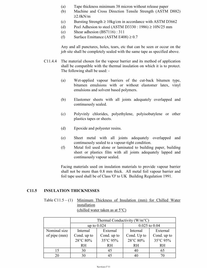
Section C11
(a) Tape thickness minimum 38 micron without release paper(b) Machine and Cross Direction Tensile Strength (ASTM D882)
≥2.0kN/m(c) Bursting Strength ≥ 10kg/cm in accordance with ASTM D3662(d) Peel Adhesion to steel (ASTM D3330 : 1986) ≥ 10N/25 mm(e) Shear adhesion (BS7116) : 311(f) Surface Emittance (ASTM E408) ≥ 0.7
Any and all punctures, holes, tears, etc that can be seen or occur on thejob site shall be completely sealed with the same tape as specified above.
C11.4.4 The material chosen for the vapour barrier and its method of applicationshall be compatible with the thermal insulation on which it is to protect.The following shall be used: -
(a) Wet-applied vapour barriers of the cut-back bitumen type,bitumen emulsions with or without elastomer latex, vinylemulsions and solvent based polymers.
(b) Elastomer sheets with all joints adequately overlapped andcontinuously sealed.
(c) Polyvinly chlorides, polyethylene, polyisobutylene or otherplastics tapes or sheets.
(d) Epoxide and polyester resins.
(e) Sheet metal with all joints adequately overlapped andcontinuously sealed to a vapour-tight condition.
(f) Metal foil used alone or laminated to building paper, buildingsheet or plastics film with all joints adequately lapped andcontinuously vapour sealed.
Facing materials used on insulation materials to provide vapour barriershall not be more than 0.8 mm thick. All metal foil vapour barrier andfoil tape used shall be of Class 'O' to UK Building Regulation 1991.
C11.5 INSULATION THICKNESSES
Table C11.5 – (1) Minimum Thickness of Insulation (mm) for Chilled Waterinstallation(chilled water taken as at 5°C)
Thermal Conductivity (W/m°C)up to 0.024 0.025 to 0.04
Nominal sizeof pipe (mm)
InternalCond. up to28°C 80%
RH
ExternalCond. up to35°C 95%
RH
InternalCond. Up to28°C 80%
RH
ExternalCond. up to35°C 95%
RH15 30 45 40 6520 30 45 40 70
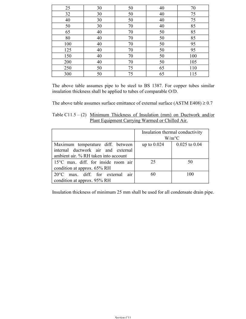
Section C11
25 30 50 40 7032 30 50 40 7540 30 50 40 7550 30 70 40 8565 40 70 50 8580 40 70 50 85100 40 70 50 95125 40 70 50 95150 40 70 50 100200 40 70 50 105250 50 75 65 110300 50 75 65 115
The above table assumes pipe to be steel to BS 1387. For copper tubes similarinsulation thickness shall be applied to tubes of comparable O/D.
The above table assumes surface emittance of external surface (ASTM E408) ≥ 0.7
Table C11.5 – (2) Minimum Thickness of Insulation (mm) on Ductwork and/orPlant Equipment Carrying Warmed or Chilled Air.
Insulation thermal conductivityW/m°C
Maximum temperature diff. betweeninternal ductwork air and externalambient air. % RH taken into account
up to 0.024 0.025 to 0.04
15°C max. diff. for inside room aircondition at approx. 65% RH
25 50
20°C max. diff. for external aircondition at approx. 95% RH
60 100
Insulation thickness of minimum 25 mm shall be used for all condensate drain pipe.
Section C12
SECTION C12
UNITARY AIR-CONDITIONER
C12.1 GENERAL
Unitary air-conditioners shall include:-
(a) Single package unit,(b) Packaged unit and remote condenser,(c) Condensing unit and blower coils,(d) Condensing unit with variable refrigerant volume control and indoor fan
coil units,(e) Multi-split system and(f) Water-cooled package and water pump package
Unitary air-conditioners shall be factory fabricated and assembled. The equipmentshall be rated and tested in the same country of manufacture and meet with therequirements of the American Air-conditioning and Refrigeration (ARI) Standards210 or other international recognized quality assurance standards approved by theArchitect.
The most energy efficient model in the series shall be selected for submission andshall be referred to Sub-section C12.20 of this General Specification.
C12.2 EQUIPMENT SUITABLE FOR LOCAL ELECTRICITY SUPPLY
Unless otherwise specified, electrical equipment of the unitary air-conditionersshall be suitable for use with 3-phase and neutral, 4-wire, 380/220 V ±6%, 50Hz.±2% source neutral earthed system with provision of bonding.
Transformer may be used for equipment designed for operation on voltages otherthose specified above. Whenever possible, these shall be installed within the unit.
C12.3 DE-RATING FACTOR APPLIED TO 60 HERTZ EQUIPMENT
In the absence of published manufacturer’s rating for 50 Hertz operation, a factor of0.83 is to be applied to the capacity rating of unitary air-conditioners manufacturersfor 60 Hertz operation subject to the approval by the Architect.
C12.4 SELECTION OF AIR-COOLED CONDENSERS AND CONDENSINGUNITS
Air-cooled condensers and condensing units of unitary air-conditioners shall beselected to give rated capacity with condensing temperature not exceeding 50°C forthe ambient condition as specified under Sub-section A3.1.10 of this GeneralSpecification.
Section C12
C12.5 CASING
Casings of unitary air-conditioners shall be constructed of rigid galvanised sheetsteel and painted in accordance with Section A8, suitably reinforced with channelsand sections to form a robust cabinet. Casing for outdoor installation shall be ofweatherproof finish, preferably galvanised, painted or anodized aluminum.
C12.6 COMPRESSOR
Compressors shall be rotary, scroll or reciprocating of either the hermetically sealedtype or the semi hermetically sealed type. Compressor shall be complete withinternal motor protection, positive lubrication, mufflers, crankcase heater, andinternal and external vibration isolation.
C12.7 SUPPLY AIR FAN AND MOTOR
Supply air fans shall be of the double width, double inlet, centrifugal type of amplesized for operation against the specified static pressure. Fan motors shall bepermanently lubricated and have adequate power so as to be non-overloadingthroughout the range of the fan characteristic. The motor shall be high efficiencymotor.
C12.8 COOLING AND HEATING COILS
Cooling coils shall be of the direct expansion type and constructed with coppertubes and aluminum fins to give high heat transfer performance. The coils shallhave sufficient number of rows of tubes to provide efficient dehumidification of theair in addition to its cooling.
Heating coil shall be constructed with copper tubes and aluminum fins to give highheat transfer performance.
C12.9 AIR FILTER
Air filters shall unless otherwise specified be of the washable panel type and of anaverage weight arrestence efficiency not less than 85% according to ASHARE 52-76. Higher filter efficiency shall be adopted to meet with the IAQ objectivedesigned and the requirement shall be referred to Section C1.
C12.10 AIR COOLED CONDENSERS
Air-cooled condensers shall unless otherwise specified be suitable for outdoorinstallation with ample capacity to dispose of the rejected heat from the airconditioning system. Condenser coils shall be constructed with copper tube andaluminum fins. Special corrosion resistant treatment for the condenser coils andfins shall be considered for the equipment to be located on corrosive environment.
Section C12
C12.11 ELECTRIC DUCTWORK HEATER
Electric ductwork heaters shall be provided for winter heating or re-heating anddesigned in accordance with Section C3.
C12.12 REFRIGERANT PIPING
External refrigerant piping when required shall include all necessary valves, fittingand insulation. All insulation shall be properly protected with mechanical meanssuch as metallic cladding or cement plastering and painting. Size of the refrigerantpipe and fittings shall be in accordance with the recommended standards as statedin Sections B6 and C6.
C12.13 CONDENSATE DRAIN PIPE
Condensate drain pipe shall be adequate insulated and mechanical protected inaccordance with Sections B11 and C11 of this General Specification.
C12.14 SAFETY CONTROL
Controls shall be factory wired. Field wiring in conduit or trunking shall be limitedto interconnections between separate pieces of equipment and power wiring. Eachunit shall be protected and controlled by a factory built control panel incorporatingall necessary devices, switches, indicator, etc. Functions required shall includethose such as interlock with lubricating oil pump and other auxiliary componentsfor unit starting, control circuit for compressor stop with pump down and crankcaseheaters, automatic unloading, isolating switches and emergency stop facilities.
Safety protections shall include low lubricating oil pressure cutout, low evaporatingpressure cutout, high condensing pressure cutout, low refrigerant temperaturecutout, high motor coil temperature cutout, and other protections necessary for theproper and safe operation of the unit. Overload and motor burnout protections shallbe provided as well.
C12.15 OPERATIONAL CONTROL
For a conventional split type A/C unit, a wired or wireless remote controller shallbe provided for the selection of room temperature setting, fan speed and timersetting. For an advance multi-zone modular split type, the remote controller shall beof the liquid crystal display (LCD) type with an on-off switch for operationalfeatures such as speed selection, timer setting, temperature setting, self-diagnosisfunction and auto restart function.
C12.16 SINGLE PACKAGED AIR-CONDITIONER
Single package unit shall be of the completely self-contained type with factorywired controls and factory assembled components and piping. The unit shall
Section C12
include one/two rotary, scroll or reciprocating compressors of either thehermetically sealed or semi-hermetically sealed type, condenser coil, condenser fanand motor, direct expansion cooling coil, blower, air filters, drier of the renewablecartridge type complete with isolating valve, expansion valve, controls and safetydevices all housed in a weather-proof and metal casing of robust yet attractiveappearance.
C12.17 PACKAGED AIR-CONDITIONER WITH REMOTE CONDENSER
The unit shall contain all components factory assembled, (as the single packagedunit with the exception of the condenser), in a sturdy painted G.I. metal casingarranged for vertical or horizontal mounting inside the building.
C12.18 SPLIT CONDENSING UNIT AND AHU
The condensing unit shall include rotary, scroll or reciprocating compressors, air-cooled condensing coils, fans and motors control and safety devices, piping and allnecessary accessories factory assembled in a weatherproof painted G.I. casing. Therefrigerant circuit shall be field connected to the matched AHU or fan coil unitseach complete with direct expansion cooling coil, expansion valve, blower withmotor and the necessary number of air filters in a well insulated, sturdy G.I. metalcasing with paint to an attractive appearance.
C12.19 VARIABLE REFRIGERANT VOLUME SYSTEM
The air conditioning system shall be of the multi-zone modular split type. Eachzone shall consist of one air-cooled outdoor condensing unit connected to a groupof indoor fan coil units in one single refrigerant circuit. The outdoor unit shall notcomprise more than three compressors. For multi compressors outdoor unit, oneshall be inverter control compressor. The inverter compressor shall be incorporatedwith a frequency inverter control to achieve the optimum flow of refrigerant inresponse to the actual load.
The multi-zone modular split type unit shall be provided with heating (HeatRecovery) and cooling output simultaneously.
C12.20 ENERGY EFFICIENCY PERFORMANCE
All unitary air conditioners shall be selected aiming for the highest operationefficiency. The minimum Coefficient of Performance for Air-Cooled Unitary AirConditioner excluding room cooler shall be as shown in the Table below:-
Table C12.20
Capacity Range(kW)
Above 10 and below 40 41 to 200 Above 200
MinimumCoefficient ofPerformance
2.2 2.2 2.4
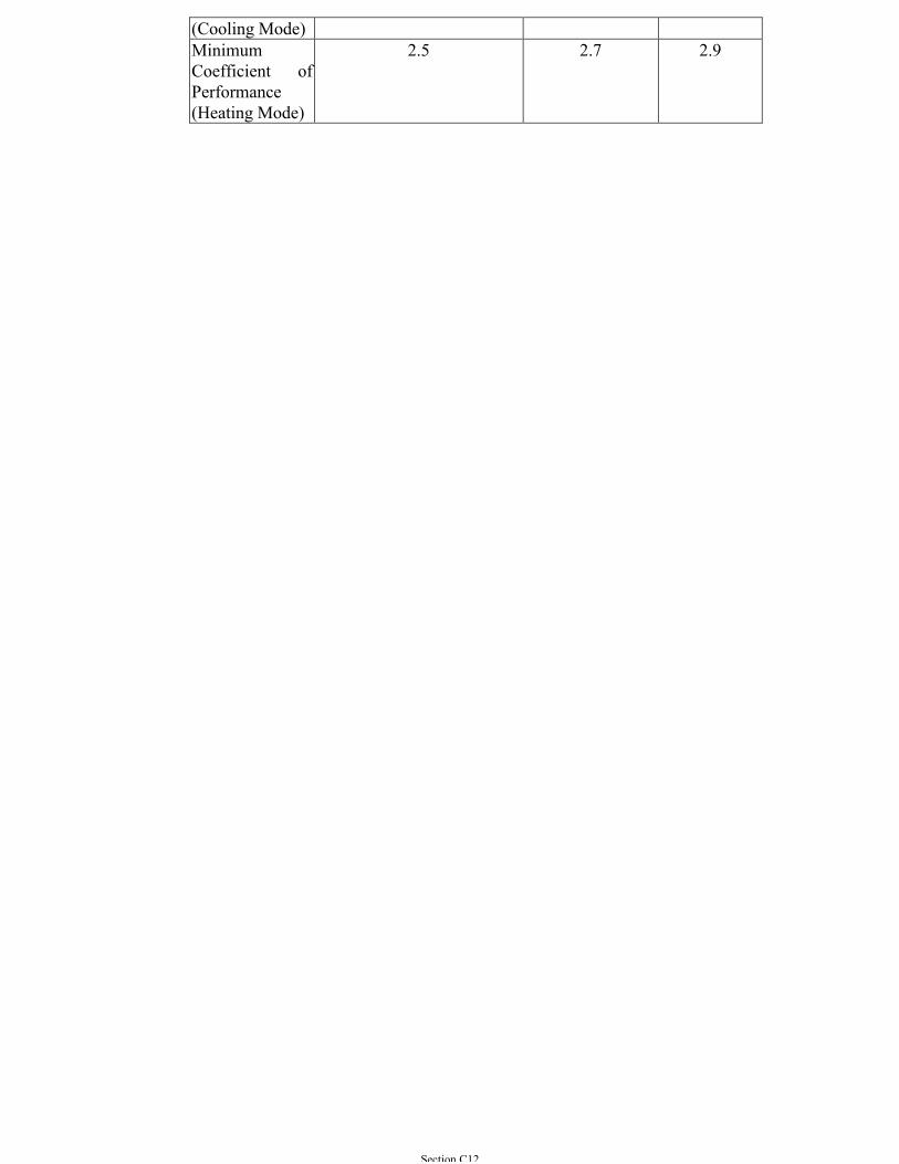
Section C12
(Cooling Mode)MinimumCoefficient ofPerformance(Heating Mode)
2.5 2.7 2.9
Section C13
SECTION C13
WATER HANDLING EQUIPMENT
C13.1 FRESH WATER PUMPS
C13.1.1 Type
(a) Pumps for chilled water circulation or other fresh waterpumping duties unless otherwise specified, shall be of one ofthe following types:
(i) Centrifugal type with volute casing split on thecentreline of the shaft with suction and deliveryconnections flanged and fitted to the non-removable halfof the casing, or
(ii) End suction type, the pump set shall be installed withspacer type coupling so that the pump impeller can bedismantled from the motor side for servicing withoutdisruption of the pipe-work nor dismounting the motor,or
(iii) Vertical spindle type centrifugal pump with end suctionat the bottom.
(b) Where large static heads have to be pumped against, type(a)(ii) or (a)(iii) shall be used in multi-stage configurations.Generally the type of pump required will be specified in theParticular Specifications and/or in the Tender Drawings.However, if this is not so, the type as detailed in (a)(ii) aboveshall be installed if suitable.
C13.1.2 Materials of Construction
Unless otherwise specified, the materials of construction of the pumpsshall be as follows:
(a) Casing: Cast iron(b) Impeller: Zinc free bronze
(*cast iron or stainless steel)(c) Shaft: Carbon steel (*stainless steel)(d) Sleeves: Bronze (*stainless steel)(e) Casing rings: Bronze (*stainless or cast iron)(f) Shaft nuts: Bronze(g) Stuffing box housing: Cast iron(h) Glands: Carbon steel(i) Lantern rings: Bronze
*Alternative materials subject to the approval of the ArchitectNote 1: Stainless steel shall be used for water with temperature >28 oC.
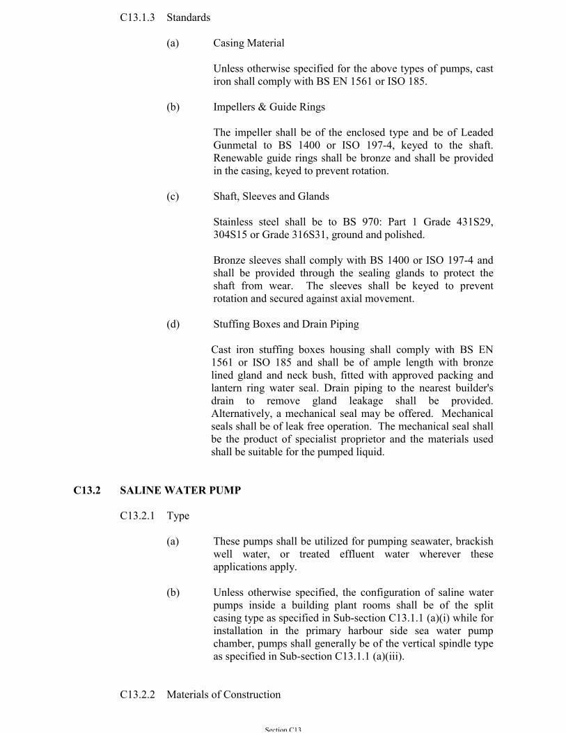
Section C13
C13.1.3 Standards
(a) Casing Material
Unless otherwise specified for the above types of pumps, castiron shall comply with BS EN 1561 or ISO 185.
(b) Impellers & Guide Rings
The impeller shall be of the enclosed type and be of LeadedGunmetal to BS 1400 or ISO 197-4, keyed to the shaft.Renewable guide rings shall be bronze and shall be providedin the casing, keyed to prevent rotation.
(c) Shaft, Sleeves and Glands
Stainless steel shall be to BS 970: Part 1 Grade 431S29,304S15 or Grade 316S31, ground and polished.
Bronze sleeves shall comply with BS 1400 or ISO 197-4 andshall be provided through the sealing glands to protect theshaft from wear. The sleeves shall be keyed to preventrotation and secured against axial movement.
(d) Stuffing Boxes and Drain Piping
Cast iron stuffing boxes housing shall comply with BS EN1561 or ISO 185 and shall be of ample length with bronzelined gland and neck bush, fitted with approved packing andlantern ring water seal. Drain piping to the nearest builder'sdrain to remove gland leakage shall be provided.Alternatively, a mechanical seal may be offered. Mechanicalseals shall be of leak free operation. The mechanical seal shallbe the product of specialist proprietor and the materials usedshall be suitable for the pumped liquid.
C13.2 SALINE WATER PUMP
C13.2.1 Type
(a) These pumps shall be utilized for pumping seawater, brackishwell water, or treated effluent water wherever theseapplications apply.
(b) Unless otherwise specified, the configuration of saline waterpumps inside a building plant rooms shall be of the splitcasing type as specified in Sub-section C13.1.1 (a)(i) while forinstallation in the primary harbour side sea water pumpchamber, pumps shall generally be of the vertical spindle typeas specified in Sub-section C13.1.1 (a)(iii).
C13.2.2 Materials of Construction
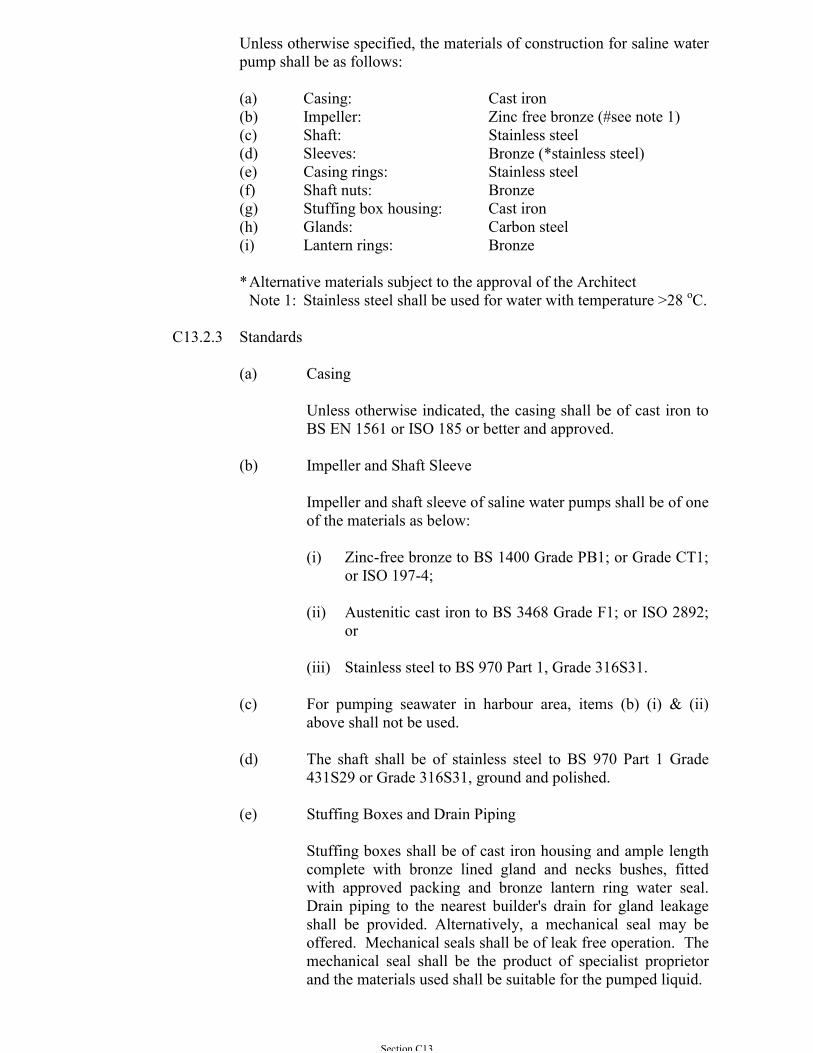
Section C13
Unless otherwise specified, the materials of construction for saline waterpump shall be as follows:
(a) Casing: Cast iron(b) Impeller: Zinc free bronze (#see note 1)(c) Shaft: Stainless steel(d) Sleeves: Bronze (*stainless steel)(e) Casing rings: Stainless steel(f) Shaft nuts: Bronze(g) Stuffing box housing: Cast iron(h) Glands: Carbon steel(i) Lantern rings: Bronze
*Alternative materials subject to the approval of the ArchitectNote 1: Stainless steel shall be used for water with temperature >28 oC.
C13.2.3 Standards
(a) Casing
Unless otherwise indicated, the casing shall be of cast iron toBS EN 1561 or ISO 185 or better and approved.
(b) Impeller and Shaft Sleeve
Impeller and shaft sleeve of saline water pumps shall be of oneof the materials as below:
(i) Zinc-free bronze to BS 1400 Grade PB1; or Grade CT1;or ISO 197-4;
(ii) Austenitic cast iron to BS 3468 Grade F1; or ISO 2892;or
(iii) Stainless steel to BS 970 Part 1, Grade 316S31.
(c) For pumping seawater in harbour area, items (b) (i) & (ii)above shall not be used.
(d) The shaft shall be of stainless steel to BS 970 Part 1 Grade431S29 or Grade 316S31, ground and polished.
(e) Stuffing Boxes and Drain Piping
Stuffing boxes shall be of cast iron housing and ample lengthcomplete with bronze lined gland and necks bushes, fittedwith approved packing and bronze lantern ring water seal.Drain piping to the nearest builder's drain for gland leakageshall be provided. Alternatively, a mechanical seal may beoffered. Mechanical seals shall be of leak free operation. Themechanical seal shall be the product of specialist proprietorand the materials used shall be suitable for the pumped liquid.
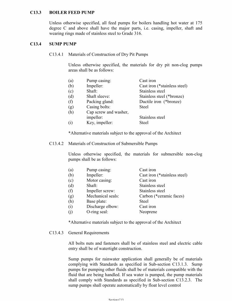
Section C13
C13.3 BOILER FEED PUMP
Unless otherwise specified, all feed pumps for boilers handling hot water at 175degree C and above shall have the major parts, i.e. casing, impeller, shaft andwearing rings made of stainless steel to Grade 316.
C13.4 SUMP PUMP
C13.4.1 Materials of Construction of Dry Pit Pumps
Unless otherwise specified, the materials for dry pit non-clog pumpsareas shall be as follows:
(a) Pump casing: Cast iron(b) Impeller: Cast iron (*stainless steel)(c) Shaft: Stainless steel(d) Shaft sleeve: Stainless steel (*bronze)(f) Packing gland: Ductile iron (*bronze)(g) Casing bolts: Steel(h) Cap screw and washer,
impeller: Stainless steel(i) Key, impeller: Steel
*Alternative materials subject to the approval of the Architect
C13.4.2 Materials of Construction of Submersible Pumps
Unless otherwise specified, the materials for submersible non-clogpumps shall be as follows:
(a) Pump casing: Cast iron(b) Impeller: Cast iron (*stainless steel)(c) Motor casing: Cast iron(d) Shaft: Stainless steel(f) Impeller screw: Stainless steel(g) Mechanical seals: Carbon (*ceramic faces)(h) Base plate: Steel(i) Discharge elbow: Cast iron(j) O-ring seal: Neoprene
*Alternative materials subject to the approval of the Architect
C13.4.3 General Requirements
All bolts nuts and fasteners shall be of stainless steel and electric cableentry shall be of watertight construction.
Sump pumps for rainwater application shall generally be of materialscomplying with Standards as specified in Sub-section C13.1.3. Sumppumps for pumping other fluids shall be of materials compatible with thefluid that are being handled. If sea water is pumped, the pump materialsshall comply with Standards as specified in Sub-section C13.2.3. Thesump pumps shall operate automatically by float level control
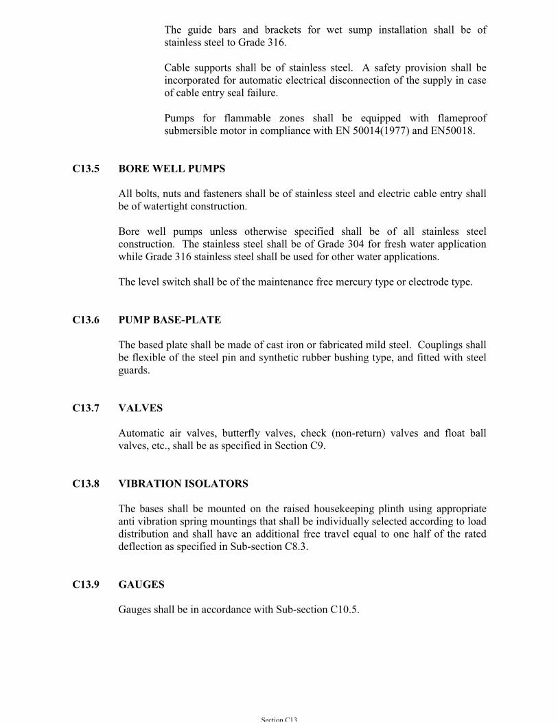
Section C13
The guide bars and brackets for wet sump installation shall be ofstainless steel to Grade 316.
Cable supports shall be of stainless steel. A safety provision shall beincorporated for automatic electrical disconnection of the supply in caseof cable entry seal failure.
Pumps for flammable zones shall be equipped with flameproofsubmersible motor in compliance with EN 50014(1977) and EN50018.
C13.5 BORE WELL PUMPS
All bolts, nuts and fasteners shall be of stainless steel and electric cable entry shallbe of watertight construction.
Bore well pumps unless otherwise specified shall be of all stainless steelconstruction. The stainless steel shall be of Grade 304 for fresh water applicationwhile Grade 316 stainless steel shall be used for other water applications.
The level switch shall be of the maintenance free mercury type or electrode type.
C13.6 PUMP BASE-PLATE
The based plate shall be made of cast iron or fabricated mild steel. Couplings shallbe flexible of the steel pin and synthetic rubber bushing type, and fitted with steelguards.
C13.7 VALVES
Automatic air valves, butterfly valves, check (non-return) valves and float ballvalves, etc., shall be as specified in Section C9.
C13.8 VIBRATION ISOLATORS
The bases shall be mounted on the raised housekeeping plinth using appropriateanti vibration spring mountings that shall be individually selected according to loaddistribution and shall have an additional free travel equal to one half of the rateddeflection as specified in Sub-section C8.3.
C13.9 GAUGES
Gauges shall be in accordance with Sub-section C10.5.
Section C13
C13.10 DRAIN AND VENT
The drain vent shall be built-in complete with a drain plug except where the pumpis inherently self-venting, the drain and drip connection valves and air cock shallcomply with Section C9.
C13.11. FLANGED CONNECTIONS
Pumps shall have flanged connections conforming to the Table of BS 4504 or ISO7005 as appropriate to the maximum working pressure. Taper pieces shall beprovided where necessary for connection to pipe-work.
C13.12 WATER FILTERS
The materials used in water filters shall not corrode or cause corrosion in the waterand shall generally be as specified for water-cooled condensers and water chillers.
C13.13 SEA WATER STRAINER
The unit shall be completed with a motor-controlled continuously rotating innerdrum and equipped with an automatic backwash arrangement.
The unit body shall be provided with an inspection opening for visual checking. Inaddition a drain opening with drain valve shall be provided at the lower part andconnected to the nearest floor drain.
The straining element shall be of stainless steel Grade 316 and shall be of the typeand size suitable for removal of materials as specified in the ContractDrawing/Particular Specification. A motor shall drive this inner drum with suitablegeared facilities that shall be mounted on the top of the strainer body.
The body of the auto-strainer shall be of stainless steel grade 316 or if approved ofcast iron to BS EN 1561 or ISO 185 or ASTM A436 Grade 1B or ASTM 278 Class40 construction with BS970 Part 1 Grade 316 stainless steel liner, housing a rotatingtapered drum attached to a stainless steel shaft of Grade 316. The unit shall besuitable in operation under a pressure of 1034 kPa at 65 oC.
The automatic control of backwash arrangement shall comprise a motor-controlledvalve on the outlet and an adjustable timer and differential pressure switch set to amaximum pressure drop allowed to regulate the frequency of backwash. Suchcontrol shall form an integral part of the Central Control and Monitoring System(CCMS) if available.
The inner drum driving motor shall be drip proof squirrel cage motor.
C13.14 FEED AND EXPANSION FACILITY
C13.14.1 General
Section C13
For the purpose of this General Specification, the following definitionsshall apply:
(a) Cistern - An open top vessel(b) Water Tank - A closed vessel
C13.14.2 Types of Cistern and Tank
(a) Cisterns and tanks shall be of one of the following types asbelow:
(i) Welded or riveted mild steel, to BS 417: Part 2 Grade A,heavily galvanized after manufacture.
(ii) Pressed steel sectional to BS 1564, heavily galvanizedafter manufacture.
(iii) Fibre-glass or plastics, for cisterns not exceeding 500litre capacity to BS 4213.
(b) Pressed steel tanks shall be of the externally flanged type andcomplete with all necessary tie rods. Galvanized mild steelcisterns and pressed steel tanks shall be cleaned and paintedinternally with two coats of an approved bituminous or epoxysolution or shall receive other such internal treatment asindicated.
(c) Covers to Cisterns
Each cistern shall be provided with a loose cover formed insections not exceeding 2m long and 1m wide. Covers forplastic or fibre-glass cisterns shall be of the same material asthe cistern body.
(d) Connections
Connections to mild steel cisterns and tanks shall be made bymeans of bossed, screwed flanges or pads and studs.Connections on mild steel cisterns shall be welded beforegalvanizing. Flanges shall comply with BS 4504 PN6 toPN40 as appropriate or ISO 7005.
C13.15 PLATE TYPE HEAT EXCHANGERS
The specification of plate type heat exchangers shall be in accordance with Sub-section C6.15 of this General Specification.
Related Documents