GENERAL PURPOSE THERMAL MASS FLOW METERS TSI ® SERIES 5200/5300 ASCII COMMAND SET P/N 6011697, REVISION B DECEMBER 2019

Welcome message from author
This document is posted to help you gain knowledge. Please leave a comment to let me know what you think about it! Share it to your friends and learn new things together.
Transcript

GENERAL PURPOSE
THERMAL MASS FLOW METERS
TSI®
SERIES 5200/5300
ASCII COMMAND SET
P/N 6011697, REVISION B
DECEMBER 2019

iii
GENERAL PURPOSE
THERMAL MASS FLOW METERS
TSI®
SERIES 5200/5300
ASCII COMMAND SET
P/N 6011697, REVISION B
DECEMBER 2019
U.S. & INTERNATIONAL TSI Instruments Ltd. (UK)
Sales and Customer Service: Sales and Customer Service:
(800) 680-1220 / +1(651) 490-2860 +44 (0) 1494 459200
Fax:
+1(651) 490-3824

iv
(This page intentionally left blank)
v
Copyright
TSI Incorporated / 2019 / All rights reserved.
Address
TSI Incorporated, 500 Cardigan Road, Shoreview, MN 55126 USA
Trademarks
TSI and the TSI logo are registered trademarks of TSI Incorporated.
FLO-Sight is a trademark of TSI Incorporated.
HyperTerminal is a registered trademark of Hilgraeve, Incorporated.
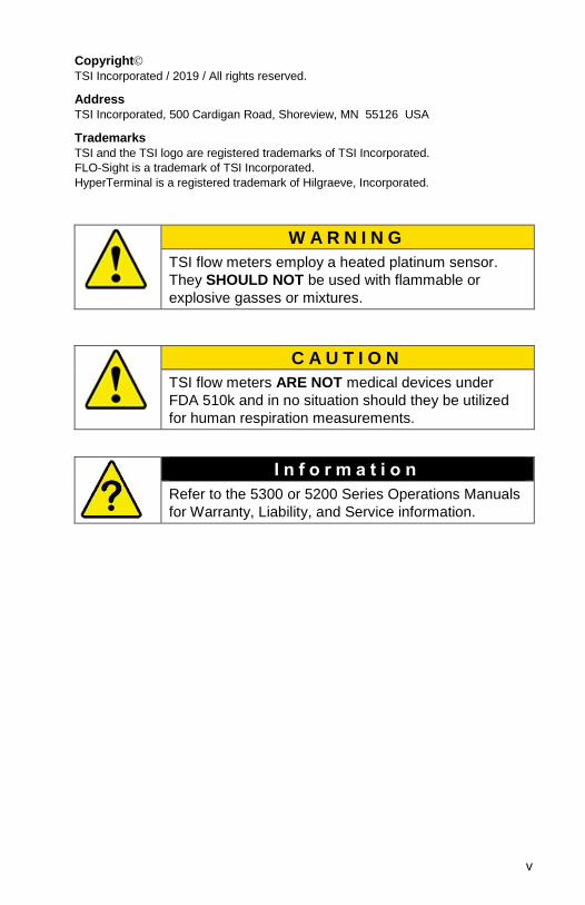
W A R N I N G
TSI flow meters employ a heated platinum sensor.
They SHOULD NOT be used with flammable or
explosive gasses or mixtures.
C A U T I O N
TSI flow meters ARE NOT medical devices under
FDA 510k and in no situation should they be utilized
for human respiration measurements.
I n f o r m a t i o n
Refer to the 5300 or 5200 Series Operations Manuals
for Warranty, Liability, and Service information.

vi
(This page intentionally left blank)

vii
CONTENTS
Chapter 1 ............................................................................................. 1
FLOW METER IDENTIFICATION .................................................... 1
Meter Front ....................................................................................... 1 Meter Back ........................................................................................ 1
Chapter 2 ............................................................................................. 3
CONNECTING COMPUTER TO FLOW METER............................. 3
Direct USB NDIS Interface ............................................................... 3 Steps to Establish Communication over NDIS .............................. 3
RS232 Communication Utilizing a USB A to RS232 Adapter .......... 7
Chapter 3 ........................................................................................... 11
ASCII PROTOCOL ......................................................................... 11
Command Format ........................................................................... 11
Chapter 4 ........................................................................................... 13
COMMAND SET ............................................................................. 13
Command Set Summary ................................................................ 13 Commands for Flow Rate, Temperature, Pressure, and Volume13 Measurement Setup Commands ................................................. 13 Miscellaneous Commands .......................................................... 14 Display Commands ..................................................................... 15
Command Set Detailed................................................................... 16 DmFTPnnnn ................................................................................ 16 DmFTPHLInnnn ........................................................................... 19 TRESET ...................................................................................... 19 Vmnnnn ....................................................................................... 20 SBTxnnn.nn (Series 5300) SBTxnn.nnn (Series 5200) ...... 22 SETxnnn.nn (Series 5300) SETxnn.nnn (Series 5200) ...... 23 CBT ............................................................................................. 23 CET ............................................................................................. 23 SSRnnnn ..................................................................................... 24 SGn SGMmm .............................................................................. 24 SUn .............................................................................................. 25 SSTnn.nn ..................................................................................... 26 SSPnnn.nn .................................................................................. 27 SDU2 ........................................................................................... 27 LPZ .............................................................................................. 27 SCHx ........................................................................................... 27 SCDx ........................................................................................... 28 SCEx ........................................................................................... 28

viii
Rxx ............................................................................................... 29 DEFAULT .................................................................................... 30 SN ................................................................................................ 30 MN ............................................................................................... 30 REV.............................................................................................. 30 HREV ........................................................................................... 31 DATE ........................................................................................... 31 ? ................................................................................................... 31 SUSTRxxxxxxxx .......................................................................... 31 RUSTR ........................................................................................ 32 SALIASxxxxxxxxxxxxxxxx ........................................................... 32 RALIAS ........................................................................................ 32 BREAK ......................................................................................... 32 SBAUDnnnnnn ............................................................................ 33 RBAUD ........................................................................................ 33 SCREENSHOT ............................................................................ 33 SURnnnn ..................................................................................... 34
Chapter 5 ........................................................................................... 35
TROUBLESHOOTING ................................................................... 35
FREQUENTLY ASKED QUESTIONS ............................................ 36
TECHNICAL CONTACTS .............................................................. 37
Appendix A ....................................................................................... 39
ERROR CODES ............................................................................. 39
Appendix B ....................................................................................... 41
FACTORY DEFAULT PARAMETERS .......................................... 41
1
Chapter 1
Flow Meter Identification
Meter Front
Meter Back
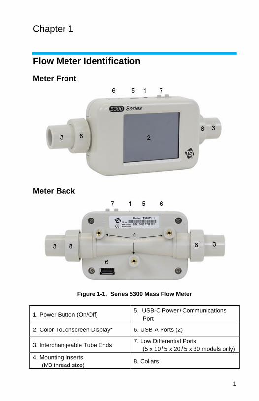
Figure 1-1. Series 5300 Mass Flow Meter
1. Power Button (On/Off) 5. USB-C Power / Communications
Port
2. Color Touchscreen Display* 6. USB-A Ports (2)
3. Interchangeable Tube Ends 7. Low Differential Ports
(5 x 10 / 5 x 20 / 5 x 30 models only)
4. Mounting Inserts
(M3 thread size) 8. Collars

Chapter 1 2
(This page intentionally left blank)
3
Chapter 2
Connecting Computer to Flow Meter
The 5000 Series can establish communication with a computer over
either a direct USB link utilizing a NDIS driver or over RS232 using a
USB to RS232 converter.
Direct USB NDIS Interface
Using the direct link USB interface is the preferred method to
establish communication. This interface is fast and only requires a
single USB cable between the meter and the computer. The same
cable will both power and transfer data. This connection will utilize a
standard USB driver called the NDIS driver.
For this connection to function, the NDIS driver needs to be loaded
onto the computer. This can be easily accomplished by installing the
free TSI Basic flow software package called FLO-Sight™. As part of
the installation, the install package will place the NDIS driver on the
computer. Refer to the main instrument manual for details on how to
install free TSI FLO-Sight™ software.
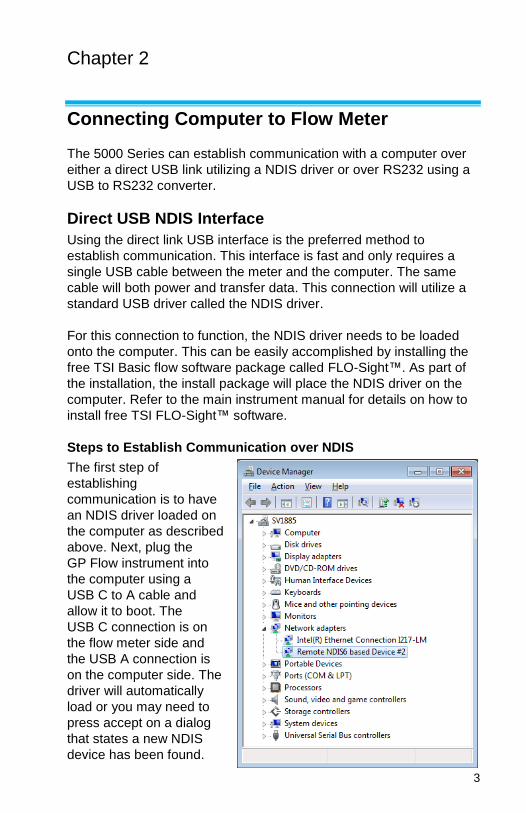
Steps to Establish Communication over NDIS
The first step of
establishing
communication is to have
an NDIS driver loaded on
the computer as described
above. Next, plug the
GP Flow instrument into
the computer using a
USB C to A cable and
allow it to boot. The
USB C connection is on
the flow meter side and
the USB A connection is
on the computer side. The
driver will automatically
load or you may need to
press accept on a dialog
that states a new NDIS
device has been found.

Chapter 2 4
The driver function can be confirmed by looking into the computer’s
device manager. The instrument will show up as a Remote NDIS
device under Network Adapters (see screen capture below).
The next step to test the communication is to open up a terminal
program and establish a TCP/IP winsock connection. The example
below is using HyperTerminal® Terminal program.
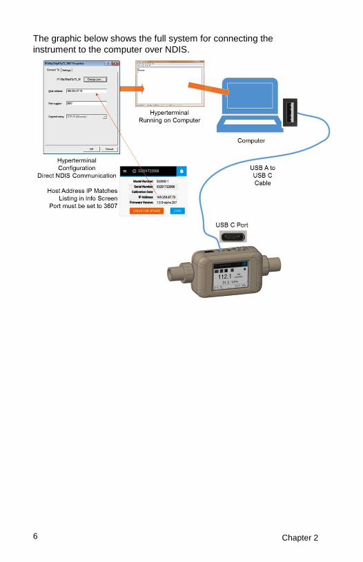
First, determine the device’s IP address using the instrument screen
by pressing the info tag. Each GP Flow insturment will have an
unique IP address.
Next, enter the IP
address into the
terminal’s connection
dialog. Set the connection
to TCP/IP and enter the
port number of 3607. This
is shown in the
HyperTerminal®
Connection dialog.
Press
IP Address

Connecting Computer to Flow Meter 5
Now, commands typed into the terminal will be relayed to the
instrument and responses presented in the terminal screen. If the
connection is working, the meter will respond to a question mark
command “?” with “OK”.
Chapter 2 6
The graphic below shows the full system for connecting the
instrument to the computer over NDIS.

Connecting Computer to Flow Meter 7
RS232 Communication Utilizing a USB A to RS232 Adapter
Another method for communicating to the GP Flow instrument is to
utilize a USB to RS232 adapter and then communicate to the
computer using RS232 protocols.
The first step is to connect a USB to RS232 converter to the GP Flow
instrument. The converter must be based on the FTD based drivers
for it to function with the GP Flow instrument. TSI sells a converter
tested to work with the instrument P/N 5000-RS232. After attaching
the converter, the GP Flow instrument must be rebooted. See
graphic below.
I n f o r m a t i o n
The 5000 Series instrument must be rebooted after
attaching the USB to RS232 adapter.
Once the meter has been rebooted, a DB9 Null modem serial cable
can be attached to the computer.
I n f o r m a t i o n
The serial cable between the GP Flow instrument and
the computer must be a null modem cable.

Chapter 2 8
Once the RS232 connection has been created between the GP Flow
instrument and the computer, that connection can be tested using a
Terminal program.
The RS232 Settings to be
entered into the terminal
program are shown below.
RS232 Settings:
Baud Rate ......... 115,200 k
Data Bits ............ 8
Parity ................. None
Stop Bits ............ 1
Flow Control ...... None
Enter the RS232 settings into
the terminal’s connection
dialog. This is shown in the
HyperTerminal® Connection
dialog shown at right.
Now, commands typed into the terminal will be relayed to the
instrument and responses presented in the terminal screen. If the
connection is working, the meter will respond to a question mark
command “?” with “OK”.

Connecting Computer to Flow Meter 9
Note that the RS232 baud rate is factory set at 115,200. This rate can
be changed to 38,400 to be backwards compatible with the 4000
Series instrument. See the baud rate commands in the manual for
steps in changing the baud rate.
The graphic below shows the full system for connecting the
instrument to the computer over RS232.

Chapter 2 10
(This page intentionally left blank)

11
Chapter 3
ASCII Protocol
Command Format
The serial interface commands in this manual are designated by the
bold font (ex. DmFTPnnnn). The commands are case-sensitive.
Upper case letters are used throughout the command set except as
designated.
The TSI Series 5XXX use ASCII characters as the input command
set. Each command sent to the flow meter must be terminated by a
carriage return (CR = 0x0d). Line feeds (LF = 0x0a) are ignored.
Select commands allow you to choose either ASCII or binary format
for the returned data. Binary data transfers allow for faster operation.
The TSI Series 5XXX flow meters send an acknowledge sequence to
confirm that the command was received. For ASCII commands, the
acknowledge sequence is “OK” <CR><LF>. For binary commands, a
single byte, 0x00, is returned.
The ASCII command set for the Series 4000 / 4100 flow meters
(4000-4100-RS-Command-Set P/N 1980340) is backwards
compatible with the TSI Series 5XXX flow meters. This manual lists
which commands also work with the Series 4000 / 4100 flow meters
and also include additional commands specifically for the additional
functions of the 5XXX series.

Chapter 3 12
(This page intentionally left blank)

13
Chapter 4
Command Set
Command Set Summary
Commands for Flow Rate, Temperature, Pressure, and Volume
Command Description
Backward Compatible with 4000/4100 Series
DmFTPnnnn Returns flow rate, temperature, and absolute pressure data at an interval equal to the sample rate.
Yes
DmFTPHLInnnn Returns flow rate, temperature, absolute pressure, humidity, low pressure and totalizer data at an interval equal to the sample rate.
No
Vmnnnn Returns a volume measurement by integrating flow rate over time.
Yes
Measurement Setup Commands
Command Description
Backward Compatible with 4000/4100 Series
SBTxnnn.nn Sets the begin-trigger level for starting data acquisition.
Yes
SETxnnn.nn Sets the end-trigger level for stopping data acquisition.
Yes
CBT Clears the begin-trigger level.
Yes
CET Clears the end-trigger level. Yes
SSRnnnn Sets the sample rate at which the data is returned.
Yes
14 Chapter 4
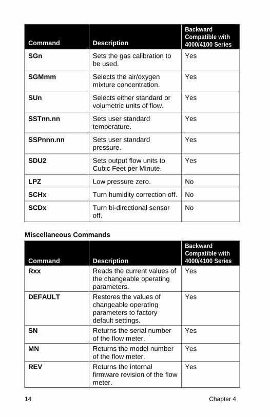
Command Description
Backward Compatible with 4000/4100 Series
SGn Sets the gas calibration to be used.
Yes
SGMmm Selects the air/oxygen mixture concentration.
Yes
SUn Selects either standard or volumetric units of flow.
Yes
SSTnn.nn Sets user standard temperature.
Yes
SSPnnn.nn Sets user standard pressure.
Yes
SDU2 Sets output flow units to Cubic Feet per Minute.
Yes
LPZ Low pressure zero. No
SCHx Turn humidity correction off. No
SCDx Turn bi-directional sensor off.
No
Miscellaneous Commands
Command Description
Backward Compatible with 4000/4100 Series
Rxx Reads the current values of the changeable operating parameters.
Yes
DEFAULT Restores the values of changeable operating parameters to factory default settings.
Yes
SN Returns the serial number of the flow meter.
Yes
MN Returns the model number of the flow meter.
Yes
REV Returns the internal firmware revision of the flow meter.
Yes

Command Set 15
Command Description
Backward Compatible with 4000/4100 Series
HREV Returns the internal hardware revision of the flow meter.
No
DATE Returns the date of the last calibration.
Yes
? Returns “OK” to tell if the flow meter is communicating.
Yes
SUSTRxxxxxxxx Set user string. Yes
RUSTR Read user string. Yes
SALIASxxxxxx xxxxxxxxxx
Set meter alias. No
RALIAS Read user string. No
BREAK Stop the current sending of data.
No
SBAUDnnnnnn Set RS232 baud rate. No
RBAUD Read RS232 baud rate. No
Display Commands
Command Description
Backward Compatible with 4000/4100 Series
SURnnnn Sets the update rate for the LCD display.
Yes

16 Chapter 4
Command Set Detailed
DmFTPnnnn
Backwards compatible with Series 4000 / 4100 flow meters.
Returns Flow, Temperature, and Pressure data at an interval equal to
the sample rate.
The data is returned in the order of Flow, Temperature, and Pressure.
All three measurements may be requested or a combination of the
three as indicated below.
D Denotes data transfer.
m Denotes data format: A = ASCII, B = binary,
C = ASCII followed by CR and LF.
F Requests a flow reading (replace with lower case “x” if a
flow reading is not desired).
T Requests a temperature reading (replace with a lower case
“x” if a temperature reading is not desired).
P Requests a pressure reading (replace with a lower case “x”
if a pressure reading is not required).
nnnn Denotes maximum number of samples to return, range is
1 to 1000. (“0500” denotes 500 readings, leading zeroes
must be included).
Example 1) DAFxP0250
Requests 250 readings of flow and pressure data in ASCII format.
Example 2) DBxTx1000
Requests 1000 readings of temperature in binary format.
Flow data is returned in units of Std. L/min or L/min (see SUn
command).
Temperature data is returned in units of °C.
Pressure data is returned in units of kPa.
Before initiating this command, the sample interval, gas calibration,
and flow units should be set.
The sample interval between data points is set using the SSRnnnn
command.
The gas calibration is set using the SGn command.
The units of standard or volumetric flow is set using the SUn
command.

Command Set 17
The data can be returned in either ASCII or binary.
If ASCII mode is chosen, the acknowledge sequence is “OK”
<CR><LF>. If the command generated an error, an error code
“ERRn” <CR><LF> will be returned where n represents an error code
0 through 9. See Appendix A for a list of possible error codes. The
readings returned are separated by commas and the termination
sequence is a <CR><LF>. The Series 4000 / 5300 sends two decimal
places, and the Series 4100 / 5200 sends three decimal places for
flow rate.
If binary mode is chosen, a single byte, 0x00, will be returned as a
command acknowledgment. If a command generated an error, a
single byte will be returned in place of the acknowledgment byte. See
Appendix A for a list of error codes. Each reading returns two bytes.
The most significant byte is returned first. Flow rate data is returned
as an unsigned integer (0 to 65535) that has been multiplied by 100
(for Series 4000) or by 1000 (Series 4100). Temperature data is
returned as a signed integer (-32768 to 32767) that has been
multiplied by 100. Pressure data is returned as an unsigned integer
that has been multiplied by 100. To convert the returned data back to
its original form, divide the data by 100. Binary transfers terminate by
returning two bytes in the form 0xff. Check the first reading in each
block of data returned (flow, temperature, and pressure) from the unit,
for the terminating sequence. No termination sequence will be sent if
an error condition occurred.
Special note: A temperature reading of –0.01C would be
transmitted as 0xff and could signal an early
termination if flow readings were disabled.
If no begin-trigger is set, the data acquisition begins immediately
upon processing of the command. If a begin-trigger is set (set with
SBTxnnn.nn), the data acquisition begins as soon as the begin-
trigger condition is detected. If no end-trigger is set, then nnnn
samples will be used in the data set. If an end-trigger is set (set with
SETxnnn.nn), then the acquisition will stop either when the end-
trigger condition is detected or when nnnn samples have been
acquired; whichever comes first. After the command is finished, a
termination sequence is sent to signal the end of the transfer.
Example 3) SSR0010
Set sample rate to one average sample every 10 ms.
Flow meter returns OK <CR><LF>

18 Chapter 4
SG1 Use the oxygen gas calibration.
Flow meter returns OK <CR><LF>
SBTF+001.00
Begin sample by triggering on increasing flow at 1.0 Std. L/min.
Flow meter returns OK <CR><LF>
DAFxx0005 Request 5 samples of flow in ASCII format.
Flow meter returns OK <CR><LF>
Flow meter returns flow data as follows.
1.10,1.20,1.25,1.23,1.20<CR><LF>
Example 4) DBFxx0005
Request 5 samples of flow in binary format.
An example of the data that could be returned is as follows.
0x00 0x33 0x09 0x33 0x1f 0x33 0x25 0x33 0x2d 0x33 0x2e 0xff 0xff
After conversion, the data would look like:
130.65 130.87 130.93 131.01 131.02
Example 5) DCFTx0005
Request five samples of flow and temperature in ASCII format but
with <CR> and <LF> following each data set.
Returns data as follows.
1.10,23.45<CR><LF>
1.20,23.53<CR><LF>
1.25,23.48<CR><LF>
1.23,23.39<CR><LF>
1.20,23.50<CR><LF>

Command Set 19
DmFTPHLInnnn
Returns Flow, Temperature, Absolute Pressure, Humidity, Low
Pressure, and Totalizer data at an interval equal to the sample rate.
The data is returned in the order of Flow, Temperature, Absolute
Pressure, Humidity, Low Pressure, and Totalizer. All six
measurements may be requested or a combination of the three as
indicated below.
D Denotes data transfer.
m Denotes data format: A = ASCII, B = binary,
C = ASCII followed by <CR> and <LF>.
F Requests a flow reading (replace with lower case “x” if a
flow reading is not desired).
T Requests a temperature reading (replace with a lower case
“x” if a temperature reading is not desired).
P Requests a pressure reading (replace with a lower case “x”
if a pressure reading is not required).
H Requests a Humidity reading (replace with lower case “x” if
a flow reading is not desired).
L Requests a low pressure reading (replace with a lower case
“x” if a temperature reading is not desired).
I Requests a totalizer reading (replace with a lower case “x”
if a pressure reading is not required).
nnnn Denotes maximum number of samples to return, range is 1
to 1000. (“0500” denotes 500 readings, leading zeroes must
be included).
This command follows all the same rules documented in the
DmFTPnnnn command.
This command has the special case where setting the nnnn to 0000
will result in 30 seconds of streaming data. The total number of data
points will be dependent on sample rate. For example, it the sample
rate is 10 msec, then this command will stream out 300 readings over
30 seconds.
TRESET
Resets the Totalizer measurement counter back to zero.

20 Chapter 4
Vmnnnn
Backwards compatible with Series 4000 / 4100 flow meters.
Returns a volume measurement by integrating flow rate over time.
V Denotes volume measurement
m Denotes data format: A = ASCII, B = binary
nnnn Denotes maximum number of flow samples to integrate,
range is 1 to 9999
(“0500” denotes 500 readings, leading zeroes must be
included)
Example 1) VA2000
Request a single volume reading by integrating a maximum of 2000
flow samples and return data in ASCII format.
Volume data is returned in units of standard liters or volumetric liters (see SUn command).
Before initiating this command, the sample interval, gas calibration,
and volume units should be set.
The sample interval between data points is set using the SSRnnnn
command.
The gas calibration is set using the SGn command.
The units of standard or volumetric is set using the SUn command.
The most common units are volumetric liters.
The data can be returned in either ASCII or binary.
If ASCII mode is chosen, the acknowledge sequence is “OK”
<CR><LF>. If the command generated an error, instead of “OK”
<CR><LF> being returned an error code “ERRn” <CR><LF> will be
returned where n represents an error code 0 through 9. See
Appendix A for a list of possible error codes. The termination
sequence is a <CR><LF>.
If binary mode is chosen, the acknowledge sequence is a single byte
0x00.
If the command generated an error, a single byte error code will be
returned instead of 0x00. See Appendix A for a list of possible error
codes. The reading is represented by 2 bytes. The most significant
byte is returned first. The data is represented as an unsigned integer

Command Set 21
(0 to 65535) that has been multiplied by 100 (Series 4000) or by
1,000 (Series 4100). Therefore, you must divide the integer that is
returned by 100 or 1000 to get the correct result. The termination
sequence for binary is 0xff 0xff.
If no begin-trigger is set, the data acquisition begins immediately
upon processing of the command. If a begin-trigger is set (set with
SBTxnnn.nn), the data acquisition begins as soon as the begin-
trigger condition is detected. If no end-trigger is set, then nnnn
samples will be used in the integral. If an end-trigger is set (set with
SETxnnn.nn), the acquisition will stop either when the end-trigger
condition is detected or when nnnn samples has been acquired;
whichever comes first. After the command is finished, a termination
sequence is sent to signal the end of the transfer.
Example 2) VA1000
Request volume measurement with at most 1000 samples, data
returned in ASCII.
Returns volume data as follows: OK <CR><LF> 130.651 <CR><LF>
Example 3) VB1000
Request volume measurement with at most 1000 samples, data
returned in binary.
Returns data as follows: 0x00 0x33 0x09 0xff 0xff
After conversion, the data would look like: 130.65
22 Chapter 4
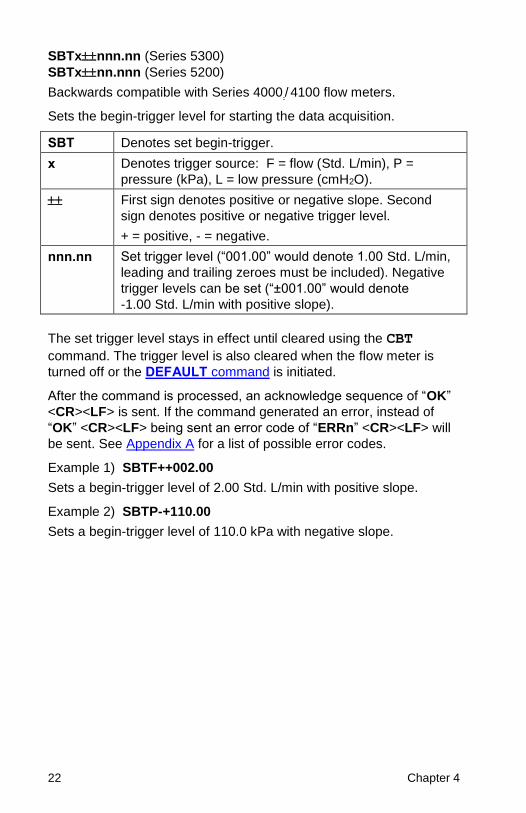
SBTxnnn.nn (Series 5300)
SBTxnn.nnn (Series 5200)
Backwards compatible with Series 4000 / 4100 flow meters.
Sets the begin-trigger level for starting the data acquisition.
SBT Denotes set begin-trigger.
x Denotes trigger source: F = flow (Std. L/min), P =
pressure (kPa), L = low pressure (cmH2O).
First sign denotes positive or negative slope. Second
sign denotes positive or negative trigger level.
+ = positive, - = negative.
nnn.nn Set trigger level (“001.00” would denote 1.00 Std. L/min,
leading and trailing zeroes must be included). Negative
trigger levels can be set (“±001.00” would denote
-1.00 Std. L/min with positive slope).
The set trigger level stays in effect until cleared using the CBT
command. The trigger level is also cleared when the flow meter is
turned off or the DEFAULT command is initiated.
After the command is processed, an acknowledge sequence of “OK”
<CR><LF> is sent. If the command generated an error, instead of
“OK” <CR><LF> being sent an error code of “ERRn” <CR><LF> will
be sent. See Appendix A for a list of possible error codes.
Example 1) SBTF++002.00
Sets a begin-trigger level of 2.00 Std. L/min with positive slope.
Example 2) SBTP-+110.00
Sets a begin-trigger level of 110.0 kPa with negative slope.
Command Set 23
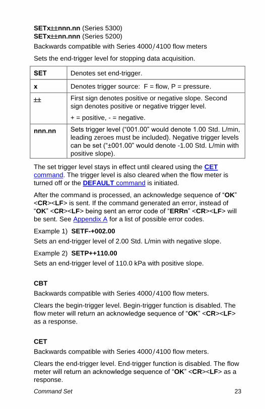
SETxnnn.nn (Series 5300)
SETxnn.nnn (Series 5200)
Backwards compatible with Series 4000 / 4100 flow meters
Sets the end-trigger level for stopping data acquisition.
SET Denotes set end-trigger.
x Denotes trigger source: F = flow, P = pressure.
First sign denotes positive or negative slope. Second
sign denotes positive or negative trigger level.
+ = positive, - = negative.
nnn.nn Sets trigger level (“001.00” would denote 1.00 Std. L/min,
leading zeroes must be included). Negative trigger levels
can be set (“±001.00” would denote -1.00 Std. L/min with
positive slope).
The set trigger level stays in effect until cleared using the CET
command. The trigger level is also cleared when the flow meter is
turned off or the DEFAULT command is initiated.
After the command is processed, an acknowledge sequence of “OK”
<CR><LF> is sent. If the command generated an error, instead of
“OK” <CR><LF> being sent an error code of “ERRn” <CR><LF> will
be sent. See Appendix A for a list of possible error codes.
Example 1) SETF-+002.00
Sets an end-trigger level of 2.00 Std. L/min with negative slope.
Example 2) SETP++110.00
Sets an end-trigger level of 110.0 kPa with positive slope.
CBT
Backwards compatible with Series 4000 / 4100 flow meters.
Clears the begin-trigger level. Begin-trigger function is disabled. The
flow meter will return an acknowledge sequence of “OK” <CR><LF>
as a response.
CET
Backwards compatible with Series 4000 / 4100 flow meters.
Clears the end-trigger level. End-trigger function is disabled. The flow
meter will return an acknowledge sequence of “OK” <CR><LF> as a
response.

24 Chapter 4
SSRnnnn
Backwards compatible with Series 4000 / 4100 flow meters
Sets the sample rate for data returned through the serial port and also
controls the update rate of the linearized analog flow output.
SSR Denotes set sample rate.
nnnn Denotes number of milliseconds per sample, range
1 to 1000.
(“0005” denotes 5 milliseconds per sample, leading
zeroes must be included).
Longer sample rates provide greater flow averaging; whereas, shorter
sample rates provide greater frequency response.
After the command is processed, an acknowledge sequence of “OK”
<CR><LF> is sent. If the command generated an error, an error code
of “ERRn” <CR><LF>will be sent. See Appendix A for a list of
possible error codes.
SGn
SGMmm
Backwards compatible with Series 4000 / 4100 flow meters.
Sets the gas calibration to be used or sets the air/oxygen mixture
concentration.
Models 53XX Only
SG Denotes set gas calibration.
n Denotes the gas calibration desired; range is 0 to 6
0 = Air, 1 = 100% O2, 3 = 100% CO2, 6 = 100% N2,
Options 2, 4, and 5 are invalid in these models. The
meter display will indicate the current gas calibration.
NOTE: Only select gas calibration for gases in which the
meter is calibrated. Consult the user manual for
list of calibrated gases.
SGM Denotes set air/oxygen mixture concentration.
mm Denotes the amount of oxygen in air. Range is 21% to
99%.
The display will indicate the current gas calibration, either
air or O2. For air/oxygen mixtures, the display will indicate
both air and oxygen.

Command Set 25
Models 52xx Only
SG Denotes set gas calibration.
n Denotes the gas calibration desired; range is 0 to 6,
0 = Air, 1 = 100% O2, 2 = 100% N2O, 3 = 100% CO2,
6 = 100% N2.
Options 4 and 5 are invalid in these models. The meter
display will indicate the current gas calibration.
NOTE: Only select gas calibration for gases in which the
meter is calibrated. Consult the user manual for
list of calibrated gases.
SGM Denotes set air/oxygen mixture concentration.
mm Denotes the amount of oxy gen in air. Range is 21% to
99%.
The display will indicate the current gas calibration, either
air or O2. For air/oxygen mixtures, the display will indicate
both air and oxygen.
After the command is processed, an acknowledge sequence of “OK”
<CR><LF> is sent. If the command generated an error, instead of
“OK” <CR><LF> being sent an error code of “ERRn” <CR><LF> will
be sent. See Appendix A for a list of possible error codes.
SUn
Select either standard or volumetric units of flow for data displayed on
the LCD display and for data received through the serial port.
SU Denotes whether flow is measured in standard units or
volumetric units.
n Denotes which units.
S = standard flow rate, V = volumetric flow rate, U = User
conditions, UT = User temperature conditions, actual
pressure, UP = User pressure conditions, actual
temperature
This will control the units of measure for the gas reading over the
communications port. To change the units of measure shown on the
GUI screen, use the instrument’s touch screen (reference the user
manual).
26 Chapter 4
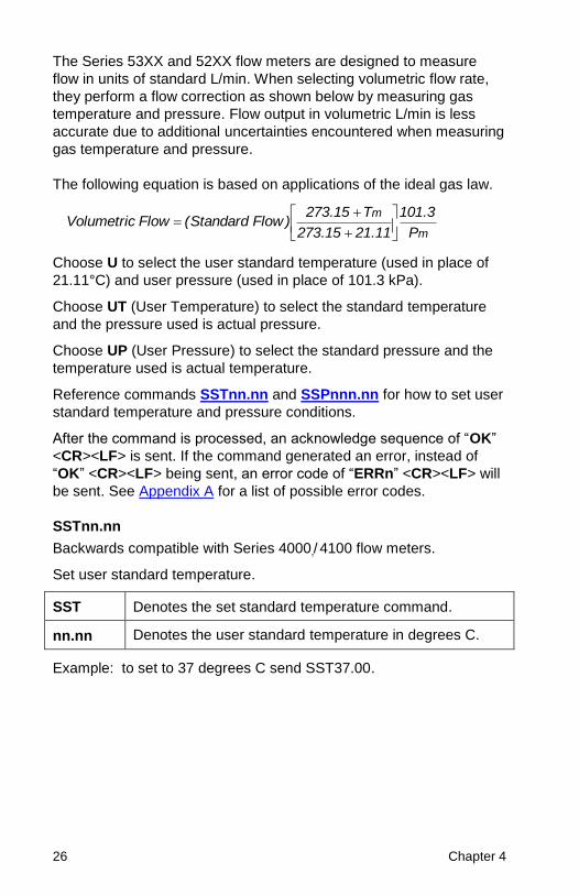
The Series 53XX and 52XX flow meters are designed to measure
flow in units of standard L/min. When selecting volumetric flow rate,
they perform a flow correction as shown below by measuring gas
temperature and pressure. Flow output in volumetric L/min is less
accurate due to additional uncertainties encountered when measuring
gas temperature and pressure.
The following equation is based on applications of the ideal gas law.
m
m
P
3.101
11.2115.273
T15.273)FlowStandard(FlowVolumetric
+
+=
Choose U to select the user standard temperature (used in place of
21.11°C) and user pressure (used in place of 101.3 kPa).
Choose UT (User Temperature) to select the standard temperature
and the pressure used is actual pressure.
Choose UP (User Pressure) to select the standard pressure and the
temperature used is actual temperature.
Reference commands SSTnn.nn and SSPnnn.nn for how to set user
standard temperature and pressure conditions.
After the command is processed, an acknowledge sequence of “OK”
<CR><LF> is sent. If the command generated an error, instead of
“OK” <CR><LF> being sent, an error code of “ERRn” <CR><LF> will
be sent. See Appendix A for a list of possible error codes.
SSTnn.nn
Backwards compatible with Series 4000 / 4100 flow meters.
Set user standard temperature.
SST Denotes the set standard temperature command.
nn.nn Denotes the user standard temperature in degrees C.
Example: to set to 37 degrees C send SST37.00.

Command Set 27
SSPnnn.nn
Backwards compatible with Series 4000 / 4100 flow meters.
Set user standard pressure.
SST Denotes the set standard temperature command.
nnn.nn Denotes the user standard pressure in kPa.
Example: to set standard pressure to 120kPa send SSP120.00
SDU2
Backwards compatible with Series 4000 / 4100 flow meters.
Outputs flow in Cubic Feet per Minute.
SSU2 Denotes set flow units to Cubic Feet per Minute.
This will control the units of measure for the gas reading over the
communications port. To change the units of measure shown on the
GUI screen, use the instrument’s touch screen (reference the user
manual).
LPZ
Zeroes the low pressure transducer
LPZ Denotes set Low pressure zero command.
This command will zero the low pressure transducer. It will reply “OK”
if successful. It will reply “Err” if not successful. If the meter does not
have a low pressure transducer, it will reply with an error.
SCHx
Turn on/off Humidity correction.
SCH Denotes set Humidity compensation command.
x Denotes to turn on or off Humidity compensation.
x= 0 to turn off
x= 1 to turn on
This will turn the humidity compensation on or off.
28 Chapter 4
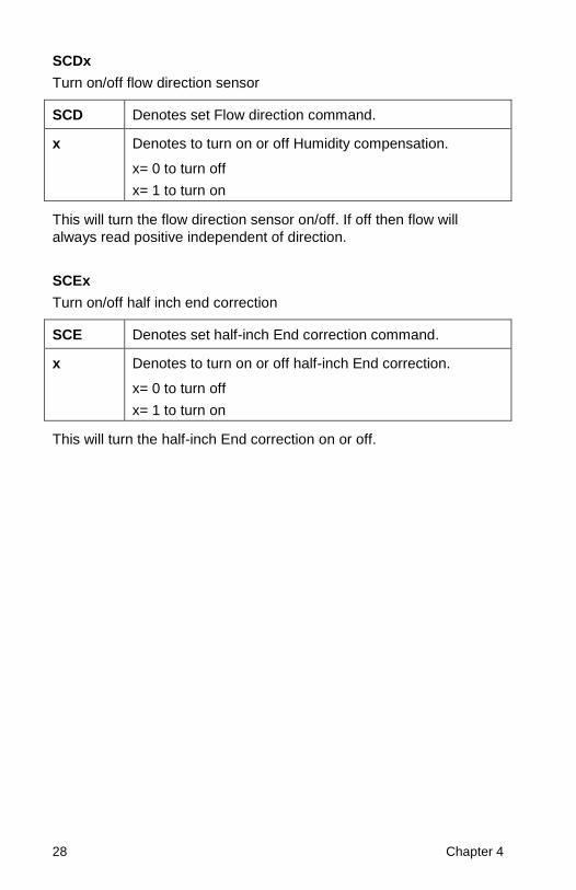
SCDx
Turn on/off flow direction sensor
SCD Denotes set Flow direction command.
x Denotes to turn on or off Humidity compensation.
x= 0 to turn off
x= 1 to turn on
This will turn the flow direction sensor on/off. If off then flow will
always read positive independent of direction.
SCEx
Turn on/off half inch end correction
SCE Denotes set half-inch End correction command.
x Denotes to turn on or off half-inch End correction.
x= 0 to turn off
x= 1 to turn on
This will turn the half-inch End correction on or off.

Command Set 29
Rxx
Partially backwards compatible with Series 4000 / 4100 flow meters.
Reads the current values for sample rate, gas calibration, standard /
volumetric flow units, trigger values, analog output scaling and display
update rate.
R Denotes read current values.
xx xx=SR Denotes sample rate (returns 0 to 1000).
xx=G Denotes gas calibration (returns 0 to 6 for gas
calibration, returns M21 to M99 for air/O2 mixture
concentrations).
xx=U Denotes flow units (returns S, V, U, UT or UP).
xx=BT Denotes begin-trigger value (returns xnnn.nn). If
only one sign is returned, this is the sign of the
slope. A positive trigger level’s sign will not be
returned, only a negative trigger level will return a
sign (-).
xx=ET Denotes end-trigger value (returns xnnn.nn). If
only one sign is returned, this is the sign of the
slope. A positive trigger level’s sign will not be
returned, only a negative trigger level will return a
sign (-).
xx=UR Denotes display update rate (returns 50 to 5000).
xx=ST Denotes user standard temperature (returns
0–99.99).
xx=SP Denotes user standard pressure (returns 0-999.99).
xx=CH Denotes Humidity compensation (0 = off, 1 = on).
xx=CD Denotes Flow direction sensor (0 = off, 1 = on).
xx=CE Denotes half-inch End correction (0 = off, 1 = on).
Returns current settings in ASCII format. Leading zeroes are not
returned.
After the command is processed, an acknowledge sequence of “OK”
<CR><LF> is sent followed by the data. If the command generated
an error, instead of “OK” <CR><LF> being sent an error code of
“ERRn” <CR><LF> will be sent. See Appendix A for a list of possible
error codes.

30 Chapter 4
DEFAULT
Backwards compatible with Series 4000 / 4100 flow meters.
Returns the values for sample rate, calibration gas/gas mixture,
standard / volumetric flow units, display update rate, display mode,
analog zero, and full-scale scaling factors to the factory default
settings. This command also clears both the begin- and end-trigger
values. The default values for the Series 53XX / 52XX operating
parameters are listed in Appendix B.
SN
Backwards compatible with Series 4000 / 4100 flow meters.
Returns the serial number of the flow meter in ASCII. The serial
number is an alpha-numeric string terminated by a <CR><LF>. The
string can be a maximum of 16 characters in length plus the
terminating <CR><LF>.
Example: 53101816001
MN
Backwards compatible with Series 4000 / 4100 flow meters.
Returns the model number of the flow meter in ASCII. The model
number is an alpha-numeric string terminated by a <CR><LF>. The
string can be a maximum of 12 characters in length plus the
terminating <CR><LF>.
Example: 531001
REV
Backwards compatible with Series 4000 / 4100 flow meters.
Returns the internal firmware revision of the flow meter in ASCII. The
revision is an alpha-numeric string terminated by a <CR><LF>. The
string can be a maximum of three characters in length plus the
terminating <CR><LF>.
Example: 1.3

Command Set 31
HREV
Returns the internal hardware revision of the flow meter in ASCII. The
revision is an alpha-numeric string terminated by a <CR><LF>. The
string can be a maximum of three characters in length plus the
terminating <CR><LF>.
Example: A
DATE
Backwards compatible with Series 4000 / 4100 flow meters
Returns the date of the last calibration in ASCII. The format of the
string is “month/day/year”. The date is an alpha-numeric string
terminated by a <CR><LF>. The string can be a maximum of eight
characters in length plus the terminating <CR><LF>.
Example: 12/24/18
?
Backwards compatible with Series 4000 / 4100 flow meters
This is a ping command used to verify if the flow meter is
communicating.
The flow meter will return an acknowledge sequence of “OK”
<CR><LF> as a response. The serial communications indicator will
flash once on the LCD display to indicate that the command was
received.
SUSTRxxxxxxxx
Backwards compatible with Series 4000 / 4100 flow meters.
Set a user-defined string to be stored in the meter.
SUSTR Denotes Set user string command.
xxxxxxxx x = alphanumeric character
Must enter eight characters following the command
NOTE: User string is not reset when the DEFAULT command is
used or during normal recalibration.
32 Chapter 4
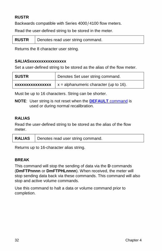
RUSTR
Backwards compatible with Series 4000 / 4100 flow meters.
Read the user-defined string to be stored in the meter.
RUSTR Denotes read user string command.
Returns the 8 character user string.
SALIASxxxxxxxxxxxxxxxx
Set a user-defined string to be stored as the alias of the flow meter.
SUSTR Denotes Set user string command.
xxxxxxxxxxxxxxxx x = alphanumeric character (up to 16).
Must be up to 16 characters. String can be shorter.
NOTE: User string is not reset when the DEFAULT command is
used or during normal recalibration.
RALIAS
Read the user-defined string to be stored as the alias of the flow
meter.
RALIAS Denotes read user string command.
Returns up to 16-character alias string.
BREAK
This command will stop the sending of data via the D commands
(DmFTPnnnn or DmFTPHLnnnn). When received, the meter will
stop sending data back via these commands. This command will also
stop and active volume commands.
Use this command to halt a data or volume command prior to
completion.

Command Set 33
SBAUDnnnnnn
Sets the RS232 baud rate of the instrument, when using the USB to
RS232 converter cable.
SBAUD Denotes the Set Baud command.
nnnnnn Denotes Baud Rate nnnnnn can equal 38400 or 115200.
The instrument needs to be rebooted for the new baud rate to take
effect.
RBAUD
Reads the RS232 baud rate of the instrument, when using the USB to
RS232 converter cable.
RBAUD Denotes the Read Baud command.
Returns a 5- or 6-character string denoting a baud rate of 38400 or
115200.
SCREENSHOT
Saves a screenshot of the current meter to a USB drive.
SCREENSHOT Denotes the Screenshot command.
Returns “OK” if the screenshot was successfully saved
“err4” if the USB flash drive cannot be found
“err8” if there is an internal error with the screenshot process

34 Chapter 4
SURnnnn
Backwards compatible with Series 4000 / 4100 flow meters.
Sets the update rate for the LCD display.
SUR Denotes the set update rate command.
nnnn Denotes the number of milliseconds per update. Range is
50 to 5000. (“0050” denotes 50 milliseconds per update,
leading zeroes must be included).
Data displayed on the LCD is averaged based on the update rate. If
the display rate were set to 1000 ms, the data shown on the display
would be averaged for 1 second. This command affects only the LCD
display. The update rate for the linearized analog output and the
serial output is controlled through the SSRnnnn command.
After the command is processed, an acknowledge sequence of “OK”
<CR><LF> is sent. If the command generated an error, instead of
“OK” <CR><LF> being sent an error code of “ERRn” <CR><LF> will
be sent. See Appendix A for a list of possible error codes.

35
Chapter 5
Troubleshooting
The table below lists the symptoms, possible causes, and
recommended solutions for common problems encountered with the
flow meter. If the symptom is not listed, or if none of the solutions
solves the problem, please contact TSI Customer Support at 800-
680-1220 or 651-490-2860.
Symptom Possible Causes Corrective Action
NDIS
communication
not working.
Driver not installed. Install FLO-sight software.
Next, after attaching meter
confirm it shows up in
device manager.
See Chapter 2. Steps to
Establish Communication
Over NDIS.
Cable not connected
correction.
See Chapter 2. Steps to
Establish Communication
Over NDIS.
RS232
communication
not working.
Compatibility issue
with converter.
User TSI supplied USB to
RS232 converter.
Converter not
detected.
The meter must be
rebooted after connecting
the USB to RS232
converter.
Baud Rate Incorrect. Baud by default from factory
is 115200. Try both default
and alternate baud rate of
38400.
RS232 miss-
configured.
See configuration
parameters in Chapter 2.
RS232 Communication
Utilizing a USB A to RS232
Adapter.

36 Chapter 5
Frequently Asked Questions
The table below lists frequently asked questions that may arise when
establishing a connection to the flow meter.
Question Response
Under NDIS mode does the meter
always use the Link Local IP
space (169.254.x.x/16) or will it
allow the user to set a static IP?
The meter always uses the Link-
Local IP address space. It does not
allow you to set a static IP.
Can the meter set its IP from a
DHCP server?
No, the meter does not get its IP
address from a DHCP server.
When using NDIS and the Link
Local address space is the IP
address guaranteed to the same
between meter and system
reboots.
Yes, the meter will always self-
assign the same Link-Local IP
address.
Troubleshooting 37
Technical Contacts If you have any difficulty installing the meter, or if you have technical
or application questions about this instrument, contact an applications
engineer at TSI Incorporated, (651) 490-2860 or contact
If the Meter fails, or if you are returning it for service, visit our website
at tsi.com/service or contact TSI at:
TSI Incorporated
500 Cardigan Road
Shoreview, MN 55126 USA
Phone: +1-800-680-1220 (USA) or +1 (651) 490-2860
E-mail: [email protected]
TSI GmbH Neuköllner Strasse 4 52068 Aachen GERMANY
Telephone: +49 241-52303-0 Fax: +49 241-52303-49 E-mail: [email protected]
TSI Instruments Ltd. Stirling Road Cressex Business Park High Wycombe, Buckinghamshire HP12 3ST UNITED KINGDOM
Telephone: +44 (0) 149 4 459200 E-mail: [email protected]

38 Chapter 5
(This page intentionally left blank)
39
Appendix A
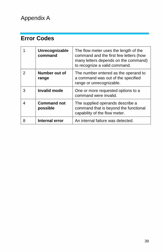
Error Codes
1 Unrecognizable
command
The flow meter uses the length of the
command and the first few letters (how
many letters depends on the command)
to recognize a valid command.
2 Number out of
range
The number entered as the operand to
a command was out of the specified
range or unrecognizable.
3 Invalid mode One or more requested options to a
command were invalid.
4 Command not
possible
The supplied operands describe a
command that is beyond the functional
capability of the flow meter.
8 Internal error An internal failure was detected.

40 Appendix A
(This page intentionally left blank)

41
Appendix B
Factory Default Parameters
Default factory parameter settings of the Series 5XXX flow meters.
Sample Rate ................................ 10 ms
Gas Calibration ............................ 0 = Air
Flow Units .................................... Standard
Display Update Rate .................... 500 ms
Humidity Compensation ............... On
Directional Sensor ........................ On
Triggers ........................................ Disabled

42 Appendix B
(This page intentionally left blank)


TSI Incorporated – Visit our website www.tsi.com for more information. USA Tel: +1 800 680 1220 UK Tel: +44 149 4 459200 France Tel: +33 1 41 19 21 99 Germany Tel: +49 241 523030
India Tel: +91 80 67877200 China Tel: +86 10 8219 7688 Singapore Tel: +65 6595 6388
P/N 6011697 Rev. B ©2019 TSI Incorporated Printed in U.S.A.
Related Documents