General-Purpose AC Servo MODEL MR-HP30KA/55KA4 CONVERTER UNIT INSTRUCTION MANUAL Large-Capacity Servo Manual Name Manual N0. Manual Name Manual N0. Manual Name Manual N0. Manual Name Manual N0. Manual Name Manual N0. Manual Name Manual N0. Manual Name Manual N0. Manual Name Manual N0. MR-J2S- A Servo Amplifier Instruction Manual Servo Motor Instruction Manual SH(NA)030006 SH(NA)3181 MR-J2S- B Servo Amplifier Instruction Manual Servo Motor Instruction Manual SH(NA)030007 SH(NA)3181 MR-H AN Servo Amplifier Instruction Manual Servo Motor Instruction Manual SH(NA)3190 SH(NA)3181 MR-H BN Servo Amplifier Instruction Manual Servo Motor Instruction Manual SH(NA)3192 SH(NA)3181 MR-J2S- A Servo Amplifier Instruction Manual Servo Motor Instruction Manual SH(NA)030006 SH(NA)3181 MR-J2S-30KA4 to 55KA4 MR-J2S- B Servo Amplifier Instruction Manual Servo Motor Instruction Manual SH(NA)030007 SH(NA)3181 MR-J2S-30KB4 to 55KB4 MR-H AN Servo Amplifier Instruction Manual Servo Motor Instruction Manual SH(NA)3190 SH(NA)3181 MR-H30KAN4 to 55KAN4 MR-H BN Servo Amplifier Instruction Manual Servo Motor Instruction Manual SH(NA)3192 SH(NA)3181 MR-H30KBN4 to 55KBN4 MR-J2S-30KA 37KA MR-J2S-30KB 37KB MR-H30KAN 37KAN MR-H30KBN 37KBN The corresponding manuals indicated below are required to use the Large-Capacity Servo. C

Welcome message from author
This document is posted to help you gain knowledge. Please leave a comment to let me know what you think about it! Share it to your friends and learn new things together.
Transcript

General-Purpose AC Servo
MODEL
MR-HP30KA/55KA4CONVERTER UNITINSTRUCTION MANUAL
Large-Capacity Servo
Manual Name Manual N0.
Manual Name Manual N0.
Manual Name Manual N0.
Manual Name Manual N0.
Manual Name Manual N0.
Manual Name Manual N0.
Manual Name Manual N0.
Manual Name Manual N0.
MR-J2S- A Servo Amplifier Instruction Manual
Servo Motor Instruction Manual
SH(NA)030006
SH(NA)3181
MR-J2S- B Servo Amplifier Instruction Manual
Servo Motor Instruction Manual
SH(NA)030007
SH(NA)3181
MR-H AN Servo Amplifier Instruction Manual
Servo Motor Instruction Manual
SH(NA)3190
SH(NA)3181
MR-H BN Servo Amplifier Instruction Manual
Servo Motor Instruction Manual
SH(NA)3192
SH(NA)3181
MR-J2S- A Servo Amplifier Instruction Manual
Servo Motor Instruction Manual
SH(NA)030006
SH(NA)3181
MR-J2S-30KA4 to 55KA4
MR-J2S- B Servo Amplifier Instruction Manual
Servo Motor Instruction Manual
SH(NA)030007
SH(NA)3181
MR-J2S-30KB4 to 55KB4
MR-H AN Servo Amplifier Instruction Manual
Servo Motor Instruction Manual
SH(NA)3190
SH(NA)3181
MR-H30KAN4 to 55KAN4
MR-H BN Servo Amplifier Instruction Manual
Servo Motor Instruction Manual
SH(NA)3192
SH(NA)3181
MR-H30KBN4 to 55KBN4
MR-J2S-30KA 37KA
MR-J2S-30KB 37KB
MR-H30KAN 37KAN
MR-H30KBN 37KBN
The corresponding manuals indicated below are required to use the Large-Capacity Servo.
C

A - 1
Safety Instructions (Always read these instructions before using the equipment.)
Do not attempt to install, operate, maintain or inspect the servo amplifier and servo motor until you have readthrough this Specifications and Instruction guide, Installation guide, Servo motor Instruction Manual andappended documents carefully and can use the equipment correctly. Do not use the servo amplifier and servomotor until you have a full knowledge of the equipment, safety information and instructions.In this Instruction Manual, the safety instruction levels are classified into "WARNING" and "CAUTION".
WARNING Indicates that incorrect handling may cause hazardous conditions,resulting in death or severe injury.
CAUTION Indicates that incorrect handling may cause hazardous conditions,resulting in medium or slight injury to personnel or may cause physicaldamage.
Note that the CAUTION level may lead to a serious consequence according to conditions. Please follow theinstructions of both levels because they are important to personnel safety.What must not be done and what must be done are indicated by the following diagrammatic symbols:
: Indicates what must not be done. For example, "No Fire" is indicated by .
: Indicates what must be done. For example, grounding is indicated by .
In this Specifications and Instruction Manual, instructions at a lower level than the above, instructions for otherfunctions, and so on are classified into "POINT".After reading this installation guide, always keep it accessible to the operator.

A - 2
1. To prevent electric shock, note the following:
CAUTIONBefore wiring or inspection, switch power off and wait for more than 20 minutes. Then, confirm the voltageis safe with voltage tester. Otherwise, you may get an electric shock.
Connect the Converter unit to ground.
Any person who is involved in wiring and inspection should be fully competent to do the work.
Do not attempt to wire the converter unit until they have been installed. Otherwise, you may get an electricshock.
Operate the switches with dry hand to prevent an electric shock.
The cables should not be damaged, stressed loaded, or pinched. Otherwise, you may get an electricshock.
During power-on or operation, do not open the front cover of the converter unit and the servo amplifier.You may get an electric shock.
Do not operate the Converter unit and the servo amplifier with the front cover removed. High-voltageterminals and charging area are exposed and you may get an electric shock.
Except for wiring or periodic inspection, do not remove the front cover even if the power is off.The Converter unit is charged and you may get an electric shock.
2. To prevent fire, note the following:
CAUTIONDo not install the converter unit and regenerative brake resistor on or near combustibles.Otherwise a fire may cause.
When the converter unit has become faulty, switch off the main converter unit power side.continuous flow of a large current may cause a fire.
When a regenerative brake resistor is used, use an alarm signal to switch main power off. Otherwise, aregenerative brake transistor fault or the like may overheat the regenerative brake resistor, causing a fire.
3. To prevent injury, note the follow
CAUTIONOnly the voltage specified in the Instruction Manual should be applied to each terminal, Otherwise, aburst, damage, etc. may occur.
Connect the terminals correctly to prevent a burst, damage, etc.
Ensure that polarity ( , ) is correct. Otherwise, a burst, damage, etc. may occur.
Take safety measures, e.g. provide covers, to prevent accidental contact of hands and parts (cables, etc.)with the servo amplifier heat sink, regenerative brake resistor, servo motor, etc. since they may be hotwhile power is on or for some time after power-off. Their temperatures may be high and you may get burntor a parts may damaged.
During operation, never touch the rotating parts of the servo motor. Doing so can cause injury.

A - 3
4. Additional instructionsThe following instructions should also be fully noted. Incorrect handling may cause a fault, injury, electricshock, etc.
(1) Transportation and installation
CAUTIONTransport the products correctly according to their masses.Stacking in excess of the specified number of products is not allowed.Do not climb or stand on servo equipment. Do not put heavy objects on equipment.The Converter unit must be installed in the specified direction.Leave specified clearances between the Converter unit and control enclosure walls or other equipment.Do not install or operate the Converter unit which has been damaged or has any parts missing.Provide adequate protection to prevent screws and other conductive matter, oil and other combustiblematter from entering the Converter unit.Do not drop or strike converter unit or servo motor. Isolate from all impact loads.Use the servo amplifier and servo motor under the following environmental conditions:
ConditionsEnvironment
Converter unit/Servo amplifier[ ] 0 to 55 (non-freezing)During
operation [ ] 32 to 131 (non-freezing)[ ] 20 to 65 (non-freezing)
Ambienttemperature
In storage[ ] 4 to 149 (non-freezing)
In operation 90%RH or less (non-condensing)Ambienthumidity In storage 90%RH or less (non-condensing)
Ambience Indoors (no direct sunlight) Free from corrosive gas, flammable gas, oil mist, dust anddirt
Altitude Max. 1000m (3280 ft) above sea level[m/s2] 5.9 or less
Vibration[ft/s2] 19.4 or less
When the equipment has been stored for an extended period of time, consult Mitsubishi.
(2) Wiring
CAUTIONWire the equipment correctly and securely.
The surge absorbing diode installed on the DC output signal relay must be wired in the specified direction.Otherwise, the emergency stop and other protective circuits may not operate.
VIN(24VDC)
RA
ControloutputsignalRA
VIN(24VDC)
Controloutputsignal
Servo AmplifierConverter unit
Servo AmplifierConverter unit

A - 4
(3) Test run adjustment
CAUTIONBefore operation, check the parameter settings. Improper settings may cause some machines to performunexpected operation.
The parameter settings must not be changed excessively. Operation will be insatiable.
(4) Usage
CAUTIONProvide an external emergency stop circuit to ensure that operation can be stopped and power switchedoff immediately.Any person who is involved in disassembly and repair should be fully competent to do the work.Do not modify the equipment.Use a noise filter, etc. to minimize the influence of electromagnetic interference, which may be caused byelectronic equipment used near the servo amplifier.
(5) Corrective actions
CAUTIONWhen any alarm has occurred, eliminate its cause, ensure safety, and deactivate the alarm beforerestarting operation.
(6) Maintenance, inspection and parts replacement
CAUTIONWith age, the electrolytic capacitor of the servo amplifier will deteriorate. To prevent a secondary accidentdue to a fault, it is recommended to replace the electrolytic capacitor every 10 years when used in generalenvironment.Please consult our sales representative.
(7) General instruction
To illustrate details, the equipment in the diagrams of this Specifications and Instruction Manual may havebeen drawn without covers and safety guards. When the equipment is operated, the covers and safetyguards must be installed as specified. Operation must be performed in accordance with this Specificationsand Instruction Manual.
About processing of waste When you discard servo amplifier, a battery (primary battery), and other option articles, please follow the law ofeach country (area).
A - 5
FOR MAXIMUM SAFETYThis product is not designed or manufactured to be used in equipment or systems in situations that canaffect or endanger human life.When considering this product for operation in special applications such as machinery or systems used inpassenger transportation, medical, aerospace, atomic power, electric power, or submarine repeatingapplications, please contact your nearest Mitsubishi sales representative.Although this product was manufactured under conditions of strict quality control, you are strongly advisedto install safety devices to forestall serious accidents when it is used in facilities where a breakdown in theproduct is likely to cause a serious accident.
EEP-ROM lifeThe number of write times to the EEP-ROM, which stores parameter settings, etc., is limited to 100,000. Ifthe total number of the following operations exceeds 100,000, the servo amplifier and/or converter unit mayfail when the EEP-ROM reaches the end of its useful life.
Write to the EEP-ROM due to parameter setting changesHome position setting in the absolute position detection systemWrite to the EEP-ROM due to device changes
A - 6
COMPLIANCE WITH EC DIRECTIVES1. WHAT ARE EC DIRECTIVES?The EC directives were issued to standardize the regulations of the EU countries and ensure smoothdistribution of safety-guaranteed products. In the EU countries, the machinery directive (effective inJanuary, 1995), EMC directive (effective in January, 1996) and low voltage directive (effective in January,1997) of the EC directives require that products to be sold should meet their fundamental safetyrequirements and carry the CE marks (CE marking). CE marking applies to machines and equipmentinto which servo amplifiers have been installed.
(1) EMC directiveThe EMC directive applies not to the servo units alone but to servo-incorporated machines andequipment. This requires the EMC filters to be used with the servo-incorporated machines andequipment to comply with the EMC directive. For specific EMC directive conforming methods, refer tothe EMC Installation Guidelines (IB(NA)67310).
(2) Low voltage directiveThe low voltage directive applies also to servo units alone. Hence, they are designed to comply withthe low voltage directive.This servo is certified by TUV, third-party assessment organization, to comply with the low voltagedirective.
(3) Machine directiveNot being machines, the servo amplifiers need not comply with this directive.
2. PRECAUTIONS FOR COMPLIANCE(1) Servo amplifiers and servo motors used
Use the converter unit, servo amplifiers and servo motors which comply with the standard model.
Converter unit :MR-HP30KA MR-HP55KA4Servo amplifier series :MR-J2S-30K MR-J2S-37K
MR-J2S-30K 4 to MR-J2S-55K 4Servo motor series :HA-LFS
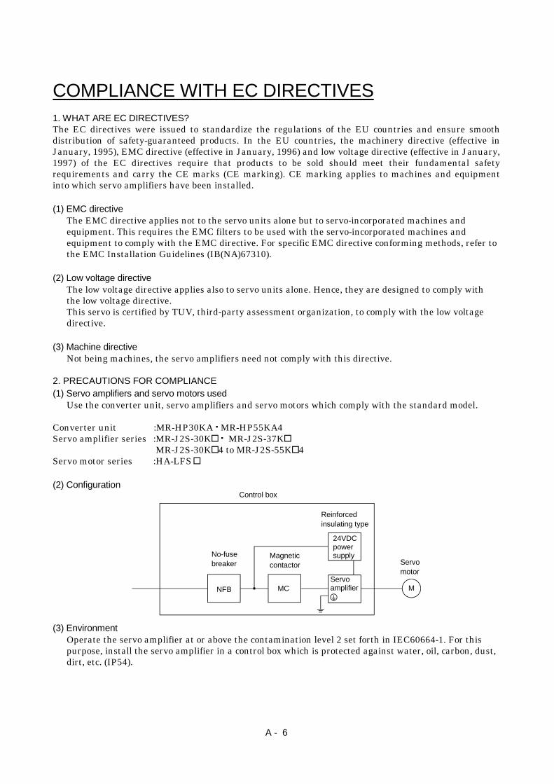
(2) Configuration
NFB MC M
No-fusebreaker
Magneticcontactor
Reinforcedinsulating type
24VDCpowersupply
Servoamplifier
Servomotor
Control box
(3) EnvironmentOperate the servo amplifier at or above the contamination level 2 set forth in IEC60664-1. For thispurpose, install the servo amplifier in a control box which is protected against water, oil, carbon, dust,dirt, etc. (IP54).
A - 7
(4) Power supply(a) Operate the servo amplifier to meet the requirements of the overvoltage category III set forth in
IEC60664-1.
(b) When supplying interface power from external, use a 24VDC power supply which has beeninsulation-reinforced in I/O.
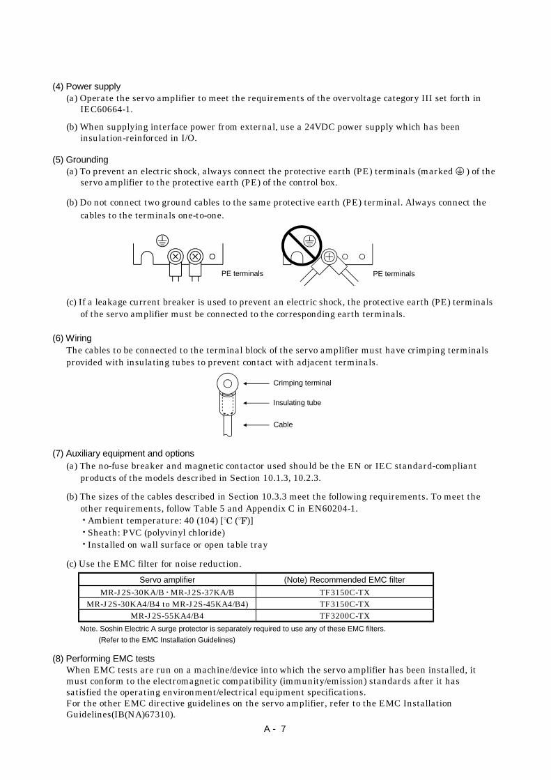
(5) Grounding(a) To prevent an electric shock, always connect the protective earth (PE) terminals (marked ) of the
servo amplifier to the protective earth (PE) of the control box.
(b) Do not connect two ground cables to the same protective earth (PE) terminal. Always connect thecables to the terminals one-to-one.
PE terminals PE terminals
(c) If a leakage current breaker is used to prevent an electric shock, the protective earth (PE) terminalsof the servo amplifier must be connected to the corresponding earth terminals.
(6) WiringThe cables to be connected to the terminal block of the servo amplifier must have crimping terminalsprovided with insulating tubes to prevent contact with adjacent terminals.
Crimping terminal
Insulating tube
Cable
(7) Auxiliary equipment and options(a) The no-fuse breaker and magnetic contactor used should be the EN or IEC standard-compliant
products of the models described in Section 10.1.3, 10.2.3.
(b) The sizes of the cables described in Section 10.3.3 meet the following requirements. To meet theother requirements, follow Table 5 and Appendix C in EN60204-1.
Ambient temperature: 40 (104) [ ( )]Sheath: PVC (polyvinyl chloride)Installed on wall surface or open table tray
(c) Use the EMC filter for noise reduction.Servo amplifier (Note) Recommended EMC filter
MR-J2S-30KA/B MR-J2S-37KA/B TF3150C-TXMR-J2S-30KA4/B4 to MR-J2S-45KA4/B4) TF3150C-TX
MR-J2S-55KA4/B4 TF3200C-TXNote. Soshin Electric A surge protector is separately required to use any of these EMC filters.
(Refer to the EMC Installation Guidelines)
(8) Performing EMC testsWhen EMC tests are run on a machine/device into which the servo amplifier has been installed, itmust conform to the electromagnetic compatibility (immunity/emission) standards after it hassatisfied the operating environment/electrical equipment specifications.For the other EMC directive guidelines on the servo amplifier, refer to the EMC InstallationGuidelines(IB(NA)67310).
A - 8
CONFORMANCE WITH UL/C-UL STANDARD(1) Servo amplifiers and servo motors used
Use the converter unit, servo amplifiers and servo motors which comply with the standard model.
Converter unit :MR-HP30KA MR-HP55KA4Servo amplifier series :MR-J2S-30K MR-J2S-37K
MR-J2S-30K 4 to MR-J2S-55K 4Servo motor series :HA-LFS
(2) InstallationInstall a fan of 100CFM (2.8 m3/min) air flow 4 [in] (10.16 [cm]) above the servo amplifier or providecooling of at least equivalent capability.
(3) Short circuit ratingThis servo amplifier conforms to the circuit whose peak current is limited to 5000A or less. Havingbeen subjected to the short-circuit tests of the UL in the alternating-current circuit, the servoamplifier conforms to the above circuit.
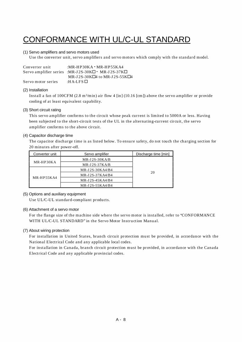
(4) Capacitor discharge timeThe capacitor discharge time is as listed below. To ensure safety, do not touch the charging section for20 minutes after power-off.
Converter unit Servo amplifier Discharge time [min]MR-J2S-30KA/BMR-HP30KA MR-J2S-37KA/B
MR-J2S-30KA4/B4MR-J2S-37KA4/B4MR-J2S-45KA4/B4MR-HP55KA4
MR-J2S-55KA4/B4
20
(5) Options and auxiliary equipmentUse UL/C-UL standard-compliant products.
(6) Attachment of a servo motorFor the flange size of the machine side where the servo motor is installed, refer to “CONFORMANCEWITH UL/C-UL STANDARD” in the Servo Motor Instruction Manual.
(7) About wiring protectionFor installation in United States, branch circuit protection must be provided, in accordance with theNational Electrical Code and any applicable local codes.For installation in Canada, branch circuit protection must be provided, in accordance with the CanadaElectrical Code and any applicable provincial codes.
A - 9
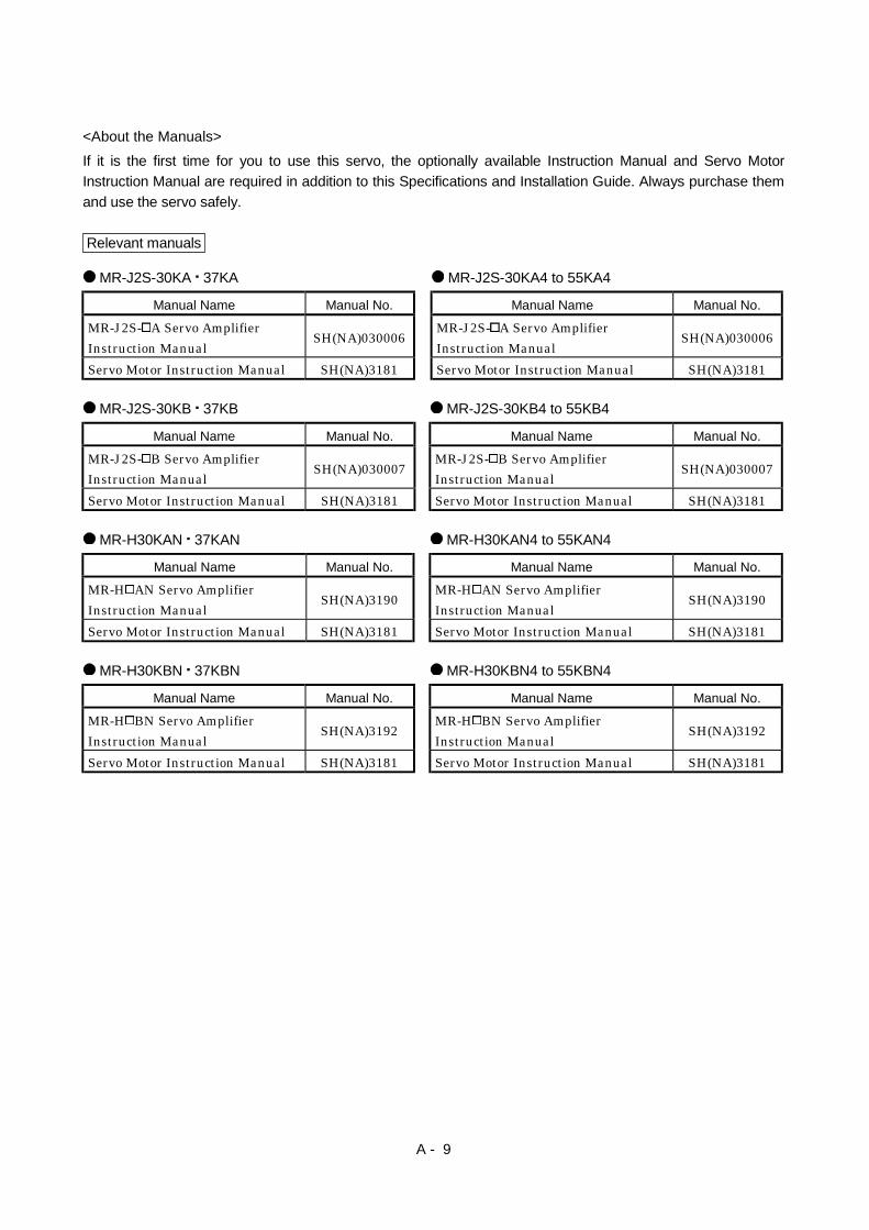
<About the Manuals>If it is the first time for you to use this servo, the optionally available Instruction Manual and Servo MotorInstruction Manual are required in addition to this Specifications and Installation Guide. Always purchase themand use the servo safely.
Relevant manuals
MR-J2S-30KA 37KA MR-J2S-30KA4 to 55KA4
Manual Name Manual No. Manual Name Manual No.
MR-J2S- A Servo AmplifierInstruction Manual
SH(NA)030006MR-J2S- A Servo AmplifierInstruction Manual
SH(NA)030006
Servo Motor Instruction Manual SH(NA)3181 Servo Motor Instruction Manual SH(NA)3181
MR-J2S-30KB 37KB MR-J2S-30KB4 to 55KB4
Manual Name Manual No. Manual Name Manual No.
MR-J2S- B Servo AmplifierInstruction Manual
SH(NA)030007MR-J2S- B Servo AmplifierInstruction Manual
SH(NA)030007
Servo Motor Instruction Manual SH(NA)3181 Servo Motor Instruction Manual SH(NA)3181
MR-H30KAN 37KAN MR-H30KAN4 to 55KAN4
Manual Name Manual No. Manual Name Manual No.
MR-H AN Servo AmplifierInstruction Manual
SH(NA)3190MR-H AN Servo AmplifierInstruction Manual
SH(NA)3190
Servo Motor Instruction Manual SH(NA)3181 Servo Motor Instruction Manual SH(NA)3181
MR-H30KBN 37KBN MR-H30KBN4 to 55KBN4
Manual Name Manual No. Manual Name Manual No.
MR-H BN Servo AmplifierInstruction Manual
SH(NA)3192MR-H BN Servo AmplifierInstruction Manual
SH(NA)3192
Servo Motor Instruction Manual SH(NA)3181 Servo Motor Instruction Manual SH(NA)3181

A - 10
MEMO

1
CONTENTS
1. FUNCTIONS AND STRUCTURE 1- 1 to 1-14
1.1 Precautions for use of the 200V class 37kW Servo amplifier.............................................................. 1- 11.2 Function block diagram .......................................................................................................................... 1- 21.3 Packing list............................................................................................................................................... 1- 41.4 Standard specification............................................................................................................................. 1- 5
1.4.1 Converter unit................................................................................................................................... 1- 51.4.2 Servo amplifier.................................................................................................................................. 1- 6
1.5 Model definition....................................................................................................................................... 1- 71.5.1 Rating plate ....................................................................................................................................... 1- 71.5.2 Model.................................................................................................................................................. 1- 7
1.6 Combinations of converter units, servo amplifiers and servo motors ................................................ 1- 81.7 Parts identification.................................................................................................................................. 1- 9
1.7.1 Converter unit (MR-HP-30KA/MR-HP55KA4) ............................................................................. 1- 91.7.2 Servo amplifier................................................................................................................................. 1-10
1.8 Servo system with auxiliary equipment............................................................................................... 1-14
2. INSTALLATION 2- 1 to 2- 2
2.1 Environmental conditions....................................................................................................................... 2- 12.2 Installation direction and clearances .................................................................................................... 2- 2
3. SIGNALS AND WIRING 3- 1 to 3-20
3.1 I/O Signals of Converter Unit (MR-HP30KA/MR-HP55KA4)............................................................. 3- 23.2 Connectors and signal layouts of the servo amplifiers ........................................................................ 3- 4
3.2.1 MELSERVO-J2-Super series .......................................................................................................... 3- 43.2.2 MELSERVO-H series....................................................................................................................... 3- 6
3.3 Power line circuit..................................................................................................................................... 3- 83.3.1 Connection example.......................................................................................................................... 3- 93.3.2 Terminal ........................................................................................................................................... 3-173.3.3 How to use the connection bars...................................................................................................... 3-173.3.4 Power-on sequence........................................................................................................................... 3-18
3.4 Servo motor side details......................................................................................................................... 3-193.5 Grounding................................................................................................................................................ 3-20
4. DISPLAY SECTION AND OPERATION SECTION OF THE CONVERTER UNIT 4- 1 to 4- 6
4.1 Display flowchart..................................................................................................................................... 4- 14.2 Status display mode ................................................................................................................................ 4- 2
4.2.1 Display examples .............................................................................................................................. 4- 24.2.2 Status display list ............................................................................................................................. 4- 2
4.3 Diagnostic mode....................................................................................................................................... 4- 34.3.1 Diagnostic list.................................................................................................................................... 4- 34.3.2 External output signal indication ................................................................................................... 4- 3

2
4.3.3 Output signal forced output............................................................................................................. 4- 44.4 Alarm mode.............................................................................................................................................. 4- 54.5 Parameter mode ...................................................................................................................................... 4- 6
5. PARAMETER 5- 1 to 5- 6
5.1 Converter unit.......................................................................................................................................... 5- 15.2 Servo amplifier......................................................................................................................................... 5- 2
5.2.1 MELSERVO-J2-Super series .......................................................................................................... 5- 25.2.2 MELSERVO-H series....................................................................................................................... 5- 4
6. INSPECTION 6- 1 to 6- 2
6.1 Inspection ................................................................................................................................................. 6- 16.2 Life ............................................................................................................................................................ 6- 1
7. TROUBLESHOOTING 7- 1 to 7- 6
7.1 Converter unit.......................................................................................................................................... 7- 17.1.1 Alarms and warning list .................................................................................................................. 7- 17.1.2 Remedies for alarms......................................................................................................................... 7- 17.1.3 Remedies for warnings..................................................................................................................... 7- 37.1.4. Clearing the alarm history ............................................................................................................. 7- 3
7.2 Servo amplifier......................................................................................................................................... 7- 47.2.1 Alarm codes ....................................................................................................................................... 7- 47.2.2 Alarm corrective actions .................................................................................................................. 7- 5
8. OUTLINE DIMENSIONAL DRAWINGS 8- 1 to 8- 8
8.1 Converter unit (MR-HP30KA/MR-HP55KA4)...................................................................................... 8- 18.2 Servo amplifier......................................................................................................................................... 8- 2
8.2.1 MELSERVO-J2-Super series .......................................................................................................... 8- 28.2.2 MELSERVO-H series....................................................................................................................... 8- 3
8.3 Connector.................................................................................................................................................. 8- 5
9. CHARACTERISTICS 9- 1 to 9- 4
9.1 Overload protection characteristics ....................................................................................................... 9- 19.2 Power supply equipment capacity and generated loss ........................................................................ 9- 29.3 Dynamic brake characteristics............................................................................................................... 9- 4
10. OPTIONS AND AUXILIARY EQUIPMENT 10- 1 to 10-28
10.1 200V class dedicated options.............................................................................................................. 10- 110.1.1 Regenerative brake option (200V class) ..................................................................................... 10- 110.1.2 External dynamic brake (200V class)......................................................................................... 10- 510.1.3 No-fuse breakers, magnetic contactors (200V class)................................................................. 10- 910.1.4 Power factor improving DC reactor (200V class)....................................................................... 10- 910.1.5 Radio noise filter (200V class) ....................................................................................................10-10
3
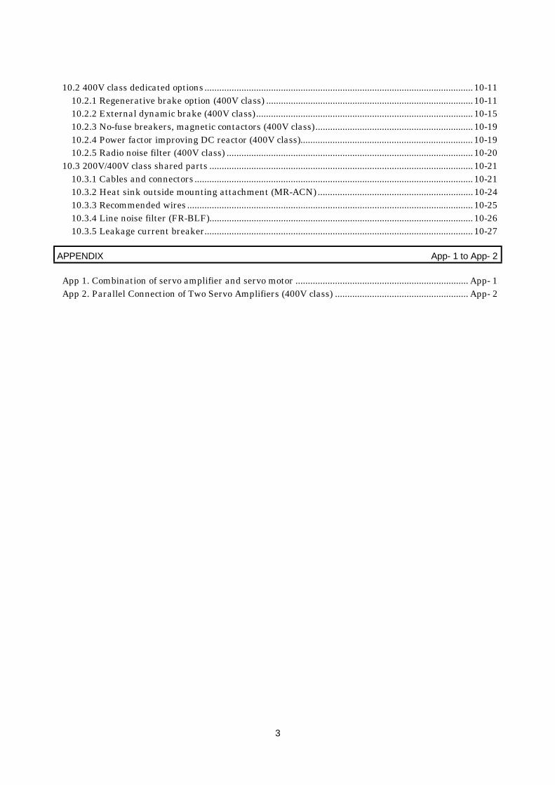
10.2 400V class dedicated options.............................................................................................................10-1110.2.1 Regenerative brake option (400V class) ....................................................................................10-1110.2.2 External dynamic brake (400V class)........................................................................................10-1510.2.3 No-fuse breakers, magnetic contactors (400V class)................................................................10-1910.2.4 Power factor improving DC reactor (400V class)......................................................................10-1910.2.5 Radio noise filter (400V class) ....................................................................................................10-20
10.3 200V/400V class shared parts ...........................................................................................................10-2110.3.1 Cables and connectors.................................................................................................................10-2110.3.2 Heat sink outside mounting attachment (MR-ACN) ...............................................................10-2410.3.3 Recommended wires....................................................................................................................10-2510.3.4 Line noise filter (FR-BLF)...........................................................................................................10-2610.3.5 Leakage current breaker.............................................................................................................10-27
APPENDIX App- 1 to App- 2
App 1. Combination of servo amplifier and servo motor ...................................................................... App- 1App 2. Parallel Connection of Two Servo Amplifiers (400V class) ...................................................... App- 2

4
MEMO

1 - 1
1. FUNCTIONS AND STRUCTURE
1. FUNCTIONS AND STRUCTURE
1.1 Precautions for use of the 200V class 37kW Servo amplifier
POINT Please consult us when using the 200V class 37kW servo amplifier.
The 200V class 37kW servo amplifier can be used with the machine whose driving mode output is 30kWor less. The load torque in the driving mode can be used up to 81% of the rated torque.
0
0
tpsa tc tpsd
Tma
Td
TL
Time
N [r/
min
]Se
rvo
mot
or s
peed
Time
Serv
o m
otor
torq
ue Driving
TaDrivingTLH Driving
tf (1 cycle)
Tmd Regenerationt
Trmstf
Tma2 tpsa TLH2tcTL2 t
Trms: Servo motor shaft-equivalent continuous effective load torque indriving mode [N m]
Tma: Servo motor torque necessary for acceleration [N m]tpsa: Acceleration time [s]tpsd: Deceleration time [s]TL: Servo motor shaft-equivalent load torque [N m]tc: Time at constant speed of servo motor in one cycle [s]TLH: Torque applied at servo motor stop [N m]T : Stop time [s]
Tmd (regeneration) is not added. Always make the Trms value not more than 75% of the rated torque.
1 - 2
1. FUNCTIONS AND STRUCTURE
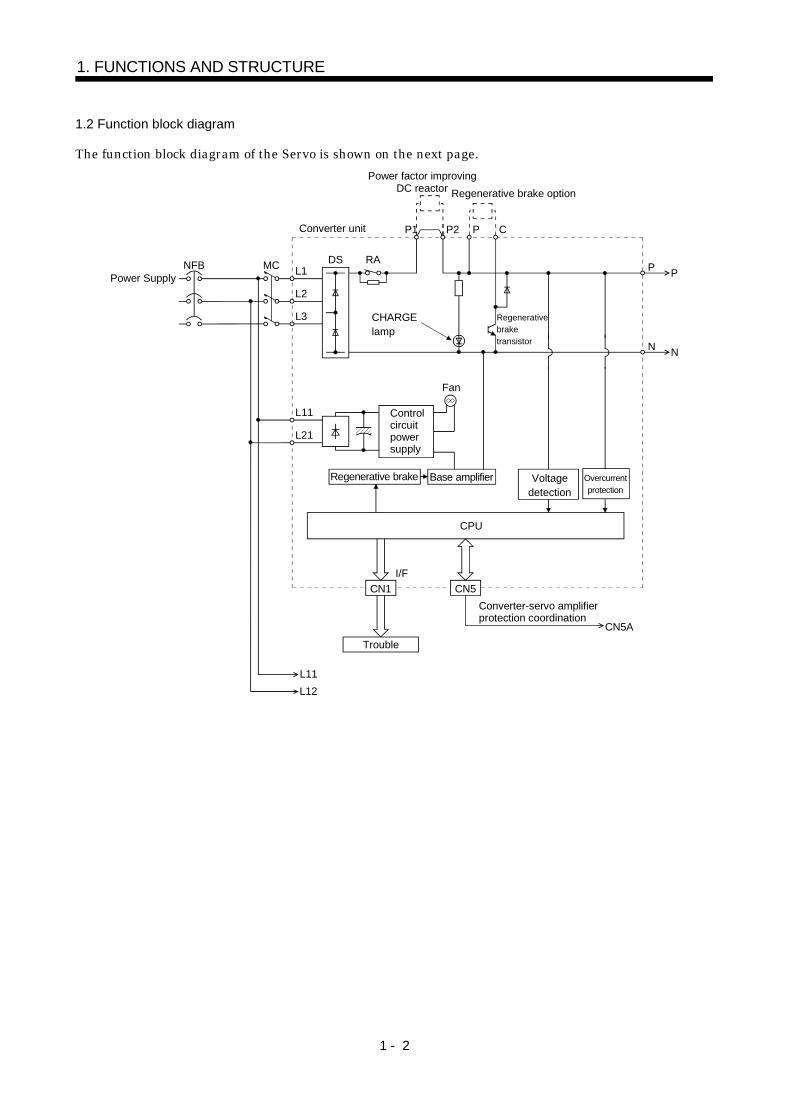
1.2 Function block diagram
The function block diagram of the Servo is shown on the next page.
Power SupplyNFB MC L1
L2
L3
DS RA
L11
L21
Controlcircuitpower supply
Fan
Regenerative brake Base amplifier Voltagedetection
Overcurrentprotection
I/F
P1
CHARGElamp
P2 P
CN1 CN5
Converter unit C
Regenerative brake option
P
N
CPU
L11L12
Converter-servo amplifier protection coordination
CN5A
P
N
Trouble
Regenerativebraketransistor
Power factor improvingDC reactor

1 - 3
1. FUNCTIONS AND STRUCTURE
CN1 CN4 CN3
D/A
Parameter unit
Analog monitor 2CH
P
BUBV
U U
V
W
V
WM
Encoder
CN
2
Currentdetector
N
CHARGElamp
L11
L12
Fan
Servo amplifier (Note 1)
CN
5 MR-BAT
Optional battery(for absolute positiondetection system)A/D
I/F
Analog2ch
Servo motor
Model positioncontrol
Pulse input
Model position Model speed
Virtualmotor
Virtualencoder
BW
OHS1 OHS2
P
N
L11
L12
CN
5AC
N5B
MR-A-TM termination connector(Option)
CN5A
Thermal relay
Fan
(Note 1)
(Note 1)
RS-232C
Overcurrentprotection
Base amplifier
Model speedcontrol
Actual positioncontrol
Current controlActual speedcontrol
Model torque
CN1 CN11 CN12
D I/O control Servo on Start Failure,etc
Currentdetection
Controlcircuitpower supply
Power SupplyNFB(Note2)
Note 1. For MR-H-AN2. Refer to Section 3.4 for the power supply specifications of the servo motor cooling fan.

1 - 4
1. FUNCTIONS AND STRUCTURE
1.3 Packing list
Unpack the product and check the rating plate to see if the converter unit, servo amplifier and servomotor are as you ordered.(1) Converter unit
Model Converter unit [units] To Use The AC Servo Safely [manuals]
MR-HP30KA 1 1MR-HP55KA4 1 1
(2) Servo AmplifierPOINTThe servo amplifier is not packed with a regenerative brake resistor.Always purchase the regenerative brake option. (Refer to Sections 10.1.1,10.2.1.)
ModelServo Amplifier
[units]
ConnectionConductor
[pcs.]
ConversionConnectorMR-HCN2
To Use The AC ServoSafely
[manuals]MR-J2S-30KA MR-J2S-37KA
MR-J2S-30KB MR-J2S-37KB1 2 1 1
MR-H30KAN MR-H37KANMR-H30KBN MR-H37KBN
1 2 1
MR-J2S-30KA4 toMR-J2S-55KA4
MR-J2S-30KB4 toMR-J2S-55KB4
1 2 1 1
MR-H30KAN4 to MR-H55KAN4MR-H30KBN4 to MR-H55KBN4
1 2 1
(3) Servo motorModel Servo motor [units] To Use The AC Servo Safely [manuals]
HA-LFS30K2 HA-LFS37K2HA-LF30K2 HA-LF37K2 1 1
HA-LFS30K24 to HA-LFS55K24HA-LF30K24 to HA-LF55K24 1 1
1 - 5
1. FUNCTIONS AND STRUCTURE
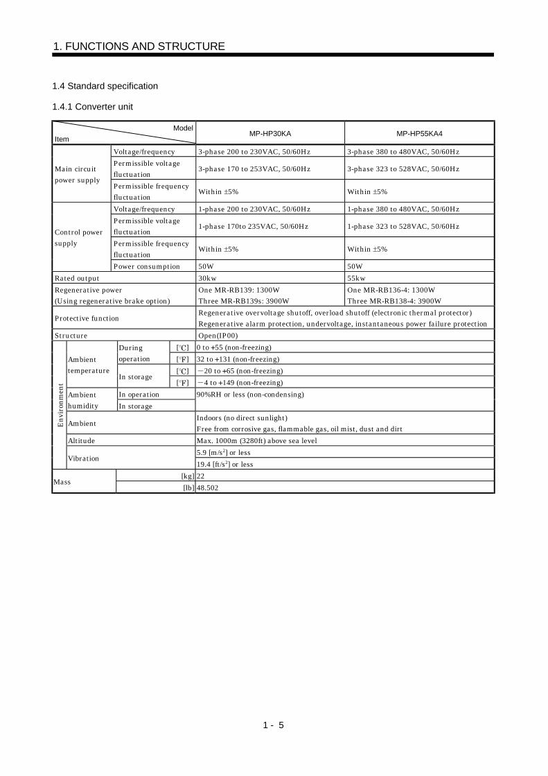
1.4 Standard specification
1.4.1 Converter unit
ModelItem
MP-HP30KA MP-HP55KA4
Voltage/frequency 3-phase 200 to 230VAC, 50/60Hz 3-phase 380 to 480VAC, 50/60HzPermissible voltagefluctuation 3-phase 170 to 253VAC, 50/60Hz 3-phase 323 to 528VAC, 50/60HzMain circuit
power supplyPermissible frequencyfluctuation Within 5% Within 5%
Voltage/frequency 1-phase 200 to 230VAC, 50/60Hz 1-phase 380 to 480VAC, 50/60HzPermissible voltagefluctuation 1-phase 170to 235VAC, 50/60Hz 1-phase 323 to 528VAC, 50/60Hz
Permissible frequencyfluctuation Within 5% Within 5%
Control powersupply
Power consumption 50W 50WRated output 30kw 55kwRegenerative power(Using regenerative brake option)
One MR-RB139: 1300WThree MR-RB139s: 3900W
One MR-RB136-4: 1300WThree MR-RB138-4: 3900W
Protective function Regenerative overvoltage shutoff, overload shutoff (electronic thermal protector)Regenerative alarm protection, undervoltage, instantaneous power failure protection
Structure Open(IP00)[ ] 0 to 55 (non-freezing)During
operation [ ] 32 to 131 (non-freezing)[ ] 20 to 65 (non-freezing)
Ambienttemperature
In storage[ ] 4 to 149 (non-freezing)
In operationAmbienthumidity In storage
90%RH or less (non-condensing)
Ambient Indoors (no direct sunlight)Free from corrosive gas, flammable gas, oil mist, dust and dirt
Altitude Max. 1000m (3280ft) above sea level5.9 [m/s2] or less
Envi
ronm
ent
Vibration19.4 [ft/s2] or less
[kg] 22Mass
[lb] 48.502

1 - 6
1. FUNCTIONS AND STRUCTURE
1.4.2 Servo amplifier
(1) 200V classServo amplifier
Item MR-J2S-30KA/B MR-J2S-37KA/B MR-H30KAN/BN MR-H37KAN/BN
Voltage/frequency Single-phase 200 to 230VAC, 50/60HzPermissible voltagefluctuation Single-phase 170 to 253VAC, 50/60Hz
Permissible frequencyfluctuation Within 5%
Control powersupply
Power consumption 50WMain circuit power supply The main circuit power of the servo amplifier is supplied by the converter unit.Control system Sine-wave PWM control, current control systemStructure Open (IP00)
[ ] 0 to 55 (non-freezing)Duringoperation [ ] 32 to 131 (non-freezing)
[ ] 20 to 65 (non-freezing)Ambienttemperature
In storage[ ] 4 to 149 (non-freezing)
In operationAmbienthumidity In storage
90%RH or less (non-condensing)
Ambient Indoors (no direct sunlight)Free from corrosive gas, flammable gas, oil mist, dust and dirt
Altitude Max. 1000m (3280ft) above sea level5.9 [m/s2] or less
Envi
ronm
ent
Vibration19.4 [ft/s2] or less
[kg] 47Mass
[lb] 103.617Function Refer to the corresponding Servo Amplifier Instruction Manual of 22kW or less.
(2) 400V classServo amplifier
ItemMR-J2S-30KA4/B4MR-H30KAN4/BN4
MR-J2S-37KA4/B4MR-H37KAN4/BN4
MR-J2S-45KA4/B4MR-H45KAN4/BN4
MR-J2S-55KA4/B4MR-H55KAN4/BN4
Voltage/frequency Single-phase 380 to 480VAC, 50/60HzPermissible voltagefluctuation Single-phase 323 to 528VAC, 50/60Hz
Permissible frequencyfluctuation Within 5%
Control powersupply
Power consumption 50WMain circuit power supply The main circuit power of the servo amplifier is supplied by the converter unit.System Sine-wave PWM control, current control systemStructure Open (IP00)
[ ] 0 to 55 (non-freezing)Duringoperation [ ] 32 to 131 (non-freezing)
[ ] 20 to 65 (non-freezing)Ambienttemperature
In storage[ ] 4 to 149 (non-freezing)
In operation 90%RH or less (non-condensing)Ambienthumidity In storage
Ambient Indoors (no direct sunlight)Free from corrosive gas, flammable gas, oil mist, dust and dirt
Altitude Max. 1000m (3280ft) above sea level5.9 [m/s2] or less
Envi
ronm
ent
Vibration19.4 [ft/s2] or less
[kg] 36 47 47 47Mass
[lb] 79.37 103.617 103.617 103.617Function Refer to the corresponding Servo Amplifier Instruction Manual of 22kW or less.

1 - 7
1. FUNCTIONS AND STRUCTURE
1.5 Model definition
1.5.1 Rating plate
POWER
MITSUBISHI AC SERVO
MR-HP30KA
OUTPUT :
AC SERVO
SERIAL : A******
30kWPOWER :AC200V-230V 50/60HzINPUT :
PASSED
MADE IN JAPANMITSUBISHI ELECTRIC CORPORATION
MODELModel Capacity
Applicable power supply
Rated output current
Serial number
MR-HP30KA SERIALA******
For side For front
TC300A156G54
1.5.2 Model
(1) Converter unit
3055
MR - HP A
Series namePower supplySymbol Power SupplyNone Three-phase 200 to 230VAC
Three-phase 400 to 480VAC4
Rated output
SymbolRated Output [kW]
200V class 400V class30K55K
(2) Servo Amplifier(a) MELSERVO-J2-Super series
MR - J2S -
Series name Symbol Power SupplyNone 200V class
400V class4
SymbolRated Output [kW]
200V class 400V class30K37K
General-purpose interfaceSSCNET-compatible
Symbol Power SupplyAB
3037
45K55K
30374555
Power supply
Rated output
Servo amplifier type

1 - 8
1. FUNCTIONS AND STRUCTURE
(b) MELSERVO-H seriesMR - H
Series name Symbol Power SupplyNone 200V class
400V class4
SymbolRated Output [kW]
200V class 400V class30K37K
General-purpose interfaceSSCNET-compatible
Symbol Power SupplyAB
3037
45K55K
30374555
Power supply
Rated output
Servo amplifier type
1.6 Combinations of converter units, servo amplifiers and servo motors
The following tables indicate the combinations of the converter units, servo amplifiers and servo motors.These servo motors may not be connected depending on the production time of the servo amplifier. Pleaserefer to app1.
(1) 200V classServo motor
HA-LFS HA-LFConverter unit Servo Amplifier
1000r/min 1500r/min 2000r/min(Note)
1000r/min(Note)
1500r/min2000r/min
MR-J2S-30KA/B 30K1 30K1M 30K2
MR-J2S-37KA/B (Note)37K1
(Note)37K1M 37K2
MR-H30KAN/BN 30K1 30K1M 30K2MR-HP30KA
MR-H37KAN/BN 37K1 37K1M 37K2
(2) 400V classServo motor
HA-LFS HA-LFConverter unit Servo Amplifier
1000r/min 1500r/min 2000r/min(Note)
1000r/min(Note)
1500r/min2000r/min
MR-J2S-30KA4/B4(Note)25K1430K14
30K1M4 30K24
MR-J2S-37KA4/B4 (Note)37K14 37K1M4 37K24
MR-J2S-45KA4/B4 45K1M4 45K24MR-J2S-55KA4/B4 50K1M4 55K24MR-H30KAN4/BN4 30K14 30K1M4 30K24MR-H37KAN4/BN4 37K14 37K1M4 37K24MR-H45KAN4/BN4 45K1M4 45K24
MR-HP55KA4
MR-H55KAN4/BN4 50K1M4 55K24Note. Consult us since the servo amplifier to be used with any of these servo motors is optional.
1 - 9
1. FUNCTIONS AND STRUCTURE
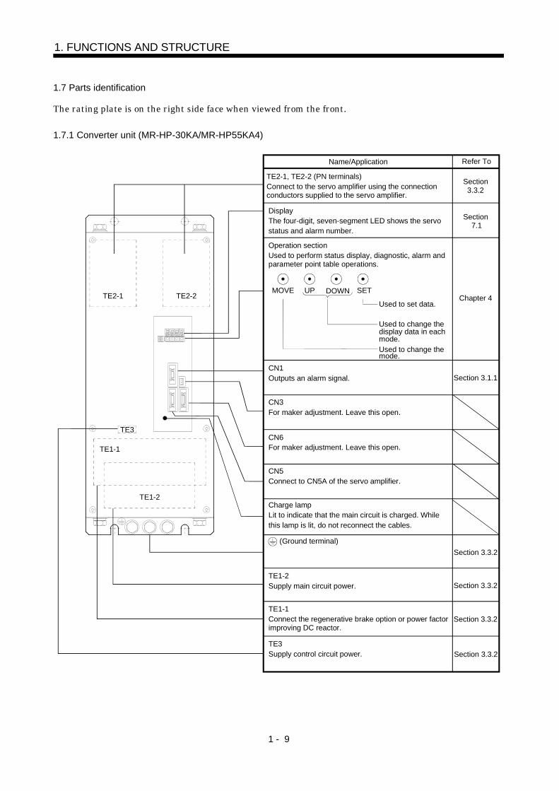
1.7 Parts identification
The rating plate is on the right side face when viewed from the front.
1.7.1 Converter unit (MR-HP-30KA/MR-HP55KA4)
Refer To
TE2-1, TE2-2 (PN terminals)Connect to the servo amplifier using the connection conductors supplied to the servo amplifier.
DisplayThe four-digit, seven-segment LED shows the servostatus and alarm number.
Section 7.1
Operation sectionUsed to perform status display, diagnostic, alarm and parameter point table operations.
MOVE UP DOWN SET
Used to set data.
Used to change the display data in each mode.Used to change the mode.
Charge lampLit to indicate that the main circuit is charged. Whilethis lamp is lit, do not reconnect the cables.
CN1Outputs an alarm signal.
CN3For maker adjustment. Leave this open.
CN6For maker adjustment. Leave this open.
CN5Connect to CN5A of the servo amplifier.
(Ground terminal)
TE1-2Supply main circuit power.
Section3.3.2
TE1-1Connect the regenerative brake option or power factor improving DC reactor.
TE3Supply control circuit power.
Section 3.1.1
Name/Application
Section 3.3.2
Chapter 4
Section 3.3.2
Section 3.3.2
Section 3.3.2
TE2-1 TE2-2
TE1-1
TE1-2
TE3

1 - 10
1. FUNCTIONS AND STRUCTURE
1.7.2 Servo amplifier
(1) MR-J2S- A/A4
Section 3.3.2
(Ground terminal)
CN5A
CN5BFron
t
View aTE3 (Control circuit terminal)Supply control circuit power.TE1Connect to U, V, W of the servo motor.
Battery holderContains the battery for absolute position data backup.
DisplayThe 5-digit, seven-segment LED shows the servo status and alarm number.Switch window CON1 : Connector for connection of the battery for absolute position detection
CN4 (Analog monitor output connector)Used to output an analog monitor signal.
CN3 (Communication connector)Used for connection with the personal computer.
CN1A/CN1B (I/O signal connector)Used to connect digital I/O signals.
CN2 (Encoder connector)Connector for connection of the servo motor encoder.
Refer ToName/Application
Connect to the PN terminals of the converter unit using the connection conductors supplied.
TE2-1, TE2-2 (PN terminals)
CN5A, CN5B (Converter unit connectors) CN5A: Connect to CN5 of the converter unit. CN5B: Connect the termination connector (MR-A-TM).
Section 3.3.1
Section 3.3.2
Section 3.3.2
Section 3.3.2
Section 3.2.1(1)
ManualInstruction Servo Amplifier
ManualInstruction Servo Amplifier
ManualInstruction Servo Amplifier
ManualInstruction Servo Amplifier
ManualInstruction Servo Amplifier
Section 3.2.1(1)
ManualInstruction Servo Amplifier
CON2 (Connector for manufacturer adjustment)Keep it open.
CN2CN5ACN5B
TE3
TE1
CON2
CN1B
CN1A
CN3
CN4
TE2-2TE2-1
Charge lamp
MODE UP DOWN SET
Operation sectionUsed to perform status display, diagnostic, alarm andparameter setting operations.
Used to set data.Used to change thedisplay or data in eachmode.Used to change themode.
1 - 11
1. FUNCTIONS AND STRUCTURE
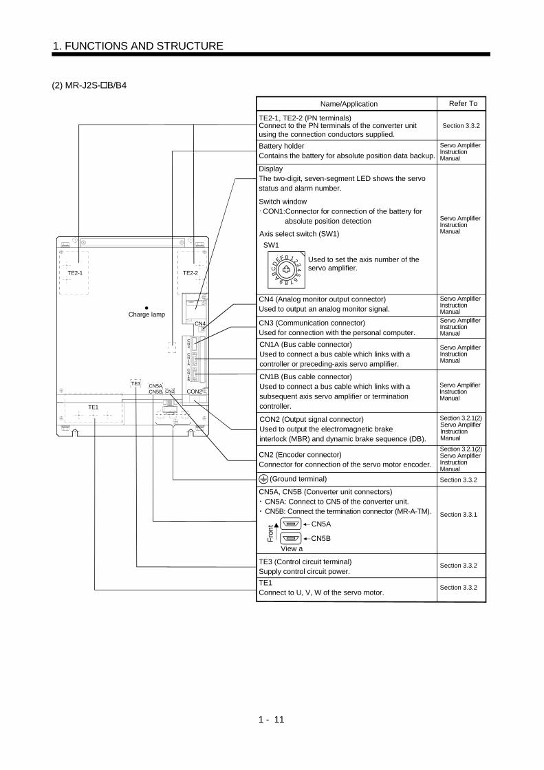
(2) MR-J2S- B/B4
Battery holderContains the battery for absolute position data backup.
DisplayThe two-digit, seven-segment LED shows the servostatus and alarm number.
Switch window CON1: Connector for connection of the battery for absolute position detection
CN4 (Analog monitor output connector)Used to output an analog monitor signal.
CN3 (Communication connector)Used for connection with the personal computer.CN1A (Bus cable connector)Used to connect a bus cable which links with a controller or preceding-axis servo amplifier.
CN1B (Bus cable connector)Used to connect a bus cable which links with a subsequent axis servo amplifier or termination controller.
Section 3.3.2Connect to the PN terminals of the converter unit using the connection conductors supplied.
TE2-1, TE2-2 (PN terminals)
Refer ToName/Application
CN2 (Encoder connector)Connector for connection of the servo motor encoder.
(Ground terminal)
CN5A
CN5BFron
t
View a
CN5A, CN5B (Converter unit connectors) CN5A: Connect to CN5 of the converter unit. CN5B: Connect the termination connector (MR-A-TM). Section 3.3.1
TE3 (Control circuit terminal)Supply control circuit power.
Section 3.3.2
TE1Connect to U, V, W of the servo motor.
Section 3.3.2
Section 3.3.2
Section 3.2.1(2)
ManualInstruction Servo Amplifier
ManualInstruction Servo Amplifier
ManualInstruction Servo Amplifier
ManualInstruction Servo Amplifier
ManualInstruction Servo Amplifier
ManualInstruction Servo Amplifier
Section 3.2.1(2)
ManualInstruction Servo Amplifier
ManualInstruction Servo Amplifier
CON2 (Output signal connector)Used to output the electromagnetic brake interlock (MBR) and dynamic brake sequence (DB).
CN2CN5ACN5B
TE3
TE1
CON2
CN1B
CN1A
CN3
CN4
TE2-2TE2-1
Charge lamp
Axis select switch (SW1)
1
CB A 9 8 76
54
320FE
D
SW1
Used to set the axis number of the servo amplifier.
1 - 12
1. FUNCTIONS AND STRUCTURE
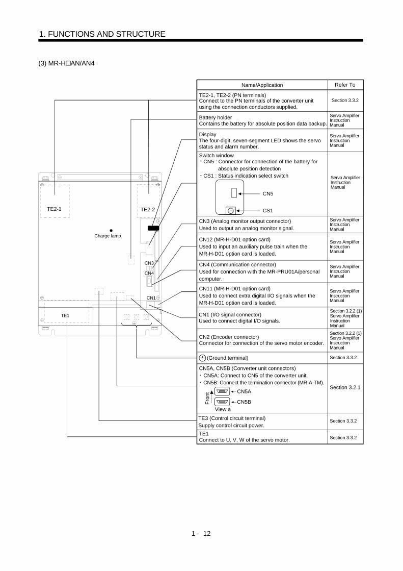
(3) MR-H AN/AN4
CN5
CS1
Section 3.3.2
(Ground terminal)
CN5A
CN5BFron
t
View aTE3 (Control circuit terminal)Supply control circuit power.TE1Connect to U, V, W of the servo motor.
Charge lamp
CN1
CN4
CN3
TE2-2
TE1
TE2-1
Battery holderContains the battery for absolute position data backup.
DisplayThe four-digit, seven-segment LED shows the servo status and alarm number.Switch window CN5 : Connector for connection of the battery for absolute position detection CS1 : Status indication select switch
CN3 (Analog monitor output connector)Used to output an analog monitor signal.
CN12 (MR-H-D01 option card)Used to input an auxiliary pulse train when the MR-H-D01 option card is loaded.
CN4 (Communication connector)Used for connection with the MR-PRU01A/personal computer.
CN11 (MR-H-D01 option card)Used to connect extra digital I/O signals when the MR-H-D01 option card is loaded.
CN1 (I/O signal connector)Used to connect digital I/O signals.
CN2 (Encoder connector)Connector for connection of the servo motor encoder.
Refer ToName/Application
Connect to the PN terminals of the converter unit using the connection conductors supplied.
TE2-1, TE2-2 (PN terminals)
CN5A, CN5B (Converter unit connectors) CN5A: Connect to CN5 of the converter unit. CN5B: Connect the termination connector (MR-A-TM).
Section 3.2.1
Section 3.3.2
Section 3.3.2
Section 3.3.2
Section 3.2.2 (1)
ManualInstruction Servo Amplifier
ManualInstruction Servo Amplifier
ManualInstruction Servo Amplifier
ManualInstruction Servo Amplifier
ManualInstruction Servo Amplifier
ManualInstruction Servo Amplifier
ManualInstruction Servo Amplifier
ManualInstruction Servo Amplifier
Section 3.2.2 (1)
ManualInstruction Servo Amplifier
1 - 13
1. FUNCTIONS AND STRUCTURE
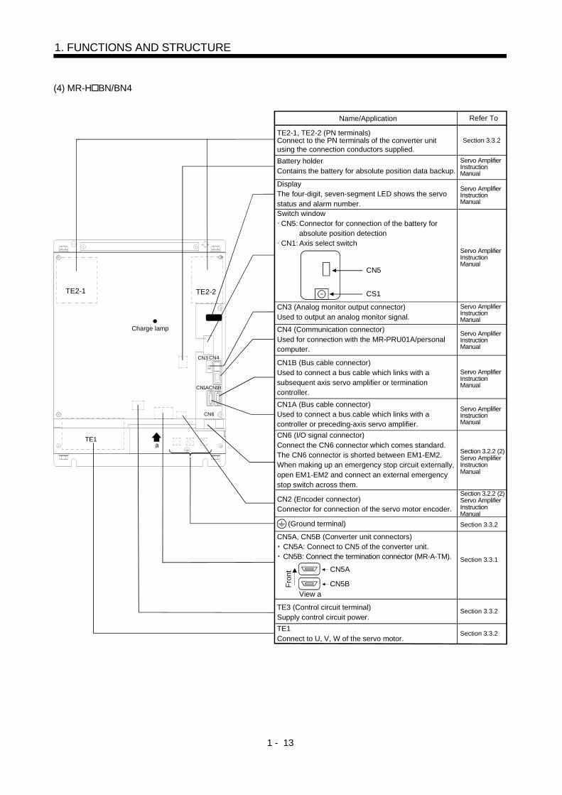
(4) MR-H BN/BN4
Battery holderContains the battery for absolute position data backup.
DisplayThe four-digit, seven-segment LED shows the servostatus and alarm number.Switch window CN5: Connector for connection of the battery for absolute position detection CN1: Axis select switch
CN3 (Analog monitor output connector)Used to output an analog monitor signal.CN4 (Communication connector)Used for connection with the MR-PRU01A/personal computer.
CN6 (I/O signal connector)Connect the CN6 connector which comes standard.The CN6 connector is shorted between EM1-EM2.When making up an emergency stop circuit externally, open EM1-EM2 and connect an external emergency stop switch across them.
CN1A (Bus cable connector)Used to connect a bus cable which links with a controller or preceding-axis servo amplifier.
CN1B (Bus cable connector)Used to connect a bus cable which links with a subsequent axis servo amplifier or termination controller.
CN1BCN1A
CN5
CS1
Charge lamp
CN6
TE2-2
TE1
TE2-1
a
CN3 CN4
CN2 (Encoder connector)Connector for connection of the servo motor encoder.
Section 3.3.2Connect to the PN terminals of the converter unit using the connection conductors supplied.
TE2-1, TE2-2 (PN terminals)
Refer ToName/Application
(Ground terminal)
CN5A
CN5BFron
t
View a
CN5A, CN5B (Converter unit connectors) CN5A: Connect to CN5 of the converter unit. CN5B: Connect the termination connector (MR-A-TM). Section 3.3.1
TE3 (Control circuit terminal)Supply control circuit power.
Section 3.3.2
TE1Connect to U, V, W of the servo motor.
Section 3.3.2
Section 3.3.2
Section 3.2.2 (2)
ManualInstruction Servo Amplifier
ManualInstruction Servo Amplifier
ManualInstruction Servo Amplifier
ManualInstruction Servo Amplifier
ManualInstruction Servo Amplifier
ManualInstruction Servo Amplifier
ManualInstruction Servo Amplifier
Section 3.2.2 (2)
ManualInstruction Servo Amplifier
ManualInstruction Servo Amplifier

1 - 14
1. FUNCTIONS AND STRUCTURE
1.8 Servo system with auxiliary equipment
Converter unitServo amplifier
3-phase, 200 to 230VAC
No-fuse breaker(NFB)
Magnetic contactor(MC)
Line noise filter(FR-BLF)
R S T
Servo motorHA-LF series
R1
S1 C
P
BU BV BW U
P
N
L1L2L3
P1
W
P
N
V W E
V
CN1
P2
P C
CN1CN5
L21
L11
U
CN5AL21
L11
CN2
Encoder cable
(Note2)Parameter unit cable
or communication cable
Servo Configurationsoftware
Personalcomputer
Parameter unit
or
CN4
(MR-HSCBL M)
The parameter unit or Servo Configuration software is requiredfor parameter setting.
No-fuse breaker(NFB)
(Note 1)
(MR-J2HBUS M)(Control signal)
Regenerative brake option
(Note 2)
Power factor improving DC reactor
(MR-DCL K)
(MR-RB )
(Note3)
(Note3)
(Note3)
Note 1. The P-N conductor bar for connection of converter unit and servo amplifier is a standard accessory.
2. This system requires the converter unit.
3. For the MELSERVO-H series.

2 - 1
2. INSTALLATION
2. INSTALLATION
CAUTION
Stacking in excess of the limited number of products is not allowed.Install the equipment to incombustibles. Installing them directly or close tocombustibles will led to a fire.Install the equipment in a load-bearing place in accordance with this InstructionManual.Do not get on or put heavy load on the equipment to prevent injury.Use the equipment within the specified environmental condition range.Provide an adequate protection to prevent screws, metallic detritus and otherconductive matter or oil and other combustible matter from entering the Converterunit and servo amplifier.Do not block the intake/exhaust ports of the Converter unit and servo amplifier.Otherwise, a fault may occur.Do not subject the Converter unit and servo amplifier to drop impact or shock loadsas they are precision equipment.Do not install or operate a faulty Converter unit and servo amplifier.When the product has been stored for an extended period of time, consultMitsubishi.
2.1 Environmental conditions
Environment Conditions
[ ] 0 to 55 (non-freezing)Operation [ ] 32 to 131 (non-freezing)
[ ] 20 to 65 (non-freezing)Ambienttemperature
Storage [ ] 4 to 149 (non-freezing)Operation
Ambient humidityStorage
90%RH or less (non-condensing)
AmbientIndoors (no direct sunlight)Free from corrosive gas, flammable gas, oil mist, dust and dirt
Altitude Max. 1000m (3280 ft) above sea level5.9 [m/s2] or less
Vibration19.4 [ft/s2] or less

2 - 2
2. INSTALLATION
2.2 Installation direction and clearances
CAUTIONInstall the equipment in the specified direction. Not doing so can cause a failure.Leave the specified clearances between the converter unit/servo amplifier and thecontrol box inside walls or other equipment. Not doing so can cause a failure.
(1) Installation of one servo amplifier
Servo Amplifier50mm
(1.969in)or more
100mm(3.937in)or more
120m
m(4
.724
in)or
mor
e
Front view
Top
Bottom
Converter unit 50mm
(1.969in)or more
100m
m(3
.937
in)or
mor
e
Side view
(2) Mounting dimensional diagram
[Unit: mm]([Unit: in])
DimensionsServo Amplifier
W1 W2
MR-J2S-30KA4/B4MR-H30KAN4/BN4
380(14.96)
290(11.42)
MR-J2S-30KA/B 37KA/BMR-J2S-37KA4/B4 45KA4/B4 55KA/B4MR-H30KAN/BN 37KAN/BNMR-H37KAN4/BN4 45KAN/BN455KAN4/BN4
450(17.717)
360(14.173)
Converter unit
Servo amplifier
Exclusive connection conductor 8-M10 screw
110(4.33)200
(4.66)20
W2
W1
480(
18.9
)
500(
19.6
9)
10(0
.39)
10(0
.39)45
(1.77)45
(1.77)45
(1.77)45
(1.77)
(0.47)
(3) OthersWhen using heat generating equipment such as the regenerative brake option, install them with fullconsideration of heat generation so that the Converter unit and servo amplifier is not affected.Install the Converter unit and servo amplifier on a perpendicular wall in the correct vertical direction.

3 - 1
3. SIGNALS AND WIRING
3. SIGNALS AND WIRING
WARNING
Any person who is involved in wiring should be fully competent to do the work.Before starting wiring, make sure that the charge lamp is off and the voltage is safein the tester or the like more than 20 minutes after power-off. Otherwise, you mayget an electric shock.Ground the Converter unit and servo amplifier and the servo motor securely.Do not attempt to wire the Converter unit and servo amplifier and servo motor untilthey have been installed. Otherwise, you may get an electric shock.The cables should not be damaged, stressed excessively, loaded heavily, orpinched. Otherwise, you may get an electric shock.
CAUTION
Wire the equipment correctly and securely. Otherwise, the servo motor maymisoperate resulting in injury.Connect cables to correct terminals to prevent a burst, fault, etc.Ensure that polarity ( , ) is correct. Otherwise, a burst, damage, etc. may occur.The surge absorbing diode installed to the DC relay designed for control outputshould be fitted in the specified direction. Otherwise, the signal is not output due toa fault, disabling the emergency stop and other protective circuits.
VIN(24VDC)
RA
ControloutputsignalRA
VIN(24VDC)
Controloutputsignal
Servo AmplifierConverter unit
Servo AmplifierConverter unit
Use a noise filter, etc. to minimize the influence of electromagnetic interference,which may be given to electronic equipment used near the Converter unit andservo amplifier.Do not install a power capacitor, surge suppressor or radio noise filter (FR-BIFoption) with the power line of the servo motor.When using the regenerative brake resistor, switch power off with the alarm signal.Otherwise, a transistor fault or the like may overheat the regenerative brakeresistor, causing a fire.Do not modify the equipment.
POINTThe pin with the same signal name are connected in the servo amplifier.

3 - 2
3. SIGNALS AND WIRING
3.1 I/O Signals of Converter Unit (MR-HP30KA/MR-HP55KA4)
POINTThe signal layouts of the connectors are views from the wiring section ofthe cable connectors.
(1) Connectors and signal layouts
2
4
6
7
5
3
1 8
10
12
14
SE
SGCOM
ALM
VDD13
11
9
CN1
CN3Leave this open.
CN6Leave this open.
CN5Connect to CN5A of the servo amplifier.
CN1 (alarm output connector)Model: 10114-3000VE(3M make)
Converter unit
3 - 3
3. SIGNALS AND WIRING
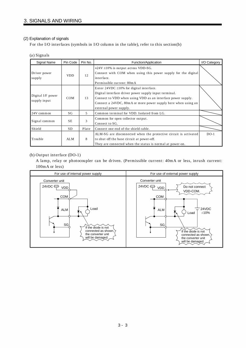
(2) Explanation of signalsFor the I/O interfaces (symbols in I/O column in the table), refer to this section(b)
(a) SignalsSignal Name Pin Code Pin No. Function/Application I/O Category
Driver powersupply VDD 12
24V 10% is output across VDD-SG.Connect with COM when using this power supply for the digitalinterface.Permissible current: 80mA
Digital I/F powersupply input COM 13
Enter 24VDC 10% for digital interface.Digital interface driver power supply input terminal.Connect to VDD when using VDD as an interface power supply.Connect a 24VDC, 80mA or more power supply here when using anexternal power supply.
24V common SG 5 Common terminal for VDD. Isolated from LG.
Signal common SE 3 Common for open collector output.Connect to SG.
Shield SD Plate Connect one end of the shield cable.
Trouble ALM 8ALM-SG are disconnected when the protective circuit is activatedto shut off the base circuit at power-off.They are connected when the status is normal at power-on.
DO-1
(b) Output interface (DO-1)A lamp, relay or photocoupler can be driven. (Permissible current: 40mA or less, inrush current:100mA or less)
For use of internal power supply For use of external power supply
VDD
Converter unit
ALM
If the diode is not connected as shown,the converter unit will be damaged.
24VDC
COM
Load
SG
ALM
SG
VDD24VDC
COM
Converter unit
If the diode is not connected as shown,the converter unit will be damaged.
Load
Do not connectVDD-COM.
24VDC 10%

3 - 4
3. SIGNALS AND WIRING
3.2 Connectors and signal layouts of the servo amplifiers
POINTThe signals are the same as those of the 11k to 22kW servo amplifiers.Refer to the Signal chapter of the corresponding Servo AmplifierInstruction Manual.The pin layouts of the connectors are as seen from the connector wiringsection of the cable.
3.2.1 MELSERVO-J2-Super series
(1) MR-J2S- A/A4
2
4
6
LA
8
LZ
10
1
LG
3
5
7
LB
9
12
14
16
LAR
18
LZR
20
11
LG
13
15
17
LBR
19
CN3
CON2
2
4
6
1
SR
3
5
7
9
AN1
11
13
8
10
12
14
SD
CN2
CN1A
CN1B
CN4
1
2
4
MO1
MO2
LG
LG
BAT
AN0
SDR
LG LG
3MRR
5
7
9
14BAT16P518
20SD
1211
13
15LG17LG
4
6
8P510
2LG
19
1LG
MR
P5
SDRSSR
RXD TXD
Same as the one ofthe MR-J2S-11KA to 22KA.
Same as the one of the MR-J2S-11KA to 22KA.
The connector frames are connected to the PE (earth) terminal in the amplifier.
CN2CN5ACN5B
TE3
TE1
CON2
CN1B
CN1A
CN3
CN4
TE2-2TE2-1
Charge lamp
The MR-HCN2 is mounted.
3 - 5
3. SIGNALS AND WIRING
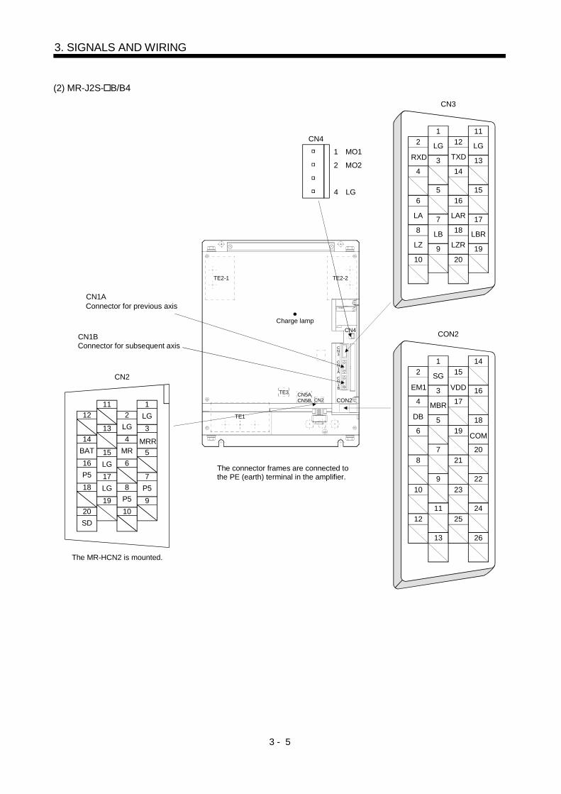
(2) MR-J2S- B/B4
1
2
MO1
MO2
2
4
6
LA
8
LZ
10
1
LG
3
5
7
LB
9
12
14
16
LAR
18
LZR
20
11
LG
13
15
17
LBR
19
CN3
CON2
2
4
6
8
10
1
SG
3
5
7
9
15
17
19
21
23
14
16
18
20
22
1211
13
2524
26
CN2
CN1A
CN1B
CN4
4 LG
3
MRR5
7
9
14BAT16P518
20SD
1211
13
15LG17LG
4
6
8P510
2LG
19
1LG
MR
P5
RXD TXD
EM1
DB
VDD
COM
Connector for previous axis
Connector for subsequent axis
The connector frames are connected to the PE (earth) terminal in the amplifier.
CN2CN5ACN5B
TE3
TE1
CON2
CN1B
CN1A
CN3
CN4
TE2-2TE2-1
Charge lamp
The MR-HCN2 is mounted.
MBR

3 - 6
3. SIGNALS AND WIRING
3.2.2 MELSERVO-H series
(1) MR-H AN/AN4
CN11 (MR-H-D01)
12
14
BAT
16
P5
18
20
11
13
15
LG
17
LG
19
2
LG
4
6
P58
P5
10
1
LG
3
MRR
5
7
9
SD
MR
(M01) 1(M02) 2
(M0G) 4
9
OP5
7
P5
5
PP1D
3
NPRD
1
10
OP24
8
P5
6
NP1D
4
NPD
2
LG
19
SG
17
15
PTR
13
PPRD
11
20
SD
18
P24
16
14
12
PPD
NTR LG
25
23
21
19
17
15
13
11
9
7
5
3
1
24
22
20
18
16
14
12
10
8
6
4
2
50
48
46
44
42
40
38
36
34
32
30
28
26
49
47
45
43
41
39
37
35
33
31
29
27
DO13
DO11
VDD
DI19
SG
DI03
DI01
DO05
DO03
DO01
DI21
DO12
VIND
DI18
SG
DI02
DI00
DO04
DO02
DO00
DI20
SD
DO14
DI17
DI15
DI13
DI10
DI08
DI06
DO09
DI23
DI22
DO15
SG
DI16
DI14
DI12
DI09
DI07
DO10
DO08
DO07
DO06
DI05
DI04
SG
DI11
1
3
5
7
9
11
13
15
17
19
21
23
25
P15R
LG
LAR
LBR
LZR
TL
RES
SG
NPO
VDD
ZSP
TLC
PPR
2
4
6
8
10
12
14
16
18
20
22
24
VC
LA
LB
LZ
PC
SG
PPO
VIN
VDD
PF
SON
PP
N15R
26
28
30
32
34
36
38
40
42
44
46
48
50
LG
LG
FPB
LG
LSP
SG
DI1
DI3
EMG
ALM
SD
NPR
27
29
31
33
35
37
39
41
43
45
47
49
TLAP
FPA
OP
LSN
DI0
DI2
DI4
SG
RD
CR
TLAN
NP
(Note)
(Note)
Note. Used when the MR-H-D01 option card is loaded.
CN12 (MR-H-D01)CN4(For parameter unit)
CN2
CN11CN1
CN3
CN3
CN1
CN2
3 - 7
3. SIGNALS AND WIRING
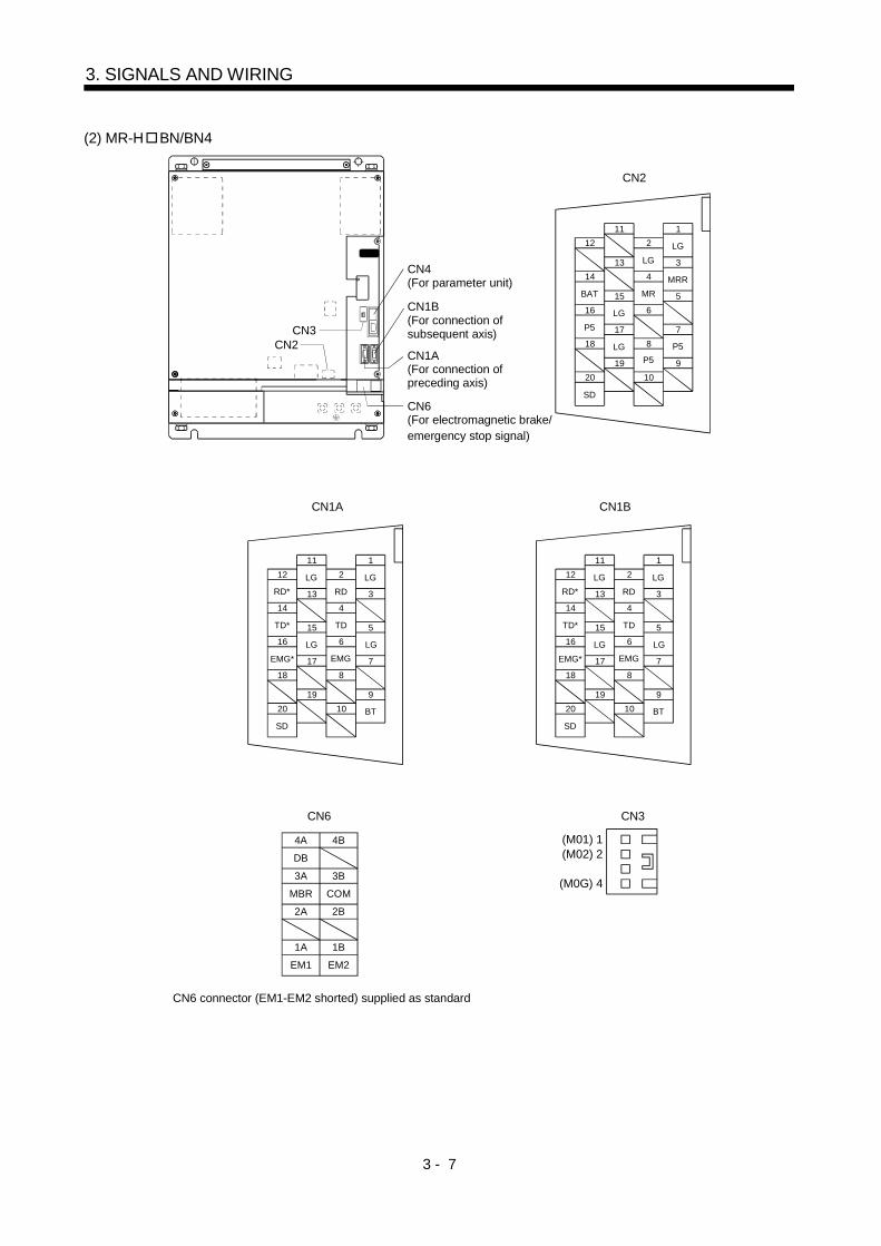
(2) MR-H BN/BN4
12
14
BAT
16
P5
18
20
11
13
15
LG
17
LG
19
2
4
6
LG
8
P5
10
1
LG
3
MRR
5
7
9
SD
MR
P5
DB
4A (M01) 1(M02) 2
(M0G) 4
12
14
TD*
16
EMG*
18
20
11
13
15
LG
17
19
2
4
6
RD
8
10
1
LG
3
5
7
9
SD
TD
BT
LGRD*
EMGLG
12
14
TD*
16
EMG*
18
20
11
13
15
LG
17
19
2
4
6
RD
8
10
1
LG
3
5
7
9
SD
TD
BT
LGRD*
EMGLG
4B
MBR
3A
COM
3B
2A 2B
EM1
1A
EM2
1B
CN6 connector (EM1-EM2 shorted) supplied as standard
CN6(For electromagnetic brake/emergency stop signal)
CN1B(For connection of subsequent axis)
CN4(For parameter unit)
CN2
CN1BCN1A
CN6 CN3
CN3CN2
CN1A(For connection ofpreceding axis)
3 - 8
3. SIGNALS AND WIRING
3.3 Power line circuit
WARNINGInsulate the connections of the power supply terminals. Not doing so can cause anelectric shock.
CAUTION
When the servo amplifier has become faulty, switch power off on the Converterunit power side. Continuous flow of a large current may cause a fire.Use the trouble signal to switch power off. Otherwise, a regenerative braketransistor fault or the like may overheat the regenerative brake resistor, causing afire.Connect the power supply phases (U, V, W) of the servo amplifier and servo motorcorrectly. Not doing so can cause the servo motor to run abnormally.Do not connect a three-phase 200V power supply or a three-phase 400V powersupply directly to the servo motor. Doing so can cause a failure.

3 - 9
3. SIGNALS AND WIRING
3.3.1 Connection example
(1) 200V class
POINTWhen using the external dynamic, Refer to Section 10.1.2.
(a) MR-J2S- A
3-phase200 to 230VAC50/60Hz
MR-A-TM termination connector(Option)
MR-J2HBUS M cable
Converter unit Servo amplifier
Encoder cableFan
Servo motor thermal relay
24VDCpower supply
(Note1)Regenerativebrake option
(Note1)Regenerativebrake option
(Note1)Regenerativebrake option
(Note2)
FanFan Fan
ServoMotor thermal
relayOperation-ready
Dynamicbrake
Servo motor
Converter
Encoder
Power factor improvingDC reactor (Option)
CN1
MCL1
L2
L3
L11
L21
NFB
13 COM
12 VDD
8 ALM
3 SE
5 SG
RA3
P
N
P
N N
P
N
CN5 CN5A
CN2
RA2
OSH1
BW
BV
BU
M
P C
P1
P2
RA1 RA3 RA2 EMG OFF ON
MCMC
SK
VDD
COM
ALM RA1
OHS2
P
V
U
W
CN5B
CN1B
L11
L21
V
U
W
G4G3
P C
G4G3
P C
SR
G4G3
P C
SR SR
NFB
MR-HCN2
3-phase200 to 220VAC/50Hz200 to 230VAC/60Hz
3
13
18
Note 1. For the MR-RB137. For the MR-RB137, three units are used as one set (permissible wattage: 3900W).2. When using the Power factor improving DC reactor, disconnect the short bar across P1-P2.
3 - 10
3. SIGNALS AND WIRING
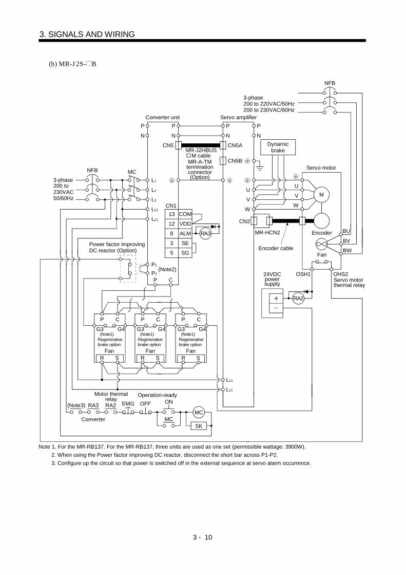
(b) MR-J2S- B
CN1
MCL1
L2
L3
L11
L21
NFB
13 COM
12 VDD
8 ALM
3 SE
5 SG
RA3
P
N
P
N N
P
N
CN5 CN5A
CN2
RA2
OSH1
BW
BV
BU
M
P C
P1
P2
RA3 RA2 EMG OFF ON
MCMC
SK
OHS2
P
V
U
W
CN5B
L11
L21
V
U
W
G4G3
P C
G4G3
P C
SR
G4G3
P C
SR SR
NFB
MR-HCN2
3-phase200 to 230VAC50/60Hz
MR-A-TM termination connector(Option)
MR-J2HBUS M cable
Converter unit Servo amplifier
Encoder cableFan
Servo motor thermal relay
24VDCpower supply
(Note1)Regenerativebrake option
(Note1)Regenerativebrake option
(Note1)Regenerativebrake option
(Note2)
FanFan Fan
Motor thermal relay
Operation-ready
Dynamicbrake
Servo motor
Converter
Encoder
Power factor improvingDC reactor (Option)
3-phase200 to 220VAC/50Hz200 to 230VAC/60Hz
(Note3)
Note 1. For the MR-RB137. For the MR-RB137, three units are used as one set (permissible wattage: 3900W).2. When using the Power factor improving DC reactor, disconnect the short bar across P1-P2.3. Configure up the circuit so that power is switched off in the external sequence at servo alarm occurrence.

3 - 11
3. SIGNALS AND WIRING
(c) MR-H AN
CN1
MCL1
L2
L3
L11
L21
NFB
13 COM
12 VDD
8 ALM
3 SE
5 SG
RA3
P
N
P
N N
P
N
CN5 CN5A
CN2
RA2
OSH1
BW
BV
BU
M
P C
P1
P2
RA1 RA3 RA2 EMG OFF ON
MCMC
SK
VDD
VIN
ALM RA1
OHS2
P
V
U
W
CN5B
CN1
L11
L21
V
U
W
G4G3
P C
G4G3
P C
SR
G4G3
P C
SR SR
NFB
22
20
48
3-phase200 to 230VAC50/60Hz
MR-A-TM termination connector(Option)
MR-J2HBUS M cable
Converter unit Servo amplifier
Encoder cableFan
Servo motor thermal relay
24VDCpower supply
(Note1)Regenerativebrake option
(Note1)Regenerativebrake option
(Note1)Regenerativebrake option
(Note2)
FanFan Fan
ServoMotor thermal
relayOperation-ready
Dynamicbrake
Servo motor
Converter
Encoder
Power factor improvingDC reactor (Option)
3-phase200 to 220VAC/50Hz200 to 230VAC/60Hz
Note 1. For the MR-RB137. For the MR-RB137, three units are used as one set (permissible wattage: 3900W).2. When using the Power factor improving DC reactor, disconnect the short bar across P1-P2.

3 - 12
3. SIGNALS AND WIRING
(d) MR-H BN
CN1
MCL1
L2
L3
L11
L21
NFB
13 COM
12 VDD
8 ALM
3 SE
5 SG
RA3
P
N
P
N N
P
N
CN5 CN5A
CN2
RA2
OSH1
BW
BV
BU
M
P C
P1
P2
RA3 RA2 EMG OFF ON
MCMC
SK
OHS2
P
V
U
W
CN5B
L11
L21
V
U
W
G4G3
P C
G4G3
P C
SR
G4G3
P C
SR SR
NFB
3-phase200 to 230VAC50/60Hz
MR-A-TM termination connector(Option)
MR-J2HBUS M cable
Converter unit Servo amplifier
Encoder cableFan
Servo motor thermal relay
24VDCpower supply
(Note1)Regenerativebrake option
(Note1)Regenerativebrake option
(Note1)Regenerativebrake option
(Note2)
FanFan Fan
Motor thermal relay
Operation-ready
Dynamicbrake
Servo motor
Converter
Encoder
Power factor improvingDC reactor (Option)
3-phase200 to 220VAC/50Hz200 to 230VAC/60Hz
(Note3)
Note 1. For the MR-RB137. For the MR-RB137, three units are used as one set (permissible wattage: 3900W).2. When using the Power factor improving DC reactor, disconnect the short bar across P1-P2.3. Configure up the circuit so that power is switched off in the external sequence at servo alarm occurrence.

3 - 13
3. SIGNALS AND WIRING
(2) 400V class
POINTWhen using the external dynamic, Refer to Section 10.2.2.
(a) MR-J2S- A4
3-phase380 to 480VAC50/60Hz
Converter unit Servo amplifier
MR-A-TM termination connector(Option)
MR-J2HBUS M cable
Servo motor
Dynamicbrake
Fan
Encoder
24VDCpower supply Servo motor
thermal relay
ServoMotor thermal
relay Operation-ready
Step-down trans-former
Fan
(Note1)Regenerativebrake option
Fan Fan
(Note1)Regenerativebrake option
(Note1)Regenerativebrake option
(Note2)
Encoder cable
Converter
Power factor improvingDC reactor (Option)
CN1
MCL1
L2
L3
L11
L21
NFB
13 COM
12 VDD
8 ALM
3 SE
5 SG
RA3
P
N
P
N N
P
N
CN5 CN5A
CN2
RA2
OSH1
BW
BV
BU
M
P C
P1
P2
RA1 RA3 RA2 EMG OFF ON
MCMC
SK
VDD
COM
ALM RA1
OHS2
P
V
U
W
CN5B
CNB1
L11
L21
V
U
W
S400R400
G4G3
P C
S400R400
G4G3
P C
S400R400
G4G3
P C
NFB
MR-HCN2
3-phase380 to 460VAC50/60Hz
3
13
18
Note 1. For the MR-RB138-4. For the MR-RB138-4, three units are used as one set (permissible wattage: 3900W).2. When using the Power factor improving DC reactor, disconnect the short bar across P1-P2.

3 - 14
3. SIGNALS AND WIRING
(b) MR-J2S- B4
CN1
MCL1
L2
L3
L11
L21
NFB
13 COM
12 VDD
8 ALM
3 SE
5 SG
RA3
P
N
P
N N
P
N
CN5 CN5A
CN2
RA2
OSH1
BW
BV
BU
M
P C
P1
P2
RA3 RA2 EMG OFF ON
MCMC
SK
OHS2
P
V
U
W
CN5B
L11
L21
V
U
W
S400R400
G4G3
P C
S400R400
G4G3
P C
S400R400
G4G3
P C
NFB
MR-HCN2
3-phase380 to 480VAC50/60Hz
Converter unit Servo amplifier
MR-A-TM termination connector(Option)
MR-J2HBUS M cable
Servo motor
Dynamicbrake
Fan
Encoder
24VDCpower supply Servo motor
thermal relay
Motor thermalrelay Operation-ready
Step-down trans-former
Fan
(Note1)Regenerativebrake option
Fan Fan
(Note1)Regenerativebrake option
(Note1)Regenerativebrake option
(Note2)
Encoder cable
Converter
Power factor improvingDC reactor (Option)
3-phase380 to 460VAC50/60Hz
(Note3)
Note 1. For the MR-RB138-4. For the MR-RB138-4, three units are used as one set (permissible wattage: 3900W).2. When using the Power factor improving DC reactor, disconnect the short bar across P1-P2.3. Configure up the circuit so that power is switched off in the external sequence at servo alarm occurrence.

3 - 15
3. SIGNALS AND WIRING
(c) MR-H AN4
CN1
MCL1
L2
L3
L11
L21
NFB
13 COM
12 VDD
8 ALM
3 SE
5 SG
RA3
P
N
P
N N
P
N
CN5 CN5A
CN2
RA2
OSH1
BW
BV
BU
M
P C
P1
P2
RA1 RA3 RA2 EMG OFF ON
MCMC
SK
VDD
VIN
ALM RA1
OHS2
P
V
U
W
CN5B
CN1
L11
L21
V
U
W
S400R400
G4G3
P C
S400R400
G4G3
P C
S400R400
G4G3
P C
NFB
22
20
48
3-phase380 to 480VAC50/60Hz
Converter unit Servo amplifier
MR-A-TM termination connector(Option)
MR-J2HBUS M cable
Servo motor
Dynamicbrake
Fan
Encoder
24VDCpower supply Servo motor
thermal relay
ServoMotor thermal
relay Operation-ready
Step-down trans-former
Fan
(Note1)Regenerativebrake option
Fan Fan
(Note1)Regenerativebrake option
(Note1)Regenerativebrake option
(Note2)
Encoder cable
Converter
Power factor improvingDC reactor (Option)
3-phase380 to 460VAC50/60Hz
Note 1. For the MR-RB138-4. For the MR-RB138-4, three units are used as one set (permissible wattage: 3900W).2. When using the Power factor improving DC reactor, disconnect the short bar across P1-P2.

3 - 16
3. SIGNALS AND WIRING
(d) MR-H BN4
CN1
MCL1
L2
L3
L11
L21
NFB
13 COM
12 VDD
8 ALM
3 SE
5 SG
RA3
P
N
P
N N
P
N
CN5 CN5A
CN2
RA2
OSH1
BW
BV
BU
M
P C
P1
P2
RA3 RA2 EMG OFF ON
MCMC
SK
OHS2
P
V
U
W
CN5B
L11
L21
V
U
W
S400R400
G4G3
P C
S400R400
G4G3
P C
S400R400
G4G3
P C
NFB
3-phase380 to 480VAC50/60Hz
Converter unit Servo amplifier
MR-A-TM termination connector(Option)
MR-J2HBUS M cable
Servo motor
Dynamicbrake
Fan
Encoder
24VDCpower supply Servo motor
thermal relay
Motor thermalrelay Operation-ready
Step-down trans-former
Fan
(Note1)Regenerativebrake option
Fan Fan
(Note1)Regenerativebrake option
(Note1)Regenerativebrake option
(Note2)
Encoder cable
Converter
Power factor improvingDC reactor (Option)
3-phase380 to 460VAC50/60Hz
(Note3)
Note 1. For the MR-RB138-4. For the MR-RB138-4, three units are used as one set (permissible wattage: 3900W).2. When using the Power factor improving DC reactor, disconnect the short bar across P1-P2.3. Configure up the circuit so that power is switched off in the external sequence at servo alarm occurrence.

3 - 17
3. SIGNALS AND WIRING
3.3.2 Terminal
Refer to Section 8.2 for the terminal block arrangement and signal layout.
(1) Converter unit
DescriptionConnection Target(Application)
Abbreviation(Note)
Terminal Block MR-HP30KA MR-HP55KA4
Main circuit power supply L1 L2 L3 TE1-2 Connect three-phase 200 to230VAC, 50/60Hz to L1, L2, L3.
Connect three-phase 380 to480VAC, 50/60Hz to L1, L2, L3.
Control circuit power supply L11 L21 TE3 Connect single-phase 200 to230VAC, 50/60Hz.
Connect single-phase 380 to480VAC, 50/60Hz.
Power factor improvingDC reactor P1 P2 TE1-1 When using the Power factor improving DC reactor, connect it after
removing the connection plate across P1-P2.Regenerative brake P C TE1-1 Connect to the P and C terminals of the regenerative brake option.
PN power output P N TE2-1TE2-2
Connect to the P and N terminals of the converter unit.Use the accessory connection bars to make connection.
Grounding PE Connect this terminal to the protective earth (PE) terminals of theservo motor and control box for grounding
Note. The permissible tension applied to any of the terminal blocks TE1-1, TE1-2, TE2-1, TE2-2 is 350[N]. (The testing method is asspecified in Section 8.10.1 (2), JIS C281 "Industrial Terminal Blocks".)
(2) Servo amplifier
DescriptionConnection Target
(Application)Abbreviation
(Note)Terminal Block MR-J2S- A/B MR-H AN/BN
MR-J2S-A4/B4
MR-HAN4/BN4
Servo motor output U V W TE1A Connect to the servo motor power supply terminals (U, V, W).
Control circuit power supply L11 L21 Connect single-phase 200 to230VAC, 50/60Hz.
Connect single-phase 380 to480VAC, 50/60Hz.
PN power supply P N TE2-1TE2-2
Connect to the P and N terminals of the converter unit.Use the accessory connection bars to make connection.
Grounding PE Connect this terminal to the protective earth (PE) terminals of theservo motor and control box for grounding
Note. The permissible tension applied to any of the terminal blocks TE1-1, TE1-2, TE2-1, TE2-2 is 350[N]. (The testing method is asspecified in Section 8.10.1 (2), JIS C281 "Industrial Terminal Blocks".)
3.3.3 How to use the connection bars
Connect P and N of the servo amplifier and P and N of the converter unit using the connection conductorsas shown below.
Converter unitServo amplifier
Connection conductors

3 - 18
3. SIGNALS AND WIRING
3.3.4 Power-on sequence
1) Always wire the power supply as shown in above Section 3.3.1 using the magnetic contactor with themain circuit power supply. Configure up an external sequence to switch off the magnetic contactor assoon as an alarm occurs.
2) Switch on the control circuit power supply L11, L21 simultaneously with the main circuit power supplyor before switching on the main circuit power supply. If the main circuit power supply is not on, thedisplay shows the corresponding warning. However, by switching on the main circuit power supply, thewarning disappears and the servo amplifier will operate properly.
3) The servo amplifier can accept the servo-on signal (SON) about 1 second after the main circuit powersupply is switched on. Therefore, when SON is switched on simultaneously with the three-phase powersupply, the base circuit will switch on in about 1 second, and the ready signal (RD) will switch on infurther about 20ms, making the servo amplifier ready to operate.
CAUTIONTo stop operation and switch power off immediately, provide an external emergencystop circuit.
Make up a circuit which shuts off main circuit power as soon as EMG-SG are opened at an emergencystop. Opening EMG-SG coasts the servo motor. When the optional dynamic brake is used, the servo motorcomes to a sudden stop. At this time, the display shows the servo emergency stop warning (AL.E6).During ordinary operation, do not use the external emergency stop signal to alternate stop and run. If thestart signal is on or a pulse train is input during an emergency stop, the servo motor will rotate as soon asthe warning is reset. During an emergency stop, always shut off the run command. (For next figure is thecase of MR-J2S-A.)
VDD
COM
EMG
SG
Servo amplifier
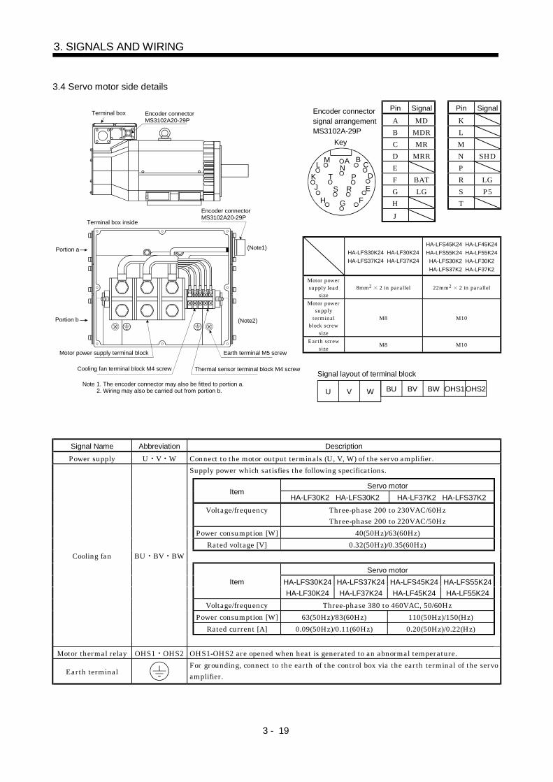
3 - 19
3. SIGNALS AND WIRING
3.4 Servo motor side details
Pin Signal Pin SignalA MD KB MDR LC MR MD MRR N SHDE PF BAT R LGG LG S P5H T
Key
AN
G
S RT P
H F
J EK D
L M BC
Encoder connector signal arrangementMS3102A-29P
J
HA-LFS30K24 HA-LF30K24HA-LFS37K24 HA-LF37K24
HA-LFS45K24 HA-LF45K24HA-LFS55K24 HA-LF55K24
HA-LFS30K2 HA-LF30K2HA-LFS37K2 HA-LF37K2
Motor powersupply lead
size8mm2 2 in parallel 22mm2 2 in parallel
Motor powersupply
terminalblock screw
size
M8 M10
Earth screwsize M8 M10
Terminal box inside
Terminal box Encoder connectorMS3102A20-29P
(Note1)
(Note2)Portion b
Encoder connectorMS3102A20-29P
Portion a
Motor power supply terminal block
Cooling fan terminal block M4 screw
Earth terminal M5 screw
Thermal sensor terminal block M4 screw
Note 1. The encoder connector may also be fitted to portion a.2. Wiring may also be carried out from portion b. U V W BU BV BW OHS1OHS2
Signal layout of terminal block
Signal Name Abbreviation DescriptionPower supply U V W Connect to the motor output terminals (U, V, W) of the servo amplifier.
Supply power which satisfies the following specifications.
Servo motorItem
HA-LF30K2 HA-LFS30K2 HA-LF37K2 HA-LFS37K2Voltage/frequency Three-phase 200 to 230VAC/60Hz
Three-phase 200 to 220VAC/50HzPower consumption [W] 40(50Hz)/63(60Hz)
Rated voltage [V] 0.32(50Hz)/0.35(60Hz)
Servo motorItem HA-LFS30K24
HA-LF30K24HA-LFS37K24HA-LF37K24
HA-LFS45K24HA-LF45K24
HA-LFS55K24HA-LF55K24
Voltage/frequency Three-phase 380 to 460VAC, 50/60HzPower consumption [W] 63(50Hz)/83(60Hz) 110(50Hz)/150(Hz)
Rated current [A] 0.09(50Hz)/0.11(60Hz) 0.20(50Hz)/0.22(Hz)
Cooling fan BU BV BW
Motor thermal relay OHS1 OHS2 OHS1-OHS2 are opened when heat is generated to an abnormal temperature.
Earth terminalFor grounding, connect to the earth of the control box via the earth terminal of the servoamplifier.
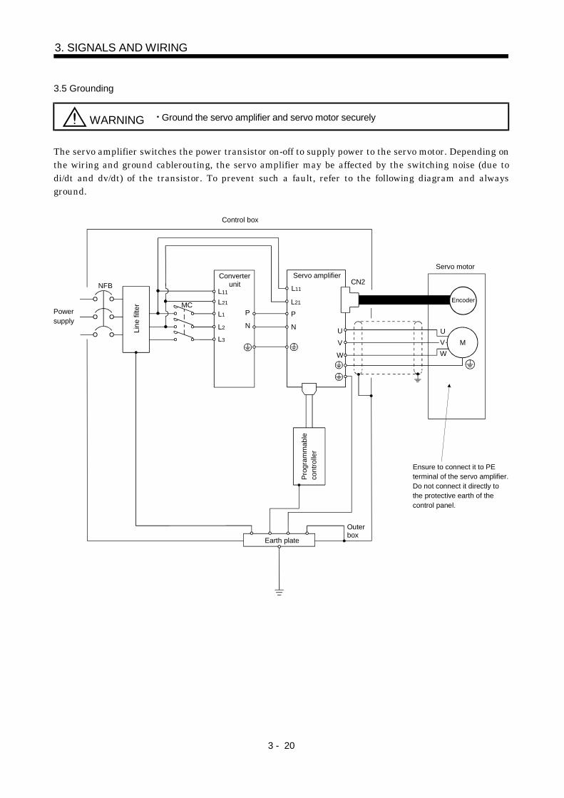
3 - 20
3. SIGNALS AND WIRING
3.5 Grounding
WARNING Ground the servo amplifier and servo motor securely
The servo amplifier switches the power transistor on-off to supply power to the servo motor. Depending onthe wiring and ground cablerouting, the servo amplifier may be affected by the switching noise (due todi/dt and dv/dt) of the transistor. To prevent such a fault, refer to the following diagram and alwaysground.
Control box
Servo amplifier
L11
L21
P
NLine
filte
r
NFB
MC
Earth plate
CN2
UV
W
Outerbox
Servo motor
MUVW
Powersupply
Ensure to connect it to PEterminal of the servo amplifier.Do not connect it directly tothe protective earth of the control panel.
L2
L3
L1
L21
L11
Converterunit
P
N
Prog
ram
mab
leco
ntro
ller
Encoder

4 - 1
4. DISPLAY SECTION AND OPERATION SECTION OF THE CONVERTER UNIT
4. DISPLAY SECTION AND OPERATION SECTION OF THE CONVERTER UNIT
4.1 Display flowchart
Use the display (4-dight, 7-segment LED) on the front panel of the Converter unit for status display,parameter setting, etc. Set the parameters before operation, diagnose an alarm, confirm externalsequences, and/or confirm the operation status.Press the MODE, UP or DOWN button once to move the next screen.
MODE
DOWN
UP
Bus voltage
Effective load ratio
Peak load ratio
Within one-revolution position [%]
Sequence Current alarm ParameterNo.0
External I/O signal
Softwareversion L
Status display Diagnosis Alarm Basic parameters
button
Last alarm
Softwareversion H
ParameterNo.1
ParameterNo.9
ParameterNo.8
ParametererrorNo.
Tenth alarm in past
Output signalforced output

4 - 2
4 DISPLAY SECTION AND OPERATION SECTION OF THE CONVERTER UNIT
4.2 Status display mode
The servo status during operation is shown on the 4-digit, 7-segment LED display. Press the "UP" or"DOWN" button to change display data as desired.When the required data is selected, the corresponding symbol is displayed. Press the "SET" button todisplay that data.The converter unit display section can show four items of data such as the effective load factor.
4.2.1 Display examples
The following table shows the display examples.Item Status Display
Bus voltage 225[V]
Effective load factor 67[%]
Peak load factor 95[%]
Regenerative load factor 90[%]
4.2.2 Status display list
The following table lists the servo statuses that may be displayed.Status Display Symbol Unit Description Indication Range
Bus voltage d V The converter unit voltage is displayed. 0 to 500
Effective load factor J %Continuous effective load torque is displayed. (Note)The effective value in the past 15 seconds is displayedrelative to the rated current of 100%.
0 to 300
Peak load factor b %The peak output is displayed. (Note)The peak value in the past 15 seconds is displayedrelative to the rated torque of 100%.
0 to 300
Regenerative loadfactor
L %The percentage of regenerative power to thepermissible regenerative value is displayed.
0 to 300
Note. Output speed torque
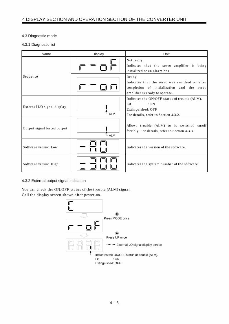
4 - 3
4 DISPLAY SECTION AND OPERATION SECTION OF THE CONVERTER UNIT
4.3 Diagnostic mode
4.3.1 Diagnostic list
Name Display Unit
Not ready.Indicates that the servo amplifier is beinginitialized or an alarm has
Sequence ReadyIndicates that the servo was switched on aftercompletion of initialization and the servoamplifier is ready to operate.
External I/O signal display
ALM
Indicates the ON/OFF status of trouble (ALM).Lit : ONExtinguished: OFFFor details, refer to Section 4.3.2.
Output signal forced output
ALM
Allows trouble (ALM) to be switched on/offforcibly. For details, refer to Section 4.3.3.
Software version Low Indicates the version of the software.
Software version High Indicates the system number of the software.
4.3.2 External output signal indication
You can check the ON/OFF status of the trouble (ALM) signal.Call the display screen shown after power-on.
External I/O signal display screen
Indicates the ON/OFF status of trouble (ALM).Lit : ONExtinguished: OFF
Press MODE once
Press UP once
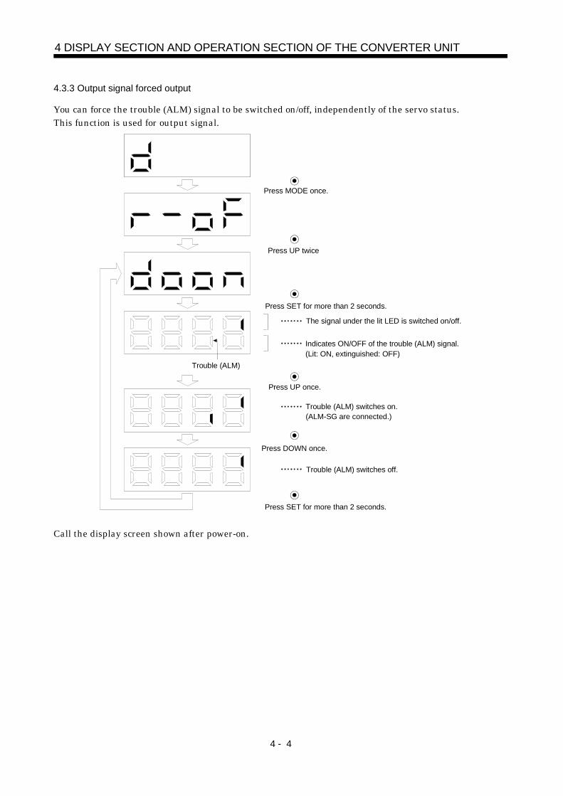
4 - 4
4 DISPLAY SECTION AND OPERATION SECTION OF THE CONVERTER UNIT
4.3.3 Output signal forced output
You can force the trouble (ALM) signal to be switched on/off, independently of the servo status.This function is used for output signal.
Press MODE once.
Press UP twice
Press SET for more than 2 seconds.
Press SET for more than 2 seconds.
Trouble (ALM)
The signal under the lit LED is switched on/off.
Indicates ON/OFF of the trouble (ALM) signal.(Lit: ON, extinguished: OFF)
Press UP once.
Press DOWN once.
Trouble (ALM) switches on.(ALM-SG are connected.)
Trouble (ALM) switches off.
Call the display screen shown after power-on.

4 - 5
4 DISPLAY SECTION AND OPERATION SECTION OF THE CONVERTER UNIT
4.4 Alarm mode
The current alarm, parameter error and point table error are displayed.The lower 2 digits on the display indicate the alarm number that has occurred or the parameter numberin error.Display example are shown below.
Name Display Description
Indicates on occurrence of an alarm.Current alarm
Indicates that overvoltage (A.33) occurred.Flickers at alarm occurrence.
Indicates that the last alarm is overload (A.50).
Indicates that the second alarm in the past is overvoltage(A.33).
Indicates that the third alarm in the past is undervoltage(A.10).
Indicates that the fourth alarm in the past is undervoltage(A.10).
Indicates that the fifth alarm in the past is undervoltage(A.10).
Indicates that the sixth alarm in the past is overload(A.50).
Indicates that there is no seventh alarm in the past.
Indicates that there is no eighth alarm in the past.
Indicates that there is no ninth alarm in the past.
Alarm history
Indicates that there is no tenth alarm in the past.
Indicates no occurrence of parameter error (A37).Parameter error
Indicates that the data of parameter No.1 is faulty.
Functions at occurrence of an alarm(1) Any mode screen displays the current alarm.(2) The other screen is visible during occurrence of an alarm. At this time, the decimal point in the fourth
digit flickers.(3) To clear any alarm, switch power off, then on or press the "SET" button on the current alarm screen.
Note that this should be done after removing the case of the alarm.

4 - 6
4 DISPLAY SECTION AND OPERATION SECTION OF THE CONVERTER UNIT
4.5 Parameter mode
The following example gives the operation procedure after power-on for use of the regenerative brakeoptions (MR-RB137).
Press MODE three time
The parameter number is displayed.
Press UP or DOWN to change the number.
Press UP twice
The set value of the specified parameter number flickers.
Press UP fourthDuring flickering, the set value can be change.
Use UP or DOWN .
Press SET to enter.
( 4: MR-RB137 (3 pcs.) are used)
To shift to the next parameter, press the "UP"/"DOWN" button.When changing the parameter No.0 setting, change its set value, then switch power off once and switch iton again to make the new value valid.

5 - 1
5. PARAMETER
5. PARAMETER
5.1 Converter unit
No. Symbol Name and functionInitialvalue
UnitControlMode
0 STY Control mode, regenerative brake option selectionUsed to select the control mode regenerative brake option.
0 00
Select the regenerative brake option."1" and "2" are provided for maker adjustment and should not be set.0: No used1: MR-RB136-42: MR-RB138-4 (3pcs.)3: MR-RB1394: MR-RB137 (3 pcs.)
Only for MR-HP55KA4
Only for MR-HP30KA
"1" and "2" are the set values for the MR-HP55KA4only, and "3" and "4" are those for the MR-HP30KAonly.Wrong setting will result in parameter alarm (AL.37).
0000 Refer toNameand
functioncolumn.
1 00002 00003
For manufacturerDo not change this value any means.
00014 DMD Status display selection
Used to select the status display shown at power-on.
0 00
Status display of converter unit display section at power-on.0: Bus voltage (initial value)1: Effective load ratio2: Peak load ratio3: Regenerative load ratio
0000 Refer toNameand
functioncolumn.
5 ACL Alarm history clearUsed to select alarm history clear
0 00
Alarm history clear0: Invalid1: Valid
Used to select alarm history clear. When alarm history clear is made valid, the alarm history is cleared at next power-on.After the alarm history is cleared,the setting is automatically made invalid (reset to 0).
0000 Refer toNameand
functioncolumn.
6 07 08 09
For manufacturerDo not change this value any means.
0000

5 - 2
5. PARAMETER
5.2 Servo amplifier
POINTThe parameters of each servo amplifier are basically the same as those ofthe 11k to 22kW servo amplifier. This section describes the differences inparameters between each servo amplifier and the 11k to 22kW servoamplifier.
5.2.1 MELSERVO-J2-Super series
(1) MR-J2S-No. Symbol Name and function Initial value Unit
0 *STY Control mode/regenerative brake option selection
00
Refer to the MR-J2S- A Servo Amplifier Instruction Manual.
Regenerative brake option selectionAlways set "0".
00000
(2) MR-J2S- A4No. Symbol Name and function Initial value Unit
0 *STY Control mode/regenerative brake option selection
00
Refer to the MR-J2S- A Servo Amplifier Instruction Manual.
Regenerative brake option selectionAlways set "0".
00000
17 MOD Analog monitor output
Setting
0
Analog monitor 2 (MO2)
Servo motor speed ( 8V/max. speed)1 Torque ( 8V/max. torque)2 Motor speed ( 8V/max. speed)3 Torque ( 8V/max. torque)4 Current command ( 8V/max. current command)5 Command speed ( 8/max. speed)6 Droop pulses ( 10V/128 pulses)7 Droop pulses ( 10V/2048 pulses)8 Droop pulses ( 10V/8192 pulses)9 Droop pulses ( 10V/32768 pulses)A Droop pulses ( 10V/131072 pulses)
00
B Bus voltage ( 8V/800V)
Analog monitor 1 (MO1)
0100
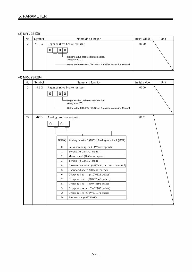
5 - 3
5. PARAMETER
(3) MR-J2S- BNo. Symbol Name and function Initial value Unit
2 *REG Regenerative brake resistor
0
Regenerative brake option selectionAlways set "0".
Refer to the MR-J2S- B Servo Amplifier Instruction Manual.
0 0
0000
(4) MR-J2S- B4No. Symbol Name and function Initial value Unit
2 *REG Regenerative brake resistor
0
Regenerative brake option selectionAlways set "0".
Refer to the MR-J2S- B Servo Amplifier Instruction Manual.
0 0
0000
22 MOD Analog monitor output
Setting
0 Servo motor speed ( 8V/max. speed)1 Torque ( 8V/max. torque)2 Motor speed ( 8V/max. speed)3 Torque ( 8V/max. torque)4 Current command ( 8V/max. current command)5 Command speed ( 8/max. speed)6 Droop pulses ( 10V/128 pulses)7 Droop pulses ( 10V/2048 pulses)8 Droop pulses ( 10V/8192 pulses)9 Droop pulses ( 10V/32768 pulses)A Droop pulses ( 10V/131072 pulses)
00
B Bus voltage ( 8V/800V)
Analog monitor 1 (MO1) Analog monitor 2 (MO2)
0001
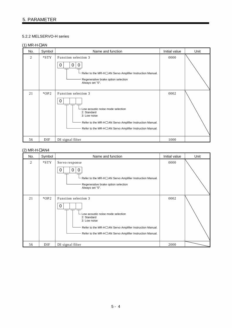
5 - 4
5. PARAMETER
5.2.2 MELSERVO-H series
(1) MR-H- ANNo. Symbol Name and function Initial value Unit
2 *STY Function selection 3
00
Refer to the MR-H AN Servo Amplifier Instruction Manual.
Regenerative brake option selectionAlways set "0".
0
0000
21 *OP2 Function selection 3
0
Low acoustic noise mode selection2: Standard3: Low noise
Refer to the MR-H AN Servo Amplifier Instruction Manual.
Refer to the MR-H AN Servo Amplifier Instruction Manual.
0002
56 DIF DI signal filter 1000
(2) MR-H- AN4No. Symbol Name and function Initial value Unit
2 *STY Servo response
00
Refer to the MR-H AN Servo Amplifier Instruction Manual.
Regenerative brake option selectionAlways set "0".
0
0000
21 *OP2 Function selection 3
0
Low acoustic noise mode selection2: Standard3: Low noise
Refer to the MR-H AN Servo Amplifier Instruction Manual.
Refer to the MR-H AN Servo Amplifier Instruction Manual.
0002
56 DIF DI signal filter 2000

5 - 5
5. PARAMETER
(3) MR-H BN/BN4No. Symbol Name and function Initial value Unit
2 *REG Regenerative brake resistor
Refer to the MR-H BN Servo Amplifier Instruction Manual.
0
Regenerative brake option selectionAlways set "0".
0 0
0000
23 *OP1 Optional function 1
0
Low acoustic noise mode selection2: Standard3: Low noise
0 0
0020

5 - 6
5. PARAMETER
MEMO
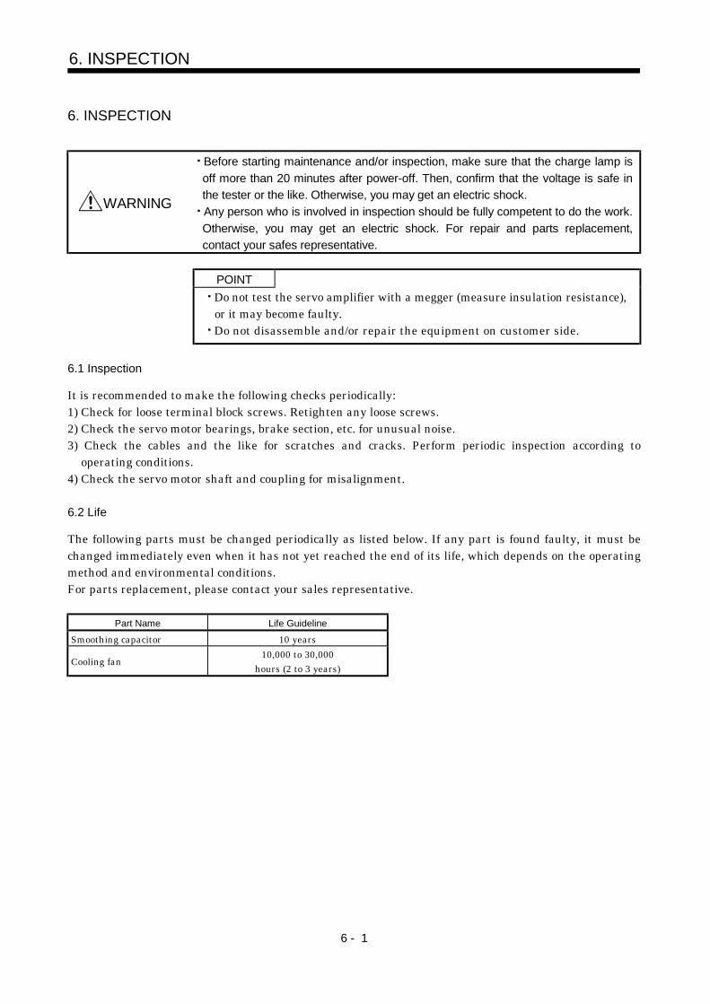
6 - 1
6. INSPECTION
6. INSPECTION
WARNING
Before starting maintenance and/or inspection, make sure that the charge lamp isoff more than 20 minutes after power-off. Then, confirm that the voltage is safe inthe tester or the like. Otherwise, you may get an electric shock.Any person who is involved in inspection should be fully competent to do the work.Otherwise, you may get an electric shock. For repair and parts replacement,contact your safes representative.
POINTDo not test the servo amplifier with a megger (measure insulation resistance),or it may become faulty.Do not disassemble and/or repair the equipment on customer side.
6.1 Inspection
It is recommended to make the following checks periodically:1) Check for loose terminal block screws. Retighten any loose screws.2) Check the servo motor bearings, brake section, etc. for unusual noise.3) Check the cables and the like for scratches and cracks. Perform periodic inspection according to
operating conditions.4) Check the servo motor shaft and coupling for misalignment.
6.2 Life
The following parts must be changed periodically as listed below. If any part is found faulty, it must bechanged immediately even when it has not yet reached the end of its life, which depends on the operatingmethod and environmental conditions.For parts replacement, please contact your sales representative.
Part Name Life GuidelineSmoothing capacitor 10 years
Cooling fan 10,000 to 30,000hours (2 to 3 years)

6 - 2
6. INSPECTION
(1) Smoothing capacitorAffected by ripple currents, etc. and deteriorates in characteristic. The life of the capacitor greatlydepends on ambient temperature and operating conditions. The capacitor will reach the end of its lifein 10 years of continuous operation in normal air-conditioned environment.
(2) RelaysTheir contacts will wear due to switching currents and contact faults occur. Relays reach the end oftheir life when the cumulative number of power-on and emergency stop times is 100,000, whichdepends on the power supply capacity.
(3) Converter unit/Servo amplifier cooling fanThe cooling fan bearings reach the end of their life in 10,000 to 35,000 hours. Normally, therefore, thefan must be changed in a few years of continuous operation as a guideline.It must also be changed if unusual noise or vibration is found during inspection.
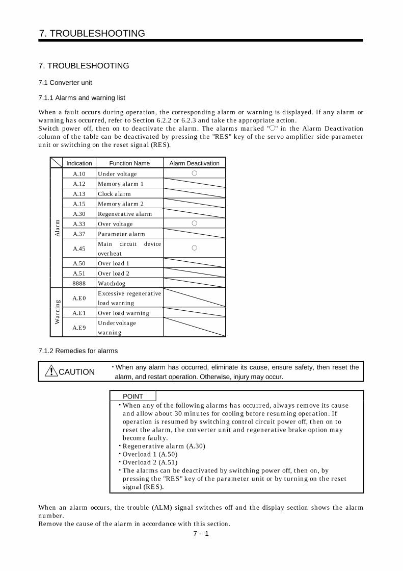
7 - 1
7. TROUBLESHOOTING
7. TROUBLESHOOTING
7.1 Converter unit
7.1.1 Alarms and warning list
When a fault occurs during operation, the corresponding alarm or warning is displayed. If any alarm orwarning has occurred, refer to Section 6.2.2 or 6.2.3 and take the appropriate action.Switch power off, then on to deactivate the alarm. The alarms marked " " in the Alarm Deactivationcolumn of the table can be deactivated by pressing the "RES" key of the servo amplifier side parameterunit or switching on the reset signal (RES).
Indication Function Name Alarm Deactivation
A.10 Under voltageA.12 Memory alarm 1A.13 Clock alarmA.15 Memory alarm 2A.30 Regenerative alarmA.33 Over voltageA.37 Parameter alarm
A.45Main circuit deviceoverheat
A.50 Over load 1A.51 Over load 2
Alar
m
8888 Watchdog
A.E0Excessive regenerativeload warning
A.E1 Over load warning
War
ning
A.E9Undervoltagewarning
7.1.2 Remedies for alarms
CAUTION When any alarm has occurred, eliminate its cause, ensure safety, then reset thealarm, and restart operation. Otherwise, injury may occur.
POINTWhen any of the following alarms has occurred, always remove its causeand allow about 30 minutes for cooling before resuming operation. Ifoperation is resumed by switching control circuit power off, then on toreset the alarm, the converter unit and regenerative brake option maybecome faulty.Regenerative alarm (A.30)Overload 1 (A.50)Overload 2 (A.51)The alarms can be deactivated by switching power off, then on, bypressing the "RES" key of the parameter unit or by turning on the resetsignal (RES).
When an alarm occurs, the trouble (ALM) signal switches off and the display section shows the alarmnumber.Remove the cause of the alarm in accordance with this section.

7 - 2
7. TROUBLESHOOTING
Indication Name Definition Cause Action1. Power supply voltage is low.2. Instantaneous control power failure
occurred for more than 100ms.3. Power switched on within 5s after it
had switched off.4. Shortage of power supply capacity
caused the power supply voltage todrop at start, etc.
Review the power supply.A.10 Undervoltage Control power supplyvoltage dropped to thefollowing voltage.
5. Faulty parts in the servo amplifierChecking method
Alarm (A.10) occurs if power isswitched on after connectorsdisconnected.
Change the Converter unit.
A.12 Memory alarm 1 RAM, ROM memoryfault
A.13 Clock alarm Printed board faultA.15 Memory alarm 2 EEP-ROM fault
Failure of the part in the converter unit.Checking method
Alarm (A.10, A.13, A.15) occursif power is switched on after connectors disconnected.
Change the Converter unit.
1. Wrong setting of parameter No. 0 Set correctly.2. Regenerative brake option is not
connected.Connect correctly.
3. High-duty operation or continuousregenerative operation caused thepermissible regenerative power ofthe regenerative brake option to beexceeded.
Checking methodCall the status display and checkthe regenerative load ratio.
1. Reduce the frequency ofpositioning.
2. Use the regenerative brakeoption of larger capacity.
3. Reduce the load.
4. Power supply voltage is abnormal.MR-HP30KA: 260VAC or moreMR-HP55KA4: 520VAC or more
Review power supply
5. Regenerative transistor faulty.Checking method
1) The regenerative brake option has overheated abnormally.2) The alarm occurs even after removal of the built-in regenerative brake resistor or regenerative brake option.
Change the Converter unit.
6. Regenerative brake option faulty. Change Converter unit orregenerative brake option.
A.30 Regenerativealarm
Permissibleregenerative power ofthe built-inregenerative brakeresistor orregenerative brakeoption is exceeded.
7. Unusual overheat due to cooling fanstop
1. Change the Converter unit orcooling fan.
2. Reduce ambient temperature.1. Regenerative brake option is not
used.Use the regenerative brakeoption.
2. Though the regenerative brakeoption is used, the parameter No. 0setting is " 0 (not used)".
Make correct setting.
3. Lead of regenerative brake option isopen or disconnected.
1. Change lead.2. Connect correctly.
4. Regenerative transistor faulty.5. Wire breakage of regenerative
brake option1. For wire breakage of built-in
regenerative brake resistor,change Converter unit.
2. For wire breakage of regenerativebrake option, change regenerativebrake option.
A.33 Over voltage Converter bus voltageexceeded to followingvoltage.MR-HP30KA: 400VDCMR-HP55KA4: 800VDC
6. Capacity of regenerative brakeoption is insufficient.
Add regenerative brake option orincrease capacity.
1. Servo amplifier fault caused theparameter setting to be rewritten.
Change the Converter unit.A.37 Parameteralarm
Parameter setting iswrong.
2. Parameter data improper-setting. Set parameter correctly.1. Converter unit faulty. Change the Converter unit2. The power supply was turned on and
off continuously by overloaded status.The drive method is reviewed.
A.45 Main circuitdevice overheat
Main circuit deviceoverheat
3. Air cooling fan of servo amplifier stops. The cooling method is reviewed.

7 - 3
7. TROUBLESHOOTING
Indication Name Definition Cause ActionA.50 Over load 1 Load exceeded overload
protection characteristicof Converter unit
Converter unit is used in excess of itscontinuous output current.
1. Reduce load.2. Review operation pattern.
A.51 Overload 2 Machine collision or thelike caused max. outputcurrent to flowsuccessively for severalseconds.
Machine struck something. 1. Review operation pattern.2. Install limit switches.
8888 Watchdog CPU/part is faulty. Failure of the part in the converterunit.
Checking methodAlarm (8888) occurs if all connectors are disconnected and power is switched on.
Change the converter unit.
7.1.3 Remedies for warnings
Continuing operation in an alarm occurrence status may result in an alarm or disable proper operation.Eliminate the cause of the warning according to this section. The warning displayed will disappearwhen the cause of its occurrence is resolved.Indication Name Definition Cause ActionA.E0 Excessive
regenerativeload warning
There is a possibilitythat regenerative powermay exceed permissibleregenerative power ofregenerative brakeoption.
Regenerative power increased to 85%or more of permissible regenerativepower of built-in regenerative brakeresistor or regenerative brake option.
Checking methodCall the status display and checkregenerative load ratio.
1. Reduce frequency ofpositioning.
2. Change regenerative brakeoption for the one with largercapacity.
3. Reduce load.
A.E1 Over loadwarning
There is a possibilitythat overload alarm 1 or2 may occur.
Load increased to 85% or more ofoverload alarm 1 or 2 occurrencelevel.
Cause, checking methodRefer to A.50,51.
Refer to A.50, A.51.
1. Power supply voltage is low. Review power supply.A.E9 Undervoltagewarning
Bus voltage dropped.MR-HP30KA: 180VMR-HP55KA4: 360V 2. P and/or N is not connected. Carry out wiring properly.
7.1.4. Clearing the alarm history
You can clear the alarm numbers stored in the alarm history of the alarm mode. To ensure that you cancontrol the alarms that will occur after regular operation, make this setting before starting regularoperation to clear the alarm history.After setting "0001" in parameter No. 5, switch power off once. Switching it on again clears the alarmhistory. At this time, the parameter No. 5 setting returns to "0000".
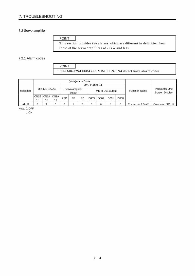
7 - 4
7. TROUBLESHOOTING
7.2 Servo amplifier
POINTThis section provides the alarms which are different in definition fromthose of the servo amplifiers of 22kW and less.
7.2.1 Alarm codes
POINT The MR-J2S- B/B4 and MR-H BN/BN4 do not have alarm codes.
(Note)Alarm CodeMR-H AN/AN4
MR-J2S- A/A4 Servo amplifieroutput
MR-H-D01 outputIndication
CN1B19
CN1A18
CN1A19
ZSP PF RD D003 D002 D001 D000
Function NameParameter UnitScreen Display
AL.1b 0 1 0 0 1 0 0 0 1 0 Converter RD off Converter RD offNote. 0: OFF
1: ON

7 - 5
7. TROUBLESHOOTING
7.2.2 Alarm corrective actions
POINTThe parameter unit screen is displayed by the MELSERVO-H series.
Parameter Unit Screen Display
Indication Name Definition Current Alarm(name anddefinition)
AlarmOccurrence
Factor
Cause Action
Power Voltunder 160V15 ms IPF
1. Bus voltage (across P-N) of theconverter unit dropped to less thanthe following voltage.200V class: 200VDC400V class: 400VDC
Power Voltunder 160V15ms IPF
2. Power failed instantaneously.Main circuit power supply: 10ms or lessControl circuit power supply: 100ms orless
Insuf. Powercapacity
3. Shortage of power supply capacitycaused the power supply voltage todrop at start, etc.
Review thepower supply.
4. Power switched on within 5s after ithad switched off.
AL.10 Undervoltage
Converter unitvoltage dropped.
Under volt
5. Faulty parts in the servo amplifier
Checking methodAlarm (AL.10) occurs if power isswitched on after all connectorsare disconnected.
Change theServo amplifier.
1. Bus voltage is low.Al.1b ConverterRD off
Servo on (SON)signal switched onwhen the ready(RD) of theconverter was off.
Converter RDoff
Converter RDoff 2. Alarm occurred in the converter.
Remove thecause of theconverter alarmand deactivatethe alarm.
Reg. Resist. Hastrouble
1. Lead of regenerative brake option isopen or disconnected.
1. Change lead.2. Connect
correctly.Reg. Tr.damaged
2. Regenerative brake transistor failed.
Reg. Resist hastrouble
3. Wire breakage of built-inregenerative brake resistor orregenerative brake option
4. Capacity of regenerative brakeoption is insufficient.
Increaseregenerativebrake optioncapacity.
AL.33 Overvoltage
Converter busvoltage exceededto followingvoltage.200V class:
400VDC400V class:
800VDC.
Over volt.
Power voltexceeded
5. Power supply voltage high. Review thepower supply.

7 - 6
7. TROUBLESHOOTING
MEMO
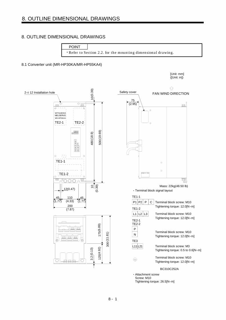
8 - 1
8. OUTLINE DIMENSIONAL DRAWINGS
8. OUTLINE DIMENSIONAL DRAWINGS
POINTRefer to Section 2.2. for the mounting dimensional drawing.
8.1 Converter unit (MR-HP30KA/MR-HP55KA4)
Tightening torque: 0.5 to 0.6[N m]
Mass: 22kg(48.50 lb)
BC310C252A
Terminal block signal layout
P1 P2 P C
TE1-1
L1 L2 L3
TE1-2
P
TE2-1TE2-2
N
L11 L21
TE3
3.2
MITSUBISHIMELSERVOMR-HP55KA4
TE2-1 TE2-2
480
500
10
12(0.47)
175
300
Safety cover
75(2.95)
FAN WIND DIRECTION
MITSUBISHI AC SERVO
45(1.77)
10
110(4.33)200
(7.87)
125
TE1-2
TE1-1
[Unit: mm] ([Unit: in])
(0.3
9)(1
8.9)
(19.
69)
(0.3
9)
45(1.77)
(6.8
9)
(11.
81)
(4.9
2)
(0.1
3)
Terminal block screw: M10
Terminal block screw: M10
Terminal block screw: M3
2- 12 Installation hole
Tightening torque: 12.0[N m]
Tightening torque: 12.0[N m]
Terminal block screw: M10Tightening torque: 12.0[N m]
Terminal block screw: M10Tightening torque: 12.0[N m]
Attachment screwScrew: M10Tightening torque: 26.5[N m]

8 - 2
8. OUTLINE DIMENSIONAL DRAWINGS
8.2 Servo amplifier
8.2.1 MELSERVO-J2-Super series
[Unit: mm]([Unit: in])
Variable Dimensions [mm]([in])Servo Amplifier
A BMass
[kg]([lb])MR-J2S-30KA4/B4 290 (11.42) 380 (14.96) 36 (79.37)
MR-J2S-30KA/BMR-J2S-37KA/B
MR-J2S-37KA4/B4MR-J2S-45KA4/B4MR-J2S-55KA4/B4
360 (14.17) 450 (17.72) 47 (103.62)
10(0
.39)
3.
2 (0
.13)
10(0
.39)
12(0.47)
CN5ACN5B CN2L11 L21
TE3
TE1
TE2-1 TE2-2
75(2.953) 330 (12.99)
45 (1.77) B
A 45 (1.77)
391
(15.
39)
36 (1
.417
)
480
(18.
9)
500
(19.
69)
217
(8.5
43)
198.
5 (7
.815
)
175
(6.8
9)30
0 (1
1.81
)12
5 (4
.92)
75(2.95)
Terminal block screw: M3Tightening torque: 0.5 to 0.6[N m]
Terminal block screw: M10Tightening torque: 12.0[N m]
P
N
TE1
TE2-1TE2-2
U V W
L11 L21
TE3
Terminal block signal layout
Terminal block screw: M10Tightening torque: 12.0[N m]
Terminal block screw: M10Tightening torque: 12.0[N m]
2- 12 Installation hole FAN WIND DIRECTION
Safety cover(Note)
2 30 60(0.079 1.181 2.362)
Attachment screwScrew: M10Tightening torque: 26.5[N m]
2 36 72(0.079 1.417 2.835)
Note. For the MR-J2S-30KA4/B4, the fan is built in.
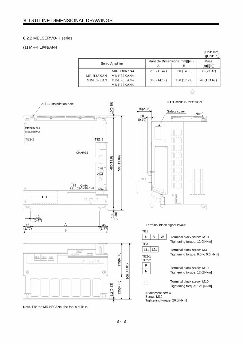
8 - 3
8. OUTLINE DIMENSIONAL DRAWINGS
8.2.2 MELSERVO-H series
(1) MR-H AN/AN4[Unit: mm]([Unit: in])
Variable Dimensions [mm]([in])Servo Amplifier
A BMass
[kg]([lb])MR-H30KAN4 290 (11.42) 380 (14.96) 36 (79.37)
MR-H3AKANMR-H37KAN
MR-H37KAN4MR-H45KAN4MR-H55KAN4
360 (14.17) 450 (17.72) 47 (103.62)
TE2-1 TE2-2
TE1
TE3
CHARGE
CN2CN5ACN5BL11 L21
Safety cover
MITSUBISHIMELSERVO
CN1
CN4
CN3
FAN WIND DIRECTION
75(2.95)
20(0.79)
12(0.47)
45(1.77)
A
B
480(
18.9
)10
(0.3
9)10
(0.3
9)
500(
19.6
9)
MIT
SUB
ISH
IAC
SERV
O
2- 12 Installation hole
45(1.77)
175(
6.89
)
300
(11.
81)
125(
4.92
)
3.2
(0.1
3)(Note)
Terminal block screw: M10Tightening torque: 12.0[N m]
P
N
TE1
TE2-1TE2-2
U V W
TE3
Terminal block signal layout
Terminal block screw: M3Tightening torque: 0.5 to 0.6[N m]
Terminal block screw: M10Tightening torque: 12.0[N m]
Terminal block screw: M10Tightening torque: 12.0[N m]
L11 L21
Attachment screwScrew: M10Tightening torque: 26.5[N m]
Note. For the MR-H30AN4, the fan is built in.

8 - 4
8. OUTLINE DIMENSIONAL DRAWINGS
(2) MR-H30KBN/BN4[Unit: mm]([Unit: in])
Variable Dimensions [mm]([in])Servo Amplifier
A BMass
[kg]([lb])MR-H30KBN4 290 (11.42) 380 (14.96) 36 (79.37)
MR-H30KBNMR-H37KBN
MR-H37KBN4MR-H45KBN4MR-H55KBN4
360 (14.17) 450 (17.72) 47 (103.62)
A
B
TE2-1 TE2-2
TE1
TE3
CHARGE
CN2CN5ACN5BL11 L21
MITSUBISHIMELSERVO
75(2.95)
20(0.79)
12(0.47)
45(1.77)
480(
18.9
)10
(0.3
9)10
(0.3
9)
500(
19.6
9)
2- 12 Installation hole
45(1.77)
175(
6.89
)
300
(11.
81)
125(
4.92
)
3.2
(0.1
3)
CN1BCN1A
CN6
CN3 CN4
Safety cover
FAN WIND DIRECTION
MIT
SUBI
SH
IAC
SER
VO
110(4.33)
(Note)
Terminal block screw: M10Tightening torque: 12.0[N m]
P
N
TE1
TE2-1TE2-2
U V W
TE3
Terminal block signal layout
Terminal block screw: M3Tightening torque: 0.5 to 0.6[N m]
Terminal block screw: M10Tightening torque: 12.0[N m]
Terminal block screw: M10Tightening torque: 12.0[N m]
L11 L21
Attachment screwScrew: M10Tightening torque: 26.5[N m]
Note. For the MR-H30BN4, the fan is built in.

8 - 5
8. OUTLINE DIMENSIONAL DRAWINGS
8.3 Connector
Signal connector<3M>(a) Soldered typeModel Connector : 10120-3000VE Shell kit : 10320-52F0-008
[Unit: mm] ([Unit: in])
10.0
(0.3
9)
Logo, etc. are indicated here.
12.0(0.47)
22.0 (0.87)
39.0
(1.5
4)23
.8 (0
.94)
14.0 (0.55)
12.7(0.50)33.3 (1.31)
(b) Threaded typeModelConnector : 10120-6000EL Shell kit : 10320-3210-000
[Unit: mm] ([Unit: in])
42.0
(1.6
5)11
.5(0
.45)
6.7( 0.26)
20.9 (0.82)2- 0.5 (0.02)
29.7 (1.17)
Logo, etc. are indicated here.
33.0
(1.3
0)
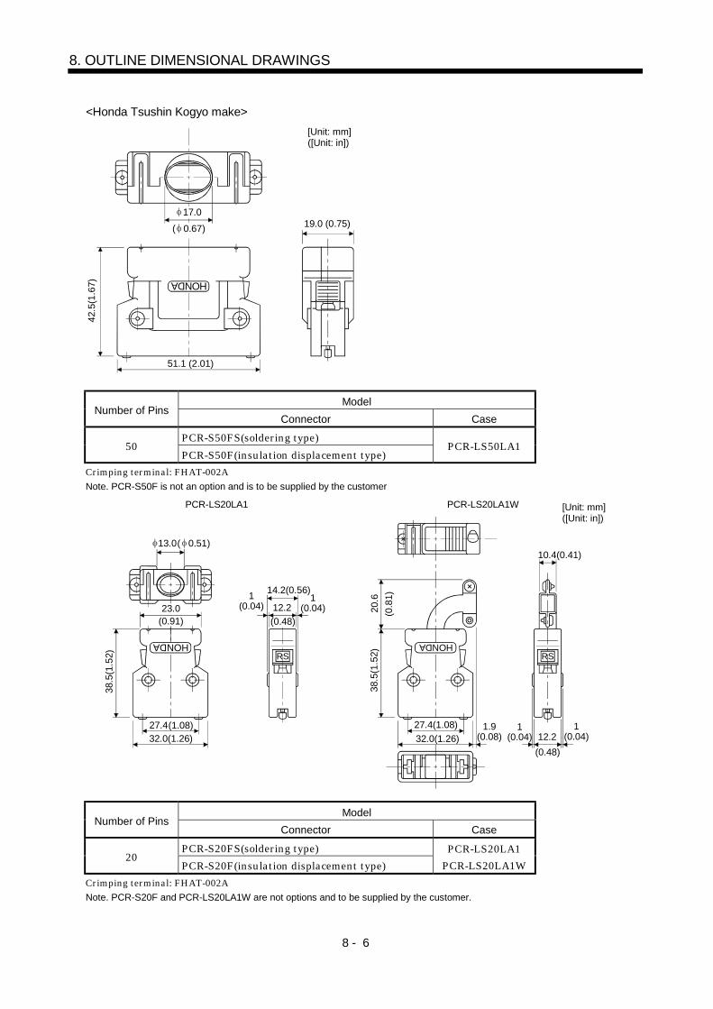
8 - 6
8. OUTLINE DIMENSIONAL DRAWINGS
<Honda Tsushin Kogyo make>
HONDA
[Unit: mm] ([Unit: in])
17.0( 0.67)
42.5
(1.6
7)
19.0 (0.75)
51.1 (2.01)
ModelNumber of Pins
Connector Case
PCR-S50FS(soldering type)50
PCR-S50F(insulation displacement type)PCR-LS50LA1
Crimping terminal: FHAT-002ANote. PCR-S50F is not an option and is to be supplied by the customer
38.5
(1.5
2)
27.432.0(1.26)
23.0
HONDA
13.0( 0.51)
1(0.04) 12.2
14.2(0.56)
(0.91)
(1.08)
1(0.04)
(0.48)
38.5
(1.5
2)
27.4(1.08)32.0(1.26)
HONDA
10.4(0.41)
1.9(0.08)
20.6
12.21
(0.04)1
(0.04)(0.48)
(0.8
1)
PCR-LS20LA1WPCR-LS20LA1 [Unit: mm] ([Unit: in])
RS RS
ModelNumber of Pins
Connector Case
PCR-S20FS(soldering type)20
PCR-S20F(insulation displacement type)PCR-LS20LA1
PCR-LS20LA1WCrimping terminal: FHAT-002ANote. PCR-S20F and PCR-LS20LA1W are not options and to be supplied by the customer.
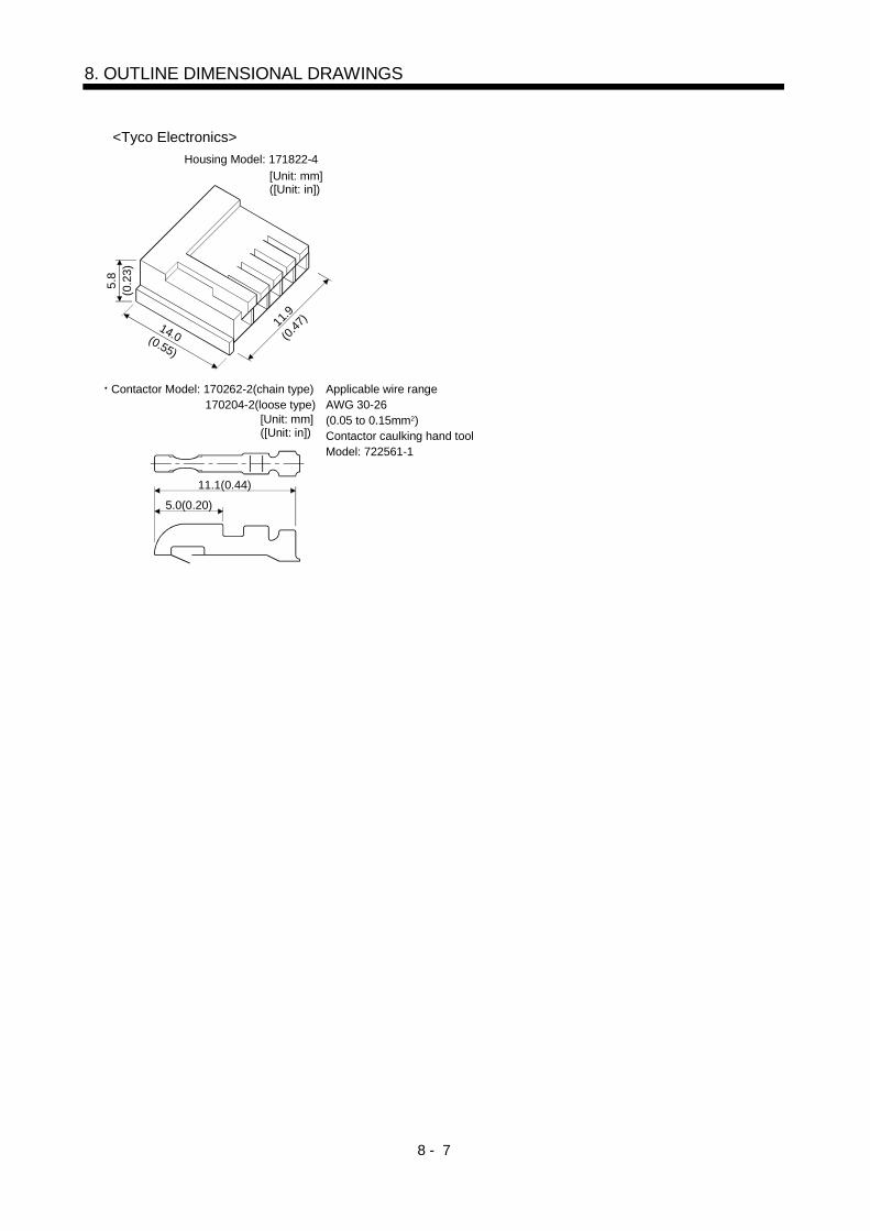
8 - 7
8. OUTLINE DIMENSIONAL DRAWINGS
5.8
(0.2
3)
14.0(0.55)
11.9
(0.47
)
Housing Model: 171822-4[Unit: mm] ([Unit: in])
<Tyco Electronics>
5.0(0.20)
11.1(0.44)
Applicable wire rangeAWG 30-26(0.05 to 0.15mm2)Contactor caulking hand toolModel: 722561-1
Contactor Model: 170262-2(chain type) 170204-2(loose type)
[Unit: mm] ([Unit: in])

8 - 8
8. OUTLINE DIMENSIONAL DRAWINGS
MEMO

9 - 1
9. CHARACTERISTICS
9. CHARACTERISTICS
9.1 Overload protection characteristics
An electronic thermal relay is built in the servo amplifier and converter unit to protect the servo motor,servo amplifier and converter unit from overloads.Overload 1 alarm (A.50) occurs if overload operation performed is above the electronic thermal relayprotection curve shown below. Overload 2 alarm (A.51) occurs if the maximum current flew continuouslyfor several seconds due to machine collision, etc. Use the equipment on the left-hand side area of thecontinuous or broken line in the graph.It is recommended to use the machine which generates unbalanced torque, e.g. a vertical lift application,so that the unbalanced torque is not more than 70% of the rated torque.
During servo lock
10000
1000
100
10
10 100
(90)200
(180)250
(225)
During rotation
(Note 1) Load ratio [%]
[s]
Ope
ratio
n tim
e
(Note 2)
Note 1. If operation that generates torque more than 100% of the rating is performed with an abnormally high frequency in a servomotor stop status (servo lock status) or in a 30r/min or less low-speed operation status, the servo amplifier may fail even whenthe electronic thermal relay protection is not activated.
2. The values within parentheses in the graph are those in the low acoustic noise mode of the MELSERVO-H series.
Fig 9.1 Electronic thermal relay protection characteristics

9 - 2
9. CHARACTERISTICS
9.2 Power supply equipment capacity and generated loss
(1) Power supply equipment capacity and generated lossTable 8.1 indicates the generated loss and power supply capacity under rated load per combination ofthe converter unit and servo amplifier. When the servo motors is run at less than the maximum speed,the power supply equipment capacity is lower than the value in the table but the heat generated doesnot change.Since the servo motor requires 2 to 2.5 times greater instantaneous power for acceleration, use thepower supply which ensures that the voltage lies within the permissible voltage fluctuation at themain circuit power supply terminals (L1, L2, L3) of the converter unit. The power supply equipmentcapacity changes with the power supply impedance.The actually generated heat falls within the ranges at rated torque and at zero torque according to thefrequencies of use during operation. When designing an enclosed control box, use the values in thetable, considering the worst operating conditions. The generated heat in Table 8.1 does not includeheat produced during regeneration.
Table 8.1 Power Supply Capacity and Generated Heat Per Servo Amplifier at Rated OutputPower SupplyCapacity [kVA]
(Note)Servo Amplifier-Generated Heart[W]
Area Required forHeat Dissipation
Servo Amplifier Converter UnitPowerfactor
improvingDC reactoris not used
Powerfactor
improvingDC reactor
is used
At rated torque At zero torque [m2] [ft2]
MR-JS-30KA/BMR-H30KAN/BN 48 40 1650
(1100 550)60
(30 30) 24.1 259.4
MR-JS-37KA/BMR-H37KAN/BN
MH-HP30KA59 49 1650
(1310 342)60
(30 30) 30.6 329.4
MR-JS-30KA4/B4MR-H30KAN4/BN4 48 40 1290
(1010 280)60
(30 30) 24.1 259.4
MR-JS-37KA4/B4MR-H37KAN4/BN4 59 49 1650
(1310 342)60
(30 30) 30.6 329.4
MR-JS-47KA4/B4MR-H47KAN4/BN4 71 59 1810
(1370 440)60
(30 30) 33.5 360.6
MR-JS-55KA4/B4MR-H55KAN4/BN4
MH-HP55KA4
87 72 2190(1690 500)
60(30 30) 40.5 435.9
Note. The heat generated by the servo amplifier is indicated in the left term within the parentheses, and the heat generated by theconverter unit in the right term.

9 - 3
9. CHARACTERISTICS
(2) Heat dissipation area of enclosed control boxWhen setting the temperature inside the enclosed control box (hereafter referred to as the control box)which will contain the converter unit and servo amplifier, factor in the allowance of about 5 (41 )relative to the maximum operating environmental condition temperature of 55 (131 ) so that it is amaximum of 10 (50 ) higher than the ambient temperature of 40 (104 ). Use Expression (9.1) tocalculate the heat dissipation area of the control box.
PA K T ...................................................................................................................................................... (9.1)
where, A : Heat dissipation area [m2]P : Loss generated in the control box [W]
T : Difference between internal and ambient temperatures [ ]K : Heat dissipation coefficient [5 to 6]
When calculating the heat dissipation area with Equation 9.1, assume that P is the sum of all lossesgenerated in the enclosure. Refer to Table 9.1 for heat generated by the servo amplifier. "A"indicates the effective area for heat dissipation, but if the enclosure is directly installed on aninsulated wall, that extra amount must be added to the enclosure's surface area.The required heat dissipation area will vary wit the conditions in the enclosure. If convection in theenclosure is poor and heat builds up, effective heat dissipation will not be possible. Therefore,arrangement of the equipment in the enclosure and the use of a fan should be considered.Table 8.1 lists the enclosure dissipation area for each servo amplifier when the servo amplifier isoperated at the ambient temperature of 40 (104 ) under rated load.
(Outside) (Inside)
Air flow
Fig 9.2 Temperature Distribution in Enclosure
When air flows along the outer wall of the enclosure, effective heat exchange will be possible,because the temperature slope inside and outside the enclosure will be steeper.
(3) Fitting of the servo amplifierWhen mounted with the heat sink outside mounting attachment (option), the servo amplifier candissipate generated loss directly to the outside of a control box. This method can reduce the heatdissipation area of the control box since 45 to 55% of the generated loss given in Table 9.1 is dissipatedto the outside of the enclosure. For details of the heat sink outside mounting attachment, refer toSection 10.3.2.

9 - 4
9. CHARACTERISTICS
9.3 Dynamic brake characteristics
Fig. 9.3 shows the pattern in which the servo motor comes to a stop when the dynamic brake is operated.Use Equation 9.2 to calculate an approximate coasting distance to a stop. The dynamic brake timeconstant t varies with the servo motor and machine operation speeds. (Refer to Fig. 9.4. Please contact usfor the servo motor not indicated.)
Emergency stop(EMG) OFF
ON
Machine speedV0
te
Time constant
Time
Fig 9.3 Dynamic Brake Operation Diagram
Lmax 60Vo JL
JMte 1 ....................................................................................................................... (9.2)
L max : Maximum coasting distance................................................................................................ [mm][in]V0 : Machine rapid feedrate......................................................................................... [mm/min][in/min]JM : Servo motor inertial moment ............................................................................... [kg cm2][oz in2]JL : Load inertia moment converted into equivalent value on servo motor shaft ... [kg cm2][oz in2]
: Brake time constant........................................................................................................................[s]te : Delay time of control section ..........................................................................................................[s]
(There is internal relay delay time of about 30ms.)
0 500 1000 1500 2000
0.04
0.03
0.02
0.01
0
Tim
e co
nsta
nt
0.005
0.015
0.025
0.035
0.045
Speed
HA-LF (S) 30K2
HA-LF (S) 37K2
HA-LF (S) 45K24
0 500 1000 1500 2000
0.04
0.03
0.02
0.01
0
Tim
e co
nsta
nt
0.005
0.015
0.025
0.035
0.045
HA-LF (S) 55K24
HA-LF (S) 37K24
HA-LF (S) 30K24
Speed
Fig 8.3 Dynamic Brake
If the dynamic brake is operated at more than 10 times as large as the ratio of load inertia moment toservo motor inertia moment, the brake resistor of the dynamic brake may burn out. If the value isexceeded, contacts us.
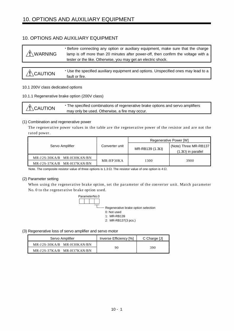
10 - 1
10. OPTIONS AND AUXILIARY EQUIPMENT
10. OPTIONS AND AUXILIARY EQUIPMENT
WARNINGBefore connecting any option or auxiliary equipment, make sure that the chargelamp is off more than 20 minutes after power-off, then confirm the voltage with atester or the like. Otherwise, you may get an electric shock.
CAUTION Use the specified auxiliary equipment and options. Unspecified ones may lead to afault or fire.
10.1 200V class dedicated options
10.1.1 Regenerative brake option (200V class)
CAUTION The specified combinations of regenerative brake options and servo amplifiersmay only be used. Otherwise, a fire may occur.
(1) Combination and regenerative powerThe regenerative power values in the table are the regenerative power of the resistor and are not therated power.
Regenerative Power [W]Servo Amplifier Converter unit
MR-RB139 (1.3 )(Note) Three MR-RB137
(1.3 ) in parallel
MR-J2S-30KA/B MR-H30KAN/BNMR-J2S-37KA/B MR-H37KAN/BN
MR-HP30KA 1300 3900
Note. The composite resistor value of three options is 1.3 . The resistor value of one option is 4 .
(2) Parameter settingWhen using the regenerative brake option, set the parameter of the converter unit. Match parameterNo. 0 to the regenerative brake option used.
ParameterNo.0
Regenerative brake option selection0: Not used1: MR-RB1392: MR-RB137(3 pcs.)
(3) Regenerative loss of servo amplifier and servo motor
Servo Amplifier Inverse Efficiency [%] C Charge [J]
MR-J2S-30KA/B MR-H30KAN/BNMR-J2S-37KA/B MR-H37KAN/BN
90 390

10 - 2
10. OPTIONS AND AUXILIARY EQUIPMENT
(4) Connection of the regenerative brake optionAlways supply single-phase 200VAC to the cooling fan. The cooling fan specifications are as follows.
Item Specifications
Voltage, frequency Single-phase 200VAC, 50/60HzPower consumption [W] 20(50Hz)/18(60Hz)
The regenerative brake option generates heat of 100 higher than the ambient temperature. Fullyconsider heat dissipation, installation position, used wires, etc. to place the option. For wiring, useflame-resistant wires or make the wires flame-resistant and keep them away from the regenerativebrake option. The G3 and G4 terminals act as a thermal sensor. G3-G4 are opened when theregenerative brake option overheats abnormally.Always twist the wires for connection with the converter unit and connect the wires within the overalldistance of 5m.
(a) MR-RB139
RAG4
Converter unit
P1P2
(Note1)
G3
P C
P C
OHS1 OHS2
R S
Single-phase 200VAC
24VDC power supply
Servo motor
Servo motor thermal relay
Regenerative brakeoption
(Note2)
Power factor improvingDC reactor (Option)
5m (16.4ft) or less
Note 1. When using the Power factor improving DC reactor, remove the short bar across P1-P2.2. G3-G4 contact specifications
Maximum voltage: 120V AC/DCMaximum current: 0.5V/4.8VDCMaximum capacity: 2.4VA
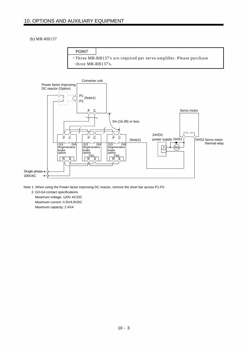
10 - 3
10. OPTIONS AND AUXILIARY EQUIPMENT
(b) MR-RB137
POINTThree MR-RB137's are required per servo amplifier. Please purchasethree MR-RB137's.
Converter unit
OHS1
R
Single-phase 200VAC
24VDC power supply
Servo motor
OHS2 Servo motor thermal relay
P1P2
P C
G4G3
P C
G4G3
P C
G4G3
P C
R SR SR S
(Note1)
Fan Fan
Regenerative brakeoption
Regenerative brakeoption
Regenerative brakeoption
RA
(Note2)
Power factor improvingDC reactor (Option)
5m (16.4ft) or less
Note 1. When using the Power factor improving DC reactor, remove the short bar across P1-P2.2. G3-G4 contact specifications
Maximum voltage: 120V AC/DCMaximum current: 0.5V/4.8VDCMaximum capacity: 2.4VA

10 - 4
10. OPTIONS AND AUXILIARY EQUIPMENT
(5) Outline dimension drawings
10(0.39)15
(0.59)230(9.06)
260(10.24)
TE1
480(
18.9
)
500(
19.6
9)
10(0
.39)
2.3(0.09)197(7.76)
215(8.47)
10(22.05)11(24.25)
TE1
Regenerative Brake Option
Mass[kg (lb)]
MR-RB139MR-RB137
R S G4 G3 C P
2- 10hole[Unit: mm] ([Unit: in])
10(0
.39)
15(0.59)
Terminal block signal layout
Terminal screw: M5Tightening torque: 2.0[N m] (17.7[lb in])
15(0.59)
Mounting screwScrew size: M8Tightening torque: 13.2[N m] (117[lb in])
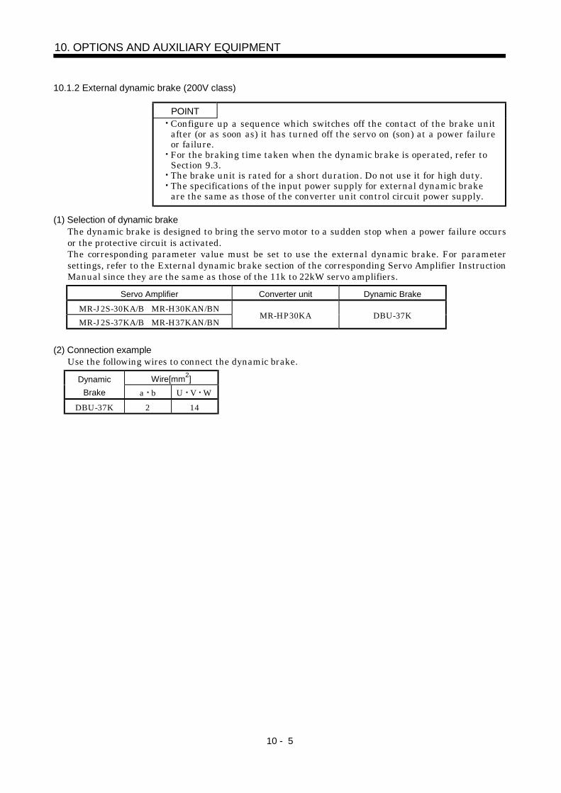
10 - 5
10. OPTIONS AND AUXILIARY EQUIPMENT
10.1.2 External dynamic brake (200V class)
POINTConfigure up a sequence which switches off the contact of the brake unitafter (or as soon as) it has turned off the servo on (son) at a power failureor failure.For the braking time taken when the dynamic brake is operated, refer toSection 9.3.The brake unit is rated for a short duration. Do not use it for high duty.The specifications of the input power supply for external dynamic brakeare the same as those of the converter unit control circuit power supply.
(1) Selection of dynamic brakeThe dynamic brake is designed to bring the servo motor to a sudden stop when a power failure occursor the protective circuit is activated.The corresponding parameter value must be set to use the external dynamic brake. For parametersettings, refer to the External dynamic brake section of the corresponding Servo Amplifier InstructionManual since they are the same as those of the 11k to 22kW servo amplifiers.
Servo Amplifier Converter unit Dynamic Brake
MR-J2S-30KA/B MR-H30KAN/BNMR-J2S-37KA/B MR-H37KAN/BN
MR-HP30KA DBU-37K
(2) Connection exampleUse the following wires to connect the dynamic brake.
Wire[mm2]DynamicBrake a b U V W
DBU-37K 2 14
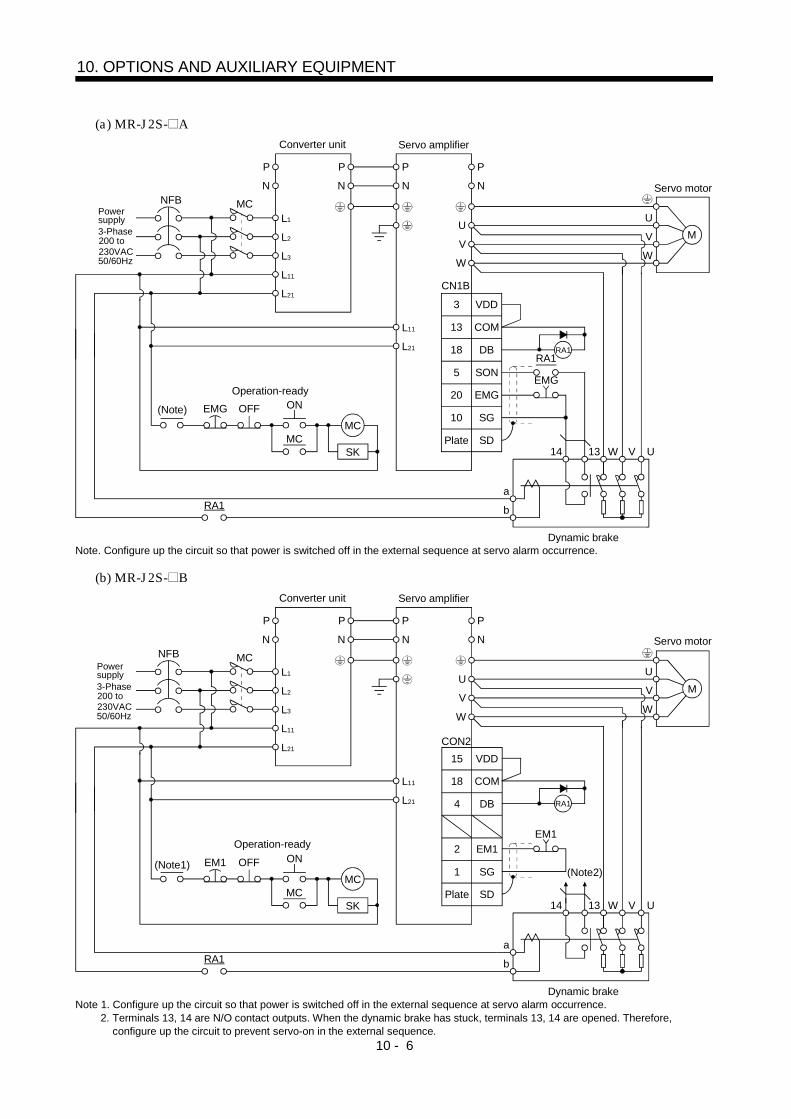
10 - 6
10. OPTIONS AND AUXILIARY EQUIPMENT
(a) MR-J2S- A
3-Phase200 to230VAC50/60Hz
Power supply
Converter unit Servo amplifier
Servo motor
Operation-ready
Dynamic brake
(Note)
NFB MC
RA1
L1
L2
L3
L11
L21
U
V
W
RA1
EMG
RA1
U
V
W
M
13 W14 V U
a
b
VDD3
COM13
DB18
SON5
EMG20
SG10
SDPlate
P
N
P
N
P
N
EMG OFF ON
MCMC
SK
L11
L21
P
N
CN1B
Note. Configure up the circuit so that power is switched off in the external sequence at servo alarm occurrence.
(b) MR-J2S- B
NFB MC
RA1
L1
L2
L3
L11
L21
U
V
W
EM1
RA1
U
V
W
M
13 W14 V U
a
b
P
N
P
N
P
N
EM1 OFF ON
MCMC
SK
L11
L21
P
N
CON2VDD15
COM18
DB4
EM12
SG1
SDPlate
Operation-ready
Dynamic brake
(Note1)
3-Phase200 to230VAC50/60Hz
Power supply
Converter unit Servo amplifier
Servo motor
(Note2)
Note 1. Configure up the circuit so that power is switched off in the external sequence at servo alarm occurrence.2. Terminals 13, 14 are N/O contact outputs. When the dynamic brake has stuck, terminals 13, 14 are opened. Therefore,
configure up the circuit to prevent servo-on in the external sequence.

10 - 7
10. OPTIONS AND AUXILIARY EQUIPMENT
(c) MR-H AN
NFB MC
RA1
L1
L2
L3
L11
L21
U
V
W
RA1
EMG
RA1
U
V
W
M
13 W14 V U
a
b
VDD22
VIN20
ALM48
SON12
EMG46
SG40
SD50
P
N
P
N
P
N
EMG OFF ON
MCMC
SK
L11
L21
P
N
CN1
Converter unit Servo amplifier
Servo motor
Operation-ready
3-Phase200 to230VAC50/60Hz
Power supply
(Note)
Dynamic brakeNote. Configure up the circuit so that power is switched off in the external sequence at servo alarm occurrence.
(d) MR-H BN
NFB MC
RA1
L1
L2
L3
L11
L21
U
V
W
EM1
RA1
U
V
W
M
13 W14 V U
a
b
COM3B
DB4A
EM11A
EM21B
P
N
P
N
P
N
EM1 OFF ON
MCMC
SK
L11
L21
P
N
CN6 DC24V
3-Phase200 to230VAC50/60Hz
Power supply
Converter unit Servo amplifier
Servo motor
Operation-ready
(Note1)(Note2)
Dynamic brakeNote 1. Configure up the circuit so that power is switched off in the external sequence at servo alarm occurrence.
2. Terminals 13, 14 are N/O contact outputs. When the dynamic brake has stuck, terminals 13, 14 are opened. Therefore,configure up the circuit to prevent servo-on in the external sequence.

10 - 8
10. OPTIONS AND AUXILIARY EQUIPMENT
(3) Operation timing
Servo motor rotation
Coasting
Alarm(ALM)
RA1
ON
OFF
Emergency stop(EMG)
Present
Absent
Invalid
Valid
Short
Open
a. Timing chart at alarm(ALM) occurrence b. Timing chart at emergency stop(EMG) validity
Dynamicbrake
Base
ON
OFF
Dynamic brake
Coasting
Dynamic brake
(4) Outline dimension drawing
230(9.06)
370(
14.5
7)10
(0.3
9)39
0(15
.35)
330(
12.9
9)30
(1.1
8)
10(0.39)
TE2 TE1
15(0.59)260(10.24) 235(9.25)
220(8.66)2.3(0.09)
U V Wa b1314
U
TE1
TE2
V W
a b 13 14
2- 10(0.39)Installation hole
Screw: M5
Screw: M3.5
30(1
.18)
10(0
.39)
15(0.59)
230(9.06) 15(0.59)15(0.59)
15(0.59)
[Unit: mm] ([Unit: in])
Tightening torque: 2.0[N m] (17.7[lb in])
Mass: 8[kg](17.64 [lb])
Tightening torque: 0.8[N m] (7.1[lb in])
Terminal
Screw size: M8Tightening torque: 13.2[N m] (117[lb in])
Mounting screw
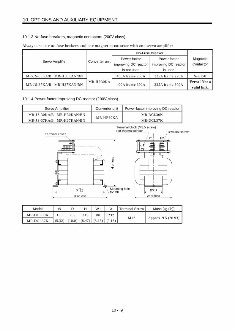
10 - 9
10. OPTIONS AND AUXILIARY EQUIPMENT
10.1.3 No-fuse breakers, magnetic contactors (200V class)
Always use one no-fuse brakers and one magnetic contactor with one servo amplifier.No-Fuse Breaker
Servo Amplifier Converter unitPower factor
improving DC reactoris not used
Power factorimproving DC reactor
is used
MagneticContactor
MR-JS-30KA/B MR-H30KAN/BN 400A frame 250A 225A frame 225A S-K150
MR-JS-37KA/B MR-H37KAN/BNMR-HP30KA
400A frame 300A 225A frame 300AError! Not a
valid link.
10.1.4 Power factor improving DC reactor (200V class)
Servo Amplifier Converter unit Power factor improving DC reactor
MR-JS-30KA/B MR-H30KAN/BN MR-DCL30KMR-JS-37KA/B MR-H37KAN/BN
MR-HP30KAMR-DCL37K
P1 P2
(W1)
Terminal cover
H o
r les
s
Mounting hole for M8
D or less
X
Terminal block (M3.5 screw)For thermal sensor Terminal screw
W or less
1.51.5
Model W D H W1 X Terminal Screw Mass [kg (lb)]
MR-DCL30KMR-DCL37K
135(5.32)
255(10.0)
215(8.47)
80(3.15)
232(9.13)
M12 Approx. 9.5 (20.93)

10 - 10
10. OPTIONS AND AUXILIARY EQUIPMENT
10.1.5 Radio noise filter (200V class)
Radio noise filter (FR-BIF) is effective in suppressing noises radiated from the power supply side ofthe servo amplifier especially in 10MHz and lower radio frequency bands. The radio noise filter isdesigned for the input only.
Connection diagram Outline drawing (Unit: mm) ([Unit: in.])Make the connection cables as short as possible.Grounding is always required.When using the FR-BIF with a single-phase wire, always insulate the pins that are not used for wiring.
Converter unitNFB
L3
L2
L1
MC
Powersupply
Radio noise filter FR-BIF
Leakage current: 4mA
29 (1.14)
58 (2.28)
42 (1
.65)
4 (0
.16)
Red BlueWhite Green
44 (1.73)
29 (1.14) 7 (0.28)
holeAb
out 3
00(1
1.81
)
5 (0.20)

10 - 11
10. OPTIONS AND AUXILIARY EQUIPMENT
10.2 400V class dedicated options
10.2.1 Regenerative brake option (400V class)
CAUTION The specified combinations of regenerative brake options and servo amplifiersmay only be used. Otherwise, a fire may occur.
(1) Combination and regenerative powerThe regenerative power values in the table are the regenerative power of the resistor and are not therated power.
Regenerative Power [W]Servo Amplifier Converter unit
MR-RB136-4 (5 )(Note) Three MR-RB138-4
(5 ) in parallelMR-JS-30KA4/B4 MR-H30KAN4/BN4MR-JS-37KA4/B4 MR-H37KAN4/BN4MR-JS-45KA4/B4 MR-H45KAN4/BN4MR-JS-55KA4/B4 MR-H55KAN4/BN4
MR-HP55KA4 1300 3900
Note. The composite resistor value of three options is 5 .
(2) Parameter settingWhen using the regenerative brake option, set the parameter of the converter unit. Match parameterNo. 0 to the regenerative brake option used.
ParameterNo.0
Regenerative brake option selection0: Not used1: MR-RB136-42: MR-RB138-4(3 pcs.)
(3) Regenerative loss of servo amplifier and servo motorServo Amplifier Inverse Efficiency [%] C Charge [J]
MR-JS-30KA4/B4 MR-H30KAN4/BN4 90 310MR-JS-37KA4/B4 MR-H37KAN4/BN4 90 370MR-JS-45KA4/B4 MR-H45KAN4/BN4 90 450MR-JS-55KA4/B4 MR-H55KAN4/BN4 90 450

10 - 12
10. OPTIONS AND AUXILIARY EQUIPMENT
(4) Connection of the regenerative brake optionAlways supply single-phase 400VAC to the cooling fan. The cooling fan specifications are as follows.
Item Specifications
Voltage, frequency Single-phase 400VAC, 50/60HzPower consumption [W] 20(50Hz)/18(60Hz)
The regenerative brake option generates heat of 100 higher than the ambient temperature. Fullyconsider heat dissipation, installation position, used wires, etc. to place the option. For wiring, useflame-resistant wires or make the wires flame-resistant and keep them away from the regenerativebrake option. The G3 and G4 terminals act as a thermal sensor. G3-G4 are opened when theregenerative brake option overheats abnormally.Always twist the wires for connection with the converter unit and connect the wires within the overalldistance of 5m.
(a) MR-RB136-4
RAG4
Converter unit
P1P2
(Note1)
G3
P C
P C
OHS1 OHS2
R400 S400
Single-phase 400VAC
24VDC power supply
Servo motor
Servo motor thermal relay
Regenerative brakeoption
Fan
(Note2)
Power factor improvingDC reactor (Option)
5m (16.4ft) or less
Note 1. When using the Power factor improving DC reactor, remove the short bar across P1-P2.2. G3-G4 contact specifications
Maximum voltage: 120V AC/DCMaximum current: 0.5V/4.8VDCMaximum capacity: 2.4VA
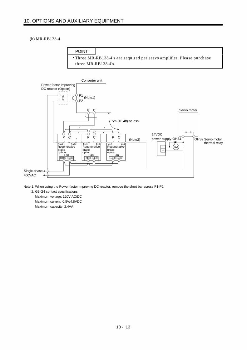
10 - 13
10. OPTIONS AND AUXILIARY EQUIPMENT
(b) MR-RB138-4
POINTThree MR-RB138-4's are required per servo amplifier. Please purchasethree MR-RB138-4's.
Converter unit
OHS1
R
Single-phase 400VAC
24VDC power supply
Servo motor
OHS2 Servo motor thermal relay
Rrgeneative brakeoption
P1P2
P C
G4G3
P C
G4G3
P C
G4G3
P C
R400 S400R400 S400R400 S400
(Note1)
Fan Fan
Regenerative brakeoption
Regenerative brakeoption
Regenerative brakeoption
RA
Fan
(Note2)
Power factor improvingDC reactor (Option)
5m (16.4ft) or less
Note 1. When using the Power factor improving DC reactor, remove the short bar across P1-P2.2. G3-G4 contact specifications
Maximum voltage: 120V AC/DCMaximum current: 0.5V/4.8VDCMaximum capacity: 2.4VA

10 - 14
10. OPTIONS AND AUXILIARY EQUIPMENT
(5) Outline dimension drawings
10(0.39)15
(0.59)230(9.06)
260(10.24)
TE1
480(
18.9
)
500(
19.6
9)
10(0
.39)
2.3(0.09)197(7.76)
215(8.47)
10(22.05)11(24.25)
TE1
Regenerative Brake Option
Mass[kg (lb)]
MR-RB136-4MR-RB138-4
R400 S400 G4 G3 C P
2- 10hole[Unit: mm] ([Unit: in])
10(0
.39)
15(0.59)
Terminal block signal layout
15(0.59)
Terminal screw: M5Tightening torque: 2.0[N m] (17.7[lb in])
Mounting screwScrew size: M8Tightening torque: 13.2[N m] (117[lb in])

10 - 15
10. OPTIONS AND AUXILIARY EQUIPMENT
10.2.2 External dynamic brake (400V class)
POINTConfigure up a sequence which switches off the contact of the brake unitafter (or as soon as) it has turned off the servo on (son) at a power failureor failure.For the braking time taken when the dynamic brake is operated, refer toSection 9.3.The brake unit is rated for a short duration. Do not use it for high duty.The specifications of the input power supply for external dynamic brakeare the same as those of the converter unit control circuit power supply.
(1) Selection of dynamic brakeThe dynamic brake is designed to bring the servo motor to a sudden stop when a power failure occursor the protective circuit is activated.The corresponding parameter value must be set to use the external dynamic brake. For parametersettings, refer to the External dynamic brake section of the corresponding Servo Amplifier InstructionManual since they are the same as those of the 11k to 22kW servo amplifiers.
Servo Amplifier Converter unit Dynamic BrakeMR-JS-30KA4/B4 MR-H30KAN4/BN4MR-JS-37KA4/B4 MR-H37KAN4/BN4MR-JS-45KA4/B4 MR-H45KAN4/BN4MR-JS-55KA4/B4 MR-H55KAN4/BN4
MR-HP55KA4 DBU-55K-4
(2) Connection exampleUse the following wires to connect the dynamic brake.
Wire[mm2]DynamicBrake a b U V W
DBU-55K-4 2 14

10 - 16
10. OPTIONS AND AUXILIARY EQUIPMENT
(a) MR-J2S- A4
NFB MC
RA1
L1
L2
L3
L11
L21
U
V
W
RA1
EMG
RA1
U
V
W
M
13 W14 V U
a
b
P
N
P
N
P
N
EMG OFF ON
MCMC
SK
L11
L21
P
N
Step- down trans- former
VDD3
COM13
DB18
SON5
EMG20
SG10
SDPlate
CN1B
3-Phase380 to480VAC50/60Hz
Power supply
Converter unit Servo amplifier
Servo motor
Operation-ready
Dynamic brake
(Note)
Note. Configure up the circuit so that power is switched off in the external sequence at servo alarm occurrence.
(b) MR-J2S- B4
NFB MCL1
L2
L3
L11
L21
U
V
W
RA1
U
V
W
M
13 W V U
a
b
P
N
P
N
P
N
EM1 OFF ON
MCMC
SK
L11
L21
P
N
RA1
EM1
14
CON2VDD15
COM18
DB4
EM12
SG1
SDPlate
3-Phase380 to480VAC50/60Hz
Power supply
Operation-ready
Dynamic brake
(Note1)
Step- down trans- former
(Note2)
Converter unit Servo amplifier
Servo motor
Note 1. Configure up the circuit so that power is switched off in the external sequence at servo alarm occurrence.2. Terminals 13, 14 are N/O contact outputs. When the dynamic brake has stuck, terminals 13, 14 are opened. Therefore,
configure up the circuit to prevent servo-on in the external sequence.

10 - 17
10. OPTIONS AND AUXILIARY EQUIPMENT
(c) MR-H AN4
NFB MC
RA1
L1
L2
L3
L11
L21
U
V
W
RA1
EMG
RA1
U
V
W
M
13 W14 V U
a
b
P
N
P
N
P
N
EMG OFF ON
MCMC
SK
L11
L21
P
N
VDD22
VIN20
ALM48
SON12
EMG46
SG40
SD50
CN1
Step- down trans- former
Converter unit Servo amplifier
Servo motor
Operation-ready
Dynamic brake
(Note)
3-Phase380 to480VAC50/60Hz
Power supply
Note. Configure up the circuit so that power is switched off in the external sequence at servo alarm occurrence.
(d) MR-H BN4
NFB MCL1
L2
L3
L11
L21
U
V
W
RA1
U
V
W
M
13 W V U
a
b
P
N
P
N
P
N
EM1 OFF ON
MCMC
SK
L11
L21
P
N
RA1
EM1
14
COM3B
DB4A
EM11A
EM21B
CN6 DC24V
Step- down trans- former
3-Phase380 to480VAC50/60Hz
Power supply
Converter unit Servo amplifier
Servo motor
Operation-ready
Dynamic brake
(Note1)(Note2)
Note 1. Configure up the circuit so that power is switched off in the external sequence at servo alarm occurrence.2. Terminals 13, 14 are N/O contact outputs. When the dynamic brake has stuck, terminals 13, 14 are opened. Therefore,
configure up the circuit to prevent servo-on in the external sequence.

10 - 18
10. OPTIONS AND AUXILIARY EQUIPMENT
(3) Operation timing
Servo motor rotation
Coasting
Alarm(ALM)
RA1
ON
OFF
Emergency stop(EMG)
Present
Absent
Invalid
Valid
Short
Open
a. Timing chart at alarm(ALM) occurrence b. Timing chart at emergency stop(EMG) validity
Dynamicbrake
Base
ON
OFF
Dynamic brake
Coasting
Dynamic brake
(4) Outline dimension drawing
230(9.06)
370(
14.5
7)10
(0.3
9)39
0(15
.35)
330(
12.9
9)30
(1.1
8)
10(0.39)
TE2 TE1
15(0.59)260(10.24) 235(9.25)
220(8.66)2.3(0.09)
U V Wa b1314
TE1
2- 10(0.39)Installation hole
30(1
.18)
10(0
.39)
15(0.59)
230(9.06) 15(0.59)15(0.59)
15(0.59)
[Unit: mm] ([Unit: in])
Mass: 11[kg](24.25 [lb])
U
TE2
V W
a b 13 14
Screw: M5
Screw: M3.5
Tightening torque: 2.0[N m] (17.7[lb in])
Tightening torque: 0.8[N m] (7.1[lb in])
Terminal
Screw size: M8Tightening torque: 13.2[N m] (117[lb in])
Mounting screw

10 - 19
10. OPTIONS AND AUXILIARY EQUIPMENT
10.2.3 No-fuse breakers, magnetic contactors (400V class)
Always use one no-fuse brakers and one magnetic contactor with one servo amplifier.No-Fuse Breaker
Servo Amplifier Converter unitPower factor
improving DC reactoris not used
Power factorimproving DC reactor
is used
MagneticContactor
MR-JS-30KA4/B4 MR-H30KAN4/BN4 225A frame 150A 225A frame 125A S-K95MR-JS-37KA4/B4 MR-H37KAN4/BN4 225A frame 175A 225A frame 150A S-K125MR-JS-45KA4/B4 MR-H45KAN4/BN4 225A frame 225A 225A frame 175A S-K150MR-JS-55KA4/B4 MR-H55KAN4/BN4
MR-HP55KA4
400A frame 250A 225A frame 225A S-K180
10.2.4 Power factor improving DC reactor (400V class)
Servo Amplifier Converter unit Power factor improving DC reactorMR-JS-30KA4/B4 MR-H30KAN4/BN4 MR-DCL30K-4MR-JS-37KA4/B4 MR-H37KAN4/BN4 MR-DCL37K-4MR-JS-45KA4/B4 MR-H45KAN4/BN4 MR-DCL45K-4MR-JS-55KA4/B4 MR-H55KAN4/BN4
MR-HP55KA4
MR-DCL55K-4
P1 P2
1.5 1.5 (W1)
Terminal cover
H o
r les
s
Mounting hole for M8
D or less
X
Terminal block (M3.5 screw)For thermal sensor Terminal screw
W or less
[Unit: mm] ([Unit: in])
Model W D H W1 X Terminal Screw Mass [kg (Ib)]
MR-DCL30K-4 135(5.32) 205(8.07) 200(7.87) 75(2.95) 175(6.89) M8 Approx. 6.5(14.32)MR-DCL37K-4 135(5.32) 225(8.86) 200(7.87) 80(3.15) 197(7.76) M8 Approx. 7(15.42)MR-DCL45K-4 135(5.32) 240(9.45) 200(7.87) 80(3.15) 212(8.35) M8 Approx. 7.5(16.52)MR-DCL55K-4 135(5.32) 260(10.24) 215(8.47) 80(3.15) 232(9.13) M8 Approx. 9.5(20.93)
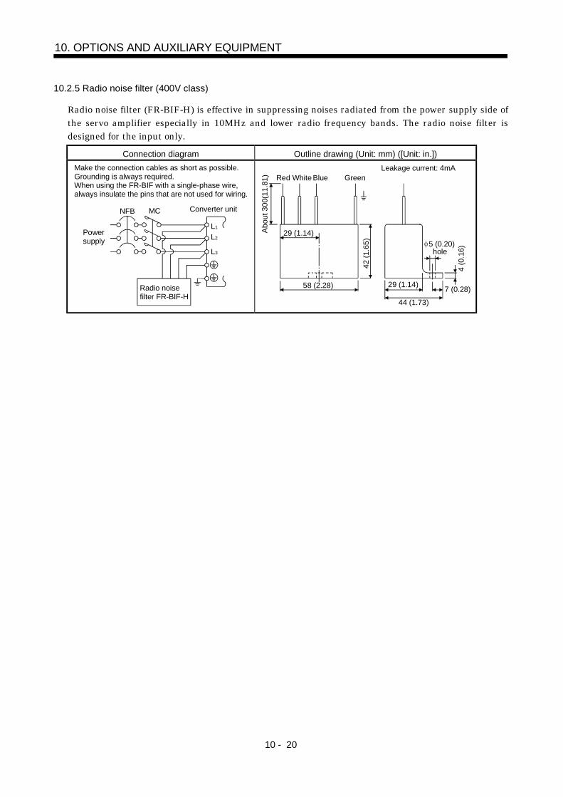
10 - 20
10. OPTIONS AND AUXILIARY EQUIPMENT
10.2.5 Radio noise filter (400V class)
Radio noise filter (FR-BIF-H) is effective in suppressing noises radiated from the power supply side ofthe servo amplifier especially in 10MHz and lower radio frequency bands. The radio noise filter isdesigned for the input only.
Connection diagram Outline drawing (Unit: mm) ([Unit: in.])Make the connection cables as short as possible.Grounding is always required.When using the FR-BIF with a single-phase wire, always insulate the pins that are not used for wiring.
Converter unitNFB
L3
L2
L1
MC
Powersupply
Radio noise filter FR-BIF-H
Leakage current: 4mA
29 (1.14)
58 (2.28)
42 (1
.65)
4 (0
.16)
Red BlueWhite Green
44 (1.73)
29 (1.14) 7 (0.28)
holeAb
out 3
00(1
1.81
)
5 (0.20)
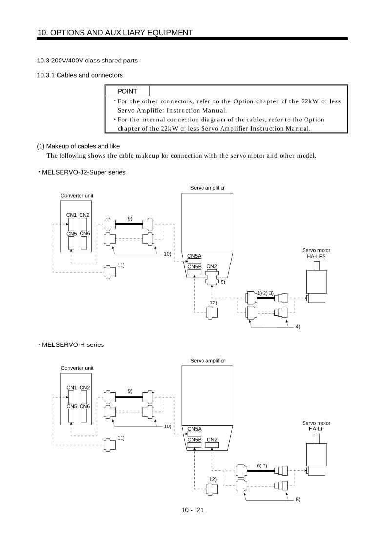
10 - 21
10. OPTIONS AND AUXILIARY EQUIPMENT
10.3 200V/400V class shared parts
10.3.1 Cables and connectors
POINTFor the other connectors, refer to the Option chapter of the 22kW or lessServo Amplifier Instruction Manual.For the internal connection diagram of the cables, refer to the Optionchapter of the 22kW or less Servo Amplifier Instruction Manual.
(1) Makeup of cables and likeThe following shows the cable makeup for connection with the servo motor and other model.
MELSERVO-J2-Super series
CN5A
CN5B CN2
CN6CN5
CN2CN1
Servo motorHA-LFS
Converter unitServo amplifier
9)
10)
11)
5)
12)
1) 2) 3)
4)
MELSERVO-H series
CN5A
CN5B CN2
CN6CN5
CN2CN1
Servo motorHA-LF
Converter unitServo amplifier
9)
10)
11)
12)
8)
6) 7)

10 - 22
10. OPTIONS AND AUXILIARY EQUIPMENT
No. Product Name Model Description Application1) Standard
encoder cableMR-JHSCBL M-L Connector: 10120-3000VE
Shell kit: 10320-52F0-008(3M or equivalent)
Connector: MS3106B20-29SCable clamp: MS3057-12A(DDK)
Standardflexing lifeIP20
2) Long flexinglife encodercable
MR-JHSCBL M-H Long flexinglife
Connector: 10120-3000VEShell kit: 10320-52F0-008(3M or equivalent)
Connector: MS3106A20-29S (D190)
Cable clamp: CE3057-12A-3 (D265)
Back shell: CE02-20BS-S(DDK)
3) IP65-compliantencoder cable
MR-ENCBL M-H Long flexinglifeIP65IP67Not oil-resistant.
Connector: 10120-3000VEShell kit: 10320-52F0-008(3M or equivalent)
Connector: MS3106B20-29SCable clamp: MS3057-12A(DDK)
4) Encoderconnector set
MR-J2CNS IP20
5) Conversionconnector
MR-HCN2 Provided for the MELSERVO-J2-Super servo amplifier.
6) Encoder cable MR-HSCBL M Servo amplifier side connector(Honda Tsushin Kogyo make)Connector: PCR-S20FSCable: PCR-LS20LA1
Encoder side connector(DDK)Plug: MS3106B20-29SCable clamp: MS-3057-12A
Long flexinglifeIP22
Servo amplifier side connector(Honda Tsushin Kogyo)Connector: PCR-S20FSCable: PCR-LS20LA1
Encoder side connector(DDK)Plug: MS3106A20-29S(D190)Cable clamp: CE-3057-12A-3(D265)Back shell: CE02-20BS-S
7) Encoder cable MR-EN1CBL M-H Long flexinglifeIP65compliant
8) Encoderconnector set
MR-JSCNS Servo amplifier side connector(Honda Tsushin Kogyo make)Connector: PCR-S20FSCable: PCR-LS20LA1
Encoder side connector(DDK)Plug: MS3106B20-29SCable clamp: MS3057-12A
IP22
9) Bus cable MR-J2HBUS M 3M make or equivalentConnector: 10120-3000VEShell kit: 10320-52F0-008
3M make or equivalentConnector: 10120-3000VEShell kit: 10320-52F0-008
10) Control signalconnector set
MR-J2CN1 Servo amplifier side connectors(3M make or equivalent)Connector: 10120-3000VEShell kit: 10320-52F0-008
11) Connector set MR-HP4CN1 Converter unit side connector(3M make or equivalent)Connector: 10114-3000VEShell kit: 10314-52F0-008
12) Terminationconnector
MR-A-TM
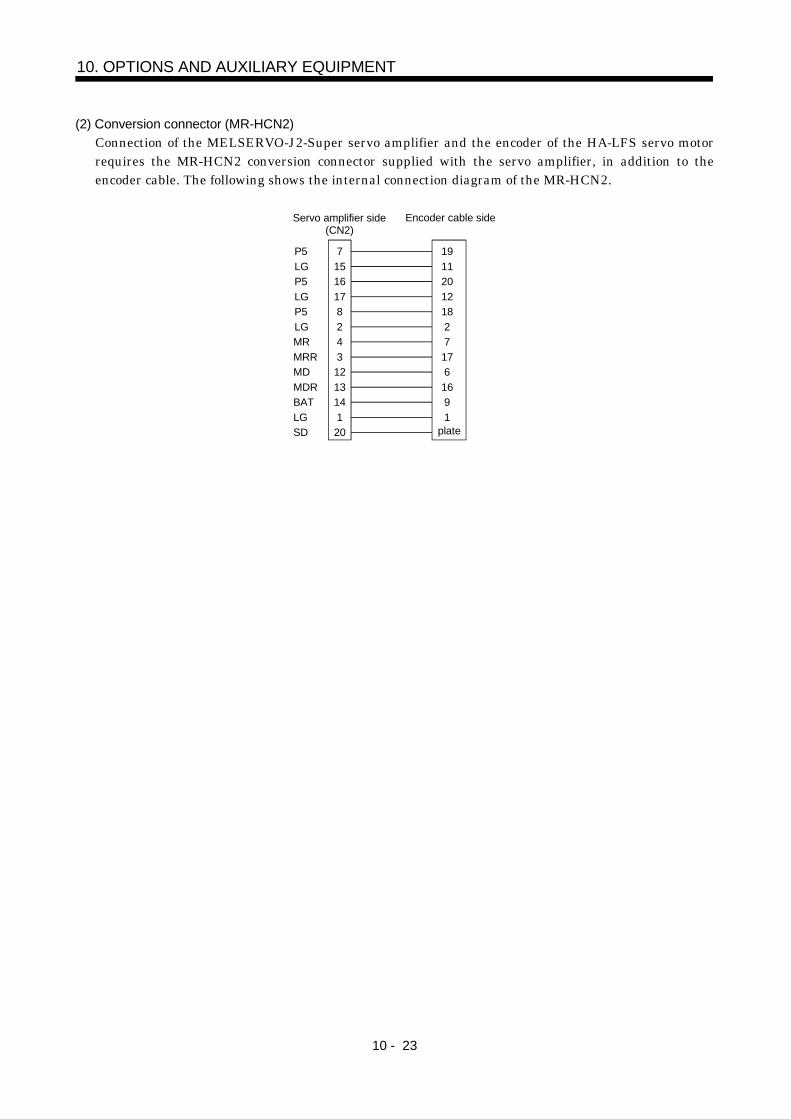
10 - 23
10. OPTIONS AND AUXILIARY EQUIPMENT
(2) Conversion connector (MR-HCN2)Connection of the MELSERVO-J2-Super servo amplifier and the encoder of the HA-LFS servo motorrequires the MR-HCN2 conversion connector supplied with the servo amplifier, in addition to theencoder cable. The following shows the internal connection diagram of the MR-HCN2.
P5LGP5LG
7151617
MRMRR
82
34
LG
13BAT
12
SD
19112012
717
218
166
19
P5LG
MDMDR
114
20
Servo amplifier side(CN2)
Encoder cable side
plate

10 - 24
10. OPTIONS AND AUXILIARY EQUIPMENT
10.3.2 Heat sink outside mounting attachment (MR-ACN)
Use the heat sink outside mounting attachment to mount the heat generation area of the servo amplifierin the outside of the control box to dissipate servo amplifier-generated heat to the outside of the box andreduce the amount of heat generated in the box, thereby allowing a compact control box to be designed.In the control box, machine a hole having the panel cut dimensions, fit the heat sink outside mountingattachment to the servo amplifier with the fitting screws (4 screws supplied), and install the servoamplifier to the control box.The environment outside the control box when using the heat sink outside mounting attachment shouldbe within the range of the servo amplifier operating environment conditions.
(1) Panel cut dimensions[Unit : mm(in)]
Variable DimensionsConverter unit/Servo amplifier
AttachmentA B C D
MR-HP30KA MR-ACNP55K 156(6.16)
110(4.33)
205(8.09)
190(7.48)
MR-JS-30KA/B MR-H30KAN/BNMR-JS-37KA/B MR-H37KAN/BN
MR-ACN55K 406(15.98)
360(14.17)
455(17.91)
440(17.32)
Variable DimensionsConverter unit/Servo amplifier
AttachmentA B C D
MR-HP55KA4 MR-ACNP55K 156(6.16)
110(4.33)
205(8.09)
190(7.48)
MR-JS-30KA4/B4 MR-H30KAN4/BN4 MR-ACN30K 336(13.23)
290(11.42)
385(15.16)
370(14.57)
MR-JS-37KA4/B4 MR-H37KAN4/BN4
MR-JS-45KA4/B4 MR-H45KAN4/BN4
B
CA
15
D
4-M10 Screw
605(
23.8
2)57
5(22
.64)
444(
17.4
8)(0
.59)
MR-JS-55KA4/B4 MR-H55KAN4/BN4
MR-ACN55K 406(15.98)
360(14.17)
455(17.91)
440(17.32)
(2) Fitting method
Attachment
a. Assembling the heat sink outside mounting attachment b. Installation to the control box
control box
Attachment supplied tothe servo amplifier(Note)
Note. Remove the attachment supplied and fit it in the specified position.
Square hole
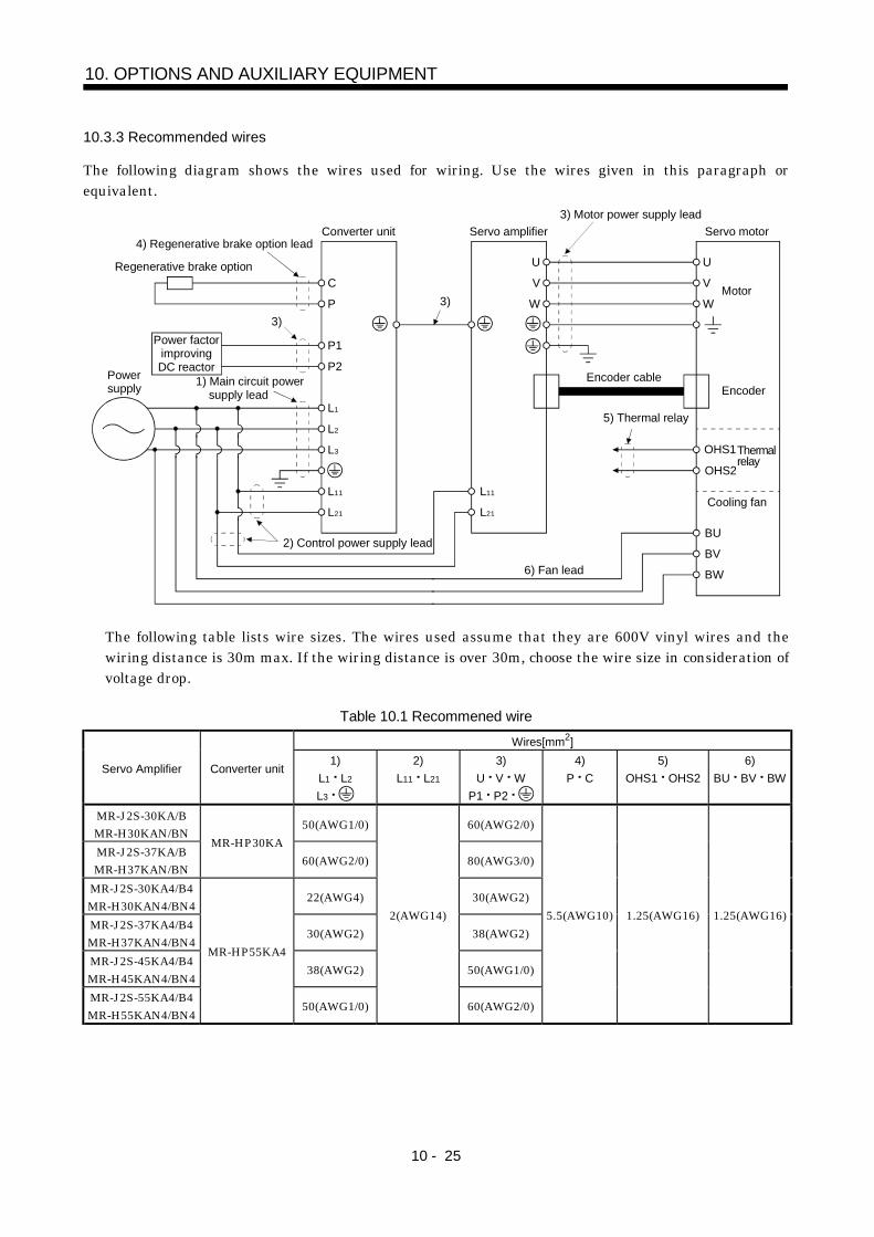
10 - 25
10. OPTIONS AND AUXILIARY EQUIPMENT
10.3.3 Recommended wires
The following diagram shows the wires used for wiring. Use the wires given in this paragraph orequivalent.
C
P
P1
P2
L1
L2
L3
L11
L21
V
U
W
V
U
W
OHS2
BU
BV
BW
L11
L21
Converter unit
Powersupply
Servo amplifier Servo motor
Encoder
Motor
3) Motor power supply lead
Regenerative brake option
3)
2) Control power supply lead
Encoder cable
Cooling fan
1) Main circuit power supply lead
6) Fan lead
5) Thermal relay
OHS1Thermal relay
4) Regenerative brake option lead
3)Power factor
improvingDC reactor
The following table lists wire sizes. The wires used assume that they are 600V vinyl wires and thewiring distance is 30m max. If the wiring distance is over 30m, choose the wire size in consideration ofvoltage drop.
Table 10.1 Recommened wireWires[mm2]
Servo Amplifier Converter unit1)
L1 L2
L3
2)L11 L21
3)U V W
P1 P2
4)P C
5)OHS1 OHS2
6)BU BV BW
MR-J2S-30KA/BMR-H30KAN/BN 50(AWG1/0) 60(AWG2/0)
MR-J2S-37KA/BMR-H37KAN/BN
MR-HP30KA60(AWG2/0) 80(AWG3/0)
MR-J2S-30KA4/B4MR-H30KAN4/BN4 22(AWG4) 30(AWG2)
MR-J2S-37KA4/B4MR-H37KAN4/BN4 30(AWG2) 38(AWG2)
MR-J2S-45KA4/B4MR-H45KAN4/BN4 38(AWG2) 50(AWG1/0)
MR-J2S-55KA4/B4MR-H55KAN4/BN4
MR-HP55KA4
50(AWG1/0)
2(AWG14)
60(AWG2/0)
5.5(AWG10) 1.25(AWG16) 1.25(AWG16)
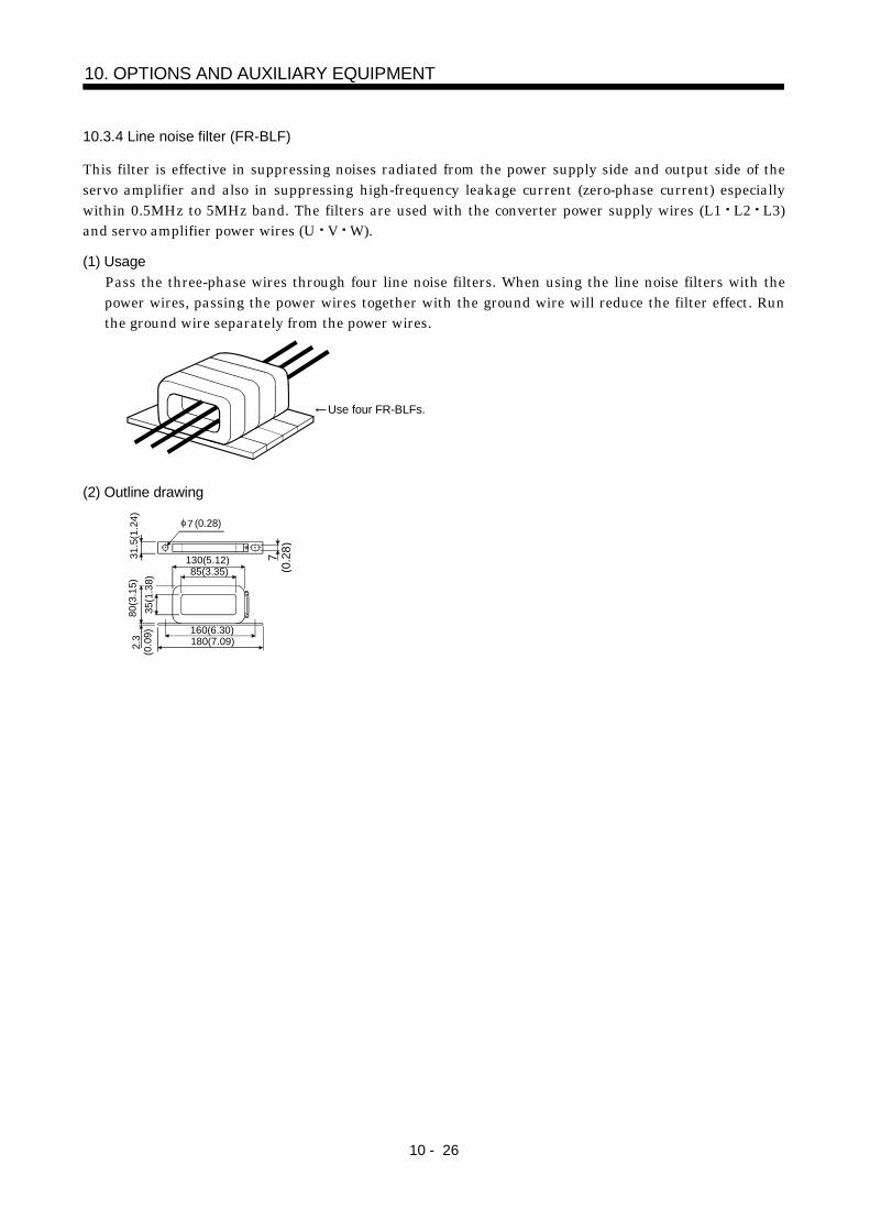
10 - 26
10. OPTIONS AND AUXILIARY EQUIPMENT
10.3.4 Line noise filter (FR-BLF)
This filter is effective in suppressing noises radiated from the power supply side and output side of theservo amplifier and also in suppressing high-frequency leakage current (zero-phase current) especiallywithin 0.5MHz to 5MHz band. The filters are used with the converter power supply wires (L1 L2 L3)and servo amplifier power wires (U V W).
(1) UsagePass the three-phase wires through four line noise filters. When using the line noise filters with thepower wires, passing the power wires together with the ground wire will reduce the filter effect. Runthe ground wire separately from the power wires.
Use four FR-BLFs.
(2) Outline drawing
160(6.30)180(7.09)
130(5.12)85(3.35)
2.3
(0.0
9)31
.5(1
.24)
7(0
.28)
7 (0.28)
35(1
.38)
80(3
.15)

10 - 27
10. OPTIONS AND AUXILIARY EQUIPMENT
10.3.5 Leakage current breaker
(1) Selection methodHigh-frequency chopper currents controlled by pulse width modulation flow in the AC servo circuits.Leakage currents containing harmonic contents are larger than those of the motor which is run with acommercial power supply.Select a leakage current breaker according to the following formula, and ground the servo amplifier,servo motor, etc. securely.Make the input and output cables as short as possible, and also make the grounding cable as long aspossible (about 30cm (11.8 in)) to minimize leakage currents.
Rated sensitivity current 10 {Ig1 Ign Iga K (Ig2 Igm)} [mA] ................................................ (10.1)K: Constant considering the harmonic contents
Leakage current breaker
TypeMitsubishiproducts
K
Models provided withharmonic and surgereduction techniques
NV-SPNV-SWNV-CPNV-CWNV-HW
1
General modelsBV-C1NFBNV-L
3
M
Noise filterCable
NV
Ig1 Ign Ig2 IgmIga
CableServoamplifier
Converterunit
Ig1: Leakage current on the electric channel from the leakage current breaker to the input terminalsof the servo amplifier (Found from Fig. 10.1.)
Ig2: Leakage current on the electric channel from the output terminals of the servo amplifier to the servo motor (Found from Fig. 10.1.)
Ign: Leakage current when a filter is connected to the input side (4.4mA per one FR-BIF or FR-BIF-H)Iga: Leakage current of the servo amplifier (Found from Table 10.3.)Igm: Leakage current of the servo motor (Found from Table 10.2.)
Table 10.2 Servo Motor’s Leakage Current Example (lgm)Table 10.3 Converter Unit
Servo Amplifier's LeakageCurrent Example (Iga)
Servo Motor Output[kW]
LeakageCurrent[mA]
Converter UnitServo Amplifier
LeakageCurrent[mA]
30 to 55 2.5 All series 5120
100
80
60
40
20
02 3.5
5.58 14 2238 80150
3060 100
Cable size[mm2]
[mA]
Leak
age
curre
nt
a) 200V class
120100806040200 2
3.55.5
814
2238
80150
3060
100
Cable size [mm2]
[mA]
Leak
age
curre
nt
b) 400V class
Fig.10.1 Leakage Current Example (lg1, lg2) for CV Cable Run in Metal Conduit
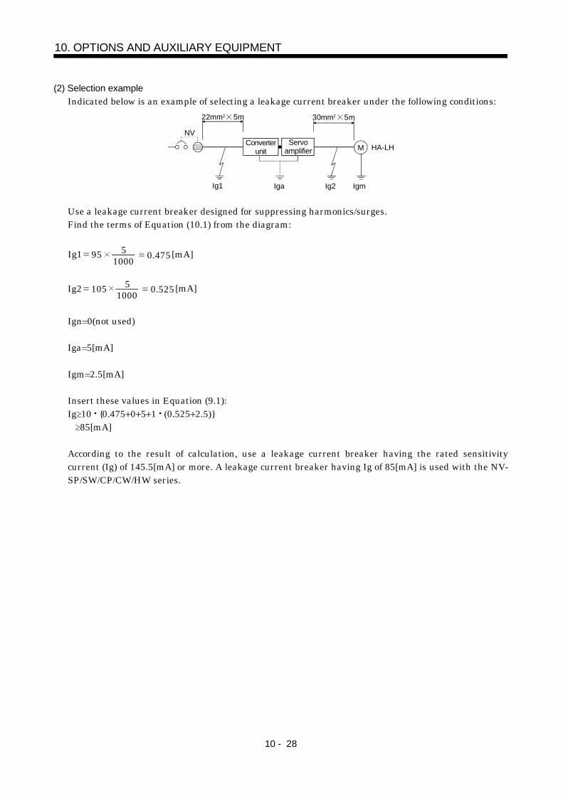
10 - 28
10. OPTIONS AND AUXILIARY EQUIPMENT
(2) Selection exampleIndicated below is an example of selecting a leakage current breaker under the following conditions:
M HA-LH
30mm2 5m22mm2 5m
Ig1 Ig2Iga Igm
NVServo
amplifierConverter
unit
Use a leakage current breaker designed for suppressing harmonics/surges.Find the terms of Equation (10.1) from the diagram:
Ig1 95 10005 0.475[mA]
Ig2 105 10005 0.525[mA]
Ign 0(not used)
Iga 5[mA]
Igm 2.5[mA]
Insert these values in Equation (9.1):Ig 10 {0.475 0 5 1 (0.525 2.5)} 85[mA]
According to the result of calculation, use a leakage current breaker having the rated sensitivitycurrent (Ig) of 145.5[mA] or more. A leakage current breaker having Ig of 85[mA] is used with the NV-SP/SW/CP/CW/HW series.

App - 1
APPENDIX
App 1. Combination of servo amplifier and servo motor
The servo amplifier software versions compatible with the servo motors are indicated in the parentheses.The servo amplifiers whose software versions are not indicated can be used regardless of the versions.
MELSERVO-J2-Super seriesServo amplifier (Software version)
Servo motorMR-J2S- A MR-J2S- B
HA-LFS30K1 MR-J2S-30KA MR-J2S-30KB (Version A3 or later)HA-LFS30K1M MR-J2S-30KA MR-J2S-30KB (Version A3 or later)HA-LFS30K2 MR-J2S-30KA MR-J2S-30KB (Version A3 or later)HA-LFS37K2 MR-J2S-37KA MR-J2S-37KB (Version A3 or later)HA-LFS30K14 MR-J2S-30KA4 MR-J2S-30KB4HA-LFS30K1M4 MR-J2S-30KA4 (Version A2 or later) MR-J2S-30KB4 (Version A4 or later)HA-LFS37K1M4 MR-J2S-37KA4 MR-J2S-37KB4 (Version A3 or later)HA-LFS45K1M4 MR-J2S-45KA4 MR-J2S-45KB4 (Version A3 or later)HA-LFS50K1M4 MR-J2S-55KA4 MR-J2S-55KB4 (Version A3 or later)HA-LFS30K24 MR-J2S-30KA4 MR-J2S-30KB4 (Version A3 or later)HA-LFS37K24 MR-J2S-37KA4 MR-J2S-37KB4 (Version A3 or later)HA-LFS45K24 MR-J2S-45KA4 MR-J2S-45KB4 (Version A3 or later)HA-LFS55K24 MR-J2S-55KA4 MR-J2S-55KB4 (Version A3 or later)
MELSERVO-H seriesServo amplifier (Software version)
Servo motorMR-H A MR-H B
HA-LF30K2 MR-H30KAN MR-H30KBNHA-LF37K2 MR-H37KAN MR-H37KBNHA-LF30K24 MR-H30KAN4 MR-H30KBN4HA-LF37K24 MR-H37KAN4 MR-H37KBN4HA-LF45K24 MR-HK45AN4 MR-HK45BN4HA-LF55K24 MR-HK55AN4 MR-HK55BN4

App - 2
Appendix
App 2. Parallel Connection of Two Servo Amplifiers (400V class)
For the 400V class, two servo amplifiers can be connected to one converter unit. Reset the alarm thatoccurred in the converter unit from the servo amplifier 1.
CN5B CN5A CN5BCN5 CN5A
MR-A-TM
PN
PN
PN
PN
MR-J2HBUS M MR-J2HBUS M
Converterunit
Servoamplifier 1
Servoamplifier 2
When using the servo amplifiers in this way, strictly observe the following points.1) The sum of the (servo motor output capacity effective load factor) results is not more than the
55kW.2) (Servo motor output capacity peak load factor) is not more than 137kW.3) Within the overload protection characteristic of the converter unit. (Refer to Section 9.1.)4) The series and types of the two servo amplifiers connected are the same.
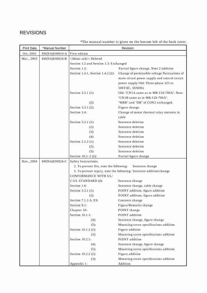
REVISIONS
*The manual number is given on the bottom left of the back cover.Print Data *Manual Number Revision
Oct, 2002 SH(NA)030024-A First editionMar., 2003 SH(NA)030024-B <About sale>: Deleted
Section 1.2 and Section 1.3: ExchangedSection 1.2: Partial figure change, Note 2 additionSection 1.4.1, Section 1.4.2 (2): Change of permissible voltage fluctuations of
main circuit power supply and control circuitpower supply Old: Three-phase 323 to506VAC, 50/60Hz
Section 3.2.1 (1): Old: "CN1A same as in MR-J2S-700A". New:"CN1B same as in MR-J2S-700A".
(2): "MBR" and "DB" of CON2 exchanged.Section 3.3.1 (2): Figure changeSection 3.4: Change of motor thermal relay contents in
tableSection 5.2.1 (1): Sentence deletion
(2): Sentence deletion(3): Sentence deletion(4): Sentence deletion
Section 5.2.2 (1): Sentence deletion(2): Sentence deletion(3): Sentence deletion
Section 10.2. 2 (2): Partial figure changeNov., 2004 SH(NA)030024-C Safety Instructions
2. To prevent fire, note the following: Sentence change3. To prevent injury, note the following: Sentence addition/change
CONFORMANCE WITH UL/C-UL STANDARD (4): Sentence changeSection 1.6: Sentence change, table changeSection 3.3.1 (1): POINT addition, figure addition
(2): POINT addition, figure additionSection 7.1.3 A. E9: Contents changeSection 9.1: Figure/Remarks changeChapter 10: POINT changeSection 10.1.1: POINT addition
(4): Sentence change, figure change(5): Mounting screw specifications addition
Section 10.1.2 (2): Figure addition(3): Mounting screw specifications addition
Section 10.2.1: POINT addition(4): Sentence change, figure change(5): Mounting screw specifications addition
Section 10.2.2 (2): Figure addition(3): Mounting screw specifications addition
Appendix 1: Addition

HEAD OFFICE:MITSUBISHI DENKI BLDG MARUNOUCHI TOKYO 100-8310
SH (NA) 030024-C (04011) MEE Printed in Japan Specifications subject to change without notice.This Instruction Manual uses recycled paper.
MODEL
MODELCODE
Related Documents


