General Product Catalogue

Welcome message from author
This document is posted to help you gain knowledge. Please leave a comment to let me know what you think about it! Share it to your friends and learn new things together.
Transcript

1
General ProductCatalogue

2
As INTERRA Family;We Are An Innovative, Young, Dynamic Brand That Loves Research And Development, Closely Follows The Technology...

3
Interra is a company that develops both software and hardware with its R&D teams experienced in the field of automation.
By aiming each product to primarily comply with high-quality standards, the company uses the highest quality components.
With this vision, Interra is a leader in the primary local and environmental markets, and is one of the important players in the global arena.

4
• Afghanistan• Albania• Algeria• Andorra• Angola• Argentina• Armenia• Australia• Austria• Azerbaijan• Bahrain• Bangladesh• Belarus• Belgium• Bolivia• Bosnia and H.• Brasil• Bulgaria• Burkina Faso• Cambodia• Cameruoon• Canada• Chile• China• Colombia• Costa Rİca• Croatia• Cuba• Cyprus Republic• Czech Republic• Denmark• Dominican R.
• Ecuador• Egypt• El Salvador• Estonia• Ethiopia• Finland• France• Georgia• Germany• Ghana• Greece• Guatemala• Guinea• Haiti• Honduras• Hungary• Iceland• India• Indonesia• Iran• Iraq• Ireland• Israel• Italy• Ivory Coast• Jamaica• Japan• Jordan• Kazakhistan• Kenya• Kirghizistan• Kosovo
• Kuwait• Latvia• Lebanon• Libya• Lithuania• Luxembourg• Macedonia• Malaysia• Malta• Mexico• Moldovia• Mongolia• Montenegro• Morocco• Mozambique• Myanmar• Nepal• Netherlands• New Zeland• Nigeria• North Korea• Norway• Oman• Pakistan• Palestine• Paraguay• Peru• Philippines• Poland• Portugal• Qatar• Romania
• Russia• Saudi Arabia• Senegal• Serbia• Singapore• Slovakia• Slovenia• South Africa• South Korea• South Sudan• Spain• Sudan• Sweden• Switzerland• Syria• T.R.N.C.• Taiwan• Tajikistan• Thailand• Tunusia• Turkey• Turkmenistan• U.A.E.• Ukraine• United Kingdom• Uruguay• USA• Uzbekistan• Venezuela• Vietnamase
interratechnology.com
5
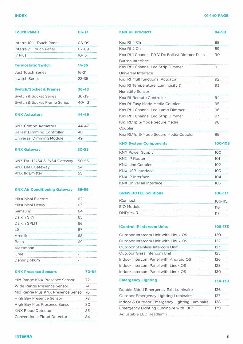
INDEX 01-140 PAGE
KNX Gateway 50-55
KNX Air Conditioning Gateway 56-69
KNX System Components
GRMS HOTEL Solutions 106-117
108-133
134-139
iControl IP Intercom Units
KNX Presence Sensors
Emergency Lighting
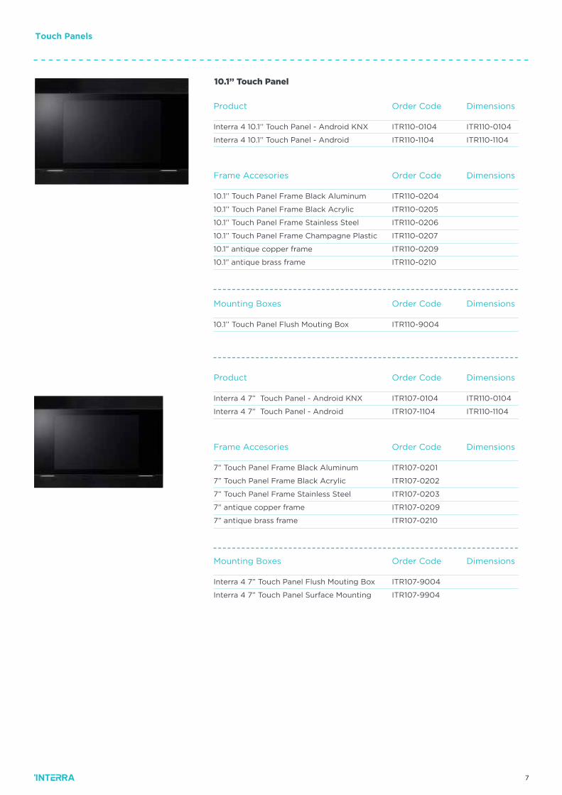
Interra 10.1’’ Touch Panel
Interra 7’’ Touch Panel
i7 Plus
06-09
07-09
10-13
KNX DALI 1x64 & 2x64 Gateway
KNX DMX Gateway
KNX IR Emitter
Mitsubishi Electric
Mitsubishi Heavy
Samsung
Daikin SKY
Daikin SPLIT
LG
Arçelik
Beko
Viessmann
Gree
Demir Döküm
KNX Power Supply
KNX IP Router
KNX Line Coupler
KNX USB Interface
KNX IP Interface
KNX Universal Interface
iConnect
EIO Module
DND/MUR
Outdoor Intercom Unit with Linux OS
Outdoor Intercom Unit with Linux OS
Outdoor Stainless Intercom Unit
Outdoor Glass Intercom Unit
Indoor Intercom Panel with Android OS
Indoor Intercom Panel with Linux OS
Indoor Intercom Panel with Linux OS
Mid Range KNX Presence Sensor
Wide Range Presence Sensor
Mid Range Plus KNX Presence Sensor
High Bay Presence Sensor
High Bay Plus Presence Sensor
KNX Flood Detector
Conventional Flood Detector
72
74
76
78
80
83
84
Double Sided Emergency Exit Luminaire
Outdoor Emergency Lighting Luminaire
Indoor & Outdoor Emergency Lighting Luminaire
Emergency Lighting Luminaire with 180°
Adjustable LED Headlamp
50-53
54
55
62
63
64
65
66
67
68
69
-
-
-
KNX RF Products 84-99
100-105
Touch Panels 06-13
Knx Rf 4 Ch
Knx Rf 2 Ch
Knx Rf 1 Channel 110 V Dc Ballast Dimmer Push
Button Interface
Knx Rf 1 Channel Led Strip Dimmer
Universal Interface
Knx Rf Multifunctional Actuator
Knx Rf Temperature, Luminosity &
Humidity Sensor
Knx Rf Remote Controller
Knx Rf Easy Mode Media Coupler
Knx Rf 1 Channel Led Lamp Dimmer
Knx Rf 1 Channel Led Strip Dimmer
Knx Rf/Tp S-Mode Secure Media
Coupler
Knx Rf/Tp S-Mode Secure Media Coupler
88
89
90
91
92
93
94
95
96
97
98
99
100
101
102
103
104
105
106-115
116
117
KNX Actuators 44-49
KNX Combo Actuators
Ballast Dimming Controller
Universal Dimming Module
44-47
48
49
Just Touch Series
Iswitch Series
16-21
22-35
Termostatic Switch 14-35
Switch & Socket Series
Switch & Socket Frame Series
36-39
40-43
Switch/Socket & Frames 36-43
70-84
120
122
123
125
126
128
130
136
137
138
139
6
7
Dimensions
Dimensions
Dimensions
Dimensions
Dimensions
Dimensions
Order Code
Order Code
Order Code
Order Code
Order Code
Order Code
10.1’’ Touch Panel
Product
Product
Frame Accesories
Frame Accesories
Mounting Boxes
Mounting Boxes
Interra 4 10.1’’ Touch Panel - Android KNX
Interra 4 10.1’’ Touch Panel - Android
Interra 4 7” Touch Panel - Android KNX
Interra 4 7” Touch Panel - Android
10.1’’ Touch Panel Frame Black Aluminum
10.1’’ Touch Panel Frame Black Acrylic
10.1’’ Touch Panel Frame Stainless Steel
10.1’’ Touch Panel Frame Champagne Plastic
10.1” antique copper frame
10.1” antique brass frame
7” Touch Panel Frame Black Aluminum
7” Touch Panel Frame Black Acrylic
7” Touch Panel Frame Stainless Steel
7” antique copper frame
7” antique brass frame
10.1’’ Touch Panel Flush Mouting Box
Interra 4 7” Touch Panel Flush Mouting Box
Interra 4 7” Touch Panel Surface Mounting
ITR110-0104
ITR110-1104
ITR107-0104
ITR107-1104
ITR110-0204
ITR110-0205
ITR110-0206
ITR110-0207
ITR110-0209
ITR110-0210
ITR107-0201
ITR107-0202
ITR107-0203
ITR107-0209
ITR107-0210
ITR110-9004
ITR107-9004
ITR107-9904
ITR110-0104
ITR110-1104
ITR110-0104
ITR110-1104
Touch Panels
8
DS190214128AEN © 2020 INTERRA
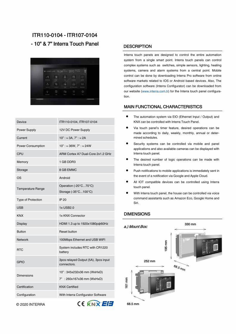
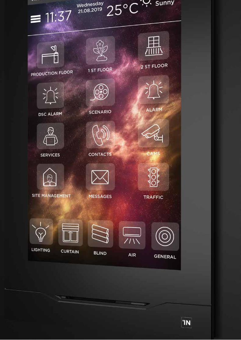
Interra touch panels are designed to control the entire automation system from a single smart point. Interra touch panels can control complex systems such as switches, simple sensors, lighting, heating systems, camera and alarm systems from a central point. Mobile control can be done by downloading Interra Pro software from online software markets related to IOS or Android based devices. Also, The configuration software (Interra Configurator) can be downloaded from our website (www.interra.com.tr) for the Interra touch panel configura-tion.
IITTRR111100--00110044 -- IITTRR110077--00110044 -- 1100”” && 77”” IInntteerrrraa TToouucchh PPaanneell
Device ITR110-0104, ITR107-0104
Power Supply 12V DC Power Supply
Current 10” : ≈ 3A, 7” : ≈ 2A
Power Consumption 10” : ≈ 36W, 7” : ≈ 24W
CPU ARM Cortex A7 Dual-Core 2x1.2 GHz
Memory 1 GB DDR3
Storage 8 GB EMMC
OS Android
Temperature Range Operation (-20°C...70°C)
Storage (-35°C...100°C)
Type of Protection IP 20
USB 1x USB2.0
KNX 1x KNX Connector
Display HDMI 1.3 up to 1920x1080p@60Hz
Button Reset button
Network 100Mbps Ethernet and USB WIFI
RTC System includes RTC with CR1220 battery
GPIO 3pcs relayed Output (5A), 3pcs input connectors.
Dimensions 10” : 345x232x36 mm (WxHxD)
7” : 260x167x36 mm (WxHxD)
Certification KNX Certified
Configuration With Interra Configurator Software
SSAAFFEETTYY IINNSSTTRRUUCCTTIIOONNSS
1
• The automation system via EIO (Ethernet Input / Output) and KNX can be controlled with Interra Touch Panel.
• Via touch panel’s timer feature, desired operations can be made according to daily, weekly, monthly, annual or deter-mined schedules.
• Security systems can be controlled via mobile and panel applications and also available cameras can be displayed with Interra touch panel.
• The desired number of logic operations can be made with Interra touch panel.
• Push notifications to mobile applications is immediately sent in the event of a notification via Google and Apple Cloud.
• All IOT compatible devices can be controlled using Interra touch panel.
• With Interra touch panel, the house can be controlled via voice command assistants such as Amazon Eco, Google Home and Siri.
MMAAIINN FFUUNNCCTTIIOONNAALL CCHHAARRAACCTTEERRIISSTTIICCSS
• The device may only be installed and put into operation by a qualified electrician or authorized personnel.
• For planning and construction of electric installations the appropriate specifications, guidelines and regulations in force of the respective country have to be complied.
• Do not connect the main voltage (230 VAC) or any other external voltages to any point of the KNX bus.
• Connecting an external voltage might put the KNX system into risk. Please, do not forget to consider this issue.
• Ensure that there is enough insulation between the 230 VAC voltage cables and KNX bus.
• Screwing torque value should be maximum 1.2nm during mounting process of mount case and touch panel.
• Do not use aerosol sprays, solvents or abrasives that might damage the device.
• Accessibility of the device for operation and visual inspection must be provided.
MMOOUUNNTTIINNGG
II//OO EETTHHEERRNNEETT VVOOLLTTAAGGEE KKNNXX HHDDMMII UUSSBB
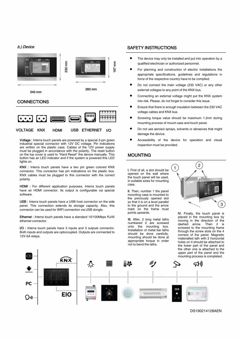
VVoollttaaggee :: Interra touch panels are powered by a special 3-pin green industrial special connector with 12V DC voltage. Pin indications are written on the plastic case. Cables of the 12V power supply must be plugged in accordance with the polarity. The reset button on the top cover is used to “Hard Reset” the device manually. This button has an LED indicator and if the system is powered this LED lights on. KKNNXX :: Interra touch panels have a two pin green colored KNX connector. This connector has pin indications on the plastic box. KNX cables must be plugged to this connector with the correct polarity.
HHDDMMII :: For different application purposes, Interra touch panels have an HDMI connector. Its output is configurable via special software.
UUSSBB :: Interra touch panels have a USB host connector on the side panel. This connection extends its storage capacity. Also, this connector can be used for WIFI connection via USB dongle.
EEtthheerrnneett :: Interra touch panels have a standard 10/100Mbps RJ45 ethernet connector.
II//OO :: Interra touch panels have 3 inputs and 3 outputs connector. Both inputs and outputs are optocoupled. Outputs are connected to 12V-5A relays.
DDEESSCCRRIIPPTTIIOONN
CCOONNNNEECCTTIIOONNSS
1
DDIIMMEENNSSIIOONNSS
333300 mmmm
119955
mmmm
116611
mmmm
225522 mmmm
aa..)) MMoouunntt BBooxx::
6688..55 mmmm
bb..)) DDeevviiccee
334455 mmmm 226600 mmmm
223322
mmmm
116677
mmmm
1 2
3
II.. First of all, a slot should be opened on the wall where the touch panel will be used, in suitable sizes for mounting case.
IIII.. Then, number 1 the panel mounting case is mounted to the previously opened slot so that it is on a level parallel to the ground and the arrow mark on the frame must points upwards.
IIIIII.. After, 2 long metal laths numbered 2 are screwed onto the mounting box. Installation of metal bar laths should be done carefully, mounting should be done at appropriate torque in order not to bend the laths.
IIVV.. Finally, the touch panel is placed in the mounting box by moving in the direction of the dashed arrow. Then it is screwed to the mounting frame through the screw slots on the 4 corners of the panel. Magnetic materialled lath with 2 horizontal holes on it should be attached to the lower part of the panel and the other one is attached to the upper part of the panel and the mounting process is completed.
9
DS190214128AEN © 2020 INTERRA
Interra touch panels are designed to control the entire automation system from a single smart point. Interra touch panels can control complex systems such as switches, simple sensors, lighting, heating systems, camera and alarm systems from a central point. Mobile control can be done by downloading Interra Pro software from online software markets related to IOS or Android based devices. Also, The configuration software (Interra Configurator) can be downloaded from our website (www.interra.com.tr) for the Interra touch panel configura-tion.
IITTRR111100--00110044 -- IITTRR110077--00110044 -- 1100”” && 77”” IInntteerrrraa TToouucchh PPaanneell
Device ITR110-0104, ITR107-0104
Power Supply 12V DC Power Supply
Current 10” : ≈ 3A, 7” : ≈ 2A
Power Consumption 10” : ≈ 36W, 7” : ≈ 24W
CPU ARM Cortex A7 Dual-Core 2x1.2 GHz
Memory 1 GB DDR3
Storage 8 GB EMMC
OS Android
Temperature Range Operation (-20°C...70°C)
Storage (-35°C...100°C)
Type of Protection IP 20
USB 1x USB2.0
KNX 1x KNX Connector
Display HDMI 1.3 up to 1920x1080p@60Hz
Button Reset button
Network 100Mbps Ethernet and USB WIFI
RTC System includes RTC with CR1220 battery
GPIO 3pcs relayed Output (5A), 3pcs input connectors.
Dimensions 10” : 345x232x36 mm (WxHxD)
7” : 260x167x36 mm (WxHxD)
Certification KNX Certified
Configuration With Interra Configurator Software
SSAAFFEETTYY IINNSSTTRRUUCCTTIIOONNSS
1
• The automation system via EIO (Ethernet Input / Output) and KNX can be controlled with Interra Touch Panel.
• Via touch panel’s timer feature, desired operations can be made according to daily, weekly, monthly, annual or deter-mined schedules.
• Security systems can be controlled via mobile and panel applications and also available cameras can be displayed with Interra touch panel.
• The desired number of logic operations can be made with Interra touch panel.
• Push notifications to mobile applications is immediately sent in the event of a notification via Google and Apple Cloud.
• All IOT compatible devices can be controlled using Interra touch panel.
• With Interra touch panel, the house can be controlled via voice command assistants such as Amazon Eco, Google Home and Siri.
MMAAIINN FFUUNNCCTTIIOONNAALL CCHHAARRAACCTTEERRIISSTTIICCSS
• The device may only be installed and put into operation by a qualified electrician or authorized personnel.
• For planning and construction of electric installations the appropriate specifications, guidelines and regulations in force of the respective country have to be complied.
• Do not connect the main voltage (230 VAC) or any other external voltages to any point of the KNX bus.
• Connecting an external voltage might put the KNX system into risk. Please, do not forget to consider this issue.
• Ensure that there is enough insulation between the 230 VAC voltage cables and KNX bus.
• Screwing torque value should be maximum 1.2nm during mounting process of mount case and touch panel.
• Do not use aerosol sprays, solvents or abrasives that might damage the device.
• Accessibility of the device for operation and visual inspection must be provided.
MMOOUUNNTTIINNGG
II//OO EETTHHEERRNNEETT VVOOLLTTAAGGEE KKNNXX HHDDMMII UUSSBB
VVoollttaaggee :: Interra touch panels are powered by a special 3-pin green industrial special connector with 12V DC voltage. Pin indications are written on the plastic case. Cables of the 12V power supply must be plugged in accordance with the polarity. The reset button on the top cover is used to “Hard Reset” the device manually. This button has an LED indicator and if the system is powered this LED lights on. KKNNXX :: Interra touch panels have a two pin green colored KNX connector. This connector has pin indications on the plastic box. KNX cables must be plugged to this connector with the correct polarity.
HHDDMMII :: For different application purposes, Interra touch panels have an HDMI connector. Its output is configurable via special software.
UUSSBB :: Interra touch panels have a USB host connector on the side panel. This connection extends its storage capacity. Also, this connector can be used for WIFI connection via USB dongle.
EEtthheerrnneett :: Interra touch panels have a standard 10/100Mbps RJ45 ethernet connector.
II//OO :: Interra touch panels have 3 inputs and 3 outputs connector. Both inputs and outputs are optocoupled. Outputs are connected to 12V-5A relays.
DDEESSCCRRIIPPTTIIOONN
CCOONNNNEECCTTIIOONNSS
1
DDIIMMEENNSSIIOONNSS
333300 mmmm
119955
mmmm
116611
mmmm
225522 mmmm
aa..)) MMoouunntt BBooxx::
6688..55 mmmm
bb..)) DDeevviiccee
334455 mmmm 226600 mmmm
223322
mmmm
116677
mmmm
1 2
3
II.. First of all, a slot should be opened on the wall where the touch panel will be used, in suitable sizes for mounting case.
IIII.. Then, number 1 the panel mounting case is mounted to the previously opened slot so that it is on a level parallel to the ground and the arrow mark on the frame must points upwards.
IIIIII.. After, 2 long metal laths numbered 2 are screwed onto the mounting box. Installation of metal bar laths should be done carefully, mounting should be done at appropriate torque in order not to bend the laths.
IIVV.. Finally, the touch panel is placed in the mounting box by moving in the direction of the dashed arrow. Then it is screwed to the mounting frame through the screw slots on the 4 corners of the panel. Magnetic materialled lath with 2 horizontal holes on it should be attached to the lower part of the panel and the other one is attached to the upper part of the panel and the mounting process is completed.
10
11
Touch Panels
Dimensions
Dimensions
Dimensions
Order Code
Order Code
Order Code
i7+ Plus
Product
Frame Accesories
Mounting Boxes
Interra i7+ Touch Panel
Interra i7+ Touch Panel frame
10.1’’ Touch Panel Flush Mouting Box
ITR165-0002
ITR165-1002
ITR110-9004
120x180mm

12
DS210107188AEN © 2021 INTERRA
Interra i7+ touch panel is designed to control the entire automation system from a single smart point. Interra I7+ can control complex systems such as switches, simple sensors, lighting, camera systems and alarm systems from a central point. Moreover, i7+ can also control the air conditioning systems with 2-point mode by thermostat function-ality. Mobile control can be done by downloading Interra Pro software from online software markets related to IOS or Android based devices. Also, The configuration software (Interra Configurator) can be down-loaded from our website (www.interra.com.tr) for the i7+ touch panel configuration.
IITTRR116655--00000022 -- ii77++ TToouucchh PPaanneell
Device ITR165-0002
Power Supply 12V-2A DC Power Supply
CPU ARM Cortex A7 Dual-Core 2x1.2 GHz
Memory 1 GB DDR3
Storage 8 GB EMMC
OS Android
USB 1x USB2.0
KNX 1x KNX Connector
Sensors 1xTemperature Sensor
Display 7” LCD, HDMI 1.3 up to1920x1080p@60Hz
Network 100Mbps Ethernet and USB WIFI
RTC System includes RTC with CR1220 battery
GPIO 3pcs relayed Output (5A), 3pcs input connect-ors.
Temperature Range Operation (0°C...45°C)
Storage (-15°C...70°C)
Dimensions I7+ Panel : 170x65x90 mm (WxHxD)
Mounting Box : 116x201x65 mmm (WxHxD)
Certification KNX Certified
Configuration With Interra Configurator Software
DDIIMMEENNSSIIOONNSS
1/1
MMAAIINN FFUUNNCCTTIIOONNAALL CCHHAARRAACCTTEERRIISSTTIICCSS
DDEESSCCRRIIPPTTIIOONN CCOONNNNEECCTTIIOONNSS
MMOOUUNNTTIINNGG
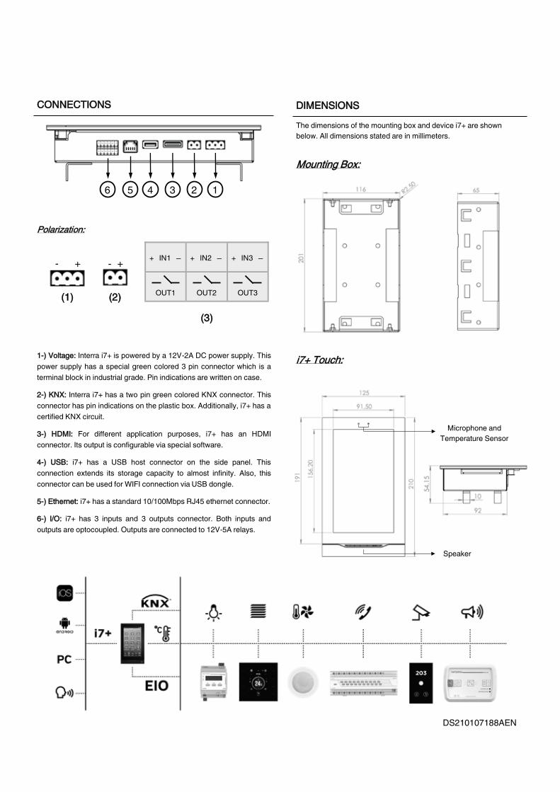
11--)) VVoollttaaggee:: Interra i7+ is powered by a 12V-2A DC power supply. This power supply has a special green colored 3 pin connector which is a terminal block in industrial grade. Pin indications are written on case.
22--)) KKNNXX:: Interra i7+ has a two pin green colored KNX connector. This connector has pin indications on the plastic box. Additionally, i7+ has a certified KNX circuit.
33--)) HHDDMMII:: For different application purposes, i7+ has an HDMI connector. Its output is configurable via special software.
44--)) UUSSBB:: i7+ has a USB host connector on the side panel. This connection extends its storage capacity to almost infinity. Also, this connector can be used for WIFI connection via USB dongle.
55--)) EEtthheerrnneett:: i7+ has a standard 10/100Mbps RJ45 ethernet connector.
66--)) II//OO:: i7+ has 3 inputs and 3 outputs connector. Both inputs and outputs are optocoupled. Outputs are connected to 12V-5A relays.
• The automation system via EIO (Ethernet Input / Output) and KNX can be controlled with i7+ touch panel.
• Via i7+ touch panel’s timer feature, desired operations can be made according to daily, weekly, monthly, annual or determined sched-ules.
• Security systems can be controlled via mobile and panel applica-tions and also available cameras can be displayed with i7+ .
• Air conditioning systems can be controlled by thermostat function. 2-point on/off control can be made according to configured hysteresis with internal sensor or external source.
• The desired number of logic operations can be made with i7+ .
• Push notifications to mobile applications is immediately sent in the event of a notification via Google and Apple Cloud.
• All IOT compatible devices can be controlled using i7+ .
• With i7+, the house can be controlled via voice command assistants such as Amazon Eco, Google Home and Siri.
ii77++ TToouucchh::
MMoouunnttiinngg BBooxx::
The dimensions of the mounting box and device i7+ are shown below. All dimensions stated are in millimeters.
First, the mounting box must be attached to a suitable place on the wall. The long side of the mounting box should be placed at a right angle to the ground.
Then i7+ is attached to the mounting box as shown in the left figure and the mounting process is completed.
Speaker
Microphone and Temperature Sensor
+ - + - + IN1 ─ + IN2 ─ + IN3 ─
OUT1 OUT2 OUT3
6 5 4 3 2 1
PPoollaarriizzaattiioonn::
((11)) ((22))
((33))
13
DS210107188AEN © 2021 INTERRA
Interra i7+ touch panel is designed to control the entire automation system from a single smart point. Interra I7+ can control complex systems such as switches, simple sensors, lighting, camera systems and alarm systems from a central point. Moreover, i7+ can also control the air conditioning systems with 2-point mode by thermostat function-ality. Mobile control can be done by downloading Interra Pro software from online software markets related to IOS or Android based devices. Also, The configuration software (Interra Configurator) can be down-loaded from our website (www.interra.com.tr) for the i7+ touch panel configuration.
IITTRR116655--00000022 -- ii77++ TToouucchh PPaanneell
Device ITR165-0002
Power Supply 12V-2A DC Power Supply
CPU ARM Cortex A7 Dual-Core 2x1.2 GHz
Memory 1 GB DDR3
Storage 8 GB EMMC
OS Android
USB 1x USB2.0
KNX 1x KNX Connector
Sensors 1xTemperature Sensor
Display 7” LCD, HDMI 1.3 up to1920x1080p@60Hz
Network 100Mbps Ethernet and USB WIFI
RTC System includes RTC with CR1220 battery
GPIO 3pcs relayed Output (5A), 3pcs input connect-ors.
Temperature Range Operation (0°C...45°C)
Storage (-15°C...70°C)
Dimensions I7+ Panel : 170x65x90 mm (WxHxD)
Mounting Box : 116x201x65 mmm (WxHxD)
Certification KNX Certified
Configuration With Interra Configurator Software
DDIIMMEENNSSIIOONNSS
1/1
MMAAIINN FFUUNNCCTTIIOONNAALL CCHHAARRAACCTTEERRIISSTTIICCSS
DDEESSCCRRIIPPTTIIOONN CCOONNNNEECCTTIIOONNSS
MMOOUUNNTTIINNGG
11--)) VVoollttaaggee:: Interra i7+ is powered by a 12V-2A DC power supply. This power supply has a special green colored 3 pin connector which is a terminal block in industrial grade. Pin indications are written on case.
22--)) KKNNXX:: Interra i7+ has a two pin green colored KNX connector. This connector has pin indications on the plastic box. Additionally, i7+ has a certified KNX circuit.
33--)) HHDDMMII:: For different application purposes, i7+ has an HDMI connector. Its output is configurable via special software.
44--)) UUSSBB:: i7+ has a USB host connector on the side panel. This connection extends its storage capacity to almost infinity. Also, this connector can be used for WIFI connection via USB dongle.
55--)) EEtthheerrnneett:: i7+ has a standard 10/100Mbps RJ45 ethernet connector.
66--)) II//OO:: i7+ has 3 inputs and 3 outputs connector. Both inputs and outputs are optocoupled. Outputs are connected to 12V-5A relays.
• The automation system via EIO (Ethernet Input / Output) and KNX can be controlled with i7+ touch panel.
• Via i7+ touch panel’s timer feature, desired operations can be made according to daily, weekly, monthly, annual or determined sched-ules.
• Security systems can be controlled via mobile and panel applica-tions and also available cameras can be displayed with i7+ .
• Air conditioning systems can be controlled by thermostat function. 2-point on/off control can be made according to configured hysteresis with internal sensor or external source.
• The desired number of logic operations can be made with i7+ .
• Push notifications to mobile applications is immediately sent in the event of a notification via Google and Apple Cloud.
• All IOT compatible devices can be controlled using i7+ .
• With i7+, the house can be controlled via voice command assistants such as Amazon Eco, Google Home and Siri.
ii77++ TToouucchh::
MMoouunnttiinngg BBooxx::
The dimensions of the mounting box and device i7+ are shown below. All dimensions stated are in millimeters.
First, the mounting box must be attached to a suitable place on the wall. The long side of the mounting box should be placed at a right angle to the ground.
Then i7+ is attached to the mounting box as shown in the left figure and the mounting process is completed.
Speaker
Microphone and Temperature Sensor
+ - + - + IN1 ─ + IN2 ─ + IN3 ─
OUT1 OUT2 OUT3
6 5 4 3 2 1
PPoollaarriizzaattiioonn::
((11)) ((22))
((33))
14
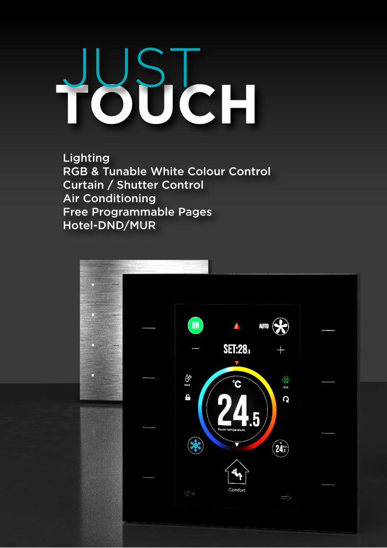
LightingRGB & Tunable White Colour ControlCurtain / Shutter Control Air ConditioningFree Programmable PagesHotel-DND/MUR
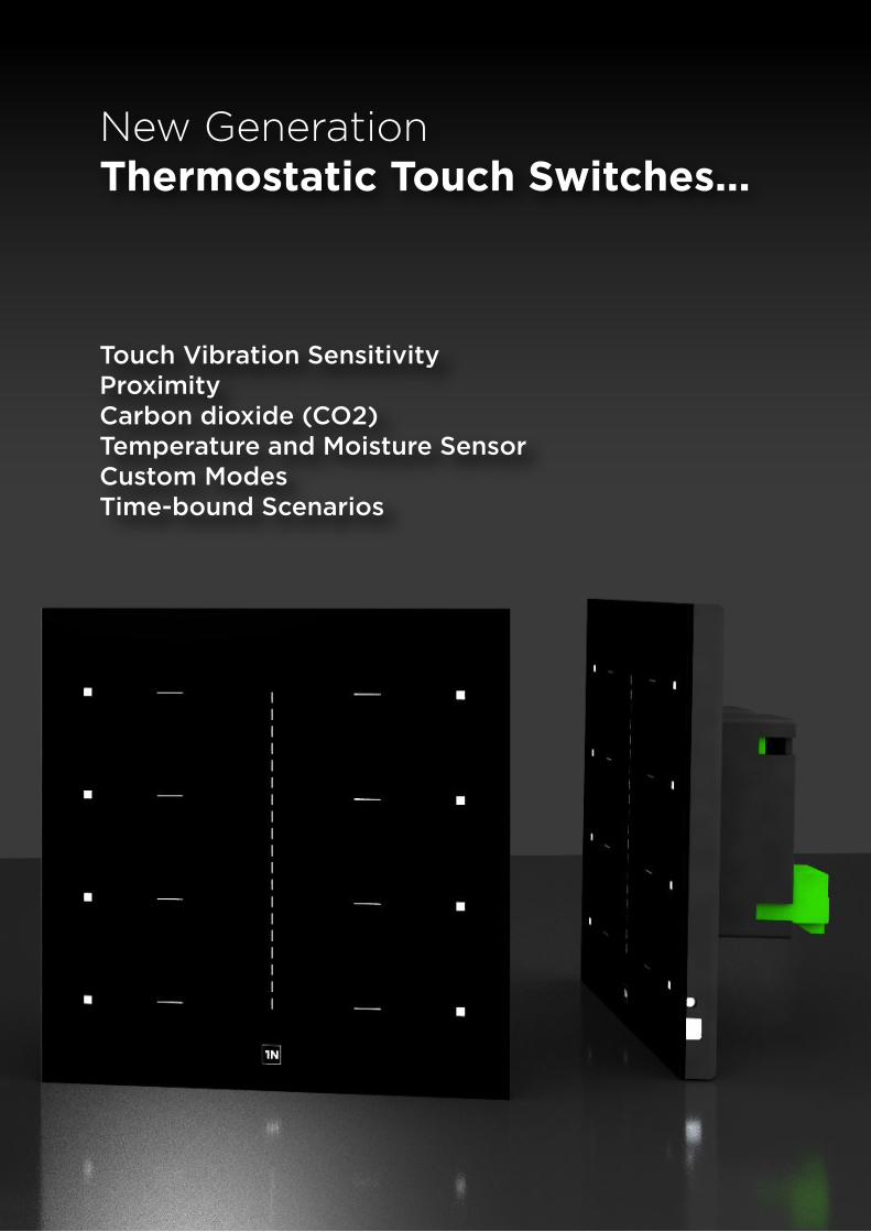
Touch Vibration SensitivityProximityCarbon dioxide (CO2)Temperature and Moisture SensorCustom ModesTime-bound Scenarios
New GenerationThermostatic Touch Switches...
15
LightingRGB & Tunable White Colour ControlCurtain / Shutter Control Air ConditioningFree Programmable PagesHotel-DND/MUR
Touch Vibration SensitivityProximityCarbon dioxide (CO2)Temperature and Moisture SensorCustom ModesTime-bound Scenarios
New GenerationThermostatic Touch Switches...
16
Dimensions
Dimensions
Order Code
Order Code
Product
Product
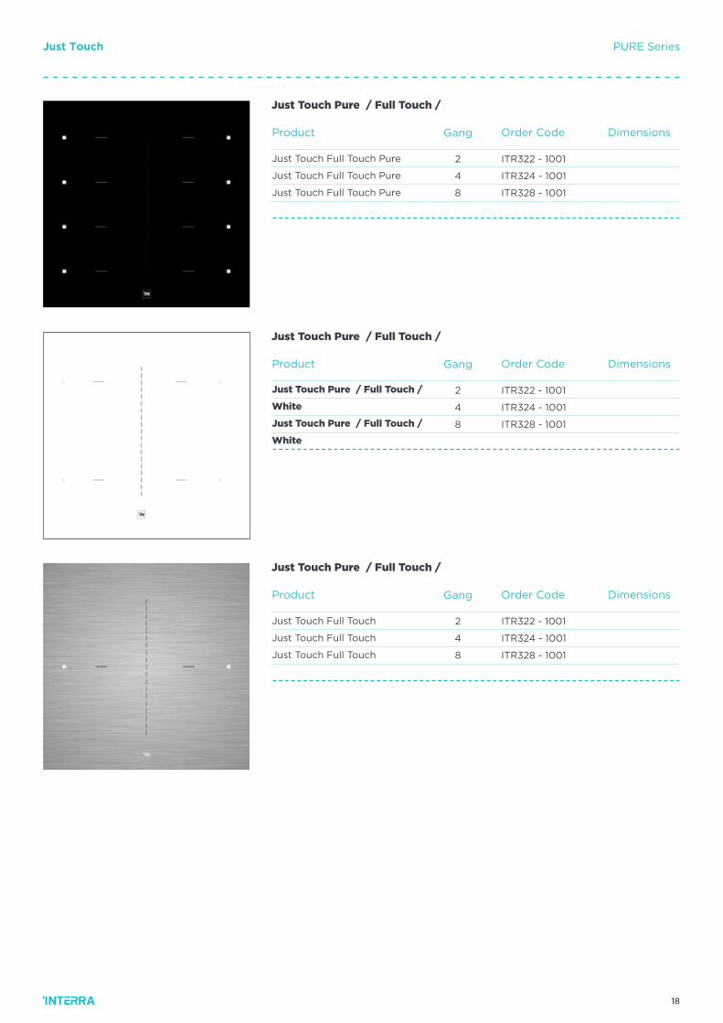
ITR322 - 1001
ITR324 - 1001
ITR328 - 1001
ITR322 - 1001
ITR324 - 1001
ITR328 - 1001
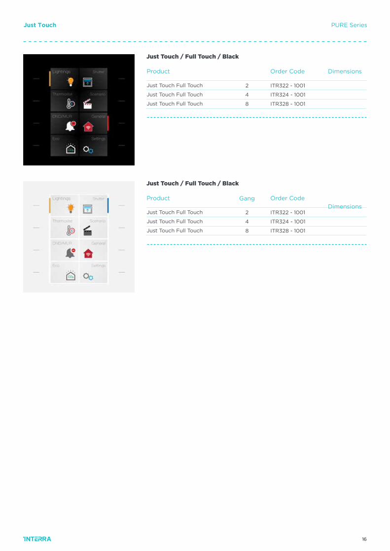
Just Touch Full Touch
Just Touch Full Touch
Just Touch Full Touch
Just Touch Full Touch
Just Touch Full Touch
Just Touch Full Touch
Just Touch / Full Touch / Black
Just Touch / Full Touch / Black
Gang
2
4
8
2
4
8
Just Touch PURE Series
17
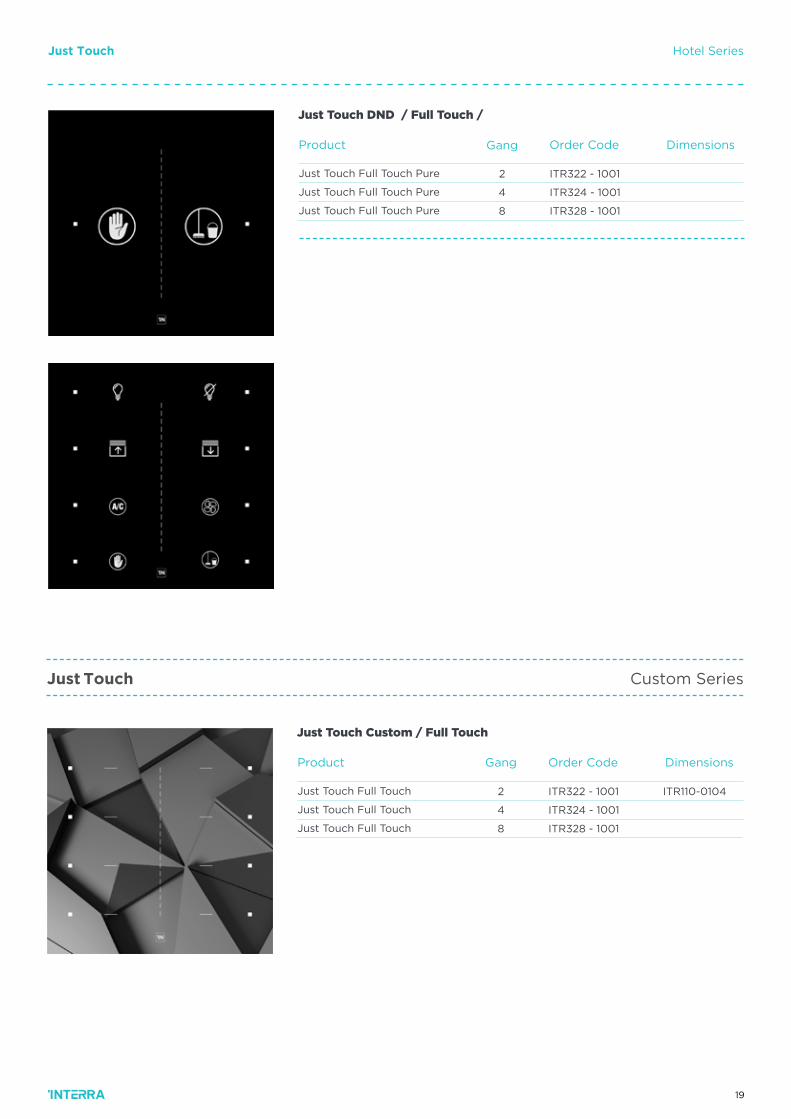
Dimensions
Dimensions
Dimensions
Order Code
Order Code
Order Code
Product
Product
Product
ITR322 - 1001
ITR324 - 1001
ITR328 - 1001
ITR322 - 1001
ITR324 - 1001
ITR328 - 1001
ITR322 - 1001
ITR324 - 1001
ITR328 - 1001
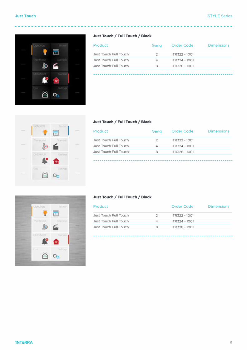
Just Touch Full Touch
Just Touch Full Touch
Just Touch Full Touch
Just Touch Full Touch
Just Touch Full Touch
Just Touch Full Touch
Just Touch Full Touch
Just Touch Full Touch
Just Touch Full Touch
Just Touch / Full Touch / Black
Just Touch / Full Touch / Black
Just Touch / Full Touch / Black
Gang
Gang
2
4
8
2
4
8
2
4
8
Just Touch STYLE Series
18
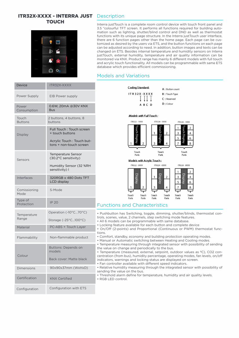
Dimensions
Dimensions
Dimensions
Order Code
Order Code
Order Code
Product
Product
Product
ITR322 - 1001
ITR324 - 1001
ITR328 - 1001
ITR322 - 1001
ITR324 - 1001
ITR328 - 1001
ITR322 - 1001
ITR324 - 1001
ITR328 - 1001
Just Touch Full Touch Pure
Just Touch Full Touch Pure
Just Touch Full Touch Pure
Just Touch Pure / Full Touch /
White
Just Touch Pure / Full Touch /
White
Just Touch Full Touch
Just Touch Full Touch
Just Touch Full Touch
Just Touch Pure / Full Touch /
Just Touch Pure / Full Touch /
Just Touch Pure / Full Touch /
Gang
Gang
Gang
2
4
8
2
4
8
2
4
8
Just Touch PURE Series
19
DimensionsOrder CodeProduct
ITR322 - 1001
ITR324 - 1001
ITR328 - 1001
ITR110-0104Just Touch Full Touch
Just Touch Full Touch
Just Touch Full Touch
Just Touch Custom / Full Touch
Gang
2
4
8
Just Touch
Just Touch
Custom Series
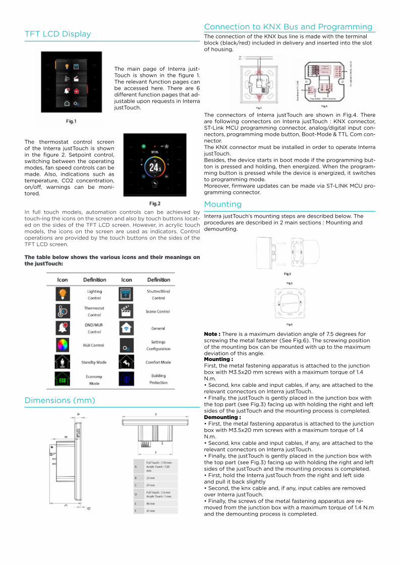
Hotel Series
DimensionsOrder CodeProduct
ITR322 - 1001
ITR324 - 1001
ITR328 - 1001
Just Touch Full Touch Pure
Just Touch Full Touch Pure
Just Touch Full Touch Pure
Just Touch DND / Full Touch /
Gang
2
4
8
20
Description
Functions and Characteristics
Models and Variations
Interra justTouch is a complete room control device with touch front panel and 3.5 “colourful TFT screen. It performs all functions required for building auto-mation such as lighting, shutter/blind control and DND as well as thermostat functions with its unique page structure. In the Interra justTouch user interface, there are 6 function pages other than the home page. Each page can be cus-tomized as desired by the users via ETS, and the button functions on each page can be adjusted according to need. In addition, button images and texts can be changed on ETS. Besides internal temperature and humidity sensors on Interra justTouch, external humidity, temperature and air quality information can be monitored via KNX. Product range has mainly 6 different models with full touch and acrylic touch functionality. All models can be programmable with same ETS database which provides efficient commissioning.
• Pushbutton has Switching, toggle, dimming, shutter/blinds, thermostat con-trols, scenes, value, 2 channels, step switching mode features.• All 6 models can be programmable with same database.• Locking feature available for each button and complete device• On/Off (2-points) and Proportional (Continuous or PWM) thermostat func-tions.• Comfort, standby, economy and building protection operating modes.• Manual or Automatic switching between Heating and Cooling modes.• Temperature measuring through integrated sensor with possibility of sending the value on change and periodically to the bus.• Temperature (measured, external, setpoint, outdoor values as ºC), CO2 con-centration (from bus), humidity percentage, operating modes, fan levels, on/off indicators, warnings and locking status are displayed on screen.• Fan controller available with different speed indicators.• Relative humidity measuring through the integrated sensor with possibility of sending the value on the bus.• Threshold alarm define for temperature, humidity and air quality levels.• RGB LED control.
Power Supply
PowerConsumption
TouchButtons
Display
Certification
Sensors
Interfaces
Type of Protection
Colour
Flammability
ITR32X-XXXX
EIB Power supply
0.6W, 20mA @30V KNX Bus
2 buttons, 4 buttons, 8 buttons
S-Mode
IP 20
KNX Certified
Buttons: Depends on models
Back cover: Matte black
Non-flammable product
ITR32X-XXXX - INTERRA JUST TOUCH
ComissioningMode
Full Touch : Touch screen + touch buttons
Acrylic Touch : Touch but-tons + non-touch screen
Temperature Sensor (±0.2°C sensitivity)
Humidity Sensor (±2 %RH sensitivity) l
Configuration
TemperatureRange
Configuration with ETS
Operation (-10°C...70°C)
Storage (-25°C...100°C)
320RGB x 480 Dots TFT LCD display
Device
Dimensions
Material
90x90x37mm (WxHxD)
PC-ABS + Touch Layer
21
TFT LCD DisplayConnection to KNX Bus and Programming
Mounting
Dimensions (mm)
The main page of Interra just-Touch is shown in the figure 1. The relevant function pages can be accessed here. There are 6 different function pages that ad-justable upon requests in Interra justTouch.
The thermostat control screen of the Interra justTouch is shown in the figure 2. Setpoint control, switching between the operating modes, fan speed controls can be made. Also, indications such as temperature, CO2 concentration, on/off, warnings can be moni-tored.
In full touch models, automation controls can be achieved by touch-ing the icons on the screen and also by touch buttons locat-ed on the sides of the TFT LCD screen. However, in acrylic touch models, the icons on the screen are used as indicators. Control operations are provided by the touch buttons on the sides of the TFT LCD screen.
The table below shows the various icons and their meanings on the justTouch:
The connection of the KNX bus line is made with the terminal block (black/red) included in delivery and inserted into the slot of housing.
Interra justTouch’s mounting steps are described below. The procedures are described in 2 main sections : Mounting and demounting.
Note : There is a maximum deviation angle of 7.5 degrees for screwing the metal fastener (See Fig.6). The screwing position of the mounting box can be mounted with up to the maximum deviation of this angle.
The connectors of Interra justTouch are shown in Fig.4. There are following connectors on Interra justTouch : KNX connector, ST-Link MCU programming connector, analog/digital input con-nectors, programming mode button, Boot-Mode & TTL Com con-nector.The KNX connector must be installed in order to operate Interra justTouch.Besides, the device starts in boot mode if the programming but-ton is pressed and holding, then energized. When the program-ming button is pressed while the device is energized, it switches to programming mode.Moreover, firmware updates can be made via ST-LINK MCU pro-gramming connector.
Mounting :First, the metal fastening apparatus is attached to the junction box with M3.5x20 mm screws with a maximum torque of 1.4 N.m.• Second, knx cable and input cables, if any, are attached to the relevant connectors on Interra justTouch.• Finally, the justTouch is gently placed in the junction box with the top part (see Fig.3) facing up with holding the right and left sides of the justTouch and the mounting process is completed.Demounting :• First, the metal fastening apparatus is attached to the junction box with M3.5x20 mm screws with a maximum torque of 1.4 N.m.• Second, knx cable and input cables, if any, are attached to the relevant connectors on Interra justTouch.• Finally, the justTouch is gently placed in the junction box with the top part (see Fig.3) facing up with holding the right and left sides of the justTouch and the mounting process is completed.• First, hold the Interra justTouch from the right and left side and pull it back slightly• Second, the knx cable and, if any, input cables are removed over Interra justTouch.• Finally, the screws of the metal fastening apparatus are re-moved from the junction box with a maximum torque of 1.4 N.m and the demounting process is completed.

22
Interra IswitchElegant & Smart & Universal
interra.com.tr
23
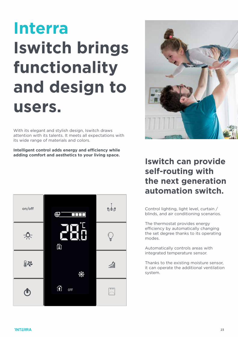
With its elegant and stylish design, Iswitch draws attention with its talents. It meets all expectations with its wide range of materials and colors.
Intelligent control adds energy and efficiency while adding comfort and aesthetics to your living space.
Interra Iswitch brings functionality and design to users.
Iswitch can provide self-routing with the next generation automation switch.
Control lighting, light level, curtain / blinds, and air conditioning scenarios.
The thermostat provides energy efficiency by automatically changing the set degree thanks to its operating modes.
Automatically controls areas with integrated temperature sensor.
Thanks to the existing moisture sensor, it can operate the additional ventilation system.
24
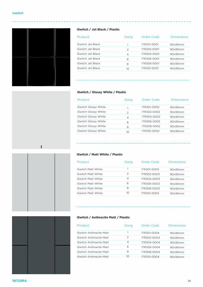
DimensionsOrder CodeProduct
ITR301-0001
ITR302-0001
ITR304-0001
ITR306-0001
ITR308-0001
ITR310-0001
90x90mm
90x90mm
90x90mm
90x90mm
90x90mm
90x90mm
iSwitch Jet Black
iSwitch Jet Black
iSwitch Jet Black
iSwitch Jet Black
iSwitch Jet Black
iSwitch Jet Black
iSwitch / Jet Black / Plastic
90x90mm
90x90mm
90x90mm
90x90mm
90x90mm
90x90mm
DimensionsOrder CodeProduct Gang
ITR301-0002
ITR302-0002
ITR304-0002
ITR306-0002
ITR308-0002
ITR310-0002
iSwitch Glossy White
iSwitch Glossy White
iSwitch Glossy White
iSwitch Glossy White
iSwitch Glossy White
iSwitch Glossy White
1
2
4
6
8
10
iSwitch / Glossy White / Plastic
Gang
1
2
4
6
8
10
90x90mm
90x90mm
90x90mm
90x90mm
90x90mm
90x90mm
DimensionsOrder CodeProduct
ITR301-0003
ITR302-0003
ITR304-0003
ITR306-0003
ITR308-0003
ITR310-0003
iSwitch Matt White
iSwitch Matt White
iSwitch Matt White
iSwitch Matt White
iSwitch Matt White
iSwitch Matt White
iSwitch / Matt White / Plastic
Gang
1
2
4
6
8
10
90x90mm
90x90mm
90x90mm
90x90mm
90x90mm
90x90mm
DimensionsOrder CodeProduct
ITR301-0004
ITR302-0004
ITR304-0004
ITR306-0004
ITR308-0004
ITR310-0004
iSwitch Anthracite Matt
iSwitch Anthracite Matt
iSwitch Anthracite Matt
iSwitch Anthracite Matt
iSwitch Anthracite Matt
iSwitch Anthracite Matt
iSwitch / Anthracite Matt / Plastic
Gang
1
2
4
6
8
10
Iswitch
25
DimensionsOrder CodeProduct
ITR301-0005
ITR302-0005
ITR304-0005
ITR306-0005
ITR308-0005
ITR310-0005
ITR110-0104
ITR110-1104
iSwitch Metallic Gray
iSwitch Metallic Gray
iSwitch Metallic Gray
iSwitch Metallic Gray
iSwitch Metallic Gray
iSwitch Metallic Gray
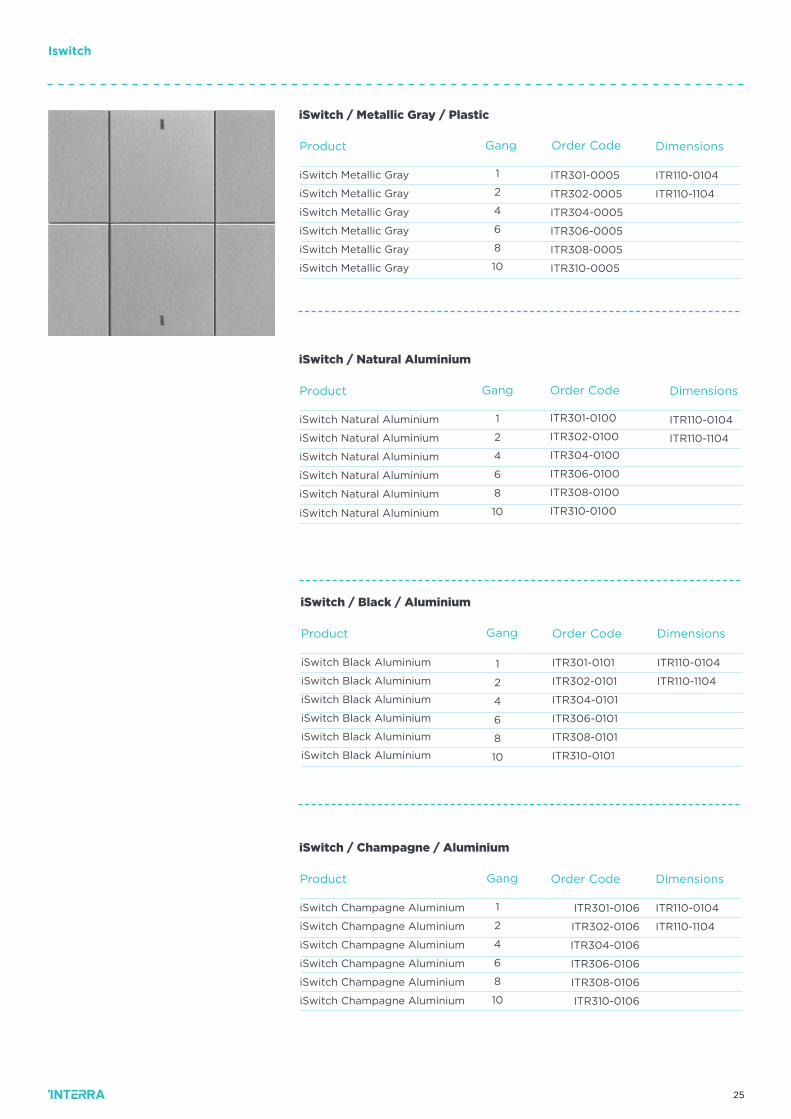
iSwitch / Metallic Gray / Plastic
Gang
1
2
4
6
8
10
DimensionsOrder CodeProduct
ITR301-0100
ITR302-0100
ITR304-0100
ITR306-0100
ITR308-0100
ITR310-0100
ITR110-0104
ITR110-1104
iSwitch Natural Aluminium
iSwitch Natural Aluminium
iSwitch Natural Aluminium
iSwitch Natural Aluminium
iSwitch Natural Aluminium
iSwitch Natural Aluminium
iSwitch / Natural Aluminium
Gang
1
2
4
6
8
10
DimensionsOrder CodeProduct
ITR301-0101
ITR302-0101
ITR304-0101
ITR306-0101
ITR308-0101
ITR310-0101
ITR110-0104
ITR110-1104
iSwitch Black Aluminium
iSwitch Black Aluminium
iSwitch Black Aluminium
iSwitch Black Aluminium
iSwitch Black Aluminium
iSwitch Black Aluminium
iSwitch / Black / Aluminium
Gang
1
2
4
6
8
10
DimensionsOrder CodeProduct
ITR301-0106
ITR302-0106
ITR304-0106
ITR306-0106
ITR308-0106
ITR310-0106
ITR110-0104
ITR110-1104
iSwitch Champagne Aluminium
iSwitch Champagne Aluminium
iSwitch Champagne Aluminium
iSwitch Champagne Aluminium
iSwitch Champagne Aluminium
iSwitch Champagne Aluminium
iSwitch / Champagne / Aluminium
Gang
1
2
4
6
8
10
Iswitch
26
Order CodeProduct
ITR301-0200
ITR302-0200
ITR304-0200
ITR306-0200
ITR308-0200
ITR310-0200
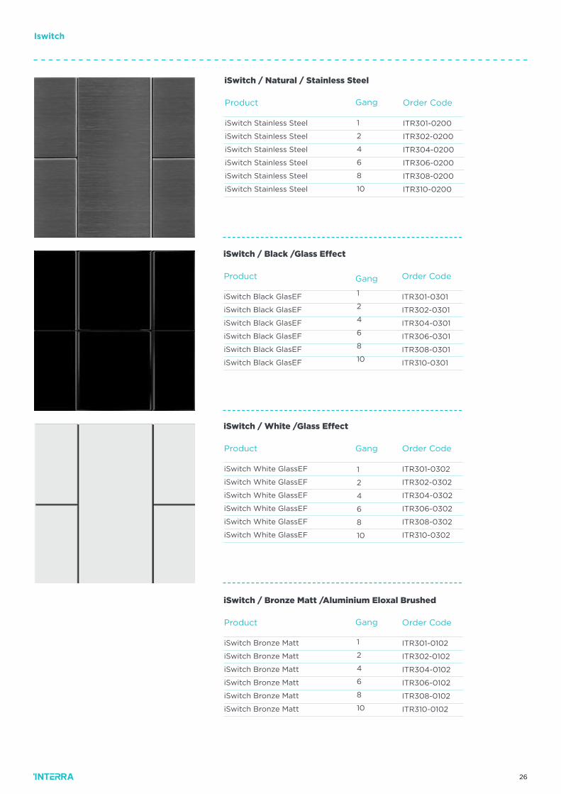
iSwitch Stainless Steel
iSwitch Stainless Steel
iSwitch Stainless Steel
iSwitch Stainless Steel
iSwitch Stainless Steel
iSwitch Stainless Steel
iSwitch / Natural / Stainless Steel
Gang
1
2
4
6
8
10
Order CodeProduct
ITR301-0301
ITR302-0301
ITR304-0301
ITR306-0301
ITR308-0301
ITR310-0301
iSwitch Black GlasEF
iSwitch Black GlasEF
iSwitch Black GlasEF
iSwitch Black GlasEF
iSwitch Black GlasEF
iSwitch Black GlasEF
iSwitch / Black /Glass Effect
Gang
1
2
4
6
8
10
Order CodeProduct
ITR301-0302
ITR302-0302
ITR304-0302
ITR306-0302
ITR308-0302
ITR310-0302
iSwitch White GlassEF
iSwitch White GlassEF
iSwitch White GlassEF
iSwitch White GlassEF
iSwitch White GlassEF
iSwitch White GlassEF
iSwitch / White /Glass Effect
Gang
1
2
4
6
8
10
Order CodeProduct
ITR301-0102
ITR302-0102
ITR304-0102
ITR306-0102
ITR308-0102
ITR310-0102
iSwitch Bronze Matt
iSwitch Bronze Matt
iSwitch Bronze Matt
iSwitch Bronze Matt
iSwitch Bronze Matt
iSwitch Bronze Matt
iSwitch / Bronze Matt /Aluminium Eloxal Brushed
Gang
1
2
4
6
8
10
Iswitch
27
Order CodeProduct
ITR301-0207
ITR302-0207
ITR304-0207
ITR306-0207
ITR308-0207
ITR310-0207
iSwitch Antique Copper
iSwitch Antique Copper
iSwitch Antique Copper
iSwitch Antique Copper
iSwitch Antique Copper
iSwitch Antique Copper
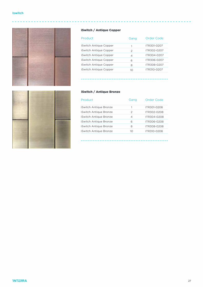
iSwitch / Antique Copper
Gang
1
2
4
6
8
10
Order CodeProduct
ITR301-0208
ITR302-0208
ITR304-0208
ITR306-0208
ITR308-0208
ITR310-0208
iSwitch Antique Bronze
iSwitch Antique Bronze
iSwitch Antique Bronze
iSwitch Antique Bronze
iSwitch Antique Bronze
iSwitch Antique Bronze
iSwitch / Antique Bronze
1
2
4
6
8
10
Gang
Iswitch
28
Order CodeProduct
ITR302-1003
ITR302-1003
ITR302-1003
iSwitch Matt White
iSwitch Matt White
iSwitch Matt White
2
4
8
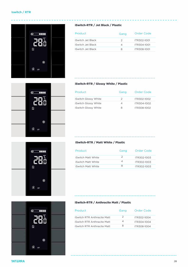
iSwitch-RTR / Matt White / Plastic
Gang
Iswitch / RTR
Order CodeProduct
ITR302-1001
ITR304-1001
ITR308-1001
iSwitch Jet Black
iSwitch Jet Black
iSwitch Jet Black
2
4
8
iSwitch-RTR / Jet Black / Plastic
Gang
Order CodeProduct
ITR302-1002
ITR304-1002
ITR308-1002
iSwitch Glossy White
iSwitch Glossy White
iSwitch Glossy White
2
4
8
iSwitch-RTR / Glossy White / Plastic
Gang
Order CodeProduct
ITR302-1004
ITR304-1004
ITR308-1004
iSwitch RTR Anthracite Matt
iSwitch RTR Anthracite Matt
iSwitch RTR Anthracite Matt
2
4
8
iSwitch-RTR / Anthracite Matt / Plastic
Gang
29
Iswitch / RTR
Order CodeProduct
ITR302-1005
ITR304-1005
ITR308-1005
iSwitch RTR Metallic Gray
iSwitch RTR Metallic Gray
iSwitch RTR Metallic Gray
2
4
8
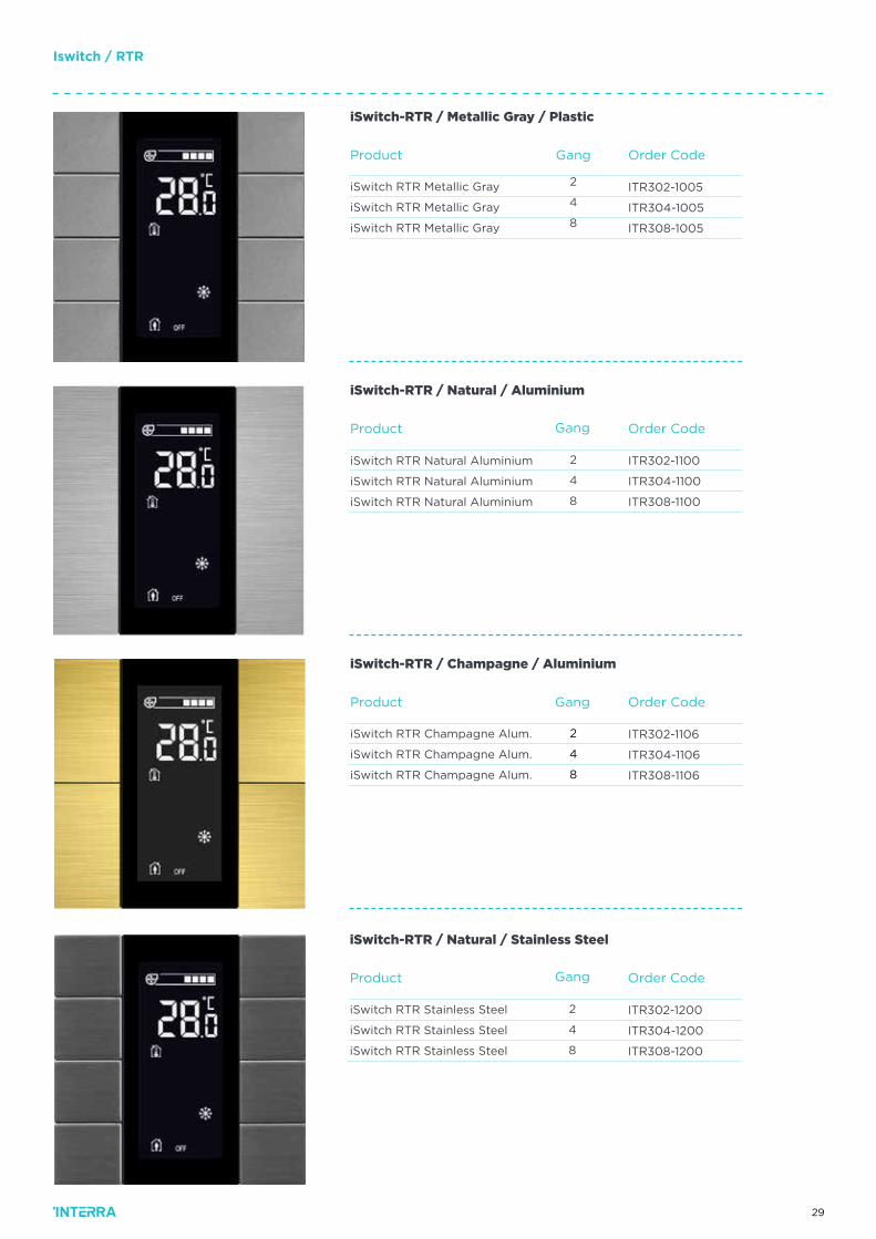
iSwitch-RTR / Metallic Gray / Plastic
Gang
Order CodeProduct
ITR302-1100
ITR304-1100
ITR308-1100
iSwitch RTR Natural Aluminium
iSwitch RTR Natural Aluminium
iSwitch RTR Natural Aluminium
2
4
8
iSwitch-RTR / Natural / Aluminium
Gang
Order CodeProduct
ITR302-1106
ITR304-1106
ITR308-1106
iSwitch RTR Champagne Alum.
iSwitch RTR Champagne Alum.
iSwitch RTR Champagne Alum.
2
4
8
iSwitch-RTR / Champagne / Aluminium
Gang
Order CodeProduct
ITR302-1200
ITR304-1200
ITR308-1200
iSwitch RTR Stainless Steel
iSwitch RTR Stainless Steel
iSwitch RTR Stainless Steel
2
4
8
iSwitch-RTR / Natural / Stainless Steel
Gang
30
Order CodeProduct
ITR302-1301
ITR304-1301
ITR308-1301
iSwitch Black GlassEF
iSwitch Black GlassEF
iSwitch Black GlassEF
2
4
8
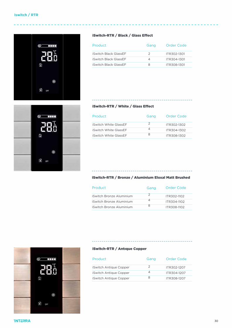
iSwitch-RTR / Black / Glass Effect
Gang
Order CodeProduct
ITR302-1302
ITR304-1302
ITR308-1302
iSwitch White GlassEF
iSwitch White GlassEF
iSwitch White GlassEF
2
4
8
iSwitch-RTR / White / Glass Effect
Order CodeProduct
ITR302-1102
ITR304-1102
ITR308-1102
iSwitch Bronze Aluminium
iSwitch Bronze Aluminium
iSwitch Bronze Aluminium
2
4
8
iSwitch-RTR / Bronze / Aluminium Eloxal Matt Brushed
Order CodeProduct
ITR302-1207
ITR304-1207
ITR308-1207
iSwitch Antique Copper
iSwitch Antique Copper
iSwitch Antique Copper
2
4
8
iSwitch-RTR / Antıque Copper
Gang
Gang
Gang
Iswitch / RTR
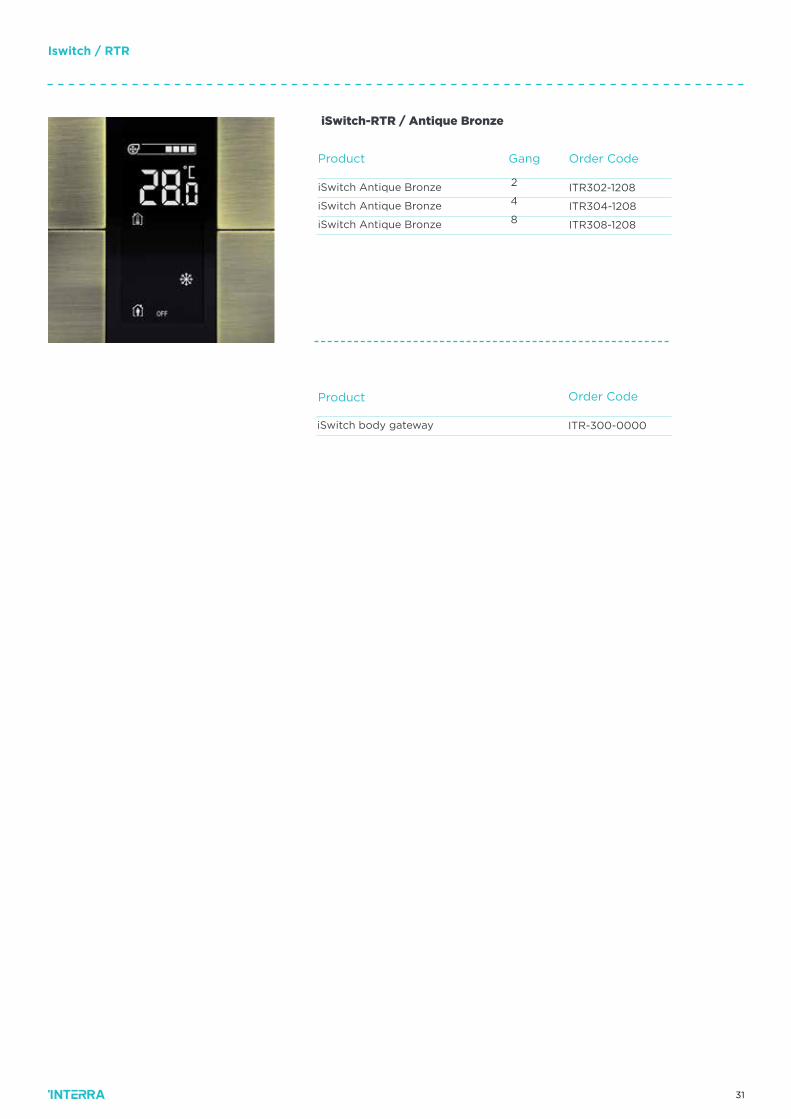
31
Iswitch / RTR
Order Code
ITR-300-0000iSwitch body gateway
Order CodeProduct
Product
ITR302-1208
ITR304-1208
ITR308-1208
iSwitch Antique Bronze
iSwitch Antique Bronze
iSwitch Antique Bronze
2
4
8
iSwitch-RTR / Antique Bronze
Gang
32
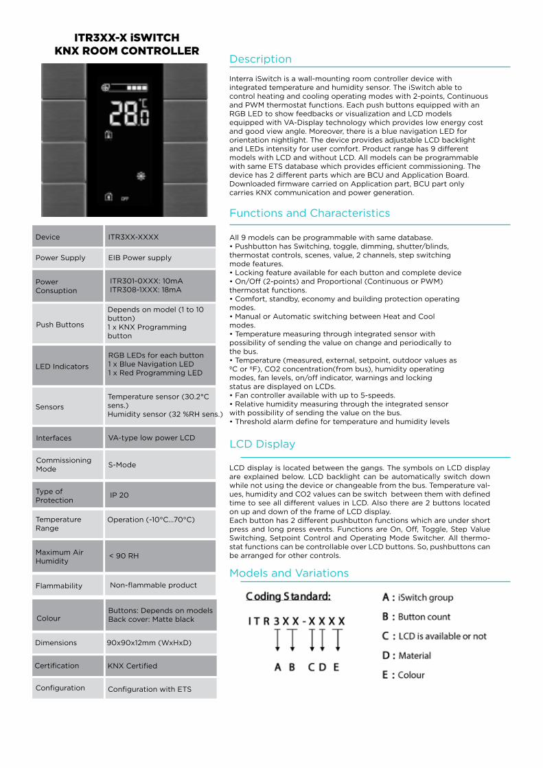
Description
Interra iSwitch is a wall-mounting room controller device withintegrated temperature and humidity sensor. The iSwitch able tocontrol heating and cooling operating modes with 2-points, Continuousand PWM thermostat functions. Each push buttons equipped with anRGB LED to show feedbacks or visualization and LCD modelsequipped with VA-Display technology which provides low energy costand good view angle. Moreover, there is a blue navigation LED fororientation nightlight. The device provides adjustable LCD backlightand LEDs intensity for user comfort. Product range has 9 differentmodels with LCD and without LCD. All models can be programmablewith same ETS database which provides efficient commissioning. Thedevice has 2 different parts which are BCU and Application Board.Downloaded firmware carried on Application part, BCU part onlycarries KNX communication and power generation.
Functions and Characteristics
All 9 models can be programmable with same database.• Pushbutton has Switching, toggle, dimming, shutter/blinds,thermostat controls, scenes, value, 2 channels, step switchingmode features.• Locking feature available for each button and complete device• On/Off (2-points) and Proportional (Continuous or PWM)thermostat functions.• Comfort, standby, economy and building protection operatingmodes.• Manual or Automatic switching between Heat and Coolmodes.• Temperature measuring through integrated sensor withpossibility of sending the value on change and periodically tothe bus.• Temperature (measured, external, setpoint, outdoor values asºC or ºF), CO2 concentration(from bus), humidity operatingmodes, fan levels, on/off indicator, warnings and lockingstatus are displayed on LCDs.• Fan controller available with up to 5-speeds.• Relative humidity measuring through the integrated sensorwith possibility of sending the value on the bus.• Threshold alarm define for temperature and humidity levels
LCD Display
LCD display is located between the gangs. The symbols on LCD display are explained below. LCD backlight can be automatically switch down while not using the device or changeable from the bus. Temperature val-ues, humidity and CO2 values can be switch between them with defined time to see all different values in LCD. Also there are 2 buttons located on up and down of the frame of LCD display. Each button has 2 different pushbutton functions which are under short press and long press events. Functions are On, Off, Toggle, Step Value Switching, Setpoint Control and Operating Mode Switcher. All thermo-stat functions can be controllable over LCD buttons. So, pushbuttons can be arranged for other controls.
Models and Variations
ITR3XX-X iSWITCHKNX ROOM CONTROLLER
Device ITR3XX-XXXX
Power Supply EIB Power supply
Power Consuption
ITR301-0XXX: 10mAITR308-1XXX: 18mA
Push Buttons
Depends on model (1 to 10 button)1 x KNX Programming button
LED Indicators
RGB LEDs for each button1 x Blue Navigation LED1 x Red Programming LED
Sensors
Temperature sensor (±0.2°C sens.)Humidity sensor (±2 %RH sens.)
Interfaces VA-type low power LCD
Commissioning Mode
S-Mode
Type of Protection
IP 20
Temperature Range
Operation (-10°C...70°C)
Maximum Air Humidity
< 90 RH
Flammability Non-flammable product
ColourButtons: Depends on modelsBack cover: Matte black
Dimensions
Configuration
Certification
90x90x12mm (WxHxD)
KNX Certified
Configuration with ETS
33
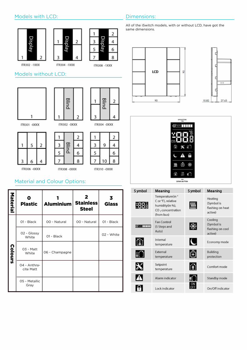
Models with LCD:
Models without LCD:
Material and Colour Options:
Ma
teria
lC
olo
urs
0Plastic
1Aluminium
2Stainless
Steel
3Glass
01 - Black 00 - Natural 00 - Natural 01 - Black
02 - GlossyWhite
03 - MattWhite
04 - Anthra-cite Matt
05 - MetallicGray
01 - Black
06 - Champagne
02 - White
Dimensions:
All of the iSwitch models, with or without LCD, have got the same dimensions.
34
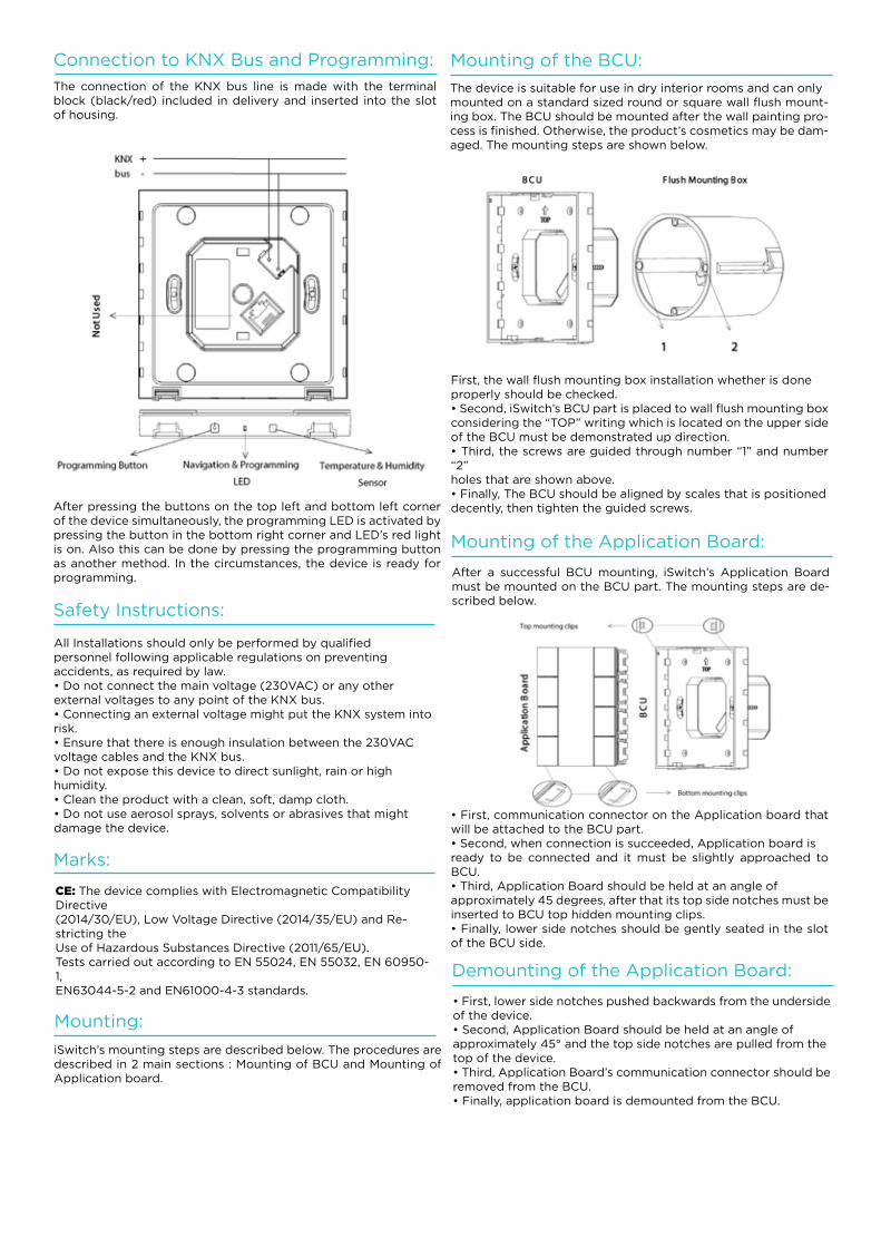
Connection to KNX Bus and Programming:
The connection of the KNX bus line is made with the terminal block (black/red) included in delivery and inserted into the slot of housing.
After pressing the buttons on the top left and bottom left corner of the device simultaneously, the programming LED is activated by pressing the button in the bottom right corner and LED’s red light is on. Also this can be done by pressing the programming button as another method. In the circumstances, the device is ready for programming.
Mounting:
Mounting of the BCU:
Safety Instructions:
Marks:
iSwitch’s mounting steps are described below. The procedures are described in 2 main sections : Mounting of BCU and Mounting of Application board.
The device is suitable for use in dry interior rooms and can onlymounted on a standard sized round or square wall flush mount-ing box. The BCU should be mounted after the wall painting pro-cess is finished. Otherwise, the product’s cosmetics may be dam-aged. The mounting steps are shown below.
All Installations should only be performed by qualifiedpersonnel following applicable regulations on preventingaccidents, as required by law.• Do not connect the main voltage (230VAC) or any otherexternal voltages to any point of the KNX bus.• Connecting an external voltage might put the KNX system intorisk.• Ensure that there is enough insulation between the 230VACvoltage cables and the KNX bus.• Do not expose this device to direct sunlight, rain or highhumidity.• Clean the product with a clean, soft, damp cloth.• Do not use aerosol sprays, solvents or abrasives that mightdamage the device.
CE: The device complies with Electromagnetic Compatibility Directive(2014/30/EU), Low Voltage Directive (2014/35/EU) and Re-stricting theUse of Hazardous Substances Directive (2011/65/EU).Tests carried out according to EN 55024, EN 55032, EN 60950-1,EN63044-5-2 and EN61000-4-3 standards.
First, the wall flush mounting box installation whether is doneproperly should be checked.• Second, iSwitch’s BCU part is placed to wall flush mounting boxconsidering the “TOP” writing which is located on the upper sideof the BCU must be demonstrated up direction.• Third, the screws are guided through number “1” and number “2”holes that are shown above.• Finally, The BCU should be aligned by scales that is positioneddecently, then tighten the guided screws.
Mounting of the Application Board:
Demounting of the Application Board:
After a successful BCU mounting, iSwitch’s Application Board must be mounted on the BCU part. The mounting steps are de-scribed below.
• First, lower side notches pushed backwards from the undersideof the device.• Second, Application Board should be held at an angle ofapproximately 45° and the top side notches are pulled from thetop of the device.• Third, Application Board’s communication connector should beremoved from the BCU.• Finally, application board is demounted from the BCU.
• First, communication connector on the Application board that will be attached to the BCU part.• Second, when connection is succeeded, Application board isready to be connected and it must be slightly approached to BCU.• Third, Application Board should be held at an angle ofapproximately 45 degrees, after that its top side notches must be inserted to BCU top hidden mounting clips.• Finally, lower side notches should be gently seated in the slot of the BCU side.
35
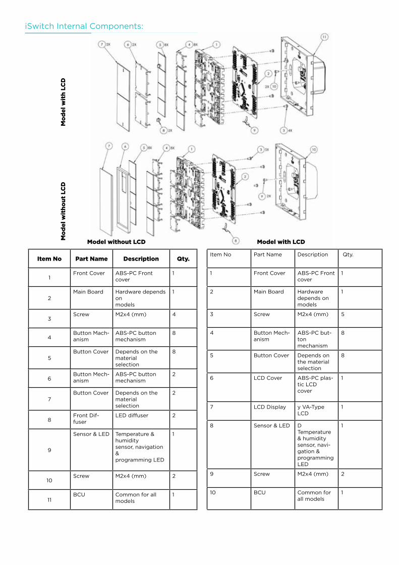
iSwitch Internal Components:
Mo
de
l w
ith
LC
DM
od
el
wit
ho
ut
LC
D
Item No Part Name Description Qty.
1Front Cover ABS-PC Front
cover1
2Main Board Hardware depends
onmodels
1
3Screw M2x4 (mm) 4
4Button Mach-anism
ABS-PC buttonmechanism
8
5Button Cover Depends on the
materialselection
8
6Button Mech-anism
ABS-PC buttonmechanism
2
7Button Cover Depends on the
materialselection
2
8Front Dif-fuser
LED diffuser 2
9
Sensor & LED Temperature & humiditysensor, navigation &programming LED
1
10Screw M2x4 (mm) 2
11BCU Common for all
models1
Model without LCD Model with LCD
Item No Part Name Description Qty.
1 Front Cover ABS-PC Front cover
1
2 Main Board Hardware depends onmodels
1
3 Screw M2x4 (mm) 5
4 Button Mech-anism
ABS-PC but-tonmechanism
8
5 Button Cover Depends on the materialselection
8
6 LCD Cover ABS-PC plas-tic LCDcover
1
7 LCD Display y VA-Type LCD
1
8 Sensor & LED DTemperature & humiditysensor, navi-gation &programming LED
1
9 Screw M2x4 (mm) 2
10 BCU Common for all models
1
36
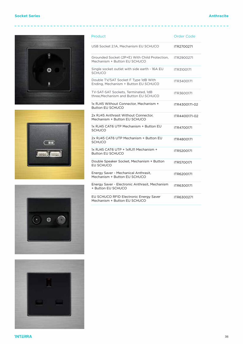
Order CodeProduct
USB Socket 2.1A, Mechanism EU SCHUCO
Grounded Socket (2P+E) With Child Protection,Mechanism + Button EU SCHUCO
Socket Series Anthracite
Single socket outlet with side earth - 16A EU SCHUCO
Double TV/SAT Socket F Type 1dB With Ending, Mechanism + Button EU SCHUCO
TV-SAT-SAT Sockets, Terminated, 1dB three,Mechanism and Button EU SCHUCO
1x RJ45 Without Connector, Mechanism + Button EU SCHUCO
2x RJ45 Anthrasit Without Connector, Mechanism + Button EU SCHUCO
1x RJ45 CAT6 UTP Mechanism + Button EU SCHUCO
2x RJ45 CAT6 UTP Mechanism + Button EU SCHUCO
1x RJ45 CAT6 UTP + 1xRJ11 Mechanism + Button EU SCHUCO
Double Speaker Socket, Mechanism + Button EU SCHUCO
Energy Saver - Mechanical Anthrasit, Mechanism + Button EU SCHUCO
Energy Saver - Electronic Anthrasit, Mechanism + Button EU SCHUCO
EU SCHUCO RFID Electronic Energy Saver Mechanism + Button EU SCHUCO
ITR4300171-02
ITR4400171-02
ITR4700171
ITR4800171
ITR5200171
ITR5700171
ITR6200171
ITR6300171
ITR6300271
ITR3600171
ITR3400171
ITR3100171
ITR2900271
ITR2700271
37
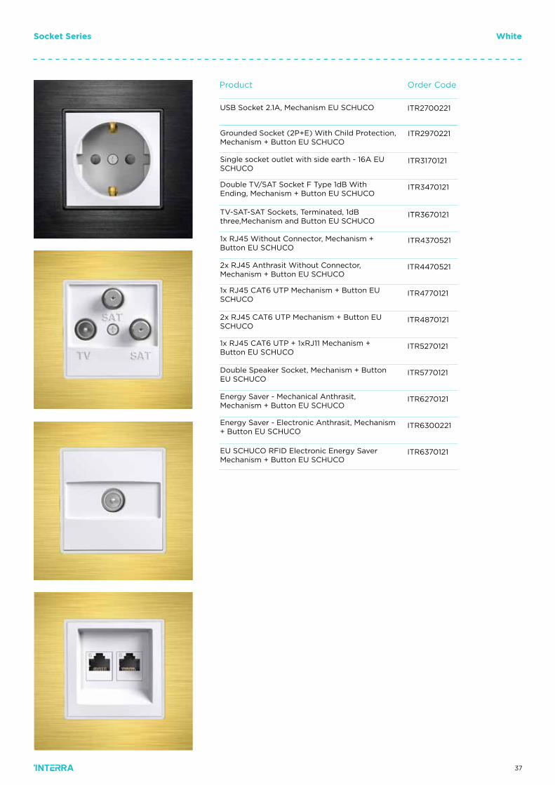
Socket Series White
Order CodeProduct
USB Socket 2.1A, Mechanism EU SCHUCO
Grounded Socket (2P+E) With Child Protection,Mechanism + Button EU SCHUCO
Single socket outlet with side earth - 16A EU SCHUCO
Double TV/SAT Socket F Type 1dB With Ending, Mechanism + Button EU SCHUCO
TV-SAT-SAT Sockets, Terminated, 1dB three,Mechanism and Button EU SCHUCO
1x RJ45 Without Connector, Mechanism + Button EU SCHUCO
2x RJ45 Anthrasit Without Connector, Mechanism + Button EU SCHUCO
1x RJ45 CAT6 UTP Mechanism + Button EU SCHUCO
2x RJ45 CAT6 UTP Mechanism + Button EU SCHUCO
1x RJ45 CAT6 UTP + 1xRJ11 Mechanism + Button EU SCHUCO
Double Speaker Socket, Mechanism + Button EU SCHUCO
Energy Saver - Mechanical Anthrasit, Mechanism + Button EU SCHUCO
Energy Saver - Electronic Anthrasit, Mechanism + Button EU SCHUCO
EU SCHUCO RFID Electronic Energy Saver Mechanism + Button EU SCHUCO
ITR4370521
ITR4470521
ITR4770121
ITR4870121
ITR5270121
ITR5770121
ITR6270121
ITR6300221
ITR6370121
ITR3670121
ITR3470121
ITR3170121
ITR2970221
ITR2700221
38
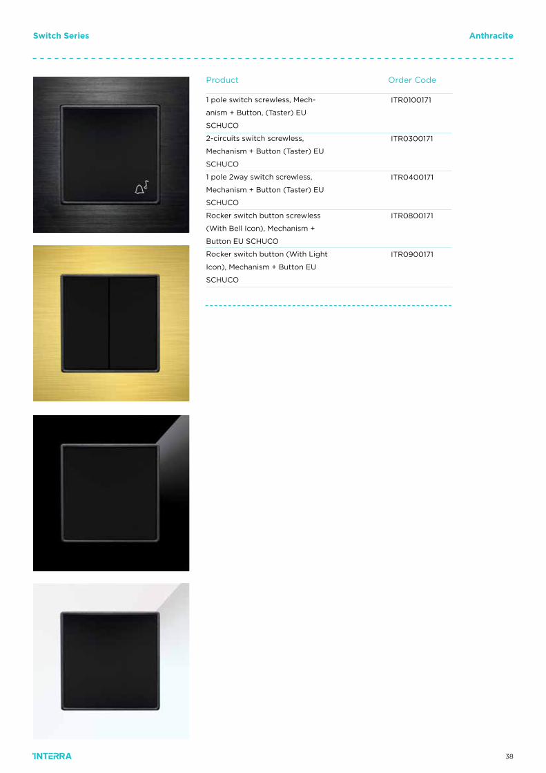
Order CodeProduct
ITR0100171
ITR0300171
ITR0400171
ITR0800171
ITR0900171
1 pole switch screwless, Mech-
anism + Button, (Taster) EU
SCHUCO
2-circuits switch screwless,
Mechanism + Button (Taster) EU
SCHUCO
1 pole 2way switch screwless,
Mechanism + Button (Taster) EU
SCHUCO
Rocker switch button screwless
(With Bell Icon), Mechanism +
Button EU SCHUCO
Rocker switch button (With Light
Icon), Mechanism + Button EU
SCHUCO
Switch Series Anthracite
39
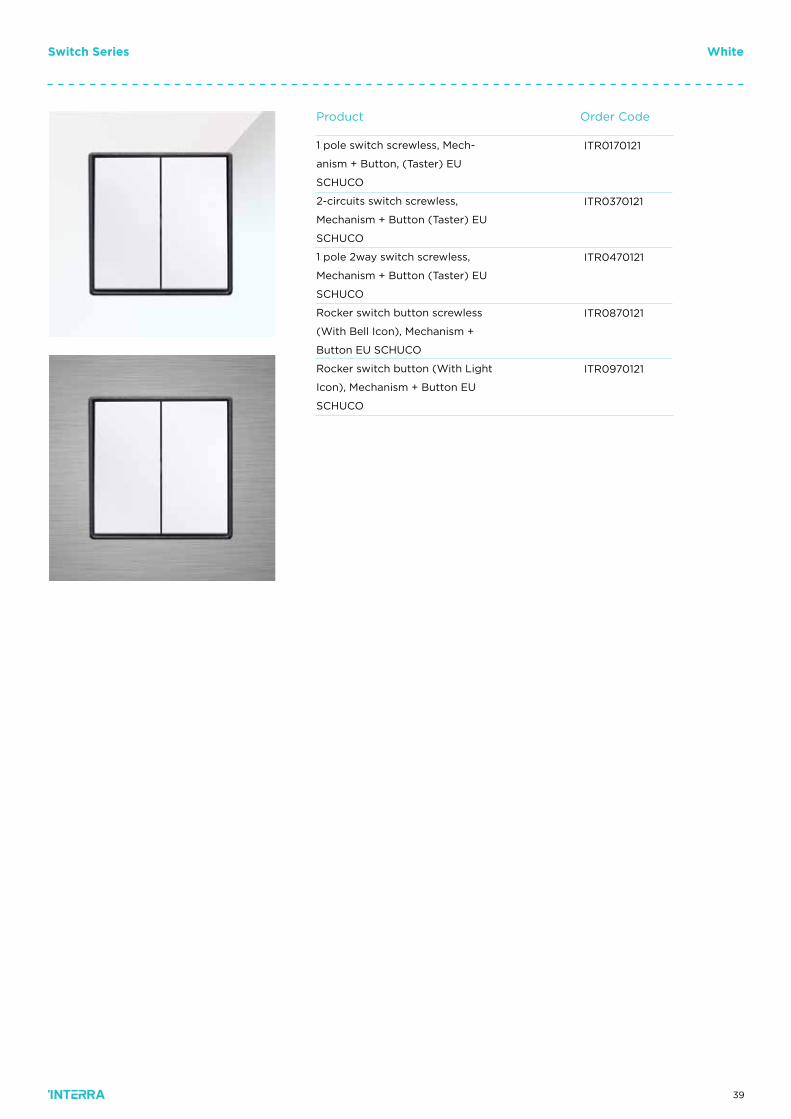
Switch Series White
Order CodeProduct
ITR0170121
ITR0370121
ITR0470121
ITR0870121
ITR0970121
1 pole switch screwless, Mech-
anism + Button, (Taster) EU
SCHUCO
2-circuits switch screwless,
Mechanism + Button (Taster) EU
SCHUCO
1 pole 2way switch screwless,
Mechanism + Button (Taster) EU
SCHUCO
Rocker switch button screwless
(With Bell Icon), Mechanism +
Button EU SCHUCO
Rocker switch button (With Light
Icon), Mechanism + Button EU
SCHUCO
40
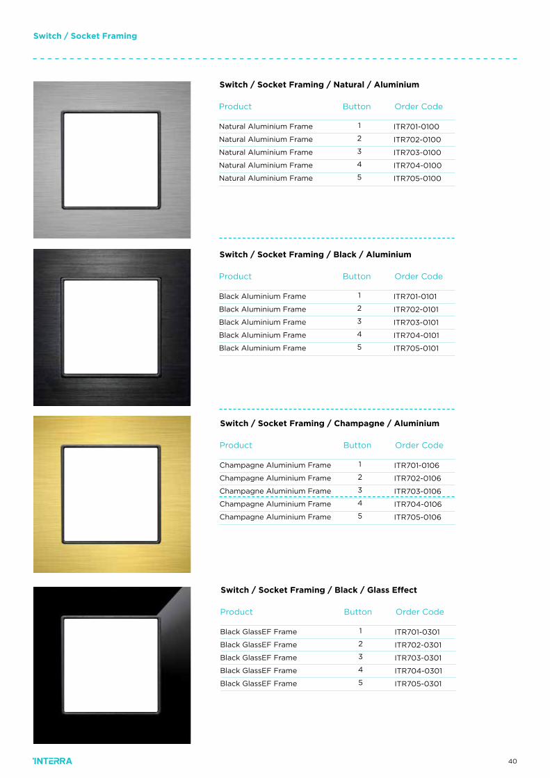
Order CodeProduct
ITR701-0100
ITR702-0100
ITR703-0100
ITR704-0100
ITR705-0100
Natural Aluminium Frame
Natural Aluminium Frame
Natural Aluminium Frame
Natural Aluminium Frame
Natural Aluminium Frame
Switch / Socket Framing / Natural / Aluminium
Switch / Socket Framing
Button
1
2
3
4
5
Order CodeProduct
ITR701-0101
ITR702-0101
ITR703-0101
ITR704-0101
ITR705-0101
Black Aluminium Frame
Black Aluminium Frame
Black Aluminium Frame
Black Aluminium Frame
Black Aluminium Frame
Switch / Socket Framing / Black / Aluminium
Button
1
2
3
4
5
Order CodeProduct
ITR701-0106
ITR702-0106
ITR703-0106
ITR704-0106
ITR705-0106
Champagne Aluminium Frame
Champagne Aluminium Frame
Champagne Aluminium Frame
Champagne Aluminium Frame
Champagne Aluminium Frame
Switch / Socket Framing / Champagne / Aluminium
Button
1
2
3
4
5
Order CodeProduct
ITR701-0301
ITR702-0301
ITR703-0301
ITR704-0301
ITR705-0301
Black GlassEF Frame
Black GlassEF Frame
Black GlassEF Frame
Black GlassEF Frame
Black GlassEF Frame
Switch / Socket Framing / Black / Glass Effect
Button
1
2
3
4
5
41
Switch / Socket Framing
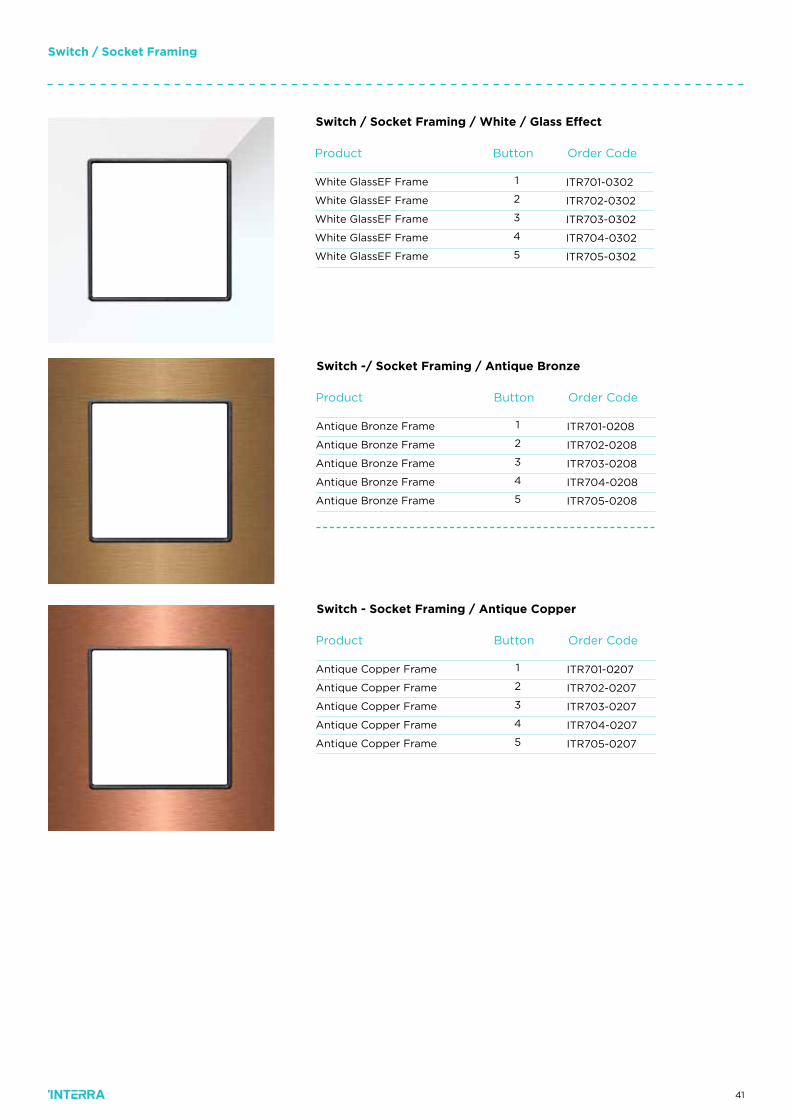
Order CodeProduct
ITR701-0208
ITR702-0208
ITR703-0208
ITR704-0208
ITR705-0208
Antique Bronze Frame
Antique Bronze Frame
Antique Bronze Frame
Antique Bronze Frame
Antique Bronze Frame
Switch -/ Socket Framing / Antique Bronze
Button
1
2
3
4
5
Order CodeProduct
ITR701-0207
ITR702-0207
ITR703-0207
ITR704-0207
ITR705-0207
Antique Copper Frame
Antique Copper Frame
Antique Copper Frame
Antique Copper Frame
Antique Copper Frame
Switch - Socket Framing / Antique Copper
Button
1
2
3
4
5
Order CodeProduct
ITR701-0302
ITR702-0302
ITR703-0302
ITR704-0302
ITR705-0302
White GlassEF Frame
White GlassEF Frame
White GlassEF Frame
White GlassEF Frame
White GlassEF Frame
Switch / Socket Framing / White / Glass Effect
Button
1
2
3
4
5
42
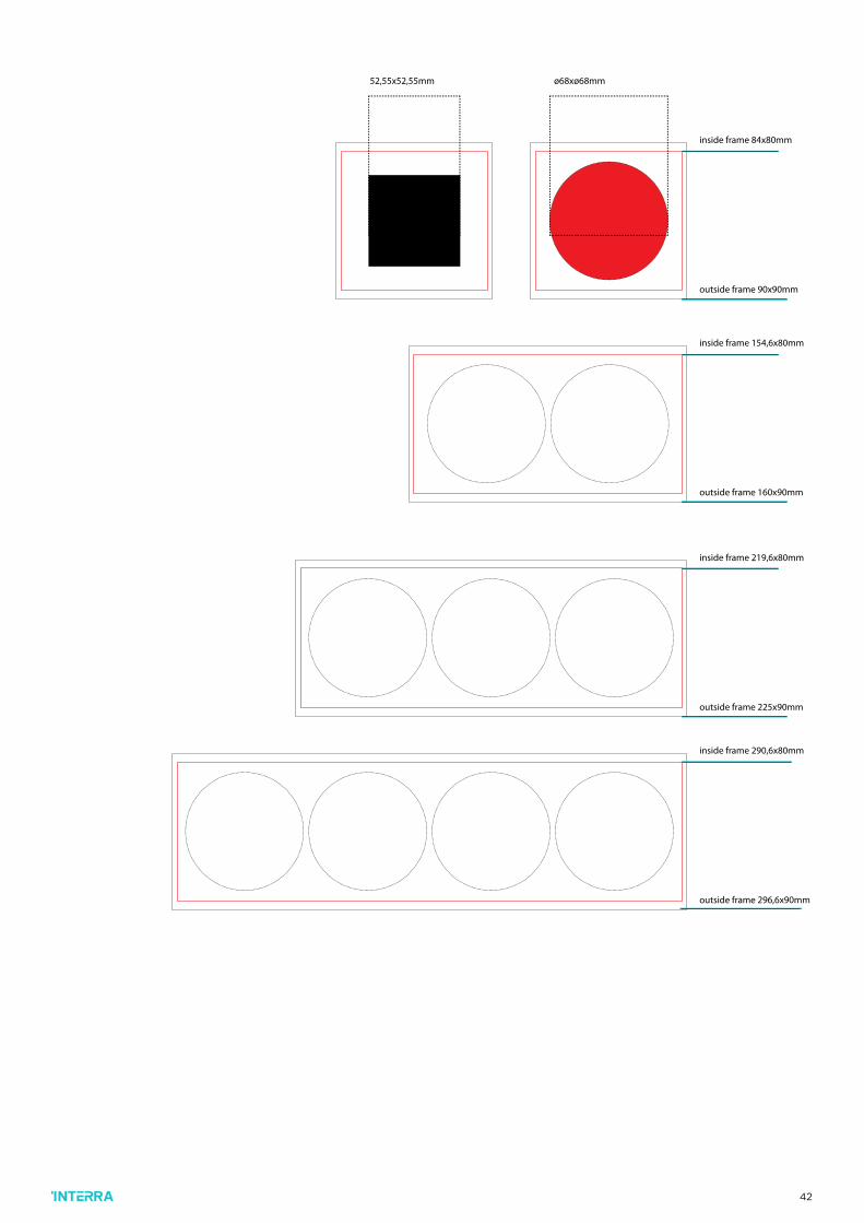
52,55x52,55mm ø68xø68mm
inside frame 84x80mm
outside frame 90x90mm
inside frame 154,6x80mm
outside frame 160x90mm
inside frame 219,6x80mm
outside frame 225x90mm
inside frame 290,6x80mm
outside frame 296,6x90mm
43
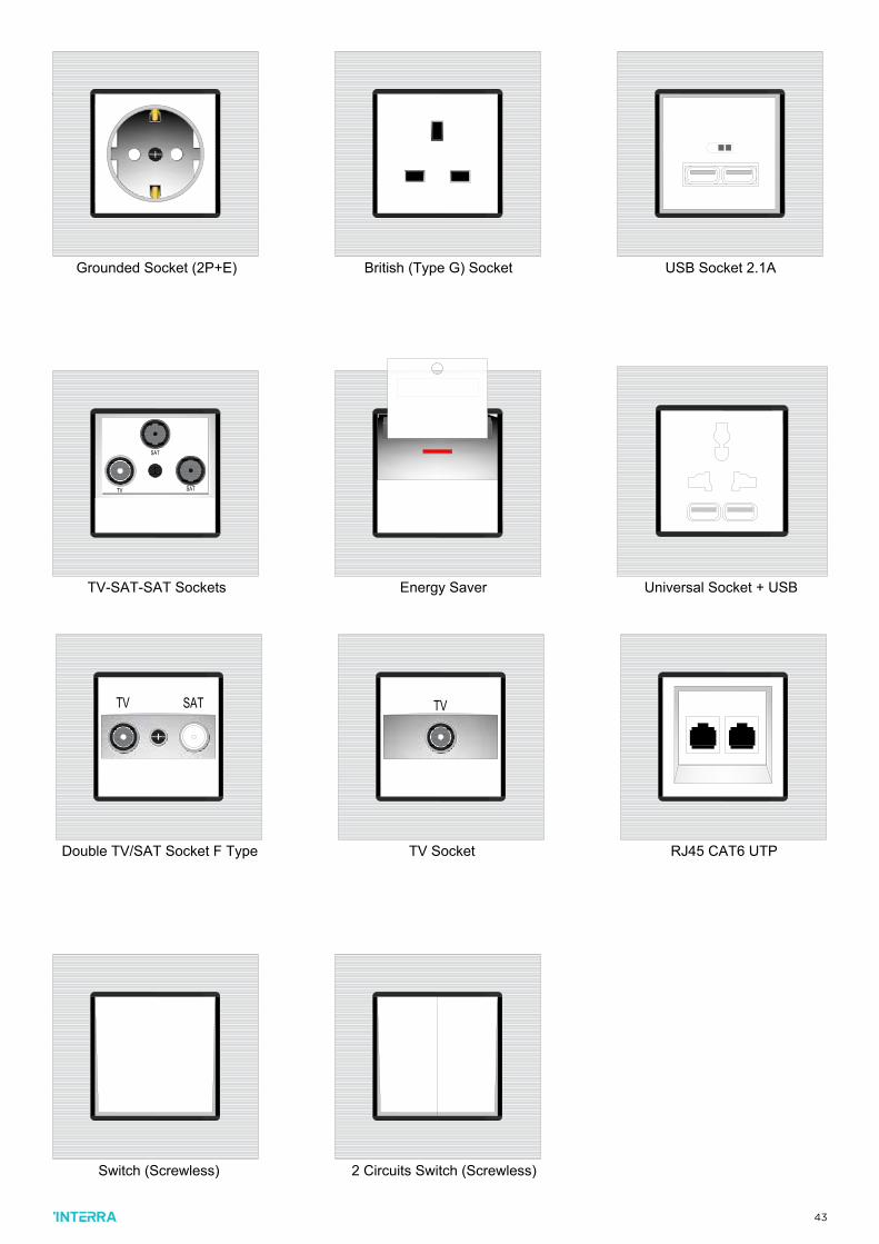
Grounded Socket (2P+E) British (Type G) Socket USB Socket 2.1A
TV SAT
Double TV/SAT Socket F Type
TV
TV Socket RJ45 CAT6 UTP
SAT
SATTV
TV-SAT-SAT Sockets Energy Saver Universal Socket + USB Switch (Screwless) 2 Circuits Switch (Screwless)
Grounded Socket (2P+E) British (Type G) Socket USB Socket 2.1A
TV SAT
Double TV/SAT Socket F Type
TV
TV Socket RJ45 CAT6 UTP
SAT
SATTV
TV-SAT-SAT Sockets Energy Saver Universal Socket + USB Switch (Screwless) 2 Circuits Switch (Screwless)
44
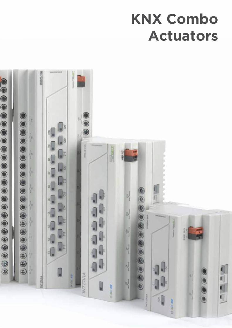
KNX Combo Actuators
45
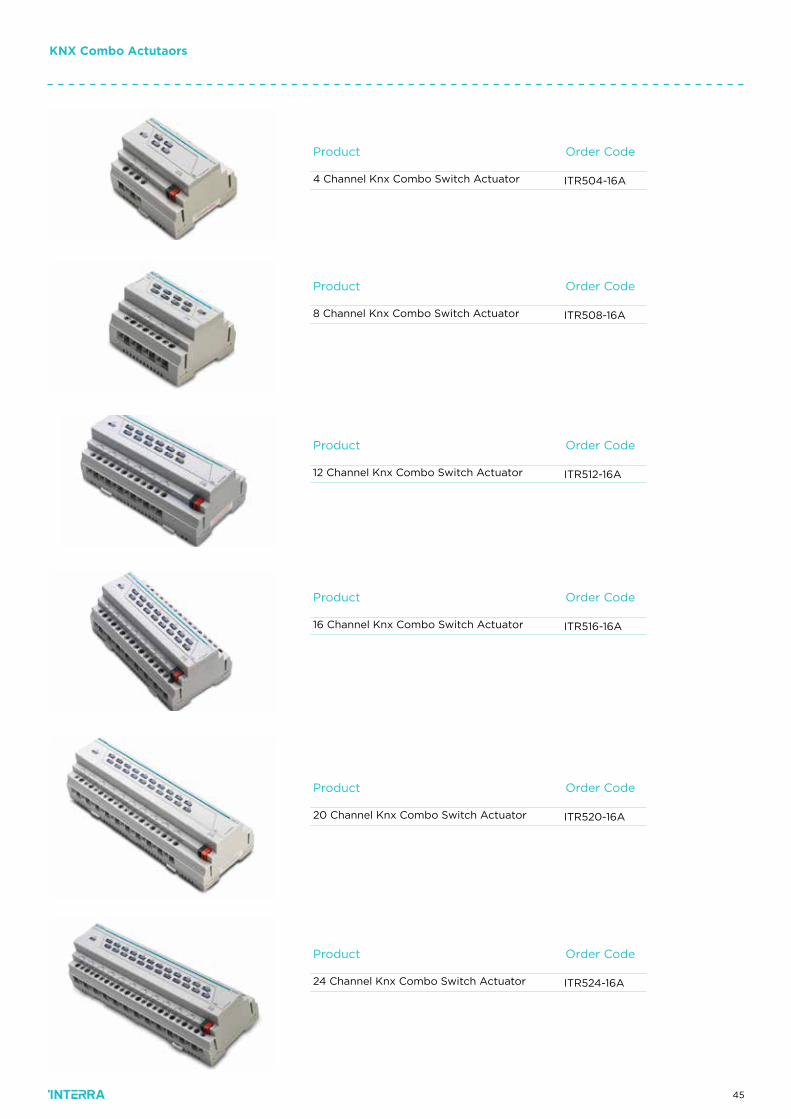
KNX Combo Actutaors
Order Code
Order Code
Order Code
Order Code
Order Code
Product
Product
Product
Product
Product
ITR508-16A
ITR512-16A
ITR516-16A
ITR520-16A
ITR524-16A
Order CodeProduct
ITR504-16A4 Channel Knx Combo Switch Actuator
8 Channel Knx Combo Switch Actuator
12 Channel Knx Combo Switch Actuator
16 Channel Knx Combo Switch Actuator
20 Channel Knx Combo Switch Actuator
24 Channel Knx Combo Switch Actuator
46
KNX Combo Actutaors
Power Supply
CurrentConsumption
Number of Outputs
Commisioning Mode
Type of Protection
TemperatureRange
Flammability
Colour
Dimensions
ITR500-001
EIB Power Supply
Max. 20mA
4, 8, 12, 16, 20 or 24
S-Mode
IP 20
Operation (-5°C...45°C)
Storage (-20°C...60°C)
Non-flammable product
Light Gray and white
105x90x64mm(WxHxD)-> 6 DIN units
171x90x64mm(WxHxD)->10 DIN units
274x90x64mm(WxHxD)->15 DIN units
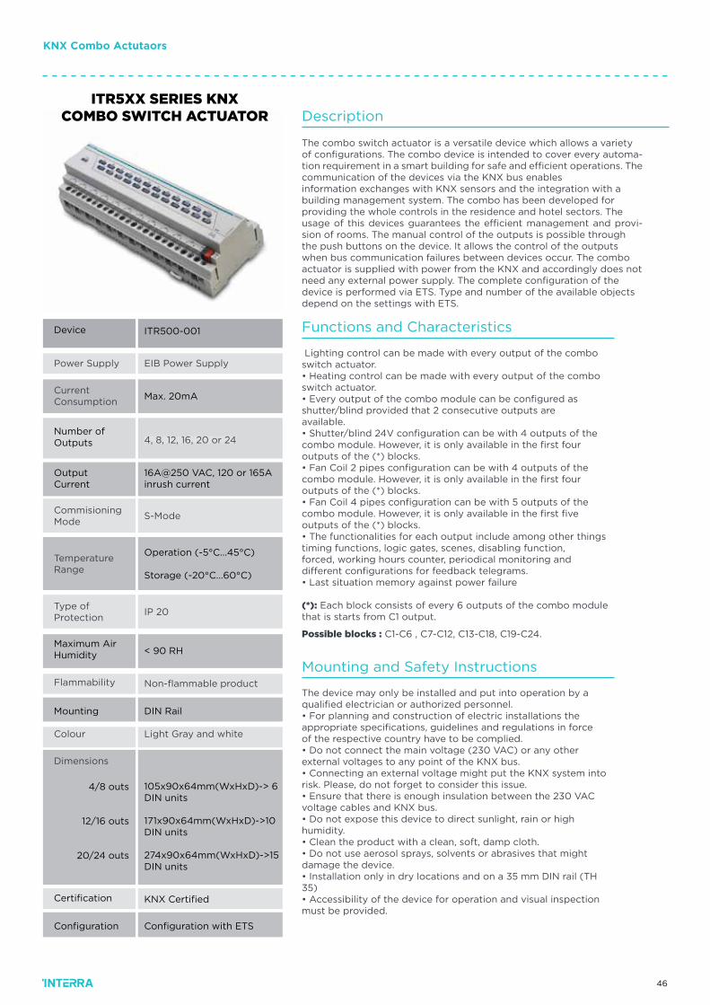
Device
ITR5XX SERIES KNX COMBO SWITCH ACTUATOR
Certification
Configuration
KNX Certified
Configuration with ETS
Output Current
16A@250 VAC, 120 or 165A inrush current
Maximum AirHumidity
Mounting
< 90 RH
DIN Rail
4/8 outs
12/16 outs
20/24 outs
Functions and Characteristics
Mounting and Safety Instructions
Lighting control can be made with every output of the comboswitch actuator.• Heating control can be made with every output of the comboswitch actuator.• Every output of the combo module can be configured asshutter/blind provided that 2 consecutive outputs areavailable.• Shutter/blind 24V configuration can be with 4 outputs of thecombo module. However, it is only available in the first fouroutputs of the (*) blocks.• Fan Coil 2 pipes configuration can be with 4 outputs of thecombo module. However, it is only available in the first fouroutputs of the (*) blocks.• Fan Coil 4 pipes configuration can be with 5 outputs of thecombo module. However, it is only available in the first fiveoutputs of the (*) blocks.• The functionalities for each output include among other thingstiming functions, logic gates, scenes, disabling function,forced, working hours counter, periodical monitoring anddifferent configurations for feedback telegrams.• Last situation memory against power failure
(*): Each block consists of every 6 outputs of the combo modulethat is starts from C1 output.
Possible blocks : C1-C6 , C7-C12, C13-C18, C19-C24.
The device may only be installed and put into operation by aqualified electrician or authorized personnel.• For planning and construction of electric installations theappropriate specifications, guidelines and regulations in forceof the respective country have to be complied.• Do not connect the main voltage (230 VAC) or any otherexternal voltages to any point of the KNX bus.• Connecting an external voltage might put the KNX system intorisk. Please, do not forget to consider this issue.• Ensure that there is enough insulation between the 230 VACvoltage cables and KNX bus.• Do not expose this device to direct sunlight, rain or highhumidity.• Clean the product with a clean, soft, damp cloth.• Do not use aerosol sprays, solvents or abrasives that mightdamage the device.• Installation only in dry locations and on a 35 mm DIN rail (TH35)• Accessibility of the device for operation and visual inspectionmust be provided.
Description
The combo switch actuator is a versatile device which allows a varietyof configurations. The combo device is intended to cover every automa-tion requirement in a smart building for safe and efficient operations. The communication of the devices via the KNX bus enablesinformation exchanges with KNX sensors and the integration with abuilding management system. The combo has been developed forproviding the whole controls in the residence and hotel sectors. Theusage of this devices guarantees the efficient management and provi-sion of rooms. The manual control of the outputs is possible throughthe push buttons on the device. It allows the control of the outputswhen bus communication failures between devices occur. The comboactuator is supplied with power from the KNX and accordingly does notneed any external power supply. The complete configuration of thedevice is performed via ETS. Type and number of the available objectsdepend on the settings with ETS.
47
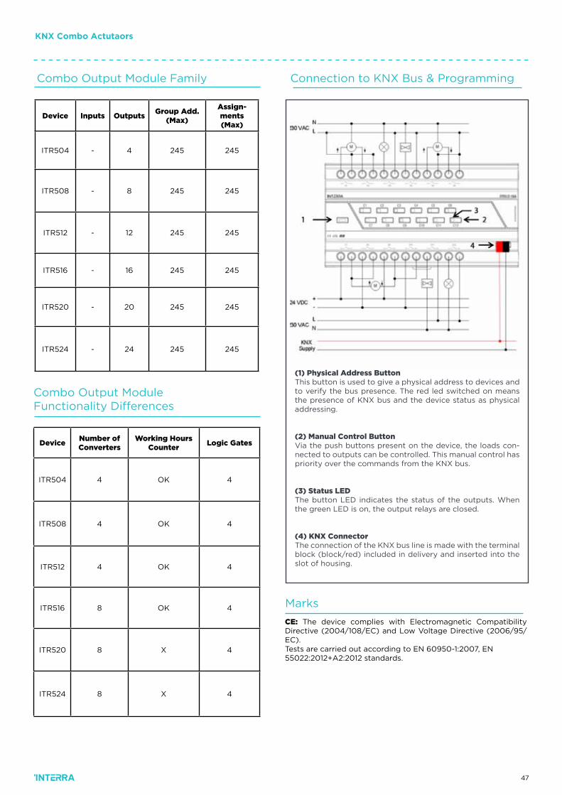
(1) Physical Address ButtonThis button is used to give a physical address to devices and to verify the bus presence. The red led switched on means the presence of KNX bus and the device status as physical addressing.
(2) Manual Control Button Via the push buttons present on the device, the loads con-nected to outputs can be controlled. This manual control has priority over the commands from the KNX bus.
(3) Status LED The button LED indicates the status of the outputs. When the green LED is on, the output relays are closed.
(4) KNX ConnectorThe connection of the KNX bus line is made with the terminal block (block/red) included in delivery and inserted into the slot of housing.
Combo Output Module Family Connection to KNX Bus & Programming
Combo Output Module Functionality Differences
Device Inputs OutputsGroup Add.
(Max)
Assign-ments(Max)
ITR504 - 4 245 245
ITR508 - 8 245 245
ITR512 - 12 245 245
ITR516 - 16 245 245
ITR520 - 20 245 245
ITR524 - 24 245 245
DeviceNumber ofConverters
Working HoursCounter
Logic Gates
ITR504 4 OK 4
ITR508 4 OK 4
ITR512 4 OK 4
ITR516 8 OK 4
ITR520 8 X 4
ITR524 8 X 4
Marks
CE: The device complies with Electromagnetic Compatibility Directive (2004/108/EC) and Low Voltage Directive (2006/95/EC).Tests are carried out according to EN 60950-1:2007, EN55022:2012+A2:2012 standards.
KNX Combo Actutaors
48
Power Supply
CurrentConsumption
Dimming Output
Type of Protection
Maximum AirHumidity
TemperatureRange
Flammability
Colour
Dimensions
ITR500-001
EIB Power Supply
10mA
24mA @ 0-10V DC per channel
IP 20
<90RH
Operation (-5°C...45°C)
Storage (-20°C...60°C)
Non-flammable product
Light Gray
90x216x66 mm (HxWxD)
Device
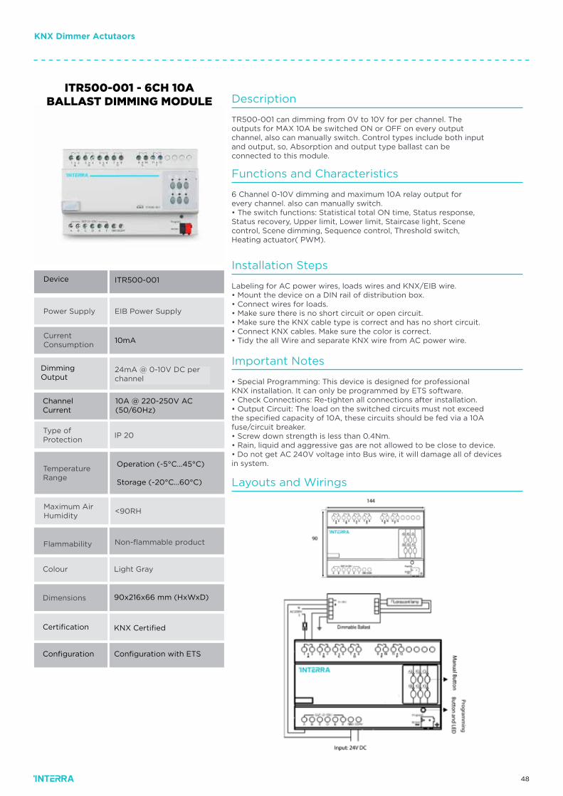
ITR500-001 - 6CH 10A BALLAST DIMMING MODULE
Certification
Configuration
KNX Certified
Configuration with ETS
Channel Current
10A @ 220-250V AC (50/60Hz)
Description
TR500-001 can dimming from 0V to 10V for per channel. Theoutputs for MAX 10A be switched ON or OFF on every outputchannel, also can manually switch. Control types include both inputand output, so, Absorption and output type ballast can beconnected to this module.
Functions and Characteristics
6 Channel 0-10V dimming and maximum 10A relay output forevery channel. also can manually switch.• The switch functions: Statistical total ON time, Status response,Status recovery, Upper limit, Lower limit, Staircase light, Scenecontrol, Scene dimming, Sequence control, Threshold switch,Heating actuator( PWM).
Installation Steps
Layouts and Wirings
Labeling for AC power wires, loads wires and KNX/EIB wire.• Mount the device on a DIN rail of distribution box.• Connect wires for loads.• Make sure there is no short circuit or open circuit.• Make sure the KNX cable type is correct and has no short circuit.• Connect KNX cables. Make sure the color is correct.• Tidy the all Wire and separate KNX wire from AC power wire.
Important Notes
• Special Programming: This device is designed for professionalKNX installation. It can only be programmed by ETS software.• Check Connections: Re-tighten all connections after installation.• Output Circuit: The load on the switched circuits must not exceedthe specified capacity of 10A, these circuits should be fed via a 10Afuse/circuit breaker.• Screw down strength is less than 0.4Nm.• Rain, liquid and aggressive gas are not allowed to be close to device.• Do not get AC 240V voltage into Bus wire, it will damage all of devicesin system.
KNX Dimmer Actutaors
49
Power Supply
CurrentConsumption
Dimming Power
Type of Protection
Maximum AirHumidity
TemperatureRange
Flammability
Colour
Dimensions
ITR500-002
EIB Power Supply
10mA
1.5A max @ 120-240V AC
IP 20
<90RH
Operation (-5°C...45°C)
Storage (-20°C...60°C)
Non-flammable product
Light Gray
90x216x66 mm (HxWxD)
Device
ITR500-002 - 4CH 1.5A UNIVERSAL DIMMING MODULE
Certification
Configuration
KNX Certified
Configuration with ETS
Description
ITR500-002 has 4 channel 1.5A dimming capability. It has short circuit,over load and heat protection.
Functions and Characteristics
• The Dimmer Module can dimming for 4 channels independentloads.• Leading Edge dimming or Trailing Edge dimming for dimmer.• Parallel channels to form a larger current output.• The dimmers may be used for dimming ordinary incandescentlamps, low voltage halogen lamps and other light sources whichsupport leading or trailing edge technology .• The module functions: Statistics total ON time, Status response,Status recovery, Over temperature protection, Read temperature,Over temperature alarm, Staircase light, Flashing light, Scenecontrol, Scene dimming, Sequence control, Threshold control,Heating actuator (PWM).• Short circuit protection, over load protection, over Heat protection.
Installation Steps
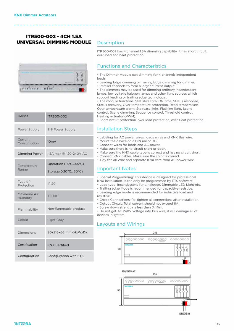
Layouts and Wirings
• Labeling for AC power wires, loads wires and KNX Bus wire.• Mount the device on a DIN rail of DB.• Connect wires for loads and AC power.• Make sure there is no circuit short or open.• Make sure the KNX cable type is correct and has no circuit short.• Connect KNX cables. Make sure the color is correct.• Tidy the all Wire and separate KNX wire from AC power wire.
Important Notes
• Special Programming: This device is designed for professionalKNX installation. It can only be programmed by ETS software.• Load type: Incandescent light, halogen, Dimmable LED Light etc.• Trailing edge Mode is recommended for capacitive resistive.• Leading edge mode is recommended for inductive load andresistive.• Check Connections: Re-tighten all connections after installation.• Output Circuit: Total current should not exceed 6A.• Screw down strength is less than 0.4Nm.• Do not get AC 240V voltage into Bus wire, it will damage all ofdevices in system.
KNX Dimmer Actutaors

50
KNX Gateway KNX DALI GatewayKNX DALIGatewayKNX 1x64/2x64 Tunable - White &Color Control
51
Order CodeProduct
ITR110-0104
ITR110-1104
KNX 1x64 Tunable - White & Color Control
KNX 2x64 Tunable - White & Color Control
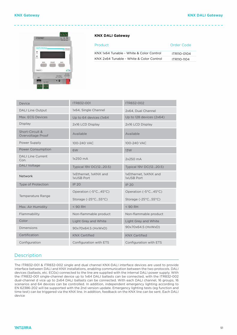
KNX DALI Gateway
KNX DALI GatewayKNX Gateway
Device
DALI Line Output 1x64, Single Channel
ITR832-001 ITR832-002
2x64, Dual Channel
Max. ECG Devices Up to 64 devices (1x64 Up to 128 devices (2x64)
Display 2x16 LCD Display 2x16 LCD Display
Short-Circuit &Overvoltage Proof
Available Available
Power Supply 100-240 VAC 100-240 VAC
Power Consumption 6W 13W
DALI Line CurrentCon. 1x250 mA 2x250 mA
DALI Voltage Typical 19V DC(12...20.5) Typical 19V DC(12...20.5)
Network1xEthernet, 1xKNX and1xUSB Port
1xEthernet, 1xKNX and1xUSB Port
Type of Protection IP 20 IP 20
Temperature Range
Operation (-5°C...45°C)
Storage (-25°C...55°C)
Operation (-5°C...45°C)
Storage (-25°C...55°C)
Max. Air Humidity < 90 RH < 90 RH
Flammability Non-flammable product Non-flammable product
Color Light Grey and White Light Grey and White
Certification
Configuration
KNX Certified KNX Certified
Configuration with ETS Configuration with ETS
Dimensions 90x70x64.5 (HxWxD) 90x70x64.5 (HxWxD)
Description
The ITR832-001 & ITR832-002 single and dual channel KNX-DALI interface devices are used to provide interface between DALI and KNX installations, enabling communication between the two protocols. DALI devices (ballasts, etc. ECGs) connected to the line are supplied with the internal DALI power supply. With the ITR832-001 single-channel device up to 1x64 DALI ballasts can be connected, with the ITR832-002 dual-channel d vice up to 2x64 DALI ballasts can be connected. With each DALI channel, 16 groups, 16 scenarios and 64 devices can be controlled. In addition, independent emergency lighting according to EN 62386-202 will be supported with the 2nd version update. Emergency lighting tests (eg function and time test) can be triggered via the KNX line. In addition, feedback on the KNX line can be sent. Each DALI device
52
KNX DALI GatewayKNX Gateway
Commisioning Functions
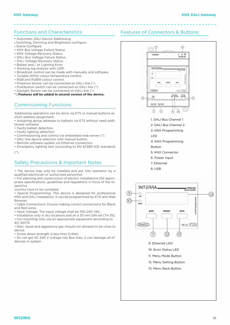
Addressing operations can be done via ETS or manual buttons asshort address assignment.• Assigning group adresses to ballasts via ETS without need addi-tionals software.• Faulty ballast detection.• Faulty lighting detection.• Commissioning and control via embedded web server (*).• DALI line device selection with manual button.• Remote software update via Ethernet connection.• Emergency lighting test (according to EN 62386-202 standard)
(*).
Functions and Characteristics Features of Connectors & Buttons• Automatic DALI Device Addressing• Switching, Dimming and Brightness configure.• Scene Configure• KNX Bus Voltage Failure Status.• KNX Voltage Recovery Status.• DALI Bus Voltage Failure Status.• DALI Voltage Recovery Status.• Ballast and / or Lighting Error.• Working log analysis with UDP.• Broadcast control can be made with manually and software.• Tunable White colour temperature control.• RGB and RGBW colour control.• Presence Sensor can be connected on DALI line (*).• Pushbutton switch can be connected on DALI line (*).• Daylight Sensor can be connected on DALI line (*).* : Features will be added in second version of the device.
Safety Precautions & Important Notes
• The device may only be installed and put into operation by a qualified electrician or authorized personnel.• For planning and construction of electric installations the appro-priate specifications, guidelines and regulations in force of the re-spectivecountry have to be complied.• Special Programming: This device is designed for professional KNX and DALI installation. It can be programmed by ETS and WebBrowser.• Cable Connections: Ensure making correct connections for Black and Red wires.• Input Voltage: The input voltage shall be 100-240 VAC.• Installation only in dry locations and on a 35 mm DIN rail (TH 35).• For mounting only use an appropriate equipment according toIEC 60715.• Rain, liquid and aggressive gas should not allowed to be close todevice.• Screw down strength is less than 0.4Nm.• Do net get AC 240 V voltage into Bus lines, it can damage all ofdevices in system.
1. DALI Bus Channel 1
2. DALI Bus Channel 2
3. KNX Programming
LED
4. KNX Programming
Button
5. KNX Connector
6. Power Input
7. Ethernet
8. USB
9. Ethernet LED
10. Error Status LED
11. Menu Mode Button
12. Menu Setting Button
13. Menu Back Button
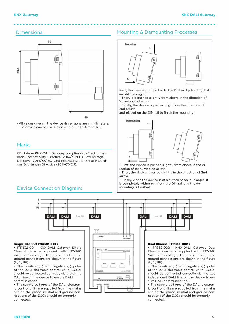
53
Dimensions
Marks
Device Connection Diagram:
Mounting & Demounting Processes
First, the device is contacted to the DIN rail by holding it at an oblique angle.• Then, it is pushed slightly from above in the direction of 1st numbered arrow.• Finally, the device is pushed slightly in the direction of 2nd arrowand placed on the DIN rail to finish the mounting.
• First, the device is pushed slightly from above in the di-rection of 1st numbered arrow.• Then, the device is pulled slightly in the direction of 2nd arrow.• Finally, when the device is at a sufficient oblique angle, it is completely withdrawn from the DIN rail and the de-mounting is finished.
• All values given in the device dimensions are in millimeters.• The device can be used in an area of up to 4 modules.
CE : Interra KNX-DALI Gateway complies with Electromag-netic Compatibility Directive (2014/30/EU), Low Voltage Directive (2014/35/ EU) and Restricting the Use of Hazard-ous Substances Directive (2011/65/EU).
Single Channel ITR832-001 :• ITR832-001 - KNX-DALI Gateway Single Channel devic is supplied with 100-240 VAC mains voltage. The phase, neutral and ground connections are shown in the figure (L, N, PE).• The positive (+) and negative (-) poles of the DALI electronic control units (ECGs) should be connected correctly via the single DALI line on the device to ensure DALIcommunication.• The supply voltages of the DALI electron-ic control units are supplied from the mains and so the phase, neutral and ground con-nections of the ECGs should be properlyconnected.
Dual Channel ITR832-002 :• ITR832-002 - KNX-DALI Gateway Dual Channel device is supplied with 100-240 VAC mains voltage. The phase, neutral and ground connections are shown in the figure (L, N, PE).• The positive (+) and negative (-) poles of the DALI electronic control units (ECGs) should be connected correctly via the two independent DALI line on the device to en-sure DALI communication.• The supply voltages of the DALI electron-ic control units are supplied from the mains and so the phase, neutral and ground con-nections of the ECGs should be properlyconnected.
KNX DALI GatewayKNX Gateway
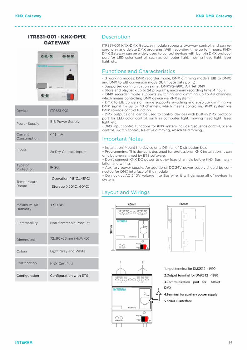
54
Device
Power Supply
CurrentConsumption
Inputs
Type ofProtection
Certification
Temperature Range
Maximum Air Humidity
Dimensions
Colour
ITR831-001
EIB Power Supply
< 15 mA
2x Dry Contact Inputs
Non-flammable Product
72x90x66mm (HxWxD)
KNX Certified
Light Grey and White
ITR831-001 - KNX-DMX GATEWAY
Flammability
IP 20
Configuration Configuration with ETS
< 90 RH
Operation (-5°C...45°C)
Storage (-20°C...60°C)
Description
Important Notes
ITR831-001 KNX-DMX Gateway module supports two-way control, and can re-cord, play and delete DMX programs. With recording time up to 4 hours, KNX-DMX Gateway can be widely used to control devices with built-in DMX protocol port for LED color control, such as computer light, moving head light, laser light, etc.
• Installation: Mount the device on a DIN rail of Distribution box.• Programming: This device is designed for professional KNX installation. It can only be programmed by ETS software.• Don’t connect KNX DC power to other load channels before KNX Bus instal-lation and wiring.• Auxiliary power supply: An additional DC 24V power supply should be con-nected for DMX interface of the module.• Do not get AC 240V voltage into Bus wire, it will damage all of devices in system.
Functions and Characteristics• 3 working modes: DMX recorder mode, DMX dimming mode ( EIB to DMX) and DMX to EIB conversion mode (1bit, 1byte data point)• Supported communication signal: DMX512-1990, ArtNet DMX• Store and playback up to 24 programs, maximum recording time: 4 hours• DMX recorder mode supports switching and dimming up to 48 channels, which means controlling DMX device via KNX system.• DMX to EIB conversion mode supports switching and absolute dimming via DMX signal for up to 48 channels, which means controlling KNX system via DMX storage control function.• DMX output signal can be used to control devices with built-in DMX protocol port for LED color control, such as computer light, moving head light, laser light, etc.• DMX input control functions for KNX system include: Sequence control, Scene control, Switch control, Relative dimming, Absolute dimming.
Layout and Wirings
KNX DMX GatewayKNX Gateway
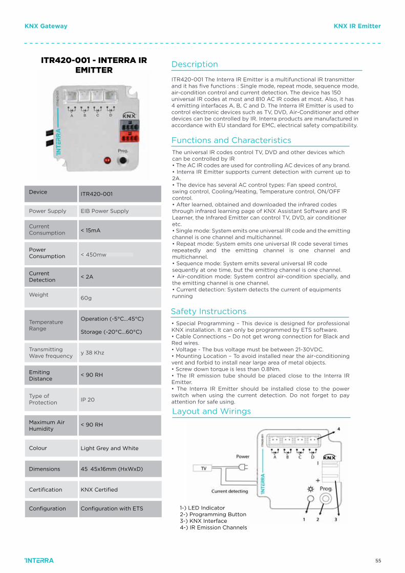
55
KNX IR EmitterKNX Gateway
Power Supply
CurrentConsumption
PowerConsumption
Weight
Transmitting Wave frequency
TemperatureRange
Type ofProtection
Colour
ITR420-001
EIB Power Supply
< 15mA
< 450mw
60g
y 38 Khz
Operation (-5°C...45°C)
Storage (-20°C...60°C)
IP 20
Device
ITR420-001 - INTERRA IR EMITTER
CurrentDetection
< 2A
EmitingDistance
< 90 RH
< 90 RHMaximum AirHumidity
Colour
Dimensions
Certification
Configuration
Light Grey and White
45İ45x16mm (HxWxD)
KNX Certified
Configuration with ETS
Description
ITR420-001 The Interra IR Emitter is a multifunctional IR transmitterand it has five functions : Single mode, repeat mode, sequence mode,air-condition control and current detection. The device has 150universal IR codes at most and 810 AC IR codes at most. Also, it has4 emitting interfaces A, B, C and D. The Interra IR Emitter is used tocontrol electronic devices such as TV, DVD, Air-Conditioner and otherdevices can be controlled by IR. Interra products are manufactured inaccordance with EU standard for EMC, electrical safety compatibility.
Functions and Characteristics
Safety Instructions
The universal IR codes control TV, DVD and other devices whichcan be controlled by IR• The AC IR codes are used for controlling AC devices of any brand.• Interra IR Emitter supports current detection with current up to 2A.• The device has several AC control types: Fan speed control,swing control, Cooling/Heating, Temperature control, ON/OFFcontrol.• After learned, obtained and downloaded the infrared codesthrough infrared learning page of KNX Assistant Software and IRLearner, the Infrared Emitter can control TV, DVD, air conditioneretc.• Single mode: System emits one universal IR code and the emitting channel is one channel and multichannel.• Repeat mode: System emits one universal IR code several timesrepeatedly and the emitting channel is one channel and multichannel.• Sequence mode: System emits several universal IR codesequently at one time, but the emitting channel is one channel.• Air-condition mode: System control air-condition specially, and the emitting channel is one channel.• Current detection: System detects the current of equipmentsrunning
• Special Programming – This device is designed for professional KNX installation. It can only be programmed by ETS software.• Cable Connections – Do not get wrong connection for Black and Red wires.• Voltage - The bus voltage must be between 21-30VDC.• Mounting Location – To avoid installed near the air-conditioning vent and forbid to install near large area of metal objects.• Screw down torque is less than 0.8Nm.• The IR emission tube should be placed close to the Interra IR Emitter.• The Interra IR Emitter should be installed close to the power switch when using the current detection. Do not forget to pay attention for safe using.
Layout and Wirings
1-) LED Indicator2-) Programming Button3-) KNX Interface4-) IR Emission Channels
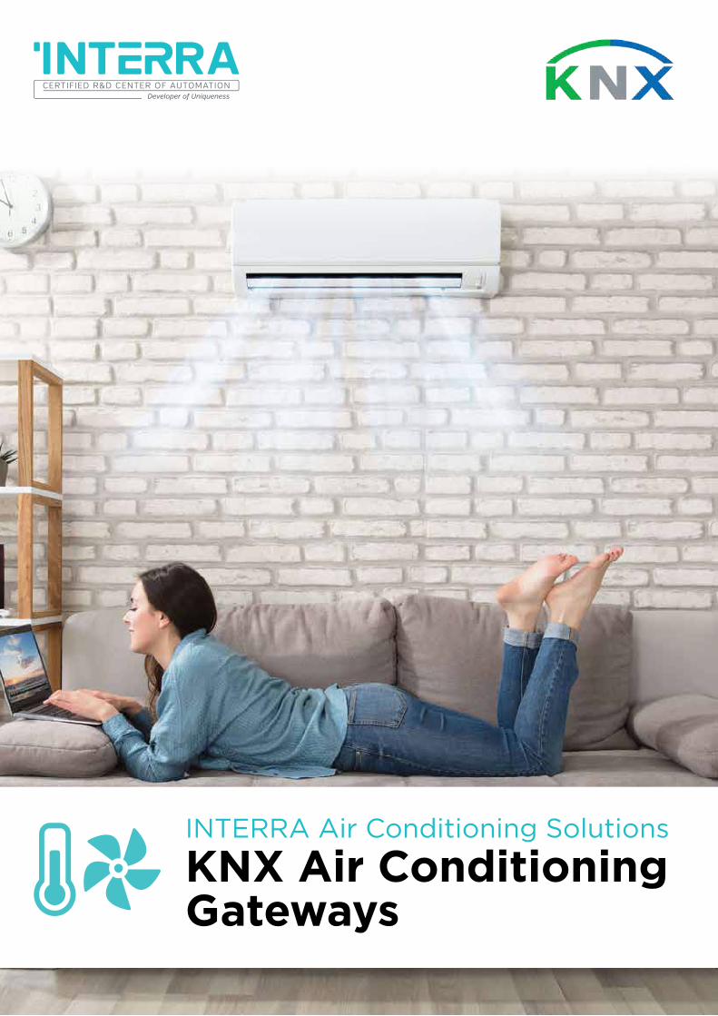
56
INTERRA Air Conditioning Solutions
KNX Air ConditioningGateways
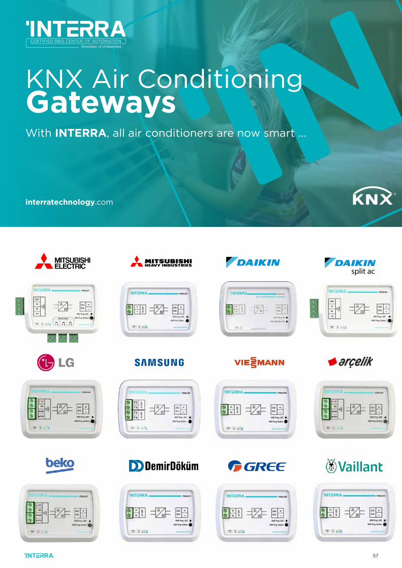
57
split ac
KNX Air ConditioningGatewaysWith INTERRA, all air conditioners are now smart ...
interratechnology.com
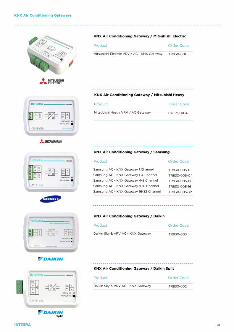
58
Order CodeProduct
ITR830-001Mitsubishi Electric VRV / AC - KNX Gateway
KNX Air Conditioning Gateway / Mitsubishi Electric
KNX Air Conditioning Gateways
Order CodeProduct
ITR830-005-01
ITR830-005-04
ITR830-005-08
ITR830-005-16
ITR830-005-32
Samsung AC - KNX Gateway 1 Channel
Samsung AC - KNX Gateway 1-4 Channel
Samsung AC - KNX Gateway 4-8 Channel
Samsung AC - KNX Gateway 8-16 Channel
Samsung AC - KNX Gateway 16-32 Channel
KNX Air Conditioning Gateway / Samsung
Order CodeProduct
ITR830-004Mitsubishi Heavy VRV / AC Gateway
KNX Air Conditioning Gateway / Mitsubishi Heavy
Order Code
Order Code
Product
Product
ITR830-003
ITR830-002
Daikin Sky & VRV AC - KNX Gateway
Daikin Sky & VRV AC - KNX Gateway
KNX Air Conditioning Gateway / Daikin
KNX Air Conditioning Gateway / Daikin Split
Split
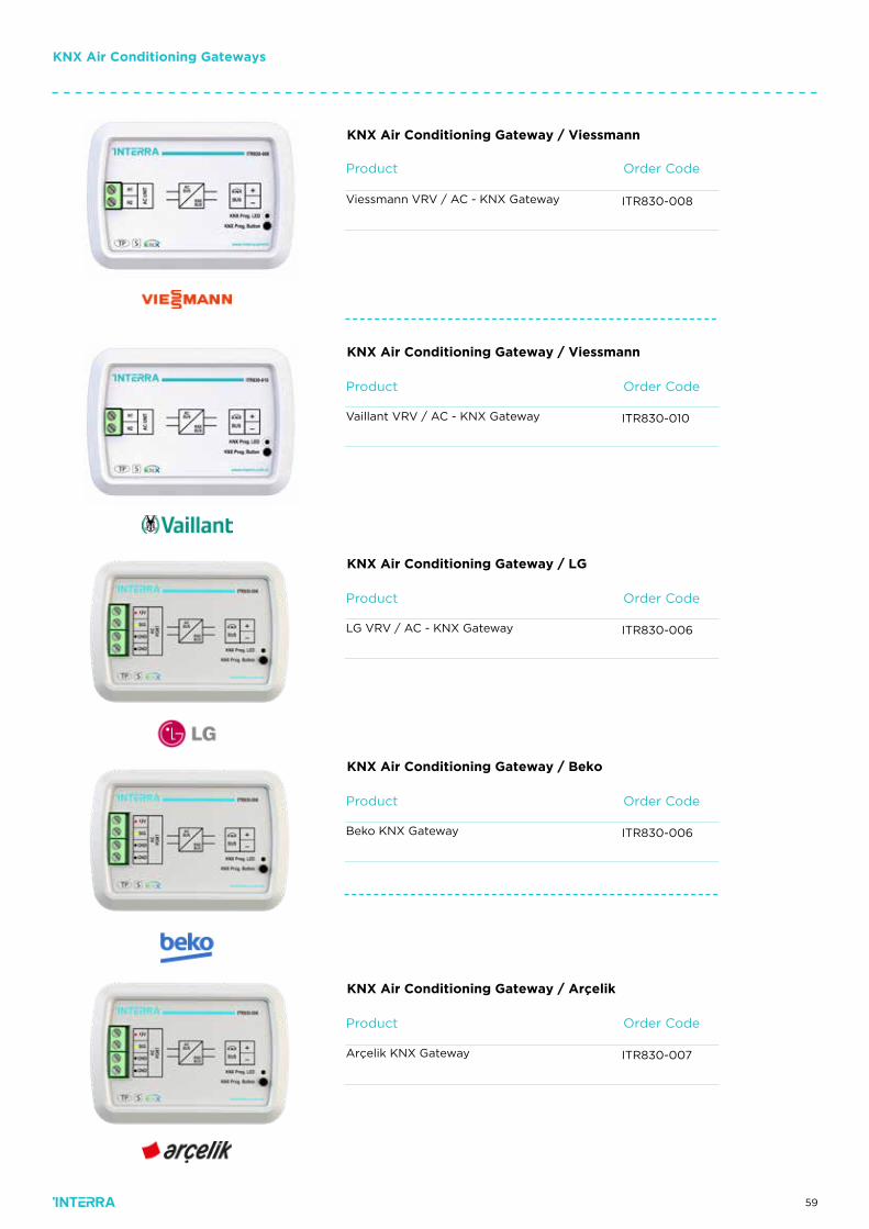
59
KNX Air Conditioning Gateways
Order CodeProduct
ITR830-008Viessmann VRV / AC - KNX Gateway
KNX Air Conditioning Gateway / Viessmann
Order CodeProduct
ITR830-010Vaillant VRV / AC - KNX Gateway
KNX Air Conditioning Gateway / Viessmann
Order CodeProduct
ITR830-006LG VRV / AC - KNX Gateway
KNX Air Conditioning Gateway / LG
Order CodeProduct
ITR830-007Arçelik KNX Gateway
KNX Air Conditioning Gateway / Arçelik
Order CodeProduct
ITR830-006Beko KNX Gateway
KNX Air Conditioning Gateway / Beko

60
Order Code
Order Code
Product
Product
ITR830-011
ITR830-009
Demir Döküm & VRV AC - KNX Gateway
Gree & VRV AC - KNX Gateway
KNX Air Conditioning Gateway / Demir Döküm
KNX Air Conditioning Gateway / Gree
KNX Air Conditioning Gateways
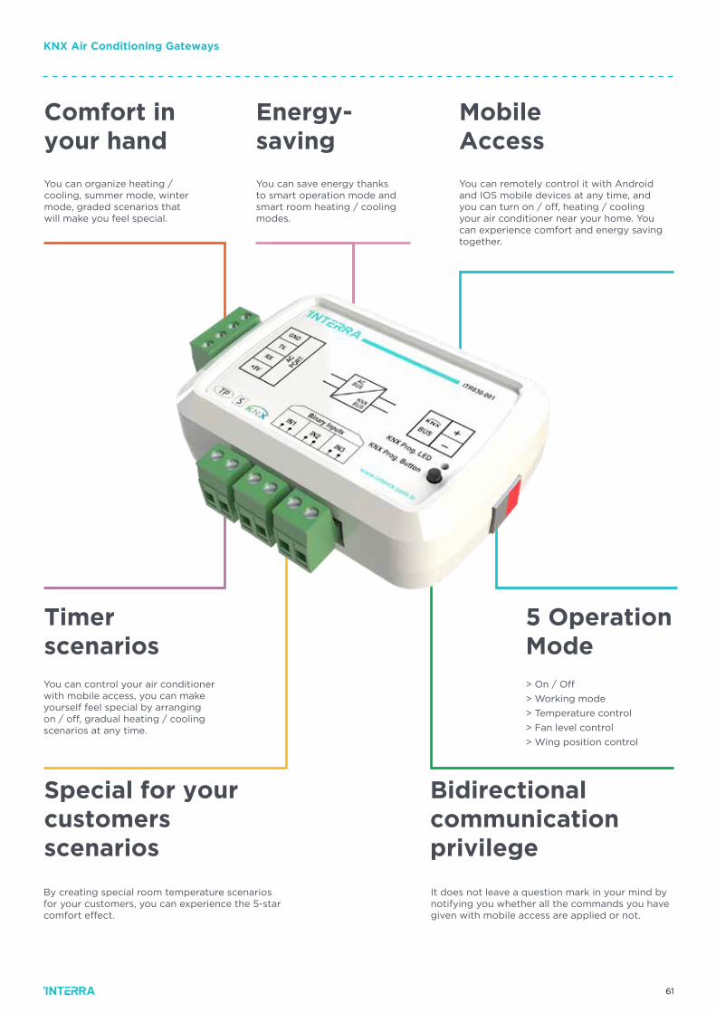
61
KNX Air Conditioning Gateways
You can organize heating / cooling, summer mode, winter mode, graded scenarios that will make you feel special.
You can save energy thanks to smart operation mode and smart room heating / cooling modes.
You can remotely control it with Android and IOS mobile devices at any time, and you can turn on / off, heating / cooling your air conditioner near your home. You can experience comfort and energy saving together.
You can control your air conditioner with mobile access, you can make yourself feel special by arranging on / off, gradual heating / cooling scenarios at any time.
By creating special room temperature scenarios for your customers, you can experience the 5-star comfort effect.
> On / Off
> Working mode
> Temperature control
> Fan level control
> Wing position control
It does not leave a question mark in your mind by notifying you whether all the commands you have given with mobile access are applied or not.
Comfort in your hand
Timerscenarios
Special for your customersscenarios
Bidirectional communication privilege
5 OperationMode
Energy-saving
Mobile Access
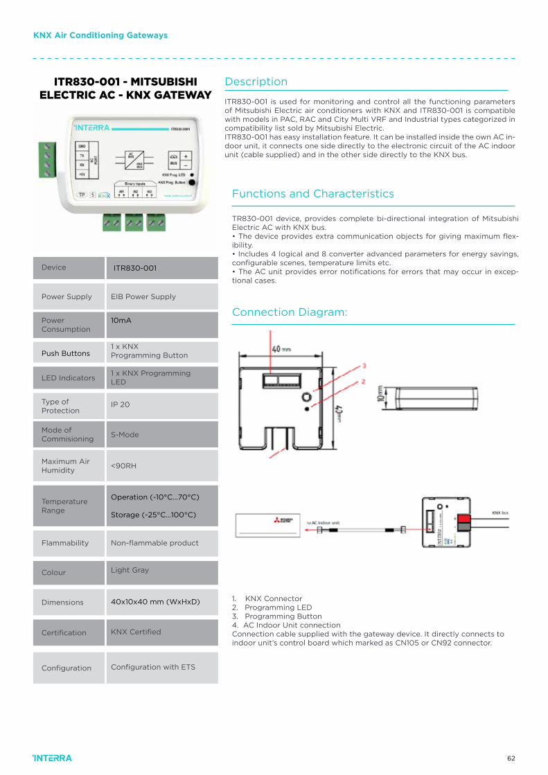
62
ITR830-001 - MITSUBISHI ELECTRIC AC - KNX GATEWAY
Device
Power Supply
Power Consumption
Push Buttons
LED Indicators
Type of Protection
Mode ofCommisioning
Maximum AirHumidity
TemperatureRange
Flammability
Colour
Dimensions
Certification
Configuration
ITR830-001
EIB Power Supply
10mA
1 x KNX Programming Button
1 x KNX Programming LED
IP 20
S-Mode
<90RH
Operation (-10°C…70°C)
Storage (-25°C…100°C)
Non-flammable product
Light Gray
40x10x40 mm (WxHxD)
KNX Certified
Configuration with ETS
Description
ITR830-001 is used for monitoring and control all the functioning parameters of Mitsubishi Electric air conditioners with KNX and ITR830-001 is compatible with models in PAC, RAC and City Multi VRF and Industrial types categorized in compatibility list sold by Mitsubishi Electric.ITR830-001 has easy installation feature. It can be installed inside the own AC in-door unit, it connects one side directly to the electronic circuit of the AC indoor unit (cable supplied) and in the other side directly to the KNX bus.
Functions and Characteristics
Connection Diagram:
TR830-001 device, provides complete bi-directional integration of Mitsubishi Electric AC with KNX bus.• The device provides extra communication objects for giving maximum flex-ibility.• Includes 4 logical and 8 converter advanced parameters for energy savings, configurable scenes, temperature limits etc.• The AC unit provides error notifications for errors that may occur in excep-tional cases.
1. KNX Connector2. Programming LED3. Programming Button4. AC Indoor Unit connectionConnection cable supplied with the gateway device. It directly connects to indoor unit’s control board which marked as CN105 or CN92 connector.
KNX Air Conditioning Gateways
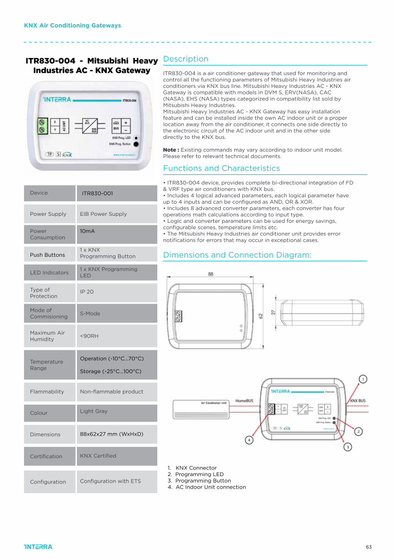
63
KNX Air Conditioning Gateways
ITR830-004 - Mitsubishi Heavy Industries AC - KNX Gateway
Device
Power Supply
Power Consumption
Push Buttons
LED Indicators
Type of Protection
Mode ofCommisioning
Maximum AirHumidity
TemperatureRange
Flammability
Colour
Dimensions
Certification
Configuration
ITR830-001
EIB Power Supply
10mA
1 x KNX Programming Button
1 x KNX Programming LED
IP 20
S-Mode
<90RH
Operation (-10°C…70°C)
Storage (-25°C…100°C)
Non-flammable product
Light Gray
88x62x27 mm (WxHxD)
KNX Certified
Configuration with ETS
Description
ITR830-004 is a air conditioner gateway that used for monitoring andcontrol all the functioning parameters of Mitsubishi Heavy Industries airconditioners via KNX bus line. Mitsubishi Heavy Industries AC - KNXGateway is compatible with models in DVM S, ERV(NASA), CAC(NASA), EHS (NASA) types categorized in compatibility list sold byMitsubishi Heavy Industries.Mitsubishi Heavy Industries AC - KNX Gateway has easy installationfeature and can be installed inside the own AC indoor unit or a properlocation away from the air conditioner, it connects one side directly tothe electronic circuit of the AC indoor unit and in the other sidedirectly to the KNX bus.
Note : Existing commands may vary according to indoor unit model.Please refer to relevant technical documents.
Functions and Characteristics
Dimensions and Connection Diagram:
• ITR830-004 device, provides complete bi-directional integration of FD& VRF type air conditioners with KNX bus.• Includes 4 logical advanced parameters, each logical parameter haveup to 4 inputs and can be configured as AND, OR & XOR.• Includes 8 advanced converter parameters, each converter has fouroperations math calculations according to input type.• Logic and converter parameters can be used for energy savings,configurable scenes, temperature limits etc.• The Mitsubishi Heavy Industries air conditioner unit provides errornotifications for errors that may occur in exceptional cases.
1. KNX Connector2. Programming LED3. Programming Button4. AC Indoor Unit connection
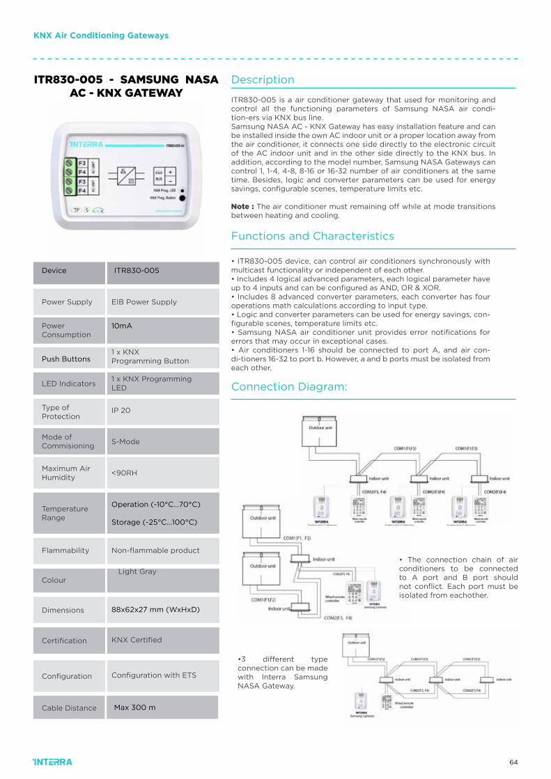
64
Power Supply
Power Consumption
Push Buttons
LED Indicators
Type of Protection
Mode ofCommisioning
Maximum AirHumidity
TemperatureRange
Flammability
Colour
Dimensions
Certification
Configuration
ITR830-005
EIB Power Supply
10mA
1 x KNX Programming Button
1 x KNX Programming LED
IP 20
S-Mode
<90RH
Operation (-10°C…70°C)
Storage (-25°C…100°C)
Non-flammable product
Light Gray
88x62x27 mm (WxHxD)
KNX Certified
Configuration with ETS
Cable Distance Max 300 m
Device
ITR830-005 - SAMSUNG NASA AC - KNX GATEWAY
Description
ITR830-005 is a air conditioner gateway that used for monitoring and control all the functioning parameters of Samsung NASA air condi-tion-ers via KNX bus line.Samsung NASA AC - KNX Gateway has easy installation feature and can be installed inside the own AC indoor unit or a proper location away from the air conditioner, it connects one side directly to the electronic circuit of the AC indoor unit and in the other side directly to the KNX bus. In addition, according to the model number, Samsung NASA Gateways can control 1, 1-4, 4-8, 8-16 or 16-32 number of air conditioners at the same time. Besides, logic and converter parameters can be used for energy savings, configurable scenes, temperature limits etc.
Note : The air conditioner must remaining off while at mode transitions between heating and cooling.
Functions and Characteristics
Connection Diagram:
• ITR830-005 device, can control air conditioners synchronously with multicast functionality or independent of each other.• Includes 4 logical advanced parameters, each logical parameter have up to 4 inputs and can be configured as AND, OR & XOR.• Includes 8 advanced converter parameters, each converter has four operations math calculations according to input type.• Logic and converter parameters can be used for energy savings, con-figurable scenes, temperature limits etc.• Samsung NASA air conditioner unit provides error notifications for errors that may occur in exceptional cases.• Air conditioners 1-16 should be connected to port A, and air con-di-tioners 16-32 to port b. However, a and b ports must be isolated from each other.
• The connection chain of air conditioners to be connected to A port and B port should not conflict. Each port must be isolated from eachother.
•3 different type connection can be made with Interra Samsung NASA Gateway.
KNX Air Conditioning Gateways
65
KNX Air Conditioning Gateways
ITR830-003 - DAIKIN SKY & VRV AC - KNX GATEWAY
Device
Power Supply
Power Consumption
Push Buttons
LED Indicators
Type of Protection
Mode ofCommisioning
Maximum AirHumidity
TemperatureRange
Flammability
Colour
Dimensions
Certification
Configuration
ITR830-003
EIB Power Supply
20mA
1 x KNX Programming Button
1 x KNX Programming LED
IP 20
S-Mode
<90RH
Operation (-10°C…70°C)
Storage (-25°C…100°C)
Non-flammable product
Light Gray
88x62x27 mm (WxHxD)
KNX Certified
Configuration with ETS
Description
ITR830-003 is a air conditioner gateway that used for monitoring and control all the functioning parameters of Daikin Industries air condition-ers via KNX bus line. Daikin Sky & VRV AC - KNX Gateway is compatible with models in Sky & VRV types categorized in compatibil-ity list sold by Daikin Industries.Daikin Sky & VRV AC - KNX Gateway has easy installation feature and can be installed inside the own AC indoor unit or a proper location away from the air conditioner, it connects one side directly to the electronic circuit of the AC indoor unit and in the other side directly to the KNX bus.
Functions and Characteristics
Dimensions and Connection Diagram:
ITR830-003 device, provides complete bi-directional integration of Dai-kin Sky & VRV air conditioners with KNX bus.• Includes 4 logical advanced parameters, each logical parameter have up to 4 inputs and can be configured as AND, OR & XOR.• Includes 8 advanced converter parameters, each converter has four operations math calculations according to input type.• Logic and converter parameters can be used for energy savings, con-figurable scenes, temperature limits etc.• The Daikin air conditioner unit provides error notifications for errors that may occur in exceptional cases.
1. KNX Connector2. Programming LED3. Programming Button4. AC Indoor Unit connection
66
KNX Air Conditioning Gateways
ITR830-003 - DAIKIN SKY & VRV AC - KNX GATEWAY
Power Supply
Power Consumption
Push Buttons
LED Indicators
Type of Protection
Mode ofCommisioning
Maximum AirHumidity
TemperatureRange
Flammability
Colour
Dimensions
Certification
Configuration
ITR830-002
EIB Power Supply
10mA
1 x KNX Programming Button
1 x KNX Programming LED
IP 20
S-Mode
<90RH
Operation (-10°C…70°C)
Storage (-25°C…100°C)
Non-flammable product
Light Gray
88x62x27 mm (WxHxD)
KNX Certified
Configuration with ETS
Device
Description
Functions and Characteristics
Dimensions & Connection Diagram
ITR830-002 is an air conditioner gateway that used for monitoring and control all the functioning parameters of Daikin Industries air conditioners via KNX bus line. Daikin Split AC - KNX Gateway is compatible with models in split types categorized in compatibility list sold by Daikin Industries.Daikin Split AC - KNX Gateway has easy installation feature and can be installed inside the own AC indoor unit or a proper location away from the air condition-er, it connects one side directly to the electronic circuit of the AC indoor unit and in the other side directly to the KNX bus.
• ITR830-002 device, provides complete bi-directional integration of Daikin Split air conditioners with KNX bus.• Includes 4 logical advanced parameters, each logical parameter have up to 4 inputs and can be configured as AND, OR & XOR.• Includes 8 advanced converter parameters, each converter has four opera-tions math calculations according to input type.• Logic and converter parameters can be used for energy savings, configurable scenes, temperature limits etc.• The Daikin air conditioner unit provides error notifications for errors that may occur in exceptional cases.
67
KNX Air Conditioning Gateways
ITR830-006 - LG AC - KNX GATEWAY
Device
Power Supply
Power Consumption
Push Buttons
LED Indicators
Type of Protection
Mode ofCommisioning
Maximum AirHumidity
TemperatureRange
Flammability
Colour
Dimensions
Certification
Configuration
ITR830-006
EIB Power Supply
10mA
1 x KNX Programming Button
1 x KNX Programming LED
IP 20
S-Mode
<90RH
Operation (0°C…40°C)
Storage (-10°C…70°C)
Non-flammable product
Light Gray
88x62x27 mm (WxHxD)
KNX Certified
Configuration with ETS
Description
Functions and Characteristics
ITR830-006 is a air conditioner gateway that used for monitoring and control all the functioning parameters of LG air conditioners via KNX bus line. LG AC - KNX Gateway is compatible with models in single, multi, multi-f, multi-f max and VRF types categorized in compatibility list sold by LG.LG AC - KNX Gateway has easy installation feature and can be in-stalled inside the own AC indoor unit or a proper location away from the air conditioner, it connects one side directly to the electronic circuit of the AC indoor unit and in the other side directly to the KNX bus.
ITR830-006 device, provides complete bi-directional integration of LG air con-ditioners with KNX bus.• Includes 4 logical advanced parameters, each logical parameter have up to 4 inputs and can be configured as AND, OR & XOR.• Includes 8 advanced converter parameters, each converter has four opera-tions math calculations according to input type.• Logic and converter parameters can be used for energy savings, configurable scenes, temperature limits etc.• The LG AC - KNX gateway provides error notifications for errors that may occur in exceptional cases.
68
KNX Air Conditioning Gateways
ITR830-007 - ARCELIK AC - KNX GATEWAY
Device
Power Supply
Power Consumption
Push Buttons
LED Indicators
Type of Protection
Mode ofCommisioning
Maximum AirHumidity
TemperatureRange
Flammability
Colour
Dimensions
Certification
Configuration
ITR830-007
EIB Power Supply
10mA
1 x KNX Programming Button
1 x KNX Programming LED
IP 20
S-Mode
<90RH
Operation (0°C…40°C)
Storage (-10°C…70°C)
Non-flammable product
Light Gray
88x62x27 mm (WxHxD)
KNX Certified
Configuration with ETS
Description
Functions and Characteristics
ITR830-007 is a air conditioner gateway that used for monitoring and control all the functioning parameters of Arcelik air conditioners via KNX bus line. Arce-lik AC - KNX Gateway is compatible with models in several types categorized in compatibility list by Arcelik.Arcelik AC - KNX Gateway has easy installation feature and can be installed in-side the own AC indoor unit or a proper location away from the air conditioner, it connects one side directly to the electronic circuit of the AC indoor unit and in the other side directly to the KNX bus.
• ITR830-007 device, provides complete bi-directional integration of Arcelik air conditioners with KNX bus.• Includes 4 logical advanced parameters, each logical parameter have up to 4 inputs and can be configured as AND, OR & XOR.• Includes 8 advanced converter parameters, each converter has four opera-tions math calculations according to input type.• Logic and converter parameters can be used for energy savings, configurable scenes, temperature limits etc.• The Arcelik AC - KNX gateway provides error notifications for errors that may occur in exceptional cases.
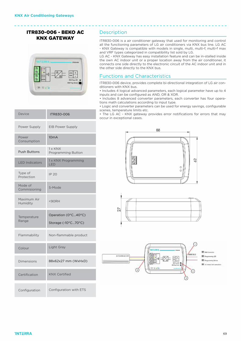
69
KNX Air Conditioning Gateways
ITR830-006 - BEKO ACKNX GATEWAY
Device
Power Supply
Power Consumption
Push Buttons
LED Indicators
Type of Protection
Mode ofCommisioning
Maximum AirHumidity
TemperatureRange
Flammability
Colour
Dimensions
Certification
Configuration
ITR830-006
EIB Power Supply
10mA
1 x KNX Programming Button
1 x KNX Programming LED
IP 20
S-Mode
<90RH
Operation (0°C…40°C)
Storage (-10°C…70°C)
Non-flammable product
Light Gray
88x62x27 mm (WxHxD)
KNX Certified
Configuration with ETS
Description
Functions and Characteristics
ITR830-006 is a air conditioner gateway that used for monitoring and control all the functioning parameters of LG air conditioners via KNX bus line. LG AC - KNX Gateway is compatible with models in single, multi, multi-f, multi-f max and VRF types categorized in compatibility list sold by LG.LG AC - KNX Gateway has easy installation feature and can be in-stalled inside the own AC indoor unit or a proper location away from the air conditioner, it connects one side directly to the electronic circuit of the AC indoor unit and in the other side directly to the KNX bus.
ITR830-006 device, provides complete bi-directional integration of LG air con-ditioners with KNX bus.• Includes 4 logical advanced parameters, each logical parameter have up to 4 inputs and can be configured as AND, OR & XOR.• Includes 8 advanced converter parameters, each converter has four opera-tions math calculations according to input type.• Logic and converter parameters can be used for energy savings, configurable scenes, temperature limits etc.• The LG AC - KNX gateway provides error notifications for errors that may occur in exceptional cases.
701
KNX/DALI SYSTEMSensors/Detectors
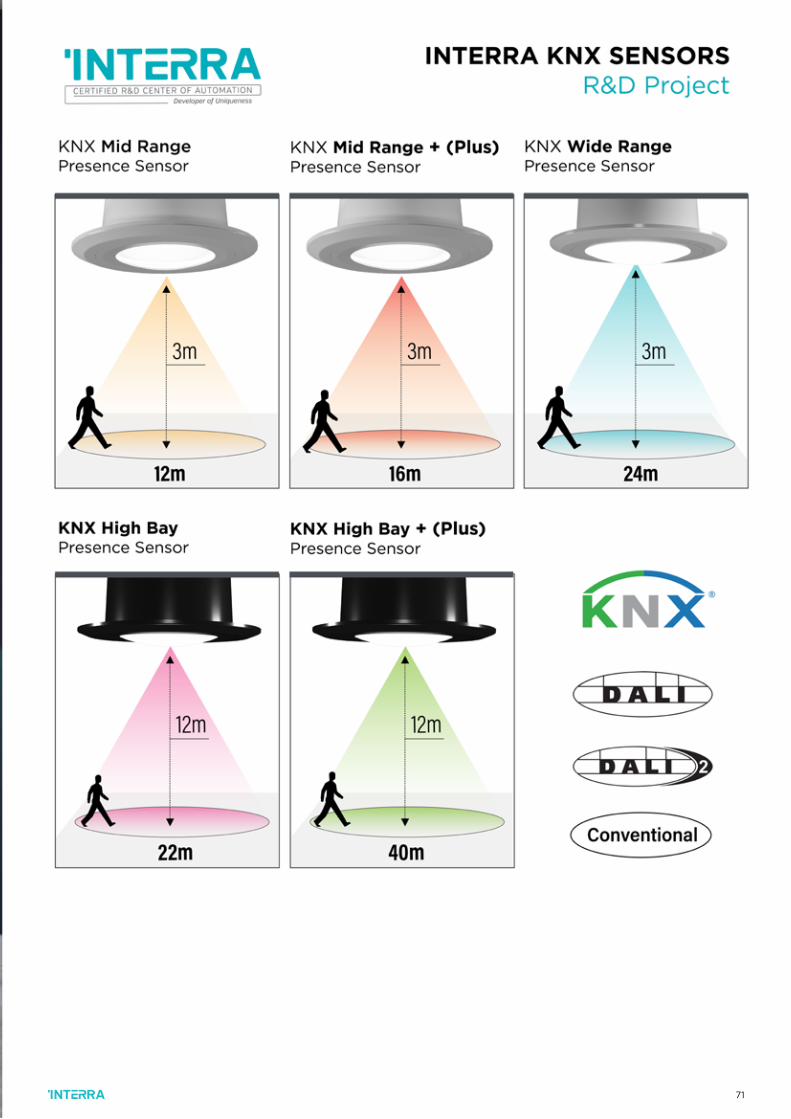
711
KNX/DALI SYSTEMSensors/Detectors
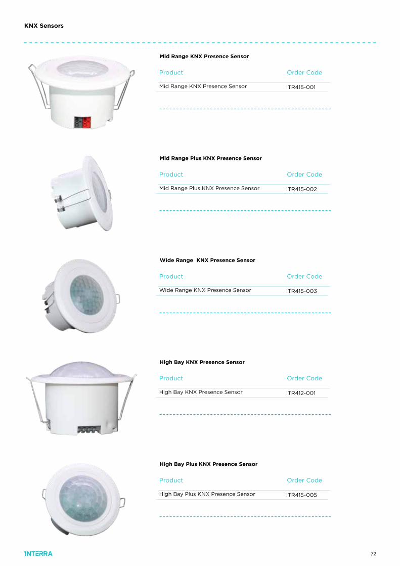
72
Order CodeProduct
ITR415-001Mid Range KNX Presence Sensor
Mid Range KNX Presence Sensor
KNX Sensors
Order CodeProduct
ITR415-002Mid Range Plus KNX Presence Sensor
Mid Range Plus KNX Presence Sensor
Order CodeProduct
ITR415-003Wide Range KNX Presence Sensor
Wide Range KNX Presence Sensor
Order CodeProduct
ITR412-001High Bay KNX Presence Sensor
High Bay KNX Presence Sensor
Order CodeProduct
ITR415-005High Bay Plus KNX Presence Sensor
High Bay Plus KNX Presence Sensor
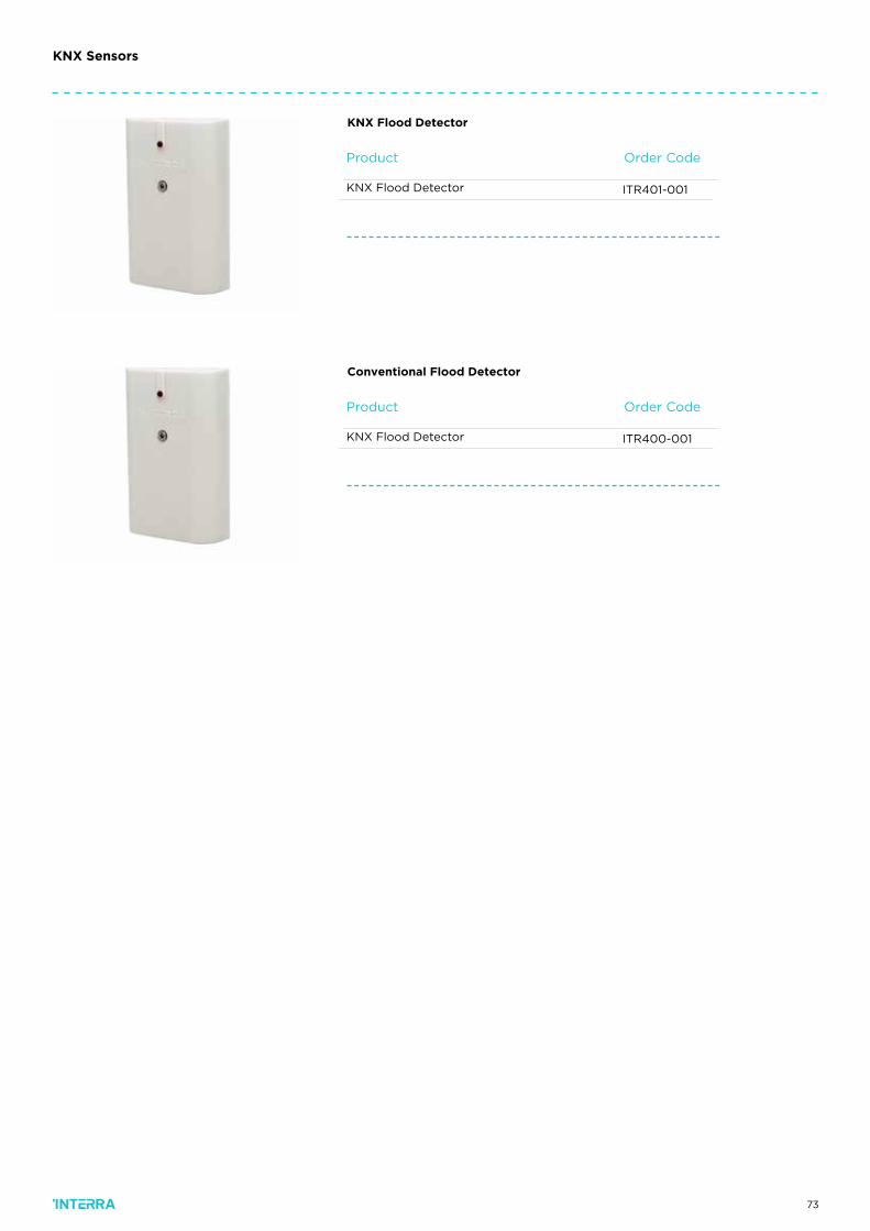
73
KNX Sensors
Order CodeProduct
ITR401-001KNX Flood Detector
KNX Flood Detector
Order CodeProduct
ITR400-001KNX Flood Detector
Conventional Flood Detector
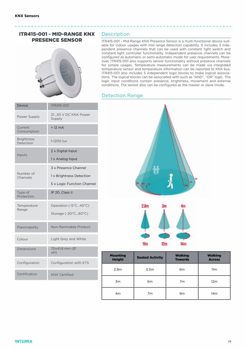
74
Power Supply
CurrentConsumption
BrightnessDetection
Inputs
Certification
Number of Channels
Type ofProtection
Flammability
Colour
ITR415-001
21...30 V DC KNX Power Supply
< 12 mA
1-1200 lux
Operation (-5°C...45°C)
Storage (-20°C...60°C)
Non-flammable Product
KNX Certified
Light Grey and White
ITR415-001 - MID-RANGE KNX PRESENCE SENSOR
Description
Detection Range
ITR415-001 - Mid-Range KNX Presence Sensor is a multi-functional device suit-able for indoor usages with mid range detection capability. It includes 3 inde-pendent presence channels that can be used with constant light switch and constant light controller functionality. Independent presence channels can be configured as automatic or semi-automatic mode for user requirements. More-over, ITR415-001 also supports sensor functionality without presence channels for simple usages. Temperature measurements can be made via integrated temperature sensor and temperature information can be reported to KNX bus. ITR415-001 also includes 5 independent logic blocks to make logical associa-tions. The logical blocks can be associated with such as “AND”, “OR” logic. The logic input conditions contain presence, brightness, movement and external conditions. The sensor also can be configured as the master or slave mode.
TemperatureRange
2 x Digital Input
1 x Analog Input
3 x Presence Channel
1 x Brightness Detection
5 x Logic Function Channel
Configuration Configuration with ETS
IP 20, Class II
Device
MountingHeight
Seated ActivityWalkingTowards
WalkingAcross
2.8m 5.5m 6m 11m
3m 6m 7m 12m
4m 7m 8m 14m
Dimensions 70x41,8 mm (Ø xH)
KNX Sensors
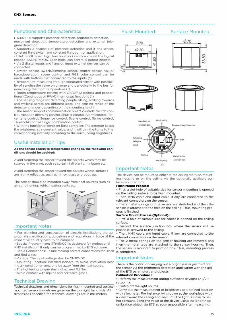
75
Useful Installation Tips
Important Notes
Important Notes
Important Notes
Technical Drawing
Functions and Characteristics Flush Mounted: Surface Mounted
As the sensor reacts to temperature changes, the following con-ditions should be avoided:
Avoid targeting the sensor toward the objects which may beswayed in the wind, such as curtain, tall plants, miniature etc.
Avoid targeting the sensor toward the objects whose surfacesare highly reflective, such as mirror, glass and pool, etc.
The sensor should be mounted away from heat sources such asair conditioning, lights, heating vents etc.
• For planning and construction of electric installations the ap-propriate specifications, guidelines and regulations in force of the respective country have to be complied.• Special Programming: ITR415-001 is designed for professionalKNX installation. It only can be programmed by ETS software.• Cable Connections: Ensure making correct connections for Blackand Red wires.• Voltage: The input voltage shall be 21-30VDC.• Mounting Location: Installed indoors, to avoid installation near the air-conditioner vent, and be away from the heat source.• The tightening torque shall not exceed 0.2Nm.• Avoid contact with liquids and corrosive gases.
The device can be mounted either in the ceiling via flush mount-ing housing or on the ceiling via the optionally available sur-face-mounted box.Flush Mount Process:• First, a slot hole of suitable size for sensor mounting is opened on the ceiling surface to be flush mounted.• Then, KNX cable and input cable, if any, are connected to the relevant connectors on the sensor.• The 2 metal springs on the sensor are stretched and then the sensor is attached to the hole on the ceiling. Thus, mounting pro-cess is finished.Surface Mount Process (Optional) :• First, a hole of suitable size for cables is opened on the ceiling surface.• Second, the surface junction box where the sensor will be placed is screwed to the ceiling.• Then, KNX cable and input cable, if any, are connected to the relevant connectors on the sensor.• The 2 metal springs on the sensor housing are removed and then the metal tabs are attached to the sensor housing. Then, the sensor is mounted to junction box. Thus, mounting process is completed.
ITR415-001 supports presence detection, brightness detection,movement detection, temperature detection and external tele-gram detection.• Supports 3 channels of presence detection and it has sensor, constant light switch and constant light control application.• ITR415-001 have 5 logic function blocks and can be set the logicalrelation AND/OR/XOR. Each block can control 5 output objects.• Via 2 digital inputs and 1 analog input external devices can beconnected.• Switch sensor, switch/dimming sensor, shutter sensor, value/forcedoperation, scene control and RGB color control can be made with buttons that connected to the inputs (*)• Temperature measuring through integrated sensor with possibil-ity of sending the value on change and periodically to the bus for monitoring the room temperature (*)• Room temperature control with On/Off (2-points) and propor-tional (Continuous or PWM) thermostat functions (*)• The sensing range for detecting people sitting, walking towards and walking across are different sizes. The sensing range of the detector changes depending on the mounting height.• The sensor supports communication object controls: Switch con-trol, Absolute dimming control, Shutter control, Alarm control, Per-centage control, Sequence control, Scene control, String control, Threshold control, Logic combination control.• With the function of constant light controller: The detector keeps the brightness at a constant value, and it will dim the lights to thecorresponding intensity according to the surrounding brightness.
Technical drawings and dimensions for flush mounted and surfacemounted sensor models are given on the top right hand side. All dimensions specified for technical drawings are in millimeters.
There is the option of carrying out a brightness adjustment for the sensor via the brightness detection application with the aid of the ETS parameters and objects.Calibration Procedure :• Perform the measurement during sufficient daylight (> 1/2 * setpoint).• Switch off the light source.• Carry out the measurement of brightness at a defined location with a luxmeter. For instance, lying down at the workplace with a view toward the ceiling and wait until the light is close to be-ing constant. Send the value to the device using the brightness calibration object via ETS as soon as possible after measuring.
KNX Sensors
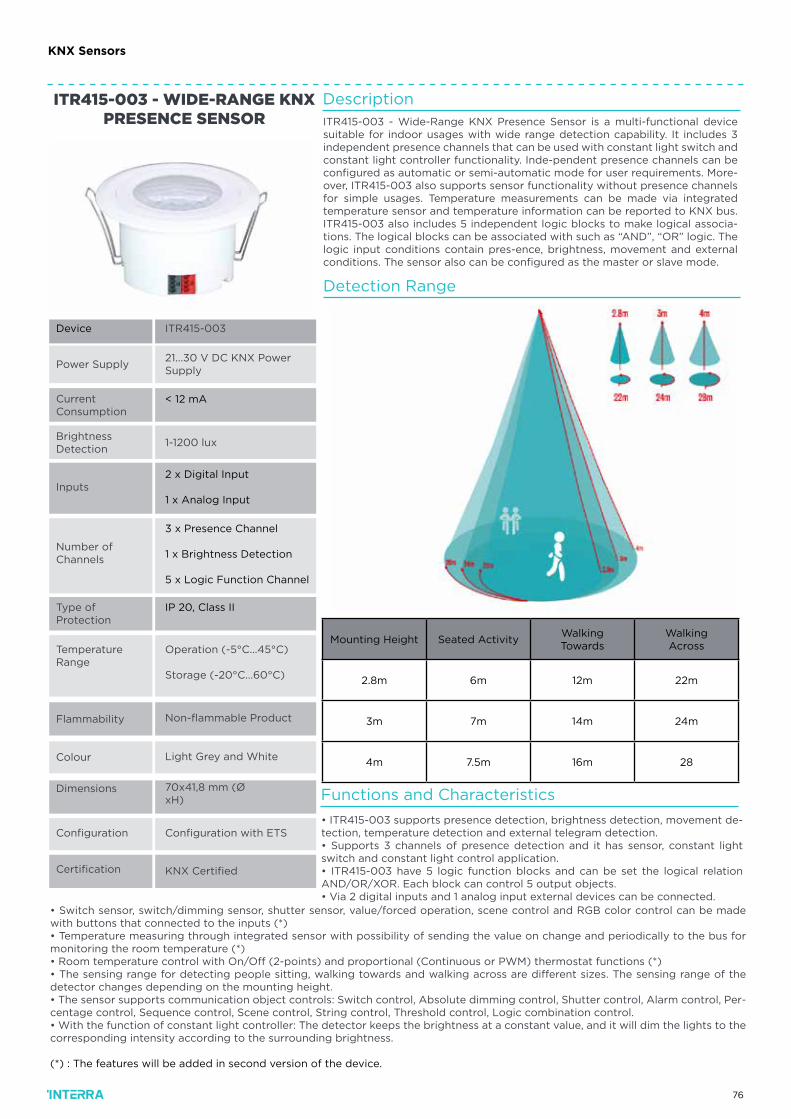
76
Power Supply
CurrentConsumption
BrightnessDetection
Inputs
Certification
Number of Channels
Type ofProtection
Flammability
Colour
ITR415-003
21...30 V DC KNX Power Supply
< 12 mA
1-1200 lux
Operation (-5°C...45°C)
Storage (-20°C...60°C)
Non-flammable Product
KNX Certified
Light Grey and White
ITR415-003 - WIDE-RANGE KNX PRESENCE SENSOR
TemperatureRange
2 x Digital Input
1 x Analog Input
3 x Presence Channel
1 x Brightness Detection
5 x Logic Function Channel
Configuration Configuration with ETS
IP 20, Class II
Device
Dimensions 70x41,8 mm (Ø xH)
Description
Functions and Characteristics
Detection Range
ITR415-003 - Wide-Range KNX Presence Sensor is a multi-functional device suitable for indoor usages with wide range detection capability. It includes 3 independent presence channels that can be used with constant light switch and constant light controller functionality. Inde-pendent presence channels can be configured as automatic or semi-automatic mode for user requirements. More-over, ITR415-003 also supports sensor functionality without presence channels for simple usages. Temperature measurements can be made via integrated temperature sensor and temperature information can be reported to KNX bus. ITR415-003 also includes 5 independent logic blocks to make logical associa-tions. The logical blocks can be associated with such as “AND”, “OR” logic. The logic input conditions contain pres-ence, brightness, movement and external conditions. The sensor also can be configured as the master or slave mode.
• ITR415-003 supports presence detection, brightness detection, movement de-tection, temperature detection and external telegram detection.• Supports 3 channels of presence detection and it has sensor, constant light switch and constant light control application.• ITR415-003 have 5 logic function blocks and can be set the logical relation AND/OR/XOR. Each block can control 5 output objects.• Via 2 digital inputs and 1 analog input external devices can be connected.
• Switch sensor, switch/dimming sensor, shutter sensor, value/forced operation, scene control and RGB color control can be made with buttons that connected to the inputs (*)• Temperature measuring through integrated sensor with possibility of sending the value on change and periodically to the bus for monitoring the room temperature (*)• Room temperature control with On/Off (2-points) and proportional (Continuous or PWM) thermostat functions (*)• The sensing range for detecting people sitting, walking towards and walking across are different sizes. The sensing range of the detector changes depending on the mounting height.• The sensor supports communication object controls: Switch control, Absolute dimming control, Shutter control, Alarm control, Per-centage control, Sequence control, Scene control, String control, Threshold control, Logic combination control.• With the function of constant light controller: The detector keeps the brightness at a constant value, and it will dim the lights to the corresponding intensity according to the surrounding brightness.
(*) : The features will be added in second version of the device.
Mounting Height Seated ActivityWalkingTowards
WalkingAcross
2.8m 6m 12m 22m
3m 7m 14m 24m
4m 7.5m 16m 28
KNX Sensors
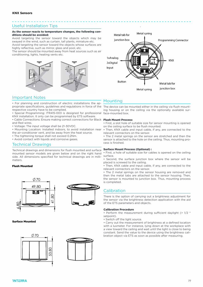
77
Useful Installation Tips
Important Notes
Calibration
Mounting
Technical Drawings
As the sensor reacts to temperature changes, the following con-ditions should be avoided:Avoid targeting the sensor toward the objects which may be swayed in the wind, such as curtain, tall plants, miniature etc.Avoid targeting the sensor toward the objects whose surfaces are highly reflective, such as mirror, glass and pool, etc.The sensor should be mounted away from heat sources such as air conditioning, lights, heating vents etc.
• For planning and construction of electric installations the ap-propriate specifications, guidelines and regulations in force of the respective country have to be complied.• Special Programming: ITR415-003 is designed for professional KNX installation. It only can be programmed by ETS software.• Cable Connections: Ensure making correct connections for Black and Red wires.• Voltage: The input voltage shall be 21-30VDC.• Mounting Location: Installed indoors, to avoid installation near the air-conditioner vent, and be away from the heat source.• The tightening torque shall not exceed 0.2Nm.• Avoid contact with liquids and corrosive gases.
There is the option of carrying out a brightness adjustment for the sensor via the brightness detection application with the aid of the ETS parameters and objects.
Calibration Procedure• Perform the measurement during sufficient daylight (> 1/2 * setpoint).• Switch off the light source.• Carry out the measurement of brightness at a defined location with a luxmeter. For instance, lying down at the workplace with a view toward the ceiling and wait until the light is close to being constant. Send the value to the device using the brightness cali-bration object via ETS as soon as possible after measuring.
The device can be mounted either in the ceiling via flush mount-ing housing or on the ceiling via the optionally available sur-face-mounted box.
Flush Mount Process:• First, a slot hole of suitable size for sensor mounting is opened on the ceiling surface to be flush mounted.• Then, KNX cable and input cable, if any, are connected to the relevant connectors on the sensor.• The 2 metal springs on the sensor are stretched and then the sensor is attached to the hole on the ceiling. Thus, mounting pro-cess is finished.
Surface Mount Process (Optional) :• First, a hole of suitable size for cables is opened on the ceiling surface.• Second, the surface junction box where the sensor will be placed is screwed to the ceiling.• Then, KNX cable and input cable, if any, are connected to the relevant connectors on the sensor.• The 2 metal springs on the sensor housing are removed and then the metal tabs are attached to the sensor housing. Then, the sensor is mounted to junction box. Thus, mounting process is completed.
Technical drawings and dimensions for flush mounted and surface mounted sensor models are given below and on the right hand side. All dimensions specified for technical drawings are in milli-meters.
Flush Mounted
Surface Mounted
KNX Sensors
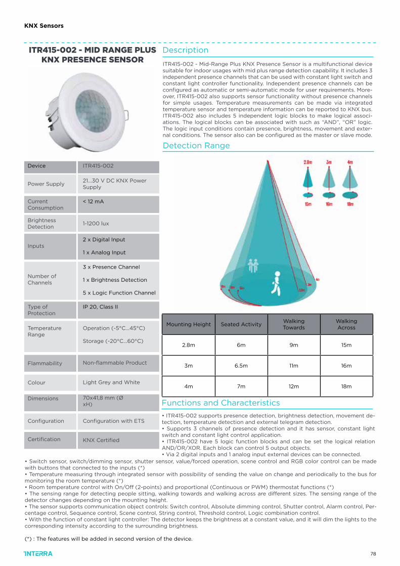
78
KNX Sensors
Power Supply
CurrentConsumption
BrightnessDetection
Inputs
Certification
Number of Channels
Type ofProtection
Flammability
Colour
ITR415-002
21...30 V DC KNX Power Supply
< 12 mA
1-1200 lux
Operation (-5°C...45°C)
Storage (-20°C...60°C)
Non-flammable Product
KNX Certified
Light Grey and White
ITR415-002 - MID RANGE PLUS KNX PRESENCE SENSOR
TemperatureRange
2 x Digital Input
1 x Analog Input
3 x Presence Channel
1 x Brightness Detection
5 x Logic Function Channel
Configuration Configuration with ETS
IP 20, Class II
Device
Dimensions 70x41,8 mm (Ø xH)
Description
ITR415-002 - Mid-Range Plus KNX Presence Sensor is a multifunctional device suitable for indoor usages with mid plus range detection capability. It includes 3 independent presence channels that can be used with constant light switch and constant light controller functionality. Independent presence channels can be configured as automatic or semi-automatic mode for user requirements. More-over, ITR415-002 also supports sensor functionality without presence channels for simple usages. Temperature measurements can be made via integrated temperature sensor and temperature information can be reported to KNX bus. ITR415-002 also includes 5 independent logic blocks to make logical associ-ations. The logical blocks can be associated with such as “AND”, “OR” logic. The logic input conditions contain presence, brightness, movement and exter-nal conditions. The sensor also can be configured as the master or slave mode.
Functions and Characteristics
Detection Range
• ITR415-002 supports presence detection, brightness detection, movement de-tection, temperature detection and external telegram detection.• Supports 3 channels of presence detection and it has sensor, constant light switch and constant light control application.• ITR415-002 have 5 logic function blocks and can be set the logical relation AND/OR/XOR. Each block can control 5 output objects.• Via 2 digital inputs and 1 analog input external devices can be connected.
• Switch sensor, switch/dimming sensor, shutter sensor, value/forced operation, scene control and RGB color control can be made with buttons that connected to the inputs (*)• Temperature measuring through integrated sensor with possibility of sending the value on change and periodically to the bus for monitoring the room temperature (*)• Room temperature control with On/Off (2-points) and proportional (Continuous or PWM) thermostat functions (*)• The sensing range for detecting people sitting, walking towards and walking across are different sizes. The sensing range of the detector changes depending on the mounting height.• The sensor supports communication object controls: Switch control, Absolute dimming control, Shutter control, Alarm control, Per-centage control, Sequence control, Scene control, String control, Threshold control, Logic combination control.• With the function of constant light controller: The detector keeps the brightness at a constant value, and it will dim the lights to the corresponding intensity according to the surrounding brightness.
(*) : The features will be added in second version of the device.
Mounting Height Seated ActivityWalkingTowards
WalkingAcross
2.8m 6m 9m 15m
3m 6.5m 11m 16m
4m 7m 12m 18m
79
KNX Sensors
Useful Installation Tips
Important Notes
Calibration
Mounting
Technical Drawings
As the sensor reacts to temperature changes, the following con-ditions should be avoided:Avoid targeting the sensor toward the objects which may be swayed in the wind, such as curtain, tall plants, miniature etc.Avoid targeting the sensor toward the objects whose surfaces are highly reflective, such as mirror, glass and pool, etc.The sensor should be mounted away from heat sources such as air conditioning, lights, heating vents etc.
• For planning and construction of electric installations the ap-propriate specifications, guidelines and regulations in force of the respective country have to be complied.• Special Programming: ITR415-002 is designed for professional KNX installation. It only can be programmed by ETS software.• Cable Connections: Ensure making correct connections for Black and Red wires.• Voltage: The input voltage shall be 21-30VDC.• Mounting Location: Installed indoors, to avoid installation near the air-conditioner vent, and be away from the heat source.• The tightening torque shall not exceed 0.2Nm.• Avoid contact with liquids and corrosive gases.
There is the option of carrying out a brightness adjustment for the sensor via the brightness detection application with the aid of the ETS parameters and objects.
Calibration Procedure• Perform the measurement during sufficient daylight (> 1/2 * setpoint).• Switch off the light source.• Carry out the measurement of brightness at a defined location with a luxmeter. For instance, lying down at the workplace with a view toward the ceiling and wait until the light is close to being constant. Send the value to the device using the brightness cali-bration object via ETS as soon as possible after measuring.
The device can be mounted either in the ceiling via flush mount-ing housing or on the ceiling via the optionally available sur-face-mounted box.
Flush Mount Process:• First, a slot hole of suitable size for sensor mounting is opened on the ceiling surface to be flush mounted.• Then, KNX cable and input cable, if any, are connected to the relevant connectors on the sensor.• The 2 metal springs on the sensor are stretched and then the sensor is attached to the hole on the ceiling. Thus, mounting pro-cess is finished.
Surface Mount Process (Optional) :• First, a hole of suitable size for cables is opened on the ceiling surface.• Second, the surface junction box where the sensor will be placed is screwed to the ceiling.• Then, KNX cable and input cable, if any, are connected to the relevant connectors on the sensor.• The 2 metal springs on the sensor housing are removed and then the metal tabs are attached to the sensor housing. Then, the sensor is mounted to junction box. Thus, mounting process is completed.
Technical drawings and dimensions for flush mounted and surface mounted sensor models are given below and on the right hand side. All dimensions specified for technical drawings are in milli-meters.
Flush Mounted
Surface Mounted
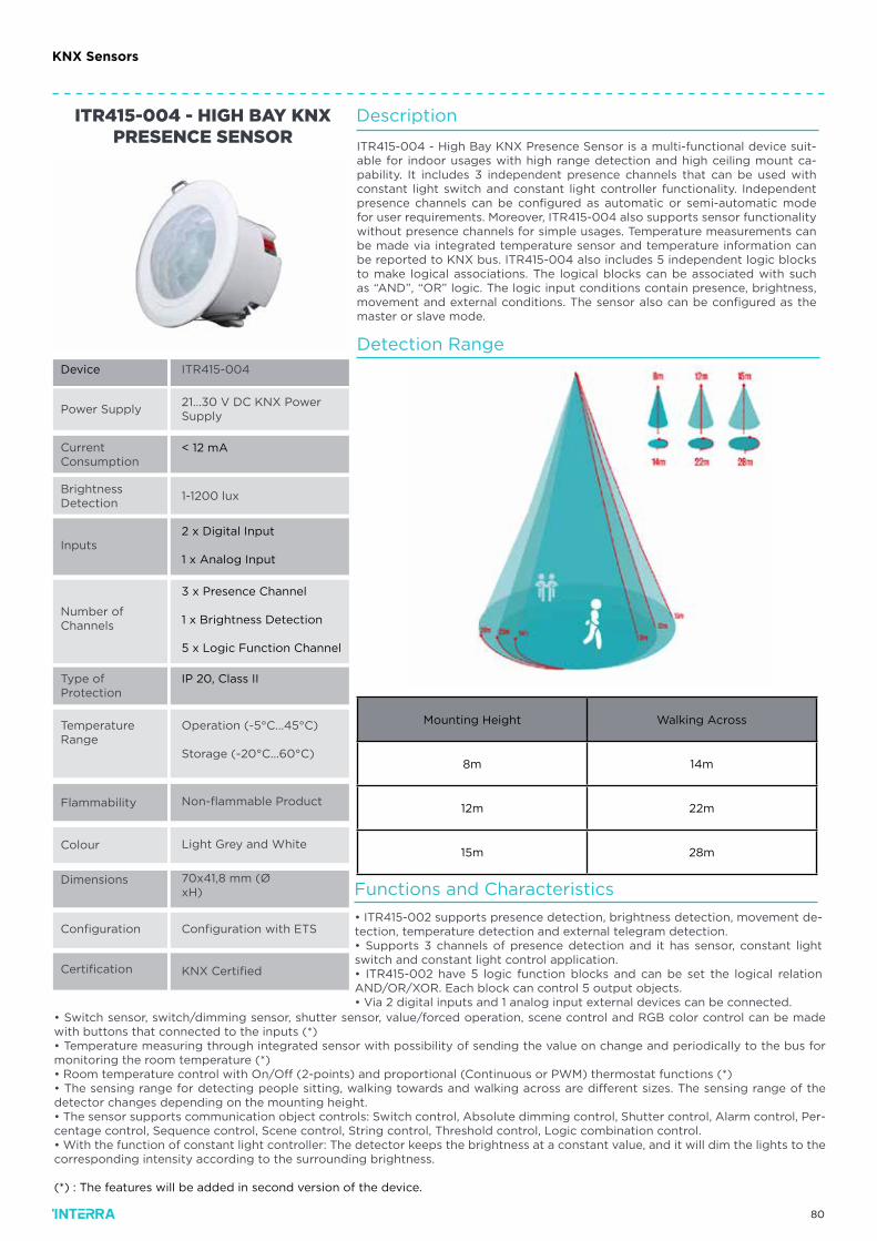
80
KNX Sensors
Power Supply
CurrentConsumption
BrightnessDetection
Inputs
Certification
Number of Channels
Type ofProtection
Flammability
Colour
ITR415-004
21...30 V DC KNX Power Supply
< 12 mA
1-1200 lux
Operation (-5°C...45°C)
Storage (-20°C...60°C)
Non-flammable Product
KNX Certified
Light Grey and White
ITR415-004 - HIGH BAY KNX PRESENCE SENSOR
TemperatureRange
2 x Digital Input
1 x Analog Input
3 x Presence Channel
1 x Brightness Detection
5 x Logic Function Channel
Configuration Configuration with ETS
IP 20, Class II
Device
Dimensions 70x41,8 mm (Ø xH)
Description
ITR415-004 - High Bay KNX Presence Sensor is a multi-functional device suit-able for indoor usages with high range detection and high ceiling mount ca-pability. It includes 3 independent presence channels that can be used with constant light switch and constant light controller functionality. Independent presence channels can be configured as automatic or semi-automatic mode for user requirements. Moreover, ITR415-004 also supports sensor functionality without presence channels for simple usages. Temperature measurements can be made via integrated temperature sensor and temperature information can be reported to KNX bus. ITR415-004 also includes 5 independent logic blocks to make logical associations. The logical blocks can be associated with such as “AND”, “OR” logic. The logic input conditions contain presence, brightness, movement and external conditions. The sensor also can be configured as the master or slave mode.
Functions and Characteristics
Detection Range
• ITR415-002 supports presence detection, brightness detection, movement de-tection, temperature detection and external telegram detection.• Supports 3 channels of presence detection and it has sensor, constant light switch and constant light control application.• ITR415-002 have 5 logic function blocks and can be set the logical relation AND/OR/XOR. Each block can control 5 output objects.• Via 2 digital inputs and 1 analog input external devices can be connected.
• Switch sensor, switch/dimming sensor, shutter sensor, value/forced operation, scene control and RGB color control can be made with buttons that connected to the inputs (*)• Temperature measuring through integrated sensor with possibility of sending the value on change and periodically to the bus for monitoring the room temperature (*)• Room temperature control with On/Off (2-points) and proportional (Continuous or PWM) thermostat functions (*)• The sensing range for detecting people sitting, walking towards and walking across are different sizes. The sensing range of the detector changes depending on the mounting height.• The sensor supports communication object controls: Switch control, Absolute dimming control, Shutter control, Alarm control, Per-centage control, Sequence control, Scene control, String control, Threshold control, Logic combination control.• With the function of constant light controller: The detector keeps the brightness at a constant value, and it will dim the lights to the corresponding intensity according to the surrounding brightness.
(*) : The features will be added in second version of the device.
Mounting Height Walking Across
8m 14m
12m 22m
15m 28m
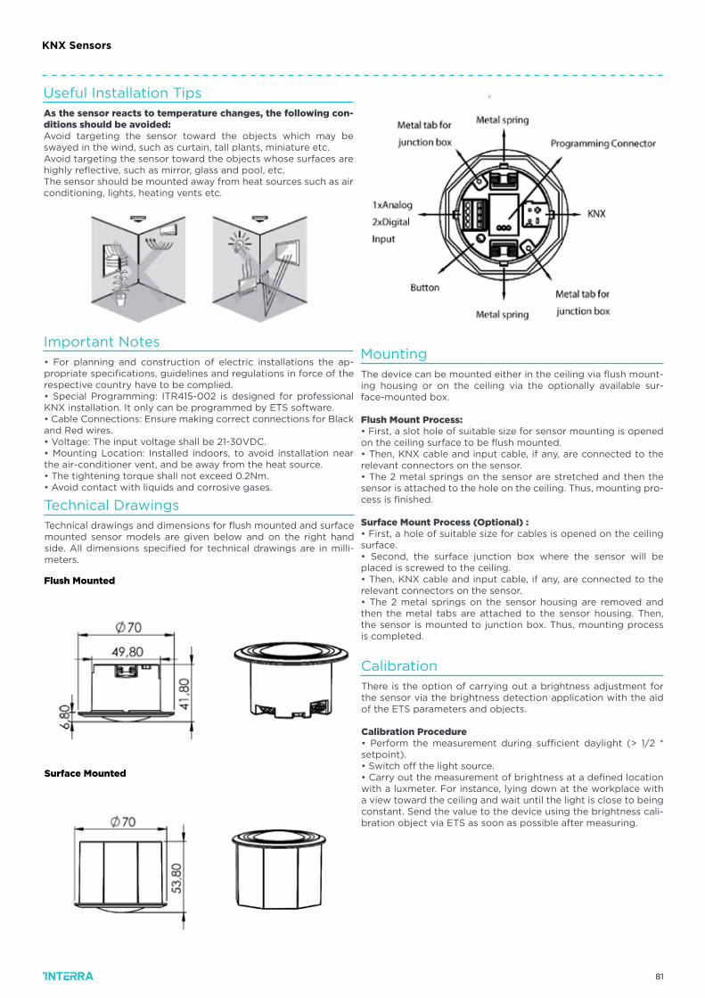
81
KNX Sensors
Useful Installation Tips
Important Notes
Calibration
Mounting
Technical Drawings
As the sensor reacts to temperature changes, the following con-ditions should be avoided:Avoid targeting the sensor toward the objects which may be swayed in the wind, such as curtain, tall plants, miniature etc.Avoid targeting the sensor toward the objects whose surfaces are highly reflective, such as mirror, glass and pool, etc.The sensor should be mounted away from heat sources such as air conditioning, lights, heating vents etc.
• For planning and construction of electric installations the ap-propriate specifications, guidelines and regulations in force of the respective country have to be complied.• Special Programming: ITR415-002 is designed for professional KNX installation. It only can be programmed by ETS software.• Cable Connections: Ensure making correct connections for Black and Red wires.• Voltage: The input voltage shall be 21-30VDC.• Mounting Location: Installed indoors, to avoid installation near the air-conditioner vent, and be away from the heat source.• The tightening torque shall not exceed 0.2Nm.• Avoid contact with liquids and corrosive gases.
There is the option of carrying out a brightness adjustment for the sensor via the brightness detection application with the aid of the ETS parameters and objects.
Calibration Procedure• Perform the measurement during sufficient daylight (> 1/2 * setpoint).• Switch off the light source.• Carry out the measurement of brightness at a defined location with a luxmeter. For instance, lying down at the workplace with a view toward the ceiling and wait until the light is close to being constant. Send the value to the device using the brightness cali-bration object via ETS as soon as possible after measuring.
The device can be mounted either in the ceiling via flush mount-ing housing or on the ceiling via the optionally available sur-face-mounted box.
Flush Mount Process:• First, a slot hole of suitable size for sensor mounting is opened on the ceiling surface to be flush mounted.• Then, KNX cable and input cable, if any, are connected to the relevant connectors on the sensor.• The 2 metal springs on the sensor are stretched and then the sensor is attached to the hole on the ceiling. Thus, mounting pro-cess is finished.
Surface Mount Process (Optional) :• First, a hole of suitable size for cables is opened on the ceiling surface.• Second, the surface junction box where the sensor will be placed is screwed to the ceiling.• Then, KNX cable and input cable, if any, are connected to the relevant connectors on the sensor.• The 2 metal springs on the sensor housing are removed and then the metal tabs are attached to the sensor housing. Then, the sensor is mounted to junction box. Thus, mounting process is completed.
Technical drawings and dimensions for flush mounted and surface mounted sensor models are given below and on the right hand side. All dimensions specified for technical drawings are in milli-meters.
Flush Mounted
Surface Mounted
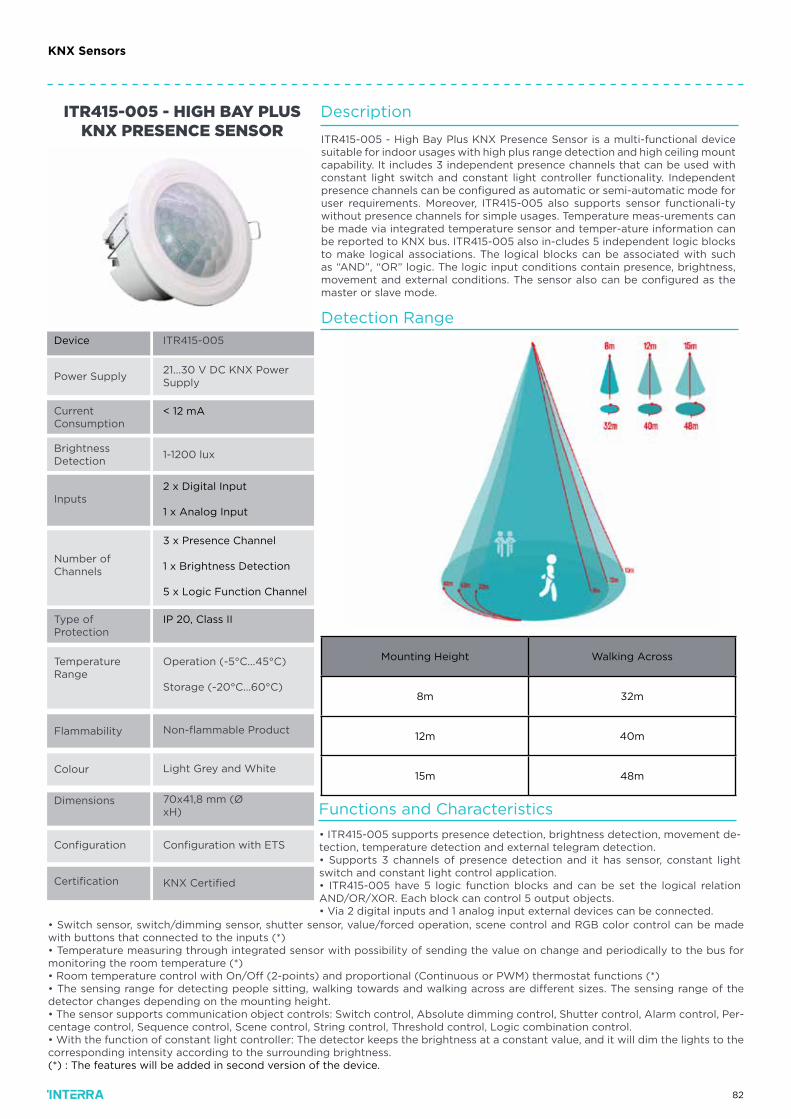
82
Power Supply
CurrentConsumption
BrightnessDetection
Inputs
Certification
Number of Channels
Type ofProtection
Flammability
Colour
ITR415-005
21...30 V DC KNX Power Supply
< 12 mA
1-1200 lux
Operation (-5°C...45°C)
Storage (-20°C...60°C)
Non-flammable Product
KNX Certified
Light Grey and White
ITR415-005 - HIGH BAY PLUS KNX PRESENCE SENSOR
TemperatureRange
2 x Digital Input
1 x Analog Input
3 x Presence Channel
1 x Brightness Detection
5 x Logic Function Channel
Configuration Configuration with ETS
IP 20, Class II
Device
Dimensions 70x41,8 mm (Ø xH)
Description
ITR415-005 - High Bay Plus KNX Presence Sensor is a multi-functional device suitable for indoor usages with high plus range detection and high ceiling mount capability. It includes 3 independent presence channels that can be used with constant light switch and constant light controller functionality. Independent presence channels can be configured as automatic or semi-automatic mode for user requirements. Moreover, ITR415-005 also supports sensor functionali-ty without presence channels for simple usages. Temperature meas-urements can be made via integrated temperature sensor and temper-ature information can be reported to KNX bus. ITR415-005 also in-cludes 5 independent logic blocks to make logical associations. The logical blocks can be associated with such as “AND”, “OR” logic. The logic input conditions contain presence, brightness, movement and external conditions. The sensor also can be configured as the master or slave mode.
Functions and Characteristics
Detection Range
• ITR415-005 supports presence detection, brightness detection, movement de-tection, temperature detection and external telegram detection.• Supports 3 channels of presence detection and it has sensor, constant light switch and constant light control application.• ITR415-005 have 5 logic function blocks and can be set the logical relation AND/OR/XOR. Each block can control 5 output objects.• Via 2 digital inputs and 1 analog input external devices can be connected.
• Switch sensor, switch/dimming sensor, shutter sensor, value/forced operation, scene control and RGB color control can be made with buttons that connected to the inputs (*)• Temperature measuring through integrated sensor with possibility of sending the value on change and periodically to the bus for monitoring the room temperature (*)• Room temperature control with On/Off (2-points) and proportional (Continuous or PWM) thermostat functions (*)• The sensing range for detecting people sitting, walking towards and walking across are different sizes. The sensing range of the detector changes depending on the mounting height.• The sensor supports communication object controls: Switch control, Absolute dimming control, Shutter control, Alarm control, Per-centage control, Sequence control, Scene control, String control, Threshold control, Logic combination control.• With the function of constant light controller: The detector keeps the brightness at a constant value, and it will dim the lights to the corresponding intensity according to the surrounding brightness.(*) : The features will be added in second version of the device.
Mounting Height Walking Across
8m 32m
12m 40m
15m 48m
KNX Sensors
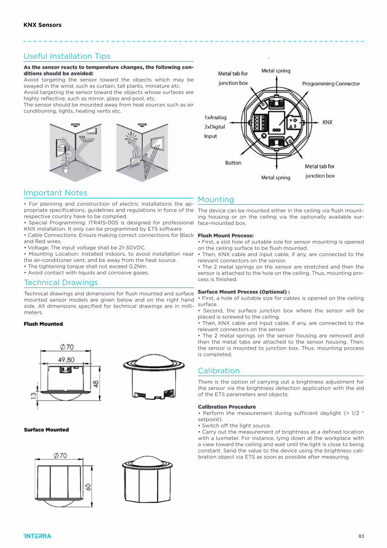
83
Useful Installation Tips
Important Notes
Calibration
Mounting
Technical Drawings
As the sensor reacts to temperature changes, the following con-ditions should be avoided:Avoid targeting the sensor toward the objects which may be swayed in the wind, such as curtain, tall plants, miniature etc.Avoid targeting the sensor toward the objects whose surfaces are highly reflective, such as mirror, glass and pool, etc.The sensor should be mounted away from heat sources such as air conditioning, lights, heating vents etc.
• For planning and construction of electric installations the ap-propriate specifications, guidelines and regulations in force of the respective country have to be complied.• Special Programming: ITR415-005 is designed for professional KNX installation. It only can be programmed by ETS software.• Cable Connections: Ensure making correct connections for Black and Red wires.• Voltage: The input voltage shall be 21-30VDC.• Mounting Location: Installed indoors, to avoid installation near the air-conditioner vent, and be away from the heat source.• The tightening torque shall not exceed 0.2Nm.• Avoid contact with liquids and corrosive gases.
There is the option of carrying out a brightness adjustment for the sensor via the brightness detection application with the aid of the ETS parameters and objects.
Calibration Procedure• Perform the measurement during sufficient daylight (> 1/2 * setpoint).• Switch off the light source.• Carry out the measurement of brightness at a defined location with a luxmeter. For instance, lying down at the workplace with a view toward the ceiling and wait until the light is close to being constant. Send the value to the device using the brightness cali-bration object via ETS as soon as possible after measuring.
The device can be mounted either in the ceiling via flush mount-ing housing or on the ceiling via the optionally available sur-face-mounted box.
Flush Mount Process:• First, a slot hole of suitable size for sensor mounting is opened on the ceiling surface to be flush mounted.• Then, KNX cable and input cable, if any, are connected to the relevant connectors on the sensor.• The 2 metal springs on the sensor are stretched and then the sensor is attached to the hole on the ceiling. Thus, mounting pro-cess is finished.
Surface Mount Process (Optional) :• First, a hole of suitable size for cables is opened on the ceiling surface.• Second, the surface junction box where the sensor will be placed is screwed to the ceiling.• Then, KNX cable and input cable, if any, are connected to the relevant connectors on the sensor.• The 2 metal springs on the sensor housing are removed and then the metal tabs are attached to the sensor housing. Then, the sensor is mounted to junction box. Thus, mounting process is completed.
Technical drawings and dimensions for flush mounted and surface mounted sensor models are given below and on the right hand side. All dimensions specified for technical drawings are in milli-meters.
Flush Mounted
Surface Mounted
KNX Sensors
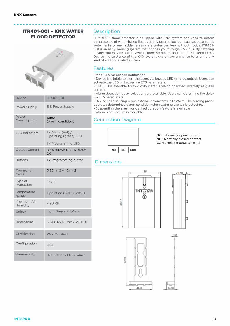
84
LED Indicators
Output Current
Certification
Flammability
Configuration
Buttons
Connection Cable
Temperature Range
Maximum AirHumidity
ITR401-001
EIB Power Supply
10mA (Alarm condition)
1 x Alarm (red) / Operating (green) LED
1 x Programming LED
IP 20
Operation (-40°C…70°C)
KNX Certified
Non-flammable product
ETS
< 90 RH
ITR401-001 – KNX WATER FLOOD DETECTOR
Type ofProtection
0,5A @125V DC, 1A @24V DC
1 x Programming button
Dimensions 55x88,1x21,6 mm (WxHxD)
0,25mm2 – 1,5mm2
Device
Power Supply
PowerConsumption
Colour Light Grey and White
Description
Connection Diagram
Dimensions
Features
ITR401-001 flood detector is equipped with KNX system and used to detect the presence of water-based liquids at any desired location such as basements, water tanks or any hidden areas were water can leak without notice. ITR401-001 is an early warning system that notifies you through KNX bus. By catching it early, you may be able to avoid expensive repairs and loss of treasured items.Due to the existence of the KNX system, users have a chance to arrange any kind of additional alert system.
- Module alive beacon notification.- Device is eligible to alert the users via buzzer, LED or relay output. Users can activate the LED or buzzer via ETS parameters.- The LED is available for two colour status which operated inversely as green and red.- Alarm detection delay selections are available. Users can determine the delay via ETS parameters.- Device has a sensing probe extends downward up to 25cm. The sensing probe operates determined alarm condition when water presence is detected.- Suspending the alarm for desired duration feature is available.- Alarm reset feature is available.
NO : Normally open contactNC : Normally closed contactCOM : Relay mutual terminal
KNX Sensors
85
Output Current
Connection Cable
ITR400-001
12 - 27V DC*
50mA (Alarm Condi-tion, @12 V DC)
ITR400-001 - CONVENTIONAL WATER FLOOD DETECTOR
<90RH
Button
Type of Protection
Operation (0°C…40°C)
Storage (-10°C…75°C)
IP 20
Non-flammable product
1A @24V DC
Device
Power Supply
PowerConsumption
LED Indicators
Temperature Range
Flammability
Light GreyColour
Maximum AirHumidity
1 x Alarm (red) / Operating (green) LED
0,25mm2 - 1.5mm2
Dimensions 55x88,1x21,6 mm (WxHxD)
* : Power supply connection is made independent of negative and positive poles.
Description
The ITR401-001 flood detector is equipped with the KNX system and is used to detect the presence of basements, water tanks, any concealed area or any site where water-based liquids may be leak by infiltrate. The ITR401-001 is used as an early warning system that provides information via integrated components. It protects the users from expensive repairs and from material losses that may be caused by the damage of the goods by detecting liquid leaks early.
Functions and Characteristics
Dimensions & Connection Diagram
• Device is eligible to alert the users via buzzer, LED or relay output. Users can activate the LED or buzzer via jumpers independently.• The LED is available for two colour status which operated inversely as green and red.• Over 2 years lifetime has been provided with MN21 battery (12V - 50mAh, standard battery in the market).• Alarm detection delay selections are available. Immediate/3 sec/6 sec alarm delay selections exist on the device. Users can determine the delay via jumpers.• Device has a sensing probe extends downward up to 25cm. The sensing probe operates determined alarm condition when water presence is detected.
KNX Sensors

86
Wirelessly expand or supplement KNX systemsthe quick and easy way.
KNX RF TechnologyKNX RF Integration: Seamless configuration in ETS.KNX RF Solutions
INTERRA KNX RFThe wireless solution

87
With INTERRA KNX RF, the operating comfort of the building technology can be easily increased at any time in buildings with an existing KNX system.
‘KNX RF’ stands for ‘KNX Radio Frequency’, i.e. KNX via wireless signal.
New options for wirelessly controlling light, blinds, scenes and so on can thus be installed anywhere in the building without a great deal of expense and effort, and above all else without any dirt or noise. Whether it’s a renovation or even a new-build project, operating points can be installed in locations where cables cannot or should not be laid or where switches cannot
or should not be mounted – be this on walls made of stone, concrete, wood, glass or on furniture surfaces.
INTERRA KNX RF uses 100% of the universal KNX standard ‘KNX RF1. R S-Mode’ and allows interoperable access to the full functionality of the KNX system.
This means that all KNX products available on the market can be seamlessly integrated in the system.

88
WirelessTechnologyScrupulously designed, KNX
RF specifications meet the same criteria of interoperability and communication efficiency
than KNX TP. In addition to the KNX Secure mechanisms, KNX
RF is also suitable for energy harvesting.

89
SeamlessIntegrationSmooth integration, thanks to the brand-independent tool ETS, is the main adjective.
Either directly plugging an USB-RF stick in your computer, or by means of a TP/RF media coupler, the KNX Partner will enjoy a great User Experience integrating your KNX RF devices in any project.
That KNX RF has been selected as a technology solution to achieve 95% digital metering by 2020 in World is not a coincidence: future-proof and global widespread ensures the long-term investment.
90
KNX RF Solutions
Device
Power Supply
Current
RadioFrequency
Transmission Power
TransmissionRange
Cable Length
KNX Media
TemperatureAccuracy
Type of Protection
TemperatureRange
Flammability
Type ofProtection
Colour
Dimensions
Certification
Configuration
ITR700-002
230V~ 50/60Hz
30 mA
868,3MHz
< 10dB
In free field: ~100m
Indoors: ~ 30m
< 10m
KNX RF 1.R
±0,3 ºC between -10 ºC & +70 ºC
IP 20, Class II
Operation (-5°C...45°C)
Storage (-15°C...55°C)
Non-flammable Product
Light Grey
IP 20, Class II
46x46x11 mm (HxWxD)
KNX Certified
Configuration with ETS
ITR700-002 - KNX RF 4 CHANNEL
Description
Interra ITR700-002 is a 4-input wireless KNX RF S-Mode universal interface. The 4 channel which can be individually parameterized can be used as analog or binary input. It incorporates up to 4 independent Thermostats for the con-trol of Heating and / or Cooling of 4 different zones. ITR700-002 is a perfect solution for using in conventional installations without placing KNX bus cables. Communication with the KNX Bus must be carried out using a ITR750-002 KNX RF S-Mode media coupler. Interra ITR700-002 KNX RF 4 channel universal in-terface detects the status changes at its inputs and send telegrams according to ETS configuration. In addition, it also allows the measure-ment of the tem-perature and the management of temperature alarms.
Functions and Characteristics
The universal IR codes control TV, DVD and other devices whichcan be controlled by IR• The AC IR codes are used for controlling AC devices of any brand.• Interra IR Emitter supports current detection with current up to 2A.• The device has several AC control types: Fan speed control, swing control, Cooling/Heating, Temperature control, ON/OFF control.• After learned, obtained and downloaded the infrared codesthrough infrared learning page of KNX Assistant Software and IRLearner, the Infrared Emitter can control TV, DVD, air conditioneretc.• Single mode: System emits one universal IR code and the emitting channel is one channel and multichannel.• Repeat mode: System emits one universal IR code several timesrepeatedly and the emitting channel is one channel and multichannel.• Sequence mode: System emits several universal IR code sequently at one time, but the emitting channel is one channel.• Air-condition mode: System control air-condition specially, and the emitting channel is one channel.• Current detection: System detects the current of equipmentsrunning
Installation
The range of the radio signal depends on various external states. The range can be optimized by the choice of installation location avoiding placing it close to any possible sources of interference, e.g. metallic surfaces, micro-wave ovens.
Safety Notes
• Avoid to install it close to radio electrical devices, microwaves,…• Leave a minimum separation of 2m between the transmitter and the receiver.• May be used for indoor installations in dry rooms only.Commisioning
The programming and commissioning must be done with ETS5 or later version:Carry out the wiring according to wiring diagrams described in “layouts and wirings” section.Fig. 1 : Connection to switch / pushbutton.Fig. 2 : Connection to temperature probe.Fig. 3 : Connection to movement detector.-> Supply the interface with 230V. The red LED goes on.-> Press the Programming key (1). The green LED goes on.-> Load the physical address and the application software into the actuator The green LED goes off.
Layouts and Wirings
91
KNX RF Solutions
Device
Power Supply
Battery Life (Esteemed)
RadioFrequency
Transmission Power
TransmissionRange
KNX Media
Maximum AirHumidity
Type of Protection
TemperatureRange
Flammability
Colour
Dimensions
Certification
Configuration
ITR700-001
2 batteries 3V CR2025 (in-cluded)
>8 years
868,3MHz
< 10dBm
In free field: ~100m
Indoors: ~ 30m
KNX-RF S-Mode
< 90 RH
IP 20, Class II
Operation (-5°C...45°C)
Storage (-15°C...55°C)
Light Grey
Non-flammable Product
45x42x12 mm (HxWxD)
KNX Certified
Configuration with ETS
ITR700-001 - KNX RF 2 CHANNEL Description
Interra ITR700-001 is a 2 pushbutton input wireless KNX RF S-Mode transmitter with a built-in temperature sensor. ITR700-001 is a perfect solution for using in conventional installations without placing KNX bus cables. Communication with the KNX Bus must be carried out using a ITR750-002 KNX RF S-Mode media coupler. Interra ITR700-001 KNX RF push button interface detects the statuschanges at its inputs and send telegrams according to ETS configuration. In addition, it also allows the measurement of the temperature and the manage-ment of temperature alarms. Each of 2 inputs can be parameterized individually through the ETS.
Functions and Characteristics
• Acting on 1 or 2 independent output channels.• Function of each input : Switch, Timed Start/Stop, Dimmer, Multiple Switch, Shutter control, Scene control, Fixed value/ Forced.•The Temperature Sensor incorporates different options that must be parameterized: Transmission frequency, over-heating or over-cooling alarms and temperature sensor calibration.• Flush mounting within an universal box, behind a pushbutton.
Installation
Dimensions
Layouts and Wirings
Battery Change
The range of the radio signal depends on various external states. Therange can be optimized by the choice of installation location avoiding placing it close to any possible sources of interference, e.g. metallicsurfaces, microwave ovens
Safety Notes
• Avoid to install it close to radio electrical devices, microwaves,…• Leave a minimum separation of 2m between the transmitter and the receiver.• May be used for indoor installations in dry rooms only
When the battery reaches the limit of its life, ITR700-001 sends a warningtelegram to KNX bus. To replace the battery (Fig. 1) release the cover ofthe sensor with the help of a screwdriver. Insert it into the upper slot.Remove the cover of the socle and remove the battery being careful withthe components of the printed circuit.
TemperatureAccuracy
±0,3 ºC between -10 ºC & +70 ºC

92
Layouts and Wirings
Device
Power Supply
Consumption
Type of Load
Relay BreakingCapacity
MaximumCapacity
1/10V Maximum Input Current
1/10V Maximum Output Current
Transmission Power
Transmission Range
Radio Frequency
Colour
Dimensions
Certification
Configuration
ITR710-003
2 batteries 3V CR2025 (in-cluded)
>8 years
868,3MHz
< 10dBm
In free field: ~100m
Indoors: ~ 30m
KNX-RF S-Mode
< 90 RH
IP 20, Class II
Operation (-5°C...45°C)
Storage (-15°C...55°C)
Light Grey
Non-flammable Product
45x42x12 mm (HxWxD)
KNX Certified
Configuration with ETS
KNX RF 1 CHANNEL 110 V DC BALLAST DIMMER
PUSH BUTTON INTERFACEDIMMER
UNIVERSAL INTERFACE
DescriptionInterra ITR710-003 is a one channel KNX RF S-Mode wirelessDimming actuator for 1/10VDC Drivers or Ballasts, with LED orFluorescence lighting. ITR710-003 is a perfect solution for using inconventional installations without placing KNX bus cables with its bidirectional KNX RF communication functionality. Communication withthe KNX Bus must be carried out using a ITR750-002 KNX RF S-Modemedia coupler. ITR710-003 has an integrated KNX-RF signal repeateroptionally. It can be used to extend the distance between devices
Functions and Characteristics
• Time of soft on and off, maximum and minimum dimming level, behavior after on telegram functions can be configured via ETS.• Staircase time switch and sequential operation modes.• The connection of an auxiliary pushbutton (optional) allows localcontrol of the actuator or some other wireless actuator or connected to the bus, as parameterized in the ETS.• Possibility to configure the state in which it returns after a power fault.• It has a programming button (1) to carry out its programming.• Up to 5 Scenes can be stored / called up.• Programming and commissioning by ETS5 via the KNX-RF USB stick ITR755-001.• Flush mounted in junction box.
Installation
Commisioning
Warning: Disconnect the main supply before the installation!• Install the dimming actuator according to the schematics / wiringdiagram.• The auxiliary pushbutton input (4) is optional. Can be used for local control of the actual actuator or other wireless actuators connected tothe bus (de-pending on configuration within ETS).• Before reconnecting the device to the power, verify correct installation and wiring.• The range of the radio signal depends on various external circumstances. The range can be optimized by the choice of installation location, avoiding placing it close to any possible sources of interference, e.g. metallic surfaces, microwave ovens, etc.Note : Output contact (L’) which allows disconnecting physically the lamps.L’ output is a relay contact that opens or closes the power supply to the bal-lasts/drivers. Installation can be made without using the relay L‘ as long as for the user is indifferent that the lamps remain at their minimum brightness and keep continuously supplied, or if the off is done by another external breaking device.
Safety Notes
-> Avoid to install it close to radio electrical devices, microwaves,…-> Leave a minimum separation of 2m between the transmitter and the receiver.-> May be used for indoor installations in dry rooms only.
KNX Media ±0,3 ºC between -10 ºC & +70 ºC
Type of Protection
TemperatureRange
IP 20, Class II
Operation (-5°C...45°C)
Storage (-15°C...55°C)
The programming and commissioning must be done with ETS5 or laterversion:Carry out the wiring according to wiring diagrams described in “layouts and wirings” section.-> Supply the actuator. The red LED (3) goes on.-> Press the programming button (1). The green LED goes on.-> Transmit physical address and configuration from ETS to device. After suc-cessful download the green LED (2) turns off.Note : The first time the actuator is connected to the mains, as well asafter a hard reset, the red and green LED will flash quickly).
93
Device
Power Supply
Current
RadioFrequency
Transmission Power
TransmissionRange
Cable Length
KNX Media
MaximumLoad
Type of Protection
TemperatureRange
Valid for
Type ofProtection
Colour
Dimensions
Certification
Configuration
ITR710-002
12-48V DC
< 12 mA
868,3MHz
< 10dBm
In free field: ~100m
Indoors: ~ 30m
< 10m
KNX RF 1.R
8A (12V: 96W // 24V: 192W)
IP 20, Class II
Operation (-5°C...45°C)
Storage (-15°C...55°C)
Single-color low-voltage LED strips
Light Grey
IP 20, Class II
46x46x11 mm (HxWxD)
KNX Certified
Configuration with ETS
ITR710-002 - KNX RF 1 CHANNEL LED STRIP
DIMMERUNIVERSAL INTERFACE
DescriptionInterra ITR710-002 is a one channel KNX RF S-Mode wireless dimming actuator for single-color low voltage LED strips. It allowsswitching on, switching off and dimming the LED strips. ITR710-002 is a perfect solution for using in conven-tional installations without placing KNX bus cables with its bi-directional KNX RF communication functionality. Communication with the KNX Bus must be carried out using a ITR750-002 KNX RF S-Mode media coupler. Interra ITR710-002 has an integrated KNX-RF signal repeater optionally. It can be used to ex-tend the distance between devices.
Functions and Characteristics
Time of soft on and off, maximum and minimum dimming level, behavior after on telegram functions can be configured via ETS.• Staircase time switch and sequential operation modes.• The connection of an auxiliary pushbutton (optional) allows local control of the actuator or some other wireless actuator or connected to the bus, as parameterized in the ETS.• Possibility to configure the state in which it returns after a power fault.• It has a programming button (1) to carry out its programming.• Up to 5 Scenes can be stored / called up.• Programming and commissioning by ETS5 via the KNX-RF USB stick ITR755-001.• Flush mounted in junction box.
Installation
Comissioning
Warning: Disconnect the main supply before the installation!• Install the dimming actuator according to the schematics / wiring diagram.• The auxiliary pushbutton input (4) is optional. Can be used for local control of the actual actuator or other wireless actuators connected to the bus (de-pending on configuration within ETS).• Before reconnecting the device to the power, verify correct installation and wiring.• The range of the radio signal depends on various external circumstances. The range can be optimized by the choice of installation location, avoiding placing it close to any possible sources of interference, e.g. metallic surfaces, microwave ovens, etc.
The programming and commissioning must be done with ETS5 or later ver-sion: Carry out the wiring according to wiring diagrams described in “layouts andwirings” section.-> After successful installation set device in operation (by reconnectingsupply voltage).-> Supply the actuator. The red LED (3) goes on.-> Press the programming button (1). The green LED goes on.-> Transmit physical address and configuration from ETS to device.-> After successful download the green LED (2) turns off.Note : The first time the actuator is connected to the mains, as well as aftera hard reset, the red and green LED will flash quickly).
Safety Notes
> Avoid to install it close to radio electrical devices, microwaves,…-> Leave a minimum separation of 2m between the transmitter and the receiver.-> May be used for indoor installations in dry rooms only.
Layouts and Wirings
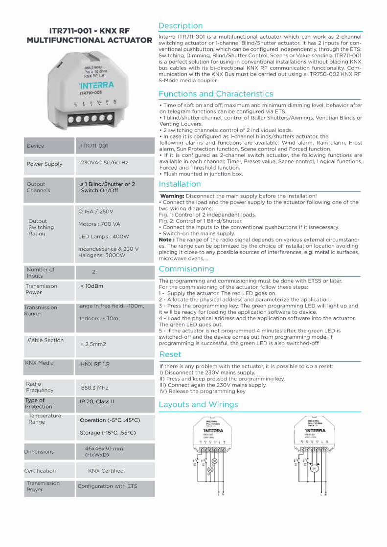
94
Device
Power Supply
OutputChannels
Output Switching Rating
Number of Inputs
TransmissionPower
TransmissonPower
Transmission Range
KNX Media
TemperatureRange
Dimensions
Certification
ITR711-001
230VAC 50/60 Hz
s 1 Blind/Shutter or 2 Switch On/Off
μ 16A / 250V
Motors : 700 VA
LED Lamps : 400W
Incandescence & 230 V Halogens: 3000W
2
ange In free field: ~100m,
Indoors: ~ 30m
≤ 2,5mm2
46x46x30 mm (HxWxD)
868,3 MHz
Configuration with ETS
KNX Certified
ITR711-001 - KNX RF MULTIFUNCTIONAL ACTUATOR
DescriptionInterra ITR711-001 is a multifunctional actuator which can work as 2-channel switching actuator or 1-channel Blind/Shutter actuator. It has 2 inputs for con-ventional pushbutton, which can be configured independently, through the ETS: Switching, Dimming, Blind/Shutter Control, Scenes or Value sending. ITR711-001 is a perfect solution for using in conventional installations without placing KNX bus cables with its bi-directional KNX RF communication functionality. Com-munication with the KNX Bus must be carried out using a ITR750-002 KNX RFS-Mode media coupler.
Functions and Characteristics
• Time of soft on and off, maximum and minimum dimming level, behavior after on telegram functions can be configured via ETS.• 1 blind/shutter channel: control of Roller Shutters/Awnings, Venetian Blinds or Venting Louvers.• 2 switching channels: control of 2 individual loads.• In case it is configured as 1-channel blinds/shutters actuator, thefollowing alarms and functions are available: Wind alarm, Rain alarm, Frost alarm, Sun Protection function, Scene control and Forced function.• If it is configured as 2-channel switch actuator, the following functions are available in each channel: Timer, Preset value, Scene control, Logical functions, Forced and Threshold function.• Flush mounted in junction box.
Installation
Commisioning
Reset
Layouts and Wirings
Cable Section
KNX RF 1.R
RadioFrequency
Type ofProtection
IP 20, Class II
Operation (-5°C...45°C)
Storage (-15°C...55°C)
Warning: Disconnect the main supply before the installation!• Connect the load and the power supply to the actuator following one of the two wiring diagrams:Fig. 1: Control of 2 independent loads.Fig. 2: Control of 1 Blind/Shutter.• Connect the inputs to the conventional pushbuttons if it isnecessary.• Switch-on the mains supply.Note : The range of the radio signal depends on various external circumstanc-es. The range can be optimized by the choice of installation location avoiding placing it close to any possible sources of interferences, e.g. metallic surfaces, microwave ovens,...
The programming and commissioning must be done with ETS5 or later.For the commissioning of the actuator, follow these steps:1 - Supply the actuator. The red LED goes on.2 - Allocate the physical address and parameterize the application.3 - Press the programming key. The green programming LED will light up and it will be ready for loading the application software to device.4 - Load the physical address and the application software into the actuator. The green LED goes out.5 - If the actuator is not programmed 4 minutes after, the green LED is switched-off and the device comes out from programming mode. Ifprogramming is successful, the green LED is also switched-off
If there is any problem with the actuator, it is possible to do a reset:I) Disconnect the 230V mains supply.II) Press and keep pressed the programming key.III) Connect again the 230V mains supply.IV) Release the programming key
< 10dBm
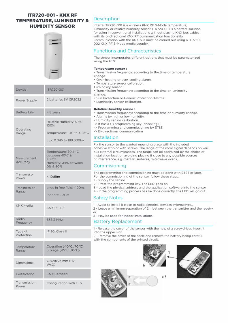
95
Installation
Commisioning
Safety Notes
Battery Replacement
Fix the sensor to the wanted mounting place with the includedadhesive strip or with screws. The range of the radio signal depends on vari-ous external circumstances. The range can be optimized by the choice ofInstallation location avoiding placing it close to any possible sourcesof interference, e.g. metallic surfaces, microwave ovens,…
The programming and commissioning must be done with ETS5 or later.For the commissioning of the sensor, follow these steps:1 - Supply the sensor.2 - Press the programming key. The LED goes on.3 - Load the physical address and the application software into the sensor4 - If the programming process has be done correctly, the LED will go out.
1 - Avoid to install it close to radio electrical devices, microwaves,…2 - Leave a minimum separation of 2m between the transmitter and the receiv-er.3 - May be used for indoor installations.
1 - Release the cover of the sensor with the help of a screwdriver. Insert itinto the upper slot.2 - Remove the cover of the socle and remove the battery being carefulwith the components of the printed circuit.
Device
Power Supply
Battery Life
OperatingRange
MeasurementAccuracy
TransmissionPower
TransmissonPower
Transmission Range
RadioFrequency
TemperatureRange
Dimensions
Certification
ITR720-001
2 batteries 3V CR2032
> 8 years
Relative Humidity: 0 to 100%
Temperature: –40 to +125°C
Lux: 0.045 to 188,000lux
Temperature: ±0,4º C between -10ºC &+85ºCHumidity: ±4% between 0% & 80%
ange In free field: ~100m,
Indoors: ~ 30m
KNX RF 1.R
78x28x23 mm (Hx-WxD)
Configuration with ETS
KNX Certified
ITR720-001 - KNX RF TEMPERATURE, LUMINOSITY &
HUMIDITY SENSOR
DescriptionInterra ITR720-001 is a wireless KNX RF S-Mode temperature,luminosity or relative humidity sensor. ITR720-001 is a perfect solutionfor using in conventional installations without placing KNX bus cableswith its bi-directional KNX RF communication functionality.Communication with the KNX bus must be carried out using a ITR750-002 KNX RF S-Mode media coupler.
Functions and Characteristics
The sensor incorporates different options that must be parameterizedusing the ETS:
Temperature sensor :• Transmission frequency: according to the time or temperaturechange• Over-heating or over-cooling alarms.• Temperature sensor calibration.Luminosity sensor :• Transmission frequency: according to the time or luminositychange.• Sun Protection or Generic Protection Alarms.• Luminosity sensor calibration.
Relative Humidity sensor :• Transmission frequency: according to the time or humidity change.• Alarms by high or low humidity.• Humidity sensor calibration.-> It has a (1) programming key (check fig.1).-> Programming and commissioning by ETS5.-> Bi-directional communication
KNX Media
868,3 MHz
Type ofProtection
Operation (-10°C...70°C)Storage (-15°C...85°C)
< 10dBm
IP 20, Class II
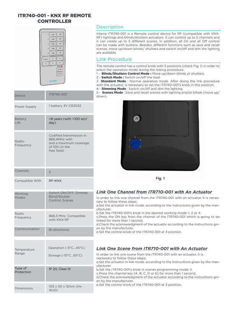
96
Device
Power Supply
BatteryLife
Radio-Frequency
Channels
Compatible With
Working Modes
Communication
Dimensions
ITR740-001
1 battery 3V CR2032
>8 years (with <100 act/day)
Codified transmission in 868,4MHz withand a maximum coverage of 100 (in thefree field)
5
Switch ON/OFF, Dimmer, Blind/ShutterControl, Scenes
868,3 MHz. Compatible with KNX-RF
105 x 50 x 12mm (Hx-WxD)
Operation (-5°C...45°C)
Storage (-15°C...65°C)
ITR740-001 - KNX RF REMOTE CONTROLLER
Description
Link One Channel from ITR710-001 with An Actuator
Link One Scene from ITR710-001 with An Actuator
Link Procedure
Interra ITR740-001 is a Remote control device for RF (compatible with KNX-RF) lightings and blinds/shutters actuators. It can control up to 5 channels and it can create up to 5 different scenes. In addition, all On and all Off control can be made with buttons. Besides, different functions such as save and recall scenes, move up/down blinds/ shutters and switch on/off and dim the lighting are available.
In order to link one channel from the ITR740-001 with an actuator, it is neces-sary to follow these steps:a.Set the actuator in link mode, according to the instructions given by the man-ufacturer.b.Set the ITR740-001’s knob in the desired working mode: 1, 2 or 4.c.Press the ON key from the channel of the ITR740-001 which is going to be linked for more than 1 second.d.Check the acknowledgment of the actuator according to the instructions giv-en by the manufacturer.e.Set the control knob of the ITR740-001 at 3 position.
In order to link one scene from the ITR740-001 with an actuator, it isnecessary to follow these steps:a.Set the actuator in link mode, according to the instructions given by the man-ufacturer.b.Set the ITR740-001’s knob in scenes programming mode: 5.c.Press the channel key (A, B, C, D or E) for more than 1 second.d.Check the acknowledgment of the actuator according to the instructions giv-en by the manufacturer.e.Set the control knob of the ITR740-001 at 3 position.
The remote control has a control knob with 5 positions (check Fig. 1) in order to select the operation mode during the linking procedure:1 - Blinds/Shutters Control Mode : Move up/down blinds or shutters.2 - Switch Mode : Switch on/off the load.3 -Standard Mode : Normal operation mode. After doing the link procedure with the actuator, is necessary to set the ITR740-001’s knob in this position.4 - Dimming Mode : Switch on/off and dim the lighting.5 - Scenes Mode : Save and recall scenes with lighting and/or blinds (move up/down).
Radio Frequency
Bi-directiona
Temperature Range
Type ofProtection
IP 20, Class III
RF-KNX
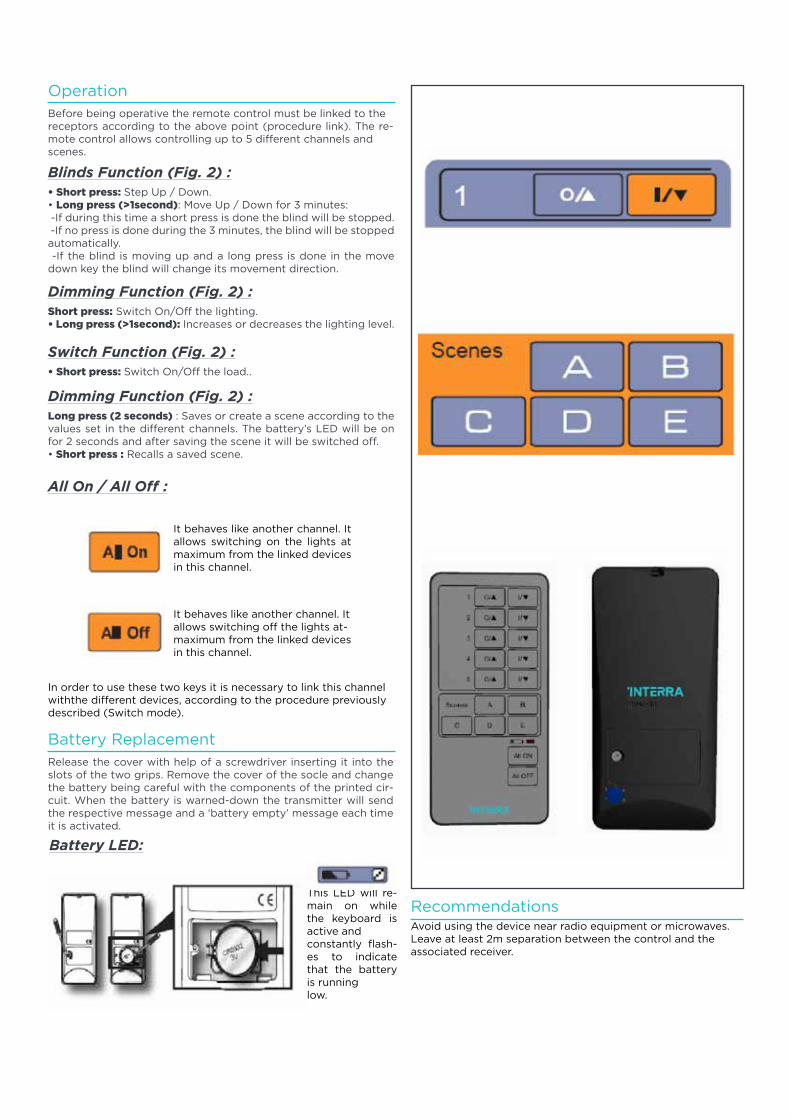
97
Operation
Battery Replacement
Recommendations
Blinds Function (Fig. 2) :
Before being operative the remote control must be linked to thereceptors according to the above point (procedure link). The re-mote control allows controlling up to 5 different channels andscenes.
Release the cover with help of a screwdriver inserting it into the slots of the two grips. Remove the cover of the socle and change the battery being careful with the components of the printed cir-cuit. When the battery is warned-down the transmitter will send the respective message and a ‘battery empty’ message each time it is activated.
• Short press: Step Up / Down.• Long press (>1second): Move Up / Down for 3 minutes: -If during this time a short press is done the blind will be stopped. -If no press is done during the 3 minutes, the blind will be stoppedautomatically. -If the blind is moving up and a long press is done in the move down key the blind will change its movement direction.
Dimming Function (Fig. 2) :
Dimming Function (Fig. 2) :
All On / All Off :
Battery LED:
Switch Function (Fig. 2) :
Short press: Switch On/Off the lighting.• Long press (>1second): Increases or decreases the lighting level.
Long press (2 seconds) : Saves or create a scene according to thevalues set in the different channels. The battery’s LED will be on for 2 seconds and after saving the scene it will be switched off.• Short press : Recalls a saved scene.
• Short press: Switch On/Off the load..
It behaves like another channel. It allows switching on the lights at maximum from the linked devices in this channel.
It behaves like another channel. It allows switching off the lights at-maximum from the linked devices in this channel.
In order to use these two keys it is necessary to link this channel withthe different devices, according to the procedure previously described (Switch mode).
This LED will re-main on while the keyboard is active andconstantly flash-es to indicate that the battery is runninglow.
Avoid using the device near radio equipment or microwaves.Leave at least 2m separation between the control and the associated receiver.
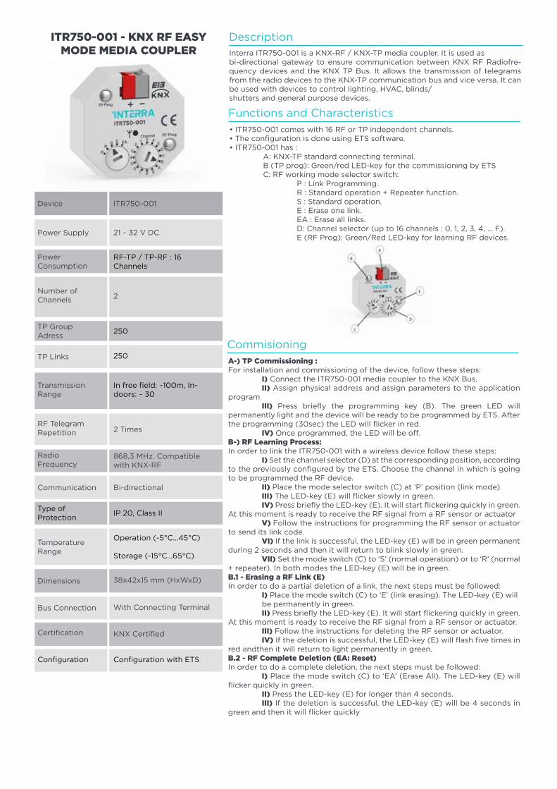
98
Device
Power Supply
PowerConsumption
Number ofChannels
TP GroupAdress
Certification
TP Links
Transmission Range
RadioFrequency
TemperatureRange
Dimensions
Bus Connection
ITR750-001
21 ~ 32 V DC
RF-TP / TP-RF : 16 Channels
2
2 Times
38x42x15 mm (HxWxD)
Bi-directional
KNX Certified
With Connecting Terminal
ITR750-001 - KNX RF EASY MODE MEDIA COUPLER
RF TelegramRepetition
868,3 MHz. Compatible with KNX-RF
Communication
Type ofProtection
IP 20, Class II
Operation (-5°C...45°C)
Storage (-15°C...65°C)
250
250
Configuration Configuration with ETS
In free field: ~100m, In-doors: ~ 30
DescriptionInterra ITR750-001 is a KNX-RF / KNX-TP media coupler. It is used asbi-directional gateway to ensure communication between KNX RF Radiofre-quency devices and the KNX TP Bus. It allows the transmission of telegrams from the radio devices to the KNX-TP communication bus and vice versa. It can be used with devices to control lighting, HVAC, blinds/shutters and general purpose devices.
Functions and Characteristics
Commisioning
• ITR750-001 comes with 16 RF or TP independent channels.• The configuration is done using ETS software.• ITR750-001 has : A: KNX-TP standard connecting terminal. B (TP prog): Green/red LED-key for the commissioning by ETS C: RF working mode selector switch: P : Link Programming. R : Standard operation + Repeater function. S : Standard operation. E : Erase one link. EA : Erase all links. D: Channel selector (up to 16 channels : 0, 1, 2, 3, 4, … F). E (RF Prog): Green/Red LED-key for learning RF devices.
A-) TP Commissioning :For installation and commissioning of the device, follow these steps: I) Connect the ITR750-001 media coupler to the KNX Bus. II) Assign physical address and assign parameters to the application program III) Press briefly the programming key (B). The green LED will permanently light and the device will be ready to be programmed by ETS. After the programming (30sec) the LED will flicker in red. IV) Once programmed, the LED will be off.B-) RF Learning Process:In order to link the ITR750-001 with a wireless device follow these steps: I) Set the channel selector (D) at the corresponding position, according to the previously configured by the ETS. Choose the channel in which is going to be programmed the RF device. II) Place the mode selector switch (C) at ‘P’ position (link mode). III) The LED-key (E) will flicker slowly in green. IV) Press briefly the LED-key (E). It will start flickering quickly in green. At this moment is ready to receive the RF signal from a RF sensor or actuator V) Follow the instructions for programming the RF sensor or actuator to send its link code. VI) If the link is successful, the LED-key (E) will be in green permanent during 2 seconds and then it will return to blink slowly in green. VII) Set the mode switch (C) to ‘S’ (normal operation) or to ‘R’ (normal + repeater). In both modes the LED-key (E) will be in green.B.1 - Erasing a RF Link (E)In order to do a partial deletion of a link, the next steps must be followed: I) Place the mode switch (C) to ‘E’ (link erasing). The LED-key (E) will be permanently in green. II) Press briefly the LED-key (E). It will start flickering quickly in green. At this moment is ready to receive the RF signal from a RF sensor or actuator. III) Follow the instructions for deleting the RF sensor or actuator. IV) If the deletion is successful, the LED-key (E) will flash five times in red andthen it will return to light permanently in green.B.2 - RF Complete Deletion (EA: Reset)In order to do a complete deletion, the next steps must be followed: I) Place the mode switch (C) to ‘EA’ (Erase All). The LED-key (E) will flicker quickly in green. II) Press the LED-key (E) for longer than 4 seconds. III) If the deletion is successful, the LED-key (E) will be 4 seconds in green and then it will flicker quickly
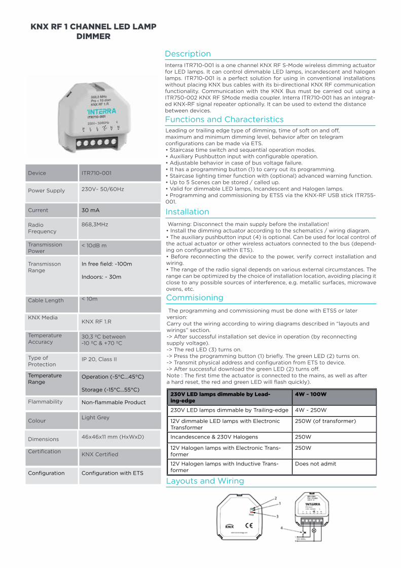
99
Device
Power Supply
Current
RadioFrequency
TransmissionPower
Certification
TransmissonRange
Cable Length
TemperatureAccuracy
Flammability
Colour
Dimensions
ITR710-001
230V~ 50/60Hz
30 mA
868,3MHz
< 10dB m
< 10m
KNX RF 1.R
Light Grey
IP 20, Class II
KNX Certified
46x46x11 mm (HxWxD)
KNX RF 1 CHANNEL LED LAMP DIMMER
DescriptionInterra ITR710-001 is a one channel KNX RF S-Mode wireless dimming actuator for LED lamps. It can control dimmable LED lamps, incandescent and halogen lamps. ITR710-001 is a perfect solution for using in conventional installations without placing KNX bus cables with its bi-directional KNX RF communication functionality. Communication with the KNX Bus must be carried out using a ITR750-002 KNX RF SMode media coupler. Interra ITR710-001 has an integrat-ed KNX-RF signal repeater optionally. It can be used to extend the distancebetween devices.
Leading or trailing edge type of dimming, time of soft on and off,maximum and minimum dimming level, behavior after on telegramconfigurations can be made via ETS.• Staircase time switch and sequential operation modes.• Auxiliary Pushbutton input with configurable operation.• Adjustable behavior in case of bus voltage failure.• It has a programming button (1) to carry out its programming.• Staircase lighting timer function with (optional) advanced warning function.• Up to 5 Scenes can be stored / called up.• Valid for dimmable LED lamps, Incandescent and Halogen lamps.• Programming and commissioning by ETS5 via the KNX-RF USB stick ITR755-001.
Warning: Disconnect the main supply before the installation!• Install the dimming actuator according to the schematics / wiring diagram.• The auxiliary pushbutton input (4) is optional. Can be used for local control of the actual actuator or other wireless actuators connected to the bus (depend-ing on configuration within ETS).• Before reconnecting the device to the power, verify correct installation and wiring.• The range of the radio signal depends on various external circumstances. The range can be optimized by the choice of installation location, avoiding placing it close to any possible sources of interference, e.g. metallic surfaces, microwave ovens, etc.
The programming and commissioning must be done with ETS5 or laterversion:Carry out the wiring according to wiring diagrams described in “layouts andwirings” section.-> After successful installation set device in operation (by reconnectingsupply voltage).-> The red LED (3) turns on.-> Press the programming button (1) briefly. The green LED (2) turns on.-> Transmit physical address and configuration from ETS to device.-> After successful download the green LED (2) turns off.Note : The first time the actuator is connected to the mains, as well as aftera hard reset, the red and green LED will flash quickly).
Functions and Characteristics
Installation
Commisioning
Layouts and Wiring
KNX Media
±0,3 ºC between -10 ºC & +70 ºC
Type ofProtection
TemperatureRange
Operation (-5°C...45°C)
Storage (-15°C...55°C)
Non-flammable Product
In free field: ~100m
Indoors: ~ 30m
Configuration Configuration with ETS
230V LED lamps dimmable by Lead-ing-edge
4W ~ 100W
230V LED lamps dimmable by Trailing-edge 4W ~ 250W
12V dimmable LED lamps with Electronic Transformer
250W (of transformer)
Incandescence & 230V Halogens 250W
12V Halogen lamps with Electronic Trans-former
250W
12V Halogen lamps with Inductive Trans-former
Does not admit
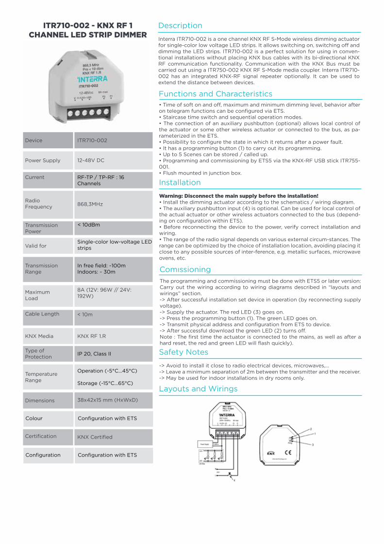
100
Safety Notes
Layouts and Wirings
Description
Installation
Comıssioning
-> Avoid to install it close to radio electrical devices, microwaves,…-> Leave a minimum separation of 2m between the transmitter and the receiver.-> May be used for indoor installations in dry rooms only.
Interra ITR710-002 is a one channel KNX RF S-Mode wireless dimming actuator for single-color low voltage LED strips. It allows switching on, switching off and dimming the LED strips. ITR710-002 is a perfect solution for using in conven-tional installations without placing KNX bus cables with its bi-directional KNX RF communication functionality. Communication with the KNX Bus must be carried out using a ITR750-002 KNX RF S-Mode media coupler. Interra ITR710-002 has an integrated KNX-RF signal repeater optionally. It can be used to extend the distance between devices.
Warning: Disconnect the main supply before the installation!• Install the dimming actuator according to the schematics / wiring diagram.• The auxiliary pushbutton input (4) is optional. Can be used for local control of the actual actuator or other wireless actuators connected to the bus (depend-ing on configuration within ETS).• Before reconnecting the device to the power, verify correct installation and wiring.• The range of the radio signal depends on various external circum-stances. The range can be optimized by the choice of installation location, avoiding placing it close to any possible sources of inter-ference, e.g. metallic surfaces, microwave ovens, etc.
The programming and commissioning must be done with ETS5 or later version:Carry out the wiring according to wiring diagrams described in “layouts and wirings” section.-> After successful installation set device in operation (by reconnecting supply voltage).-> Supply the actuator. The red LED (3) goes on.-> Press the programming button (1). The green LED goes on.-> Transmit physical address and configuration from ETS to device.-> After successful download the green LED (2) turns off.Note : The first time the actuator is connected to the mains, as well as after a hard reset, the red and green LED will flash quickly).
Functions and Characteristics• Time of soft on and off, maximum and minimum dimming level, behavior after on telegram functions can be configured via ETS.• Staircase time switch and sequential operation modes.• The connection of an auxiliary pushbutton (optional) allows local control of the actuator or some other wireless actuator or connected to the bus, as pa-rameterized in the ETS.• Possibility to configure the state in which it returns after a power fault.• It has a programming button (1) to carry out its programming.• Up to 5 Scenes can be stored / called up.• Programming and commissioning by ETS5 via the KNX-RF USB stick ITR755-001.• Flush mounted in junction box.
Device
Power Supply
Current
RadioFrequency
Transmission Power
Certification
Valid for
Transmission Range
Cable Length
TemperatureRange
Dimensions
ITR710-002
12-48V DC
RF-TP / TP-RF : 16 Channels
868,3MHz
8A (12V: 96W // 24V: 192W)
38x42x15 mm (HxWxD)
KNX RF 1.R
KNX Certified
ITR710-002 - KNX RF 1 CHANNEL LED STRIP DIMMER
MaximumLoad
< 10m
KNX Media
Type ofProtection
IP 20, Class II
Operation (-5°C...45°C)
Storage (-15°C...65°C)
< 10dBm
Single-color low-voltage LED strips
Colour
Configuration
Configuration with ETS
Configuration with ETS
In free field: ~100mIndoors: ~ 30m
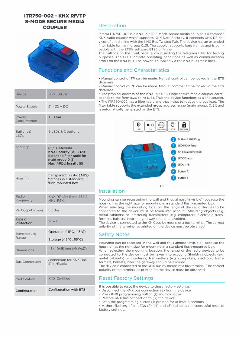
101
Power Supply
PowerConsumption
Buttons & LEDs
Security
Certification
Housing
RadioFrequency
TemperatureRange
Dimensions
Bus Connection
ITR750-002Device
21 ~ 32 V DC
< 10 mA
9 LEDs & 2 buttons
48x40x18 mm (HxWxD)
6 dBm
KNX Certified
Connection for KNX Bus (Red/Black)
ITR750-002 - KNX RF/TP S-MODE SECURE MEDIA
COUPLER
KNX RF, ISM Band 868,3 MHz, FSK
RF Output Power
Type ofProtection
IP 20
Operation (-5°C...45°C)
Storage (-15°C...65°C)
RF/TP MediumKNX Security (AES-128)Extended filter table for main group 0..31Max. APDU length: 55
Transparent plastic (ABS)Matches in a standard flush-mounted box
Configuration Configuration with ETS
Description
Functions and Characteristics
Installation
Safety Notes
Reset Factory Settings
Interra ITR750-002 is a KNX RF/TP S-Mode secure media coupler is a compact KNX radio coupler which supports KNX Data Security. It connects KNX RF de-vices of a radio line with the KNX Bus Twisted Pair. The device has an extended filter table for main group 0..31. The coupler supports long frames and is com-patible with the ETS® software ETS5 or higher.The buttons on the front panel allow disabling the telegram filter for testing purposes. The LEDs indicate operating conditions as well as communication errors on the KNX bus. The power is supplied via the KNX bus (main line).
• Manual control of TP can be made. Manual control can be locked in the ETS database.• Manual control of RF can be made. Manual control can be locked in the ETS database.• The physical address of the KNX RF/TP S-Mode secure media coupler corre-sponds to the form x.y.0 (x, y: 1..15). Thus the device functions as a line coupler.• The ITR750-002 has a filter table and thus helps to reduce the bus load. The filter table supports the extended group address range (main groups 0..31) and is automatically generated by the ETS.
Mounting can be recessed in the wall and thus almost “invisible”, because the housing has the right size for mounting in a standard flush-mounted box.When selecting the mounting location, the range of the radio devices to be connected to the device must be taken into account. Shielding objects (e.g. metal cabinets) or interfering transmitters (e.g. computers, electronic trans-formers, ballasts) near the gateway should be avoided.The device is connected to the KNX bus by means of a bus terminal. The correct polarity of the terminal as printed on the device must be observed.
Mounting can be recessed in the wall and thus almost “invisible”, because the housing has the right size for mounting in a standard flush-mounted box.When selecting the mounting location, the range of the radio devices to be connected to the device must be taken into account. Shielding objects (e.g. metal cabinets) or interfering transmitters (e.g. computers, electronic trans-formers, ballasts) near the gateway should be avoided.The device is connected to the KNX bus by means of a bus terminal. The correct polarity of the terminal as printed on the device must be observed.
It is possible to reset the device to these factory settings.• Disconnect the KNX bus connection (3) from the device• Press KNX programming button (1) and hold down• Restore KNX bus connection to (3) the device.• Keep the programming button (1) pressed for at least 6 seconds.• A short flashing of all LEDs (2), (4) and (5) indicates the successful reset to factory settings.
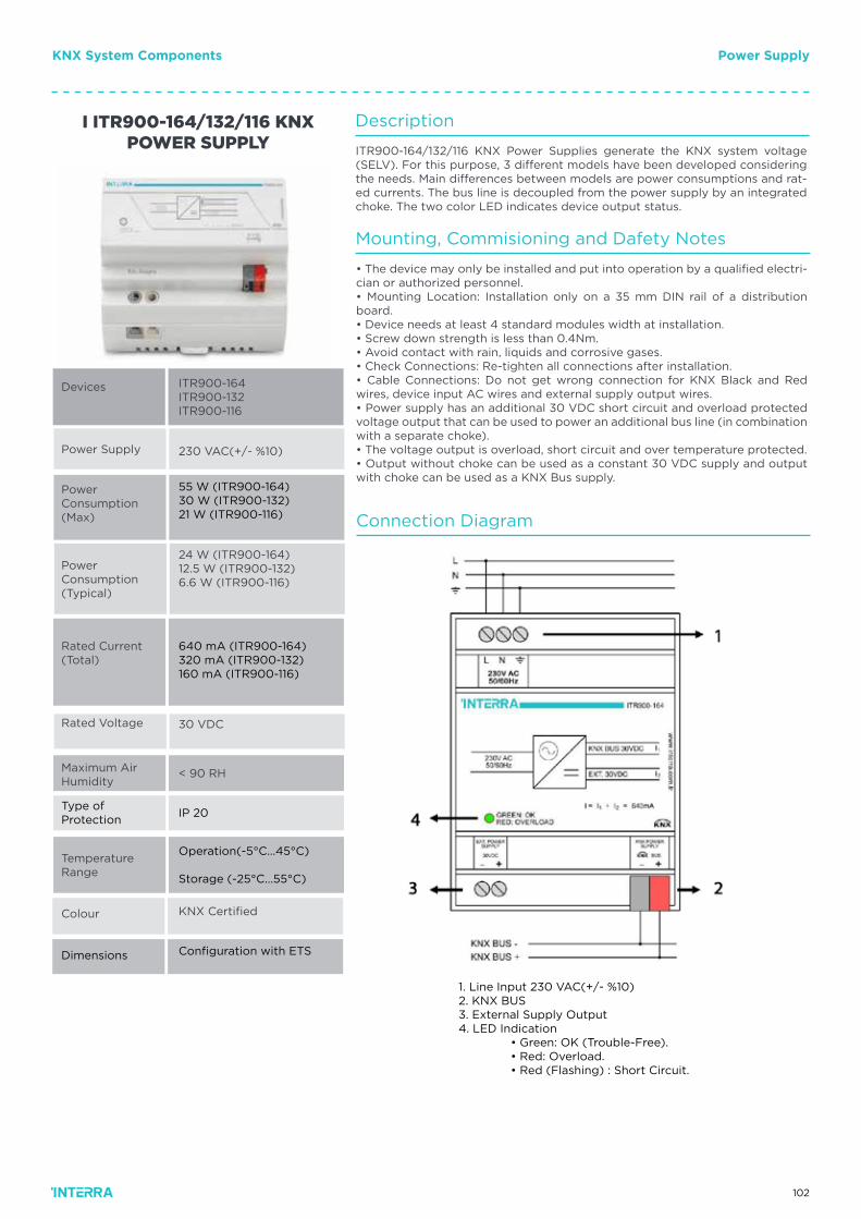
102
KNX System Components Power Supply
Description
Mounting, Commisioning and Dafety Notes
Connection Diagram
ITR900-164/132/116 KNX Power Supplies generate the KNX system voltage (SELV). For this purpose, 3 different models have been developed considering the needs. Main differences between models are power consumptions and rat-ed currents. The bus line is decoupled from the power supply by an integrated choke. The two color LED indicates device output status.
• The device may only be installed and put into operation by a qualified electri-cian or authorized personnel.• Mounting Location: Installation only on a 35 mm DIN rail of a distribution board.• Device needs at least 4 standard modules width at installation.• Screw down strength is less than 0.4Nm.• Avoid contact with rain, liquids and corrosive gases.• Check Connections: Re-tighten all connections after installation.• Cable Connections: Do not get wrong connection for KNX Black and Red wires, device input AC wires and external supply output wires.• Power supply has an additional 30 VDC short circuit and overload protected voltage output that can be used to power an additional bus line (in combination with a separate choke).• The voltage output is overload, short circuit and over temperature protected.• Output without choke can be used as a constant 30 VDC supply and output with choke can be used as a KNX Bus supply.
Power Supply
PowerConsumption (Max)
Power Consumption(Typical)
Rated Current (Total)
Colour
Rated Voltage
TemperatureRange
ITR900-164ITR900-132ITR900-116
Devices
230 VAC(+/- %10)
55 W (ITR900-164)30 W (ITR900-132)21 W (ITR900-116)
24 W (ITR900-164)12.5 W (ITR900-132)6.6 W (ITR900-116)
< 90 RH
KNX Certified
I ITR900-164/132/116 KNX POWER SUPPLY
30 VDC
Maximum AirHumidity
Type ofProtection
IP 20
Operation(-5°C...45°C)
Storage (-25°C...55°C)
640 mA (ITR900-164)320 mA (ITR900-132)160 mA (ITR900-116)
Dimensions Configuration with ETS
1. Line Input 230 VAC(+/- %10)2. KNX BUS3. External Supply Output4. LED Indication • Green: OK (Trouble-Free). • Red: Overload. • Red (Flashing) : Short Circuit.
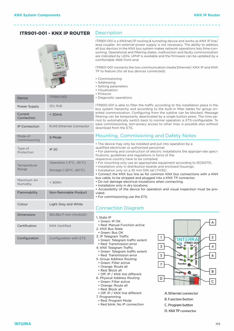
103
KNX System Components KNX IP Router
Mode ofCommisioning
Type of Protection
Temperature Range
ITR901-001
12V, PoE
< 20mA
RJ45 Ethernet Connector
90x36x71 mm (HxWxD)
< 90RH
Configuration with ETS
KNX Certified
ITR901-001 - KNX IP ROUTER
Operation (-5°C…45°C)
Storage (-20°C...60°C)
Maximum AirHumidity.
Flammability Non-flammable Product
Light Grey and White
S-Mode
IP 20
Device
Power Supply
Current Connection
IP Connection
Colour
Dimensions
Certification
Configuration
Description
ITR901-001 is a KNXnet/IP routing & tunneling device and works as KNX IP line/area coupler. An external power supply is not necessary. The ability to address all bus devices in the KNX bus system makes network operations less time-con-suming. Operational and filtering states, malfunction and faulty communication are indicated by LEDs. UPnP is available and the firmware can be updated by a comfortable Web front-end.
ITR901-001 connects the two communication media Ethernet/ KNX IP and KNX TP to feature (for all bus devices connected):
• Commissioning• Addressing• Setting parameters• Visualization• Protocol• Diagnostic operations
ITR900-001 is able to filter the traffic according to the installation place in the bus system hierarchy and according to the built-in filter tables for group ori-ented communication. Configuring from the subline can be blocked. Message filtering can be temporarily deactivated by a single button press. The time pe-riod to automatically switch back to normal operation is ETS-configurable. To ease commissioning, tem-porary access to other lines is possible also without download from the ETS.
Mounting, Commisioning and Dafety Notes
Connection Diagram
• The device may only be installed and put into operation by aqualified electrician or authorized personnel.• For planning and construction of electric installations the appropri-ate speci-fications, guidelines and regulations in force of therespective country have to be complied.• For mounting only use an appropriate equipment according to IEC60715.• Installation only in distribution boards and enclosed housings.• Installation only on a 35 mm DIN rail (TH35).• Connect the KNX bus line as for common KNX bus connections with a KNX bus cable, to be stripped and plugged into a KNX TP connector.• Do not damage electrical insulations when connecting.• Installation only in dry locations.• Accessibility of the device for operation and visual inspection must be pro-vided.• For commissioning use the ETS.
1. State IP • Green: IP OK • Red: Manual Function active2. KNX Bus State • Green: Bus OK3. IP Telegram Traffic • Green: Telegram traffic extent • Red: Transmission error4. KNX Telegram Traffic • Green: Telegram traffic extent • Red: Transmission error5. Group Address Routing • Green: Filter active • Orange: Route all • Red: Block all • Off: IP / KNX line different6. Physical Address Routing • Green: Filter active • Orange: Route all • Red: Block all • Off: IP / KNX line different7. Programming • Red: Program Mode • Red blink: No IP connection
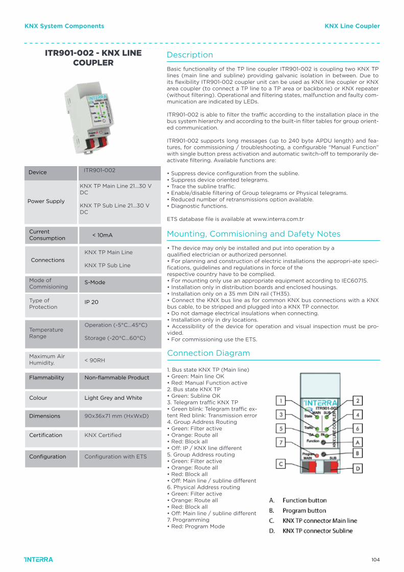
104
Description
Basic functionality of the TP line coupler ITR901-002 is coupling two KNX TP lines (main line and subline) providing galvanic isolation in between. Due to its flexibility ITR901-002 coupler unit can be used as KNX line coupler or KNX area coupler (to connect a TP line to a TP area or backbone) or KNX repeater (without filtering). Operational and filtering states, malfunction and faulty com-munication are indicated by LEDs.
ITR901-002 is able to filter the traffic according to the installation place in the bus system hierarchy and according to the built-in filter tables for group orient-ed communication.
ITR901-002 supports long messages (up to 240 byte APDU length) and fea-tures, for commissioning / troubleshooting, a configurable “Manual Function” with single button press activation and automatic switch-off to temporarily de-activate filtering. Available functions are:
• Suppress device configuration from the subline.• Suppress device oriented telegrams.• Trace the subline traffic.• Enable/disable filtering of Group telegrams or Physical telegrams.• Reduced number of retransmissions option available.• Diagnostic functions.
ETS database file is available at www.interra.com.tr
Mounting, Commisioning and Dafety Notes
Connection Diagram
• The device may only be installed and put into operation by aqualified electrician or authorized personnel.• For planning and construction of electric installations the appropri-ate speci-fications, guidelines and regulations in force of therespective country have to be complied.• For mounting only use an appropriate equipment according to IEC60715.• Installation only in distribution boards and enclosed housings.• Installation only on a 35 mm DIN rail (TH35).• Connect the KNX bus line as for common KNX bus connections with a KNX bus cable, to be stripped and plugged into a KNX TP connector.• Do not damage electrical insulations when connecting.• Installation only in dry locations.• Accessibility of the device for operation and visual inspection must be pro-vided.• For commissioning use the ETS.
1. Bus state KNX TP (Main line)• Green: Main line OK• Red: Manual Function active2. Bus state KNX TP• Green: Subline OK3. Telegram traffic KNX TP• Green blink: Telegram traffic ex-tent Red blink: Transmission error4. Group Address Routing• Green: Filter active• Orange: Route all• Red: Block all• Off: IP / KNX line different5. Group Address routing• Green: Filter active• Orange: Route all• Red: Block all• Off: Main line / subline different6. Physical Address routing• Green: Filter active• Orange: Route all• Red: Block all• Off: Main line / subline different7. Programming• Red: Program Mode
Mode ofCommisioning
Type of Protection
Temperature Range
ITR901-002
KNX TP Main Line 21…30 V DC
KNX TP Sub Line 21...30 V DC
< 10mA
KNX TP Main Line
KNX TP Sub Line
90x36x71 mm (HxWxD)
< 90RH
Configuration with ETS
KNX Certified
ITR901-002 - KNX LINE COUPLER
Operation (-5°C…45°C)
Storage (-20°C...60°C)
Maximum AirHumidity.
Flammability Non-flammable Product
Light Grey and White
S-Mode
IP 20
Device
Power Supply
Current Consumption
Connections
Colour
Dimensions
Certification
Configuration
KNX System Components KNX Line Coupler
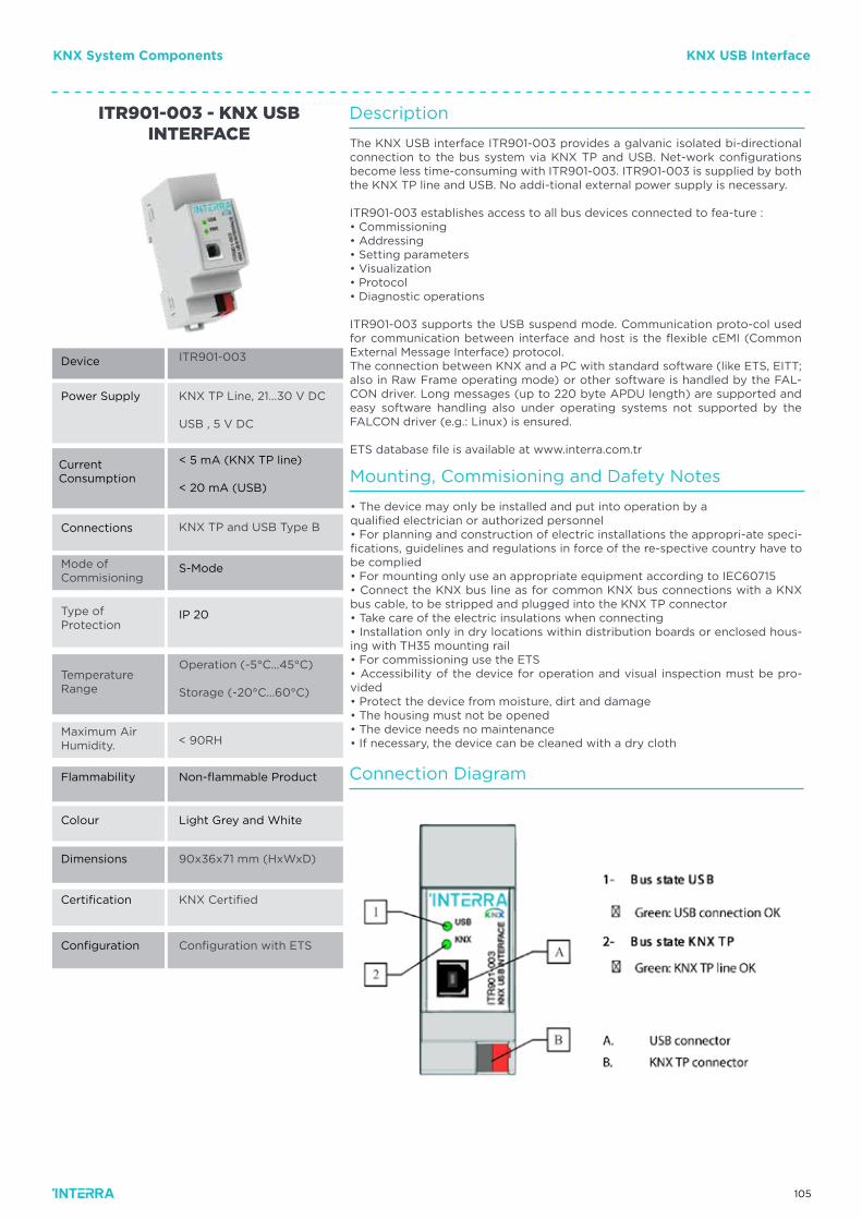
105
Mode ofCommisioning
Type of Protection
Temperature Range
ITR901-003
KNX TP Line, 21…30 V DC
USB , 5 V DC
< 5 mA (KNX TP line)
< 20 mA (USB)
KNX TP and USB Type B
90x36x71 mm (HxWxD)
< 90RH
Configuration with ETS
KNX Certified
ITR901-003 - KNX USB INTERFACE
Operation (-5°C…45°C)
Storage (-20°C...60°C)
Maximum AirHumidity.
Flammability Non-flammable Product
Light Grey and White
S-Mode
IP 20
Device
Power Supply
Current Consumption
Connections
Colour
Dimensions
Certification
Configuration
Description
The KNX USB interface ITR901-003 provides a galvanic isolated bi-directional connection to the bus system via KNX TP and USB. Net-work configurations become less time-consuming with ITR901-003. ITR901-003 is supplied by both the KNX TP line and USB. No addi-tional external power supply is necessary.
ITR901-003 establishes access to all bus devices connected to fea-ture :• Commissioning• Addressing• Setting parameters• Visualization• Protocol• Diagnostic operations
ITR901-003 supports the USB suspend mode. Communication proto-col used for communication between interface and host is the flexible cEMI (Common External Message Interface) protocol.The connection between KNX and a PC with standard software (like ETS, EITT; also in Raw Frame operating mode) or other software is handled by the FAL-CON driver. Long messages (up to 220 byte APDU length) are supported and easy software handling also under operating systems not supported by the FALCON driver (e.g.: Linux) is ensured.
ETS database file is available at www.interra.com.tr
Mounting, Commisioning and Dafety Notes
• The device may only be installed and put into operation by aqualified electrician or authorized personnel• For planning and construction of electric installations the appropri-ate speci-fications, guidelines and regulations in force of the re-spective country have to be complied• For mounting only use an appropriate equipment according to IEC60715• Connect the KNX bus line as for common KNX bus connections with a KNX bus cable, to be stripped and plugged into the KNX TP connector• Take care of the electric insulations when connecting• Installation only in dry locations within distribution boards or enclosed hous-ing with TH35 mounting rail• For commissioning use the ETS• Accessibility of the device for operation and visual inspection must be pro-vided• Protect the device from moisture, dirt and damage• The housing must not be opened• The device needs no maintenance• If necessary, the device can be cleaned with a dry cloth
Connection Diagram
KNX System Components KNX USB Interface
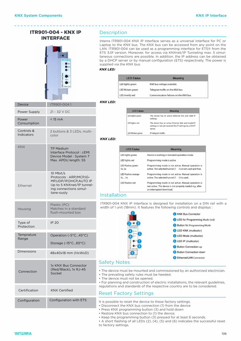
106
KNX
Ethernet
Housing
ITR901-004 1
21 ~ 32 V DC
< 15 mA
2 buttons & 3 LEDs, multi-color
ITR901-004 - KNX IP INTERFACE
Plastic (PC)Matches in a standard flush-mounted box
Button
Type ofProtection
Operation (-5°C...45°C)
Storage (-15°C...65°C)
IP 20
48x40x18 mm (HxWxD)
TP MediumInterface Protocol : cEMIDevice Model : System 7Max. APDU length: 55
10 Mbit/sProtocols : ARP,IMCP,IG-MP,UDP/IP,DHCP,AUTO IPUp to 5 KNXnet/IP tunnel-ing connections simul-tane-ously
Device
Power Supply
PowerConsumption
Controls & Indicators
Temprature Range
Dimensions
Certification
1x KNX Bus Connector (Red/Black), 1x RJ-45 Socket
Configuration with ETS
KNX Certified
Connection
Configuration
Description
Installation
Safety Notes
Reset Factory Settings
Interra ITR901-004 KNX IP Interface serves as a universal interface for PC or Laptop to the KNX bus. The KNX bus can be accessed from any point on the LAN. ITR901-004 can be used as a programming interface for ETS® from the ETS 3.0f version. Moreover, for access via KNXnet/IP Tunneling max. 5 simul-taneous connections are possible. In addition, the IP address can be obtained by a DHCP server or by manual configuration (ETS) respectively. The power is supplied via the KNX bus.
ITR901-004 KNX IP Interface is designed for installation on a DIN rail with a width of 1 unit (18mm). It features the following controls and displays :
• The device must be mounted and commissioned by an authorized electrician.• The prevailing safety rules must be heeded.• The device must not be opened.• For planning and construction of electric installations, the relevant guidelines, regulations and standards of the respective country are to be considered.
It is possible to reset the device to these factory settings.• Disconnect the KNX bus connection (1) from the device• Press KNX programming button (3) and hold down• Restore KNX bus connection to (1) the device.• Keep the programming button (3) pressed for at least 6 seconds.• A short flashing of all LEDs (2), (4), (5) and (6) indicates the successful reset to factory settings.
KNX LED:
KNX LED:
KNX LED:
KNX System Components KNX IP Interface
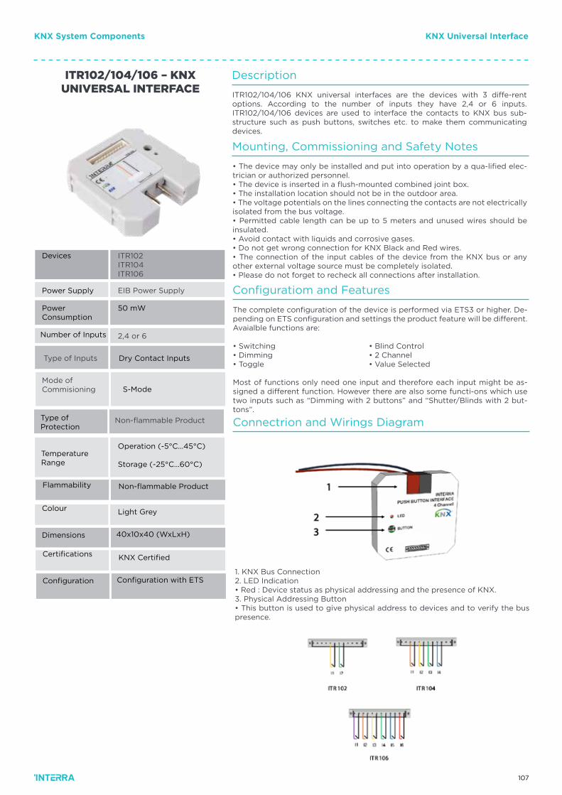
107
KNX System Components KNX Universal Interface
Description
Connectrion and Wirings Diagram
Mounting, Commissioning and Safety Notes
Configuratiom and Features
ITR102/104/106 KNX universal interfaces are the devices with 3 diffe-rent options. According to the number of inputs they have 2,4 or 6 inputs. ITR102/104/106 devices are used to interface the contacts to KNX bus sub-structure such as push buttons, switches etc. to make them communicating devices.
• The device may only be installed and put into operation by a qua-lified elec-trician or authorized personnel.• The device is inserted in a flush-mounted combined joint box.• The installation location should not be in the outdoor area.• The voltage potentials on the lines connecting the contacts are not electrically isolated from the bus voltage.• Permitted cable length can be up to 5 meters and unused wires should be insulated.• Avoid contact with liquids and corrosive gases.• Do not get wrong connection for KNX Black and Red wires.• The connection of the input cables of the device from the KNX bus or any other external voltage source must be completely isolated.• Please do not forget to recheck all connections after installation.
The complete configuration of the device is performed via ETS3 or higher. De-pending on ETS configuration and settings the product feature will be different. Avaialble functions are:
• Switching • Blind Control• Dimming • 2 Channel• Toggle • Value Selected
Most of functions only need one input and therefore each input might be as-signed a different function. However there are also some functi-ons which use two inputs such as “Dimming with 2 buttons” and “Shutter/Blinds with 2 but-tons”.
Type of Inputs
Mode of Commisioning
ITR102ITR104ITR106
EIB Power Supply
50 mW
2,4 or 6
ITR102/104/106 – KNX UNIVERSAL INTERFACE
Non-flammable Product
Button
Button
TemperatureRange
Non-flammable Product
Operation (-5°C...45°C)
Storage (-25°C...60°C)
KNX Certified
Light Grey
Dry Contact Inputs
S-Mode
Devices
Power Supply
PowerConsumption
Number of Inputs
Flammability
Certifications
Colour
Configuration with ETS
40x10x40 (WxLxH)
Configuration
Dimensions
Type of Protection
1. KNX Bus Connection2. LED Indication• Red : Device status as physical addressing and the presence of KNX.3. Physical Addressing Button• This button is used to give physical address to devices and to verify the bus presence.
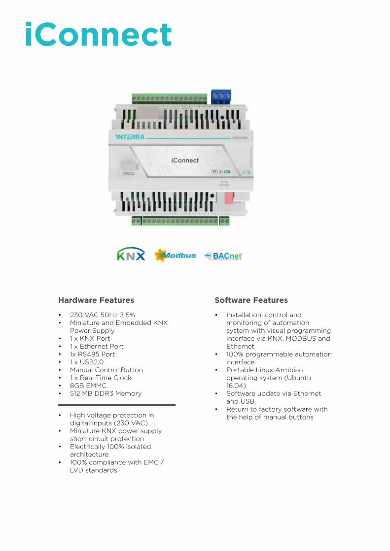
108
Hardware Features
• 230 VAC 50Hz ± 5%• Miniature and Embedded KNX
Power Supply• 1 x KNX Port• 1 x Ethernet Port• 1x RS485 Port• 1 x USB2.0• Manual Control Button• 1 x Real Time Clock• 8GB EMMC• 512 MB DDR3 Memory
• Installation, control and monitoring of automation system with visual programming interface via KNX, MODBUS and Ethernet
• 100% programmable automation interface
• Portable Linux Armbian operating system (Ubuntu 16.04)
• Software update via Ethernet and USB
• Return to factory software with the help of manual buttons• High voltage protection in
digital inputs (230 VAC)• Miniature KNX power supply
short circuit protection• Electrically 100% isolated
architecture• 100% compliance with EMC /
LVD standards
Software Features
iConnect
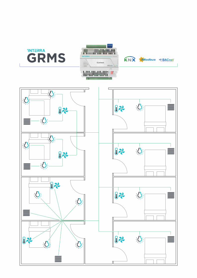
109

110
iConnectwiring diagram
110 - 230
Digital Inputs
GRMS Hotel Solutions iConnect
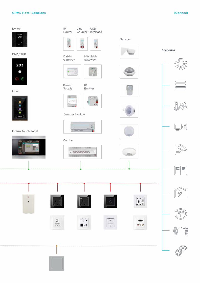
111
Iswitch
Imini
Interra Touch Panel
DND/MUR
Sensors
Scenerios
Combo
Dimmer Module
PowerSupply
IREmitter
DaikinGateway
MitsubishiGateway
IPRouter
LineCoupler
USBInterface
GRMS Hotel Solutions iConnect
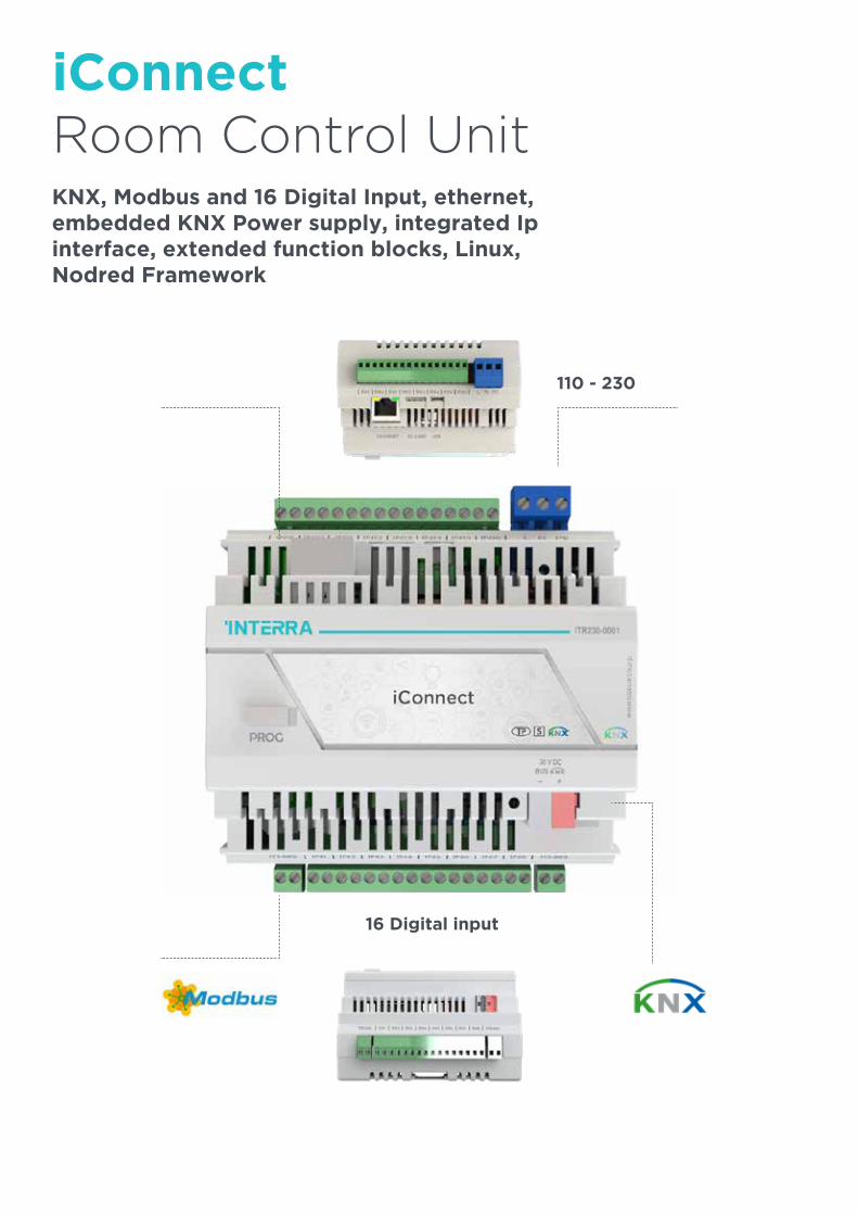
112
KNX, Modbus and 16 Digital Input, ethernet, embedded KNX Power supply, integrated Ip interface, extended function blocks, Linux, Nodred Framework
16 Digital input
110 - 230
iConnectRoom Control Unit

113
KNX, direct to TCP network, Modbus, GRMS, DND/MUR Service logics, GRMS server application, scenarios, room modes, Access control system integration, many options for digital outputs, mobile access to the room, integrations Fidelio, Salto, Assa Abloy, etc.
Smart Solution

114
Lightingairconditioning
Economy
Check-in I Check-out
Curtain / Blind Control
ReceptionHousekeeping
Comfort mode
New Hotels of the Future INTERRA
Meets iConnect Technology
You can allow many activities such as SPA, Taxi, cleaning, sports, concerts, meals etc. to reach the room guest. You can contribute to a unique experience and to the image of the
facility by providing this in an interactive way.
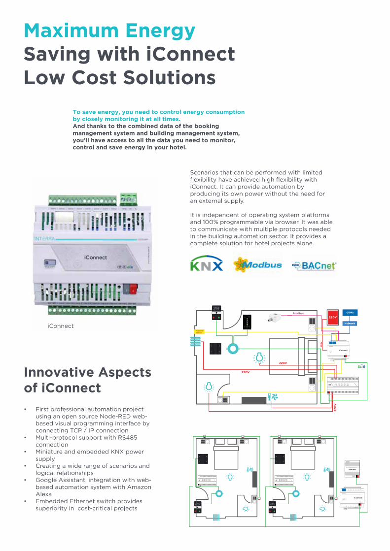
115
iConnect
iConnect
Maximum EnergySaving with iConnectLow Cost Solutions
To save energy, you need to control energy consumption by closely monitoring it at all times.And thanks to the combined data of the booking management system and building management system, you’ll have access to all the data you need to monitor, control and save energy in your hotel.
Scenarios that can be performed with limited flexibility have achieved high flexibility with iConnect. It can provide automation by producing its own power without the need for an external supply.
It is independent of operating system platforms and 100% programmable via browser. It was able to communicate with multiple protocols needed in the building automation sector. It provides a complete solution for hotel projects alone.
• First professional automation project using an open source Node-RED web-based visual programming interface by connecting TCP / IP connection
• Multi-protocol support with RS485 connection
• Miniature and embedded KNX power supply
• Creating a wide range of scenarios and logical relationships
• Google Assistant, integration with web-based automation system with Amazon Alexa
• Embedded Ethernet switch provides superiority in cost-critical projects
Innovative Aspects of iConnect
iConnect
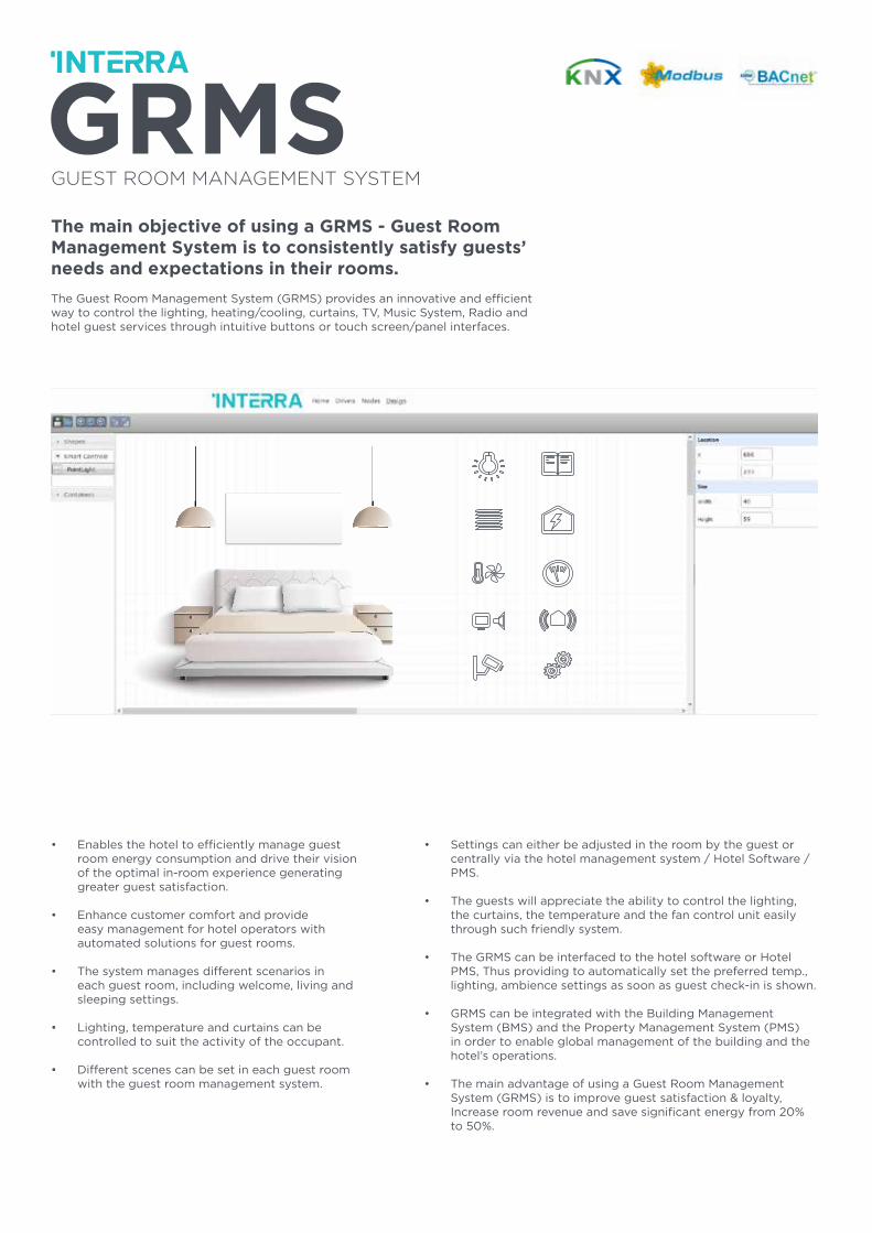
116
The main objective of using a GRMS - Guest Room Management System is to consistently satisfy guests’ needs and expectations in their rooms.
The Guest Room Management System (GRMS) provides an innovative and efficient way to control the lighting, heating/cooling, curtains, TV, Music System, Radio and hotel guest services through intuitive buttons or touch screen/panel interfaces.
GUEST ROOM MANAGEMENT SYSTEM
• Enables the hotel to efficiently manage guest room energy consumption and drive their vision of the optimal in-room experience generating greater guest satisfaction.
• Enhance customer comfort and provide easy management for hotel operators with automated solutions for guest rooms.
• The system manages different scenarios in each guest room, including welcome, living and sleeping settings.
• Lighting, temperature and curtains can be controlled to suit the activity of the occupant.
• Different scenes can be set in each guest room with the guest room management system.
• Settings can either be adjusted in the room by the guest or centrally via the hotel management system / Hotel Software / PMS.
• The guests will appreciate the ability to control the lighting, the curtains, the temperature and the fan control unit easily through such friendly system.
• The GRMS can be interfaced to the hotel software or Hotel PMS, Thus providing to automatically set the preferred temp., lighting, ambience settings as soon as guest check-in is shown.
• GRMS can be integrated with the Building Management System (BMS) and the Property Management System (PMS) in order to enable global management of the building and the hotel’s operations.
• The main advantage of using a Guest Room Management System (GRMS) is to improve guest satisfaction & loyalty, Increase room revenue and save significant energy from 20% to 50%.
GRMS Hotel Solutions iConnect
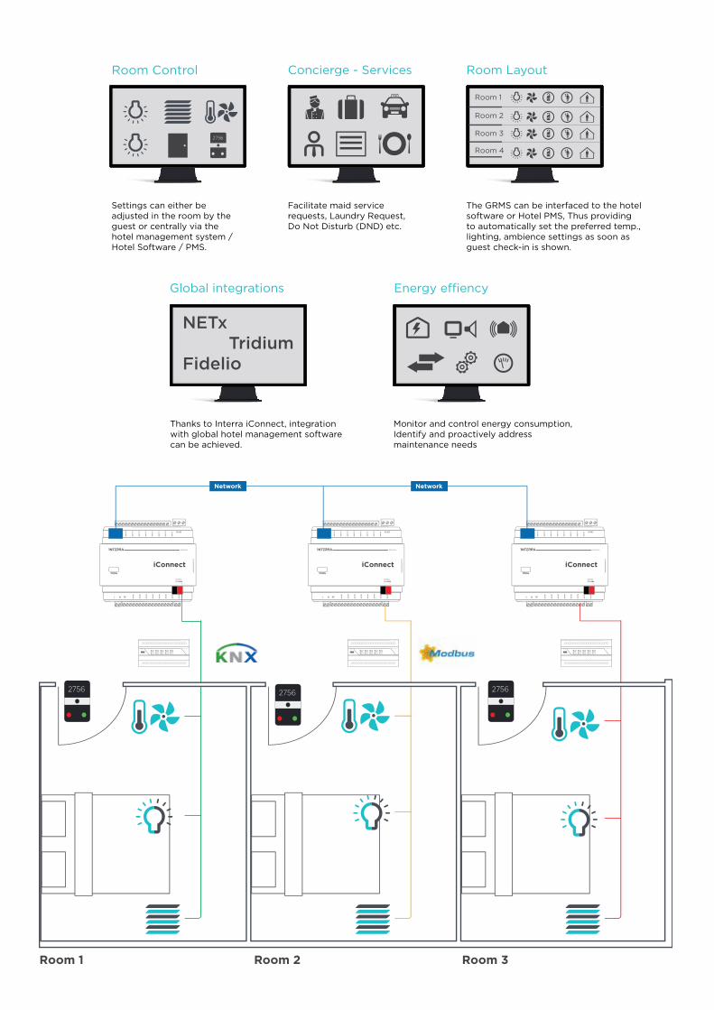
117
iConnect iConnect iConnect
Room 1 Room 2 Room 3
Concierge - Services
Global integrations Energy e�ency
NETx TridiumFidelio
Room Control Room Layout
Room 1
Room 2
Room 3
Room 4
Settings can either be adjusted in the room by the guest or centrally via the hotel management system / Hotel Software / PMS.
Facilitate maid service requests, Laundry Request, Do Not Disturb (DND) etc.
Thanks to Interra iConnect, integration with global hotel management software can be achieved.
Monitor and control energy consumption,Identify and proactively addressmaintenance needs
The GRMS can be interfaced to the hotel software or Hotel PMS, Thus providing to automatically set the preferred temp., lighting, ambience settings as soon as guest check-in is shown.
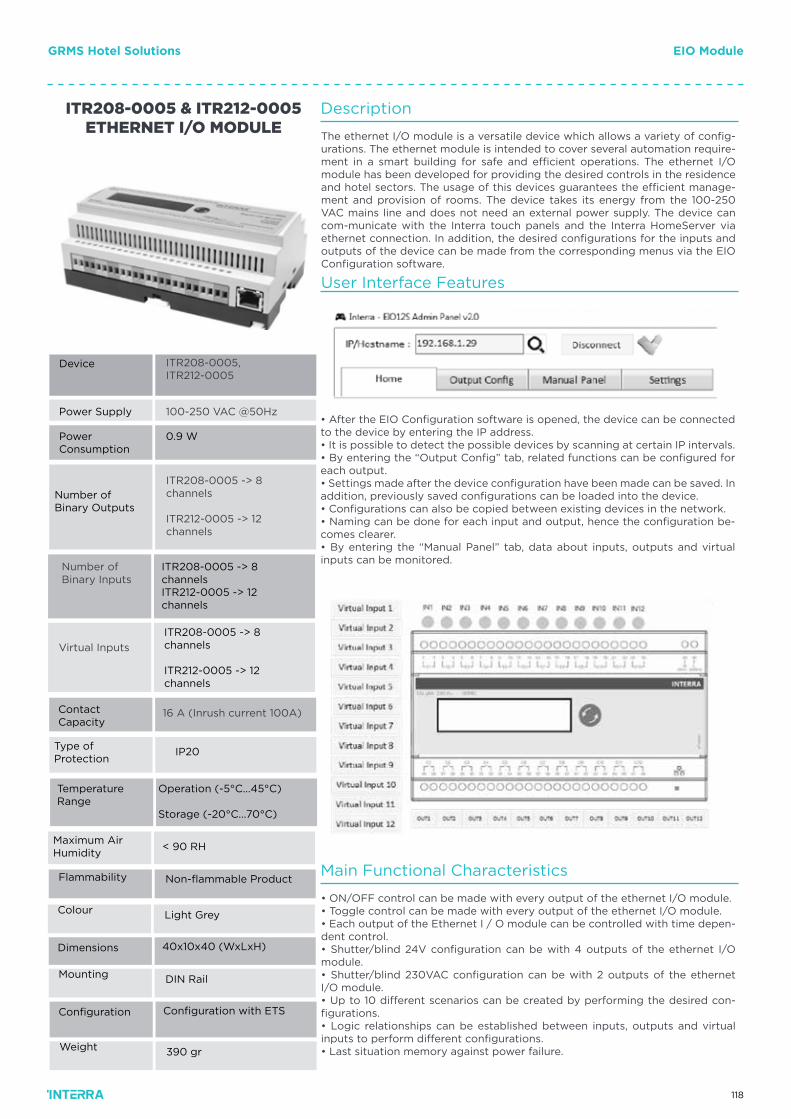
118
Number of Binary Inputs
Virtual Inputs
ITR208-0005, ITR212-0005
100-250 VAC @50Hz
0.9 W
ITR208-0005 -> 8 channels
ITR212-0005 -> 12 channels
ITR208-0005 & ITR212-0005ETHERNET I/O MODULE
16 A (Inrush current 100A)
Button
Button
Type ofProtection
Non-flammable Product
IP20
DIN Rail
390 gr
Light Grey
ITR208-0005 -> 8 channelsITR212-0005 -> 12 channels
ITR208-0005 -> 8 channels
ITR212-0005 -> 12 channels
Device
Power Supply
PowerConsumption
Number of Binary Outputs
Flammability
Mounting
Weight
Colour
Configuration with ETS
40x10x40 (WxLxH)
Configuration
Dimensions
Contact Capacity
Temperature Range
Operation (-5°C...45°C)
Storage (-20°C...70°C)
Maximum AirHumidity
< 90 RH
Description
Main Functional Characteristics
User Interface Features
The ethernet I/O module is a versatile device which allows a variety of config-urations. The ethernet module is intended to cover several automation require-ment in a smart building for safe and efficient operations. The ethernet I/O module has been developed for providing the desired controls in the residence and hotel sectors. The usage of this devices guarantees the efficient manage-ment and provision of rooms. The device takes its energy from the 100-250 VAC mains line and does not need an external power supply. The device can com-municate with the Interra touch panels and the Interra HomeServer via ethernet connection. In addition, the desired configurations for the inputs and outputs of the device can be made from the corresponding menus via the EIO Configuration software.
• ON/OFF control can be made with every output of the ethernet I/O module.• Toggle control can be made with every output of the ethernet I/O module.• Each output of the Ethernet I / O module can be controlled with time depen-dent control.• Shutter/blind 24V configuration can be with 4 outputs of the ethernet I/O module.• Shutter/blind 230VAC configuration can be with 2 outputs of the ethernet I/O module.• Up to 10 different scenarios can be created by performing the desired con-figurations.• Logic relationships can be established between inputs, outputs and virtual inputs to perform different configurations.• Last situation memory against power failure.
• After the EIO Configuration software is opened, the device can be connected to the device by entering the IP address.• It is possible to detect the possible devices by scanning at certain IP intervals.• By entering the “Output Config” tab, related functions can be configured for each output.• Settings made after the device configuration have been made can be saved. In addition, previously saved configurations can be loaded into the device.• Configurations can also be copied between existing devices in the network.• Naming can be done for each input and output, hence the configuration be-comes clearer.• By entering the “Manual Panel” tab, data about inputs, outputs and virtual inputs can be monitored.
GRMS Hotel Solutions EIO Module
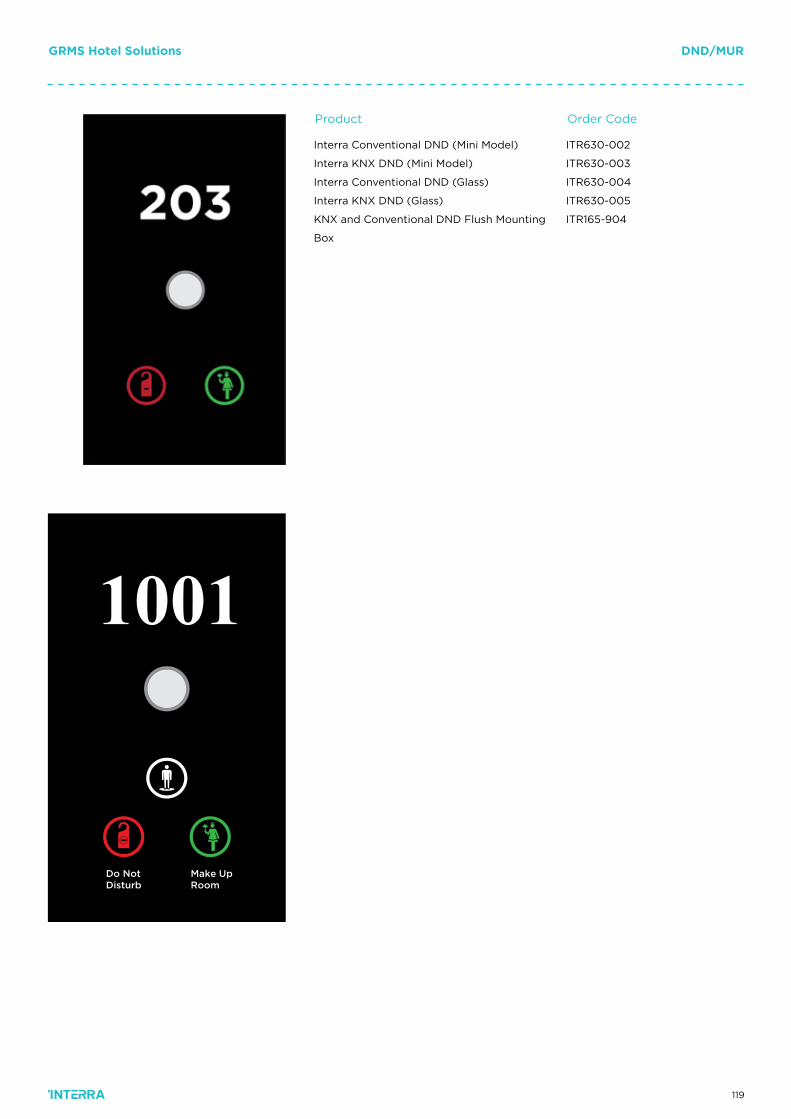
119
GRMS Hotel Solutions DND/MUR
ITR630-002
ITR630-003
ITR630-004
ITR630-005
ITR165-904
Interra Conventional DND (Mini Model)
Interra KNX DND (Mini Model)
Interra Conventional DND (Glass)
Interra KNX DND (Glass)
KNX and Conventional DND Flush Mounting
Box
Order CodeProduct
Do NotDisturb
Make UpRoom
1001
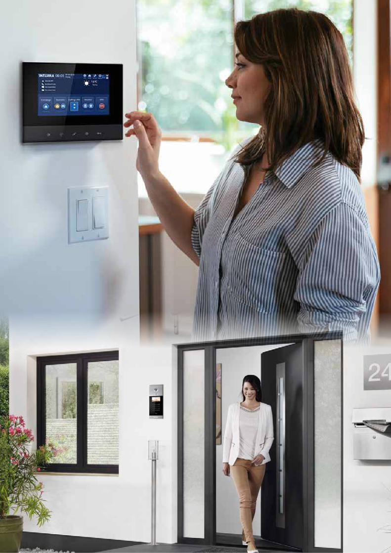
120
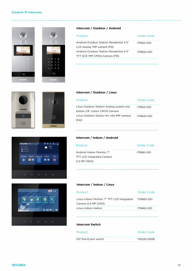
121
iControl IP Intercom
Order CodeProduct
ITR651-001
ITR650-001
Android Outdoor Station Residential 4.3”
LCD display 1MP camera IP55
Android Outdoor Station Residential 4.3”
TFT SCD 1MP CMOS Camera IP55
Intercom / Outdoor / Android
Order CodeProduct
ITR641-001
ITR640-001
Linux Outdoor Station Analog system one
button 1/4” colour CMOS Camera
Linux Outdoor Station for villa 1MP camera
IP40
Intercom / Outdoor / Linux
Order CodeProduct
ITR661-001Android Indoor Monitor 7”
TFT LCD Integrated Camero
0.3 MP CMOS
Intercom / Indoor / Android
Order CodeProduct
ITR660-001
ITR662-001
Linux Indoor Monitor 7” TFT LCD Integrated
Camero 0.3 MP CMOS
Linux indoor station
Intercom / Indoor / Linux
Order CodeProduct
ITR220-000812V Poe 8 port switch
Intercom Switch
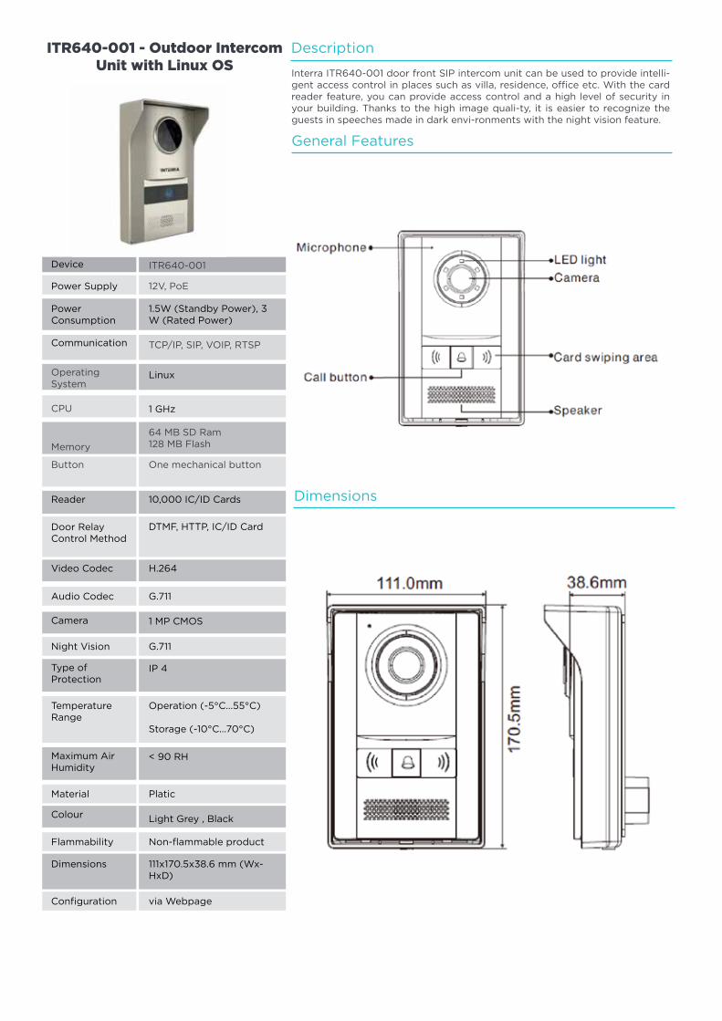
122
Description
General Features
Dimensions
Interra ITR640-001 door front SIP intercom unit can be used to provide intelli-gent access control in places such as villa, residence, office etc. With the card reader feature, you can provide access control and a high level of security in your building. Thanks to the high image quali-ty, it is easier to recognize the guests in speeches made in dark envi-ronments with the night vision feature.
Operating System
CPU
Memory
ITR640-001
12V, PoE
1.5W (Standby Power), 3 W (Rated Power)
TCP/IP, SIP, VOIP, RTSP
One mechanical button
ITR640-001 - Outdoor Intercom Unit with Linux OS
64 MB SD Ram128 MB Flash
Button
Reader
Video Codec
Camera
Colour
Dimensions
10,000 IC/ID Cards
H.264
1 MP CMOS
Light Grey , Black
111x170.5x38.6 mm (Wx-HxD)
DTMF, HTTP, IC/ID Card
G.711
Platic
via Webpage
Non-flammable product
G.711
Linux
1 GHz
Device
Power Supply
PowerConsumption
Communication
Door Relay Control Method
Audio Codec
Material
Configuration
Flammability
Night Vision
Type ofProtection
Maximum AirHumidity
IP 4
< 90 RH
Operation (-5°C...55°C)
Storage (-10°C...70°C)
TemperatureRange
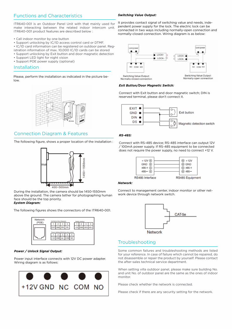
123
Functions and Characteristics
Troubleshooting
Installation
Connection Diagram & Features
ITR640-001 is an Outdoor Panel Unit with that mainly used for make interacting between the related indoor intercom unit. ITR640-001 product features are described below :
• Call indoor monitor by one button• Support unlocking by IC/ID access control card or DTMF.• IC/ID card information can be registered on outdoor panel. Reg-istration information of max. 10,000 IC/ID cards can be stored• Support unlocking by Exit button and door magnetic detection• Support LED light for night vision• Support POE power supply (optional)
Some common failures and troubleshooting methods are listed for your reference. In case of failure which cannot be repaired, do not disassemble or repair the product by yourself. Please contact the after-sales technical service department.
When setting villa outdoor panel, please make sure building No. and unit No. of outdoor panel are the same as the ones of indoor monitor.
Please check whether the network is connected.
Please check if there are any security setting for the network.
The following figure, shows a proper location of the installation :
During the installation, the camera should be 1450-1550mm above the ground. The camera tether for photographing human face should be the top priority.System Diagram:
The following figures shows the connectors of the ITR640-001.
Power / Unlock Signal Output:
Power input interface connects with 12V DC power adapter. Wiring diagram is as follows:
Switching Value Output:
It provides contact signal of switching value and needs, inde-pendent power supply for the lock. The electric lock can be connected in two ways including normally-open connection and normally-closed connection. Wiring diagram is as below:
RS-485:
Connect with RS-485 device; RS-485 interface can output 12V / 100mA power supply. If RS-485 equipment to be connected does not require the power supply, no need to connect +12 V.
Exit Button/Door Magnetic Switch:
Connect with Exit button and door magnetic switch; DIN is reserved terminal, please don’t connect it.
Network:
Connect to management center, indoor monitor or other net-work device through network switch.
Please, perform the installation as indicated in the picture be-low.
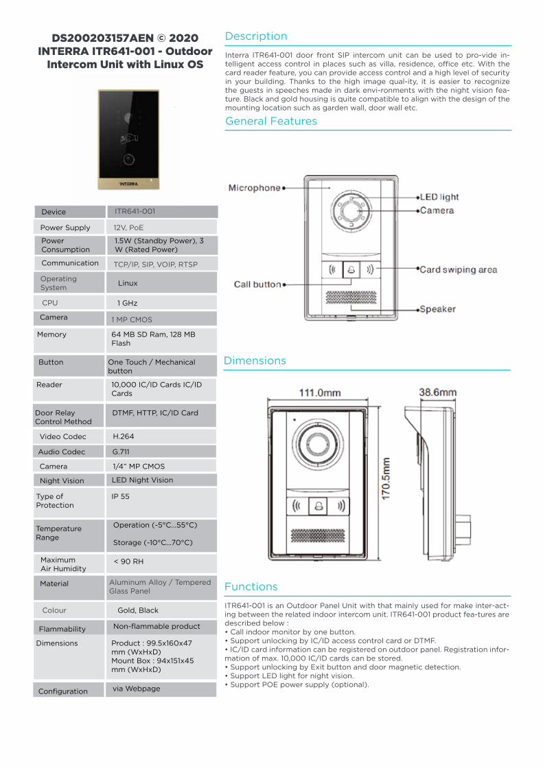
124
Operating System
CPU
ITR641-001
12V, PoE
1.5W (Standby Power), 3 W (Rated Power)
TCP/IP, SIP, VOIP, RTSP
DS200203157AEN © 2020 INTERRA ITR641-001 - Outdoor
Intercom Unit with Linux OS
1 MP CMOS
Button
Memory
DTMF, HTTP, IC/ID Card
Operation (-5°C...55°C)
Storage (-10°C...70°C)
64 MB SD Ram, 128 MB Flash
1/4” MP CMOS
IP 55
Product : 99.5x160x47 mm (WxHxD)Mount Box : 94x151x45 mm (WxHxD)
H.264
< 90 RH
Linux
1 GHz
Device
Power Supply
PowerConsumption
Communication
Door Relay Control Method
Temperature Range
Camera
Type of Protection
Dimensions
Video Codec
Maximum Air Humidity
LED Night Vision
G.711
Non-flammable product
via Webpage
Night Vision
Audio Codec
Flammability
Configuration
Camera
Button One Touch / Mechanical button
Reader 10,000 IC/ID Cards IC/ID Cards
Colour
Aluminum Alloy / Tempered Glass Panel
Gold, Black
Material
Description
Functions
Dimensions
General Features
Interra ITR641-001 door front SIP intercom unit can be used to pro-vide in-telligent access control in places such as villa, residence, office etc. With the card reader feature, you can provide access control and a high level of security in your building. Thanks to the high image qual-ity, it is easier to recognize the guests in speeches made in dark envi-ronments with the night vision fea-ture. Black and gold housing is quite compatible to align with the design of the mounting location such as garden wall, door wall etc.
ITR641-001 is an Outdoor Panel Unit with that mainly used for make inter-act-ing between the related indoor intercom unit. ITR641-001 product fea-tures are described below :• Call indoor monitor by one button.• Support unlocking by IC/ID access control card or DTMF.• IC/ID card information can be registered on outdoor panel. Registration infor-mation of max. 10,000 IC/ID cards can be stored.• Support unlocking by Exit button and door magnetic detection.• Support LED light for night vision.• Support POE power supply (optional).
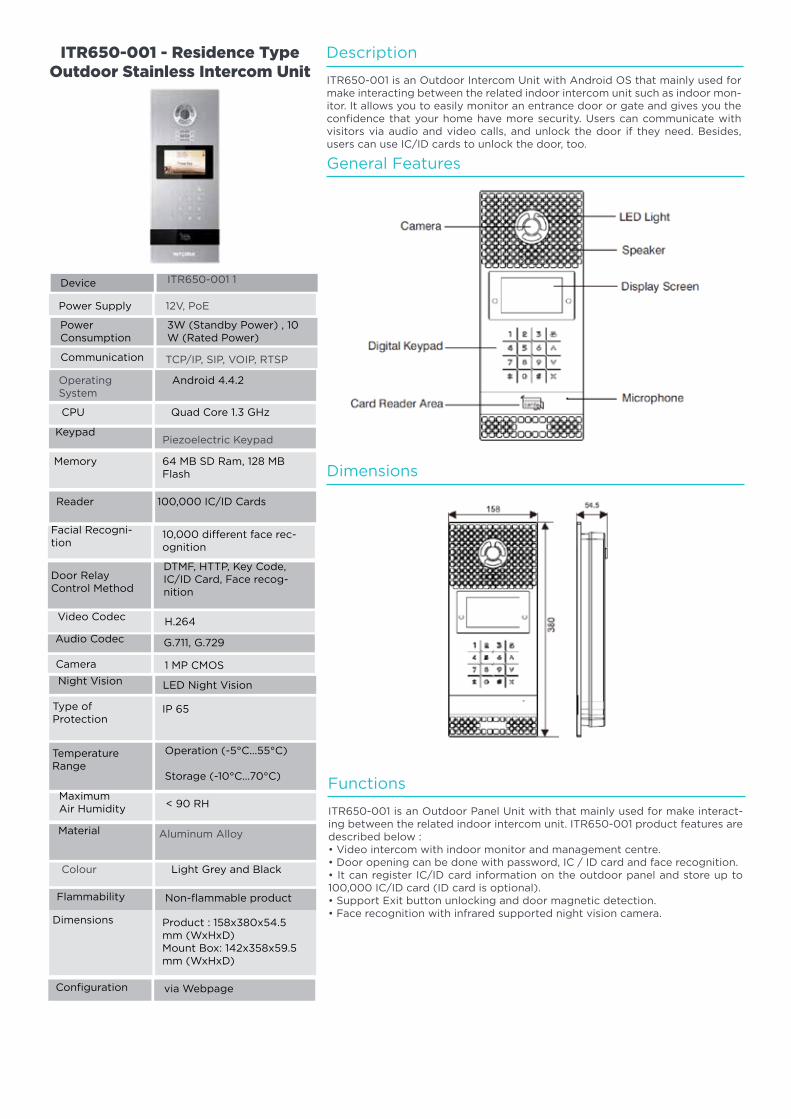
125
Operating System
ITR650-001 1
12V, PoE
3W (Standby Power) , 10 W (Rated Power)
TCP/IP, SIP, VOIP, RTSP
ITR650-001 - Residence Type Outdoor Stainless Intercom Unit
Piezoelectric Keypad
Memory
DTMF, HTTP, Key Code, IC/ID Card, Face recog-nition
Operation (-5°C...55°C)
Storage (-10°C...70°C)
64 MB SD Ram, 128 MB Flash
1 MP CMOS
IP 65
Product : 158x380x54.5 mm (WxHxD)Mount Box: 142x358x59.5 mm (WxHxD)
H.264
< 90 RH
Android 4.4.2
Quad Core 1.3 GHz
Device
Power Supply
PowerConsumption
Communication
Door Relay Control Method
Temperature Range
Type of Protection
Dimensions
Video Codec
Maximum Air Humidity
LED Night Vision
G.711, G.729
Non-flammable product
via Webpage
Night Vision
Audio Codec
Camera
Flammability
Configuration
Reader 100,000 IC/ID Cards
10,000 different face rec-ognition
Colour
Aluminum Alloy
Light Grey and Black
Material
CPU
Keypad
Facial Recogni-tion
Description
General Features
Dimensions
ITR650-001 is an Outdoor Intercom Unit with Android OS that mainly used for make interacting between the related indoor intercom unit such as indoor mon-itor. It allows you to easily monitor an entrance door or gate and gives you the confidence that your home have more security. Users can communicate with visitors via audio and video calls, and unlock the door if they need. Besides, users can use IC/ID cards to unlock the door, too.
Functions
ITR650-001 is an Outdoor Panel Unit with that mainly used for make interact-ing between the related indoor intercom unit. ITR650-001 product features are described below :• Video intercom with indoor monitor and management centre.• Door opening can be done with password, IC / ID card and face recognition.• It can register IC/ID card information on the outdoor panel and store up to 100,000 IC/ID card (ID card is optional).• Support Exit button unlocking and door magnetic detection.• Face recognition with infrared supported night vision camera.
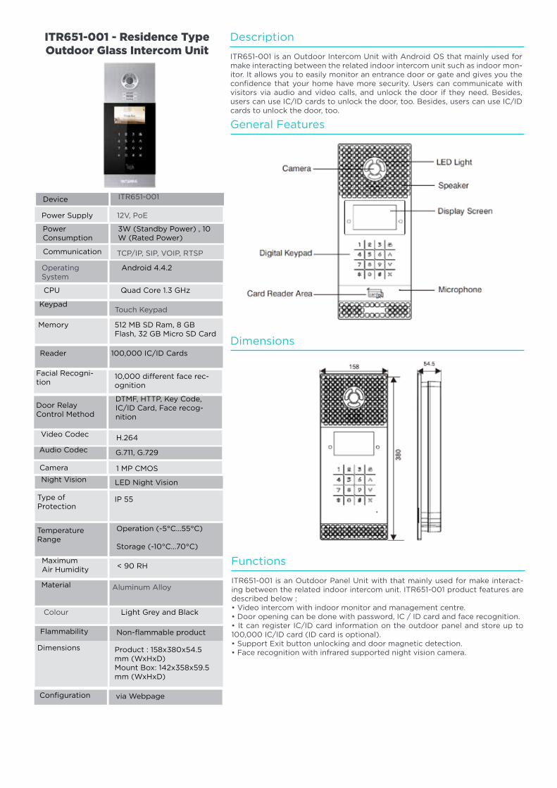
126
Operating System
ITR651-001
12V, PoE
3W (Standby Power) , 10 W (Rated Power)
TCP/IP, SIP, VOIP, RTSP
ITR651-001 - Residence Type Outdoor Glass Intercom Unit
Touch Keypad
Memory
DTMF, HTTP, Key Code, IC/ID Card, Face recog-nition
Operation (-5°C...55°C)
Storage (-10°C...70°C)
512 MB SD Ram, 8 GB Flash, 32 GB Micro SD Card
1 MP CMOS
IP 55
Product : 158x380x54.5 mm (WxHxD)Mount Box: 142x358x59.5 mm (WxHxD)
H.264
< 90 RH
Android 4.4.2
Quad Core 1.3 GHz
Device
Power Supply
PowerConsumption
Communication
Door Relay Control Method
Temperature Range
Type of Protection
Dimensions
Video Codec
Maximum Air Humidity
LED Night Vision
G.711, G.729
Non-flammable product
via Webpage
Night Vision
Audio Codec
Camera
Flammability
Configuration
Reader 100,000 IC/ID Cards
10,000 different face rec-ognition
Colour
Aluminum Alloy
Light Grey and Black
Material
CPU
Keypad
Facial Recogni-tion
Description
General Features
Dimensions
ITR651-001 is an Outdoor Intercom Unit with Android OS that mainly used for make interacting between the related indoor intercom unit such as indoor mon-itor. It allows you to easily monitor an entrance door or gate and gives you the confidence that your home have more security. Users can communicate with visitors via audio and video calls, and unlock the door if they need. Besides, users can use IC/ID cards to unlock the door, too. Besides, users can use IC/ID cards to unlock the door, too.
Functions
ITR651-001 is an Outdoor Panel Unit with that mainly used for make interact-ing between the related indoor intercom unit. ITR651-001 product features are described below :• Video intercom with indoor monitor and management centre.• Door opening can be done with password, IC / ID card and face recognition.• It can register IC/ID card information on the outdoor panel and store up to 100,000 IC/ID card (ID card is optional).• Support Exit button unlocking and door magnetic detection.• Face recognition with infrared supported night vision camera.
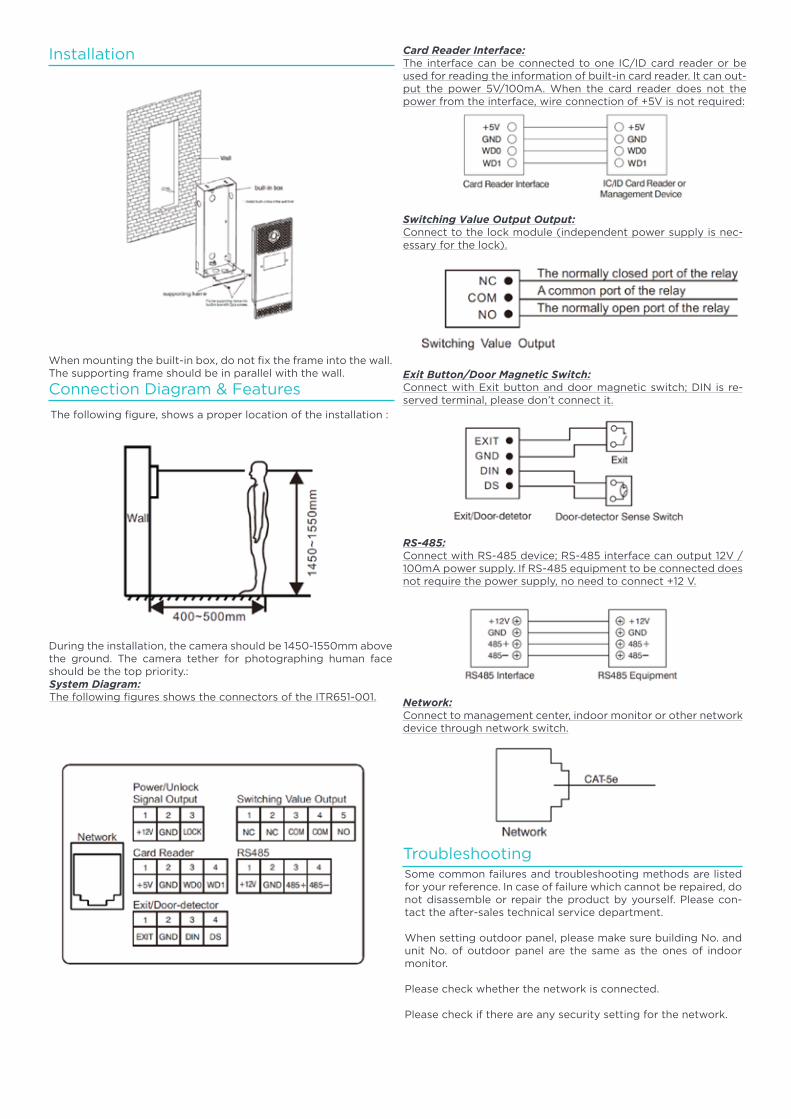
127
Installation
When mounting the built-in box, do not fix the frame into the wall. The supporting frame should be in parallel with the wall.
Connection Diagram & Features
The following figure, shows a proper location of the installation :
During the installation, the camera should be 1450-1550mm above the ground. The camera tether for photographing human face should be the top priority.:System Diagram:The following figures shows the connectors of the ITR651-001.
Card Reader Interface:The interface can be connected to one IC/ID card reader or be used for reading the information of built-in card reader. It can out-put the power 5V/100mA. When the card reader does not the power from the interface, wire connection of +5V is not required:
Switching Value Output Output:Connect to the lock module (independent power supply is nec-essary for the lock).
Exit Button/Door Magnetic Switch:Connect with Exit button and door magnetic switch; DIN is re-served terminal, please don’t connect it.
RS-485:Connect with RS-485 device; RS-485 interface can output 12V / 100mA power supply. If RS-485 equipment to be connected does not require the power supply, no need to connect +12 V.
TroubleshootingSome common failures and troubleshooting methods are listed for your reference. In case of failure which cannot be repaired, do not disassemble or repair the product by yourself. Please con-tact the after-sales technical service department.
When setting outdoor panel, please make sure building No. and unit No. of outdoor panel are the same as the ones of indoor monitor.
Please check whether the network is connected.
Please check if there are any security setting for the network.
Network:Connect to management center, indoor monitor or other network device through network switch.
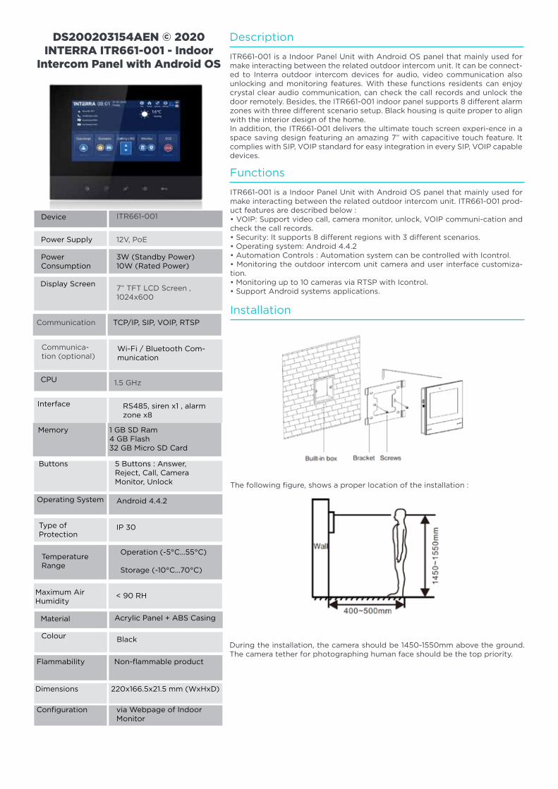
128
Communication
Communica-tion (optional)
ITR661-001
12V, PoE
3W (Standby Power)10W (Rated Power)
7” TFT LCD Screen , 1024x600
DS200203154AEN © 2020 INTERRA ITR661-001 - Indoor
Intercom Panel with Android OS
1.5 GHz
Button
Interface
Android 4.4.2
RS485, siren x1 , alarm zone x8
< 90 RH
Black
220x166.5x21.5 mm (WxHxD)
IP 30
TCP/IP, SIP, VOIP, RTSP
Wi-Fi / Bluetooth Com-munication
Device
Power Supply
PowerConsumption
Display Screen
Operating System
Maximum AirHumidity
Colour
Type ofProtection
Acrylic Panel + ABS Casing
Non-flammable productFlammability
Dimensions
Configuration via Webpage of Indoor Monitor
Operation (-5°C...55°C)
Storage (-10°C...70°C)
Material
TemperatureRange
CPU
Memory 1 GB SD Ram4 GB Flash32 GB Micro SD Card
Buttons 5 Buttons : Answer, Reject, Call, Camera Monitor, Unlock
Description
Functions
Installation
ITR661-001 is a Indoor Panel Unit with Android OS panel that mainly used for make interacting between the related outdoor intercom unit. It can be connect-ed to Interra outdoor intercom devices for audio, video communication also unlocking and monitoring features. With these functions residents can enjoy crystal clear audio communication, can check the call records and unlock the door remotely. Besides, the ITR661-001 indoor panel supports 8 different alarm zones with three different scenario setup. Black housing is quite proper to align with the interior design of the home.In addition, the ITR661-001 delivers the ultimate touch screen experi-ence in a space saving design featuring an amazing 7” with capacitive touch feature. It complies with SIP, VOIP standard for easy integration in every SIP, VOIP capable devices.
ITR661-001 is a Indoor Panel Unit with Android OS panel that mainly used for make interacting between the related outdoor intercom unit. ITR661-001 prod-uct features are described below :• VOIP: Support video call, camera monitor, unlock, VOIP communi-cation and check the call records.• Security: It supports 8 different regions with 3 different scenarios.• Operating system: Android 4.4.2• Automation Controls : Automation system can be controlled with Icontrol.• Monitoring the outdoor intercom unit camera and user interface customiza-tion.• Monitoring up to 10 cameras via RTSP with Icontrol.• Support Android systems applications.
The following figure, shows a proper location of the installation :
During the installation, the camera should be 1450-1550mm above the ground. The camera tether for photographing human face should be the top priority.
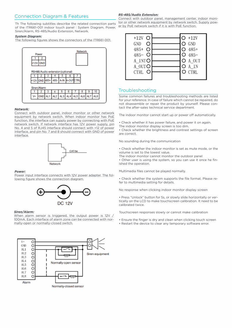
129
Connection Diagram & Features
Th The following subtitles describe the related connection parts of the ITR661-001 indoor touch panel : System Diagram, Power, Siren/Alarm, RS-485/Audio Extension, Network.
System Diagram:The following figures shows the connectors of the ITR661-001.
Network:Connect with outdoor panel, indoor monitor or other network equipment by network switch. When indoor monitor has PoE function, the interface can supply power by connecting with PoE network switch. If network interface has 12V power supply, pin No. 4 and 5 of RJ45 interface should connect with +12 of power interface, and pin No. 7 and 8 should connect with GND of power interface.
Power:Power input interface connects with 12V power adapter. The fol-lowing figure shows the connection diagram.
Siren/Alarm:When alarm sensor is triggered, the output power is 12V / 100mA. Each interface of alarm zone can be connected with nor-mally-open or normally-closed switch.
RS-485/Audio Extension:Connect with outdoor panel, management center, indoor moni-tor or other network equipment by network switch. Supply pow-er by PoE network switch if it is with PoE function.
TroubleshootingSome common failures and troubleshooting methods are listed for your reference. In case of failure which cannot be repaired, do not disassemble or repair the product by yourself. Please con-tact the after-sales technical service department.
The indoor monitor cannot start up or power off automatically.
• Check whether it has power failure, and power it on again.The indoor monitor display screen is too dim.• Check whether the brightness and contrast settings of screen are correct.
No sounding during the communication
• Check whether the indoor monitor is set as mute mode, or the volume is set to the lowest value.The indoor monitor cannot monitor the outdoor panel• Other user is using the system, so you can use it once he fin-ished the operation.
Multimedia files cannot be played normally.
• Check whether the system supports the file format. Please re-fer to multimedia setting for details.
No response when clicking indoor monitor display screen
• Press “Unlock” button for 5s, or slowly slide horizontally or ver-tically on the LCD to make touchscreen calibration. It need to be calibrated twice.
Touchscreen responses slowly or cannot make calibration
• Ensure the finger is dry and clean when clicking touch screen• Restart the device to clear any temporary software error.
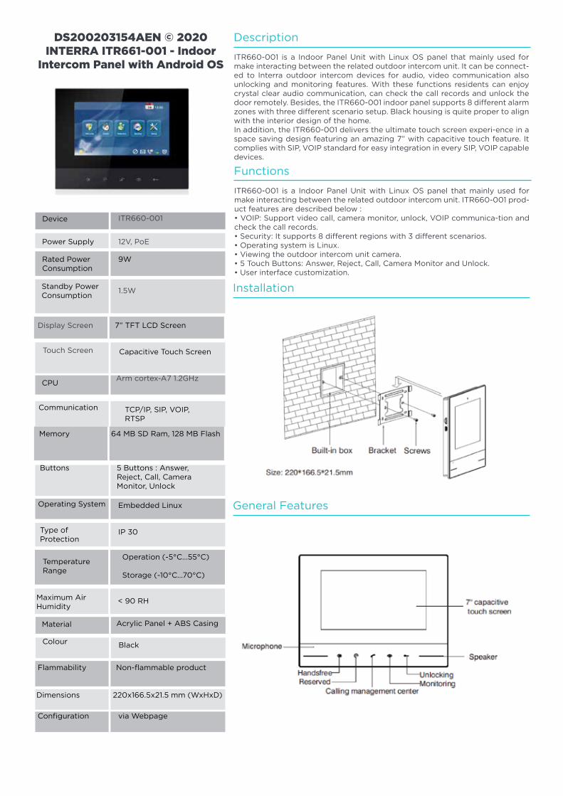
130
Display Screen
Touch Screen
ITR660-001
12V, PoE
9W
1.5W
DS200203154AEN © 2020 INTERRA ITR661-001 - Indoor
Intercom Panel with Android OS
Arm cortex-A7 1.2GHz
Button
Communication
Embedded Linux
TCP/IP, SIP, VOIP, RTSP
< 90 RH
Black
220x166.5x21.5 mm (WxHxD)
IP 30
7” TFT LCD Screen
Capacitive Touch Screen
Device
Power Supply
Rated PowerConsumption
Standby PowerConsumption
Operating System
Maximum AirHumidity
Colour
Type ofProtection
Acrylic Panel + ABS Casing
Non-flammable productFlammability
Dimensions
Configuration via Webpage
Operation (-5°C...55°C)
Storage (-10°C...70°C)
Material
TemperatureRange
CPU
Memory 64 MB SD Ram, 128 MB Flash
Buttons 5 Buttons : Answer, Reject, Call, Camera Monitor, Unlock
Description
Functions
Installation
General Features
ITR660-001 is a Indoor Panel Unit with Linux OS panel that mainly used for make interacting between the related outdoor intercom unit. It can be connect-ed to Interra outdoor intercom devices for audio, video communication also unlocking and monitoring features. With these functions residents can enjoy crystal clear audio communication, can check the call records and unlock the door remotely. Besides, the ITR660-001 indoor panel supports 8 different alarm zones with three different scenario setup. Black housing is quite proper to align with the interior design of the home.In addition, the ITR660-001 delivers the ultimate touch screen experi-ence in a space saving design featuring an amazing 7” with capacitive touch feature. It complies with SIP, VOIP standard for easy integration in every SIP, VOIP capable devices.
ITR660-001 is a Indoor Panel Unit with Linux OS panel that mainly used for make interacting between the related outdoor intercom unit. ITR660-001 prod-uct features are described below :• VOIP: Support video call, camera monitor, unlock, VOIP communica-tion and check the call records.• Security: It supports 8 different regions with 3 different scenarios.• Operating system is Linux.• Viewing the outdoor intercom unit camera.• 5 Touch Buttons: Answer, Reject, Call, Camera Monitor and Unlock.• User interface customization.
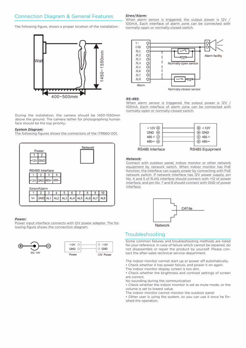
131
Connection Diagram & General Features
The following figure, shows a proper location of the installation :
During the installation, the camera should be 1450-1550mm above the ground. The camera tether for photographing human face should be the top priority.:
System Diagram:The following figures shows the connectors of the ITR660-001.
Power:Power input interface connects with 12V power adapter. The fol-lowing figure shows the connection diagram.
Siren/Alarm:When alarm sensor is triggered, the output power is 12V / 100mA. Each interface of alarm zone can be connected with normally-open or normally-closed switch.
RS-485:When alarm sensor is triggered, the output power is 12V / 100mA. Each interface of alarm zone can be connected with normally-open or normally-closed switch.
Network:Connect with outdoor panel, indoor monitor or other network equipment by network switch. When indoor monitor has PoE function, the interface can supply power by connecting with PoE network switch. If network interface has 12V power supply, pin No. 4 and 5 of RJ45 interface should connect with +12 of power interface, and pin No. 7 and 8 should connect with GND of power interface.
TroubleshootingSome common failures and troubleshooting methods are listed for your reference. In case of failure which cannot be repaired, do not disassemble or repair the product by yourself. Please con-tact the after-sales technical service department.
The indoor monitor cannot start up or power off automatically.• Check whether it has power failure, and power it on again.The indoor monitor display screen is too dim.• Check whether the brightness and contrast settings of screen are correct.No sounding during the communication• Check whether the indoor monitor is set as mute mode, or the volume is set to lowest value.The indoor monitor cannot monitor the outdoor panel• Other user is using the system, so you can use it once he fin-ished the operation.
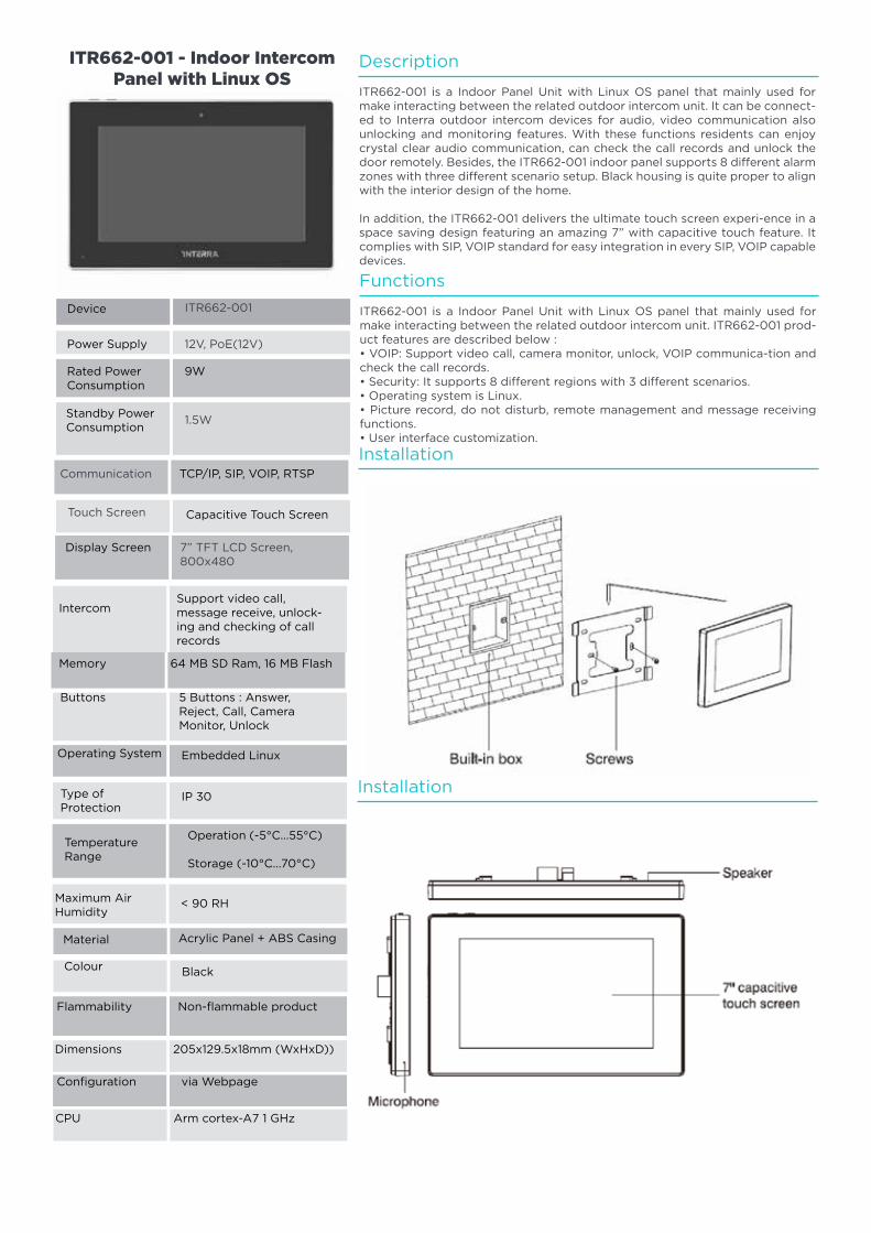
132
Communication
Touch Screen
ITR662-001
12V, PoE(12V)
9W
1.5W
ITR662-001 - Indoor Intercom Panel with Linux OS
7” TFT LCD Screen, 800x480
Button
Intercom
Embedded Linux
Support video call, message receive, unlock-ing and checking of call records
< 90 RH
Black
205x129.5x18mm (WxHxD))
Arm cortex-A7 1 GHz
IP 30
TCP/IP, SIP, VOIP, RTSP
Capacitive Touch Screen
Device
Power Supply
Rated PowerConsumption
Standby PowerConsumption
Operating System
Maximum AirHumidity
Colour
Type ofProtection
Acrylic Panel + ABS Casing
Non-flammable productFlammability
Dimensions
CPU
Configuration via Webpage
Operation (-5°C...55°C)
Storage (-10°C...70°C)
Material
TemperatureRange
Display Screen
Memory 64 MB SD Ram, 16 MB Flash
Buttons 5 Buttons : Answer, Reject, Call, Camera Monitor, Unlock
Description
Functions
Installation
Installation
ITR662-001 is a Indoor Panel Unit with Linux OS panel that mainly used for make interacting between the related outdoor intercom unit. It can be connect-ed to Interra outdoor intercom devices for audio, video communication also unlocking and monitoring features. With these functions residents can enjoy crystal clear audio communication, can check the call records and unlock the door remotely. Besides, the ITR662-001 indoor panel supports 8 different alarm zones with three different scenario setup. Black housing is quite proper to align with the interior design of the home.
In addition, the ITR662-001 delivers the ultimate touch screen experi-ence in a space saving design featuring an amazing 7” with capacitive touch feature. It complies with SIP, VOIP standard for easy integration in every SIP, VOIP capable devices.
ITR662-001 is a Indoor Panel Unit with Linux OS panel that mainly used for make interacting between the related outdoor intercom unit. ITR662-001 prod-uct features are described below :• VOIP: Support video call, camera monitor, unlock, VOIP communica-tion and check the call records.• Security: It supports 8 different regions with 3 different scenarios.• Operating system is Linux.• Picture record, do not disturb, remote management and message receiving functions.• User interface customization.
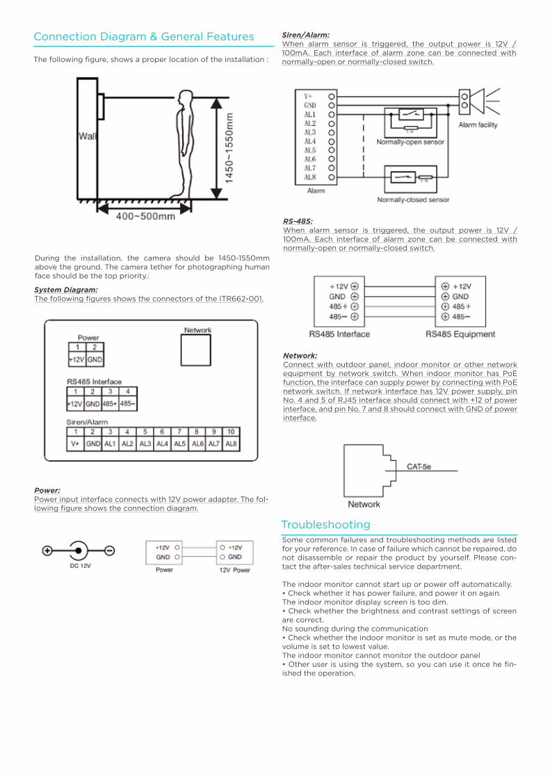
133
Connection Diagram & General Features
The following figure, shows a proper location of the installation :
During the installation, the camera should be 1450-1550mm above the ground. The camera tether for photographing human face should be the top priority.:
System Diagram:The following figures shows the connectors of the ITR662-001.
Power:Power input interface connects with 12V power adapter. The fol-lowing figure shows the connection diagram.
Siren/Alarm:When alarm sensor is triggered, the output power is 12V / 100mA. Each interface of alarm zone can be connected with normally-open or normally-closed switch.
RS-485:When alarm sensor is triggered, the output power is 12V / 100mA. Each interface of alarm zone can be connected with normally-open or normally-closed switch.
Network:Connect with outdoor panel, indoor monitor or other network equipment by network switch. When indoor monitor has PoE function, the interface can supply power by connecting with PoE network switch. If network interface has 12V power supply, pin No. 4 and 5 of RJ45 interface should connect with +12 of power interface, and pin No. 7 and 8 should connect with GND of power interface.
TroubleshootingSome common failures and troubleshooting methods are listed for your reference. In case of failure which cannot be repaired, do not disassemble or repair the product by yourself. Please con-tact the after-sales technical service department.
The indoor monitor cannot start up or power off automatically.• Check whether it has power failure, and power it on again.The indoor monitor display screen is too dim.• Check whether the brightness and contrast settings of screen are correct.No sounding during the communication• Check whether the indoor monitor is set as mute mode, or the volume is set to lowest value.The indoor monitor cannot monitor the outdoor panel• Other user is using the system, so you can use it once he fin-ished the operation.
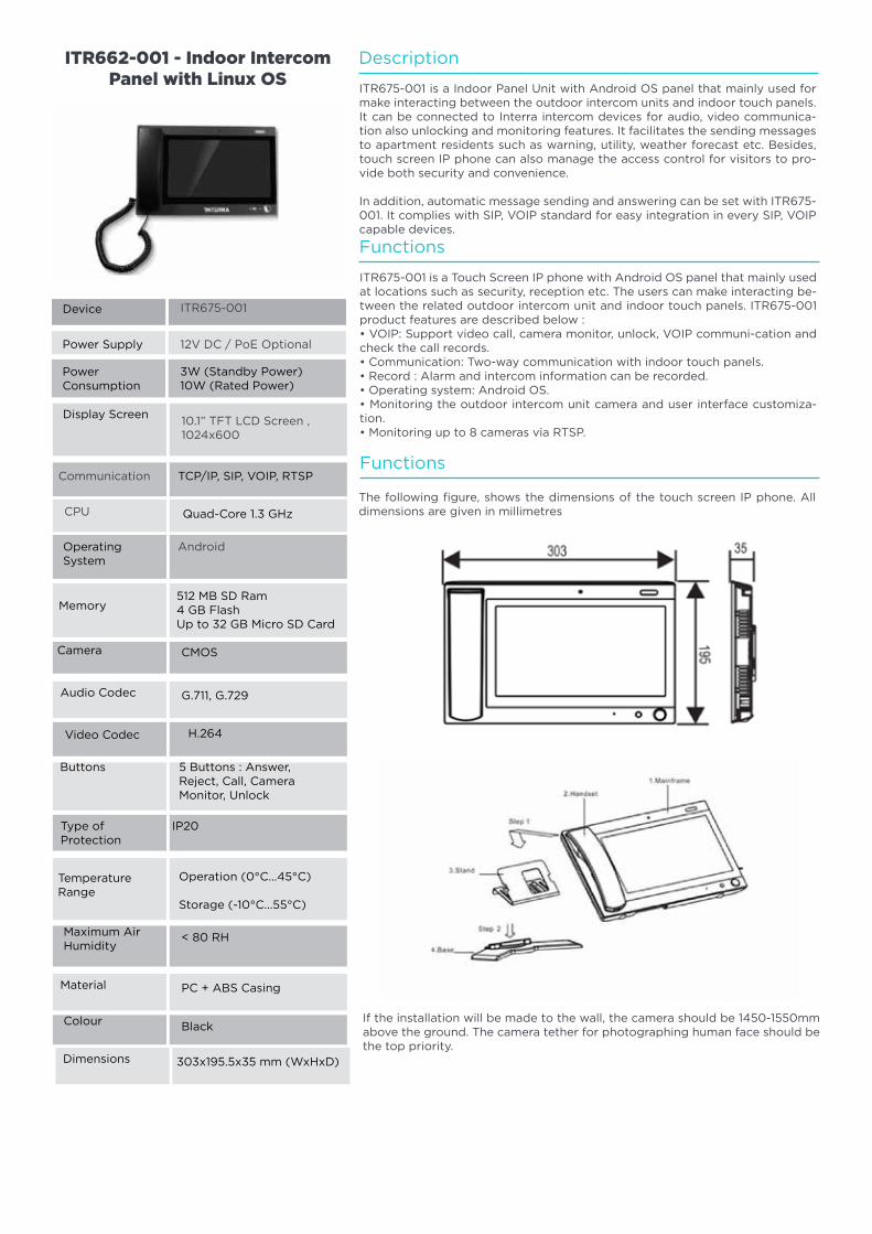
134
Communication
CPU
ITR675-001
12V DC / PoE Optional
3W (Standby Power)10W (Rated Power)
10.1” TFT LCD Screen , 1024x600
ITR662-001 - Indoor Intercom Panel with Linux OS
Android
Memory
CMOS
512 MB SD Ram4 GB FlashUp to 32 GB Micro SD Card
Operation (0°C...45°C)
Storage (-10°C...55°C)
< 80 RH
Black
G.711, G.729
PC + ABS Casing
303x195.5x35 mm (WxHxD)
TCP/IP, SIP, VOIP, RTSP
Quad-Core 1.3 GHz
Device
Power Supply
PowerConsumption
Display Screen
Camera
TemperatureRange
Maximum AirHumidity
Colour
Audio Codec
Material
Dimensions
H.264Video Codec
Operating System
Type ofProtection
IP20
Buttons 5 Buttons : Answer, Reject, Call, Camera Monitor, Unlock
Description
Functions
Functions
ITR675-001 is a Indoor Panel Unit with Android OS panel that mainly used for make interacting between the outdoor intercom units and indoor touch panels. It can be connected to Interra intercom devices for audio, video communica-tion also unlocking and monitoring features. It facilitates the sending messages to apartment residents such as warning, utility, weather forecast etc. Besides, touch screen IP phone can also manage the access control for visitors to pro-vide both security and convenience.
In addition, automatic message sending and answering can be set with ITR675-001. It complies with SIP, VOIP standard for easy integration in every SIP, VOIP capable devices.
The following figure, shows the dimensions of the touch screen IP phone. All dimensions are given in millimetres
If the installation will be made to the wall, the camera should be 1450-1550mm above the ground. The camera tether for photographing human face should be the top priority.
ITR675-001 is a Touch Screen IP phone with Android OS panel that mainly used at locations such as security, reception etc. The users can make interacting be-tween the related outdoor intercom unit and indoor touch panels. ITR675-001 product features are described below :• VOIP: Support video call, camera monitor, unlock, VOIP communi-cation and check the call records.• Communication: Two-way communication with indoor touch panels.• Record : Alarm and intercom information can be recorded.• Operating system: Android OS.• Monitoring the outdoor intercom unit camera and user interface customiza-tion.• Monitoring up to 8 cameras via RTSP.
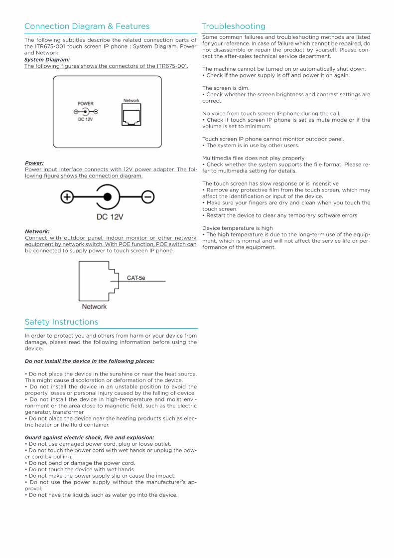
135
Connection Diagram & Features
Safety Instructions
The following subtitles describe the related connection parts of the ITR675-001 touch screen IP phone : System Diagram, Power and Network.
In order to protect you and others from harm or your device from damage, please read the following information before using the device.
Do not Install the device in the following places:
• Do not place the device in the sunshine or near the heat source. This might cause discoloration or deformation of the device.• Do not install the device in an unstable position to avoid the property losses or personal injury caused by the falling of device.• Do not install the device in high-temperature and moist envi-ron-ment or the area close to magnetic field, such as the electric generator, transformer• Do not place the device near the heating products such as elec-tric heater or the fluid container.
Guard against electric shock, fire and explosion:• Do not use damaged power cord, plug or loose outlet.• Do not touch the power cord with wet hands or unplug the pow-er cord by pulling.• Do not bend or damage the power cord.• Do not touch the device with wet hands.• Do not make the power supply slip or cause the impact.• Do not use the power supply without the manufacturer’s ap-proval.• Do not have the liquids such as water go into the device.
System Diagram:The following figures shows the connectors of the ITR675-001.
Power:Power input interface connects with 12V power adapter. The fol-lowing figure shows the connection diagram.
Network:Connect with outdoor panel, indoor monitor or other network equipment by network switch. With POE function, POE switch can be connected to supply power to touch screen IP phone.
TroubleshootingSome common failures and troubleshooting methods are listed for your reference. In case of failure which cannot be repaired, do not disassemble or repair the product by yourself. Please con-tact the after-sales technical service department.
The machine cannot be turned on or automatically shut down.• Check if the power supply is off and power it on again.
The screen is dim.• Check whether the screen brightness and contrast settings are correct.
No voice from touch screen IP phone during the call.• Check if touch screen IP phone is set as mute mode or if the volume is set to minimum.
Touch screen IP phone cannot monitor outdoor panel.• The system is in use by other users.
Multimedia files does not play properly• Check whether the system supports the file format. Please re-fer to multimedia setting for details.
The touch screen has slow response or is insensitive• Remove any protective film from the touch screen, which may affect the identification or input of the device.• Make sure your fingers are dry and clean when you touch the touch screen.• Restart the device to clear any temporary software errors
Device temperature is high• The high temperature is due to the long-term use of the equip-ment, which is normal and will not affect the service life or per-formance of the equipment.
136
Emergency Lighting
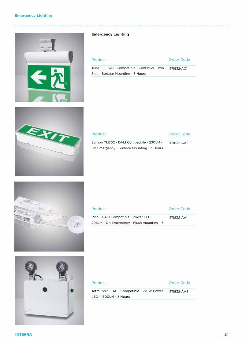
137
Emergency Lighting
Emergency Lighting
Order CodeProduct
ITR832-AC1Tuna - L - DALI Compatible - Continual - Two
Side - Surface Mounting - 3 Hours
Order CodeProduct
ITR832-AA2Somon XLED2 - DALI Compatible - 230LM -
On Emergency - Surface Mounting - 3 Hours
Order CodeProduct
ITR832-AA3Tetra PW3 - DALI Compatible - 2x9W Power
LED - 1500LM - 3 Hours
Order CodeProduct
ITR832-AA1Rina - DALI Compatible - Power LED -
205LM - On Emergency - Flush mounting - 3
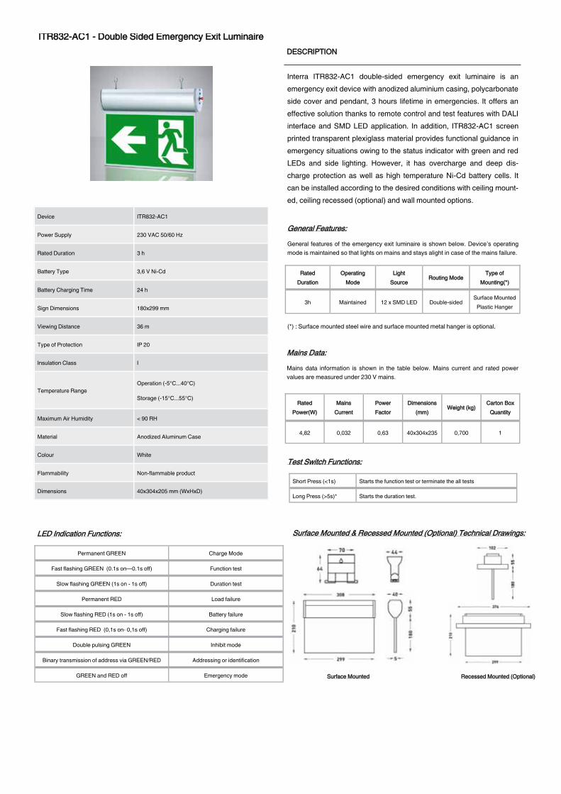
138
DS200529161AEN © 2020 INTERRA
IITTRR883322--AACC11 -- DDoouubbllee SSiiddeedd EEmmeerrggeennccyy EExxiitt LLuummiinnaaiirree DDEESSCCRRIIPPTTIIOONN
Interra ITR832-AC1 double-sided emergency exit luminaire is an emergency exit device with anodized aluminium casing, polycarbonate side cover and pendant, 3 hours lifetime in emergencies. It offers an effective solution thanks to remote control and test features with DALI interface and SMD LED application. In addition, ITR832-AC1 screen printed transparent plexiglass material provides functional guidance in emergency situations owing to the status indicator with green and red LEDs and side lighting. However, it has overcharge and deep dis-charge protection as well as high temperature Ni-Cd battery cells. It can be installed according to the desired conditions with ceiling mount-ed, ceiling recessed (optional) and wall mounted options.
11//11
Device ITR832-AC1
Power Supply 230 VAC 50/60 Hz
Rated Duration 3 h
Battery Type 3,6 V Ni-Cd
Battery Charging Time 24 h
Sign Dimensions 180x299 mm
Viewing Distance 36 m
Type of Protection IP 20
Insulation Class I
Temperature Range Operation (-5°C...40°C)
Storage (-15°C...55°C)
Maximum Air Humidity < 90 RH
Material Anodized Aluminum Case
Colour White
Flammability Non-flammable product
Dimensions 40x304x205 mm (WxHxD)
MMaaiinnss DDaattaa::
Mains data information is shown in the table below. Mains current and rated power values are measured under 230 V mains.
GGeenneerraall FFeeaattuurreess::
General features of the emergency exit luminaire is shown below. Device’s operating mode is maintained so that lights on mains and stays alight in case of the mains failure.
TTeesstt SSwwiittcchh FFuunnccttiioonnss::
Short Press (<1s) Starts the function test or terminate the all tests
Long Press (>5s)* Starts the duration test.
Note : The battery must be 100% full before the duration test can be started.
LLEEDD IInnddiiccaattiioonn FFuunnccttiioonnss::
Permanent GREEN Charge Mode
Fast flashing GREEN (0.1s on—0.1s off) Function test
Slow flashing GREEN (1s on - 1s off) Duration test
Permanent RED Load failure
Slow flashing RED (1s on - 1s off) Battery failure
Fast flashing RED (0,1s on- 0,1s off) Charging failure
Double pulsing GREEN Inhibit mode
Binary transmission of address via GREEN/RED Addressing or identification
GREEN and RED off Emergency mode
SSuurrffaaccee MMoouunntteedd && RReecceesssseedd MMoouunntteedd ((OOppttiioonnaall)) TTeecchhnniiccaall DDrraawwiinnggss::
WWiirriinngg DDiiaaggrraamm && RReecceesssseedd MMoouunnttiinngg HHoollee SSiizzee::
3X
Live Brown
Neutral Blue
Earth Yellow-Green
2X DALI Brown
DALI Blue
CCoolloorrss ooff SSuuppppllyy CCoorrdd
DDAALLII DDAALLII
EEaarrtthh NNeeuuttrraall UUnnsswwiittcchheedd LLiinnee ((LLiivvee))
55 mm
369 mm
SSuurrffaaccee MMoouunntteedd RReecceesssseedd MMoouunntteedd ((OOppttiioonnaall))
RRaatteedd DDuurraattiioonn
OOppeerraattiinngg MMooddee
LLiigghhtt SSoouurrccee
RRoouuttiinngg MMooddee TTyyppee ooff
MMoouunnttiinngg((**))
3h Maintained 12 x SMD LED Double-sided Surface Mounted
Plastic Hanger
RRaatteedd PPoowweerr((WW))
MMaaiinnss CCuurrrreenntt
PPoowweerr FFaaccttoorr
DDiimmeennssiioonnss ((mmmm))
WWeeiigghhtt ((kkgg)) CCaarrttoonn BBooxx
QQuuaannttiittyy
4,82 0,032 0,63 40x304x235 0,700 1
(*) : Surface mounted steel wire and surface mounted metal hanger is optional.
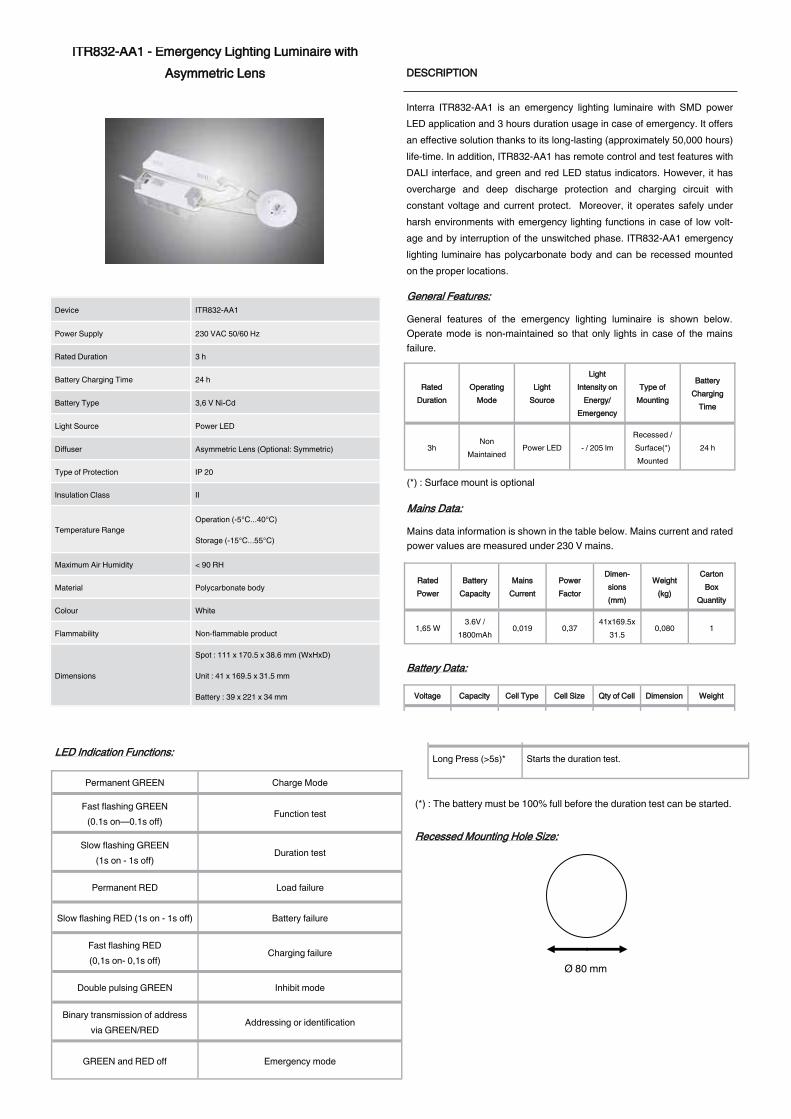
139
DS200529162AEN © 2020 INTERRA
IITTRR883322--AAAA11 -- EEmmeerrggeennccyy LLiigghhttiinngg LLuummiinnaaiirree wwiitthh AAssyymmmmeettrriicc LLeennss DDEESSCCRRIIPPTTIIOONN
Interra ITR832-AA1 is an emergency lighting luminaire with SMD power LED application and 3 hours duration usage in case of emergency. It offers an effective solution thanks to its long-lasting (approximately 50,000 hours) life-time. In addition, ITR832-AA1 has remote control and test features with DALI interface, and green and red LED status indicators. However, it has overcharge and deep discharge protection and charging circuit with constant voltage and current protect. Moreover, it operates safely under harsh environments with emergency lighting functions in case of low volt-age and by interruption of the unswitched phase. ITR832-AA1 emergency lighting luminaire has polycarbonate body and can be recessed mounted on the proper locations.
11//22
Device ITR832-AA1
Power Supply 230 VAC 50/60 Hz
Rated Duration 3 h
Battery Charging Time 24 h
Battery Type 3,6 V Ni-Cd
Light Source Power LED
Diffuser Asymmetric Lens (Optional: Symmetric)
Type of Protection IP 20
Insulation Class II
Temperature Range Operation (-5°C...40°C)
Storage (-15°C...55°C)
Maximum Air Humidity < 90 RH
Material Polycarbonate body
Colour White
Flammability Non-flammable product
Dimensions
Spot : 111 x 170.5 x 38.6 mm (WxHxD)
Unit : 41 x 169.5 x 31.5 mm
Battery : 39 x 221 x 34 mm
Ø 80 mm
MMaaiinnss DDaattaa::
Mains data information is shown in the table below. Mains current and rated power values are measured under 230 V mains.
GGeenneerraall FFeeaattuurreess::
General features of the emergency lighting luminaire is shown below. Operate mode is non-maintained so that only lights in case of the mains failure.
RRaatteedd DDuurraattiioonn
OOppeerraattiinngg MMooddee
LLiigghhtt SSoouurrccee
LLiigghhtt IInntteennssiittyy oonn
EEnneerrggyy// EEmmeerrggeennccyy
TTyyppee ooff MMoouunnttiinngg
BBaatttteerryy CChhaarrggiinngg
TTiimmee
3h Non
Maintained Power LED - / 205 lm
Recessed / Surface(*) Mounted
24 h
RRaatteedd PPoowweerr
MMaaiinnss CCuurrrreenntt
PPoowweerr FFaaccttoorr
DDiimmeenn--ssiioonnss ((mmmm))
WWeeiigghhtt ((kkgg))
CCaarrttoonn BBooxx
QQuuaannttiittyy
BBaatttteerryy CCaappaacciittyy
1,65 W 0,019 0,37 41x169.5x
31.5 0,080 1
3.6V / 1800mAh
TTeesstt SSwwiittcchh FFuunnccttiioonnss::
Short Press (<1s) Starts the function test or terminate the all tests
Long Press (>5s)* Starts the duration test.
(*) : The battery must be 100% full before the duration test can be started.
LLEEDD IInnddiiccaattiioonn FFuunnccttiioonnss::
Permanent GREEN Charge Mode
Fast flashing GREEN (0.1s on—0.1s off)
Function test
Slow flashing GREEN (1s on - 1s off)
Duration test
Permanent RED Load failure
Slow flashing RED (1s on - 1s off) Battery failure
Fast flashing RED (0,1s on- 0,1s off)
Charging failure
Double pulsing GREEN Inhibit mode
Binary transmission of address via GREEN/RED
Addressing or identification
GREEN and RED off Emergency mode
RReecceesssseedd MMoouunnttiinngg HHoollee SSiizzee::
VVoollttaaggee CCeellll TTyyppee CCeellll SSiizzee QQttyy ooff CCeellll DDiimmeennssiioonn WWeeiigghhtt CCaappaacciittyy
3.6 V SC 23 3 23x129±3
x23 0,150 1800 mAh
BBaatttteerryy DDaattaa::
(*) : Surface mount is optional
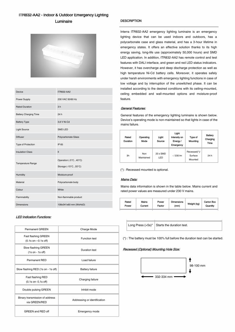
140
DS200529163AEN © 2020 INTERRA
IITTRR883322--AAAA22 -- IInnddoooorr && OOuuttddoooorr EEmmeerrggeennccyy LLiigghhttiinngg LLuummiinnaaiirree DDEESSCCRRIIPPTTIIOONN
Interra ITR832-AA2 emergency lighting luminaire is an emergency lighting device that can be used indoors and outdoors, has a polycarbonate case and glass material, and has a 3-hour lifetime in emergency states. It offers an effective solution thanks to its high energy saving, long-life use (approximately 50,000 hours) and SMD LED application. In addition, ITR832-AA2 has remote control and test features with DALI interface, and green and red LED status indicators. However, it has overcharge and deep discharge protection as well as high temperature Ni-Cd battery cells. Moreover, it operates safely under harsh environments with emergency lighting functions in case of low voltage and by interruption of the unswitched phase. It can be installed according to the desired conditions with its ceiling-mounted, ceiling embedded and wall-mounted options and moisture-proof feature.
11//22
Device ITR832-AA2
Power Supply 230 VAC 50/60 Hz
Rated Duration 3 h
Battery Charging Time 24 h
Battery Type 3,6 V Ni-Cd
Light Source SMD LED
Diffuser Polycarbonate Glass
Type of Protection IP 65
Insulation Class II
Temperature Range Operation (-5°C...40°C)
Storage (-15°C...55°C)
Humidity Moisture-proof
Material Polycarbonate body
Colour White
Flammability Non-flammable product
Dimensions 108x341x60 mm (WxHxD)
98-100 mm
332-334 mm
MMaaiinnss DDaattaa::
Mains data information is shown in the table below. Mains current and rated power values are measured under 230 V mains.
GGeenneerraall FFeeaattuurreess::
General features of the emergency lighting luminaire is shown below. Device’s operating mode is non-maintained so that lights in case of the mains failure.
RRaatteedd DDuurraattiioonn
OOppeerraattiinngg MMooddee
LLiigghhtt SSoouurrccee
LLiigghhtt IInntteennssiittyy oonn
EEnneerrggyy // EEmmeerrggeennccyy
TTyyppee ooff MMoouunnttiinngg
BBaatttteerryy CChhaarrggiinngg
TTiimmee
3h Non
Maintained 20 x SMD
LED - / 230 lm
Recessed(*)/ Surface Mounted
24 h
RRaatteedd PPoowweerr
MMaaiinnss CCuurrrreenntt
PPoowweerr FFaaccttoorr
DDiimmeennssiioonnss ((mmmm))
WWeeiigghhtt ((kkgg)) CCaarrttoonn BBooxx
QQuuaannttiittyy
1,65 W 0,019 0,37 108x341x60 0,690 1
TTeesstt SSwwiittcchh FFuunnccttiioonnss::
Short Press (<1s) Starts the function test or terminate the all tests
Long Press (>5s)* Starts the duration test.
(*) : The battery must be 100% full before the duration test can be started.
LLEEDD IInnddiiccaattiioonn FFuunnccttiioonnss::
Permanent GREEN Charge Mode
Fast flashing GREEN (0.1s on—0.1s off)
Function test
Slow flashing GREEN (1s on - 1s off)
Duration test
Permanent RED Load failure
Slow flashing RED (1s on - 1s off) Battery failure
Fast flashing RED (0,1s on- 0,1s off)
Charging failure
Double pulsing GREEN Inhibit mode
Binary transmission of address via GREEN/RED
Addressing or identification
GREEN and RED off Emergency mode
RReecceesssseedd ((OOppttiioonnaall)) MMoouunnttiinngg HHoollee SSiizzee::
(*) : Recessed mounted is optional.
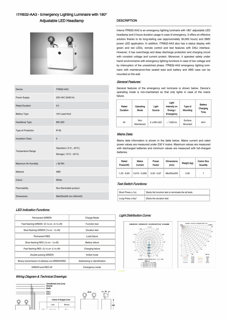
141
DS200529164AEN © 2020 INTERRA
IITTRR883322--AAAA33 -- EEmmeerrggeennccyy LLiigghhttiinngg LLuummiinnaaiirree wwiitthh 118800°AAddjjuussttaabbllee LLEEDD HHeeaaddllaammpp DDEESSCCRRIIPPTTIIOONN
Interra ITR832-AA3 is an emergency lighting luminaire with 180° adjustable LED headlamp and 3 hours duration usage in case of emergency. It offers an effective solution thanks to its long-lasting use (approximately 30,000 hours) and SMD power LED application. In addition, ITR832-AA3 also has a status display with green and red LEDs, remote control and test features with DALI interface. However, it has overcharge and deep discharge protection and charging circuit with constant voltage and current protect. Moreover, it operates safely under harsh environments with emergency lighting functions in case of low voltage and by interruption of the unswitched phase. ITR832-AA3 emergency lighting lumi-naire with maintenance-free sealed lead acid battery and ABS case can be mounted on the wall.
11//11
Device ITR832-AA3
Power Supply 230 VAC 50/60 Hz
Rated Duration 3 h
Battery Type 12V Lead-Acid
Headlamp Type 9W LED
Type of Protection IP 65
Insulation Class II
Temperature Range Operation (-5°C...40°C)
Storage (-15°C...55°C)
Maximum Air Humidity < 90 RH
Material ABS
Colour White
Flammability Non-flammable product
Dimensions 98x255x205 mm (WxHxD)
MMaaiinnss DDaattaa::
Mains data information is shown in the table below. Mains current and rated power values are measured under 230 V mains. Maximum values are measured with discharged batteries and minimum values are measured with full-charged batteries.
GGeenneerraall FFeeaattuurreess::
General features of the emergency exit luminaire is shown below. Device’s operating mode is non-maintained so that only lights in case of the mains failure.
TTeesstt SSwwiittcchh FFuunnccttiioonnss::
Short Press (<1s) Starts the function test or terminate the all tests
Long Press (>5s)* Starts the duration test.
(*) : The battery must be 100% full before the duration test can be started.
LLEEDD IInnddiiccaattiioonn FFuunnccttiioonnss::
Permanent GREEN Charge Mode
Fast flashing GREEN (0.1s on—0.1s off) Function test
Slow flashing GREEN (1s on - 1s off) Duration test
Permanent RED Load failure
Slow flashing RED (1s on - 1s off) Battery failure
Fast flashing RED (0,1s on- 0,1s off) Charging failure
Double pulsing GREEN Inhibit mode
Binary transmission of address via GREEN/RED Addressing or identification
GREEN and RED off Emergency mode
LLiigghhtt DDiissttrriibbuuttiioonn CCuurrvvee::
WWiirriinngg DDiiaaggrraamm && TTeecchhnniiccaall DDrraawwiinnggss::
3X
Live Brown
Neutral Blue
Earth Yellow-Green
2X DALI Brown
DALI Blue
CCoolloorrss ooff SSuuppppllyy CCoorrdd
DDAALLII DDAALLII
EEaarrtthh NNeeuuttrraall UUnnsswwiittcchheedd LLiinnee ((LLiivvee))
RRaatteedd DDuurraattiioonn
OOppeerraattiinngg MMooddee
LLiigghhtt SSoouurrccee
LLiigghhtt IInntteennssiittyy oonn
EEnneerrggyy // EEmmeerrggeennccyy
TTyyppee ooff MMoouunnttiinngg
BBaatttteerryy CChhaarrggiinngg
TTiimmee
3h Non
Maintained 2 x 9W LED - / 1500 lm
Surface Mounted
48 h
RRaatteedd PPoowweerr((WW))
MMaaiinnss CCuurrrreenntt
PPoowweerr FFaaccttoorr
DDiimmeennssiioonnss ((mmmm))
WWeeiigghhtt ((kkgg)) CCaarrttoonn BBooxx
QQuuaannttiittyy
1,25 - 8,90 0,010 - 0,058 0,50 - 0,67 98x255x205 4,50 1
Above curve is measured data just for one headlamp.

142

143
Gen
era
l-C
ata
log
ue-v
ers
ion
1
interratechnology.com
Related Documents