RAMC with housing type 90 RAMC with housing type 91 GS 01R01B02-00E-E © Copyright October 2004 (Rü) 24th edition, September 2014 (Rü) Model RAMC Metal Short-stroke Rotameter A float is guided concentrically to a special shaped conic metal tube. The position of this float is magnetically transmitted to the indicator. The short-tube Rotameter is used for measurement of flow rates of liquids and gases. Its special application is in troubled, opaque or aggressive mediums. The instrument is mounted in a vertical pipeline with flow direction upwards. The indicators are exchangeable without influence on the accuracy. FEATURES - Different process connections like flanges according EN and ASME - All wetted parts in stainless steel or PTFE - Maximum flow 0.025 - 130 m³/h water resp. 0.75 - 1400 m³/h air (20 °C / 1.013 bar abs) - Measuring accuracy acc. Directive VDI/VDE 3513 sheet 2 (q G =50%) - Float damping to avoid float bouncing with gas applications - Optional heat tracing (with steam or fluid heat carrier) - Indicator in stainless steel, aluminium, protection class IP66/67 - Local indicator without additional power supply - Microprocessor controlled transmitter with 24 V, 115 V or 230 V power supply - Intrinsically safe version (Ex-i): ATEX, IECEx, FM, CSA, NEPSI, PESO, KOSHA, EAC - Flame proof version (Ex-d): ATEX, IECEx, NEPSI, PESO, KOSHA, EAC - Dust explosion proof: ATEX, IECEx, NEPSI, PESO, KOSHA - Suitable for SIL application, FMEDA report available - Limit switches, also available as “Fail Safe” version Electronic transmitter as standard with local-controlling display with the following features : - Flow indication (totalize, actual, percent) - Indication of different volume- and mass flow units - Second (manual) calibration storing - Patented float blocking indication function - Signal output damping - Error message indication - Temperature measurement in the electronic transmitter - HART5- communication - Profibus PA- communication Contents Features page 1 Standard Specifications page 2 Compliance with IEC 61508 page 4 Compliance with ISO 13849 page 4 Hazardous Area Specifications page 5 Installation page 10 Model Specifications page 13 Options page 14 Process connection table for metal tubes page 16 Flow tables metal tubes page 17 Process connection and flow table for tubes with PTFE lining page 18 Temperature graphs page 19 Minumum ambient temperature page 20 Pressure rating page 21 Dimensions and weights page 22 General Specifications Rota Yokogawa GmbH & Co. KG Rheinstr. 8 D-79664 Wehr Germany GS 01R01B02-00E-E

Welcome message from author
This document is posted to help you gain knowledge. Please leave a comment to let me know what you think about it! Share it to your friends and learn new things together.
Transcript

RAMC with housing type 90
RAMC with housing type 91
GS 01R01B02-00E-E© Copyright October 2004 (Rü)
24th edition, September 2014 (Rü)
Model RAMCMetal Short-stroke Rotameter
A float is guided concentrically to a special shaped conic metal tube. The position of this float is magnetically transmitted to the indicator. The short-tube Rotameter is used for measurement of flow rates of liquids and gases. Its special application is in troubled, opaque or aggressive mediums. The instrument is mounted in a vertical pipeline with flow direction upwards.The indicators are exchangeable without influence on theaccuracy.
FEATURES- Different process connections like flanges according EN and ASME- All wetted parts in stainless steel or PTFE- Maximum flow 0.025 - 130 m³/h water resp. 0.75 - 1400 m³/h air (20 °C / 1.013 bar abs)- Measuring accuracy acc. Directive VDI/VDE 3513 sheet 2 (qG=50%)- Float damping to avoid float bouncing with gas applications- Optional heat tracing (with steam or fluid heat carrier)- Indicator in stainless steel, aluminium, protection class IP66/67- Local indicator without additional power supply- Microprocessor controlled transmitter with 24 V, 115 V or 230 V power supply- Intrinsically safe version (Ex-i): ATEX, IECEx, FM, CSA, NEPSI, PESO, KOSHA, EAC- Flame proof version (Ex-d): ATEX, IECEx, NEPSI, PESO, KOSHA, EAC- Dust explosion proof: ATEX, IECEx, NEPSI, PESO, KOSHA- Suitable for SIL application, FMEDA report available- Limit switches, also available as “Fail Safe” version Electronic transmitter as standard with local-controlling display with the following features :- Flow indication (totalize, actual, percent)- Indication of different volume- and mass flow units- Second (manual) calibration storing- Patented float blocking indication function- Signal output damping- Error message indication- Temperature measurement in the electronic transmitter- HART5- communication- Profibus PA- communication
ContentsFeatures page 1Standard Specifications page 2Compliance with IEC 61508 page 4Compliance with ISO 13849 page 4Hazardous Area Specifications page 5Installation page 10Model Specifications page 13Options page 14Process connection table for metal tubes page 16Flow tables metal tubes page 17
Process connection and flow table for tubes with PTFE lining
page 18
Temperature graphs page 19Minumum ambient temperature page 20Pressure rating page 21Dimensions and weights page 22
GeneralSpecifications
Rota Yokogawa GmbH & Co. KGRheinstr. 8D-79664 WehrGermany
GS 01R01B02-00E-E
GS 01R01B02-00E-E 24th edition, September 16, 2014-00
2
All Rights Reserved. Copyright © 2004, Rota Yokogawa
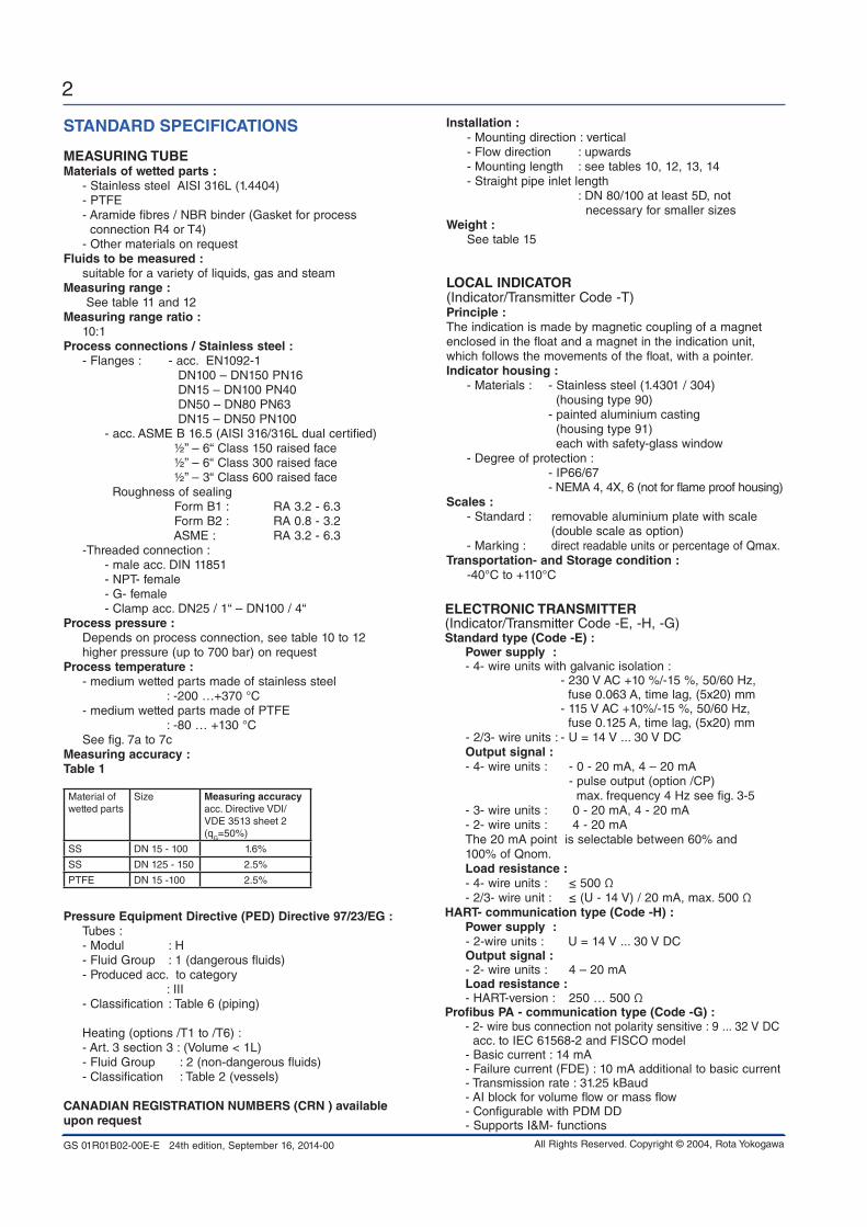
STAndARd SpECiFiCATionS
MEASURinG TUbEMaterials of wetted parts : - Stainless steel AISI 316L (1.4404) - PTFE - Aramide fibres / NBR binder (Gasket for process connection R4 or T4) - Other materials on requestFluids to be measured : suitable for a variety of liquids, gas and steamMeasuring range : See table 11 and 12Measuring range ratio : 10:1process connections / Stainless steel : - Flanges : - acc. EN1092-1 DN100 – DN150 PN16 DN15 – DN100 PN40 DN50 – DN80 PN63 DN15 – DN50 PN100 - acc. ASME B 16.5 (AISI 316/316L dual certified) ½” – 6“ Class 150 raised face ½” – 6“ Class 300 raised face ½” – 3“ Class 600 raised face Roughness of sealing Form B1 : RA 3.2 - 6.3 Form B2 : RA 0.8 - 3.2 ASME : RA 3.2 - 6.3 -Threaded connection : - male acc. DIN 11851 - NPT- female - G- female - Clamp acc. DN25 / 1“ – DN100 / 4“process pressure : Depends on process connection, see table 10 to 12 higher pressure (up to 700 bar) on request process temperature : - medium wetted parts made of stainless steel : -200 …+370 °C - medium wetted parts made of PTFE : -80 … +130 °C See fig. 7a to 7cMeasuring accuracy : Table 1
Material of wetted parts
Size Measuring accuracy acc. Directive VDI/VDE 3513 sheet 2 (qG=50%)
SS DN 15 - 100 1.6%
SS DN 125 - 150 2.5%
PTFE DN 15 -100 2.5%
pressure Equipment directive (pEd) directive 97/23/EG : Tubes : - Modul : H - Fluid Group : 1 (dangerous fluids) - Produced acc. to category : III - Classification : Table 6 (piping) Heating (options /T1 to /T6) : - Art. 3 section 3 : (Volume < 1L) - Fluid Group : 2 (non-dangerous fluids) - Classification : Table 2 (vessels)
CAnAdiAn REGiSTRATion nUMbERS (CRn ) available upon request
installation : - Mounting direction : vertical - Flow direction : upwards - Mounting length : see tables 10, 12, 13, 14 - Straight pipe inlet length : DN 80/100 at least 5D, not necessary for smaller sizesWeight : See table 15
LoCAL indiCAToR(Indicator/Transmitter Code -T)principle : The indication is made by magnetic coupling of a magnet enclosed in the float and a magnet in the indication unit, which follows the movements of the float, with a pointer.indicator housing : - Materials : - Stainless steel (1.4301 / 304) (housing type 90) - painted aluminium casting (housing type 91) each with safety-glass window - Degree of protection : - IP66/67 - NEMA 4, 4X, 6 (not for flame proof housing)Scales : - Standard : removable aluminium plate with scale (double scale as option) - Marking : direct readable units or percentage of Qmax.Transportation- and Storage condition : -40°C to +110°C
ELECTRoniC TRAnSMiTTER(Indicator/Transmitter Code -E, -H, -G)Standard type (Code -E) : power supply : - 4- wire units with galvanic isolation : - 230 V AC +10 %/-15 %, 50/60 Hz, fuse 0.063 A, time lag, (5x20) mm - 115 V AC +10%/-15 %, 50/60 Hz, fuse 0.125 A, time lag, (5x20) mm - 2/3- wire units : - U = 14 V ... 30 V DC output signal : - 4- wire units : - 0 - 20 mA, 4 – 20 mA - pulse output (option /CP) max. frequency 4 Hz see fig. 3-5 - 3- wire units : 0 - 20 mA, 4 - 20 mA - 2- wire units : 4 - 20 mA The 20 mA point is selectable between 60% and 100% of Qnom. Load resistance : - 4- wire units : ≤ 500 Ω - 2/3- wire unit : ≤ (U - 14 V) / 20 mA, max. 500 ΩHART- communication type (Code -H) : power supply : - 2-wire units : U = 14 V ... 30 V DC output signal : - 2- wire units : 4 – 20 mA Load resistance : - HART-version : 250 … 500 Ωprofibus pA - communication type (Code -G) : - 2- wire bus connection not polarity sensitive : 9 ... 32 V DC acc. to IEC 61568-2 and FISCO model - Basic current : 14 mA - Failure current (FDE) : 10 mA additional to basic current - Transmission rate : 31.25 kBaud - AI block for volume flow or mass flow - Configurable with PDM DD - Supports I&M- functions

GS 01R01B02-00E-E 24th edition, September 16, 2014-00
3
All Rights Reserved. Copyright © 2004, Rota Yokogawa
LiMiT SWiTCHES in STAndARd vERSion (option /K1 to /K3)Type : Inductive proximity switch SC3.5-N0 acc. DIN EN 60947-5-6 nominal voltage : 8 V DCoutput signal : ≤ 1 mA or ≥ 3 mA
LiMiT SWiTCHES in FAiL SAFE vERSion (option /K6 to /K10)Type : Inductive proximity switch SJ3.5-SN; SJ3.5-S1N acc. DIN EN 60947-5-6 (NAMUR)nominal voltage : 8 V DCoutput signal : ≤ 1 mA or ≥ 3 mA
HYSTERESiS oF LiMiT SWiTCHESMin-contact / Max-contact : - pointer movement ≈ 0.8 mm - float movement ≈ 0.8 mmMinimum distance between 2 contacts : ≈ 2 mm
CAbLE GLAnd (option /K1 to /K10)Size : - M16x1.5 (standard) - Thread M20x1.5 (option /A13; standard for option /KF1) - Thread ½” NPT (option /A5)Cable diameter : 6 – 9 mmMaximum cross section of core : Ø 1.5 mm²
poWER SUppLY FoR LiMiT SWiTCHES (Option /W__) Type : acc. DIN EN 60947-5-6 (NAMUR) - KFA5-SR2-Ex*-W (115 V AC), * = 1 or 2 - KFA6-SR2-Ex*-W (230 V AC), * = 1 or 2 - KFD2-SR2-Ex*-W (24 V DC), * = 1 or 2 - KHA6-SH-Ex1 (115/230 V AC), Fail Safe, 1 channel - KFD2-SH-Ex1 (24 V DC), Fail Safe, 1 channel power supply : - 230 V AC ± 10%, 45-65Hz - 115 V AC ± 10%, 45-65Hz - 24 V DC ± 25%Relay output : 1 or 2 potential-free changeover contact(s) Switching capacity : max. 250 V AC, max. 2 A
note :If Fail-Safe limit switch option /K6 or /K7 is ordered, for power supply option /W2E or /W4E must be selected.If Fail-Safe limit switch option /K8, /K9 or /K10 is ordered, for power supply option /W2F or /W4F must be selected.
1) referenced to 20°C ambient temperature
digital display : 8- digits 7- segment-LC-display character height 6 mmprocess-/ Ambient temperature : The dependency of the process temperature from the ambient temperature is shown in fig. 7a to fig. 7c. The internal temperature of the electronic transmitter can be indicated on the display or checked via HART communication.Measurement of the internal transmitter temperature : - Range : -25 °C to +70 °C - Accuracy : ± 5 °CTransportation- and Storage condition : -40 °C to +70 °CLinearity 1) : ± 0.2 % f.s.Hysteresis 1) : ± 0.1 % f.s.Repeatability 1) : ± 0.1 % f.s.influence of power supply 1) : ± 0.1 % f.s.Temperature coefficient of the output signal 1) : ± 0.5 % /10 K f.s.AC-part of output signal 1) : ± 0.15 % f.s.Long-time stability 1) : ± 0.2 % /yearMax. output signal : 21.5 mAoutput signal in case of failure : ≤ 3.6 mA (acc. NE 43)Response time (99%) : About 1.5 s (damping 1s)Electromagnetic compatibility (EMC) : - Acc. EN 61326-1: 2006, Class A, Table 2 and EN 61326-2-3 : 2006 : Criterion A, restriction: HF- immunity between 500 MHz and 750 MHz : criterion B RAMC with Profibus PA : Criterion A: Burst, Surge, HF- Immunity Criterion B: ESD In case of single sided grounding of the cable shield it is possible that for all tests criterion B is reached.Unit safety acc. En 61010-1: 2010 : - Over voltage category : II (acc. VDE 0110 or IEC 664) - Pollution degree : I - Safety class : I (with 115 / 230V AC power supply) III (with 24V DC power supply and Fieldbus type)
poWER SUppLY FoR ELECTRoniC TRAnSMiTTER (Option /UT)Type : Power supply with galvanically separated input and output - RN221N-B1, HART- compatibleSupply voltage : 20 ... 250 V DC / AC 50/60 Hz Maximum load : 700 Ωoutput signal : 4 - 20 mA
CAbLE GLAnd (for transmitter –E, -H and –G) :Size : - M16x1.5 (standard) - Thread M20x1.5 (option /A13; standard for option /KF1) - Thread ½” NPT (option /A5)Cable diameter : 6 – 9 mmMaximum cross section of core : Ø 1.5 mm²

GS 01R01B02-00E-E 24th edition, September 16, 2014-00
4
All Rights Reserved. Copyright © 2004, Rota Yokogawa
CoMpLiAnCE WiTH iEC 61508RAMC with local indicator and fail safe limit switches (-T[][]nnn /K6 ... /K10):Suitable for application in safety functions up to and including SIL2.RAMC with local indicator and standard limit switches (-T[][]nnn /K1 ... /K3):Suitable for application in safety functions up to and including SIL2.RAMC with 4-20mA output (-E[][]424 and -H[][]424):Suitable for application in safety functions up to and including SIL1, but only with activated Float Blocking Indication.
Reliability data available on request in FMEDA report.
CoMpLiAnCE WiTH iSo 13849For Safety Metrics acc. to ISO 13849-2 please refer to the FMEDA report.
METRoLoGiCAL REGULATion in CiS And EAC CoUnTRiESRussia, Kazakhstan, Uzbekistan, Ukraine and Belorussia are members of CIS.RAMC has “Pattern Approval Certificate of Measuring Instruments” and is registered as a measuring instrument in Russia, Kazakhstan, Uzbekistan. Option /QR1 is for Russia.Option /QR2 is for Kazakhstan.Option /QR3 is for Uzbekistan.For the Ukraine the test certificate of Rota Yokogawa is sufficient. Therefore no special option exists. For Belorussia Rota Yokogawa has no “Pattern Approval Certificate”, that means devices which need primary verification should be calibrated in Belarus by Belorussian special bod-ies. Therefore no special option exists.
Russia, Kazakhstan and Belorussia are covered by EAC.For export to CIS and EAC countries please contact your Yokogawa representative.
SWiTCHinG LEvELS FoR LiMiT SWiTCHES Table 2 Min, Max and Min-Max-contact in standard version
option /K1 option /K2 option /K3
Function pointerSignal Signal Signal
SC3,5-n0 SC3,5-n0 SC3,5-n0
MAXabove LV below LV
---- ----
1 mA 3 mA
1 mA 3 mA
Function pointerSignal Signal Signal
SC3,5-n0 SC3,5-n0 SC3,5-n0
MINabove LV below LV
3 mA 1 mA
---- ----
3 mA 1 mA
Note: LV = Limit value
Table 3 Min, Max and Min-Max-contact in fail-safe version
option /K6 option /K7 option /K8
Function pointerSignal Signal Signal
SJ3,5-Sn SJ3,5-Sn SJ3,5-Sn
MAXabove LV below LVFail Safe
---- --------
1 mA 3 mA1 mA
1 mA 3 mA1 mA
Function pointerSignal Signal Signal
SJ3,5-Sn SJ3,5-Sn SJ3,5-Sn
MINabove LV below LVFail Safe
3 mA 1 mA1 mA
---- --------
3 mA 1 mA1 mA
Note: LV = Limit value
Table 4 Limit switch as Min-Min-contact in fail-safe version
option /K9
Function pointerSignal
SJ3,5-S1n
MINabove LV below LVFail Safe
3 mA 1 mA1 mA
Function pointerSignal
SJ3,5-Sn
MINabove LV below LVFail Safe
3 mA 1 mA1 mA
Note: LV = Limit value
Table 5 Limit switch as Max-Max-contact in fail-safe version
option /K10
Function pointerSignal
SJ3,5-Sn
MAXabove LV below LVFail Safe
1 mA 3 mA1 mA
Function pointerSignal
SJ3,5-S1n
MAXabove LV below LVFail Safe
1 mA 3 mA1 mA
Note: LV = Limit value

GS 01R01B02-00E-E 24th edition, September 16, 2014-00
5
All Rights Reserved. Copyright © 2004, Rota Yokogawa
HAzARdoUS AREA SpECiFiCATionS
overview hazardous area certified instruments:Location Europe Global USA Canada india Korea China Russia,
Belorussia,Kazakhstan
Certificate ATEX iECEx FM FM pESo KoSHA nEpSi EAC
Electronic transmitter (WT-MAG)
protection ia ic ia/tb ia ic ia/tb IS/Nl IS/Nl ia ia - ia
option /KS1 /KS3 /KS2 /ES1 /ES3 /ES2 /FS1 /CS1 /KS1 /ES1 - /GS1
Comments *2) *1) *2) *1) *3) *3) *4) -
See page 6 6 9 6 6 9 6 6 6 6 - 6
Limit switches
protection ia/iaD ic ia/tb ia - ia/tb IS/Nl IS/Nl - - ia - ia
option /KS1 /KS3 /KS2 /ES1 - /ES2 /FS1 /CS1 - - /NS1 - /GS1
Comments *2) *1) - *1) *5) *6) - - -
See page 7 7 9 7 - 9 7 7 - - 7 - 7
RAMC indicator
protection d/tb - d/tb - - - d d/tb ia d/DIP d
option /KF1 - /EF1 - - - /KF1 /EF1 /NS1 /NF1 /GF1
Comments *7) - *7) - - - *4) *7) *7)
See page 8 - 8 - - - 8 8 6 8 8
power supplies for intrinsic safe components (see page 7)
option /UT yes yes yes yes no no yes no
option /W1A,b yes yes yes yes yes yes no no
option /W2A,b yes yes yes yes yes yes no no
option /W4A,b yes yes yes yes yes yes yes no
option /W2E,F yes yes no no no no no no
option /W4E,F yes yes no no no no yes no
Notation IS = intrinsic safe; Nl = non incendive; DIP = dust ignition proof
Comment *1) Dust proof by RAMC housing
Comment *2) For use in category 3G
Comment *3) Same certification for USA and Canada
Comment *4) PESO certificate available from Yokogawa Sales Office
Comment *5) Only for USA; power supply free selectable
Comment *6) For USA and Canada; power supply must be option /WxA or /WxB (x=1 or 2 or 4)
Comment *7) Only with housing 91
GS 01R01B02-00E-E 24th edition, September 16, 2014-00
6
All Rights Reserved. Copyright © 2004, Rota Yokogawa
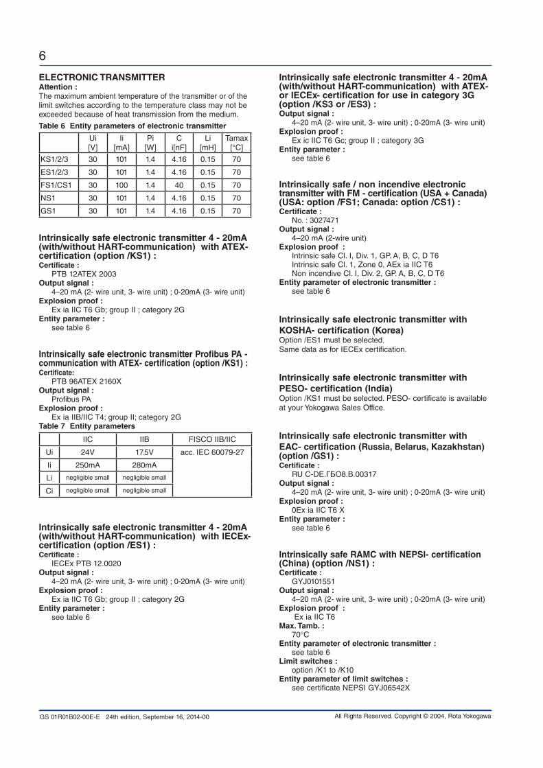
ELECTRoniC TRAnSMiTTERAttention :The maximum ambient temperature of the transmitter or of the limit switches according to the temperature class may not be exceeded because of heat transmission from the medium.
Table 6 Entity parameters of electronic transmitter
Ui[V]
Ii[mA]
Pi[W]
Ci[nF]
Li[mH]
Tamax [°C]
KS1/2/3 30 101 1.4 4.16 0.15 70
ES1/2/3 30 101 1.4 4.16 0.15 70
FS1/CS1 30 100 1.4 40 0.15 70
NS1 30 101 1.4 4.16 0.15 70
GS1 30 101 1.4 4.16 0.15 70
intrinsically safe electronic transmitter 4 - 20mA (with/without HART-communication) with ATEX- certification (option /KS1) :Certificate : PTB 12ATEX 2003output signal : 4–20 mA (2- wire unit, 3- wire unit) ; 0-20mA (3- wire unit)Explosion proof : Ex ia IIC T6 Gb; group II ; category 2GEntity parameter : see table 6
intrinsically safe electronic transmitter profibus pA -communication with ATEX- certification (option /KS1) :Certificate: PTB 96ATEX 2160Xoutput signal : Profibus PAExplosion proof : Ex ia IIB/IIC T4; group II; category 2GTable 7 Entity parameters
IIC IIB FISCO IIB/IIC
Ui 24V 17.5V acc. IEC 60079-27
Ii 250mA 280mA
Li negligible small negligible small
Ci negligible small negligible small
intrinsically safe electronic transmitter 4 - 20mA (with/without HART-communication) with iECEx- certification (option /ES1) :Certificate : IECEx PTB 12.0020output signal : 4–20 mA (2- wire unit, 3- wire unit) ; 0-20mA (3- wire unit)Explosion proof : Ex ia IIC T6 Gb; group II ; category 2G Entity parameter : see table 6
intrinsically safe electronic transmitter 4 - 20mA (with/without HART-communication) with ATEX- or iECEx- certification for use in category 3G (option /KS3 or /ES3) :output signal : 4–20 mA (2- wire unit, 3- wire unit) ; 0-20mA (3- wire unit)Explosion proof : Ex ic IIC T6 Gc; group II ; category 3G Entity parameter : see table 6
intrinsically safe / non incendive electronic transmitter with FM - certification (USA + Canada) (USA: option /FS1; Canada: option /CS1) :Certificate : No. : 3027471output signal : 4–20 mA (2-wire unit)Explosion proof : Intrinsic safe Cl. I, Div. 1, GP. A, B, C, D T6 Intrinsic safe Cl. 1, Zone 0, AEx ia IIC T6 Non incendive Cl. I, Div. 2, GP. A, B, C, D T6 Entity parameter of electronic transmitter : see table 6
intrinsically safe electronic transmitter with KoSHA- certification (Korea) Option /ES1 must be selected. Same data as for IECEx certification.
intrinsically safe electronic transmitter with pESo- certification (india) Option /KS1 must be selected. PESO- certificate is available at your Yokogawa Sales Office.
intrinsically safe electronic transmitter with EAC- certification (Russia, belarus, Kazakhstan) (option /GS1) :Certificate : RU С-DЕ.ГБО8.В.00317output signal : 4–20 mA (2- wire unit, 3- wire unit) ; 0-20mA (3- wire unit)Explosion proof : 0Ex ia IIC T6 XEntity parameter : see table 6
intrinsically safe RAMC with nEpSi- certification (China) (option /nS1) :Certificate : GYJ0101551output signal : 4–20 mA (2- wire unit, 3- wire unit) ; 0-20mA (3- wire unit)Explosion proof : Ex ia IIC T6Max. Tamb. : 70°C Entity parameter of electronic transmitter : see table 6Limit switches : option /K1 to /K10Entity parameter of limit switches : see certificate NEPSI GYJ06542X
GS 01R01B02-00E-E 24th edition, September 16, 2014-00
7
All Rights Reserved. Copyright © 2004, Rota Yokogawa
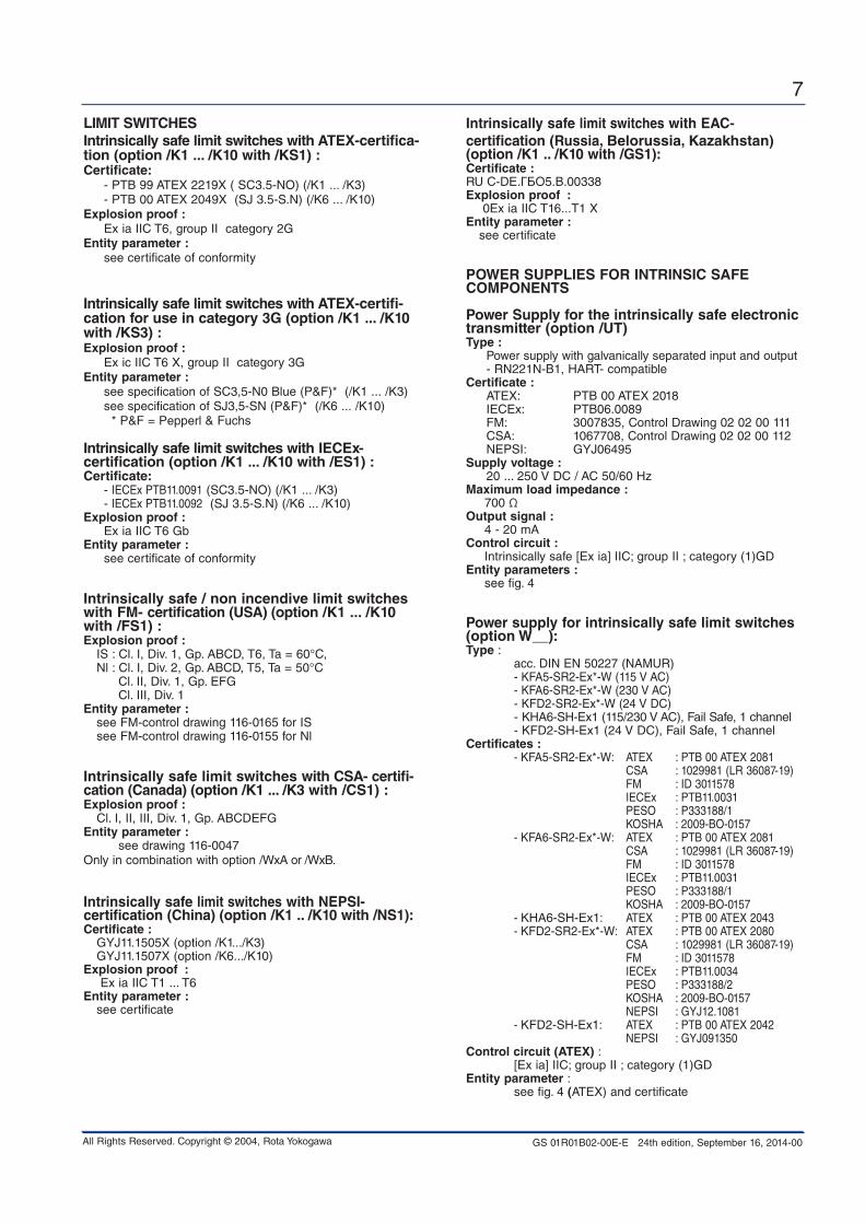
LiMiT SWiTCHESintrinsically safe limit switches with ATEX-certifica-tion (option /K1 ... /K10 with /KS1) :Certificate: - PTB 99 ATEX 2219X ( SC3.5-NO) (/K1 ... /K3) - PTB 00 ATEX 2049X (SJ 3.5-S.N) (/K6 ... /K10)Explosion proof : Ex ia IIC T6, group II category 2GEntity parameter : see certificate of conformity
intrinsically safe limit switches with ATEX-certifi-cation for use in category 3G (option /K1 ... /K10 with /KS3) : Explosion proof : Ex ic IIC T6 X, group II category 3GEntity parameter : see specification of SC3,5-N0 Blue (P&F)* (/K1 ... /K3) see specification of SJ3,5-SN (P&F)* (/K6 ... /K10) * P&F = Pepperl & Fuchs
intrinsically safe limit switches with iECEx-certification (option /K1 ... /K10 with /ES1) :Certificate: - IECEx PTB11.0091 (SC3.5-NO) (/K1 ... /K3) - IECEx PTB11.0092 (SJ 3.5-S.N) (/K6 ... /K10) Explosion proof : Ex ia IIC T6 GbEntity parameter : see certificate of conformity
intrinsically safe / non incendive limit switches with FM- certification (USA) (option /K1 ... /K10 with /FS1) :Explosion proof : IS : Cl. I, Div. 1, Gp. ABCD, T6, Ta = 60°C, Nl : Cl. I, Div. 2, Gp. ABCD, T5, Ta = 50°C Cl. II, Div. 1, Gp. EFG Cl. III, Div. 1Entity parameter : see FM-control drawing 116-0165 for IS see FM-control drawing 116-0155 for Nl
intrinsically safe limit switches with CSA- certifi-cation (Canada) (option /K1 ... /K3 with /CS1) :Explosion proof : Cl. I, II, III, Div. 1, Gp. ABCDEFG Entity parameter : see drawing 116-0047Only in combination with option /WxA or /WxB.
intrinsically safe limit switches with nEpSi- certification (China) (option /K1 .. /K10 with /nS1):Certificate : GYJ11.1505X (option /K1.../K3) GYJ11.1507X (option /K6.../K10)Explosion proof : Ex ia IIC T1 ... T6Entity parameter : see certificate
intrinsically safe limit switches with EAC- certification (Russia, belorussia, Kazakhstan) (option /K1 .. /K10 with /GS1):Certificate : RU С-DЕ.ГБО5.В.00338Explosion proof : 0Ex ia IIC T16...T1 XEntity parameter : see certificate
poWER SUppLiES FoR inTRinSiC SAFE CoMponEnTS
power Supply for the intrinsically safe electronic transmitter (option /UT)Type : Power supply with galvanically separated input and output - RN221N-B1, HART- compatibleCertificate : ATEX: PTB 00 ATEX 2018 IECEx: PTB06.0089 FM: 3007835, Control Drawing 02 02 00 111 CSA: 1067708, Control Drawing 02 02 00 112 NEPSI: GYJ06495Supply voltage : 20 ... 250 V DC / AC 50/60 HzMaximum load impedance : 700 Ωoutput signal : 4 - 20 mAControl circuit : Intrinsically safe [Ex ia] IIC; group II ; category (1)GDEntity parameters : see fig. 4
power supply for intrinsically safe limit switches (option W__):Type : acc. DIN EN 50227 (NAMUR) - KFA5-SR2-Ex*-W (115 V AC) - KFA6-SR2-Ex*-W (230 V AC) - KFD2-SR2-Ex*-W (24 V DC) - KHA6-SH-Ex1 (115/230 V AC), Fail Safe, 1 channel - KFD2-SH-Ex1 (24 V DC), Fail Safe, 1 channel Certificates : - KFA5-SR2-Ex*-W: ATEX : PTB 00 ATEX 2081 CSA : 1029981 (LR 36087-19) FM : ID 3011578 IECEx : PTB11.0031 PESO : P333188/1 KOSHA : 2009-BO-0157 - KFA6-SR2-Ex*-W: ATEX : PTB 00 ATEX 2081 CSA : 1029981 (LR 36087-19) FM : ID 3011578 IECEx : PTB11.0031 PESO : P333188/1 KOSHA : 2009-BO-0157 - KHA6-SH-Ex1: ATEX : PTB 00 ATEX 2043 - KFD2-SR2-Ex*-W: ATEX : PTB 00 ATEX 2080 CSA : 1029981 (LR 36087-19) FM : ID 3011578 IECEx : PTB11.0034 PESO : P333188/2 KOSHA : 2009-BO-0157 NEPSI : GYJ12.1081 - KFD2-SH-Ex1: ATEX : PTB 00 ATEX 2042 NEPSI : GYJ091350Control circuit (ATEX) : [Ex ia] IIC; group II ; category (1)GD Entity parameter : see fig. 4 (ATEX) and certificate
GS 01R01B02-00E-E 24th edition, September 16, 2014-00
8
All Rights Reserved. Copyright © 2004, Rota Yokogawa
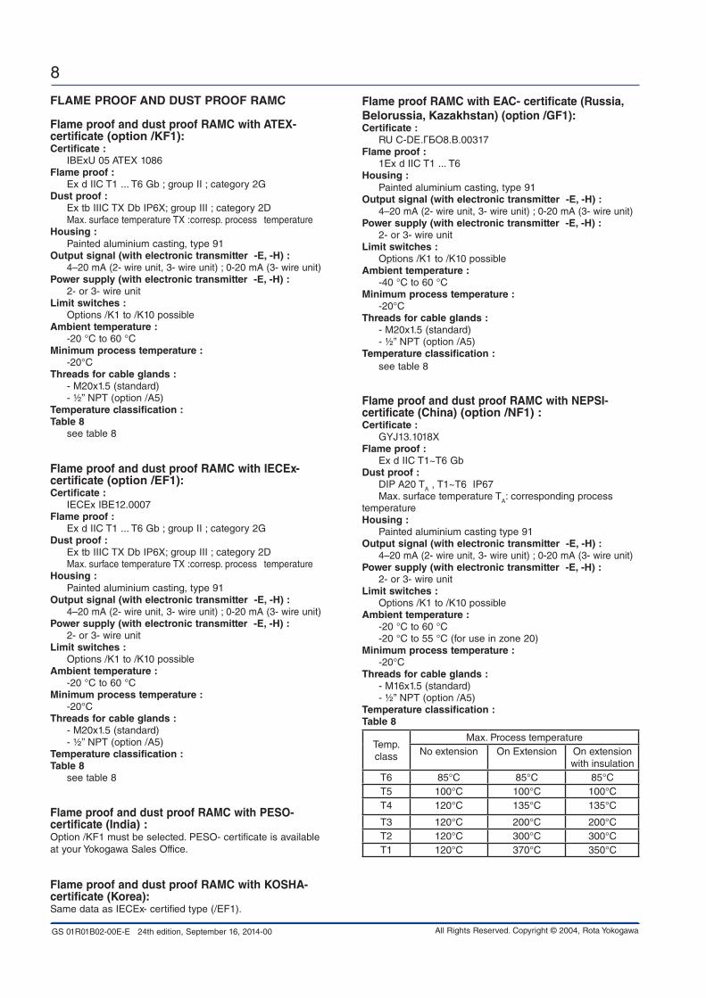
FLAME pRooF And dUST pRooF RAMC
Flame proof and dust proof RAMC with ATEX- certificate (option /KF1):Certificate : IBExU 05 ATEX 1086Flame proof : Ex d IIC T1 ... T6 Gb ; group II ; category 2Gdust proof : Ex tb IIIC TX Db IP6X; group III ; category 2D Max. surface temperature TX :corresp. process temperature Housing : Painted aluminium casting, type 91output signal (with electronic transmitter -E, -H) : 4–20 mA (2- wire unit, 3- wire unit) ; 0-20 mA (3- wire unit)power supply (with electronic transmitter -E, -H) : 2- or 3- wire unitLimit switches : Options /K1 to /K10 possibleAmbient temperature : -20 °C to 60 °C Minimum process temperature : -20°CThreads for cable glands : - M20x1.5 (standard) - ½” NPT (option /A5)Temperature classification :Table 8 see table 8
Flame proof and dust proof RAMC with iECEx- certificate (option /EF1):Certificate : IECEx IBE12.0007 Flame proof : Ex d IIC T1 ... T6 Gb ; group II ; category 2Gdust proof : Ex tb IIIC TX Db IP6X; group III ; category 2D Max. surface temperature TX :corresp. process temperature Housing : Painted aluminium casting, type 91output signal (with electronic transmitter -E, -H) : 4–20 mA (2- wire unit, 3- wire unit) ; 0-20 mA (3- wire unit)power supply (with electronic transmitter -E, -H) : 2- or 3- wire unitLimit switches : Options /K1 to /K10 possibleAmbient temperature : -20 °C to 60 °C Minimum process temperature : -20°CThreads for cable glands : - M20x1.5 (standard) - ½” NPT (option /A5)Temperature classification :Table 8 see table 8
Flame proof and dust proof RAMC with pESo- certificate (india) :Option /KF1 must be selected. PESO- certificate is available at your Yokogawa Sales Office.
Flame proof and dust proof RAMC with KoSHA- certificate (Korea):Same data as IECEx- certified type (/EF1).
Flame proof RAMC with EAC- certificate (Russia, belorussia, Kazakhstan) (option /GF1):Certificate : RU С-DЕ.ГБО8.В.00317Flame proof : 1Ex d IIC T1 ... T6 Housing : Painted aluminium casting, type 91output signal (with electronic transmitter -E, -H) : 4–20 mA (2- wire unit, 3- wire unit) ; 0-20 mA (3- wire unit)power supply (with electronic transmitter -E, -H) : 2- or 3- wire unitLimit switches : Options /K1 to /K10 possibleAmbient temperature : -40 °C to 60 °C Minimum process temperature : -20°CThreads for cable glands : - M20x1.5 (standard) - ½” NPT (option /A5)Temperature classification : see table 8
Flame proof and dust proof RAMC with nEpSi- certificate (China) (option /nF1) :Certificate : GYJ13.1018XFlame proof : Ex d IIC T1~T6 Gbdust proof : DIP A20 TA , T1~T6 IP67 Max. surface temperature TA: corresponding process temperature Housing : Painted aluminium casting type 91output signal (with electronic transmitter -E, -H) : 4–20 mA (2- wire unit, 3- wire unit) ; 0-20 mA (3- wire unit)power supply (with electronic transmitter -E, -H) : 2- or 3- wire unitLimit switches : Options /K1 to /K10 possibleAmbient temperature : -20 °C to 60 °C -20 °C to 55 °C (for use in zone 20)Minimum process temperature : -20°CThreads for cable glands : - M16x1.5 (standard) - ½” NPT (option /A5)Temperature classification :Table 8
Temp. class
Max. Process temperatureNo extension On Extension On extension
with insulationT6 85°C 85°C 85°CT5 100°C 100°C 100°CT4 120°C 135°C 135°C
T3 120°C 200°C 200°CT2 120°C 300°C 300°CT1 120°C 370°C 350°C

GS 01R01B02-00E-E 24th edition, September 16, 2014-00
9
All Rights Reserved. Copyright © 2004, Rota Yokogawa
inTRinSiC SAFE CoMponEnTS WiTH dUST-pRooF
ATEX- certified intrinsically safe electronic trans-mitter 4 - 20mA, with/without limit switches with dust proof RAMC (option /KS2):Certificate : PTB 12 ATEX2003 (Intrinsic safe electronic transmitter) PTB 99 ATEX2219X (Intrinsic safe limit switch SC3.5-N0) PTB 00 ATEX2049X (Intrinsic safe limit switch SJ 3.5-S.N) IBExU 05 ATEX1086 (Dust proof)output signal electronic transmitter: 4–20 mA (2-wire unit, 3-wire unit) ; 0-20mA (3-wire unit)Explosion proof : Ex ia IIC T6 Gb; group II ; category 2Gdust proof : Ex tb IIIC TX Db IP6X; group III ; category 2D Max. surface temperature TX : corresponding process temperature Entity parameter : see table 6 for electronic transmitter (/KS1) see certificates for limit switches Housing : Painted aluminium casting, type 91Ambient temperature : -20 °C to 60 °C Minimum process temperature : -20°CThreads for cable glands : - M20x1.5 (standard) - ½” NPT (option /A5)
iECEx- certified intrinsically safe electronic trans-mitter 4 - 20mA, with/without limit switches with dust proof RAMC (option /ES2):Certificate : IECEx PTB12.0020 (Intrinsic safe electronic transmitter) IECEx PTB11.0091 (Intrinsic safe limit switch SC3.5-N0) IECEx PTB11.0092 (Intrinsic safe limit switch SJ 3.5-S.N) IECEx IBE12.0007 (Dust proof)output signal electronic transmitter: 4–20 mA (2-wire unit, 3-wire unit) ; 0-20mA (3-wire unit)Explosion proof : Ex ia IIC T6 Gb; group II ; category 2Gdust proof : Ex tb IIIC TX Db IP6X; group II ; category 2D Max. surface temperature TX : corresponding process temperature Entity parameter : see table 6 for electronic transmitter (/KS1) see certificates for limit switches Housing : Painted aluminium casting, type 91Ambient temperature : -20 °C to 60 °C Minimum process temperature : -20°C Threads for cable glands : - M20x1.5 (standard) - ½” NPT (option /A5)
GS 01R01B02-00E-E 24th edition, September 16, 2014-00
10
All Rights Reserved. Copyright © 2004, Rota Yokogawa
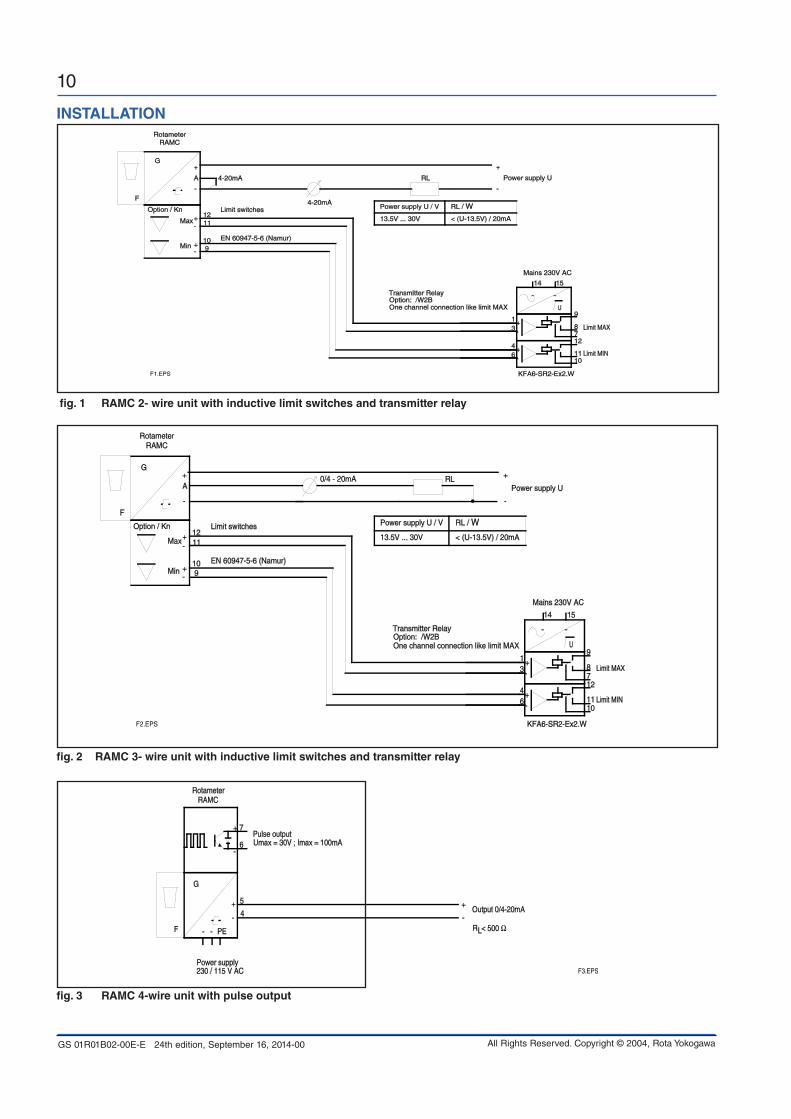
fig. 3 RAMC 4-wire unit with pulse output
F
G
RAMC
230 / 115 V AC
4
Power supply
Output 0/4-20mA
R < 500 ΩL
Rotameter
PE--
5
7
6Pulse outputUmax = 30V ; Imax = 100mA
-
+
-
+
+
-
F3.EPS
fig. 2 RAMC 3- wire unit with inductive limit switches and transmitter relay
15
46
31
14
12
1011
87
9U
F
G
RAMC
A Power supply U
Mains 230V AC
KFA6-SR2-Ex2.W
Option: /W2BTransmitter Relay
Limit MIN
Limit MAX
Option / Kn
Rotameter
Max
Min
1211
109
Limit switches
EN 60947-5-6 (Namur)
One channel connection like limit MAX
0/4 - 20mA RL
-
+
-
+
-+
-+
~ ~
+-
+-
Power supply U / V RL / W
13.5V ... 30V < (U-13.5V) / 20mA
F2.EPS
fig. 1 RAMC 2- wire unit with inductive limit switches and transmitter relay
15
46
31
14
12
1011
87
9U
F
G
RAMC
A Power supply U
Mains 230V AC
KFA6-SR2-Ex2.W
Option: /W2BTransmitter Relay
Limit MIN
Limit MAX
Option / Kn
Rotameter
4-20mA
Max
Min
1211
109
Limit switches
EN 60947-5-6 (Namur)
One channel connection like limit MAX
4-20mA
RL
-
+
-
+
-+
-+
~ ~
+-
+-
Power supply U / V RL / W
13.5V ... 30V < (U-13.5V) / 20mA
F1.EPS
inSTALLATion

GS 01R01B02-00E-E 24th edition, September 16, 2014-00
11
All Rights Reserved. Copyright © 2004, Rota Yokogawa
fig. 5 RAMC 2- wire unit with HART-communication, inductive limit switches and transmitter relay
15
46
31
14
12
1011
87
9U
F
G
RAMC
A Power supply U
Mains 230V AC
KFA6-SR2-Ex2.W
Option: /W2BTransmitter Relay
Limit MIN
Limit MAX
Option / Kn
Rotameter
4-20mA
Max
Min
1211
109
Limit switches
EN 60947-5-6 (Namur)
One channel connection like limit MAX
4-20mA
RL
HART-Communication
with HART-Communication
without HART-Communication
Power supply U/V RL/Ω
13.5V+(RL*20mA) ...30V
13.5V ... 30V < (U-13.5V) / 20mA
250 ... 500 Ω
-
+
-
+
-+
-+
~ ~
+-
+-
F4.EPS
fig. 4 intrinsic safe version according ATEX (option /KS1 or /KS2) : RAMC 2- wire unit with power supply, inductive limit switches and transmitter relay
15
46
31
14
12
1011
87
9
1211
109
I -
I +
L/+N/-O -O+
Output 4-20mA
O+H Output HART
U
F
G
RAMC
A
Supply 230V AC
KFA6-SR2-Ex2.W
Option: /W2B two channels: KFA6-SR2-Ex2.WTransmitter relay
Limit MIN
Limit MAX
Option / Kn
Rotameter
4-20mA
Max
Min
Limit switch
EN 60947-5-6 (Namur)
One channel connection like limit MAX
I = 101mAP = 1.4WC = 4.16nF
U = 30V
L = 0.15mH
WT - MAGEx ia IIC T6Gb
PTB 12ATEX2003Tumax = 70°C
Tamax = Temperature in indicator
C = 150nF
EEx ia IIC T6
L = 0.15uH
SC 3.5-NO
P = 64mWI = 25mAU = 16V
Temperature
T4 Tumax = 100°CT3 Tumax = 100°CT2 Tumax = 100°CT1 Tumax = 100°C
Class
T5 Tumax = 80°CT6 Tumax = 65°C
PTB 99 ATEX 2219 X
PTB 00 ATEX 2018
Transmitter power supply
Option: /UT
Option: /W2A one channel: KF A6-SR2-Ex1.W
C = 2320nF
I = 19,1mAP = 51mW
U = 10,6V
L = 97mH
PTB 00ATEX 2081
[EEx ia / ib]) IIC
KFA6-SR2-Ex2.W
RN221N-B1
RN221N-B1
Tamax = 50°C
C = 86nFL = 5.2mH
U = 27,3V
P = 0.597W
[Ex ia] IIC
I = 87,6mAo
oo
oo
-
+
-+
-+
~ ~
+-
+-
i
ii
i
iii
ii
o
o
o
oo
F5.EPS
i
Hazardous area Safe area

GS 01R01B02-00E-E 24th edition, September 16, 2014-00
12
All Rights Reserved. Copyright © 2004, Rota Yokogawa
planning and installation Hints
- The user is responsible for the use of our flow meters regarding suitability and use as agreed.
- The actual operation pressure must be lower as the specified pressure limits of the Rotameter.
- Make sure that the wetted parts are resistant against the process medium.
- Ambient- and process temperature must be lower than the specified maximum values.
- If dirt accumulation is to be expected, we recommend to install a bypass pipe
- To avoid float bouncing in case of gas application notice the recommendations of VDI/VDE 3513 Sheet 3.
- To avoid mutual magnetic influence in case of parallel design of several Rotameters take care that the distance between the tube middle axes is not less than 300 mm. The distance to other ferric materials should not be less than 250 mm.
- Avoid static magnetic fields next to the Rotameter.
+–
+–
Field Instrument
Field Instrument
Safe Area
Hazardous Area
Terminator
Safety Barrier
F91.EPS
RAMCxx-xxxx-xxxx-Gxx429 /KS1
Pro
fibus
PA
Pro
fibus
DP
Segment coupler
Grounding:1) Metering tube2) Cable shield on bus side3) Cable shield on transmitter side is recommended; if not done, restrictions of EMC immunity is possible (see specification).
3)2)
1)
fig. 6 RAMC profibus pA - communication

GS 01R01B02-00E-E 24th edition, September 16, 2014-00
13
All Rights Reserved. Copyright © 2004, Rota Yokogawa
ModEL SpECiFiCATionSModel Suffix code description Restrictions
RAMC01RAMC23RAMC02
RAMC03RAMC04RAMC05RAMC06
RAMC08RAMC09RAMC10RAMC12RAMC15RAMCNN
Size DN 15 (½ inch)Size DN 20 (¾ inch)Size DN 25 (1 inch)
Size DN 32 (1¼ inch)Size DN 40 (1½ inch)Size DN 50 (2 inch)Size DN 65 (2½ inch)
Size DN 80 (3 inch)3½ inchSize DN 100 (4 inch)Size DN 125 (5 inch)Size DN 150 (6 inch)Without measuring tube
for D4, D6, A1, A2, A3, T4, R4, T6, G6for D4, D6, A1, A2, A3, T4, R4, T6, G6for D4, D6, A1, A2, A3, S2, S4, S5, T4, R4, T6, G6for D4, D6, A1, A2, A3, S4, T6, G6for D4, D6, A1, A2, A3, S4, S5, T6, G6for D4, D5, D6, A1, A2, A3, S2, S4,T4, R4for D4, D5, A1, A2, A3, S2, S4, T4, R4, T6, G6for D4, D5, A1, A2, A3, S2, S4for A1, A2for D2, D4, A1, A2, S4, S4for D2, A1, A2, S2for D2, A1, A2
Process connection
-D2
-D4
-D5
-D6
-A1
-A2
-A3
-T6-G6-R4-S2-S4-T4-S5-NN
EN flange PN 16, process connection dimension + facing acc. EN 1092-1 Form B1EN flange PN 40, process connection dimension + facing acc. EN 1092-1 Form B1EN flange PN 63, process connection dimension + facing acc. EN 1092-1 Form B1EN flange PN 100, process connection dimen-sion + facing acc. EN 1092-1 Form B1ASME flange class 150, process connection dimension + facing acc. ASME B 16.5ASME flange class 300, process connection dimension + facing acc. ASME B 16.5ASME flange class 600, process connection dimension + facing acc. ASME B 16.5NPT PN 40 female thread G PN 40 female threadRp removable female threadThread acc. DIN 11851Tri- clamp PN 10, PN16 acc. DIN 32676NPT removable female threadFlange Rosista PN 10Without process connection
Material of wetted parts
SSPFNN
Stainless steelTeflon liningWithout wetted parts Only with RAMCNN
Cone / Float -nnnn-NNNN
See tables 10 ... 12Without measuring tube / without float Only with RAMCNN
Indicator / Transmitter -T-E-G-H-N
Indicator localIndicator electronicIndicator electronic with Profibus PAIndicator electronic with HART 5Without indicator
Only with output 429Only with output 424Only with housing NN
Housing / Type 9091NN
Housing round blanc; SSHousing round yellow; AlWithout housing Only with indicator N
Power supply / Output 240244140144430434424429NNN
230 V AC ; 4- wire; 0-20 mA230 V AC ; 4- wire; 4-20 mA115 V AC ; 4- wire; 0-20 mA115 V AC ; 4- wire; 4-20 mA24 V DC; 3- wire; 0-20 mA24 V DC; 3- wire; 4-20 mA24 V DC; 2- wire; 4-20 mAProfibus PA; 9 ... 32 V DCWithout power supply
Only with indicator E; not with limit switchesOnly with indicator E; not with limit switchesOnly with indicator E; not with limit switchesOnly with indicator E; not with limit switchesOnly with indicator EOnly with indicator E Only with indicator E, HOnly with indicator G; not with limit switchesOnly with indicator T or N

GS 01R01B02-00E-E 24th edition, September 16, 2014-00
14
All Rights Reserved. Copyright © 2004, Rota Yokogawa
opTionSoptions Code description Restriction
Indicator /A5/A12/A13/A14/A16/A17/A18/A20/A21/A22/A23
/A25
/A26
Thread for cable gland ASME ½´´ NPT femaleUS- engineering unitsThread for cable gland ISO M20 x 1,5 femaleHousing color greenIndicator on 95 mm extensionHousing color greenHousing color yellowScale for type T66Scale and EEPROM for type E66, H66, G66Scale for type T90, T91Scale and EEPROM for type E90, H90, G90, E91, H91, G91Pressure balance element
Indicator for -40°C ambient temperature
Not with /A13Only for indicator E, HNot with /A5, /KF1,/NF1, /KS2Only for housing 91Only for housing 90 + 91Only for housing 90Only for housing 90Not with hazardous approval type; not with indicatorNot with hazardous approval type not with indicatorNot with hazardous approval type; not with indicatorNot with hazardous approval type; not with indicator
Not with /KS2, /ES2, /KF1, /EF1, /NF1 and housing 91 with /A5 or /A13Not with /K1, /K2, /K3, /K9, /K10, /KF1, /EF1, /NF1, /KS2, /ES2, /FS1, /CS1, /NS1, power supply 14n + 24n.
Marking /B0/B1/BT1/BT2/B4/B8/B10/BG/BD
Tag plate (SS) on flange and marking on scaleTag plate (SS) fixed by wire and marking on scaleSoftware tag HART Software tag, bus address for Profibus PANeutral versionCustomer provided marking on labelPercent scaleCustomer specific notes on scaleDual scale
Plate 9 x 40 mm; max. 45 digitsPlate 9 x 40 mm; max. 45 digits8 digits for tag; 22 digits for long tag; only indicator H32 digits for tag; 4 digits bus address; only indicator GNot with hazardous approval type
Max. 45 digitsAdjustment only for the first mentioned fluid
Limit switches /K1/K2/K3/K6/K7/K8/K9/K10
MIN- contactMAX- contactMIN-MAX- contact, MIN-MIN- contact, MAX-MAX- contactMIN- contact “Fail safe” versionMAX- contact “Fail safe” versionMIN-MAX- contact “Fail safe” versionMIN-MIN- contact “Fail safe” versionMAX-MAX- contact “Fail safe” version
Not for power supply 14n + 24nNot for power supply 14n + 24nNot for power supply 14n + 24nNot for power supply 14n + 24nNot for power supply 14n + 24nNot for power supply 14n + 24nNot for power supply 14n + 24nNot for power supply 14n + 24n
Pulse output /CP Pulse output isolated Only for power supply 14n + 24n
Flange Facing /D10/D11
EN raised face B2 : Ra 0.8 - 3.2EN groove Form D
Only for EN- flanges (D2, D4)Only for EN- flanges (D2, D4)
Test and certificates /H1/H3/P2
/P3/P6/PM3
/PP/PT/P9
/P10/P11/P12/P13/WP
Oil + fat free for wetted surfaces acc. ASTM G93-03 level CCertificate pure water applicationCertificate of compliance with the order acc. EN 10204: 2004 -2.1As /P2 + Test report acc. EN 10204: 2004 -2.2Material certificate acc. EN 10204: 2004 -3.1PAMI test (3 points: Process connection inlet, measuring tube, process connection outlet)Pressure test report measuring systemFlow table for conversionDye Penetration test acc. DIN EN ISO 3452-1 at the welding of the process connection, with certificate
Combination of /P3 + /P6 + /PPCombination of /P3 + /P6 + /PM3Combination of /P3 + /P6 + /P9 + /PPCombination of /P3 + /P6 + /P9 + /PM3 + /PP + /WPWPS acc. DIN EN ISO 15609-1 (Welding Procedure Specification)WPQR acc. DIN EN ISO 15614-1 (Welder Performance Qualification Record)WQC acc. DIN EN 1418 (Welder Qualification Certificate), robot weldingWQC acc. DIN EN 287-1 (Welder Qualification Certificate), manual welding (SS)WQC acc. DIN EN ISO 6906-4 (Welder Qualification Certificate), manual welding (nickel alloy)
Only for metallic pressurized partsOnly for SS material of wetted parts
Only for SS- wetted part material; Not for connection RAMC01-T6SS-[][]S0-…, RAMC01-G6SS-[][]S0-…; not for /TxSee individual optionsSee individual optionsSee individual optionsSee individual optionsNot for connection RAMC01-T6SS-[][]S0-…, RAMC01-G6SS-[][]S0-…; not for /Tx
Damping /SD Float damping system Only for SS; not for cone 81 + 82; only for gas application

GS 01R01B02-00E-E 24th edition, September 16, 2014-00
15
All Rights Reserved. Copyright © 2004, Rota Yokogawa
options Code description Restriction
Flange protection /QK Flange covers Only for flanges A1, A2, A3, D2, D4, D5, D6
Delivery to Korea /KC With KC-mark for Korea
Eurasian Conformity /VE With EAC- mark
Hazardous area approvals
/KS1
/KS2
/KS3
/ES1
/ES2
/ES3/FS1
/CS1
/NS1
/GS1
/KF1
/EF1
/NF1
/GF1
ATEX intrinsically safe “ia”
ATEX intrinsically safe “ia” + dust proof “tb”
ATEX intrinsically safe “ic” for use in category 3G
IECEx intrinsically safe “ia”
IECEx intrinsically safe “ia” + dust proof “tb”
IECEx intrinsically safe “ic” FM intrinsically safe / non incendive electr. transmitter (USA)FM intrinsically safe / non incendive limit switches (USA)FM intrinsically safe / non incendive electronic transmitter (Canada), CSA intrinsically safe limit switches (Canada)
NEPSI intrinsically safe approval (China)
EAC intrinsically safe “ia”
ATEX flame proof “d” / dust proof “tb”
IECEx flame proof “d” / dust proof “tb”
NEPSI flame proof “d” / dust proof approval (China)
EAC flame proof “d”
Only for power supply 424, 430, 434, 429; for indicator T only with limit switchesOnly for power supply 424, 430, 434; for indicator T only with limit switches; only for housing 91Only for power supply 424, 430, 434; for indicator T only with limit switchesOnly for power supply 424, 430, 434; for indicator T only with limit switchesOnly for power supply 424, 430, 434; for indicator T only with limit switches; only for housing 91Only for power supply 424, 430, 434; not with limit switchesOnly for power supply 424 (electronic transmitter); for indicator T only with limit switchesOnly for power supply 424 (electronic transmitter); for indi-cator T only with limit switches (only /K1, /K2, /K3), only in combination with power supply /WxA or /WxBOnly for power supply 424, 430, 434; for indicator T only with limit switches; only housing 90Only for power supply 424, 430, 434; for indicator T only with limit switches; only with /VEOnly for power supply 424, 430, 434; for indicator T only with limit switches; only with housing 91Only for power supply 424, 430, 434; for indicator T only with limit switches; only with housing 91Only for power supply 424, 430, 434; for indicator T only with limit switches; only for housing 91Only for power supply 424, 430, 434; for indicator T only with limit switches; only for housing 91; only with /VE
Gost approval /QR1/QR2
/QR3
Primary Calibration and Test Confirmation valid in Russia Primary Calibration and Test Confirmation valid in Kazakhstan Primary Calibration and Test Confirmation valid in Uzbekistan
See page 4; only with /VESee page 4; only with /VE
See page 4
Heat tracing /T1
/T2/T3/T4/T5/T6
Heat tracing, process connection G ¼`` PN 40 female threadHeat tracing, process connection DN 15 PN 40Heat tracing, process connection DN 25 PN 40Heat tracing, process connection ASME ½´´ 150#Heat tracing, process connection ASME 1´´ 150#Heat tracing, process connection ¼´´ PN 40 NPT female thread
Only for SS material of wetted parts
Only for SS material of wetted partsOnly for SS material of wetted partsOnly for SS material of wetted partsOnly for SS material of wetted partsOnly for SS material of wetted parts
Power supply forelectronic transmitter
/UT RN221N-B1, 20 ... 250V DC/AC, Ex i, Hart compatible Only for indicator E, H
Power supply for limit switches (transmitter relay)
/W1A/W1B/W2A/W2B/W2E/W2F/W4A/W4B/W4E/W4F
KFA5-SR2-Ex1.W / 115 V AC, 1 channelKFA5-SR2-Ex2.W / 115 V AC, 2 channelKFA6-SR2-Ex1.W / 230 V AC, 1 channelKFA6-SR2-Ex2.W / 230 V AC, 2 channelKHA6-SH-Ex1 / 115/230 V AC, 1 channel, Fail Safe2x KHA6-SH-Ex1 / 115/230 V AC, 1 channel, Fail SafeKFD2-SR2-Ex1.W / 24 V DC, 1 channelKFD2-SR2-Ex2.W / 24 V DC, 2 channelKFD2-SH-Ex1 / 24 V DC, 1 channel, Fail Safe2x KFD2-SH-Ex1 / 24 V DC, 1 channel, Fail Safe
Only for limit switches /K1, /K2, /K3 Only for limit switches /K1, /K2, /K3Only for limit switches /K1, /K2, /K3Only for limit switches /K1, /K2, /K3Only for limit switches /K6 to /K7Only for limit switches /K8 to /K10Only for limit switches /K1, /K2, /K3Only for limit switches /K1, /K2, /K3Only for limit switches /K6 to /K7Only for limit switches /K8 to /K10
Instruction manuals /IEn/IDn/IFn
Quantity of instruction manuals in EnglishQuantity of instruction manuals in GermanQuantity of instruction manuals in French
n = 1 to 9 selectable *)n = 1 to 9 selectable *)n = 1 to 9 selectable *)
Special order /Z Special design must be specified separately
*) if no instruction manual is selected, only a DVD with instruction manuals is shipped with the flowmeter
Specify the following when ordering :1) Model, suffix code and option code 2) Fluid name ; Process temperature ; Process density ; Process pressure ; Process viscosity 3) For gases : Condition of the scale (st. or actual) 4) Options : Tag No. ; Customer specific notes
GS 01R01B02-00E-E 24th edition, September 16, 2014-00
16
All Rights Reserved. Copyright © 2004, Rota Yokogawa
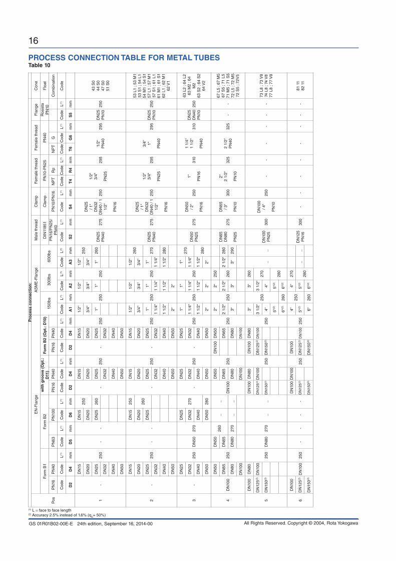
pRoCESS ConnECTion TAbLE FoR METAL TUbESTable 10
pro
cess
co
nn
ecti
on
:
Pos
EN
-Fla
nge
AS
ME
-Fla
nge
Mal
e th
read
Cla
mp
Fem
ale
thre
ad
Fem
ale
thre
adF
lang
eC
one
For
m B
1F
orm
B2
wit
h g
roov
e (o
pt.
: d
11)
Form
b2
(op
t.: d
10)
150l
bs30
0lbs
600l
bsD
IN11
851
Cla
mp
PN
10-P
N25
PN
40R
osis
ta
PN
10F
loat
PN
16P
N40
PN
63P
N10
0P
N16
PN
40P
N16
PN
40P
N16
/PN
25/
PN
40P
N10
/PN
16N
PT
Rp
NP
TG
Com
bina
tion
Cod
eC
ode
L(1)
Cod
eL(1
) C
ode
L(1)
Cod
eC
ode
L(1)
Cod
eC
ode
L(1)
Cod
eL(1
) C
ode
L(1)
Cod
eL(1
) C
ode
L(1)
Cod
eL(1
) C
ode
Cod
eL(1
) C
ode
Cod
eL(1
) C
ode
L(1)
Cod
e
d2
d4
mm
d5
mm
d6
mm
d2
d4
mm
d2
d4
mm
A1
mm
A2
mm
A3
mm
S2
mm
S4
mm
T4
R4
mm
T6
G6
mm
S5
mm
1-
DN
15
250
--
DN
1525
0
-
DN
15
250
-
DN
15
250
1/2“
250
1/2“
250
1/2“
250
DN
25
PN
4027
5
DN
25
/ 1“
DN
32
DN
40 /
1 1/
2“
P
N16
250
1/2“
3/
4“
P
N25
29
51/
2“
PN
4029
5D
N25
P
N10
250
43 S
0 44
S0
47 S
0 51
S0
DN
20D
N20
DN
20D
N20
3/4“
3/4“
3/4“
DN
25D
N25
260
DN
25D
N25
1“1“
1“26
0
DN
32D
N32
DN
32
DN
40D
N40
DN
40
DN
50D
N50
DN
50
2-
DN
15
250
--
DN
1525
0
-
DN
15
250
-
DN
15
250
1/2“
250
1/2“
250
1/2“
260
DN
25
PN
4027
5
DN
25
/ 1“
DN
32
DN
40 /
1 1/
2“
P
N16
250
1/2“
3/
4“
P
N25
295
3/4“
1“
PN
40
295
DN
25
PN
1025
0
53 L
1 ; 5
3 M
1 53
S1
; 54
L1
54 M
1 ; 5
4 S
1 57
L1
; 57
M1
57 S
1 ; 6
1 L1
61
M1
; 61
S1
62 L
1 ; 6
2 M
1 62
V1
DN
20D
N20
260
DN
20D
N20
3/4“
3/4“
3/4“
DN
25D
N25
DN
25D
N25
1“1“
1“27
0D
N32
DN
32D
N32
1 1/
4“1
1/4“
1 1/
4“
DN
40D
N40
DN
401
1/2“
1 1/
2“1
1/2“
280
DN
50D
N50
DN
502“
2“
3-
DN
25
250
DN
5027
0
DN
25
270
-
DN
25
250
-
DN
25
250
1“
250
1“
250
1“27
0
DN
50
PN
2527
5
DN
50
/ 2“
PN
16
250
1“
P
N16
310
1 1/
4“
1 1/
2“
P
N40
310
DN
25
DN
40
PN
1025
0
63 L
2 ; 6
4 L2
63
M2
; 64
M2
63 S
2 ; 6
4 S
2 64
V2
DN
32D
N32
DN
32D
N32
1 1/
4“1
1/4“
1 1/
4“
DN
40D
N40
DN
40D
N40
1 1/
2“1
1/2“
1 1/
2“28
0D
N50
DN
5028
0D
N50
DN
502“
2“2“
4D
N10
0
DN
50
250
DN
5026
0_
_
DN
100
DN
50
250
DN
100
DN
50
250
2“
250
2“25
0D
N65
D
N80
PN
25
275
DN
65
/ 3“
PN
10
300
2“
2 1/
2“
P
N10
325
2 1/
2“
PN
4032
5-
-
67 L
5 ; 6
7 M
5 67
S5
; 71
L5
71 M
5 ; 7
1 S
5 72
L5
; 72
M5
72 S
5 ; 7
2V5
DN
65D
N65
DN
65D
N65
2 1/
2“2
1/2“
260
2 1/
2“28
0
DN
80D
N80
270
__
DN
80D
N80
3“3“
3“29
0
DN
100
DN
100
DN
100
5
DN
100
DN
80
250
DN
8027
0_
_
DN
100
DN
80
250
DN
100
DN
80
250
3“
250
3“26
0
__
DN
100
PN
2530
0
DN
100
/ 4“
PN
10
250
--
--
--
73 L
8 ; 7
3 V
8 74
L8
; 74
V8
77 L
8 ; 7
7 V
8
DN
125(2
)D
N10
0D
N12
5(2)D
N10
0D
N12
5(2)D
N10
03
1/2“
3 1/
2“27
0D
N15
0(2)
DN
150(2
)D
N15
0(2)
4“4“
5“(2
)5“
(2)
280
6“(2
)26
06“
(2)
6
DN
100
DN
100
250
--
--
DN
100
DN
100
250
DN
100
DN
100
250
4“25
04“
270
DN
125
PN
1630
0-
--
--
--
-81
11
82 1
1D
N12
5(2)
DN
125(2
)D
N12
5(2)
5“(2
)5“
(2)
280
__
DN
150(2
)D
N15
0(2)
DN
150(2
)6“
260
6“(2
)
(1) L = face to face length(2) Accuracy 2.5% instead of 1.6% (qG= 50%)

GS 01R01B02-00E-E 24th edition, September 16, 2014-00
17
All Rights Reserved. Copyright © 2004, Rota Yokogawa
FLoW TAbLES FoR METAL TUbESTable 11
Pos
.
Mea
suri
ng
ran
ge
for
wat
er a
nd
liq
uid
sM
easu
rin
g r
ang
e fo
r ai
r an
d g
ases
Rec
om
men
ded
co
mb
inat
ion
Alt
ern
ativ
e co
mb
inat
ion
Rec
om
men
ded
co
mb
inat
ion
Alt
ern
ativ
e co
mb
inat
ion
Max
. flo
w
Co
ne-
pre
ssu
reC
on
e-p
ress
ure
Max
. flo
w
Co
ne-
pre
ssu
reC
on
e-p
ress
ure
Flo
at-
com
bin
.lo
ss a)
vis
cosi
ty
b)
Flo
at-
com
bin
.lo
ss a)
vis
cosi
ty b
)F
loat
-co
mb
in.
loss
a)F
loat
-co
mb
in.
loss
a)
m3 /
h c)
gp
m d
)C
od
em
bar
mp
a*s
Co
de
mb
arm
pa*
sm
3 /h
c)
m3 /
h i
.n. e
)sc
fm f)
Co
de
mb
arC
od
em
bar
1
0.02
50.
1143
S0
4010
--
-0.
750
0.44
43 S
045
--
0.04
0.18
44 S
040
80-
--
1.2
1.1
0.7
44 S
045
--
0.06
30.
2847
S0
4080
--
-1.
81.
71.
0547
S0
45-
-
0.1
0.44
51 S
040
80-
--
32.
81.
7551
S0
45-
-
2
0.13
0.57
53 L
112
50-
--
43.
62.
353
L1
13-
-
0.16
0.7
--
-53
M1
1510
05.
55
3.2
--
53 M
121
0.22
1.0
54 L
112
50-
--
--
--
--
0.25
1.1
53 S
140
100
54 M
115
506.
56
3.8
54L
113
--
0.32
1.4
--
-57
L1
1250
98.
55
--
54 M
121
0.4
1.8
54 S
140
5057
M1
1550
109
5.7
57 L
113
-v
0.5
2.2
--
-61
L1
1250
1413
8-
-57
M1
21
0.63
2.8
57 S
140
5061
M1
1510
016
159
61 L
113
--
0.8
3.5
--
-62
L1
1250
2220
12-
-61
M1
21
1.0
4.4
61 S
140
100
62 M
115
100
2523
1462
L1
13-
-
1.6
7.0
62 S
140
100
--
-34
3220
--
62 M
121
2.2
10.1
--
-62
v1
4550
5045
28-
-62
S1
45
3
1.3
5.7
63 L
217
50-
--
4036
2363
L2
19-
-
2.1
9.2
--
-64
L2
1750
5047
29-
-63
M2
23
2.5
11.0
63 S
242
3064
M2
1710
6055
3564
L2
19-
-
417
.664
S2
4210
--
-85
8050
--
64 M
223
626
.4-
--
64 v
243
5012
011
070
--
64 S
247
4
3.2
1467
L5
1350
--
-10
090
5767
L5
16-
-
5.0
22-
--
71 L
513
5013
012
075
--
67 M
525
6.3
2867
S5
4730
--
-16
015
090
71 L
516
--
8.5
37-
--
72 L
513
5020
018
011
5-
-71
M5
25
1044
71 S
547
572
M5
195
250
230
140
72 L
516
--
1670
72 S
547
5-
--
340
320
200
--
72 m
525
2511
0-
--
72 v
563
550
047
029
0-
-72
S5
54
5
2511
073
v8
6010
--
-55
050
032
073
L8
30-
-
4017
674
v8
6010
--
-85
080
050
074
L8
30-
-
6327
777
v8
6010
--
-14
00
130
080
077
L8
30-
-
610
044
081
11
7010
--
--
--
--
--
130
572
82 1
170
10-
--
--
--
--
-
a) Pressure loss at the float with water or air. b) For higher viscosity the specified precision is no more guaranteed. c) Flow is referred to 20°C and 1 bar abs .d) Flow in US Gallons per minute at 70°F .e) Flow referred to 0°C and 1.013 bar abs at operation conditions of 20°C and 1,013 bar abs.f) Flow in Standard cubic feet per minute referred to 60°F and 14,7 PSI at operation conditions of 70°F und 14,7 PSI abs.
For your special application please use the Rota Yokogawa Sizing-Program.

GS 01R01B02-00E-E 24th edition, September 16, 2014-00
18
All Rights Reserved. Copyright © 2004, Rota Yokogawa
pRoCESS ConnECTion- And FLoW-TAbLE FoR TUbES WiTH pTFE LininGTable 12
po
s.
pro
cess
co
nn
ecti
on
M
easu
rin
g r
ang
e fo
r w
ater
an
d li
qu
ids
Mea
suri
ng
ran
ge
for
air
and
gas
es
En
-Fla
ng
eA
SM
E-F
lan
ge
Max
. Flo
w
Co
ne-
pre
ssu
re
Max
. Flo
w
Co
ne-
pre
ssu
re
pn
16
pn
40L
(1)
150
lbs
300
lbs
Flo
at-
loss
a)v
isco
Flo
at-
loss
a)
Co
de
Co
de
Co
de
L(1
)C
od
eL
(1)
com
bin
atio
nsi
ty b
)co
mb
inat
ion
d2
d4
mm
A1
mm
A2
mm
m3 /
h c)
gp
m d
)C
od
em
bar
mp
a*s
m3 /
h c
)m
3 /h
i.n
. e)sc
fm f
)C
od
em
bar
2-
250
250
¾“
1“
250
0.1
0.45
51 A
116
503.
53.
32
51 A
120
0.16
0.7
52 A
116
505
4.7
2.9
52 A
120
DN
15
¾“
0.25
1.12
53 A
116
508.
58
553
A1
20
DN
25
1“0.
41.
854
A1
1650
1312
7.5
54 A
120
0.63
2.8
57 A
116
5020
1811
57 A
120
14.
561
V1
1850
3432
2061
V1
22
3-
DN
25
250
1¼“
1½“
250
1¼“
1½“
250
1.6
762
A2
2030
5047
2962
A2
25
DN
40
2.5
11.2
63 A
220
1085
8050
63 A
225
DN
50
418
63 V
222
50-
--
--
4-
DN
50
DN
65
D
N80
25
02½
“
3“
260
2½“
3“27
0
418
64 A
520
3013
012
075
64 A
525
6.3
2867
A5
2030
200
180
115
67 A
525
1045
71 A
520
535
033
020
071
A5
25
1670
71 V
522
10-
--
--
5 D
N10
025
03½
“
4“
270
3½“
4“27
0
1670
72 V
825
1050
047
029
072
V8
27
DN
8025
110
73 V
825
1085
080
050
073
V8
27
4018
074
V8
2510
--
--
-
6D
N10
0D
N10
025
04“
270
4“27
063
280
77 1
030
10-
--
--
(1) L = Mounting length a) Pressure loss at the float with water or air. b) As from this viscosity the specified precision is no more guaranteed. c) Flow is referred to 20°C and 1 bar abs. d) Flow in US Gallons per minute at 70°F. e) Flow referred to 0°C and 1.013 bar abs at operation conditions of 20°C and 1,013 bar abs. f) Flow in Standard cubic feet per minute referred to 60°F and 14,7 PSI at operation conditions of 70°F und 14,7 PSI abs.
For your special application please use the Rota Yokogawa Sizing-Program.

GS 01R01B02-00E-E 24th edition, September 16, 2014-00
19
All Rights Reserved. Copyright © 2004, Rota Yokogawa
TEMpERATURE GRApHS FoR RAMC METAL dESiGn, STAndARd And inTRinSiC SAFE
The temperature graphs are reference values for size DN100. They may be influenced negative by trapped heat, external heat sources or radiated heat and influenced positive for smaller sizes.Insulation means rock wool between tube and indicator.Units with electronic transmitter can show the temperature of the internal transmitter on the display or HART- type can show and supervise the internal temperature by HART-communication.Units with PTFE lining are usable up to 130°C.For units with explosion proof certification the temperature limits according the certificate of conformity must be regarded (see also page 4 to 6).
T10.EPS
0
50
100
150
200
250
300
350
400
20 30 40 50 60 70 80 90
Ambient temperature [°C]
max
pro
cess
tem
pera
ture
[°C]
without option /A16with option /A16 and insulationwith option /A16, no insulation
050
100
150200250300
350400
20 30 40 50 60 70
Ambient temperature [°C]
max
pro
cess
tem
pera
ture
[°C]
without option /A16with option /A16 and insulationwith option /A16, no insulation
-200
-150
-100
-50
0
-30 -20 -10 0
Ambient temperature [°C]
min
pro
cess
tem
pera
ture
[°C]
Low temperature curvewith option /A16 and insulation
fig. 7a RAMC : - type 90 / 91 - only with indicator
fig. 7b RAMC : - type 90 / 91 - with limit switches - with electronic transmitter
fig. 7c RAMC : - type 90 / 91 - with or without limit switches - with or without electronic transmitter
-40

GS 01R01B02-00E-E 24th edition, September 16, 2014-00
20
All Rights Reserved. Copyright © 2004, Rota Yokogawa
MiniMUM AMbiEnT TEMpERATURESFlow meter Model code Minimum ambient temperature
RAMC with local indicator RAMCxx-xxxx-xxxx-TxxNNN -25°C; -40°C with option /A26 *)
RAMC with standard limit switches RAMCxx-xxxx-xxxx-xxxxxx /K1.../K3 -25°CRAMC with fail safe limit switches /K6.../K8 RAMCxx-xxxx-xxxx-xxxxxx /K6.../K8 -25°C; -40°C with option /A26 *) RAMC with fail safe limit switches /K9.../K10 RAMCxx-xxxx-xxxx-xxxxxx /K9.../K10 -25°C
RAMC with electronic transmitter
RAMCxx-xxxx-xxxx-Exx1xxRAMCxx-xxxx-xxxx-Exx2xxRAMCxx-xxxx-xxxx-Exx4xxRAMCxx-xxxx-xxxx-Hxx4xx
-25°C-25°C
-25°C; -40°C with option /A26 *) -25°C; -40°C with option /A26 *)
RAMC with electronic transmitter PA RAMCxx-xxxx-xxxx-Gxx429 -25°C
RAMC intrinsic safe type
RAMCxx-xxxx-xxxx-xxxxxx /KS1RAMCxx-xxxx-xxxx-xxxxxx /KS1 /K1.../K3RAMCxx-xxxx-xxxx-xxxxxx /KS1 /K6.../K8RAMCxx-xxxx-xxxx-xxxxxx /KS1 /K9.../K10RAMCxx-xxxx-xxxx-xxxxxx /KS3RAMCxx-xxxx-xxxx-xxxxxx /KS3 /K1.../K3RAMCxx-xxxx-xxxx-xxxxxx /KS3 /K6.../K8RAMCxx-xxxx-xxxx-xxxxxx /KS3 /K9.../K10RAMCxx-xxxx-xxxx-xxxxxx /KN1RAMCxx-xxxx-xxxx-xxxxxx /KN1 /K1.../K3RAMCxx-xxxx-xxxx-xxxxxx /KN1 /K6.../K8RAMCxx-xxxx-xxxx-xxxxxx /KN1 /K9.../K10RAMCxx-xxxx-xxxx-xxxxxx /ES1RAMCxx-xxxx-xxxx-xxxxxx /ES1 /K1.../K3RAMCxx-xxxx-xxxx-xxxxxx /ES1 /K6.../K8RAMCxx-xxxx-xxxx-xxxxxx /ES1 /K9.../K10RAMCxx-xxxx-xxxx-xxxxxx /ES3RAMCxx-xxxx-xxxx-xxxxxx /FS1 /....RAMCxx-xxxx-xxxx-xxxxxx /CS1 /....RAMCxx-xxxx-xxxx-xxxxxx /NS1 /....
-25°C; -40°C with option /A26 *)-25°C
-25°C; -40°C with option /A26 *)-25°C
-25°C; -40°C with option /A26 *)-25°C
-25°C; -40°C with option /A26 *)-25°C
-25°C; -40°C with option /A26 *)-25°C
-25°C; -40°C with option /A26 *)-25°C
-25°C; -40°C with option /A26 *)-25°C;
-25°C; -40°C with option /A26 *)-25°C
-25°C; -40°C with option /A26 *)-25°C-25°C-25°C
RAMC flame proof or dust proof type
RAMCxx-xxxx-xxxx-xxxxxx /KF1 /....RAMCxx-xxxx-xxxx-xxxxxx /EF1 /....RAMCxx-xxxx-xxxx-xxxxxx /NF1 /....RAMCxx-xxxx-xxxx-xxxxxx /KS2 /....RAMCxx-xxxx-xxxx-xxxxxx /ES2 /....
-20°C
RAMC flame proof type RAMCxx-xxxx-xxxx-xxxxxx /GF1 /.... -40°C
*) Below -25°C the LC-display will not work. Also the push buttons should not be used below -25°C !

GS 01R01B02-00E-E 24th edition, September 16, 2014-00
21
All Rights Reserved. Copyright © 2004, Rota Yokogawa
pRESSURE RATinG
The pressure relevant temperature limits of the RAMC are: -200 to 370°C for units with SS wetted parts -80 to 130°C for units with PTFE wetted parts.These limits are reduced by metrological boundary conditions (see temperature curves and table).
process connectionProcess temperature
-200°CRT
(20°C)50°C 100°C 150°C 200°C 250°C 300°C 350°C 370°C
A1 *) Flange ASME 150lbs 19 bar 19 bar 18.4 bar 16.2 bar 14.8 bar 13.7 bar 12.1 bar 10.2 bar 8.4 bar 7.4 bar
A2 *) Flange ASME 300lbs 49.6 bar 49.6 bar 48.1 bar 42.2 bar 38.5 bar 35.7 bar 33.4 bar 31.6 bar 30.3 bar 29.9 bar
A3 *) Flange ASME 600lbs 99.3 bar 99.3 bar 96.2 bar 84.4 bar 77 bar 71.3 bar 66.8 bar 63.2 bar 60.7 bar 59.8 bar
D2 Flange EN PN16 16 bar 16 bar 15.6 bar 14.2 bar 12.8 bar 11.7 bar 10.9 bar 10.3 bar 9.9 bar 9.6 bar
D4 Flange EN PN40 40 bar 40 bar 39.1 bar 35.6 bar 32 bar 29.3 bar 27.2 bar 25.8 bar 24.7 bar 24 bar
D5 Flange EN PN63 63 bar 63 bar 61.6 bar 56 bar 50.4 bar 46.2 bar 42.8 bar 40.6 bar 38.9 bar 37.8 bar
D6 Flange EN PN100 100 bar 100 bar 97.8 bar 88.9 bar 80 bar 73.3 bar 68 bar 64.4 bar 61.8 bar 60 bar
R4/T4 Internal Thread RAMC01.. 25 bar 25 bar 25 bar 25 bar 20 bar 20 bar 20 bar 20 bar ------- -------
R4/T4 Internal Thread RAMC23.. 25 bar 25 bar 25 bar 25 bar 20 bar 20 bar 20 bar 20 bar ------- -------
R4/T4 Internal Thread RAMC02.. 16 bar 16 bar 16 bar 16 bar 16 bar 16 bar 16 bar 16 bar ------- -------
R4/T4 Internal Thread RAMC03.. 16 bar 16 bar 16 bar 16 bar 16 bar 16 bar 16 bar 16 bar ------- -------
R4/T4 Internal Thread RAMC05.. 10 bar 10 bar 10 bar 10 bar 10 bar 10 bar 10 bar 10 bar ------- -------
R4/T4 Internal Thread RAMC06.. 10 bar 10 bar 10 bar 10 bar 10 bar 10 bar 10 bar 10 bar ------- -------
G6/T6 Internal Thread RAMC01.. 40 bar 40 bar 40 bar 40 bar 40 bar 40 bar 40 bar 40 bar ------- -------
G6/T6 Internal Thread RAMC23.. 40 bar 40 bar 40 bar 40 bar 40 bar 40 bar 40 bar 40 bar ------- -------
G6/T6 Internal Thread RAMC02.. 40 bar 40 bar 40 bar 40 bar 40 bar 40 bar 40 bar 40 bar ------- -------
G6/T6 Internal Thread RAMC03.. 40 bar 40 bar 40 bar 40 bar 40 bar 40 bar 40 bar 40 bar ------- -------
G6/T6 Internal Thread RAMC06.. 40 bar 40 bar 40 bar 40 bar 40 bar 40 bar 40 bar 40 bar ------- -------
Process temperature
-200°CRT
(20°C)50°C 100°C 140°C
see corresponding standard for the connection
S2 Clamp DIN 11851 RAMC02.. 40 bar 40 bar 40 bar 40 bar
S2 Clamp DIN 11851 RAMC05.. 25 bar 25 bar 25 bar 25 bar
S2 Clamp DIN 11851 RAMC06.. 25 bar 25 bar 25 bar 25 bar
S2 Clamp DIN 11851 RAMC08.. 25 bar 25 bar 25 bar 25 bar
S2 Clamp DIN 11851 RAMC10.. 25 bar 25 bar 25 bar 25 bar
S2 Clamp DIN 11851 RAMC12.. 16 bar 16 bar 16 bar 16 bar
Process temperature
-200°CRT
(20°C)50°C 100°C 150°C
see corresponding standard for the connection
S4 Tri- Clamp DIN 32676 RAMC02.. 16 bar 16 bar 16 bar 16 bar
S4 Tri- Clamp DIN 32676 RAMC03.. 16 bar 16 bar 16 bar 16 bar
S4 Tri- Clamp DIN 32676 RAMC04.. 16 bar 16 bar 16 bar 16 bar
S4 Tri- Clamp DIN 32676 RAMC05.. 16 bar 16 bar 16 bar 16 bar
S4 Tri- Clamp DIN 32676 RAMC06.. 10 bar 10 bar 10 bar 10 bar
S4 Tri- Clamp DIN 32676 RAMC08.. 10 bar 10 bar 10 bar 10 bar
S4 Tri- Clamp DIN 32676 RAMC10.. 10 bar 10 bar 10 bar 10 bar
S5 Rosista Flange RAMC02.. 10 barsee corresponding standard for the connection
S5 Rosista Flange AMC04.. 10 bar
*) Dual certified AISI 316/316L

GS 01R01B02-00E-E 24th edition, September 16, 2014-00
22
All Rights Reserved. Copyright © 2004, Rota Yokogawa
diMEnSionS And WEiGHTS
fig. 8a Front view housing type 90 fig. 8b Front view housing type 91
T12.EPS
fig. 9 Metal version fig. 10 Metal version with liningT14.EPS
a
b
T15.EPS
a
b
amm
bmm
Housing type 90 104 161
Housing type 91 standard 110 165
Housing type 91 flame proof , option /KF1 118 165

GS 01R01B02-00E-E 24th edition, September 16, 2014-00
23
All Rights Reserved. Copyright © 2004, Rota Yokogawa
Table 13
Inner diameter of stainless steel flanges Inner diameter of flanges with PTFE- lining
Pos. *)
EN-flange without groove ASME-flange Rosita- flange
Pos. *)
EN- flange ASME-flage
SizeDumm
Domm
SizeDumm
Domm
Du=Domm
Size SizeDu = Do
mm
1 DN15-DN50 20.7 20.7 ½´´ - 1´´ 20.7 20.7 20.7 ---- ---- ---- ----
2DN15-DN50 29.5 29.5
½´´ 20.7 20.729.5 2 DN15-DN25 ¾´´ - 1´´ 23.5
¾´´ - 2´´ 29.5 29.5
3DN25-DN50 45.2 45.2
1´´ 32.2 32.245.2 3 DN25-DN50 1¼´´ - 1½ 36.0
1¼´ - 2´´ 45.2 45.2
4DN50-DN100 62.0 76.0
2´´ 62.0 65.5----- 4 DN50-DN80 2½´´ - 3´´ 66.0
2½´´ - 3´´ 62.0 76.0
5 DN80-DN150 94.0 94.0 3´´ - 6´´ 94.0 94.0 ----- 5 DN80-DN100 3½´´ - 4´´ 82.0
6 DN100-DN150 116.0 116.0 4´´ - 6´´ 116.0 116.0 ----- 6 DN100 4´´ 110.0
*) see table 10, 11, 12
fig. 11 RAMC type 91 and option /A16 and T2 fig. 12 RAMC with connection R4/ T4
T25.EPS
T26.EPS

GS 01R01B02-00E-E 24th edition, September 16, 2014-00
24
All Rights Reserved. Copyright © 2004, Rota Yokogawa
fig. 13 RAMC with connection T6/ G6 fig. 14 RAMC with connection S2
T19.EPST18.EPS
Table 14 diameter for connection sizes S4
Position *)
Size [mm] di [mm] da [mm]
1
DN25 / 1´´ 36 50.5
DN32 36 50.5
DN40 / 1 ½ ´´ 36 50.5
2
DN25 / 1´´ 36 50.5
DN32 36 50.5
DN40 / 1 ½ ´´ 36 50.5
3 DN50 / 2´´ 47.8 64
4 DN65 / 3´´ 72.1 91
5 DN100 / 4´´ 97.6 119
*) see table 10, 11, 12
Table 15 Weights
Position *) Weight [kg]
1 3 - 5
2 3 - 5
3 6.5 - 8
4 8.6 - 11
5 13 - 16
6 17 - 20
*) see table 10, 11, 12
Indicator on distance (option /A16) additional 1kgT20.EPS
fig. 15 RAMC with connection S4

GS 01R01B02-00E-E 24th edition, September 16, 2014-00
25
All Rights Reserved. Copyright © 2004, Rota Yokogawa

GS 01R01B02-00E-E 24th edition, September 16, 2014-00
26
All Rights Reserved. Copyright © 2004, Rota Yokogawa

GS 01R01B02-00E-E 24th edition, September 16, 2014-00
27
All Rights Reserved. Copyright © 2004, Rota Yokogawa

GS 01R01B02-00E-E 24th edition, September 16, 2014-00
28
All Rights Reserved. Copyright © 2004, Rota Yokogawa
Yokogawa has an extensive sales and distribution network. Please refer to the European website (www.yokogawa.com/eu) to contact your nearest representative.
Euroweg 23825 HD AMERSFOORTThe Netherlandswww.yokogawa.com/eu
YOKOGAWA ELECTRIC CORPORATIONWorld Headquarters9-32, Nakacho 2-chome, Musashino-shiTokyo 180-8750Japanwww.yokogawa.com
YOKOGAWA CORPORATION OF AMERICA2 Dart RoadNewnan GA 30265USAwww.yokogawa.com/us
YOKOGAWA ELECTRIC ASIA Pte. LTD.5 Bedok South RoadSingapore 469270Singaporewww.yokogawa.com/sg
YOKOGAWA CHINA CO. LTD.3F Tower D Cartelo Crocodile BuildingNo.568 West Tianshan Road Changing DistrictShanghai, Chinawww.yokogawa.com/cn
YOKOGAWA MIDDLE EAST B.S.C.(c)P.O. Box 10070, ManamaBuilding 577, Road 2516, Busaiteen 225Muharraq, Bahrainwww.yokogawa.com/bh
RotameterTM is a trademark of Rota Yokogawa GmbH & Co. KG, a subsidiary of Yokogawa Electric Corporation, Japan. In the United Kingdom RotameterTM is a trademark of Emerson Electric Co.
Subject to change without notice
Related Documents