Page 1 HBX Control Systems Inc. ECO-1000 Central Processing Unit 1000 Version 1.33 General Installation Guide

Welcome message from author
This document is posted to help you gain knowledge. Please leave a comment to let me know what you think about it! Share it to your friends and learn new things together.
Transcript
Page 1HBX Control Systems Inc.
ECO-1000
Central Processing Unit 1000Version 1.33
General Installation Guide

Control Systems Inc.
ComfortControlInnovation
H B X E C O - 1 0 0 0 H V A C C o n t r o lV e r s i o n 1 . 3 3
Page 2
Table of Contents
� Introduction 2-5 o Getting Started.......................................................... 2 o Receiving, Inspection and Storage..........................2 o General Technical Data............................................ 3 o Nameplate Information........................................... 3 o Main Parts and Labels.............................................. 4-5
� Installation and Wiring 6-7 o Installation Requirements........................................ 6 o Control Terminal Colour Coding .......................... 7
� Summary of Parameters 8-10 o Table and Factory Defaults...................................... 8-10
� Accessories and Options 11 o Expansion Modules...................................................11 o Indoor/Outdoor Sensor...........................................11
� Typical Design Outside Temperatures 12
� Temperature Conversion/ Resistance Table 13
� Warranty Information 14
Table
of C
onte
nts

H B X E C O - 1 0 0 0 H V A C C o n t r o lV e r s i o n 1 . 3 3
© HBX Control Systems Inc. 2012 Page 3
GETTING STARTEDThis manual will help with the installation, parameter setting, troubleshooting and general maintenance requirements for the Controller. To guarantee the safe and reliable operation of this Control, you must ������������� ��������������������������������to any and all warnings or caution directives prior to connecting to AC power.
������������������������������������� ����������in electrical and HVAC controls should attempt the installation of this equipment. Incorrect wiring and installation will affect the warranty provided with this unit. Wiring must be completed in accordance with the codes and practices applicable to the jurisdiction for the actual installation.
The HBX ECO-1000 is a microprocessor based controller and as such is not to be regarded as a safety (limit) control. Please consult and install the heating or cooling appliance in accordance with the manufacturer’s recommendations.
SAFETY SYMBOLS:Extreme Hazard -This action poses a serious threat that could result in personal injury or death, as well as permanent damage to the equipment. Proceed with caution.
Moderate Hazard -This action may cause personal injury or have adverse effects on the installation process if handled incorrectly.
Disconnect Power Source -The presence of low voltage(24VAC) or high voltage(120VAC) could result in personal injury or permanent damage to components or equipment.
Point of Interest -���������������������������������� ������or brings your attention to an action that may have adverse effects on the installation process.
RECEIVING, UNPACKING,
INSPECTION AND STORAGEThis ECO-1000 has gone through rigorous quality control tests at the factory before shipment. After receipt and before installation perform the following �������
ReceiptAfter receiving, inspect the unit for any possible physical damage that may have occurred during transportation.
Inspection!����������������������� ��������������"���������
�� ECO-1000 Controller
�� 1 Remote Outdoor Temperature Sensor
�� 2 Universal Temperature Sensors
�� 1 Terminal Screwdriver
�� 2 Cable Ties
#������������������ ������������������������������the part number on the original box.
Storage����$%�&'***���������������������������������������carton prior to installation. In order to retain the ������������������������������������������
�� Store in a clean dry place
�� Store within an ambient temperature range of +10ºC to +40ºC
�� If possible, store in an air-conditioned environment where the relative humidity is less than 95%
�� Do not store in places where the unit may come into contact with corrosive gases or liquids
�� Do not store in an area or upon an unstable surface where it may become damaged due to falling

H B X E C O - 1 0 0 0 H V A C C o n t r o lV e r s i o n 1 . 3 3
Page 4
GENERAL TECHNICAL DATAInput Voltage:120 VAC, ± 10% 60Hz
3 x Optically Isolated Inputs:20 - 240 VAC
3 x Thermistor Inputs:Heat pump/System Sensors/Outdoor
3 x Pump Output Relays:120VAC 10A
2 x Auxiliary Output relays:240VAC 10A
Standard Communications:RS-232
Real Time Clock Battery:Lithium-Ion
Microprocessor:16Bit, 20MHz
Languages:English
Graphic Display:128 x 64 pixels (55mm x 28mm viewable area)
Weight:0.95 KG (2.1 lbs)
Dimensions:190mm W x 170mm H x 70mm D
ETL Listings:Meets CSA C22.2 No. 24
Meets UL Standard 873ETL Control No. 3068143
Storage:+10ºC to +40ºC
All I/O (inputs and outputs) are both colour coded and keyed indexed for non-interchangeability
NAMEPLATE INFORMATION:�����"��������������������������������� ��������������������;<=�;>!%�%�������������������� ���� �the basic features. The label displays the serial number which will match the serial number on your actual Control, the lot number, the bar code and the products ETL number.
Side View Side ViewFront View Rear View72mm
70mm 20 75mm 75mm190mm 190mm
172mm9
63.2
168.2
63.2
Top ViewBottom View
ECO-1000 Central Processing Unit
ECO-1000 Central Processing Unit
Made In Canada
Lot Number: 0000001 Serial Number: 0004-1204 Date: 12/21/04
Lot Number: Serial Number: Date:
3068143
V1.26V1.26V1.26

H B X E C O - 1 0 0 0 H V A C C o n t r o lV e r s i o n 1 . 3 3
© HBX Control Systems Inc. 2012 Page 5
MAIN PARTS AND LABELS>���������� ������������ �����������������������������������
1. Back-Lit Graphic Display:������������������� ������������������� �����%���������?�Depending upon which mode of operation is selected, you will be able to view most common system values simultaneously. It will also serve as a visual indicator when in the programming mode.
2. Lockable Keypad Cover:Once your system has been programmed and optimized there should be little or no reason for further changes. The Controller has been designed with the ability to ����������@��&����J���������������������� �������with the settings. See page 39 for further instructions.
3. Menu and Programming Buttons:These buttons will be used to set up the Controller during commissioning and for toggling between displays or troubleshooting at a later date if necessary.
A. Moves screen or value down
B. Moves screen or value up
C. Enters a value, parameter, or setting, toggles Y/N
D. Return to last screen and access programming mode
��Q����&�Z����������� ������������������������
4. Serial Number and Bar Code:This label will identify the entire factory ordered options and the date of manufacture. It can also be used for re-ordering and will be required in the event of factory service assistance or warranty claim.
2. Lockable Keypad Cover
3. Menu / Reset / Programming Buttons
4. Serial Number / Bar Code Tracking
5. Communication Connection
6. 120 VAC Outputs 7. 120 VAC
Power Input8. Miscellaneous Relays 9. Thermistor /
Sensor Inputs
10. Demand Inputs
11. Backup Battery
1. Graphic Display
AA BB CC DD
Input: 120VAC 60Hz 5A
Relays: 240VAC 10A
Demand Signal: 20 - 240V
Model: CPU - 1000
CAUTION RISK OF ELECTRICAL SHOCK - DISCONNECT POWER PRIOR TO SERVICING
Certified to CSA C22.2 No 24Conforms to UL Standard 873
Central Processing Unit
ECO-1000
H B X E C O - 1 0 0 0 H V A C C o n t r o lV e r s i o n 1 . 3 3
Page 6
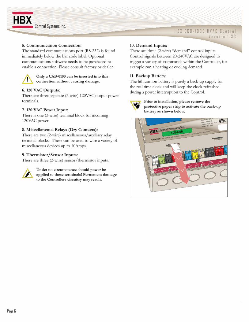
5. Communication Connection:The standard communications port (RS-232) is found immediately below the bar code label. Optional communications software needs to be purchased to enable a connection. Please consult factory or dealer.
Only a CAB-0100 can be inserted into this connection without causing damage.
6. 120 VAC Outputs:There are three separate (3-wire) 120VAC output power terminals.
7. 120 VAC Power Input:�������������[\&����]���� ������������������ ����120VAC power.
8. Miscellaneous Relays (Dry Contacts):There are two (2-wire) miscellaneous/auxiliary relay ��� ����������?������������������������������������ �miscellaneous devices up to 10Amps.
9. Thermistor/Sensor Inputs:There are three (2-wire) sensor/thermistor inputs.
Under no circumstance should power be applied to these terminals! Permanent damage to the Controllers circuitry may result.
10. Demand Inputs:���������������[^&����]�@� �J���������������?��Control signals between 20-240VAC are designed to trigger a variety of commands within the Controller, for example run a heating or cooling demand.
11. Backup Battery:���������� &�������������������������&������������������������ ���������������������������������������during a power interruption to the Control.
Prior to installation, please remove the protective paper strip to activate the back-up battery as shown below.
H B X E C O - 1 0 0 0 H V A C C o n t r o lV e r s i o n 1 . 3 3
© HBX Control Systems Inc. 2012 Page 7
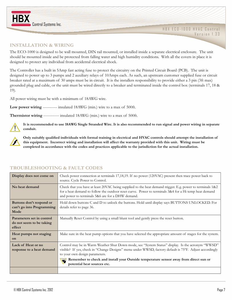
INSTALLATION & WIRINGThe ECO-1000 is designed to be wall mounted, DIN rail mounted, or installed inside a separate electrical enclosure. The unit should be mounted inside and be protected from falling water and high humidity conditions. With all the covers in place it is �������������������������������� ������������������������?
The Controller has a built in 5Amp fast acting fuse to protect the circuitry on the Printed Circuit Board (PCB). The unit is designed to power up to 3 pumps and 2 auxiliary relays of 10Amps each. As such, an upstream customer supplied fuse or circuit �������������� "� � ��� �\*� ��� �����������������?��_����������������������������������������������������\�����[\��� "]��������������������������������� ������������������������������������ �������������������������"�[��� �����'`��'{�|�19).
All power wiring must be with a minimum of 18AWG wire.
Low power wiring ----------- insulated 18AWG (min.) wire to a max of 500ft.
Thermistor wiring ------------ insulated 18AWG (min.) wire to a max of 500ft.
It is recommended to use 18AWG Single Stranded Wire. It is also recommended to run signal and power wiring in separate conduit.
������������ �������������������������������������������������������������������������������������� �this equipment. Incorrect wiring and installation will affect the warranty provided with this unit. Wiring must be completed in accordance with the codes and practices applicable to the jurisdiction for the actual installation.
TROUBLESHOOTING & FAULT CODES
Display does not come on %��������������������������� �����'`�'{�'}?�_� ����������['^*>!%]��������������������������������source. Cycle Power to Control.
No heat demand %������������������������^*>!%��������������������������� ���������?�$?�?������������� �����'|^����������� ����������������������������������?��Z����������� �����\|~������;���� ������� ���������������� ������|�����������;��� �?
Buttons don’t respond or can’t go into Programming Mode
;���������������%��������������������������?�;�������������������<�����������%�$�?�����details refer to page 36.
Parameters set in control do not seem to be taking effect
Manually Reset Control by using a small blunt tool and gently press the reset button.
Heat pumps not staging on
#��������������������� �������������������������������������������� ������� �������������������� ?
Lack of Heat or no response to a heat demand
%������� ���������� ������������������ ��������@����� ������J������?��_����������� �@����J�����������_� ���������������@%������������J� �������������������������������`���?��!���������������to your own design parameters.
Remember to check and install your Outside temperature sensor away from direct sun or potential heat sources etc.

H B X E C O - 1 0 0 0 H V A C C o n t r o lV e r s i o n 1 . 3 3
Page 8
White (1-2) Demand 1: 2-wire control input 20-240VAC
Green (3-4) Demand 2: 2-wire control input 20-240VAC
Black (5-6) Demand 3: 2-wire control input 20-240VAC
Red (7-8) Therm 1: 2-wire thermistor $�?�����������
Brown (9-10) Therm 2: 2-wire thermistor Eg. GND sensor
Blue (11-12) Therm 3: 2-wire thermistor Eg. outdoor sensor
Yellow (13-14) Relay 1: misc. auxiliary 10Amps
Natural (15-16) Relay 2: misc. auxiliary 10Amps.
Black (17-19) Input Power: 3-wire This is the main input power supply connection. 17 is line, 18 is neutral and 19 is earth ground.
Red (20-22) Pump 1: 3-wire 120VAC output power to pump or fan number 1. 20 is line, 21 is neutral and 22 is earth ground.
Blue (23-25) Pump 2: 3-wire 120VAC output power to pump or fan number 2. 23 is line, 24 is neutral and 25 is earth ground.
Orange (26-28) Pump 3: 3-wire 120VAC output power to pump or fan number 3. 26 is line, 27 is neutral and 28 is earth ground. For Geothermal applications this terminal is used for controlling reversing valves.
Terminals 7-12 must not be subjected to any external power source
Input: 120VAC 60Hz 5A
Relays: 240VAC 10A
Demand Signal: 20 - 240V
Model: CPU - 1000
CAUTION, RISK OF ELECTRICAL SHOCK - DISCONNECT POWER PRIOR TO SERVICING
Certified to CSA C22.2 No 24 Conforms to UL Standard 873
Centr a l Proces s i n g U n i t
ECO-1000
White Green Black Red Brown Blue Yellow Natural Black Red Blue Orange
DEMAND DEMAND DEMAND THERM THERM THERM RELAY RELAY PUMPPUMPPUMPINPUT
POWER1
1 3 5 7 9 11 13 152 4 6 8 10 12 14 16 26232017 27242118 28252219
1 12 2 2 1 2 33 3
Control Systems Inc.
ComfortControlInnovation
H B X E C O - 1 0 0 0 H V A C C o n t r o lV e r s i o n 1 . 3 3
Page 9
Summ
ary o
f Par
amet
ers
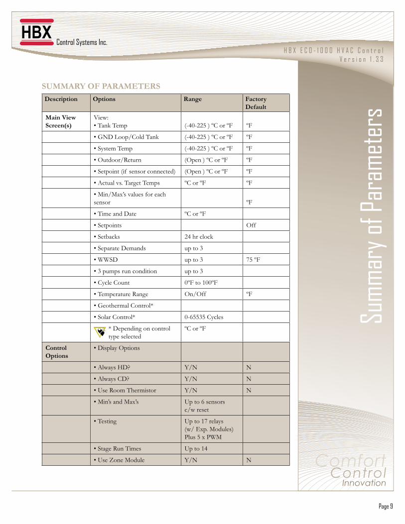
SUMMARY OF PARAMETERS
Description Options Range Factory Default
Main View Screen(s)
>������������ � (-40-225 ) ºC or ºF
ºF
�����������%������ (-40-225 ) ºC or ºF ºF
������� ��� � (-40-225 ) ºC or ºF ºF
���������Q����� (Open ) ºC or ºF ºF
�����������[�� ����������������] (Open ) ºC or ºF ºF
��!�������?��������� �� ºC or ºF ºF
��#���#"�����������������sensor
ºF
���� ������� ºC or ºF
����������� Off
��������� ^~���������
����������� �� up to 3
������ up to 3 75 ºF
��\��� ��������������� up to 3
��%�����%���� 0ºF to 100ºF
���� ��������Q��� On/Off ºF
��������� ��%�������
�������%������� 0-65535 Cycles
����������������������type selected
ºC or ºF
Control Options
����������������
��!�����;�� Y/N N
��!�����%�� Y/N N
������Q�� ����� ����� Y/N N
��#�������#"�� Up to 6 sensorsc/w reset
��������� Up to 17 relays(w/ Exp. Modules)Plus 5 x PWM
�������Q����� �� Up to 14
�����������#���� Y/N N

H B X E C O - 1 0 0 0 H V A C C o n t r o lV e r s i o n 1 . 3 3
Page 10
Description Options Range Factory Default
Heat Pump Options & Geothermal Controls
����������������
��^������;Z Y/N N
����"������� Y/N N
����"����� Y/N N
�������&;��;� Y/N N
��;����� ������������� Auto/40/30/20/10 Auto
��#���;���Z� ����&�� � 1-20 Mins 1 Mins
��#"�;���Z� �����&�� � 1 - 254 Sec 60 Sec
������ �������['~���#�����] 1 to 2 Single Stage
��Z� ��������� Y/N
��'�Z� ��;���Z� � Y/N N (off)
��Z� ����������� Y/N N (off)
��Q�����;���Z� �� Y/N Y
��Z� ���!�������� Y/N N
��Z����Z���� 1 - 240 Sec 1 Sec
��Q������� ����� � Y/N Y
�����������Z������ Y/N N
Change Design(Applicable Only to Geothermal Applications)
�������������� ��� � 0ºF to 225ºF 135ºF
���������Q�� ��� � -50ºF to 100ºF 70ºF
������������������ � -50ºF to 100ºF -10ºF
��#�������� ��� � 0ºF to 150ºF 75ºF
������ 0ºF to 100ºF 75ºF
Solar Controls ��������������
������ �%����������� 1-4 '����
��������� � 1-225°F 70°F
��������� � 1-225°F 10°F
��#���[<����]��� � 1-225°F 70°F
��<�������� ��� � 1-225°F 70°F
��#"�[�� �]��� � 1-225°F 190°F

H B X E C O - 1 0 0 0 H V A C C o n t r o lV e r s i o n 1 . 3 3
© HBX Control Systems Inc. 2012 Page 11
Description Options Range Factory Default
���������������
��#������� 1-225°F 100°F
��#"����� 1-225°F 200°F
�������Z� ��^������ � 50-220°F 50°F
��#��������Z� ������� � 1-20 Mins 2 Mins
������������� Auto-225°F 4°F
Setpoint Options
�����������' o Setpoint Temp o Heating ����%����_�������� o Differential o Lag Time o Setpoint Demand
Off/1ºF to 225ºF Heat/Cool Y/N 2ºF to 100ºF 0S to 600S No/Hot/Cold
�����������^���\ As Above
Setback Options
������������� Y/N N
������������� o Start Time 1 o End Time 1 o Start Time 2 o End Time 2 o Start Time 3 o End Time 3
*�**���^~�***�**���^~�***�**���^~�***�**���^~�***�**���^~�***�**���^~�**
��������������� Target vs. Actual
������;���Z� ������ Target vs. Actual
H B X E C O - 1 0 0 0 H V A C C o n t r o lV e r s i o n 1 . 3 3
Page 12
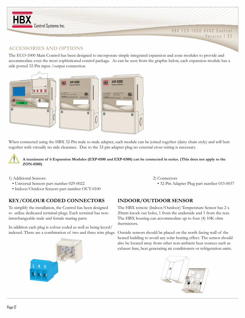
ACCESSORIES AND OPTIONSThe ECO-1000 Main Control has been designed to incorporate simple integrated expansion and zone modules to provide and ��� ������������� �����������������������������?��!���������������� ������������������������"������� ���������side ported 32-Pin input /output connection.
When connected using the HBX 32-Pin male to male adapter, each module can be joined together (daisy chain style) and will butt together with virtually no side clearance. Due to the 32-pin adapter plug no external cross wiring is necessary.
A maximum of 6 Expansion Modules (EXP-0100 and EXP-0300) can be connected in series. (This does not apply to the ZON-0500)
']�!���������������� � � � � � � � ^]�%��������� � ������������������������� ����*^}&**^^� � � � � ������\^&Z���!�����Z���������� ����*\\&**\` � ��_�������������������������� �������&*'**
KEY/COLOUR CODED CONNECTORSTo simplify the installation, the Control has been designed to utilize dedicated terminal plugs. Each terminal has non-interchangeable male and female mating parts.
_���������������������������������������������������indexed. There are a combination of two and three wire plugs.
INDOOR/OUTDOOR SENSORThe HBX remote (Indoor/Outdoor) Temperature Sensor has 2 x ^* ������������������'���� ���������������'���� ��������?��The HBX housing can accommodate up to four (4) 10K ohm thermistors.
Outside sensors should be placed on the north facing wall of the heated building to avoid any solar heating effect. The sensor should also be located away from other non-ambient heat sources such as exhaust fans, heat generating air conditioners or refrigeration units.
H B X E C O - 1 0 0 0 H V A C C o n t r o lV e r s i o n 1 . 3 3
© HBX Control Systems Inc. 2012 Page 13
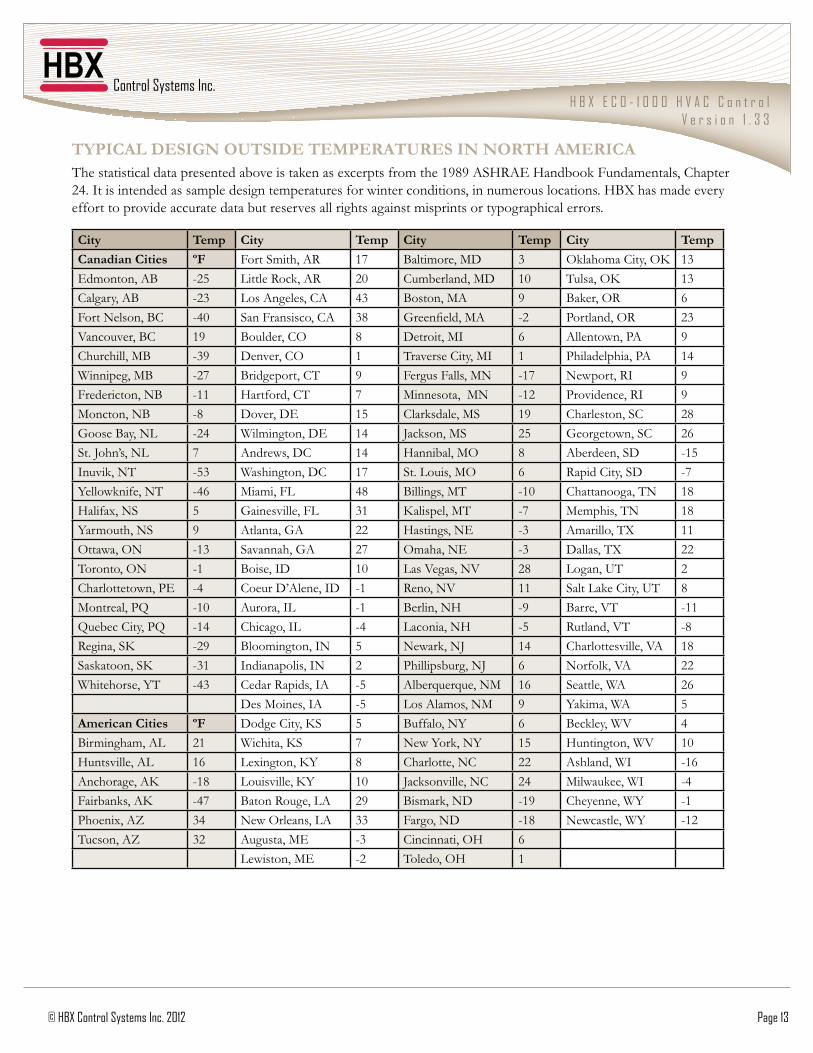
TYPICAL DESIGN OUTSIDE TEMPERATURES IN NORTH AMERICA�����������������������������������������"���������� �����'}{}�!�;Q!$�;��������� �������%������24. It is intended as sample design temperatures for winter conditions, in numerous locations. HBX has made every effort to provide accurate data but reserves all rights against misprints or typographical errors.
City Temp City Temp City Temp City Temp
Canadian Cities ºF Fort Smith, AR 17 Baltimore, MD 3 ����� �%������� 13Edmonton, AB -25 �������Q�����!Q 20 Cumberland, MD 10 Tulsa, OK 13Calgary, AB -23 Los Angeles, CA 43 Boston, MA 9 <������Q 6Fort Nelson, BC -40 San Fransisco, CA 38 ����������#! -2 Portland, OR 23Vancouver, BC 19 Boulder, CO 8 Detroit, MI 6 Allentown, PA 9Churchill, MB -39 Denver, CO 1 Traverse City, MI 1 Philadelphia, PA 14Winnipeg, MB -27 Bridgeport, CT 9 Fergus Falls, MN -17 Newport, RI 9Fredericton, NB -11 Hartford, CT 7 Minnesota, MN -12 Providence, RI 9Moncton, NB -8 Dover, DE 15 %��������#� 19 Charleston, SC 28Goose Bay, NL -24 Wilmington, DE 14 ��������#� 25 Georgetown, SC 26St. John’s, NL 7 Andrews, DC 14 Hannibal, MO 8 Aberdeen, SD -15_��������� -53 Washington, DC 17 St. Louis, MO 6 Rapid City, SD -7��������������� -46 Miami, FL 48 Billings, MT -10 Chattanooga, TN 18Halifax, NS 5 Gainesville, FL 31 Kalispel, MT -7 Memphis, TN 18Yarmouth, NS 9 Atlanta, GA 22 Hastings, NE -3 Amarillo, TX 11Ottawa, ON -13 Savannah, GA 27 Omaha, NE -3 Dallas, TX 22Toronto, ON -1 Boise, ID 10 Las Vegas, NV 28 Logan, UT 2Charlottetown, PE -4 Coeur D’Alene, ID -1 Reno, NV 11 ��������%������� 8Montreal, PQ -10 Aurora, IL -1 Berlin, NH -9 Barre, VT -11Quebec City, PQ -14 Chicago, IL -4 Laconia, NH -5 Rutland, VT -8Regina, SK -29 Bloomington, IN 5 ��������� 14 Charlottesville, VA 18����������� -31 Indianapolis, IN 2 Phillipsburg, NJ 6 ���������>! 22Whitehorse, YT -43 Cedar Rapids, IA -5 Alberquerque, NM 16 Seattle, WA 26
Des Moines, IA -5 Los Alamos, NM 9 ��� ���! 5American Cities ºF Dodge City, KS 5 Buffalo, NY 6 <���������> 4Birmingham, AL 21 Wichita, KS 7 ������������ 15 Huntington, WV 10Huntsville, AL 16 Lexington, KY 8 Charlotte, NC 22 Ashland, WI -16Anchorage, AK -18 Louisville, KY 10 ��������������% 24 #����������_ -4���������!� -47 Baton Rouge, LA 29 <�� ������ -19 Cheyenne, WY -1Z�����"��!� 34 New Orleans, LA 33 Fargo, ND -18 Newcastle, WY -12��������!� 32 Augusta, ME -3 Cincinnati, OH 6
Lewiston, ME -2 Toledo, OH 1

H B X E C O - 1 0 0 0 H V A C C o n t r o lV e r s i o n 1 . 3 3
Page 14
TEMPERATURE CONVERSION / RESISTANCE TABLE FOR HBX 029-0022, 029-0032 & OUT-0100 10K TEMPERATURE SENSORS
Celsius Fahrenheit Ohms Celsius Fahrenheit Ohms Celsius Fahrenheit Ohms
-30-29-28-27-26-25-24-23-22-21-20-19-18-17-16-15-14-13-12-11-10-9-8-7-6-5-4-3-2-101234567891011121314
-22-20.2-18.4-16.6-14.8-13-11.2-9.4-7.6-5.8-4-2.2-0.41.43.256.88.610.412.21415.817.619.421.22324.826.628.430.23233.835.637.439.24142.844.646.448.25051.853.655.457.2
177,000166,342156,404147,134138,482130,402122,807115,710109,075102,86897,06091,58886,46381,66277,16272,94068,95765,21961,71158,41555,31952,39249,64047,05244,61742,32440,15338,10936,18234,36732,65431,03029,49828,05226,68625,39624,17123,01321,91320,88319,90318,97218,09017,25516,464
151617181920212223242526272829303132333435363738394041424344454647484950515253545556575859
5960.862.664.466.26869.871.673.475.27778.880.682.484.28687.889.691.493.29596.898.6100.4102.2104105.8107.6109.4111.2113114.8116.6118.4120.2122123.8125.6127.4129.2131132.8134.6136.4138.2
15,71415,00014,32313,68113,07112,49311,94211,41810,92110,44910,0009,5719,1648,7768,4078,0567,7207,4017,0966,8066,5306,2666,0145,7745,5465,3275,1174,9184,7274,5444,3704,2034,0423,8893,7433,6033,4693,3403,2173,0992,9862,7872,7742,6752,579
60616263646566676869707172737475767778798081828384858687888990919293949596979899100101102103104
140141.8143.6145.4147.2149150.8152.6154.4156.2158159.8161.6163.4165.2167168.8170.6172.4174.2176177.8179.6181.4183.2185186.8188.6190.4192.2194195.8197.6199.4201.2203204.8206.6208.4210.2212213.8215.6217.4219.2
2,4882,4002,3152,2352,1572,0832,0111,9431,8761,8131,7521,6931,6371,5821,5301,4801,4311,3851,3401,2971,2551,2151,1771,1401,1041,0701,0371,005974944915889861836811787764742721700680661643626609

H B X E C O - 1 0 0 0 H V A C C o n t r o lV e r s i o n 1 . 3 3
© HBX Control Systems Inc. 2012 Page 15
Limited Warranty;<=�%��������������������� ��������������������������� ��������������� �������� ��������������� ����������������for a period of 24 months from date of manufacture or 12 months from date of purchase from an HBX Authorized Dealer, if within the above documented period after date of manufacture.
If the product proves to be defective within the applicable warranty period, HBX on its sole discretion will repair or replace said ������?��Q����� ����������� ������������������������� �����������������������������������������������������������������?��Replacement product need not be of identical design or model. Any repair or replacement product pursuant to this warranty shall be warranted for not less than 90 days from date of such repair, irrespective of any earlier expiration of original warranty period. When HBX provides replacement, the defective product becomes the property of HBX Controls.
�������������������������������������������������� �������������������������������������;<=�%�����������������������������!���������!�������������������Q������#������!�������������� ����[Q#!��]?��Z���� ��� ������������������� ��dated invoice/receipt must be provided to expedite the issuance of a Factory RMA.
!�������Q#!��� ��������������������������������������� �������������������������������������������������������������������������������������������������� ������������?������Q#!��� ���� ������������������������������� �����������������������������������������?������������ ������� �������������������������������;<=����������������� � ������shipping/insurance prepaid by the warranty claimant.
!����������������������;<=����������������������������Q#!��� ���������������������������������������������at purchaser’s expense. HBX reserves the right, if deemed necessary, to charge a reasonable levy for costs incurred, additional to mailing or shipping costs.
Limitation of Warranties.If the HBX product does not operate as warranted above the purchasers sole remedy shall be, at HBX’s option, repair or replacement. The foregoing warranties and remedies are exclusive and in lieu of all other warranties, expressed or implied, either ������������������������ ������������������������������������������������ � ��������������������������������������������application. HBX neither assumes nor authorizes any other person to assume for it any other liability in connection with the sale, installation maintenance or use of HBX Controls products.
HBX shall not be liable under this warranty; if its testing and examination discloses that the alleged defect in the product does not exist or was caused by the purchasers or third persons misuse, neglect, improper installation or testing, unauthorized attempts to ���������������������������������������� ������������������������������������������������������?
Limitation of Liability._����������������;<=����������������� ��������������������� ����������� ����������������� ��������������������������consequential or indirect damages arising out of the installation, maintenance, commissioning, performance, failure or interruption of an HBX product, however caused and on any theory of liability. This limitation will apply even if HBX has been advised of the possibility of such damage.
Local Law.������� ��������������� ������������������������������������������?��������������� ���������������������������������from state to state in the United States, from Province to Province in Canada and from Country to Country elsewhere in the world.
��������"������������ ��������������� ������������������������������������������� �������������� �� �����������consistent with such local law. Under such local law, certain disclaimers and limitations of this statement may not apply to the purchaser. For example, some states in the United States, as well as some governments outside the United States (including %����Z��������]�� ���Z���������������� �������� �������������������� ������� ��� ���������������������������� ��consumer (e.g. United Kingdom); Otherwise restrict the ability of a manufacturer to enforce such disclaimers or limitations; or Grant the purchaser additional warranty rights which the manufacturer cannot disclaim, or not allow limitations on the duration of implied warranties.

Page 16© HBX Control Systems Inc. 2012
Phone: +1 (403) 720-0029 Fax: +1 (403) 720-0054 Email: inf o @ hbxcontrols.com Web: www.hbxcontrols.com
HBX Control Systems Inc.4516 - 112th Avenue SECalgary, AB Canada T2C 2K2
v3.6
Related Documents


![EGR1 Plays Synthesis of HBx(+) Hepatocytesdownloads.hindawi.com/journals/mi/2015/372750.pdf · HBx) [ ], HepG cells (a human hepatocarcinomal cell line, HB- , ATCC, VA), and HepG-HBx](https://static.cupdf.com/doc/110x72/5f57c5b0381d5a575c0d116d/egr1-plays-synthesis-of-hbx-hbx-hepg-cells-a-human-hepatocarcinomal-cell.jpg)
