Journal of Engineering Science and Technology Vol. 10, No. 9 (2015) 1131 - 1143 © School of Engineering, Taylor’s University 1131 GENERAL FAULT ADMITTANCE METHOD LINE- TO- LINE-TO-LINE UNSYMMETRICAL FAULT J. D. SAKALA*, J. S. J. DAKA Faculty of Engineering and Technology, University of Botswana, Private Bag UB0061, Gaborone, Botswana *Corresponding Author: [email protected] Abstract Line-to-line-to-line unsymmetrical faults either involving or not involving ground are in the classical fault analysis approach difficult to analyse. This is because the classical solution requires use of the knowledge of connection of symmetrical component sequence networks for various common faults. In this approach, the phase fault constraints are converted into symmetrical sequence constraints and the sequence networks connected in a way that satisfies the constraints. The symmetrical component constraints for an unsymmetrical three-phase fault not involving ground do not lend themselves easy to the connection of the sequence networks. The exception is that, because the phase currents at the fault summate to zero, the zero sequence current is zero and therefore the zero sequence network is not connected. The connection of the positive and negative sequence networks is difficult to deduce when the fault is unsymmetrical. A classical solution is therefore difficult to find. In contrast, a solution by the general method of fault admittance matrix does not require prior knowledge of how the sequence networks are connected. It is therefore more versatile than the classical methods. The paper presents a procedure for solving a three-phase unsymmetrical fault, with different fault impedances, hence fault admittances in each phase. A computer program based on the general fault admittance method is developed and used to analyse an unsymmetrical three-phase fault on a simple power system with a delta-earthed-star connected transformer. Keywords: Unbalanced faults analysis, Line-to-line-to-line unsymmetrical fault, Fault admittance matrix, Delta-earthed-star transformer. 1. Introduction The paper presents a method for solving an unsymmetrical line-to-line-to-line fault using the general fault impedance method. The general fault admittance method differs from the classical approaches based on symmetrical components

Welcome message from author
This document is posted to help you gain knowledge. Please leave a comment to let me know what you think about it! Share it to your friends and learn new things together.
Transcript
Journal of Engineering Science and Technology Vol. 10, No. 9 (2015) 1131 - 1143 © School of Engineering, Taylor’s University
1131
GENERAL FAULT ADMITTANCE METHOD LINE- TO- LINE-TO-LINE UNSYMMETRICAL FAULT
J. D. SAKALA*, J. S. J. DAKA
Faculty of Engineering and Technology, University of Botswana, Private Bag UB0061, Gaborone, Botswana
*Corresponding Author: [email protected]
Abstract
Line-to-line-to-line unsymmetrical faults either involving or not involving ground are in the classical fault analysis approach difficult to analyse. This is because the classical solution requires use of the knowledge of connection of symmetrical component sequence networks for various common faults. In this approach, the phase fault constraints are converted into symmetrical sequence constraints and the sequence networks connected in a way that satisfies the constraints. The symmetrical component constraints for an unsymmetrical three-phase fault not involving ground do not lend themselves easy to the connection of the sequence networks. The exception is that, because the phase currents at the fault summate to zero, the zero sequence current is zero and therefore the zero sequence network is not connected. The connection of the positive and negative sequence networks is difficult to deduce when the fault is unsymmetrical. A classical solution is therefore difficult to find. In contrast, a solution by the general method of fault admittance matrix does not require prior knowledge of how the sequence networks are connected. It is therefore more versatile than the classical methods. The paper presents a procedure for solving a three-phase unsymmetrical fault, with different fault impedances, hence fault admittances in each phase. A computer program based on the general fault admittance method is developed and used to analyse an unsymmetrical three-phase fault on a simple power system with a delta-earthed-star connected transformer.
Keywords: Unbalanced faults analysis, Line-to-line-to-line unsymmetrical fault, Fault admittance matrix, Delta-earthed-star transformer.
1. Introduction
The paper presents a method for solving an unsymmetrical line-to-line-to-line fault using the general fault impedance method. The general fault admittance method differs from the classical approaches based on symmetrical components

1132 J. D. Sakala and J. S. J. Daka
Journal of Engineering Science and Technology September 2015, Vol. 10(9)
Nomenclatures Ifpj Phase current in the faulted bus bar j Ifsj Symmetrical component current at the faulted bus bar j Vfs1 Symmetrical component voltage at the faulted bus bar 1 Yaf Phase a fault admittance Ybf Phase b fault admittance Ycf Phase c fault admittance Yfs Symmetrical fault admittance Ygf Ground fault admittance
Greek Symbols
α Complex operator 1∠120°
since it does not require prior knowledge of how the sequence components of currents and voltages are related [1-7]. In the classical approach, knowledge of how the sequence components are related is required because the sequence networks must be connected in a prescribed way for a particular fault. Then the sequence currents and voltages at the fault are determined, after which symmetrical component currents and voltages in the rest of the network are calculated. Phase currents and voltages are found by transforming the respective symmetrical component values [8-11].
The fault admittance method is general in the sense that any fault impedances can be represented, provided the special case of a zero impedance fault is catered for. This paper discusses a procedure for simulating and solving an unsymmetrical line-to-line-to-line fault.
2. Background
A line-to-line-to-line fault presents low value impedances, with zero values for direct short circuits or metallic faults, between the three phases at the point of a fault in the network. In general, a fault may be represented as shown in Fig. 1.
In Fig. 1, a fault at a bus bar is represented by fault admittances in each phase, i.e., the inverse of the fault impedance in the phase, and the admittance in the ground path. Note that the fault admittance for a short-circuited phase is represented by an infinite value, while that for an open-circuited phase is a zero value. In a line-to-line-to-line fault the fault is between all the three phases; a, b and c. Thus for a line-to-line-to-line fault the admittance Ygf is zero while the admittances Yaf, Ybf and Ycf are the inverses of the fault impedances in the respective phases.
A systematic approach for using a fault admittance matrix in the general fault admittance method is given by Sakala and Daka [1-7]. The method is based on the work by Elgerd [8] details of which are summarized in Appendix A.
3. Line-to-Line-to-Line Unsymmetrical Fault Simulation
The symmetrical component fault admittance matrix for a general fault admittance matrix when the ground is not involved, i.e., Ygf is zero, reduces to (Appendix A):

General Fault Admittance Method Line-to-Line-to-Line Unsymmetrical Fault 1133
Journal of Engineering Science and Technology September 2015, Vol. 10(9)
( )( )
++++−
++−++
++=
000
0
01 2
2
cfbfcfafbfafcfafbfafcfbf
cfafbfafcfbfcfbfcfafbfaf
cfbffa
fs YYYYYYYYYYYY
YYYYYYYYYYYY
YYYY αα
αα (1)
The values Yaf, Ybf and Ycf are the fault admittances in the faulted phases. The impedances required to simulate the line-to-line-to-line unsymmetrical fault in general terms are the impedances in the faulted phases. In the current work, the fault impedances are as follows: in the a phase zero, in the b phase j0.1 and j0.2 in the c phase. Furthermore, since Yaf is infinite the symmetrical component fault admittance matrix becomes:
( )( )
++−
+−+
=
000
0
02
2
cfbfcfbf
cfbfcfbf
fs YYYY
YYYY
Y αααα
(2)
The symmetrical component fault admittance matrix may be substituted in Eq. (A-4) in Appendix A to obtain a simplified value of Ifsj as:
( )( )
−−
++
×++++
=−
−+−+ 0
3
312
0
cfbf
cfbfsjjcfbf
cfbfsjjsjjsjjsjjcfbf
j
fsj YY
YYZYY
YYZZZZYY
VI αα (3)
The simplified expression is useful for validating the results from the computer program.
Fig. 1. General fault representation.
4. Computation of the Line-to-Line-to-Line Unsymmetrical Fault
Equations (1) to (3) form the basis of a computer simulation program to solve unbalanced faults for a general power system using the fault admittance matrix method. The program is applied on a power system comprising of three bus bars to solve for a line-to-line-to-line unsymmetrical fault.
Figure 2 shows a simple three bus bar power system with one generator, one transformer and one transmission line. The system is configured based on the simple power system that Saadat uses [9].

1134 J. D. Sakala and J. S. J. Daka
Journal of Engineering Science and Technology September 2015, Vol. 10(9)
Fig. 2. Sample three bus bar system [9].
The power system per unit data is given in Table 1, where the subscripts 1, 2, and 0 refer to the positive, negative and zero sequence values respectively. The neutral point of the generator is grounded through zero impedance.
Table 1. Power system data.
Item Sbase
(MVA) Vbase (kV)
X1
(pu) X2
(pu) X0
(pu) G1 100 20 0.15 0.15 0.05 T1 100 20/220 0.10 0.10 0.10 L1 100 220 0.25 0.25 0.71
The transformer windings are delta connected on the low voltage side and earthed-star connected on the high voltage side, with the neutral solidly grounded. The phase shift of the transformer is 30˚, i.e., from the generator side to the line side. Figure 3 shows the transformer voltages for a Yd11 connection which has a 30˚ phase shift.
Fig. 3. Delta-star transformer voltages for Yd11.
The computer program incorporates an input program that calculates the sequence admittance and impedance matrices and then assembles the symmetrical component bus impedance matrix for the power system. The symmetrical component bus impedance incorporates all the sequences values and has 3n rows and 3n columns where n is the number of bus bars. In general, the mutual terms between sequence values are zero as a three-phase power system is, by design, balanced.
The power system is assumed to be at no load before the occurrence of a fault. In practice, the pre-fault conditions, established by a load flow study may be used.

General Fault Admittance Method Line-to-Line-to-Line Unsymmetrical Fault 1135
Journal of Engineering Science and Technology September 2015, Vol. 10(9)
For developing a computer program the assumption of no load, and therefore voltages of 1.0 per unit at the bus bars and in the generator, is adequate.
The line-to-line-to-line unsymmetrical fault is at bus bar 1, the load bus bar. The line-to-line-to-line unsymmetrical fault is described by the impedances in the respective phases, i.e., 0 Ω, j0.1 Ω and j0.2 Ω in the a, b and c phases respectively.
The presence of the delta earthed-star transformer poses a challenge in terms of its modelling. In the computer program, the transformer is modelled in one of two ways; as a normal star-star connection, for the positive and negative sequence networks or as a delta-star transformer with a phase shift. In the former model, the phase shifts are incorporated when assembling the sequence currents to obtain the phase values.
In particular, on the delta-connected side of the transformer the positive sequence currents’ angles are increased by the phase shift while the angle of the negative sequence currents are reduced by the same value. The zero sequence currents, if any, are not affected by the phase shifts.
Both models for the delta star transformer give same results. The √3 line current factor is used to find the line currents on the delta side of the delta star transformer.
5. Results and Discussions
A summary of results obtained from a computer simulation of the power system as given in Section 4 are presented in this section. Further results details are provided Appendix B.
5.1. Symmetrical component impedances at the faulted bus bar
The Thevenin’s self-sequence impedances of the network seen from the faulted bus bar are:
0.8125 j 00
0 0.5 j 0
000.5 j (4)
The connection of the sequence networks for the line-to-line-to-line unsymmetrical fault is not required to perform the study by the general fault admittance method. The phase and symmetrical component fault matrices are found in the course of the study and the latter is part of the output results shown in Appendix B, Table B.1.
5.2. Symmetrical fault admittance matrix
The symmetrical component fault admittance matrix obtained from the program for the line-to-line-to-line unsymmetrical fault shown in Eq. (5) is in agreement with the theoretical value, obtained using Eq. (2).
−−
−
0 00
0 15 j- 5.7j3301.4
05.7j3301.415 j- (5)

1136 J. D. Sakala and J. S. J. Daka
Journal of Engineering Science and Technology September 2015, Vol. 10(9)
5.3. Sequence fault currents
The symmetrical component fault currents (Positive, negative and zero sequences) at the fault points are equal to the values obtained using Eq. (3):
°−∠
°−∠
=
0
601619.0
906822.1
fsjI (6)
Note that the zero sequence current in Eq. (6) is zero, which is consistent with theory.
5.4. Phase fault currents
The phase currents in the fault are given by:
°∠
°∠
°−∠
=
0.335244.1
5.1446900.1
5.878242.1
fpjI (7)
Note that the currents in Eq. (7) summate to zero as there is no current flowing into the ground from the fault.
The phase fault currents are highest in the phase a, the phase with the least fault impedance. The next largest current is phase b, which had the second lowest fault impedance. Phase c, with the largest fault impedance has the least fault current.
Figure 4 shows the transformer and transmission line phase currents. The phase currents in the transmission line are equal to the currents in the fault. Note that the current at the receiving end of the line is by convention considered as flowing into the line, rather than out of it.
The currents on the line side are equal to the currents in the line, after allowing for the sign change due to convention. The currents in the transformer windings satisfy the ampere-turn balance requirements of the transformer. The magnitudes of the currents at the sending end of the transformer, the delta connected side, are √3 times the magnitudes of the currents in the phase windings, although not a phase-to-phase correspondence. While the magnitude in phase a on the delta connected side is √3 times the current magnitude on the star connected side, the magnitude in the b phase on the delta connected side is √3 times the value of the current magnitude in the c phase.
Similarly the magnitude of the current in the c phase on the delta connected side is √3 times the current magnitude in the b phase. The phase fault currents flowing from the generator are equal to the phase currents into the transformer.
5.5. Fault voltages
The symmetrical component voltages at the fault point are given in Eq. (8). They show that the zero sequence voltage is zero, which is consistent with theory. The positive and negative sequence voltages are not equal.
°∠
°∠
=
0
2100809.0
01589.0
1fsV (8)

General Fault Admittance Method Line-to-Line-to-Line Unsymmetrical Fault 1137
Journal of Engineering Science and Technology September 2015, Vol. 10(9)
The phase voltages at the bus bars are given in Table 2. The voltages at bus bar 1 are the voltages at the fault point. The phase voltages at the fault are lowest in phase a, which has the lowest fault impedance, followed by that in phase b, with the next lowest fault impedance.
Fig. 4. Transformer currents for a line-to-line-to-line unsymmetrical fault.
Table 2. Phase voltages at the bus bars.
Bus Bar
Number
Phase a Phase b Phase c
Magnitude/Angle
[°] Magnitude/Angle [°] Magnitude/Angle [°]
1 0.0976/-24.5° 0.1783 / 267.0° 0.2325 / 110.0°
2 0.5448/-2.1° 0.5809 / 244.0° 0.6148 / 118.1°
3 0.7267/ 31.0° 0.7688 / 89.1° 0.7481 / 148.1°
The phase voltages at bus bar 2 are nearly equal being 54.5%, 58.1% and 61.5% of the pre-fault values in the a, b and c phases respectively.
The phase voltages at bus bar 3are nearly balanced with magnitudes of 72.7%, 76.8% and 74.6% of the pre-fault values in the a, b and c phases respectively. The phase voltages at bus bar 3 lead the phase voltages at bus bar 2 by 33.1˚, 26.9˚ and 30.0˚ in the a, b and c phases respectively.
5.6. Future work
The work presented in this paper has shown that a line-to-line-to-line unsymmetrical fault can be solved using the general fault admittance method provided a small enough impedance is used to simulate a zero impedance fault. In future work the unsymmetrical fault will be rotated around the phases to demonstrate the versatility of the method. That is the fault impedances of 0 Ω,
j0.1 Ω and j0.2 Ω will be in phases b, c and a respectively for one study and in

1138 J. D. Sakala and J. S. J. Daka
Journal of Engineering Science and Technology September 2015, Vol. 10(9)
phases c, a and b respectively for another study. The method will also be applied to solve various faults on a practical system.
6. Conclusions
A line-to-line-to-line unsymmetrical fault has been solved using the general fault admittance method. This type of fault is difficult to solve using the classical symmetrical components approach based on the connection of the sequence component networks at the fault point. The difficulty arises because the phase and symmetrical component constraints do not lead to suggest a simple connection of the sequence component networks.
The results show that the phase voltages on the delta side of a delta earthed star connected transformer, with the fault on the star side, are nearly balanced. This effect is consistent with the effect that a delta star connected transformer has on unbalanced loads on the star side.
The line-to-line-to-line unsymmetrical fault is interesting for studying the delta earthed star transformer arrangement. The currents and voltages are nearly balanced on both sides of the transformer. Phase shifts of nearly 30˚ between the voltages on the delta side to those on the star connected side are shown, which is consistent with theory. The results give an insight in the effect that a delta earthed star transformer has on a power system during line-to-line-to-line unsymmetrical faults.
The main advantage of the general fault admittance method is that the user is not required to know beforehand how the sequence networks should be connected at the fault point in order to obtain the sequence currents and voltages. The user can deduce the various relationships from the results. The method is therefore easier to use and teach than the classical approach in which each network is solved in isolation and then the results combined to obtain the phase quantities.
References
1. Sakala, J.D.; and Daka, J.S.J. (2014). General fault admittance method solution of a balanced line-to-line-to-line fault. Australian Journal of Basic
and Applied Sciences, 8(1), 238-247.
2. Sakala, J.D.; and Daka, J.S.J. (2014). General fault admittance method line-to-line faults in reference and odd phases. International Journal of Electrical
Electronics and Telecommunications Engineering, 45(1), 1374-1383.
3. Sakala, J.D.; and Daka, J.S.J. (2014). General fault admittance method line-to-line-to-ground fault in reference and odd phases. International Journal of
Engineering Research and Applications, 4(2), 679-690.
4. Sakala, J.D.; and Daka, J.S.J. (2013). General fault admittance method solution of a line-to-line fault. International Journal of Advanced Computer
Research, 3(4/13), 130-138.
5. Sakala, J.D.; and Daka, J.S.J. (2013). General fault admittance method solution of a line-to-line-to-ground fault. Australian Journal of Basic and
Applies Sciences, 7(10), 75-85.
General Fault Admittance Method Line-to-Line-to-Line Unsymmetrical Fault 1139
Journal of Engineering Science and Technology September 2015, Vol. 10(9)
6. Sakala, J.D.; and Daka, J.S.J. (2012). General fault admittance method line-to-ground fault in reference and odd phases. International Journal of Applied
Science and Technology, 2(7), 90-104.
7. Sakala J.D.; Daka J.S.J. (2007). Unbalanced fault analysis by the general fault admittance method. Proceedings of the 10
th Botswana Institution of
Engineers International Biennial Conference. Gaborone, Botswana.
8. Elgerd, O.I. (1971). Electric energy systems theory, an introduction. New York: McGraw Hill Inc.
9. Saadat, H. (2004). Power system analysis (2nd ed.). New York: McGraw Hill.
10. Das, J.C. (2001). Power system analysis, short circuit load flow and
harmonics. New York: Marcel Dekker Inc.
11. El-Hawary, M.E, (1995). Electrical power systems: Design and analysis. New York: IEEE Press Power Systems Engineering Series.
Appendix A
General Fault Admittance Matrix Method for Line-
to-line-to-Line Unsymmetrical Fault
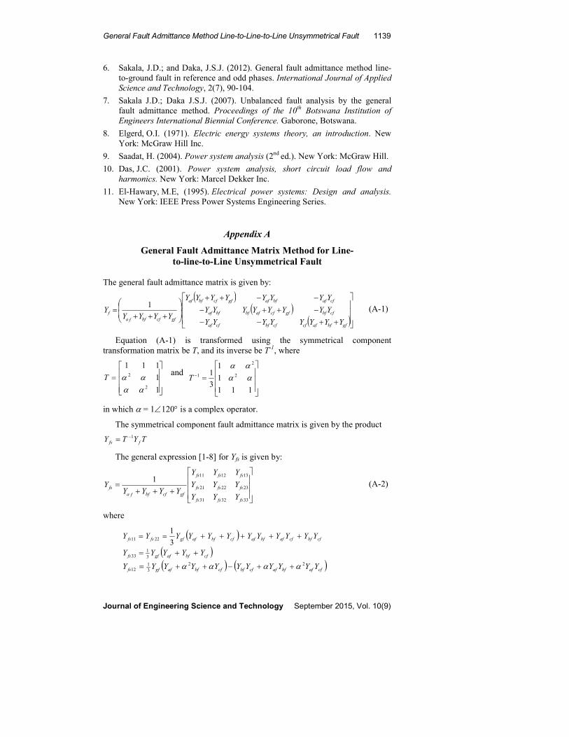
The general fault admittance matrix is given by:
( )( )
( )
++−−
−++−
−−++
+++=
gfbfafcfcfbfcfaf
cfbfgfcfafbfbfaf
cfafbfafgfcfbfaf
gfcfbffa
f
YYYYYYYY
YYYYYYYY
YYYYYYYY
YYYYY
1 (A-1)
Equation (A-1) is transformed using the symmetrical component transformation matrix be T, and its inverse be T-1, where
=
1
1
111
2
2
αα
ααT and
=−
111
1
1
3
1 2
2
1 αααα
T
in which α = 1∠120° is a complex operator.
The symmetrical component fault admittance matrix is given by the product
TYTY ffs
1−=
The general expression [1-8] for Yfs is given by:
+++=
333231
232221
1312111
fsfsfs
fsfsfs
fsfsfs
gfcfbffa
fs
YYY
YYY
YYY
YYYYY
(A-2)
where
( ) cfbfcfafbfafcfbfafgffsfs YYYYYYYYYYYY +++++==3
12211
( )cfbfafgffs YYYYY ++=
31
33
( ) ( )cfafbfafcfbfcfbfafgffs YYYYYYYYYYY 2231
12 αααα ++−++=

1140 J. D. Sakala and J. S. J. Daka
Journal of Engineering Science and Technology September 2015, Vol. 10(9)
( ) ( )cfafbfafcfbfcfbfafgffs YYYYYYYYYYY αααα ++−++= 2231
21
( ) 231
3213 cfbfafgffsfs YYYYYY αα ++== and
( )cfbfafgffsfs YYYYYY αα ++== 231
2331
The above expressions simplify considerably depending on the type of fault.
A.1. Currents in the fault
At the faulted bus bar, say bus bar j, the symmetrical component currents in the fault are given by:
( ) 01sjfssjjfsfsj VYZUYI
−+= (A-3)
where U is the unit matrix:
=
100
010
001
U
and Zsjj is the jjth component of the symmetrical component bus impedance matrix
= −
+
000
00
00
sjj
sjj
sjj
sjj
Z
Z
Z
Z
The element Zsjj+ is the Thevenin’s positive sequence impedance at the faulted bus bar, Zsjj- is the Thevenin’s negative sequence impedance at the faulted bus bar, and Zsjj0 is the Thevenin’s zero sequence impedance at the faulted bus bar. Note that as the network is balanced the mutual terms are all zero.
In Eq. (4) Vsj0 is the pre-fault symmetrical component voltage at bus bar j the
faulted bus bar:
=
=+
−
+
0
0
0
0
V
V
V
V
V
sj
sj
sj
sj
where V+ is the positive sequence voltage before the fault. The negative and zero sequence voltages are zero because the system is balanced prior to the fault.
The phase currents in the fault are then obtained by transformation:
fsj
cfj
bfj
afj
fpj TI
I
I
I
I =
= (A-4)
A.2. Voltages at the bus bars
The symmetrical component voltage at the faulted bus bar j is given by:

General Fault Admittance Method Line-to-Line-to-Line Unsymmetrical Fault 1141
Journal of Engineering Science and Technology September 2015, Vol. 10(9)
( ) 01
0
sjfssjj
j
j
j
fsj VYZU
V
V
V
V−
−
+
+=
= (A-5)
The symmetrical component voltage at a bus bar i for a fault at bus bar j is given by:
( ) 010
0
sjfssjjfssijsi
i
i
i
fsi VYZUYZV
V
V
V
V−
−
+
+−=
= (A-7)
where
=+
0
0
0
0i
si
V
V gives the symmetrical component pre-fault voltages at bus bar i.
The negative and zero sequence pre-fault voltages are zero.
In Eq. (A-6), Zsij gives the ijth components of the symmetrical component bus impedance matrix, the mutual terms for row i and column j (corresponding to bus bars i and j)
= −
+
000
00
00
sij
sij
sij
sij
Z
Z
Z
Z
The phase voltages in the fault, at bus bar j, and at bus bar i are then obtained by transformation:
fsj
cfi
bfi
afi
fpj TV
V
V
V
V =
= and
fpi
cfpi
bfpi
afpi
fpi TV
V
V
V
V =
= (A-7)
A.3. Currents in lines, transformers and generators
The symmetrical component currents in a line between bus bars i and j are given by:
( )fsjfsifsijfsij VVYI −= (A-8)
where
= −
+
000
00
00
fsij
fsij
fsij
fsij
Y
Y
Y
Yis the symmetrical component admittance of the
branch between bus bars i and j.
Equation (A-8) also applies to transformers, when there is no phase shift between the terminal quantities or when the phase shift is catered for when assembling the phase quantities. In the latter case, the positive sequence values are phase shifted forward and the negative sequence values are phase shifted backwards by the phase shift (usually ±30˚). The line currents on the delta-connected side of a delta star transformer should have the appropriate phase to line conversion factor.
Equation (A-8) also applies to a generator where the source voltage will be the pre-fault induced voltage and the receiving end bus bar voltage is the post-fault voltages at the bus bar.

1142 J. D. Sakala and J. S. J. Daka
Journal of Engineering Science and Technology September 2015, Vol. 10(9)
The phase currents in the branch are found by transformation:
fsij
cfij
bifj
aifj
fpij TI
I
I
I
I =
= (A-9)
Equations (A-1) to (A-9) are used in a computer program to solve unbalanced faults.
Appendix B
Table B.1. Simulation results - Unbalanced fault study.
General Fault Admittance Method – Delta-star Transformer Model
Number of bus bars = 3 Number of transmission lines = 1 Number of transformers = 1 Number of generators = 1 Faulted bus bar = 1 Fault type = 4
General Line-to-Line-to-Line Fault Phase a resistance = 5.0000e-010 Phase a reactance = 0.0000e+000 Phase b resistance = 0.0000e+000 Phase b reactance = 1.0000e-001 Phase c resistance = 0.0000e+000 Phase c reactance = 2.0000e-001
Fault Admittance Matrix - Real and Imaginary Parts 8.7500e-008 -j 1.5000e+001 -4.3301e+000 -j 7.5000e+000 0.0000e+000 +j 0.0000e+000 4.3301e+000 -j 7.5000e+000 8.7500e-008 -j 1.5000e+001 0.0000e+000 +j 0.0000e+000 0.0000e+000+j 0.0000e+000 0.0000e+000+j 0.0000e+000 0.0000e+000 +j 0.0000e+000
Thevenin's Symmetrical Component Impedance Matrix of Faulted Bus bar – Real and Imaginary Parts 0.0000 +j 0.5000 0.0000 +j 0.0000 0.0000 +j 0.0000 0.0000 +j 0.0000 0.0000 +j 0.5000 0.0000 +j 0.0000 0.0000 +j 0.0000 0.0000 +j 0.0000 0.0000 +j 0.8125
Fault Current in Symmetrical Components - - Rectangular and Polar Coordinates Real Imag Magn Angle(Deg) +ve 0.0000 -1.6822 1.6822 -90.0000 -ve 0.0809 -0.1402 0.1619 -60.0000 zero 0.0000 0.0000 0.0000 90.0000
Fault Current in Phase Components - Rectangular and Polar Coordinates Real Imag Magn Angle(Deg) Phase a 0.0809 -1.8224 1.8242 -87.4571 Phase b -1.3759 0.9813 1.6900 144.5036 Phase c 1.2950 0.8411 1.5442 33.0045 Ground 0.0000 0.0000 0.0000 0.0000 Symmetrical Component Voltages at Faulted Bus bar - Rectangular and Polar Coordinates Real Imag Magn Angle(Deg) +ve 0.1589 -0.0000 0.1589 -0.0000 -ve -0.0701 -0.0405 0.0809 210.0000 zero 0.0000 0.0000 0.0000 0.0000

General Fault Admittance Method Line-to-Line-to-Line Unsymmetrical Fault 1143
Journal of Engineering Science and Technology September 2015, Vol. 10(9)
Postfault Voltages at Bus bar number = 1 Real Imag Magn Angle(Deg) Phase a 0.0888 -0.0405 0.0976 -24.5036 Phase b -0.0093 -0.1781 0.1783 266.9955 Phase c -0.0794 0.2185 0.2325 109.9771 Postfault Voltages at Bus bar number = 2 Real Imag Magn Angle(Deg) Phase a 0.5444 -0.0202 0.5448 -2.1286 Phase b -0.2547 -0.5220 0.5809 243.9951 Phase c -0.2897 0.5423 0.6148 118.1140 Postfault Voltages at Bus bar number = 3 Real Imag Magn Angle(Deg) Phase a 0.6232 0.3738 0.7267 30.9572 Phase b 0.0121 -0.7687 0.7688 -89.0952 Phase c -0.6354 0.3949 0.7481 148.1399 Postfault Currents in Lines Phase a Phase b Phase c Line SE RE Current Current Current Current Current Current No. Bus Bus Magn Angle Magn Angle Magn Angle Deg. Deg. Deg. 1 2 1 1.8242 -87.4571 1.6900 144.5036 1.5442 33.0045 1 1 2 1.8242 92.5429 1.6900 -35.4964 1.5442 213.0045 Postfault Currents in Transformers Phase a Phase b Phase c Transf SE RE Current Current Current Current Current Current No. Bus Bus Magn Angle Magn Angle Magn Angle Deg. Deg. Deg. 1 3 2 3.1597 -62.5429 2.6746 176.9955 2.9272 65.4964 1 2 3 1.8242 92.5429 1.6900 -35.4964 1.5442 213.0045 Neutral Current at Receiving End Real Imag Magn Angle(Deg) 0.0000 0.0000 0.0000 0.0000 Link currents in Delta Connection at Sending End Phase a Phase b Phase c No. Bus Bus Magn Angle Magn Angle Magn Angle Deg. Deg. Deg. 1 3 2 1.6900 144.5037 1.5442 33.0045 1.8242 -87.4571 Postfault Currents in Generators Phase a Phase b Phase c Gen SE RE Current Current Current Current Current Current No. Bus Bus Magn Angle Magn Angle Magn Angle Deg. Deg. Deg. 1 4 3 3.1597 -62.5429 2.6746 176.9955 2.9272 65.4964 Generator Neutral Current Real Imag Magn Angle(Deg) 0.0000 -0.0000 0.0000 230.1944
Related Documents