1 CONTENTS STEAM PIPING . . . . . . . . . . . . . . . . . . . . . . . . . . . . . . . . . . . . . . . . . . . . . . . . . . . . . . . . . . . 3 WATER PIPING . . . . . . . . . . . . . . . . . . . . . . . . . . . . . . . . . . . . . . . . . . . . . . . . . . . . . . . . . . . 3 NATURAL GAS PIPING . . . . . . . . . . . . . . . . . . . . . . . . . . . . . . . . . . . . . . . . . . . . . . . . . . . . . 4 FUEL OIL PIPING . . . . . . . . . . . . . . . . . . . . . . . . . . . . . . . . . . . . . . . . . . . . . . . . . . . . . . . . . 4 EQUIVALENT LENGTHS . . . . . . . . . . . . . . . . . . . . . . . . . . . . . . . . . . . . . . . . . . . . . . . . . . . . 10 STACKS . . . . . . . . . . . . . . . . . . . . . . . . . . . . . . . . . . . . . . . . . . . . . . . . . . . . . . . . . . . . . . . . 10 FACTORS OF EVAPORATION . . . . . . . . . . . . . . . . . . . . . . . . . . . . . . . . . . . . . . . . . . . . . . . . . 13 THERMODYNAMIC PROPERTIES . . . . . . . . . . . . . . . . . . . . . . . . . . . . . . . . . . . . . . . . . . . . . . 14 Fuel Oils . . . . . . . . . . . . . . . . . . . . . . . . . . . . . . . . . . . . . . . . . . . . . . . . . . . . . . . . . . . . . 14 Fuel Oil Specifications . . . . . . . . . . . . . . . . . . . . . . . . . . . . . . . . . . . . . . . . . . . . . . . . . . . 15 Water . . . . . . . . . . . . . . . . . . . . . . . . . . . . . . . . . . . . . . . . . . . . . . . . . . . . . . . . . . . . . . . 20 Steam . . . . . . . . . . . . . . . . . . . . . . . . . . . . . . . . . . . . . . . . . . . . . . . . . . . . . . . . . . . . . . 21 UNIT CONVERSIONS . . . . . . . . . . . . . . . . . . . . . . . . . . . . . . . . . . . . . . . . . . . . . . . . . . . . . . 32 STANDARDS ASSOCIATIONS . . . . . . . . . . . . . . . . . . . . . . . . . . . . . . . . . . . . . . . . . . . . . . . . . 45 ILLUSTRATIONS Figure 1. Steam Pipe Chart - Pressure Drop . . . . . . . . . . . . . . . . . . . . . . . . . . . . . . . . . . . . . . . 5 Figure 2. Pressure Drop for Water . . . . . . . . . . . . . . . . . . . . . . . . . . . . . . . . . . . . . . . . . . . . . . 6 Figure 3. Oil Piping Pressure Drop (Viscosity = 100 SSU and Specific Gravity = 0.94) . . . . . . . . 8 Figure 4. Typical Stack Locations . . . . . . . . . . . . . . . . . . . . . . . . . . . . . . . . . . . . . . . . . . . . . . 12 Figure 5. Typical Stack Construction . . . . . . . . . . . . . . . . . . . . . . . . . . . . . . . . . . . . . . . . . . . . 12 Figure 6. Rain Cap Details . . . . . . . . . . . . . . . . . . . . . . . . . . . . . . . . . . . . . . . . . . . . . . . . . . . 12 Figure 7. Fuel Oil Viscosity and Temperature Curves . . . . . . . . . . . . . . . . . . . . . . . . . . . . . . . . . 19 TABLES Table 1. Gas Line Capacities . . . . . . . . . . . . . . . . . . . . . . . . . . . . . . . . . . . . . . . . . . . . . . . . . 7 Table 2. Oil Piping Pressure Drop (Viscosity = 40 SSU and Specific Gravity = 0.9) . . . . . . . . . . . 8 Table 3. Oil Piping Pressure Drop (Viscosity = 100 SSU and Specific Gravity = 0.94) . . . . . . . . . 8 Table 4. Oil Piping Pressure Drop (Viscosity = 500 SSU and Specific Gravity = 0.94) . . . . . . . . . 8 Table 5. Oil Piping Pressure Drop (Viscosity = 1000 SSU and Specific Gravity = 0.96) . . . . . . . . 9 Table 6. Oil Piping Pressure Drop (Viscosity = 5000 SSU and Specific Gravity = 0.96) . . . . . . . . 9 Table 7. Equivalent Length of Pipe . . . . . . . . . . . . . . . . . . . . . . . . . . . . . . . . . . . . . . . . . . . . . 10 Table 8. Single Boiler Vent or Stack Diameter . . . . . . . . . . . . . . . . . . . . . . . . . . . . . . . . . . . . . . 13 Table 9. Multiple Boilers - Common Breeching and Stack . . . . . . . . . . . . . . . . . . . . . . . . . . . . . 13 Table 10. Pounds of Dry Saturated Steam per Boiler Horsepower . . . . . . . . . . . . . . . . . . . . . . . . 14 Table 11. Typical Units for Fuels . . . . . . . . . . . . . . . . . . . . . . . . . . . . . . . . . . . . . . . . . . . . . . 15 Table 12. Detailed Requirements for Fuel Oils - Properties of Fuel Oil . . . . . . . . . . . . . . . . . . . . . 16 Table 13. Detailed Requirements for Fuel Oil – Grade of Fuel Oil . . . . . . . . . . . . . . . . . . . . . . . . 17 General Engineering Data

Welcome message from author
This document is posted to help you gain knowledge. Please leave a comment to let me know what you think about it! Share it to your friends and learn new things together.
Transcript
General Engineering Data
CONTENTS
STEAM PIPING . . . . . . . . . . . . . . . . . . . . . . . . . . . . . . . . . . . . . . . . . . . . . . . . . . . . . . . . . . . 3WATER PIPING . . . . . . . . . . . . . . . . . . . . . . . . . . . . . . . . . . . . . . . . . . . . . . . . . . . . . . . . . . . 3NATURAL GAS PIPING . . . . . . . . . . . . . . . . . . . . . . . . . . . . . . . . . . . . . . . . . . . . . . . . . . . . . 4FUEL OIL PIPING . . . . . . . . . . . . . . . . . . . . . . . . . . . . . . . . . . . . . . . . . . . . . . . . . . . . . . . . . 4EQUIVALENT LENGTHS . . . . . . . . . . . . . . . . . . . . . . . . . . . . . . . . . . . . . . . . . . . . . . . . . . . . 10STACKS . . . . . . . . . . . . . . . . . . . . . . . . . . . . . . . . . . . . . . . . . . . . . . . . . . . . . . . . . . . . . . . . 10FACTORS OF EVAPORATION . . . . . . . . . . . . . . . . . . . . . . . . . . . . . . . . . . . . . . . . . . . . . . . . . 13THERMODYNAMIC PROPERTIES . . . . . . . . . . . . . . . . . . . . . . . . . . . . . . . . . . . . . . . . . . . . . . 14
Fuel Oils . . . . . . . . . . . . . . . . . . . . . . . . . . . . . . . . . . . . . . . . . . . . . . . . . . . . . . . . . . . . . 14Fuel Oil Specifications . . . . . . . . . . . . . . . . . . . . . . . . . . . . . . . . . . . . . . . . . . . . . . . . . . . 15Water . . . . . . . . . . . . . . . . . . . . . . . . . . . . . . . . . . . . . . . . . . . . . . . . . . . . . . . . . . . . . . . 20Steam . . . . . . . . . . . . . . . . . . . . . . . . . . . . . . . . . . . . . . . . . . . . . . . . . . . . . . . . . . . . . . 21
UNIT CONVERSIONS . . . . . . . . . . . . . . . . . . . . . . . . . . . . . . . . . . . . . . . . . . . . . . . . . . . . . . 32STANDARDS ASSOCIATIONS . . . . . . . . . . . . . . . . . . . . . . . . . . . . . . . . . . . . . . . . . . . . . . . . . 45
ILLUSTRATIONSFigure 1. Steam Pipe Chart - Pressure Drop . . . . . . . . . . . . . . . . . . . . . . . . . . . . . . . . . . . . . . . 5Figure 2. Pressure Drop for Water . . . . . . . . . . . . . . . . . . . . . . . . . . . . . . . . . . . . . . . . . . . . . . 6Figure 3. Oil Piping Pressure Drop (Viscosity = 100 SSU and Specific Gravity = 0.94) . . . . . . . . 8Figure 4. Typical Stack Locations . . . . . . . . . . . . . . . . . . . . . . . . . . . . . . . . . . . . . . . . . . . . . . 12Figure 5. Typical Stack Construction . . . . . . . . . . . . . . . . . . . . . . . . . . . . . . . . . . . . . . . . . . . . 12Figure 6. Rain Cap Details . . . . . . . . . . . . . . . . . . . . . . . . . . . . . . . . . . . . . . . . . . . . . . . . . . . 12Figure 7. Fuel Oil Viscosity and Temperature Curves . . . . . . . . . . . . . . . . . . . . . . . . . . . . . . . . . 19
TABLESTable 1. Gas Line Capacities . . . . . . . . . . . . . . . . . . . . . . . . . . . . . . . . . . . . . . . . . . . . . . . . . 7Table 2. Oil Piping Pressure Drop (Viscosity = 40 SSU and Specific Gravity = 0.9) . . . . . . . . . . . 8Table 3. Oil Piping Pressure Drop (Viscosity = 100 SSU and Specific Gravity = 0.94) . . . . . . . . . 8Table 4. Oil Piping Pressure Drop (Viscosity = 500 SSU and Specific Gravity = 0.94) . . . . . . . . . 8Table 5. Oil Piping Pressure Drop (Viscosity = 1000 SSU and Specific Gravity = 0.96) . . . . . . . . 9Table 6. Oil Piping Pressure Drop (Viscosity = 5000 SSU and Specific Gravity = 0.96) . . . . . . . . 9Table 7. Equivalent Length of Pipe . . . . . . . . . . . . . . . . . . . . . . . . . . . . . . . . . . . . . . . . . . . . . 10Table 8. Single Boiler Vent or Stack Diameter . . . . . . . . . . . . . . . . . . . . . . . . . . . . . . . . . . . . . . 13Table 9. Multiple Boilers - Common Breeching and Stack . . . . . . . . . . . . . . . . . . . . . . . . . . . . . 13Table 10. Pounds of Dry Saturated Steam per Boiler Horsepower . . . . . . . . . . . . . . . . . . . . . . . . 14Table 11. Typical Units for Fuels . . . . . . . . . . . . . . . . . . . . . . . . . . . . . . . . . . . . . . . . . . . . . . 15Table 12. Detailed Requirements for Fuel Oils - Properties of Fuel Oil . . . . . . . . . . . . . . . . . . . . . 16Table 13. Detailed Requirements for Fuel Oil – Grade of Fuel Oil . . . . . . . . . . . . . . . . . . . . . . . . 17
1

General Engineering Data
Table 14. Thermal Properties of Water . . . . . . . . . . . . . . . . . . . . . . . . . . . . . . . . . . . . . . . . . . 20Table 15. Saturated Steam Properties, Temperature Table (Sheet 1 of 7) . . . . . . . . . . . . . . . . . . 21Table 16. Saturated Steam Properties, Pressure Table (Sheet 1 of 5) . . . . . . . . . . . . . . . . . . . . . 28Table 17. Temperature Conversion . . . . . . . . . . . . . . . . . . . . . . . . . . . . . . . . . . . . . . . . . . . . . 33Table 18. Conversion Factors (Sheet 1 of 9) . . . . . . . . . . . . . . . . . . . . . . . . . . . . . . . . . . . . . . . 34Table 19. pH Values . . . . . . . . . . . . . . . . . . . . . . . . . . . . . . . . . . . . . . . . . . . . . . . . . . . . . . . 42Table 20. Salinity Indicating Readings Conversion Tables . . . . . . . . . . . . . . . . . . . . . . . . . . . . . 42Table 21. Useful Physical Constants . . . . . . . . . . . . . . . . . . . . . . . . . . . . . . . . . . . . . . . . . . . . 42Table 22. Conversions Table . . . . . . . . . . . . . . . . . . . . . . . . . . . . . . . . . . . . . . . . . . . . . . . . . 43Table 23. Approximate Common Equivalents . . . . . . . . . . . . . . . . . . . . . . . . . . . . . . . . . . . . . . 44Table 24. Conversions Accurate to Parts per Million . . . . . . . . . . . . . . . . . . . . . . . . . . . . . . . . . 44
This section, General Engineering Data, covers four main areas. The first includes information on sizing of steam, water, natural gas, and fuel oil piping. It also provides information on stacks.
Thermodynamic Properties contains information on fuel oils, water, and steam, including viscosities, thermal properties of water, and properties of saturated steam.
Unit Conversion includes an extensive conversion table for commonly used units of measurement.
Finally, a list is provided of associations responsible for publishing standards relevant to the boiler industry and boiler room practices.
2

General Engineering Data
STEAM PIPINGFigure 1 allows pressure drop to be calculated given saturated steam pressure, flowrate and pipe diameter. Although the example covers calculating pressure drop, it ispossible to work backwards to calculate pipe size, given pressure drop.
Example for Steam Pipe Chart, Pounds per Minute to Pressure Drop
A 500 hp boiler at 125 psig has a capacity of 17210 lbs/hr. Pressure drop will befound through 100 feet of 5" inside diameter pipe.
First, convert pounds/hr to pounds/min by dividing by 60:
17210 ÷ 60 = 285
Next, convert psig to absolute pressure by adding 14.7:
125 + 14.7 = 139.7
Now, plot 140 (the pressure) on its corresponding axis. This gives point A. Draw aline from A through B, which is the pipe diameter. Continue this line to the axis, X.This gives point C.
A new line is plotted from point C, through the pounds of steam per minute axis(point D). This line ends at the pressure drop axis, for a drop of slightly more than2.5 psi per 100 feet of pipe.
Example for Steam Pipe Chart, Pounds per Minute to Feet per MinuteThe same specifications will be used from the previous example.
For this chart, begin with pounds/min. This gives point A. Draw the line throughthe proper point (in this case, point B) on the diameter axis to the X axis (point C).Next, plot from the X axis through the appropriate pressure (point D) to get steamvelocity. In this example, that corresponds to 3200 feet per minute.
500 hp x 33475 Btuhr x hp x lb x °F
1 Btu1 hr
60 minx x gallon8.3 lb = 1680 gallons
m in1
20 °Fx
WATER PIPINGFigure 2 allows pressure drop in psi or ft. of water to be calculated for a given flowand pipe size. Like Figure 1, working backwards will allow pipe size to becalculated for a target pressure drop. This figure will work with either water flow ina hot water system boiler or feedwater to a steam boiler. This assumes a constantviscosity and density for water over this range of temperatures, but should notcause significant error.
Hot Water Boiler ExampleIn this example, pressure drop will be calculated for a 500 hp hot water boiler witha 20 °F temperature differential. This corresponds to approximately 1700 gpm.
The system will use 10" nominal size schedule 40 pipe. These two figures areplotted on their respective axis, giving points A and B. A line is drawn through thesetwo points and the remaining two axis, giving a pressure drop of.57 psig (1.3 ft. ofwater) and a 6.4 feet per second velocity.
3

General Engineering Data
Feedwater ExampleNow consider a 500 hp steam boiler. This requires approximately 40 gallons perminute of feedwater. A 2" nominal schedule 40 pipe will be used. Plotting thesefigure yields points C and D. Drawing a line through the points as before gives us apressure drop of 2 psig, or 4.6 feet of water.
NATURAL GAS PIPINGTable 1 shows capacity of a natural gas line for a given initial pressure with a 5%pressure drop. For example, consider a 500 hp boiler, which requires 20,925 cu.-ft. / hr. A 5 psi initial pressure is available for 100 ft. of pipe. To find the correctpipe size, go to the line for initial gas pressure reading 5 pounds. Now move to theright, until a number larger than 20,925 appears. In this case, the first greaternumber is 30,500. The number at the top of that column shows the appropriatepipe size, in this case 4". Table 1 assumes gas at 60 °F, 1000 Btu/cu.-ft., and aspecific gravity of 0.619.
FUEL OIL PIPINGTable 2 through Table 6 show pressure drop for liquids with specific gravities andviscosities in the ranges found for numbers 2 through 6 fuel oils.
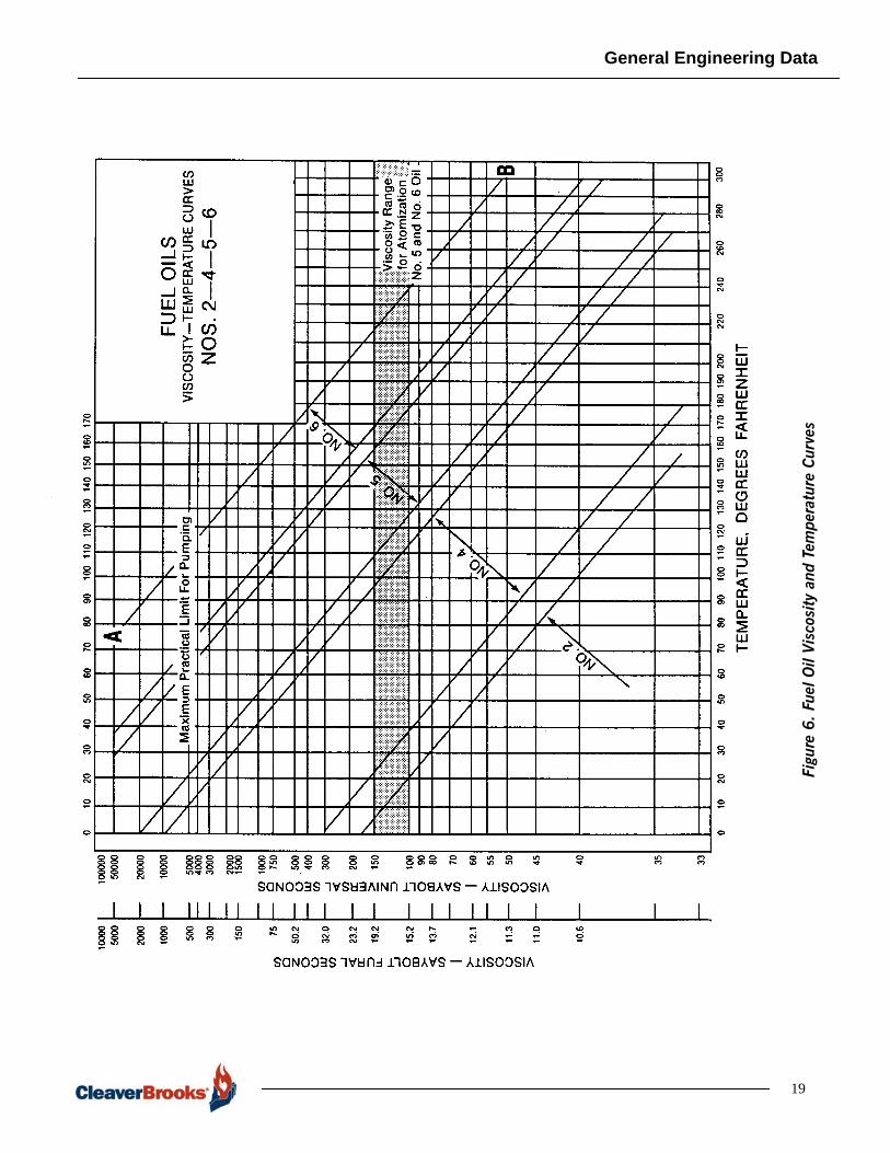
To use these tables, select the table with the appropriate viscosity for the oil that isbeing used. (An oil viscosity chart is provided later in this section in Figure 6.)Select the line corresponding to the required flow, and the column corresponding tothe nominal pipe size. The intersection will give the pressure drop in psi per 100feet of equivalent pipe length.
For example, a typical No. 2 fuel oil has a viscosity 40 SSU. A 500 hp boilerrequires up to 115 gallons per hour of No. 2 oil. Using Table 2, and specifying a 1-inch nominal pipe size, gives 0.1 psi pressure drop at 100 gph, and 0.2 at 150gph. Linear interpolation gives 0.13 psi pressure drop per 100 equivalent feet ofpipe. Note that heavy oils require a return line, which increases total flowrequirements.
4

General Engineering Data
Figu
re 1
. St
eam
Pip
e Ch
art
- Pr
essu
re D
rop
5

General Engineering Data
6
Figu
re 2
. Pre
ssur
e D
rop
for
Wat
er

General Engineering Data
Table 1. Gas Line Capacities
7
INITIAL GAS
PRESSURE
TOTAL PRESSDROP
GAS LINE CAPACITIES (CU-FT/HR THROUGH 100 FT LENGTH)
DIAMETER OF PIPE IN INCHES
1/2 3/4 1 1-1/4 1-1/2 2 2-1/2 3 4 5 6 8
4” water 0.2” 23 52 104 230 358 724 1180 2150 4510 8210 13400 273005” water 0.25” 26 58 117 257 400 811 1320 2410 5050 9190 14900 306006” water 0.30” 28 64 128 282 439 889 1450 2640 5540 10100 16400 335007” water 0.35” 31 69 139 305 475 962 1570 2860 5990 10900 17700 363008” water 0.40” 33 74 148 327 508 1030 1680 3060 6410 11700 19000 388009” water 0.45” 35 79 158 347 540 1090 1780 3250 6810 12400 20200 4120010” water 0.50” 37 83 166 366 569 1150 1880 3430 7180 13100 21300 4350011” water 0.55” 38 87 175 385 598 1210 1980 3600 7550 13700 22300 4570012” water 0.6” 40 91 183 402 625 1280 2060 3760 7890 14300 23300 477001/2 psi .025 psi 43 98 197 433 673 1360 2220 4050 8590 15400 25100 514003/4 psi .038 psi 53 121 243 534 831 1680 2750 5000 10500 19100 31100 635001 psi .050 psi 62 141 282 622 967 1960 3190 5820 12200 22200 36100 738001-1/4 psi .062 psi 70 159 319 702 1090 2210 3600 6570 13800 25000 40800 833001-1/2 psi .075 psi 77 175 351 773 1200 2440 3970 7240 15200 27600 44900 918001-3/4 psi .088 psi 84 191 382 842 1310 2650 4320 7870 16500 30000 48900 999002 psi .100 psi 91 205 412 906 1410 2850 4660 8480 17800 32300 52600 1080002-1/2 psi .125 psi 103 233 467 1030 1600 3240 5280 9620 20200 36700 59000 1220003 psi .150 psi 114 259 519 1140 1780 3600 5870 10700 22400 40800 66300 1360003-1/2 psi .175 psi 125 283 568 1250 1940 3940 6420 11700 24500 44600 72600 1480004 psi .200 psi 135 307 615 1350 2110 4270 6960 12700 26600 48300 78700 1610004-1/2 psi .225 psi 146 330 661 1460 2260 4580 7480 13600 28500 51900 84500 1730005 psi .250 psi 155 352 706 1550 2420 4890 7980 14500 30500 55400 90200 1840006 psi .300 psi 174 395 792 1740 2710 5490 8960 16300 34200 62200 101000 2070008 psi .400 psi 211 477 957 2110 3280 6640 10800 19700 41300 75200 122000 25000010 psi .500 psi 246 556 1120 2460 3820 7730 12600 23000 48200 87600 143000 292000For total lengths other than 100 ft, multiply the capacity shown in the table by the factor corresponding to the desired length as follows:
Length of pipe in ft 10 15 25 50 100 150 200 250 300 350 400 500Multiplier 3.16 2.58 2.00 1.41 1.00 .817 .707 .632 .577 .535 .500 .447For pressures and diameters not shown, consult you local Cleaver-Brooks authorized representative.
This table shows gas flow capacities of pipes from 1/2” to 8” diameter, based upon a pressure drop of 5% of the initial gas pressure for 100-ft. length of pipe. Turbulent flow is assumed, hence the non-linear ratio of length to capacity.

General Engineering Data
Table 2. Oil Piping Pressure Drop (Viscosity = 40 SSU and Specific Gravity = 0.9)
8
FUEL OIL FLOW RATE (GPH)
NOMINAL PIPE SIZE (INCHES)
0.5 0.75 1 1.5 2 2.5 3 4
25 0.3 0.1 0.0* 0.01 0.00* 0.001 0.000* 0.000*50 0.6 0.2 0.1 0.01 0.00 0.002 0.001 0.000*75 0.9 0.3 0.1 0.02 0.01 0.003 0.001 0.000*100 1.1 0.4 0.1 0.03 0.01 0.005 0.002 0.001150 3.6 0.9 0.2 0.04 0.01 0.007 0.003 0.001200 6.0 1.6 0.5 0.05 0.02 0.009 0.004 0.001250 8.9 2.3 0.7 0.06 0.02 0.011 0.005 0.002300 12.3 3.2 1.0 0.13 0.03 0.014 0.006 0.002400 20.3 5.3 1.7 0.22 0.007 0.018 0.008 0.003500 30.5 7.9 2.5 0.32 0.10 0.042 0.010 0.003600 42.2 11.0 3.5 0.45 0.13 0.058 0.020 0.004700 55.6 14.5 4.6 0.59 0.18 0.076 0.027 0.007
NOTE: Pressure Drop (psig) per 100 equivalent ft of pipe for a fuel oil viscosity of 40 SSU, specific gravity of 0.9* Negligible pressure drop.
Figure 1. Oil Piping Pressure Drop (Viscosity = 100 SSU and Specific Gravity = 0.94)Table 3. Oil Piping Pressure Drop (Viscosity = 100 SSU and Specific Gravity = 0.94)
FUEL OIL FLOW RATE (GPH)
NOMINAL PIPE SIZE (INCHES)
0.5 0.75 1 1.5 2 2.5 3 4
25 3.9 1.3 0.5 0.1 0.03 0.02 0.007 0.00250 7.8 2.5 1.0 0.2 0.06 0.03 0.013 0.00475 11.6 3.8 1.4 0.3 0.10 0.05 0.020 0.007100 15.5 5.0 1.9 0.3 0.13 0.06 0.026 0.009150 23.3 7.6 2.9 0.5 0.19 0.09 0.039 0.013200 31.1 10.1 3.8 0.7 0.25 0.13 0.052 0.018250 38.8 12.6 4.8 0.9 0.32 0.16 0.066 0.022300 46.6 15.1 5.8 1.0 0.38 0.19 0.079 0.027400 62.1 20.2 7.7 1.4 0.51 0.25 0.10 0.035500 77.6 25.2 9.6 1.7 0.64 0.31 0.13 0.044600 93.2 30.2 11.5 2.1 0.76 0.38 0.16 0.053700 108.7 35.3 13.4 2.4 0.89 0.44 0.18 0.062
NOTE: Pressure Drop (psig) per 100 equivalent ft of pipe for a fuel oil viscosity of 100 SSU, specific gravity of 0.94
Table 4. Oil Piping Pressure Drop (Viscosity = 500 SSU and Specific Gravity = 0.94)
FUEL OIL FLOW RATE (GPH)
NOMINAL PIPE SIZE (INCHES)
0.5 0.75 1 1.5 2 2.5 3 4
25 7.8 2.5 1.0 0.2 0.06 0.03 0.013 0.00450 15.6 5.1 1.9 0.3 0.13 0.06 0.026 0.00975 23.5 7.6 2.9 0.5 0.19 0.019 0.040 0.013100 31.3 10.2 3.9 0.7 0.26 0.13 0.053 0.018150 46.9 15.2 5.8 1.0 0.38 0.19 0.079 0.027200 62.6 20.3 7.7 1.4 0.51 0.25 0.106 0.036250 78.2 25.4 9.7 1.7 0.64 0.32 0.132 0.045300 93.9 30.5 11.6 2.1 0.77 0.38 0.159 0.053400 125.1 40.6 15.5 2.8 1.03 0.50 0.21 0.071500 156.4 50.8 19.3 3.5 1.28 0.63 0.26 0.089600 187.7 69.9 23.2 4.2 1.54 0.76 0.32 0.107700 219.0 71.1 27.1 4.9 1.80 0.88 0.37 0.125
NOTE: Pressure Drop (psig) per 100 equivalent ft of pipe for a fuel oil viscosity of 500 SSU, specific gravity of 0.94

General Engineering Data
Table 5. Oil Piping Pressure Drop (Viscosity = 1000 SSU and Specific Gravity = 0.96)
FUEL OIL FLOW RATE (GPH)
NOMINAL PIPE SIZE (INCHES)
0.5 0.75 1 1.5 2 2.5 3 4
25 16.0 5.2 2.0 0.4 0.13 0.06 0.027 0.009
50 32.0 10.4 4.0 0.7 0.26 0.13 0.054 0.018
75 48.0 15.6 5.9 1.1 0.39 0.19 0.081 0.027
100 64.0 20.8 7.9 1.4 0.52 0.26 0.108 0.036
150 96.0 31.2 11.9 2.1 0.79 0.39 0.162 0.055
200 128.0 41.6 15.8 2.9 1.05 .052 0.216 0.073
250 160.1 52.0 19.8 3.6 1.31 0.64 0.270 0.091
300 192.1 62.4 23.7 4.3 1.57 0.77 0.324 0.109
400 256.1 83.1 31.7 5.7 2.10 1.03 0.43 0.146
500 320.1 103.9 39.6 7.1 2.62 1.29 0.54 0.182
600 384.1 124.7 47.5 8.6 3.15 1.55 0.65 0.219
700 448.1 145.5 55.4 10.0 3.67 1.81 0.76 0.255
NOTE: Pressure Drop (psig) per 100 equivalent ft of pipe for a fuel oil viscosity of 1000 SSU, specific gravity of 0.96
Table 6. Oil Piping Pressure Drop (Viscosity = 5000 SSU and Specific Gravity = 0.96)
9
FUEL OIL FLOW RATE (GPH)
NOMINAL PIPE SIZE (INCHES)
0.5 0.75 1 1.5 2 2.5 3 4
25 80 26 10 2 1 0.3 0.1 0.05
50 160 52 20 4 1 0.6 0.3 0.09
75 240 78 30 5 2 1.0 0.4 0.14
100 320 104 40 7 3 1.3 0.5 0.18
150 480 156 59 11 4 1.9 0.8 0.27
200 641 208 79 14 5 2.6 1.1 0.36
250 801 260 99 18 7 3.2 1.4 0.46
300 961 312 119 21 8 3.9 1.6 0.55
400 1281 416 158 29 11 5.2 2.2 0.73
500 1601 520 198 36 13 6.5 2.7 0.91
600 1922 624 238 43 16 7.7 3.2 1.09
700 2242 728 277 50 18 9.0 3.8 1.28
NOTE: Pressure Drop (psig) per 100 equivalent ft of pipe for a fuel oil viscosity of 5000 SSU, specific gravity of 0.96
General Engineering Data
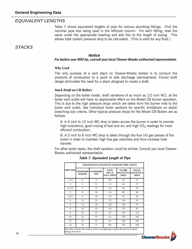
EQUIVALENT LENGTHSTable 7 shows equivalent lengths of pipe for various plumbing fittings. Find thenominal pipe size being used in the leftmost column. For each fitting, read thevalue under the appropriate heading and add this to the length of piping. Thisallows total system pressure drop to be calculated. (This is valid for any fluid.)
STACKS
NoticeFor boilers over 800 hp, consult your local Cleaver-Brooks authorized representative.
Why UsedThe only purpose of a vent stack on Cleaver-Brooks boilers is to conduct theproducts of combustion to a point of safe discharge (atmosphere). Forced draftdesign eliminates the need for a stack designed to create a draft.
Stack Draft on CB BoilersDepending on the boiler model, draft variations of as much as 1/2 inch W.C. at theboiler vent outlet will have no appreciable effect on the Model CB burner operation.This is due to the high pressure drops which are taken from the burner inlet to theboiler vent outlet. See individual boiler sections for specific limitations on stack/breeching size criteria. Other typical pressure drops for the Model CB Boilers are asfollows:
A. A 4 inch to 12 inch WC drop is taken across the burner in order to provide high turbulence, good mixing of fuel and air, and high CO2 readings for most efficient combustion,
B. A 2 inch to 6 inch WC drop is taken through the four (4) gas passes of the boiler in order to maintain high flue gas velocities and thus increase heat transfer.
For other boiler types, the draft variation could be similar. Consult you local Cleaver-Brooks authorized representative.
10
Table 7. Equivalent Length of Pipe
PIPE SIZE
EQUIVALENT LENGTH OF STRAIGHT PIPE (FEET)
STANDARD ELBOW
STANDARD TEE
GATE VALV E
FULL OPEN
GLOBE VALVE FULL
OPEN
ANGLE VALVE FULL
OPEN
1-1/2 4 9 0.9 41 21
2 5 11 1.2 54 27
2-/1/2 6 13 1.4 64 32
3 8 16 1.6 80 40
3-1/2 9 18 2.0 91 45
4 11 21 2.2 110 55
5 13 26 2.8 140 70
6 16 32 3.4 155 81
8 20 42 4.5 210 110
10 25 55 5.5 270 140
12 30 65 6.5 320 160
14 35 75 8.0 370 190
This table contains the number of feet of straight pipe usually allowed for standard fittings and valves.

General Engineering Data
If the stack height is over 150 feet or if an extremely large breeching and stackcombination cause excessive draft, a simple barometric damper can be located inthe breeching close to the stack or chimney. This damper should only be consideredafter burner adjustment problems have been experienced and are serious enough towarrant corrective action.
Automatic or special draft controls are not required and are not recommended foruse with Cleaver-Brooks boilers.
Stack LocationAn off-set type stack connection to the stub vent on the boiler is preferred andrecommended. A direct vertical connection can also be made, if required. A typicalstack location diagram is shown in Figure 3.
Stack CondensationThe amount of condensation in the stack will vary with the type of fuel and with thestack gas temperature. Normally, the temperature of the flue gas leaving the boileris higher than the temperature of the steam or the water in the boiler.
Stack condensation is most likely to occur on heating boiler installations where lightloads and intermittent firing cause a cool stack condition, which results incondensation of the water vapor in the flue gas. This condensed water acceleratescorrosion of steel stacks or breechings.
The following items should be considered when planning to keep stackcondensation to a minimum:
A. The boiler should be sized as close as possible to the true heat load. Oversized boilers should be avoided.
B. Masonry stacks have better heat holding characteristics than steel stacks.
C. When steel stacks are used, stack insulation will help prevent heat loss.
D. An off-set stack (recommended) with bottom clean-out and drain connection will prevent any condensed water from draining back into the boiler.
Stack WeightBoiler vent outlets will withstand a maximum direct vertical load of 2,000 pounds.This loading must include the effect of wind and guy wires.
Stack ConstructionThe stack can be terminated several feel above the top of the roof. (State and localcodes may govern the stack height above the roof.) If down drafts are unavoidable,the stack outlet can be provided with a ventilator such as the Breidert Air-X-Hausteror equivalent. See Figure 4 for typical stack construction details.
Stack MaterialMinimum 12 gauge steel is recommended for stack sections. If the stack will beinaccessible, the use of a non-corrosive material (e.g. glass lining) should beconsidered.
A rain cap or hood should be used at the top of the stack to minimize the entranceof rain or snow. See Figure 5 for typical rain cap details.
11

General Engineering Data
VERTICAL STACK CONNECTION OFFSET STACK CONNECTION (RECOMMENDED)
STACK TIGHT-SEALCLEANOUT
CLEANOUT
DRAIN CONNECTION
STACK
Figure 3. Typical Stack Locations
BOILER HPSTACK
DIAMETER (IN.)
A (IN.) B (IN.)
C (IN.)
D (IN.)
15-20 6 5 12 3 325-40, 50A 8 6 16 4 450-60 10 8 20 5 570-100A, 125A 12 9 24 6 6125-200 16 12 32 8 8250-350 20 15 40 10 10400-600 24 18 48 12 12700-800 24 21 48 12 12
BOILER HP STACK DIAMETER (IN.) A (IN.) B
(IN.)C
(IN.)
15-20 6 15 15 12
25-40, 50A 8 20 20 16
50-60 10 25 25 20
70-100A, 125A 12 30 30 24
125-200 16 40 40 32
250-350 20 50 50 40
400-800 24 60 60 48
RAIN CAP
AS REQUIREDBY LOCAL CODE
STACK DIA.
TOP OR ROOF
2’-0 MIN
A
B
C
A
B
C
D
STACKDIA
Figure 4. Typical Stack Construction
12
Figure 5. Rain Cap Details

General Engineering Data
Stack/Breeching Size CriteriaThe design of the stack and breeching system must provide a draft at the boileroutlet(s) which is within the required limits. Consideration must be given tooperation variations (including number of boilers), purge cycles, outside wind andair conditions, and the impact of other variables that may impact draft conditions.Safe and reliable burner performance requires good stack design.See Table 8 andfurther detail in the individual boiler sections.
Stack and breeching sizes should always be provided by a reputable stack supplierwho will design the stack and breeching system based on the required systemlayout. Your local Cleaver-Brooks authorized representative is capable of assisting inyour evaluation of the stack/breeching design.
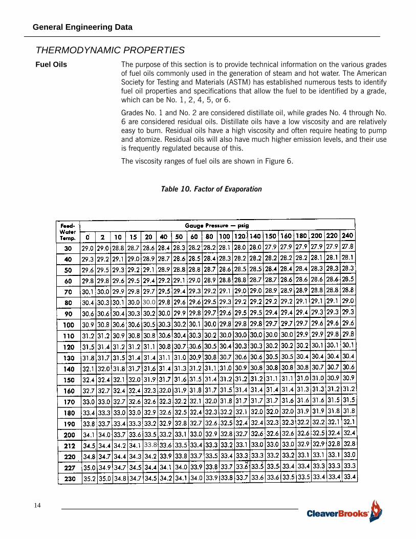
FACTORS OF EVAPORATIONThe factor of evaporation is used to adjust rated boiler output (from and at 212 °F)to actual job or operating conditions. Available feedwater temperature and expectedboiler operating pressure (psig) affect the boiler output ratings which are based on“from and at 212 °F.”
Example: A boiler is to have an output of 3060 pounds of steam per hour whenoperating at 10 psig with feedwater at 100 °F. What should the boiler rating be onthe basis of “from and at 212 °F.”
Referring to Table 10, at 100 °F and 10 psig, the following factors can be obtained:30.6 pounds of steam per boiler horsepower. This factor is used to convert the“from and at 212 °F” rating basis:
3060 ÷ 30.6 = 100 hp rated boiler should be selected.
Table 8. Single Boiler Vent or Stack Diameter
BOILER HPSTACK DIAMETER
Same as Boiler Vent Outlet Size (Inches OD)
15-20 625-40, 50A 850-60 1070-100, 100A, 125A 12
125-200 16250-350 20400-800 24
Table 9. Multiple Boilers - Common Breeching and Stack
13
BOILER HP
MINIMUM RECOMMENDED STACK DIAMETERA
NUMBER OF BOILERS
2 3 4
100 FT
200 FT
100 FT
200 FT
100 FT
200 FT
15-20 9" 10" 10" 12" 11" 12"
25-40 11" 12" 13" 14" 14" 16"
50A, 50-60 13" 14" 15" 16" 17" 18"
70-100. 100A
16" 17" 19" 20" 21" 23"
125-200 21" 22" 24" 26" 28" 30"
250-350 26" 28" 32" 34" 34" 40"
400-600 32" 34" 38" 40" 421" 46"
700-800 38" 42" 44" 48" 48" 52"
Notes:A. No barometric damper required.
General Engineering Data
14
Table 10. Factor of Evaporation
THERMODYNAMIC PROPERTIESFuel Oils The purpose of this section is to provide technical information on the various grades
of fuel oils commonly used in the generation of steam and hot water. The AmericanSociety for Testing and Materials (ASTM) has established numerous tests to identifyfuel oil properties and specifications that allow the fuel to be identified by a grade,which can be No. 1, 2, 4, 5, or 6.
Grades No. 1 and No. 2 are considered distillate oil, while grades No. 4 through No.6 are considered residual oils. Distillate oils have a low viscosity and are relativelyeasy to burn. Residual oils have a high viscosity and often require heating to pumpand atomize. Residual oils will also have much higher emission levels, and their useis frequently regulated because of this.
The viscosity ranges of fuel oils are shown in Figure 6.
30.0
33.8

General Engineering Data
Fuel Oil Specifications
The limits on fuel oil properties are shown in Table 11, Table 12, and Table 13.Definitions of these properties are discussed next.
Ultimate Analysis - Ultimate analysis is a statement of the quantities of the variouselements of which a substance is composed. For fuel oils, this will likely statehigher heating values and specific gravity in addition to the percentages by weightof each element.
Flash Point - The flash point of a fuel oil is an indication of the maximumtemperature at which it can be stored and handled without serious fire hazard. Theminimum permissible flash point is usually regulated by federal, state or municipallaws and is based on accepted practice in handling and use.
Pour Point - The pour point is an indication of the lowest temperature at which a fuel oil can bestored and still be capable of flowing under very low forces. The pour point is prescribed inaccordance with the conditions of storage and use. Higher pour point fuels are permissiblewhere heated storage and adequate piping facilities are provided. An increase inpour point can occur when residual fuel oils are subjected to cyclic temperaturevariations that can occur in the course of storage or when the fuel is preheated andreturned to storage tanks. To predict these properties, Test Method D 3245 may berequired.
Water and Sediment - Appreciable amounts of water and sediments in a fuel oiltend to cause fouling of facilities for handling it, and cause trouble in burnermechanisms. Sediment may accumulate in storage tanks and on filter screens orburner parts, resulting in obstructions to flow of oil from the tank to the burner.Water in distillate fuels can cause corrosion of tanks and equipment, and can causeemulsions in residual fuels.
Carbon Residue - The carbon residue of a fuel is a measure of the carbonaceousmaterial left after all the volatile components are vaporized in the absence of air. Itis a rough approximation of the tendency of a fuel to form deposits in vaporizingburners, such as pot-type and sleeve burners, where the fuel is vaporized in an air-deficient atmosphere.
To obtain measurable values of carbon residue in the lighter distillate fuel oils, it isnecessary to distill the oil to remove 90% of it in accordance with Section 9 of TestMethod D 524, and determine the carbon residue concentrated in the remaining10% bottoms.
Ash - The amount of ash is the quantity of noncombustible material in an oil.Excessive amounts can indicate the presence of materials that cause high wear ofburner pumps and valves, and contribute to deposits on boiler heating surfaces.
Table 11. Typical Units for Fuels
15
ITEM GROSS HEATING VALUES
No. 2 Oil 140,000 Btu/gal.
No 5 Oil 148,000 Btu/gal.
No. 6 Oil 150,000 Btu/gal.
1 Therm 100,000 Btu
1 kW 3,413 Btu
General Engineering Data
16
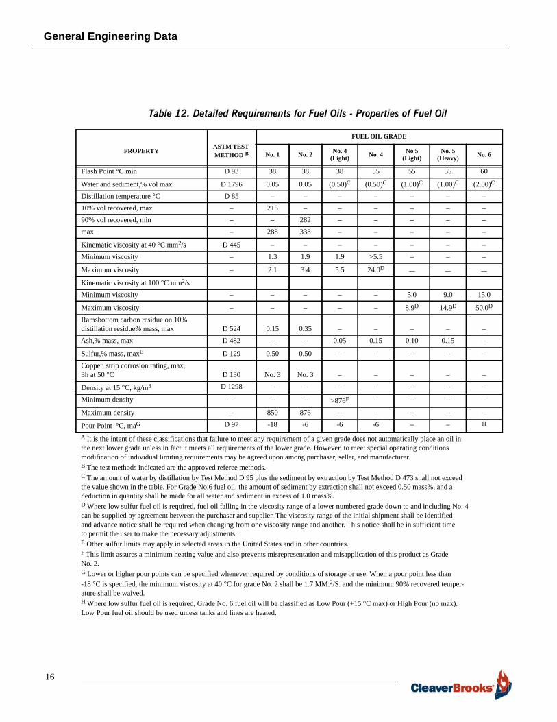
Table 12. Detailed Requirements for Fuel Oils - Properties of Fuel Oil
PROPERTY ASTM TEST METHOD B
FUEL OIL GRADE
No. 1 No. 2 No. 4 (Light) No. 4 No 5
(Light)No. 5
(Heavy) No. 6
Flash Point °C min D 93 38 38 38 55 55 55 60
Water and sediment,% vol max D 1796 0.05 0.05 (0.50)C (0.50)C (1.00)C (1.00)C (2.00)C
Distillation temperature °C D 85 – – – – – – –10% vol recovered, max – 215 – – – – – –90% vol recovered, min – – 282 – – – – –max – 288 338 – – – – –
Kinematic viscosity at 40 °C mm2/s D 445 – – – – – – –Minimum viscosity – 1.3 1.9 1.9 >5.5 – – –
Maximum viscosity – 2.1 3.4 5.5 24.0D — — —
Kinematic viscosity at 100 °C mm2/sMinimum viscosity – – – – – 5.0 9.0 15.0
Maximum viscosity – – – – – 8.9D 14.9D 50.0D
Ramsbottom carbon residue on 10% distillation residue% mass, max D 524 0.15 0.35 – – – – –Ash,% mass, max D 482 – – 0.05 0.15 0.10 0.15 –
Sulfur,% mass, maxE D 129 0.50 0.50 – – – – –Copper, strip corrosion rating, max, 3h at 50 °C D 130 No. 3 No. 3 – – – – –
Density at 15 °C, kg/m3 D 1298 – – – – – – –
Minimum density – – – >876F – – – –
Maximum density – 850 876 – – – – –
Pour Point °C, maG D 97 -18 -6 -6 -6 – – H
A It is the intent of these classifications that failure to meet any requirement of a given grade does not automatically place an oil in the next lower grade unless in fact it meets all requirements of the lower grade. However, to meet special operating conditions modification of individual limiting requirements may be agreed upon among purchaser, seller, and manufacturer.B The test methods indicated are the approved referee methods. C The amount of water by distillation by Test Method D 95 plus the sediment by extraction by Test Method D 473 shall not exceed the value shown in the table. For Grade No.6 fuel oil, the amount of sediment by extraction shall not exceed 0.50 mass%, and a deduction in quantity shall be made for all water and sediment in excess of 1.0 mass%.D Where low sulfur fuel oil is required, fuel oil falling in the viscosity range of a lower numbered grade down to and including No. 4 can be supplied by agreement between the purchaser and supplier. The viscosity range of the initial shipment shall be identified and advance notice shall be required when changing from one viscosity range and another. This notice shall be in sufficient time to permit the user to make the necessary adjustments.E Other sulfur limits may apply in selected areas in the United States and in other countries.F This limit assures a minimum heating value and also prevents misrepresentation and misapplication of this product as Grade No. 2.G Lower or higher pour points can be specified whenever required by conditions of storage or use. When a pour point less than -18 °C is specified, the minimum viscosity at 40 °C for grade No. 2 shall be 1.7 MM.2/S. and the minimum 90% recovered temper-ature shall be waived.H Where low sulfur fuel oil is required, Grade No. 6 fuel oil will be classified as Low Pour (+15 °C max) or High Pour (no max).Low Pour fuel oil should be used unless tanks and lines are heated.
General Engineering Data
GRADE OF FUEL OIL FLASH
POINT °F MIN
POUR POINT °F MAX
WATER & SEDIMENT
% MAX
CARBON RESIDUE ON 10%
RESIDUUM% MAX
ASH% MAX
DISTILLATION TEMPERATURES, °F
10% POINT MAX
90% POINT MAX
END POINT MAX
1. Distillate oil intended for vaporizing pot-type burners and other burners requiring this grade.
100or
legal
0 trace 0.15 – 420 – 625
2. A distillate oil for general purpose domestic heating for use in burners not requiring No. 1.
100or
legal
20 0.10 0.35 – - 675 –
4. An oil for burner installations not equipped with preheating facilities.
130or
legal
20 0.50 – 0.10 – – –
5.A residual type oil for burner installations equipped with pre-heating facilities.
130or
legal
– 1.00 – 0.10 – – –
6.An oil for use in burners equipped with preheaters per-mitting a high viscosity fuel,
130or
legal
– 2.00 – – – – –
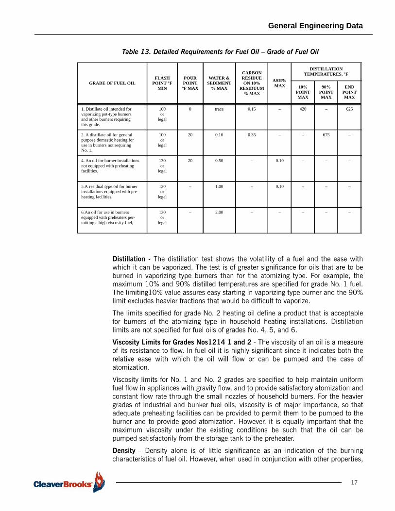
Distillation - The distillation test shows the volatility of a fuel and the ease withwhich it can be vaporized. The test is of greater significance for oils that are to beburned in vaporizing type burners than for the atomizing type. For example, themaximum 10% and 90% distilled temperatures are specified for grade No. 1 fuel.The limiting10% value assures easy starting in vaporizing type burner and the 90%limit excludes heavier fractions that would be difficult to vaporize.
The limits specified for grade No. 2 heating oil define a product that is acceptablefor burners of the atomizing type in household heating installations. Distillationlimits are not specified for fuel oils of grades No. 4, 5, and 6.
Viscosity Limits for Grades Nos1214 1 and 2 - The viscosity of an oil is a measureof its resistance to flow. In fuel oil it is highly significant since it indicates both therelative ease with which the oil will flow or can be pumped and the case ofatomization.
Viscosity limits for No. 1 and No. 2 grades are specified to help maintain uniformfuel flow in appliances with gravity flow, and to provide satisfactory atomization andconstant flow rate through the small nozzles of household burners. For the heaviergrades of industrial and bunker fuel oils, viscosity is of major importance, so thatadequate preheating facilities can be provided to permit them to be pumped to theburner and to provide good atomization. However, it is equally important that themaximum viscosity under the existing conditions be such that the oil can bepumped satisfactorily from the storage tank to the preheater.
Density - Density alone is of little significance as an indication of the burningcharacteristics of fuel oil. However, when used in conjunction with other properties,
Table 13. Detailed Requirements for Fuel Oil – Grade of Fuel Oil
17

General Engineering Data
it is of value in mass-volume relationships and in calculating the specific energy(heating value) of an oil.
Corrosion - The corrosion test serves to indicate the presence or absence ofmaterials that could corrode copper, brass, and bronze components of the fuelsystem. This property is specified only for Nos. 1 and 2 distillate fuel oils.
Limited sulfur content of fuel oil can be required to meet federal, state, or locallegislation or regulations.
Nitrogen - Nitrogen oxide emission regulations have been imposed on certaincombustion facilities as a function of fuel nitrogen content. For purposes of theseregulations, distillate fuels, low nitrogen residual fuels, and high nitrogen residualfuels have been defined by their nitrogen content. Installations are required to meetdifferent emission standards according to the classification of the fuel being used.When regulations require such a distinction to be made, fuel nitrogen specificationscan be needed in the contractual agreement between the purchaser and thesupplier.
18
General Engineering Data
Figu
re 6
. Fue
l Oil
Visc
osity
and
Tem
pera
ture
Cur
ves
19

General Engineering Data
20
Water The relevant properties of water are shown in Table 14.
Table 14. Thermal Properties of Water

General Engineering Data
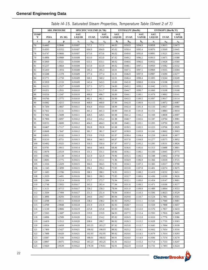
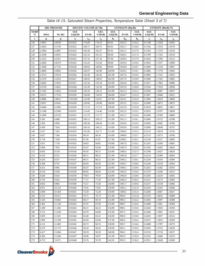
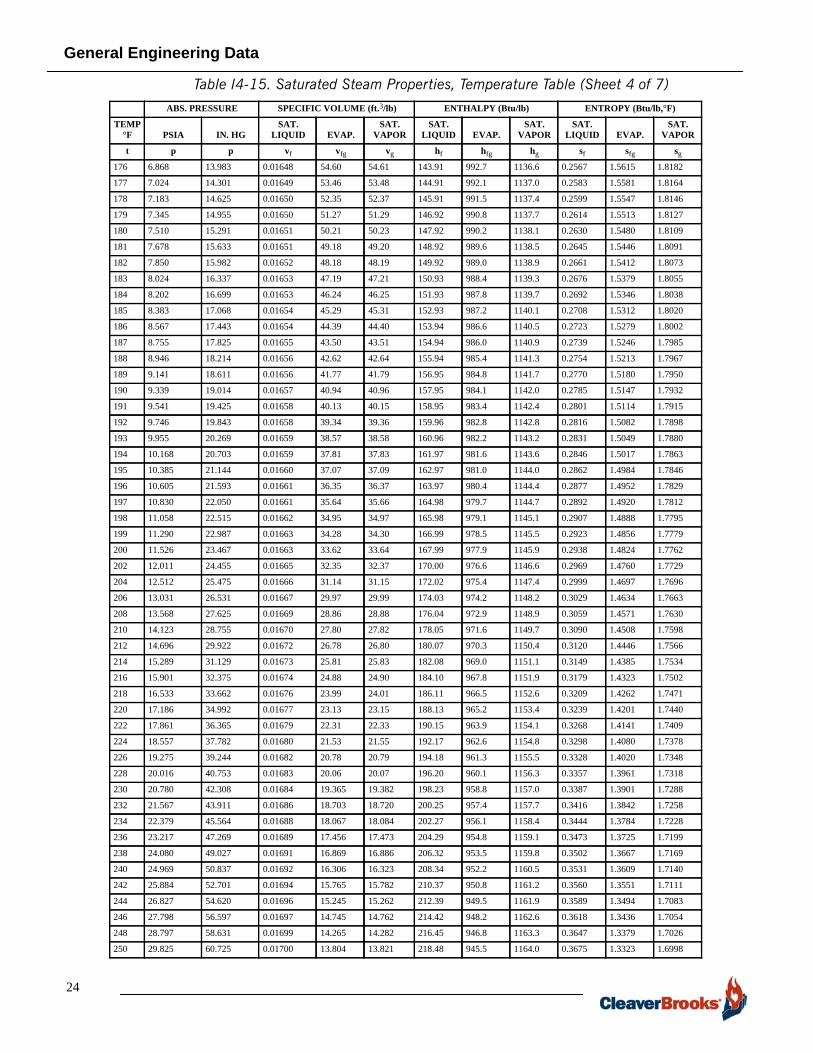
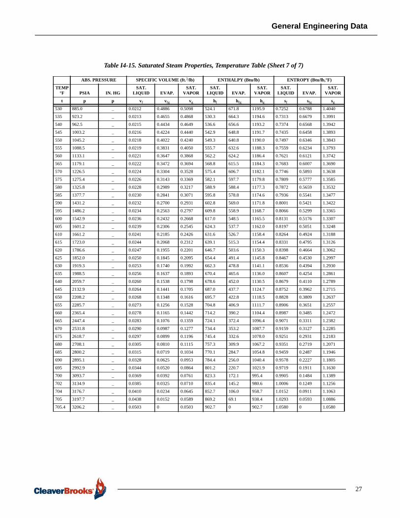
Steam Steam properties are shown in Table 15 and Table 16.
ABS. PRESSURE SPECIFIC VOLUME (ft.3/lb) ENTHALPY (Btu/lb) ENTROPY (Btu/lb,°F)
TEMP °F PSIA IN. HG
SAT. LIQUID EVAP.
SAT. VAPOR
SAT. LIQUID EVAP.
SAT. VAPOR
SAT.LIQUID EVAP.
SAT. VAPOR
t p p vf vfg vg hf hfg hg sf sfg sg
32 0.08854 0.1803 0.01602 3306 3306 0.00 1075.8 1075.8 0.0000 2.1877 2.1877
33 0.09223 0.1878 0.01602 3180 3180 1.01 1075.2 1076.2 0.0020 2.1821 2.1841
34 0.09603 0.1955 0.01602 3061 3061 2.02 1074.7 1076.7 0.0041 2.1764 2.1805
35 0.09995 0.2035 0.01602 2947 2947 3.02 1074.1 1077.1 0.0061 2.1709 2.1770
36 0.10401 0.2118 0.01602 2837 2837 4.03 1073.6 1077.6 0.0081 2.1654 2.1735
37 0.10821 0.2203 0.01602 2732 2732 5.04 1073.0 1078.0 0.0102 2.1598 2.1700
38 0.11256 0.2292 0.01602 2632 2632 6.04 1072.4 1078.4 0.0122 2.1544 2.1666
39 0.11705 0.2383 0.01602 2536 2536 7.04 1071.9 1078.9 0.0142 2.1489 2.1631
40 0.12170 0.2478 0.01602 2444 2444 8.05 1071.3 1079.3 0.0162 2.1435 2.1597
41 0.12652 0.2576 0.01602 2356 2356 9.05 1070.7 1079.7 0.0182 2.1381 2.1563
42 0.13150 0.2677 0.01602 2271 2271 10.05 1070.1 1080.2 0.0202 2.1327 2.1529
43 0.13665 0.2782 0.01602 2190 2190 11.06 1069.5 1080.6 0.0222 2.1274 2.1496
44 0.14199 0.2891 0.01602 2112 2112 12.06 1068.9 1081.0 0.0242 2.1220 2.1462
45 0.14752 0.3004 0.01602 2036.4 2036.4 13.06 1068.4 1081.5 0.0262 2.1167 2.1429
46 0.15323 0.3120 0.01602 1964.3 1964.3 14.06 1067.8 1081.9 0.0282 2.1113 2.1395
47 0.15914 0.3240 0.01603 1895.1 1895.1 15.07 1067.3 1082.4 0.0302 2.1060 2.1362
48 0.16525 0.3364 0.01603 1828.6 1828.6 16.07 1066.7 1082.8 0.0321 2.1008 2.1329
49 0.17157 0.3493 0.01603 1764.7 1764.7 17.07 1066.1 1083.2 0.0341 2.0956 2.1297
50 0.17811 0.3626 0.01603 1703.2 1703.2 18.07 1065.6 1083.7 0.0361 2.0903 2.1264
51 0.18486 0.3764 0.01603 1644.2 1644.2 19.07 1065.0 1084.1 0.0380 2.0852 2.1232
52 0.19182 0.3906 0.01603 1587.6 1587.6 20.07 1064.4 1084.5 0.0400 2.0799 2.1199
53 0.19900 0.4052 0.01603 1533.3 1533.3 21.07 1063.9 1085.0 0.0420 2.0747 2.1167
54 0.20642 0.4203 0.01603 1481.0 1481.0 22.07 1063.3 1085.4 0.0439 2.0697 2.1136
55 0.2141 0.4359 0.01603 1430.7 1430.7 23.07 1062.7 1085.8 0.0459 2.0645 2.1104
56 0.2220 0.4520 0.01603 1382.4 1382.4 24.06 1062.2 1086.3 0.0478 2.0594 2.1072
57 0.2302 0.4686 0.01603 1335.9 1335.9 25.06 1061.6 1086.7 0.0497 2.0544 2.1041
58 0.2386 0.4858 0.01604 1291.1 1291.1 26.06 1061.0 1087.1 0.0517 2.0493 2.1010
59 0.2473 0.5035 0.01604 1248.1 1248.1 27.06 1060.5 1087.6 0.0536 2.0443 2.0979
60 0.2563 0.5218 0.01604 1206.6 1206.7 28.06 1059.9 1088.0 0.0555 2.0393 2.0948
61 0.2655 0.5407 0.01604 1166.8 1166.8 29.06 1059.3 1088.4 0.0574 2.0343 2.0917
62 0.2751 0.5601 0.01604 1128.4 1128.4 30.05 1058.8 1088.9 0.0593 2.0293 2.0886
63 0.2850 0.5802 0.01604 1091.4 1091.4 31.05 1058.2 1089.3 0.0613 2.0243 2.0856
64 0.2951 0.6009 0.01605 1055.7 1055.7 32.05 1057.6 1089.7 0.0632 2.0194 2.0826
65 0.3056 0.6222 0.01605 1021.4 1021.4 33.05 1057.1 1090.2 0.0651 2.0145 2.0796
66 0.3164 0.6442 0.01605 988.4 988.4 34.05 1056.5 1090.6 0.0670 2.0096 2.0766
67 0.3276 0.6669 0.01605 956.6 956.6 35.05 1056.0 1091.0 0.0689 2.0047 2.0736
68 0.3390 0.6903 0.01605 925.9 925.9 36.04 1055.5 1091.5 0.0708 1.9998 2.0706
69 0.3509 0.7144 0.01605 896.3 896.3 37.04 1054.9 1091.9 0.0726 1.9950 2.0676
70 0.3631 0.7392 0.01606 867.8 867.9 38.04 1054.3 1092.3 0.0745 1.9902 2.0647
71 0.3756 0.7648 0.01606 840.4 840.4 39.04 1053.8 1092.8 0.0764 1.9854 2.0618
72 0.3886 0.7912 0.01606 813.9 813.9 40.04 1053.2 1093.2 0.0783 1.9805 2.0588
73 0.4019 0.8183 0.01606 788.3 788.4 41.03 1052.6 1093.6 0.0802 1.9757 2.0559
74 0.4156 0.8462 0.01606 763.7 763.8 42.03 1052.1 1094.1 0.0820 1.9710 2.0530
75 0.4298 0.8750 0.01607 740.0 740.0 43.03 1051.5 1094.5 0.0839 1.9663 2.0502
Table 15. Saturated Steam Properties, Temperature Table (Sheet 1 of 7)
21
General Engineering Data
22
Table I4-15. Saturated Steam Properties, Temperature Table (Sheet 2 of 7)
76 0.4443 0.9046 0.01607 717.1 717.1 44.03 1050.9 1094.9 0.0858 1.9615 2.0473
77 0.4593 0.9352 0.01607 694.9 694.9 45.02 1050.4 1095.4 0.0876 1.9569 2.0445
78 0.4747 0.9666 0.01607 673.6 673.6 46.02 1049.8 1095.8 0.0895 1.9521 2.0416
79 0.4906 0.9989 0.01608 653.0 653.0 47.02 1049.2 1096.2 0.0913 1.9475 2.0388
80 0.5069 1.0321 0.01608 633.1 633.1 48.02 1048.6 1096.6 0.0932 1.9428 2.0360
81 0.5237 1.0664 0.01608 613.9 613.9 49.02 1048.1 1097.1 0.0950 1.9382 2.0332
82 0.5410 1.1016 0.01608 595.3 595.3 50.01 1047.5 1097.5 0.0969 1.9335 2.0304
83 0.5588 1.1378 0.01609 577.4 577.4 51.01 1046.9 1097.9 0.0987 1.9290 2.0277
84 0.5771 1.1750 0.01609 560.1 560.2 52.01 1046.4 1098.4 0.1005 1.9244 2.0249
85 0.5959 1.2133 0.01609 543.4 543.5 53.00 1045.8 1098.8 0.1024 1.9198 2.0222
86 0.6152 1.2527 0.01609 527.3 527.3 54.00 1045.2 1099.2 0.1042 1.9153 2.0195
87 0.6351 1.2931 0.01610 511.7 511.7 55.00 1044.7 1099.7 0.1060 1.9108 2.0168
88 0.6556 1.3347 0.01610 496.6 496.7 56.00 1044.1 1100.1 0.1079 1.9062 2.0141
89 0.6766 1.3775 0.01610 482.1 482.1 56.99 1043.5 1100.5 0.1097 1.9017 2.0114
90 0.6982 1.4215 0.01610 468.0 468.0 57.99 1042.9 1100.9 0.1115 1.8972 2.0087
91 0.7204 1.4667 0.01611 454.4 454.4 58.99 1042.4 1101.4 0.1133 1.8927 2.0060
92 0.7432 1.5131 0.01611 441.2 441.3 59.99 1041.8 1101.8 0.1151 1.8883 2.0034
93 0.7666 1.5608 0.01611 428.5 428.5 60.98 1041.2 1102.2 0.1169 1.8838 2.0007
94 0.7906 1.6097 0.01612 416.2 416.2 61.98 1040.7 1102.6 0.1187 1.8794 1.9981
95 0.8153 1.6600 0.01612 404.3 404.3 62.98 1040.1 1103.1 0.1205 1.8750 1.9955
96 0.8407 1.7117 0.01612 392.8 392.8 63.98 1039.5 1103.5 0.1223 1.8706 1.9929
97 0.8668 1.7647 0.01612 381.7 381.7 64.97 1038.9 1103.9 0.1241 1.8662 1.9903
98 0.8935 1.8192 0.01613 370.9 370.9 65.97 1038.4 1104.4 0.1259 1.8618 1.9877
99 0.9210 1.8751 0.01613 360.4 360.5 66.97 1037.8 1104.8 0.1277 1.8575 1.9852
100 0.9492 1.9325 0.01613 350.3 350.4 67.97 1037.2 1105.2 0.1295 1.8531 1.9826
101 0.9781 1.9915 0.01614 340.6 340.6 68.96 1036.6 1105.6 0.1313 1.8488 1.9801
102 1.0078 2.0519 0.01614 331.1 331.1 69.96 1036.1 1106.1 0.1330 1.8445 1.9775
103 1.0382 2.1138 0.01614 321.9 321.9 70.96 1035.5 1106.5 0.1348 1.8402 1.9750
104 1.0695 2.1775 0.01615 313.1 313.1 71.96 1034.9 1106.9 0.1366 1.8359 1.9725
105 1.1016 2.2429 0.01615 304.5 304.5 72.95 1034.3 1107.3 0.1383 1.8317 1.9700
106 1.1345 2.3099 0.01615 296.1 296.2 73.95 1033.8 1107.8 0.1401 1.8274 1.9675
107 1.1683 2.3786 0.01616 288.1 288.1 74.95 1033.3 1108.2 0.1419 1.8232 1.9651
108 1.2029 2.4491 0.01616 280.3 280.3 75.95 1032.7 1108.6 0.1436 1.8190 1.9626
109 1.2384 2.5214 0.01616 272.7 272.7 76.94 1032.1 1109.0 0.1454 1.8147 1.9601
110 1.2748 2.5955 0.01617 265.3 265.4 77.94 1031.6 1109.5 0.1471 1.8106 1.9577
111 1.3121 2.6715 0.01617 258.2 258.3 78.94 1031.0 1109.9 0.1489 1.8064 1.9553
112 1.3504 2.7494 0.01617 251.3 251.4 79.94 1030.4 1110.3 0.1506 1.8023 1.9529
113 1.3896 2.8293 0.01618 244.6 244.7 80.94 1029.8 1110.7 0.1524 1.7981 1.9505
114 1.4298 2.9111 0.01618 238.2 238.2 81.93 1029.2 1111.1 0.1541 1.7940 1.9481
115 1.4709 2.9948 0.01618 231.9 231.9 82.93 1028.7 1111.6 0.1559 1.7898 1.9457
116 1.5130 3.0806 0.01619 225.8 225.8 83.93 1028.1 1112.0 0.1576 1.7857 1.9433
117 1.5563 3.1687 0.01619 219.9 219.9 84.93 1027.5 1112.4 0.1593 1.7816 1.9409
118 1.6006 3.2589 0.01620 214.2 214.2 85.92 1026.9 1112.8 0.1610 1.7776 1.9386
119 1.6459 3.3512 0.01620 208.6 208.7 86.92 1026.3 1113.2 0.1628 1.7735 1.9363
120 1.6924 3.4458 0.01620 203.25 203.27 87.92 1025.8 1113.7 0.1645 1.7694 1.9339
121 1.7400 3.5427 0.01621 198.02 198.03 88.92 1025.2 1114.1 0.1662 1.7654 1.9316
122 1.7888 3.6420 0.01621 192.93 192.95 89.92 1024.6 1114.5 0.1679 1.7614 1.9293
123 1.8387 3.7436 0.01622 188.01 188.02 90.91 1024.0 1114.9 0.1696 1.7574 1.9270
124 1.8897 3.8475 0.01622 183.23 183.25 91.91 1023.4 1115.3 0.1714 1.7533 1.9247
125 1.9420 3.9539 0.01622 178.59 178.61 92.91 1022.9 1115.8 0.1731 1.7493 1.9224
ABS. PRESSURE SPECIFIC VOLUME (ft.3/lb) ENTHALPY (Btu/lb) ENTROPY (Btu/lb,°F)
TEMP °F PSIA IN. HG
SAT. LIQUID EVAP.
SAT. VAPOR
SAT. LIQUID EVAP.
SAT. VAPOR
SAT.LIQUID EVAP.
SAT. VAPOR
t p p vf vfg vg hf hfg hg sf sfg sg
General Engineering Data
Table I4-15. Saturated Steam Properties, Temperature Table (Sheet 3 of 7)
126 1.9955 4.0629 0.01623 174.09 174.10 93.91 1022.3 1116.2 0.1748 1.7454 1.9202
127 2.0503 4.1745 0.01623 169.71 169.72 94.91 1021.7 1116.6 0.1765 1.7414 1.9179
128 2.1064 4.2887 0.01624 165.46 165.47 95.91 1021.1 1117.0 0.1782 1.7374 1.9156
129 2.1638 4.4055 0.01624 161.33 161.35 96.90 1020.5 1117.4 0.1799 1.7335 1.9134
130 2.2225 4.5251 0.01625 157.32 157.34 97.90 1020.0 1117.9 0.1816 1.7296 1.9112
131 2.2826 4.6474 0.01625 153.43 153.44 98.90 1019.4 1118.3 0.1833 1.7257 1.9090
132 2.3440 4.7725 0.01626 149.65 149.66 99.90 1018.8 1118.7 0.1849 1.7218 1.9067
133 2.4069 4.9005 0.01626 145.97 145.99 100.90 1018.2 1119.1 0.1866 1.7179 1.9045
134 2.4712 5.0314 0.01626 142.40 142.42 101.90 1017.6 1119.5 0.1883 1.7141 1.9023
135 2.5370 5.1653 0.01627 138.93 138.95 102.90 1017.0 1119.9 0.1900 1.7102 1.9002
136 2.6042 5.3022 0.01627 135.56 135.58 103.90 1016.4 1120.3 0.1917 1.7063 1.8980
137 2.6729 5.4421 0.01628 132.29 132.30 104.89 1015.9 1120.8 0.1934 1.7024 1.8958
138 2.7432 5.5852 0.01628 129.10 129.12 105.89 1015.3 1121.2 0.1950 1.6987 1.8937
139 2.8151 5.7316 0.01629 126.00 126.02 106.89 1014.7 1121.6 0.1967 1.6948 1.8915
140 2.8886 5.8812 ‘0.01629 122.99 123.01 107.89 1014.1 1122.0 0.1984 1.6910 1.8894
141 2.9637 6.0341 0.01630 120.06 120.08 108.89 1013.5 1122.4 0.2000 1.6873 1.8873
142 3.0404 6.1903 0.01630 117.22 117.23 109.89 1012.9 1122.8 0.2016 1.6835 1.8851
143 3.1188 6.3500 0.01631 114.45 114.46 110.89 1012.3 1123.2 0.2033 1.6797 1.8830
144 3.1990 6.5132 0.01631 111.75 111.77 111.89 1011.7 1123.6 0.2049 1.6760 1.8809
145 3.281 6.680 0.01632 109.13 109.15 112.89 1011.2 1124.1 0.2066 1.6722 1.8788
146 3.365 6.850 0.01632 106.58 106.60 113.89 1010.6 1124.5 0.2083 1.6685 1.8768
147 3.450 7.024 0.01633 104.10 104.12 114.89 1010.0 1124.9 0.2099 1.6648 1.8747
148 3.537 7.202 0.01633 101.69 101.71 115.89 1009.4 1125.3 0.2116 1.6610 1.8726
149 3.627 7.384 0.01634 99.34 99.36 116.89 1008.8 1125.7 0.2133 1.6573 1.8706
150 3.718 7.569 0.01634 97.06 97.07 117.89 1008.2 1126.1 0.2149 1.6537 1.8685
151 3.811 7.759 0.01635 94.83 94.85 118.89 1007.6 1126.5 0.2165 1.6500 1.8665
152 3.906 7.952 0.01635 92.67 92.68 119.89 1007.0 1126.9 0.2182 1.6463 1.8645
153 4.003 8.150 0.01636 90.56 90.57 120.89 1006.4 1127.3 0.2198 1.6427 1.8624
154 4.102 8.351 0.01636 88.51 88.52 121.89 1005.8 1127.7 0.2214 1.6390 1.8604
155 4.203 8.557 0.01637 86.51 86.52 122.89 1005.2 1128.1 0.2230 1.6354 1.8584
156 4.306 8.767 0.01637 84.56 84.58 123.89 1004.7 1128.6 0.2246 1.6318 1.8564
157 4.411 8.981 0.01638 82.67 82.69 124.89 1004.1 1129.0 0.2263 1.6282 1.8545
158 4.519 9.200 0.01638 80.82 80.84 125.89 1003.5 1129.4 0.2279 1.6246 1.8525
159 4.629 9.424 0.01639 79.03 79.04 126.89 1002.9 1129.8 0.2295 1.6210 1.8505
160 4.741 9.652 0.01639 77.27 77.29 127.89 1002.3 1130.2 0.2311 1.6174 1.8485
161 4.855 9.885 0.01640 75.57 75.58 128.89 1001.7 1130.6 0.2327 1.6138 1.8466
162 4.971 10.122 0.01640 73.91 73.92 129.89 1001.1 1131.0 0.2343 1.6103 1.8446
163 5.090 10.364 0.01641 72.29 72.30 130.89 1000.5 1131.4 0.2360 1.6067 1.8427
164 5.212 10.611 0.01641 70.71 70.73 131.89 999.9 1131.8 0.2376 1.6032 1.8408
165 5.335 10.863 0.01642 69.17 69.19 132.89 999.3 1132.2 0.2392 1.5997 1.8388
166 5.461 11.120 0.01643 67.67 67.69 133.89 998.7 1132.6 0.2408 1.5961 1.8369
167 5.590 11.382 0.01643 66.21 66.23 134.89 998.1 1133.0 0.2424 1.5926 1.8350
168 5.721 11.649 0.01644 64.79 64.80 135.90 997.5 1133.4 0.2440 1.5891 1.8331
169 5.855 11.921 0.01644 63.40 63.41 136.90 996.9 1133.8 0.2455 1.5857 1.8312
170 5.992 12.199 0.01645 62.04 62.06 137.90 996.3 1134.2 0.2472 1.5822 1.8293
171 6.131 12.483 0.01645 60.72 60.74 138.90 995.7 1134.6 0.2488 1.5787 1.8275
172 6.273 12.772 0.01646 59.43 59.45 139.90 995.1 1135.0 0.2503 1.5753 1.8256
173 6.417 13.066 0.01647 58.18 58.20 140.90 994.5 1135.4 0.2519 1.5718 1.8237
174 6.565 13.366 0.01647 56.96 56.97 141.90 993.9 1135.8 0.2535 1.5684 1.8219
175 6.715 13.671 0.01648 55.76 55.78 142.91 993.3 1136.2 0.2551 1.5649 1.8200
ABS. PRESSURE SPECIFIC VOLUME (ft.3/lb) ENTHALPY (Btu/lb) ENTROPY (Btu/lb,°F)
TEMP °F PSIA IN. HG
SAT. LIQUID EVAP.
SAT. VAPOR
SAT. LIQUID EVAP.
SAT. VAPOR
SAT.LIQUID EVAP.
SAT. VAPOR
t p p vf vfg vg hf hfg hg sf sfg sg
23
General Engineering Data
24
176 6.868 13.983 0.01648 54.60 54.61 143.91 992.7 1136.6 0.2567 1.5615 1.8182
177 7.024 14.301 0.01649 53.46 53.48 144.91 992.1 1137.0 0.2583 1.5581 1.8164
178 7.183 14.625 0.01650 52.35 52.37 145.91 991.5 1137.4 0.2599 1.5547 1.8146
179 7.345 14.955 0.01650 51.27 51.29 146.92 990.8 1137.7 0.2614 1.5513 1.8127
180 7.510 15.291 0.01651 50.21 50.23 147.92 990.2 1138.1 0.2630 1.5480 1.8109
181 7.678 15.633 0.01651 49.18 49.20 148.92 989.6 1138.5 0.2645 1.5446 1.8091
182 7.850 15.982 0.01652 48.18 48.19 149.92 989.0 1138.9 0.2661 1.5412 1.8073
183 8.024 16.337 0.01653 47.19 47.21 150.93 988.4 1139.3 0.2676 1.5379 1.8055
184 8.202 16.699 0.01653 46.24 46.25 151.93 987.8 1139.7 0.2692 1.5346 1.8038
185 8.383 17.068 0.01654 45.29 45.31 152.93 987.2 1140.1 0.2708 1.5312 1.8020
186 8.567 17.443 0.01654 44.39 44.40 153.94 986.6 1140.5 0.2723 1.5279 1.8002
187 8.755 17.825 0.01655 43.50 43.51 154.94 986.0 1140.9 0.2739 1.5246 1.7985
188 8.946 18.214 0.01656 42.62 42.64 155.94 985.4 1141.3 0.2754 1.5213 1.7967
189 9.141 18.611 0.01656 41.77 41.79 156.95 984.8 1141.7 0.2770 1.5180 1.7950
190 9.339 19.014 0.01657 40.94 40.96 157.95 984.1 1142.0 0.2785 1.5147 1.7932
191 9.541 19.425 0.01658 40.13 40.15 158.95 983.4 1142.4 0.2801 1.5114 1.7915
192 9.746 19.843 0.01658 39.34 39.36 159.96 982.8 1142.8 0.2816 1.5082 1.7898
193 9.955 20.269 0.01659 38.57 38.58 160.96 982.2 1143.2 0.2831 1.5049 1.7880
194 10.168 20.703 0.01659 37.81 37.83 161.97 981.6 1143.6 0.2846 1.5017 1.7863
195 10.385 21.144 0.01660 37.07 37.09 162.97 981.0 1144.0 0.2862 1.4984 1.7846
196 10.605 21.593 0.01661 36.35 36.37 163.97 980.4 1144.4 0.2877 1.4952 1.7829
197 10.830 22.050 0.01661 35.64 35.66 164.98 979.7 1144.7 0.2892 1.4920 1.7812
198 11.058 22.515 0.01662 34.95 34.97 165.98 979.1 1145.1 0.2907 1.4888 1.7795
199 11.290 22.987 0.01663 34.28 34.30 166.99 978.5 1145.5 0.2923 1.4856 1.7779
200 11.526 23.467 0.01663 33.62 33.64 167.99 977.9 1145.9 0.2938 1.4824 1.7762
202 12.011 24.455 0.01665 32.35 32.37 170.00 976.6 1146.6 0.2969 1.4760 1.7729
204 12.512 25.475 0.01666 31.14 31.15 172.02 975.4 1147.4 0.2999 1.4697 1.7696
206 13.031 26.531 0.01667 29.97 29.99 174.03 974.2 1148.2 0.3029 1.4634 1.7663
208 13.568 27.625 0.01669 28.86 28.88 176.04 972.9 1148.9 0.3059 1.4571 1.7630
210 14.123 28.755 0.01670 27.80 27.82 178.05 971.6 1149.7 0.3090 1.4508 1.7598
212 14.696 29.922 0.01672 26.78 26.80 180.07 970.3 1150.4 0.3120 1.4446 1.7566
214 15.289 31.129 0.01673 25.81 25.83 182.08 969.0 1151.1 0.3149 1.4385 1.7534
216 15.901 32.375 0.01674 24.88 24.90 184.10 967.8 1151.9 0.3179 1.4323 1.7502
218 16.533 33.662 0.01676 23.99 24.01 186.11 966.5 1152.6 0.3209 1.4262 1.7471
220 17.186 34.992 0.01677 23.13 23.15 188.13 965.2 1153.4 0.3239 1.4201 1.7440
222 17.861 36.365 0.01679 22.31 22.33 190.15 963.9 1154.1 0.3268 1.4141 1.7409
224 18.557 37.782 0.01680 21.53 21.55 192.17 962.6 1154.8 0.3298 1.4080 1.7378
226 19.275 39.244 0.01682 20.78 20.79 194.18 961.3 1155.5 0.3328 1.4020 1.7348
228 20.016 40.753 0.01683 20.06 20.07 196.20 960.1 1156.3 0.3357 1.3961 1.7318
230 20.780 42.308 0.01684 19.365 19.382 198.23 958.8 1157.0 0.3387 1.3901 1.7288
232 21.567 43.911 0.01686 18.703 18.720 200.25 957.4 1157.7 0.3416 1.3842 1.7258
234 22.379 45.564 0.01688 18.067 18.084 202.27 956.1 1158.4 0.3444 1.3784 1.7228
236 23.217 47.269 0.01689 17.456 17.473 204.29 954.8 1159.1 0.3473 1.3725 1.7199
238 24.080 49.027 0.01691 16.869 16.886 206.32 953.5 1159.8 0.3502 1.3667 1.7169
240 24.969 50.837 0.01692 16.306 16.323 208.34 952.2 1160.5 0.3531 1.3609 1.7140
242 25.884 52.701 0.01694 15.765 15.782 210.37 950.8 1161.2 0.3560 1.3551 1.7111
244 26.827 54.620 0.01696 15.245 15.262 212.39 949.5 1161.9 0.3589 1.3494 1.7083
246 27.798 56.597 0.01697 14.745 14.762 214.42 948.2 1162.6 0.3618 1.3436 1.7054
248 28.797 58.631 0.01699 14.265 14.282 216.45 946.8 1163.3 0.3647 1.3379 1.7026
250 29.825 60.725 0.01700 13.804 13.821 218.48 945.5 1164.0 0.3675 1.3323 1.6998
ABS. PRESSURE SPECIFIC VOLUME (ft.3/lb) ENTHALPY (Btu/lb) ENTROPY (Btu/lb,°F)
TEMP °F PSIA IN. HG
SAT. LIQUID EVAP.
SAT. VAPOR
SAT. LIQUID EVAP.
SAT. VAPOR
SAT.LIQUID EVAP.
SAT. VAPOR
t p p vf vfg vg hf hfg hg sf sfg sg
Table I4-15. Saturated Steam Properties, Temperature Table (Sheet 4 of 7)

General Engineering Data
Table I4-15. Saturated Steam Properties, Temperature Table (Sheet 5 of 7)
252 30.884 62.880 0.01702 13.360 13.377 220.51 944.2 1164.7 0.3704 1.3266 1.6970
254 31.973 65.098 0.01704 12.933 12.950 222.54 942.8 1165.3 0.3732 1.3210 1.6942
256 33.093 67.378 0.01705 12.522 12.539 224.58 941.4 1166.0 0.3761 1.3154 1.6915
258 34.245 69.723 0.01707 12.127 12.144 226.61 940.1 1166.7 0.3789 1.3099 1.6888
260 35.429 72.134 0.01709 11.746 11.763 228.64 938.7 1167.3 0.3817 1.3043 1.6860
262 36.646 74.612 0.01710 11.379 11.396 230.68 937.3 1168.0 0.3845 1.2988 1.6833
264 37.897 77.159 0.01712 11.026 11.043 232.72 936.0 1168.7 0.3874 1.2933 1.6807
266 39.182 79.775 0.01714 10.687 10.704 234.76 934.5 1169.3 0.3902 1.2878 1.6780
268 40.502 82.463 0.01715 10.359 10.376 236.80 933.2 1170.0 0.3930 1.2824 1.6753
270 41.858 85.225 0.01717 10.044 10.061 238.84 931.8 1170.6 0.3958 1.2769 1.6727
272 43.252 88.062 0.01719 9.739 9.756 240.88 930.3 1171.2 0.3986 1.2715 1.6701
274 44.682 90.974 0.01721 9.446 9.463 242.92 929.0 1171.9 0.4014 1.2661 1.6675
276 46.150 93.963 0.01722 9.163 9.181 244.96 927.5 1172.5 0.4041 1.2608 1.6649
278 47.657 97.031 0.01724 8.891 8.908 247.01 926.1 1173.1 0.4069 1.2554 1.6623
280 49.203 100.18 0.01726 8.628 8.645 249.06 924.7 1173.8 0.4096 1.2501 1.6597
282 50.790 103.41 0.01728 8.374 8.391 251.10 923.3 1174.4 0.4124 1.2448 1.6572
284 52.418 106.72 0.01730 8.129 8.146 253.15 921.8 1175.0 0.4152 1.2395 1.6547
286 54.088 110.12 0.01732 7.892 7.910 255.20 920.4 1175.6 0.4179 1.2343 1.6522
288 55.800 113.61 0.01733 7.664 7.682 257.26 918.9 1176.2 0.4207 1.2290 1.6497
290 57.556 117.19 0.01735 7.444 7.461 259.31 917.5 1176.8 0.4234 1.2238 1.6472
292 59.356 120.85 0.01737 7.231 7.248 261.36 916.0 1177.4 0.4261 1.2186 1.6447
294 61.201 124.61 0.01739 7.025 7.043 263.42 914.6 1178.0 0.4288 1.2134 1.6422
296 63.091 128.46 0.01741 6.827 6.844 265.48 913.1 1178.6 0.4315 1.2083 1.6398
298 65.028 132.40 0.01743 6.635 6.652 267.53 911.6 1179.1 0.4343 1.2031 1.6374
300 67.013 136.44 0.01745 6.449 6.466 269.59 910.1 1179.7 0.4369 1.1980 1.6350
302 69.046 140.58 0.01747 6.269 6.287 271.66 908.6 1180.3 0.4397 1.1929 1.6326
304 71.127 144.82 0.01749 6.096 6.114 273.72 907.2 1180.9 0.4424 1.1878 1.6302
306 73.259 149.16 0.01751 5.928 5.946 275.78 905.6 1181.4 0.4450 1.1828 1.6278
308 75.442 153.60 0.01753 5.766 5.783 277.85 904.1 1182.0 0.4477 1.1777 1.6254
310 77.68 _ 0.01755 5.609 5.626 279.92 902.6 1182.5 0.4504 1.1727 1.6231
312 79.96 _ 0.01757 5.457 5.474 281.99 901.0 1183.1 0.4530 1.1677 1.6207
314 82.30 _ 0.01759 5.310 5.327 284.06 899.5 1183.6 0.4557 1.1627 1.6184
316 84.70 _ 0.01761 5.167 5.185 286.13 898.0 1184.1 0.4584 1.1577 1.6161
318 87.15 _ 0.01763 5.030 5.047 288.20 896.5 1184.7 0.4611 1.1527 1.6138
320 89.66 _ 0.01765 4.896 4.914 290.28 894.9 1185.2 0.4637 1.1478 1.6115
322 92.22 _ 0.01768 4.767 4.785 292.36 893.3 1185.7 0.4664 1.1428 1.6092
324 94.84 _ 0.01770 4.642 4.660 294.43 891.8 1186.2 0.4690 1.1379 1.6069
326 97.52 _ 0.01772 4.521 4.538 296.52 890.2 1186.7 0.4717 1.1330 1.6047
328 100.26 _ 0.01774 4.403 4.421 298.60 888.6 1187.2 0.4743 1.1281 1.6024
330 103.06 _ 0.01776 4.289 4.307 300.68 887.0 1187.7 0.4769 1.1233 1.6002
332 105.92 _ 0.01778 4.179 4.197 302.77 885.4 1188.2 0.4795 1.1184 1.5979
334 108.85 _ 0.01781 4.072 4.090 304.86 883.8 1188.7 0.4821 1.1136 1.5957
336 111.84 _ 0.01783 3.968 3.986 306.95 882.2 1189.2 0.4847 1.1088 1.5935
338 114.89 _ 0.01785 3.868 3.886 309.04 880.6 1189.6 0.4873 1.1040 1.5913
340 118.01 _ 0.01787 3.770 3.788 311.13 879.0 1190.1 0.4900 1.0992 1.5891
342 121.20 _ 0.01790 3.675 3.693 313.23 877.4 1190.6 0.4926 1.0944 1.5870
344 124.45 _ 0.01792 3.584 3.602 315.33 875.7 1191.0 0.4952 1.0896 1.5848
346 127.77 _ 0.01794 3.495 3.513 317.43 874.1 1191.5 0.4978 1.0848 1.5826
348 131.17 _ 0.01797 3.408 3.426 319.53 872.4 1191.9 0.5004 1.0801 1.5805
350 134.63 _ 0.01799 3.324 3.342 321.63 870.7 1192.3 0.5029 1.0754 1.5783
ABS. PRESSURE SPECIFIC VOLUME (ft.3/lb) ENTHALPY (Btu/lb) ENTROPY (Btu/lb,°F)
TEMP °F PSIA IN. HG
SAT. LIQUID EVAP.
SAT. VAPOR
SAT. LIQUID EVAP.
SAT. VAPOR
SAT.LIQUID EVAP.
SAT. VAPOR
t p p vf vfg vg hf hfg hg sf sfg sg
25

General Engineering Data
26
Table I4-15. Saturated Steam Properties, Temperature Table (Sheet 6 of 7)
352 138.16 _ 0.01801 3.243 3.261 323.74 869.1 1192.8 0.5055 1.0707 1.5762
354 141.77 _ 0.01804 3.164 3.182 325.85 867.3 1193.2 0.5081 1.0660 1.5741
356 145.45 _ 0.01806 3.087 3.105 327.96 865.6 1193.6 0.5106 1.0613 1.5719
358 149.21 _ 0.01808 3.012 3.030 330.07 863.9 1194.0 0.5132 1.0566 1.5698
360 153.04 _ 0.01811 2.939 2.957 332.18 862.2 1194.4 0.5158 1.0519 1.5677
362 156.95 _ 0.01813 2.869 2.887 334.30 860.5 1194.8 0.5183 1.0473 1.5656
364 160.93 _ 0.01816 2.801 2.819 336.42 858.8 1195.2 0.5209 1.0426 1.5635
366 165.00 _ 0.01818 2.734 2.752 338.54 857.1 1195.6 0.5235 1.0380 1.5615
368 169.15 _ 0.01821 2.669 2.687 340.66 855.3 1196.0 0.5260 1.0334 1.5594
370 173.37 _ 0.01823 2.606 2.625 342.79 853.5 1196.3 0.5286 1.0287 1.5573
372 177.68 _ 0.01826 2.545 2.564 344.91 851.8 1196.7 0.5311 1.0241 1.5553
374 182.07 _ 0.01829 2.486 2.504 347.04 850.0 1197.0 0.5336 1.0196 1.5532
376 186.55 _ 0.01831 2.428 2.446 349.18 848.2 1197.4 0.5362 1.0150 1.5512
378 191.12 _ 0.01834 2.372 2.390 351.31 846.4 1197.7 0.5388 1.0104 1.5492
380 195.77 _ 0.01836 2.317 2.335 353.45 844.6 1198.1 0.5413 1.0059 1.5471
382 200.50 _ 0.01839 2.264 2.282 355.59 842.8 1198.4 0.5438 1.0013 1.5451
384 205.33 _ 0.01842 2.212 2.231 357.73 841.0 1198.7 0.5463 0.9968 1.5431
386 210.25 _ 0.01844 2.162 2.180 359.88 839.1 1199.0 0.5488 0.9923 1.5411
388 215.26 _ 0.01847 2.113 2.131 362.02 837.3 1199.3 0.5514 0.9877 1.5391
390 220.37 _ 0.01850 2.0651 2.0836 364.17 835.4 1199.6 0.5539 0.9832 1.5371
392 225.56 _ 0.01853 2.0187 2.0372 366.33 833.6 1199.9 0.5564 0.9787 1.5351
394 230.85 _ 0.01855 1.9734 1.9920 368.48 831.7 1200.2 0.5589 0.9742 1.5331
396 236.24 _ 0.01858 1.9293 1.9479 370.64 829.9 1200.5 0.5614 0.9698 1.5311
398 241.73 _ 0.01861 1.8864 1.9050 372.80 827.9 1200.7 0.5639 0.9653 1.5292
400 247.31 _ 0.01864 1.8447 1.8633 374.97 826.0 1201.0 0.5664 0.9608 1.5272
405 261.71 _ 0.01871 1.7448 1.7635 380.39 821.2 1201.6 0.5726 0.9497 1.5223
410 276.75 _ 0.01878 1.6512 1.6700 385.83 816.3 1202.1 0.5788 0.9386 1.5174
415 292.45 _ 0.01886 1.5635 1.5823 391.29 811.3 1202.6 0.5850 0.9276 1.5126
420 308.83 _ 0.01894 1.4811 1.5000 396.77 806.3 1203.1 0.5912 0.9166 1.5078
425 325.92 _ 0.01902 1.4036 1.4226 402.27 801.2 1203.5 0.5974 0.9056 1.5030
430 343.72 _ 0.01910 1.3308 1.3499 407.79 796.0 1203.8 0.6035 0.8947 1.4982
435 362.27 _ 0.01918 1.2623 1.2815 413.34 790.8 1204.1 0.6097 0.8838 1.4935
440 381.59 _ 0.01926 1.1979 1.2171 418.90 785.4 1204.3 0.6158 0.8730 1.4887
445 401.68 _ 0.01935 1.1371 1.1565 424.49 780.0 1204.5 0.6219 0.8622 1.4840
450 422.6 _ 0.0194 1.0799 1.0993 430.1 774.5 1204.6 0.6280 0.8513 1.4793
455 444.3 _ 0.0195 1.0258 1.0453 435.7 768.9 1204.6 0.6341 0.8406 1.4746
460 466.9 _ 0.0196 0.9748 0.9944 441.4 763.2 1204.6 0.6402 0.8298 1.4700
465 490.3 _ 0.0197 0.9266 0.9463 447.1 757.4 1204.5 0.6463 0.8190 1.4653
470 514.7 _ 0.0198 0.8811 0.9009 452.8 751.5 1204.3 0.6523 0.8083 1.4606
475 539.9 _ 0.0199 0.8380 0.8579 458.6 745.4 1204.0 0.6584 0.7976 1.4560
480 566.1 _ 0.0200 0.7972 0.8172 464.4 739.4 1203.7 0.6645 0.7868 1.4513
485 593.3 _ 0.0201 0.7586 0.7787 470.2 733.1 1203.3 0.6705 0.7761 1.4466
490 621.4 _ 0.0202 0.7221 0.7423 476.0 726.8 1202.8 0.6766 0.7653 1.4419
495 650.6 _ 0.0203 0.6874 0.7077 481.9 720.4 1202.3 0.6826 0.7546 1.4372
500 680.8 _ 0.0204 0.6545 0.6749 487.8 713.9 1201.7 0.6887 0.7438 1.4325
505 712.0 _ 0.0205 0.6233 0.6438 493.8 707.1 1200.9 0.6948 0.7331 1.4278
510 744.3 _ 0.0207 0.5935 0.6142 499.8 700.3 1200.1 0.7008 0.7223 1.4231
515 777.8 _ 0.0208 0.5653 0.5861 505.8 693.4 1199.2 0.7069 0.7115 1.4184
520 812.4 _ 0.0209 0.5385 0.5594 511.9 686.4 1198.2 0.7130 0.7006 1.4136
525 848.1 _ 0.0210 0.5130 0.5340 518.0 679.1 1197.1 0.7191 0.6897 1.4088
ABS. PRESSURE SPECIFIC VOLUME (ft.3/lb) ENTHALPY (Btu/lb) ENTROPY (Btu/lb,°F)
TEMP °F PSIA IN. HG
SAT. LIQUID EVAP.
SAT. VAPOR
SAT. LIQUID EVAP.
SAT. VAPOR
SAT.LIQUID EVAP.
SAT. VAPOR
t p p vf vfg vg hf hfg hg sf sfg sg
General Engineering Data
Table I4-15. Saturated Steam Properties, Temperature Table (Sheet 7 of 7)
530 885.0 _ 0.0212 0.4886 0.5098 524.1 671.8 1195.9 0.7252 0.6788 1.4040
535 923.2 _ 0.0213 0.4655 0.4868 530.3 664.3 1194.6 0.7313 0.6679 1.3991
540 962.5 _ 0.0215 0.4434 0.4649 536.6 656.6 1193.2 0.7374 0.6568 1.3942
545 1003.2 _ 0.0216 0.4224 0.4440 542.9 648.8 1191.7 0.7435 0.6458 1.3893
550 1045.2 _ 0.0218 0.4022 0.4240 549.3 640.8 1190.0 0.7497 0.6346 1.3843
555 1088.5 _ 0.0219 0.3831 0.4050 555.7 632.6 1188.3 0.7559 0.6234 1.3793
560 1133.1 _ 0.0221 0.3647 0.3868 562.2 624.2 1186.4 0.7621 0.6121 1.3742
565 1179.1 _ 0.0222 0.3472 0.3694 568.8 615.5 1184.3 0.7683 0.6007 1.3690
570 1226.5 _ 0.0224 0.3304 0.3528 575.4 606.7 1182.1 0.7746 0.5893 1.3638
575 1275.4 _ 0.0226 0.3143 0.3369 582.1 597.7 1179.8 0.7809 0.5777 1.3585
580 1325.8 _ 0.0228 0.2989 0.3217 588.9 588.4 1177.3 0.7872 0.5659 1.3532
585 1377.7 _ 0.0230 0.2841 0.3071 595.8 578.8 1174.6 0.7936 0.5541 1.3477
590 1431.2 _ 0.0232 0.2700 0.2931 602.8 569.0 1171.8 0.8001 0.5421 1.3422
595 1486.2 _ 0.0234 0.2563 0.2797 609.8 558.9 1168.7 0.8066 0.5299 1.3365
600 1542.9 _ 0.0236 0.2432 0.2668 617.0 548.5 1165.5 0.8131 0.5176 1.3307
605 1601.2 _ 0.0239 0.2306 0.2545 624.3 537.7 1162.0 0.8197 0.5051 1.3248
610 1661.2 _ 0.0241 0.2185 0.2426 631.6 526.7 1158.4 0.8264 0.4924 1.3188
615 1723.0 _ 0.0244 0.2068 0.2312 639.1 515.3 1154.4 0.8331 0.4795 1.3126
620 1786.6 _ 0.0247 0.1955 0.2201 646.7 503.6 1150.3 0.8398 0.4664 1.3062
625 1852.0 _ 0.0250 0.1845 0.2095 654.4 491.4 1145.8 0.8467 0.4530 1.2997
630 1919.3 _ 0.0253 0.1740 0.1992 662.3 478.8 1141.1 0.8536 0.4394 1.2930
635 1988.5 _ 0.0256 0.1637 0.1893 670.4 465.6 1136.0 0.8607 0.4254 1.2861
640 2059.7 _ 0.0260 0.1538 0.1798 678.6 452.0 1130.5 0.8679 0.4110 1.2789
645 2132.9 _ 0.0264 0.1441 0.1705 687.0 437.7 1124.7 0.8752 0.3962 1.2715
650 2208.2 _ 0.0268 0.1348 0.1616 695.7 422.8 1118.5 0.8828 0.3809 1.2637
655 2285.7 _ 0.0273 0.1256 0.1528 704.8 406.9 1111.7 0.8906 0.3651 1.2557
660 2365.4 _ 0.0278 0.1165 0.1442 714.2 390.2 1104.4 0.8987 0.3485 1.2472
665 2447.4 _ 0.0283 0.1076 0.1359 724.1 372.4 1096.4 0.9071 0.3311 1.2382
670 2531.8 _ 0.0290 0.0987 0.1277 734.4 353.2 1087.7 0.9159 0.3127 1.2285
675 2618.7 _ 0.0297 0.0899 0.1196 745.4 332.6 1078.0 0.9251 0.2931 1.2183
680 2708.1 _ 0.0305 0.0810 0.1115 757.3 309.9 1067.2 0.9351 0.2719 1.2071
685 2800.2 _ 0.0315 0.0719 0.1034 770.1 284.7 1054.8 0.9459 0.2487 1.1946
690 2895.1 _ 0.0328 0.0625 0.0953 784.4 256.0 1040.4 0.9578 0.2227 1.1805
695 2992.9 _ 0.0344 0.0520 0.0864 801.2 220.7 1021.9 0.9719 0.1911 1.1630
700 3093.7 _ 0.0369 0.0392 0.0761 823.3 172.1 995.4 0.9905 0.1484 1.1389
702 3134.9 _ 0.0385 0.0325 0.0710 835.4 145.2 980.6 1.0006 0.1249 1.1256
704 3176.7 _ 0.0410 0.0234 0.0645 852.7 106.0 958.7 1.0152 0.0911 1.1063
705 3197.7 _ 0.0438 0.0152 0.0589 869.2 69.1 938.4 1.0293 0.0593 1.0886
705.4 3206.2 _ 0.0503 0 0.0503 902.7 0 902.7 1.0580 0 1.0580
ABS. PRESSURE SPECIFIC VOLUME (ft.3/lb) ENTHALPY (Btu/lb) ENTROPY (Btu/lb,°F)
TEMP °F PSIA IN. HG
SAT. LIQUID EVAP.
SAT. VAPOR
SAT. LIQUID EVAP.
SAT. VAPOR
SAT.LIQUID EVAP.
SAT. VAPOR
t p p vf vfg vg hf hfg hg sf sfg sg
27

General Engineering Data
28
ABS. PRESS TEMP SPECIFIC
VOLUME (ft.3/lb) ENTHALPY (Btu/lb) ENTROPY (Btu/lb,°F) INTERNAL ENERGY (Btu/lb)
PSIA °FSAT.
LIQUIDSAT.
VAPORSAT.
LIQUID EVAP.SAT.
VAPORSAT.
LIQUID EVAP.SAT.
VAPORSAT.
LIQUID EVAP.SAT.
VAPORp t vf vg hf hfg hg sf sfg sg uf ufg ug
14.696 212.00 0.01672 26.80 180.07 970.3 1150.4 0.3120 1.4446 1.7566 180.02 897.5 1077.5
15 213.03 0.01672 26.29 181.11 969.7 1150.8 0.3135 1.4415 1.7549 181.06 896.7 1077.8
16 216.32 0.01674 24.75 184.42 967.6 1152.0 0.3184 1.4313 1.7497 184.37 894.3 1078.7
17 219.44 0.01677 23.39 187.56 965.5 1153.1 0.3231 1.4218 1.7449 187.51 892.0 1079.5
18 222.41 0.01679 22.17 190.56 963.6 1154.2 0.3275 1.4128 1.7403 190.50 889.9 1080.4
19 225.24 0.01681 21.08 193.42 961.9 1155.3 0.3317 1.4043 1.7360 193.36 887.8 1081.2
20 227.96 0.01683 20.089 196.16 960.1 1156.3 0.3356 1.3962 1.7319 196.10 885.8 1081.9
21 230.57 0.01685 19.192 198.79 958.4 1157.2 0.3395 1.3885 1.7280 198.73 883.9 1082.6
22 233.07 0.01687 18.375 201.33 956.8 1158.1 0.3431 1.3811 1.7242 201.26 882.0 1083.3
23 235.49 0.01689 17.627 203.78 955.2 1159.0 0.3466 1.3740 1.7206 203.71 880.2 1083.9
24 237.82 0.01691 16.938 206.14 953.7 1159.8 0.3500 1.3672 1.7172 206.07 878.5 1084.6
25 240.07 0.01692 16.303 208.42 952.1 1160.6 0.3533 1.3606 1.7139 208.34 876.8 1085.1
26 242.25 0.01694 15.715 210.62 950.7 1161.3 0.3564 1.3544 1.7108 210.54 875.2 1085.7
27 244.36 0.01696 15.170 212.75 949.3 1162.0 0.3594 1.3484 1.7078 212.67 873.6 1086.3
28 246.41 0.01698 14.663 214.83 947.9 1162.7 0.3623 1.3425 1.7048 214.74 872.1 1086.8
29 248.40 0.01699 14.189 216.86 946.5 1163.4 0.3652 1.3368 1.7020 216.77 870.5 1087.3
30 250.33 0.01701 13.746 218.82 945.3 1164.1 0.3680 1.3313 1.6993 218.73 869.1 1087.8
31 252.22 0.01702 13.330 220.73 944.0 1164.7 0.3707 1.3260 1.6967 220.63 867.7 1088.3
32 254.05 0.01704 12.940 222.59 942.8 1165.4 0.3733 1.3209 1.6941 222.49 866.3 1088.7
33 255.84 0.01705 12.572 224.41 941.6 1166.0 0.3758 1.3159 1.6917 224.31 864.9 1089.2
34 257.58 0.01707 12.226 226.18 940.3 1166.5 0.3783 1.3110 1.6893 226.07 863.5 1089.6
35 259.28 0.01708 11.898 227.91 939.2 1167.1 0.3807 1.3063 1.6870 227.80 862.3 1090.1
36 260.95 0.01709 11.588 229.60 938.0 1167.6 0.3831 1.3017 1.6848 229.49 861.0 1090.5
37 262.57 0.01711 11.294 231.26 936.9 1168.2 0.3854 1.2972 1.6826 231.14 859.8 1090.9
38 264.16 0.01712 11.015 232.89 935.8 1168.7 0.3876 1.2929 1.6805 232.77 858.5 1091.3
39 265.72 0.01714 10.750 234.48 934.7 1169.2 0.3898 1.2886 1.6784 234.36 857.2 1091.6
40 267.25 0.01715 10.498 236.03 933.7 1169.7 0.3919 1.2844 1.6763 235.90 856.1 1092.0
41 268.74 0.01716 10.258 237.55 932.6 1170.2 0.3940 1.2803 1.6743 237.42 855.0 1092.4
42 270.21 0.01717 10.029 239.04 931.6 1170.7 0.3960 1.2764 1.6724 238.91 853.8 1092.7
43 271.64 0.01719 9.810 240.51 930.6 1171.1 0.3980 1.2726 1.6706 240.37 852.7 1093.1
44 273.05 0.01720 9.601 241.95 929.6 1171.6 0.4000 1.2687 1.6687 241.81 851.6 1093.4
45 274.44 0.01721 9.401 243.36 928.6 1172.0 0.4019 1.2650 1.6669 243.22 850.5 1093.7
46 275.80 0.01722 9.209 244.75 927.7 1172.4 0.4038 1.2613 1.6652 244.60 849.5 1094.1
47 277.13 0.01723 9.025 246.12 926.7 1172.9 0.4057 1.2577 1.6634 245.97 848.4 1094.4
48 278.45 0.01725 8.848 247.47 925.8 1173.3 0.4075 1.2542 1.6617 247.32 847.4 1094.7
49 279.74 0.01726 8.678 248.79 924.9 1173.7 0.4093 1.2508 1.6601 248.63 846.4 1095.0
50 281.01 0.01727 8.515 250.09 924.0 1174.1 0.4110 1.2474 1.6585 249.93 845.4 1095.3
48 278.45 0.01725 8.848 247.47 925.8 1173.3 0.4075 1.2542 1.6617 247.32 847.4 1094.7
49 279.74 0.01726 8.678 248.79 924.9 1173.7 0.4093 1.2508 1.6601 248.63 846.4 1095.0
50 281.01 0.01727 8.515 250.09 924.0 1174.1 0.4110 1.2474 1.6585 249.93 845.4 1095.3
51 282.26 0.01728 8.359 251.37 923.0 1174.4 0.4127 1.2442 1.6569 251.21 844.3 1095.5
52 283.49 0.01729 8.208 252.63 922.2 1174.8 0.4144 1.2409 1.6553 252.46 843.3 1095.8
53 284.70 0.01730 8.062 253.87 921.3 1175.2 0.4161 1.2377 1.6538 253.70 842.4 1096.1
54 285.90 0.01731 7.922 255.09 920.5 1175.6 0.4177 1.2346 1.6523 254.92 841.5 1096.4
55 287.07 0.01732 7.787 256.30 919.6 1175.9 0.4193 1.2316 1.6509 256.12 840.6 1096.7
56 288.23 0.01733 7.656 257.50 918.8 1176.3 0.4209 1.2285 1.6494 257.32 839.7 1097.0
57 289.37 0.01734 7.529 258.67 917.9 1176.6 0.4225 1.2255 1.6480 258.49 838.7 1097.2
58 290.50 0.01736 7.407 259.82 917.1 1176.9 0.4240 1.2226 1.6466 259.63 837.8 1097.4
59 291.61 0.01737 7.289 260.96 916.3 1177.3 0.4255 1.2197 1.6452 260.77 836.9 1097.7
60 292.71 0.01738 7.175 262.09 915.5 1177.6 0.4270 1.2168 1.6438 261.90 836.0 1097.9
61 293.79 0.01739 7.064 263.20 914.7 1177.9 0.4285 1.2140 1.6425 263.00 835.2 1098.2
Table 16. Saturated Steam Properties, Pressure Table (Sheet 1 of 5)

General Engineering Data
Table I4-16. Saturated Steam Properties, Pressure Table (Sheet 2 of 5)
62 294.85 0.01740 6.957 264.30 913.9 1178.2 0.4300 1.2112 1.6412 264.10 834.3 1098.4
63 295.90 0.01741 6.853 265.38 913.1 1178.5 0.4314 1.2085 1.6399 265.18 833.4 1098.6
64 296.94 0.01742 6.752 266.45 912.3 1178.8 0.4328 1.2059 1.6387 266.24 832.6 1098.8
65 297.97 0.01743 6.655 267.50 911.6 1179.1 0.4342 1.2032 1.6374 267.29 831.8 1099.1
66 298.99 0.01744 6.560 268.55 910.8 1179.4 0.4356 1.2006 1.6362 268.34 831.0 1099.3
67 299.99 0.01745 6.468 269.58 910.1 1179.7 0.4369 1.1981 1.6350 269.36 830.2 1099.5
68 300.98 0.01746 6.378 270.60 909.4 1180.0 0.4383 1.1955 1.6338 270.38 829.4 1099.8
69 301.96 0.01747 6.291 271.61 908.7 1180.3 0.4396 1.1930 1.6326 271.39 828.6 1100.0
70 302.92 0.01748 6.206 272.61 907.9 1180.6 0.4409 1.1906 1.6315 272.38 827.8 1100.2
71 303.88 0.01749 6.124 273.60 907.2 1180.8 0.4422 1.1881 1.6303 273.37 827.0 1100.4
72 304.83 0.01750 6.044 274.57 906.5 1181.1 0.4435 1.1857 1.6292 274.34 826.3 1100.6
73 305.76 0.01751 5.966 275.54 905.8 1181.3 0.4447 1.1834 1.6281 275.30 825.5 1100.8
74 306.68 0.01752 5.890 276.49 905.1 1181.6 0.4460 1.1810 1.6270 276.25 824.7 1101.0
75 307.60 0.01753 5.816 277.43 904.5 1181.9 0.4472 1.1787 1.6259 277.19 824.0 1101.2
76 308.50 0.01754 5.743 278.37 903.7 1182.1 0.4484 1.1764 1.6248 278.12 823.3 1101.4
77 309.40 0.01754 5.673 279.30 903.1 1182.4 0.4496 1.1742 1.6238 279.05 822.5 1101.6
78 310.29 0.01755 5.604 280.21 902.4 1182.6 0.4508 1.1720 1.6228 279.96 821.7 1101.7
79 311.16 0.01756 5.537 281.12 901.7 1182.8 0.4520 1.1698 1.6217 280.86 821.0 1101.9
80 312.03 0.01757 5.472 282.02 901.1 1183.1 0.4531 1.1676 1.6207 281.76 820.3 1102.1
81 312.89 0.01758 5.408 282.91 900.4 1183.3 0.4543 1.1654 1.6197 282.65 819.6 1102.2
82 313.74 0.01759 5.346 283.79 899.7 1183.5 0.4554 1.1633 1.6187 283.52 818.9 1102.4
83 314.59 0.01760 5.285 284.66 899.1 1183.8 0.4565 1.1612 1.6177 284.39 818.2 1102.6
84 315.42 0.01761 5.226 285.53 898.5 1184.0 0.4576 1.1592 1.6168 285.26 817.5 1102.8
85 316.25 0.01761 5.168 286.39 897.8 1184.2 0.4587 1.1571 1.6158 286.11 816.8 1102.9
86 317.07 0.01762 5.111 287.24 897.2 1184.4 0.4598 1.1551 1.6149 286.96 816.1 1103.1
87 317.88 0.01763 5.055 288.08 896.5 1184.6 0.4609 1.1530 1.6139 287.80 815.4 1103.2
88 318.68 0.01764 5.001 288.91 895.9 1184.8 0.4620 1.1510 1.6130 288.63 814.8 1103.4
89 319.48 0.01765 4.948 289.74 895.3 1185.1 0.4630 1.1491 1.6121 289.45 814.1 1103.6
90 320.27 0.01766 4.896 290.56 894.7 1185.3 0.4641 1.1471 1.6112 290.27 813.4 1103.7
91 321.06 0.01767 4.845 291.38 894.1 1185.5 0.4651 1.1452 1.6103 291.08 812.8 1103.9
92 321.83 0.01768 4.796 292.18 893.5 1185.7 0.4661 1.1433 1.6094 291.88 812.2 1104.1
93 322.60 0.01768 4.747 292.98 892.9 1185.9 0.4672 1.1413 1.6085 292.68 811.5 1104.2
94 323.36 0.01769 4.699 293.78 892.3 1186.1 0.4682 1.1394 1.6076 293.47 810.9 1104.495 324.12 0.01770 4.652 294.56 891.7 1186.2 0.4692 1.1376 1.6068 294.25 810.2 1104.5
96 324.87 0.01771 4.606 295.34 891.1 1186.4 0.4702 1.1358 1.6060 295.03 809.6 1104.6
97 325.61 0.01772 4.561 296.12 890.5 1186.6 0.4711 1.1340 1.6051 295.80 808.9 1104.7
98 326.35 0.01772 4.517 296.89 889.9 1186.8 0.4721 1.1322 1.6043 296.57 808.3 1104.9
99 327.08 0.01773 4.474 297.65 889.4 1187.0 0.4731 1.1304 1.6035 297.33 807.7 1105.0
100 327.81 0.01774 4.432 298.40 888.8 1187.2 0.4740 1.1286 1.6026 298.08 807.1 1105.2
101 328.53 0.01775 4.391 299.15 888.2 1187.4 0.4750 1.1268 1.6018 298.82 806.5 1105.3
102 329.25 0.01775 4.350 299.90 887.6 1187.5 0.4759 1.1251 1.6010 299.57 805.9 1105.4
103 329.96 0.01776 4.310 300.64 887.1 1187.7 0.4768 1.1234 1.6002 300.30 805.3 1105.6
104 330.66 0.01777 4.271 301.37 886.5 1187.9 0.4778 1.1216 1.5994 301.03 804.7 1105.7
105 331.36 0.01778 4.232 302.10 886.0 1188.1 0.4787 1.1199 1.5986 301.75 804.1 1105.9
106 332.05 0.01778 4.194 302.82 885.4 1188.2 0.4796 1.1182 1.5978 302.47 803.5 1106.0
107 332.74 0.01779 4.157 303.54 884.9 1188.4 0.4805 1.1166 1.5971 303.19 802.9 1106.1
108 333.42 0.01780 4.120 304.26 884.3 1188.6 0.4814 1.1149 1.5963 303.90 802.4 1106.3
109 334.10 0.01781 4.084 304.97 883.7 1188.7 0.4823 1.1133 1.5956 304.61 801.8 1106.4
110 334.77 0.01782 4.049 305.66 883.2 1188.9 0.4832 1.1117 1.5948 305.30 801.2 1106.5
111 335.44 0.01782 4.015 306.37 882.6 1189.0 0.4840 1.1101 1.5941 306.00 800.6 1106.6
112 336.11 0.01783 3.981 307.06 882.1 1189.2 0.4849 1.1085 1.5934 306.69 800.0 1106.7
ABS. PRESS TEMP SPECIFIC
VOLUME (ft.3/lb) ENTHALPY (Btu/lb) ENTROPY (Btu/lb,°F) INTERNAL ENERGY (Btu/lb)
PSIA °FSAT.
LIQUIDSAT.
VAPORSAT.
LIQUID EVAP.SAT.
VAPORSAT.
LIQUID EVAP.SAT.
VAPORSAT.
LIQUID EVAP.SAT.
VAPORp t vf vg hf hfg hg sf sfg sg uf ufg ug
29

General Engineering Data
30
Table I4-16. Saturated Steam Properties, Pressure Table (Sheet 3 of 5)
113 336.77 0.01784 3.947 307.75 881.6 1189.4 0.4858 1.1069 1.5927 307.38 799.4 1106.8
114 337.42 0.01784 3.914 308.43 881.1 1189.5 0.4866 1.1053 1.5919 308.05 798.9 1106.9
115 338.07 0.01785 3.882 309.11 880.6 1189.7 0.4875 1.1037 1.5912 308.73 798.4 1107.1
116 338.72 0.01786 3.850 309.79 880.0 1189.8 0.4883 1.1022 1.5905 309.41 797.8 1107.2
117 339.36 0.01787 3.819 310.46 879.5 1190.0 0.4891 1.1007 1.5898 310.07 797.2 1107.3
118 339.99 0.01787 3.788 311.12 879.0 1190.1 0.4900 1.0992 1.5891 310.73 796.7 1107.4
119 340.62 0.01788 3.758 311.78 878.4 1190.2 0.4908 1.0977 1.5885 311.39 796.1 1107.5
120 341.25 0.01789 3.728 312.44 877.9 1190.4 0.4916 1.0962 1.5878 312.05 795.6 1107.6
121 341.88 0.01790 3.699 313.10 877.4 1190.5 0.4924 1.0947 1.5871 312.70 795.0 1107.7
122 342.50 0.01791 3.670 313.75 876.9 1190.7 0.4932 1.0933 1.5865 313.35 794.5 1107.8
123 343.11 0.01791 3.642 314.40 876.4 1190.8 0.4940 1.0918 1.5858 313.99 793.9 1107.9
124 343.72 0.01792 3.614 315.04 875.9 1190.9 0.4948 1.0903 1.5851 314.63 793.4 1108.0
125 344.33 0.01792 3.587 315.68 875.4 1191.1 0.4956 1.0888 1.5844 315.26 792.8 1108.1
126 344.94 0.01793 3.560 316.31 874.9 1191.2 0.4964 1.0874 1.5838 315.89 792.3 1108.2
127 345.54 0.01794 3.533 316.94 874.4 1191.3 0.4972 1.0859 1.5832 316.52 791.8 1108.3
128 346.13 0.01794 3.507 317.57 873.9 1191.5 0.4980 1.0845 1.5825 317.15 791.3 1108.4
129 346.73 0.01795 3.481 318.19 873.4 1191.6 0.4987 1.0832 1.5819 317.77 790.7 1108.5
130 347.32 0.01796 3.455 318.81 872.9 1191.7 0.4995 1.0817 1.5812 318.38 790.2 1108.6
131 347.90 0.01797 3.430 319.43 872.5 1191.9 0.5002 1.0804 1.5806 318.99 789.7 1108.7
132 348.48 0.01797 3.405 320.04 872.0 1192.0 0.5010 1.0790 1.5800 319.60 789.2 1108.8
133 349.06 0.01798 3.381 320.65 871.5 1192.1 0.5018 1.0776 1.5793 320.21 788.7 1108.9
134 349.64 0.01799 3.357 321.25 871.0 1192.2 0.5025 1.0762 1.5787 320.80 788.2 1109.0
135 350.21 0.01800 3.333 321.85 870.6 1192.4 0.5032 1.0749 1.5781 321.40 787.7 1109.1
136 350.78 0.01800 3.310 322.45 870.1 1192.5 0.5040 1.0735 1.5775 322.0 787.2 1109.2
137 351.35 0.01801 3.287 323.05 869.6 1192.6 0.5047 1.0722 1.5769 322.59 786.7 1109.3
138 351.91 0.01801 3.264 323.64 869.1 1192.7 0.5054 1.0709 1.5763 323.18 786.2 1109.4
139 352.47 0.01802 3.242 324.23 868.7 1192.9 0.5061 1.0696 1.5757 323.77 785.7 1109.5
140 353.02 0.01802 3.220 324.82 868.2 1193.0 0.5069 1.0682 1.5751 324.35 785.2 1109.6
141 353.57 0.01803 3.198 325.40 867.7 1193.1 0.5076 1.0669 1.5745 324.93 784.8 1109.7
142 354.12 0.01804 3.177 325.98 867.2 1193.2 0.5083 1.0657 1.5740 325.51 784.3 1109.8
143 354.67 0.01804 3.155 326.56 866.7 1193.3 0.5090 1.0644 1.5734 326.08 783.8 1109.8
144 355.21 0.01805 3.134 327.13 866.3 1193.4 0.5097 1.0631 1.5728 326.65 783.3 1109.9
145 355.76 0.01806 3.114 327.70 865.8 1193.5 0.5104 1.0618 1.5722 327.22 782.8 1110.0
146 356.29 0.01806 3.094 328.27 865.3 1193.6 0.5111 1.0605 1.5716 327.78 782.3 1110.1
147 356.83 0.01807 3.074 328.83 864.9 1193.8 0.5118 1.0592 1.5710 328.34 781.9 1110.2
148 357.36 0.01808 3.054 329.39 864.5 1193.9 0.5124 1.0580 1.5705 328.90 781.4 1110.3
149 357.89 0.01808 3.034 329.95 864.0 1194.0 0.5131 1.0568 1.5699 329.45 780.9 1110.4
150 358.42 0.01809 3.015 330.51 863.6 1194.1 0.5138 1.0556 1.5694 330.01 780.5 1110.5
152 359.46 0.01810 2.977 331.61 862.7 1194.3 0.5151 1.0532 1.5683 331.10 779.5 1110.6
154 360.49 0.01812 2.940 332.70 861.8 1194.5 0.5165 1.0507 1.5672 332.18 778.5 1110.7
156 361.52 0.01813 2.904 333.79 860.9 1194.7 0.5178 1.0483 1.5661 333.26 777.6 1110.9
158 362.53 0.01814 2.869 334.86 860.0 1194.9 0.5191 1.0459 1.5650 334.23 776.8 1111.0
160 363.53 0.01815 2.834 335.93 859.2 1195.1 0.5204 1.0436 1.5640 335.39 775.8 1111.2
162 364.53 0.01817 2.801 336.98 858.3 1195.3 0.5216 1.0414 1.5630 336.44 775.0 1111.4
164 365.51 0.01818 2.768 338.02 857.5 1195.5 0.5229 1.0391 1.5620 337.47 774.1 1111.5
166 366.48 0.01819 2.736 339.05 856.6 1195.7 0.5241 1.0369 1.5610 338.49 773.2 1111.7
168 367.45 0.01820 2.705 340.07 855.7 1195.8 0.5254 1.0346 1.5600 339.51 772.3 1111.8
170 368.41 0.01822 2.675 341.09 854.9 1196.0 0.5266 1.0324 1.5590 340.52 771.4 1111.9
172 369.35 0.01823 2.645 342.10 854.1 1196.2 0.5278 1.0302 1.5580 341.52 770.5 1112.0
174 370.29 0.01824 2.616 343.10 853.3 1196.4 0.5290 1.0280 1.5570 342.51 769.7 1112.2
176 371.22 0.01825 2.587 344.09 852.4 1196.5 0.5302 1.0259 1.5561 343.50 768.8 1112.3
178 372.14 0.01826 2.559 345.06 851.6 1196.7 0.5313 1.0238 1.5551 344.46 767.9 1112.4
ABS. PRESS TEMP SPECIFIC
VOLUME (ft.3/lb) ENTHALPY (Btu/lb) ENTROPY (Btu/lb,°F) INTERNAL ENERGY (Btu/lb)
PSIA °FSAT.
LIQUIDSAT.
VAPORSAT.
LIQUID EVAP.SAT.
VAPORSAT.
LIQUID EVAP.SAT.
VAPORSAT.
LIQUID EVAP.SAT.
VAPORp t vf vg hf hfg hg sf sfg sg uf ufg ug
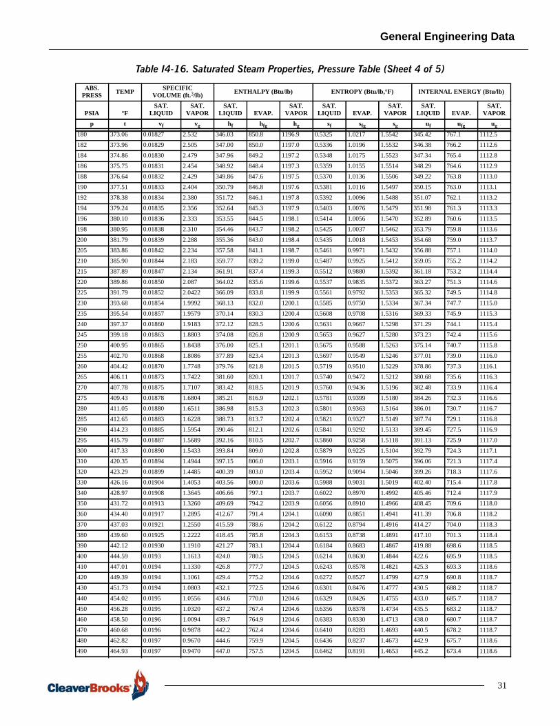
General Engineering Data
Table I4-16. Saturated Steam Properties, Pressure Table (Sheet 4 of 5)
180 373.06 0.01827 2.532 346.03 850.8 1196.9 0.5325 1.0217 1.5542 345.42 767.1 1112.5
182 373.96 0.01829 2.505 347.00 850.0 1197.0 0.5336 1.0196 1.5532 346.38 766.2 1112.6
184 374.86 0.01830 2.479 347.96 849.2 1197.2 0.5348 1.0175 1.5523 347.34 765.4 1112.8
186 375.75 0.01831 2.454 348.92 848.4 1197.3 0.5359 1.0155 1.5514 348.29 764.6 1112.9
188 376.64 0.01832 2.429 349.86 847.6 1197.5 0.5370 1.0136 1.5506 349.22 763.8 1113.0
190 377.51 0.01833 2.404 350.79 846.8 1197.6 0.5381 1.0116 1.5497 350.15 763.0 1113.1
192 378.38 0.01834 2.380 351.72 846.1 1197.8 0.5392 1.0096 1.5488 351.07 762.1 1113.2
194 379.24 0.01835 2.356 352.64 845.3 1197.9 0.5403 1.0076 1.5479 351.98 761.3 1113.3
196 380.10 0.01836 2.333 353.55 844.5 1198.1 0.5414 1.0056 1.5470 352.89 760.6 1113.5
198 380.95 0.01838 2.310 354.46 843.7 1198.2 0.5425 1.0037 1.5462 353.79 759.8 1113.6
200 381.79 0.01839 2.288 355.36 843.0 1198.4 0.5435 1.0018 1.5453 354.68 759.0 1113.7
205 383.86 0.01842 2.234 357.58 841.1 1198.7 0.5461 0.9971 1.5432 356.88 757.1 1114.0
210 385.90 0.01844 2.183 359.77 839.2 1199.0 0.5487 0.9925 1.5412 359.05 755.2 1114.2
215 387.89 0.01847 2.134 361.91 837.4 1199.3 0.5512 0.9880 1.5392 361.18 753.2 1114.4
220 389.86 0.01850 2.087 364.02 835.6 1199.6 0.5537 0.9835 1.5372 363.27 751.3 1114.6
225 391.79 0.01852 2.0422 366.09 833.8 1199.9 0.5561 0.9792 1.5353 365.32 749.5 1114.8
230 393.68 0.01854 1.9992 368.13 832.0 1200.1 0.5585 0.9750 1.5334 367.34 747.7 1115.0
235 395.54 0.01857 1.9579 370.14 830.3 1200.4 0.5608 0.9708 1.5316 369.33 745.9 1115.3
240 397.37 0.01860 1.9183 372.12 828.5 1200.6 0.5631 0.9667 1.5298 371.29 744.1 1115.4
245 399.18 0.01863 1.8803 374.08 826.8 1200.9 0.5653 0.9627 1.5280 373.23 742.4 1115.6
250 400.95 0.01865 1.8438 376.00 825.1 1201.1 0.5675 0.9588 1.5263 375.14 740.7 1115.8
255 402.70 0.01868 1.8086 377.89 823.4 1201.3 0.5697 0.9549 1.5246 377.01 739.0 1116.0
260 404.42 0.01870 1.7748 379.76 821.8 1201.5 0.5719 0.9510 1.5229 378.86 737.3 1116.1
265 406.11 0.01873 1.7422 381.60 820.1 1201.7 0.5740 0.9472 1.5212 380.68 735.6 1116.3
270 407.78 0.01875 1.7107 383.42 818.5 1201.9 0.5760 0.9436 1.5196 382.48 733.9 1116.4
275 409.43 0.01878 1.6804 385.21 816.9 1202.1 0.5781 0.9399 1.5180 384.26 732.3 1116.6
280 411.05 0.01880 1.6511 386.98 815.3 1202.3 0.5801 0.9363 1.5164 386.01 730.7 1116.7
285 412.65 0.01883 1.6228 388.73 813.7 1202.4 0.5821 0.9327 1.5149 387.74 729.1 1116.8
290 414.23 0.01885 1.5954 390.46 812.1 1202.6 0.5841 0.9292 1.5133 389.45 727.5 1116.9
295 415.79 0.01887 1.5689 392.16 810.5 1202.7 0.5860 0.9258 1.5118 391.13 725.9 1117.0
300 417.33 0.01890 1.5433 393.84 809.0 1202.8 0.5879 0.9225 1.5104 392.79 724.3 1117.1
310 420.35 0.01894 1.4944 397.15 806.0 1203.1 0.5916 0.9159 1.5075 396.06 721.3 1117.4
320 423.29 0.01899 1.4485 400.39 803.0 1203.4 0.5952 0.9094 1.5046 399.26 718.3 1117.6
330 426.16 0.01904 1.4053 403.56 800.0 1203.6 0.5988 0.9031 1.5019 402.40 715.4 1117.8
340 428.97 0.01908 1.3645 406.66 797.1 1203.7 0.6022 0.8970 1.4992 405.46 712.4 1117.9
350 431.72 0.01913 1.3260 409.69 794.2 1203.9 0.6056 0.8910 1.4966 408.45 709.6 1118.0
360 434.40 0.01917 1.2895 412.67 791.4 1204.1 0.6090 0.8851 1.4941 411.39 706.8 1118.2
370 437.03 0.01921 1.2550 415.59 788.6 1204.2 0.6122 0.8794 1.4916 414.27 704.0 1118.3
380 439.60 0.01925 1.2222 418.45 785.8 1204.3 0.6153 0.8738 1.4891 417.10 701.3 1118.4
390 442.12 0.01930 1.1910 421.27 783.1 1204.4 0.6184 0.8683 1.4867 419.88 698.6 1118.5
400 444.59 0.0193 1.1613 424.0 780.5 1204.5 0.6214 0.8630 1.4844 422.6 695.9 1118.5
410 447.01 0.0194 1.1330 426.8 777.7 1204.5 0.6243 0.8578 1.4821 425.3 693.3 1118.6
420 449.39 0.0194 1.1061 429.4 775.2 1204.6 0.6272 0.8527 1.4799 427.9 690.8 1118.7
430 451.73 0.0194 1.0803 432.1 772.5 1204.6 0.6301 0.8476 1.4777 430.5 688.2 1118.7
440 454.02 0.0195 1.0556 434.6 770.0 1204.6 0.6329 0.8426 1.4755 433.0 685.7 1118.7
450 456.28 0.0195 1.0320 437.2 767.4 1204.6 0.6356 0.8378 1.4734 435.5 683.2 1118.7
460 458.50 0.0196 1.0094 439.7 764.9 1204.6 0.6383 0.8330 1.4713 438.0 680.7 1118.7
470 460.68 0.0196 0.9878 442.2 762.4 1204.6 0.6410 0.8283 1.4693 440.5 678.2 1118.7
480 462.82 0.0197 0.9670 444.6 759.9 1204.5 0.6436 0.8237 1.4673 442.9 675.7 1118.6
490 464.93 0.0197 0.9470 447.0 757.5 1204.5 0.6462 0.8191 1.4653 445.2 673.4 1118.6
ABS. PRESS TEMP SPECIFIC
VOLUME (ft.3/lb) ENTHALPY (Btu/lb) ENTROPY (Btu/lb,°F) INTERNAL ENERGY (Btu/lb)
PSIA °FSAT.
LIQUIDSAT.
VAPORSAT.
LIQUID EVAP.SAT.
VAPORSAT.
LIQUID EVAP.SAT.
VAPORSAT.
LIQUID EVAP.SAT.
VAPORp t vf vg hf hfg hg sf sfg sg uf ufg ug
31

General Engineering Data
ABS. PRESS TEMP SPECIFIC
VOLUME (ft.3/in2) ENTHALPY (Btu/lb) ENTROPY (Btu/lb,°F) INTERNAL ENERGY (Btu/lb)
PSIA °FSAT.
LIQUID EVAP.
SAT.VA-POR
SAT.LIQUID EVAP.
SAT. VA-POR
SAT.LIQUID EVAP.
SAT.VA-POR
SAT.LIQUID
SAT.VA-POR
p t vf vfg vg hf hfg hg sf sfg sg uf ug500 467.01 0.0197 0.9081 0.9278 449.4 755.0 1204.4 0.6487 0.8147 1.4634 447.6 1118.6520 471.07 0.0198 0.8717 0.8915 454.1 750.1 1204.2 0.6536 0.8060 1.4596 452.2 1118.4540 475.01 0.0199 0.8379 0.8578 458.6 745.4 1204.0 0.6584 0.7976 1.4560 456.6 1118.3560 478.85 0.0200 0.8065 0.8265 463.0 740.8 1203.8 0.6631 0.7893 1.4524 460.9 1118.2580 482.58 0.0201 0.7772 0.7973 467.4 736.1 1203.5 0.6676 0.7813 1.4489 465.2 1118.0600 486.21 0.0201 0.7497 0.7698 471.6 731.6 1203.2 0.6720 0.7734 1.4454 469.4 1117.7620 489.75 0.0202 0.7238 0.7440 475.7 727.2 1202.9 0.6763 0.7658 1.4421 473.4 1117.5640 493.21 0.0203 0.6995 0.7198 479.8 722.7 1202.5 0.6805 0.7584 1.4389 477.4 1117.3660 496.58 0.0204 0.6767 0.6971 483.8 718.3 1202.1 0.6846 0.7512 1.4358 481.3 1117.0680 499.88 0.0204 0.6553 0.6757 487.7 714.0 1201.7 0.6886 0.7441 1.4327 485.1 1116.7700 503.10 0.0205 0.6349 0.6554 491.5 709.7 1201.2 0.6925 0.7371 1.4296 488.8 1116.3720 506.25 0.0206 0.6156 0.6362 495.3 705.4 1200.7 0.6963 0.7303 1.4266 492.5 1116.0740 509.34 0.0207 0.5973 0.6180 499.0 701.2 1200.2 0.7001 0.7237 1.4237 496.2 1115.6760 512.36 0.0207 0.5800 0.6007 502.6 697.1 1199.7 0.7037 0.7172 1.4209 499.7 1115.2780 515.33 0.0208 0.5635 0.5843 506.2 692.9 1199.1 0.7073 0.7108 1.4181 503.2 1114.8800 518.23 0.0209 0.5478 0.5687 509.7 688.9 1198.6 0.7108 0.7045 1.4153 506.6 1114.4820 521.08 0.0209 0.5329 0.5538 513.2 684.8 1198.0 0.7143 0.6983 1.4126 510.0 1114.0840 523.88 0.0210 0.5186 0.5396 516.6 680.8 1197.4 0.7177 0.6922 1.4099 513.3 1113.6860 526.63 0.0211 0.5049 0.5260 520.0 676.8 1196.8 0.7210 0.6862 1.4072 516.6 1113.1880 529.33 0.0212 0.4918 0.5130 523.3 672.8 1196.1 0.7243 0.6803 1.4046 519.9 1112.6900 531.98 0.0212 0.4794 0.5006 526.6 668.8 1195.4 0.7275 0.6744 1.4020 523.1 1112.1
Table I4-16. Saturated Steam Properties, Pressure Table (Sheet 5 of 5)
32
UNIT CONVERSIONSNote that pressures are typically given in gauge pressure. This is the differencebetween the absolute pressure in the boiler and the absolute pressure of thesurroundings. A gauge reads pressure differences (in most cases, the differencebetween the pressure of the substance and that of the atmosphere). Therefore,gauge pressure may be positive or negative (vacuum). Gauge pressures, in U.S.(English Engineering) units, are referred to as psig (pounds per square inch gauge,although the “g” is frequently omitted).
An absolute pressure is the pressure above zero pressure, which can only bepositive. Most thermodynamic tables are based on absolute pressure. In U.S. units,absolute pressure is referred to as psia (pounds per square inch absolute).
Absolute pressure is calculated by adding the absolute pressure of the surroundings(atmospheric pressure) to the gauge pressure. In general, for U.S. units (psig) toconvert gauge pressure to absolute pressure, add 14.696. Conversely, to convertabsolute pressure to gauge pressure, subtract 14.696.
The following information is included for your convenience.
• Temperature Conversion
• Conversions Factors 2
• pH Values
• Salinity Indicating Readings Conversion Table
• Useful Physical Constants
• Conversions Table
• Approximate Common Equivalents
• Conversions Accurate to Parts per Million

General Engineering Data
33

General Engineering Data
34
Table 17. Temperature Conversion

General Engineering Data
Table 18. Conversion Factors (Sheet 1 of 9)
35

General Engineering Data
36
Table I4-18. Conversions Factors (Sheet 2 of 9)

General Engineering Data
37
Table I4-18. Conversions Factors (Sheet 3 of 9)

General Engineering Data
38

General Engineering Data
39
Table I4-18. Conversions Factors (Sheet 4 of 9)

General Engineering Data
40
Table I4-18. Conversions Factors (Sheet 5 of 9)

General Engineering Data
41
Table I4-18. Conversions Factors (Sheet 6 of 9)

General Engineering Data
42
Table 18. Conversions Factors (Sheet 7 of 9)
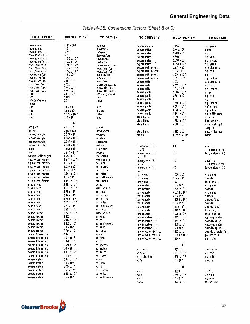
General Engineering Data
43
Table I4-18. Conversions Factors (Sheet 8 of 9)

General Engineering Data
4
Table I4-18. Conversions Factors (Sheet 9 of 9)
Table 19. pH Values
4
Table 20. Salinity Indicating Readings Conversion Tables
Table 21. Useful Physical Constants
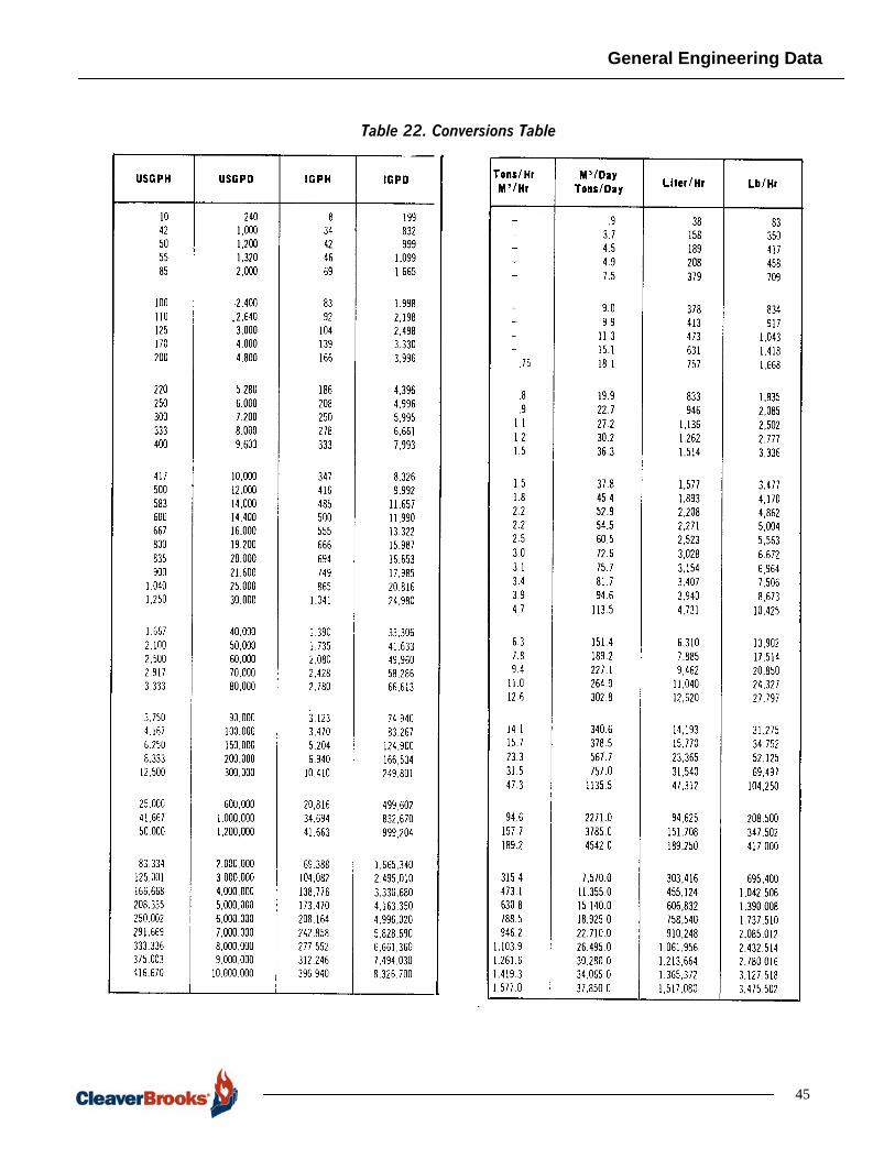
General Engineering Data
Table 22. Conversions Table
45

General Engineering Data
46
Table 23. Approximate Common Equivalents
Table 24. Conversions Accurate to Parts per Million

General Engineering Data
STANDARDS ASSOCIATIONS
American Gas Association (AGA)400 North Capitol St. NWWashington, DC 20001202-824-7250
www.aga.org
American National Standards Institute (ANSI)25 West 43rd Street, 4th FloorNew York, NY 10036212-642-4900
www.ansi.org
ANSI acts as the national coordinating institution through which interestedorganizations voluntarily cooperate in establishing, recognizing, and improvingstandards.
American Society of Heating Refrigerating and Air Conditioning Engineers(ASHRAE)1791 Tullie Circle, NEAtlanta, GA 30329404-636-8400
www.ashrae.org
American Society of Mechanical Engineers (ASME)Three Park AvenueNew York, NY 10016-5990800-843-2763
www.asme.org
The ASME develops test codes for boilers and pressure vessels and for powerapplications, and serves as a sponsor for ANSI in developing safety codes andstandards.
American Society for Nondestructive Testing1171 Arlingate LaneColumbus, Ohio 43228-0511614-274-6003800-222-2768
www.asnt.org
American Society for Testing and Materials (ASTM)100 Barr Harbor DriveWest Conshohocken, PA 19428-2959610-832-9500
www.astm.org
ASTM is the largest voluntary standards development system in the worldpublishing standards for materials, products, systems and services.
47
General Engineering Data
Canadian Standards Association (CSA)178 Rexdale Blvd.Etobicoke, Ontario, Canada M9W 1R3416-747-4000
www.csa-international.org
CSA, a nonprofit nongovernmental body, which promotes nationwide standards forproduct design, construction and performance for Canada. CSA is a recognizedtesting agency.
Canadian Gas Association (CGA)350 Sparks St., Suite 809Ottawa, Ontario K1R 7S8613-748-0057
www.cga.ca
CGA, a nonprofit association of manufacturers of gas utilities, provides certificationservice based on standards established by CSA.
FM Global1151 Boston-Providence TurnpikeNorwood, MA 02062781-762-4300
www.fmglobal.com
FM is an association of 4 mutual insurance companies dedicated to minimizing lossof insured property. Through its research arm, the Factory Mutual ResearchCorporation, it investigates means of preventing and minimizing fire and otherlosses. FM laboratories provide product testing and approval.
XL Global Asset Protection Services (XL GAPS)
xlgaps.com
Formerly IRI/GEGAP
National Board of Boiler and Pressure Vessel Inspectors1055 Crupper AvenueColumbus, OH 43229-1183614-888-8320
The National Board is an organization comprised of Chief Inspectors of states andcities of the US and provinces of Canada organized for the purpose of promotinggreater safety in the construction, installation, inspection and repair of boilers andpressure vessels.
National Electric Code (NEC)1 Batterymarch Park Quincy, MA 02269-9101
The National Electric Code is a standard established for safe wiring procedures inthe interest of personal safety and fire protection. The code is adopted andcopyrighted by the NFPA (see National Fire Protection Association).
48
General Engineering Data
National Fire Protection Association (NFPA)1 Batterymarch Park Quincy, MA 02169-7471617-770-3000
www.nfpa.org
NFPA develops and promotes standards for the purpose of advancing the scienceand improving the methods of fire protection and prevention.
Underwriters Laboratories (UL and cUL)333 Pfingsten RoadNorthbrook, IL 60062
www.ul.com
UL is a nonprofit organization which operates laboratories for testing for publicsafety. They provide listings, classification, recognition and certification. UL is arecognized testing agency for the U.S. and Canada.
Underwriters Laboratories of Canada (ULC)7 Underwriters RoadToronto, Ontario M1R 3A9
www.ul.com/canada
ULC is an agency sponsored by the Canadian Underwriters Association that testsand certifies products and materials against ULC established standards. It has norelationship to UL of the U.S.
United States Department of Energy (DOE)100 Independence Avenue, SWWashington, DC 20585
energy.gov
United States Environmental Protection Agency (EPA)Ariel Rios Building1200 Pennsylvania Ave. NWWashington, DC202-272-0167
www.epa.gov
49

General Engineering Data
50
Related Documents


![1001 Solved Problems in Engineering Mathematics [Day 1 System of Numbers & Conversion]](https://static.cupdf.com/doc/110x72/577c77801a28abe0548c5b9b/1001-solved-problems-in-engineering-mathematics-day-1-system-of-numbers-.jpg)