TREBLE R FABRICATIONS UNIT 42 – CROSSGATE ROAD – PARK FARM INDUSTRIAL ESTATE – REDDITCH – WORCS – B987SN ……………………………………………………………………………………………………. tel 01527 503 303 – fax 01527 503 325 – web www.treblerfabrications.co.uk ACTUATOR BEVEL GEAR BOX SPURBOX SQUARE CAP HANDWHEEL PROTECTION TUBE FOOTPLATE BRK’T GUIDE BRACKET THRUST HOUSING MUFF COUPLING SURFACE BOX PILLAR GENERAL PENSTOCK OPERATING

Welcome message from author
This document is posted to help you gain knowledge. Please leave a comment to let me know what you think about it! Share it to your friends and learn new things together.
Transcript
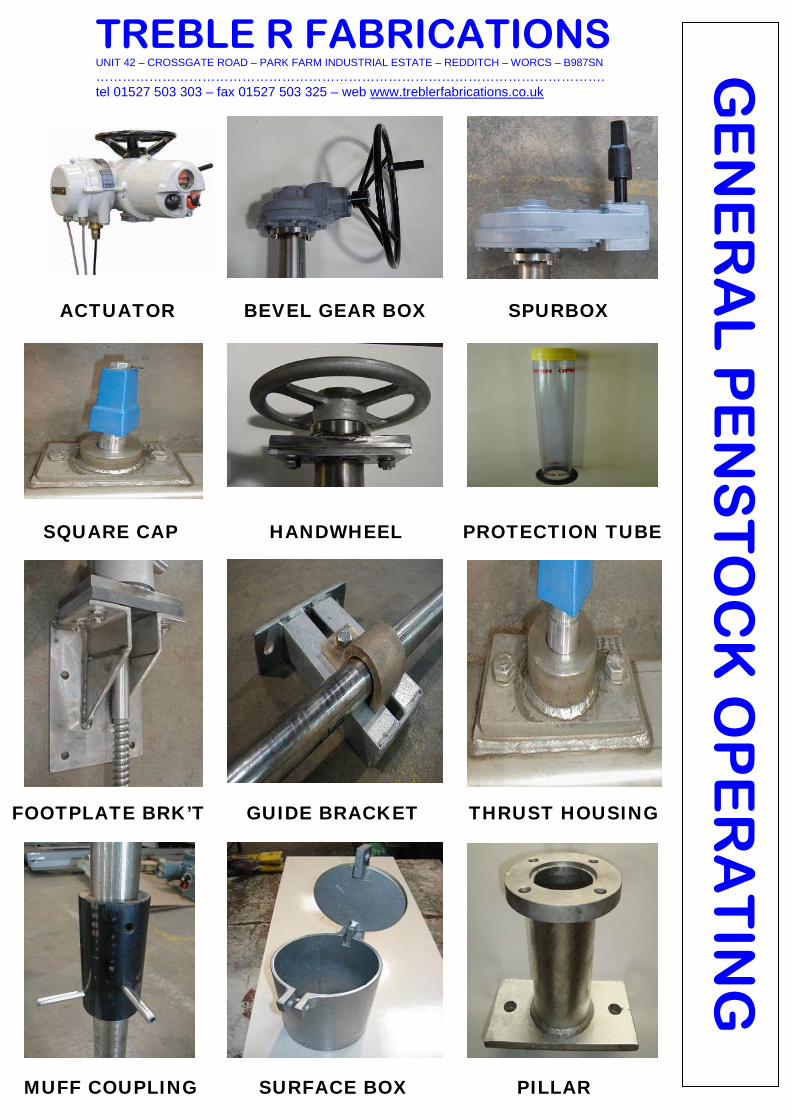
TREBLE R FABRICATIONS UNIT 42 – CROSSGATE ROAD – PARK FARM INDUSTRIAL ESTATE – REDDITCH – WORCS – B987SN ……………………………………………………………………………………………………. tel 01527 503 303 – fax 01527 503 325 – web www.treblerfabrications.co.uk
ACTUATOR BEVEL GEAR BOX SPURBOX
SQUARE CAP HANDWHEEL PROTECTION TUBE
FOOTPLATE BRK’T GUIDE BRACKET THRUST HOUSING
MUFF COUPLING SURFACE BOX PILLAR
GE
NE
RA
L P
EN
ST
OC
K O
PE
RA
TIN
G

Operating Gear All penstock gates require opening and closing by a connecting spindle and operating device. This can be either mounted direct to frame or remotely at coping level. The operating device can be either of the following : . Square Cap . Handwheel . Electric Actuator . Bevel or Spur Gearbox . Hydraulic or Pneumatic Cylinder

NON-RISING STEM APPLICATIONS
Operation for Non-Rising stem applications. This series provides an extensive range of operating equipment for Non-Rising Stem applications for use with Penstocks and a wide selection of valves. The operating equipment illustrates typical applications and can be configured to satisfy specific requirements.

Operating Equipment: Non-Rising Stem Applications
Option Description A Electric Actuator on a floor pillar B Bevel Gearbox on a floor pillar C Handwheel assembly on a floor pillar D Bevel gearbox on a floor pillar with universal couplings E Adapter square for tee key operation in surface box F Handwheel assembley on a coping bracket
Item Description 1 Penstock Unit 2 Non-rising Stem 3 Thrust Assembly 4 Adjustable Guide Bracket 5 Muff Coupling 6 Extension Stem 7 Pillar 8 Coping Bracket (Footplate) 9 Handwheel Assembly 10 Electric Actuator 11 Bevel Gearbox 12 Adapter Square 13 Universal Coupling

RISING STEM APPLICATIONS
Operation for Rising Stem Applications. This series provides an extensive range of operating equipment for Rising Stem Applications for use with Penstocks and a selection of Valves. The operating equipment illustrates typical applications and can be configured to satisfy specific requirements.

OPERATING EQUIPMENT: RISING STEM APPLICATIONS
Option Description A Electric Actuator on with clear polycarbonate or steel
protection tube on a floor pillar B Bevel Gearbox with clear polycarbonate or steel protection tube on a floor pillar C Handwheel and thrust assembly with clear polycarbonate protection tube on a floor pillar D Hydraulic or pneumatic linear actuator on a floor pillar E Handwheel and thrust assembly with clear
polycarbonate protection tube on a floor pillar
Item Description 1 Penstock Unit 2 Lower rising Stem 3 Adjustable Guide Bracket 4 Muff Coupling 5 Upper rising Stem 6 Pillar 7 Short Floor Stool 8 Coping Bracket (Footplate) 9 Manual Thrust Assembly 10 Electric Actuator 11 Bevel Gearbox 12 Linear Actuator 13 Polycarbonate Protection Tube 14 Steel Protection tube

Penstocks/Sluice Gates TECHNICAL DETAILS AND SPECIFICATIONS Civil Work Loading The thrust generated during opening or closing of the penstock can be transferred to the supporting structure in two ways.
1. Locally in the penstock 2. Remotely at the floor, coping or corbel level.
Thrust tubes can be introduced between the operator and the penstock frame to enable the operating thrust to be transferred to the penstock for remote operation. For lower operating duties and smaller sized penstocks wall brackets can be supplied to transfer the thrust to the coping. However, for larger and higher duty penstocks we recommend that a corbel is constructed. Vertical Reactions on Civil Work Installations where operating thrust has to be taken at an independent floor pedestal. The concrete corbel or similar structure to which it is attached, must be designed to withstand the maximum forces transmitted to it by the operating gear. An approximate value for the vertical reaction may be derived from:- Vr = [A (300H + K)] F x 9.81 Where Vr = Vertical reaction (N) A = Area of aperture (m2) H = Head from invert of door/gate (m) K = Penstock/sluice gate factor F = 1 for manual operation or 1.5 for power/gearbox operation. Penstock/Sluice Gate Series K Factor Treble R Fabrications Parallel 125 Treble R Fabrications Adjustable 150 Thrust calculations for loadings on civil structures can generally be supplied on request. Note: When an electric actuator is fitted the vertical reaction is based on the rated torque of the actuator.

Penstocks/Sluice Gates TECHNICAL DETAIL AND SPECIFICATION Operating Thrust The method of calculating the vertical reactions on civil work demonstrated on the previous page is an approximation and satisfactory for the purpose intended. However, calculation of operating torque and thrust must be more precise for determination of actuator or gearbox sizes. The maximum thrust is required from the operator during off-seating and raising the door; this is due to the frictional effect of the adjusters and lifting the mass of the door and stem. In closing, or normally the downward movement of the door, the mass of the door and stem act in the direction of the motion and reduce the force required when compared to the unseating condition. The force required to activate the gate is, in part empirically determined. The mass of the door and stem, the head of water on the door at the centreline of the opening, and the friction of the door against the seats and wedges are required to calculate the force to open the gate. These factors can be presented as follows:- F = 9.81 [f.A.H. + (1.5 P1 + P)]…………..(Equation 1) F1 =9.81 [f.A.H. + (P1 + P2)] ……………(Equation 2) Where: F = Maximum force (thrust) required to open door, in kilo newtons (KN) F1 = Maximum force (thrust) required to close door, In kilo newtons (KN) f = Friction factor between the door and seats, 0.25 (resilient seals) A = Area of aperture, in metres (M) H = Head of water at door centreline, in metres (M) P1= Mass of door, in tonnes (t) P2 = Mass of stem, in tonnes (t) The friction factor (f) between the door on the seats may be taken as 0.25 for seating and off seating penstocks. The force to overcome the frictional effect of the wedges is accounted for by empirically assigning a factor of 1.5 to the mass of the door. The mass of the door can be provided by the penstock manufacturer; however, as stem mass must be estimated in the initial calculation to determine the thrust. Re- calculation will be necessary for an accurate thrust value when the stem diameter has been determined.


Penstocks/Sluice Gates Determination of Stem Diameter Several factors govern the size of electric actuator or gearbox: that is, the thrust, torque, stem diameter etc. When the operating thrust has been determined the maximum (off-seating) value should be used in the stem diameter calculation. The basis of the calculation method is the Euler Column Formula for critical buckling load: - P = C x Pye x Pye x E x A x (r/l)2…………………Equation 3 Where P = Axial thrust on stem in newtons (N) C = End restraint conditions E = Modulus of elasticity in N/mm2
A = Area of stem in mm2
R = radius of gyration in mm L = length of span between supports in mm Clearly, the, euler Column Formula, equation 3 in the format presented is unsuitable for stem diameter calculation. However, with transposition and manipulation equation 4 can be derived as follows: - D = [64 x P x L x L [C x Pye x Pye x Pye x E ]
] 0.25 ………………….Equation 4
Where D = Stem diameter in mm P = Axial thrust on stem in Newton (N) C = End restrain conditions, as value of 2 is recommended l = unsupported length in mm F = Factor of safety (minimum of 5 recommended) E = Modulus of elasticity in N/mm2
Equation 4 will provide a theoretical stem diameter. However, for practical purposes the next largest bar size available should be used.
The stem slenderness ration must be less than 200 (.SR < 200), this can be established using equation 5. Unsupported length = 1 or Slenderness ration (SR) = radius of gyration r D
41
…………………………………………………………..Equation 5 The radius gyration 4 is valid for circular sections
D

TECHNICAL DETAILS AND SPECIFICATIONS
The unsupported length is the distance between fixed ends of the stem or support bracket spacings ; sufficient spacing should be allowed for the door travel on rising stem applications. Determination of Torque Determination of the operating torque depends on several factors. Some have already been calculated: that is the operating thrust and the stem diameter. To complete the torque calculation the thread lead and profile is required to determine the thread efficiency. Tan oc Thread efficiency e = Tan ( oc + kO……………..Equation 6 Where Lead of thread Tan oc = Pye x effective diameter……………Equation 7 Tan –1 O = 0.15 for lubricated stems (rising type) or 0.20 for unlubricated stems (non-rising type) 1 K = cos B where……………………………………….. B = half the included thread flank angle, this is a constant applied to tan –1 o So PL T = 2 Pye e …………………………………………………..Equation 8 Where T = Torque at stem in Nm P = Total thrust in N L = Lead of thread in metres (m) e = Efficiency of thread. Calculation of the maximum thrust (eq. 1), stem diameter (eq. 4) and the operating torque (eq. 8) enables the size of the actuator or gearbox to be determined. The ‘rated’ output torque from the operator should be converted to thrust by transposition of equation 8, and the stem diameter confirmed by completing a calculation using equation 4 again. The ‘rated’ torque can be used for civil work loading calculation with the appropriate factors of safety with increased accuracy over the method demonstrated previously.
Related Documents