Troubleshooting Manual Gen II Automated Transmissions TRTS0062 EN-US May 2013 FO-6406A-ASW FO-6406A-ASX FO-8406A-ASW FO-8406A-ASX RT-14910B-AS2 RTLO-14918A-AS2 RTLO-16918A-AS2 RTLO-18918A-AS2 RTLO-20918A-AS2 RTLO-22918A-AS2 RTO-10710B-AS2 RTO-10910B-AS2 RTO-10910B-DM2 RTO-12710B-AS2 RTO-12910B-AS2 RTO-12910B-DM2 RTO-14710B-AS2 RTO-14710C-AS2 RTO-14910B-AS2 RTO-14910B-DM2 RTO-14910C-AS2 RTO-16710C-AS2 RTO-16910B-AS2 RTO-16910B-DM2 RTO-16910C-AS2 RTO-18910B-AS2

Welcome message from author
This document is posted to help you gain knowledge. Please leave a comment to let me know what you think about it! Share it to your friends and learn new things together.
Transcript
Troubleshooting Manual
Gen II Automated TransmissionsTRTS0062 EN-USMay 2013
FO-6406A-ASW
FO-6406A-ASX
FO-8406A-ASW
FO-8406A-ASX
RT-14910B-AS2
RTLO-14918A-AS2
RTLO-16918A-AS2
RTLO-18918A-AS2
RTLO-20918A-AS2
RTLO-22918A-AS2
RTO-10710B-AS2
RTO-10910B-AS2
RTO-10910B-DM2
RTO-12710B-AS2
RTO-12910B-AS2
RTO-12910B-DM2
RTO-14710B-AS2
RTO-14710C-AS2
RTO-14910B-AS2
RTO-14910B-DM2
RTO-14910C-AS2
RTO-16710C-AS2
RTO-16910B-AS2
RTO-16910B-DM2
RTO-16910C-AS2
RTO-18910B-AS2

20
Table of ContentsTRTS0062
Table of Contents
General InformationWarnings and Cautions . . . . . . . . . . . . . . . . . . . . . . . . .1Suggested Tools . . . . . . . . . . . . . . . . . . . . . . . . . . . . . .2
Air Gauges . . . . . . . . . . . . . . . . . . . . . . . . . . . . . . . .2Volt/Ohm Meter . . . . . . . . . . . . . . . . . . . . . . . . . . . .2PC-based Service Tool “ServiceRanger” . . . . . . . . .2Shift Lever Tester . . . . . . . . . . . . . . . . . . . . . . . . . .2Eaton Test Adapter Kit . . . . . . . . . . . . . . . . . . . . . . .26-Pin Deutsch Diagnostic Adapter . . . . . . . . . . . . . .2
Transmission Models Included . . . . . . . . . . . . . . . . . . .3Diagnostic Procedure . . . . . . . . . . . . . . . . . . . . . . . . . .4Fault Code Retrieval/Clearing . . . . . . . . . . . . . . . . . . . .5
Retrieving Fault Codes . . . . . . . . . . . . . . . . . . . . . .5Clearing Fault Codes . . . . . . . . . . . . . . . . . . . . . . . .6
Driving Techniques . . . . . . . . . . . . . . . . . . . . . . . . . . . .7Fault Code Isolation Procedure Index . . . . . . . . . . . . .12Symptom-Driven Diagnostics Index . . . . . . . . . . . . . .14
Electrical Pretest ProcedureElectrical System Pretest . . . . . . . . . . . . . . . . . . . . . .15Power-Up Sequence Pretest . . . . . . . . . . . . . . . . . . . .18Air Pretest . . . . . . . . . . . . . . . . . . . . . . . . . . . . . . . . . .24
Fault Isolation ProcedureFault Code 11: Shift Controller . . . . . . . . . . . . . . . . . .28Fault Code 12: Transmission Controller . . . . . . . . . . .32Fault Code 14: Invalid Lever Position . . . . . . . . . . . . .36Fault Code 16: Eaton Proprietary Link (EPL) . . . . . . . .42Fault Code 17: Start Enable Relay Coil . . . . . . . . . . . .48Fault Code 26: Clutch Slip . . . . . . . . . . . . . . . . . . . . . .54Fault Code 27: Clutch Disengagement . . . . . . . . . . . . .58Fault Code 28: Clutch System Fault . . . . . . . . . . . . . . .62Fault Code 31: Momentary Engine Ignition Interrupt Relay (MEIIR) . . . . . . . . . . . . . . . . . . . . . . . .68Fault Code 32: Switched System Voltage . . . . . . . . . .74Fault Code 33: Battery Voltage Supply . . . . . . . . . . . .78Fault Code 35: J1939 Data Link . . . . . . . . . . . . . . . . .82Fault Code 41: Range Failed to Engage . . . . . . . . . . . .88Fault Code 42: Splitter Failed to Engage . . . . . . . . . . .92Fault Code 43: Range Valve . . . . . . . . . . . . . . . . . . . . .96Fault Code 44: Inertia Brake Solenoid Coil . . . . . . . .102Fault Code 46: Splitter Valve . . . . . . . . . . . . . . . . . . .108Fault Code 51: Rail Select Sensor . . . . . . . . . . . . . . .114
Fault Code 52: Gear Select Sensor . . . . . . . . . . . . . .120Fault Code 56: Input Shaft Speed Sensor . . . . . . . . .124Fault Code 57: Main Shaft Speed Sensor . . . . . . . . .130Fault Code 58: Output Shaft Speed Sensor . . . . . . . .134Fault Code 61: Rail Select Motor . . . . . . . . . . . . . . . .140Fault Code 63: Gear Select Motor . . . . . . . . . . . . . . .146Fault Code 65: Logic Power . . . . . . . . . . . . . . . . . . .152Fault Code 71: Stuck Engaged . . . . . . . . . . . . . . . . . .158Fault Code 72: Failed to Select Rail . . . . . . . . . . . . . .162Fault Code 73: Failed to Engage Gear . . . . . . . . . . . .166Fault Code 74: Failed to Synchronize . . . . . . . . . . . .170Fault Code 81: Gear Engagement Detected . . . . . . . .174Fault Code 83: Missing Lever . . . . . . . . . . . . . . . . . .178Fault Code 91: Power Connection . . . . . . . . . . . . . . .182Fault Code 92: Weak System Battery Voltage . . . . . .186Fault Code 93: Loss of J1939 Communication from the Engine . . . . . . . . . . . . . . . . . . . . . . . . . . . .190
Symptom Isolation ProcedureElectrical System . . . . . . . . . . . . . . . . . . . . . . . . . . . .194Front Box Control . . . . . . . . . . . . . . . . . . . . . . . . . . .204Gear Display Power Supply . . . . . . . . . . . . . . . . . . . .208Start Enable Relay Contact . . . . . . . . . . . . . . . . . . . .214AutoShift Will Not Engage a Gear . . . . . . . . . . . . . . .220UltraShift DM Will Not Engage a Gear . . . . . . . . . . . .228UltraShift ASW Will Not Engage a Gear . . . . . . . . . . .236J1587 Data Link . . . . . . . . . . . . . . . . . . . . . . . . . . . .242Range System Test . . . . . . . . . . . . . . . . . . . . . . . . . .248Splitter System . . . . . . . . . . . . . . . . . . . . . . . . . . . . .252Up/Down Button Test . . . . . . . . . . . . . . . . . . . . . . . .256UltraShift DM Shift Complaint . . . . . . . . . . . . . . . . . .260UltraShift ASW Shift Complaint . . . . . . . . . . . . . . . . .266UltraShift ASW Clutch Engagement . . . . . . . . . . . . .274Transmission Air Leak . . . . . . . . . . . . . . . . . . . . . . .278Shift Lever Back Light . . . . . . . . . . . . . . . . . . . . . . . .284
i© 2013 Eaton. All rights reserved13.07.17

ii
Table of Contents TRTS0062
AppendixConnector Pin Descriptions . . . . . . . . . . . . . . . . . . .288
Transmission Controller 18-Way (Vehicle Interface Connector) . . . . . . . . . . . . . . .288Transmission Controller 30-Way Connector . . . .289Shift Controller 30-Way Connector . . . . . . . . . . .291
Wiring Diagrams . . . . . . . . . . . . . . . . . . . . . . . . . . . .2946-Speed and 7-Speed AutoShift . . . . . . . . . . . . .2946-Speed UltraShift ASW . . . . . . . . . . . . . . . . . . .29610-Speed AutoShift . . . . . . . . . . . . . . . . . . . . . . .29810-Speed UltraShift DM . . . . . . . . . . . . . . . . . . .30018-Speed AutoShift . . . . . . . . . . . . . . . . . . . . . . .302Eaton Shift Lever . . . . . . . . . . . . . . . . . . . . . . . . .304OEM Shift Lever . . . . . . . . . . . . . . . . . . . . . . . . .304
Proper Clutch Operation . . . . . . . . . . . . . . . . . . . . . .306Check For Proper Clutch Operation . . . . . . . . . . .306Confirm Proper Clutch Adjustment and Clutch Brake Contact . . . . . . . . . . . . . . . . . .306
Adapter Test Kit J43318 . . . . . . . . . . . . . . . . . . . . . .308Gray Adapters . . . . . . . . . . . . . . . . . . . . . . . . . . .308Purple Adapters . . . . . . . . . . . . . . . . . . . . . . . . . .308Adapter Pins . . . . . . . . . . . . . . . . . . . . . . . . . . . .308
Troubleshooting Worksheet . . . . . . . . . . . . . . . . . . .309
© 2013 Eaton. All rights reserved 2013.07.17

2013.07.17 © 2013 Eaton. All rights reserved 1
TRTS0062 General Information | Warnings and Cautions
Warnings and CautionsWarning: Follow the specified procedures in the indicated order to avoid personal injury
Caution: Follow the specified procedures in the indicated order to avoid equipment malfunction or damage
Note: Additional relevant information not covered in the service procedure.
Before starting a vehicle:
• Sit in the driver's seat
• Place Shift Lever in neutral
• Set the parking brake
Before working on a vehicle or leaving the cab with engine running:
• Place Shift Lever in neutral
• Set the parking brake
• Block the wheels
When parking the vehicle or leaving the cab:
• Place Shift Lever in neutral
• Set the parking brake
Caution: Do not release the parking brake or attempt to select a gear until the air pressure is at the correct level.
To avoid damage to the transmission during towing:
1. Place Shift Lever in neutral
2. Lift the drive wheels off of the ground or discon-nect the drivelink
Do not operate vehicle if Alternator light is lit or if gauges indicate low voltage.
!
!
!

2 © 2013 Eaton. All rights reserved 2013.07.17
Suggested Tools | General Information TRTS0062
Suggested Tools
Air Gauges• 2 (0-100) PSI Air Gauges
Volt/Ohm Meter • SPX / Kent-Moore 1 (800) 328-6657
• P/N 5505027
PC-based Service Tool “ServiceRanger”• Contact your OEM
Shift Lever Tester• Eaton Service Parts 1 (800) 826-4357
• P/N 691795
Eaton Test Adapter Kit• SPX / Kent-Moore 1 (800) 328-6657
• P/N J-43318
6-Pin Deutsch Diagnostic Adapter • SPX / Kent-Moore 1 (800) 328-6657
• P/N J-38500-60A
For more information call 1-800-826-HELP (826-4357)

2013.07.17 © 2013 Eaton. All rights reserved 3
TRTS0062 General Information | Transmission Models Included
Transmission Models Included
6-Speed 6-Speed ASW
7-Speed 18-Speed
10-Speed 10-Speed DM
4 © 2013 Eaton. All rights reserved 2013.07.17
Diagnostic Procedure | General Information TRTS0062
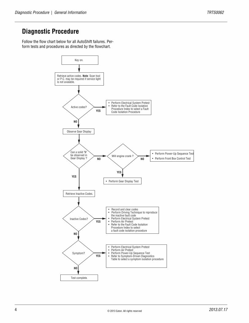
Diagnostic ProcedureFollow the flow chart below for all AutoShift failures. Per-form tests and procedures as directed by the flowchart.
• Perform Gear Display Test
Key on.
Can a solid "N"be observed inGear Display ? NO
Retrieve active codes. Note: Scan tool or P.C. may be required if service light is not avialable.
Active codes?
NO
YES
YES
• Perform Electrical System Pretest • Refer to the Fault Code Isolation Procedure Index to select a Fault Code Isolation Procedure
Observe Gear Display
Retrieve Inactive Codes.
Inactive Codes?
NO
YES
• Record and clear codes • Perform Driving Technique to reproduce the inactive fault code • Perform Electrical System Pretest • Perform Air Pretest • Refer to the Fault Code Isolation
Procedure Index to select a fault code isolation procedure
Symptom?YES
• Perform Electrical System Pretest• Perform Air Pretest• Perform Power-Up Sequence Test• Refer to Symptom-Driven Diagnostics
Table to select a symptom isolation procedure
Test complete.
NO
Will engine crank ?NO
YES
• Perform Front Box Control Test
• Perform Power-Up Sequence Test

TRTS0062 General Information | Fault Code Retrieval/Clearing
Fault Code Retrieval/Clearing
Retrieving Fault CodesRetrieve fault codes by enabling self-diagnostic mode.
Note: Use a PC-based Service Tool, such as the Ser-viceRanger to retrieve fault codes.
1. Place the Shift Lever in neutral.
2. Set the parking brake.
3. Turn the key on but do not start the engine. If the engine is running, you may still retrieve codes; however, do not engage the Starter if the engine stalls.
4. To Retrieve Active Codes: Turn the key off and on 2 times within 5 seconds ending with the key on. After 5 seconds, the Service light begins flashing 2-digit fault codes. If no faults are Active, the Ser-vice light will flash Code 25 (no codes).
5. To Retrieve Inactive Codes: Start with the key on. Turn key off and on 4 times within 5 seconds end-ing with the key on. After 5 seconds, the Service light begins flashing 2-digit fault codes. If no faults are Active, the Service light will flash Code 25 (no codes).
6. Observe the sequence of flashes on the Indicator light and record the codes. A 1 to 2 second pause separates each stored code, and the sequence automatically repeats after all codes have been flashed.
2 times
off on
4 times
off on
SERVICE
1 Flash
Shortpause
(1/2 sec)
Shortpause
(1/2 sec)
Long Pause(3-4 sec)
3 Flashes
2 Flashes
Code 13
Code 21
SERVICE
SERVICE
SERVICE
SERVICE
SERVICE
1 Flash SERVICE
2013.07.17 © 2013 Eaton. All rights reserved 5

6
Fault Code Retrieval/Clearing | General Information TRTS0062
Clearing Fault CodesThe following procedure clears all Inactive fault codes from the Transmission Controller memory. Active fault codes will be automatically cleared when the fault has been corrected.
Note: You may use a PC-based Service Tool, such as Ser-viceRanger, to clear fault codes.
1. Place the Shift Lever in neutral.
2. Set the parking brake.
3. Turn the key on, but do not start the engine.
4. Start with the key on. Turn the key off and on 6 times within 5 seconds ending with the key on.
Note: If the codes have been successfully cleared, the Service light will come on and stay on for 5 seconds.
5. Turn key off and allow the system to power down.
6 times
off on
© 2013 Eaton. All rights reserved 2013.07.17

TRTS0062 General Information | Driving Techniques
Driving Techniques
Fault Codes PID SID FMI Description Type of Code Driving Technique
11 254 12 Shift Controller Component
Key on. If the fault is present, the system should automatically detect the problem and set the code. If the fault is not present at key on, operate the ve-hicle and attempt to duplicate the driving condi-tions that triggered the fault code. Possible triggers include heat and vibration.
12 233 12 Transmission Controller Component
Key on. If the fault is present, the system should automatically detect the problem and set the code. If the fault is not present at key on, operate the ve-hicle and attempt to duplicate the driving condi-tions that triggered the fault code. Possible triggers include heat and vibration.
14 18 2, 4, 5 Invalid lever Po-sition Test Component
Key on. If the fault is present, the system should automatically detect the problem and set the code. If the fault is not present at key on, operate the ve-hicle and attempt to duplicate the driving condi-tions that triggered the fault code. Possible triggers include heat and vibration.
16 248 2 Eaton Propri-etary Link (EPL) Component
Key on. If the fault is present, the system should automatically detect the problem and set the code. If the fault is not present at key on, operate the ve-hicle and attempt to duplicate the driving condi-tions that triggered the fault code. Possible triggers include heat and vibration.
17 237 3, 4 Start Enable Re-lay Coil Component
Key on. If the fault is present, the system should automatically detect the problem and set the code. If the fault is not present at key on, operate the ve-hicle and attempt to duplicate the driving condi-tions that triggered the fault code. Possible triggers include heat and vibration.
25 NO CODES
26 55 10 Clutch Slip Component
Operate the vehicle under load in highest gear possible with engine speed above 1500 RPM. At a steady speed, quickly and fully press the throttle. The failure is detected when clutch slip occurs.
2013.07.17 © 2013 Eaton. All rights reserved 7

8
Driving Techniques | General Information TRTS0062
27 55 7 Clutch Disen-gagement Component
Operate the vehicle. If the fault is present, the sys-tem should automatically detect the problem and set the code. If the fault is not present, operate the vehicle and attempt to duplicate the driving condi-tions that triggered the fault code. Possible trig-gers include heat, vibration and aggressive stops.
28 52 3,4,5,7 Clutch System Fault Component
Key on. If the fault is present, the system should automatically detect the problem and set the code. If the fault is not present at key on, operate the ve-hicle and attempt to duplicate the driving condi-tions that triggered the fault code. Possible triggers include low clutch fluid level, heat and vi-bration.
31 218 3,4Momentary Igni-tion Interrupt Re-lay
Component
Key on. If the fault is present, the system should automatically detect the problem and set the code. This fault is only detected during system pow-er-up. If the fault is not present at power up, oper-ate the vehicle and attempt to duplicate the driving conditions that triggered the fault code. Possible triggers include heat, vibration.
32 62 4 Switched Voltage Supply Component
Key on. If the fault is present, the system should automatically detect the problem and set the code. If the fault is not present at key on, operate the ve-hicle and attempt to duplicate the driving condi-tions that triggered the fault code. Possible triggers include heat, vibration.
33 168 4 Battery Voltage Supply Component
Key on. If the fault is present, the system should automatically detect the problem and set the code. If the fault is not present at key on, operate the ve-hicle and attempt to duplicate the driving condi-tions that triggered the fault code. Possible triggers include heat, vibration.
35 231 2 J1939 Data Link System
Key on. If the fault is present, the system should automatically detect the problem and set the code. If the fault is not present at key on, operate the ve-hicle and attempt to duplicate the driving condi-tions that triggered the fault code. Possible triggers include heat, vibration, and varying levels of throttle demand. It may take up to 75 seconds to set this fault.
Fault Codes PID SID FMI Description Type of Code Driving Technique
© 2013 Eaton. All rights reserved 2013.07.17

TRTS0062 General Information | Driving Techniques
41 56 7 Range Failed to Engage System
Operate vehicle and perform several range up shifts and down shifts. The failure is detected after 5 consecutive attempts to complete the same type of range shift. Several shifts (10 or more) may be necessary before the controller confirms the fail-ure.
42 61 7 Splitter failed to Engage System
Operate vehicle and perform several range up shifts and down shifts. The failure is detected after 5 consecutive attempts to complete the same type of range shift. Several shifts (10 or more) may be necessary before the controller confirms the fail-ure.
43 35, 36 3, 4, 5 Range Valve Component
Key on. If the fault is present, the system should automatically detect the problem and set the code. If the fault is not present at key on, operate the ve-hicle and attempt to duplicate the driving condi-tions that triggered the fault code. Possible triggers include heat, vibration.
44 53 3, 4, 5 Inertia Brake So-lenoid Coil Component
Key on. If the fault is present, the system should automatically detect the problem and set the code. If the fault is not present at key on, operate the ve-hicle and attempt to duplicate the driving condi-tions that triggered the fault code. Possible triggers include heat, vibration.
46 37, 38 3, 4, 5 Splitter Valve Component
Key on. If the fault is present, the system should automatically detect the problem and set the code. If the fault is not present at key on, operate the ve-hicle and attempt to duplicate the driving condi-tions that triggered the fault code. Possible triggers include heat, vibration.
51 60 2, 3, 4, 10
Rail Select Sen-sor Component
Key on. If the fault is present, the system should automatically detect the problem and set the code. If the fault is not present at key on, operate the ve-hicle and attempt to duplicate the driving condi-tions that triggered the fault code. Possible triggers include heat, vibration.
52 59 2, 3, 4 Gear Select Sen-sor Component
Key on. If the fault is present, the system should automatically detect the problem and set the code. If the fault is not present at key on, operate the ve-hicle and attempt to duplicate the driving condi-tions that triggered the fault code. Possible triggers include heat, vibration.
Fault Codes PID SID FMI Description Type of Code Driving Technique
2013.07.17 © 2013 Eaton. All rights reserved 9

10
Driving Techniques | General Information TRTS0062
56 161 2, 5 Input Shaft Speed Sensor Component
Select a forward gear and drive at a steady speed no slower than 10 MPH. It may be necessary to operate the vehicle for a prolonged period of time if the cause of the failure is related to heat and vi-bration.
57 160 2 Main Shaft Speed Sensor Component
Select a forward gear and drive at a steady speed no slower than 10 MPH. It may be necessary to operate the vehicle for a prolonged period of time if the cause of the failure is related to heat and vi-bration.
58 191 2 Output Shaft Speed Sensor Component
Select a forward gear and drive at a steady speed no slower than 10 MPH. It may be necessary to operate the vehicle for a prolonged period of time if the cause of the failure is related to heat and vi-bration.
61 39 5, 6 Rail Select Motor Component
Key on. If the fault is present, the system should automatically detect the problem and set the code. If the fault is not present at key on, operate the ve-hicle and attempt to duplicate the driving condi-tions that triggered the fault code. Possible triggers include heat, vibration.
63 40 5, 6 Gear Select Mo-tor Component
Key on. If the fault is present, the system should automatically detect the problem and set the code. If the fault is not present at key on, operate the ve-hicle and attempt to duplicate the driving condi-tions that triggered the fault code. Possible triggers include heat, vibration.
65 251 4 Logic Power Component
Key on. If the fault is present, the system should automatically detect the problem and set the code. If the fault is not present at key on, operate the ve-hicle and attempt to duplicate the driving condi-tions that triggered the fault code. Possible triggers include heat, vibration.
71 60 7 Stuck Engaged System
Engage low gear and allow the vehicle to slowly move forward. While the vehicle is in motion, move the Shift Lever to reverse low and slowly bring the vehicle to a stop. The vehicle will shift into reverse low. Several shifts (10 or more) may be required before operator confirms the failure.
Fault Codes PID SID FMI Description Type of Code Driving Technique
© 2013 Eaton. All rights reserved 2013.07.17
TRTS0062 General Information | Driving Techniques
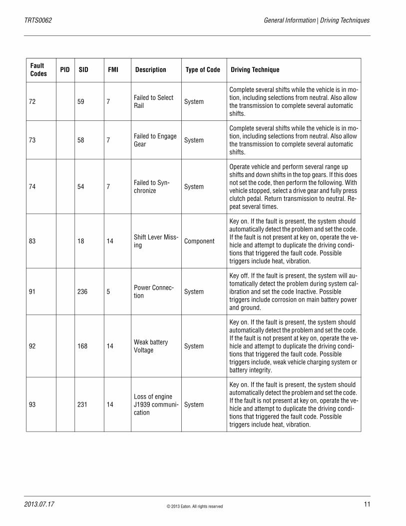
72 59 7 Failed to Select Rail System
Complete several shifts while the vehicle is in mo-tion, including selections from neutral. Also allow the transmission to complete several automatic shifts.
73 58 7 Failed to Engage Gear System
Complete several shifts while the vehicle is in mo-tion, including selections from neutral. Also allow the transmission to complete several automatic shifts.
74 54 7 Failed to Syn-chronize System
Operate vehicle and perform several range up shifts and down shifts in the top gears. If this does not set the code, then perform the following. With vehicle stopped, select a drive gear and fully press clutch pedal. Return transmission to neutral. Re-peat several times.
83 18 14 Shift Lever Miss-ing Component
Key on. If the fault is present, the system should automatically detect the problem and set the code. If the fault is not present at key on, operate the ve-hicle and attempt to duplicate the driving condi-tions that triggered the fault code. Possible triggers include heat, vibration.
91 236 5 Power Connec-tion System
Key off. If the fault is present, the system will au-tomatically detect the problem during system cal-ibration and set the code Inactive. Possible triggers include corrosion on main battery power and ground.
92 168 14 Weak battery Voltage System
Key on. If the fault is present, the system should automatically detect the problem and set the code. If the fault is not present at key on, operate the ve-hicle and attempt to duplicate the driving condi-tions that triggered the fault code. Possible triggers include, weak vehicle charging system or battery integrity.
93 231 14Loss of engine J1939 communi-cation
System
Key on. If the fault is present, the system should automatically detect the problem and set the code. If the fault is not present at key on, operate the ve-hicle and attempt to duplicate the driving condi-tions that triggered the fault code. Possible triggers include heat, vibration.
Fault Codes PID SID FMI Description Type of Code Driving Technique
2013.07.17 © 2013 Eaton. All rights reserved 11
12
Fault Code Isolation Procedure Index | General Information TRTS0062
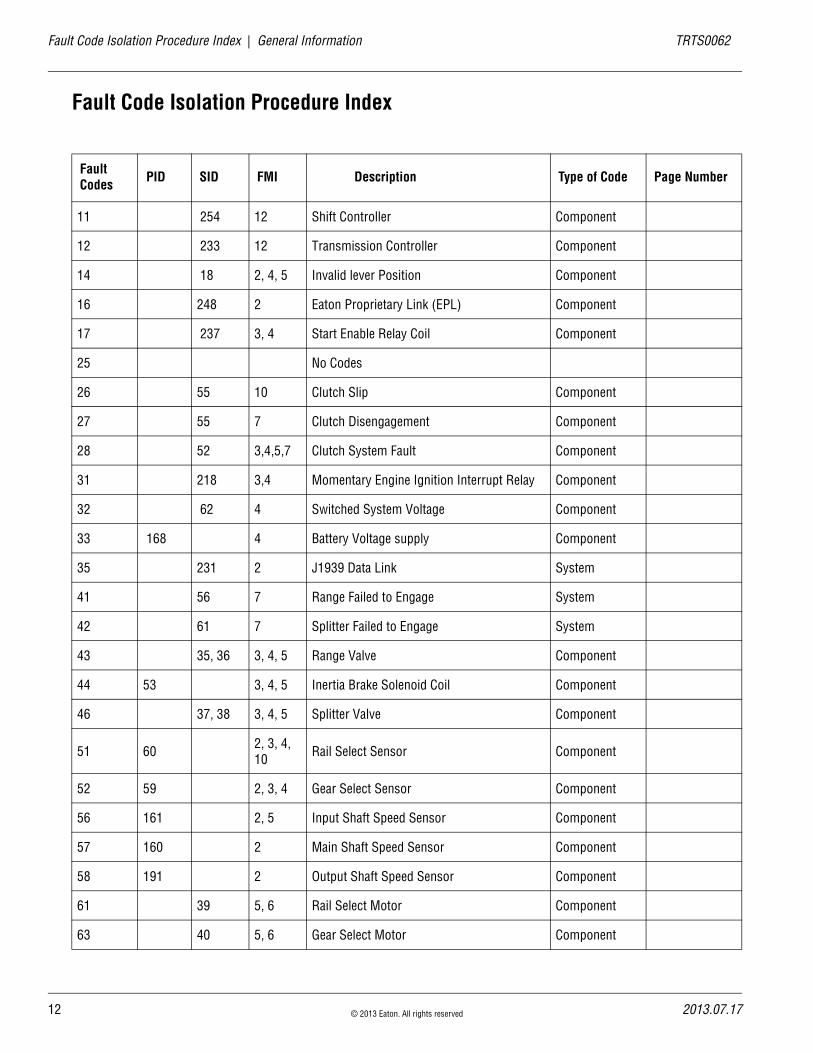
Fault Code Isolation Procedure Index
Fault Codes PID SID FMI Description Type of Code Page Number
11 254 12 Shift Controller Component
12 233 12 Transmission Controller Component
14 18 2, 4, 5 Invalid lever Position Component
16 248 2 Eaton Proprietary Link (EPL) Component
17 237 3, 4 Start Enable Relay Coil Component
25 No Codes
26 55 10 Clutch Slip Component
27 55 7 Clutch Disengagement Component
28 52 3,4,5,7 Clutch System Fault Component
31 218 3,4 Momentary Engine Ignition Interrupt Relay Component
32 62 4 Switched System Voltage Component
33 168 4 Battery Voltage supply Component
35 231 2 J1939 Data Link System
41 56 7 Range Failed to Engage System
42 61 7 Splitter Failed to Engage System
43 35, 36 3, 4, 5 Range Valve Component
44 53 3, 4, 5 Inertia Brake Solenoid Coil Component
46 37, 38 3, 4, 5 Splitter Valve Component
51 60 2, 3, 4, 10 Rail Select Sensor Component
52 59 2, 3, 4 Gear Select Sensor Component
56 161 2, 5 Input Shaft Speed Sensor Component
57 160 2 Main Shaft Speed Sensor Component
58 191 2 Output Shaft Speed Sensor Component
61 39 5, 6 Rail Select Motor Component
63 40 5, 6 Gear Select Motor Component
© 2013 Eaton. All rights reserved 2013.07.17

TRTS0062 General Information | Fault Code Isolation Procedure Index
65 251 4 Logic Power Component
71 60 7 Stuck Engage System
72 59 7 Failed to Select Rail System
73 58 7 Failed to Engage Gear System
74 54 7,10,12 Failed to Synchronize System
83 18 14 Shift Lever Missing System
91 236 5 Power Connection System
92 168 14 Weak System Battery Voltage System
93 231 14 Loss of J1939 Communication from the En-gine System
Fault Codes PID SID FMI Description Type of Code Page Number
2013.07.17 © 2013 Eaton. All rights reserved 13
14 © 2013 Eaton. All rights reserved 2013.07.17
Symptom-Driven Diagnostics Index | General Information TRTS0062
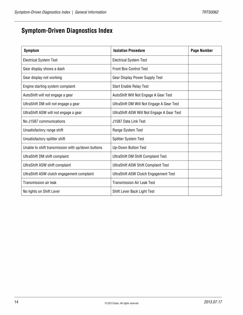
Symptom-Driven Diagnostics Index
Symptom Isolation Procedure Page Number
Electrical System Test Electrical System Test
Gear display shows a dash Front Box Control Test
Gear display not working Gear Display Power Supply Test
Engine starting system complaint Start Enable Relay Test
AutoShift will not engage a gear AutoShift Will Not Engage A Gear Test
UltraShift DM will not engage a gear UltraShift DM Will Not Engage A Gear Test
UltraShift ASW will not engage a gear UltraShift ASW Will Not Engage A Gear Test
No J1587 communications J1587 Data Link Test
Unsatisfactory range shift Range System Test
Unsatisfactory splitter shift Splitter System Test
Unable to shift transmission with up/down buttons Up-Down Button Test
UltraShift DM shift complaint UltraShift DM Shift Complaint Test
UltraShift ASW shift complaint UltraShift ASW Shift Complaint Test
UltraShift ASW clutch engagement complaint UltraShift ASW Clutch Engagement Test
Transmission air leak Transmission Air Leak Test
No lights on Shift Lever Shift Lever Back Light Test
TRTS0062 Electrical Pretest Procedure | Electrical System Pretest
Electrical System Pretest
OverviewThe test does not relate to any specific fault code, but must be completed before performing “Fault Code Isolation Table” procedures. The Electrical Pretest verifies the batter-ies are fully charged.
DetectionThere is no detection process specifically for the basic elec-trical supply; however, failures of this type are generally detected by the transmission or operator as some other fault code or symptom.
FallbackThere is no fallback for the Electrical Pretest; however, it may effect other systems.
Possible Causes This pretest can be used for any of the following:
• Low batteries
• Starter-battery connections
Additional Tools • Basic hand tools
• Eaton Test Adapter kit
• Digital volt/ohm meter
• Battery load tester
2013.07.17 © 2013 Eaton. All rights reserved 15

16
Electrical System Pretest | Electrical Pretest Procedure TRTS0062
Component Identification
VOLTS
VCOM A
+–
+–
© 2013 Eaton. All rights reserved 2013.07.17

TRTS0062 Electrical Pretest Procedure | Electrical System Pretest
Electrical System Pretest
1. Key off.
2. Inspect starter, battery and in-line fuse holder con-nections for integrity.
3. Measure voltage across batteries.
• If voltage is 11–13 volts on a 12-volt system or 22–26 on a 24-volt system, go to Step B.
• If voltage is outside of range, repair or replace batteries and charging system as required. Then measure voltage again.
1. Key off.
2. Load test the Batteries.
• If the batteries maintain the specified load, test complete.
• If the batteries fail the Load Test, replace the damaged battery(s). Go to Step A.
A Purpose: Measure battery voltage, visually inspect batteries.
VOLTS
VCOM A
+–
+–
B Purpose: Verify the batteries pass a load test.
2013.07.17 © 2013 Eaton. All rights reserved 17

18
Power-Up Sequence Pretest | Electrical Pretest Procedure TRTS0062
Power-Up Sequence Pretest
OverviewA failure during the self-check indicates a failure of the Shift Controller.
DetectionThe power-up self-check is performed automatically each time the key is turned on. Turn the key on and watch the Service light. If power up stops with the Service light con-stantly on, or it never comes on, self-check has failed.
FallbackIf self-check fails, the product cannot perform any opera-tions.
Possible Causes This test can be used for the following:
• Shift Controller
• Vehicle Harness
Additional Tools • Basic hand tools
• Eaton Test Adapter kit
• Digital volt/ohm meter
© 2013 Eaton. All rights reserved 2013.07.17

TRTS0062 Electrical Pretest Procedure | Power-Up Sequence Pretest
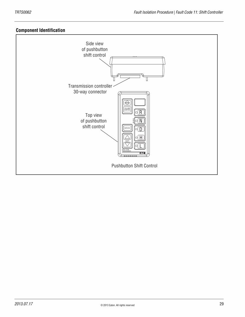
Component Identification
Top viewof pushbuttonshift control
Side viewof pushbuttonshift control
Pushbutton Shift Control
VOLUMECONTROL
SERVICE
SHIFT
Eaton FullerTransmissions
L
H
D
N
R
Transmission controller30-way connector
Eaton Shift Lever
2013.07.17 © 2013 Eaton. All rights reserved 19

20
Power-Up Sequence Pretest | Electrical Pretest Procedure TRTS0062
Power-Up Sequence Pretest
1. Is vehicle equipped with a Shift Lever?
• If vehicle is not equipped with a Shift Lever, go to Step B.
• If vehicle is equipped with a Shift Lever, go to Step D.
1. Key on.
2. Observe Service light.
Note: If Service light is flashing, see “Diagnostic Procedure” on page 4.
• If Service light lights for one second and turns off, Test complete.
• If Service light never comes on, go to Step C.
• If Service light is on steady, replace Shift Con-trol. Repeat this step.
1. Key off.
2. Disconnect Shift Controller 30-way connector.
3. Key on.
4. Measure voltage across batteries and record find-ing.
5. Measure voltage between Shift Controller 30-way Pin C1 and Pin K3.
• If voltage is within 1 volt of battery voltage, replace Shift Control. Go to Step B.
• If voltage is outside of range, no ignition power. Repair ignition power supply to trans-mission, go to Step B.
A Purpose: Visually identify if the vehicle is equipped with a Shift Lever.
B Purpose: Verify proper power up of the transmis-sion shift controller.
C Purpose: Confirm switched ignition voltage to the transmission shift controller.
VOLTS
V COM A
K
J
H
G
F
E
D
C
B
A
3 2 1
3 2 1
© 2013 Eaton. All rights reserved 2013.07.17
TRTS0062 Electrical Pretest Procedure | Power-Up Sequence Pretest
1. Is vehicle equipped with an Eaton-supplied Shift Lever or an OEM-supplied Shift Lever?
• If Eaton Shift Lever, go to Step E.
• If OEM Shift Lever, go to Step I.
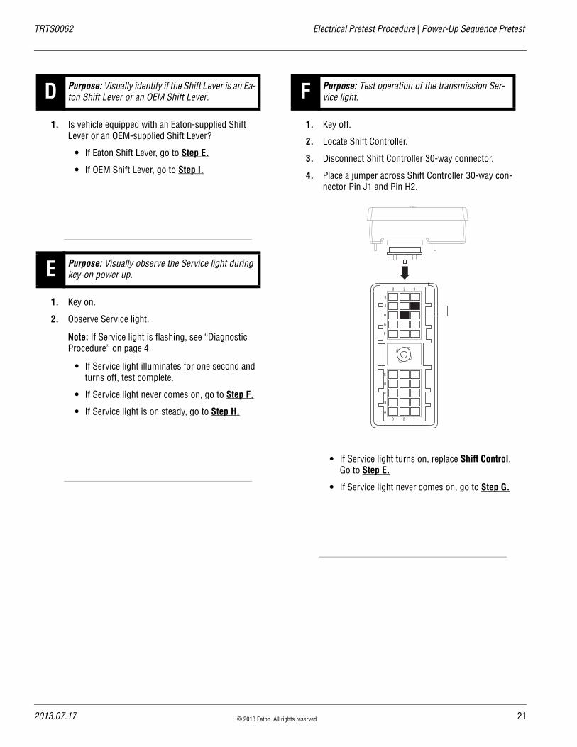
1. Key on.
2. Observe Service light.
Note: If Service light is flashing, see “Diagnostic Procedure” on page 4.
• If Service light illuminates for one second and turns off, test complete.
• If Service light never comes on, go to Step F.
• If Service light is on steady, go to Step H.
1. Key off.
2. Locate Shift Controller.
3. Disconnect Shift Controller 30-way connector.
4. Place a jumper across Shift Controller 30-way con-nector Pin J1 and Pin H2.
• If Service light turns on, replace Shift Control. Go to Step E.
• If Service light never comes on, go to Step G.
D Purpose: Visually identify if the Shift Lever is an Ea-ton Shift Lever or an OEM Shift Lever.
E Purpose: Visually observe the Service light during key-on power up.
F Purpose: Test operation of the transmission Ser-vice light.
K
J
H
G
F
E
D
C
B
A
3 2 1
3 2 1
2013.07.17 © 2013 Eaton. All rights reserved 21

22
Power-Up Sequence Pretest | Electrical Pretest Procedure TRTS0062
1. Key off.
2. Disconnect Shift Lever 8-way connector.
3. Measure resistance between:- Shift Controller 30-way Pin H2 and Shift Lever
8-way connector Pin 6- Shift Controller 30-way connector Pin H2 and
ground.
• If resistance between Pin H2 and Pin 6 is 0–0.3 ohms and If resistance between Pin H2 and ground is 10K ohms or open circuit [OL], replace Shift Lever. Go to Step E.
• If any of the above conditions are not met, repair Vehicle Harness between Shift Control-ler and Shift Lever, go to Step E.
1. Key on.
2. Locate Shift Controller.
3. Disconnect Shift Controller 30-way connector.
• If Service light turns off, replace Shift Control. Go to Step E.
• If Service light remains on, repair OEM har-ness as required. Go to Step E.
1. Key off.
2. Locate Service light connector on Vehicle Harness.
3. Measure voltage across Pin A and Pin B on Service light connector.
4. Key on.
• If voltage is within 2 volts of total battery volt-age for 1 second, then 0 volts, test complete.
• If no voltage is measured, go to Step J.
• If voltage is within 2 volts of battery voltage continuously, go to Step K.
G Purpose: Confirm OEM Service light power wire continuity and test for a short to ground.
OHMS
V COM A
K
J
H
G
F
E
D
C
B
A
3 2 1
3 2 1
1
2
3
4 5
6
7
8
H Purpose: Test the transmission Service light.
I Purpose: Measure battery voltage to the Service light
© 2013 Eaton. All rights reserved 2013.07.17
TRTS0062 Electrical Pretest Procedure | Power-Up Sequence Pretest
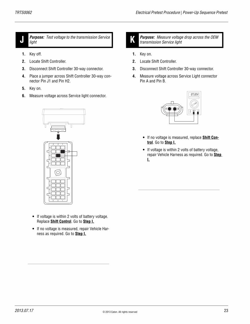
1. Key off.
2. Locate Shift Controller.
3. Disconnect Shift Controller 30-way connector.
4. Place a jumper across Shift Controller 30-way con-nector Pin J1 and Pin H2.
5. Key on.
6. Measure voltage across Service light connector.
• If voltage is within 2 volts of battery voltage. Replace Shift Control. Go to Step I.
• If no voltage is measured, repair Vehicle Har-ness as required. Go to Step I.
1. Key on.
2. Locate Shift Controller.
3. Disconnect Shift Controller 30-way connector.
4. Measure voltage across Service Light connector Pin A and Pin B.
• If no voltage is measured, replace Shift Con-trol. Go to Step I.
• If voltage is within 2 volts of battery voltage, repair Vehicle Harness as required. Go to Step I.
J Purpose: Test voltage to the transmission Service light
K
J
H
G
F
E
D
C
B
A
3 2 1
3 2 1
K Purpose: Measure voltage drop across the OEM transmission Service light
VOLTS
VCOMABA
2013.07.17 © 2013 Eaton. All rights reserved 23
24
Air Pretest | Electrical Pretest Procedure TRTS0062
Air Pretest
OverviewThe pretest does not relate to any specific fault code, but must be completed before performing “Fault Code Isolation Table” procedures. The pretest verifies that the basic air input is OK before testing individual system functions.
DetectionThere is no detection process specifically for the basic air supply; however, failures of this type are generally detected by the transmission or operator as some other type of fault code or symptom.
FallbackThere is no fallback mode for air pretest; however, it may affect other systems.
Possible Causes This pretest can be used for any of the following:
• Low air pressure
• Contaminated air
• Air Filter-Regulator
Additional Tools • Basic hand tools
• 0-100 PSI Air pressure gauge
© 2013 Eaton. All rights reserved 2013.07.17
TRTS0062 Electrical Pretest Procedure | Air Pretest
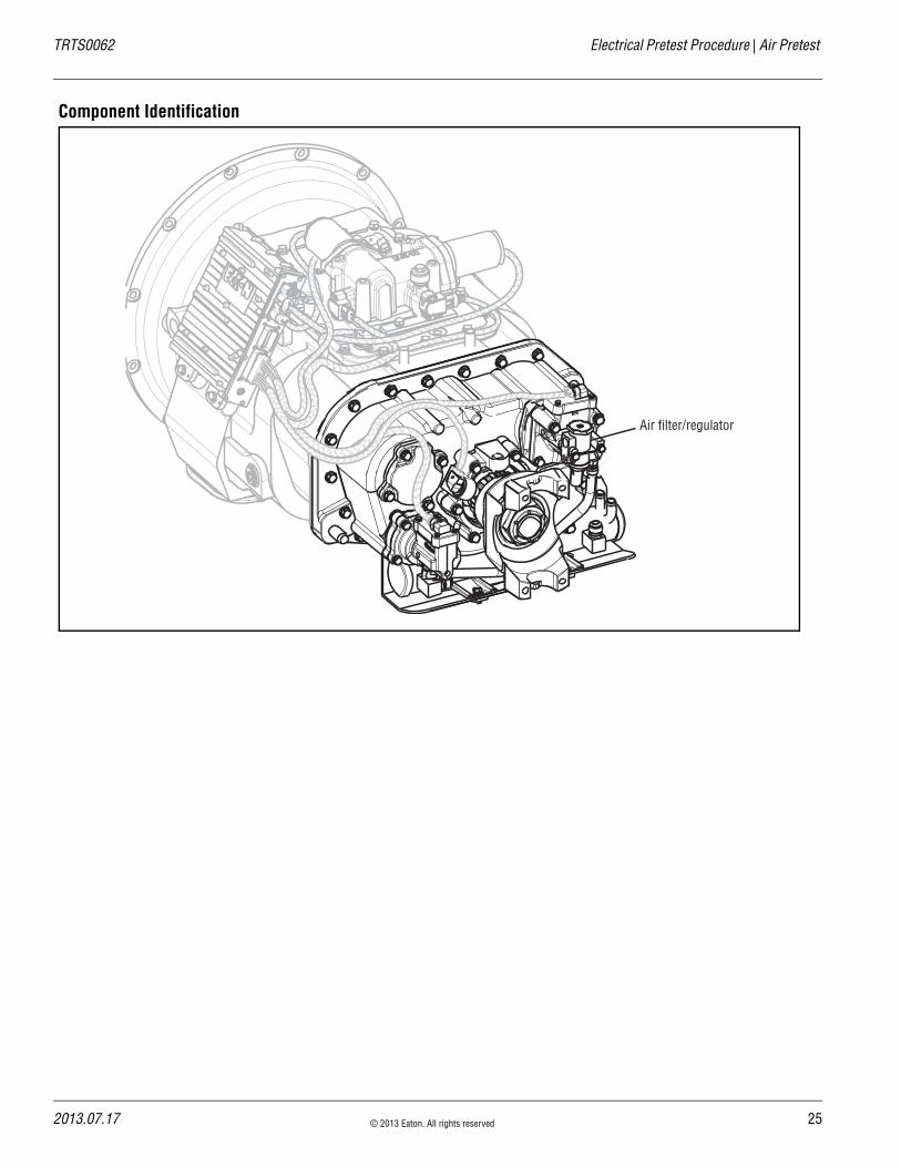
Component Identification
Air filter/regulator
2013.07.17 © 2013 Eaton. All rights reserved 25

26
Air Pretest | Electrical Pretest Procedure TRTS0062
Air Pretest
1. Key off.
2. Install a 0-100 PSI air pressure gauge in the regu-lated test port of the air filter-regulator.
3. Start engine and allow air pressure to build to gov-ernor cut off.
4. Monitor the vehicle air pressure gauge on the dash.
• If air pressure cuts off at 90–120 PSI, go to Step B.
• If air pressure is outside of range, repair vehi-cle air system as required. Repeat this step.
1. Key off.
2. Monitor the vehicle air pressure gauge on the dash.
• If vehicle maintains air pressure, go to Step C.
• If vehicle loses air pressure, repair vehicle air system as required. Repeat this step.
1. Read air pressure gauge installed at the regulated port.
• If air pressure is 55–65 PSI, test complete.
• If air pressure is outside of range, go to Step D.
1. Remove air supply line to the Air Filter-Regulator and check airflow.
• If air flows from the supply line, replace Air Filter-Regulator. Go to Step C.
• If air does not flow from the supply line, repair vehicle air supply to the regulator. Go to Step C.
A Purpose: Verify proper truck system air pressure.
B Purpose: Verify system pressure is maintained.
Regulated test port
0-100 PSI
C Purpose: Confirm air pressure to the Filter Regula-tor Supply port.
D Purpose: Confirm air flow to the Filter-Regulator.
© 2013 Eaton. All rights reserved 2013.07.17

TRTS0062 Electrical Pretest Procedure | Air Pretest
2013.07.17 © 2013 Eaton. All rights reserved 27
28
Fault Code 11: Shift Controller | Fault Isolation Procedure TRTS0062
Fault Code 11: Shift ControllerJ1587 MID: 130 SID:254 FMI:12
OverviewFault Code 11 indicates an internal failure of the Shift Con-troller.
DetectionThe Shift Controller checks the program memory every time the key is turned on. If the Shift Controller detects a failure within the program memory, it sets this fault code.
Conditions to Set Fault Code Active
FallbackThis fault causes an in-place fallback while operating and a self-check failure if it occurs during power up.
Possible Causes This fault code can be caused by any of the following:
• Improper configuration software
• Shift Controller
Additional Tools • Basic hand tools
© 2013 Eaton. All rights reserved 2013.07.17
TRTS0062 Fault Isolation Procedure | Fault Code 11: Shift Controller
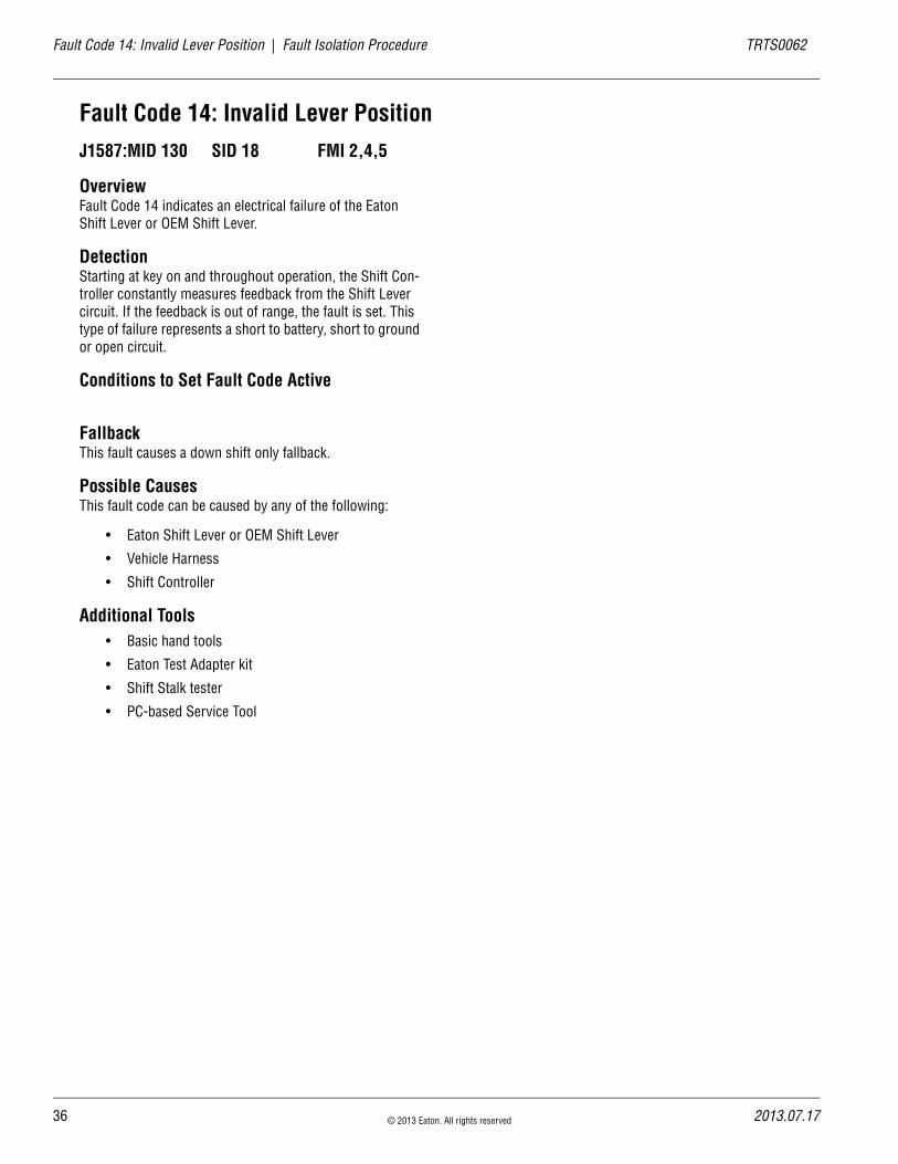
Component Identification
Top viewof pushbuttonshift control
Side viewof pushbuttonshift control
Pushbutton Shift Control
VOLUMECONTROL
SERVICE
SHIFT
Eaton FullerTransmissions
L
H
D
N
R
Transmission controller
30-way connector
2013.07.17 © 2013 Eaton. All rights reserved 29

30
Fault Code 11: Shift Controller Test | Fault Isolation Procedure TRTS0062
Fault Code 11: Shift Controller Test
1. Key on.
2. Retrieve Codes, see “Retrieving Fault Codes” on page 5.
• If Fault Code 11 is Active, replace Shift Con-trol.
• If Fault Code 11 is Inactive, test complete.
A Purpose: Check for Active or Inactive fault codes.
© 2013 Eaton. All rights reserved 2013.07.17

TRTS0062 Fault Isolation Procedure | Fault Code 11: Shift Controller Test
2013.07.17 © 2013 Eaton. All rights reserved 31
32
Fault Code 12: Transmission Controller | Fault Isolation Procedure TRTS0062
Fault Code 12: Transmission ControllerJ1587:MID 130 SID 233 FMI 12
OverviewFault Code 12 indicates an internal failure of the Transmis-sion Controller.
DetectionThe Transmission Controller checks the program memory every time the key is turned on. If the Transmission Control-ler detects a failure within the program memory, it sets this fault code.
Conditions to Set Fault Code Active
FallbackThis fault causes an in-place fallback while moving and a failure during system initialization.
Possible Causes This fault code can be caused by any of the following:
• Improper configuration software
• Transmission controller
Additional Tools • Basic hand tools
© 2013 Eaton. All rights reserved 2013.07.17

TRTS0062 Fault Isolation Procedure | Fault Code 12: Transmission Controller
Component Identification
Transmission controller
2013.07.17 © 2013 Eaton. All rights reserved 33

34
Fault Code 12: Transmission Controller Test | Fault Isolation Procedure TRTS0062
Fault Code 12: Transmission Controller Test
1. Key on.
2. Retrieve codes, see “Retrieving Fault Codes” on page 5.
• If Fault Code 12 is Active, replace Transmis-sion Controller.
• If Fault Code 12 is Inactive, test complete.
A Purpose: Check for Active or Inactive fault codes.
© 2013 Eaton. All rights reserved 2013.07.17

TRTS0062 Fault Isolation Procedure | Fault Code 12: Transmission Controller Test
2013.07.17 © 2013 Eaton. All rights reserved 35
36
Fault Code 14: Invalid Lever Position | Fault Isolation Procedure TRTS0062
Fault Code 14: Invalid Lever PositionJ1587:MID 130 SID 18 FMI 2,4,5
OverviewFault Code 14 indicates an electrical failure of the Eaton Shift Lever or OEM Shift Lever.
DetectionStarting at key on and throughout operation, the Shift Con-troller constantly measures feedback from the Shift Lever circuit. If the feedback is out of range, the fault is set. This type of failure represents a short to battery, short to ground or open circuit.
Conditions to Set Fault Code Active
FallbackThis fault causes a down shift only fallback.
Possible Causes This fault code can be caused by any of the following:
• Eaton Shift Lever or OEM Shift Lever
• Vehicle Harness
• Shift Controller
Additional Tools • Basic hand tools
• Eaton Test Adapter kit
• Shift Stalk tester
• PC-based Service Tool
© 2013 Eaton. All rights reserved 2013.07.17
TRTS0062 Fault Isolation Procedure | Fault Code 14: Invalid Lever Position
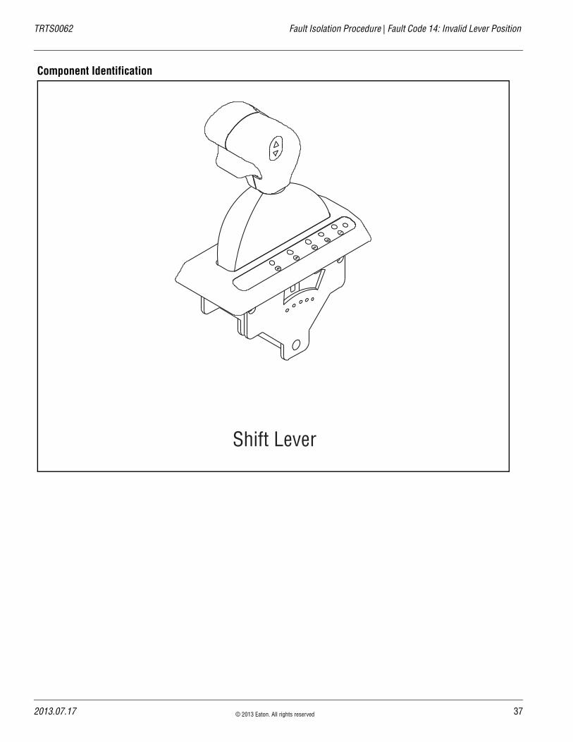
Component Identification
Shift Lever
2013.07.17 © 2013 Eaton. All rights reserved 37

38
Fault Code 14: Invalid Lever Position Test | Fault Isolation Procedure TRTS0062
Fault Code 14: Invalid Lever Position Test
1. Is vehicle equipped with an Eaton-supplied Shift Lever or an OEM-supplied Shift Lever?
• If Eaton Shift Lever, go to Step B.
• If OEM Shift Lever, go to Step F.
1. Key off.
2. Disconnect Shift Lever 8-way connector.
3. Connect Shift Lever tester to the 8-way Shift Lever harness.
4. Connect PC-based Service Tool to diagnostic port.
5. Key on.
6. Select “Monitor Data.”
7. Observe transmission range attained.
• If transmission range attained equals neutral, replace Shift Lever (only if fault code is Active). Go to Step V.
• If transmission range attained does not equal neutral, go to Step C.
1. Key off.
2. Locate Shift Controller.
3. Disconnect Shift Controller 30-way connector.
4. Measure resistance between:- Shift Controller 30-way Pin D1 and Shift Lever
8-way connector Pin 1- Shift Controller 30-way connector Pin D1 and
ground
• If resistance between Pin D1 and Pin 1 is 0–0.3 ohms, and if resistance between Pin D1 and ground is 10K ohms or open circuit [OL], go to Step D.
• If any of the above conditions are not met, repair Shift Lever Harness between Shift Con-troller and Shift Lever. Go to Step V.
A Purpose: Visually identify if the Shift Lever is an Eaton Shift Lever or an OEM Shift Lever.
B Purpose: Confirm OEM Shift Lever Harness integ-rity.
C Purpose: Verify continuity of the OEM Shift Lever Harness. Test for a short to ground.
OHMS
V COM A
K
J
H
G
F
E
D
C
B
A
3 2 1
3 2 1
1
2
3
4 5
6
7
8
© 2013 Eaton. All rights reserved 2013.07.17

TRTS0062 Fault Isolation Procedure | Fault Code 14: Invalid Lever Position Test
1. Key off.
2. Disconnect Shift Controller 30-way connector.
3. Measure resistance between: - Shift Controller 30-way Pin D2 and Shift Lever
8-way connector Pin 8- Shift Controller 30-way connector Pin D2 and
ground
• If resistance between Pin D2 and Pin 8 is 0–0.3 ohms, and if resistance between Pin D2 and ground is 10K ohms or open circuit [OL], go to Step E.
• If any of the above conditions are not met, repair Shift Lever Harness between the Shift Controller and Shift Lever. Go to Step V.
1. Key off.
2. Disconnect Shift Controller 30-way connector.
3. Measure resistance between:- Shift Controller 30-way Pin D3 and Shift Lever
8-way connector Pin 2- Shift Controller 30-way connector Pin D3 and
ground
• If resistance between Pin D3 and Pin 2 is 0–0.3 ohms and if resistance between Pin D3 and ground is 10K ohms or open circuit [OL], replace Shift Control. Go to Step V.
• If any of the above conditions are not met, repair Shift Lever Harness between Shift Con-troller and Shift Lever. Go to Step V.
D Purpose: Verify continuity of the OEM Shift Lever Harness, and test for a short to ground.
OHMS
V COM A
K
J
H
G
F
E
D
C
B
A
3 2 1
3 2 1
1
2
3
4 5
6
7
8
E Purpose: Verify continuity of the OEM Shift Lever Harness, and test for a short to ground.
OHMS
V COM A
K
J
H
G
F
E
D
C
B
A
3 2 1
13 2
1
2
3
4 5
6
7
8
2013.07.17 © 2013 Eaton. All rights reserved 39
40
Fault Code 14: Invalid Lever Position Test | Fault Isolation Procedure TRTS0062
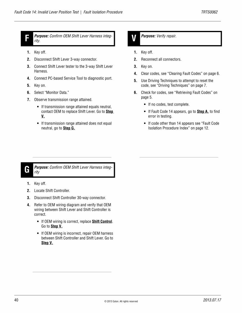
1. Key off.
2. Disconnect Shift Lever 3-way connector.
3. Connect Shift Lever tester to the 3-way Shift Lever Harness.
4. Connect PC-based Service Tool to diagnostic port.
5. Key on.
6. Select “Monitor Data.”
7. Observe transmission range attained.
• If transmission range attained equals neutral, contact OEM to replace Shift Lever. Go to Step V.
• If transmission range attained does not equal neutral, go to Step G.
1. Key off.
2. Locate Shift Controller.
3. Disconnect Shift Controller 30-way connector.
4. Refer to OEM wiring diagram and verify that OEM wiring between Shift Lever and Shift Controller is correct.
• If OEM wiring is correct, replace Shift Control. Go to Step V.
• If OEM wiring is incorrect, repair OEM harness between Shift Controller and Shift Lever. Go to Step V.
1. Key off.
2. Reconnect all connectors.
3. Key on.
4. Clear codes, see “Clearing Fault Codes” on page 6.
5. Use Driving Techniques to attempt to reset the code, see “Driving Techniques” on page 7.
6. Check for codes, see “Retrieving Fault Codes” on page 5.
• If no codes, test complete.
• If Fault Code 14 appears, go to Step A. to find error in testing.
• If code other than 14 appears see “Fault Code Isolation Procedure Index” on page 12.
F Purpose: Confirm OEM Shift Lever Harness integ-rity.
G Purpose: Confirm OEM Shift Lever Harness integ-rity
V Purpose: Verify repair.
© 2013 Eaton. All rights reserved 2013.07.17

TRTS0062 Fault Isolation Procedure | Fault Code 14: Invalid Lever Position Test
2013.07.17 © 2013 Eaton. All rights reserved 41

42
Fault Code 16: Eaton Proprietary Link (EPL) | Fault Isolation Procedure TRTS0062
Fault Code 16: Eaton Proprietary Link (EPL)J1587:MID 130 SID 248 FMI 2
OverviewFault Code 16 indicates the Shift Controller and the Trans-mission Controller are unable to communicate.
DetectionStarting at key on and throughout operation, the Shift Con-troller constantly communicates with the Transmission Controller. If a communication failure occurs for more than 5 seconds, Fault Code 16 is set.
Conditions to Set Fault Code Active
FallbackThis fault causes an in-place fallback while operating and a failure during system initialization.
Possible Causes This fault code can be caused by any of the following:
• Vehicle Harness
• Transmission Controller
• Shift Controller
Additional Tools • Basic hand tools
• Eaton Test Adapter kit
• Digital volt/ohm meter
© 2013 Eaton. All rights reserved 2013.07.17

TRTS0062 Fault Isolation Procedure | Fault Code 16: Eaton Proprietary Link (EPL)
Component Identification
Vehicle bulkhead connector
EPL Data LinkF1
F2
F3
C1
C2
C3
(C1, C2, C3) = Communication from and to the controller
Vehicle interface18-way connector
Shift control30-way connector
2013.07.17 © 2013 Eaton. All rights reserved 43

44
Fault Code 16: Eaton Proprietary Link (EPL) Test | Fault Isolation Procedure TRTS0062
Fault Code 16: Eaton Proprietary Link (EPL) Test
1. Key off.
2. Inspect main power 2-way connector terminals, in-line fuse holder and power supply connections for integrity and corrosion.
• If no problem found, go to Step B.
• If problem is found, repair power or ground path for the main power supply. Go to Step V.
1. Key off.
2. Insert 20-amp fuse into main power 2-way connec-tor.
• If fuse blows immediately, go to Step C.
• If fuse does not blow immediately, repair wir-ing from the battery to the Transmission Con-troller. Go to Step V.
A Purpose: Visually inspect the integrity of the fuse holder and connections.
A B
+–
+–
+–
+–
B Purpose: Verify the Vehicle Harness will carry a proper load.
Main Power Supply 2-Way Connector20 Amp Fuse
30 Amp Fuse
© 2013 Eaton. All rights reserved 2013.07.17

TRTS0062 Fault Isolation Procedure | Fault Code 16: Eaton Proprietary Link (EPL) Test
1. Key off.
2. Disconnect Shift Controller 30-way connector.
3. Disconnect Vehicle Interface 18-way connector.
4. Measure resistance between:- Shift Controller 30-way connector Pin F1 and
vehicle interface 18-way connector Pin C1- Shift Controller 30-way connector Pin F1 and
ground
• If resistance between Pin F1 and Pin C1 is 0–0.3 ohms and if resistance between Pin F1 and ground is 10K ohms or open circuit [OL], go to Step D.
• If any of the above conditions are not met, repair Vehicle Harness between the Transmis-sion Controller and Shift Controller. Go to Step V.
C Purpose: Verify continuity of the OEM interface harness, and test for a short to ground.
K
J
H
G
F
E
D
C
B
A
3 2 1
3 2 1
D
E
F
1 2 3
A
B
C
1 2 3
OHMS
V COM A
K
J
H
G
F
E
D
C
B
A
3 2 1
OHMS
V COM A
GROUND
2013.07.17 © 2013 Eaton. All rights reserved 45
46
Fault Code 16: Eaton Proprietary Link (EPL) Test | Fault Isolation Procedure TRTS0062
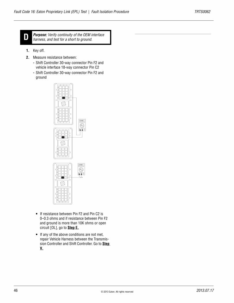
1. Key off.
2. Measure resistance between: - Shift Controller 30-way connector Pin F2 and
vehicle interface 18-way connector Pin C2- Shift Controller 30-way connector Pin F2 and
ground
• If resistance between Pin F2 and Pin C2 is 0–0.3 ohms and if resistance between Pin F2 and ground is more than 10K ohms or open circuit [OL], go to Step E.
• If any of the above conditions are not met, repair Vehicle Harness between the Transmis-sion Controller and Shift Controller. Go to Step V.
D Purpose: Verify continuity of the OEM interface harness, and test for a short to ground.
K
J
H
G
F
E
D
C
B
A
3 2 1
3 2 1
D
E
F
1 2 3
A
B
C
1 2 3
OHMS
V COM A
K
J
H
G
F
E
D
C
B
A
3 2 1
OHMS
V COM A
GROUND
© 2013 Eaton. All rights reserved 2013.07.17

TRTS0062 Fault Isolation Procedure | Fault Code 16: Eaton Proprietary Link (EPL) Test
1. Key off.
2. Measure resistance between:- Shift Controller 30-way connector Pin F3 and
Vehicle Harness 18-way connector Pin C3- Shift Controller 30-way connector Pin F3 and
ground
• If resistance between Pin F3 and Pin C3 is 0–0.3 ohms, and if resistance between Pins F2 and ground is more than 10K ohms or open, go to Step V.
If the above conditions are not met, repair Vehicle Harness between the Transmission Controller and Shift Controller. Go to Step V.
1. Key off.
2. Reconnect all connectors.
3. Key on.
4. Clear codes, see “Clearing Fault Codes” on page 6.
5. Use the “Driving Techniques” section of this book to attempt to reset the code, see “Driving Tech-niques” on page 7.
6. Check for codes, see “Retrieving Fault Codes” on page 5.
• If no codes, Test complete.
• If Fault Code 16 appears, go to Step A. to find error in testing.
• If a code other than 16 appears, see “Fault Code Isolation Procedure Index” on page 12.
E Purpose: Verify continuity of the Vehicle Harness, and test for a short to ground.
K
J
H
G
F
E
D
C
B
A
3 2 1
3 2 1
D
E
F
1 2 3
A
B
C
1 2 3
OHMS
V COM A
K
J
H
G
F
E
D
C
B
A
3 2 1
OHMS
V COM A
GROUND
V Purpose: Verify repair.
2013.07.17 © 2013 Eaton. All rights reserved 47
48
Fault Code 17: Start Enable Relay Coil | Fault Isolation Procedure TRTS0062
Fault Code 17: Start Enable Relay CoilJ1587:MID 130 SID 237 FMI 3,4
OverviewFault Code 17 indicates an electrical failure of the relay that allows the engine to start after start-up conditions are met.
DetectionStarting at key on and throughout operation, the Shift Con-troller constantly measures the circuit. If a condition of short to battery, short to ground or open circuit is detected, Fault Code 17 is set.
Conditions to Set Fault Code Active
FallbackThe Start Enable Relay has no fallback; however, if the fail-ure occurred before the engine was started, it is possible the engine will not start.
Possible Causes This fault code can be caused by any of the following:
• Relay Coil Open
• Vehicle Harness
• Shift Controller
• Operator too quick on key (not waiting for a “N”)
Additional Tools • Basic hand tools
• Eaton Test Adapter kit
• Digital volt/ohm meter
© 2013 Eaton. All rights reserved 2013.07.17

TRTS0062 Fault Isolation Procedure | Fault Code 17: Start Enable Relay Coil
Component Identification
Startenable relay
Run to startsignal from
ignition switch
Run tostarter solenoid
A2
C3
A3
30
87
86
85
30
86
8785
All OEM responsible wiring shown is "typical". Consult specific application.(C3, 30, 86, Run to Solenoid) = +12 volt non-switched from battery (A2, 87) = Signals into the controller (A3, 85) = Signal returns, grounds, and general OEM wiring
Shift control 30-way connector
2013.07.17 © 2013 Eaton. All rights reserved 49
50
Fault Code 17: Start Enable Relay Coil Test | Fault Isolation Procedure TRTS0062
Fault Code 17: Start Enable Relay Coil Test
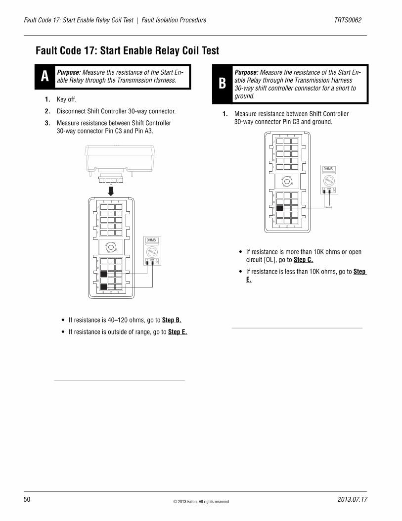
1. Key off.
2. Disconnect Shift Controller 30-way connector.
3. Measure resistance between Shift Controller 30-way connector Pin C3 and Pin A3.
• If resistance is 40–120 ohms, go to Step B.
• If resistance is outside of range, go to Step E.
1. Measure resistance between Shift Controller 30-way connector Pin C3 and ground.
• If resistance is more than 10K ohms or open circuit [OL], go to Step C.
• If resistance is less than 10K ohms, go to Step E.
A Purpose: Measure the resistance of the Start En-able Relay through the Transmission Harness.
OHMS
V COM A
J
I
H
G
F
E
D
C
B
A
3 2 1
3 2 1
BPurpose: Measure the resistance of the Start En-able Relay through the Transmission Harness 30-way shift controller connector for a short to ground.
OHMS
V COM A
J
I
H
G
F
E
D
C
B
A
3 2 1
3 2 1
GROUND
© 2013 Eaton. All rights reserved 2013.07.17

TRTS0062 Fault Isolation Procedure | Fault Code 17: Start Enable Relay Coil Test
1. Disconnect the start enable relay.
2. Measure resistance between Pin 87 of the Start Enable Relay connector and Pin A2 of the Shift Controller 30-way connector, and Pin 87 of the Start Enable Relay connector to the Starter Sole-noid.
• If resistance is 0–0.3 ohms on both readings, go to Step D.
• If resistance is greater than 10K ohms, repair wiring. Go to Step V.
1. Make sure the Start Enable Relay has been discon-nected before putting the key in the start position. Place key in start position.
2. Measure voltage at Pin 30 in the Start Enable Relay connector.
• If voltage is within 0.6 volts of battery voltage, replace Shift Control (only if fault code is Active). Go to Step V.
• If voltage is outside of range, repair wiring. Go to Step V.
1. Remove Start Enable Relay from Vehicle Harness.
2. Measure resistance between Start Enable Relay Pin 85 and Pin 86.
• If resistance is 40–120 ohms, repair OEM wir-ing from Shift Controller to Start Enable Relay. Go to Step V.
• If resistance is outside of range, replace Start Enable Relay. Go to Step V.
C Purpose: Verify continuity of the Start Enable Re-lay wire, and check for a short to ground.
85
30
86
87
87a
OHMS
V COM A
OHMS
V COM A
J
I
H
G
F
E
D
C
B
A
3 2 1
3 2 1
Starter Solenoid
85
30
86
87
87a
D Purpose: Measure signal voltage at the Start En-able Relay connector.
E Purpose: Measure the resistance of the Start En-able Relay at the relay pins.
85
30
86
87
87a
OHMS
V COM A
2013.07.17 © 2013 Eaton. All rights reserved 51

52
Fault Code 17: Start Enable Relay Coil Test | Fault Isolation Procedure TRTS0062
1. Key off.
2. Reconnect all connectors.
3. Key on.
4. Clear codes, see “Clearing Fault Codes” on page 6.
5. Use Driving Techniques to attempt to reset the code, see “Driving Techniques” on page 7.
6. Check for codes, see “Retrieving Fault Codes” on page 5.
• If no codes, test complete.
• If Fault Code 17 appears, go to Step A. to find error in testing.
• If code other than 17 appears, see “Fault Code Isolation Procedure Index” on page 12.
V Purpose: Verify repair.
© 2013 Eaton. All rights reserved 2013.07.17

TRTS0062 Fault Isolation Procedure | Fault Code 17: Start Enable Relay Coil Test
2013.07.17 © 2013 Eaton. All rights reserved 53
54
Fault Code 26: Clutch Slip | Fault Isolation Procedure TRTS0062
Fault Code 26: Clutch SlipJ1587:MID 130 SID 55 FMI 10
OverviewFault Code 26 indicates the clutch is not performing as expected. The Transmission Controller detected excessive clutch slip.
DetectionWhen the transmission is in gear and the clutch is fully engaged, engine speed and Input Shaft speed are com-pared. If the engine speed is significantly different from the Input Shaft speed for a period of 1 second, the Fault Code is set.
Conditions to Set Fault Code Active
FallbackThis fault causes a down-shift fallback. Once the vehicle is stopped, starting gear and reverse gear can be engaged. The fault will clear at power down and up shifts will be allowed until the fault is detected again.
Possible Causes This fault code can be caused by any of the following:
• Worn or broken clutch
Additional Tools • Basic hand tools
• Eaton Test Adapter kit
• Clutch jack
© 2013 Eaton. All rights reserved 2013.07.17

TRTS0062 Fault Isolation Procedure | Fault Code 26: Clutch Slip
Component Identification
Clutch Assembly
Driven Disc
Driven Disc and Intermediate Plate
2013.07.17 © 2013 Eaton. All rights reserved 55

56
Fault Code 26: Clutch Slip Test | Fault Isolation Procedure TRTS0062
Fault Code 26: Clutch Slip Test
1. Key on.
2. Start engine
3. Drive vehicle under load in highest gear possible with engine speed above 1500 RPM. At a steady speed, quickly and fully press and hold the throttle.
• If Fault Code 26 is Active, replace clutch.
• If Fault Code 26 is not Active, test complete.
A Purpose: Check for Active or Inactive fault codes.
© 2013 Eaton. All rights reserved 2013.07.17
TRTS0062 Fault Isolation Procedure | Fault Code 26: Clutch Slip Test
2013.07.17 © 2013 Eaton. All rights reserved 57
58
Fault Code 27: Clutch Disengagement | Fault Isolation Procedure TRTS0062
Fault Code 27: Clutch DisengagementJ1587:MID 130 SID 55 FMI 7
OverviewFault Code 27 indicates the clutch has not disengaged as expected.
DetectionStarting at key on and throughout operation, the Shift Con-troller constantly measures engine RPM and idle torque from the engine.
When engaging a start gear, if the engine speed falls signifi-cantly below idle or engine torque rises significantly above idle torque the fault is set.
If in gear and the vehicle is brought to a stop and engine speed falls significantly below idle, the fault is set.
Conditions to Set Fault Code Active
FallbackThere is no fallback associated with this failure; however, it may be difficult to achieve gear engagement or disengage-ment.
Possible Causes This fault code can be caused by any of the following:
• Worn or broken clutch
Additional Tools • Basic hand tools
• Eaton Test Adapter kit
• Clutch jack
© 2013 Eaton. All rights reserved 2013.07.17
TRTS0062 Fault Isolation Procedure | Fault Code 27: Clutch Disengagement
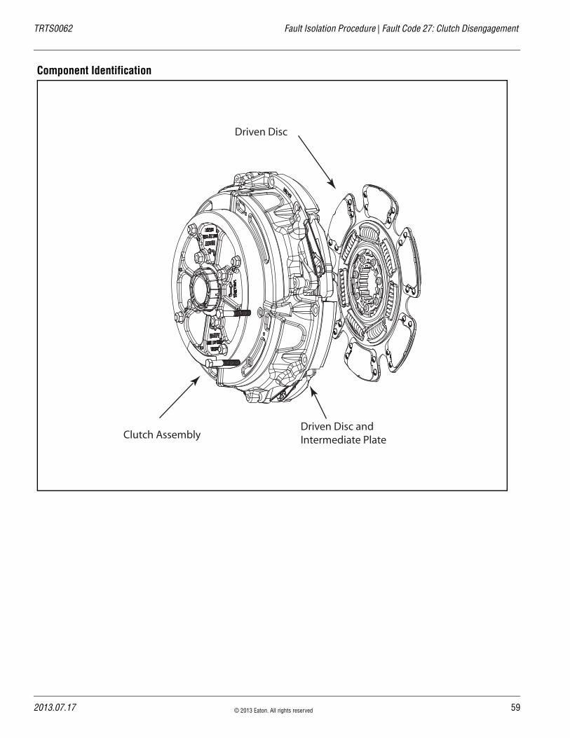
Component Identification
Clutch Assembly
Driven Disc
Driven Disc and Intermediate Plate
2013.07.17 © 2013 Eaton. All rights reserved 59

60
Fault Code 27: Clutch Disengagement Test | Fault Isolation Procedure TRTS0062
Fault Code 27: Clutch Disengagement Test
1. Key on.
2. Start engine.
3. Compare engine RPM to Input Shaft RPM with Ser-viceRanger.
Note: Engine idle RPM must be 700 RPM or lower.
• If the speeds match at idle and Fault Code 27 is Active, replace the clutch.
• If they do not match, test complete.
A Purpose: Monitor transmission Input Shaft speed in ServiceRanger.
© 2013 Eaton. All rights reserved 2013.07.17
TRTS0062 Fault Isolation Procedure | Fault Code 27: Clutch Disengagement Test
2013.07.17 © 2013 Eaton. All rights reserved 61
62
Fault Code 28: Clutch System Fault | Fault Isolation Procedure TRTS0062
Fault Code 28: Clutch System FaultJ1587:MID 130 SID 52 FMI 3, 4, 5, 7
OverviewFault Code 28 indicates either an electrical or mechanical failure in the wet clutch system.
DetectionStarting at key on and throughout operation, the Transmis-sion Controller constantly monitors this circuit. A failure of short to battery, short to ground or open circuit sets the fault code Active.
When the wet clutch is locked after urge to move, engine speed and Input Shaft speeds are compared. If the engine speed is significantly higher than the Input Shaft speed for a period of 5 seconds, the wet clutch is slipping.
Conditions to Set Fault Code Active
FallbackThere is no fallback mode; however, if the failure mode is open circuit, the engine will be disengaged from the Input Shaft.
Possible Causes This fault code can be caused by any of the following:
• Transmission Controller
• Transmission Harness
• Low fluid level
• Wet clutch system
Additional Tools • Basic hand tools
• Digital volt/ohm meter
• Eaton Test Adapter kit
© 2013 Eaton. All rights reserved 2013.07.17

TRTS0062 Fault Isolation Procedure | Fault Code 28: Clutch System Fault
Component Identification
Transmission
Tramsmission30-way Connector
TransmissionController
2013.07.17 © 2013 Eaton. All rights reserved 63

64
Fault Code 28: Clutch System Fault Test | Fault Isolation Procedure TRTS0062
Fault Code 28: Clutch System Fault Test
1. Key on.
2. Place the transmission in neutral.
3. Allow engine to idle at 700–800 RPM for a mini-mum of 2 minutes.
Note: Ensure transmission fluid temperature is 60° –120° F (16°–49° C).
4. Check wet clutch fluid level.
• If fluid level is at or above the Cold-Full mark, go to Step B.
• If fluid level is below the Cold-Add mark, cor-rect fluid level. Go to Step V.
1. Key off.
2. Disconnect the Transmission Controller 30-way connector.
3. Measure resistance between the Transmission Har-ness 30-way connector:- Pin K2 and Pin K3- Pin J2 and Pin J3
• If the resistance between Pin K2 and Pin K3 is 6.5–9.5 ohms and the resistance between Pin J2 and Pin J3 is 8.5–12 ohms, go to Step C.
• If resistance is outside of range, go to Step D.
A Purpose: Check wet clutch fluid level. B Purpose: Measure the resistance of the hydraulic manifold through the Transmission Harness.
OHMS
V COM A
K
J
H
G
F
E
D
C
B
A
3 2 1
3 2 1
OHMS
V COM A
K
J
H
G
F
E
D
C
B
A
3 2 1
3 2 1
© 2013 Eaton. All rights reserved 2013.07.17

TRTS0062 Fault Isolation Procedure | Fault Code 28: Clutch System Fault Test
1. Measure resistance between the Transmission Har-ness 30-way connector:- Pin K2 and ground- Pin J2 and ground
• If resistance from Pin K2 to ground and Pin J2 to ground is more than 10K ohms or open cir-cuit [OL], Replace Transmission (Only if Fault Code is Active). Go to Step V.
• If resistance is less than 10K ohms, go to Step D.
1. Disconnect Transmission Harness located on left side of wet clutch housing.
2. Measure resistance between wet clutch housing connector pins: - Pin 3 and Pin 4- Pin 1 and Pin 2
• If the resistance between Pin 1 and Pin 2 is 8.5–12 ohms and the resistance between Pin 3 and Pin 4 is 6.5–9.5 ohms, go to Step E.
• If resistance is outside of range, replace Transmission. Go to Step V.
C Purpose: Test the Hydraulic Manifold for a short to ground through the Transmission Harness.
OHMS
V COM A
K
J
H
G
F
E
D
C
B
A
3 2 1
3 2 1
OHMS
V COM A
K
J
H
G
F
E
D
C
B
A
3 2 1
3 2 1
GROUND
GROUND
D Purpose: Measure the resistance of the hydraulic manifold switch.
OHMS
V COM A
OHMS
V COM A
4
3 2
1 4
3 2
1
2013.07.17 © 2013 Eaton. All rights reserved 65

66
Fault Code 28: Clutch System Fault Test | Fault Isolation Procedure TRTS0062
1. Measure resistance between wet clutch housing connector pins:- Pin 3 and ground- Pin 1 and ground
• If resistance from Pin 3 to ground and Pin 1 to ground is more than 10K ohms or open circuit [OL], replace Transmission Harness, Go to Step V.
• If resistance is less than 10K ohms, replace Transmission. Go to Step V.
1. Key off.
2. Reconnect all connectors.
3. Key on.
4. Clear codes, see “Clearing Fault Codes” on page 6.
5. Use Driving Techniques to attempt to reset the code, see “Driving Techniques” on page 7.
6. Check for codes, see “Retrieving Fault Codes” on page 5.
• If no codes, test complete.
• If Fault Code 28 appears, go to Step A. to find error in testing.
• If code other than 28 appears, see “Fault Code Isolation Procedure Index” on page 12.
E Purpose: Test the Hydraulic Manifold Switch for a short to ground.
OHMS
V COM A
OHMS
V COM A
4
3 2
1 4
3 2
1
GROUND
GROUND
V Purpose: Verify repair.
© 2013 Eaton. All rights reserved 2013.07.17
TRTS0062 Fault Isolation Procedure | Fault Code 28: Clutch System Fault Test
2013.07.17 © 2013 Eaton. All rights reserved 67

68
Fault Code 31: Momentary Engine Ignition Interrupt Relay (MEIIR) | Fault Isolation Procedure TRTS0062
Fault Code 31: Momentary Engine Ignition Interrupt Relay (MEIIR)J1587:MID 130 SID 218 FMI 3,4
OverviewFault Code 31indicates an electrical failure of the Momen-tary Engine Ignition Interrupt Relay (MEIIR) circuit.
DetectionThe fault is detected during power up. The Shift Controller checks the MEIIR circuit every time the system is powered up. If the electrical characteristics of the circuit are incor-rect, the fault code is set.
Conditions to Set Fault Code Active
FallbackThere is no fallback associated with this failure; however, if the engine speed flares uncontrollably while the transmis-sion is in a gear, the transmission may not be able to achieve neutral if it is selected due to a torque lock condi-tion.
Possible Causes This fault code can be caused by any of the following:
• OEM wiring
• Electrical failure in the MEIIR circuit
• Mechanical failure in the MEIIR relay
• Shift Controller
Additional Tools • Basic hand tools
• Eaton Test Adapter kit
• ServiceRanger
© 2013 Eaton. All rights reserved 2013.07.17

TRTS0062 Fault Isolation Procedure | Fault Code 31: Momentary Engine Ignition Interrupt Relay (MEIIR)
Component Identification
Push Button Shift Control
IgnitionInterrupt
relay
30
86
87a
85
Engine ECM
87
30
86
85
87
87a
Gear display
123 4
Ignition power (switched power)run to main power lead thatfeeds the ignition bus (OEM responsible for overcurrent
protection on this line)
10 AMP 12 volt onlyautomatic resetting
circuit breakerOr
10 or 15 AMPfuse
C1
H1
H3
Run to ignitioninput on Engine
ECM
All OEM responsible wiring shown is "typical". Consult specific application.(C1,Ignition Power, 30, 86, 87a) = +12 volt switched from ignition switch(H3-87) = Signal returns(H1-85) = -12 volt relay source
2013.07.17 © 2013 Eaton. All rights reserved 69

70
Fault Code 31: Momentary Engine Ignition Interrupt Relay (MEIIR) Test | Fault Isolation Procedure TRTS0062
Fault Code 31: Momentary Engine Ignition Interrupt Relay (MEIIR) Test
1. Key off.
2. Disconnect Shift Controller 30-way connector.
3. Remove the MEIIR relay from OEM Dash Harness.
4. Measure resistance between:- Shift Controller 30-way connector Pin H1 and
relay connector Pin 85.- Shift Controller 30-way connector Pin H1 and
ground.
• If resistance between Pin H1 and Pin 85 is 0–0.3 ohms and if resistance between Pin H1 and ground is between 10K ohms and open circuit [OL], go to Step B.
• If resistance is outside of range, repair OEM wiring from Shift Controller to MEIIR relay. Go to Step V.
1. Key off.
2. Measure resistance between:- Shift Controller 30-way connector Pin H3 and
relay connector Pin 87.- Shift Controller 30-way connector Pin H3 and
ground.
• If resistance between Pin H3 and Pin 87 is 0–0.3 ohms and if resistance between Pin H3 and ground is 10K ohms or open circuit [OL], go to Step C.
• If resistance is outside of range, repair OEM wiring from Shift Controller to MEIIR relay. Go to Step V.
A Purpose: Verify continuity of the Vehicle Harness and test for a short to ground.
OHMS
V COM AJ
I
H
G
F
E
D
C
B
A
3 2 1
3 2 1
85
30
86
87
87a
J
I
H
G
F
E
D
C
B
A
3 2 1
3 2 1
Ground
OHMS
V COM A
B Purpose: Verify continuity of the OEM Vehicle har-ness and test for a short to ground.
OHMS
V COM AJ
I
H
G
F
E
D
C
B
A
3 2 1
3 2 1
85
30
86
87
87a
J
I
H
G
F
E
D
C
B
A
3 2 1
3 2 1
Ground
OHMS
V COM A
© 2013 Eaton. All rights reserved 2013.07.17

TRTS0062 Fault Isolation Procedure | Fault Code 31: Momentary Engine Ignition Interrupt Relay (MEIIR) Test
1. Reconnect Shift Controller 30-way connector.
2. Key on.
3. Measure voltage between MEIIR relay connector Pin 86 and ground
• If voltage is within 0.6 of battery voltage, go to Step D.
• If voltage is outside of range, repair OEM wir-ing. Go to Step V.
1. Key on.
2. Measure voltage between MEIIR relay connector Pin 30 and ground.
• If voltage is within 0.6 of battery voltage, Replace MEIIR relay (only if fault code is Active), Go to Step E.
• If resistance is outside of range, repair OEM wiring, Go to Step V.
C Purpose: Measure signal voltage at the MEIIR re-lay connector.
85
30
86
87
87a
OHMS
V COM A
Ground
D Purpose: Measure battery voltage to the MEIIR re-lay.
85
30
86
87
87a
OHMS
V COM A
Ground
2013.07.17 © 2013 Eaton. All rights reserved 71

72
Fault Code 31: Momentary Engine Ignition Interrupt Relay (MEIIR) Test | Fault Isolation Procedure TRTS0062
1. Key on.
2. Retrieve codes, see “Retrieving Fault Codes” on page 5.
• If Fault Code 31 is Inactive, go to Step V.
• If Fault Code 31 is Active, replace Shift Con-trol. Go to Step V.
1. Key off.
2. Reconnect all connectors.
3. Key on.
4. Clear codes, see “Clearing Fault Codes” on page 6.
5. Use Driving Techniques to attempt to reset the code, see “Driving Techniques” on page 7.
6. Check for codes, see “Retrieving Fault Codes” on page 5.
• If no codes, test complete.
• If Fault Code 31 appears, go to Step A. to find error in testing.
• If code other than 31 appears, see “Fault Code Isolation Procedure Index” on page 12.
E Purpose: Check for Active or Inactive fault codes. V Purpose: Verify repair.
© 2013 Eaton. All rights reserved 2013.07.17

TRTS0062 Fault Isolation Procedure | Fault Code 31: Momentary Engine Ignition Interrupt Relay (MEIIR) Test
2013.07.17 © 2013 Eaton. All rights reserved 73

74
Fault Code 32: Switched System Voltage | Fault Isolation Procedure TRTS0062
Fault Code 32: Switched System VoltageJ1587:MID 130 SID 62 FMI 4
OverviewFault Code 32 indicates the switched system voltage from the Shift Controller on Pin J2 and Pin K2 is below 7 volts.
DetectionThe fault is detected immediately after power up.
Conditions to Set Fault Code Active
FallbackThis fault causes an in-place fallback.
Possible Causes This fault code can be caused by any of the following:
• Low batteries
• OEM Harness
• Shift Controller
Additional Tools • Basic hand tools
• Eaton Test Adapter kit
• Digital volt/ohm meter
© 2013 Eaton. All rights reserved 2013.07.17

TRTS0062 Fault Isolation Procedure | Fault Code 32: Switched System Voltage
Component Identification
30 AMP fuse
Battery power(non-switched power)
run to starter or batteries
All OEM responsible wiring shown is "typical". Consult specific application.(B1, E2) = +12 volt switched from shift control to transmission controller.
VOLUMECONTROL
SERVICE
SHIFT
EATON FULLERTRANSMISSIONS
L
H
D
N
R
B1
E2
J2
K2
Vehicle bulkhead
connector
Shift control 30-way connector
Vehicle interface18-way connector
2013.07.17 © 2013 Eaton. All rights reserved 75

76
Fault Code 32: Switched System Voltage Test | Fault Isolation Procedure TRTS0062
Fault Code 32: Switched System Voltage Test
1. Key off.
2. Inspect main power 2-way connector terminals, in-line fuse holder and power supply connections for integrity and corrosion.
• If no problem found, go to Step B.
• If problem is found, repair power/ground path for the main power supply. Go to Step V.
1. Key off.
2. Insert 20-amp fuse into main power supply 2-way connector (at trans controller optional).
• If fuse blows immediately, go to Step C.
• If fuse does not blow immediately, repair wir-ing from the battery to the Transmission Con-troller. Go to Step V.
A Purpose: Inspect the integrity of the fuse holder and connections.
A B
+–
+–
+–
+–
B Purpose: Confirm the Vehicle Harness will carry a proper load.
Main Power Supply 2-Way Connector20 Amp Fuse
30 Amp Fuse
© 2013 Eaton. All rights reserved 2013.07.17
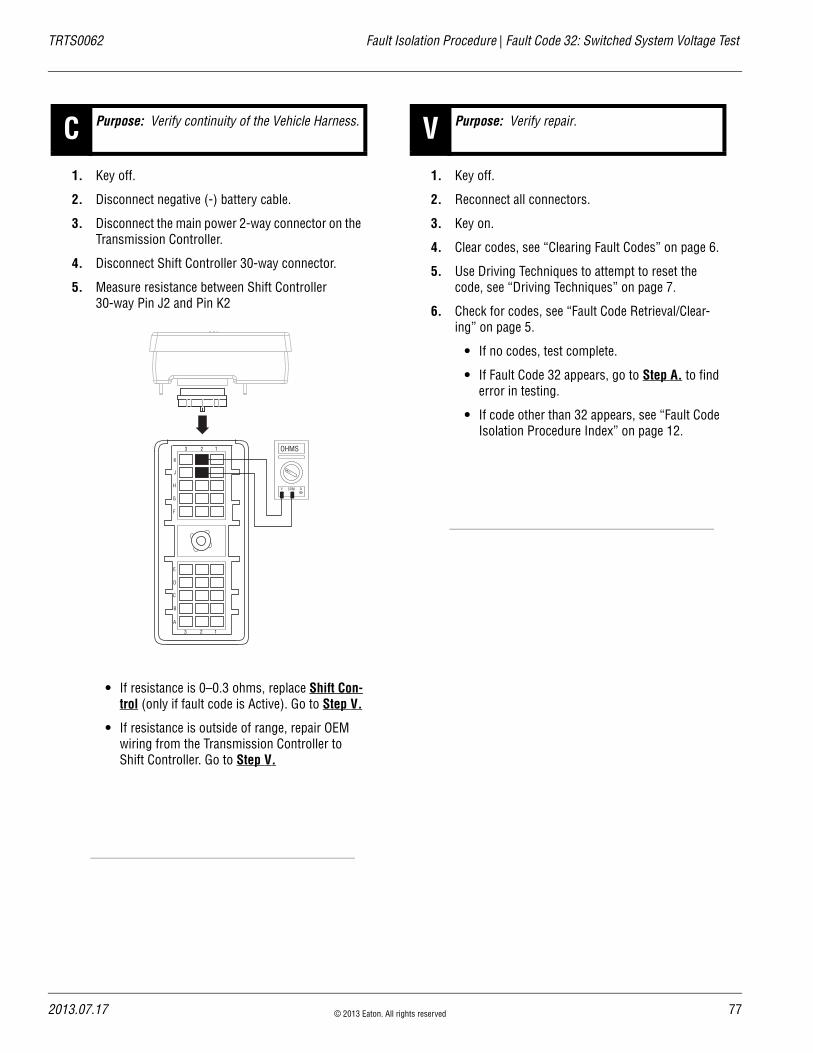
TRTS0062 Fault Isolation Procedure | Fault Code 32: Switched System Voltage Test
1. Key off.
2. Disconnect negative (-) battery cable.
3. Disconnect the main power 2-way connector on the Transmission Controller.
4. Disconnect Shift Controller 30-way connector.
5. Measure resistance between Shift Controller 30-way Pin J2 and Pin K2
• If resistance is 0–0.3 ohms, replace Shift Con-trol (only if fault code is Active). Go to Step V.
• If resistance is outside of range, repair OEM wiring from the Transmission Controller to Shift Controller. Go to Step V.
1. Key off.
2. Reconnect all connectors.
3. Key on.
4. Clear codes, see “Clearing Fault Codes” on page 6.
5. Use Driving Techniques to attempt to reset the code, see “Driving Techniques” on page 7.
6. Check for codes, see “Fault Code Retrieval/Clear-ing” on page 5.
• If no codes, test complete.
• If Fault Code 32 appears, go to Step A. to find error in testing.
• If code other than 32 appears, see “Fault Code Isolation Procedure Index” on page 12.
C Purpose: Verify continuity of the Vehicle Harness.
OHMS
V COM A
K
J
H
G
F
E
D
C
B
A
3 2 1
3 2 1
V Purpose: Verify repair.
2013.07.17 © 2013 Eaton. All rights reserved 77
78
Fault Code 33: Battery Voltage Supply | Fault Isolation Procedure TRTS0062
Fault Code 33: Battery Voltage SupplyJ1587:MID 130 PID 168 FMI 4
OverviewFault Code 33 indicates the battery power supply to the Shift Controller Pin J1 and Pin K1 is below 7 volts.
DetectionThe fault is detected immediately after power up. This fault causes the Service light to flash, but cannot be retrieved via key clicks (because turning the ignition key off at this point results in an immediate shutdown).
Conditions to Set Fault Code Active
FallbackIf this fault occures while moving, it causes a current gear fallback. Once the vehicle is stopped, starting gear and reverse can be engaged
Possible Causes This fault code can be caused by any of the following:
• Battery bus fuse/circuit breaker is open
• Low batteries
• Damaged Vehicle Harness
• Malfunctioning Shift Controller
Additional Tools • Basic hand tools
• Eaton Test Adapter kit
• Digital volt/ohm meter
© 2013 Eaton. All rights reserved 2013.07.17
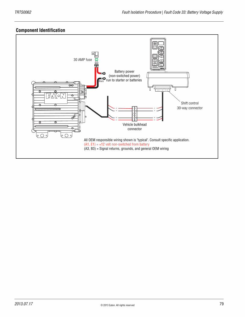
TRTS0062 Fault Isolation Procedure | Fault Code 33: Battery Voltage Supply
Component Identification
Black
30 AMP fuse
Battery power(non-switched power)
run to starter or batteries
All OEM responsible wiring shown is "typical". Consult specific application.(A1, E1) = +12 volt non-switched from battery (A3, B3) = Signal returns, grounds, and general OEM wiring
VOLUMECONTROL
SERVICE
SHIFT
EATON FULLERTRANSMISSIONS
L
H
D
N
R
A1
A3
B3
E1
J1
J3
K3
K1
Vehicle bulkheadconnector
Shift control30-way connector
2013.07.17 © 2013 Eaton. All rights reserved 79

80
Fault Code 33: Battery Voltage Supply Test | Fault Isolation Procedure TRTS0062
Fault Code 33: Battery Voltage Supply Test
1. Key off.
2. Inspect main power 2-way connector terminals, in-line fuse holder and power supply connections for integrity and corrosion.
• If no problem found, go to Step B.
• If a problem is found, repair power/ground path for the main power supply. Go to Step V.
1. Key off.
2. Insert 20-amp fuse into main power 2-way connec-tor.
• If fuse blows immediately, go to Step V.
• If fuse does not blow immediately, repair wir-ing from the battery to the Transmission Con-troller. Go to Step V.
1. Key on.
2. Retrieve codes, see “Retrieving Fault Codes” on page 5.
• If Fault Code 33 is Active, see “Electrical Sys-tem Pretest” on page 15.
• If Fault Code 33 is Inactive, test complete.
APurpose: Measure battery voltage. Visually inspect the batteries, inline fuse and power and ground supplies to the ECU.
A B
+–
+–
+–
+–
B Purpose: Check for proper power supply at main power 2-way connector.
V Purpose: Verify repair.
Main Power Supply 2-Way Connector20 Amp Fuse
30 Amp Fuse
© 2013 Eaton. All rights reserved 2013.07.17

TRTS0062 Fault Isolation Procedure | Fault Code 33: Battery Voltage Supply Test
2013.07.17 © 2013 Eaton. All rights reserved 81

82
Fault Code 35: J1939 Data Link | Fault Isolation Procedure TRTS0062
Fault Code 35: J1939 Data LinkJ1587:MID 130 SID 231 FMI 2
OverviewFault Code 35 indicates the transmission failed to commu-nicate with the engine over the J1939 data link.
DetectionStarting 75 seconds after key on and throughout the opera-tion, the Shift Controller constantly communicates with the engine ECM. If communication fails for more than 5 sec-onds, Fault Code 35 is set.
Conditions to Set Fault Code Active
FallbackIf the fault occurs while moving, it causes a current gear fallback. Once vehicle has stopped, the starting gear and reverse can be engaged. If the failure occurs at system ini-tialization, it causes an AutoSelect fallback mode.
Possible Causes This fault can be caused by any of the following:
• J1939 data link
• Engine ECM
• Vehicle Harness or Connections
• Engine Harness or Connections
• Excessive radio interference
• Shift Controller
Additional Tools • Basic hand tools
• Eaton Test Adapter kit
• Digital volt/ohm meter
© 2013 Eaton. All rights reserved 2013.07.17

TRTS0062 Fault Isolation Procedure | Fault Code 35: J1939 Data Link
Component Identification
Detroit Diesel Cummins Caterpillar
Shift control
Typical J-1939/11 data link harness(OEM supplied)
Shift control30-way connector
MackEngine ECM
BA
C
–J-1939+J-1939
Shield
2013.07.17 © 2013 Eaton. All rights reserved 83

84
Fault Code 35: J1939 Data Link Test | Fault Isolation Procedure TRTS0062
Fault Code 35: J1939 Data Link Test
1. Key off.
2. Disconnect Shift Controller 30-way connector.
3. Disconnect engine ECM connector which contains the J1939 Data Link.
4. Measure resistance between: - Shift Controller 30-way connector Pin G1 and
engine ECM pin (see OEM wiring for positive (+) pin of J1939)
- Shift Controller 30-way Pin G1 and ground
• If resistance between Pin G1 and engine ECM pin (see OEM wiring for positive (+) J1939 pin) is 0–0.3 ohms, and if resistance between Pin G1 and ground is more than 10K ohms or open circuit [OL], go to Step B.
• If resistance is outside of range, repair J1939 Data Link Harness between engine ECM and Shift Controller, go to Step V.
1. Key off.
2. Measure resistance between: - Shift Controller 30-way connector Pin G2 and
engine ECM pin (see OEM wiring for negative (-) pin of J1939)
- Shift Controller 30-way Pin G2 and ground
• If resistance between Pin G2 and engine ECM pin (see OEM wiring for negative (-) pin of J1939) is 0–0.3 ohms, and if resistance between Pin G2 and ground is more than 10K ohms or open circuit [OL] and:
- If equipped with J1939 Lite, go to Step D.- If not equipped with J1939 Lite, go to Step
C.
• If resistance is outside of range, repair J1939 Data Link Harness between engine ECM and Shift Controller, go to Step V.
A Purpose: Verify continuity of the OEM J1939 data high (+) circuit and test for a short to ground.
K
J
H
G
F
E
D
C
B
A
3 2 1
3 2 1
OHMS
V COM A
engine ECM
K
J
H
G
F
E
D
C
B
A
3 2 1
3 2 1
OHMS
V COM A
GROUND
B Purpose: Verify continuity of the OEM J1939 data low (-) circuit and test for a short to ground.
K
J
H
G
F
E
D
C
B
A
3 2 1
3 2 1
OHMS
V COM A
engine ECM
K
J
H
G
F
E
D
C
B
A
3 2 1
3 2 1
OHMS
V COM A
GROUND
© 2013 Eaton. All rights reserved 2013.07.17
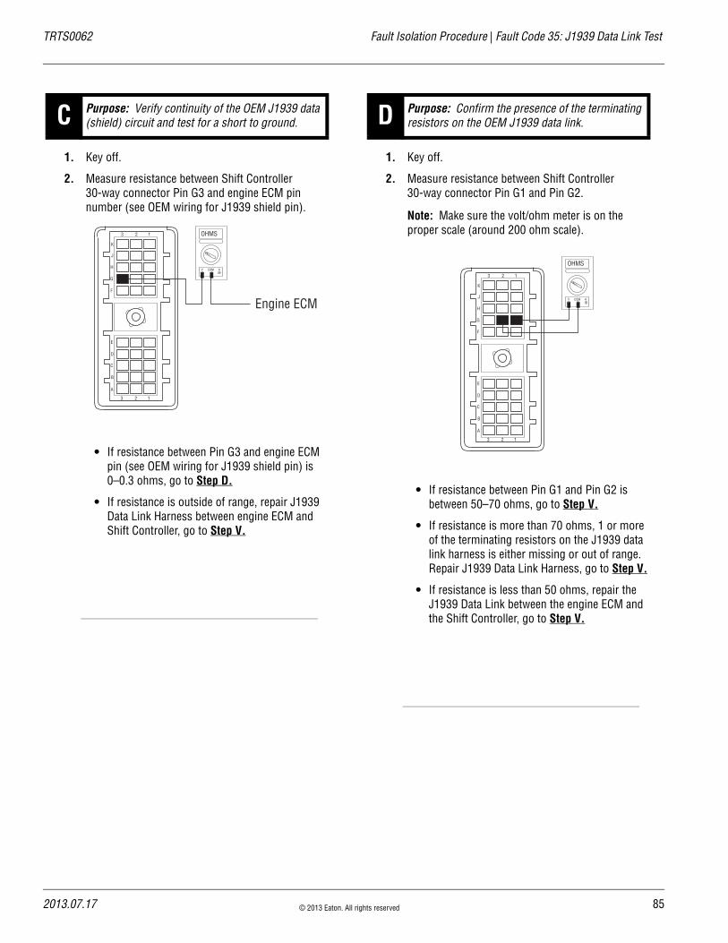
TRTS0062 Fault Isolation Procedure | Fault Code 35: J1939 Data Link Test
1. Key off.
2. Measure resistance between Shift Controller 30-way connector Pin G3 and engine ECM pin number (see OEM wiring for J1939 shield pin).
• If resistance between Pin G3 and engine ECM pin (see OEM wiring for J1939 shield pin) is 0–0.3 ohms, go to Step D.
• If resistance is outside of range, repair J1939 Data Link Harness between engine ECM and Shift Controller, go to Step V.
1. Key off.
2. Measure resistance between Shift Controller 30-way connector Pin G1 and Pin G2.
Note: Make sure the volt/ohm meter is on the proper scale (around 200 ohm scale).
• If resistance between Pin G1 and Pin G2 is between 50–70 ohms, go to Step V.
• If resistance is more than 70 ohms, 1 or more of the terminating resistors on the J1939 data link harness is either missing or out of range. Repair J1939 Data Link Harness, go to Step V.
• If resistance is less than 50 ohms, repair the J1939 Data Link between the engine ECM and the Shift Controller, go to Step V.
C Purpose: Verify continuity of the OEM J1939 data (shield) circuit and test for a short to ground.
K
J
H
G
F
E
D
C
B
A
3 2 1
3 2 1
OHMS
V COM A
Engine ECM
D Purpose: Confirm the presence of the terminating resistors on the OEM J1939 data link.
K
J
H
G
F
E
D
C
B
A
3 2 1
3 2 1
OHMS
V COM A
2013.07.17 © 2013 Eaton. All rights reserved 85

86
Fault Code 35: J1939 Data Link Test | Fault Isolation Procedure TRTS0062
1. Key off.
2. Key on.
3. Clear codes, see “Clearing Fault Codes” on page 6.
4. Use Driving Techniques to attempt to reset the code, see “Driving Techniques” on page 7.
5. Check for codes, see “Retrieving Fault Codes” on page 5.
• If no codes, test complete.
• If Fault Code 35 appears, go to Step A. to find error in testing.
• If code other than 35 appears, see “Fault Code Isolation Procedure Index” on page 12.
V Purpose: Verify repair.
© 2013 Eaton. All rights reserved 2013.07.17
TRTS0062 Fault Isolation Procedure | Fault Code 35: J1939 Data Link Test
2013.07.17 © 2013 Eaton. All rights reserved 87

88
Fault Code 41: Range Failed to Engage | Fault Isolation Procedure TRTS0062
Fault Code 41: Range Failed to EngageJ1587:MID 130 SID 56 FMI 7
OverviewFault Code 41 indicates the transmission is unable to com-plete a shift across the range. The range is either stuck in HI or LO, or cannot complete engagement into HI or LO.
DetectionThe transmission attempts the same range shift 5 consecu-tive times and determines the shift cannot be completed based on the speeds across the back box.
Conditions to Set Fault Code Active
FallbackThis fault causes a 5-speed fallback and the transmission stays in either LO range or HI range. When the vehicle comes to a stop, an attempt to shift into LO range is made.
Possible Causes This fault code can be caused by any of the following:
• Low air pressure
• Contaminated air supply
• Air leak
• Range valve
• Range Synchronizer
• Range Actuator, Cylinder, Piston or Yoke
Additional Tools • Basic hand tools
• Two 0-100 PSI Air Pressure gauges
© 2013 Eaton. All rights reserved 2013.07.17

TRTS0062 Fault Isolation Procedure | Fault Code 41: Range Failed to Engage
Component Identification
Range system
HI diagnostic port
LO diagnostic port (on opposite side of HI diagnostic port, out of view)
2013.07.17 © 2013 Eaton. All rights reserved 89

90
Fault Code 41: Range Failed to Engage Test | Fault Isolation Procedure TRTS0062
Fault Code 41: Range Failed to Engage Test
1. Key off.
2. Install both 0-100 PSI air pressure gauges into the range cover diagnostic ports.
3. Start engine and allow air pressure to build to gov-ernor cut off.
4. Release clutch to register Input Shaft speed in the transmission.
5. Turn off engine, but leave key on.
6. Select reverse with Shift Controller, then select neutral.
• If LO range air pressure gauge is between 55–65 PSI, and the HI range air pressure gauge is at 0 PSI, go to Step B.
• If neither air pressure gauge reads as listed above, replace Range Valve and Range Cylin-der Cover as required. Go to Step V.
1. Key on.
2. With Shift Controller, select reverse, press the up-shift button, then select neutral.
Note: If the Gear Display does not read “H” (10-speed) or “IH” (18-speed), go to the Up-Down Button Test.
• If HI range air pressure gauge is between 55–65 PSI and LO air pressure gauge is at 0 PSI, repair range system as required. Go to Step V.
• If neither air pressure gauge reads as listed above, replace Range Valve and Range Cylin-der Cover as required. Go to Step V.
A Purpose: Measure LO range air pressure.
LO range0-100 PSI gauge
HI range0-100 PSI gauge
B Purpose: Measure HI range air pressure.
10-Speed 18-Speed
or
LO range0-100 PSI gauge
HI range0-100 PSI gauge
© 2013 Eaton. All rights reserved 2013.07.17

TRTS0062 Fault Isolation Procedure | Fault Code 41: Range Failed to Engage Test
1. Key off.
2. Remove all gauges.
3. Key on.
4. Clear codes, see “Clearing Fault Codes” on page 6.
5. Use Driving Techniques to attempt to reset the code, see “Driving Techniques” on page 7.
6. Check for codes, see “Retrieving Fault Codes” on page 5.
• If no codes, test complete.
• If Fault Code 41 appears, go to Step A. to find error in testing.
• If a code other than 41 appears, see “Fault Code Isolation Procedure Index” on page 12.
V Purpose: Verify repair.
2013.07.17 © 2013 Eaton. All rights reserved 91

92
Fault Code 42: Splitter Failed to Engage | Fault Isolation Procedure TRTS0062
Fault Code 42: Splitter Failed to EngageJ1587:MID 130 SID 61 FMI 7
OverviewFault Code 42 indicates the transmission is unable to com-plete a shift across the Splitter. The Splitter is either stuck in HI or LO, or cannot complete engagement into HI or LO.
DetectionThe transmission attempts the same splitter shift 5 consec-utive times and determines the shift cannot be completed based on the speeds across the back box.
Conditions to Set Fault Code Active
FallbackThis fault causes a 9-speed fallback and the transmission stays in either LO split or HI split.
Possible Causes This fault code can be caused by any of the following:
• Low air pressure
• Contaminated air supply
• Air leak
• Splitter valve
• Splitter Actuator, Cylinder, Piston or Yoke
Additional Tools • Basic hand tools
• Two 0-100 PSI Air Pressure gauges
© 2013 Eaton. All rights reserved 2013.07.17

TRTS0062 Fault Isolation Procedure | Fault Code 42: Splitter Failed to Engage
Component Identification
Splitter system
HI diagnostic portLO diagnostic port
2013.07.17 © 2013 Eaton. All rights reserved 93
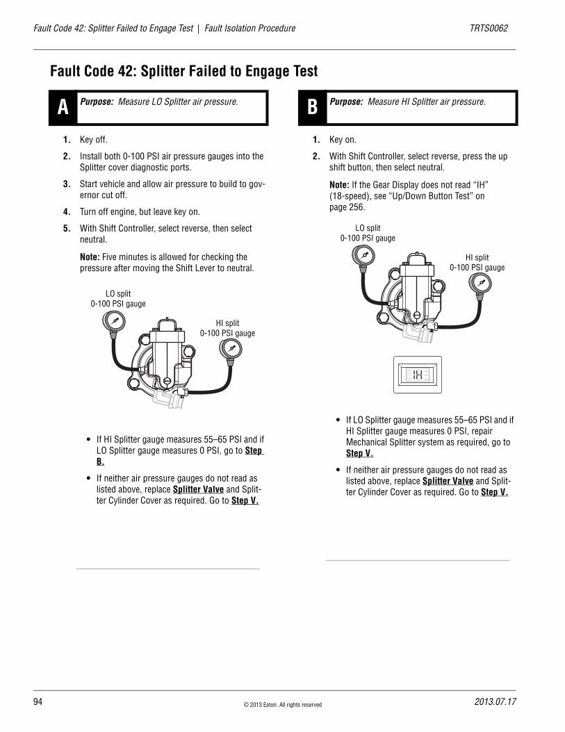
94
Fault Code 42: Splitter Failed to Engage Test | Fault Isolation Procedure TRTS0062
Fault Code 42: Splitter Failed to Engage Test
1. Key off.
2. Install both 0-100 PSI air pressure gauges into the Splitter cover diagnostic ports.
3. Start vehicle and allow air pressure to build to gov-ernor cut off.
4. Turn off engine, but leave key on.
5. With Shift Controller, select reverse, then select neutral.
Note: Five minutes is allowed for checking the pressure after moving the Shift Lever to neutral.
• If HI Splitter gauge measures 55–65 PSI and if LO Splitter gauge measures 0 PSI, go to Step B.
• If neither air pressure gauges do not read as listed above, replace Splitter Valve and Split-ter Cylinder Cover as required. Go to Step V.
1. Key on.
2. With Shift Controller, select reverse, press the up shift button, then select neutral.
Note: If the Gear Display does not read “IH” (18-speed), see “Up/Down Button Test” on page 256.
• If LO Splitter gauge measures 55–65 PSI and if HI Splitter gauge measures 0 PSI, repair Mechanical Splitter system as required, go to Step V.
• If neither air pressure gauges do not read as listed above, replace Splitter Valve and Split-ter Cylinder Cover as required. Go to Step V.
A Purpose: Measure LO Splitter air pressure.
LO split0-100 PSI gauge
HI split0-100 PSI gauge
B Purpose: Measure HI Splitter air pressure.
LO split0-100 PSI gauge
HI split0-100 PSI gauge
© 2013 Eaton. All rights reserved 2013.07.17

TRTS0062 Fault Isolation Procedure | Fault Code 42: Splitter Failed to Engage Test
1. Key off.
2. Remove all air pressure gauges.
3. Key on.
4. Clear codes, see “Clearing Fault Codes” on page 6.
5. Use Driving Techniques to attempt to reset the code, see “Driving Techniques” on page 7.
6. Check for codes, see “Retrieving Fault Codes” on page 5.
• If no codes, test complete.
• If Fault Code 42 appears, go to Step A. to find error in testing.
• If code other than 42 appears, see “Fault Code Isolation Procedure Index” on page 12.
V Purpose: Verify repair.
2013.07.17 © 2013 Eaton. All rights reserved 95

96
Fault Code 43: Range Valve | Fault Isolation Procedure TRTS0062
Fault Code 43: Range ValveJ1587:MID 130 SID 35, 36 FMI 3, 4, 5
OverviewFault Code 43 indicates an electrical failure of the solenoids that control the range shift.
DetectionStarting at key on and throughout operation, the Transmis-sion Controller constantly measures this Range Valve cir-cuit. A failure of short to battery, short to ground or open circuit is detected.
Conditions to Set Fault Code Active
FallbackThis fault causes a 5-speed fallback and the transmission stays in either low range or high range. When the vehicle comes to a stop, an attempt to shift into low range is made.
Possible Causes This fault code can be caused by any of the following:
• Range Valve
• Transmission Harness
• Transmission Controller
Additional Tools • Basic hand tools
• Eaton Test Adapter kit
• Digital volt/ohm meter
© 2013 Eaton. All rights reserved 2013.07.17
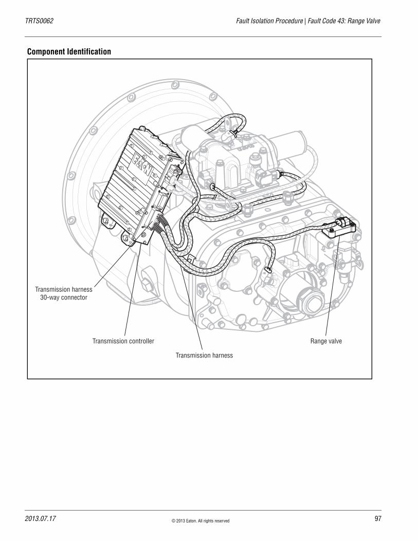
TRTS0062 Fault Isolation Procedure | Fault Code 43: Range Valve
Component Identification
Transmission controller Range valve
Transmission harness
Transmission harness30-way connector
2013.07.17 © 2013 Eaton. All rights reserved 97
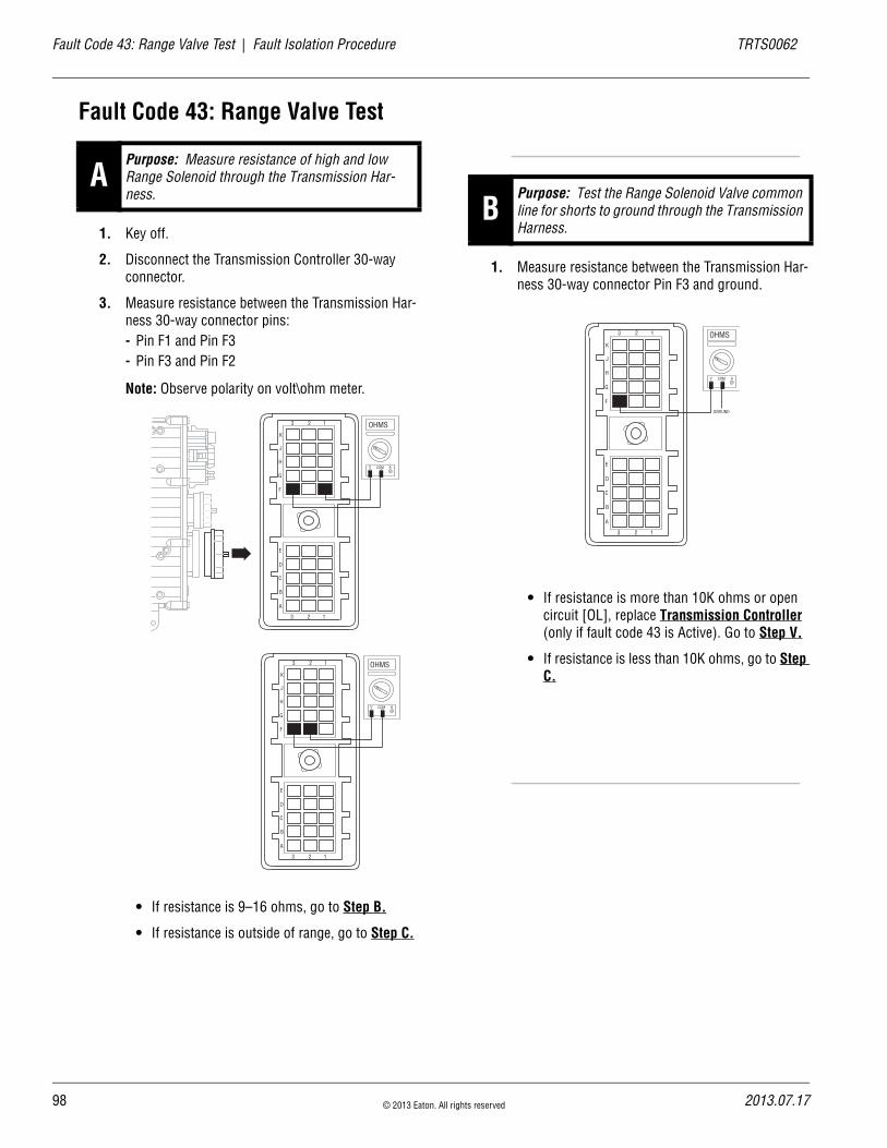
98
Fault Code 43: Range Valve Test | Fault Isolation Procedure TRTS0062
Fault Code 43: Range Valve Test
1. Key off.
2. Disconnect the Transmission Controller 30-way connector.
3. Measure resistance between the Transmission Har-ness 30-way connector pins:- Pin F1 and Pin F3- Pin F3 and Pin F2
Note: Observe polarity on volt\ohm meter.
• If resistance is 9–16 ohms, go to Step B.
• If resistance is outside of range, go to Step C.
1. Measure resistance between the Transmission Har-ness 30-way connector Pin F3 and ground.
• If resistance is more than 10K ohms or open circuit [OL], replace Transmission Controller (only if fault code 43 is Active). Go to Step V.
• If resistance is less than 10K ohms, go to Step C.
APurpose: Measure resistance of high and low Range Solenoid through the Transmission Har-ness.
OHMS
V COM A
K
J
H
G
F
E
D
C
B
A
3 2 1
3 2 1
OHMS
V COM A
K
J
H
G
F
E
D
C
B
A
3 2 1
3 2 1
BPurpose: Test the Range Solenoid Valve common line for shorts to ground through the Transmission Harness.
OHMS
V COM A
K
J
H
G
F
E
D
C
B
A
3 2 1
3 2 1
GROUND
© 2013 Eaton. All rights reserved 2013.07.17
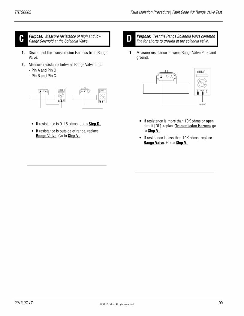
TRTS0062 Fault Isolation Procedure | Fault Code 43: Range Valve Test
1. Disconnect the Transmission Harness from Range Valve.
2. Measure resistance between Range Valve pins:- Pin A and Pin C- Pin B and Pin C
• If resistance is 9–16 ohms, go to Step D.
• If resistance is outside of range, replace Range Valve. Go to Step V.
1. Measure resistance between Range Valve Pin C and ground.
• If resistance is more than 10K ohms or open circuit [OL], replace Transmission Harness go to Step V.
• If resistance is less than 10K ohms, replace Range Valve. Go to Step V.
C Purpose: Measure resistance of high and low Range Solenoid at the Solenoid Valve.
BC A OHMS
V COM A
BC A OHMS
V COM A
D Purpose: Test the Range Solenoid Valve common line for shorts to ground at the solenoid valve.
BC A
GROUND
OHMS
V COM A
2013.07.17 © 2013 Eaton. All rights reserved 99

10
Fault Code 43: Range Valve Test | Fault Isolation Procedure TRTS0062
1. Key off.
2. Reconnect all connectors.
3. Key on.
4. Clear codes, see “Clearing Fault Codes” on page 6.
5. Use Driving Techniques to attempt to reset the code, see “Driving Techniques” on page 7.
6. Check for codes, see “Retrieving Fault Codes” on page 5.
• If no codes, test complete.
• If Fault Code 43 appears, go to Step A. to find error in testing.
• If code other than 43 appears, see “Fault Code Isolation Procedure Index” on page 12.
V Purpose: Verify repair.
0 © 2013 Eaton. All rights reserved 2013.07.17

TRTS0062 Fault Isolation Procedure | Fault Code 43: Range Valve Test
2013.07.17 © 2013 Eaton. All rights reserved 101

10
Fault Code 44: Inertia Brake Solenoid Coil | Fault Isolation Procedure TRTS0062
Fault Code 44: Inertia Brake Solenoid CoilJ1587:MID 130 PID 53 FMI 3, 4, 5
OverviewFault Code 44 indicates an electrical failure of the solenoid that controls the pneumatic Inertia Brake.
DetectionStarting at key on and throughout operation, the Transmis-sion Controller constantly measures this circuit. A failure mode of a short to battery, short to ground, or open circuit is detected.
Conditions to Set Fault Code Active
FallbackThere is no fallback associated with this failure; however, it may be difficult to perform an initial engagement due to a poorly adjusted clutch. Also, hill shifting performance may be reduced.
Possible Causes This fault code can be caused by any of the following:
• Inertia Brake Solenoid
• Transmission Harness
• Transmission Controller
Additional Tools • Basic hand tools
• Eaton Test Adapter kit
• Digital volt/ohm meter
2 © 2013 Eaton. All rights reserved 2013.07.17
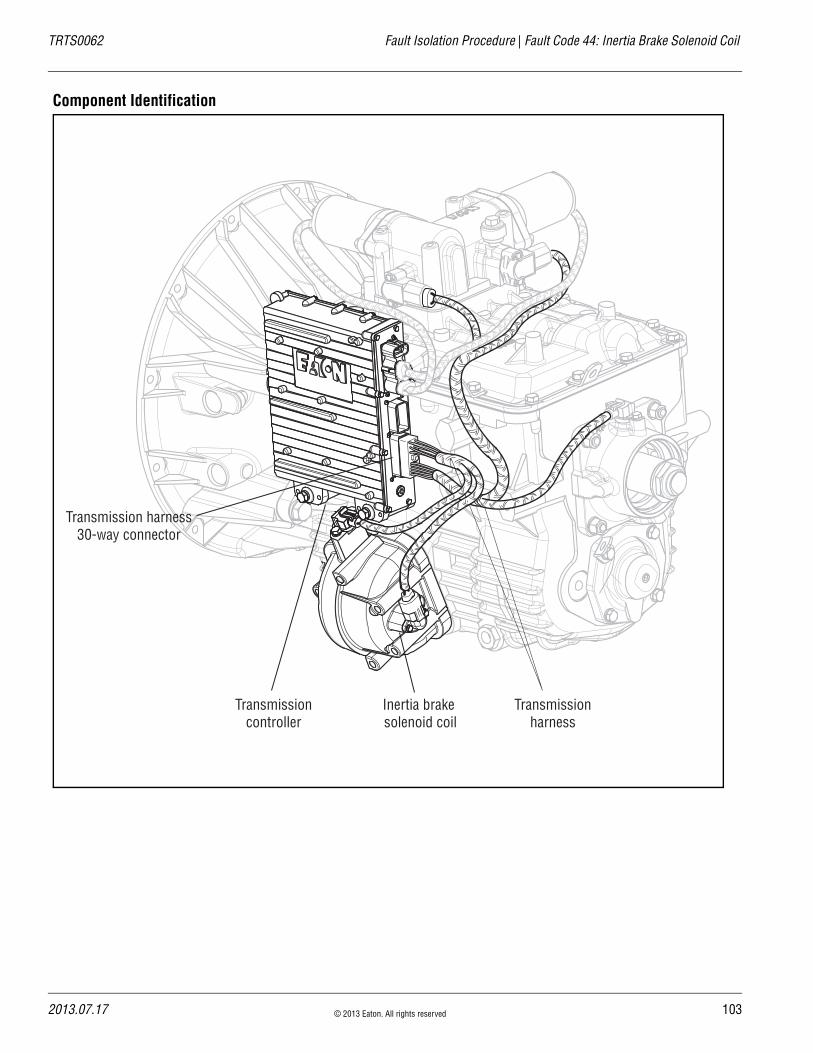
TRTS0062 Fault Isolation Procedure | Fault Code 44: Inertia Brake Solenoid Coil
Component Identification
Transmissioncontroller
Transmissionharness
Inertia brake solenoid coil
Transmission harness30-way connector
2013.07.17 © 2013 Eaton. All rights reserved 103
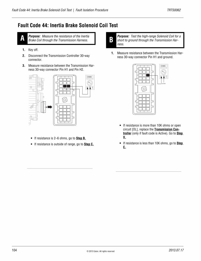
10
Fault Code 44: Inertia Brake Solenoid Coil Test | Fault Isolation Procedure TRTS0062
Fault Code 44: Inertia Brake Solenoid Coil Test
1. Key off.
2. Disconnect the Transmission Controller 30-way connector.
3. Measure resistance between the Transmission Har-ness 30-way connector Pin H1 and Pin H2.
• If resistance is 2–6 ohms, go to Step B.
• If resistance is outside of range, go to Step C.
1. Measure resistance between the Transmission Har-ness 30-way connector Pin H1 and ground.
• If resistance is more than 10K ohms or open circuit [OL], replace the Transmission Con-troller (only if fault code is Active). Go to Step V.
• If resistance is less than 10K ohms, go to Step C.
A Purpose: Measure the resistance of the Inertia Brake Coil through the Transmission Harness.
OHMS
V COM A
K
J
H
G
F
E
D
C
B
A
3 2 1
3 2 1
BPurpose: Test the high-range Solenoid Coil for a short to ground through the Transmission Har-ness.
GROUND
OHMS
V COM A
K
J
H
G
F
E
D
C
B
A
3 2 1
3 2 1
4 © 2013 Eaton. All rights reserved 2013.07.17
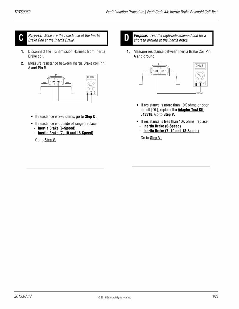
TRTS0062 Fault Isolation Procedure | Fault Code 44: Inertia Brake Solenoid Coil Test
1. Disconnect the Transmission Harness from Inertia Brake coil.
2. Measure resistance between Inertia Brake coil Pin A and Pin B.
• If resistance is 2–6 ohms, go to Step D.
• If resistance is outside of range, replace:- Inertia Brake (6-Speed)- Inertia Brake (7, 10 and 18-Speed)
Go to Step V.
1. Measure resistance between Inertia Brake Coil Pin A and ground.
• If resistance is more than 10K ohms or open circuit [OL], replace the Adapter Test Kit J43318. Go to Step V.
• If resistance is less than 10K ohms, replace:- Inertia Brake (6-Speed)- Inertia Brake (7, 10 and 18-Speed)
Go to Step V.
C Purpose: Measure the resistance of the Inertia Brake Coil at the Inertia Brake.
OHMS
V COM A
BA
D Purpose: Test the high-side solenoid coil for a short to ground at the inertia brake.
GROUND
OHMS
V COM A
BA
2013.07.17 © 2013 Eaton. All rights reserved 105
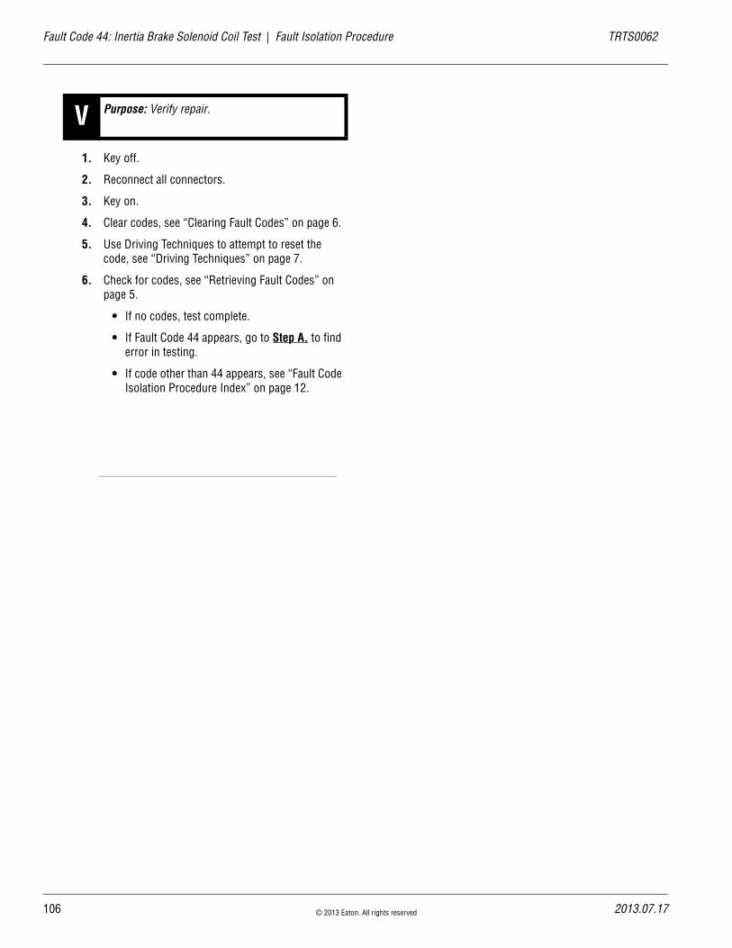
10
Fault Code 44: Inertia Brake Solenoid Coil Test | Fault Isolation Procedure TRTS0062
1. Key off.
2. Reconnect all connectors.
3. Key on.
4. Clear codes, see “Clearing Fault Codes” on page 6.
5. Use Driving Techniques to attempt to reset the code, see “Driving Techniques” on page 7.
6. Check for codes, see “Retrieving Fault Codes” on page 5.
• If no codes, test complete.
• If Fault Code 44 appears, go to Step A. to find error in testing.
• If code other than 44 appears, see “Fault Code Isolation Procedure Index” on page 12.
V Purpose: Verify repair.
6 © 2013 Eaton. All rights reserved 2013.07.17
TRTS0062 Fault Isolation Procedure | Fault Code 44: Inertia Brake Solenoid Coil Test
2013.07.17 © 2013 Eaton. All rights reserved 107

10
Fault Code 46: Splitter Valve | Fault Isolation Procedure TRTS0062
Fault Code 46: Splitter ValveJ1587:MID 130 SID 37, 38 FMI 3, 4, 5
OverviewFault Code 46 indicates an electrical failure of the solenoids that control the Splitter.
DetectionStarting at key on and throughout operation, the Transmis-sion Controller constantly measures this circuit. Depending on the reading, a failure mode of short to battery, short to ground, or open circuit is detected.
Conditions to Set Fault Code Active
FallbackThis fault causes a 9-speed fallback and the transmission stays in either a low split or high split.
Possible Causes This fault code can be caused by any of the following:
• Splitter Valve
• Transmission Harness
• Transmission Controller
Additional Tools • Basic hand tools
• Eaton Test Adapter kit
• Digital volt/ohm meter
8 © 2013 Eaton. All rights reserved 2013.07.17
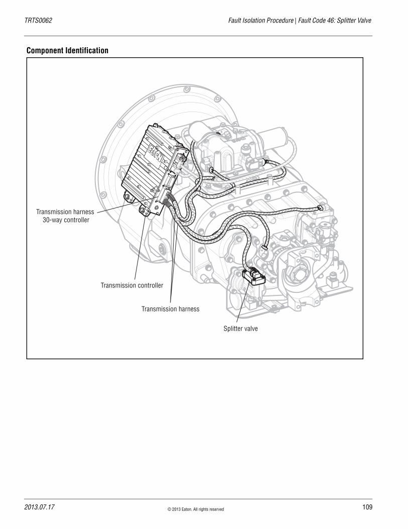
TRTS0062 Fault Isolation Procedure | Fault Code 46: Splitter Valve
Component Identification
Transmission controller
Splitter valve
Transmission harness
Transmission harness 30-way controller
2013.07.17 © 2013 Eaton. All rights reserved 109
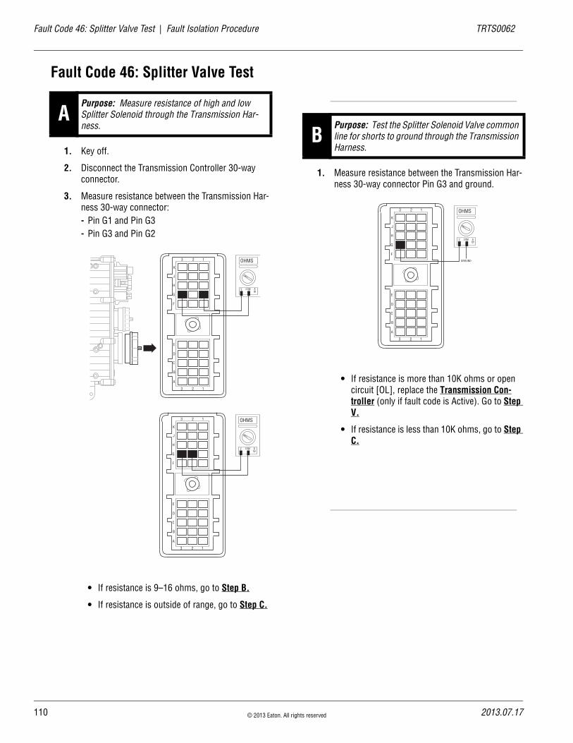
11
Fault Code 46: Splitter Valve Test | Fault Isolation Procedure TRTS0062
Fault Code 46: Splitter Valve Test
1. Key off.
2. Disconnect the Transmission Controller 30-way connector.
3. Measure resistance between the Transmission Har-ness 30-way connector:- Pin G1 and Pin G3- Pin G3 and Pin G2
• If resistance is 9–16 ohms, go to Step B.
• If resistance is outside of range, go to Step C.
1. Measure resistance between the Transmission Har-ness 30-way connector Pin G3 and ground.
• If resistance is more than 10K ohms or open circuit [OL], replace the Transmission Con-troller (only if fault code is Active). Go to Step V.
• If resistance is less than 10K ohms, go to Step C.
APurpose: Measure resistance of high and low Splitter Solenoid through the Transmission Har-ness.
OHMS
V COM A
K
J
H
G
F
E
D
C
B
A
3 2 1
3 2 1
OHMS
V COM A
K
J
H
G
F
E
D
C
B
A
3 2 1
3 2 1
BPurpose: Test the Splitter Solenoid Valve common line for shorts to ground through the Transmission Harness.
OHMS
V COM A
K
J
H
G
F
E
D
C
B
A
3 2 1
3 2 1
GROUND
0 © 2013 Eaton. All rights reserved 2013.07.17
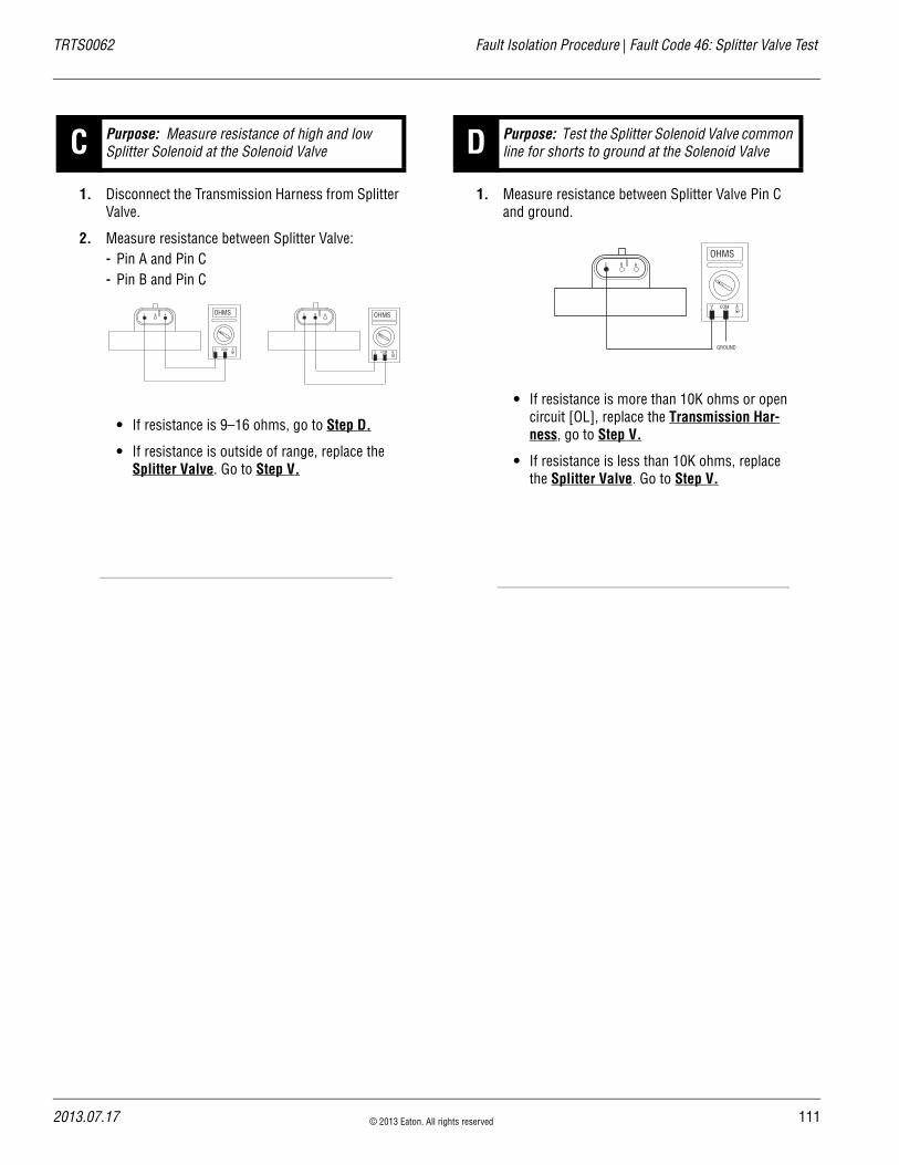
TRTS0062 Fault Isolation Procedure | Fault Code 46: Splitter Valve Test
1. Disconnect the Transmission Harness from Splitter Valve.
2. Measure resistance between Splitter Valve:- Pin A and Pin C- Pin B and Pin C
• If resistance is 9–16 ohms, go to Step D.
• If resistance is outside of range, replace the Splitter Valve. Go to Step V.
1. Measure resistance between Splitter Valve Pin C and ground.
• If resistance is more than 10K ohms or open circuit [OL], replace the Transmission Har-ness, go to Step V.
• If resistance is less than 10K ohms, replace the Splitter Valve. Go to Step V.
C Purpose: Measure resistance of high and low Splitter Solenoid at the Solenoid Valve
BC A OHMS
V COM A
BC A OHMS
V COM A
D Purpose: Test the Splitter Solenoid Valve common line for shorts to ground at the Solenoid Valve
BC A
GROUND
OHMS
V COM A
2013.07.17 © 2013 Eaton. All rights reserved 111
11
Fault Code 46: Splitter Valve Test | Fault Isolation Procedure TRTS0062
1. Key off.
2. Reconnect all connectors.
3. Key on.
4. Clear codes, see “Clearing Fault Codes” on page 6.
5. Use Driving Techniques to attempt to reset the code, see “Driving Techniques” on page 7.
6. Check for codes, see “Retrieving Fault Codes” on page 5.
• If no codes, test complete.
• If Fault Code 46 appears, go to Step A. to find error in testing.
• If code other than 46 appears, see “Fault Code Isolation Procedure Index” on page 12.
V Purpose: Verify repair.
2 © 2013 Eaton. All rights reserved 2013.07.17

TRTS0062 Fault Isolation Procedure | Fault Code 46: Splitter Valve Test
2013.07.17 © 2013 Eaton. All rights reserved 113

11
Fault Code 51: Rail Select Sensor | Fault Isolation Procedure TRTS0062
Fault Code 51: Rail Select SensorJ1587:MID 130
OverviewFault Code 51 indicates an electrical failure of the Rail Select Sensor on the Electric Shifter.
DetectionStarting at key on and throughout operation, the Transmis-sion Controller constantly monitors the feedback from the sensor. If the feedback is below 10% or above 90% of the full value of the sensor, the fault code is set. This type of failure represents a short to ground or battery. The Trans-mission Controller also monitors the sensor feedback for a 0 value, indicating an open circuit.
Conditions to Set Fault Code Active
FallbackThis fault causes an in-place fallback.
Possible Causes This fault code can be caused by any of the following:
• Transmission Harness
• Rail Select Sensor
• Transmission Controller
Additional Tools • Basic hand tools
• Eaton Test Adapter kit
• Digital volt/ohm meter
4 © 2013 Eaton. All rights reserved 2013.07.17

TRTS0062 Fault Isolation Procedure | Fault Code 51: Rail Select Sensor
Component Identification
Transmission controller
Rail select sensor
Transmission harness
Transmission harness30-way connector
2013.07.17 © 2013 Eaton. All rights reserved 115
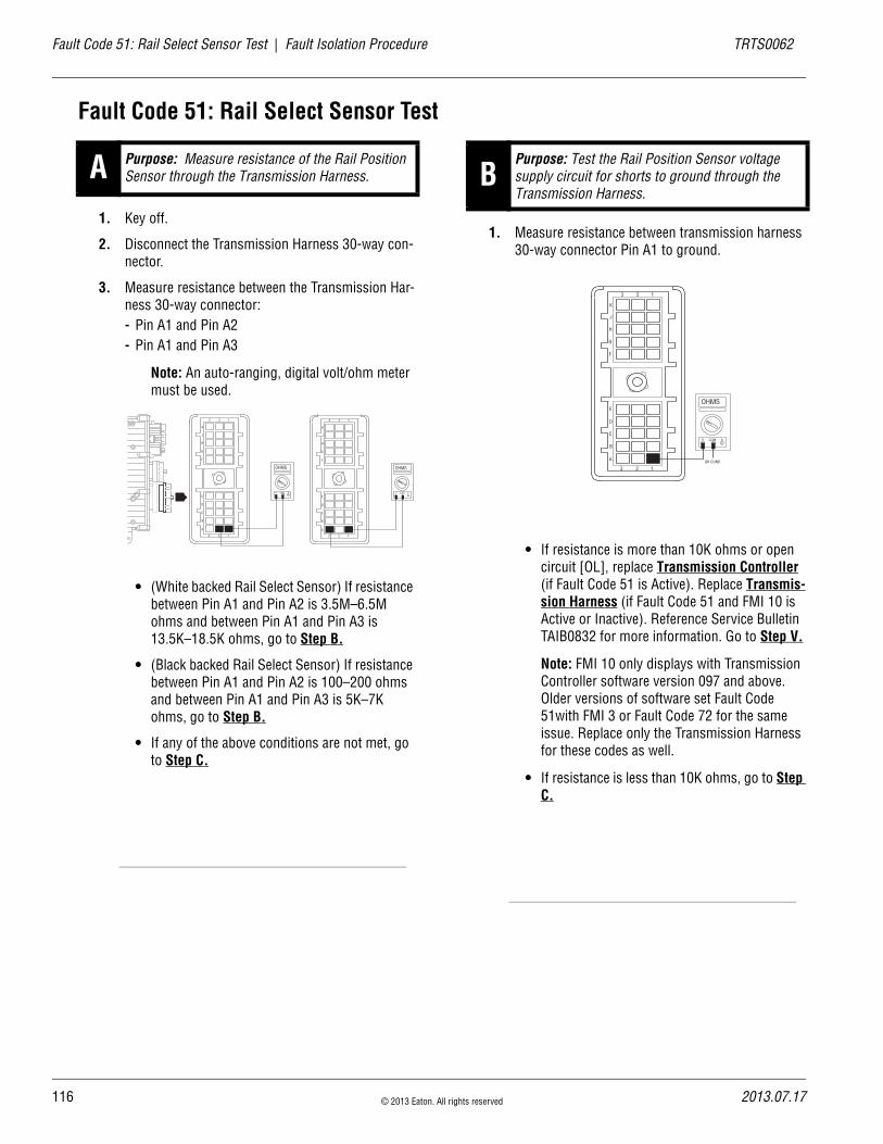
11
Fault Code 51: Rail Select Sensor Test | Fault Isolation Procedure TRTS0062
Fault Code 51: Rail Select Sensor Test
1. Key off.
2. Disconnect the Transmission Harness 30-way con-nector.
3. Measure resistance between the Transmission Har-ness 30-way connector:- Pin A1 and Pin A2- Pin A1 and Pin A3
Note: An auto-ranging, digital volt/ohm meter must be used.
• (White backed Rail Select Sensor) If resistance between Pin A1 and Pin A2 is 3.5M–6.5M ohms and between Pin A1 and Pin A3 is 13.5K–18.5K ohms, go to Step B.
• (Black backed Rail Select Sensor) If resistance between Pin A1 and Pin A2 is 100–200 ohms and between Pin A1 and Pin A3 is 5K–7K ohms, go to Step B.
• If any of the above conditions are not met, go to Step C.
1. Measure resistance between transmission harness 30-way connector Pin A1 to ground.
• If resistance is more than 10K ohms or open circuit [OL], replace Transmission Controller (if Fault Code 51 is Active). Replace Transmis-sion Harness (if Fault Code 51 and FMI 10 is Active or Inactive). Reference Service Bulletin TAIB0832 for more information. Go to Step V.
Note: FMI 10 only displays with Transmission Controller software version 097 and above. Older versions of software set Fault Code 51with FMI 3 or Fault Code 72 for the same issue. Replace only the Transmission Harness for these codes as well.
• If resistance is less than 10K ohms, go to Step C.
A Purpose: Measure resistance of the Rail Position Sensor through the Transmission Harness.
OHMS
V COM A
K
J
H
G
F
E
D
C
B
A
3 2 1
3 2 1
OHMS
V COM A
K
J
H
G
F
E
D
C
B
A
3 2 1
3 2 1
BPurpose: Test the Rail Position Sensor voltage supply circuit for shorts to ground through the Transmission Harness.
OHMS
V COM A
K
J
H
G
F
E
D
C
B
A
3 2 1
3 2 1GR OUND
6 © 2013 Eaton. All rights reserved 2013.07.17
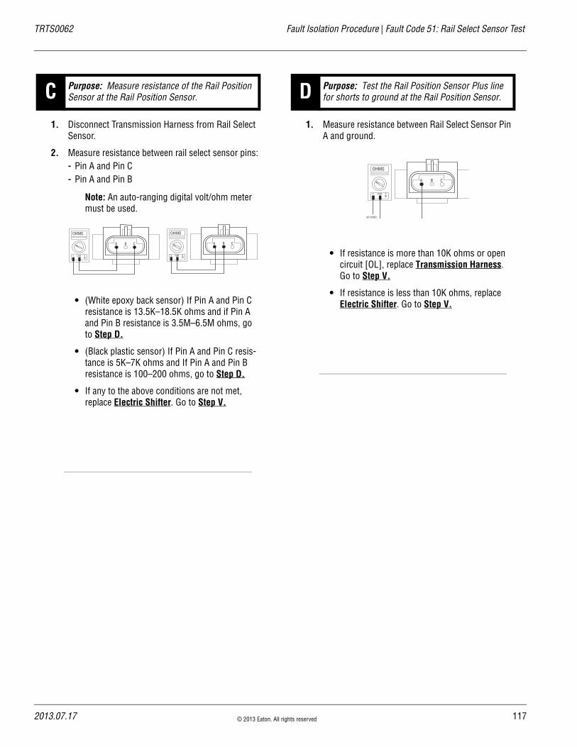
TRTS0062 Fault Isolation Procedure | Fault Code 51: Rail Select Sensor Test
1. Disconnect Transmission Harness from Rail Select Sensor.
2. Measure resistance between rail select sensor pins:- Pin A and Pin C- Pin A and Pin B
Note: An auto-ranging digital volt/ohm meter must be used.
• (White epoxy back sensor) If Pin A and Pin C resistance is 13.5K–18.5K ohms and if Pin A and Pin B resistance is 3.5M–6.5M ohms, go to Step D.
• (Black plastic sensor) If Pin A and Pin C resis-tance is 5K–7K ohms and If Pin A and Pin B resistance is 100–200 ohms, go to Step D.
• If any to the above conditions are not met, replace Electric Shifter. Go to Step V.
1. Measure resistance between Rail Select Sensor Pin A and ground.
• If resistance is more than 10K ohms or open circuit [OL], replace Transmission Harness. Go to Step V.
• If resistance is less than 10K ohms, replace Electric Shifter. Go to Step V.
C Purpose: Measure resistance of the Rail Position Sensor at the Rail Position Sensor.
OHMS
V COM A
BA C
OHMS
V COM A
BA C
D Purpose: Test the Rail Position Sensor Plus line for shorts to ground at the Rail Position Sensor.
GR OUND
OHMS
V COM A
BA C
2013.07.17 © 2013 Eaton. All rights reserved 117

11
Fault Code 51: Rail Select Sensor Test | Fault Isolation Procedure TRTS0062
1. Key off.
2. Reconnect all connectors.
3. Key on.
4. Clear codes, see “Clearing Fault Codes” on page 6.
5. Use Driving Techniques to attempt to reset the code, see “Driving Techniques” on page 7.
6. Check for codes, see “Retrieving Fault Codes” on page 5.
• If no codes, test complete.
• If Fault Code 51 appears, go to Step A. to find error in testing.
• If code other than 51 appears, see “Fault Code Isolation Procedure Index” on page 12.
V Purpose: Verify repair.
8 © 2013 Eaton. All rights reserved 2013.07.17

TRTS0062 Fault Isolation Procedure | Fault Code 51: Rail Select Sensor Test
2013.07.17 © 2013 Eaton. All rights reserved 119

12
Fault Code 52: Gear Select Sensor | Fault Isolation Procedure TRTS0062
Fault Code 52: Gear Select SensorJ1587:MID 130 PID 59 FMI 2, 3, 4
OverviewFault Code 52 indicates an electrical failure of the Gear Select Sensor on the Electric Shifter.
DetectionStarting at key on and throughout operation, the Transmis-sion Controller constantly monitors the feedback from the sensor. If the feedback is below 10% or above 90% of the full value of the sensor, the fault code is set. This type of failure represents a short to ground or to battery voltage. The Transmission Controller also monitors the sensor feed-back for a 0 value, indicating an open circuit.
Conditions to Set Fault Code Active
FallbackThis fault causes an in-place fallback.
Possible Causes This fault code can be caused by any of the following:
• Transmission Harness
• Gear Select Sensor
• Transmission Controller
Additional Tools • Basic hand tools
• Eaton Test Adapter kit
• Digital volt/ohm meter
0 © 2013 Eaton. All rights reserved 2013.07.17
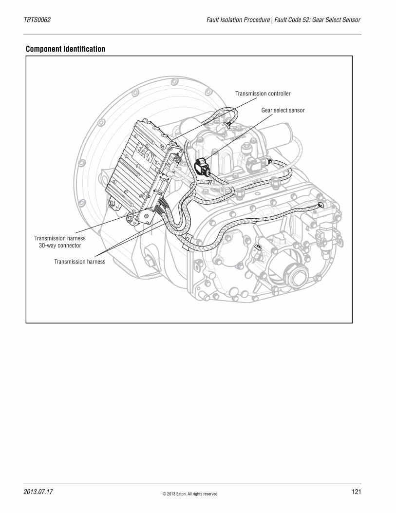
TRTS0062 Fault Isolation Procedure | Fault Code 52: Gear Select Sensor
Component Identification
Transmission controller
Gear select sensor
Transmission harness
Transmission harness30-way connector
2013.07.17 © 2013 Eaton. All rights reserved 121

12
Fault Code 52: Gear Select Sensor Test | Fault Isolation Procedure TRTS0062
Fault Code 52: Gear Select Sensor Test
1. Key off.
2. Disconnect the Transmission controller 30-way connector.
3. Measure resistance between the Transmission Har-ness 30-way connector pins:- Pin B1 and Pin B2- Pin B1 and Pin B3
Note: An auto ranging digital volt/ohm meter must be used.
• (White epoxy back sensor) If Pin B1 and Pin B2 resistance is 3.5M–6.5M ohms and if Pin B1 and Pin B3 resistance is 13.5K–18.5K ohms, go to Step B.
• (Black plastic back sensor) If Pin B1 and Pin B2 resistance is 100–200 ohms and if Pin B1 and Pin B3 resistance is 5K–7K ohms, go to Step B.
• If any of the above conditions are not met, go to Step C.
1. Measure resistance between transmission harness 30-way connector Pin B1 to ground.
• If resistance is more than 10K ohms or open circuit [OL], replace Transmission Controller (only if fault code is Active). Go to Step V.
• If resistance is less than 10K ohms, go to Step C.
A Purpose: Measure resistance of the Gear Position Sensor through the Transmission Harness.
OHMS
V COM A
K
J
H
G
F
E
D
C
B
A
3 2 1
3 1
OHMS
V COM A
K
J
H
G
F
E
D
C
B
A
3 2 1
3 2 12
BPurpose: Test the Gear Position Sensor Plus line for shorts to ground through the Transmission Harness.
OHMS
V COM A
K
J
H
G
F
E
D
C
B
A
3 2 1
3 2 1
GR OUND
2 © 2013 Eaton. All rights reserved 2013.07.17

TRTS0062 Fault Isolation Procedure | Fault Code 52: Gear Select Sensor Test
1. Disconnect transmission harness form Gear Select Sensor.
2. Measure resistance between gear select sensor pins:- Pin A and Pin C- Pin A and Pin B
Note: An auto ranging digital volt/ohm meter must be used.
• (White epoxy back sensor) If Pin A and Pin C resistance is 13.5K–18.5K ohms and if Pin A and Pin B resistance is 3.5M–6.5M ohms, go to Step D.
• (Black plastic back sensor) If Pin A and Pin C resistance is 5K–7K and if Pin A and Pin B resistance is 100–200 ohms, go to Step D.
• If any to the above conditions are not met, replace the Electric Shifter. Go to Step V..
1. Measure resistance between gear select sensor Pin A and ground.
• If resistance is more than 10K ohms or open circuit [OL], replace the Transmission Har-ness. Go to Step V.
• If resistance is less than 10K ohms, replace the Electric Shifter. Go to Step V.
1. Key off.
2. Reconnect all connectors.
3. Key on.
4. Clear codes, see “Clearing Fault Codes” on page 6..
5. Use Driving Techniques to attempt to reset the code, see “Driving Techniques” on page 7.
6. Check for codes, see “Retrieving Fault Codes” on page 5.
• If no codes, test complete.
• If Fault Code 52 appears, go to Step A. to find error in testing.
• If code other than 52 appears, see “Fault Code Isolation Procedure Index” on page 12.
C Purpose: Measure resistance of the Gear Position Sensor at the Rail Position Sensor.
OHMS
V COM A
BA C
OHMS
V COM A
BA C
D Purpose: Test the Gear Position Sensor Plus line for shorts to ground at the Gear Position Sensor.
V Purpose: Verify repair.
GR OUND
OHMS
V COM A
BA C
2013.07.17 © 2013 Eaton. All rights reserved 123
12
Fault Code 56: Input Shaft Speed Sensor | Fault Isolation Procedure TRTS0062
Fault Code 56: Input Shaft Speed Sensor
J1587:MID 130 PID 161 FMI 2, 5
OverviewFault Code 56 indicates an electrical problem in the Input Shaft Speed Sensor circuit. The signal from the sensor did not match the current operating conditions.
DetectionA Speed Sensor is determined faulty when all the Speed Sensor readings are compared and at least one sensor is inconsistent.
Conditions to Set Fault Code Active
FallbackThis fault causes an in-place fallback. If the Input Shaft Speed Sensor fails before power up, the transmission is unable to engage a gear and the fault code cannot be repro-duced.
Possible Causes This fault code can be caused by any of the following:
• Transmission Harness
• Input Shaft Speed Sensor
• Various Transmission Components
• Transmission Controller
Additional Tools • Basic hand tools
• Eaton Test Adapter kit
• Digital volt/ohm meter
4 © 2013 Eaton. All rights reserved 2013.07.17

TRTS0062 Fault Isolation Procedure | Fault Code 56: Input Shaft Speed Sensor
Component Identification
Input shaftspeed sensor
Transmissionharness
Inertia brake
Transmissioncontroller
Transmission harness30-way connector
Transmissioncontroller
Input shaftspeed sensor
Transmissionharness
Transmission harness30-way connector
Medium Duty Transmission - input shaftspeed sensor located on inertia brake
Heavy Duty Transmission - input shaftspeed sensor located in shift bar housing
2013.07.17 © 2013 Eaton. All rights reserved 125

12
Fault Code 56: Input Shaft Speed Sensor Test | Fault Isolation Procedure TRTS0062
Fault Code 56: Input Shaft Speed Sensor Test
1. Drive vehicle and monitor engine RPM and Input Shaft RPM with ServiceRanger
• If engine RPM and Input Shaft RPM match and code is not Active during test drive, test com-plete.
• If Input Shaft RPM is erratic or varies from engine RPM, go to Step B.
1. Key off.
2. Disconnect the Transmission Controller 30-way connector.
3. Measure resistance between the Transmission Con-troller 30-way connector Pin J1 and Pin K1 and between Pin J1 and ground.
• If Pin J1 and Pin K1 resistance is 2K–4.5K ohms and Pin J1 to ground resistance is 10K ohms or greater, go to Step C.
• If any of the above conditions are not met, go to Step D.
A Purpose: Drive the vehicle and monitor engine speed and Input Shaft speed in ServiceRanger. B
Purpose: Measure Input Shaft Speed Sensor through the Transmission Harness and test for a short to ground.
OHMS
V COM A
K
J
H
G
F
E
D
C
B
A
3 2 1
3 2 1
OHMS
V COM A
K
J
H
G
F
E
D
C
B
A
3 2 1
3 2 1
GROUND
6 © 2013 Eaton. All rights reserved 2013.07.17

TRTS0062 Fault Isolation Procedure | Fault Code 56: Input Shaft Speed Sensor Test
1. Inspect Input Shaft Speed Sensor and upper countershaft PTO gear for contamination or dam-age.
• If no problem found, replace Transmission Controller (only if fault code is Active). Go to Step V.
• If problem is found or if sent here from Step D or E, replace the:
- Input Shaft Speed Sensor (6-Speed)- Input Shaft Speed Sensor (7, 10 and
18-Speed)
Go to Step V.
1. Disconnect the Transmission Harness from Input Shaft Speed Sensor.
2. Measure resistance between Input Shaft Speed Sensor Pin A and Pin B.
• If resistance is 2K–4.5K ohms, go to Step E.
• If resistance is outside of range, go to Step C.
1. Measure resistance between Input Shaft Speed Sensor Pin A and ground.
• If resistance is more than 10K ohms or open circuit [OL], replace the Transmission Har-ness. Go to Step V.
• If resistance is less than 10K ohms, go to Step C.
CPurpose: Visually inspect Input Shaft Speed Sen-sor and upper countershaft PTO gear for contami-nation or damage.
D Purpose: Measure Input Shaft Speed Sensor resis-tance.
A B
OHMS
V COM A
E Purpose: Test for a short to ground at the Input Shaft Speed Sensor.
GROUND
A B
OHMS
V COM A
2013.07.17 © 2013 Eaton. All rights reserved 127

12
Fault Code 56: Input Shaft Speed Sensor Test | Fault Isolation Procedure TRTS0062
1. Key off.
2. Reconnect all connectors.
3. Verify proper installation of Speed Sensor.
4. Key on.
5. Clear codes, see “Clearing Fault Codes” on page 6.
6. Use Driving Techniques to attempt to reset the code, see “Driving Techniques” on page 7.
7. Check for codes, see “Retrieving Fault Codes” on page 5.
• If no codes, test complete.
• If Fault Code 56 appears, go to Step A. to find error in testing.
• If code other than 56 appears, see “Fault Code Isolation Procedure Index” on page 12.
V Purpose: Verify repair.
8 © 2013 Eaton. All rights reserved 2013.07.17

TRTS0062 Fault Isolation Procedure | Fault Code 56: Input Shaft Speed Sensor Test
2013.07.17 © 2013 Eaton. All rights reserved 129

13
Fault Code 57: Main Shaft Speed Sensor | Fault Isolation Procedure TRTS0062
Fault Code 57: Main Shaft Speed SensorJ1587:MID 130 PID 160 FMI 2
OverviewFault Code 57 indicates an electrical problem in the Main Shaft Speed Sensor circuit. The signal from the sensor did not match the current operating conditions
DetectionA Speed Sensor is determined faulty when all the Speed Sensor readings are compared and one sensor is inconsis-tent.
Conditions to Set Fault Code Active
FallbackThere fault causes an in-place fallback mode.
Possible Causes This fault code can be caused by any of the following:
• Transmission Harness
• Main Shaft Speed Sensor
• Various Transmission Components
• Transmission Controller
Additional Tools • Basic hand tools
• Eaton Test Adapter kit
• Digital volt/ohm meter
0 © 2013 Eaton. All rights reserved 2013.07.17
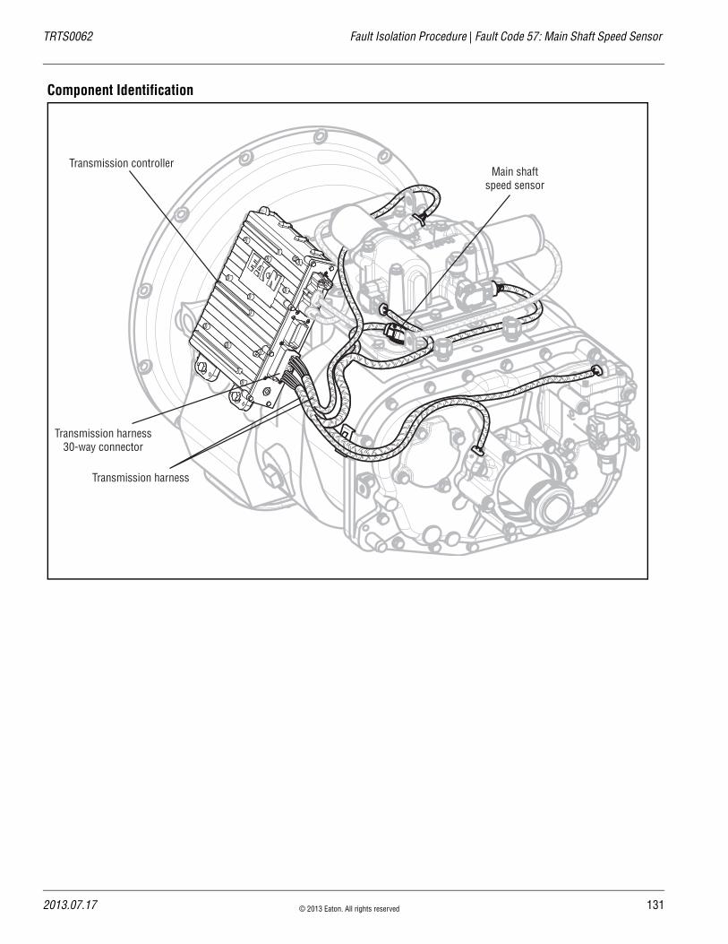
TRTS0062 Fault Isolation Procedure | Fault Code 57: Main Shaft Speed Sensor
Component Identification
Transmission controllerMain shaft
speed sensor
Transmission harness
Transmission harness30-way connector
2013.07.17 © 2013 Eaton. All rights reserved 131
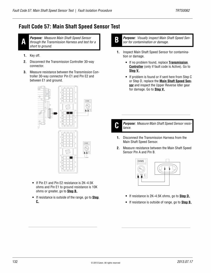
13
Fault Code 57: Main Shaft Speed Sensor Test | Fault Isolation Procedure TRTS0062
Fault Code 57: Main Shaft Speed Sensor Test
1. Key off.
2. Disconnect the Transmission Controller 30-way connector.
3. Measure resistance between the Transmission Con-troller 30-way connector Pin E1 and Pin E2 and between E1 and ground.
• If Pin E1 and Pin E2 resistance is 2K–4.5K ohms and Pin E1 to ground resistance is 10K ohms or greater, go to Step B.
• If resistance is outside of the range, go to Step C.
1. Inspect Main Shaft Speed Sensor for contamina-tion or damage.
• If no problem found, replace Transmission Controller (only if fault code is Active). Go to Step V.
• If problem is found or if sent here from Step C or Step D, replace the Main Shaft Speed Sen-sor and inspect the Upper Reverse Idler gear for damage. Go to Step V.
1. Disconnect the Transmission Harness from the Main Shaft Speed Sensor.
2. Measure resistance between the Main Shaft Speed Sensor Pin A and Pin B.
• If resistance is 2K–4.5K ohms, go to Step D.
• If resistance is outside of range, go to Step B.
APurpose: Measure Main Shaft Speed Sensor through the Transmission Harness and test for a short to ground.
OHMS
V COM A
K
J
H
G
F
E
D
C
B
A
3 2 1
3 2 1
OHMS
V COM A
K
J
H
G
F
E
D
C
B
A
3 2 1
3 2 1
GROUND
B Purpose: Visually inspect Main Shaft Speed Sen-sor for contamination or damage.
C Purpose: Measure Main Shaft Speed Sensor resis-tance.
A B
OHMS
V COM A
2 © 2013 Eaton. All rights reserved 2013.07.17

TRTS0062 Fault Isolation Procedure | Fault Code 57: Main Shaft Speed Sensor Test
1. Measure resistance between Main Shaft Speed Sensor Pin A and ground.
• If resistance is more than 10K ohms or open circuit [OL], replace the Transmission Har-ness. Go to Step V.
• If resistance is less than 10K ohms, go to Step B.
1. Key off.
2. Reconnect all connectors.
3. Verify proper installation of Speed Sensor.
4. Key on.
5. Clear codes, see “Clearing Fault Codes” on page 6.
6. Use Driving Techniques to attempt to reset the code, see “Driving Techniques” on page 7.
7. Check for codes, see “Clearing Fault Codes” on page 6.
• If no codes, test complete.
• If Fault Code 57 appears, go to Step A. to find error in testing.
• If code other than 57 appears, see “Fault Code Isolation Procedure Index” on page 12.
D Purpose: Test for a short to ground at the Main Shaft Speed Sensor.
A B
OHMS
V COM A
GROUND
V Purpose: Verify repair.
2013.07.17 © 2013 Eaton. All rights reserved 133

13
Fault Code 58: Output Shaft Speed Sensor | Fault Isolation Procedure TRTS0062
Fault Code 58: Output Shaft Speed SensorJ1587:MID 130 PID 191 FMI 2
OverviewFault Code 58 indicates an electrical problem in the Output Shaft Speed Sensor circuit. The signal from the sensor did not match the current operating conditions
DetectionA Speed Sensor is determined faulty when all Speed Sensor readings are compared and one sensor is inconsistent.
Conditions to Set Fault Code Active
FallbackThis fault causes a 5-speed fallback and the transmission stays in either low range or high range. When the vehicle comes to a stop, an attempt to shift into low range is made. The fallback causes a 1-speed fallback on transmissions with no auxiliary section.
Possible Causes This fault code can be caused by any of the following:
• Transmission Harness
• Output Shaft Speed Sensor
• Various transmission components
• Transmission Controller
• Failed or loose Tone Wheel
Additional Tools • Basic hand tools
• Eaton Test Adapter kit
• Digital volt/ohm meter
4 © 2013 Eaton. All rights reserved 2013.07.17

TRTS0062 Fault Isolation Procedure | Fault Code 58: Output Shaft Speed Sensor
Component Identification
Transmissioncontroller
Transmission harness
Transmission harness30-way connector
Output shaftspeed sensor
2013.07.17 © 2013 Eaton. All rights reserved 135
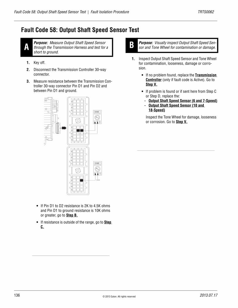
13
Fault Code 58: Output Shaft Speed Sensor Test | Fault Isolation Procedure TRTS0062
Fault Code 58: Output Shaft Speed Sensor Test
1. Key off.
2. Disconnect the Transmission Controller 30-way connector.
3. Measure resistance between the Transmission Con-troller 30-way connector Pin D1 and Pin D2 and between Pin D1 and ground.
• If Pin D1 to D2 resistance is 2K to 4.5K ohms and Pin D1 to ground resistance is 10K ohms or greater, go to Step B.
• If resistance is outside of the range, go to Step C.
1. Inspect Output Shaft Speed Sensor and Tone Wheel for contamination, looseness, damage or corro-sion.
• If no problem found, replace the Transmission Controller (only if fault code is Active). Go to Step V.
• If problem is found or if sent here from Step C or Step D, replace the:
- Output Shaft Speed Sensor (6 and 7-Speed)- Output Shaft Speed Sensor (10 and
18-Speed)
Inspect the Tone Wheel for damage, looseness or corrosion. Go to Step V.
APurpose: Measure Output Shaft Speed Sensor through the Transmission Harness and test for a short to ground.
GROUND
OHMS
V COM A
K
J
H
G
F
E
D
C
B
A
3 2 1
3 2 1
OHMS
V COM A
K
J
H
G
F
E
D
C
B
A
3 2 1
3 2 1
B Purpose: Visually inspect Output Shaft Speed Sen-sor and Tone Wheel for contamination or damage.
6 © 2013 Eaton. All rights reserved 2013.07.17
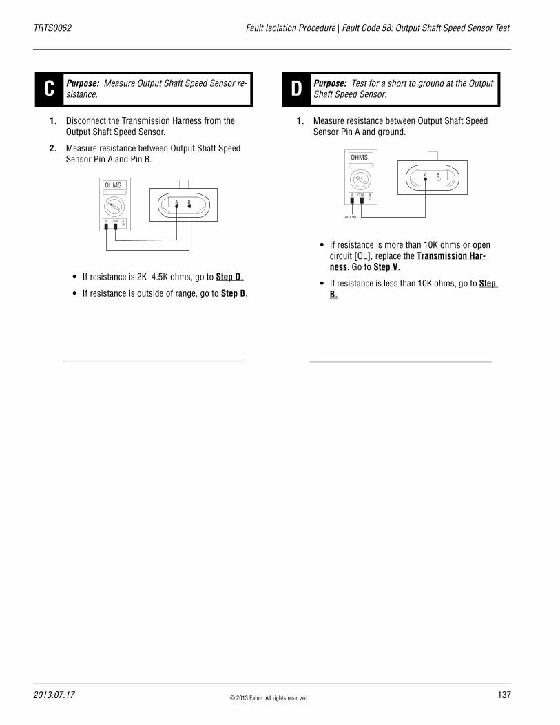
TRTS0062 Fault Isolation Procedure | Fault Code 58: Output Shaft Speed Sensor Test
1. Disconnect the Transmission Harness from the Output Shaft Speed Sensor.
2. Measure resistance between Output Shaft Speed Sensor Pin A and Pin B.
• If resistance is 2K–4.5K ohms, go to Step D.
• If resistance is outside of range, go to Step B.
1. Measure resistance between Output Shaft Speed Sensor Pin A and ground.
• If resistance is more than 10K ohms or open circuit [OL], replace the Transmission Har-ness. Go to Step V.
• If resistance is less than 10K ohms, go to Step B.
C Purpose: Measure Output Shaft Speed Sensor re-sistance.
A B
OHMS
V COM A
D Purpose: Test for a short to ground at the Output Shaft Speed Sensor.
A B
OHMS
V COM A
GROUND
2013.07.17 © 2013 Eaton. All rights reserved 137

13
Fault Code 58: Output Shaft Speed Sensor Test | Fault Isolation Procedure TRTS0062
1. Key off.
2. Reconnect all connectors.
3. Verify proper installation of Speed Sensor.
4. Key on.
5. Clear codes, see “Clearing Fault Codes” on page 6.
6. Use Driving Techniques to attempt to reset the code, see “Driving Techniques” on page 7.
7. Check for codes, see “Retrieving Fault Codes” on page 5.
• If no codes, test complete.
• If Fault Code 58 appears, go to Step A. to find error in testing.
• If code other than 58 appears, see “Fault Code Isolation Procedure Index” on page 12.
V Purpose: Verify repair.
8 © 2013 Eaton. All rights reserved 2013.07.17

TRTS0062 Fault Isolation Procedure | Fault Code 58: Output Shaft Speed Sensor Test
2013.07.17 © 2013 Eaton. All rights reserved 139
14
Fault Code 61: Rail Select Motor | Fault Isolation Procedure TRTS0062
Fault Code 61: Rail Select MotorJ1587:MID 130 SID 39 FMI 5, 6
OverviewFault Code indicates an electrical failure of the Rail Select Motor.
DetectionStarting at key on and throughout operation, the Transmis-sion Controller constantly measures the motor circuit. If a failure mode of short to battery, short to ground, or open circuit is detected, the fault code is set. The Transmission Controller also monitors the amount of current required to drive the motors. If the over current limit is exceeded, the fault code is also set.
Conditions to Set Fault Code Active
FallbackThis fault causes an in-place fallback.
Possible Causes This fault code can be caused by any of the following:
• Rail Select Motor
• Transmission Controller
Additional Tools • Basic hand tools
• Eaton Test Adapter kit
• Digital volt/ohm meter
0 © 2013 Eaton. All rights reserved 2013.07.17

TRTS0062 Fault Isolation Procedure | Fault Code 61: Rail Select Motor
Component Identification
Transmission controller
Rail select motor
Transmission harness30-way connector
Rail select motor 2-way connector
2013.07.17 © 2013 Eaton. All rights reserved 141

14
Fault Code 61: Rail Select Motor Test | Fault Isolation Procedure TRTS0062
Fault Code 61: Rail Select Motor Test
1. Key off.
2. Inspect main power 2-way connector terminals, in-line fuse holder, and power supply connections for integrity and corrosion.
• If no problem found, go to Step B.
• If problem is found, repair power/ground path for the main power supply. Go to Step V.
1. Key off.
2. Insert 20-amp fuse into main power 2-way connec-tor.
• If fuse blows immediately, go to Step C.
• If fuse does not blow immediately, repair wir-ing from the battery to the Transmission Con-troller. Go to Step V.
APurpose: Visually inspect the main power 2-way connector, in-line Fuse Holder and vehicle power supply connections.
A B
+–
+–
+–
+–
B Purpose: Check for proper power supply at Main Power Harness 2-way connector.
Main Power Supply 2-Way Connector20 Amp Fuse
30 Amp Fuse
2 © 2013 Eaton. All rights reserved 2013.07.17
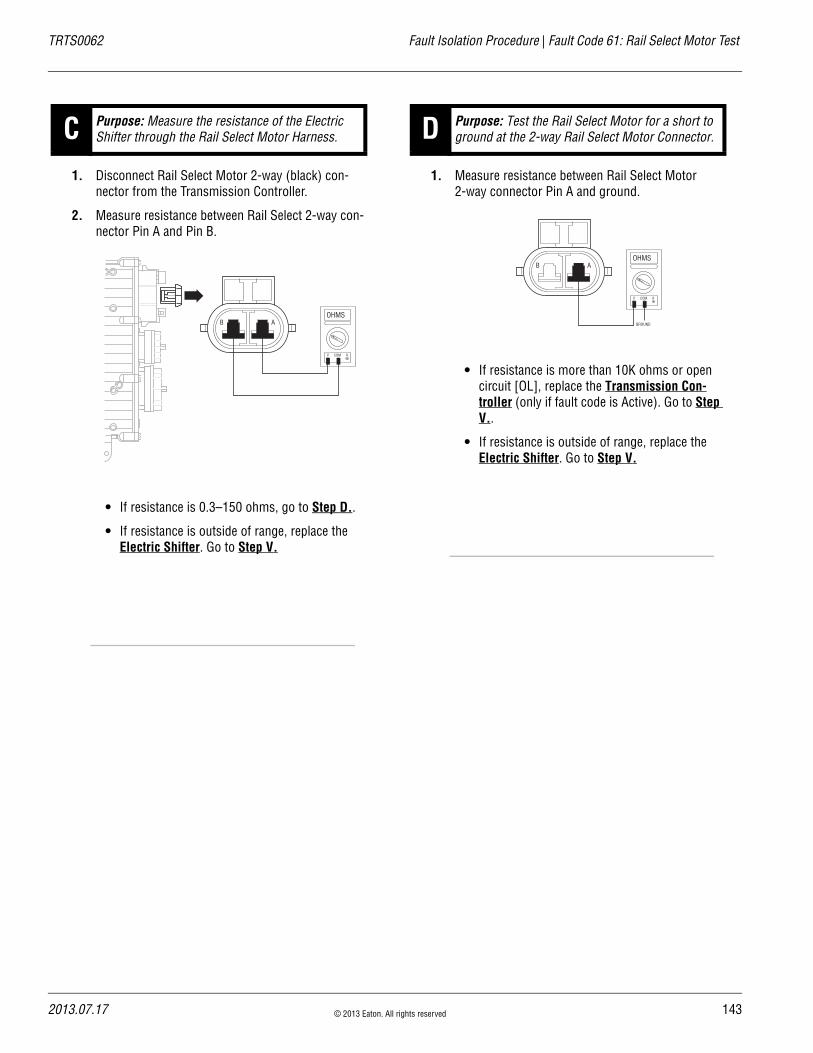
TRTS0062 Fault Isolation Procedure | Fault Code 61: Rail Select Motor Test
1. Disconnect Rail Select Motor 2-way (black) con-nector from the Transmission Controller.
2. Measure resistance between Rail Select 2-way con-nector Pin A and Pin B.
• If resistance is 0.3–150 ohms, go to Step D..
• If resistance is outside of range, replace the Electric Shifter. Go to Step V.
1. Measure resistance between Rail Select Motor 2-way connector Pin A and ground.
• If resistance is more than 10K ohms or open circuit [OL], replace the Transmission Con-troller (only if fault code is Active). Go to Step V..
• If resistance is outside of range, replace the Electric Shifter. Go to Step V.
C Purpose: Measure the resistance of the Electric Shifter through the Rail Select Motor Harness.
ABOHMS
V COM A
D Purpose: Test the Rail Select Motor for a short to ground at the 2-way Rail Select Motor Connector.
ABOHMS
V COM A
GROUND
2013.07.17 © 2013 Eaton. All rights reserved 143

14
Fault Code 61: Rail Select Motor Test | Fault Isolation Procedure TRTS0062
1. Key off.
2. Reconnect all connectors.
3. Key on.
4. Clear codes, see “Clearing Fault Codes” on page 6.
5. Use Driving Techniques to attempt to reset the code, see “Driving Techniques” on page 7.
6. Check for codes, see “Retrieving Fault Codes” on page 5.
• If no codes, Test complete.
• If Fault Code 61 appears, go to Step A. to find error in testing.
• If code other than 61 appears, see “Fault Code Isolation Procedure Index” on page 12.
V Purpose: Verify repair.
4 © 2013 Eaton. All rights reserved 2013.07.17

TRTS0062 Fault Isolation Procedure | Fault Code 61: Rail Select Motor Test
2013.07.17 © 2013 Eaton. All rights reserved 145
14
Fault Code 63: Gear Select Motor | Fault Isolation Procedure TRTS0062
Fault Code 63: Gear Select MotorJ1587:MID 130 SID 40 FMI 5, 6
OverviewFault Code 63 indicates an electrical failure of the Gear Select Motor.
DetectionStarting at key on and throughout operation, the Transmis-sion Controller constantly measures the motor circuit. If failure mode of short to battery, short to ground, or open circuit is detected, this fault code sets. The Transmission Controller also monitors the electrical current required to drive the motors. If the upper current limit is exceeded, the fault code is also set.
Conditions to Set Fault Code Active
FallbackThis fault causes an in-place fallback.
Possible Causes This fault code can be caused by any of the following:
• Gear Select Motor
• Transmission Controller
Additional Tools • Basic hand tools
• Eaton Test Adapter kit
• Digital volt/ohm meter
6 © 2013 Eaton. All rights reserved 2013.07.17
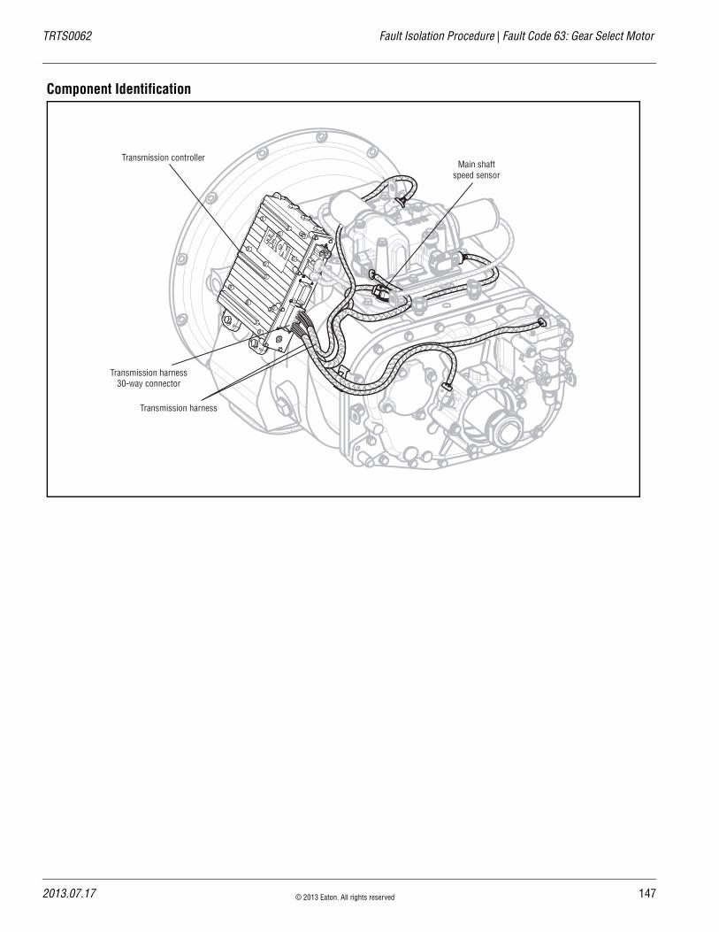
TRTS0062 Fault Isolation Procedure | Fault Code 63: Gear Select Motor
Component Identification
Transmission controllerMain shaft
speed sensor
Transmission harness
Transmission harness30-way connector
2013.07.17 © 2013 Eaton. All rights reserved 147

14
Fault Code 63: Gear Select Motor Test | Fault Isolation Procedure TRTS0062
Fault Code 63: Gear Select Motor Test
1. Key off.
2. Inspect main power 2-way connector terminals, in-line fuse holder, and power supply connections for integrity and corrosion.
• If no problem found, go to Step B.
• If problem is found, repair power/ground path for the main power supply. go to Step V.
1. Key off.
2. Insert 20-amp fuse into main power 2-way connec-tor.
• If fuse blows immediately, go to Step C.
• If fuse does not blow immediately, repair wir-ing from the battery to the Transmission Con-troller. go to Step V.
APurpose: Visually inspect the main power 2-way connector, in-line fuse holder and vehicle power supply connections for signs of damage.
A B
+–
+–
+–
+–
B Purpose: Check for proper power supply at Main Power Harness 2-way connector.
Main Power Supply 2-Way Connector20 Amp Fuse
30 Amp Fuse
8 © 2013 Eaton. All rights reserved 2013.07.17

TRTS0062 Fault Isolation Procedure | Fault Code 63: Gear Select Motor Test
1. Disconnect Gear Select Motor 2-way (blue) con-nector from the Transmission Controller.
2. Measure resistance between Gear Select 2-way connector Pin A and Pin B.
• If resistance is 0.3–150 ohms, go to Step D.
• If resistance is outside of range, replace the Electric Shifter. Go to Step V.
1. Measure resistance between Gear Select Motor 2-way connector Pin A and ground.
• If resistance is more than 10K ohms or open circuit [OL], replace the Transmission Con-troller (only if fault code is Active). Go to Step V.
• If resistance is outside of range, replace the Electric Shifter. Go to Step V.
C Purpose: Measure the resistance of the Electric Shifter through the Gear Select Motor Harness.
AB
OHMS
V COM A
D Purpose: Test the Gear Select Motor for a short to ground at the 2-way Gear Select Motor Connector.
AB
OHMS
V COM A
GROUND
2013.07.17 © 2013 Eaton. All rights reserved 149

15
Fault Code 63: Gear Select Motor Test | Fault Isolation Procedure TRTS0062
1. Key off.
2. Reconnect all connectors.
3. Key on.
4. Clear codes, see “Clearing Fault Codes” on page 6.
5. Use Driving Techniques to attempt to reset the code, see “Driving Techniques” on page 7.
6. Check for codes, see “Retrieving Fault Codes” on page 5.
• If no codes, Test complete.
• If Fault Code 63 appears, go to Step A. to find error in testing.
• If code other than 63 appears, see “Fault Code Isolation Procedure Index” on page 12.
V Purpose: Verify repair.
0 © 2013 Eaton. All rights reserved 2013.07.17

TRTS0062 Fault Isolation Procedure | Fault Code 63: Gear Select Motor Test
2013.07.17 © 2013 Eaton. All rights reserved 151

15
Fault Code 65: Logic Power | Fault Isolation Procedure TRTS0062
Fault Code 65: Logic PowerJ1587:MID 130 SID 251 FMI 4
OverviewFault Code 65 indicates the Transmission Controller has detected low transmission logic power to the Transmission Controller on vehicle interface 18-way connector Pin B1 and Pin E2.
DetectionStarting at key on and throughout operation, the Transmis-sion Controller constantly measures the motor voltage. If the reading is low, the fault code is set.
Conditions to Set Fault Code Active
FallbackThis fault causes an in-place fallback.
Possible Causes This fault code can be caused by any of the following:
• Battery Bus Fuse / Circuit Breaker is Open
• Low batteries
• Corroded or loose contacts
• Transmission Controller
• Shift Controller
Additional Tools • Basic hand tools
• Eaton Test Adapter Kit
• Digital volt/ohm meter
• Troubleshooting Guide
2 © 2013 Eaton. All rights reserved 2013.07.17

TRTS0062 Fault Isolation Procedure | Fault Code 65: Logic Power
Component Identification
30 AMP fuse
Battery power(non-switched power)
run to starter or batteries
All OEM responsible wiring shown is "typical". Consult specific application.(A1, E1) = +12 volt non-switched from battery (B1, E2) = +12 volt switched from shift control to transmission controller (A3, B3) = Signal returns, grounds, and general OEM wiring
VOLUMECONTROL
SERVICE
SHIFT
EATON FULLERTRANSMISSIONS
L
H
D
N
R
A1
A3
B1
E2
B3
E1
J1
J3
J2
K2
K3
K1
Vehicle bulkhead
connector
Shift control 30-way connector
Vehicle interface18-way connector
2013.07.17 © 2013 Eaton. All rights reserved 153
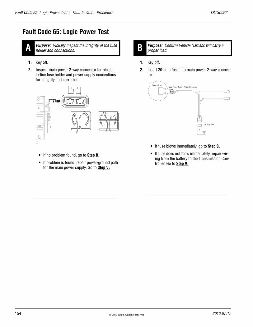
15
Fault Code 65: Logic Power Test | Fault Isolation Procedure TRTS0062
Fault Code 65: Logic Power Test
1. Key off.
2. Inspect main power 2-way connector terminals, in-line fuse holder and power supply connections for integrity and corrosion.
• If no problem found, go to Step B.
• If problem is found, repair power/ground path for the main power supply. Go to Step V.
1. Key off.
2. Insert 20-amp fuse into main power 2-way connec-tor.
• If fuse blows immediately, go to Step C.
• If fuse does not blow immediately, repair wir-ing from the battery to the Transmission Con-troller. Go to Step V.
A Purpose: Visually inspect the integrity of the fuse holder and connections.
A B
+–
+–
+–
+–
B Purpose: Confirm Vehicle Harness will carry a proper load.
Main Power Supply 2-Way Connector20 Amp Fuse
30 Amp Fuse
4 © 2013 Eaton. All rights reserved 2013.07.17

TRTS0062 Fault Isolation Procedure | Fault Code 65: Logic Power Test
1. Key off.
2. Disconnect negative (-) battery cable.
3. Disconnect the main power 2-way connector on the Transmission Controller.
4. Disconnect Shift Controller 30-way connector.
5. Measure resistance between Shift Controller 30-way Pin J2 and Pin K2.
• If Pin J2 and Pin K2 resistance is 0–0.3 ohms, go to Step F.
• If any of the above conditions are not met, go to Step D.
1. Key off.
2. Disconnect vehicle interface 18-way connector.
3. Measure resistance from:- Vehicle interface 18-way connector Pin B1 and
Shift Controller 30-way connector Pin J2- Shift Controller 30-way connector J2 and ground
• If resistance between Pin B1 and Pin J2 is 0–0.3 ohms and if Pin J2 and ground resis-tance is 10K ohms or open circuit [OL], go to Step E.
• If any of the above conditions are not met, replace OEM wiring from the Transmission Controller to the Shift Controller. Go to Step V.
C Purpose: Verify continuity of the Vehicle Harness.
OHMS
V COM A
K
J
H
G
F
E
D
C
B
A
3 2 1
3 2 1
D Purpose: Verify continuity of the Vehicle Harness and test for a short to ground
D
E
F
1 2 3
A
B
C
1 2 3
OHMS
V COM A
K
J
H
G
F
E
D
C
B
A
3 2 1
3 2 1
OHMS
V COM A
K
J
H
G
F
E
D
C
B
A
3 2 1
3 2 1
GROUND
2013.07.17 © 2013 Eaton. All rights reserved 155
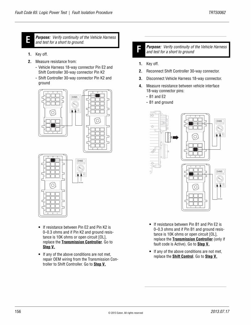
15
Fault Code 65: Logic Power Test | Fault Isolation Procedure TRTS0062
1. Key off.
2. Measure resistance from:- Vehicle Harness 18-way connector Pin E2 and
Shift Controller 30-way connector Pin K2- Shift Controller 30-way connector Pin K2 and
ground
• If resistance between Pin E2 and Pin K2 is 0–0.3 ohms and if Pin K2 and ground resis-tance is 10K ohms or open circuit [OL], replace the Transmission Controller. Go to Step V.
• If any of the above conditions are not met, repair OEM wiring from the Transmission Con-troller to Shift Controller. Go to Step V.
1. Key off.
2. Reconnect Shift Controller 30-way connector.
3. Disconnect Vehicle Harness 18-way connector.
4. Measure resistance between vehicle interface 18-way connector pins:- B1 and E2- B1 and ground
• If resistance between Pin B1 and Pin E2 is 0–0.3 ohms and if Pin B1 and ground resis-tance is 10K ohms or open circuit [OL], replace the Transmission Controller (only if fault code is Active). Go to Step V.
• If any of the above conditions are not met, replace the Shift Control. Go to Step V.
E Purpose: Verify continuity of the Vehicle Harness and test for a short to ground.
D
E
F
1 2 3
A
B
C
1 2 3
OHMS
V COM A
K
J
H
G
F
E
D
C
B
A
3 2 1
3 2 1
OHMS
V COM A
K
J
H
G
F
E
D
C
B
A
3 2 1
3 2 1
GROUND
F Purpose: Verify continuity of the Vehicle Harness and test for a short to ground
D
E
F
1 2 3
A
B
C
1 2 3
OHMS
V COM A
D
E
F
1 2 3
A
B
C
1 2 3
OHMS
V COM A
GROUND
6 © 2013 Eaton. All rights reserved 2013.07.17

TRTS0062 Fault Isolation Procedure | Fault Code 65: Logic Power Test
1. Key off.
2. Reconnect all connectors.
3. Key on.
4. Clear codes, see “Clearing Fault Codes” on page 6.
5. Use Driving Techniques to attempt to reset the code, see “Driving Techniques” on page 7.
6. Check for codes, see “Retrieving Fault Codes” on page 5.
• If no codes, test complete.
• If Fault Code 65 appears, go to Step A. to find error in testing.
• If code other than 65 appears, see “Fault Code Isolation Procedure Index” on page 12..
V Purpose: Verify repair.
2013.07.17 © 2013 Eaton. All rights reserved 157

15
Fault Code 71: Stuck Engaged | Fault Isolation Procedure TRTS0062
Fault Code 71: Stuck EngagedJ1587:MID 130 SID 60 FMI 7
OverviewFault Code 71 indicates the transmission was unable to move the front box to neutral during a shift request.
DetectionThe transmission detects this fault by attempting the same shifter actions 5 times and not sensing the desired position.
Conditions to Set Fault Code Active
FallbackThis fault causes an in-place fallback.
Possible Causes This fault code can be caused by any of the following:
• Low power to Gear Select Motor
• Gear Select Sensor
• Electric Shifter
• Yoke, Clutch, Main Shaft
• Shift Block
• Failed or misaligned Shift Block
• Dragging clutch
• Torque locked in gear
Additional Tools • Basic hand tools
• Eaton Test Adapter kit
• Digital volt/ohm meter
8 © 2013 Eaton. All rights reserved 2013.07.17

TRTS0062 Fault Isolation Procedure | Fault Code 71: Stuck Engaged
Component Identification
Shift bar housing
Main shaft
Gear select sensor
Electric shifter
2013.07.17 © 2013 Eaton. All rights reserved 159
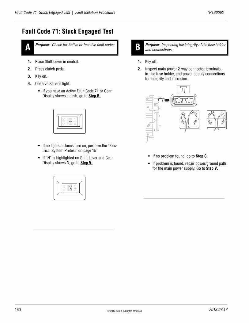
16
Fault Code 71: Stuck Engaged Test | Fault Isolation Procedure TRTS0062
Fault Code 71: Stuck Engaged Test
1. Place Shift Lever in neutral.
2. Press clutch pedal.
3. Key on.
4. Observe Service light.
• If you have an Active Fault Code 71 or Gear Display shows a dash, go to Step B.
• If no lights or tones turn on, perform the “Elec-trical System Pretest” on page 15
• If “N” is highlighted on Shift Lever and Gear Display shows N, go to Step V.
1. Key off.
2. Inspect main power 2-way connector terminals, in-line fuse holder, and power supply connections for integrity and corrosion.
• If no problem found, go to Step C.
• If problem is found, repair power/ground path for the main power supply. Go to Step V.
A Purpose: Check for Active or Inactive fault codes. B Purpose: Inspecting the integrity of the fuse holder and connections.
A B
+–
+–
+–
+–
0 © 2013 Eaton. All rights reserved 2013.07.17
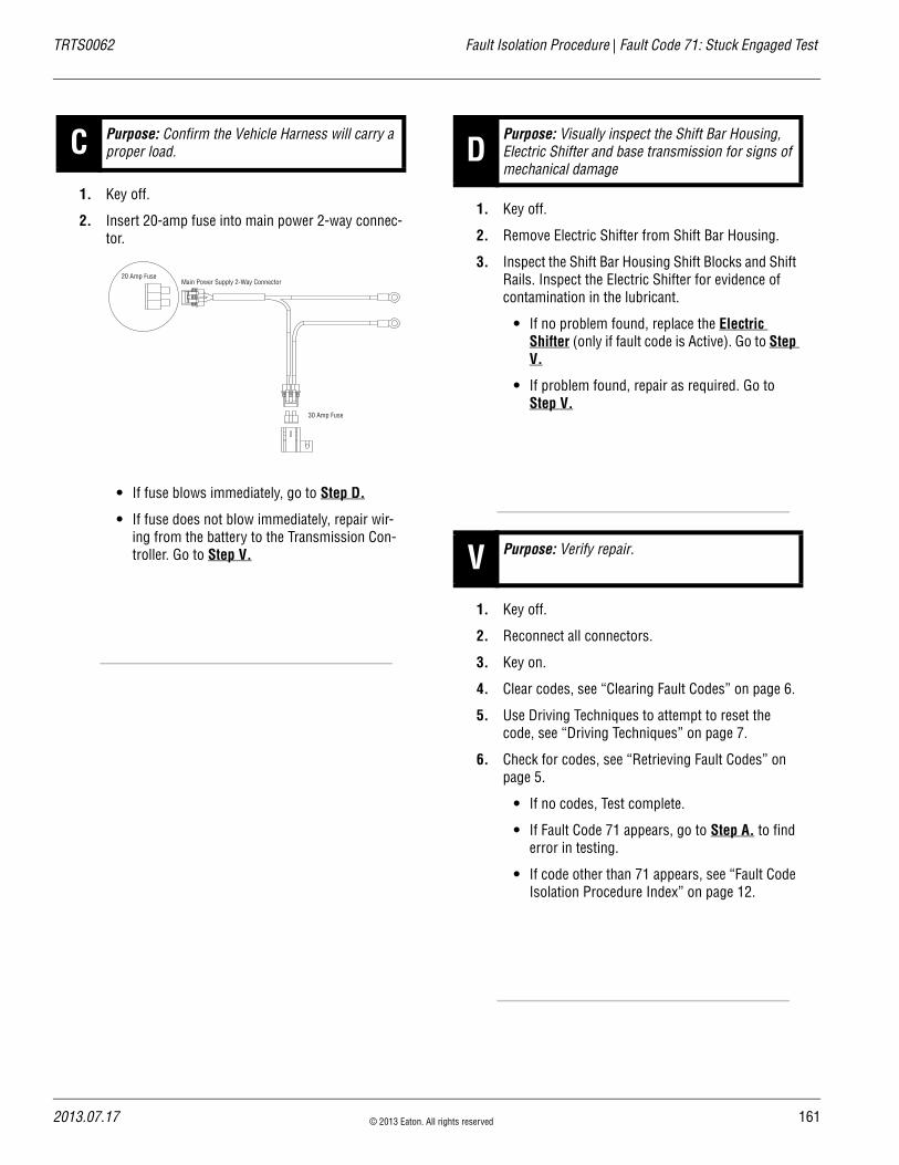
TRTS0062 Fault Isolation Procedure | Fault Code 71: Stuck Engaged Test
1. Key off.
2. Insert 20-amp fuse into main power 2-way connec-tor.
• If fuse blows immediately, go to Step D.
• If fuse does not blow immediately, repair wir-ing from the battery to the Transmission Con-troller. Go to Step V.
1. Key off.
2. Remove Electric Shifter from Shift Bar Housing.
3. Inspect the Shift Bar Housing Shift Blocks and Shift Rails. Inspect the Electric Shifter for evidence of contamination in the lubricant.
• If no problem found, replace the Electric Shifter (only if fault code is Active). Go to Step V.
• If problem found, repair as required. Go to Step V.
1. Key off.
2. Reconnect all connectors.
3. Key on.
4. Clear codes, see “Clearing Fault Codes” on page 6.
5. Use Driving Techniques to attempt to reset the code, see “Driving Techniques” on page 7.
6. Check for codes, see “Retrieving Fault Codes” on page 5.
• If no codes, Test complete.
• If Fault Code 71 appears, go to Step A. to find error in testing.
• If code other than 71 appears, see “Fault Code Isolation Procedure Index” on page 12.
C Purpose: Confirm the Vehicle Harness will carry a proper load.
Main Power Supply 2-Way Connector20 Amp Fuse
30 Amp Fuse
DPurpose: Visually inspect the Shift Bar Housing, Electric Shifter and base transmission for signs of mechanical damage
V Purpose: Verify repair.
2013.07.17 © 2013 Eaton. All rights reserved 161

16
Fault Code 72: Failed to Select Rail | Fault Isolation Procedure TRTS0062
Fault Code 72: Failed to Select RailJ1587:MID 130 SID 59 FMI 7
OverviewFault Code 72 indicates the transmission is unable to select the required rail during a shift.
DetectionThe transmission detects this by attempting the same shifter actions 5 times and not sensing the desired position.
Conditions to Set Fault Code Active
FallbackThis fault causes an in-place fallback.
Possible Causes This fault code can be caused by any of the following:
• Low power to Rail Motor
• Rail Select Motor
• Rail Select Sensor
• Shift Block
• Transmission Controller
• Rail slips into gear during vehicle transportation
Additional Tools • Basic hand tools
• Eaton Test Adapter kit
• Digital volt/ohm meter
2 © 2013 Eaton. All rights reserved 2013.07.17

TRTS0062 Fault Isolation Procedure | Fault Code 72: Failed to Select Rail
Component Identification
Rail select sensor
Electric shifter
Shift bar housing
2013.07.17 © 2013 Eaton. All rights reserved 163

16
Fault Code 72: Failed to Select Rail Test | Fault Isolation Procedure TRTS0062
Fault Code 72: Failed to Select Rail Test
1. Key off.
2. Inspect main power 2-way connector terminals, in-line fuse holder, and power supply connections for integrity and corrosion.
• If no problem found, go to Step B.
• If problem is found, repair power/ground path for the main power supply. Go to Step V.
1. Key off.
2. Insert 20-amp fuse into main power 2-way connec-tor.
• If fuse blows immediately, go to Step C.
• If fuse does not blow immediately, repair wir-ing from the battery to the Transmission Con-troller. Go to Step V.
A Purpose: Inspect the integrity of the Fuse Holder and connections.
A B
+–
+–
+–
+–
B Purpose: Confirm the Vehicle Harness will carry a proper load.
Main Power Supply 2-Way Connector20 Amp Fuse
30 Amp Fuse
4 © 2013 Eaton. All rights reserved 2013.07.17

TRTS0062 Fault Isolation Procedure | Fault Code 72: Failed to Select Rail Test
1. Key off.
2. Remove Electric Shifter from Shift Bar Housing.
3. Inspect the Shift Bar Housing Shift Blocks and Shift Rails. Inspect the Electric Shifter for evidence of lube contamination
• If no problem found, replace the Electric Shifter (only if fault code is Active). Go to Step V.
• If problem found, repair as required. Go to Step V.
1. Key off.
2. Reconnect all connectors.
3. Key on.
4. Clear codes, see “Clearing Fault Codes” on page 6.
5. Use Driving Techniques to attempt to reset the code, see “Driving Techniques” on page 7.
6. Check for codes, see “Retrieving Fault Codes” on page 5.
• If no codes, test complete.
• If Fault Code 72 appears, go to Step A. to find error in testing.
• If code other than 72 appears, see “Fault Code Isolation Procedure Index” on page 12.
CPurpose: Visually inspect the Shift Bar Housing Electric Shifter and base transmission for signs of mechanical damage.
V Purpose: Verify repair.
2013.07.17 © 2013 Eaton. All rights reserved 165

16
Fault Code 73: Failed to Engage Gear | Fault Isolation Procedure TRTS0062
Fault Code 73: Failed to Engage GearJ1587:MID 130 SID 58 FMI 7
OverviewFault Code 73 indicates the transmission is unable to engage the desired gear in the front box during a shift.
DetectionThe transmission detects this fault by attempting the same shifter action 5 times and not sensing the desired position.
Conditions to Set Fault Code Active
FallbackThis fault causes an in-place fallback.
Possible Causes This fault code can be caused by any of the following:
• Electric Shifter
• Yoke, Clutch, Main Shaft
• Gear Select Sensor
• Shift Block
Additional Tools • Basic hand tools
• Eaton Test Adapter kit
• Digital volt/ohm meter
6 © 2013 Eaton. All rights reserved 2013.07.17

TRTS0062 Fault Isolation Procedure | Fault Code 73: Failed to Engage Gear
Component Identification
Shift bar housing
Main shaft
Gear select sensor
Electric shifter
2013.07.17 © 2013 Eaton. All rights reserved 167
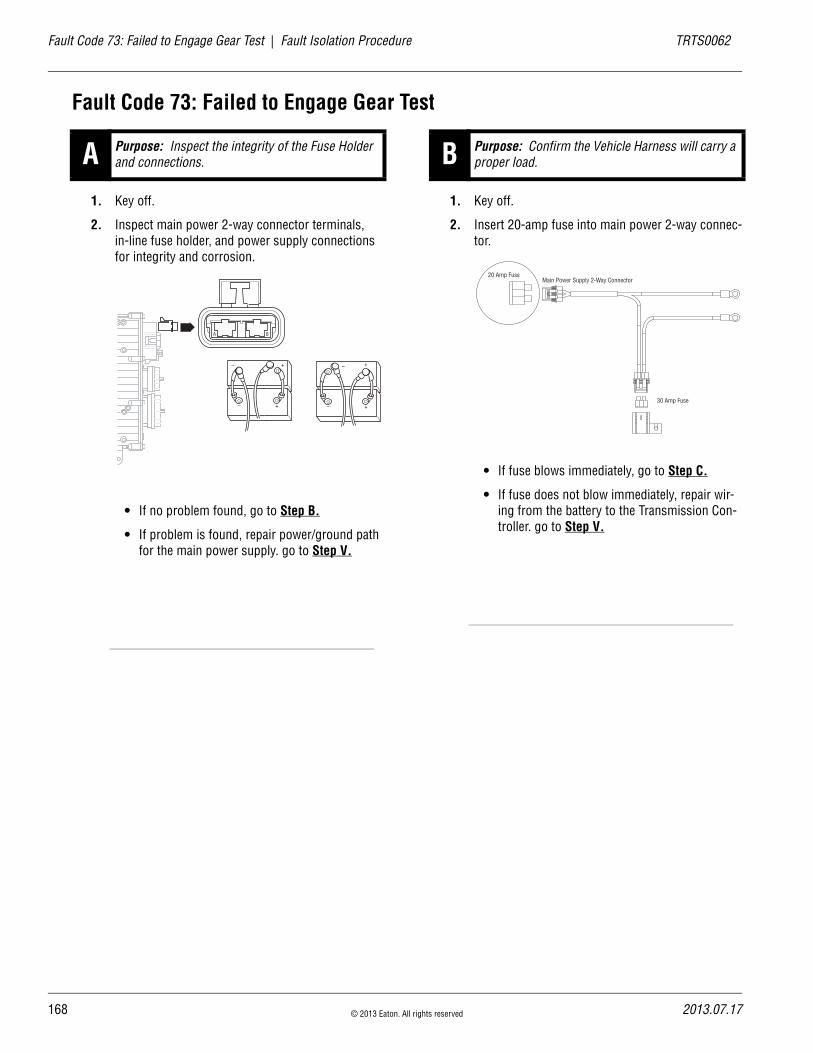
16
Fault Code 73: Failed to Engage Gear Test | Fault Isolation Procedure TRTS0062
Fault Code 73: Failed to Engage Gear Test
1. Key off.
2. Inspect main power 2-way connector terminals, in-line fuse holder, and power supply connections for integrity and corrosion.
• If no problem found, go to Step B.
• If problem is found, repair power/ground path for the main power supply. go to Step V.
1. Key off.
2. Insert 20-amp fuse into main power 2-way connec-tor.
• If fuse blows immediately, go to Step C.
• If fuse does not blow immediately, repair wir-ing from the battery to the Transmission Con-troller. go to Step V.
A Purpose: Inspect the integrity of the Fuse Holder and connections.
A B
+–
+–
+–
+–
B Purpose: Confirm the Vehicle Harness will carry a proper load.
Main Power Supply 2-Way Connector20 Amp Fuse
30 Amp Fuse
8 © 2013 Eaton. All rights reserved 2013.07.17

TRTS0062 Fault Isolation Procedure | Fault Code 73: Failed to Engage Gear Test
1. Key off.
2. Remove Electric Shifter from Shift Bar Housing.
3. Inspect the Shift Bar Housing Shift Blocks and Shift Rails. Inspect the Electric Shifter for evidence of contamination in the lubricant.
• If no problem found, replace the Electric Shifter (only if fault code is Active). Go to Step V.
• If problem found, repair as required. Go to Step V.
1. Key off.
2. Reconnect all connectors.
3. Key on.
4. Clear codes, see “Clearing Fault Codes” on page 6.
5. Use Driving Techniques to attempt to reset the code, see “Driving Techniques” on page 7.
6. Check for codes, see “Retrieving Fault Codes” on page 5.
• If no codes, Test complete.
• If Fault Code 73 appears, go to Step A. to find error in testing.
• If code other than 73 appears, see “Fault Code Isolation Procedure Index” on page 12.
CPurpose: Visually inspect the Shift Bar Housing Electric Shifter and base transmission for signs of mechanical damage.
V Purpose: Verify repair.
2013.07.17 © 2013 Eaton. All rights reserved 169

17
Fault Code 74: Failed to Synchronize | Fault Isolation Procedure TRTS0062
Fault Code 74: Failed to SynchronizeJ1587: MID 130 SID 54 FMI 7, 10, 12
OverviewFault Code 74 indicates the transmission is unable to use system controls to synchronize during a shift.
DetectionIf there is engine communication on the J1939 Link and the engine does not respond to transmission speed and torque commands, sets the code. Failure of the Inertia Brake sys-tem to slow the Input Shaft also sets the code.
Conditions to Set Fault Code Active
FallbackIf the failure occurs while moving, it could cause a 1-speed fallback. Once the vehicle is stopped, starting gear and reverse gear can be engaged. If the Inertia Brake system failed, it may be difficult to engage a gear from a stop if the Inertia Brake was providing assistance (due to a poorly adjusted clutch).
Possible Causes This fault code can be caused by any of the following:
• Clutch out of adjustment
• Damaged Input Shaft Brake
• Inertia Brake
• Engine Control System
Additional Tools • Basic hand tools
• Eaton Test Adapter kit
• PC-based Service Tool
0 © 2013 Eaton. All rights reserved 2013.07.17
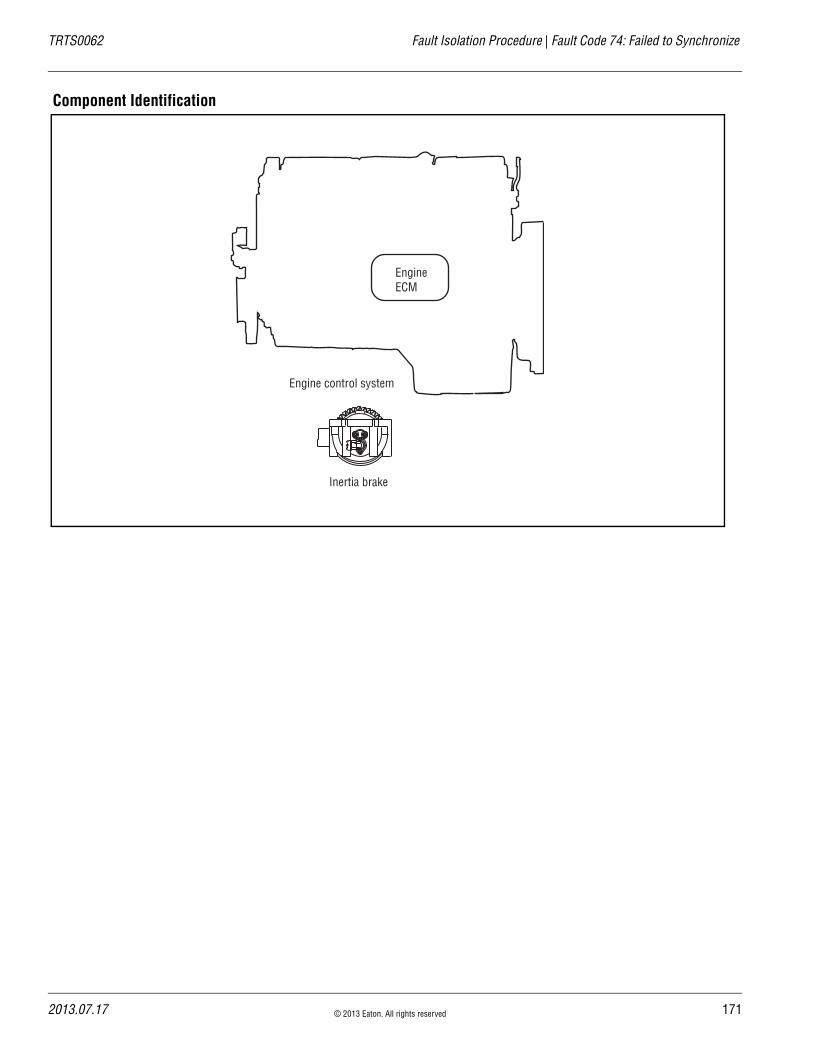
TRTS0062 Fault Isolation Procedure | Fault Code 74: Failed to Synchronize
Component Identification
Inertia brake
EngineECM
Engine control system
2013.07.17 © 2013 Eaton. All rights reserved 171
17
Fault Code 74: Failed to Synchronize Test | Fault Isolation Procedure TRTS0062
Fault Code 74: Failed to Synchronize Test
1. Is transmission equipped with an Inertia Brake?
• If the transmission is equipped with Inertia Brake, go to Step B.
• If the transmission is not equipped with Inertia Brake, go to Step C.
1. Key on.
2. Connect ServiceRanger, select “Advanced Product Functions”.
3. Start engine. PTO must be disengaged.
4. Select “Inertia Brake Test.”
5. Run test and follow instructions.
• Test passes, go to Step V..
• Test fails, replace the: - Inertia Brake (6-Speed)- Inertia Brake (7, 10 and 18-Speed)
Go to Step V.
• Test aborts, correct displayed test failure con-dition and retest.
1. Key on.
2. Retrieve codes, see “Retrieving Fault Codes” on page 5.
• If Fault Code 74 is Active, contact the OEM. Engine is failing to respond to the transmis-sions command during a shift.
• If Fault Code 74 is not Active, test complete.
1. Key on.
2. Clear codes, see “Clearing Fault Codes” on page 6.
3. Drive the vehicle and attempt to reset the code.
4. Check for codes, see “Retrieving Fault Codes” on page 5.
• If no codes, test complete.
• If Fault Code 74 appears, go to Step A. to find error in testing.
• If code other than 74 appears, see “Fault Code Isolation Procedure Index” on page 12.
A Purpose: Determine if truck has Inertia Brake in-stalled.
B Purpose: Verify proper operation of the Inertia Brake.
C Purpose: Check for Active or Inactive fault codes.
V Purpose: Verify repair.
2 © 2013 Eaton. All rights reserved 2013.07.17

TRTS0062 Fault Isolation Procedure | Fault Code 74: Failed to Synchronize Test
2013.07.17 © 2013 Eaton. All rights reserved 173

17
Fault Code 81: Gear Engagement Detected | Fault Isolation Procedure TRTS0062
Fault Code 81: Gear Engagement DetectedJ1587:MID 130 SID 47 FMI 7
OverviewThe Transmission Controller detected that the Shift Finger position indicates neutral and a comparison of Input and Main Shaft speeds indicate the transmission is in gear. The comparison of shaft speeds is only performed when the vehicle is moving and a shift is in process. This fault can only be set during a shift, and becomes inactive after power down.
DetectionThe fault is detected after the Transmission Controller pow-ers up and a non-neutral condition is detected during a shift.
FMI 7 - The Transmission Controller detected an inaccurate finger position.
Conditions to Set Fault Code Active
FallbackThis fault causes an in-place fallback. The transmission will remain in current gear.
Possible Causes This fault code can be caused by any of the following:
• Worn internal transmission components
Additional Tools • Basic hand tools
• Eaton Test Adapter kit
• PC-based Service Tool
4 © 2013 Eaton. All rights reserved 2013.07.17

TRTS0062 Fault Isolation Procedure | Fault Code 81: Gear Engagement Detected
Component Identification
Transmission
2013.07.17 © 2013 Eaton. All rights reserved 175

17
Fault Code 81: Gear Engagement Detected Test | Fault Isolation Procedure TRTS0062
Fault Code 81: Gear Engagement Detected Test
1. Key on.
2. Retrieve codes, see “Retrieving Fault Codes” on page 5.
• If Fault Code 81 is Active or Inactive: - Customer - Call Eaton at 1-800-826-HELP
(4357)- CSC - Call Technician Service.
A Purpose: Check for Active or Inactive fault codes.
6 © 2013 Eaton. All rights reserved 2013.07.17

TRTS0062 Fault Isolation Procedure | Fault Code 81: Gear Engagement Detected Test
2013.07.17 © 2013 Eaton. All rights reserved 177

17
Fault Code 83: Missing Lever | Fault Isolation Procedure TRTS0062
Fault Code 83: Missing LeverJ1587:MID 130 SID 18 FMI 14
OverviewFault Code 83 indicates the Shift Lever is not sensing any lever positions.
DetectionStarting at key on and throughout operation, the Shift Con-troller constantly measures the feedback from the Shift Lever circuit. If the Shift Lever reports no lever positions are sensed, the fault code is set.
Conditions to Set Fault Code Active
FallbackThis fault causes a down shift only fallback and shifts to neutral when the vehicle stops.
Possible Causes This fault code can be caused by any of the following:
• Shift Lever
Additional Tools • Basic hand tools
• Eaton Test Adapter kit
8 © 2013 Eaton. All rights reserved 2013.07.17

TRTS0062 Fault Isolation Procedure | Fault Code 83: Missing Lever
Component Identification
Shift Lever
2013.07.17 © 2013 Eaton. All rights reserved 179
18
Fault Code 83: Missing Lever Test | Fault Isolation Procedure TRTS0062
Fault Code 83: Missing Lever Test
1. Key on.
2. Retrieve Codes, see “Retrieving Fault Codes” on page 5.
• If Fault Code 83 is Active, replace the Shift Lever.
• If Fault Code 83 is Inactive, test complete.
A Purpose: Check for Active or Inactive fault codes.
0 © 2013 Eaton. All rights reserved 2013.07.17

TRTS0062 Fault Isolation Procedure | Fault Code 83: Missing Lever Test
2013.07.17 © 2013 Eaton. All rights reserved 181

18
Fault Code 91: Power Connection | Fault Isolation Procedure TRTS0062
Fault Code 91: Power ConnectionJ1587:MID 130 SID 236 FMI 5
OverviewFault Code 91 indicates an excessive resistance has been detected between the power supply source (battery or starter) and the Transmission Controller.
DetectionThe fault is detected during power down.
Conditions to Set Fault Code Active
FallbackNone
Possible Causes This fault code can be caused by any of the following:
• Vehicle Harness between battery or starter and Transmission Controller.
Additional Tools • Basic hand tools
• Eaton Test Adapter kit
2 © 2013 Eaton. All rights reserved 2013.07.17

TRTS0062 Fault Isolation Procedure | Fault Code 91: Power Connection
Component Identification
30 AMP fuse
Battery power(non-switched power)
run to starteror batteries
All OEM responsible wiring shown is "typical". Consult specific application.(B) = +12 volt non-switched from battery(A) = Signal returns, grounds, and general OEM wiring
Main power 2-way connector
B
A
2013.07.17 © 2013 Eaton. All rights reserved 183

18
Fault Code 91: Power Connection Test | Fault Isolation Procedure TRTS0062
Fault Code 91: Power Connection Test
1. Key off.
2. Inspect main power 2-way connector terminals, in-line Fuse Holder, and power supply connections for integrity and corrosion.
• If no problem found, go to Step B.
• If problem found, repair power/ground path for the main power supply. Go to Step V.
1. Key off.
2. Insert 20-amp fuse into main power 2-way connec-tor.
• If fuse blows immediately, go to Step V.
• If fuse does not blow immediately, repair wir-ing from the battery to the Transmission Con-troller. Go to Step V.
A Purpose: Inspect the integrity of the Fuse Holder and connections.
A B
+–
+–
+–
+–
B Purpose: Confirm the Vehicle Harness will carry a proper load.
Main Power Supply 2-Way Connector20 Amp Fuse
30 Amp Fuse
4 © 2013 Eaton. All rights reserved 2013.07.17

TRTS0062 Fault Isolation Procedure | Fault Code 91: Power Connection Test
1. Key off.
2. Clean and reconnect all connectors.
3. Key on.
4. Clear codes, see “Clearing Fault Codes” on page 6.
5. Use Driving Techniques to attempt to reset the code, see “Driving Techniques” on page 7.
6. Check for codes, see “Retrieving Fault Codes” on page 5.
• If no codes, test complete.
• If Fault Code 91 appears, go to Step A. to find error in testing.
• If code other than 91 appears, see “Fault Code Isolation Procedure Index” on page 12.
V Purpose: Verify repair.
2013.07.17 © 2013 Eaton. All rights reserved 185

18
Fault Code 92: Weak System Battery Voltage | Fault Isolation Procedure TRTS0062
Fault Code 92: Weak System Battery VoltageJ1587:MID 130 SID 168 FMI 14
OverviewFault Code 92 indicates the vehicle is supplying weak bat-tery voltage to the transmission.
DetectionThe fault is detected when vehicle battery voltage is below 9 volts for a period of at least 10 seconds.
Conditions to Set Fault Code Active
FallbackIf this fault occurs while moving, it causes an in-place fall-back. Once the vehicle is stopped, the starting gear and reverse can be engaged.
Possible Causes This fault code can be caused by the vehicle charging sys-tem or battery integrity.
Additional Tools • Basic hand tools
6 © 2013 Eaton. All rights reserved 2013.07.17

TRTS0062 Fault Isolation Procedure | Fault Code 92: Weak System Battery Voltage
Component Identification
VehicleChargingSystem
+–
+–
Batteries
2013.07.17 © 2013 Eaton. All rights reserved 187

18
Fault Code 92: Weak System Battery Voltage Test | Fault Isolation Procedure TRTS0062
Fault Code 92: Weak System Battery Voltage Test
1. Key off.
2. Determine if Fault Code 92 is present (Inactive or Active).
3. Inspect vehicle charging system and battery integ-rity to ensure battery voltage does not drop below 9 volts during normal operation.
• If no problem found, go to Step V.
• If problem is found, repair vehicle changing system and or battery integrity. go to Step V.
1. Key on.
2. Clear codes, see “Clearing Fault Codes” on page 6.
3. Use Driving Techniques to attempt to reset the code, see “Driving Techniques” on page 7.
4. Check for codes, see “Retrieving Fault Codes” on page 5.
• If no codes, Test complete.
• If Fault Code 92 appears, go to Step A. to find error in testing.
• If code other than 92 appears, see “Fault Code Isolation Procedure Index” on page 12.
A Purpose: Check for Active or Inactive fault codes. V Purpose: Verify repair.
8 © 2013 Eaton. All rights reserved 2013.07.17
TRTS0062 Fault Isolation Procedure | Fault Code 92: Weak System Battery Voltage Test
2013.07.17 © 2013 Eaton. All rights reserved 189

19
Fault Code 93: Loss of J1939 Communication from the Engine | Fault Isolation Procedure TRTS0062
Fault Code 93: Loss of J1939 Communication from the EngineJ1587:MID 130 SID 231 FMI 14
OverviewFault Code 93 indicates the Transmission Controller is not receiving J1939 messages from the engine.
DetectionThe fault is detected if J1939 communication from the engine is lost for 5 seconds.
Conditions to Set Fault Code Active
FallbackIf the fault occurs while moving, it causes a 1-speed fall-back. Once vehicle has stopped, the starting gear and reverse can be engaged. If the failure occurs at system ini-tialization, it causes an AutoSelect fallback mode.
Possible Causes This fault code can be caused by any of the following:
• OEM supplied J1939 harness
• Engine ECM
Additional Tools • Basic hand tools
0 © 2013 Eaton. All rights reserved 2013.07.17

TRTS0062 Fault Isolation Procedure | Fault Code 93: Loss of J1939 Communication from the Engine
Component Identification
TerminatingResistor
TerminatingResistor
EngineECM
Engine
J-1939 Data Link(OEM supplied)
2013.07.17 © 2013 Eaton. All rights reserved 191

19
Fault Code 93: Loss of J1939 Communication from the Engine Test | Fault Isolation Procedure TRTS0062
Fault Code 93: Loss of J1939 Communication from the Engine Test
1. Key on.
2. Determine if Fault Code 93 is present (either Inac-tive or Active).
3. Inspect OEM J1939 harness.
• If problem found with harness, repair OEM J1939 harness. go to Step V.
• If no problem is found with harness, problem exists with engine ECM. Repair according to vehicle manufacturer’s recommendations. Go to Step V.
1. Key off.
2. Reconnect all connectors.
3. Key on.
4. Clear codes, see “Clearing Fault Codes” on page 6.
5. Use Driving Techniques to attempt to reset the code, see “Driving Techniques” on page 7.
6. Check for codes, see “Retrieving Fault Codes” on page 5.
• If no codes, test complete.
• If Fault Code 93 appears, go to Step A. to find error in testing.
• If code other than 93 appears, see “Fault Code Isolation Procedure Index” on page 12.
A Purpose: Check for Active or Inactive fault codes. V Purpose: Verify repair.
2 © 2013 Eaton. All rights reserved 2013.07.17

TRTS0062 Fault Isolation Procedure | Fault Code 93: Loss of J1939 Communication from the Engine Test
2013.07.17 © 2013 Eaton. All rights reserved 193
19
Electrical System | Symptom Isolation Procedure TRTS0062
Electrical System
OverviewThe test does not relate to any specific fault code, but must be completed before performing “Fault Code Isolation Table” procedures. The test verifies the basic electrical inputs before testing individual circuits.
DetectionThere is no detection process specifically for the basic elec-trical supply; however, failures of this type are generally detected by the transmission or driver as some other type of fault code or symptom.
Conditions to Set Fault Code Active
FallbackThere is no fallback for the electrical pretest; however, it may effect other systems.
Possible Causes This pretest can be used for any of the following:
• Corroded power contacts
• Blown fuse
• Wiring Harness
• Low batteries
• Transmission Controller
Additional Tools • Basic hand tools
• Eaton Test Adapter Kit
• Digital volt/ohm meter
4 © 2013 Eaton. All rights reserved 2013.07.17

TRTS0062 Symptom Isolation Procedure | Electrical System
Component Identification
30 AMP fuse
Battery power(non-switched power)
run to starteror batteries
All OEM responsible wiring shown is "typical". Consult specific application.(B1, E2) = +12 volt non-switched from battery (A3, B3) = Signal returns, grounds, and general OEM wiring
VOLUMECONTROL
SERVICE
SHIFT
EATON FULLERTRANSMISSIONS
L
H
D
N
R
C1
Ignition power (switched power)run to main power lead that
feeds the ignition bus
10 AMP 12 volt onlyautomatic resetting
circuit breaker
10 AMP fuseOr
Vehicle bulkhead connector
J2
J3
K3
K2
B1
A3
B3
E2
Main power 2-way connector Shift control
30-way connector
Vehicle interface18-way connector
2013.07.17 © 2013 Eaton. All rights reserved 195
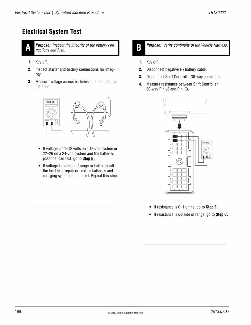
19
Electrical System Test | Symptom Isolation Procedure TRTS0062
Electrical System Test
1. Key off.
2. Inspect starter and battery connections for integ-rity.
3. Measure voltage across batteries and load test the batteries.
• If voltage is 11–13 volts on a 12-volt system or 22–26 on a 24-volt system and the batteries pass the load test, go to Step B.
• If voltage is outside of range or batteries fail the load test, repair or replace batteries and charging system as required. Repeat this step.
1. Key off.
2. Disconnect negative (-) battery cable.
3. Disconnect Shift Controller 30-way connector.
4. Measure resistance between Shift Controller 30-way Pin J3 and Pin K3.
• If resistance is 0–1 ohms, go to Step E.
• If resistance is outside of range, go to Step C.
A Purpose: Inspect the integrity of the battery con-nections and fuse.
VOLTS
VCOM A
+–
+–
B Purpose: Verify continuity of the Vehicle Harness.
OHMS
V COM A
K
J
H
G
F
E
D
C
B
A
3 2 1
3 2 1
6 © 2013 Eaton. All rights reserved 2013.07.17
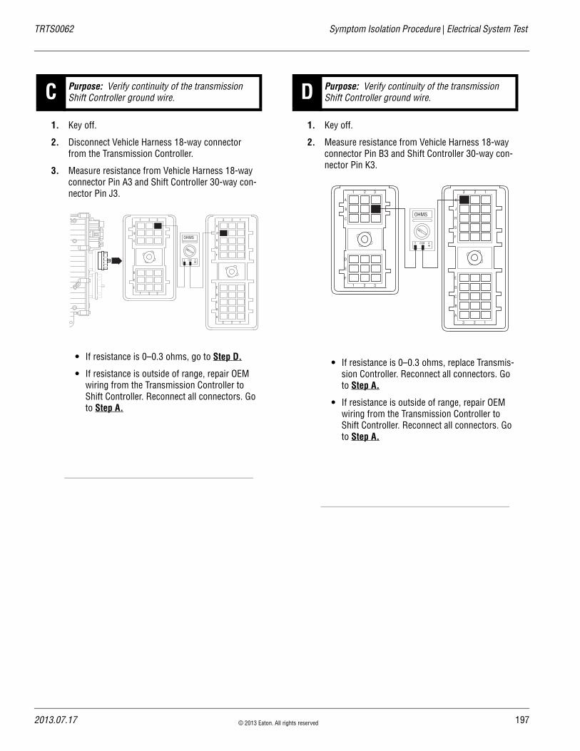
TRTS0062 Symptom Isolation Procedure | Electrical System Test
1. Key off.
2. Disconnect Vehicle Harness 18-way connector from the Transmission Controller.
3. Measure resistance from Vehicle Harness 18-way connector Pin A3 and Shift Controller 30-way con-nector Pin J3.
• If resistance is 0–0.3 ohms, go to Step D.
• If resistance is outside of range, repair OEM wiring from the Transmission Controller to Shift Controller. Reconnect all connectors. Go to Step A.
1. Key off.
2. Measure resistance from Vehicle Harness 18-way connector Pin B3 and Shift Controller 30-way con-nector Pin K3.
• If resistance is 0–0.3 ohms, replace Transmis-sion Controller. Reconnect all connectors. Go to Step A.
• If resistance is outside of range, repair OEM wiring from the Transmission Controller to Shift Controller. Reconnect all connectors. Go to Step A.
C Purpose: Verify continuity of the transmission Shift Controller ground wire.
OHMS
V COM A
K
J
H
G
F
E
D
C
B
A
3 2 1
3 2 1
D
E
F
1 2 3
A
B
C
1 2 3
D Purpose: Verify continuity of the transmission Shift Controller ground wire.
OHMS
V COM A
K
J
H
G
F
E
D
C
B
A
3 2 1
3 2 1
D
E
F
1 2 3
A
B
C
1 2 3
2013.07.17 © 2013 Eaton. All rights reserved 197

19
Electrical System Test | Symptom Isolation Procedure TRTS0062
1. Key off.
2. Measure resistance from Shift Control 30-way con-nector Pin J3 and negative (-) battery cable
• If resistance is 0–0.3 ohms, go to Step G.
• If resistance is outside of range, go to Step F.
1. Key off.
2. Disconnect the main power 2-way connector on the Transmission Controller.
3. Measure resistance between the main power 2-way connector Pin A and the negative (-) battery cable.
• If resistance is 0–0.3 ohms, replace the Trans-mission Controller. Reconnect all connectors. Go to Step A.
• If resistance is outside of range, repair ground path for the transmission. Reconnect all con-nectors. Go to Step A.
E Purpose: Measure resistance of the transmission Shift Controller ground.
OHMS
V COM A
K
J
H
G
F
E
D
C
B
A
3 2 1
3 2 1
+–
+–
F Purpose: Measure resistance of the Transmission Controller ground.
OHMS
V COM A
A B
+–
+–
8 © 2013 Eaton. All rights reserved 2013.07.17

TRTS0062 Symptom Isolation Procedure | Electrical System Test
1. Key off.
2. Measure resistance from Shift Controller 30-way connector Pin J1 and Pin K1
• If Pin J1 and Pin K1 resistance is 0–1 ohms, go to Step J.
• If the above conditions are not, go to Step H.
1. Key off.
2. Disconnect the Shift Controller 18-way connector.
3. Measure resistance from:- Vehicle Harness 18-way connector Pin A1 and
Shift Controller 30-way connector Pin J1.- Shift Controller 30-way connector J1 and ground.
• If Pin A1 and Pin J1 resistance is 0–0.3 ohms and if Pin J1 and ground resistance is more than 10K ohms or open circuit [OL], go to Step I.
• If any of the above conditions are not met, Repair OEM wiring from the Transmission Controller to Shift Controller. Reconnect all connectors. Go to Step A.
G Purpose: Verify continuity of the Vehicle Harness.
OHMS
V COM A
K
J
H
G
F
E
D
C
B
A
3 2 1
3 2 1
H Purpose: Verify continuity of the Shift Controller power wire and test for a short to ground.
K
J
H
G
F
E
D
C
B
A
3 2 1
3 2 1
D
E
F
1 2 3
A
B
C
1 2 3
OHMS
V COM A
K
J
H
G
F
E
D
C
B
A
3 2 1
3 2 1
OHMS
V COM A
GROUND
2013.07.17 © 2013 Eaton. All rights reserved 199
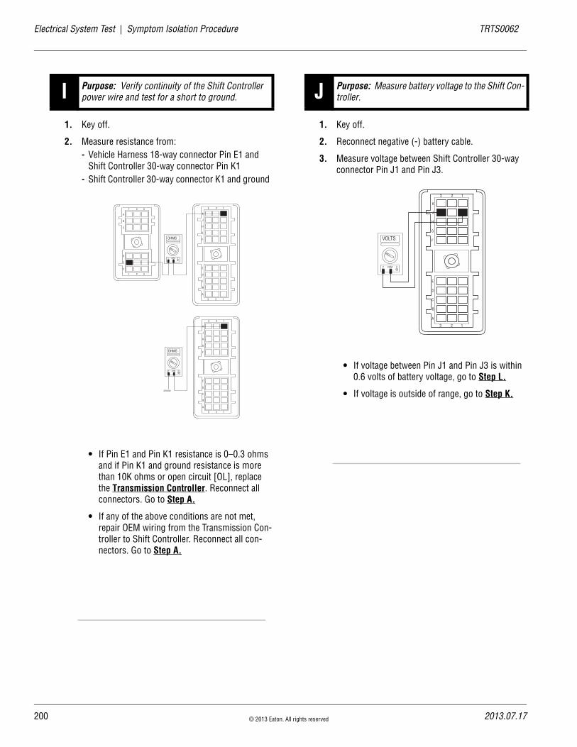
20
Electrical System Test | Symptom Isolation Procedure TRTS0062
1. Key off.
2. Measure resistance from:- Vehicle Harness 18-way connector Pin E1 and
Shift Controller 30-way connector Pin K1- Shift Controller 30-way connector K1 and ground
• If Pin E1 and Pin K1 resistance is 0–0.3 ohms and if Pin K1 and ground resistance is more than 10K ohms or open circuit [OL], replace the Transmission Controller. Reconnect all connectors. Go to Step A.
• If any of the above conditions are not met, repair OEM wiring from the Transmission Con-troller to Shift Controller. Reconnect all con-nectors. Go to Step A.
1. Key off.
2. Reconnect negative (-) battery cable.
3. Measure voltage between Shift Controller 30-way connector Pin J1 and Pin J3.
• If voltage between Pin J1 and Pin J3 is within 0.6 volts of battery voltage, go to Step L.
• If voltage is outside of range, go to Step K.
I Purpose: Verify continuity of the Shift Controller power wire and test for a short to ground.
K
J
H
G
F
E
D
C
B
A
3 2 1
3 2 1
D
E
F
1 2 3
A
B
C
1 2 3
OHMS
V COM A
K
J
H
G
F
E
D
C
B
A
3 2 1
3 2 1
OHMS
V COM A
GROUND
J Purpose: Measure battery voltage to the Shift Con-troller.
K
J
H
G
F
E
D
C
B
A
3 2 1
3 2 1
VOLTS
V COM A
0 © 2013 Eaton. All rights reserved 2013.07.17

TRTS0062 Symptom Isolation Procedure | Electrical System Test
1. Key off.
2. Disconnect the main power 2-way connector on the Transmission Controller.
3. Measure voltage between the main power 2-way connector Pin A and Pin B.
• If voltage is within 0.6 volts of battery voltage, replace the Transmission Controller. Recon-nect all connectors. Go to Step A.
• If voltage is outside of range, repair battery power supply to the transmission. Fuse may be blown. Reconnect all connectors. Go to Step A.
1. Key off.
2. Measure voltage between Shift Controller 30-way connector Pin C1 and Pin K3.
• If voltage is less than 0.6 volts, go to Step M.
• If voltage is outside of range and ignition has constant power, repair ignition supply to the transmission. Repeat this step.
K Purpose: Measure battery voltage to the Transmis-sion Controller.
VOLTS
V COM AA B
L Purpose: Measure battery voltage to the Shift Con-troller.
K
J
H
G
F
E
D
C
B
A
3 2 1
3 2 1
VOLTS
V COM A
2013.07.17 © 2013 Eaton. All rights reserved 201

20
Electrical System Test | Symptom Isolation Procedure TRTS0062
1. Key on.
2. Measure voltage between Shift Controller 30-way connector Pin C1 and Pin K3.
• If voltage is within 0.6 volts of battery voltage, test complete.
• If voltage is outside of range and the ignition has no power, repair ignition supply to the transmission. Repeat this step.
M Purpose: Measure battery voltage to the Shift Con-troller.
K
J
H
G
F
E
D
C
B
A
3 2 1
3 2 1
VOLTS
V COM A
2 © 2013 Eaton. All rights reserved 2013.07.17

TRTS0062 Symptom Isolation Procedure | Electrical System Test
2013.07.17 © 2013 Eaton. All rights reserved 203

20
Front Box Control | Symptom Isolation Procedure TRTS0062
Front Box Control
OverviewThis symptom-driven test is performed if the Service light is on constantly or a dash (-) is displayed on the Gear Dis-play, and there are no Active or Inactive codes
DetectionTurn the key on and watch the Gear Display. If the Gear Dis-play shows a dash (-) constantly, the Transmission Control-ler was not able to confirm front box control.
Any time the Service light is flashing, see the Diagnostic Procedure on page 4
Conditions to Set Fault Code Active
FallbackThis fault causes an in-place fallback while moving, and it causes a failure during system initialization. A dash (-) will appear on the Gear Display.
Possible Causes This symptom can be caused by any of the following:
• Electric Shifter
• Yoke, Clutch, Main Shift
• Shift Block
• Gear Select Sensor
Additional Tools • Basic hand tools
• Eaton Test Adapter Kit
• Digital volt/ohm meter
4 © 2013 Eaton. All rights reserved 2013.07.17
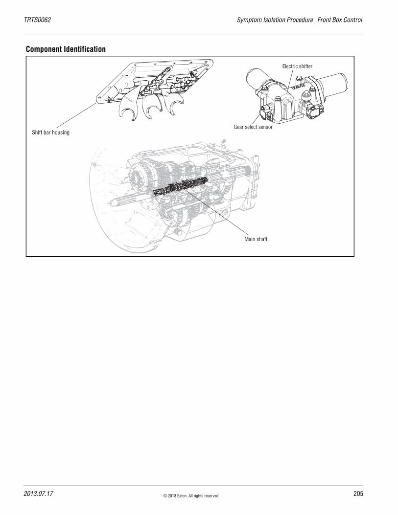
TRTS0062 Symptom Isolation Procedure | Front Box Control
Component Identification
Shift bar housing
Main shaft
Gear select sensor
Electric shifter
2013.07.17 © 2013 Eaton. All rights reserved 205
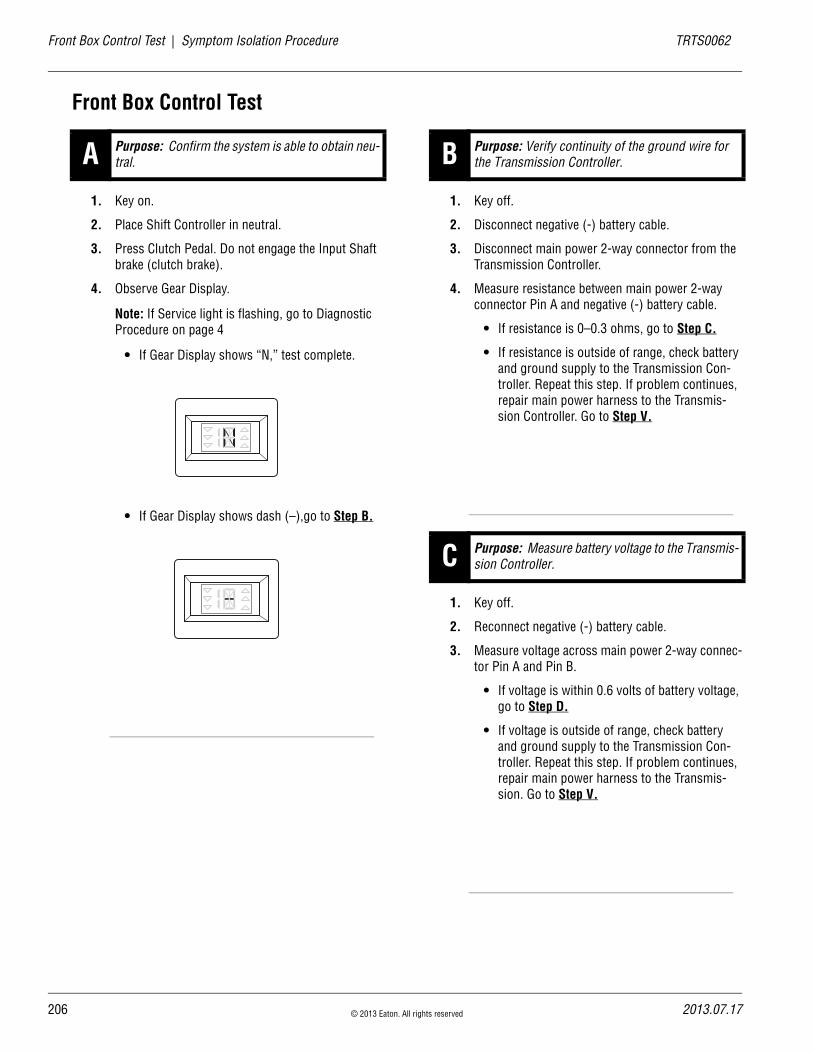
20
Front Box Control Test | Symptom Isolation Procedure TRTS0062
Front Box Control Test
1. Key on.
2. Place Shift Controller in neutral.
3. Press Clutch Pedal. Do not engage the Input Shaft brake (clutch brake).
4. Observe Gear Display.
Note: If Service light is flashing, go to Diagnostic Procedure on page 4
• If Gear Display shows “N,” test complete.
• If Gear Display shows dash (–),go to Step B.
1. Key off.
2. Disconnect negative (-) battery cable.
3. Disconnect main power 2-way connector from the Transmission Controller.
4. Measure resistance between main power 2-way connector Pin A and negative (-) battery cable.
• If resistance is 0–0.3 ohms, go to Step C.
• If resistance is outside of range, check battery and ground supply to the Transmission Con-troller. Repeat this step. If problem continues, repair main power harness to the Transmis-sion Controller. Go to Step V.
1. Key off.
2. Reconnect negative (-) battery cable.
3. Measure voltage across main power 2-way connec-tor Pin A and Pin B.
• If voltage is within 0.6 volts of battery voltage, go to Step D.
• If voltage is outside of range, check battery and ground supply to the Transmission Con-troller. Repeat this step. If problem continues, repair main power harness to the Transmis-sion. Go to Step V.
A Purpose: Confirm the system is able to obtain neu-tral. B Purpose: Verify continuity of the ground wire for
the Transmission Controller.
C Purpose: Measure battery voltage to the Transmis-sion Controller.
6 © 2013 Eaton. All rights reserved 2013.07.17
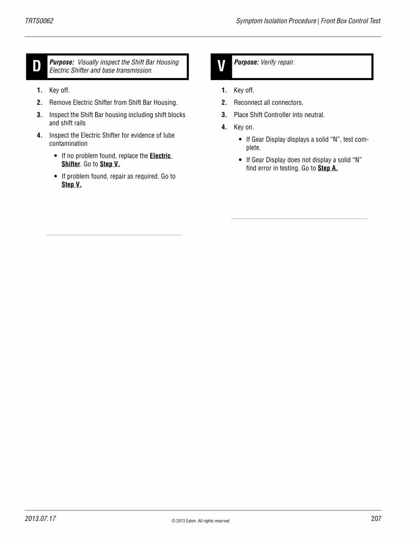
TRTS0062 Symptom Isolation Procedure | Front Box Control Test
1. Key off.
2. Remove Electric Shifter from Shift Bar Housing.
3. Inspect the Shift Bar housing including shift blocks and shift rails
4. Inspect the Electric Shifter for evidence of lube contamination
• If no problem found, replace the Electric Shifter. Go to Step V.
• If problem found, repair as required. Go to Step V.
1. Key off.
2. Reconnect all connectors.
3. Place Shift Controller into neutral.
4. Key on.
• If Gear Display displays a solid “N”, test com-plete.
• If Gear Display does not display a solid “N” find error in testing. Go to Step A.
D Purpose: Visually inspect the Shift Bar Housing Electric Shifter and base transmission. V Purpose: Verify repair.
2013.07.17 © 2013 Eaton. All rights reserved 207
20
Gear Display Power Supply | Symptom Isolation Procedure TRTS0062
Gear Display Power Supply
OverviewThis symptom-driven test is performed if Gear Display is not working, and there are no Active or Inactive codes.
DetectionThe Shift Controller has no fault detection capability for this failure. The failure is observed by the operator when operat-ing the vehicle. To observe this failure, operate the vehicle and monitor the Gear Display.
Conditions to Set Fault Code Active
FallbackThis symptom has no effect on vehicle operation; however, the Gear Display may not function.
Possible Causes This symptom can be caused by any of the following:
• Gear display
• Vehicle Harness
• Ignition power supply
• Shift Controller
Additional Tools • Basic hand tools
• Eaton Test Adapter kit
• Digital volt/ohm meter
8 © 2013 Eaton. All rights reserved 2013.07.17
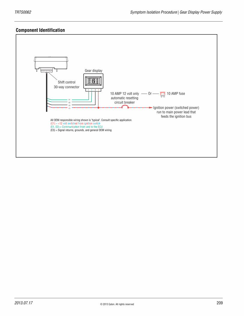
TRTS0062 Symptom Isolation Procedure | Gear Display Power Supply
Component Identification
Gear display
123 4
Ignition power (switched power)run to main power lead that
feeds the ignition bus
10 AMP 12 volt onlyautomatic resetting
circuit breaker
10 AMP fuseE1
E2
E3
C1
Or
Shift control30-way connector
All OEM responsible wiring shown is "typical". Consult specific application.(C1) = +12 volt switched from ignition switch(E1, E2) = Communication from and to the ECU(E3) = Signal returns, grounds, and general OEM wiring
2013.07.17 © 2013 Eaton. All rights reserved 209
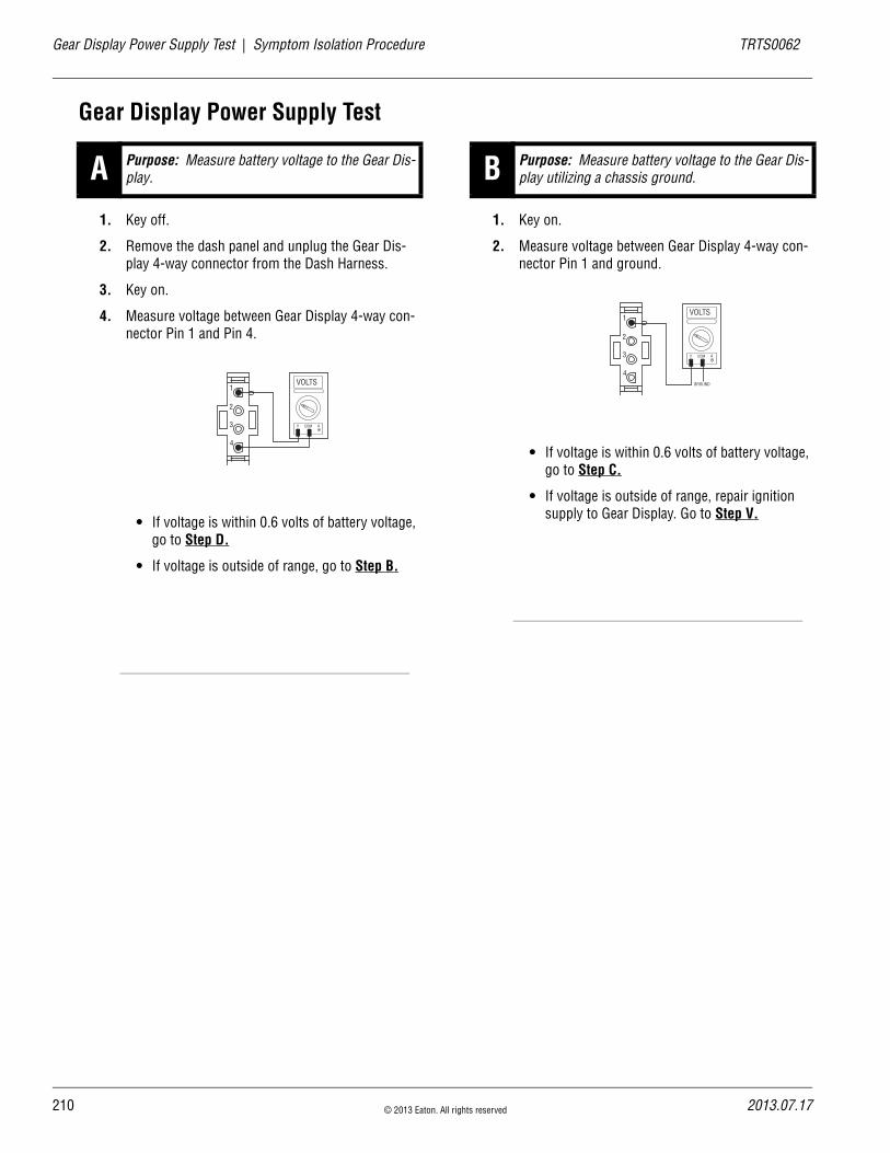
21
Gear Display Power Supply Test | Symptom Isolation Procedure TRTS0062
Gear Display Power Supply Test
1. Key off.
2. Remove the dash panel and unplug the Gear Dis-play 4-way connector from the Dash Harness.
3. Key on.
4. Measure voltage between Gear Display 4-way con-nector Pin 1 and Pin 4.
• If voltage is within 0.6 volts of battery voltage, go to Step D.
• If voltage is outside of range, go to Step B.
1. Key on.
2. Measure voltage between Gear Display 4-way con-nector Pin 1 and ground.
• If voltage is within 0.6 volts of battery voltage, go to Step C.
• If voltage is outside of range, repair ignition supply to Gear Display. Go to Step V.
A Purpose: Measure battery voltage to the Gear Dis-play.
2
1
3
4
VOLTS
V COM A
B Purpose: Measure battery voltage to the Gear Dis-play utilizing a chassis ground.
2
1
3
4
VOLTS
V COM A
GROUND
0 © 2013 Eaton. All rights reserved 2013.07.17

TRTS0062 Symptom Isolation Procedure | Gear Display Power Supply Test
1. Key off.
2. Disconnect Shift Controller 30-way connector.
3. Measure resistance between Shift Controller 30-way connector Pin E3 and Gear Display 4-way connector Pin 4.
• If resistance is within 0–0.3 ohms, go to Step D.
• If resistance is outside of range, repair Vehicle Harness between Gear Display and Shift Con-troller. Go to Step V.
1. Key on.
2. Disconnect Shift Controller 30-way connector.
3. Measure resistance between: - Shift Controller 30-way connector Pin E1 and
Gear Display 4-way connector Pin 3- Shift Controller 30-way connector Pin E1 and
ground
• If resistance between Pin E1 and Pin 3 is 0–0.3ohms and if resistance between Pin E1 and ground is 10K ohms or open circuit, go to Step E.
• If the above conditions are not met, repair Vehicle Harness between Gear Display and Shift Controller. Go to Step V.
C Purpose: Verify continuity of the Gear Display ground wire.
OHMS
V COM A
K
J
H
G
F
E
D
C
B
A
3 2 1
3 2 1
2
1
3
4
D Purpose: Verify continuity of the OEM data link to the OEM gear display and test for a short to ground.
OHMS
V COM A
2
1
3
4
K
J
H
G
F
E
D
C
B
A
3 2 1
3 2 1
GROUND
OHMS
V COM A
K
J
H
G
F
E
D
C
B
A
3 2 1
3 2 1
2013.07.17 © 2013 Eaton. All rights reserved 211
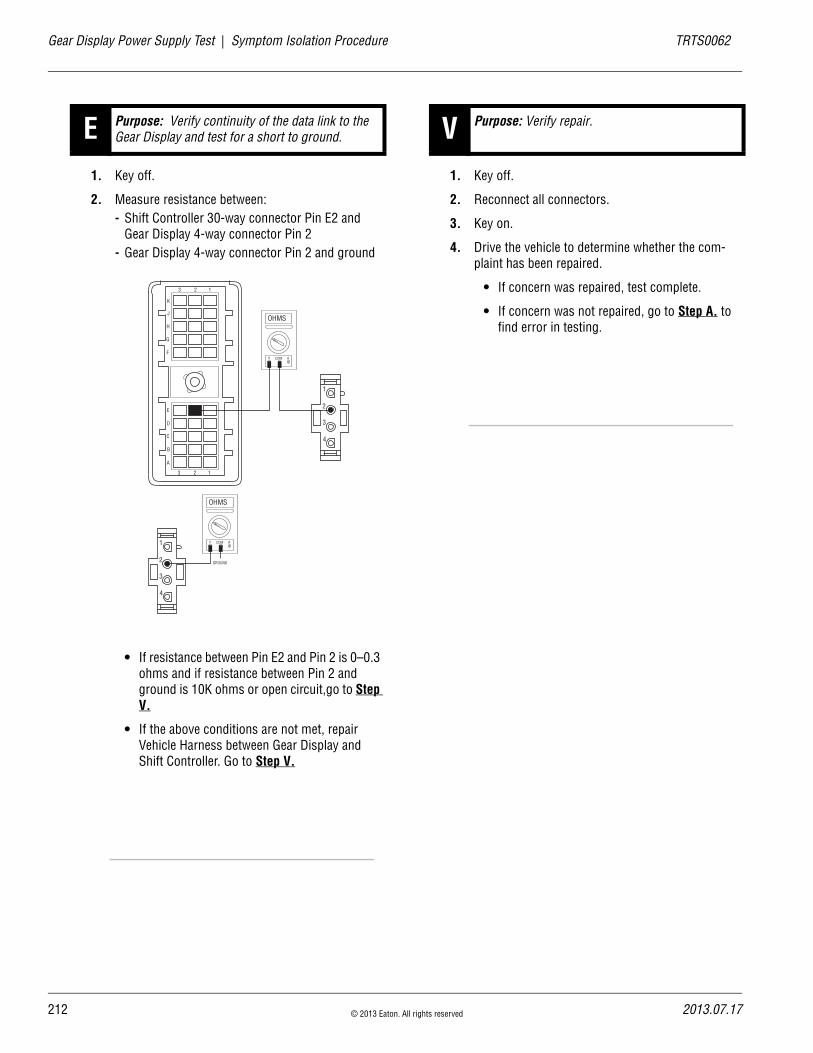
21
Gear Display Power Supply Test | Symptom Isolation Procedure TRTS0062
1. Key off.
2. Measure resistance between: - Shift Controller 30-way connector Pin E2 and
Gear Display 4-way connector Pin 2- Gear Display 4-way connector Pin 2 and ground
• If resistance between Pin E2 and Pin 2 is 0–0.3 ohms and if resistance between Pin 2 and ground is 10K ohms or open circuit,go to Step V.
• If the above conditions are not met, repair Vehicle Harness between Gear Display and Shift Controller. Go to Step V.
1. Key off.
2. Reconnect all connectors.
3. Key on.
4. Drive the vehicle to determine whether the com-plaint has been repaired.
• If concern was repaired, test complete.
• If concern was not repaired, go to Step A. to find error in testing.
E Purpose: Verify continuity of the data link to the Gear Display and test for a short to ground.
OHMS
V COM A
2
1
3
4
K
J
H
G
F
E
D
C
B
A
3 2 1
3 2 1
OHMS
V COM A
2
1
3
4
GROUND
V Purpose: Verify repair.
2 © 2013 Eaton. All rights reserved 2013.07.17

TRTS0062 Symptom Isolation Procedure | Gear Display Power Supply Test
2013.07.17 © 2013 Eaton. All rights reserved 213

21
Start Enable Relay Contact | Symptom Isolation Procedure TRTS0062
Start Enable Relay Contact
OverviewThis symptom-driven test is performed if the engine does not start with the Shift Lever in neutral, and there are no Active or Inactive codes.
DetectionThe Shift Controller has no fault detection capability for this failure. The failure is observed by the operator when driving the vehicle. To observe this failure, attempt to start the vehi-cle.
Conditions to Set Fault Code Active
FallbackThis symptom has no effect on vehicle operation; however, if the failure occurred before the engine was started, it is possible the engine will not start.
Possible Causes This symptom can be caused by any of the following:
• Start Enable Relay
• Starter Solenoid Wiring
Additional Tools • Basic hand tools
• Eaton Test Adapter Kit
• Digital volt/ohm meter
4 © 2013 Eaton. All rights reserved 2013.07.17
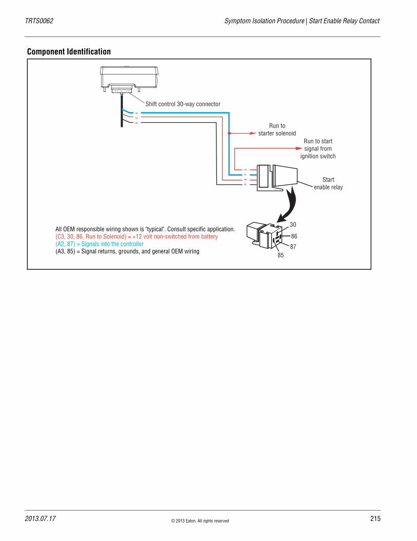
TRTS0062 Symptom Isolation Procedure | Start Enable Relay Contact
Component Identification
Startenable relay
Run to startsignal from
ignition switch
Run tostarter solenoid
A2
C3
A3
30
87
86
85
30
86
8785
All OEM responsible wiring shown is "typical". Consult specific application.(C3, 30, 86, Run to Solenoid) = +12 volt non-switched from battery (A2, 87) = Signals into the controller (A3, 85) = Signal returns, grounds, and general OEM wiring
Shift control 30-way connector
2013.07.17 © 2013 Eaton. All rights reserved 215

21
Start Enable Relay Contact Test | Symptom Isolation Procedure TRTS0062
Start Enable Relay Contact Test
1. Key off.
2. Disconnect Shift Controller 30-way connector.
3. Key on.
4. Engage Starter.
• If engine cranks, go to Step B.
• If engine does not crank, go to Step C.
1. Key off.
2. Remove positive (+) battery cable.
3. Measure resistance between Shift Controller 30-way connector Pin A2 and Pin K3.
• If resistance is more than 10K ohms or open circuit [OL], replace the Start Enable Relay. Go to Step V.
• If resistance is less than 10K ohms, starter solenoid circuit is short to ground. Repair as required. Go to Step V.
A Purpose: Verify start enable circuit operation. B Purpose: Verify Start Enable Latch wire is not shorted.
K
J
H
G
F
E
D
C
B
A
3 2 1
3 2 1
VOLTS
V COM A
6 © 2013 Eaton. All rights reserved 2013.07.17
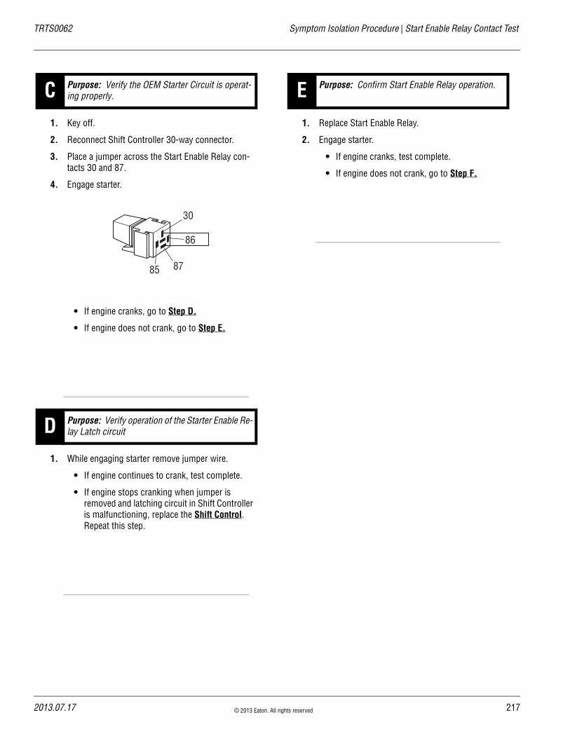
TRTS0062 Symptom Isolation Procedure | Start Enable Relay Contact Test
1. Key off.
2. Reconnect Shift Controller 30-way connector.
3. Place a jumper across the Start Enable Relay con-tacts 30 and 87.
4. Engage starter.
• If engine cranks, go to Step D.
• If engine does not crank, go to Step E.
1. While engaging starter remove jumper wire.
• If engine continues to crank, test complete.
• If engine stops cranking when jumper is removed and latching circuit in Shift Controller is malfunctioning, replace the Shift Control. Repeat this step.
1. Replace Start Enable Relay.
2. Engage starter.
• If engine cranks, test complete.
• If engine does not crank, go to Step F.
C Purpose: Verify the OEM Starter Circuit is operat-ing properly.
D Purpose: Verify operation of the Starter Enable Re-lay Latch circuit
30
86
8785
E Purpose: Confirm Start Enable Relay operation.
2013.07.17 © 2013 Eaton. All rights reserved 217
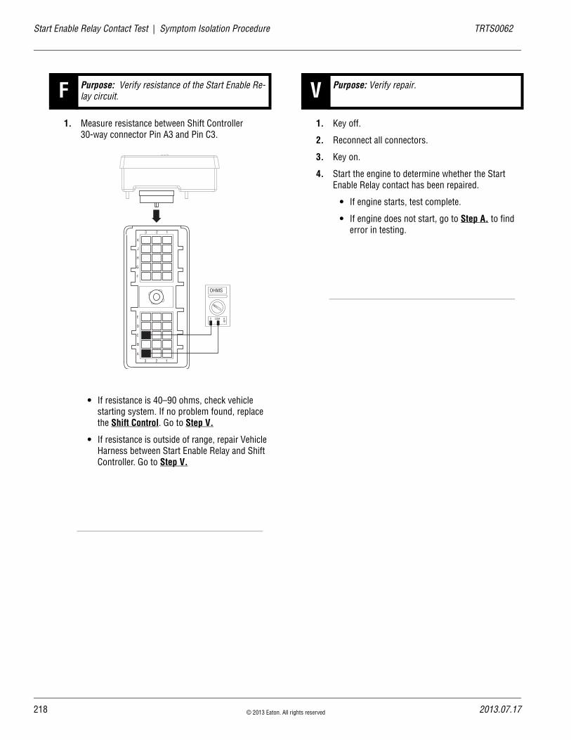
21
Start Enable Relay Contact Test | Symptom Isolation Procedure TRTS0062
1. Measure resistance between Shift Controller 30-way connector Pin A3 and Pin C3.
• If resistance is 40–90 ohms, check vehicle starting system. If no problem found, replace the Shift Control. Go to Step V.
• If resistance is outside of range, repair Vehicle Harness between Start Enable Relay and Shift Controller. Go to Step V.
1. Key off.
2. Reconnect all connectors.
3. Key on.
4. Start the engine to determine whether the Start Enable Relay contact has been repaired.
• If engine starts, test complete.
• If engine does not start, go to Step A. to find error in testing.
F Purpose: Verify resistance of the Start Enable Re-lay circuit.
K
J
H
G
F
E
D
C
B
A
3 2 1
3 2 1
OHMS
V COM A
V Purpose: Verify repair.
8 © 2013 Eaton. All rights reserved 2013.07.17
TRTS0062 Symptom Isolation Procedure | Start Enable Relay Contact Test
2013.07.17 © 2013 Eaton. All rights reserved 219

22
AutoShift Will Not Engage a Gear | Symptom Isolation Procedure TRTS0062
AutoShift Will Not Engage a Gear
OverviewThis symptom-driven test is performed if the transmission does not engage a gear, and there are no Active or Inactive codes.
DetectionIf the Shift Controller is unable to provide a fault code, the operator may observe this failure as the transmission not initiating or completing a shift. The operator may observe this failure as the transmission neutralizes.
Conditions to Set Fault Code Active
FallbackThere is no fallback mode for this symptom.
Possible Causes This symptom can be caused by any of the following:
• Input Shaft Speed Sensor
• Electric Shifter
• Transmission
• Gear Select Sensor
• Inertia Brake
• Clutch Brake
Additional Tools • Basic hand tools
• Eaton Test Adapter kit
• Digital volt/ohm meter
• PC-based Service Tool
0 © 2013 Eaton. All rights reserved 2013.07.17

TRTS0062 Symptom Isolation Procedure | AutoShift Will Not Engage a Gear
Component Identification
A
B
Input shaft speed sensor
Inertia brakeA
B
J1
J2
J3
D1D2
H1H2
All OEM responsible wiring shown is "typical". Consult specific application.(D1, D2) = Signals into the ECU(H1, H2) = Signal returns, grounds, and general OEM wiring
Transmission controller30-way connector
Main power2-way connector
Gear select sensor
Electric shifter
Shift Bar Housing
Main Shaft
2013.07.17 © 2013 Eaton. All rights reserved 221
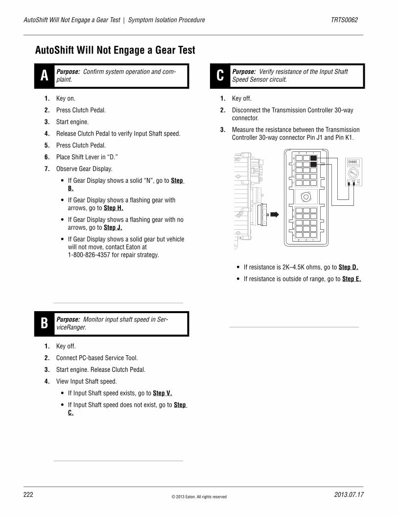
22
AutoShift Will Not Engage a Gear Test | Symptom Isolation Procedure TRTS0062
AutoShift Will Not Engage a Gear Test
1. Key on.
2. Press Clutch Pedal.
3. Start engine.
4. Release Clutch Pedal to verify Input Shaft speed.
5. Press Clutch Pedal.
6. Place Shift Lever in “D.”
7. Observe Gear Display.
• If Gear Display shows a solid “N”, go to Step B.
• If Gear Display shows a flashing gear with arrows, go to Step H.
• If Gear Display shows a flashing gear with no arrows, go to Step J.
• If Gear Display shows a solid gear but vehicle will not move, contact Eaton at 1-800-826-4357 for repair strategy.
1. Key off.
2. Connect PC-based Service Tool.
3. Start engine. Release Clutch Pedal.
4. View Input Shaft speed.
• If Input Shaft speed exists, go to Step V.
• If Input Shaft speed does not exist, go to Step C.
1. Key off.
2. Disconnect the Transmission Controller 30-way connector.
3. Measure the resistance between the Transmission Controller 30-way connector Pin J1 and Pin K1.
• If resistance is 2K–4.5K ohms, go to Step D.
• If resistance is outside of range, go to Step E.
A Purpose: Confirm system operation and com-plaint.
B Purpose: Monitor input shaft speed in Ser-viceRanger.
C Purpose: Verify resistance of the Input Shaft Speed Sensor circuit.
K
J
H
G
F
E
D
C
B
A
3 2 1
3 2 1
OHMS
V COM A
2 © 2013 Eaton. All rights reserved 2013.07.17

TRTS0062 Symptom Isolation Procedure | AutoShift Will Not Engage a Gear Test
1. Measure resistance between the Transmission Har-ness 30-way connector Pin J1 and ground.
• If resistance is more than 10K ohms or open circuit [OL], go to Step G.
• If resistance is less than 10K ohms, go to Step E.
1. Disconnect the Transmission Harness from the Input Shaft Speed Sensor.
2. Measure resistance between Input Shaft Speed Sensor Pin A and Pin B.
• If resistance is 2K–4.5K ohms, go to Step F.
• If resistance is outside of range, replace the:- Input Shaft Speed Sensor (6-Speed)- Input Shaft Speed Sensor (7, 10 and
18-Speed)
Go to Step V.
D Purpose: Test for a short to ground on the Input Shaft Speed Sensor circuit.
K
J
H
G
F
E
D
C
B
A
3 2 1
3 2 1
OHMS
V COM A
GROUND
E Purpose: Measure resistance of the Input Shaft Speed Sensor.
V COM A
A B
2013.07.17 © 2013 Eaton. All rights reserved 223

22
AutoShift Will Not Engage a Gear Test | Symptom Isolation Procedure TRTS0062
1. Measure resistance between Input Shaft Speed Sensor Pin A and ground.
• If resistance is 10K ohms or open circuit [OL], replace the Adapter Test Kit J43318. Go to Step V.
• If resistance is less than 10K ohms, replace the:
- Input Shaft Speed Sensor (6-Speed)- Input Shaft Speed Sensor (7, 10 and
18-Speed)
Go to Step V.
1. Key off.
2. Turn the Input Shaft and verify the Upper Counter-shaft is rotating.
• If Upper Countershaft is turning, replace the Transmission Controller. Go to Step V.
• If Upper Countershaft is not turning, contact Eaton at 1-800-826- 4357 for repair strategy.
1. Connect PC-based service tool.
2. Start engine.
3. View Input Shaft speed.
4. Press Clutch Pedal.
• If Input Shaft speed does not drop below 150 RPM, clutch is out of adjustment and/or Input Shaft Brake (Clutch Brake) is malfunctioning. Adjust clutch per manufacturer’s specifica-tions. Go to Step V.
If vehicle is equipped with an Inertia Brake, go to Step I.
• If Input Shaft speed drops below 150 RPM, test complete. Go to Step V.
F Purpose: Test for a short to ground on the Input Shaft Speed Sensor.
G Purpose: Verify the Countershaft is turning.
A B
H Purpose: Monitor Input Shaft speed in Ser-viceRanger.
4 © 2013 Eaton. All rights reserved 2013.07.17

TRTS0062 Symptom Isolation Procedure | AutoShift Will Not Engage a Gear Test
1. Key on.
2. Make sure the PTO is off.
3. Connect PC-based service tool and select “Advanced Product Function.”
4. Start engine.
5. Select “Inertia Brake Test.”
6. Run test and follow instructions.
• If test passes, test complete. Go to Step V.
• If test fails, replace the- Inertia Brake (6-Speed)- Inertia Brake (7, 10 and 18-Speed)
• After replacing the Inertia Brake, Go to Step V.
• If test aborts, correct displayed test failure condition and retest.
1. Key off.
2. Inspect main power 2-way connector terminals, in-line fuse holder and power supply connections for integrity and corrosion.
• If no problem found, go to Step K.
• If problem is found, repair power/ground path for the main power supply. Go to Step V.
I Purpose: Perform Inertia Brake Test using Ser-viceRanger. J Purpose: Inspect the integrity of the Fuse Holder
and connections.
A B
+–
+–
+–
+–
2013.07.17 © 2013 Eaton. All rights reserved 225

22
AutoShift Will Not Engage a Gear Test | Symptom Isolation Procedure TRTS0062
1. Key off.
2. Insert 20-amp fuse into Motor Supply 2-way con-nector.
• If fuse blows immediately, go to Step L.
• If fuse does not blow immediately, repair wir-ing from the battery to the Transmission Con-troller. Go to Step V.
1. Key off.
2. Remove Electric Shifter from Shift Bar Housing.
3. Inspect the Shift Bar Housing Shift Blocks, Shift Rails and Electric Shifter for evidence of lube con-tamination
• If problem is found, repair as required. Go to Step V.
• If no problem is found, replace the Electric Shifter. Go to Step V.
1. Key off.
2. Reconnect all connectors.
3. Key on.
4. Drive the vehicle to determine whether the com-plaint has been repaired.
• If the transmission engages a gear, test com-plete.
• If the transmission does not engage a gear, go to Step A. to find error in testing.
K Purpose: Verify the Vehicle Harness will carry a proper load.
Main Power Supply 2-Way Connector20 Amp Fuse
30 Amp Fuse
LPurpose: Visually inspect the Shift Bar Housing, Electric Shifter and base transmission for signs of mechanical damage.
V Purpose: Verify repair.
6 © 2013 Eaton. All rights reserved 2013.07.17

TRTS0062 Symptom Isolation Procedure | AutoShift Will Not Engage a Gear Test
2013.07.17 © 2013 Eaton. All rights reserved 227

22
UltraShift DM Will Not Engage a Gear | Symptom Isolation Procedure TRTS0062
UltraShift DM Will Not Engage a Gear
OverviewThis symptom-driven test is performed if the transmission does not engage a gear, and there are no Active or Inactive codes.
DetectionIf the Shift Controller is unable to provide a fault code, the operator may observe this failure as the transmission not initiating or completing a shift. The operator may observe this failure as the transmission neutralizes.
Conditions to Set Fault Code Active
FallbackThere is no fallback mode for this symptom.
Possible Causes This symptom can be caused by any of the following:
• Input Shaft Speed Sensor
• Electric Shifter
• Transmission
• Gear Select Sensor
• Inertia Brake
• Clutch
Additional Tools • Basic hand tools
• Eaton Test Adapter kit
• Digital volt/ohm meter
• PC-based Service Tool
8 © 2013 Eaton. All rights reserved 2013.07.17

TRTS0062 Symptom Isolation Procedure | UltraShift DM Will Not Engage a Gear
Component Identification
A
B
Input shaft speed sensor
Inertia brakeA
B
J1
J2
J3
D1D2
H1H2
All OEM responsible wiring shown is "typical". Consult specific application.(D1, D2) = Signals into the ECU(H1, H2) = Signal returns, grounds, and general OEM wiring
Transmission controller30-way connector
Main power2-way connector
Gear select sensor
Electric shifter
Shift Bar Housing
Main Shaft
2013.07.17 © 2013 Eaton. All rights reserved 229

23
UltraShift DM Will Not Engage a Gear Test | Symptom Isolation Procedure TRTS0062
UltraShift DM Will Not Engage a Gear Test
1. Key on.
2. Start engine.
3. Place Shift Lever in “D.”
4. Observe Gear Display.
• If Gear Display shows a solid “N”, go to Step B.
• If Gear Display shows a flashing gear with arrows, go to Step H.
• If Gear Display shows a flashing gear with no arrows, go to Step J.
• If Gear Display shows a solid gear but vehicle will not move, contact Eaton at 1-800-826-4357 for repair strategy.
1. Key off.
2. Connect PC-based Service Tool.
3. Start engine. Increase RPM and hold above 800 RPM.
4. View Input Shaft speed.
• If Input Shaft speed exists, contact Eaton at 1-800-826-4357 for repair strategy.
• If Input Shaft speed does not exist, go to Step C.
1. Key off.
2. Disconnect the Transmission Controller 30-way connector.
3. Measure the resistance between the Transmission Controller 30-way connector Pin J1 and Pin K1.
• If resistance is 2K–4.5K ohms, go to Step D.
• If resistance is outside of range, go to Step E.
A Purpose: Confirm system operation and com-plaint.
B Purpose: Monitor Input Shaft speed in Ser-viceRanger.
C Purpose: Verify resistance of the Input Shaft Speed Sensor circuit.
K
J
H
G
F
E
D
C
B
A
3 2 1
3 2 1
OHMS
V COM A
0 © 2013 Eaton. All rights reserved 2013.07.17

TRTS0062 Symptom Isolation Procedure | UltraShift DM Will Not Engage a Gear Test
1. Measure resistance between the Transmission Har-ness 30-way connector Pin J1 and ground.
• If resistance is more than 10K ohms or open circuit [OL], go to Step G.
• If resistance is less than 10K ohms, go to Step E.
1. Disconnect the Transmission Harness from the Input Shaft Speed Sensor.
2. Measure resistance between Input Shaft Speed Sensor Pin A and Pin B.
• If resistance is 2K–4.5K ohms, go to Step F.
• If resistance is outside of range, replace the:- Input Shaft Speed Sensor (6-Speed)- Input Shaft Speed Sensor (7, 10 and
18-Speed)
Go to Step V.
D Purpose: Test for a short to ground on the Input Shaft Speed Sensor circuit.
K
J
H
G
F
E
D
C
B
A
3 2 1
3 2 1
OHMS
V COM A
GROUND
E Purpose: Measure resistance of the Input Shaft Speed Sensor.
V COM A
A B
2013.07.17 © 2013 Eaton. All rights reserved 231

23
UltraShift DM Will Not Engage a Gear Test | Symptom Isolation Procedure TRTS0062
1. Measure resistance between Input Shaft Speed Sensor Pin A and ground.
• If resistance is 10K ohms or open circuit [OL], replace the Adapter Test Kit J43318. Go to Step V.
• If resistance is less than 10K ohms, replace the:
- Input Shaft Speed Sensor (6-Speed)- Input Shaft Speed Sensor (7, 10 and
18-Speed)
Go to Step V.
1. Key off.
2. Turn the Input Shaft and verify the Upper Counter-shaft is rotating.
• If Upper Countershaft is turning, replace Transmission Controller. Go to Step V.
• If Upper Countershaft is not turning, contact Eaton at 1-800-826- 4357 for repair strategy.
1. Connect PC-based service tool.
2. Start engine
3. View Input Shaft speed.
• If Input Shaft speed does not drop below 150 RPM, clutch is dragging. Go to Step I.
• If Input Shaft speed drops below 150 RPM, test complete. Go to Step V.
1. Key on.
2. Make sure the PTO is off.
3. Connect PC-based service tool and select “Advanced Product Function.”
4. Start engine.
5. Select “Inertia Brake Test.”
6. Run test and follow instructions.
• Test passes, replace Clutch. Go to Step V.
• Test fails, replace the: - Inertia Brake (6-Speed)- Inertia Brake (7, 10 and 18-Speed)
Go to Step V.
• Test aborts, correct displayed test failure con-dition and retest.
F Purpose: Test for a short to ground on the Input Shaft Speed Sensor.
G Purpose: Verify the Countershaft is turning.
OHMS
V COM A
A B
GROUND
H Purpose: Monitor Input Shaft speed in Ser-viceRanger.
I Purpose: Perform Inertia Brake Test using Ser-viceRanger.
2 © 2013 Eaton. All rights reserved 2013.07.17
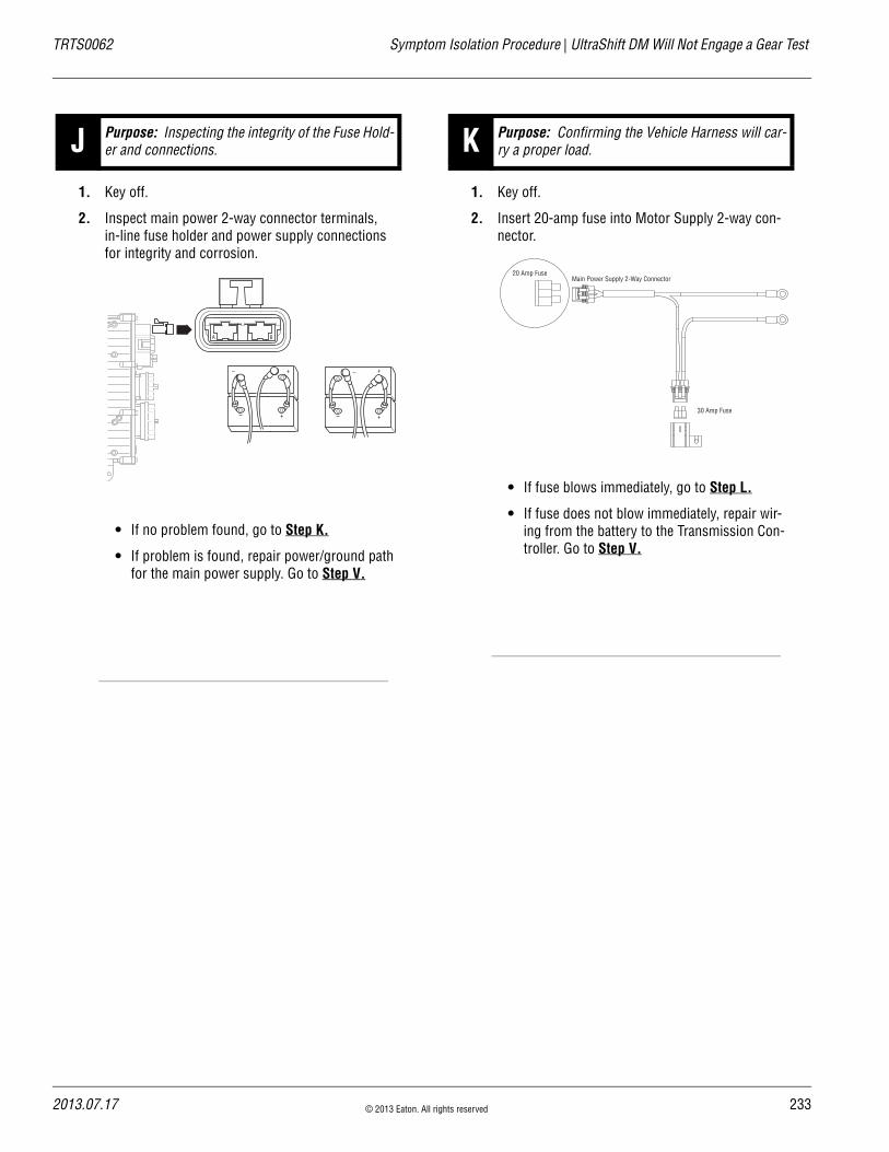
TRTS0062 Symptom Isolation Procedure | UltraShift DM Will Not Engage a Gear Test
1. Key off.
2. Inspect main power 2-way connector terminals, in-line fuse holder and power supply connections for integrity and corrosion.
• If no problem found, go to Step K.
• If problem is found, repair power/ground path for the main power supply. Go to Step V.
1. Key off.
2. Insert 20-amp fuse into Motor Supply 2-way con-nector.
• If fuse blows immediately, go to Step L.
• If fuse does not blow immediately, repair wir-ing from the battery to the Transmission Con-troller. Go to Step V.
J Purpose: Inspecting the integrity of the Fuse Hold-er and connections.
A B
+–
+–
+–
+–
K Purpose: Confirming the Vehicle Harness will car-ry a proper load.
Main Power Supply 2-Way Connector20 Amp Fuse
30 Amp Fuse
2013.07.17 © 2013 Eaton. All rights reserved 233

23
UltraShift DM Will Not Engage a Gear Test | Symptom Isolation Procedure TRTS0062
1. Key off.
2. Remove Electric Shifter from Shift Bar Housing.
3. Inspect the Shift Bar Housing Shift Blocks, Shift Rails and Electric Shifter for evidence of lube con-tamination
• If problem is found, repair as required. Go to Step V.
• If no problem is found, replace the Electric Shifter. Go to Step V.
1. Key off.
2. Reconnect all connectors.
3. Key on.
4. Drive the vehicle to determine whether the com-plaint has been repaired.
• If the transmission engages a gear, test com-plete.
• If the transmission does not engage a gear, go to Step A. to find error in testing.
L Purpose: Visually inspect the shift bar housing Electric Shifter and base transmission. V Purpose: Verify repair.
4 © 2013 Eaton. All rights reserved 2013.07.17

TRTS0062 Symptom Isolation Procedure | UltraShift DM Will Not Engage a Gear Test
2013.07.17 © 2013 Eaton. All rights reserved 235

23
UltraShift ASW Will Not Engage a Gear | Symptom Isolation Procedure TRTS0062
UltraShift ASW Will Not Engage a Gear
OverviewThis symptom-driven test is performed if the transmission does not engage a gear, and there are no Active or Inactive codes.
DetectionIf the Shift Controller is unable to provide a fault code, the operator may observe this failure as the transmission not initiating or completing a shift. The operator may observe this failure as the transmission neutralizes.
Conditions to Set Fault Code Active
FallbackThere is no fallback mode for this symptom.
Possible Causes This symptom can be caused by any of the following:
• Fluid level
• Inertia Brake
• Electric Shifter
• PTO circuit
• Transmission
Additional Tools • Basic hand tools
• Eaton Test Adapter kit
• Digital volt/ohm meter
• PC-based Service Tool
6 © 2013 Eaton. All rights reserved 2013.07.17

TRTS0062 Symptom Isolation Procedure | UltraShift ASW Will Not Engage a Gear
Component Identification
Inertia brakeA
B
J1
J2
J3
H1H2
All OEM responsible wiring shown is "typical". Consult specific application. (H1, H2) = Signal returns, grounds, and general OEM wiring
Transmission controller30-way connector
Main power2-way connector
Gear select sensor
Electric shifter
2013.07.17 © 2013 Eaton. All rights reserved 237

23
UltraShift ASW Will Not Engage a Gear Test | Symptom Isolation Procedure TRTS0062
UltraShift ASW Will Not Engage a Gear Test
1. Key on.
2. Start engine.
3. Place Shift Lever in “D.”
4. Observe Gear Display.
• If Gear Display shows a solid start gear, but vehicle will not move, go to Step B.
• If Gear Display shows a flashing gear with arrows, go to Step C.
• If Gear Display shows a flashing gear with no arrows, go to Step D.
• If Gear Display shows a Direct Drive Gear, go to Step G.
1. Place transmission in neutral.
2. Allow engine to idle at 600–700 RPM for a mini-mum of 2 minutes. Ensure transmission fluid tem-perature is 60–120° F (16–49° C).
3. Check wet clutch fluid level.
• If fluid level is at “Cold” or “Full” mark, remove flywheel inspection cover and inspect rubber coupler for damage or shear. If no damage observed, go to Step C.. If damaged observed, service Torsional Coupler.
• If fluid level is below the “Cold” or “Full” mark, correct fluid level, check for leaks. Go to Step V.
1. Key on.
2. Make sure PTO is off.
3. Connect PC-based service tool and select “Advanced Product Function.”
4. Start engine.
5. Select “Inertia Brake Test.”
6. Run test and follow instructions.
• Test passes, test complete. Go to Step C.
• Test fails, replace the:- Inertia Brake (6-Speed)- Inertia Brake (7, 10 and 18-Speed)
Go to Step V.
• Test aborts, correct displayed test failure con-dition and retest.
A Purpose: Confirm system operation and com-plaint.
B Purpose: Check wet clutch fluid level.
C Purpose: Perform Inertia Brake Test using Ser-viceRanger.
8 © 2013 Eaton. All rights reserved 2013.07.17

TRTS0062 Symptom Isolation Procedure | UltraShift ASW Will Not Engage a Gear Test
1. Key off.
2. Inspect main power 2-way connector terminals, in-line fuse holder and power supply connections for integrity and corrosion.
• If no problem found, go to Step E.
• If problem is found, repair power/ground path for the main power supply. Go to Step V.
1. Key off.
2. Insert 20-amp fuse into Motor Supply 2-way con-nector.
• If fuse blows immediately, Go to Step F.
• If fuse does not blow immediately, repair wir-ing from the battery to the Transmission Con-troller. Go to Step V.
1. Key off.
2. Remove Electric Shifter from Shift Bar Housing.
3. Inspect the Shift Bar Housing Shift Blocks, Shift Rails and Electric Shifter for evidence of lube con-tamination
• If problem is found, repair as required. Go to Step V.
• If no problem is found, contact your Eaton Representative or call 1-800-826-HELP.
D Purpose: Inspect the integrity of the Fuse Holder and connections.
A B
+–
+–
+–
+–
E Purpose: Verify the Vehicle Harness will carry a proper load.
F Purpose: Visually inspect the Shift Bar Housing, Electric Shifter and base transmission.
Main Power Supply 2-Way Connector20 Amp Fuse
30 Amp Fuse
2013.07.17 © 2013 Eaton. All rights reserved 239

24
UltraShift ASW Will Not Engage a Gear Test | Symptom Isolation Procedure TRTS0062
1. Key on. Make sure PTO switch is off.
2. Start engine.
3. Select “D.”
• If Gear Display shows Direct Drive Gear, repair PTO circuit. Go to Step V.
• If Gear Display shows correct start gear, go to Step V.
1. Key off.
2. Reconnect all connectors.
3. Key on.
4. Drive the vehicle to determine whether the com-plaint has been repaired.
• If the transmission engages a gear, test com-plete.
• If the transmission does not engage a gear, contact your Eaton Representative or call 1-800-826-HELP.
G Purpose: Confirm operation. V Purpose: Verify repair.
0 © 2013 Eaton. All rights reserved 2013.07.17

TRTS0062 Symptom Isolation Procedure | UltraShift ASW Will Not Engage a Gear Test
2013.07.17 © 2013 Eaton. All rights reserved 241

24
J1587 Data Link | Symptom Isolation Procedure TRTS0062
J1587 Data Link
OverviewThis symptom-driven test is performed if the PC-based Ser-vice Tool does not work.
DetectionThe service technician observes the failure when operating the PC-based Service Tool. To observe this failure, simply connect the PC-based Service Tool to the transmission via the J1587 diagnostic connector located in the cab.
Conditions to Set Fault Code Active
FallbackThere is no fallback mode for J1587 Data Link. The PC-Base Service Tool will not work correctly.
Possible Causes This symptom can be caused by any of the following:
• J1587 Data Link Harness
• Shift Controller
• PC-based Service Tool
Additional Tools • Basic hand tools
• Eaton Test Adapter kit
• Digital volt/ohm meter
• PC-based Service Tool
2 © 2013 Eaton. All rights reserved 2013.07.17
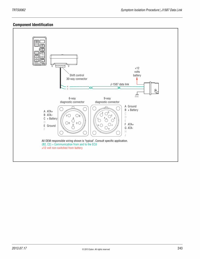
TRTS0062 Symptom Isolation Procedure | J1587 Data Link
Component Identification
VOLUMECONTROL
SERVICE
SHIFT
Eaton FullerTransmissions
L
H
D
N
R
+12volts
battery
J-1587 data linkB2
C2
GROUND
All OEM responsible wiring shown is "typical". Consult specific application.(B2, C2) = Communication from and to the ECU +12 volt non-switched from battery
6-waydiagnostic connector
A ATA+B ATA–C + BatteryDE GroundF
9-waydiagnostic connector
A GroundB + BatteryCDEF ATA+G ATA-HJ
Shift control30-way connector
AB
CD
E
FAF
J
E
G
H
DC
B
2013.07.17 © 2013 Eaton. All rights reserved 243

24
J1587 Data Link Test | Symptom Isolation Procedure TRTS0062
J1587 Data Link Test
1. Key off.
2. Measure voltage either between 6-way diagnostic connector Pin C and Pin E or 9-way diagnostic con-nector Pin B and Pin A.
• If voltage is within 0.6 volts of battery voltage, go to Step B.
• If voltage is outside of range, repair battery or ground line to vehicle diagnostic connector. Go to Step V.
1. Key off.
2. Disconnect negative battery cable.
3. Disconnect Vehicle Harness 30-way connector.
4. Measure resistance from Vehicle Harness 30-way connector Pin B2 and either 6-way diagnostic con-nector Pin A or 9-way diagnostic connector Pin F.
• If resistance is 0–0.3 ohms, go to Step C.
• If resistance is outside of range, repair Vehicle Harness. Repeat this step.
A Purpose: Measure battery voltage at the diagnos-tics connector.
VOLTS
V COM A
F
E
D
A
B
C
VOLTS
V COM A
AF
J
E
G
H
DC
B
B Purpose: Confirm continuity of the OEM J1587 Data link.
K
J
H
G
F
E
D
C
B
A
3 2 1
3 2 1
K
J
H
G
F
E
D
C
B
A
3 2 1
3 2 1
F
E
D
A
B
C
VOLTS
V COM A
VOLTS
V COM A
AF
J
E
G
H
DC
B
4 © 2013 Eaton. All rights reserved 2013.07.17

TRTS0062 Symptom Isolation Procedure | J1587 Data Link Test
1. Measure resistance between either 6-way diagnos-tic connector Pin A or 9-way diagnostic connector Pin F and ground.
• If resistance is more than 10K ohms or open circuit [OL], go to Step D.
• If resistance is less than 10K ohms, repair OEM harness. Go to Step V.
1. Measure resistance between Vehicle Harness 30-way connector Pin C2 and either 6-way diag-nostic connector Pin B or 9-way diagnostic con-nector Pin G.
• If resistance is 0–0.3 ohms, go to Step E.
• If resistance is outside of range, repair Vehicle Harness. Go to Step V.
C Purpose: Test for a short to ground on the J1587 Data Link.
OHMS
V COM A
F
E
D
A
B
C
GROUND
OHMS
V COM A
GROUND
AF
J
E
G
H
DC
B
D Purpose: Confirm continuity of the J1587 Data Link.
K
J
H
G
F
E
D
C
B
A
3 2 1
3 2 1
K
J
H
G
F
E
D
C
B
A
3 2 1
3 2 1
F
E
D
A
B
C
VOLTS
V COM A
VOLTS
V COM A
AF
J
E
G
H
DC
B
2013.07.17 © 2013 Eaton. All rights reserved 245

24
J1587 Data Link Test | Symptom Isolation Procedure TRTS0062
1. Measure resistance between either 6-way diagnos-tic connector Pin B or 9-way diagnostic connector Pin G and ground.
• If resistance is more than 10K ohms or open circuit [OL], go to Step V.
• If resistance is less than 10K ohms, repair OEM harness. Go to Step V.
1. Key on.
2. Connect PC-based Service Tool.
• If PC-based Service Tool functions correctly, test complete.
• If PC-based Service Tool does not function correctly, go to Step A. to find error in testing.
E Purpose: Test for a short to ground on the J1587 Data Link.
V Purpose: Verify repair.
OHMS
V COM A
F
E
D
A
B
C
GROUND
OHMS
V COM A
GROUND
AF
J
E
G
H
DC
B
6 © 2013 Eaton. All rights reserved 2013.07.17

TRTS0062 Symptom Isolation Procedure | J1587 Data Link Test
2013.07.17 © 2013 Eaton. All rights reserved 247

24
Range System Test | Symptom Isolation Procedure TRTS0062
Range System Test
OverviewThis symptom-driven test is completed if the transmission does not perform range shifts, and there are no Active or Inactive fault codes.
DetectionThe failure is observed by the driver when operating the vehicle. To observe this failure, operate the vehicle and make several shifts up and down across the range.
Conditions to Set Fault Code Active
FallbackThere is no fallback for this symptom.
Possible Causes This symptom can be caused by any of the following:
• Low air pressure
• Contaminated air supply
• Air leak
• Range Valve
• Range Synchronizer
• Range Actuator, Cylinder, Piston, Yoke
Additional Tools • Basic hand tools
• Two 0-100 PSI Air Pressure gauges
8 © 2013 Eaton. All rights reserved 2013.07.17
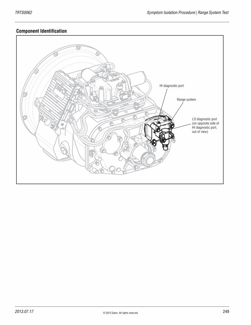
TRTS0062 Symptom Isolation Procedure | Range System Test
Component Identification
Range system
HI diagnostic port
LO diagnostic port (on opposite side of HI diagnostic port, out of view)
2013.07.17 © 2013 Eaton. All rights reserved 249

25
Range System Test | Symptom Isolation Procedure TRTS0062
Range System Test
1. Key off.
2. Install both 0-100 PSI air pressure gauges into the Range Valve diagnostic ports.
3. Start engine and allow air pressure to build to gov-ernor cut off.
4. Release clutch to register Input Shaft Speed in the transmission.
5. Turn off engine, but leave key on.
6. With the Shift Controller, select reverse, then select neutral.
• If LO range air pressure gauge is between 55–65 PSI and the HI range air pressure gauge is 0 PSI, go to Step B.
• If neither air pressure gauge reads as listed above, replace the Range Valve and Range Cylinder Cover as required. Repeat this step.
1. Key on.
2. With Shift Controller, select reverse, press the Upshift Button, then select neutral.
• If HI range air pressure gauge is between 55–65 PSI and the LO range air pressure gauge is at 0 PSI, repair range system as required. Go to Step V.
• If neither air pressure gauge reads as listed above, replace the Range Valve and Range Cylinder Cover as required. Go to Step V.
A Purpose: Measure LO range air pressure.
LO range0-100 PSI gauge
HI range0-100 PSI gauge
B Purpose: Measure HI range air pressure.
Note: If the gear display does not read "H" (10-Speed) or"IH" (18-Speed), go to the Up/Down Button Test.
LO range0-100 PSI gauge
HI range0-100 PSI gauge
10-Speed 18-Speed
or
0 © 2013 Eaton. All rights reserved 2013.07.17

TRTS0062 Symptom Isolation Procedure | Range System Test
1. Key off.
2. Remove gauges.
3. Key on.
4. Drive the vehicle to determine whether the com-plaint has been repaired.
• If complaint was repaired, test complete.
• If the complaint was not repaired, go to Step A. to find error in testing.
V Purpose: Verify repair.
2013.07.17 © 2013 Eaton. All rights reserved 251

25
Splitter System | Symptom Isolation Procedure TRTS0062
Splitter System
OverviewThis symptom-driven test is completed if the transmission does not perform Splitter Shifts, and there are no Active or Inactive fault codes.
DetectionThe failure is observed by the Operator when driving the vehicle. To observe this failure, drive the vehicle and make several shifts up and down across the Splitter.
Conditions to Set Fault Code Active
FallbackThere is no fallback for this symptom.
Possible Causes This symptom can be caused by any of the following:
• Low air pressure
• Contaminated air supply
• Air leak
• Splitter Valve
• Splitter Actuator, Cylinder, Piston, Yoke
Additional Tools • Basic hand tools
• Two 0–100 PSI Air Pressure gauges
2 © 2013 Eaton. All rights reserved 2013.07.17
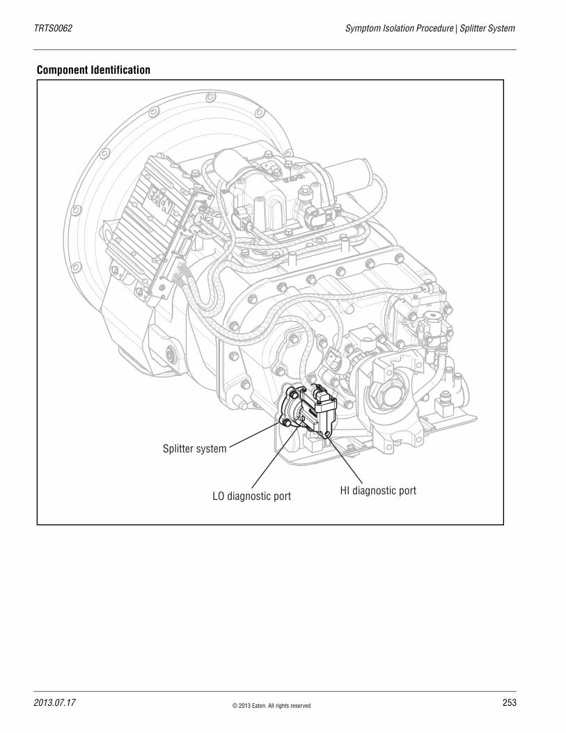
TRTS0062 Symptom Isolation Procedure | Splitter System
Component Identification
Splitter system
HI diagnostic portLO diagnostic port
2013.07.17 © 2013 Eaton. All rights reserved 253
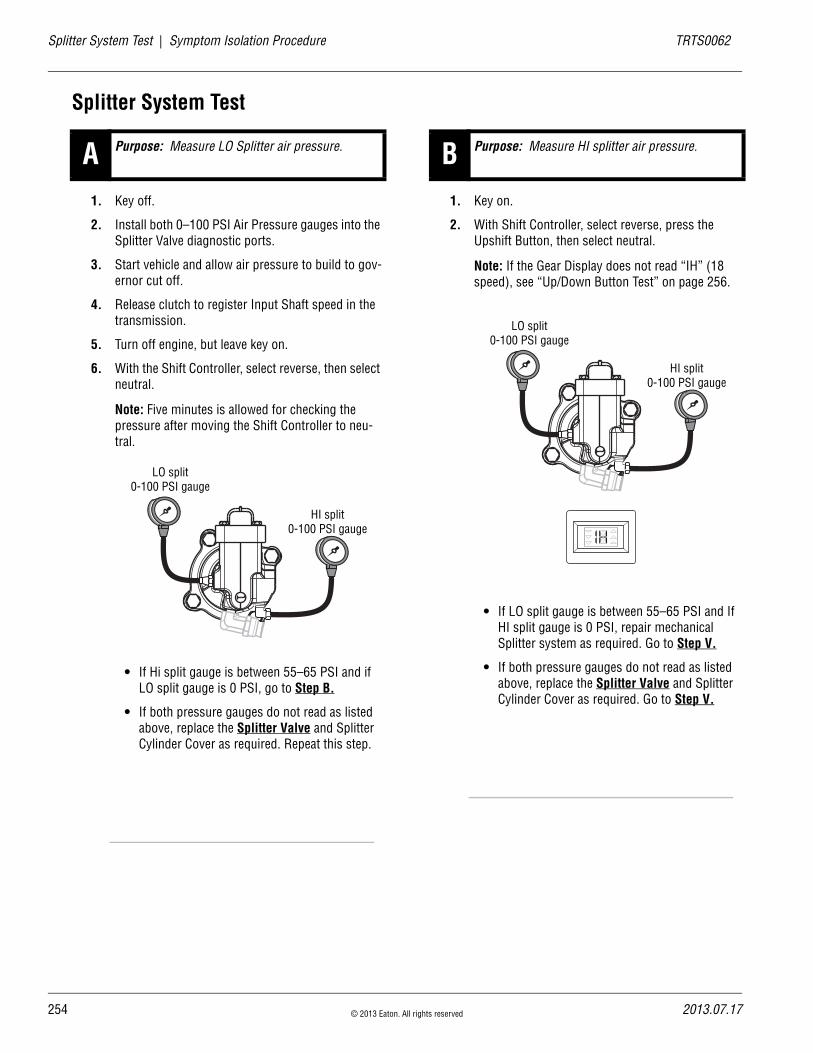
25
Splitter System Test | Symptom Isolation Procedure TRTS0062
Splitter System Test
1. Key off.
2. Install both 0–100 PSI Air Pressure gauges into the Splitter Valve diagnostic ports.
3. Start vehicle and allow air pressure to build to gov-ernor cut off.
4. Release clutch to register Input Shaft speed in the transmission.
5. Turn off engine, but leave key on.
6. With the Shift Controller, select reverse, then select neutral.
Note: Five minutes is allowed for checking the pressure after moving the Shift Controller to neu-tral.
• If Hi split gauge is between 55–65 PSI and if LO split gauge is 0 PSI, go to Step B.
• If both pressure gauges do not read as listed above, replace the Splitter Valve and Splitter Cylinder Cover as required. Repeat this step.
1. Key on.
2. With Shift Controller, select reverse, press the Upshift Button, then select neutral.
Note: If the Gear Display does not read “IH” (18 speed), see “Up/Down Button Test” on page 256.
• If LO split gauge is between 55–65 PSI and If HI split gauge is 0 PSI, repair mechanical Splitter system as required. Go to Step V.
• If both pressure gauges do not read as listed above, replace the Splitter Valve and Splitter Cylinder Cover as required. Go to Step V.
A Purpose: Measure LO Splitter air pressure.
LO split0-100 PSI gauge
HI split0-100 PSI gauge
B Purpose: Measure HI splitter air pressure.
LO split0-100 PSI gauge
HI split0-100 PSI gauge
4 © 2013 Eaton. All rights reserved 2013.07.17

TRTS0062 Symptom Isolation Procedure | Splitter System Test
1. Key off.
2. Remove all gauges.
3. Key on.
4. Drive the vehicle to determine whether the com-plaint has been repaired.
• If the complaint was repaired, test complete.
• If the complaint was not repaired, go to Step A. to find error in testing.
V Purpose: Verify repair.
2013.07.17 © 2013 Eaton. All rights reserved 255

25
Up/Down Button Test | Symptom Isolation Procedure TRTS0062
Up/Down Button Test
OverviewThis symptom-driven test is performed if unable to shift the transmission with the Up/Down Buttons, and there are no Active or Inactive codes.
DetectionThe Shift Controller has no fault detection capability for this failure. The failure is observed by the Operator when driving the vehicle.
Conditions to Set Fault Code Active
FallbackThere is no fallback for this symptom.
Possible Causes This symptom can be caused by any of the following:
• Shift Controller
Additional Tools • Basic hand tools
• Digital volt/ohm meter
6 © 2013 Eaton. All rights reserved 2013.07.17
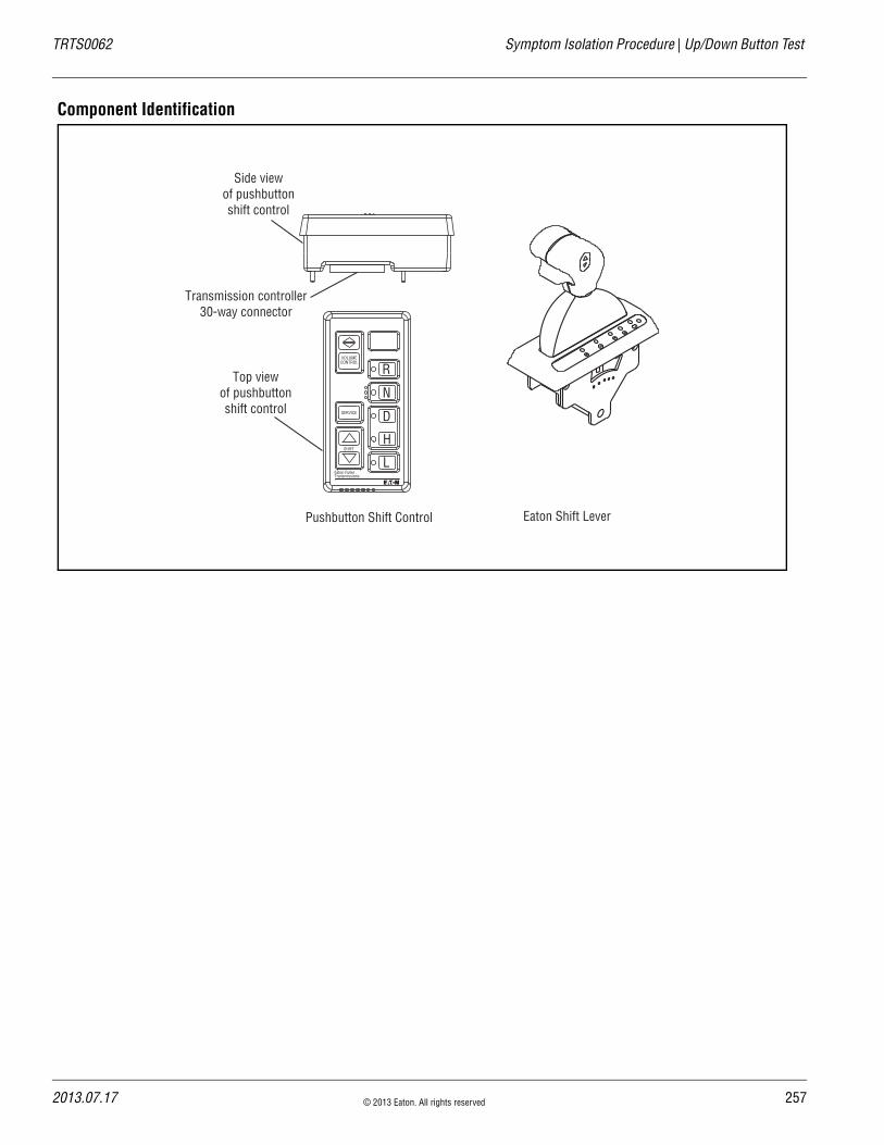
TRTS0062 Symptom Isolation Procedure | Up/Down Button Test
Component Identification
Top viewof pushbuttonshift control
Side viewof pushbuttonshift control
Pushbutton Shift Control
VOLUMECONTROL
SERVICE
SHIFT
Eaton FullerTransmissions
L
H
D
N
R
Transmission controller30-way connector
Eaton Shift Lever
2013.07.17 © 2013 Eaton. All rights reserved 257

25
Up/Down Button Test | Symptom Isolation Procedure TRTS0062
Up/Down Button Test
1. Start engine.
2. Place Shift Lever in manual.
3. Drive the vehicle and use the buttons to initiate up shifts and down shifts.
• If the up and down buttons are working prop-erly, the transmission will make up shifts and down shifts, test complete.
• If the transmission does not make up shifts or down shifts, replace Shift Control. Repeat this step.
A Purpose: Confirm operation of the Shift Controller up and down buttons.
8 © 2013 Eaton. All rights reserved 2013.07.17

TRTS0062 Symptom Isolation Procedure | Up/Down Button Test
2013.07.17 © 2013 Eaton. All rights reserved 259

26
UltraShift DM Shift Complaint | Symptom Isolation Procedure TRTS0062
UltraShift DM Shift Complaint
OverviewThis symptom-driven test is performed if a shift complaint exists, and there are no Active or Inactive codes.
DetectionThere is no detection other than a operator complaint.
Conditions to Set Fault Code Active
FallbackThere is no fallback mode for shift complaint; however, it may effect vehicle performance.
Possible Causes This symptom can be caused by any of the following:
• Inertia Brake
• Input Shaft Speed Sensor
• Electric Shifter
• Shift Bar Housing
• Transmission
Additional Tools • Basic hand tools
• Eaton Test Adapter kit
• PC-based Service Tool
0 © 2013 Eaton. All rights reserved 2013.07.17

TRTS0062 Symptom Isolation Procedure | UltraShift DM Shift Complaint
Component Identification
2013.07.17 © 2013 Eaton. All rights reserved 261
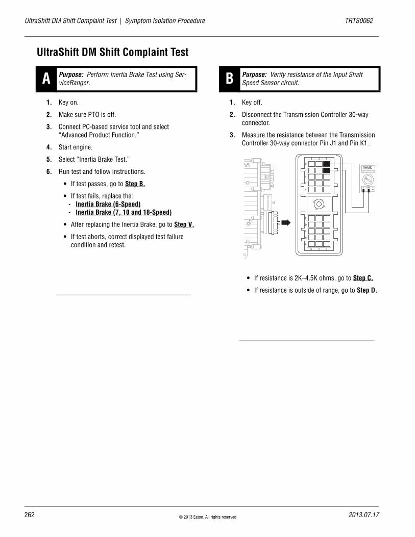
26
UltraShift DM Shift Complaint Test | Symptom Isolation Procedure TRTS0062
UltraShift DM Shift Complaint Test
1. Key on.
2. Make sure PTO is off.
3. Connect PC-based service tool and select “Advanced Product Function.”
4. Start engine.
5. Select “Inertia Brake Test.”
6. Run test and follow instructions.
• If test passes, go to Step B.
• If test fails, replace the:- Inertia Brake (6-Speed)- Inertia Brake (7, 10 and 18-Speed)
• After replacing the Inertia Brake, go to Step V.
• If test aborts, correct displayed test failure condition and retest.
1. Key off.
2. Disconnect the Transmission Controller 30-way connector.
3. Measure the resistance between the Transmission Controller 30-way connector Pin J1 and Pin K1.
• If resistance is 2K–4.5K ohms, go to Step C.
• If resistance is outside of range, go to Step D.
A Purpose: Perform Inertia Brake Test using Ser-viceRanger. B Purpose: Verify resistance of the Input Shaft
Speed Sensor circuit.
K
J
H
G
F
E
D
C
B
A
3 2 1
3 2 1
OHMS
V COM A
2 © 2013 Eaton. All rights reserved 2013.07.17

TRTS0062 Symptom Isolation Procedure | UltraShift DM Shift Complaint Test
1. Measure resistance between the Transmission Har-ness 30-way connector Pin J1 and ground.
• If resistance is more than 10K ohms or open circuit [OL], go to Step F.
• If resistance is less than 10K ohms, go to Step D.
1. Disconnect the Transmission Harness from the Input Shaft Speed Sensor.
2. Measure resistance between Input Shaft Speed Sensor Pin A and Pin B.
• If resistance is 2K–4.5K ohms, go to Step E.
• If resistance is outside of range, replace the:- Input Shaft Speed Sensor (6-Speed)- Input Shaft Speed Sensor (7, 10 and
18-Speed)
• After replacing Input Shaft Speed Sensor, go to Step V.
C Purpose: Test for a short to ground on the Input Shaft Speed Sensor circuit.
K
J
H
G
F
E
D
C
B
A
3 2 1
3 2 1
OHMS
V COM A
GROUND
D Purpose: Measure resistance of the Input Shaft Speed Sensor.
OHMS
V COM A
A B
2013.07.17 © 2013 Eaton. All rights reserved 263

26
UltraShift DM Shift Complaint Test | Symptom Isolation Procedure TRTS0062
1. Measure resistance between Input Shaft Speed Sensor Pin A and ground.
• If resistance is 10K ohms or open circuit [OL], Replace the Adapter Test Kit J43318. Go to Step V..
• If resistance is less than 10K ohms, replace the:
- Input Shaft Speed Sensor (6-Speed)- Input Shaft Speed Sensor (7, 10 and
18-Speed)
• After replacing the Input Shaft Speed Sensor, go to Step V.
1. Key off.
2. Inspect main power 2-way connector terminals, in-line fuse holder and power supply connections for integrity and corrosion.
• If no problem found, go to Step G.
• If problem is found, repair power/ground path for the main power supply. Go to Step V.
E Purpose: Test for a short to ground on the Input Shaft Speed Sensor.
OHMS
V COM A
A B
GROUND
F Purpose: Inspect the integrity of the Fuse Holder and connections.
A B
+–
+–
+–
+–
4 © 2013 Eaton. All rights reserved 2013.07.17

TRTS0062 Symptom Isolation Procedure | UltraShift DM Shift Complaint Test
1. Key off.
2. Insert 20-amp fuse into Motor Supply 2-way con-nector.
• If fuse blows immediately, go to Step H.
• If fuse does not blow immediately, repair wir-ing from the battery to the Transmission Con-troller. Go to Step V.
1. Key off.
2. Remove Electric Shifter from Shift Bar Housing.
3. Inspect the Shift Bar Housing Shift Blocks, Shift Rails and Electric Shifter for evidence of lube con-tamination.
• If no problem found, contact your Eaton Rep-resentative or call 1-800-826-HELP
• If problem found, repair as required. Go to Step V.
1. Key on.
2. Drive the vehicle to determine whether the com-plaint has been repaired.
• If shift complaint has been repaired, test com-plete.
• If the shift complaint has not been repaired, contact your Eaton Representative or call 1-800-826-HELP
G Purpose: Confirm the Vehicle Harness will carry a proper load.
H Purpose: Visually inspect the Shift Bar Housing, Electric Shifter and base transmission.
Main Power Supply 2-Way Connector20 Amp Fuse
30 Amp Fuse
V Purpose: Verify repair.
2013.07.17 © 2013 Eaton. All rights reserved 265

26
UltraShift ASW Shift Complaint | Symptom Isolation Procedure TRTS0062
UltraShift ASW Shift Complaint
OverviewThis symptom-driven test is performed if a shift complaint exists, and there are no Active or Inactive codes.
DetectionThere is no detection other than a Operator complaint.
Conditions to Set Fault Code Active
FallbackThere is no fallback mode for shift complaint; however, it may effect vehicle performance.
Possible Causes This symptom can be caused by any of the following:
• Low fluid level
• Inertia Brake
• Input Shaft Speed Sensor
• Electric Shifter
• Transmission
• Shift Bar Housing
Additional Tools • Basic hand tools
• Eaton Test Adapter Kit
• PC-based Service Tool
6 © 2013 Eaton. All rights reserved 2013.07.17

TRTS0062 Symptom Isolation Procedure | UltraShift ASW Shift Complaint
Component Identification
Electric shifter
Inertia brakeFluid
Clutch
Speed Sensor
2013.07.17 © 2013 Eaton. All rights reserved 267

26
UltraShift ASW Shift Complaint Test | Symptom Isolation Procedure TRTS0062
UltraShift ASW Shift Complaint Test
1. Place transmission in neutral.
2. Allow engine to idle at 600–700 RPM for a mini-mum of 2 minutes. Ensure transmission fluid tem-perature is 60 –120° F (16 to 49° C)
3. Check transmission fluid level.
• If fluid level is at Cold-Full mark, go to Step B.
• If fluid level is below the Cold-Add mark, cor-rect fluid level, check for leaks. Go to Step V.
1. Key on.
2. Make sure PTO is off.
3. Connect PC-based service tool and select “Advanced Product Function.”
4. Start engine.
5. Select “Inertia Brake Test.”
6. Run test and follow instructions.
• If test passes, go to Step C.
• If test fails, replace the:- Inertia Brake (6-Speed)- Inertia Brake (7, 10 and 18-Speed)
• After replacing the Inertia Brake, go to Step V.
• If test aborts, correct displayed test failure condition and retest.
1. Key off.
2. Disconnect the Transmission Controller 30-way connector.
3. Measure the resistance between the Transmission Controller 30-way connector Pin J1 and Pin K1.
• If resistance is 2K–4.5K ohms, go to Step D.
• If resistance is outside of range, go to Step E.
A Purpose: Check wet clutch fluid level.
B Purpose: Perform Inertia Brake Test using Ser-viceRanger.
C Purpose: Verify resistance of the Input Shaft Speed Sensor circuit.
K
J
H
G
F
E
D
C
B
A
3 2 1
3 2 1
OHMS
V COM A
8 © 2013 Eaton. All rights reserved 2013.07.17

TRTS0062 Symptom Isolation Procedure | UltraShift ASW Shift Complaint Test
1. Measure resistance between the Transmission Har-ness 30-way connector Pin J1 and ground.
• If resistance is more than 10K ohms or open circuit [OL], go to Step G.
• If resistance is less than 10K ohms, go to Step E.
1. Disconnect the Transmission Harness from the Input Shaft Speed Sensor.
2. Measure resistance between Input Shaft Speed Sensor Pin A and Pin B.
• If resistance is 2K–4.5K ohms, go to Step F.
• If resistance is outside of range, replace the:- Input Shaft Speed Sensor (6-Speed)- Input Shaft Speed Sensor (7, 10 and
18-Speed)
• After replacing the Input Shaft Speed Sensor, go to Step V.
D Purpose: Test for a short to ground on the Input Shaft Speed Sensor circuit.
K
J
H
G
F
E
D
C
B
A
3 2 1
3 2 1
OHMS
V COM A
GROUND
E Purpose: Measure resistance of the Input Shaft Speed Sensor.
OHMS
V COM A
A B
2013.07.17 © 2013 Eaton. All rights reserved 269

27
UltraShift ASW Shift Complaint Test | Symptom Isolation Procedure TRTS0062
1. Measure resistance between Input Shaft Speed Sensor Pin A and ground.
• If resistance is 10K ohms or open circuit [OL], replace the Transmission Harness. Go to Step V.
• If resistance is less than 10K ohms, replace the:
- Input Shaft Speed Sensor (6-Speed)- Input Shaft Speed Sensor (7, 10 and
18-Speed)
• After replacing the Input Shaft Speed Sensor, go to Step V.
1. Key off.
2. Inspect main power 2-way connector terminals, in-line fuse holder, and power supply connections for integrity and corrosion.
• If no problem found, go to Step H.
• If problem is found, repair power/ground path for the main power supply. Go to Step V.
F Purpose: Test for a short to ground on the Input Shaft Speed Sensor.
OHMS
V COM A
A B
GROUND
G Purpose: Inspect the integrity of the Fuse Holder.
A B
+–
+–
+–
+–
0 © 2013 Eaton. All rights reserved 2013.07.17

TRTS0062 Symptom Isolation Procedure | UltraShift ASW Shift Complaint Test
1. Key off.
2. Insert 20-amp fuse into Motor Supply 2-way con-nector.
• If fuse blows immediately, go to Step I.
• If fuse does not blow immediately, repair wir-ing from the battery to the Transmission Con-troller. Go to Step V.
1. Key off.
2. Remove Electric Shifter from Shift Bar Housing.
3. Inspect the Shift Bar Housing Shift Blocks, Shift Rails and Electric Shifter for evidence of lube con-tamination.
• If no problem found, contact your Eaton Rep-resentative or call 1-800-826-HELP.
• If problem found, repair as required. Go to Step V.
H Purpose: Confirm the Vehicle Harness will carry a proper load.
Main Power Supply 2-Way Connector20 Amp Fuse
30 Amp Fuse
I Purpose: Visually inspect the Shift Bar Housing, Electric Shifter and base transmission
2013.07.17 © 2013 Eaton. All rights reserved 271

27
UltraShift ASW Shift Complaint Test | Symptom Isolation Procedure TRTS0062
1. Key on.
2. Drive the vehicle to determine whether the com-plaint has been repaired.
• If shift complaint has been repaired, test com-plete.
• If the shift complaint has not been repaired, contact your Eaton Representative, or call 1-800-826-HELP.
V Purpose: Verify repair.
2 © 2013 Eaton. All rights reserved 2013.07.17

TRTS0062 Symptom Isolation Procedure | UltraShift ASW Shift Complaint Test
2013.07.17 © 2013 Eaton. All rights reserved 273

27
UltraShift ASW Clutch Engagement | Symptom Isolation Procedure TRTS0062
UltraShift ASW Clutch Engagement
OverviewThis symptom-driven test is performed if a clutch engage-ment complaint exists, and there are no Active or Inactive codes.
DetectionThere is no detection other than a Operator complaint.
Conditions to Set Fault Code Active
FallbackThere is no fallback mode for clutch engagement complaint; however, it may effect vehicle performance.
Possible Causes This symptom can be caused by any of the following:
• Low fluid level
• Inertia Brake
• Clutch calibration
• Transmission
Additional Tools • Basic hand tools
• PC-based Service Tool
4 © 2013 Eaton. All rights reserved 2013.07.17

TRTS0062 Symptom Isolation Procedure | UltraShift ASW Clutch Engagement
Component Identification
Electric shifter
Inertia brakeFluid
Clutch
Speed Sensor
2013.07.17 © 2013 Eaton. All rights reserved 275

27
UltraShift ASW Clutch Engagement Test | Symptom Isolation Procedure TRTS0062
UltraShift ASW Clutch Engagement Test
1. Place transmission in neutral.
2. Allow engine to idle at 600–700 RPM for a mini-mum of 2 minutes. Ensure transmission fluid tem-perature is 60–120° F (16–49° C)
3. Check transmission fluid level.
• If fluid level is at Cold-Full mark, go to Step B.
• If fluid level is below the Cold-Add mark, cor-rect fluid level, check for leaks. Drive Vehicle. If Clutch Engagement Complaint exist repeat Step A.
1. Key on.
2. Engine running, allow engine to reach operating temperature
3. Key off.
4. Start vehicle.
5. Allow vehicle to Idle in Neutral for a minimum of 2 minutes.
6. Drive vehicle.
• If clutch engagement complaint does not change, remove Flywheel Inspection Cover and inspect rubber coupler for damage or shear. If no damage observed, go to Step C. If dam-aged observed, service Torsional Coupler.
• If clutch engagement complaint is corrected, test complete.
1. Key off.
2. Disconnect Transmission Harness from the Inertia Brake.
3. Key on.
4. Drive vehicle (flashing Service light will exist).
• If clutch engagement complaint does not change, contact your Eaton Representative or call 1-800-826-HELP
• If clutch engagement complaint is corrected, replace the:
- Inertia Brake (6-Speed)- Inertia Brake (7, 10 and 18-Speed)
• After replacing the Inertia Brake, go to Step V.
A Purpose: Check wet clutch fluid level.
B Purpose: Complete a clutch calibration.
C Purpose: Confirm operation.
6 © 2013 Eaton. All rights reserved 2013.07.17

TRTS0062 Symptom Isolation Procedure | UltraShift ASW Clutch Engagement Test
1. Key off.
2. Reconnect Transmission Harness to Inertia Brake.
3. Key on.
4. Drive the vehicle to determine whether the com-plaint has been repaired.
• If shift complaint has not been repaired, con-tact your Eaton Representative or call 1-800-826-HELP
• If the shift complaint has been repaired, test complete.
V Purpose: Verify repair.
2013.07.17 © 2013 Eaton. All rights reserved 277

27
Transmission Air Leak | Symptom Isolation Procedure TRTS0062
Transmission Air Leak
OverviewThis symptom-driven test is performed if the transmission has an air leak and there are no Active or Inactive fault codes.
DetectionThere is no detection process specifically for a transmission air leak; however, failures of this type are generally detected by the transmission or Operator as some other type of fault code or symptom.
Conditions to Set Fault Code Active
FallbackThere is no fallback mode for a transmission air leak; how-ever, it may effect other vehicle systems.
Possible Causes This symptom can be caused by any of the following:
• Contaminated air
• Range Valve
• Splitter Valve
• Air Filter/Regulator
• Range Piston / O-ring
• Splitter Piston / O-ring
Additional Tools • Basic hand tools
8 © 2013 Eaton. All rights reserved 2013.07.17
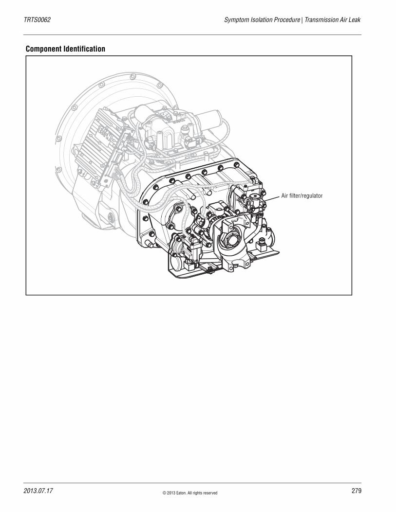
TRTS0062 Symptom Isolation Procedure | Transmission Air Leak
Component Identification
Air filter/regulator
2013.07.17 © 2013 Eaton. All rights reserved 279

28
Transmission Air Leak Test | Symptom Isolation Procedure TRTS0062
Transmission Air Leak Test
1. Start engine.
2. Allow air pressure to build to governor cut off.
3. Leave transmission in neutral.
4. Key off.
5. Listen for constant air leaks.
• If there are no constant air leaks, go to Step B.
• If air leaks from fittings or air lines at:- Air filter/regulator- Splitter Cylinder supply line (18-speed only)
Repair fittings or lines as required. After mak-ing repairs, repeat this step.
• If air leaks at the Range Valve exhaust port, replace the Range Valve. Go to Step V.
• If air leaks at Splitter Valve exhaust port (18-speed only), replace the Splitter Valve. Go to Step V.
1. Start engine.
2. Turn off engine, but leave key in “ON” position.
3. With the Shift Controller, select reverse, then select neutral.
• If there are no constant air leaks, go to Step C.
• If air leaks at the Range Valve exhaust port, go to Step D.
• If air leaks at the Splitter Valve exhaust port (18-speed only), go to Step F.
• If air leaks at the Transmission Breather, go to Step G.
A Purpose: Confirm air leak B Purpose: Confirm location of air leak.
0 © 2013 Eaton. All rights reserved 2013.07.17
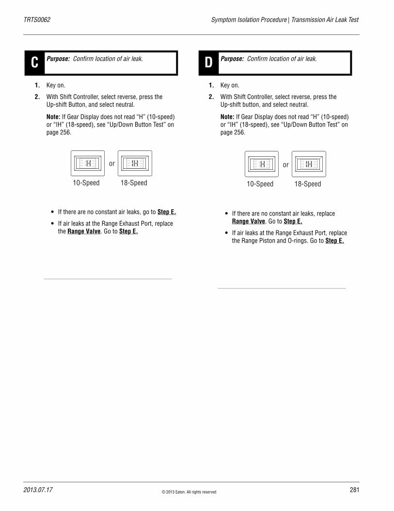
TRTS0062 Symptom Isolation Procedure | Transmission Air Leak Test
1. Key on.
2. With Shift Controller, select reverse, press the Up-shift Button, and select neutral.
Note: If Gear Display does not read “H” (10-speed) or “IH” (18-speed), see “Up/Down Button Test” on page 256.
• If there are no constant air leaks, go to Step E.
• If air leaks at the Range Exhaust Port, replace the Range Valve. Go to Step E.
1. Key on.
2. With Shift Controller, select reverse, press the Up-shift button, and select neutral.
Note: If Gear Display does not read “H” (10-speed) or “IH” (18-speed), see “Up/Down Button Test” on page 256.
• If there are no constant air leaks, replace Range Valve. Go to Step E.
• If air leaks at the Range Exhaust Port, replace the Range Piston and O-rings. Go to Step E.
C Purpose: Confirm location of air leak.
10-Speed 18-Speed
or
D Purpose: Confirm location of air leak.
10-Speed 18-Speed
or
2013.07.17 © 2013 Eaton. All rights reserved 281

28
Transmission Air Leak Test | Symptom Isolation Procedure TRTS0062
1. Key on.
2. With Shift Controller, select reverse, press the Down-shift button, and select neutral.
3. Listen for constant air leaks.
Note: If Gear Display does not read “R” (10-speed), see “Up/Down Button Test” on page 256.
• If there are no constant air leaks, test com-plete.
• If air leaks at the Splitter exhaust port, repair Splitter Piston and O-rings. Go to Step V.
1. Key on.
2. With Shift Controller, select reverse, press the Down-shift button, and select neutral.
3. Listen for constant air leaks.
Note: If Gear Display does not read “IR” (18-speed), see “Up/Down Button Test” on page 256.
• If there are no constant air leaks (18-speed only), replace the Splitter Valve Go to Step V.
• If air leaks at the Splitter Valve exhaust port, repair Splitter Piston and O-rings (18-speed only). Go to Step V.
E Purpose: Confirm location of air leak. F Purpose: Confirm location of air leak.
2 © 2013 Eaton. All rights reserved 2013.07.17

TRTS0062 Symptom Isolation Procedure | Transmission Air Leak Test
1. Key on.
2. With Shift Controller, select reverse, press the Down-shift button, and select neutral.
3. Listen for constant air leak.
Note: If Gear Display does not read “H” (10-speed) or “IH” (18-speed), see “Up/Down Button Test” on page 256.
• If the leak continues, repair the Range Yoke Bar O-rings as required (18-speed only). Go to Step V.
• If the air leak stops, replace the Splitter Yoke Bar O-ring as required (18-speed only. Go to Step V.
1. Start engine
2. Release clutch to register Input Shaft speed in the transmission.
3. Turn off engine, but leave key on.
4. Listen for constant air leaks under the following conditions:- With Shift Controller, select reverse, then select
neutral- With Shift Controller, select reverse, press
Upshift Button, then select neutral
• If there are no constant leaks, test complete.
• If there are constant air leaks, go to Step A. to find error in testing.
G Purpose: Confirm location of air leak.
10-Speed 18-Speed
or
V Purpose: Verify repair.
2013.07.17 © 2013 Eaton. All rights reserved 283

28
Shift Lever Back Light | Symptom Isolation Procedure TRTS0062
Shift Lever Back Light
OverviewThis symptom-driven test is performed if the Shift Lever or Shift Controller back lighting is not functioning.
DetectionThere is no detection other than an Operator complaint.
Conditions to Set Fault Code Active
FallbackThere is no fallback mode for this symptom.
Possible Causes This symptom can be caused by any of the following:
• OEM Wiring
• Shift Controller
• Shift Lever
Additional Tools • Basic hand tools
• Eaton Test Adapter kit
• Digital volt/ohm meter
4 © 2013 Eaton. All rights reserved 2013.07.17
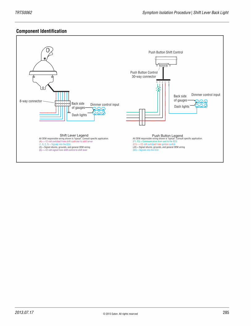
TRTS0062 Symptom Isolation Procedure | Shift Lever Back Light
Component Identification
Back side of gauges
Dash lights
Dimmer control input4 1 8 2 6 5 3
4 1 8 2 6 5 3
8-way connector
Push Button Shift Control
Push Button Control30-way connector
F2 F1 J3 C1 B3
Back side of gauges
Dash lights
Dimmer control input
All OEM responsible wiring shown is "typical". Consult specific application.(4) = +12 volt switched from shift controler to shift lerver(1, 8, 2, 5) = Signals into the ECU(3) = Signal returns, grounds, and general OEM wiring(6) = +12 volt signal from shift control to shift lever
All OEM responsible wiring shown is "typical". Consult specific application.(F1, F2) = Communication from and to the ECU(C1) = +12 volt switched from ignition switch(J3) = Signal returns, grounds, and general OEM wiring(B3) = Signals into the ECU
Shift Lever Legend Push Button Legend
2013.07.17 © 2013 Eaton. All rights reserved 285

28
Shift Lever Back Light Test | Symptom Isolation Procedure TRTS0062
Shift Lever Back Light Test
1. Is vehicle equipped with an Eaton Cobra Lever?
• If vehicle is not equipped with a Eaton Cobra Lever, go to Step B.
• If vehicle is equipped with a Eaton Cobra Lever, go to Step C.
1. Key off.
2. Disconnect Shift Controller 30-way connector.
3. Key on.
4. Measure voltage between Shift Controller Pin B3 and Pin J3 with the Dash lights fully on.
• If voltage is within 2 volts of battery voltage, replace the Shift Control Go to Step V.
• If voltage is outside of range, repair Vehicle Harness. Go to Step V.
1. Key off.
2. Disconnect Shift Lever 8-way connector.
3. Key on.
4. Measure voltage between Shift Lever 8-way Pin 4 and Pin 3.
• If voltage is within 1 volt of battery voltage, go to Step D.
• If voltage is outside of range, repair the igni-tion supply to the Eaton Cobra Lever. Go to Step V.
1. Key on.
2. Measure voltage between Shift Lever 8-way con-nector Pin 5 and Pin 3 with the Dash lights fully on.
• If voltage is within 2 volts of battery voltage, replace Eaton Cobra Lever. Go to Step V.
• If voltage is outside of range, repair Vehicle Harness to Eaton Cobra Lever. Go to Step V.
A Purpose: Visually identify if the vehicle is equipped with an Eaton Cobra Lever.
B Purpose: Measure battery voltage of the OEM Dash Light circuit.
C Purpose: Measure battery voltage of the OEM Dash Light circuit.
D Purpose: Measure battery voltage of the OEM Dash Light circuit.
6 © 2013 Eaton. All rights reserved 2013.07.17

TRTS0062 Symptom Isolation Procedure | Shift Lever Back Light Test
1. Key off.
2. Reconnect all connectors.
3. Key on.
4. Turn on the Dash lights fully.
• If back light works correctly, test complete.
• If back lights do not work correctly, go to Step A. to find error in testing.
V Purpose: Verify repair.
2013.07.17 © 2013 Eaton. All rights reserved 287

28
Connector Pin Descriptions | Appendix TRTS0062
Connector Pin Descriptions
Transmission Controller 18-Way (Vehicle Interface Connector)
18-Way Description Notes
A1 Batt 1
A2 ATA +
A3 GND 1
B1 Trans Batt 1
B2 ATA -
B3 GND 2
C1 EPL +
C2 EPL -
C3 EPL shield
D1 Aux speed 1 +
D2 Aux speed 1 -
D3 Aux input 2 Input, LO side
E1 Batt 2
E2 Trans Batt 2
E3 Aux input 2 (Return)
F1 Aux input 1 Input, LO side
F2 Aux input 1 (Return)
F3 Aux output 1 Output, LO side driver
8 © 2013 Eaton. All rights reserved 2013.07.17

TRTS0062 Appendix | Connector Pin Descriptions
Transmission Controller 30-Way Connector
30-Way Description Notes
A1 Rail position +
A2 Rail position (Signal)
A3 Rail position -
B1 Gear position +
B2 Gear position (Signal)
B3 Gear position -
C1 Aux Input 7 (Return)
C2 Aux Input 7 Input, LO side
C3 Aux analog Input 8 Input, Analog
D1 Output Shaft Speed +
D2 Output Shaft Speed -
D3 Aux Analog Input 9 Input, Analog
E1 Main Shaft Speed +
E2 Main Shaft Speed -
E3 Aux Analog Power (+5 volts)
F1 Range Valve High
F2 Range Valve Low
F3 Range Valve common
G1 Splitter Valve DIR
G2 Splitter Valve IND Output, High side driver
G3 Splitter Valve common Output, LO side driver
H1 Inertia Brake +
H2 Inertia Brake -
H3 Aux Analog (Return)
J1 Input Shaft Speed +
J2 Lock-up Clutch +
J3 Lock-up Clutch -
K1 Input Shaft Speed -
2013.07.17 © 2013 Eaton. All rights reserved 289

29
Connector Pin Descriptions | Appendix TRTS0062
K2 Interrupt Clutch +
K3 Interrupt Clutch -
30-Way Description Notes
0 © 2013 Eaton. All rights reserved 2013.07.17
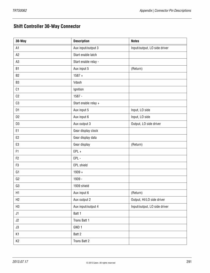
TRTS0062 Appendix | Connector Pin Descriptions
Shift Controller 30-Way Connector
30-Way Description Notes
A1 Aux input/output 3 Input/output, LO side driver
A2 Start enable latch
A3 Start enable relay -
B1 Aux input 5 (Return)
B2 1587 +
B3 Vdash
C1 Ignition
C2 1587 -
C3 Start enable relay +
D1 Aux input 5 Input, LO side
D2 Aux input 6 Input, LO side
D3 Aux output 3 Output, LO side driver
E1 Gear display clock
E2 Gear display data
E3 Gear display (Return)
F1 EPL +
F2 EPL -
F3 EPL shield
G1 1939 +
G2 1939 -
G3 1939 shield
H1 Aux input 6 (Return)
H2 Aux output 2 Output, HI/LO side driver
H3 Aux input/output 4 Input/output, LO side driver
J1 Batt 1
J2 Trans Batt 1
J3 GND 1
K1 Batt 2
K2 Trans Batt 2
2013.07.17 © 2013 Eaton. All rights reserved 291
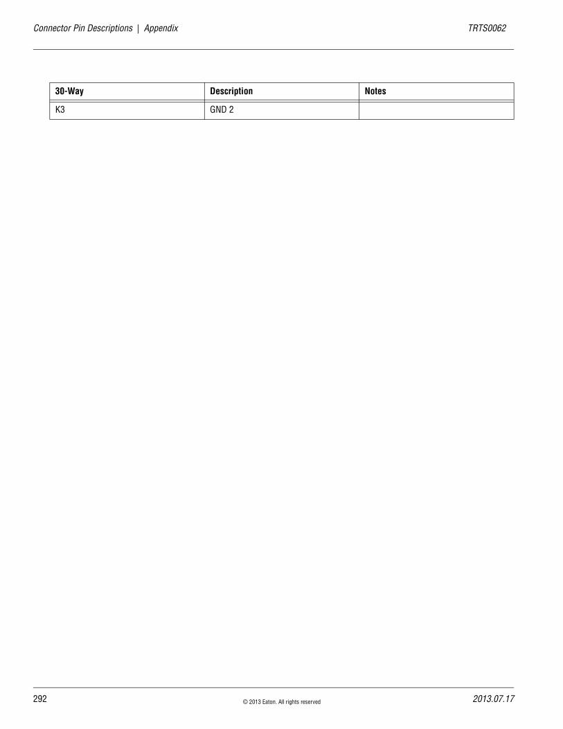
29
Connector Pin Descriptions | Appendix TRTS0062
K3 GND 2
30-Way Description Notes
2 © 2013 Eaton. All rights reserved 2013.07.17

TRTS0062 Appendix | Connector Pin Descriptions
2013.07.17 © 2013 Eaton. All rights reserved 293
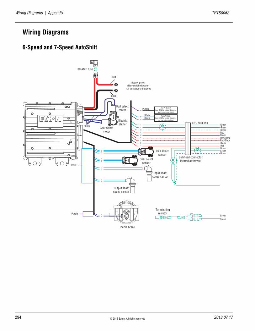
29
Wiring Diagrams | Appendix TRTS0062
Wiring Diagrams
6-Speed and 7-Speed AutoShift
A
B
A
B
Rail selectsensor
Gear selectsensor
Input shaft speed sensor
Output shaftspeed sensor
Inertia brake
A
B
30 AMP fuse
A1A2A3
B1B2B3
J1K1
D1D2
H1H2
C1
C2
C3
A1
A3
B1
E2
B3
E1
Terminatingresistor
J1
J2
J3
A
B
C
A
B
C
EPL data link
Bulkhead connectorlocated at firewall
Gear selectmotor
Rail selectmotor
Electricshifter
Aux #1 Output(see OEM for wiring diagrams
and correct operation)
Aux #1 Input(see OEM for wiring diagrams
and correct operation)
F3
F1
F2
Red
Black
Purple
Purple
WhiteBlack
GreenGreenGreen
GreenGreenGreen
Red
Red
Red/BlackRed/Black
Black
Black
White
PurpleGreenGreen
Battery power(Non-switched power)
run to starter or batteries
4 © 2013 Eaton. All rights reserved 2013.07.17
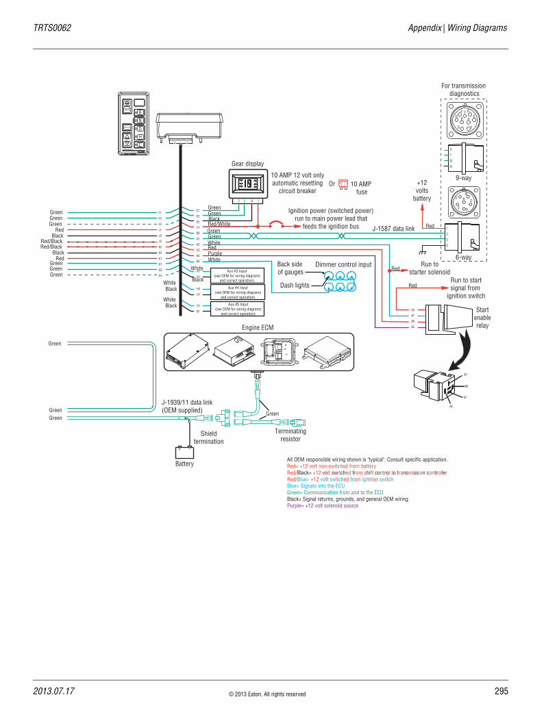
TRTS0062 Appendix | Wiring Diagrams
F1
F2
F3
J1
J3
J2
K2
K3
K1
G1
G2
G3
Terminatingresistor
J-1939/11 data link(OEM supplied)
Battery
+ _
Shieldtermination
Engine ECM
All OEM responsible wiring shown is "typical". Consult specific application.Red= +12 volt non-switched from batteryRed/Black= +12 volt switched from shift control to transmission controllerRed/Blue= +12 volt switched from ignition switchBlue= Signals into the ECUGreen= Communication from and to the ECUBlack= Signal returns, grounds, and general OEM wiringPurple= +12 volt solenoid source
Gear display
123 4
Back side of gauges
Dash lights
Dimmer control input
CABE
+12volts
battery
For transmission diagnostics
Startenablerelay
Run to startsignal from
ignition switch
Run tostarter solenoid
Ignition power (switched power)run to main power lead that
feeds the ignition bus
10 AMP 12 volt onlyautomatic resetting
circuit breaker10 AMP
fuseOr
AB
C
DE
F
J-1587 data link
E1
E2
E3
C1
B2
C2
A2
C3
A3
B3
30
87
86
85
30
86
87
85
BFGA
J C D
B A
G
H E
F
6-way
9-way
Aux #5 Input(see OEM for wiring diagrams
and correct operation)
Aux #4 Input(see OEM for wiring diagrams
and correct operation)
Aux #3 Input(see OEM for wiring diagrams
and correct operation)
H3
H1
A1
H1
D1
B1
VOLUMECONTROL
SERVICE
SHIFT
EATON FULLERTRANSMISSIONS
L
H
D
N
R
GreenGreen
Green
Green
Green
GreenGreenGreen
GreenGreen
Red
Red/Black
Red
Red/Black
Black
Black
GreenGreen
GreenGreen
BlackRed/White
White
White
RedPurple
Black
Black
Black
White
White
White Red
Red
Red
2013.07.17 © 2013 Eaton. All rights reserved 295
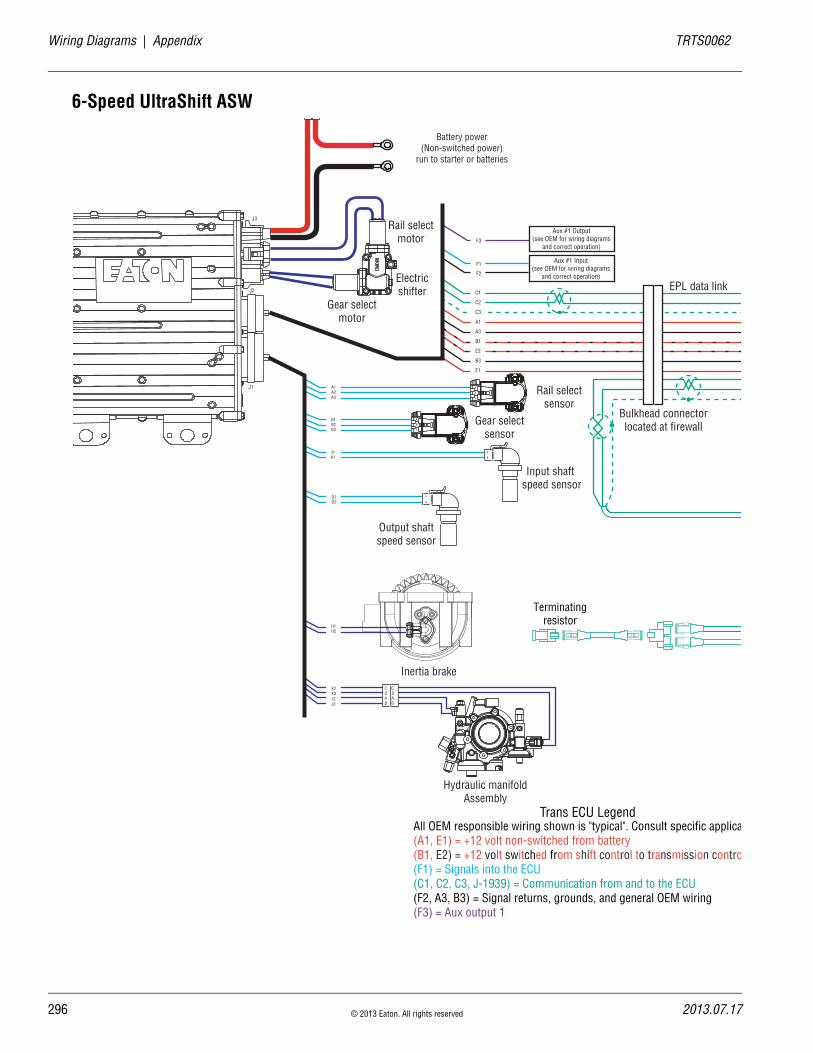
29
Wiring Diagrams | Appendix TRTS0062
6-Speed UltraShift ASW
A
B
A
B
Rail selectsensor
Gear selectsensor
Input shaft speed sensor
Output shaftspeed sensor
Inertia brake
A
B
A1A2A3
B1B2B3
J1K1
D1D2
H1H2
C1
C2
C3
A1
A3
B1
E2
B3
E1
Terminatingresistor
J1
J2
J3
A
B
C
A
B
C
EPL data link
Bulkhead connectorlocated at firewall
Gear selectmotor
Rail selectmotor
Electricshifter
Aux #1 Output(see OEM for wiring diagrams
and correct operation)
Aux #1 Input(see OEM for wiring diagrams
and correct operation)
F3
F1
F2
Hydraulic manifoldAssembly
C CD DA AB B
K2K3J2J3
Battery power(Non-switched power)
run to starter or batteries
All OEM responsible wiring shown is "typical". Consult specific applica(A1, E1) = +12 volt non-switched from battery(B1, E2) = +12 volt switched from shift control to transmission contro(F1) = Signals into the ECU(C1, C2, C3, J-1939) = Communication from and to the ECU(F2, A3, B3) = Signal returns, grounds, and general OEM wiring(F3) = Aux output 1
Trans ECU Legend
6 © 2013 Eaton. All rights reserved 2013.07.17

TRTS0062 Appendix | Wiring Diagrams
F1
F2
F3
J1
J3
J2
K2
K3
K1
G1
G2
G3
Terminatingresistor
J-1939/11 data link(OEM supplied)
Battery
+ _
Shieldtermination
Engine ECM
All OEM responsible wiring shown is "typical". Consult specific application.(J1, K1, 30, Run to Solenoid) = +12 volt non-switched from battery(J2, K2) = +12 volt switched from shift control to transmission controller(C1) = +12 volt switched from ignition switch(A2-87, B3, A1, H3, D1) = Signals into the ECU(F1, F2, F3, G1, G2, G3, E1, E2, B2, C2, J-1939) = Communication from and to the ECU(J3, K3, E3, H1, B1) = Signal returns, grounds, and general OEM wiring(A3-85) = -12 volt relay source(C3-86) = +12 volt relay source
Gear display
123 4
Back side of gauges
Dash lights
Dimmer control input
CABE
+12volts
battery
For transmission diagnostics
Startenablerelay
Run to startsignal from
ignition switch
Run tostarter solenoid
Ignition power (switched power)run to main power lead that
feeds the ignition bus
10 AMP 12 volt onlyautomatic resetting
circuit breaker10 AMP
fuseOr
AB
C
DE
F
J-1587 data link
E1
E2
E3
C1
B2
C2
A2
C3
A3
B3
30
87
86
85
30
86
87
85
BFGA
J C D
B A
G
H E
F
6-way
9-way
Aux #5 Input(see OEM for wiring diagrams
and correct operation)
Aux #4 Input(see OEM for wiring diagrams
and correct operation)
Aux #3 Input(see OEM for wiring diagrams
and correct operation)
H3
H1
A1
H1
D1
B1
VOLUMECONTROL
SERVICE
SHIFT
EATON FULLERTRANSMISSIONS
L
H
D
N
R
Shift Control ECU Legend
2013.07.17 © 2013 Eaton. All rights reserved 297

29
Wiring Diagrams | Appendix TRTS0062
10-Speed AutoShift
A
B
A
B
Rail selectsensor
Gear selectsensor
Input shaft speed sensor
Output shaftspeed sensor
A
B
30 AMP fuse
A1A2A3
B1B2B3
J1K1
D1D2
H1H2
C1
C2
C3
A1
A3
B1
E2
B3
E1
Terminatingresistor
J1
J2
J3
A
B
C
A
B
C
EPL data link
Bulkhead connectorlocated at firewall
Gear selectmotor
Rail selectmotor
Electricshifter
Aux #1 Output(see OEM for wiring diagrams
and correct operation)
Aux #1 Input(see OEM for wiring diagrams
and correct operation)
F3
F1
F2
Inertia brake (Optional)
C
B
A
Rangevalve
F3F2F1
Battery power(Non-switched power)
run to starter or batteries
All OEM responsible wiring shown is "typical". Consult specific application.(A1, E1) = +12 volt non-switched from battery(B1, E2) = +12 volt switched from shift control to transmission controller(F1) = Signals into the ECU(C1, C2, C3, J-1939) = Communication from and to the ECU(F2, A3, B3) = Signal returns, grounds, and general OEM wiring(F3) = Aux output 1
Trans ECU Legend
8 © 2013 Eaton. All rights reserved 2013.07.17
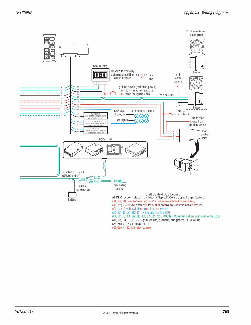
TRTS0062 Appendix | Wiring Diagrams
F1
F2
F3
J1
J3
J2
K2
K3
K1
G1
G2
G3
Terminatingresistor
J-1939/11 data link(OEM supplied)
Battery
+ _
Shieldtermination
Engine ECM
All OEM responsible wiring shown is "typical". Consult specific application.(J1, K1, 30, Run to Solenoid) = +12 volt non-switched from battery(J2, K2) = +12 volt switched from shift control to transmission controller(C1) = +12 volt switched from ignition switch(A2-87, B3, A1, H3, D1) = Signals into the ECU(F1, F2, F3, G1, G2, G3, E1, E2, B2, C2, J-1939) = Communication from and to the ECU(J3, K3, E3, H1, B1) = Signal returns, grounds, and general OEM wiring(A3-85) = -12 volt relay source(C3-86) = +12 volt relay source
Gear display
123 4
Back side of gauges
Dash lights
Dimmer control input
CABE
+12volts
battery
For transmission diagnostics
Startenablerelay
Run to startsignal from
ignition switch
Run tostarter solenoid
Ignition power (switched power)run to main power lead that
feeds the ignition bus
10 AMP 12 volt onlyautomatic resetting
circuit breaker10 AMP
fuseOr
AB
C
DE
F
J-1587 data link
E1
E2
E3
C1
B2
C2
A2
C3
A3
B3
30
87
86
85
30
86
87
85
BFGA
J C D
B A
G
H E
F
6-way
9-way
Aux #5 Input(see OEM for wiring diagrams
and correct operation)
Aux #4 Input(see OEM for wiring diagrams
and correct operation)
Aux #3 Input(see OEM for wiring diagrams
and correct operation)
H3
H1
A1
H1
D1
B1
VOLUMECONTROL
SERVICE
SHIFT
EATON FULLERTRANSMISSIONS
L
H
D
N
R
Shift Control ECU Legend
2013.07.17 © 2013 Eaton. All rights reserved 299

30
Wiring Diagrams | Appendix TRTS0062
10-Speed UltraShift DM
A
B
A
B
Rail selectsensor
Gear selectsensor
Input shaft speed sensor
Output shaftspeed sensor
A
B
30 AMP fuse
A1A2A3
B1B2B3
J1K1
D1D2
H1H2
C1
C2
C3
A1
A3
B1
E2
B3
E1
Terminatingresistor
J1
J2
J3
A
B
C
A
B
C
EPL data link
Bulkhead connectorlocated at firewall
Gear selectmotor
Rail selectmotor
Electricshifter
Aux #1 Output(see OEM for wiring diagrams
and correct operation)
Aux #1 Input(see OEM for wiring diagrams
and correct operation)
F3
F1
F2
Inertia brake
C
B
A
Rangevalve
F3F2F1
Battery power(Non-switched power)
run to starter or batteries
All OEM responsible wiring shown is "typical". Consult specific application.(A1, E1) = +12 volt non-switched from battery(B1, E2) = +12 volt switched from shift control to transmission controller(F1) = Signals into the ECU(C1, C2, C3, J-1939) = Communication from and to the ECU(F2, A3, B3) = Signal returns, grounds, and general OEM wiring(F3) = Aux output 1
Trans ECU Legend
0 © 2013 Eaton. All rights reserved 2013.07.17
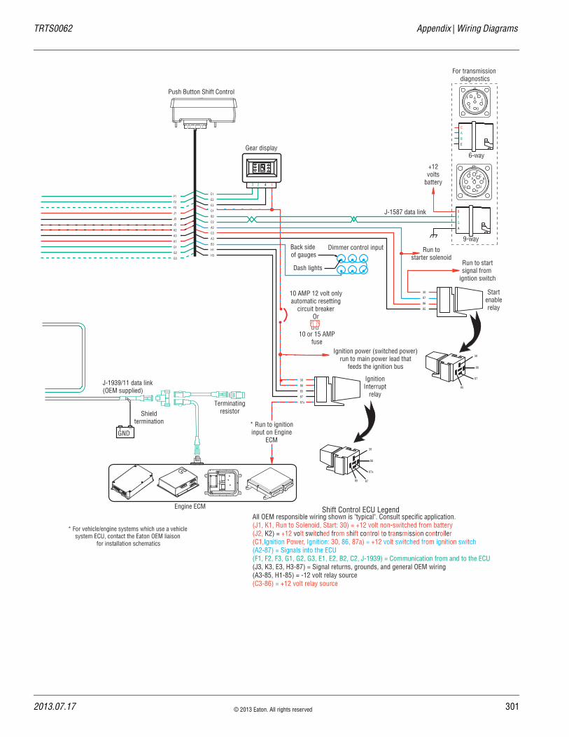
TRTS0062 Appendix | Wiring Diagrams
J-1939/11 data link(OEM supplied)
GND+ _
Shieldtermination
Gear display
123 4
Back side of gauges
Dash lights
Dimmer control input
CABE
+12volts
battery
For transmission diagnostics
Startenablerelay
Run to startsignal from
igntion switch
Run tostarter solenoid
Ignition power (switched power)run to main power lead that
feeds the ignition bus
10 AMP 12 volt onlyautomatic resetting
circuit breakerOr
10 or 15 AMPfuse
AB
C
DE
F
J-1587 data link
30
87
86
85
30
86
87
85
BFGA
6-way
9-way
F1
F2
F3
J1
J3
J2
K2
K3
K1
G1
G2
G3
Push Button Shift Control
IgnitionInterrupt
relay
30
86
87a
85
Engine ECM
Terminatingresistor
* Run to ignitioninput on Engine
ECM
AF
J
E
GH
DC
B
30
86
85
87
87a
E1
E2
E3
C1
B2
C2
A2
C3
A3
B3
H1
H3
87
* For vehicle/engine systems which use a vehiclesystem ECU, contact the Eaton OEM liaison
for installation schematics
All OEM responsible wiring shown is "typical". Consult specific application.(J1, K1, Run to Solenoid, Start: 30) = +12 volt non-switched from battery(J2, K2) = +12 volt switched from shift control to transmission controller(C1,Ignition Power, Ignition: 30, 86, 87a) = +12 volt switched from ignition switch(A2-87) = Signals into the ECU(F1, F2, F3, G1, G2, G3, E1, E2, B2, C2, J-1939) = Communication from and to the ECU(J3, K3, E3, H3-87) = Signal returns, grounds, and general OEM wiring(A3-85, H1-85) = -12 volt relay source(C3-86) = +12 volt relay source
Shift Control ECU Legend
2013.07.17 © 2013 Eaton. All rights reserved 301

30
Wiring Diagrams | Appendix TRTS0062
18-Speed AutoShift
A
B
A
B
Rail selectsensor
Gear selectsensor
Input shaft speed sensor
Output shaftspeed sensor
A
B
30 AMP fuse
A1A2A3
B1B2B3
J1K1
D1D2
H1H2
C1
C2
C3
A1
A3
B1
E2
B3
E1
Terminatingresistor
J1
J2
J3
A
B
C
A
B
C
EPL data link
Bulkhead connectorlocated at firewall
Gear selectmotor
Rail selectmotor
Electricshifter
Aux #1 Output(see OEM for wiring diagrams
and correct operation)
Aux #1 Input(see OEM for wiring diagrams
and correct operation)
F3
F1
F2
Inertia brake (Optional)
C
B
A
Rangevalve
F3F2F1
C
B
A
Splittervalve
G3G2G1
Battery power(Non-switched power)
run to starter or batteries
All OEM responsible wiring shown is "typical". Consult specific application.(A1, E1) = +12 volt non-switched from battery(B1, E2) = +12 volt switched from shift control to transmission controller(F1) = Signals into the ECU(C1, C2, C3, J-1939) = Communication from and to the ECU(F2, A3, B3) = Signal returns, grounds, and general OEM wiring(F3) = Aux output 1
Trans ECU Legend
2 © 2013 Eaton. All rights reserved 2013.07.17

TRTS0062 Appendix | Wiring Diagrams
F1
F2
F3
J1
J3
J2
K2
K3
K1
G1
G2
G3
Terminatingresistor
J-1939/11 data link(OEM supplied)
Battery
+ _
Shieldtermination
Engine ECM
All OEM responsible wiring shown is "typical". Consult specific application.(J1, K1, 30, Run to Solenoid) = +12 volt non-switched from battery(J2, K2) = +12 volt switched from shift control to transmission controller(C1) = +12 volt switched from ignition switch(A2-87, B3, A1, H3, D1) = Signals into the ECU(F1, F2, F3, G1, G2, G3, E1, E2, B2, C2, J-1939) = Communication from and to the ECU(J3, K3, E3, H1, B1) = Signal returns, grounds, and general OEM wiring(A3-85) = -12 volt relay source(C3-86) = +12 volt relay source
Gear display
123 4
Back side of gauges
Dash lights
Dimmer control input
CABE
+12volts
battery
For transmission diagnostics
Startenablerelay
Run to startsignal from
ignition switch
Run tostarter solenoid
Ignition power (switched power)run to main power lead that
feeds the ignition bus
10 AMP 12 volt onlyautomatic resetting
circuit breaker10 AMP
fuseOr
AB
C
DE
F
J-1587 data link
E1
E2
E3
C1
B2
C2
A2
C3
A3
B3
30
87
86
85
30
86
87
85
BFGA
J C D
B A
G
H E
F
6-way
9-way
Aux #5 Input(see OEM for wiring diagrams
and correct operation)
Aux #4 Input(see OEM for wiring diagrams
and correct operation)
Aux #3 Input(see OEM for wiring diagrams
and correct operation)
H3
H1
A1
H1
D1
B1
VOLUMECONTROL
SERVICE
SHIFT
EATON FULLERTRANSMISSIONS
L
H
D
N
R
Shift Control ECU Legend
2013.07.17 © 2013 Eaton. All rights reserved 303
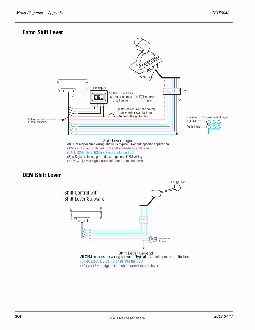
30
Wiring Diagrams | Appendix TRTS0062
Eaton Shift Lever
OEM Shift Lever
Gear display
J1C2
123 4
Ignition power (switched power)run to main power lead that
feeds the ignition bus
10 AMP 12 volt onlyautomatic resetting
circuit breaker10 AMP
fuseOr
Back side of gauges
Dash lights
Dimmer control input
E1
E2
E3
C1
D1
D2
D3
H2
B3
4 1 8 2 6 5 3
4 1 8 2 6 5 3
J2To Transmission 18-Way connector
All OEM responsible wiring shown is "typical". Consult specific application.(J2-4) = +12 volt switched from shift controler to shift lerver(D1-1, D2-8, D3-2, B3-5) = Signals into the ECU(3) = Signal returns, grounds, and general OEM wiring(H2-6) = +12 volt signal from shift control to shift lever
Shift Lever Legend
D1
D2
D3
H2
B A C
B A C
OEM Shift Lever
Service LampConnector
Shift Control withShift Lever Software
All OEM responsible wiring shown is "typical". Consult specific application.(D1-B, D2-A, D3-C) = Signals into the ECU(H2) = +12 volt signal from shift control to shift lever
Shift Lever Legend
4 © 2013 Eaton. All rights reserved 2013.07.17
TRTS0062 Appendix | Wiring Diagrams
2013.07.17 © 2013 Eaton. All rights reserved 305

30
Proper Clutch Operation | Appendix TRTS0062
Proper Clutch OperationWhen performing the test for Proper Clutch Operation, the vehicle should be in the same condition as when the prob-lem occurred. For instance, if the problem only occurs when the vehicle is hot, drive the vehicle to warm it up before conducting the test.
When the Operator presses the Clutch Pedal and shifts from neutral to drive or reverse, the Transmission Controller waits for the transmission Input Shaft speed to decrease to less than 150 RPM before shifting the transmission into gear. If the clutch is not disengaging completely or the clutch brake is not functioning properly, the Input Shaft will not slow down and the transmission will not shift into gear.
Check For Proper Clutch OperationWith PC-Based Service Tool
1. Connect PC-Based Service Tool.
2. Make sure the transmission is in neutral
3. Start engine.
4. Select “Input Shaft Speed.”
5. With Clutch Pedal up (clutch engaged), compare Input Shaft speed and engine speed (RPM). They should be the same.
Note: If engine speed and Input Shaft speeds are not the same, then perform Input Shaft Speed Sensor test and con-firm proper clutch adjustment.
6. Check clutch for slippage. Repair or replace as needed.
7. Press Clutch Pedal to Active clutch brake. Within 2 seconds, Input Shaft Speed should be less than 25 RPM (0 RPM is desired). If Input Shaft does not stop turning, the clutch is not disengaging com-pletely or the Clutch Brake is not functioning prop-erly.
8. Check for proper clutch adjustment, adjust as nec-essary.
9. Inspect Clutch Brake for excessive friction material wear or internal damage. Replace as necessary.
Note: The Clutch Brake may have to be removed to inspect properly.
10. If clutch adjustment is correct and Clutch Brake appears satisfactory, the problem may be a defec-tive clutch. The clutch may require repair or replacement. Refer to the clutch manufacturer’s service information to verify a dragging clutch.
Without PC-Based Service Tool
1. Place transmission in neutral.
2. Start engine.
3. Let up on the Clutch Pedal (clutch engaged).
4. Press Clutch Pedal fully to activate Clutch Brake and hold for 2 seconds.
5. Place transmission in starting gear.
6. If Gear Display shows a solid gear (engaged), the procedure is complete. If the gear display shows a flashing gear (not yet engaged) continue on to Step 7.
7. If flashing gear is displayed, slowly release the Clutch Pedal.
8. If flashing gear does not become solid or gear does not engage, check Clutch Brake for proper function and check clutch adjustment.
9. If gear does not engage and clutch is adjusted properly, troubleshoot for a dragging clutch according to clutch manufacturer.
Confirm Proper Clutch Adjustment and Clutch Brake Contact
Confirm Release Bearing Travel GapUse a 1/2” gauge to verify the Release Bearing travel gap. This gap (distance between the rear of the release bearing and the clutch brake) must be between 1/2” and 9/16”.
If this dimension is incorrect, adjust the clutch per the clutch manufacturer instructions.
Confirm the Free-Play Gap (For mechanical clutch release systems with free-play)Use a 1/8” or 1/16” gauge to verify proper free-play gap. This gap should be 1/8” Easy Pedal and 1/16” Solo.
If this dimension is incorrect, adjust the clutch per the clutch manufacturer instructions.
6 © 2013 Eaton. All rights reserved 2013.07.17

TRTS0062 Appendix | Proper Clutch Operation
Confirm Proper Clutch Brake ContactInsert a 0.010” Feeler gauge between the Release Bearing and the Clutch Brake. Have an assistant fully press the Clutch Pedal. The 0.010” Feeler gauge should be squeezed between the rear of the Release Bearing and the Clutch Brake. Have the assistant slowly let up the Clutch Pedal. The 0.010” Feeler gauge should slide out when the clutch pedal is 1/2” to 1” above the cab floor or lower Pedal Stop.
If the 0.010” Feeler gauge is not adequately squeezed to prevent removal, or can be removed with the pedal less than 1/2” or greater than 1”, check and adjust the Clutch Pedal height and travel per the chassis manufacturer instructions. In addition, check the external Clutch Linkage for excessive wear or obstruction preventing complete travel.
Releaseyoke
Clutchbrake
1/8"
1/2"
2013.07.17 © 2013 Eaton. All rights reserved 307

308 © 2013 Eaton. All rights reserved 2013.07.17
Adapter Test Kit J43318 | Appendix TRTS0062
Adapter Test Kit J43318
Gray AdaptersGray adapter are only used for the following connectors:
• Vehicle Harness 18-way
• Transmission Controller 30-way connector
• Shift Controller 30-way connector
• Speed Sensors
• Position Sensors
• Range Valve
• Splitter Valve
Purple AdaptersPurple adapter are only used for the following connectors:
• Motors
• Main Power
• Inertia Brake
Adapter PinsUse the male adapter to test the harness pins.Use the female adapter to test the component pins.
Harness
Male adapters
Component
Female adapters
2013.07.17 © 2013 Eaton. All rights reserved 309
TRTS0062 Appendix | Troubleshooting Worksheet
Troubleshooting Worksheet1. Have you been able to verify the concern.
2. Do you have any Active codes from the Service light on the console? If so, list them.
3. Detailed description of the complaint. How often does it occur? (Please try to avoid, “transmission won’t shift”).
a. When you notice the symptom/s, does the Service light flash or does the Operator notice an “F” in the Gear Display? In addition, does the Operator notice any “ABS” or “Check Engine” lights on?
b. When you notice the symptom/s, what does the Gear Display indicate? (flashing number, solid number, flashing arrows, blank display, etc.).
c. When the symptom/s occur, do you have con-trol of the throttle? If so, what RPM will the engine achieve?
d. When you stop the truck, will the transmis-sion return to neutral, or are you forced to shut the engine off with the transmission still in gear. If forced to shut down in gear, will the engine re-crank and what does the gear dis-play indicate?
e. Will the engine crank? If not, is the Service light flashing, and what does the Gear Display indicate?
f. Will the transmission engage a start gear from neutral? If not, is the Service light flash-ing, and what does the Gear Display indicate? If a Push Button Shift Controller, will the indi-cator lights follow the buttons?
4. What diagnosis or repairs have been made to this point?

Copyright Eaton, 2013. Eaton hereby grant their customers, vendors, or distributors permission to freely copy, reproduce and/or distribute this document in printed format. It may be copied only in its entirety without any changes or modifications. THIS INFOR-MATION IS NOT INTENDED FOR SALE OR RESALE, AND THIS NOTICE MUST REMAIN ON ALL COPIES.
Note: Features and specifications listed in this document are subject to change without notice and represent the maxi-mum capabilities of the software and products with all options installed. Although every attempt has been made to ensure the accuracy of information contained within, Eaton makes no repre-sentation about the completeness, cor-rectness or accuracy and assumes no responsibility for any errors or omis-sions. Features and functionality may vary depending on selected options.
For spec’ing or service assistance,
call 1-800-826-HELP (4357) or visit
www.eaton.com/roadranger.
In Mexico, call 001-800-826-4357.
Roadranger: Eaton and trusted partners providing the best products and ser-vices in the industry, ensuring more time on the road.
Eaton
Vehicle GroupP.O. Box 4013Kalamazoo, MI 49003 USA800-826-HELP (4357)www.eaton.com/roadranger
Printed in USA
Related Documents


