Welcome message from author
This document is posted to help you gain knowledge. Please leave a comment to let me know what you think about it! Share it to your friends and learn new things together.
Transcript

Brake Systems Application Guide
INDEX
INTRODUCTION
BRAKE SUMMARY AND KEY FEATURES 3
TYPICAL DESCRIPTION AND APPLICATIONS HYDRAULIC BRAKES 4-7
TYPICAL DESCRIPTION AND APPLICATIONS ELECTRIC BRAKES 8
BRAKE CALCULATIONSSELECTING BRAKE TORQUE BASED ON MOTOR DATA 9
CRANE HOIST BRAKING TORQUE 9
CRANE TROLLEY BRAKING TORQUE 10
SELECTING BRAKE SIZE BASED ON LOAD DATA 10
OVERHAULING LOAD TORQUE 12
BRAKE THERMAL CAPACITY 13
OVERHAULING LOADS 14
HYDRAULIC BRAKE SELECTION FOR BRIDGE BRAKES 15
HYDRAULIC BRAKE TORQUE RATINGS AND THERMAL CAPACITIES 16
DC MAGNETIC SHOE BRAKE TORQUE RATINGS AND THERMAL CAPACITIES 20
NOTE: Pages 9 through 14 describe brake calculations that in general apply to all styleGemco brakes. The hydraulic brake selection, pages 15 through 19 are specifically forhydraulic brakes used as bridge brakes for overhead cranes.
2

Brake Systems Application Guide
BRAKE SUMMARY AND KEY FEATURES
HYDRAULIC, MAGNETIC, ANDELECTRO-THRUST BRAKE SYSTEMS
Gemco Industrial Brakes stop virtually any type of industrial machine. Applications such as indoorand outdoor bridge cranes, gantries, heavy-duty cranes, high duty cycle cranes, lock and damprojects, stacker reclaimers, commercial laundry equipment, and heavy-duty industrial transferequipment are just some of the uses for Gemco Industrial Brakes.
These field-proven, high performance brake systems are tough and reliable, and they provideextended, trouble-free service. That’s because they are designed and built to exacting specifi-cations by Gemco. For more than 40 years, Gemco has been an acknowledged leader in brakesystems technology for heavy-duty industrial applications.
BRAKE SYSTEM KEY FEATURES SUMMARY
H HM AH AHM CB TM ET S DBHydraulically Applied • • • •Spring Applied • • • • •Controlled Stopping • • • •Parking • • • • • • •AISE Rated • • •
H - Manual Hydraulic Applied Brake SystemHM - Manual Hydraulic Brake with ParkingAH - Air-Over-Hydraulic Brake System, for remote controlAHM - Air-Over-Hydraulic Brake with ParkingCB - AC Brake, Spring SetTM - DC Brake, Spring Set (Auxiliary Hydraulic Cyl. available)ET - Electro-Thrust, Spring Set Release by Electro-Hydraulic Actuator
(Auxiliary Hydraulic Cylinder Available)DB - Electro-Thrust, Spring Set Release by Electro-Hydraulic Actuator
(Auxiliary Hydraulic Cylinder Available)
Note: Custom design and special brake assemblies are available; please consult factoryfor application assistance.
3

Brake Systems Application Guide
TYPICAL DESCRIPTION AND APPLICATIONSHYDRAULIC BRAKES
DESCRIPTION:
Type H manually operated hydraulic brakes forsmooth controlled service stops. Sizes are 6” through18” with torque ratings 150 to 900 ft-lbs.; one and twobrake systems.
TYPICAL APPLICATIONS:
Bridge brakes for overhead, gantries and heavy dutycranes. The hydraulic brakes described in thefollowing pages have been utilized for many years insteel mill cranes, shipyards and other applicationswhere an “operator” control stop is desirable.
DESCRIPTION:
Type HM brakes not only provide smooth controlledstopping but are also equipped with a spring appliedparking actuator. Sizes for single brake systems 6”through 18”, two brake systems 6” and 8”.
TYPICAL APPLICATIONS:
Bridge brakes for “outdoor” cranes that requireparking feature due to wind loads.
4

Brake Systems Application Guide
DESCRIPTION:
Type AH-ARC (Air/Hydraulic AirRemote Control) brake system forstopping large loads. Sizes one, twoand four brake systems - 6” through18”.
TYPICAL APPLICATIONS:
Large overhead crane brakes forladle cranes and other hot metalcranes, usually four brakes systems.
DESCRIPTION:
Type AH-H RC (Air/Hydraulic-Hydraulic Remote Control) brakesystems with operator hydrauliccontrol. Sizes one, two and fourbrake systems - 6” through 18”.
TYPICAL APPLICATIONS:
Bridge brakes for overhead cranewith moving trolley cabs that requiremore than 60 feet travel.
5

Brake Systems Application Guide
DESCRIPTION:
Type AH-ERC systems foroperating hydraulic brakes byradio or pendent control. Sizeone, two and four brake systems- 6” through 8” brake.
TYPICAL APPLICATIONS:
Any remote radio or pendentcontrol brake requirement forbridge brakes.
DESCRIPTION:
Type AH-ERC Conversionpackage adds remote controlcapability to existing H brakesystems. Size one and two brakesystems.
TYPICAL APPLICATIONS:
Field modification for remotecontrol capabilities on existingmanual system.
6
Brake Systems Application Guide
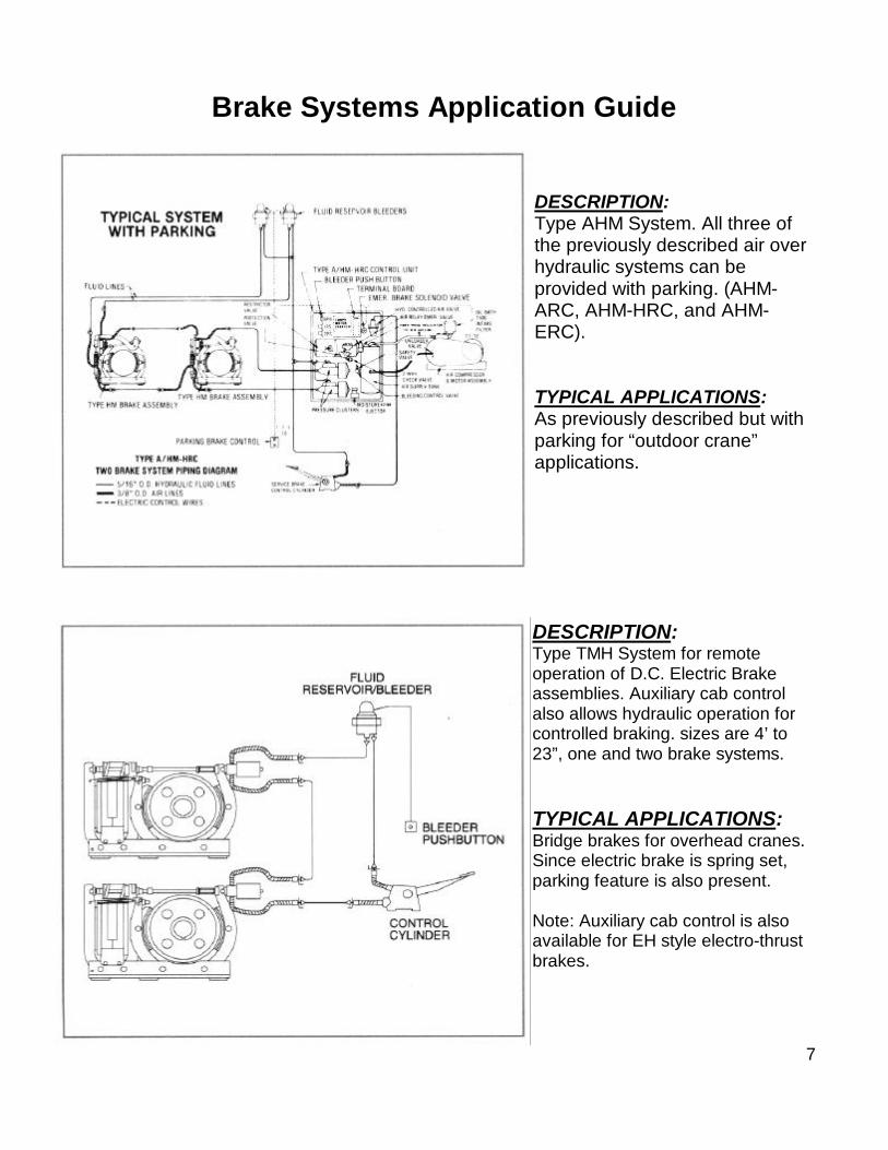
DESCRIPTION:Type AHM System. All three ofthe previously described air overhydraulic systems can beprovided with parking. (AHM-ARC, AHM-HRC, and AHM-ERC).
TYPICAL APPLICATIONS:As previously described but withparking for “outdoor crane”applications.
DESCRIPTION:Type TMH System for remoteoperation of D.C. Electric Brakeassemblies. Auxiliary cab controlalso allows hydraulic operation forcontrolled braking. sizes are 4’ to23”, one and two brake systems.
TYPICAL APPLICATIONS:Bridge brakes for overhead cranes.Since electric brake is spring set,parking feature is also present.
Note: Auxiliary cab control is alsoavailable for EH style electro-thrustbrakes.
7
Brake Systems Application Guide
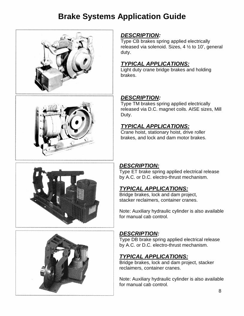
DESCRIPTION:Type CB brakes spring applied electricallyreleased via solenoid. Sizes, 4 ½ to 10’, generalduty.
TYPICAL APPLICATIONS:Light duty crane bridge brakes and holdingbrakes.
DESCRIPTION:Type TM brakes spring applied electricallyreleased via D.C. magnet coils. AISE sizes, MillDuty.
TYPICAL APPLICATIONS:Crane hoist, stationary hoist, drive rollerbrakes, and lock and dam motor brakes.
DESCRIPTION:Type ET brake spring applied electrical releaseby A.C. or D.C. electro-thrust mechanism.
TYPICAL APPLICATIONS:Bridge brakes, lock and dam project,stacker reclaimers, container cranes.
Note: Auxiliary hydraulic cylinder is also availablefor manual cab control.
DESCRIPTION:Type DB brake spring applied electrical releaseby A.C. or D.C. electro-thrust mechanism.
TYPICAL APPLICATIONS:Bridge brakes, lock and dam project, stackerreclaimers, container cranes.
Note: Auxiliary hydraulic cylinder is also availablefor manual cab control.
8
Brake Systems Application Guide
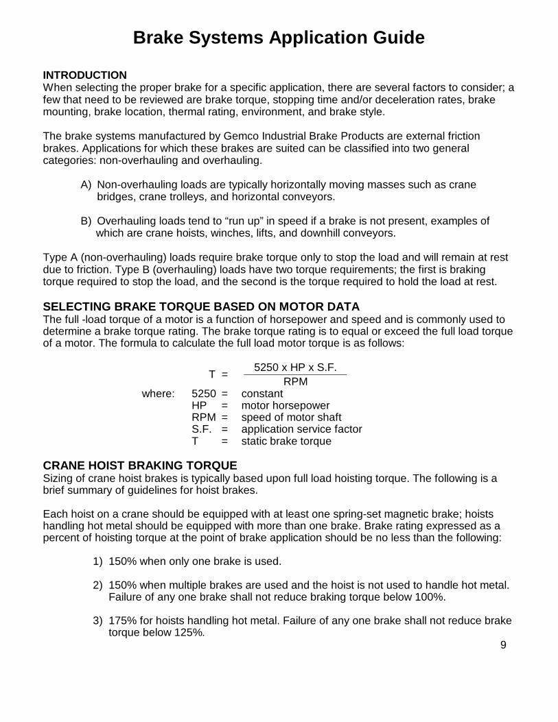
INTRODUCTIONWhen selecting the proper brake for a specific application, there are several factors to consider; afew that need to be reviewed are brake torque, stopping time and/or deceleration rates, brakemounting, brake location, thermal rating, environment, and brake style.
The brake systems manufactured by Gemco Industrial Brake Products are external frictionbrakes. Applications for which these brakes are suited can be classified into two generalcategories: non-overhauling and overhauling.
A) Non-overhauling loads are typically horizontally moving masses such as cranebridges, crane trolleys, and horizontal conveyors.
B) Overhauling loads tend to “run up” in speed if a brake is not present, examples of which are crane hoists, winches, lifts, and downhill conveyors.
Type A (non-overhauling) loads require brake torque only to stop the load and will remain at restdue to friction. Type B (overhauling) loads have two torque requirements; the first is brakingtorque required to stop the load, and the second is the torque required to hold the load at rest.
SELECTING BRAKE TORQUE BASED ON MOTOR DATAThe full -load torque of a motor is a function of horsepower and speed and is commonly used todetermine a brake torque rating. The brake torque rating is to equal or exceed the full load torqueof a motor. The formula to calculate the full load motor torque is as follows:
5250 x HP x S.F. T =
RPMwhere: 5250 = constant
HP = motor horsepowerRPM = speed of motor shaftS.F. = application service factorT = static brake torque
CRANE HOIST BRAKING TORQUESizing of crane hoist brakes is typically based upon full load hoisting torque. The following is abrief summary of guidelines for hoist brakes.
Each hoist on a crane should be equipped with at least one spring-set magnetic brake; hoistshandling hot metal should be equipped with more than one brake. Brake rating expressed as apercent of hoisting torque at the point of brake application should be no less than the following:
1) 150% when only one brake is used.
2) 150% when multiple brakes are used and the hoist is not used to handle hot metal.Failure of any one brake shall not reduce braking torque below 100%.
3) 175% for hoists handling hot metal. Failure of any one brake shall not reduce braketorque below 125%.
9

Brake Systems Application Guide
CRANE TROLLEY BRAKING TORQUECrane trolley brakes are typically sized with a torque rating less than the motor’s full load torque(service factor less than 1.0) to provide a longer stopping time or a “soft stop.” Overhead cranetrolley brakes are minimized to prevent sway of the hook and load. Typical service factor is 50%for “soft stopping.”
SELECTING BRAKE SIZE BASED ON LOAD DATAFor applications where high inertial loads exist or where a specific stopping time or distance isrequired, the brake should be selected based on the total inertia of the load. Total system inertiareflected to the brake shaft can be expressed as follows:
WKT2 = WKB
2 + WKM2 + WKL
2
where: WKT2 = Total reflected inertia to brake (Ib-ft2)
WKB2 = Inertia of brake wheel (Ib-ft2)
WKM2 = Inertia of motor rotor (Ib-ft2)
WKL2 = Equivalent inertia of load reflected to
shaft (lb-ft2) brake
The following formulas apply when calculating inertia of systems with different rotational speedsor linear moving loads to brake shaft speeds.
Rotary Motion:
WKb2 = WKL
2 (NL / NB)2
where: WKb2 = Inertia of rotation load reflected to brake shaft
(lb-ft2)
WKL2 = Inertia of rotating load (lb-ft2)
NL = Shaft speed at load (RPM)
NB = Shaft speed at brake (RPM)
10

Brake Systems Application Guide
Horizontal Linear Motion:
WKW2
= W (V / 2pNB)2
where: WKW2 = Equivalent inertia of moving load
reflected to brake shaft (lb-ft2)
W = Weight of linear load (Ib)
V = Linear velocity of load (ft/mm)
NB = Shaft speed at brake (RPM)
With the total system inertia calculated, the required average dynamic torque for a desiredstopping time can be calculated using the following formula:
WKT2
x NBTd =308 x t
where: Td = Average dynamic braking torque (lb-ft)
WKT2 = Total inertia reflected to brake (lb-ft2)
NB = Shaft speed at brake (RPM)
t = Desired stopping time (sec.)
308 = Constant
To determine stopping time for a given brake torque this formula can be rewritten as follows:
WKT2 * NBt = 308 x Td
For some brake styles the time required until the brake lining makes contact with the wheel maybe significant. Time required to stop is then as follows:
WKT2xNBt = t1 +
308 x Tdwhere: t1 = Time between signal and moment when brake
torque is actually applied (sec.)
11
Brake Systems Application Guide
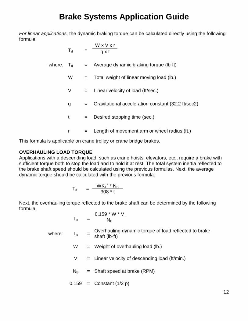
For linear applications, the dynamic braking torque can be calculated directly using the followingformula:
W x V x rTd = g x t
where: Td = Average dynamic braking torque (lb-ft)
W = Total weight of linear moving load (lb.)
V = Linear velocity of load (ft/sec.)
g = Gravitational acceleration constant (32.2 ft/sec2)
t = Desired stopping time (sec.)
r = Length of movement arm or wheel radius (ft.)
This formula is applicable on crane trolley or crane bridge brakes.
OVERHAULING LOAD TORQUEApplications with a descending load, such as crane hoists, elevators, etc., require a brake withsufficient torque both to stop the load and to hold it at rest. The total system inertia reflected tothe brake shaft speed should be calculated using the previous formulas. Next, the averagedynamic torque should be calculated with the previous formula:
WKT2 * NBTd = 308 * t
Next, the overhauling torque reflected to the brake shaft can be determined by the followingformula:
0.159 * W * VTo = NB
where: To = Overhauling dynamic torque of load reflected to brakeshaft (lb-ft)
W = Weight of overhauling load (lb.)
V = Linear velocity of descending load (ft/min.)
NB = Shaft speed at brake (RPM)
0.159 = Constant (1/2 p)
12

Brake Systems Application Guide
The total dynamic torque required for an overhauling load is the sum of Td and T0, as follows:
Tt = Td + To
where: Tt = Total dynamic torque for descending load
BRAKE THERMAL CAPACITYWhen a brake stops a load, the energy required to stop is converted to heat. This heat isabsorbed by the brake and the wheel. The ability to absorb and dissipate heat without exceedingtemperature limitations is known as thermal capacity.
There are two types of thermal capacity. The first is referred to as the maximum energy the brakecan absorb in one stop, or emergency stop. The second is the heat dissipation capability of thebrake if it is for frequent stopping.
The kinetic energy that must be absorbed and dissipated by the brake can be determined asfollows:
Rotational Loads:
WKT2 X NB
2
KEr = 5875
where: KEr = Kinetic energy of rotating load (ft-lb)
WKT2 = Inertia of the rotating load reflected to brake shaft (Ib-ft2)
NB = Shaft speed at brake (RPM)
5875 = Constant
W x V2
KEL = 2g
where: KEL = Kinetic energy (ft-lb)
W = Weight of load (lb.)
V = Linear velocity of load, (ft/sec.)
g = Gravitational constant (32.2 ft/sec2)
13
Brake Systems Application Guide
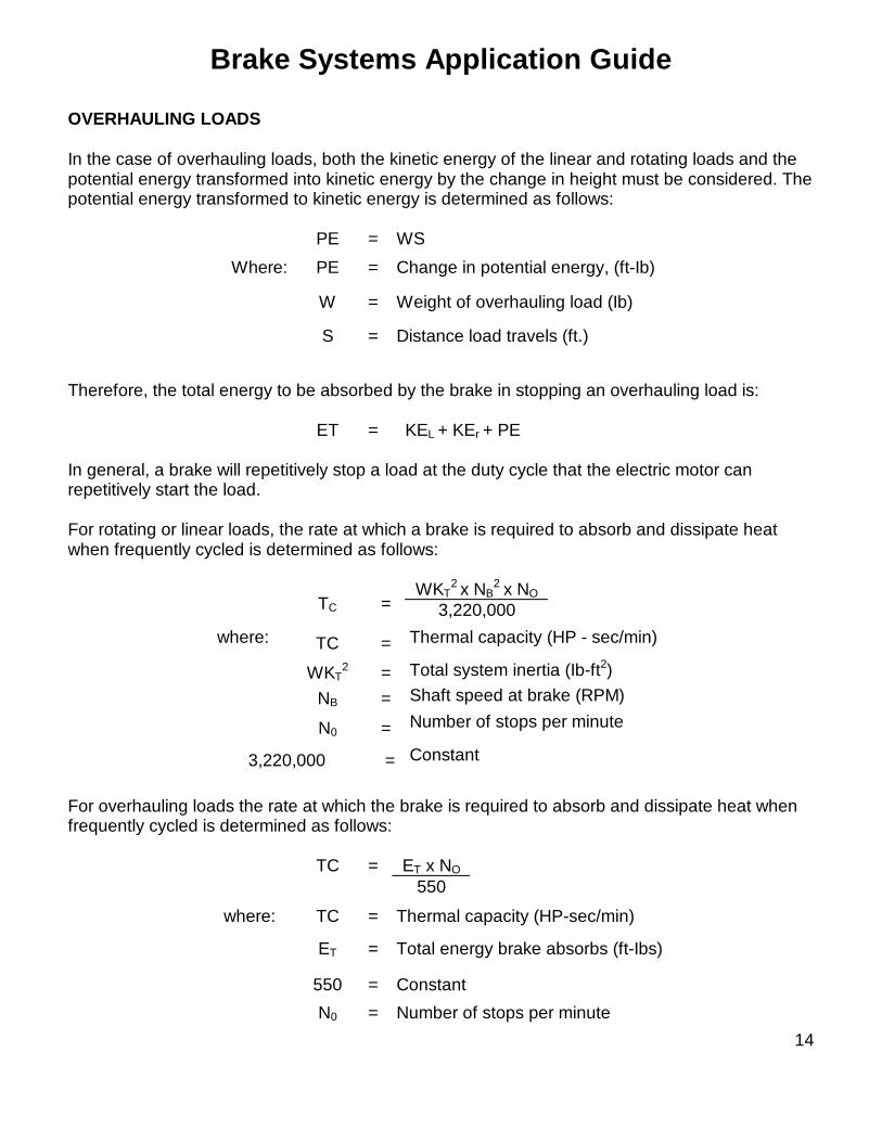
OVERHAULING LOADS
In the case of overhauling loads, both the kinetic energy of the linear and rotating loads and thepotential energy transformed into kinetic energy by the change in height must be considered. Thepotential energy transformed to kinetic energy is determined as follows:
PE = WS
Where: PE = Change in potential energy, (ft-Ib)
W = Weight of overhauling load (Ib)
S = Distance load travels (ft.)
Therefore, the total energy to be absorbed by the brake in stopping an overhauling load is:
ET = KEL + KEr + PE
In general, a brake will repetitively stop a load at the duty cycle that the electric motor canrepetitively start the load.
For rotating or linear loads, the rate at which a brake is required to absorb and dissipate heatwhen frequently cycled is determined as follows:
WKT2 x NB
2 x NOTC = 3,220,000
TC = Thermal capacity (HP - sec/min)
WKT2 = Total system inertia (Ib-ft2)
NB = Shaft speed at brake (RPM)
where:
N0 = Number of stops per minute
3,220,000 = Constant
For overhauling loads the rate at which the brake is required to absorb and dissipate heat whenfrequently cycled is determined as follows:
TC = ET x NO
550
where: TC = Thermal capacity (HP-sec/min)
ET = Total energy brake absorbs (ft-Ibs)
550 = Constant
N0 = Number of stops per minute14

Brake Systems Application Guide
BRAKE SELECTION FOR BRIDGE BRAKES
The following formulas apply for calculating linear loads such as bridge brake applications:
W x V2 W x V x rKEL = 2 x g Td = g x twhere: KEL = Kinetic energy (ft-lb)
W = Weight (lb.)
V = Linear velocity (ft/sec)
G = Gravitational constant (32.2 ft/sec2)
R = Wheel radius (ft)
T = Stopping time
Td = Average dynamic torque (lb-ft)
Given in terms of tons, wheel diameter, gear ratios, etc., the specifications necessary tocalculate crane bridge brakes include the following:
Empty crane weight — WE _____TonsFull load crane weight — WL _____TonsMax. bridge speed — FPM _____Ft/Min.Stops per hour — N _____Number valueTrack wheel diameter — DIA _____Inches*Gear ratio brake shaft to track wheel — R _____(To 1)Number of brakes — NB _____Number valueAcceleration rate — A _____Ft/Sec2.Min. deceleration rate — dMN _____Ft/Sec2.Max. deceleration rate — dMX _____Ft/Sec2.Drive motor inertia — WKM
2 _____(Lb-Ft2)
* Drive motor RPM can be used to verify gear ratios, etc., for a maximum speed and trackdiameter.
In general, service bridge brakes should have sufficient thermal and torque range to stopthe bridge within a distance of 10% of the full load speed with full load, or at a decelerationrate as specified by the original manufacturer.
15

Brake Systems Application Guide
The kinetic energy and torque calculations can be stated in terms of crane specifications asfollows:
Kinetic energy absorption rate, per brake per hour:
N x (FPM)2 x (WE + WL)KE = 232 x NB
Minimum stopping torque (to stop empty crane at minimum deceleration rate):
2.59 x WE x dMN x DIATMN = NB x R
Maximum stopping torque (to stop fully loaded crane at maximum deceleration rate):
2.59 x WL x dMX x DIATMX = NB x R
HYDRAULIC BRAKE TORQUE RATINGS AND THERMAL CAPACITIES
Using the table below, select the smallest brake size that will exceed KE and TMX calculationslisted above. TMN calculations for air powered systems should be above “Minimum” torquelimits below:
Max. Dynamic Torque per Brake (Ib-ft.)**BrakeSize
Max. KE perBrake per Hour
(ft.-Ib) Type H 1-Brake Type H 2-Brake or Type HM All Air
Powered
Min. Dynamic Torque, All AirPowered Systems (lb-ft.)
6 x 3 1.0 x 10⁶ 150 150 350 25
8 x 3 1.25 x 10⁶ 200 200 450 50
10 x 4 2.5 x 10 425 250 1000 75
14 x 6 5.0 x 10⁶ 600 350 1400 125
18 x 8 9.0 x 10⁶ 900 550 1800 175
**Based on 70 lb. pedal force, 8” max. pedal travel on Type H or HM manual systems.
16

Brake Systems Application Guide
Maximum stops per hour can be calculated using the following:
N x (Max. KE per brake per hour)Max. stops/hr. = KE
where: (Max. KE per brake per hour) = Value for brake size as shown in table above.
The additional torque required to stop the drive rotor and the brake wheel inertia is normallyinsignificant and is ignored when the gear ratio (R) is less than about 10 x 1. If the gear ratio, andthus the drive rotor inertia is abnormally high, considerable torque may be needed just to stop thedrive rotor.
To calculate the additional torque needed to stop the drive rotor and brake wheel inertia, proceedas follows:
1. Complete the previous calculations to establish the prelimary brake size.
BRAKE SIZE BRAKE WHEEL INERTIA6 x 3 .55 lb-Ft2.8 x 3 1.41 Lb-Ft2.
10 x 4 4.25 Lb-Ft2.14 x 6 24.20 Lb-Ft2.18 x 8 75.73 Lb-Ft2.
2. Record the following data from brake wheel inertia table above and additional data fromprevious calculations.
WK2 Brake wheel Inertia _________________ Lb-Ft2.
WK2 Drive Rotor Inertia + Lb-Ft2.
WK2 Total (Drive Motor and Wheel) _________________ Lb-Ft2.
R, Gear Ratio _________________ x1
dMN Deceleration Rate _________________ ft/sec2.
dMX Deceleration Rate @ Full Load _________________ ft/sec2.
DIA, Track Wheel _________________ inches
3. Calculate No Load Drive Torque, TNLD:
WK2Total x R x dMN = ________ x ________ x ________ 1.34 x DIA. _____________________________ = ________Lb-Ft.
1.34 x _______
4. Calculate Full Load Drive Torque, TFLD:
TNLD X dMX = ________ x ________ = ________ Lb-Ft. dMN ________
17

Brake Systems Application Guide
5.Calculate Total Minimum and Maximum Torques:
TMN (previous) ___________Lb-Ft. TMX (previous) ___________Lb-Ft.
TNLD + ___________ Lb-Ft. TFLD + Lb-Ft.
TMNT ___________ Lb-Ft. TMxT Lb-Ft.
6.Check to determine that TMxT is still within the torque limits of the brake size selected. Ifnecessary, recalculate the problem based on alternate brake size and brakewheel inertia.
The chart below shows the dynamic torque values developed by manually operated brakesystems. Maximum torques tabulated are developed at 70 lb. pedal force, the limit indicated byAISE and OSHA. Two maximum values are shown for 10 x 4, 14 x 6, and 18 x 8 brakes, asfollows:
The chart below shows the dynamic torque ranges developed by air powered hydraulicsystems.
The maximum torques shown are developed by a 70 lb. force applied on the air treadle onType A/H systems or applied on the pedal of the control cylinder on Type NHM-HRC systems.Air powered hydraulic systems include either a 1 x 5 or a 1 x 8 air hydraulic pressure cluster toapply the service brake. In addition, 10”, 14”, and 18” brakes include either a 7/8” diameter or a1-1/8” diameter service brake actuator. Hence, 6” and 8” brakes have two possible maximumtorque limits, while 10”, 14”, and 18” have four possible maximum torque limits.
The minimum torque limits shown are developed by light application of the treadle or pedal.Because of hysteresis and friction in the power system valves, it is not practical to consistentlycontrol less torque than the minimum calculated.
18

Brake Systems Application Guide
Static holding torque values tabulated below are those developed by the parking spring on theType HM brakes. The brake must be correctly adjusted in order to get the holding torquetabulated.
Brake Size 6 x 3 8 x 3 10 x 4 14 x 6 18 x 8Holding Torque, lb-ft. 35 50 450 550 700
19

Brake Systems Application GuideTM, ET and DB SHOE BRAKE TORQUE RATINGS AND THERMAL CAPACITIES
Maximum Torque in Lbs.-Ft (Max.)Series Brake Shunt Brake
1/2 HR 1 HR 1 HR 8 HRTM 43TM 63TM 83TM 1035TM 1355TM 1655TM 1985TM 2311TM 3014
25501002005501000200040009000
154065130365650130026006000
25501002005501000200040009000
154075150400750150030006750
BRAKESTYLE
WHEELDIAMETER
(inches)
TORQUELB.FT.(Max.)
ET8 8 100
ET10 10 200
ET13 13 550
ET16 16 1000
ET19 19 2000
ET23 23 4000
ET30 30 9000
WheelSize
Ft.-Lb.per Hour
4.5” 396,000
6.0” 660,000
8.0” 990,000
10” 1,716,000
13” 3,300,000
16” 5,016,000
19” 7,425,000
23” 10,890,000
30” 18,150,000
BRAKESTYLE
DISCDIAMETER
(Inches)
TORQUELB.FT.(Max.)
DB12 12 100
DB14 14 200
DB17 17 550
Allowable Heat Absorption for Brake Wheels DB Torque Ratings
TM Torque Ratings ET Torque Ratings
AMETEK®
PATRIOT SENSORS6380 BROCKWAY ROAD • PECK, MI 48466-9766 USA
800-325-8074 • 810-378-5511 • Fax 810-378-5516www.patriotsensors.com • www.ametek.com
Related Documents