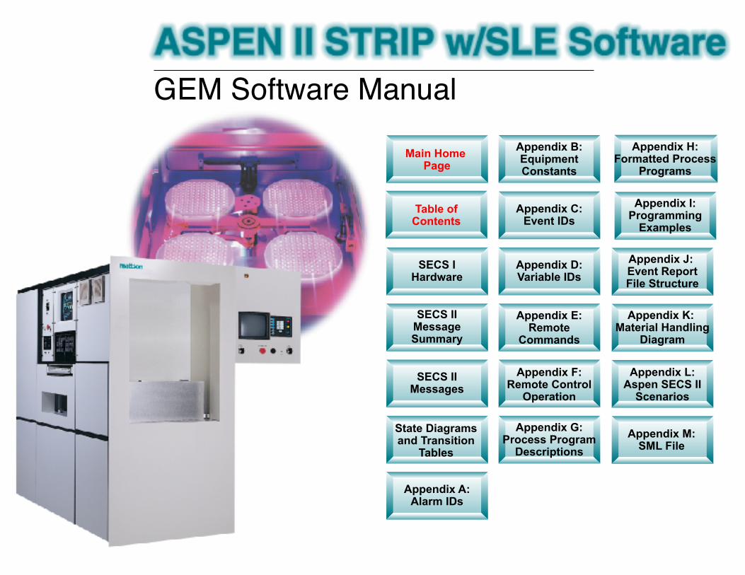
GEM Software Manual Main Home Page Appendix H: Formatted Process Programs SECS I Hardware SECS II Message Summary SECS II Messages State Diagrams and Transition Tables Appendix A: Alarm IDs Table of Contents Appendix C: Event IDs Appendix D: Variable IDs Appendix E: Remote Commands Appendix F: Remote Control Operation Appendix G: Process Program Descriptions Appendix B: Equipment Constants Appendix J: Event Report File Structure Appendix K: Material Handling Diagram Appendix L: Aspen SECS II Scenarios Appendix M: SML File Appendix I: Programming Examples

Welcome message from author
This document is posted to help you gain knowledge. Please leave a comment to let me know what you think about it! Share it to your friends and learn new things together.
Transcript
GEM Software Manual
Main Home Page
Appendix H: Formatted Process
Programs
SECS I Hardware
SECS II Message Summary
SECS II Messages
State Diagrams and Transition
Tables
Appendix A: Alarm IDs
Table ofContents
Appendix C: Event IDs
Appendix D: Variable IDs
Appendix E: Remote
Commands
Appendix F: Remote Control
Operation
Appendix G: Process Program
Descriptions
Appendix B: Equipment Constants
Appendix J: Event Report File Structure
Appendix K: Material Handling
Diagram
Appendix L: Aspen SECS II
Scenarios
Appendix M: SML File
Appendix I: Programming
Examples

175-19567-00 - Rev. A21Sep02
Mattson Technology, Inc.2800 Bayview DriveFremont, CA 94538
Integrated Syst
MaintenancProcedu
Operation an
Aspen II SLE SECS II/GEMManual
Aspen II SLE SECS II/GEM Manual
175-19567-00 – Rev. A 21Sep02

Aspen II SLE SECS II/GEM Manual User Information
175-19567-00 – Rev. A 21Sep02
Service InformationMattson’s Technical Support and Customer Support Departments are open 24 hours per day, 7 days per week. Please have your model number, serial number, and phone number ready when you call any of the numbers listed on this page.
Global Customer and Technical SupportContact Customer Support for billing and shipping questions, field support for warranty and installation questions. Customer support will direct your service call to the appropriate department, such as Technical Support or Spare Parts.
Phone: 1 (800) 315-6607 (USA, toll-free, 24/7) or(845) 575-6203 (International, 24/7)FAX: (510) 226-8241
Plasma Products Global Technical Supportemail: [email protected]
Spare PartsContact Spare Parts for spare parts orders.
Phone: 1 (800) 315-6607 (USA, toll-free, 24/7) or(845) 575-6203 (International, 24/7)FAX: (510) 492-6369 (USA/Asia)(610) 280-8407 (Europe)email: [email protected]
Mattson Corporate Headquarters2800 Bayview DriveFremont, CA 94538Tel: (510) 657-5900email: [email protected] the web at: www.mattson.com
About this ManualContact Mattson Technical Publications for additions or corrections to this Manual [email protected]

User Information Aspen II SLE SECS II/GEM Manual
175-19567-00 – Rev. A 21Sep02
DisclaimerMattson Technology, Inc. makes no representations or warranties with respect to this manual, except as outlined in the product warranty. Further, Mattson reserves the right to make changes in the specifications of the product described in the manual at any time, without notice, and without obligation to Mattson Technology.
Copyright ©2002 by Mattson Technology Inc.
Copyright under International, Pan American, and Universal Copyright Conventions. All rights reserved. This manual may not be reproduced, either wholly or in part, for any reason whatsoever, without the prior written permission of Mattson Technology, Inc.

TABLE OF CONTENTS
1.0 SECS I Hardware . . . . . . . . . . . . . . . . . . . . . . . . . . . . . . . . . . . . . . . . 1-11.1 Applicable Equipment . . . . . . . . . . . . . . . . . . . . . . . . . . . . . . . . . . . . . . . . . . . . . . . . . . . . . . . . . . . . . . 1-11.2 SECS I Hardware . . . . . . . . . . . . . . . . . . . . . . . . . . . . . . . . . . . . . . . . . . . . . . . . . . . . . . . . . . . . . . . . . .1-11.3 Loading The SIB . . . . . . . . . . . . . . . . . . . . . . . . . . . . . . . . . . . . . . . . . . . . . . . . . . . . . . . . . . . . . . . . 1-11.4 SIB Configuratio n . . . . . . . . . . . . . . . . . . . . . . . . . . . . . . . . . . . . . . . . . . . . . . . . . . . . . . . . . . . . . . . . . . 1-11.5 Equipment Monitoring of Host and Message Spooling . . . . . . . . . . . . . . . . . . . . . . . . . . . . . . . . . . . . 1-31.6 Software Revision . . . . . . . . . . . . . . . . . . . . . . . . . . . . . . . . . . . . . . . . . . . . . . . . . . . . . . . . . . . . . . . . . 1-3
2.0 Support SECS II Message Summary . . . . . . . . . . . . . . . . . . . . . . . . . 2-1
3.0 Supported SECS II Messages . . . . . . . . . . . . . . . . . . . . . . . . . . . . . . . 3-13.1 SxF0 . . . . . . . . . . . . . . . . . . . . . . . . . . . . . . . . . . . . . . . . . . . . . . . . . . . . . . . . . . . . . . . . . . . . . . . . . 3-1
SxF0 Abort Transaction . . . . . . . . . . . . . . . . . . . . . . . . . . . . . . . . . . . . . . . . . . . . . . . . . . . . . . 3-1
3.2 S1Fx . . . . . . . . . . . . . . . . . . . . . . . . . . . . . . . . . . . . . . . . . . . . . . . . . . . . . . . . . . . . . . . . . . . . . . . . . 3-1S1F1 Are You There Request (R) . . . . . . . . . . . . . . . . . . . . . . . . . . . . . . . . . . . . . . . . . . . . . . . 3-1S1F2 On Line Data (D) . . . . . . . . . . . . . . . . . . . . . . . . . . . . . . . . . . . . . . . . . . . . . . . . . . . . . . . 3-1S1F3 Selected Equipment Status Request (SSR) . . . . . . . . . . . . . . . . . . . . . . . . . . . . . . . . . . . 3-1S1F4 Selected Equipment Status Data (SSD) . . . . . . . . . . . . . . . . . . . . . . . . . . . . . . . . . . . . . . 3-2S1F9 Material Transfer Status Request (TSR) . . . . . . . . . . . . . . . . . . . . . . . . . . . . . . . . . . . . . 3-2S1F10 Material Transfer Status Data (TSD) . . . . . . . . . . . . . . . . . . . . . . . . . . . . . . . . . . . . . . . . 3-2S1F11 Status Variable Namelist (SVNR) . . . . . . . . . . . . . . . . . . . . . . . . . . . . . . . . . . . . . . . . . . 3-2S1F12 Status Variable Namelist Reply (SVNRR) . . . . . . . . . . . . . . . . . . . . . . . . . . . . . . . . . . . 3-3S1F13 Establish Communication Request (ECR) . . . . . . . . . . . . . . . . . . . . . . . . . . . . . . . . . . . . 3-3S1F14 Establish Communications Request Acknowledge (CRA) . . . . . . . . . . . . . . . . . . . . . . . . 3-3S1F15 Request OFF-LINE (ROFL) . . . . . . . . . . . . . . . . . . . . . . . . . . . . . . . . . . . . . . . . . . . . . . . 3-4S1F16 OFF-LINE Acknowledge . . . . . . . . . . . . . . . . . . . . . . . . . . . . . . . . . . . . . . . . . . . . . . . . . 3-4S1F17 Request ON-LINE (RONL) . . . . . . . . . . . . . . . . . . . . . . . . . . . . . . . . . . . . . . . . . . . . . . . 3-4S1F18 ON-LINE Acknowledge (ONLA) . . . . . . . . . . . . . . . . . . . . . . . . . . . . . . . . . . . . . . . . . . 3-4
3.3 S2Fx . . . . . . . . . . . . . . . . . . . . . . . . . . . . . . . . . . . . . . . . . . . . . . . . . . . . . . . . . . . . . . . . . . . . . . . . . . .3-4S2F13 Equipment Constant Request (ECR) . . . . . . . . . . . . . . . . . . . . . . . . . . . . . . . . . . . . . . . . . 3-4S2F14 Equipment Constant Data (ECD) . . . . . . . . . . . . . . . . . . . . . . . . . . . . . . . . . . . . . . . . . . . 3-5S2F15 New Equipment Constant Send (ECS) . . . . . . . . . . . . . . . . . . . . . . . . . . . . . . . . . . . . . . 3-5S2F16 New Equipment Constant Acknowledge (ECA) . . . . . . . . . . . . . . . . . . . . . . . . . . . . . . . 3-5S2F17 Date and Time Request (DTR) . . . . . . . . . . . . . . . . . . . . . . . . . . . . . . . . . . . . . . . . . . . . . 3-5S2F18 Date and Time Data (DTD) . . . . . . . . . . . . . . . . . . . . . . . . . . . . . . . . . . . . . . . . . . . . . . . 3-6S2F21 Remote Command Send (RCS) . . . . . . . . . . . . . . . . . . . . . . . . . . . . . . . . . . . . . . . . . . . . 3-6S2F22 Remote Command Acknowledge (RCA) . . . . . . . . . . . . . . . . . . . . . . . . . . . . . . . . . . . . . 3-6S2F23 Trace Initialize Send (TIS) . . . . . . . . . . . . . . . . . . . . . . . . . . . . . . . . . . . . . . . . . . . . . . . . 3-6S2F24 Trace Initialize Acknowledge (TIA) . . . . . . . . . . . . . . . . . . . . . . . . . . . . . . . . . . . . . . . . . 3-7S2F25 Loopback Diagnostic Request (LDR) . . . . . . . . . . . . . . . . . . . . . . . . . . . . . . . . . . . . . . . . 3-7S2F26 Loopback Diagnostic Data (LDD) . . . . . . . . . . . . . . . . . . . . . . . . . . . . . . . . . . . . . . . . . . 3-7S2F27 Initiate Processing Request (IPR) . . . . . . . . . . . . . . . . . . . . . . . . . . . . . . . . . . . . . . . . . . . 3-7S2F28 Initiate Processing Acknowledge (IPA) . . . . . . . . . . . . . . . . . . . . . . . . . . . . . . . . . . . . . . 3-8S2F29 Equipment Constant Namelist Request (ECNR) . . . . . . . . . . . . . . . . . . . . . . . . . . . . . . . 3-8
175-19567-00, Rev. A Aspen Strip SECS II/GEM Manual iii
Table of Contents
S2F30 Equipment Constant Namelist (ECN) . . . . . . . . . . . . . . . . . . . . . . . . . . . . . . . . . . . . . . . . 3-8S2F31 Date and Time Set Request (DTS) . . . . . . . . . . . . . . . . . . . . . . . . . . . . . . . . . . . . . . . . . . 3-8S2F32 Date and Time Set Acknowledge (DTA) . . . . . . . . . . . . . . . . . . . . . . . . . . . . . . . . . . . . . 3-9S2F33 Define Report (DR) . . . . . . . . . . . . . . . . . . . . . . . . . . . . . . . . . . . . . . . . . . . . . . . . . . . . . . 3-9S2F34 Define Report Acknowledge (DRA) . . . . . . . . . . . . . . . . . . . . . . . . . . . . . . . . . . . . . . . . 3-10S2F35 Link Event Report (LER) . . . . . . . . . . . . . . . . . . . . . . . . . . . . . . . . . . . . . . . . . . . . . . . . 3-10S2F36 Link Event Report Acknowledge (LERA) . . . . . . . . . . . . . . . . . . . . . . . . . . . . . . . . . . . 3-11S2F37 Enable/Disable Event Report (EDER) . . . . . . . . . . . . . . . . . . . . . . . . . . . . . . . . . . . . . . 3-11S2F38 Enable/Disable Event Report Acknowledge (EERA) . . . . . . . . . . . . . . . . . . . . . . . . . . . 3-11S2F39 Multi-Block Inquire (DMI) . . . . . . . . . . . . . . . . . . . . . . . . . . . . . . . . . . . . . . . . . . . . . . 3-11S2F40 Multi-Block Grant (DMBG) . . . . . . . . . . . . . . . . . . . . . . . . . . . . . . . . . . . . . . . . . . . . . . 3-12S2F41 Host Command Send (HCS) . . . . . . . . . . . . . . . . . . . . . . . . . . . . . . . . . . . . . . . . . . . . . . 3-12S2F42 Host Command Acknowledge (HCA) . . . . . . . . . . . . . . . . . . . . . . . . . . . . . . . . . . . . . . 3-12S2F43 Reset Spooling Streams and Functions . . . . . . . . . . . . . . . . . . . . . . . . . . . . . . . . . . . . . . 3-13S2F44 Reset Spooling Acknowledge (RSA) . . . . . . . . . . . . . . . . . . . . . . . . . . . . . . . . . . . . . . . 3-14S2F45 Variable Limit Attribute Request (VLAR) . . . . . . . . . . . . . . . . . . . . . . . . . . . . . . . . . . . 3-14S2F46 Variable Limit Attribute Acknowledge (VLAA) . . . . . . . . . . . . . . . . . . . . . . . . . . . . . . 3-15S2F47 Variable Limit Attribute Request (VLAR) . . . . . . . . . . . . . . . . . . . . . . . . . . . . . . . . . . . 3-16S2F48 Variable Limit Attributes Send (VLAS) . . . . . . . . . . . . . . . . . . . . . . . . . . . . . . . . . . . . . 3-16
3.4 S3Fx . . . . . . . . . . . . . . . . . . . . . . . . . . . . . . . . . . . . . . . . . . . . . . . . . . . . . . . . . . . . . . . . . . . . . . . . . . 3-17S3F11 Material ID Request (MIDR) . . . . . . . . . . . . . . . . . . . . . . . . . . . . . . . . . . . . . . . . . . . . . 3-17S3F12 Material ID Request Acknowledge (MIRA) . . . . . . . . . . . . . . . . . . . . . . . . . . . . . . . . . . 3-17S3F13 Material ID Send . . . . . . . . . . . . . . . . . . . . . . . . . . . . . . . . . . . . . . . . . . . . . . . . . . . . . . . 3-17S3F14 Material ID Acknowledge . . . . . . . . . . . . . . . . . . . . . . . . . . . . . . . . . . . . . . . . . . . . . . . . 3-18
3.5 S4Fx . . . . . . . . . . . . . . . . . . . . . . . . . . . . . . . . . . . . . . . . . . . . . . . . . . . . . . . . . . . . . . . . . . . . . . . . . . 3-18S4F1 Ready to Send Material (RSN) . . . . . . . . . . . . . . . . . . . . . . . . . . . . . . . . . . . . . . . . . . . . 3-18S4F2 Ready to Send Acknowledge (RSA) . . . . . . . . . . . . . . . . . . . . . . . . . . . . . . . . . . . . . . . . 3-18S4F3 Send Material (SMN) . . . . . . . . . . . . . . . . . . . . . . . . . . . . . . . . . . . . . . . . . . . . . . . . . . . 3-18S4F5 Handshake Complete (HCN) . . . . . . . . . . . . . . . . . . . . . . . . . . . . . . . . . . . . . . . . . . . . . 3-19S4F7 Not Ready to Send (ABN) . . . . . . . . . . . . . . . . . . . . . . . . . . . . . . . . . . . . . . . . . . . . . . . 3-19S4F9 Stuck in Sender (SSN) . . . . . . . . . . . . . . . . . . . . . . . . . . . . . . . . . . . . . . . . . . . . . . . . . . 3-19S4F11 Stuck in Receiver (SRN) . . . . . . . . . . . . . . . . . . . . . . . . . . . . . . . . . . . . . . . . . . . . . . . . . 3-19S4F13 Send Incomplete Time-Out (SIN) . . . . . . . . . . . . . . . . . . . . . . . . . . . . . . . . . . . . . . . . . . 3-20S4F15 Material Received (MRN) . . . . . . . . . . . . . . . . . . . . . . . . . . . . . . . . . . . . . . . . . . . . . . . 3-20S4F17 Request to Receive Material (RTR) . . . . . . . . . . . . . . . . . . . . . . . . . . . . . . . . . . . . . . . . 3-20S4F18 Request to Receive Acknowledge (RRA) . . . . . . . . . . . . . . . . . . . . . . . . . . . . . . . . . . . . 3-20
3.6 S5Fx . . . . . . . . . . . . . . . . . . . . . . . . . . . . . . . . . . . . . . . . . . . . . . . . . . . . . . . . . . . . . . . . . . . . . . . . . . 3-21S5F1 Alarm Report Send (ARS) . . . . . . . . . . . . . . . . . . . . . . . . . . . . . . . . . . . . . . . . . . . . . . . 3-21S5F2 Alarm Report Acknowledge (ARA) . . . . . . . . . . . . . . . . . . . . . . . . . . . . . . . . . . . . . . . . 3-21S5F3 Enable/Disable Alarm Send (EAS) . . . . . . . . . . . . . . . . . . . . . . . . . . . . . . . . . . . . . . . . . 3-21S5F4 Enable/Disable Acknowledge (EAA) . . . . . . . . . . . . . . . . . . . . . . . . . . . . . . . . . . . . . . . 3-22S5F5 List Alarms Request (LAR) . . . . . . . . . . . . . . . . . . . . . . . . . . . . . . . . . . . . . . . . . . . . . . 3-22S5F6 List Alarm Data (LAD) . . . . . . . . . . . . . . . . . . . . . . . . . . . . . . . . . . . . . . . . . . . . . . . . . . 3-22S5F7 List Enabled Alarm Request (LEAR) . . . . . . . . . . . . . . . . . . . . . . . . . . . . . . . . . . . . . . 3-22S5F8 List Enabled Alarm Data (LEAD) . . . . . . . . . . . . . . . . . . . . . . . . . . . . . . . . . . . . . . . . . 3-22
3.7 S6Fx . . . . . . . . . . . . . . . . . . . . . . . . . . . . . . . . . . . . . . . . . . . . . . . . . . . . . . . . . . . . . . . . . . . . . . . . . . 3-23S6F1 Trace Data Send (TDS) . . . . . . . . . . . . . . . . . . . . . . . . . . . . . . . . . . . . . . . . . . . . . . . . . . 3-23S6F2 Trace Data Acknowledge (TDA) . . . . . . . . . . . . . . . . . . . . . . . . . . . . . . . . . . . . . . . . . . 3-23S6F3 Discrete Variable Data Send (DVS) . . . . . . . . . . . . . . . . . . . . . . . . . . . . . . . . . . . . . . . 3-23S6F4 Discrete Variable Data Acknowledge (DVA) . . . . . . . . . . . . . . . . . . . . . . . . . . . . . . . . 3-24S6F5 Multi-Block Data Send Inquire (MBI) . . . . . . . . . . . . . . . . . . . . . . . . . . . . . . . . . . . . . . 3-24
iv Aspen Strip SECS II/GEM Manual 175-19567-00, Rev. A
Table of Contents
S6F6 Multi-Block Grant (MBG) . . . . . . . . . . . . . . . . . . . . . . . . . . . . . . . . . . . . . . . . . . . . . . . 3-24S6F9 Formatted Variable Send (FVS) . . . . . . . . . . . . . . . . . . . . . . . . . . . . . . . . . . . . . . . . . . . 3-25S6F10 Formatted Variable Acknowledge (FVA) . . . . . . . . . . . . . . . . . . . . . . . . . . . . . . . . . . . . 3-25S6F11 Event Report Send (ERS) . . . . . . . . . . . . . . . . . . . . . . . . . . . . . . . . . . . . . . . . . . . . . . . . 3-25S6F12 Event Report Acknowledge (ERA) . . . . . . . . . . . . . . . . . . . . . . . . . . . . . . . . . . . . . . . . . 3-26S6F13 Annotated Event Report Send (AERS) . . . . . . . . . . . . . . . . . . . . . . . . . . . . . . . . . . . . . . 3-26S6F14 Annotated Event Report Acknowledge (ERA) . . . . . . . . . . . . . . . . . . . . . . . . . . . . . . . 3-27S6F15 Event Report Request (ERR) . . . . . . . . . . . . . . . . . . . . . . . . . . . . . . . . . . . . . . . . . . . . . 3-27S6F16 Event Report Data (ERD) . . . . . . . . . . . . . . . . . . . . . . . . . . . . . . . . . . . . . . . . . . . . . . . . 3-27S6F17 Annotated Event Report Request (AERR) . . . . . . . . . . . . . . . . . . . . . . . . . . . . . . . . . . . 3-27S6F18 Annotated Event Report Data (AERD) . . . . . . . . . . . . . . . . . . . . . . . . . . . . . . . . . . . . . . 3-27S6F19 Individual Report Request (IRR) . . . . . . . . . . . . . . . . . . . . . . . . . . . . . . . . . . . . . . . . . . 3-28S6F20 Individual Report Data (IRD) . . . . . . . . . . . . . . . . . . . . . . . . . . . . . . . . . . . . . . . . . . . . . 3-28S6F21 Annotated Individual Report Request (IRR) . . . . . . . . . . . . . . . . . . . . . . . . . . . . . . . . . 3-28S6F22 Individual Report Data (IRD) . . . . . . . . . . . . . . . . . . . . . . . . . . . . . . . . . . . . . . . . . . . . . 3-28S6F23 Request Spooled Data (RSD) . . . . . . . . . . . . . . . . . . . . . . . . . . . . . . . . . . . . . . . . . . . . . 3-29S6F24 Request Spooled Data Acknowledgment Send . . . . . . . . . . . . . . . . . . . . . . . . . . . . . . . . 3-29
3.8 S7Fx . . . . . . . . . . . . . . . . . . . . . . . . . . . . . . . . . . . . . . . . . . . . . . . . . . . . . . . . . . . . . . . . . . . . . . . . . . 3-29S7F1 Process Program Load Inquire (PPI) . . . . . . . . . . . . . . . . . . . . . . . . . . . . . . . . . . . . . . . 3-29S7F2 Process Program Load Grant (PPG) . . . . . . . . . . . . . . . . . . . . . . . . . . . . . . . . . . . . . . . 3-29S7F3 Process Program Send (PPS) . . . . . . . . . . . . . . . . . . . . . . . . . . . . . . . . . . . . . . . . . . . . . 3-30S7F4 Process Program Acknowledge (PPA) . . . . . . . . . . . . . . . . . . . . . . . . . . . . . . . . . . . . . . 3-30S7F5 Process Program Request (PPR) . . . . . . . . . . . . . . . . . . . . . . . . . . . . . . . . . . . . . . . . . . . 3-30S7F6 Process Program Data (PPD) . . . . . . . . . . . . . . . . . . . . . . . . . . . . . . . . . . . . . . . . . . . . . 3-30S7F7 Process Program ID Request (PIR) . . . . . . . . . . . . . . . . . . . . . . . . . . . . . . . . . . . . . . . . . 3-30S7F8 Process Program ID Data (PID) . . . . . . . . . . . . . . . . . . . . . . . . . . . . . . . . . . . . . . . . . . . 3-31S7F17 Delete Process Program Send (DPS) . . . . . . . . . . . . . . . . . . . . . . . . . . . . . . . . . . . . . . . 3-31S7F18 Delete Process Program Acknowledge (DPA) . . . . . . . . . . . . . . . . . . . . . . . . . . . . . . . 3-31S7F19 Current EPPD Request (RER) . . . . . . . . . . . . . . . . . . . . . . . . . . . . . . . . . . . . . . . . . . . . 3-31S7F20 Current EPPD Data (RED) . . . . . . . . . . . . . . . . . . . . . . . . . . . . . . . . . . . . . . . . . . . . . . . 3-31S7F23 Formatted Process Program Send (FPS) . . . . . . . . . . . . . . . . . . . . . . . . . . . . . . . . . . . . . 3-32S7F24 Formatted Process Program Acknowledge (FPA) . . . . . . . . . . . . . . . . . . . . . . . . . . . . . 3-32S7F25 Formatted Process Program Request (FPR) . . . . . . . . . . . . . . . . . . . . . . . . . . . . . . . . . . 3-32S7F26 Formatted Process Program Data (FPD) . . . . . . . . . . . . . . . . . . . . . . . . . . . . . . . . . . . . . 3-33S7F65 Route Upload Request (RUR) . . . . . . . . . . . . . . . . . . . . . . . . . . . . . . . . . . . . . . . . . . . . . 3-33S7F66 Route Upload (RUP) . . . . . . . . . . . . . . . . . . . . . . . . . . . . . . . . . . . . . . . . . . . . . . . . . . . . 3-34S7F67 Route Download (RDL) . . . . . . . . . . . . . . . . . . . . . . . . . . . . . . . . . . . . . . . . . . . . . . . . . 3-34S7F68 Route Download Acknowledge (RDA) . . . . . . . . . . . . . . . . . . . . . . . . . . . . . . . . . . . . . 3-34S7F71 Non-Route Process Program Load Inquire (NPPI) . . . . . . . . . . . . . . . . . . . . . . . . . . . . . 3-35S7F72 Non-Route Program Load Grant (NPPG) . . . . . . . . . . . . . . . . . . . . . . . . . . . . . . . . . . . . 3-35S7F73 Non-Route Formatted Process Program Send (NFPS) . . . . . . . . . . . . . . . . . . . . . . . . . . 3-36S7F74 Non-Route Formatted Process Program Acknowledge (NFPA) . . . . . . . . . . . . . . . . . . 3-36S7F75 Non-Route Formatted Process Program Request (NFPR) . . . . . . . . . . . . . . . . . . . . . . . 3-36S7F76 Non-Route Formatted Process Program Data (NFPD) . . . . . . . . . . . . . . . . . . . . . . . . . 3-37
3.9 S9Fx . . . . . . . . . . . . . . . . . . . . . . . . . . . . . . . . . . . . . . . . . . . . . . . . . . . . . . . . . . . . . . . . . . . . . . . . . . 3-37S9F1 Unrecognized Device ID (UDN) . . . . . . . . . . . . . . . . . . . . . . . . . . . . . . . . . . . . . . . . . . 3-37S9F3 Unrecognized Stream Type (USN) . . . . . . . . . . . . . . . . . . . . . . . . . . . . . . . . . . . . . . . . . 3-37S9F5 Unrecognized Function Type (UFN) . . . . . . . . . . . . . . . . . . . . . . . . . . . . . . . . . . . . . . . 3-37S9F7 Illegal Data (IDN) . . . . . . . . . . . . . . . . . . . . . . . . . . . . . . . . . . . . . . . . . . . . . . . . . . . . . . 3-37S9F9 Transaction Timer Time-Out (TTN) . . . . . . . . . . . . . . . . . . . . . . . . . . . . . . . . . . . . . . . . 3-38S9F11 Data Too Long (DLN) . . . . . . . . . . . . . . . . . . . . . . . . . . . . . . . . . . . . . . . . . . . . . . . . . . 3-38
175-19567-00, Rev. A Aspen Strip SECS II/GEM Manual v
Table of Contents
S9F13 Conversation Time-Out (CTN) . . . . . . . . . . . . . . . . . . . . . . . . . . . . . . . . . . . . . . . . . . . . 3-38
3.10 S10Fx . . . . . . . . . . . . . . . . . . . . . . . . . . . . . . . . . . . . . . . . . . . . . . . . . . . . . . . . . . . . . . . . . . . . . . . . . . 3-38S10F1 Terminal Request (TRN) . . . . . . . . . . . . . . . . . . . . . . . . . . . . . . . . . . . . . . . . . . . . . . . . 3-38S10F2 Terminal Request Acknowledge (TRA) . . . . . . . . . . . . . . . . . . . . . . . . . . . . . . . . . . . . . 3-38S10F3 Terminal Display, Single (VTN) . . . . . . . . . . . . . . . . . . . . . . . . . . . . . . . . . . . . . . . . . . 3-38S10F4 Terminal Display, Single Acknowledge (VTA) . . . . . . . . . . . . . . . . . . . . . . . . . . . . . . . 3-39S10F5 Terminal Display, Multi-Block (VTN) . . . . . . . . . . . . . . . . . . . . . . . . . . . . . . . . . . . . . . 3-39S10F6 Terminal Display, Multi-Block Acknowledge (VMA) . . . . . . . . . . . . . . . . . . . . . . . . . . 3-39
4.0 State Diagrams and Transition Tables . . . . . . . . . . . . . . . . . . . . . . . . 4-14.1 Communication State . . . . . . . . . . . . . . . . . . . . . . . . . . . . . . . . . . . . . . . . . . . . . . . . . . . . . . . . . . . . . . 4-14.2 Control State . . . . . . . . . . . . . . . . . . . . . . . . . . . . . . . . . . . . . . . . . . . . . . . . . . . . . . . . . . . . . . . . . . . . . 4-34.3 Processing State . . . . . . . . . . . . . . . . . . . . . . . . . . . . . . . . . . . . . . . . . . . . . . . . . . . . . . . . . . . . . . . . . . . 4-54.4 Limit State . . . . . . . . . . . . . . . . . . . . . . . . . . . . . . . . . . . . . . . . . . . . . . . . . . . . . . . . . . . . . . . . . . . . . . 4-74.5 Alarm State . . . . . . . . . . . . . . . . . . . . . . . . . . . . . . . . . . . . . . . . . . . . . . . . . . . . . . . . . . . . . . . . . . . . . . 4-8
Appendix A—Alarm IDs . . . . . . . . . . . . . . . . . . . . . . . . . . . . . . . . . . A-1
Appendix B—Equipment Constants . . . . . . . . . . . . . . . . . . . . . . . . . B-1
Appendix C—Event IDs . . . . . . . . . . . . . . . . . . . . . . . . . . . . . . . . . . . C-1
Appendix D—Variable IDs . . . . . . . . . . . . . . . . . . . . . . . . . . . . . . . . . D-1
Appendix E—Remote Commands . . . . . . . . . . . . . . . . . . . . . . . . . . . E-1
Appendix F—Remote Control Operation . . . . . . . . . . . . . . . . . . . . . F-1Using S4 Functions to Remove Cassettes from the Aspen Equipment . . . . . . . . . . . . . . . . . . . . . . . . F-1Using S4 Functions to Insert Cassette into the Aspen Equipment . . . . . . . . . . . . . . . . . . . . . . . . . . . F-2Cassettes Transfer Without S4 Messages . . . . . . . . . . . . . . . . . . . . . . . . . . . . . . . . . . . . . . . . . . . . . . F-2Aspen Requests to Open Cassette Door . . . . . . . . . . . . . . . . . . . . . . . . . . . . . . . . . . . . . . . . . . . . . . . F-2Wafer Location Requests . . . . . . . . . . . . . . . . . . . . . . . . . . . . . . . . . . . . . . . . . . . . . . . . . . . . . . . . . . . F-2
Appendix G—Process Program Body Description . . . . . . . . . . . . . G-1
Appendix H—Formatted Process Program . . . . . . . . . . . . . . . . . . . H-1
vi Aspen Strip SECS II/GEM Manual 175-19567-00, Rev. A

Table of Contents
Appendix I—Programming Examples . . . . . . . . . . . . . . . . . . . . . . . . I-1S2F15 New Equipment Constant Send . . . . . . . . . . . . . . . . . . . . . . . . . . . . . . . . . . . . . . . . . . . . . . . . I-1S2F23 Trace Initialize Send . . . . . . . . . . . . . . . . . . . . . . . . . . . . . . . . . . . . . . . . . . . . . . . . . . . . . . . . I-1S2F23 Delete Trace Send . . . . . . . . . . . . . . . . . . . . . . . . . . . . . . . . . . . . . . . . . . . . . . . . . . . . . . . . . . I-1S3F13 Material ID Send . . . . . . . . . . . . . . . . . . . . . . . . . . . . . . . . . . . . . . . . . . . . . . . . . . . . . . . . . . . I-2S2F33 Define Report Send . . . . . . . . . . . . . . . . . . . . . . . . . . . . . . . . . . . . . . . . . . . . . . . . . . . . . . . . . I-2S2F35 Link Event Send . . . . . . . . . . . . . . . . . . . . . . . . . . . . . . . . . . . . . . . . . . . . . . . . . . . . . . . . . . . I-2S2F37 Enable All Events Send . . . . . . . . . . . . . . . . . . . . . . . . . . . . . . . . . . . . . . . . . . . . . . . . . . . . . . I-2
Appendix J—Event Report Configuration File Structure . . . . . . . J-1
Appendix K—Material Handling Diagram . . . . . . . . . . . . . . . . . . . K-1
Appendix L—Aspen SECS II Scenarios . . . . . . . . . . . . . . . . . . . . . . L-1Scenario Semi-Auto Mode / Remote Mode . . . . . . . . . . . . . . . . . . . . . . . . . . . . . . . . . . . . . . . . . . . . . L-1Scenario Full-Auto Mode/AGV Mode . . . . . . . . . . . . . . . . . . . . . . . . . . . . . . . . . . . . . . . . . . . . . . . . L-5
Appendix M—SML File . . . . . . . . . . . . . . . . . . . . . . . . . . . . . . . . . . M-1
175-19567-00, Rev. A Aspen Strip SECS II/GEM Manual vii

Table of Contents
viii Aspen Strip SECS II/GEM Manual 175-19567-00, Rev. A

1.0 SECS I Hardware
1.1 Applicable Equipment
This document is applicable to the Aspen II Strip, ICPsm and Lite Etch semiconductor processing equipment manufactured by Mattson Technology, Inc. It is not applicable to the Aspen II CVD or RTP systems.
1.2 SECS I Hardware
The Aspen computer system is equipped with a GW Associates SECS I Interface Board (SIB301) which handles communication between the Aspen equipment and the SECS host computer.
The SIB is linked to the system using a DB-25 female connector. Using RS232C, the SIB transmits on pin 2, receives on pin 3, and uses pin 7 for common.
The SECS I Interface Board supports bi-directional communication with contention resolution by means of using the ENQ, EOT, and ACK protocol. System bytes are used with the message transaction and are represented by way of bytes 7 through 10 of the block header. Message interleaving and multi-open transactions are supported by the SECS I protocol.
1.3 Loading The SIB
The SIB requires that software be loaded from a program file to the board each time the computer is cold-started. To perform this loading manually, enter <loadsib> and the program will load the SIB and give diagnostic messages to the user. Each time the Aspen equipment control program is executed, the SIB operation is automatically examined. If the SIB is found not to be operating, the software automatically reloads the SIB and restarts its operation. If the SIB does not become operational during the restart procedure, then a message stating that the SIB is unusable will be displayed. For automatic board loading, the “loadsib” file must exist in the /user/qnx directory.
1.4 SIB Configuration
In order for the SIB to properly interface with the local SECS system, various parameters must be configured on the SIB. The parameters are stored in a disk file called CFGSIB.DAT. Each time the Aspen equipment control program is executed, the configuration file is read into the SIB. To create or edit the configuration file, enter <edcfg>. The upper part of the display will show the current configuration. If the configuration file does not exist, then the display will show the default parameter settings. When the editing program is executed, the operation of the SIB is checked and the status of the SIB is displayed in the upper right hand corner. If the SIB is found to be operating, then it will display “SIB is Running”; otherwise, “SIB is down” will be displayed. The display will also show a customer identification number. This number is used for software control and portability. The lower part of the display provides editing selections. To edit a selected parameter, enter the first letter of the selection. If an out-of-range value is entered for the selection, the default value will be automatically entered for that selection. The upper part of the display will reflect the changes made by editing.
The configuration editor can be used to ascertain the type of problem the SIB may have if the SIB does not become operational. When exiting the editor, the editor configures the SIB with the current data from the editor and then checks the SIB status. If the check fails, the editor will display the errors to the user.
175-19567-00, Rev. A Aspen II SLE SECS II/GEM Manual 1-1

SECS I Hardware SIB Configuration
[C]ustomer ID:
Provides editing of the customer identification number. The customer number range is from 0 through 32767. Default is 0. The customer number is used to define the file name for the file used to configure the S6F3 static report generation. Other customer specials in software may be enabled by their specific Customer ID.
[D]evice ID:
The device number is the number that identifies the device to a node or a host. The device number range is from 0 through 32767. Default is 0.
[P]rotocol:
Protocol describes the type of communication being used. SECS is the only standard protocol the Aspen system supports. The system does allow the user to append additional sub-protocols to the fixed SECS protocol. If AS1F2 is included, then the SIB will automatically reply to the host S1F1 primary message without the Aspen application program operating. If AS2F26 is included, then the SIB will automatically answer the host’s loopback S2F25 call without operation of the Aspen application program. To include or exclude these protocols, enter the protocol selection and answer [Y]es or [N]o to the selection questions.
[B]aud Rate:
The available baud rates are: 19200, 9600, 4800, 2400, 1200, 600, 300, 150, and 110. The default baud rate is 9600. Baud rate 19200 has been verified to work on current software.
[T]imers:
T1: Inter Character Time-out, accepts values from 0.1 through 25.5 seconds. Default value is 0.5 seconds.T2: Block Protocol Time-out, accepts values from 0.1 through 25.5 seconds. Default value is 3.0 seconds.T3: Reply Time-out, accepts values from 1.0 through 120 seconds. Default is 30.0 seconds. T4: Inter Block, accepts values from 1.0 through 120 seconds. Default is 10.0 seconds.
[R]etry:
Retry parameter accepts values from 0 through 31. Default is 3.
[S]4 Cassette Transfer Message:
Use S4 Messages to do the cassette transfer in remote control mode. Default is No.
[I]dle Notification Timer:
Aspen will send the report to the host if the system is in idle longer than the specified time. Default is 0 hours and no report will be sent to the host. Units are hours.
[Q]uit:
Exits the configuration editor without saving the configuration data to disk along with not configuring the SIB with the currently displayed parameters.
1-2 Aspen II SLE SECS II/GEM Manual 175-19567-00, Rev. A

Equipment Monitoring of Host and Message Spooling SECS I Hardware
[E]xit:
Exits the configuration editor along with saving the currently displayed parameters and configuring the SIB with the same parameter values.
1.5 Equipment Monitoring of Host and Message Spooling
The Aspen equipment supports establishing communications with the host. By default, the Aspen equipment uses the S1F1 message. The host can change this to S1F13 by using the S2F15 New Equipment Constant message. See details in the S2F15 description. The Equipment Constant, the defined reports, report enabling, event linkage to report, spooling enabling and data constants received from the host will be stored on disk and will be reloaded each time the Aspen equipment is rebooted.
Each time the Aspen operational control software is executed, the software will send a S1F1 (or S1F13) formatted message to the host to determine if the host is online. If there is no reply from the host, the Aspen will assume that the host is down and will not attempt to send any equipment-generated messages to the host. Aspen will only resend the S1F1 (or S1F13) message once every minute until the host responds to the Aspen equipment. If a reply or a back online message S1F1 (or S1F13) has been received by the equipment in three pollings, any equipment-generated messages will be sent to the host. Otherwise, the equipment-generated messages will be moved to the spooling queue or be dropped, depending on whether the message is being predefined as spooling enabled or disabled. Once the equipment has received a reply or a back online message, the equipment changes its not-communicating status to communicating status and waits for a S6F65 spool command message from the host to determine how to dispense the messages.
The host may preselect the streams and functions that are to be spooled by using the S2F65 message. The default setup is with all messages disabled.
Anytime that a message sent to the host fails in the transaction, the host will be assumed to be down and the equipment will again retry the host with a S1F1 (or S1F13) message once every minute until the host is found to be online. During the time that the host is offline, the spooling scheme will be active.
If the equipment receives a primary message besides S1F1 and S1F13 from the host during the time that the equipment sees the host condition as being down, the Aspen will ignore the message and will continue to resend a S1F1 or S1F13 message to the host once every minute. When the communication line is established, the equipment spooled messages will not be automatically sent but held in the spooler waiting the S6F65 Spool Reset message from the host.
Each message generated by the equipment will automatically be placed into a message spool from which the message is sent to the host. If the sending of the message to the host fails, the message will remain in the spool. If the message is successfully sent to the host, the message will be removed form the spool. If the equipment attempts to send the message more than twice and the host continues to reject that one message while accepting the S1F1 (or S1F13) message, then the Aspen equipment will drop the message from the spool. All spooled messages are sent first-in, first-out.
Approximately 250 messages can be stored in the message spool, depending on the size of the stored messages.
1.6 Software Revision
This manual details all the functions available in the Aspen equipment SECS II SLE GEM software revision S9.09g9h which is compatible with SLE software version 9.09, Rev. G9H.
175-19567-00, Rev. A Aspen II SLE SECS II/GEM Manual 1-3

SECS I Hardware Software Revision
1-4 Aspen II SLE SECS II/GEM Manual 175-19567-00, Rev. A

2.0 Supported SECS II Message Summary
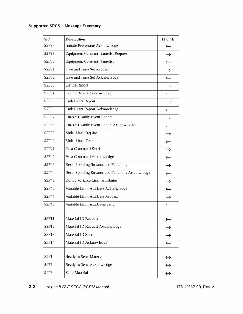
S/F Description H ↔E
SxF0 Abort Transaction →<-
S1F1 Are You There Request ↔S1F2 On Line Data ↔S1F3 Selected Equipment Status Report →S1F4 Selected Equipment Status Data ←S1F9 Material Transfer Status Request →S1F10 Material Transfer Status Data ←S1F11 Status Variable Namelist Request →S1F12 Status Variable Namelist Reply ←S1F13 Establish Communication Request ↔S1F14 Establish Communication Data ↔S1F15 Request OFF-LINE →S1F16 OFF-LINE Acknowledge ←S1F17 Request ON-LINE →S1F18 ON-LINE Acknowledge ←
S2F13 Equipment Constant Request →S2F14 Equipment Constant Data ←S2F15 New Equipment Constant Send →S2F16 New Equipment Constant Acknowledge ←S2F17 Date and Time Request ↔S2F18 Date and Time Data ↔S2F21 Remote Command Send →S2F22 Remote Command Acknowledge ←S2F23 Trace Initialize Send →S2F24 Trace Initialize Acknowledge ←S2F25 Loopback Diagnostic Request →S2F26 Loopback Diagnostic Data ←S2F27 Initiate Processing Request →
175-19567-00, Rev. A Aspen II SLE SECS II/GEM Manual 2-1
Supported SECS II Message Summary
S2F28 Initiate Processing Acknowledge ←S2F29 Equipment Constant Namelist Request →S2F30 Equipment Constant Namelist ←S2F31 Date and Time Set Request →S2F32 Date and Time Set Acknowledge ←S2F33 Define Report →S2F34 Define Report Acknowledge ←S2F35 Link Event Report →S2F36 Link Event Report Acknowledge ←S2F37 Enable/Disable Event Report →S2F38 Enable/Disable Event Report Acknowledge ←S2F39 Multi-block Inquire →S2F40 Multi-block Grant ←S2F41 Host Command Send →S2F42 Host Command Acknowledge ←S2F43 Reset Spooling Streams and Functions →S2F44 Reset Spooling Streams and Functions Acknowledge ←S2F45 Define Variable Limit Attributes →S2F46 Variable Limit Attribute Acknowledge ←S2F47 Variable Limit Attribute Request →S2F48 Variable Limit Attributes Send ←
S3F11 Material ID Request ←S3F12 Material ID Request Acknowledge →S3F13 Material ID Send →S3F14 Material ID Acknowledge ←
S4F1 Ready to Send Material ↔S4F2 Ready to Send Acknowledge ↔S4F3 Send Material ↔
S/F Description H ↔E
2-2 Aspen II SLE SECS II/GEM Manual 175-19567-00, Rev. A

Supported SECS II Message Summary
S4F5 Handshake Complete ↔S4F7 Not Ready to Send ↔S4F9 Stuck in Send ←S4F11 Stuck in Receiver ←S4F13 Send Incomplete Timeout ←S4F15 Material Received ←S4F17 Request to Receive Material ↔S4F18 Request to Receive Material Acknowledge ↔
S5F1 Alarm Report Send ←S5F2 Alarm Report Acknowledge →S5F3 Enable/Disable Alarm Send →S5F4 Enable/Disable Alarm Acknowledge ←S5F5 List Alarm Request →S5F6 Alarm Data ←S5F7 List Enabled Alarm Request →S5F8 List Enabled Alarm ←
S6F1 Trace Data Send ←S6F2 Trace Data Acknowledge →S6F3 Discrete Variable Data Send ←S6F4 Discrete Variable Data Acknowledge →S6F5 Multi-block Data Send Inquire ←S6F6 Multi-block Grant →S6F9 Formatted Variable Send ←S6F10 Formatted Variable Acknowledge →S6F11 Event Report Send ←S6F12 Event Report Acknowledge →S6F13 Annotated Event Report Send ←S6F14 Annotated Event Report Acknowledge →
S/F Description H ↔E
175-19567-00, Rev. A Aspen II SLE SECS II/GEM Manual 2-3

Supported SECS II Message Summary
S6F15 Event Report Request →S6F16 Event Report Data ←S6F17 Annotated Event Report Request →S6F18 Annotated Event Report Data ←S6F19 Individual Report Request →S6F20 Individual Report Data ←S6F21 Annotated Individual Report Request →S6F22 Annotated Individual Report Data ←S6F23 Request Spooled Data →S6F24 Request Spooled Data Acknowledge ←
S7F1 Process Program Load Inquire →S7F2 Process Program Load Grant ←S7F3 Process Program Send →S7F4 Process Program Acknowledge ←S7F5 Process Program Request →S7F6 Process Program Data ←S7F7 Process Program ID Request ←S7F8 Process Program ID Data →S7F17 Delete Process Program Send →S7F18 Delete Process Program Acknowledge ←S7F19 Current EPPID Request →S7F20 Current EPPID Data ←S7F23 Formatted Process Program Send →S7F24 Formatted Process Program Acknowledge ←S7F25 Formatted Process Program Request →S7F26 Formatted Process Program Data ←S7F27 Process Program Verification Send →S7F28 Process Program Verification Acknowledge ←
S/F Description H ↔E
2-4 Aspen II SLE SECS II/GEM Manual 175-19567-00, Rev. A

Supported SECS II Message Summary
S7F65 Route Upload Request →S7F66 Route Upload ←S7F67 Route Download →S7F68 Route Download Acknowledge ←S7F71 Non-Route Process Program Load Inquire →S7F72 Non-Route Process Program Load Grant ←S7F73 Non-Route Formatted Process Program Send →S7F74 Non-Route Formatted Process Program Acknowledge ←S7F75 Non-Route Formatted Process Program Request →S7F76 Non-Route Formatted Process Program Data ←
S9F1 Unrecognized Device ID ←S9F3 Unrecognized Stream Type ←S9F5 Unrecognized Function Type ←S9F7 Illegal Data ←S9F9 Transaction Timer Timeout ←S9F11 Data Too Long ←S9F13 Conversation Timeout ←
S10F1 Terminal Request ←S10F2 Terminal Request Acknowledge →S10F3 Terminal Display Single →S10F4 Terminal Display Single Acknowledge ←
S/F Description H ↔E
175-19567-00, Rev. A Aspen II SLE SECS II/GEM Manual 2-5
Supported SECS II Message Summary
2-6 Aspen II SLE SECS II/GEM Manual 175-19567-00, Rev. A

3.0 Supported SECS II Messages
3.1 SxF0
SxF0 Abort Transaction S,H→→→→E
If the Aspen equipment receives a function zero message, it will drop the aborted spooled message.
3.2 S1Fx
S1F1 Are You There Request (R) S,H↔↔↔↔E, reply
Establishes if the equipment is online.
Structure: Header only
S1F2 On Line Data (D) S,H↔↔↔↔E
Data signifying that the equipment is alive.
Structure:L,2
1. <MDLN> (ASCII)2. <SOFTREV> (ASCII)
Exceptions: 1. The host sends a zero length list to Aspen.2. If AS1F2 is included with the SECS protocol, the SIB will reply with a single-byte binary
message.
Note SOFTREV is the SECS II module’s software revision, not the Aspen module.
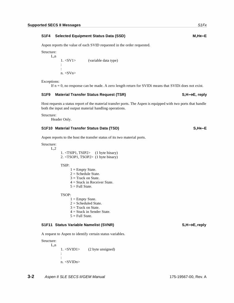
S1F3 Selected Equipment Status Request (SSR) S,H→→→→E, reply
Request for the equipment to report selected status variable IDs. The SVID’s numbers are the same as the VIDs shown in Appendix D.
Structure: L,n
1. <SVID1> (2 byte unsigned) ::n. <SVIDn>
Exception:A zero length list (n = 0) means report all SVIDs.Aspen
Note The SLE software cannot support reporting all SVIDs because the size of the message will exceed the buffer storage in the SECS II card. Send for the SVIDs in groups of 100. There are over 250 SVIDs.
175-19567-00, Rev. A Aspen II SLE SECS II/GEM Manual 3-1
Supported SECS II Messages S1Fx
S1F4 Selected Equipment Status Data (SSD) M,H←←←←E
Aspen reports the value of each SVID requested in the order requested.
Structure:L,n
1. <SV1> (variable data type)::n. <SVn>
Exceptions:If n = 0, no response can be made. A zero length return for SVIDi means that SVIDi does not exist.
S1F9 Material Transfer Status Request (TSR) S,H→→→→E, reply
Host requests a status report of the material transfer ports. The Aspen is equipped with two ports that handle both the input and output material handling operations.
Structure: Header Only.
S1F10 Material Transfer Status Data (TSD) S,H←←←←E
Aspen reports to the host the transfer status of its two material ports.
Structure: L,2
1. <TSIP1, TSIP2> (1 byte binary)2. <TSOP1, TSOP2> (1 byte binary)
TSIP:1 = Empty State.2 = Schedule State.3 = Track on State.4 = Stuck in Receiver State.5 = Full State.
TSOP:1 = Empty State.2 = Scheduled State.3 = Track on State.4 = Stuck in Sender State.5 = Full State.
S1F11 Status Variable Namelist (SVNR) S,H→→→→E, reply
A request to Aspen to identify certain status variables.
Structure: L,n
1. <SVID1> (2 byte unsigned): : n. <SVIDn>
3-2 Aspen II SLE SECS II/GEM Manual 175-19567-00, Rev. A
S1Fx Supported SECS II Messages
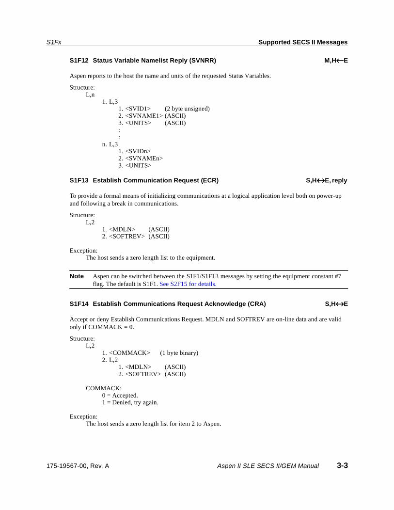
S1F12 Status Variable Namelist Reply (SVNRR) M,H ←←←←E
Aspen reports to the host the name and units of the requested Status Variables.
Structure: L,n
1. L,3 1. <SVID1> (2 byte unsigned)2. <SVNAME1> (ASCII)3. <UNITS> (ASCII): :
n. L,3 1. <SVIDn> 2. <SVNAMEn> 3. <UNITS>
S1F13 Establish Communication Request (ECR) S,H ↔↔↔↔E, reply
To provide a formal means of initializing communications at a logical application level both on power-up and following a break in communications.
Structure: L,2
1. <MDLN> (ASCII) 2. <SOFTREV> (ASCII)
Exception: The host sends a zero length list to the equipment.
Note Aspen can be switched between the S1F1/S1F13 messages by setting the equipment constant #7 flag. The default is S1F1. See S2F15 for details.
S1F14 Establish Communications Request Acknowledge (CRA) S,H↔↔↔↔E
Accept or deny Establish Communications Request. MDLN and SOFTREV are on-line data and are valid only if COMMACK = 0.
Structure: L,2
1. <COMMACK> (1 byte binary)2. L,2
1. <MDLN> (ASCII)2. <SOFTREV> (ASCII)
COMMACK: 0 = Accepted.1 = Denied, try again.
Exception: The host sends a zero length list for item 2 to Aspen.
175-19567-00, Rev. A Aspen II SLE SECS II/GEM Manual 3-3
Supported SECS II Messages S2Fx
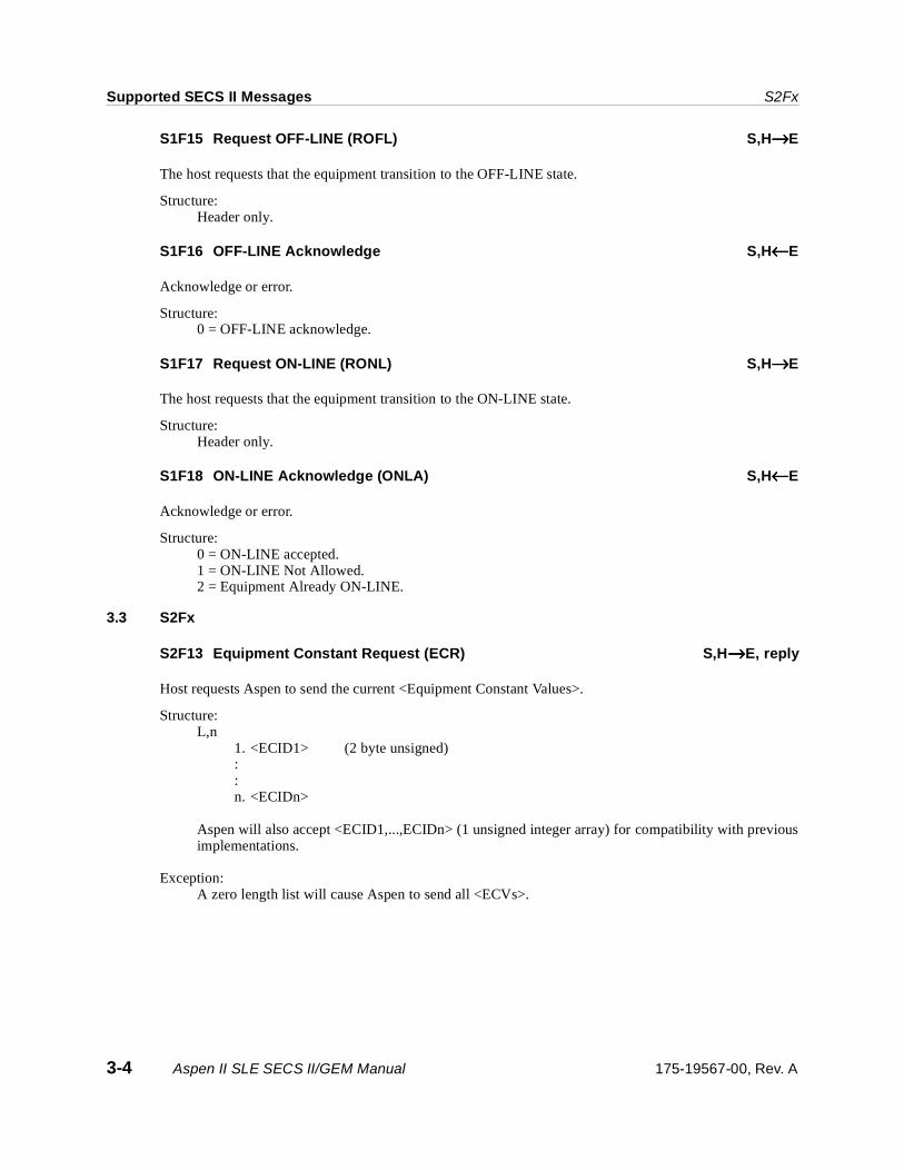
S1F15 Request OFF-LINE (ROFL) S,H→→→→E
The host requests that the equipment transition to the OFF-LINE state.
Structure:Header only.
S1F16 OFF-LINE Acknowledge S,H←←←←E
Acknowledge or error.
Structure:0 = OFF-LINE acknowledge.
S1F17 Request ON-LINE (RONL) S,H→→→→E
The host requests that the equipment transition to the ON-LINE state.
Structure:Header only.
S1F18 ON-LINE Acknowledge (ONLA) S,H←←←←E
Acknowledge or error.
Structure:0 = ON-LINE accepted.1 = ON-LINE Not Allowed.2 = Equipment Already ON-LINE.
3.3 S2Fx
S2F13 Equipment Constant Request (ECR) S,H→→→→E, reply
Host requests Aspen to send the current <Equipment Constant Values>.
Structure: L,n
1. <ECID1> (2 byte unsigned): : n. <ECIDn>
Aspen will also accept <ECID1,...,ECIDn> (1 unsigned integer array) for compatibility with previousimplementations.
Exception: A zero length list will cause Aspen to send all <ECVs>.
3-4 Aspen II SLE SECS II/GEM Manual 175-19567-00, Rev. A
S2Fx Supported SECS II Messages
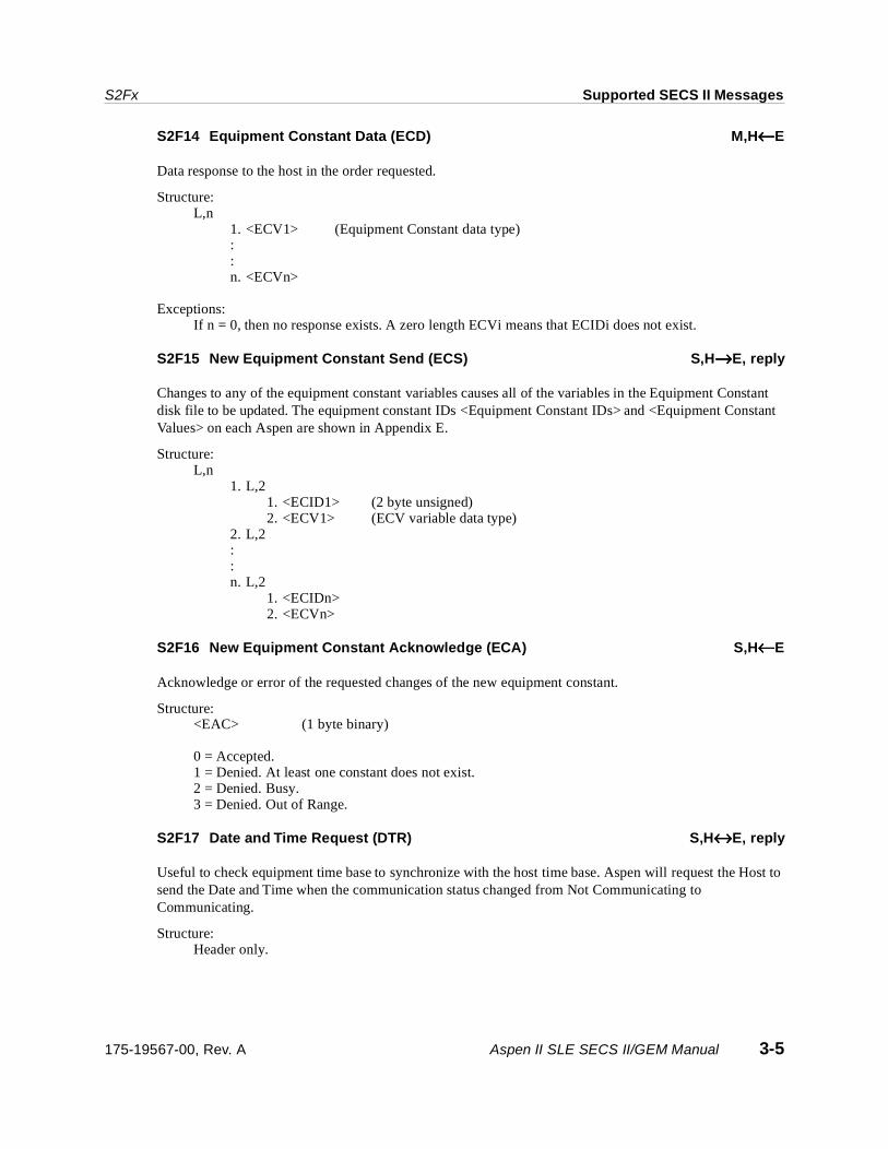
S2F14 Equipment Constant Data (ECD) M,H←←←←E
Data response to the host in the order requested.
Structure:L,n
1. <ECV1> (Equipment Constant data type)::n. <ECVn>
Exceptions:If n = 0, then no response exists. A zero length ECVi means that ECIDi does not exist.
S2F15 New Equipment Constant Send (ECS) S,H→→→→E, reply
Changes to any of the equipment constant variables causes all of the variables in the Equipment Constant disk file to be updated. The equipment constant IDs <Equipment Constant IDs> and <Equipment Constant Values> on each Aspen are shown in Appendix E.
Structure: L,n
1. L,2 1. <ECID1> (2 byte unsigned)2. <ECV1> (ECV variable data type)
2. L,2 ::n. L,2
1. <ECIDn> 2. <ECVn>
S2F16 New Equipment Constant Acknowledge (ECA) S,H←←←←E
Acknowledge or error of the requested changes of the new equipment constant.
Structure: <EAC> (1 byte binary)
0 = Accepted.1 = Denied. At least one constant does not exist.2 = Denied. Busy.3 = Denied. Out of Range.
S2F17 Date and Time Request (DTR) S,H↔↔↔↔E, reply
Useful to check equipment time base to synchronize with the host time base. Aspen will request the Host to send the Date and Time when the communication status changed from Not Communicating to Communicating.
Structure: Header only.
175-19567-00, Rev. A Aspen II SLE SECS II/GEM Manual 3-5

Supported SECS II Messages S2Fx
S2F18 Date and Time Data (DTD) S,H↔↔↔↔E
Actual time data.
Structure: <TIME> (12 byte ASCII “yymmddhhmmss” in case EC13 is set to 0,
16 byte ASCII “yyyymmddhhmmsscc” in case EC13 is set to 1.)
S2F21 Remote Command Send (RCS) S,H→→→→E, reply
While in remote mode, the host can command the equipment to pause its operations, continue its operations, or abort its operations. If an abort command is received, the equipment will be switched back to engineering mode and all operation will stop. To restart the equipment for processing, the equipment has to be returned to remote mode and a S2F27 message used to initiate processing.
Structure:<RCMD> (1 byte unsigned)
1 = Abort.2 = Continue.4 = Pause.6 = Stop (Set inner wafer count to 0).
S2F22 Remote Command Acknowledge (RCA) S,H←←←←E
Acknowledge or error.
Structure: <CMDA> (1 byte binary)
0 = Completed.2 = Can not perform now. Not in remote mode.4 = Recipe name not found.
S2F23 Trace Initialize Send (TIS) S,H→→→→E, reply
Trace initialize send allows the host to describe a timed data acquisition routine to the Aspen. The host sends the trace identification <TRID>, data sample period <DSPER>, “hhmmss”, total samples <TOTSMP>, and report group size <REPGSZ>. The report group size is defaulted to <1>. The status variables may be selected from Appendix D.
Structure: L, 5
1. <TRID> (2 byte unsigned) 2. <DSPER> (6 byte ASCII) 3. <TOTSMP> (2 byte unsigned) 4. <REPGSZ> (2 byte unsigned) 5. L,n
1. <SVID1> (2 byte unsigned) 2. <SVID2> : : n. <SVIDn>
3-6 Aspen II SLE SECS II/GEM Manual 175-19567-00, Rev. A

S2Fx Supported SECS II Messages
S2F24 Trace Initialize Acknowledge (TIA) S,H←←←←E
Acknowledge or error.
Structure: <TIAACK> (1 byte binary)
0 = OK.1 = Too many SVIDs.2 = No more trace space.
S2F25 Loopback Diagnostic Request (LDR) S,H→→→→E, reply
A diagnostic message for checkout of protocol and communication circuits. The ASCII string sent is echoed back.
Structure: <ABS> (binary array)
S2F26 Loopback Diagnostic Data (LDD) S,H←←←←E
The echoed ASCII string.
Structure: <ABS> (binary array)
S2F27 Initiate Processing Request (IPR) S,H→→→→E, reply
The Aspen equipment is required to be in the remote mode before it can accept this command. The host can use this message to start the processing of a single batch of wafers that have been loaded into the outer cassette nests. This single message can be used in place of the S3F11 and S7F7 messages which also provides material id and processing recipe information to the Aspen equipment. It is assumed that a maximum of two cassettes will make up a batch of wafers.
Structure: L,3
1. <LOC> (1 byte binary) 2. <PPID> (25 byte ASCII)
L,n 1. <MID1> (16 byte ASCII max.): : n. <MIDn>
LOC =0 = Left CassetteLOC =1 = Right CassetteLOC =2 = Both Cassettes
Exceptions:A zero length PPID indicates no process program is being specified and the equipment is to take thecurrent outer recipe number. A zero length MID list indicates no MID is to be associated with thematerial to be processed.
175-19567-00, Rev. A Aspen II SLE SECS II/GEM Manual 3-7
Supported SECS II Messages S2Fx
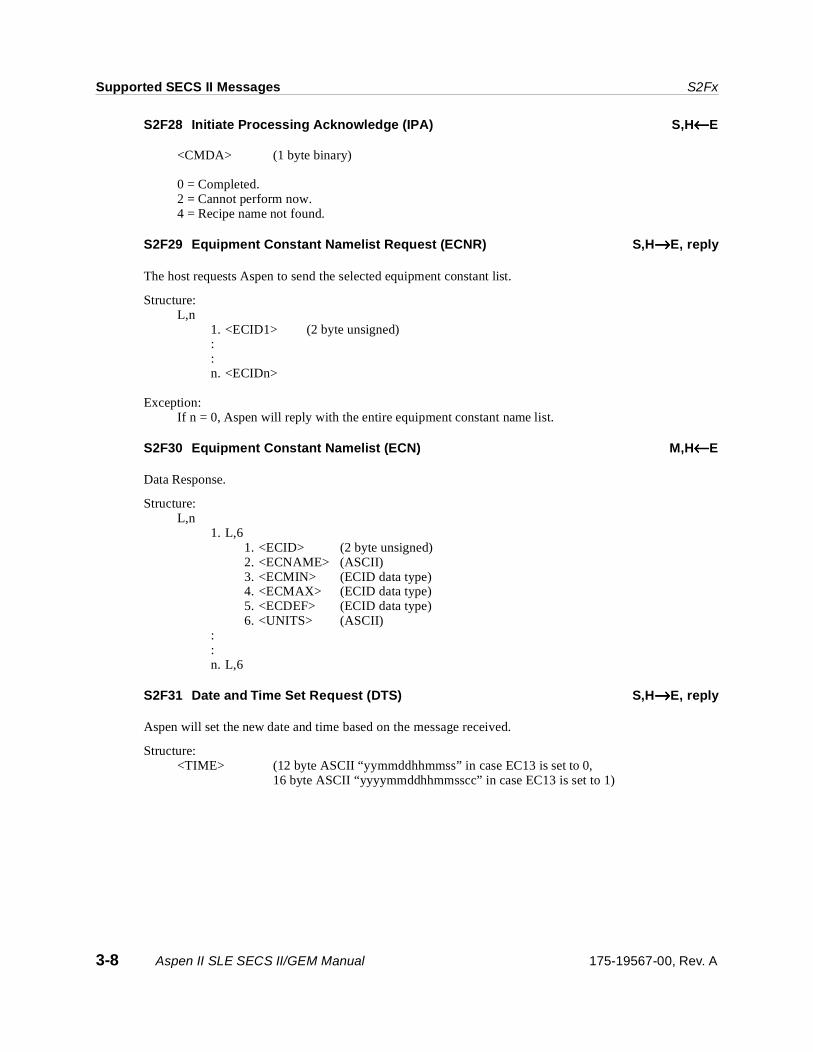
S2F28 Initiate Processing Acknowledge (IPA) S,H←←←←E
<CMDA> (1 byte binary)
0 = Completed.2 = Cannot perform now.4 = Recipe name not found.
S2F29 Equipment Constant Namelist Request (ECNR) S,H→→→→E, reply
The host requests Aspen to send the selected equipment constant list.
Structure: L,n
1. <ECID1> (2 byte unsigned)::n. <ECIDn>
Exception: If n = 0, Aspen will reply with the entire equipment constant name list.
S2F30 Equipment Constant Namelist (ECN) M,H←←←←E
Data Response.
Structure: L,n
1. L,6 1. <ECID> (2 byte unsigned) 2. <ECNAME> (ASCII) 3. <ECMIN> (ECID data type) 4. <ECMAX> (ECID data type) 5. <ECDEF> (ECID data type) 6. <UNITS> (ASCII)
::n. L,6
S2F31 Date and Time Set Request (DTS) S,H→→→→E, reply
Aspen will set the new date and time based on the message received.
Structure: <TIME> (12 byte ASCII “yymmddhhmmss” in case EC13 is set to 0,
16 byte ASCII “yyyymmddhhmmsscc” in case EC13 is set to 1)
3-8 Aspen II SLE SECS II/GEM Manual 175-19567-00, Rev. A

S2Fx Supported SECS II Messages
S2F32 Date and Time Set Acknowledge (DTA) S,H←←←←E
Acknowledge or error.
Structure: <TIACK> (1 byte binary)
0 = OK.1 = Error.
S2F33 Define Report (DR) M,H→→→→E, reply
The define report message allows the host to describe a group of reports to the Aspen. The reports include <Report ID> and <Variable Data ID>. The variable data is collected and updated by the Aspen throughout its operation. The type of report is determined by the <Equipment Constant ID> No. 1. If it is set to true, it means that an annotated event report (S6F13) will be sent to the host. If it is set to false, an un-annotated (S6F11) event report will be sent. If this is a multi-block message, then the S2F39/S2F40 Inquire/Grant transaction is required.
Structure: L,2
1. <DATAID> (2 byte unsigned)2. L,a
1. L,2 1. <RPTID> (2 byte unsigned)2. L,b
1. <VID1> (2 byte unsigned)::b. <VIDb>
::a. L,2
1. <RPTID>2. L,c
1. <VID1>::c. <VIDc>
Exceptions: 1. If a = 0, a list of zero length following <DataID>, will delete all report definitions and associated
links.2. If b = 0, a zero length following <Report ID>, deletes report type <Report ID> and all <Collected
Event ID> links to this <Report ID> will be eliminated.
175-19567-00, Rev. A Aspen II SLE SECS II/GEM Manual 3-9

Supported SECS II Messages S2Fx
S2F34 Define Report Acknowledge (DRA) S,H←←←←E
Acknowledge or error. If an error condition is detected, the entire message is rejected.
Structure: <DRACK> (1 byte binary)
0 = Defined Report Accepted.1 = Insufficient Space for Report.2 = Invalid Report Format.3 = Duplicated Report ID.4 = At least one VID does not exist.5 = At least one RPTID does not exist for deletion.
S2F35 Link Event Report (LER) M,H→→→→E, reply
Link Report message allows the host to link Collected Event IDs, <Collected Event ID>, to the various defined reports. Linked event reports will default to disabled. If this message is a multi-block message, the S2F39/S2F40 Inquire/Grant transaction is required.
Structure: L,2
1. <DATAID> (2 byte unsigned)2. L,a
1. L,2 1. <CEID1> (2 byte unsigned) 2. L,b
1. <RPTID1> (2 byte unsigned)::b. <RPTIDb>
: :
a. L,21. <CEIDa>2. L,c
1. <RPTID1>::c. <RPTIDc>
Exception: A list of zero length following DATAID deletes all links to all events.A list of zero length following CEID deletes all report links to that event.
3-10 Aspen II SLE SECS II/GEM Manual 175-19567-00, Rev. A

S2Fx Supported SECS II Messages
S2F36 Link Event Report Acknowledge (LERA) S,H←←←←E
Acknowledge or error.
Structure: <LRACK> (1 byte binary)
0 = CEID link accepted.1 = Insufficient space.2 = Invalid CEID format.3 = At least one CEID link duplicated.4 = At least one CEID does not exist.5 = At least one RPTID does not exist.6 = Invalid DATAID.
S2F37 Enable/Disable Event Report (EDER) S,H→→→→E, reply
Message allows the host to enable or disable reporting for a group of events (Collected Event IDs) by setting Collected Event Enable/Disable to true for enabling or false for disabling.
Structure: L,2
1. <CEED> (1 byte boolean)2. L,n
1. <CEID1> (2 byte unsigned)::n. <CEIDn>
Exception: A list of zero length following <CEED> means all CEIDs.
S2F38 Enable/Disable Event Report Acknowledge (EERA) S,H←←←←E
Acknowledge or error.
Structure: <LRACK> (1 byte binary)
0 = CEED accepted.1 = At least one CEID not found.2 = Invalid format.
S2F39 Multi-Block Inquire (DMI) S,H→→→→E, reply
If an S2F33 or S2F35 message is more than one block, this transaction must precede the message.
Structure: L,2
1. <DATAID> (2 byte unsigned)2. <DATALENGTH> (2 byte integer)
175-19567-00, Rev. A Aspen II SLE SECS II/GEM Manual 3-11
Supported SECS II Messages S2Fx
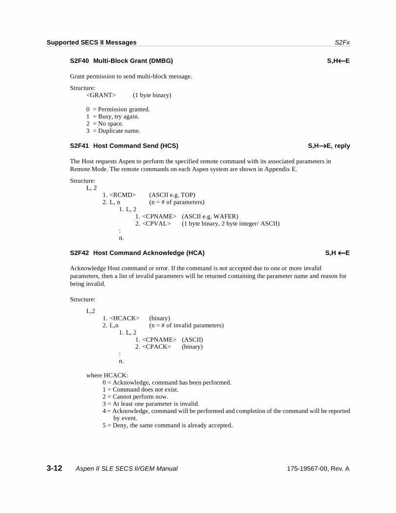
S2F40 Multi-Block Grant (DMBG) S,H←←←←E
Grant permission to send multi-block message.
Structure: <GRANT> (1 byte binary)
0 = Permission granted.1 = Busy, try again.2 = No space.3 = Duplicate name.
S2F41 Host Command Send (HCS) S,H→→→→E, reply
The Host requests Aspen to perform the specified remote command with its associated parameters in Remote Mode. The remote commands on each Aspen system are shown in Appendix E.
Structure:L, 2
1. <RCMD> (ASCII e.g. TOP)2. L, n (n = # of parameters)
1. L, 21. <CPNAME> (ASCII e.g. WAFER) 2. <CPVAL> (1 byte binary, 2 byte integer/ ASCII)
:n.
S2F42 Host Command Acknowledge (HCA) S,H ←←←←E
Acknowledge Host command or error. If the command is not accepted due to one or more invalid parameters, then a list of invalid parameters will be returned containing the parameter name and reason for being invalid.
Structure:
L,21. <HCACK> (binary)2. L,n (n = # of invalid parameters)
1. L, 21. <CPNAME> (ASCII)2. <CPACK> (binary)
:n.
where HCACK: 0 = Acknowledge, command has been performed.1 = Command does not exist.2 = Cannot perform now.3 = At least one parameter is invalid.4 = Acknowledge, command will be performed and completion of the command will be reported
by event.5 = Deny, the same command is already accepted.
3-12 Aspen II SLE SECS II/GEM Manual 175-19567-00, Rev. A

S2Fx Supported SECS II Messages
CPACK:1 = Parameter Name does not exist.2 = Illegal Value specified for CPVAL.3 = Illegal Format specified for CPVAL.
Exception: If n = 0, a zero length list indicates no invalid parameters.
S2F43 Reset Spooling Streams and Functions S,H→→→→E, reply
This message allows the host to select specific streams and functions to be spooled whenever spooling is active. Alarm reporting (S5F1, S5F73) will not be spooled and will be sent to the host immediately. The following are the accepted streams and functions:
Structure: L,m
1. L,2 1. <STRID> (1 byte unsigned) 2. L,n
1. <FCNID1> (1 byte unsigned) : n. <FCNIDn>
m.L,2
Exceptions: 1. A zero length list, m = 0, turns off spooling for all streams and functions.2. A zero length list, n = 0, turns on all functions for the associated stream. A defined list of functions
for a stream in this message will replace any previously selected function.
Streams Functions3 114 1, 176 1, 3, 11, 137 7
175-19567-00, Rev. A Aspen II SLE SECS II/GEM Manual 3-13

Supported SECS II Messages S2Fx
S2F44 Reset Spooling Acknowledge (RSA) M,H←←←←E
Acknowledge or error. If an error condition is detected, the entire message is rejected.
Structure:L,2
1. <RSACK> (1 byte binary)2. L,m (m = # of invalid streams or functions)
1. L,31. <STRID> (1 byte unsigned)2. <STRACK1> (1 byte binary)3. L,n
1. <FCNID> (1 byte unsigned):
RSACK: 0 = Acknowledge, spooling setup accepted.1 = Spooling setup rejected.
STRACK: 1 = Spooling not allowed for stream.2 = Stream unknown.3 = Unknown function specified for this stream.4 = Secondary function specified for this stream.
Exception: If RSACK = 0, a zero length list, m = 0 indicates no invalid stream or functions.
S2F45 Define Variable Limit Attributes (DVLA) M,H→→→→E, reply
Allows the host to define or modify an existing equipment variable limit definition. Each limit defined will overwrite that limit's previous definition. LIMITID should be a continuous number starting from 1 to 10.
The processing VID variables that are supported are: #11 First Chamber RF Power#13 First Chamber Process Pressure#14 First Chamber Gas1#15 First Chamber Gas 2#16 First Chamber Gas 3#307 First Chamber Gas4#308 First Chamber Gas 5#309 First Chamber Gas 6#310 First Chamber Gas 7#311 First Chamber Gas 8#17 First Chamber Temperature#61 Second Chamber RF Power#63 Second Chamber Process Pressure #64 Second Chamber Gas1 #65 Second Chamber Gas 2#66 Second Chamber Gas 3 #407 Second Chamber Gas4#408 Second Chamber Gas 5#409 Second Chamber Gas 6#410 Second Chamber Gas 7#411 SecondChamber Gas 8#67 Second Chamber Temperature
3-14 Aspen II SLE SECS II/GEM Manual 175-19567-00, Rev. A

S2Fx Supported SECS II Messages
Structure: L,2
1. <DATAID> (2 byte unsigned) 2. L,m (m = # of variables in this definition)
1. L,2 1. <VID> (2 byte unsigned) 2. L,n (n = # of limits for VID)
1. L,2 1. <LIMITID1> (1 byte binary)2. L,p
1. <UPPER BOUND> (VID type) 2. <LOWER BOUND> (VID type)
: n. L,2
1. <LIMITIDn> 2. L,p
1. <UPPER BOUND>2. <LOWER BOUND>
m.L,2 1. <VIDm>
Exceptions: 1. m = 0 sets all limits values for all monitored VIDs to “undefined”.2. n = 0 sets all limit values for that VID to “undefined”.3. A zero length list, p = 0, sets that limit to “undefined”.
S2F46 Variable Limit Attribute Acknowledge (VLAA) M,H←←←←E
Acknowledge definition of variable limit attributes or error. If DVLA is not accepted due to one or more invalid parameters, then a list of invalid parameters will be returned containing the variable limit attribute and reason for being invalid. If an error condition is detected, the entire message is rejected.
Structure: L,2
1. <VLAACK> (1 byte binary)2. L,m (m = number of invalid parameters).
1. L,3 1. <VID> (2 byte unsigned) 2. <LVACK> (1 byte binary)3. L,n {n = 0 or 2}
1. <LIMITID1> (1 byte binary) 2. <LIMITACK> (1 byte binary)
VLAACK: 0 = Acknowledge, command will be performed.1 = Limit attribute definition error.2 = Cannot perform now.
LVACK: Reason of error1 = Variable does not exist.2 = Variable has no limits capability.3 = Variable repeated in message.4 = Limit value error as described in LIMITACK.
175-19567-00, Rev. A Aspen II SLE SECS II/GEM Manual 3-15
Supported SECS II Messages S2Fx
LIMITID: First limit in error for VID.
LIMITACK: Reason of error for LIMITID.1 = LIMITID does not exist.2 = UPPERDB > LIMITMAX.3 = LOWERDB < LIMITMIN.4 = UPPERDB < LOWERDB.5 = Illegal format specified for UPPERDB or LOWERDB.7 = Duplicate limit definition for this variable.
Exceptions:1. A zero length list, m = 0, indicates no invalid variable attributes were found.2. A zero length list, n = 0, indicates that there were no invalid limit values.
S2F47 Variable Limit Attribute Request (VLAR) S,H→→→→E, reply
This message allows the host to query the equipment for current variable limit attribute definitions.
Structure:L,m (m = #VIDs in this request)
1. <VID1> (2 byte unsigned)::m.<VIDm>
Exception:A zero length list, m = 0, requests a list of all VID values that can have variable limit attributes.
S2F48 Variable Limit Attributes Send (VLAS) M,H←←←←E
Equipment sends values of requested variable limit attribute definitions in the order requested.
Structure:L,m (m = # VIDs in this request)
1. L,2 1. <VID> (2 byte unsigned) 2. L, p {p = 0,4}
1. <UNITS1> (ASCII)2. <LIMITMIN1> (VID data type)3. <LIMITMAX1> (VID data type) 4. L,n (n = # of limits for VID)
1. L,3 1. <LIMITID1> (1 byte binary)2. <UPPER BOUND> (VID type) 3. <LOWER BOUND> (VID type)
: n. L,3
1. <LIMITIDn> 2. <UPPER BOUND> 3. <LOWER BOUND>
:m.L,2
1. <VIDm>
3-16 Aspen II SLE SECS II/GEM Manual 175-19567-00, Rev. A

S3Fx Supported SECS II Messages
Exceptions: 1. p = 0 indicates that the corresponding VID can have no limit definition.2. n = 0 means no limits are currently defined for the specified variable.
3.4 S3Fx
S3F11 Material ID Request (MIDR) S,H ←←←←E, reply
While in the remote mode, Aspen requests material id information from the host with the S3F11 function call. If the S2F27 Initiate Processing Request has already been received or is being received, then the Material ID Request will not be needed. The Aspen equipment has two ports with port ID 1 for the left cassette and ID 2 for the right cassette.
Structure: <PTN> (1 byte binary)
See Appendix E.
S3F12 Material ID Request Acknowledge (MIRA) S,H →→→→E
The host acknowledge the request for the Material ID.
Structure: L,3
1. <PTN> (1 byte binary)2. <MIDRA> (1 byte binary)3. <MID> (16 byte ASCII max.)
MIDRA: 0 = Acknowledge, MID follows.1 = Acknowledge, will not send MID.2 = Acknowledge, will send MID later in S3F13 message.
Note For all cases except MIDRA = 0, the <MID> will be ignored by the receiver of message S3F12. When MIDRA = 0, a zero length MID indicates that no MID is available.
See Appendix E.
S3F13 Material ID Send S,H →→→→E, reply
The host sends the Material ID of material at the specified port. This is the case where a request/acknowledge/send/acknowledge conversation is used for S3F11 and S3F13.
Structure: L,2
1. <PTN> (1 byte binary)2. <MID> (16 byte ASCII max.)
See Appendix E.
175-19567-00, Rev. A Aspen II SLE SECS II/GEM Manual 3-17

Supported SECS II Messages S4Fx
S3F14 Material ID Acknowledge S,H ←←←←E
Acknowledge or error.
Structure: <MIDAC> (1 byte binary)
0 = Accepted.1 = Invalid port number.2 = Material is not present at identified port.>2 = Error.
See Appendix E.
3.5 S4Fx
S4F1 Ready to Send Material (RSN) S,H ↔↔↔↔E, reply
The sender advises the receiver that some material is awaiting transfer.
Structure: L,2
1. <PTN> (1 byte binary)2. <MID> (16 byte ASCII max.)
Note If a material ID field message length is zero, the material is unknown to the equipment.
See Appendix E.
S4F2 Ready to Send Acknowledge (RSA) S,H ↔↔↔↔E
Acknowledge or error.
Structure: <RSACK> (1 byte binary)
0 = OK.1 = Invalid port.2 = Port is already occupied.3 = Port is busy, try again later.4 = Aspen Equipment is not in remote mode.
See Appendix E.
S4F3 Send Material (SMN) S,H↔↔↔↔E
The receiver advises the sender that it is ready to receive material.
Structure: L,2
1. <PTN> (1 byte binary) 2. <MID> (16 byte ASCII max.)
See Appendix E.
3-18 Aspen II SLE SECS II/GEM Manual 175-19567-00, Rev. A
S4Fx Supported SECS II Messages
S4F5 Handshake Complete (HCN) S,H ↔↔↔↔E
Aspen advises sender that material has been received or the host advises Aspen that material has been transferred. The sender may now stop its transfer mechanism.
Structure: L,2
1. <PTN> (1 byte binary) 2. <MID> (16 byte ASCII max.)
See Appendix E.
S4F7 Not Ready to Send (ABN) S,H↔↔↔↔E
Sender advises receiver that no material is being sent.
Structure: L,2
1. <PTN> (1 byte binary) 2. <MID> (16 byte ASCII max.)
See Appendix E.
S4F9 Stuck in Sender (SSN) S,H←←←←E
Time between the receipt of the Send Material (SMN) and material leaving Aspen cassette nests exceeded the T1 time-out.
Structure:L,2
1. <PTN> (1 byte binary) 2. <MID> (16 byte ASCII max.)
See Appendix E.
S4F11 Stuck in Receiver (SRN) S,H←←←←E
Time between Send Material (SMN) and the detection of the material at the Aspen cassette nests exceeded T2 time-out.
Structure: L,2
1. <PTN> (1 byte binary) 2. <MID> (16 byte ASCII max.)
See Appendix E.
175-19567-00, Rev. A Aspen II SLE SECS II/GEM Manual 3-19

Supported SECS II Messages S4Fx
S4F13 Send Incomplete Time-Out (SIN) S,H←←←←E
The time between the receipt of the Send Material (SMN) and the receipt of Handshake Complete(HCN) exceeded T3 time-out.
Structure: L,2
1. <PTN> (1 byte binary) 2. <MID> (16 byte ASCII max.)
See Appendix E.
S4F15 Material Received (MRN) S,H ←←←←E
Aspen sends Material Received message to the host.
Structure: L,2
1. <PTN> (1 byte binary) 2. <MID> (16 byte ASCII max.)
See Appendix E.
S4F17 Request to Receive Material (RTR) S,H ↔↔↔↔E, reply
In the remote control mode, the host and the Aspen equipment use this command to initiate a conversation to transfer the material to the specified port.
Structure: L,2
1. <PTN> (1 byte binary) 2. <MID> (16 byte ASCII max.)
Note A zero length MID means equipment doesn’t know MID.
S4F18 Request to Receive Acknowledge (RRA) S,H ↔↔↔↔E
Acknowledge or error.
Structure: <RRACK> (1 byte binary)
0 = Acknowledge.1 = Error.
See Appendix E.
3-20 Aspen II SLE SECS II/GEM Manual 175-19567-00, Rev. A

S5Fx Supported SECS II Messages
3.6 S5Fx
S5F1 Alarm Report Send (ARS) S,H←←←←E, reply
When an enabled alarm occurs, Aspen will send the alarm to the host. Use S5F3 to enable the selected alarms.
Structure: L,3
1. <ALCD> (1 byte binary)2. <ALID> (2 byte unsigned)3. <ALTX> (ASCII)
ALCD: bit 7 set = Alarm occurs.bit 7 clear = Alarm cleared.
S5F2 Alarm Report Acknowledge (ARA) S,H→→→→E
Acknowledge or error.
Structure: <ACKC5> (1 byte binary)
0 = Accepted.>0 = Error, not accepted.
S5F3 Enable/Disable Alarm Send (EAS) S,H→→→→E, reply
The arrival of this message may change the state of the enable alarm bit on the Aspen equipment. The enable bit determines if the alarm will be sent to the host when such an alarm condition changes. The occurrence of an alarm will not be spooled by the Aspen system. The setting or change of alarm bits will be stored on the hard disk and will be retrieved on power-up.
Structure: L,2
1. <ALED> (1 byte binary) 2. <ALID> (2 byte unsigned)
ALED: Bit 8 = 0 means disable alarm.Bit 8 = 1 means enable alarm.
ALID: 1 - 10 = Valid Alarm ID.0 = enable or disable all alarms depending on ALED.
175-19567-00, Rev. A Aspen II SLE SECS II/GEM Manual 3-21
Supported SECS II Messages S5Fx
S5F4 Enable/Disable Acknowledge (EAA) S,H←←←←E
Acknowledge or error.
Structure: <ACKC5> (1 byte binary)
0 = Accepted.>0 = Error, not accepted.
S5F5 List Alarms Request (LAR) S,H→→→→E, reply
This message requests the Aspen equipment to send a list of selected alarms.
Structure: <ALID1,.......,ALIDn> (2 byte unsigned array)
Exception: A zero length item means send all alarms regardless of the state of ALED.
S5F6 List Alarm Data (LAD) M,H←←←←E
This message contains the alarm data known to the equipment.
Structure: L,m
1. L,3 1. <ALCD1> (1 byte binary) 2. <ALID1> (2 byte unsigned) 3. <ALTX1> (ASCII)
: : m.L,3
1. <ALCDm> 2. <ALIDm> 3. <ALTXm>
Exception: If m = 0, no response can be made. A zero length returned for ALCDi or ALTXi means that value doesnot exist.
S5F7 List Enabled Alarm Request (LEAR) S,H→→→→E, reply
List alarms which are enabled.
Structure: Header only.
S5F8 List Enabled Alarm Data (LEAD) M,H←←←←E
This message is similar to S5F6 except that it lists only alarms which are enabled.
Structure: Same as S5F6.
3-22 Aspen II SLE SECS II/GEM Manual 175-19567-00, Rev. A
S6Fx Supported SECS II Messages
3.7 S6Fx
S6F1 Trace Data Send (TDS) S,H←←←←E, reply
When a time-out has occurred on a set trace timer, Aspen will send the identified defined trace to the host.
Structure: L,4
1. <TRID> (2 byte unsigned) 2. <SMPLN> (2 byte unsigned) 3. <STIME> (16 byte ASCII “YYYYMMDDHHMMSSCC”)4. L,n
1. <SV1> (variable data type) : n. <SVn>
Exception:A zero length STIME means no value is given and that the time is to be derived from SMPLN alongwith acknowledge of the request.
S6F2 Trace Data Acknowledge (TDA) S,H→→→→E
Acknowledge or error.
Structure: <ACKC6> (1 byte binary)
0 = Accepted.>0 = Error, not accepted.
S6F3 Discrete Variable Data Send (DVS) M,H←←←←E, reply
This report is defined by a report configuration file which uses a filename “CUSTnn.RPT” where nn is the customer ID number. The customer number is set by using the “edcfg” edit configuration program. The events are enabled and disabled by using the S2F15 message.
The report is sent to the host when an enabled event has occurred and the event report is defined in the report configuration file.
Structure: L,3
1. <DATAID> (2 byte unsigned) 2. <CEID> (2 byte unsigned) 3. L,n
1. L,2 1. <DSID1> (2 byte unsigned) 2. L,m
1. L,2 1. <DVNAME1>(ASCII) 2. <DVVAL1> (variable data type)
2. L,2 : :
175-19567-00, Rev. A Aspen II SLE SECS II/GEM Manual 3-23

Supported SECS II Messages S6Fx
m.L,2 1. <DVNAMEm> 2. <DVVALm>
2. L,2 : : n. L,2
1. <DSIDn> 2. etc.
S6F4 Discrete Variable Data Acknowledge (DVA) S,H→→→→E
Acknowledge or error.
Structure: <ACKC6> (1 byte binary)
0 = Accepted.>0 = Error, not accepted.
S6F5 Multi-Block Data Send Inquire (MBI) S,H←←←←E, reply
The Aspen equipment will send this inquire message to the host if the size of the event data to be sent is larger than one (244 byte) message block.
Structure: L,2
1. <DATAID> (2 byte unsigned) 2. <DATALENGTH> (2 byte integer)
S6F6 Multi-Block Grant (MBG) S,H→→→→E
Grant permission to send.
Structure: <GRANT6> (1 byte binary)
0 = Permission granted.1 = Busy, try again.2 = Not interested.>2 = Other errors.
3-24 Aspen II SLE SECS II/GEM Manual 175-19567-00, Rev. A
S6Fx Supported SECS II Messages
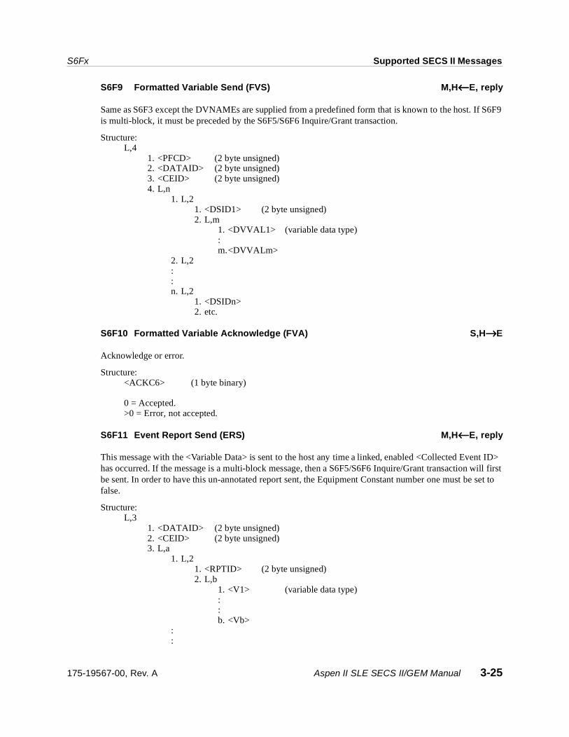
S6F9 Formatted Variable Send (FVS) M,H←←←←E, reply
Same as S6F3 except the DVNAMEs are supplied from a predefined form that is known to the host. If S6F9 is multi-block, it must be preceded by the S6F5/S6F6 Inquire/Grant transaction.
Structure: L,4
1. <PFCD> (2 byte unsigned) 2. <DATAID> (2 byte unsigned)3. <CEID> (2 byte unsigned) 4. L,n
1. L,2 1. <DSID1> (2 byte unsigned) 2. L,m
1. <DVVAL1> (variable data type):m.<DVVALm>
2. L,2 : : n. L,2
1. <DSIDn> 2. etc.
S6F10 Formatted Variable Acknowledge (FVA) S,H→→→→E
Acknowledge or error.
Structure: <ACKC6> (1 byte binary)
0 = Accepted.>0 = Error, not accepted.
S6F11 Event Report Send (ERS) M,H←←←←E, reply
This message with the <Variable Data> is sent to the host any time a linked, enabled <Collected Event ID> has occurred. If the message is a multi-block message, then a S6F5/S6F6 Inquire/Grant transaction will first be sent. In order to have this un-annotated report sent, the Equipment Constant number one must be set to false.
Structure: L,3
1. <DATAID> (2 byte unsigned)2. <CEID> (2 byte unsigned) 3. L,a
1. L,2 1. <RPTID> (2 byte unsigned) 2. L,b
1. <V1> (variable data type): : b. <Vb>
: :
175-19567-00, Rev. A Aspen II SLE SECS II/GEM Manual 3-25

Supported SECS II Messages S6Fx
a. L,2 1. <RPTIDa> 2. L,c
1. <V1> : : c. <Vc>
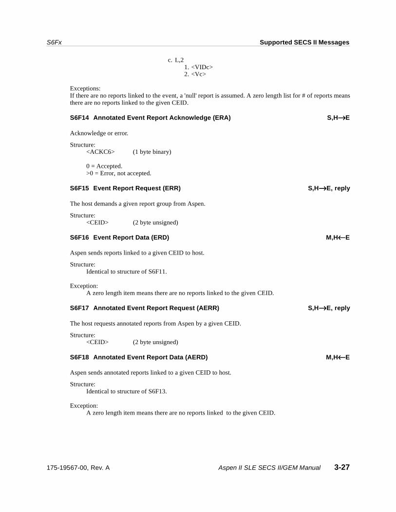
Exceptions: If there are no reports linked to the event, a 'null' report is assumed. A zero length list for # of reportsmeans there are no reports linked to the given CEID.
S6F12 Event Report Acknowledge (ERA) S,H→→→→E
Acknowledge or error.
Structure: <ACKC6> (1 byte binary)
0 = Accepted.>0 = Error, not accepted.
S6F13 Annotated Event Report Send (AERS) S,H←←←←E, reply
This message is the same as S6F11 except that the <Variable IDs> are sent with the data. If this message is a multi-block message, a S6F5/S6F6 Inquire/Grant transaction will first be sent.
Structure: L,3
1. <DATAID> (2 byte unsigned) 2. <CEID> (2 byte unsigned) 3. L,a
1. L,2 1. <RPTID1> (2 byte unsigned) 2. L,b
1. L,2 1. <VID1> (2 byte unsigned) 2. <V1> (variable data type): :
b. L,2 1. <VIDb> 2. <Vb>
: : a. L,2
1. <RPTIDa> 2. L,c
1. L,2 1. <VID1> 2. <V1> : :
3-26 Aspen II SLE SECS II/GEM Manual 175-19567-00, Rev. A
S6Fx Supported SECS II Messages
c. L,2 1. <VIDc> 2. <Vc>
Exceptions: If there are no reports linked to the event, a 'null' report is assumed. A zero length list for # of reports meansthere are no reports linked to the given CEID.
S6F14 Annotated Event Report Acknowledge (ERA) S,H→→→→E
Acknowledge or error.
Structure: <ACKC6> (1 byte binary)
0 = Accepted.>0 = Error, not accepted.
S6F15 Event Report Request (ERR) S,H→→→→E, reply
The host demands a given report group from Aspen.
Structure: <CEID> (2 byte unsigned)
S6F16 Event Report Data (ERD) M,H←←←←E
Aspen sends reports linked to a given CEID to host.
Structure: Identical to structure of S6F11.
Exception: A zero length item means there are no reports linked to the given CEID.
S6F17 Annotated Event Report Request (AERR) S,H→→→→E, reply
The host requests annotated reports from Aspen by a given CEID.
Structure: <CEID> (2 byte unsigned)
S6F18 Annotated Event Report Data (AERD) M,H←←←←E
Aspen sends annotated reports linked to a given CEID to host.
Structure: Identical to structure of S6F13.
Exception: A zero length item means there are no reports linked to the given CEID.
175-19567-00, Rev. A Aspen II SLE SECS II/GEM Manual 3-27
Supported SECS II Messages S6Fx
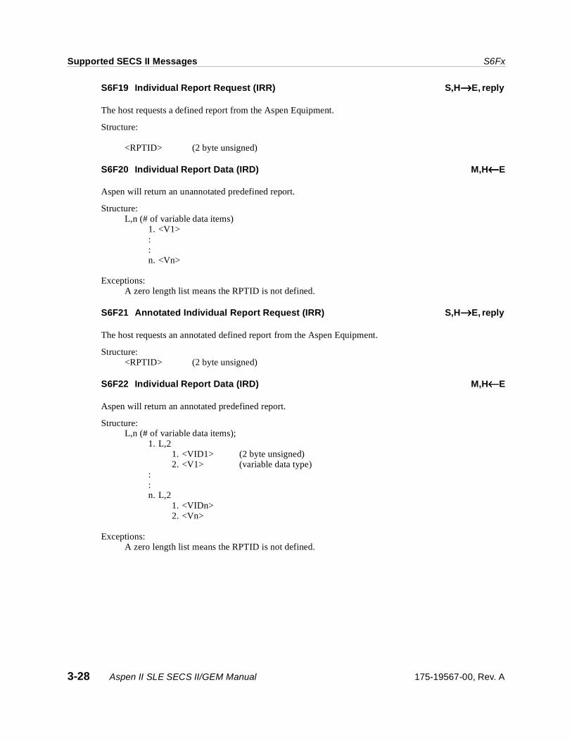
S6F19 Individual Report Request (IRR) S,H→→→→E, reply
The host requests a defined report from the Aspen Equipment.
Structure:
<RPTID> (2 byte unsigned)
S6F20 Individual Report Data (IRD) M,H←←←←E
Aspen will return an unannotated predefined report.
Structure: L,n (# of variable data items)
1. <V1> : : n. <Vn>
Exceptions: A zero length list means the RPTID is not defined.
S6F21 Annotated Individual Report Request (IRR) S,H→→→→E, reply
The host requests an annotated defined report from the Aspen Equipment.
Structure: <RPTID> (2 byte unsigned)
S6F22 Individual Report Data (IRD) M,H←←←←E
Aspen will return an annotated predefined report.
Structure: L,n (# of variable data items);
1. L,2 1. <VID1> (2 byte unsigned) 2. <V1> (variable data type)
: : n. L,2
1. <VIDn> 2. <Vn>
Exceptions: A zero length list means the RPTID is not defined.
3-28 Aspen II SLE SECS II/GEM Manual 175-19567-00, Rev. A

S7Fx Supported SECS II Messages
S6F23 Request Spooled Data (RSD) S,H →→→→E, reply
This message allows the host to request transmission or deletion of the spooled data that the Aspen equipment has to send.
Structure: <RSDC> (1 byte unsigned)
0 = Transmit Spooled Messages.1 = Purge Spooled Messages.
S6F24 Request Spooled Data Acknowledgment Send S,H ←←←←E
Acknowledge or error.
Structure: <RSDA> (1 byte binary)
0 = Accepted.1 = Denied, busy, try later.2 = Denied, spool data does not exist.
3.8 S7Fx
S7F1 Process Program Load Inquire (PPI) S,H →→→→E, reply
This message is used to initiate a recipe program transfer between the host and the Aspen equipment.
Structure.
L,2 1. <PPID> (25 byte ASCII) 2. <LENGTH> (2 byte unsigned)
S7F2 Process Program Load Grant (PPG) S,H←←←←E
This message gives permission for the process recipe program to be loaded.
Structure: <PPGNT> (1 byte binary)
0 = OK to download recipe file to Aspen.1 = No space for the recipe file. Must delete a recipe first.2 = Invalid PPID.4 = Aspen is busy, try later.5 = Mismatched Recipe Name.
Note The recipe is assumed to be returned to the equipment in the same format as it was given to the host.
See Appendix G for program body description.
175-19567-00, Rev. A Aspen II SLE SECS II/GEM Manual 3-29

Supported SECS II Messages S7Fx
S7F3 Process Program Send (PPS) S,H →→→→E, reply
The program is sent. If S7F3 is multi-block, it must be preceded by the S7F1/S7F2 Inquire/Grant transaction.
Structure: L,2
1. <PPID> (25 byte ASCII)2. <PPBODY> (ASCII)
S7F4 Process Program Acknowledge (PPA) S,H ←←←←E
Acknowledge or error.
Structure: <ACKC7> (1 byte binary)
0 = Accepted.1 = Permission not granted.4 = Process Program ID not found.5 = Mode not supported.6 = Other error.
S7F5 Process Program Request (PPR) S,H →→→→E, reply
This message requests that a process recipe program be uploaded to the host.
Structure: <PPID> (25 byte ASCII)
S7F6 Process Program Data (PPD) M,H←←←←E
This message is used to transfer a process program.
Structure: L,2
1. <PPID> (25 byte ASCII)2. <PPBODY> (ASCII)
Exception: A zero length list means request denied.
S7F7 Process Program ID Request (PIR) S,H ←←←←E, reply
This message is used when Aspen is in the remote mode to request a process program for use on the material identified.
Structure: <MID> (16 byte ASCII max.)
See Appendix E.
3-30 Aspen II SLE SECS II/GEM Manual 175-19567-00, Rev. A

S7Fx Supported SECS II Messages
S7F8 Process Program ID Data (PID) S,H→→→→E
The host transmits a single matrix entry in response to S7F7.
Structure: L,2
1. <PPID> (25 byte ASCII)2. <MID> (16 byte ASCII max.)
See Appendix E.
S7F17 Delete Process Program Send (DPS) S,H→→→→E, reply
This message requests that a set of recipe programs be deleted from the Aspen equipment. Aspen accepts a <n> item list of ASCII format <Recipe Program Names>.
Structure: L,n
1. <PPID1> (25 byte ASCII): : n. <PPIDn>
Note If n = 0, Aspen will ignore this message and response with permission not granted.
S7F18 Delete Process Program Acknowledge (DPA) S,H←←←←E
Acknowledge or error.
Structure: <ACKC7> (1 byte binary)
0 = Accepted.1 = Permission not granted.
Permission not granted implies that the requested recipe name did not exist.
S7F19 Current EPPD Request (RER) S,H→→→→E, reply
This message is used to request the transmission of the Aspen recipe program directory.
Structure: Header only.
S7F20 Current EPPD Data (RED) S,H←←←←E
Aspen responds with a list of 99 recipe names.
Structure: L,n
1. <PPID1> (25 byte ASCII) :n. <PPIDn>
175-19567-00, Rev. A Aspen II SLE SECS II/GEM Manual 3-31

Supported SECS II Messages S7Fx
S7F23 Formatted Process Program Send (FPS) M,H →→→→E, reply
This message allows movement of formatted process programs from host to equipment. If S7F23 is a multi-block, it must be preceded by the S7F1/F2 Inquire/Grant.
Use below structure to download by name or number. Recipe name will not change in tool memory.
Structure:L,4
1. <PPID> (A25)2. <MDLN> (A6)3. <SOFTREV> (A6)4. L,c
1. L,21. <CCODE> (U2)2. L,p
1. <PPARM1>:
p. <PPARMp>::c. L,2
Note The value of c and p depends on the system type. See Appendix H for the description of c, p, and PPARMs.
S7F24 Formatted Process Program Acknowledge (FPA) S,H←←←←E
Acknowledge or error.
Structure:<ACK7> (B1)
0 = Accepted.1 = Permission not granted.6 = Invalid recipe.
S7F25 Formatted Process Program Request (FPR) S,H→→→→E,reply
This message is used by the host to request a particular process program from the equipment.
Structure:<PPID> (ASCII 25)
3-32 Aspen II SLE SECS II/GEM Manual 175-19567-00, Rev. A

S7Fx Supported SECS II Messages
S7F26 Formatted Process Program Data (FPD) M,H ←←←←E
This message is used to transfer a process program in response to a request for the PPID.
Structure:L,4
1. <PPID> (A25)2. <MDLN> (A6)3. <SOFTREV> (A6)4. L,c
1. L,21. <CCODE> (U2)2. L,p
1. <PPARM1>:
p. <PPARMp>::c. L,2
Note The value of c and p depends on the system type. See Appendix H for the description of c, p, and PPARMs and the difference between Strip and SLE Structure.
Exception:A zero length list indicates the request was denied.
Note The next four Streams and Functions (S7F65, S7F66, S7F67 and S7F68) are to accommodate the routing function of the SLE software.
S7F65 Route Upload Request (RUR) S,H→→→→E
This message requests the tool to send a list of all 99 routes to the host in the format described in S7F66.
Structure:Header only.
175-19567-00, Rev. A Aspen II SLE SECS II/GEM Manual 3-33

Supported SECS II Messages S7Fx
S7F66 Route Upload (RUP) S,H←←←←E
Aspen responds to S7F65 with a list of all 99 routes and settings to the host in the format shown below.
Structure:L,99 (1 byte binary)
L,5 (Route 1)<Route Index>(1) (U2)<Type Route>(0-4) (U2) 0 = Right Chamber Only
1 = Back Chamber Only2 = Parallel3 = Sequence Right Chamber First4 = Sequence Back Chamber First
<Right Chamber Recipe> (1-99) (U2)<Back Chamber Recipe> (1-99) (U2)<Sequential Cooling Time> (0-10,000)) (U2)<Route Name> (ACSII 40 characters)
L,5 (Route 2)\
Repeat for Routes 2 - 99.
S7F67 Route Downoad (RDL) S,H←←←←E
This message downloads and overwrites a specific route from 1 to 99.
Structure:L,1 (1 byte binary)
L,5 (Route 1)<Route Index>(1) (U2)<Type Route>(0-4) (U2) 0 = Right Chamber Only
1 = Back Chamber Only2 = Parallel3 = Sequence Right Chamber First4 = Sequence Back Chamber First
<Right Chamber Recipe> (1-99) (U2)<Back Chamber Recipe> (1-99) (U2)<Sequential Cooling Time> (0-10,000)) (U2)<Route Name> (ACSII 40 characters)
S7F68 Route Download Acknowledge (RDA) S,H←←←←E
Acknowledge.
Structure:Header only.
3-34 Aspen II SLE SECS II/GEM Manual 175-19567-00, Rev. A

S7Fx Supported SECS II Messages
Note The following messages (S7F71 through S7F76) allow uploading and downloading of formatted recipe data by number of recipe (PPID) if the tool is not in routing mode (i.e. Routing is Disabled in the CN page for both inner and outer cassette nests).
Always select the chamber to download to or upload from with S2F41 Remote Command(s) “Back Recipe” or “Right Recipe” before sending the S7F75 Upload or S7F71 Download requests.
Downloads will not change the PPID (recipe name), only the recipe content unless the recipe is currently named “EMPTY RECIPE” and, in that case, will name the recipe “RCP##-FromHost” which can be renamed at the tool in the MN D Menu in Engineering Mode.
S7F71 Non-Route Process Program Load Inquire (NPPI) S,H →→→→E
This message is used to initiate a recipe program transfer between the host and the Aspen equipment.
Structure:L,2
1. <PPID> (U2) 1-992. <LENGTH> (U2)
S7F72 Non-Route Program Load Grant (NPPG) S,H ←←←←E
This message give permission for the process recipe program to be loaded.
Structure:<PPGNT> (1 byte binary)
0 = OK to download recipe file to the Aspen.1 = No space for the recipe file. A recipe must be deleted first.2 = Invalid PPID4= Aspen is busy, try later.5 = Mis-matched recipe name.6 = Other error.7 = Routing not disabled.
Note The recipe is assumed to be returned to the equipment in the same format as it was given to the host.
See Appendix G for the Program Body Description.
175-19567-00, Rev. A Aspen II SLE SECS II/GEM Manual 3-35

Supported SECS II Messages S7Fx
S7F73 Non-Route Formatted Process Program Send (NFPS) S,H →→→→E
This message allows movement of formatted process programs from the host to the equipment. If the S7F73 is a multi-block, it must be preceded by the S1F71/F72 Inquire/Grant.
Structure:L,4
1. <PPID> (U2) 1-992. <MDLN> (A6)3. <SOFTREV> (A6)4. L,c
1. L,21. <CCODE> (U2)2. L,p
1. <PPARM1>:
p. <PPARMp>::c. L,2
Note The value of c and p depends on the system type. See Appendix H for the description of c, p, and PPARMs.
S7F74 Non-Route Formatted Process Program Acknowledge (NFPA) S,H←←←←E
Acknowledge or error.
Structure:<ACK7> (1 byte binary)
0 = Accepted.1 = Permission not granted.4= No PPID.5 = Mode not supported.6 = Other error.7 = Routing not disabled.
S7F75 Non-Route Formatted Process Program Request (NFPR) S,H→→→→E
This message is used by the host to request a particular process program from the equipment.
Structure:<PPID> (U2) 1-99
3-36 Aspen II SLE SECS II/GEM Manual 175-19567-00, Rev. A

S9Fx Supported SECS II Messages
S7F76 Non-Route Formatted Process Program Data (NFPD) S,H ←←←←E
This message is used to transfer a process program in response to a request for the PPID. Note that the PPID is still returned with the ASCII name.
Structure:L,4
1. <PPID> (A25)2. <MDLN> (A6)3. <SOFTREV> (A6)4. L,c
1. L,21. <CCODE> (U2)2. L,p
1. <PPARM1>:
p. <PPARMp>::c. L,2
Note The value of c and p depends on the system type. See Appendix H for the description of c, p, and PPARMs.
Exception:
A zero length list indicates the request was denied.
3.9 S9Fx
S9F1 Unrecognized Device ID (UDN) S,H←←←←E
Structure: <MHEAD> (10 byte binary)
S9F3 Unrecognized Stream Type (USN) S,H←←←←E
Structure: <MHEAD> (10 byte binary)
S9F5 Unrecognized Function Type (UFN) S,H←←←←E
Structure: <MHEAD> (10 byte binary)
S9F7 Illegal Data (IDN) S,H←←←←E
Structure: <MHEAD> (10 byte binary)
175-19567-00, Rev. A Aspen II SLE SECS II/GEM Manual 3-37
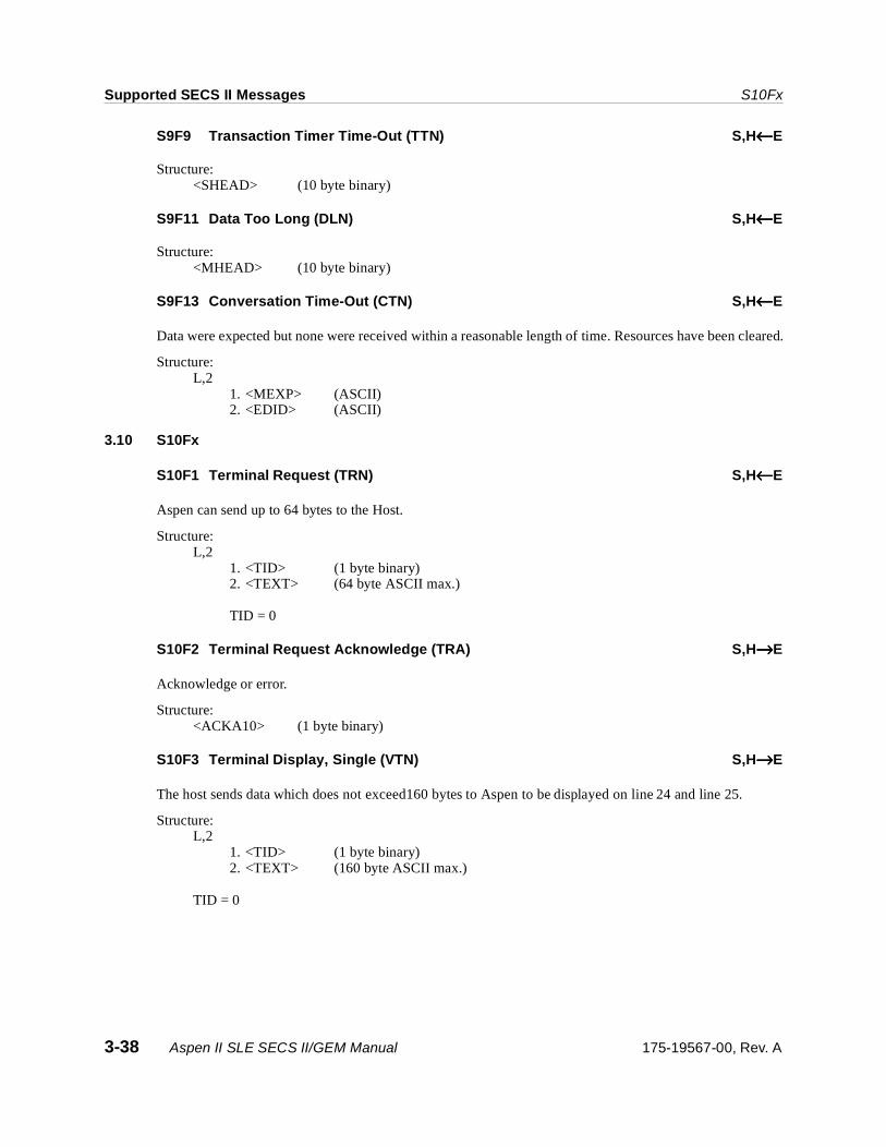
Supported SECS II Messages S10Fx
S9F9 Transaction Timer Time-Out (TTN) S,H←←←←E
Structure: <SHEAD> (10 byte binary)
S9F11 Data Too Long (DLN) S,H←←←←E
Structure: <MHEAD> (10 byte binary)
S9F13 Conversation Time-Out (CTN) S,H←←←←E
Data were expected but none were received within a reasonable length of time. Resources have been cleared.
Structure: L,2
1. <MEXP> (ASCII) 2. <EDID> (ASCII)
3.10 S10Fx
S10F1 Terminal Request (TRN) S,H←←←←E
Aspen can send up to 64 bytes to the Host.
Structure:L,2
1. <TID> (1 byte binary) 2. <TEXT> (64 byte ASCII max.)
TID = 0
S10F2 Terminal Request Acknowledge (TRA) S,H→→→→E
Acknowledge or error.
Structure:<ACKA10> (1 byte binary)
S10F3 Terminal Display, Single (VTN) S,H→→→→E
The host sends data which does not exceed160 bytes to Aspen to be displayed on line 24 and line 25.
Structure: L,2
1. <TID> (1 byte binary) 2. <TEXT> (160 byte ASCII max.)
TID = 0
3-38 Aspen II SLE SECS II/GEM Manual 175-19567-00, Rev. A
S10Fx Supported SECS II Messages
S10F4 Terminal Display, Single Acknowledge (VTA) S,H←←←←E
Acknowledge or error.
Structure: <ACKA10> (1 byte binary)
0 = Accepted for display.1 = Message will not be displayed.
S10F5 Terminal Display, Multi-Block (VTN) S,H→→→→E
The host sends data to Aspen to be displayed on a full screen page.
Structure: L,2
1. <TID> (1 byte binary) 2. L, n (n = 1 to 19)
1. <TEXT> (80 byte ASCII max.) ::n. <TEXT> (80 byte ASCII max.)
S10F6 Terminal Display, Multi-Block Acknowledge (VMA) S,H←←←←E
Acknowledge or error.
Structure: <ACKA10> (1 byte binary)
0 = Accepted for display.1 = Message will not be displayed.
175-19567-00, Rev. A Aspen II SLE SECS II/GEM Manual 3-39
Supported SECS II Messages S10Fx
3-40 Aspen II SLE SECS II/GEM Manual 175-19567-00, Rev. A

4.0 State Diagrams and Transition Tables
4.1 Communication State
Figure 4-1. Communications State Diagram
175-19567-00, Rev. A Aspen Strip SECS II/GEM Manual 4-1

State Diagrams and Transition Tables Communication State
Table 4-1: Communications State Transition Table
# Current State Trigger New State Action Comments
1 (Entry to COMMUNICATIONS)
System Initialization System Default None. The system default may be set to DISABLED or ENABLED.
2 (Entry to ENABLED) Any entry to ENABLED state
NOT COMMUNICATING
None. May enter from system initialization to ENABLED or through operator switch to ENABLED.
3 (Entry to EQUIPMENT-INITIATED CONNECT)
Any entry to NOT COMMUNICATING
WAIT CRA Initialize communications. Set CommDelay timer “Expired”. Send S1F13.
Begin the attempt to establish communications.
4 WAIT CRA Connection Transaction Failure
WAIT DELAY Initialize CommDelay timer. Dequeue all messages queued to send.
If appropriate, dequeued messages shall be placed in spool buffer in the order generated. Wait for timer to expire.
5 WAIT DELAY CommDelay timer expired
WAIT CRA Discard message. No reply. Set CommDelay timer “Expired”. Send S1F13.
Wait for S1F14. May receive S1F13 from Host.
6 WAIT DELAY Received a message other than S1F13.
WAIT CRA Discard message. No reply. Set CommDelay timer “Expired”. Send S1F13.
Indicates opportunity to establish communications.
7 WAIT CRA Received expected S1F14 with COMMACK = 0.
COMMUNICATING None. Communications Established.
8 (Entry to HOST-INITIATED CONNECT)
(Any entry to NOT COMMUNICAT-ING)
WAIT CR FROM HOST
None. Wait for S1F13 from Host.
9 WAIT CR FROM HOST
Received S1F13. WAIT TX COMPLETE
Send S1F14 with COMMACK = 0.
Host seeks to establish communications.
10 WAIT TX COMPLETE S1F14 transmission failed.
WAIT CR FROM HOST
None. Communications are established.
11 WAIT TX COMPLETE S1F14 transmission completed successfully.
COMMUNICATING None. Communications are established.
12 COMMUNICATING Communication failure.
NOT COMMUNICATING
Dequeue all messages queued to send.
Dequeued messages may be placed in spool buffer as appropriate.
4-2 Aspen Strip SECS II/GEM Manual 175-19567-00, Rev. A

Control State State Diagrams and Transition Tables
4.2 Control State
Figure 4-2. Control State Diagram
Table 4-2: Control State Transition Table
# Current State Trigger New State Action Comments
1 (Undefined) Entry into CONTROL state (system initialization).
CONTROL (Substate conditional on configuration).
None. Equipment may be configured to default to ON-LINE or OFF-Line.*
2 (Undefined) Entry into OFF-LINE state.
OFF-LINE (Substate conditional on configuration).
None. Equipment may be configured to default to any substate of OFF-LINE.
3 EQUIPMENT OFF-LINE
Operator actuates ON-LINE switch.
Attempt ON-LINE. None. Note that an S1F1 is sent whenever ATTEMPT ON-LINE is activated.
175-19567-00, Rev. A Aspen Strip SECS II/GEM Manual 4-3
State Diagrams and Transition Tables Control State
* The configuration mentioned for transitions 1 and 2 should be a single setting. This would provide the user with a choice of entering EQUIPMENT OFF-LINE, ATTEMPT ON-LINE, HOST OFF-LINE, or ON-LINE states.
** If SECS-I is used, this means the retry limit RTY is exceeded during the attempt to send a message.
*** Any host-initiated transaction open at the equipment must be completed. This may happen either by sending the appropriate reply to the host prior to sending the event message or by sending an SxF0 message following the event message (i.e. after the transaction).
4 Attempt ON-LINE S1F0 New state conditional upon configuration.
None. This may be due to a communication failure, ** reply timeout, or receipt of S1F0. Configuration may be set to EQUIPMENT OFF-LINE or HOST OFF-LINE.
5 Attempt ON-LINE Equipment receives expected S1F2 message from the host.
ON-LINE None. Host is notified of transition to ON-LINE at transition 7.
6 ON-LINE Operator actuates OFF-LINE switch.
EQUIPMENT OFF-LINE
None. “Equipment OFF-LINE” event occurs***. Event reply will be discarded while OFF-LINE is active.
7 (Undefined) Entry to ON-LINE state.
ON-LINE (Substate conditional on REMOTE/LOCAL switch setting.)
None. “Control State Local” or “Control State REMOTE” event occurs. Event reported based upon actual ON-LINE substate activated.
8 OPERATOR Operator sets control mode to SEMI-AUTO.
SEMI-AUTO None. “Control State SEMI-AUTO” event occurs.
9 SEMI-AUTO Operator sets control mode to OPERATOR.
OPERATOR None. “Control State OPERATOR” event occurs.
10 OPERATOR Operator sets control mode to ENGINEER.
ENGINEER None. “Control State ENGINEER” event occurs.
11 ENGINEER Operator sets control mode to OPERATOR.
OPERATOR None. “Control State OPERATOR” event occurs.
12 ENGINEER Operator sets control mode to SEMI-AUTO.
SEMI-AUTO None. “Control State SEMI-AUTO” event occurs.
13 SEMI-AUTO Operator sets control mode to ENGINEER.
ENGINEER None. “Control State ENGINEER” event occurs.
14 ON-LINE Equipment accepts “Set OFF-LINE” message from host (S1F15).
HOST OFF-LINE None. “Control State OFF-LINE” event occurs.
15 HOST OFF-LINE Equipment accepts host request to go ON-LINE (S1F17).
ON-LINE None. Host is notified to transition to ON-LINE at transition 7.
16 HOST OFF-LINE Operator actuates OFF-LINE switch.
EQUIPMENT OFF-LINE
None. Equipment “OFF_LINE” event occurs.
# Current State Trigger New State Action Comments
4-4 Aspen Strip SECS II/GEM Manual 175-19567-00, Rev. A
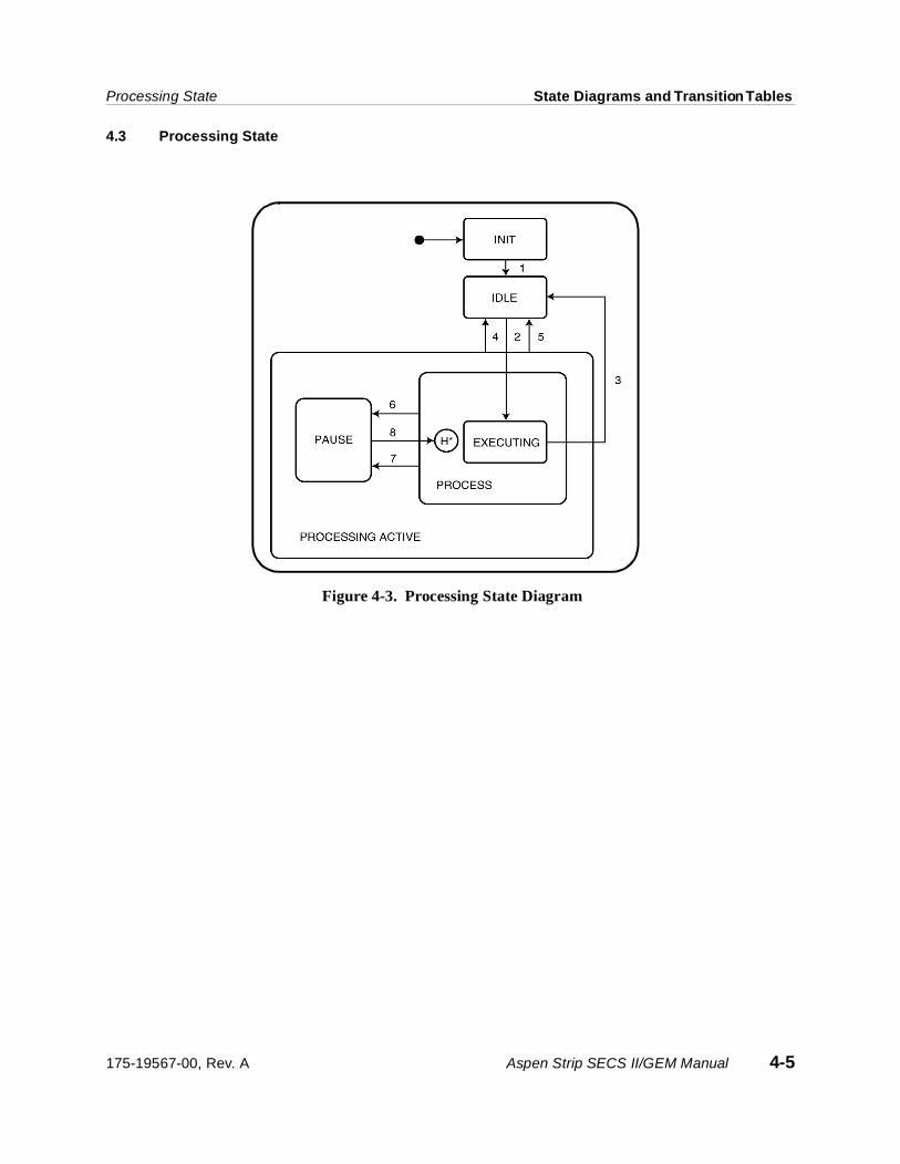
Processing State State Diagrams and Transition Tables
4.3 Processing State
Figure 4-3. Processing State Diagram
175-19567-00, Rev. A Aspen Strip SECS II/GEM Manual 4-5
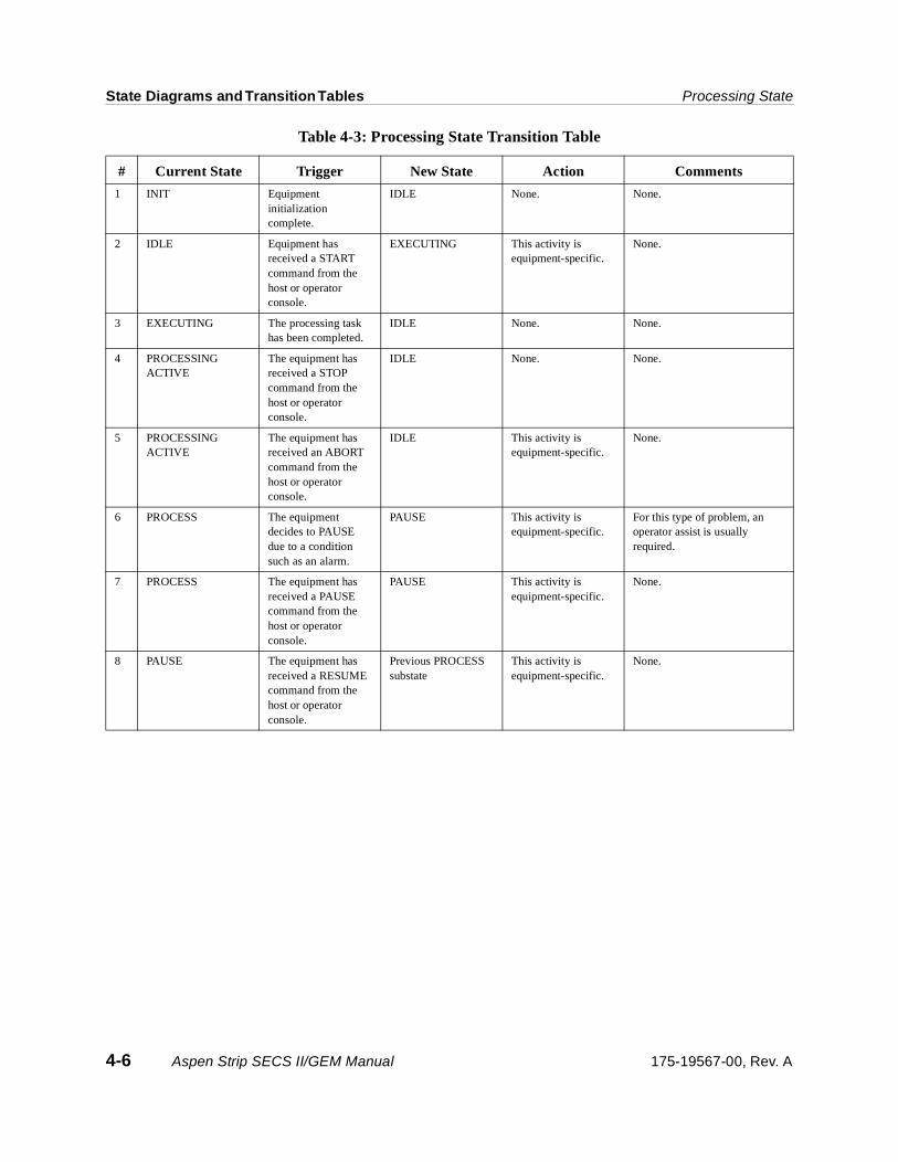
State Diagrams and Transition Tables Processing State
Table 4-3: Processing State Transition Table
# Current State Trigger New State Action Comments
1 INIT Equipment initialization complete.
IDLE None. None.
2 IDLE Equipment has received a START command from the host or operator console.
EXECUTING This activity is equipment-specific.
None.
3 EXECUTING The processing task has been completed.
IDLE None. None.
4 PROCESSING ACTIVE
The equipment has received a STOP command from the host or operator console.
IDLE None. None.
5 PROCESSING ACTIVE
The equipment has received an ABORT command from the host or operator console.
IDLE This activity is equipment-specific.
None.
6 PROCESS The equipment decides to PAUSE due to a condition such as an alarm.
PAUSE This activity is equipment-specific.
For this type of problem, an operator assist is usually required.
7 PROCESS The equipment has received a PAUSE command from the host or operator console.
PAUSE This activity is equipment-specific.
None.
8 PAUSE The equipment has received a RESUME command from the host or operator console.
Previous PROCESS substate
This activity is equipment-specific.
None.
4-6 Aspen Strip SECS II/GEM Manual 175-19567-00, Rev. A

Limit State State Diagrams and Transition Tables
4.4 Limit State
Figure 4-4. Limit State Diagram
Table 4-4: Limit State Transition Table
# Current State Trigger New State Action Comments
1 DISABLED Limit attributes defined with S2F45.
ENABLED None. The substate of ENABLED is determined by the current value of the monitored variable.
2 ENABLED Limit attributes set to undefined with S2F45.
DISABLED None. None.
3 BELOW LIMIT Variable increases to be ≥ UPPERDB.
ABOVE LIMIT None. Zone Transition.
4 ABOVE LIMIT Variable decreases to be ≤ LOWERDB.
BELOW LIMIT None. Zone Transition.
5 NO ZONE Variable decreases to be ≤ LOWERDB.
BELOW LIMIT None. Zone Transition.
6 NO ZONE Variable increases to be ≥ LOWERDB.
ABOVE LIMIT None. Zone Transition.
175-19567-00, Rev. A Aspen Strip SECS II/GEM Manual 4-7

State Diagrams and Transition Tables Alarm State
4.5 Alarm State
Figure 4-5. Alarm State Diagram
Table 4-5: Alarm State Transition Table
# Current State Trigger New State Action Comments
1 ALARMn CLEAR Alarmn is detected on the equipment.
ALARMn SET Initiate local actions (if any) to ensure safety. Update “AlarmSet” and ALCDn” values. Generate and issue alarm message, if enabled.
Inhibited activities require operator or host intervention prior to resuming.
2 ALARMn SET Alarmn is no longer detected on the equipment.
ALARMn CLEAR Update “AlarmSet” and “ALCDn” values. Generate and issue alarm message, if enabled.
Inhibited activities require operator or host intervention prior to resuming.
4-8 Aspen Strip SECS II/GEM Manual 175-19567-00, Rev. A

Appendix A—Alarm IDs
Alarm ID No. Message Description ALCD
1 MACHINE NOT SAFE Equipment Safety Error. I/O Electrical control function is in question.
82
2 ROBOT FAILED Unrecoverable Error. The robot was unable to complete a motion that it was commanded to execute.
85
3 CHAMBER PRESSURE FAILED Unrecoverable Error. The reactor chamber pressure was unable to reach its assigned pressure.
85
4 SHUTTLE PRESSURE SYSTEM FAILED
Unrecoverable Error. Shuttle pressure system was not able to complete its requested pressure change.
85
5 SHUTTLE FAILED Unrecoverable Error. The shuttle was unable to complete a motion that it was commanded to perform.
85
6 RF FAILED Parameter Control Error.RF output is outside of process limits.
84
7 GAS HANDLING ERROR Parameter Control Error. Process Gas control system was not properly used.
84
8 <gas name>: GAS 1 FAILED Parameter Control Error. Process Gas failed to work properly.
84
9 <gas name>: GAS 2 FAILED Parameter Control Error. Process Gas failed to work properly.
84
10 <gas name>: GAS 3 FAILED Parameter Control Error. Process Gas failed to work properly.
84
11 LEFT CASSETTE UNLOAD ERROR Unrecoverable Error. AGV/SMIF left cassette unload fails during transfer.
85
12 RIGHT CASSETTE UNLOAD ERROR
Unrecoverable Error. AGV/SMIF right cassette unload fails during transfer.
85
13 LEFT CASSETTE LOAD ERROR Unrecoverable Error. AGV/SMIF left cassette load fails during transfer.
85
14 RIGHT CASSETTE LOAD ERROR Unrecoverable Error. AGV/SMIF right cassette load fails during transfer.
85
15 PIO SIGNAL ERROR Unrecoverable Error. AGV PIO signal error during cassette transfer.
85
16 <gas name>: GAS 4 FAILED Parameter Control Error. Process Gas failed to work properly.
84
17 <gas name>: GAS 5 FAILED Parameter Control Error. Process Gas failed to work properly.
84
18 <gas name>: GAS 6 FAILED Parameter Control Error. Process Gas failed to work properly.
84
175-19567-00, Rev. A Aspen II SLE SECS II/GEM Manual A-1

Appendix A—Alarm IDs
19 <gas name>: GAS 7 FAILED Parameter Control Error. Process Gas failed to work properly.
84
20 <gas name>: GAS 8 FAILED Parameter Control Error. Process Gas failed to work properly.
84
Alarm ID No. Message Description ALCD
A-2 Aspen II SLE SECS II/GEM Manual 175-19567-00, Rev. A

Appendix B—Equipment Constants
ECID Description Units Format Min. Max. Default
0 Establish communication timeout. This value sets the time which Aspen will wait before re-attempting to check if the host is back online.
sec. 2 byte unsigned
1 3000 60
1 Sets the event reporting to be either annotated or not. If set to false, annotation will be excluded. If set to true, annotation will be included with the event reporting.
1 byte boolean
0 1 1
2 S4F9: T1 stuck in sender timeout.
Note: The default value for T1 is taken from the recommended default value in the SEMI specification manual.
sec. 2 byte unsigned
1 3000 10
3 S4F11: T2 stuck in receiver timeout.
Note: The default value for T2 is taken from the recommended default value in the SEMI specification manual.
sec. 2 byte unsigned
1 3000 60
4 S4F13: T3 send incomplete timeout.
Note: The default value for T3 is taken from the recommended default value in the SEMI specification manual.
sec. 2 byte unsigned
1 3000 70
5 Enable or disable static event reports. A two-byte unsigned integer is used to set 16 events. The LSB is for event 1 and the MSB is for event 16. A value of zero will disable all 16 events. See Appendix C for event listing.
2 byte unsigned
0000 FFFF 0000
6 Same as Equipment Constant ID 5 except for the event number. A two-byte unsigned integer is assigned for event 17 to event 32.
2 byte unsigned
0000 FFFF 0000
7 Sets the Establish Communication message to be either S1F1 or S1F13. If set to false (default), then the S1F1 message will be used. If set to true, then the S1F13 message will be used.
1 byte boolean
0 1 0
8 Sets the Spool Overwrite flag. If set to true, then the message spool will overwrite the oldest message when the spooled message area becomes full. If set to false, then the new messages will be dropped.
1 byte boolean
0 1 0
9 Sets the Max. Spool Transmit message value. The minimum value is 0 messages and the max. (default) value is 250 messages. This value is used with the S2F43 spooling command.
# msgs 2 byte unsigned
0 250 250
10 GEM Equipment Flag. 1 byte boolean
0 1 0
11 Same as Equipment Constant ID 5 except for the event number. A two-byte unsigned integer is assigned for event 33 to event 48.
2 byte unsigned
0000 FFFF 0000
175-19567-00, Rev. A Aspen II SLE SECS II/GEM Manual B-1

Appendix B—Equipment Constants
12 Same as Equipment Constant ID 5 except for the event number. A two-byte unsigned integer is assigned for event 49 to event 64.
2 byte unsigned
0000 FFFF 0000
13 Sets Four-Digit Year Flag. Year 2000 compliance with 16 digit date and time format. If flag is set, 16-digit format; otherwise, 12-digit format.
1 byte boolean
0 1 0
14 Auto Query S3F11. Aspen will send S3F11 if MID is not assigned in remote mode.
1 byte boolean
0 1 0
15 Spooling Enabled / Disabled. If set to true, then message spooling is enabled. If set to false, then message spooling is disabled.
1 byte boolean
0 1 0
ECID Description Units Format Min. Max. Default
B-2 Aspen II SLE SECS II/GEM Manual 175-19567-00, Rev. A

Appendix C—Event IDs
<CEID> Message Event Description
1 Setup Started. Start of swap cassettes. The Aspen system has started to set up for processing a batch of wafers contained in the cassettes which were positioned onto the shuttle.
2 Setup Completed. Swap cassettes and pin search completed. The shuttle has completed its rotation and is in place for processing the wafers. The robot has completed its pin search calibration function.
3 Process Started. Batch processing started. Processing of a complete batch of wafers has started. This event occurs as soon as the robot starts placing wafers into the process chamber.
4 RF On. Beginning of an RF cycle.
5 RF Off. RF cycle has completed.
6 Process Completed. Batch processing completed. The processing of a complete batch of wafers has completed. The robot is idle and the shuttle is available for rotation.
7 Paused. System held. The Aspen system has been placed in holding mode.
8 Resumed. System un-held. The Aspen system has been taken out of the holding mode.
9 Aborted. Reset. Reset command has been entered by means of the keyboard or operator button.
10 Alarm Paused. Equipment Error Handler. Equipment is hard down. The Aspen equipment is unable to continue its operation and requires personnel attention.
11 Alarm Cleared. Replied to Error Handler. The alarm pause has been cleared by personnel by way of the keyboard.
12 Left Cassette Removed. The left cassette has been removed from the outer cassette nests.
13 Left Cassette Inserted. The left cassette has been inserted in the outer cassette nests.
14 Process Step Started. Indicates the start of a processing step.
15 Process Step Ended. Indicates the termination of a processing step.
16 Wafer Process Started. Start of a wafer process cycle.
17 Wafer Process Ended. Completion of a wafer process cycle.
18 Cassette Door Up. The cassette door is in the open position.
19 Cassette Door Down. The cassette door is in the closed position.
20 Unload Material Request. Aspen is presenting finished cassettes for unload.
21 Unloading Material Completed. Finished cassettes have been removed.
22 Load Material Request. Aspen is requesting that material be loaded.
23 Loading Material Completed. One or two cassettes have been loaded.
175-19567-00, Rev. A Aspen II SLE SECS II/GEM Manual C-1

Appendix C—Event IDs
24 RF Power Zone Transition.
25 Chamber Pressure Zone Transition.
26 Gas 1 Flow Zone Transition.
27 Gas 2 Flow Zone Transition.
28 Gas 3 Flow Zone Transition.
29 Chamber Temperature Zone Transition.
30 Spooling Deactivated.
31 End Point Completed.
32 Step Sampling Data Reporting. Need to set SII field of recipe step to 'Y' for this event. The event will occur at half of the elapsed RF time if the step is not an end point step. For an end point step, the event will occur after end point has completed.
33 Top Wafer Number Request in Remote Mode.
34 Bottom Wafer Number Request in Remote Mode.
35 Recipe Selection Request in Remote Mode.
36 Right Cassette Removed. The right cassette has been removed from the outer cassette nests.
37 Right Cassette Inserted. The right cassette has been inserted in the outer cassette nests.
38 Run Request in Remote Mode.
39 Prompt to Open Cassette Door.
40 Equipment Mode Changed. Equipment mode switched between Operator/Remote Mode and Engineering Mode.
41 Ready to Return Cassettes. Inner cassettes were completed with no outer cassettes loaded. Send the event every five minutes.
42 Idle Notification. Aspen idle timeout notification.
43 Process Chamber Enabled/Disabled. Chamber has switched between enabled and disabled.
44 Operator Changed ON-LINE to OFF-LINE.
45 Prompt to Close Cassette Door.
46 Leak Test Completed.
47 Error or Warning Message.
48 Route Request in Remote Mode. Tool requests route to run. (SLE Software Only)
*49 End Point Completed. (Second chamber)
*50 Step Sampling Data Reporting. (Second chamber)
*51 RF On. (Second chamber) Beginning of an RF cycle.
*52 RF Off. (Second chamber) RF cycle has completed.
*53 Process Step Started. (Second chamber) Indicates the start of a processing step.
*54 Process Step Completed. (Second chamber) Indicates the termination of a processing step.
<CEID> Message Event Description
C-2 Aspen II SLE SECS II/GEM Manual 175-19567-00, Rev. A

Appendix C—Event IDs
*55 Wafer Process Started. (Second chamber) Start of a wafer process cycle.
*56 Wafer Process Completed. (Second chamber) Completion of a wafer process cycle.
*57 RF Power Zone Transition. (Second chamber)
*58 Chamber Pressure Zone Transition. (Second chamber)
*59 Gas 1 Flow Zone Transition. (Second chamber)
*60 Gas 2 Flow Zone Transition. (Second chamber)
*61 Gas 3 Flow Zone Transition. (Second chamber)
*62 Chamber Temperature Zone Transition (Second chamber)
*63 Process Chamber Enabled/Disabled. (Second chamber)
Chamber switched between enabled and disabled.
64 Reserved.
65 Reserved. Special feature for Hyundai in SLE software.
66 Wafer Count Error.
67 Request to Verify Single Cassette in Operator Choice Mode.
68 Request for Left Wafer Number.
69 Request for Right Wafer Number.
70 Left Pod in Place. (Fortrend PIO)
71 Right Pod in Place. (Fortrend PIO)
72 Load Left Cassette Request. (Fortrend PIO)
73 Load Right Cassette Request. (Fortrend PIO)
74 Load Left Cassette Completed. (Fortrend PIO)
75 Load Right Cassette Completed. (Fortrend PIO)
76 Unload Left Cassette Request. (Fortrend PIO)
77 Unload Right Cassette Request. (Fortrend PIO)
78 Unload Left Cassette Completed. (Fortrend PIO)
79 Unload Right Cassette Completed. (Fortrend PIO)
80 Ready to Remove Left Pod. (Fortrend PIO)
81 Ready to Remove Right Pod. (Fortrend PIO)
82 Left Pod Removed. (Fortrend PIO)
83 Right Pod Removed. (Fortrend PIO)
84 Left PIO Communication Error. (Fortrend PIO)
85 Right PIO Communication Error. (Fortrend PIO)
86 Wafer Mapping Completed.
87 Cassette Shuttle Up.
<CEID> Message Event Description
175-19567-00, Rev. A Aspen II SLE SECS II/GEM Manual C-3
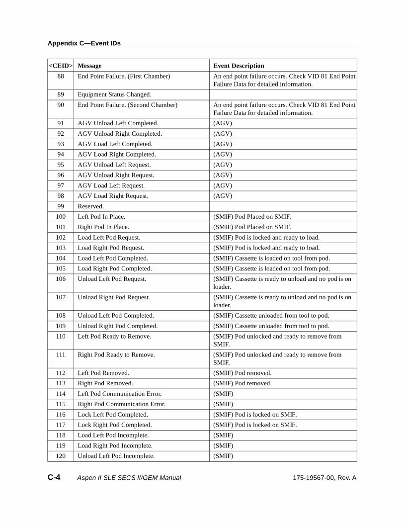
Appendix C—Event IDs
88 End Point Failure. (First Chamber) An end point failure occurs. Check VID 81 End Point Failure Data for detailed information.
89 Equipment Status Changed.
90 End Point Failure. (Second Chamber) An end point failure occurs. Check VID 81 End Point Failure Data for detailed information.
91 AGV Unload Left Completed. (AGV)
92 AGV Unload Right Completed. (AGV)
93 AGV Load Left Completed. (AGV)
94 AGV Load Right Completed. (AGV)
95 AGV Unload Left Request. (AGV)
96 AGV Unload Right Request. (AGV)
97 AGV Load Left Request. (AGV)
98 AGV Load Right Request. (AGV)
99 Reserved.
100 Left Pod In Place. (SMIF) Pod Placed on SMIF.
101 Right Pod In Place. (SMIF) Pod Placed on SMIF.
102 Load Left Pod Request. (SMIF) Pod is locked and ready to load.
103 Load Right Pod Request. (SMIF) Pod is locked and ready to load.
104 Load Left Pod Completed. (SMIF) Cassette is loaded on tool from pod.
105 Load Right Pod Completed. (SMIF) Cassette is loaded on tool from pod.
106 Unload Left Pod Request. (SMIF) Cassette is ready to unload and no pod is on loader.
107 Unload Right Pod Request. (SMIF) Cassette is ready to unload and no pod is on loader.
108 Unload Left Pod Completed. (SMIF) Cassette unloaded from tool to pod.
109 Unload Right Pod Completed. (SMIF) Cassette unloaded from tool to pod.
110 Left Pod Ready to Remove. (SMIF) Pod unlocked and ready to remove from SMIF.
111 Right Pod Ready to Remove. (SMIF) Pod unlocked and ready to remove from SMIF.
112 Left Pod Removed. (SMIF) Pod removed.
113 Right Pod Removed. (SMIF) Pod removed.
114 Left Pod Communication Error. (SMIF)
115 Right Pod Communication Error. (SMIF)
116 Lock Left Pod Completed. (SMIF) Pod is locked on SMIF.
117 Lock Right Pod Completed. (SMIF) Pod is locked on SMIF.
118 Load Left Pod Incomplete. (SMIF)
119 Load Right Pod Incomplete. (SMIF)
120 Unload Left Pod Incomplete. (SMIF)
<CEID> Message Event Description
C-4 Aspen II SLE SECS II/GEM Manual 175-19567-00, Rev. A

Appendix C—Event IDs
* The second chamber's Event IDs are only valid in a dual-chamber system. If a system is configured with only one chamber, no matter on which side the chamber is mounted, the second chamber's Event IDs will be invalid. The Aspen system always uses the first set of Event IDs for single-chamber systems.
For dual-chamber systems, the first chamber is assigned to the RIGHT chamber and the second chamber is assigned to the BACK chamber.
121 Unload Right Pod Incomplete. (SMIF)
122 Reserved.
123 Reserved.
124 Reserved.
125 Reserved.
126 Reserved.
127 Reserved.
128 Reserved.
129 Reserved.
130 Reserved.
131 Reserved.
132 Preconditioning Start.
133 Preconditioning Complete.
*134 Preconditioning Start. (Second Chamber)
*135 Preconditioning Complete. (Second Chamber)
136 Wafer Cycle Start.
137 Wafer Cycle Complete.
138 Recipe Modified.
139 Recipe Route Modified.
140 Gas 4 Zone Transition.
141 Gas 5 Zone Transition.
142 Gas 6 Zone Transition.
143 Gas 7 Zone Transition.
144 Gas 8 Zone Transition.
*145 Gas 4 Zone Transition. (Second chamber)
*146 Gas 5 Zone Transition. (Second chamber)
*147 Gas 6 Zone Transition. (Second chamber)
*148 Gas 7 Zone Transition. (Second chamber)
*149 Gas 8 Zone Transition. (Second chamber)
150 Low Power Zone Transition.
151 Second Low Power Zone Transition.
152 Wafer Mapping Data Request.
<CEID> Message Event Description
175-19567-00, Rev. A Aspen II SLE SECS II/GEM Manual C-5
Appendix C—Event IDs
C-6 Aspen II SLE SECS II/GEM Manual 175-19567-00, Rev. A

Appendix D—Variable IDs
The limit value of the items marked with * in the Limit column can be defined by S2F87.
The available Aspen Variable IDs <VID> and associated data is as follows:
<VID> Data Description Units Format Limit
0 Date and Time
yymmddhhmmss if ECID 13 is set to 0.yyyymmddhhmmsscc if ECID 13 is set to 1.
12 or 16 byte ASCII
1 Processing Recipe Name (First Chamber) 25 byte ASCII
2 Processing Recipe Step Number (First Chamber) 2 byte integer
3 RF Power Setting (First Chamber) Watts 2 byte integer
4 Process Pressure Setting (First Chamber) Torr 4 byte floating
5 RF Time Setting (First Chamber) sec 4 byte floating
6 Gas 1 Flow Setting (First Chamber) sccm 2 byte unsigned
7 Gas 2 Flow Setting (First Chamber) sccm 2 byte unsigned
8 Gas 3 Flow Setting (First Chamber) sccm 2 byte unsigned
9 Process Delay Time (First Chamber) sec 4 byte floating
10 Temperature Setting (First Chamber) °C 2 byte integer
11 RF Forward Power Actual (First Chamber) Watts 2 byte integer *
12 RF Elapsed Time Actual (First Chamber) sec 4 byte floating
13 Process Pressure Actual (First Chamber) Torr 4 byte floating *
14 Gas 1 Flow Actual (First Chamber) sccm 2 byte unsigned *
15 Gas 2 Flow Actual (First Chamber) sccm 2 byte unsigned *
16 Gas 3 Flow Actual (First Chamber) sccm 2 byte unsigned *
17 Temperature Actual (First Chamber) °C 2 byte integer *
18 Left Wafer Number in Chamber (First Chamber) 2 byte unsigned
19 Loadlock Pressure Torr 4 byte floating
20 Shuttle Pressure Torr 4 byte floating
21 Left Outer Material ID 16 byte ASCII
22 Right Outer Material ID 16 byte ASCII
23 Left Inner Material ID 16 byte ASCII
24 Right Inner Material ID 16 byte ASCII
25 Aspen Equipment Mode 0 = Engineering Mode1 = Operator Mode2 = Remote Mode (Semi-Auto Mode)3 = Auto Mode (AGV Mode)
1 byte binary
175-19567-00, Rev. A Aspen II SLE SECS II/GEM Manual D-1

Appendix D—Variable IDs
26 Aspen Equipment Status0 = Idle1 = Processing2 = Paused3 = Down
1 byte binary
27 Left Outer Cassette Nest Status 0 = No Cassette1 = Unfinished Cassette2 = Finished Cassette
1 byte binary
28 Left Inner Cassette Nest Status 0 = No Cassette 1 = Unfinished Cassette2 = Finished Cassette
1 byte binary
29 Cassette Door Status0 = Door Up1 = Door Down2 = Door Between Up and Down Position
1 byte binary
30 RF Reverse Power Actual (First Chamber) Watts 2 byte integer
31 End Point Time (First Chamber) sec 4 byte floating
32 Right Wafer Number in Chamber (First Chamber) 2 byte unsigned
33 Right Outer Cassette Nest Status0 = No Cassette1 = Unfinished Cassette2 = Finished Cassette
1 byte binary
34 Right Inner Cassette Nest Status0 = No Cassette1 = Unfinished Cassette2 = Finished Cassette
1 byte binary
35 Left Wafer Number on Top Plate Of Cooldown Chamber 2 byte unsigned
36 Right Wafer Number on Bottom Plate of Cooldown Chamber
2 byte unsigned
37 Left Wafer Number on Top Plate of Cooldown Chamber 2 byte unsigned
38 Right Wafer Number on Bottom Plate of Cooldown Chamber
2 byte unsigned
<VID> Data Description Units Format Limit
D-2 Aspen II SLE SECS II/GEM Manual 175-19567-00, Rev. A

Appendix D—Variable IDs
39 Equipment Remote Status0 = Not Ready to Load, Unload, or Run Outer
Cassettes1 = Ready to Open Cassette Door with Outer
Cassettes Present2 = Ready to Open Cassette Door Without Outer
Cassettes Present3 = Ready to Unload Outer Cassettes4 = Ready to Load Outer Cassettes5 = Ready to Accept the Top Wafer Number6 = Ready to Accept the Bottom Wafer Number7 = Ready to Accept the Recipe Number8 = Ready to Run the Outer Cassettes9 = Ready to have Wafer Map Accepted10 =Ready to Accept Left Wafer Count11 =Ready to Accept Right Wafer Count
2 byte integer
40 End Point Left CO2 Data (First Chamber) 2 byte integer
41 End Point Left O2 Data (First Chamber) 2 byte integer
42 End Point Right CO2 Data (First Chamber) 2 byte integer
43 End Point Right O2 Data (First Chamber) 2 byte integer
44 Process Chamber Status (First Chamber)0 = Disabled1 = Enabled
2 byte integer
45 Wafers of Inner Cassettes Processed 2 byte integer
46 Outer Cassettes Recipe Name (First Chamber) 25 byte ASCII
47 Inner Cassettes Recipe Number (First Chamber) 2 byte integer
48 Outer Cassettes Recipe Number (First Chamber) 2 byte integer
49 Chamber Location Process Chamber Variables0 = Back Chamber Installed 1 = Right Chamber Installed2 = Right and Back Chambers Installed
2 byte integer
*51 Processing Recipe Name (Second Chamber) 25 byte ASCII
*52 Processing Recipe Step Number (Second Chamber) 2 byte integer
*53 RF Power Setting (Second Chamber) Watts 2 byte integer
*54 Process Pressure Setting (Second Chamber) Torr 4 byte floating
*55 RF Time Setting (Second Chamber) sec 4 byte floating
*56 Gas 1 Flow Setting (Second Chamber) sccm 2 byte unsigned
*57 Gas 2 Flow Setting (Second Chamber) sccm 2 byte unsigned
*58 Gas 3 Flow Setting (Second Chamber) sccm 2 byte unsigned
*59 Process Delay Time (Second Chamber) sec 4 byte floating
*60 Temperature Setting (Second Chamber) °C 2 byte integer
<VID> Data Description Units Format Limit
175-19567-00, Rev. A Aspen II SLE SECS II/GEM Manual D-3
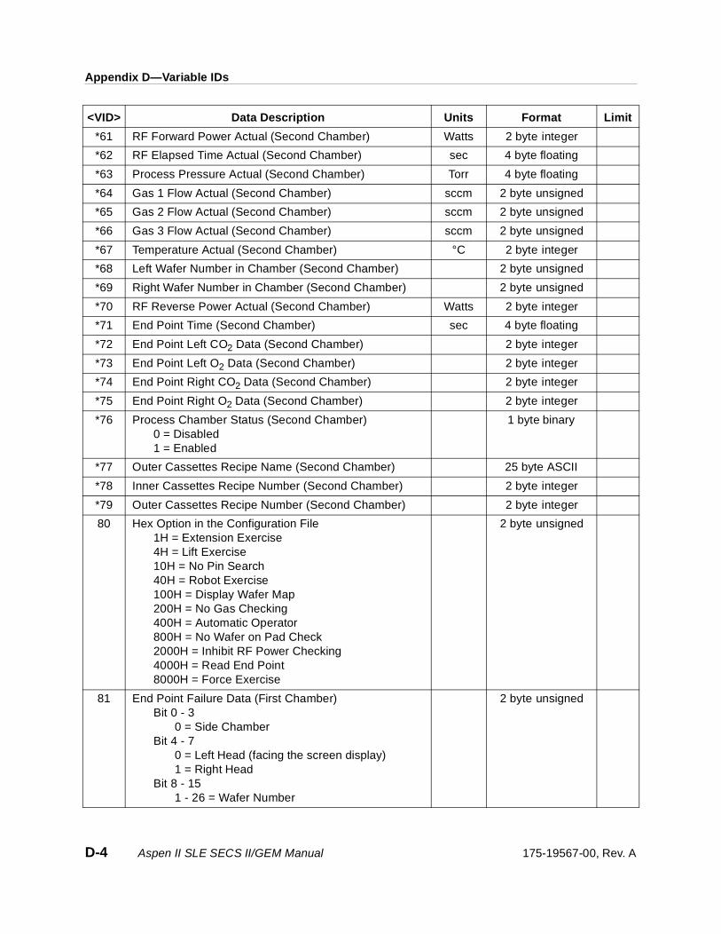
Appendix D—Variable IDs
*61 RF Forward Power Actual (Second Chamber) Watts 2 byte integer
*62 RF Elapsed Time Actual (Second Chamber) sec 4 byte floating
*63 Process Pressure Actual (Second Chamber) Torr 4 byte floating
*64 Gas 1 Flow Actual (Second Chamber) sccm 2 byte unsigned
*65 Gas 2 Flow Actual (Second Chamber) sccm 2 byte unsigned
*66 Gas 3 Flow Actual (Second Chamber) sccm 2 byte unsigned
*67 Temperature Actual (Second Chamber) °C 2 byte integer
*68 Left Wafer Number in Chamber (Second Chamber) 2 byte unsigned
*69 Right Wafer Number in Chamber (Second Chamber) 2 byte unsigned
*70 RF Reverse Power Actual (Second Chamber) Watts 2 byte integer
*71 End Point Time (Second Chamber) sec 4 byte floating
*72 End Point Left CO2 Data (Second Chamber) 2 byte integer
*73 End Point Left O2 Data (Second Chamber) 2 byte integer
*74 End Point Right CO2 Data (Second Chamber) 2 byte integer
*75 End Point Right O2 Data (Second Chamber) 2 byte integer
*76 Process Chamber Status (Second Chamber)0 = Disabled1 = Enabled
1 byte binary
*77 Outer Cassettes Recipe Name (Second Chamber) 25 byte ASCII
*78 Inner Cassettes Recipe Number (Second Chamber) 2 byte integer
*79 Outer Cassettes Recipe Number (Second Chamber) 2 byte integer
80 Hex Option in the Configuration File1H = Extension Exercise4H = Lift Exercise10H = No Pin Search40H = Robot Exercise100H = Display Wafer Map200H = No Gas Checking400H = Automatic Operator800H = No Wafer on Pad Check2000H = Inhibit RF Power Checking4000H = Read End Point8000H = Force Exercise
2 byte unsigned
81 End Point Failure Data (First Chamber)Bit 0 - 3
0 = Side ChamberBit 4 - 7
0 = Left Head (facing the screen display)1 = Right Head
Bit 8 - 151 - 26 = Wafer Number
2 byte unsigned
<VID> Data Description Units Format Limit
D-4 Aspen II SLE SECS II/GEM Manual 175-19567-00, Rev. A
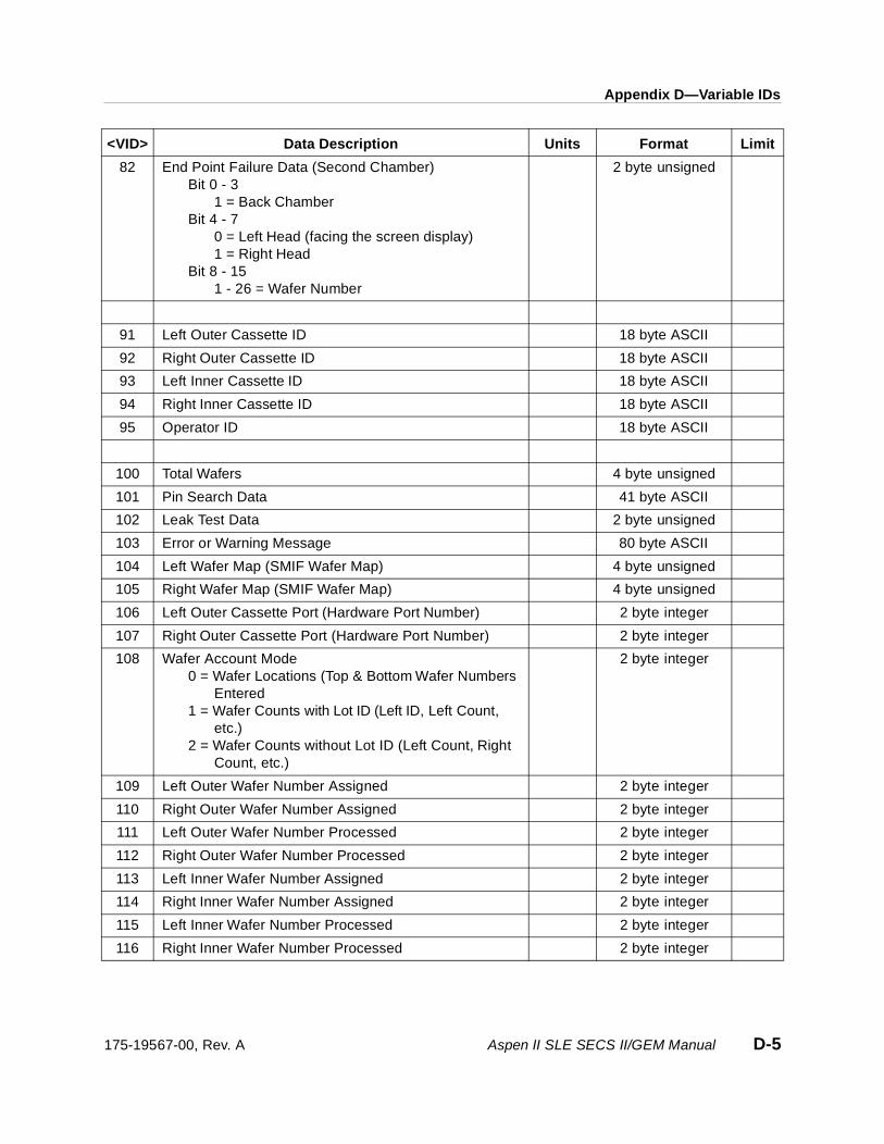
Appendix D—Variable IDs
82 End Point Failure Data (Second Chamber)Bit 0 - 3
1 = Back ChamberBit 4 - 7
0 = Left Head (facing the screen display)1 = Right Head
Bit 8 - 151 - 26 = Wafer Number
2 byte unsigned
91 Left Outer Cassette ID 18 byte ASCII
92 Right Outer Cassette ID 18 byte ASCII
93 Left Inner Cassette ID 18 byte ASCII
94 Right Inner Cassette ID 18 byte ASCII
95 Operator ID 18 byte ASCII
100 Total Wafers 4 byte unsigned
101 Pin Search Data 41 byte ASCII
102 Leak Test Data 2 byte unsigned
103 Error or Warning Message 80 byte ASCII
104 Left Wafer Map (SMIF Wafer Map) 4 byte unsigned
105 Right Wafer Map (SMIF Wafer Map) 4 byte unsigned
106 Left Outer Cassette Port (Hardware Port Number) 2 byte integer
107 Right Outer Cassette Port (Hardware Port Number) 2 byte integer
108 Wafer Account Mode0 = Wafer Locations (Top & Bottom Wafer Numbers
Entered1 = Wafer Counts with Lot ID (Left ID, Left Count,
etc.)2 = Wafer Counts without Lot ID (Left Count, Right
Count, etc.)
2 byte integer
109 Left Outer Wafer Number Assigned 2 byte integer
110 Right Outer Wafer Number Assigned 2 byte integer
111 Left Outer Wafer Number Processed 2 byte integer
112 Right Outer Wafer Number Processed 2 byte integer
113 Left Inner Wafer Number Assigned 2 byte integer
114 Right Inner Wafer Number Assigned 2 byte integer
115 Left Inner Wafer Number Processed 2 byte integer
116 Right Inner Wafer Number Processed 2 byte integer
<VID> Data Description Units Format Limit
175-19567-00, Rev. A Aspen II SLE SECS II/GEM Manual D-5

Appendix D—Variable IDs
117 Chamber Selected for Recipe Load(Returns 10 for Side Chamber; Returns 11 for Back Chamber)
2 byte integer
158 Inner Routing Recipe Number 2 byte integer
159 Outer Routing Recipe Number 2 byte integer
160 Inner Routing Selection0 = Right Chamber Only1 = Back Chamber Only2 = Parallel3 = Sequential, Right First4 = Sequential, Back First
2 byte integer
161 Outer Routing Selection0 = Right Chamber Only1 = Back Chamber Only2 = Parallel3 = Sequential, Right First4 = Sequential, Back First
2 byte integer
162 Process Mode (First Chamber)0 = Regular Process1 = Endpoint Calibration2 = Precondition Process
2 byte integer
163 Process Mode (Second Chamber)0 = Regular Process1 = Endpoint Calibration2 = Precondition Process
2 byte integer
164 Left Wafer Number Cycle Start/Complete 2 byte integer
165 Right Wafer Number Cycle Start/Complete 2 byte integer
166 Left Wafer Endpoint Time Independent Head (First Chamber)
4 byte floating
167 Right Wafer Endpoint Time Independent Head (First Chamber)
4 byte floating
168 Left Wafer Endpoint Time Independent Head (Second Chamber)
4 byte floating
169 Right Wafer Endpoint Time Independent Head (Second Chamber)
4 byte floating
170 Right Chamber RF Run Time (Hours) 4 byte integer
171 Second Right Chamber RF Run Time (Hours) 4 byte integer
172 Third Right Chamber RF Run Time (Hours) 4 byte integer
173 Fourth Right Chamber RF Run Time (Hours) 4 byte integer
174 Fifth Right Chamber RF Run Time (Hours) 4 byte integer
175 Back Chamber RF Run Time (Hours) 4 byte integer
<VID> Data Description Units Format Limit
D-6 Aspen II SLE SECS II/GEM Manual 175-19567-00, Rev. A
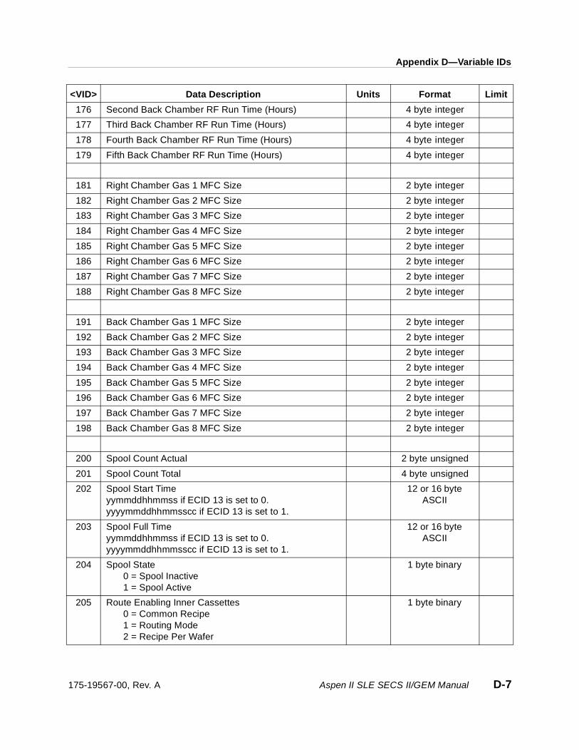
Appendix D—Variable IDs
176 Second Back Chamber RF Run Time (Hours) 4 byte integer
177 Third Back Chamber RF Run Time (Hours) 4 byte integer
178 Fourth Back Chamber RF Run Time (Hours) 4 byte integer
179 Fifth Back Chamber RF Run Time (Hours) 4 byte integer
181 Right Chamber Gas 1 MFC Size 2 byte integer
182 Right Chamber Gas 2 MFC Size 2 byte integer
183 Right Chamber Gas 3 MFC Size 2 byte integer
184 Right Chamber Gas 4 MFC Size 2 byte integer
185 Right Chamber Gas 5 MFC Size 2 byte integer
186 Right Chamber Gas 6 MFC Size 2 byte integer
187 Right Chamber Gas 7 MFC Size 2 byte integer
188 Right Chamber Gas 8 MFC Size 2 byte integer
191 Back Chamber Gas 1 MFC Size 2 byte integer
192 Back Chamber Gas 2 MFC Size 2 byte integer
193 Back Chamber Gas 3 MFC Size 2 byte integer
194 Back Chamber Gas 4 MFC Size 2 byte integer
195 Back Chamber Gas 5 MFC Size 2 byte integer
196 Back Chamber Gas 6 MFC Size 2 byte integer
197 Back Chamber Gas 7 MFC Size 2 byte integer
198 Back Chamber Gas 8 MFC Size 2 byte integer
200 Spool Count Actual 2 byte unsigned
201 Spool Count Total 4 byte unsigned
202 Spool Start Timeyymmddhhmmss if ECID 13 is set to 0.yyyymmddhhmmsscc if ECID 13 is set to 1.
12 or 16 byte ASCII
203 Spool Full Timeyymmddhhmmss if ECID 13 is set to 0.yyyymmddhhmmsscc if ECID 13 is set to 1.
12 or 16 byte ASCII
204 Spool State0 = Spool Inactive1 = Spool Active
1 byte binary
205 Route Enabling Inner Cassettes0 = Common Recipe1 = Routing Mode2 = Recipe Per Wafer
1 byte binary
<VID> Data Description Units Format Limit
175-19567-00, Rev. A Aspen II SLE SECS II/GEM Manual D-7

Appendix D—Variable IDs
206 Route Enabling Outer Cassettes0 = Common Recipe1 = Routing Mode2 = Recipe Per Wafer
1 byte binary
207 Current Active Chamber
0 = Side Chamber1 = Back Chamber
2 byte unsigned
211 Number of the Recipe Modified 2 byte unsigned
212 Name of the Recipe Modified 25 byte ASCII
213 Number of the Recipe Route Modified 2 byte unsigned
214 Name of the Recipe Route Modified 40 byte ASCII
215 Tool Total Maintenance Wafer Count 4 byte integer
216 Right Chamber Processed Wafer Count 4 byte integer
217 Second Right Chamber Processed Wafer Count 4 byte integer
218 Third Right Chamber Processed Wafer Count 4 byte integer
219 Fourth Right Chamber Processed Wafer Count 4 byte integer
220 Fifth Right Chamber Processed Wafer Count 4 byte integer
221 Back Chamber Processed Wafer Count 4 byte integer
222 Second Back Chamber Processed Wafer Count 4 byte integer
223 Third Back Chamber Processed Wafer Count 4 byte integer
224 Fourth Back Chamber Processed Wafer Count 4 byte integer
225 Fifth Back Chamber Processed Wafer Count 4 byte integer
226 Tool Total Maintenance Wafer Setpoint 4 byte integer
227 Right Chamber Wafer Setpoint 4 byte integer
228 Second Right Chamber Wafer Setpoint 4 byte integer
229 Third Right Chamber Wafer Setpoint 4 byte integer
230 Fourth Right Chamber Wafer Setpoint 4 byte integer
231 Fifth Right Chamber Wafer Setpoint 4 byte integer
232 Tool Total Maintenance Wafer Setpoint 4 byte integer
233 Back Chamber Wafer Setpoint 4 byte integer
234 Second Back Chamber Wafer Setpoint 4 byte integer
235 Third Back Chamber Wafer Setpoint 4 byte integer
236 Fourth Back Chamber Wafer Setpoint 4 byte integer
237 Fifth Back Chamber Wafer Setpoint 4 byte integer
238 Right Chamber RF Run Setpoint (Hours) 4 byte integer
239 Second Right Chamber RF Run Setpoint (Hours) 4 byte integer
240 Third Right Chamber RF Run Setpoint (Hours) 4 byte integer
<VID> Data Description Units Format Limit
D-8 Aspen II SLE SECS II/GEM Manual 175-19567-00, Rev. A

Appendix D—Variable IDs
241 Fourth Right Chamber RF Run Setpoint (Hours) 4 byte integer
242 Fifth Right Chamber RF Run Setpoint (Hours) 4 byte integer
243 Back Chamber RF Run Setpoint (Hours) 4 byte integer
244 Second Back Chamber RF Run Setpoint (Hours) 4 byte integer
245 Third Back Chamber RF Run Setpoint (Hours) 4 byte integer
246 Fourth Back Chamber RF Run Setpoint (Hours) 4 byte integer
247 Fifth Back Chamber RF Run Setpoint (Hours) 4 byte integer
301 Total RF Time (First Chamber) 4 byte floating
302 Gas 4 Flow Set (First Chamber) sccm 2 byte unsigned
303 Gas 5 Flow Set (First Chamber) sccm 2 byte unsigned
304 Gas 6 Flow Set (First Chamber) sccm 2 byte unsigned
305 Gas 7 Flow Set (First Chamber) sccm 2 byte unsigned
306 Gas 8 Flow Set (First Chamber) sccm 2 byte unsigned
307 Gas 4 Flow Actual (First Chamber) sccm 2 byte unsigned
308 Gas 5 Flow Actual (First Chamber) sccm 2 byte unsigned
309 Gas 6 Flow Actual (First Chamber) sccm 2 byte unsigned
310 Gas 7 Flow Actual (First Chamber) sccm 2 byte unsigned
311 Gas 8 Flow Actual (First Chamber) sccm 2 byte unsigned
*401 Total RF Time (Second Chamber) 4 byte floating
*402 Gas 4 Flow Set (Second Chamber) sccm 2 byte unsigned
*403 Gas 5 Flow Set (Second Chamber) sccm 2 byte unsigned
*404 Gas 6 Flow Set (Second Chamber) sccm 2 byte unsigned
*405 Gas 7 Flow Set (Second Chamber) sccm 2 byte unsigned
*406 Gas 8 Flow Set (Second Chamber) sccm 2 byte unsigned
*407 Gas 4 Flow Actual (Second Chamber) sccm 2 byte unsigned
*408 Gas 5 Flow Actual (Second Chamber) sccm 2 byte unsigned
*409 Gas 6 Flow Actual (Second Chamber) sccm 2 byte unsigned
*410 Gas 7 Flow Actual (Second Chamber) sccm 2 byte unsigned
*411 Gas 8 Flow Actual (Second Chamber) sccm 2 byte unsigned
501 Lot RF Time Minimum (With Event 20) sec 2 byte unsigned
502 Lot RF Time Maximum (With Event 20) sec 2 byte unsigned
503 Lot RF Time Mean (With Event 20) sec 2 byte unsigned
504 Lot RF Time Sigma (With Event 20) sec 2 byte unsigned
<VID> Data Description Units Format Limit
175-19567-00, Rev. A Aspen II SLE SECS II/GEM Manual D-9
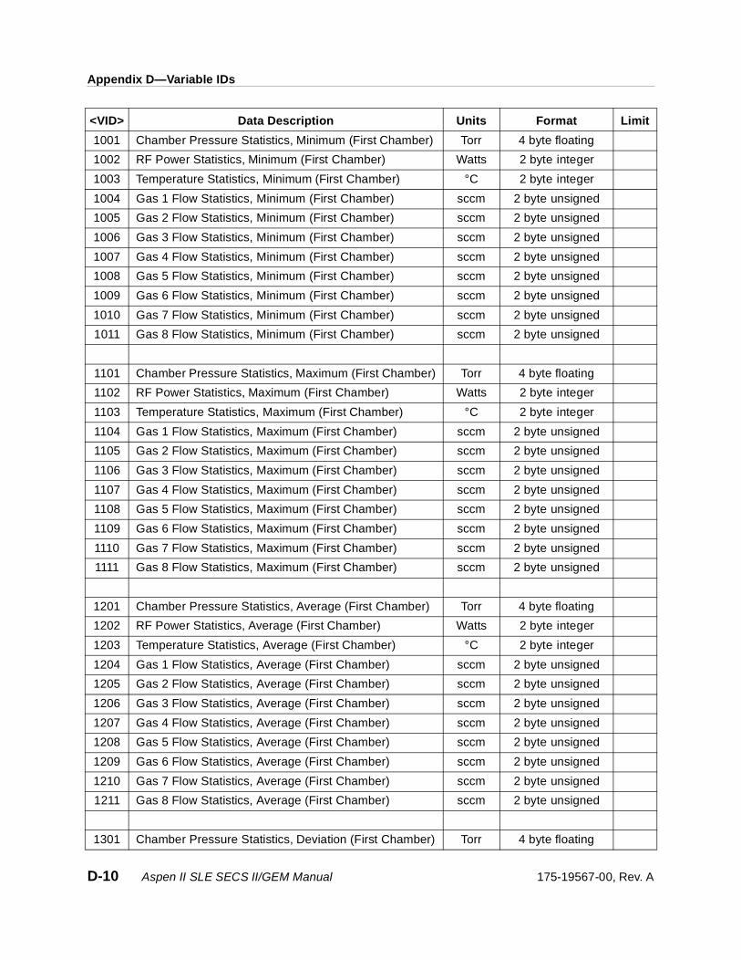
Appendix D—Variable IDs
1001 Chamber Pressure Statistics, Minimum (First Chamber) Torr 4 byte floating
1002 RF Power Statistics, Minimum (First Chamber) Watts 2 byte integer
1003 Temperature Statistics, Minimum (First Chamber) °C 2 byte integer
1004 Gas 1 Flow Statistics, Minimum (First Chamber) sccm 2 byte unsigned
1005 Gas 2 Flow Statistics, Minimum (First Chamber) sccm 2 byte unsigned
1006 Gas 3 Flow Statistics, Minimum (First Chamber) sccm 2 byte unsigned
1007 Gas 4 Flow Statistics, Minimum (First Chamber) sccm 2 byte unsigned
1008 Gas 5 Flow Statistics, Minimum (First Chamber) sccm 2 byte unsigned
1009 Gas 6 Flow Statistics, Minimum (First Chamber) sccm 2 byte unsigned
1010 Gas 7 Flow Statistics, Minimum (First Chamber) sccm 2 byte unsigned
1011 Gas 8 Flow Statistics, Minimum (First Chamber) sccm 2 byte unsigned
1101 Chamber Pressure Statistics, Maximum (First Chamber) Torr 4 byte floating
1102 RF Power Statistics, Maximum (First Chamber) Watts 2 byte integer
1103 Temperature Statistics, Maximum (First Chamber) °C 2 byte integer
1104 Gas 1 Flow Statistics, Maximum (First Chamber) sccm 2 byte unsigned
1105 Gas 2 Flow Statistics, Maximum (First Chamber) sccm 2 byte unsigned
1106 Gas 3 Flow Statistics, Maximum (First Chamber) sccm 2 byte unsigned
1107 Gas 4 Flow Statistics, Maximum (First Chamber) sccm 2 byte unsigned
1108 Gas 5 Flow Statistics, Maximum (First Chamber) sccm 2 byte unsigned
1109 Gas 6 Flow Statistics, Maximum (First Chamber) sccm 2 byte unsigned
1110 Gas 7 Flow Statistics, Maximum (First Chamber) sccm 2 byte unsigned
1111 Gas 8 Flow Statistics, Maximum (First Chamber) sccm 2 byte unsigned
1201 Chamber Pressure Statistics, Average (First Chamber) Torr 4 byte floating
1202 RF Power Statistics, Average (First Chamber) Watts 2 byte integer
1203 Temperature Statistics, Average (First Chamber) °C 2 byte integer
1204 Gas 1 Flow Statistics, Average (First Chamber) sccm 2 byte unsigned
1205 Gas 2 Flow Statistics, Average (First Chamber) sccm 2 byte unsigned
1206 Gas 3 Flow Statistics, Average (First Chamber) sccm 2 byte unsigned
1207 Gas 4 Flow Statistics, Average (First Chamber) sccm 2 byte unsigned
1208 Gas 5 Flow Statistics, Average (First Chamber) sccm 2 byte unsigned
1209 Gas 6 Flow Statistics, Average (First Chamber) sccm 2 byte unsigned
1210 Gas 7 Flow Statistics, Average (First Chamber) sccm 2 byte unsigned
1211 Gas 8 Flow Statistics, Average (First Chamber) sccm 2 byte unsigned
1301 Chamber Pressure Statistics, Deviation (First Chamber) Torr 4 byte floating
<VID> Data Description Units Format Limit
D-10 Aspen II SLE SECS II/GEM Manual 175-19567-00, Rev. A

Appendix D—Variable IDs
1302 RF Power Statistics, Deviation (First Chamber) Watts 2 byte integer
1303 Temperature Statistics, Deviation (First Chamber) °C 2 byte integer
1304 Gas 1 Flow Statistics, Deviation (First Chamber) sccm 2 byte unsigned
1305 Gas 2 Flow Statistics, Deviation (First Chamber) sccm 2 byte unsigned
1306 Gas 3 Flow Statistics, Deviation (First Chamber) sccm 2 byte unsigned
1307 Gas 4 Flow Statistics, Deviation (First Chamber) sccm 2 byte unsigned
1308 Gas 5 Flow Statistics, Deviation (First Chamber) sccm 2 byte unsigned
1309 Gas 6 Flow Statistics, Deviation (First Chamber) sccm 2 byte unsigned
1310 Gas 7 Flow Statistics, Deviation (First Chamber) sccm 2 byte unsigned
1311 Gas 8 Flow Statistics, Deviation (First Chamber) sccm 2 byte unsigned
*2001 Chamber Pressure Statistics, Minimum (Second Chamber)
Torr 4 byte floating
*2002 RF Power Statistics, Minimum (Second Chamber) Watts 2 byte integer
*2003 Temperature Statistics, Minimum (Second Chamber) °C 2 byte integer
*2004 Gas 1 Flow Statistics, Minimum (Second Chamber) sccm 2 byte unsigned
*2005 Gas 2 Flow Statistics, Minimum (Second Chamber) sccm 2 byte unsigned
*2006 Gas 3 Flow Statistics, Minimum (Second Chamber) sccm 2 byte unsigned
*2007 Gas 4 Flow Statistics, Minimum (Second Chamber) sccm 2 byte unsigned
*2008 Gas 5 Flow Statistics, Minimum (Second Chamber) sccm 2 byte unsigned
*2009 Gas 6 Flow Statistics, Minimum (Second Chamber) sccm 2 byte unsigned
*2010 Gas 7 Flow Statistics, Minimum (Second Chamber) sccm 2 byte unsigned
*2011 Gas 8 Flow Statistics, Minimum (Second Chamber) sccm 2 byte unsigned
*2101 Chamber Pressure Statistics, Maximum (Second Chamber)
Torr 4 byte floating
*2102 RF Power Statistics, Maximum (Second Chamber) Watts 2 byte integer
*2103 Temperature Statistics, Maximum (Second Chamber) °C 2 byte integer
*2104 Gas 1 Flow Statistics, Maximum (Second Chamber) sccm 2 byte unsigned
*2105 Gas 2 Flow Statistics, Maximum (Second Chamber) sccm 2 byte unsigned
*2106 Gas 3 Flow Statistics, Maximum (Second Chamber) sccm 2 byte unsigned
*2107 Gas 4 Flow Statistics, Maximum (Second Chamber) sccm 2 byte unsigned
*2108 Gas 5 Flow Statistics, Maximum (Second Chamber) sccm 2 byte unsigned
*2109 Gas 6 Flow Statistics, Maximum (Second Chamber) sccm 2 byte unsigned
*2110 Gas 7 Flow Statistics, Maximum (Second Chamber) sccm 2 byte unsigned
*2111 Gas 8 Flow Statistics, Maximum (Second Chamber) sccm 2 byte unsigned
<VID> Data Description Units Format Limit
175-19567-00, Rev. A Aspen II SLE SECS II/GEM Manual D-11

Appendix D—Variable IDs
The above <VID> numbers can be used in S1F3, S2F33, and S6F3 for getting equipment status and defining a report.
* The second chamber's Variable IDs are only valid in dual chamber systems. If a system is configured with only one chamber, no matter on which side the chamber is mounted, the second chamber's Variable IDs will be invalid. The Aspen system always uses the first set of Variable IDs for single-chamber systems.
For dual-chamber systems, the first chamber is assigned to the RIGHT chamber and the second chamber is assigned to the BACK chamber.
*2201 Chamber Pressure Statistics, Average (Second Chamber)
Torr 4 byte floating
*2202 RF Power Statistics, Average (Second Chamber) Watts 2 byte integer
*2203 Temperature Statistics, Average (Second Chamber) °C 2 byte integer
*2204 Gas 1 Flow Statistics, Average (Second Chamber) sccm 2 byte unsigned
*2205 Gas 2 Flow Statistics, Average (Second Chamber) sccm 2 byte unsigned
*2206 Gas 3 Flow Statistics, Average (Second Chamber) sccm 2 byte unsigned
*2207 Gas 4 Flow Statistics, Average (Second Chamber) sccm 2 byte unsigned
*2208 Gas 5 Flow Statistics, Average (Second Chamber) sccm 2 byte unsigned
*2209 Gas 6 Flow Statistics, Average (Second Chamber) sccm 2 byte unsigned
*2210 Gas 7 Flow Statistics, Average (Second Chamber) sccm 2 byte unsigned
*2211 Gas 8 Flow Statistics, Average (Second Chamber) sccm 2 byte unsigned
*2301 Chamber Pressure Statistics, Deviation (Second Chamber)
Torr 4 byte floating
*2302 RF Power Statistics, Deviation (Second Chamber) Watts 2 byte integer
*2303 Temperature Statistics, Deviation (Second Chamber) °C 2 byte integer
*2304 Gas 1 Flow Statistics, Deviation (Second Chamber) sccm 2 byte unsigned
*2305 Gas 2 Flow Statistics, Deviation (Second Chamber) sccm 2 byte unsigned
*2306 Gas 3 Flow Statistics, Deviation (Second Chamber) sccm 2 byte unsigned
*2307 Gas 4 Flow Statistics, Deviation (Second Chamber) sccm 2 byte unsigned
*2308 Gas 5 Flow Statistics, Deviation (Second Chamber) sccm 2 byte unsigned
*2309 Gas 6 Flow Statistics, Deviation (Second Chamber) sccm 2 byte unsigned
*2310 Gas 7 Flow Statistics, Deviation (Second Chamber) sccm 2 byte unsigned
*2311 Gas 8 Flow Statistics, Deviation (Second Chamber) sccm 2 byte unsigned
<VID> Data Description Units Format Limit
D-12 Aspen II SLE SECS II/GEM Manual 175-19567-00, Rev. A

Appendix E—Remote Commands
The available Aspen Remote Commands are as follows:
<RCMD> Description <CPNAME> <CPVAL>
TOP Set the Top Wafer Number of the Outer Cassettes in Wafer Location Mode.
WAFER 2 byte unsigned1-25/26
BOTTOM Set the Bottom Wafer Number of the Outer Cassettes in Wafer Location Mode.
WAFER 2 byte unsigned1-25/26
LEFT Set the number of wafers of the Left Outer Cassette in Wafer Count Mode.
WAFER 2 byte unsigned0-25/26
RIGHT Set the number of wafers of the Right Outer Cassette in Wafer Count Mode.
WAFER 2 byte unsigned0-25/26
RECIPE Set the outer cassettes recipe with number or name.
NUMBER or NAME
2 byte unsigned 1-99 or max.25 byte ASCII
ROUTING Set the outer cassettes route with number. NUMBER 2 byte unsigned1-99
RUN CONTINUOUS Select Run Continuous in the RUN MENU without parameters.
RUN SINGLE Select Run Single in the RUN MENU without parameters.
HOLD Hold System command without parameters.
CONTINUE Resume System command without parameters.
ABORT Reset System command without parameters.
NO CASSETTES No more cassettes to load without parameters.
SIGNAL_TOWER Control Signal Tower Lights on, off and flash.
REDYELLOWGREENBLUE
1 byte ASCII0 = Turn Off1 = Turn On2 = Flash
OPEN DOOR Open the cassette door without parameters. Aspen has to be in either Full-Auto or Semi-Auto Mode and Remote Mode. Command is not available with SMIF installations.
CLOSE DOOR Close the cassette door without parameters. Aspen has to be in either Full-Auto or Semi-Auto Mode and Remote Mode. Command is not available with SMIF installations.
MANUAL Go to Manual Mode without parameters.
175-19567-00, Rev. A Aspen II SLE SECS II/GEM Manual E-1

Appendix E—Remote Commands
SEMI-AUTO Go to Semi-Auto Mode without parameters.
FULL-AUTO Go to Full-Auto Mode without parameters.
LOAD CASSETTE Load one or two cassettes from pods. (SMIF)
PORT 1 byte binary
1= Left Cassette2= Right Cassette3= Both Cassettes
UNLOAD CASSETTE
Unload one or two cassettes to pods. (SMIF)
PORT 1 byte binary
1= Left Cassette2= Right Cassette3= Both Cassettes
BACK RECIPE Selects the Back Chamber for uploading or downloading recipes for the S7 Stream.
RIGHT RECIPE Selects the Right Chamber for uploading or downloading recipes for the S7 Stream.
SKIP EMPTY In Wafer Locations mode, skip any empty slots found by the paddle sensors.
NO EMPTY SLOT In Wafer Locations mode, do not skip any empty slots found by the paddle sensors.
OPERATOR Set operator ID for VID95 ID 18 byte ASCII
BUZZER ON Turn on buzzer without parameters.
BUZZER OFF Turn off buzzer without parameters.
LEAK TEST Start Leak Test without parameters.
ENGINEER-MODE Go to Engineering Mode without parameters. The system must be idle and mconf Mode Change must be enabled.
SELECTION Same function as the Operation Keys. KEY 2 byte integer
1-6
LOCK POD Lock one or two pods. (SMIF) PORT 1 byte binary
1= Left Pod2= Right Pod3= Both Pods
UNLOCK POD Unlock one or two pods. (SMIF) PORT 1 byte binary
1= Left Pod2= Right Pod3= Both Pods
ACCEPT MAP Confirm wafer mapping data without parameters.
<RCMD> Description <CPNAME> <CPVAL>
E-2 Aspen II SLE SECS II/GEM Manual 175-19567-00, Rev. A

Appendix E—Remote Commands
REJECT MAP Reject wafer mapping data without parameters.
SINGLE CASSETTE Confirm single cassette operation without parameters.
HEX Set Hex Option in CN page:
1 = 1H = Extension Exercise4 =4H = Lift Exercise16 =10H = No Pin Search64 = 40H = Robot Exercise256 = 100H = Display Wafer Map512 = 200H = No Gas Checking1024 = 400H = Auto Marathon Operator2048 = 800H = No Wafer on Pad Check8192 = 2000H = Inhibit RF Power Check16384 = 4000H = Read End Point32768 = 8000H = Exercise Atmosphere
OPTION 2 byte unsigned
0 - 65535
ACTIVE Define the Active Chamber only on a dual-chamber system. It also selects which chamber receives the wafer first if not in routing mode or a parallel route if in routing mode.
CHAMBER 2 byte unsigned
1= Side Chamber2= Back Chamber
SLOT MAP Send Wafer Map from Host to Aspen to use for wafer processing.
Port 1 (left)Port 2 (right)
Binary 00 or 01 to Max. Wafer Count 25 or 26
RESET Resets CN and CN C page counters for Wafers Processed and RF Hours.
(Note: Reset hours on the desired chamber by first selecting it with the ACTIVE command.)
RF HOURSRF HOURS2RF HOURS3RF HOURS4RF HOURS5
WAFS PROCWAFS PROC1WAFS PROC2WAFS PROC3WAFS PROC4WAFS PROC5
2 byte unsigned0 - 32767
4 byte integer0 - 2 Billion
<RCMD> Description <CPNAME> <CPVAL>
175-19567-00, Rev. A Aspen II SLE SECS II/GEM Manual E-3

Appendix E—Remote Commands
E-4 Aspen II SLE SECS II/GEM Manual 175-19567-00, Rev. A

Appendix F—Remote Control Operation
The Aspen Equipment is switched from Engineering Mode to Remote Mode by typing <TR> toggle remote on the equipment keyboard. The status screen will then display "Remote Mode." The Aspen can be returned to the Engineering Mode by typing <TR>. The Host can switch the Aspen to Remote Mode with the S2F41 Remote Command.
While in the remote control mode, the Aspen SECS II software tracks the state and status of the equipment by receiving state transition information from the equipment control software and then replying with the appropriate equipment control messages at the proper time. All of the control information is generated with the Aspen/SECS II software, while the host only supplies material handling and processing recipe information. The host can determine which of the three modes, Engineering, Operator, or Remote, the equipment is currently in by using Variable ID 25.
The equipment has two ports. When viewed from the front of the system, the first port is assigned to the left cassette, which has an ID of "1". The second port is assigned to the right cassette, which has an ID of "2". All requested processing recipes must reside on the Aspen system disk before they can be used for processing.
While in Remote Mode, with the host responding to the Aspen system that it has no more cassettes to process, the cassette door will remain open. To close the cassette door for some reason, the operator must change the Aspen to Operator Mode and select the option from the front panel screen. To resume the Remote Mode, the operator must change the Aspen system to Semi-Auto or Full-Auto Mode, and the cassette door will open automatically.
If the host is not using S4Fx (S4F1 / S4F17) to unload the cassettes, please disregard the next section.
Using S4 Functions to Remove Cassettes from the Aspen Equipment
The Aspen system has finished processing the wafers and the cassettes are in the cassette nest and ready to be removed from the Aspen system.
After the wafers have been processed, the Aspen will swap the inner and outer cassettes, backfill the shuttle and open the cassette door. The host can detect the event of Unload Material Request, obtain the status of the outer cassettes, and initiate the Material Transfer Request function by issuing S4F17 with Port ID to the Aspen equipment.
The Aspen will accept the message S4F17 if the Aspen equipment is in Remote Control Mode and there is a finished cassette at the specified port waiting for the transfer; otherwise, the Aspen will acknowledge with an error to the host. Then, the Aspen sends a S4F1 message, Ready to Send Material, to the host and waits for the acknowledge. When the host is ready to receive the cassette, a message S4F3 will be sent to the Aspen Equipment. Upon the receipt of S4F3, the Aspen follows the status of the cassette to be removed. If the T1 timeout occurs before the removal of the cassette, the Aspen will send S4F9, Stuck in Sender, and S4F7, Not Ready to Send, to the host, so the host can stop its transfer mechanism. If the Aspen detects that the cassette is gone but fails to receive S4F5 before the T3 timeout, a message, S4F13, Send Incomplete Receiver, will be sent to the host.
If the second port also requires a cassette to be unloaded, the host should initiate the transfer sequence again.
If the host is not using S4Fx (S4F1 / S4F17) to load the cassettes, disregard the next section.
175-19567-00, Rev. A Aspen II SLE SECS II/GEM Manual F-1

Appendix F—Remote Control Operation Using S4 Functions to Insert Cassettes into the Aspen
Using S4 Functions to Insert Cassettes into the Aspen Equipment
If the Aspen finds a port available to receive the material, the Aspen sends a message S4F17 (Request to Receive Material) with Port ID, Request to Receive Material, to the host and waits for a reply.
If the host acknowledges the message and sends a message S4F1, Ready to Send, to the Aspen, the Aspen will send a message S4F3, Send Material, to advise the host that it is ready to receive material. If the Aspen detects that the material has been transferred at the specified port, two messages, S4F5 and S4F15, which are Handshake Complete and Material Received, will be sent to the host and the Aspen will stop the transfer mechanism. If material is not received before the T3 timeout, the Aspen sends a S4F11 message, Stuck in Receiver, to the host.
If a S4F18, Request to Receive Acknowledge, message, which is the response of the S4F17, Request to Receive Material, message, indicates that the host is busy, the Aspen will wait for a minute and initiate the transfer again.
If a message S4F7, Not Ready to Send, is received by the Aspen which indicates that no material is being sent to the Aspen equipment, the Aspen monitor will display "Host Has No Cass. To Send At Port #". and sends a message S4F5, Handshake Complete, to the host. If none of two ports is loaded with material, Aspen will wait for a minute and initiate the transfer again.
If the material is loaded, the Aspen will then display "Caution Cassette Door Will Be Closing" on the monitor screen. This message will remain on the screen for 10 seconds and then the cassette door will begin to close.
If the Aspen detects that the cassettes are loaded without a Material ID, the Aspen will send S3F11, Material ID Request, to the host.
Cassettes Transfer Without S4 Messages
The Aspen will not initiate the S4F17, Request to Receive Material, message and other S4 messages. In this case, the Aspen will ignore any S4 messages sent by the host. The host may send Material ID Send (S3F13) after the cassette has been manually loaded at the specified port.
Aspen Requests to Open Cassette Door
An Event (39) will be sent to the host. If the Aspen is in Remote and Full-Auto or Semi-Auto mode, the host may send an OPEN DOOR command with S2F41, Host Command Send, to open the cassette door. Otherwise, the operator must press the panel button or palm buttons to open the door.
Wafer Location Requests
1. Aspen Requests Top Wafer Number
An Event (33) will be sent to the host to request the Top Wafer Number. The Aspen will wait for the host to send S2F41, Host Command Send, with TOP command and WAFER number.
2. Aspen Requests Bottom Wafer Number
An Event (34) will be sent to the host to request the Bottom Wafer Number. The Aspen will wait for the host to send S2F41, Host Command Send, with BOTTOM command and WAFER number.
F-2 Aspen II SLE SECS II/GEM Manual 175-19567-00, Rev. A

Wafer Location Requests Appendix F—Remote Control Operation
3. Aspen Requests Wafer Counts
An Event (68) will be sent to the host to request the Left Wafer Count and an Event (69) to request the Right Wafer Count. The Aspen will wait for the host to send S2F41 with the wafer counts.
Note If the Aspen tool has Wafer Mapping set to “Mattson” or “Receive from Host”, in the mconf screen, the Aspen system will not request any wafer data. It will go directly to the Route/Recipe Select screen after the cassettes are loaded.
“Mattson” Wafer Mapping: Once the “Run” command has been issued, the tool will map the wafers and send the information to the host computer while the cassette door is closing if Mattson wafer mapping hardware is installed.
“From Host” Wafer Mapping: The wafer map can be sent anytime before the cassette door is closed. The Aspen system will request the map from the host if it has not been received before the cassette door is closed with Event 152.
4. Aspen Requests Recipe Name, Number or Route Number
An Event (35) will be sent to the host. The Aspen will wait for the host to send S2F41 (Host Command Send) with RECIPE command and NUMBER or NAME. The Aspen will also accept S2F27, Initiate Process Request. If a zero length PPID of S2F27 (Initiate Process Report) is found, the Aspen will use the current outer recipe number. If in routing mode, an Event (48) will be sent to the host. The Aspen will wait for the host to send the S2F41 ROUTING command with NUMBER.
5. Aspen Requests Run Selection
An Event (38) will be sent to the host. The Aspen will wait for the host to send the S2F41 (Host Command Send) with RUN CONTINUOUS or RUN SINGLE command.
6. Aspen Requests to Close Cassette Door
An Event (45) will be sent to the host. If the Aspen is in Remote and Full-Auto or Semi-Auto Mode, the host may send the CLOSE DOOR command using S2F41 (Host Command Send) to close the cassette door; otherwise, the operator must press the panel button or palm buttons to close the door.
7. Aspen Requests Wafer Map Data and Reports Mapping Completed
If wafer mapping is set to “receive from host”, the Aspen sends Event (152) to request data if the data has not been received yet. If wafer mapping is set to “Mattson”, then wafer mapping is accomplished as the cassette door closes. Both Mattson Wafer Mapping and Wafer Map from Host will send Event (86) Wafer Mapping Completed.
8. Remote Command to Control the Operation
The host may also send the Remote Command Send (S2F21 or S2F41) to pause, reset, stop and resume the equipment operation.
175-19567-00, Rev. A Aspen II SLE SECS II/GEM Manual F-3
Appendix F—Remote Control Operation Wafer Location Requests
F-4 Aspen II SLE SECS II/GEM Manual 175-19567-00, Rev. A
Appendix G—Process Program Body Description (PPBODY)
This is repeated for all 10 steps.
13000 Pressure (mTorr)
350 RF Power (Watts)
150 RF Time (dec sec)
50 Delay Time (dec sec)
0 Spare
2000 Gas 1 Flow (sccm)
0 Gas 2 Flow (sccm)
0 Gas 3 Flow (sccm)
0 Gas 4 Flow (sccm)
0 Gas 5 Flow (sccm)
0 Gas 6 Flow (sccm)
0 Gas 7 Flow (sccm)
0 Gas 8 Flow (sccm)
0 End Point (integer)
0 Process Attributes (integer)
0 Endpoint Detector Type (integer)
0 Sensitivity Scale (integer)
0 Input Channel (integer)
0 Endpoint Delay Time (integer)
0 Upslope Value (integer)
0 Downslope Value (integer)
0 Maximum Debounce Count (integer)
0 Final Threshold (integer)
0 Spare
0 Spare
0 Spare
0 Spare
0 Spare
0 Spare
0 Spare
0 Spare
0 Spare
0 Spare
0 Spare
0 Spare
0 Spare
175-19567-00, Rev. A Aspen II SLE SECS II/GEM Manual G-1

Appendix G—Process Program Body Description (PPBODY)
G-2 Aspen II SLE SECS II/GEM Manual 175-19567-00, Rev. A

Appendix H—Formatted Process Program
An example of the Formatted Process Program of the Aspen II system using SLE software is shown below:
Structure:L,4
1. <PPID> (A25)2. <MDLN> (A6)3. <SOFTREV> (A6)4. L,11
1. L,21. <CCODE> (U2)2. L,14PPARM1. <TEMPERATURE> (I2)PPARM2. <PRECONRECIPE> (I2)PPARM3. <PRECONFREQ> (I2)PPARM4. <NUMBERSTEP> (I2)PPARM5. <RESERVED> (I4)PPARM6. <RESERVED> (I4)PPARM7. <RESERVED> (I4)PPARM8. <RESERVED> (I4)PPARM9. <RESERVED> (I4)PPARM10. <RESERVED> (I4)PPARM11. <RESERVED> (I4)PPARM12. <RESERVED> (I4)PPARM13. <RESERVED> (I4)PPARM14. <RESERVED> (I4)
Note The following step is repeated a total of ten times to represent each recipe step..
2. L,21. <CCODE> (U2)2. L,36PPARM1. <PRESURE> (I4)PPARM2. <RF POWER> (I2)PPARM3. <RF TIME> (U2)PPARM4. <RF DELAY TIME> (U2)PPARM5. <RESERVED> (U2)PPARM6. <GAS FLOW 1> (U2)PPARM7. <GAS FLOW 2> (U2)PPARM8. <GAS FLOW 3> (U2)PPARM9. <GAS FLOW 4> (U2)PPARM10. <GAS FLOW 5> (U2)PPARM11. <GAS FLOW 6> (U2)PPARM12. <GAS FLOW 7> (U2)PPARM13. <GAS FLOW 8> (U2)PPARM14. <ENDPOINT> (U2)PPARM15. <ATTRIBUTE> (U2)PPARM16. <EPD INSTALL> (I2)PPARM17. <SCALE/SENSITIVITY> (I2)PPARM18. <EP CHANNEL> (I2)PPARM19. <START DELAY TIME> (I2)PPARM20. <UPSLOPE THRESHOLD> (I2)PPARM21. <DOWNSLOPE THRESHOLD>(I4)PPARM22. <PEAK DEBOUNCE> (I4)
175-19567-00, Rev. A Aspen II SLE SECS II/GEM Manual H-1
Appendix H—Formatted Process Program
PPARM23. <FINAL THRESHOLD> (I2)PPARM24. <MINIMUM PROCESS TIME> (I2)PPARM25. <FLAT PEAK DEVIATION> (I2)PPARM26. <FLAT PEAK COUNT> (I2)PPARM27. <MINIMUM CHANGE> (I2)PPARM28. <EP GAIN LEFT A> (I2)PPARM29. <EP GAIN LEFT B> (I2)PPARM30. <EP GAIN RIGHT A> (I2)PPARM31. <EP GAIN RIGHT B> (I2)PPARM32. <RESERVED> (I2)PPARM33. <RESERVED> (I2)PPARM34. <RESERVED> (I2)PPARM35. <RESERVED> (I2)PPARM36. <RESERVED> (I2)
H-2 Aspen II SLE SECS II/GEM Manual 175-19567-00, Rev. A
Appendix I—Programming Examples
S2F15 New Equipment Constant Send
<L<L [2]
<U2 0> * ECID: Retry host timer.<I2 60> * ECV: Seconds
><L [2]
<U2 1> * ECID: Annotated Reports.<BOOLEAN T> * ECV: Enabled.
><L [2]
<U2 2> * ECID: Send material timer.<I2 10> * ECV: Seconds
><L [2]
<U2 3> * ECID: Receive material timer.<I2 60> * ECV: Seconds
><L [2]
<U2 4> * ECID Handshake time-out timer.<I2 70> * ECV Seconds
>> .
S2F23 Trace Initialize Send
<L [5]<U2 1><A '000100'><U2 10000><U2 1><L
<U2 10> * SVID Set temperature<U2 17> * SVID Actual temperature<U2 13> * SVID Actual process pressure<U2 19> * SVID Actual loadlock pressure<U2 20> * SVID Actual shuttle pressure
> > .
S2F23 Delete Trace Send
<L [5]<U2 1><A '000000'><U2 0><U2 1><L>
>.
175-19567-00, Rev. A Aspen II SLE SECS II/GEM Manual I-1

Appendix I—Programming Examples S3F13 Material ID Send
S3F13 Material ID Send
<L [2]<B 01><A '090491STD4VAC'>
> .
S2F33 Define Report Send
<L [2]<U2 1> * Data ID No. 1.<L [1]
<L [2]<U2 1> * Report ID No. 1.<L [6]
<U2 0> * Variable Data ID No. 0.<U2 18> * Variable Data ID No. 18.<U2 13> * Variable Data ID No. 13.<U2 14> * Variable Data ID No. 13.<U2 11> * Variable Data ID No. 11.<U2 17> * Variable Data ID No. 17.
>>
>>.
S2F35 Link Event Send
<L [2]<U2 1> * Data ID No. 1.
<L<L [2]
<U2 4> * Event ID No. 4. [RF ON]<L [1]
<U2 1> * Report ID No. 1.>
>>
>.
S2F37 Enable All Events Send
<L [2]<BOOLEAN T><L>
>.
I-2 Aspen II SLE SECS II/GEM Manual 175-19567-00, Rev. A
Appendix J—Event Report Configuration File Structure
File "CUST??.RPT" contains the defined event report records. The customer ID number will be used to fill the "??" in the file name. For example, the file name will be "CUST99.RPT" for customer ID 99. The structure of the record is as follows:
DATAID, PFCD, CEID, DSID, VID, VID, VID......
All IDs are in numeric format.
The same CEID may be assigned in more than one record. The Aspen will link them into one report.
If the Aspen cannot find the file or the CEID in the file, the Aspen will search the host-defined report generated by S2F33, S2F35 and S2F37 upon the occurrence of an enabled event.
175-19567-00, Rev. A Aspen II SLE SECS II/GEM Manual J-1

Appendix J—Event Report Configuration File Structure
J-2 Aspen II SLE SECS II/GEM Manual 175-19567-00, Rev. A

175-19567-00, Rev. A Aspen II SLE SECS II/GEM Manual K-1
Appendix K—Material Handling Diagram
Wait First CassetteLoaded
Wait for SecondCassette Loaded
Load CassettesBegin Here
Send Event 22 –Load Material
Request
Load anyCassette ?
InnerCassette?
Send Event 33 or68 - Top Wafer
Request or LeftWafer Count
Wait for Top Wafor Left Cass CountS2F41 from Host
Send Event 34 or69-Bottom Wafer or Right Wafer Count
Wait for BottomWafer or Right
Cass Count (S2F41)
Send Event 35/48 –Recipe/Route
Request
Wait for Recipe /Route Assigned by
Host (S2F41)
Send Event 38 –Run Request
Wait RunCommand fromHost (S2F41)
Send Event 45 –Prompt to Close
Door
RemoteControlDoor?
Wait for CloseCommand fromHost (S2F41)
Close CassetteDoor and Pump
Down
Send Event 13 or37 – Cassette
Loaded
2nd Cassetteto load?
Send Event 13 or37 – Cassette
Loaded
Send Event 23 –Loading Material
Complete
Ready to ReceiveMID for Left or
Left & RightCassettes
Door CloseAutomatically?
Yes
Yes
No
No
Yes
N
No
o
Yes
Load Cassette Flow
Send S2F41 NoCassettes or Push Key
Send S2F41 NoCassettes
No
Yes
Figure K-1. Load Cassette Software Flow
Earl Boggs
Earl Boggs

Appendix K—Material Handling Diagram
K-2 Aspen II SLE SECS II/GEM Manual 175-19567-00, Rev. A
Open Cassette Door
Door CloseAutomatically?
RemoteControlDoor?
Unload Cassette FlowUnload Cassettes
Begin Here
Yes
Yes
Yes
No
No
No
Send Event 39 –Prompt to OpenCassette Door
Wait for Host Open Door Command
(S2F41)
Wait for Second Cassette
to be removed
Any CassetteLeft?
Send Event 12 or 36 –Cassette Removed Send Event 21 –
Unload Material
LoadCassette
Send Event 12 or 36 –Cassette Removed
Wait for First Cassetteto be removed
Send Event 20 –Unload Material
Request
Figure K-2. Unload Cassette Software Flow
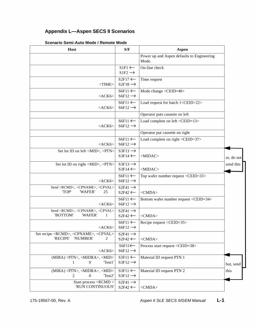
, do not
nd this
t, send
is
Appendix L—Aspen SECS II Scenarios
Scenario Semi-Auto Mode / Remote Mode
Host S/F Aspen
Power up and Aspen defaults to Engineering Mode.
S1F1 ←S1F2 →
On-line check
<TIME>S2F17 ←S2F18 →
Time request
<ACK6>S6F11 ←S6F12 →
Mode change <CEID=40>
<ACK6>S6F11 ←S6F12 →
Load request for batch 1<CEID=22>
Operator puts cassette on left
<ACK6>S6F11 ←S6F12 →
Load complete on left <CEID=13>
Operator put cassette on right
<ACK6>S6F11 ←S6F12 →
Load complete on right <CEID=37>
Set lot ID on left <MID>, <PTN> S3F13 →S3F14 ← <MIDAC> or
Set lot ID on right <MID>, <PTN> S3F13 →S3F14 ← <MIDAC>
se
<ACK6>S6F11 ←S6F12 →
Top wafer number request <CEID=33>
Send <RCMD>, <CPNAME>, <CPVAL>'TOP'xxxx'WAFER'xxxx25xxx
S2F41 →S2F42 ← <CMDA>
<ACK6>S6F11 ←S6F12 →
Bottom wafer number request <CEID=34>
Send <RCMD>, <CPNAME>, <CPVAL>'BOTTOM'xxxx'WAFER'xxxx1xxx
S2F41 →S2F42 ← <CMDA>
<ACK6>S6F11 ←S6F12 →
Recipe request <CEID=35>
Set recipe <RCMD>, <CPNAME>, <CPVAL>'RECIPE'xx'NUMBER'xxxxxx2xxx
S2F41 →S2F42 ← <CMDA>
<ACK6>S6F11←S6F12 →
Process start request <CEID=38>
(MIRA) <PTN>, <MIDRA>, <MID>1xxxxxxx0xxxxxx'Test1'
S3F11 ←S3F12 →
Material ID request PTN 1
bu
(MIRA) <PTN>, <MIDRA>, <MID>2xxxxxxx0xxxxxx'Test2'
S3F11 ←S3F12 →
Material ID request PTN 2 th
Start process <RCMD >'RUN CONTINUOUS'
S2F41 →S2F42 ← <CMDA>
175-19567-00, Rev. A Aspen II SLE SECS II/GEM Manual L-1
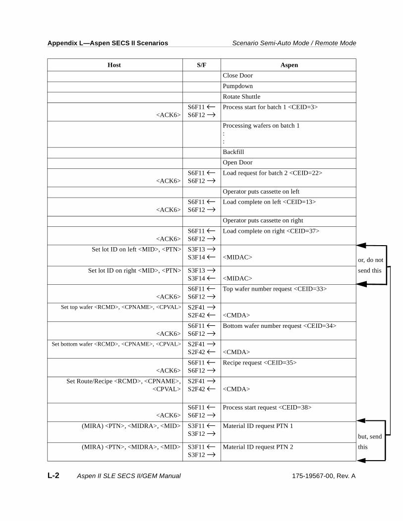
Appendix L—Aspen SECS II Scenarios Scenario Semi-Auto Mode / Remote Mode
, do not
nd this
t, send
is
Close Door
Pumpdown
Rotate Shuttle
<ACK6>S6F11 ←S6F12 →
Process start for batch 1 <CEID=3>
Processing wafers on batch 1::
Backfill
Open Door
<ACK6>S6F11 ←S6F12 →
Load request for batch 2 <CEID=22>
Operator puts cassette on left
<ACK6>S6F11 ←S6F12 →
Load complete on left <CEID=13>
Operator puts cassette on right
<ACK6>S6F11 ←S6F12 →
Load complete on right <CEID=37>
Set lot ID on left <MID>, <PTN> S3F13 →S3F14 ← <MIDAC> or
Set lot ID on right <MID>, <PTN> S3F13 →S3F14 ← <MIDAC>
se
<ACK6>S6F11 ←S6F12 →
Top wafer number request <CEID=33>
Set top wafer <RCMD>, <CPNAME>, <CPVAL> S2F41 →S2F42 ← <CMDA>
<ACK6>S6F11 ←S6F12 →
Bottom wafer number request <CEID=34>
Set bottom wafer <RCMD>, <CPNAME>, <CPVAL> S2F41 →S2F42 ← <CMDA>
<ACK6>S6F11 ←S6F12 →
Recipe request <CEID=35>
Set Route/Recipe <RCMD>, <CPNAME>,<CPVAL>
S2F41 →S2F42 ← <CMDA>
<ACK6>S6F11 ←S6F12 →
Process start request <CEID=38>
(MIRA) <PTN>, <MIDRA>, <MID> S3F11 ←S3F12 →
Material ID request PTN 1
bu
(MIRA) <PTN>, <MIDRA>, <MID> S3F11 ←S3F12 →
Material ID request PTN 2 th
Host S/F Aspen
L-2 Aspen II SLE SECS II/GEM Manual 175-19567-00, Rev. A
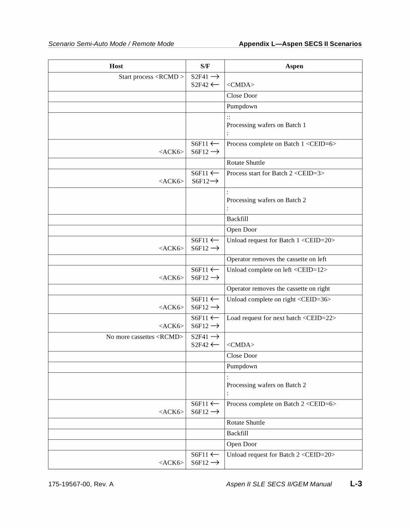
Scenario Semi-Auto Mode / Remote Mode Appendix L—Aspen SECS II Scenarios
Start process <RCMD > S2F41 →S2F42 ← <CMDA>
Close Door
Pumpdown
::Processing wafers on Batch 1:
<ACK6>S6F11 ←S6F12 →
Process complete on Batch 1 <CEID=6>
Rotate Shuttle
<ACK6>S6F11 ←S6F12→
Process start for Batch 2 <CEID=3>
:Processing wafers on Batch 2:
Backfill
Open Door
<ACK6>S6F11 ←S6F12 →
Unload request for Batch 1 <CEID=20>
Operator removes the cassette on left
<ACK6>S6F11 ←S6F12 →
Unload complete on left <CEID=12>
Operator removes the cassette on right
<ACK6>S6F11 ←S6F12 →
Unload complete on right <CEID=36>
<ACK6>S6F11 ←S6F12 →
Load request for next batch <CEID=22>
No more cassettes <RCMD> S2F41 →S2F42 ← <CMDA>
Close Door
Pumpdown
:Processing wafers on Batch 2:
<ACK6>S6F11 ←S6F12 →
Process complete on Batch 2 <CEID=6>
Rotate Shuttle
Backfill
Open Door
<ACK6>S6F11 ←S6F12 →
Unload request for Batch 2 <CEID=20>
Host S/F Aspen
175-19567-00, Rev. A Aspen II SLE SECS II/GEM Manual L-3

Appendix L—Aspen SECS II Scenarios Scenario Semi-Auto Mode / Remote Mode
Operator removes the cassette on left
<ACK6>S6F11 ←S6F12 →
Unload complete on left <CEID=12>
Operator removes the cassette on right
<ACK6>S6F11 ←S6F12 →
Unload complete on right <CEID=36>
Host S/F Aspen
L-4 Aspen II SLE SECS II/GEM Manual 175-19567-00, Rev. A

Scenario Full-Auto Mode/AGV Mode Appendix L—Aspen SECS II Scenarios
Scenario Full-Auto Mode/AGV Mode
Host S/F Aspen
Power up and Aspen defaults to Engineering Mode.
S1F1 ←S1F2 →
On-line check
<TIME>S2F17 ←S2F18 →
Time request
<ACK6>S6F11 ←S6F12 →
Mode change <CEID=40>
<ACK6>S6F11 ←S6F12 →
AGV load request on left <CEID=97>(Batch 1)
<ACK6>S6F11 ←S6F12 →
AGV load request on right <CEID=98>(Batch 1)
Host commands the AGV to move to Aspen
Aspen
Left cassette loaded
CS_0 ←CS_1 ←CS_2 ←VALID ←L_REQ →TR_REQ ←READY →BUSY ←COMPT ←
AGVLeft cassette transfer
<ACK6>S6F11 ←S6F12 →
AGV load complete on left <CEID=93>
Aspen
Right cassette loaded
CS_0 ←CS_1 ←CS_2 ←VALID ←L_REQ →TR_REQ ←READY →BUSY ←COMPT ←
AGVRight cassette transfer
<ACK6>S6F11 ←S6F12 →
AGV load complete on right <CEID=94>
Set lot ID on left <MID>, <PTN> S3F13 →S3F14 ← <MIDAC>
Set lot ID on right <MID>, <PTN> S3F13 →S3F14 ← <MIDAC>
<ACK6>S6F11 ←S6F12 →
Top wafer number request <CEID=33>
175-19567-00, Rev. A Aspen II SLE SECS II/GEM Manual L-5
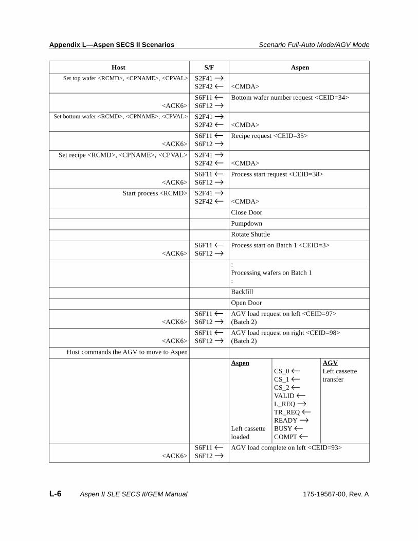
Appendix L—Aspen SECS II Scenarios Scenario Full-Auto Mode/AGV Mode
Set top wafer <RCMD>, <CPNAME>, <CPVAL> S2F41 →S2F42 ← <CMDA>
<ACK6>S6F11 ←S6F12 →
Bottom wafer number request <CEID=34>
Set bottom wafer <RCMD>, <CPNAME>, <CPVAL> S2F41 →S2F42 ← <CMDA>
<ACK6>S6F11 ←S6F12 →
Recipe request <CEID=35>
Set recipe <RCMD>, <CPNAME>, <CPVAL> S2F41 →S2F42 ← <CMDA>
<ACK6>S6F11 ←S6F12 →
Process start request <CEID=38>
Start process <RCMD> S2F41 →S2F42 ← <CMDA>
Close Door
Pumpdown
Rotate Shuttle
<ACK6>S6F11 ←S6F12 →
Process start on Batch 1 <CEID=3>
:Processing wafers on Batch 1:
Backfill
Open Door
<ACK6>S6F11 ←S6F12 →
AGV load request on left <CEID=97>(Batch 2)
<ACK6>S6F11 ←S6F12 →
AGV load request on right <CEID=98>(Batch 2)
Host commands the AGV to move to Aspen
Aspen
Left cassette loaded
CS_0 ←CS_1 ←CS_2 ←VALID ←L_REQ →TR_REQ ←READY →BUSY ←COMPT ←
AGVLeft cassette transfer
<ACK6>S6F11 ←S6F12 →
AGV load complete on left <CEID=93>
Host S/F Aspen
L-6 Aspen II SLE SECS II/GEM Manual 175-19567-00, Rev. A
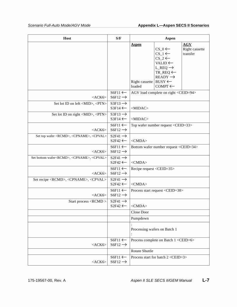
Scenario Full-Auto Mode/AGV Mode Appendix L—Aspen SECS II Scenarios
Aspen
Right cassette loaded
CS_0 ←CS_1 ←CS_2 ←VALID ←L_REQ →TR_REQ ←READY →BUSY ←COMPT ←
AGVRight cassette transfer
<ACK6>S6F11 ←S6F12 →
AGV load complete on right <CEID=94>
Set lot ID on left <MID>, <PTN> S3F13 →S3F14 ← <MIDAC>
Set lot ID on right <MID>, <PTN> S3F13 →S3F14 ← <MIDAC>
<ACK6>S6F11 ←S6F12 →
Top wafer number request <CEID=33>
Set top wafer <RCMD>, <CPNAME>, <CPVAL> S2F41 →S2F42 ← <CMDA>
<ACK6>S6F11 ←S6F12 →
Bottom wafer number request <CEID=34>
Set bottom wafer<RCMD>, <CPNAME>, <CPVAL> S2F41 →S2F42 ← <CMDA>
<ACK6>S6F11 ←S6F12 →
Recipe request <CEID=35>
Set recipe <RCMD>, <CPNAME>, <CPVAL> S2F41 →S2F42 ← <CMDA>
<ACK6>S6F11 ←S6F12 →
Process start request <CEID=38>
Start process <RCMD > S2F41 →S2F42 ← <CMDA>
Close Door
Pumpdown
:Processing wafers on Batch 1:
<ACK6>S6F11 ←S6F12 →
Process complete on Batch 1 <CEID=6>
Rotate Shuttle
<ACK6>S6F11 ←S6F12 →
Process start for batch 2 <CEID=3>
Host S/F Aspen
175-19567-00, Rev. A Aspen II SLE SECS II/GEM Manual L-7

Appendix L—Aspen SECS II Scenarios Scenario Full-Auto Mode/AGV Mode
:Processing wafers on Batch 2:
Backfill
Open Door
<ACK6>S6F11 ←S6F12 →
AGV unload request on left <CEID=95>(Batch 1)
<ACK6>S6F11 ←S6F12 →
AGV unload request on right <CEID=96>(Batch 1)
Host commands the AGV to move to Aspen
Aspen
Left cassette removed
CS_0 ←CS_1 ←CS_2 ←VALID ←UN_REQ →TR_REQ ←READY →BUSY ←COMPT ←
AGVLeft cassette transfer
<ACK6>S6F11 ←S6F12 →
AGV unload complete on left <CEID=91>
Aspen
Right cassette removed
CS_0 ←CS_1 ←CS_2 ←VALID ←UN_REQ →TR_REQ ←READY →BUSY ←COMPT ←
AGVRight cassette transfer
<ACK6>S6F11 ←S6F12 →
AGV unload complete on right <CEID=92>
<ACK6>S6F11 ←S6F12 →
AGV load request on left <CEID=97>(Next Batch)
<ACK6>S6F11 ←S6F12 →
AGV load request on right <CEID=98>(Next batch)
No more cassettes <RCMD> S2F41 →S2F42 ← <CMDA>
Close Door
Pumpdown
Host S/F Aspen
L-8 Aspen II SLE SECS II/GEM Manual 175-19567-00, Rev. A

Scenario Full-Auto Mode/AGV Mode Appendix L—Aspen SECS II Scenarios
:Processing wafers on Batch 2:
<ACK6>S6F11 ←S6F12 →
Process complete on Batch 2 <CEID=6>
Rotate Shuttle
Backfill
Open Door
<ACK6>S6F11 ←S6F12 →
AGV unload request on left <CEID=95>(Batch 2)
<ACK6>S6F11 ←S6F12 →
AGV unload request on right <CEID=96>(Batch 2)
Host commands the AGV to move to Aspen
Aspen
Left cassette removed
CS_0 ←CS_1 ←CS_2 ←VALID ←UN_REQ →TR_REQ ←READY →BUSY ←COMPT ←
AGVLeft cassette transfer
<ACK6>S6F11 ←S6F12 →
AGV unload complete on left <CEID=91>
Aspen
Right cassette remove
CS_0 ←CS_1 ←CS_2 ←VALID ←UN_REQ →TR_REQ ←READY →BUSY ←COMPT ←
AGVRight cassette transfer
<ACK6>S6F11 ←S6F12→
AGV unload complete on right <CEID=92>
Host S/F Aspen
175-19567-00, Rev. A Aspen II SLE SECS II/GEM Manual L-9

Appendix L—Aspen SECS II Scenarios Scenario Full-Auto Mode/AGV Mode
L-10 Aspen II SLE SECS II/GEM Manual 175-19567-00, Rev. A

Appendix M—SML File
Note The following is a transcript of the strip.sml file for the Aspen Strip System. The actual strip.sml file can be obtained from Mattson Technology by sending an email request to [email protected]. It is also supplied on the Aspen II Strip Electronic Documentation CDROM.
Note Lines beginning with an asterisk (*) in this file are comments that should not be compiled when the file is used.
*****************************************************************************
** Mattson Technology Incorporated
** Copyright (c) 1997. All Rights Reserved
**
** DESCRIPTION: STRIP SML FILE
** Version 1.3
**
** Modification Log:
** DATE INITIALS VERSION DESCRIPTION
** 06/18/97 CRB1 1.3 Changed the header.
** 05/13/97 CRB1 1.2 Added S1F15 New Equipment Constant Send (ECS)
** Messages, Added S2F65 Reset Spooling Streams
** and Functions testing, Added S6F65 Request
** Spooled Data (RSD), Added S2F41 'WHITE' and
** 'BLUE' light commands, Made an old and a new
** S2F37 Enable Event Reports for older code testing
** 05/11/97 CRB1 1.1 Added S1F9 Material Transfer Status Request (TSR)
** Added S1F11 Status Variable Namelist (SVNR)
** Added S2F13 Zero length for all Equipment Constants
** 04/17/97 CRB1 1.0 Added Asyst SMIF 2200 LPT robot commands to S2F41
** 'LOCK POD'
** 'UNLOCK POD'
** 'LOAD CASSETTE'
** 'UNLOAD CASSETTE'
** Alarm Event # 16, 'SMIF LOADER ERROR'
** CEID's
** 100 - Left Pod put on
** 101 - Right Pod put on
** 102 - Load Left Cassette request
** 103 - Load Right Cassette request
** 104 - Loader load left complete
** 105 - Loader load right complete
** 106 - Loader unload left request
** 107 - Loader unload right request
** 108 - Loader unload left complete
** 109 - Loader unload right complete
175-19567-00, Rev. A Aspen II SLE SECS II/GEM Manual M-1
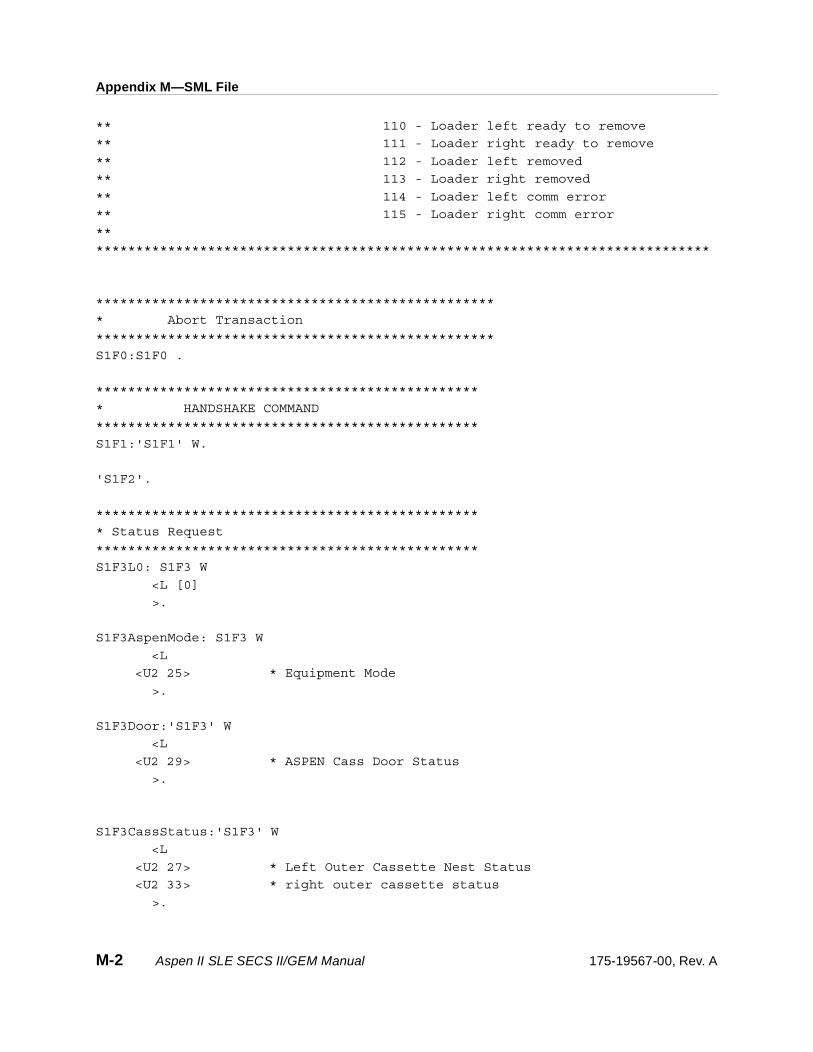
Appendix M—SML File
** 110 - Loader left ready to remove
** 111 - Loader right ready to remove
** 112 - Loader left removed
** 113 - Loader right removed
** 114 - Loader left comm error
** 115 - Loader right comm error
**
*****************************************************************************
**************************************************
* Abort Transaction
**************************************************
S1F0:S1F0 .
************************************************
* HANDSHAKE COMMAND
************************************************
S1F1:'S1F1' W.
'S1F2'.
************************************************
* Status Request
************************************************
S1F3L0: S1F3 W
<L [0]
>.
S1F3AspenMode: S1F3 W
<L
<U2 25> * Equipment Mode
>.
S1F3Door:'S1F3' W
<L
<U2 29> * ASPEN Cass Door Status
>.
S1F3CassStatus:'S1F3' W
<L
<U2 27> * Left Outer Cassette Nest Status
<U2 33> * right outer cassette status
>.
M-2 Aspen II SLE SECS II/GEM Manual 175-19567-00, Rev. A

Appendix M—SML File
S1F3ChamberStatus:'S1F3' W
<L
<U2 25> * ASPEN Equipment Mode
<U2 27> * Left Outer Cassette Nest Status
<U2 33> * right outer cassette status
<U2 44> * SIDE CHAMBER status
<U2 76> * BACK CHAMBER status
>.
S1F3PortStatusLeft:'S1F3' W
<L
<U2 27> * Left Outer Cassette Nest Status
>.
S1F3PortStatusRight:'S1F3' W
<L
<U2 33> * right outer cassette status
>.
S1F3All:'S1F3' W
<L [43]
<U2 0> *Date & Time
<U2 1> *Processing Recipe Name
<U2 2> *Processing Recipe step.
<U2 3> *RF Power setting
<U2 4> *Proc Press setting
<U2 5> *RF time setting
<U2 6> *Gas 1 Flow setting
<U2 7> *Gas 2 Flow setting
<U2 8> *Gas 3 Flow setting
<U2 9> *Proc Delay Time
<U2 10> *Temperature setting
<U2 11> *RF Fwd Power Actual
<U2 12> *RF Elapse Time Act.
<U2 13> *Proc Press Actual
<U2 14> *Gas 1 Flow Actual
<U2 15> *Gas 2 Flow Actual
<U2 16> *Gas 3 Flow Actual
<U2 17> *Temperature Actual
<U2 18> *Current Wafer No.
<U2 19> *Load Lock Press.
<U2 20> *Shuttle Press.
<U2 21> *Left Outer Material ID Nest[0]
<U2 22> *Right Outer Material ID Nest[1]
<U2 23> *Left Inner Material ID Nest[0]
<U2 24> *Right Inner Material ID Nest[1]
175-19567-00, Rev. A Aspen II SLE SECS II/GEM Manual M-3

Appendix M—SML File
<U2 25> *ASPEN Equipment Mode
<U2 26> *ASPEN Equipment Status
<U2 27> *Left Outer Cassette Nest Status
<U2 28> *Left Inner Cassette Nest Status
<U2 29> *Cassette Door Status
<U2 30> *RF Rev Power Actual
<U2 31> *RF Rev Power Actual
<U2 32> *Right Wafer # in Chamber
<U2 33> * right outer cassette status
<U2 34> * right inner cassette status
<U2 49> *Chamber location of preceding
<U2 100> *Total Wafers
<U2 101> *Pin Search Data
<U2 200> *Spool Count Actual
<U2 201> *Spool Count Total
<U2 202> *Spool Start Time
<U2 203> *Spool Full Time
<U2 204> *Spool State
>.
*********************************************
* STATUS REQUEST
*********************************************
S1F3SecsStatus:'S1F3' W
<L
<U2 0> *Date & Time
<U2 5> *RF time setting
<U2 9> *Proc Delay Time
<U2 12> *RF Elapse Time Act.
<U2 31> *end point
>.
*********************************************
* HEX OPTION REQUEST
*********************************************
S1F3HexOption:'S1F3' W
<L
<U2 80> *HEX Option
>.
*********************************************
* CIDs REQUEST
*********************************************
S1F3Cid1:'S1F3' W
<L
<U2 91> *CID 1
M-4 Aspen II SLE SECS II/GEM Manual 175-19567-00, Rev. A

Appendix M—SML File
>.
S1F3Cid2:'S1F3' W
<L
<U2 92> *CID 2
>.
S1F3Cid3:'S1F3' W
<L
<U2 93> *CID 3
>.
S1F3Cid4:'S1F3' W
<L
<U2 94> *CID 4
>.
S1F3CidAll:'S1F3' W
<L
<U2 91> *CID 1
<U2 92> *CID 2
<U2 93> *CID 3
<U2 94> *CID 4
>.
S1F3Mid1:'S1F3' W
<L
<U2 21> *MID 1
>.
S1F3Mid2:'S1F3' W
<L
<U2 22> *MID 2
>.
S1F3Mid3:'S1F3' W
<L
<U2 23> *MID 3
>.
S1F3Mid4:'S1F3' W
<L
<U2 24> *MID 4
>.
S1F3MidAll:'S1F3' W
175-19567-00, Rev. A Aspen II SLE SECS II/GEM Manual M-5
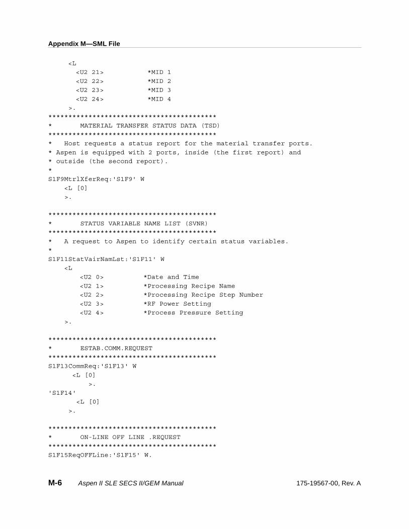
Appendix M—SML File
<L
<U2 21> *MID 1
<U2 22> *MID 2
<U2 23> *MID 3
<U2 24> *MID 4
>.
******************************************
* MATERIAL TRANSFER STATUS DATA (TSD)
******************************************
* Host requests a status report for the material transfer ports.
* Aspen is equipped with 2 ports, inside (the first report) and
* outside (the second report).
*
S1F9MtrlXferReq:'S1F9' W
<L [0]
>.
******************************************
* STATUS VARIABLE NAME LIST (SVNR)
******************************************
* A request to Aspen to identify certain status variables.
*
S1F11StatVairNamLst:'S1F11' W
<L
<U2 0> *Date and Time
<U2 1> *Processing Recipe Name
<U2 2> *Processing Recipe Step Number
<U2 3> *RF Power Setting
<U2 4> *Process Pressure Setting
>.
******************************************
* ESTAB.COMM.REQUEST
******************************************
S1F13CommReq:'S1F13' W
<L [0]
>.
'S1F14'
<L [0]
>.
******************************************
* ON-LINE OFF LINE .REQUEST
******************************************
S1F15ReqOFFLine:'S1F15' W.
M-6 Aspen II SLE SECS II/GEM Manual 175-19567-00, Rev. A
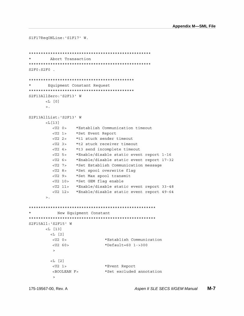
Appendix M—SML File
S1F17ReqONLine:'S1F17' W.
***************************************************
* Abort Transaction
***************************************************
S2F0:S2F0 .
********************************************
* Equipment Constant Request
********************************************
S2F13AllZero:'S2F13' W
<L [0]
>.
S2F13AllList:'S2F13' W
<L[13]
<U2 0> *Establish Communication timeout
<U2 1> *Set Event Report
<U2 2> *t1 stuck sender timeout
<U2 3> *t2 stuck receiver timeout
<U2 4> *t3 send incomplete timeout
<U2 5> *Enable/disable static event report 1-16
<U2 6> *Enable/disable static event report 17-32
<U2 7> *Set Establish Communication message
<U2 8> *Set spool overwrite flag
<U2 9> *Set Max spool transmit
<U2 10> *Set GEM flag enable
<U2 11> *Enable/disable static event report 33-48
<U2 12> *Enable/disable static event report 49-64
>.
*****************************************************
* New Equipment Constant
*****************************************************
S2F15All:'S2F15' W
<L [13]
<L [2]
<U2 0> *Establish Communication
<U2 60> *Default=60 1->300
>
<L [2]
<U2 1> *Event Report
<BOOLEAN F> *Set excluded annotation
>
175-19567-00, Rev. A Aspen II SLE SECS II/GEM Manual M-7

Appendix M—SML File
<L [2]
<U2 2> *S4F9 t1 sender timeout
<U2 10> *Default=10 1->3000
>
<L [2]
<U2 3> *S4F11 t2 receiver timeout
<U2 60> *Default=60
>
<L [2]
<U2 4> *S4F13 t3 incomplete timeout
<U2 60> *Default=60
>
<L [2]
<U2 5> *Disable Static event reports
<U2 0> *1 to 16
>
<L [2]
<U2 6> *Disable Static event report
<U2 0> *17 to 30
>
<L [2]
<U2 7> *Set Establish Communication OFF
<BOOLEAN F> *Not use S1F13
>
<L [2]
<U2 8> *Set spool overwrite flag
<BOOLEAN F> *
>
<L [2]
<U2 9> *Set Max spool transmit message value
<U2 1> *Default=250
>
<L [2]
<U2 10> *Set GEM flag OFF
<BOOLEAN F> *Not use S5F73
>
<L [2]
M-8 Aspen II SLE SECS II/GEM Manual 175-19567-00, Rev. A
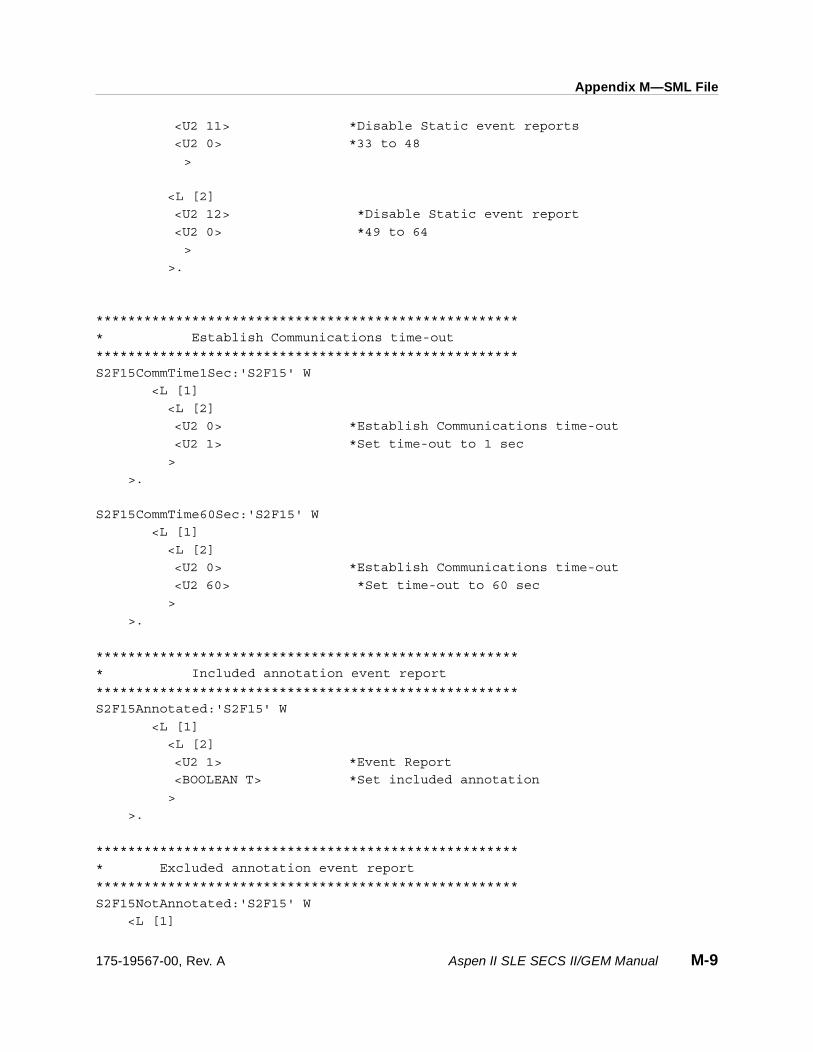
Appendix M—SML File
<U2 11> *Disable Static event reports
<U2 0> *33 to 48
>
<L [2]
<U2 12> *Disable Static event report
<U2 0> *49 to 64
>
>.
*****************************************************
* Establish Communications time-out
*****************************************************
S2F15CommTime1Sec:'S2F15' W
<L [1]
<L [2]
<U2 0> *Establish Communications time-out
<U2 1> *Set time-out to 1 sec
>
>.
S2F15CommTime60Sec:'S2F15' W
<L [1]
<L [2]
<U2 0> *Establish Communications time-out
<U2 60> *Set time-out to 60 sec
>
>.
*****************************************************
* Included annotation event report
*****************************************************
S2F15Annotated:'S2F15' W
<L [1]
<L [2]
<U2 1> *Event Report
<BOOLEAN T> *Set included annotation
>
>.
*****************************************************
* Excluded annotation event report
*****************************************************
S2F15NotAnnotated:'S2F15' W
<L [1]
175-19567-00, Rev. A Aspen II SLE SECS II/GEM Manual M-9

Appendix M—SML File
<L [2]
<U2 1> *Event Report
<BOOLEAN F> *Set excluded
>
>.
*****************************************************
* Spool Overwrite Flag
*****************************************************
S2F15SpoolOWOn:'S2F15' W
<L [1]
<L [2]
<U2 8> *Set Spool Overwrite flag ON
<BOOLEAN T>
>
>.
S2F15SpoolOWOff:'S2F15' W
<L [1]
<L [2]
<U2 8> *Set Spool Overwrite flag OFF
<BOOLEAN F>
>
>.
*****************************************************
* Max Spool Transmit
*****************************************************
S2F15SpoolXmit1:'S2F15' W
<L [1]
<L [2]
<U2 9> *Set Spool Xmit = 1 Message
<U2 1>
>
>.
S2F15SpoolXmit5:'S2F15' W
<L [1]
<L [2]
<U2 9> *Set Spool Xmit = 5 Message
<U2 5>
>
>.
S2F15SpoolXmit250:'S2F15' W
<L [1]
M-10 Aspen II SLE SECS II/GEM Manual 175-19567-00, Rev. A

Appendix M—SML File
<L [2]
<U2 9> *Set Spool Xmit = 250 Message
<U2 250>
>
>.
S2F15SpoolXmit999:'S2F15' W
<L [1]
<L [2]
<U2 9> *Set Spool Xmit = 999 Message
<U2 999>
>
>.
*****************************************************
* GEM flag on
*****************************************************
S2F15GemOn:'S2F15' W
<L [1]
<L [2]
<U2 10> *Set GEM flag ON
<BOOLEAN T>
>
>.
*****************************************************
* GEM flag off
*****************************************************
S2F15GemOff:'S2F15' W
<L [1]
<L [2]
<U2 10> *Set GEM flag OFF
<BOOLEAN F>
>
>.
*****************************************************
* Establish communication on
*****************************************************
S2F15s1f13On:'S2F15' W
<L [1]
<L [2]
<U2 7> *Set Establish Communication ON
<BOOLEAN T> *
>
>.
175-19567-00, Rev. A Aspen II SLE SECS II/GEM Manual M-11
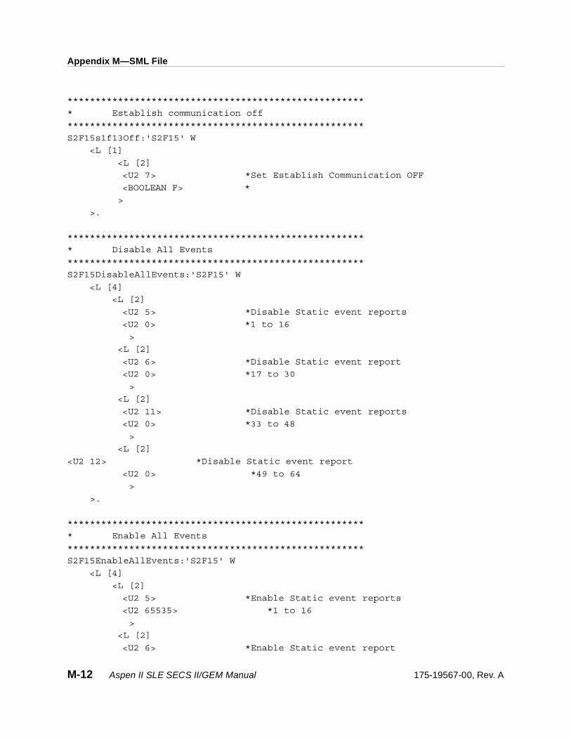
Appendix M—SML File
*****************************************************
* Establish communication off
*****************************************************
S2F15s1f13Off:'S2F15' W
<L [1]
<L [2]
<U2 7> *Set Establish Communication OFF
<BOOLEAN F> *
>
>.
*****************************************************
* Disable All Events
*****************************************************
S2F15DisableAllEvents:'S2F15' W
<L [4]
<L [2]
<U2 5> *Disable Static event reports
<U2 0> *1 to 16
>
<L [2]
<U2 6> *Disable Static event report
<U2 0> *17 to 30
>
<L [2]
<U2 11> *Disable Static event reports
<U2 0> *33 to 48
>
<L [2]
<U2 12> *Disable Static event report
<U2 0> *49 to 64
>
>.
*****************************************************
* Enable All Events
*****************************************************
S2F15EnableAllEvents:'S2F15' W
<L [4]
<L [2]
<U2 5> *Enable Static event reports
<U2 65535> *1 to 16
>
<L [2]
<U2 6> *Enable Static event report
M-12 Aspen II SLE SECS II/GEM Manual 175-19567-00, Rev. A

Appendix M—SML File
<U2 65535> *17 to 30
>
<L [2]
<U2 11> *Enable Static event reports
<U2 65535> *33 to 48
>
<L [2]
<U2 12> *Enable Static event report
<U2 65535> *49 to 64
>
>.
****************************************************
* DATE/TIME Request
****************************************************
S2F17:'S2F17' W.
******************************************
* Set Time and Date
******************************************
*'S2F18'
* <A '951121123456'>. *Time Or <A ‘2000113023590000’ > *16 bit
* SECS-SIM-Pro now handles this and returns
* dynamically the current date.
*
******************************************
* Remote Command Abort Send
******************************************
S2F21Abort:'S2F21' W
<L[1]
<U1 1> *RCMD 1=abort 2=continue 4=pause 6=stop
>.
******************************************
* Remote Command Continue Send
******************************************
S2F21Continue:'S2F21' W
<L[1]
<U1 2> *RCMD 1=abort 2=continue 4=pause 6=stop
>.
******************************************
* Remote Command Pause Send
******************************************
S2F21Pause:'S2F21' W
175-19567-00, Rev. A Aspen II SLE SECS II/GEM Manual M-13

Appendix M—SML File
<L[1]
<U2 4> *RCMD 1=abort 2=continue 4=pause 6=stop
>.
******************************************
* Remote Command STOP Send
******************************************
S2F21Stop:'S2F21' W
<L[1]
<U2 6> *RCMD 1=abort 2=continue 4=pause 6=stop
>.
*******************************************
* Trace Initialize Send (TIS)
*******************************************
Trace1:'S2F23' W
<L [5]
<U2 1> *TRID Trace Identification Number Trace ID = 1
<A '000001'> *Sample Period hhmmss = 1 second
<U2 10> *Number of Samples at the above period 10 samples
<U2 1> *Report Group Size = 1
<L
<U2 11> *RF Fwd Power Actual
<U2 12> *RF Elapse Time Act.
<U2 13> *Proc Press Actual
<U2 14> *Gas 1 Flow Actual
<U2 15> *Gas 2 Flow Actual
<U2 16> *Gas 3 Flow Actual
<U2 17> *Temperature Actual
<U2 19> *Load Lock Press.
<U2 20> *Shuttle Press.
<U2 30> *RF Rev Power Actual
>
>.
*******************************************
* Trace ON
*******************************************
S2F23Trace7:'S2F23' W
<L [5]
<U2 7> *Trace ID 7
<A '000001'> *Trace time 1 min.
<U2 15> *Total Wafer 10
<U2 1> *REPGSZ=1
<L [6]
<U2 0> *Date & Time
M-14 Aspen II SLE SECS II/GEM Manual 175-19567-00, Rev. A

Appendix M—SML File
<U2 200> *Spool Count Actual
<U2 201> *Spool Count Total
<U2 202> *Spool Start Time
<U2 203> *Spool Full Time
<U2 204> *Spool State
>
>.
S2F23TraceBackEndPoint:'S2F23' W
<L [5]
<U2 11> *Trace ID 11
<A '000001'> *Trace time 1 sec.
<U2 60> *Total traces 60
<U2 1> *REPGSZ=1
<L [4]
<U2 40> * CO
<U2 41> * O2
<U2 42> * CO
<U2 43> * O2
>
>.
S2F23TraceRightEndPoint:'S2F23' W
<L [5]
<U2 12> *Trace ID 12
<A '000001'> *Trace time 1 sec.
<U2 60> *Total traces 60
<U2 1> *REPGSZ=1
<L [4]
<U2 72> * CO
<U2 73> * O2
<U2 74> * CO
<U2 75> * O2
>
>.
S2F23TraceBackStopEndPoint:'S2F23' W
<L [5]
<U2 11> *Trace ID 11
<A '000001'> *Trace time 1 sec.
<U2 0> *Total traces 60
<U2 1> *REPGSZ=1
<L
>
>.
175-19567-00, Rev. A Aspen II SLE SECS II/GEM Manual M-15

Appendix M—SML File
S2F23TraceRightStopEndPoint:'S2F23' W
<L [5]
<U2 12> *Trace ID 12
<A '000001'> *Trace time 1 sec.
<U2 0> *Total traces 60
<U2 1> *REPGSZ=1
<L
>
>.
*******************************************
* Loopback Diag. Request
*******************************************
S2F25LoopbackDiag:'S2F25' W <B 0 1 2 4 8 16 32 64 80 FF>.
*******************************************
* Initial Process A Request
*******************************************
S2F27Test1:'S2F27' W
<L [3]
<U1 2>
<A 'TEST 1'> * PPID
<L [2]
<A 'CA0001-00'> * MID
<A 'CA0002-00'> * MID
>
>.
*******************************************
* Initial Process A Request
*******************************************
S2F27Test2A:'S2F27' W
<L [3]
<U1 2>
<A 'TEST 2'> * PPID
<L [2]
<A 'CA0001-00'> * MID
<A 'CA0002-00'> * MID
>
>.
*******************************************
* Initial Process B Request
*******************************************
S2F27Test2B:'S2F27' W
<L [3]
M-16 Aspen II SLE SECS II/GEM Manual 175-19567-00, Rev. A

Appendix M—SML File
<U1 2>
<A 'TEST 2'> * PPID
<L [2]
<A 'samsungmattsnlt1'> * MID
<A 'samsungmattsnlt2'> * MID
>
>.
******************************************
* Equip.Constant Namelist
******************************************
S2F29All:'S2F29' W
<L [13]
<U2 0> *Establish Communication timeout
<U2 1> *Set Event Report
<U2 2> *t1 stuck sender timeout
<U2 3> *t2 stuck receiver timeout
<U2 4> *t3 send incomplete timeout
<U2 5> *Enable/disable static event repot
<U2 6> *Enable/disable static event repot
<U2 7> *Set Establish Communication message
<U2 8> *Set spool overwrite flag
<U2 9> *Set Max spool transmit
<U2 10> *Set GEM flag enable
<U2 11> *Enable/disable event 33 to 48
<U2 12> *Enable/disable event 49 to 64
>.
***************************************
* Date & Time set Request
***************************************
S2F31:'S2F31' W
<A '95022220093000'>.
***************************************
* Define Report
***************************************
S2F33DefineReport:'S2F33' W
<L [2]
<U2 1> *Data ID
<L
<L [2]
<U2 1> *Load Request Report 1
<L [2]
<U2 21> *Left outer MID
175-19567-00, Rev. A Aspen II SLE SECS II/GEM Manual M-17

Appendix M—SML File
<U2 22> *Right outer MID
>
>
<L [2]
<U2 2> *Process Start - Report 2
<L [3]
<U2 21> *Left outer MID
<U2 22> *Right outer MID
<U2 1> *PPID
>
>
<L [2]
<U2 3> *Process End - Report 3
<L [3]
<U2 21> *Left outer MID
<U2 22> *Right outer MID
<U2 1> *PPID
>
>
<L [2]
<U2 4> *Unload Request - Report 4
<L [3]
<U2 21> *Left outer MID
<U2 22> *Right outer MID
<U2 1> *PPID
>
>
<L [2]
<U2 5> *Unload Left Cassette - Report 5
<L [2]
<U2 21> *Left Outer Cassette MID
<U2 22> *Right Outer Cassette MID
>
>
<L [2]
<U2 6> *Unload Right Cassette - Report 6
<L [2]
<U2 21> *Left Outer Cassette MID
<U2 22> *Right Outer Cassette MID
>
>
<L [2]
<U2 7> *Unload complete - Report 7
<L [2]
<U2 21> *Left Outer Cassette MID
<U2 22> *Right Outer Cassette MID
M-18 Aspen II SLE SECS II/GEM Manual 175-19567-00, Rev. A
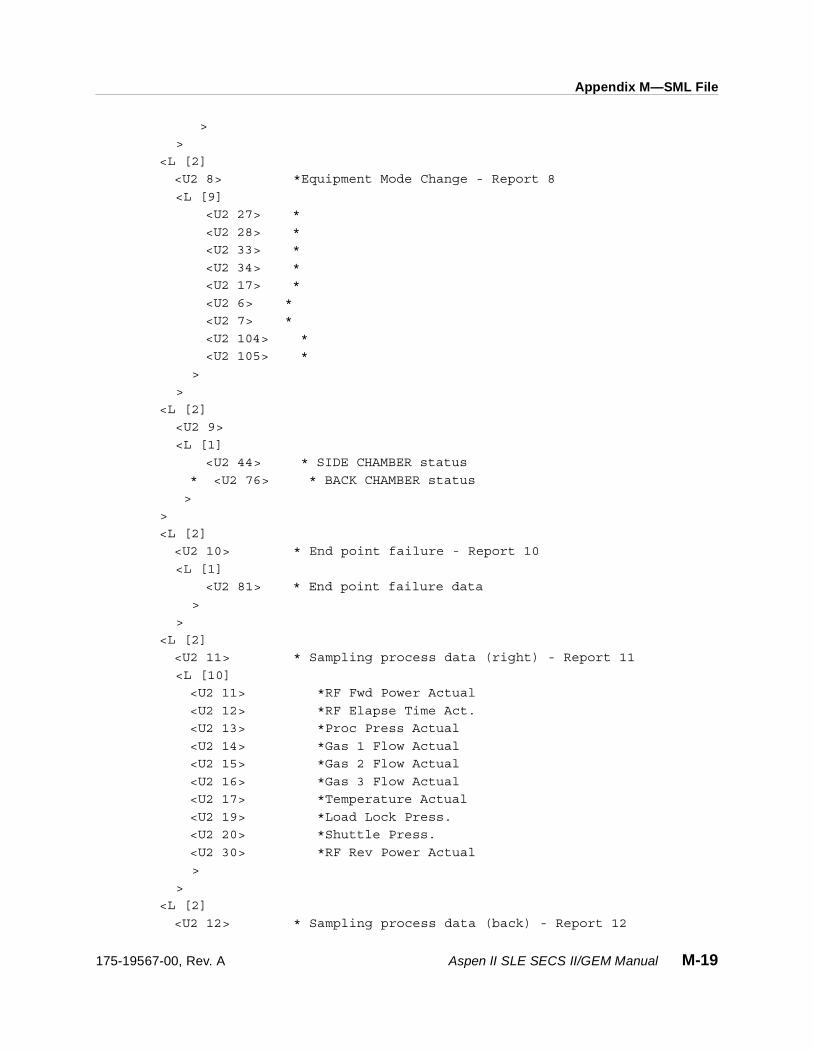
Appendix M—SML File
>
>
<L [2]
<U2 8> *Equipment Mode Change - Report 8
<L [9]
<U2 27> *
<U2 28> *
<U2 33> *
<U2 34> *
<U2 17> *
<U2 6> *
<U2 7> *
<U2 104> *
<U2 105> *
>
>
<L [2]
<U2 9>
<L [1]
<U2 44> * SIDE CHAMBER status
* <U2 76> * BACK CHAMBER status
>
>
<L [2]
<U2 10> * End point failure - Report 10
<L [1]
<U2 81> * End point failure data
>
>
<L [2]
<U2 11> * Sampling process data (right) - Report 11
<L [10]
<U2 11> *RF Fwd Power Actual
<U2 12> *RF Elapse Time Act.
<U2 13> *Proc Press Actual
<U2 14> *Gas 1 Flow Actual
<U2 15> *Gas 2 Flow Actual
<U2 16> *Gas 3 Flow Actual
<U2 17> *Temperature Actual
<U2 19> *Load Lock Press.
<U2 20> *Shuttle Press.
<U2 30> *RF Rev Power Actual
>
>
<L [2]
<U2 12> * Sampling process data (back) - Report 12
175-19567-00, Rev. A Aspen II SLE SECS II/GEM Manual M-19

Appendix M—SML File
<L [10]
<U2 11> *RF Fwd Power Actual
<U2 12> *RF Elapse Time Act.
<U2 13> *Proc Press Actual
<U2 14> *Gas 1 Flow Actual
<U2 15> *Gas 2 Flow Actual
<U2 16> *Gas 3 Flow Actual
<U2 17> *Temperature Actual
<U2 19> *Load Lock Press.
<U2 20> *Shuttle Press.
<U2 30> *RF Rev Power Actual
>
>
<L [2]
<U2 13> *Door open Report 13
<L [2]
<U2 21> *Left outer MID
<U2 22> *Right outer MID
>
>
<L [2]
<U2 14> *Door close Report 14
<L [2]
<U2 21> *Left outer MID
<U2 22> *Right outer MID
>
>
>
>.
***************************************
* Clear Define Report
***************************************
S2F33ClearReport:'S2F33' W
<L [2]
<U2 0> *Data ID
<L>
>.
**********************************************
* Link Event Report
**********************************************
S2F35LinkReport:'S2F35' W
<L [2]
M-20 Aspen II SLE SECS II/GEM Manual 175-19567-00, Rev. A

Appendix M—SML File
<U2 1> *DATA ID
<L
<L [2]
<U2 22> *Load Request
<L [1]
<U2 1> *Report ID 1
>
>
<L [2]
<U2 3> *Process Start
<L [1]
<U2 2> *Report ID 2
>
>
<L [2]
<U2 6> *Process End
<L [1]
<U2 3> *Report ID 3
>
>
<L [2]
<U2 20> *Unload Request
<L [1]
<U2 4> *Report ID 4
>
>
<L [2]
<U2 12> *Unload left Cassette
<L [1]
<U2 5> *Report ID 5
>
>
<L [2]
<U2 36> *Unload right Cassette
<L [1]
<U2 6> *Report ID 6
>
>
<L [2]
<U2 21> *Unload Complete
<L [1]
<U2 7> *Report ID 7
>
>
<L [2]
<U2 40> *Equipment Mode Changed
175-19567-00, Rev. A Aspen II SLE SECS II/GEM Manual M-21

Appendix M—SML File
<L [1]
<U2 8> *Report ID 8
>
>
<L [2]
<U2 43> *Chamber status changed
<L [1]
<U2 9> *Report ID 9
>
>
<L [2]
<U2 90> *Endpoint Failure
<L [1]
<U2 10> *Report ID 10
>
>
<L [2]
<U2 32> *Sampling process data (right)
<L [1]
<U2 11> *Report ID 11
>
>
<L [2]
<U2 50> *Sampling process data (back)
<L [1]
<U2 12> *Report ID 12
>
>
<L [2]
<U2 18> *door open
<L [1]
<U2 13> *Report ID 13
>
>
<L [2]
<U2 19> *door close
<L [1]
<U2 14> *Report ID 14
>
>
>
>.
*****************************************************
* En/Disable Event Report
*****************************************************
M-22 Aspen II SLE SECS II/GEM Manual 175-19567-00, Rev. A

Appendix M—SML File
S2F37EnableReportOld:'S2F37' W
<L [2]
<BOOLEAN T> *CEID
<L
<U2 3> *Process Started
<U2 6> *Process Complete
<U2 12> *left Cassette Removed
<U2 13> *left Cassette Inserted
<U2 14> *process step start
<U2 15> *process step end
<U2 16> *wafer process start
<U2 17> *wafer process end
<U2 18> *Door open
<U2 19> *Door close
<U2 20> *Unload Mat'l Complete
<U2 21> *Unloading Mat'l Request
<U2 22> *Load Mat'l Request
<U2 23> *Loading Mat'l Complete
<U2 33> *change to top wafer screen
<U2 34> *change to bottom wafer screen
<U2 35> *change to recipe number
<U2 36> *right cassette removed
<U2 37> *right cassette inserted
<U2 38> *request to run menu
<U2 40> *Equipment mode change
<U2 41> *Request to rotate inner cassette out
<U2 42> *idle timeout
<U2 43> *Chamber status
<U2 44> *Operator change to off-line
<U2 90> *End point failure
<U2 91> *AGV unload left complete
<U2 92> *AGV unload right complete
<U2 93> *AGV load left complete
<U2 94> *AGV load right complete
<U2 95> *AGV unload left request
<U2 96> *AGV unload right request
<U2 97> *AGV load left request
<U2 98> *AGV load right request
<U2 32> *Sampling process data (right)
<U2 50> *Sampling process data (back)
>
>.
S2F37EnableReport:'S2F37' W
<L [2]
<BOOLEAN T> *CEID
175-19567-00, Rev. A Aspen II SLE SECS II/GEM Manual M-23
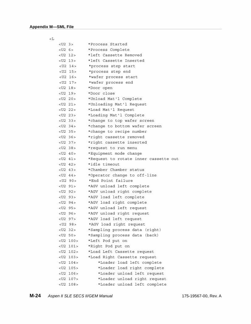
Appendix M—SML File
<L
<U2 3> *Process Started
<U2 6> *Process Complete
<U2 12> *left Cassette Removed
<U2 13> *left Cassette Inserted
<U2 14> *process step start
<U2 15> *process step end
<U2 16> *wafer process start
<U2 17> *wafer process end
<U2 18> *Door open
<U2 19> *Door close
<U2 20> *Unload Mat'l Complete
<U2 21> *Unloading Mat'l Request
<U2 22> *Load Mat'l Request
<U2 23> *Loading Mat'l Complete
<U2 33> *change to top wafer screen
<U2 34> *change to bottom wafer screen
<U2 35> *change to recipe number
<U2 36> *right cassette removed
<U2 37> *right cassette inserted
<U2 38> *request to run menu
<U2 40> *Equipment mode change
<U2 41> *Request to rotate inner cassette out
<U2 42> *idle timeout
<U2 43> *Chamber Chamber status
<U2 44> *Operator change to off-line
<U2 90> *End Point failure
<U2 91> *AGV unload left complete
<U2 92> *AGV unload right complete
<U2 93> *AGV load left complete
<U2 94> *AGV load right complete
<U2 95> *AGV unload left request
<U2 96> *AGV unload right request
<U2 97> *AGV load left request
<U2 98> *AGV load right request
<U2 32> *Sampling process data (right)
<U2 50> *Sampling process data (back)
<U2 100> *Left Pod put on
<U2 101> *Right Pod put on
<U2 102> *Load Left Cassette request
<U2 103> *Load Right Cassette request
<U2 104> *Loader load left complete
<U2 105> *Loader load right complete
<U2 106> *Loader unload left request
<U2 107> *Loader unload right request
<U2 108> *Loader unload left complete
M-24 Aspen II SLE SECS II/GEM Manual 175-19567-00, Rev. A
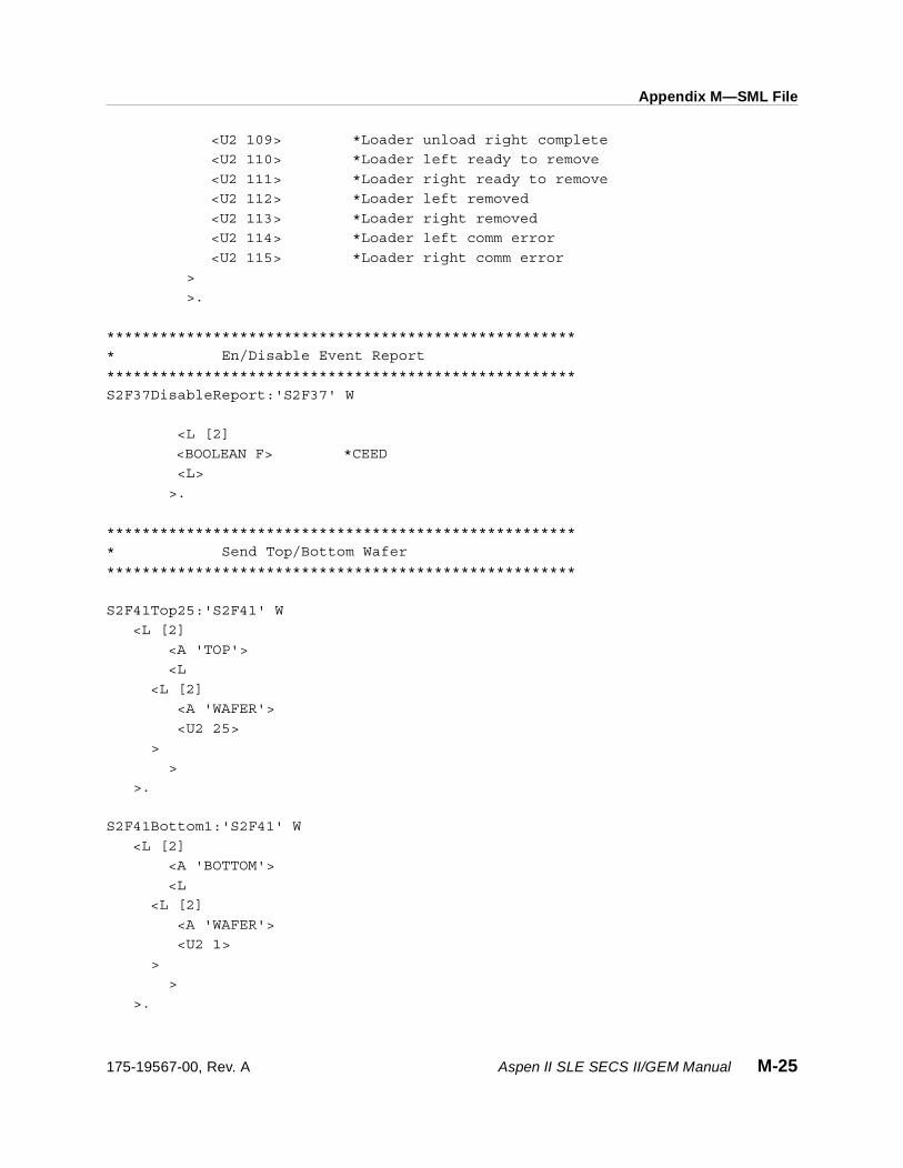
Appendix M—SML File
<U2 109> *Loader unload right complete
<U2 110> *Loader left ready to remove
<U2 111> *Loader right ready to remove
<U2 112> *Loader left removed
<U2 113> *Loader right removed
<U2 114> *Loader left comm error
<U2 115> *Loader right comm error
>
>.
*****************************************************
* En/Disable Event Report
*****************************************************
S2F37DisableReport:'S2F37' W
<L [2]
<BOOLEAN F> *CEED
<L>
>.
*****************************************************
* Send Top/Bottom Wafer
*****************************************************
S2F41Top25:'S2F41' W
<L [2]
<A 'TOP'>
<L
<L [2]
<A 'WAFER'>
<U2 25>
>
>
>.
S2F41Bottom1:'S2F41' W
<L [2]
<A 'BOTTOM'>
<L
<L [2]
<A 'WAFER'>
<U2 1>
>
>
>.
175-19567-00, Rev. A Aspen II SLE SECS II/GEM Manual M-25

Appendix M—SML File
S2F41Bottom25:'S2F41' W
<L [2]
<A 'BOTTOM'>
<L
<L [2]
<A 'WAFER'>
<U2 25>
>
>
>.
S2F41Bottom15:'S2F41' W
<L [2]
<A 'BOTTOM'>
<L
<L [2]
<A 'WAFER'>
<U2 15>
>
>
>.
*****************************************************
* SEND LEFT/RIGHT WAFER COUNTS
*****************************************************
S2F41Left25:'S2F41' W
<L [2]
<A 'LEFT'>
<L
<L [2]
<A 'WAFER'> /* Count Sent can be 0 – 26 */
<U2 25>
>
>
>.
S2F41Right4:'S2F41' W
<L [2]
<A 'RIGHT'>
<L
<L [2]
<A 'WAFER'>
<U2 4>
>
>
M-26 Aspen II SLE SECS II/GEM Manual 175-19567-00, Rev. A

Appendix M—SML File
>.
*****************************************************
* SEND RECIPE BY NUMBER OR NAME
*****************************************************
S2F41Recipe1:'S2F41' W
<L [2]
<A 'RECIPE'>
<L
<L [2]
<A 'NUMBER'>
<U2 1>
>
>
>.
S2F41Recipe2:'S2F41' W
<L [2]
<A 'RECIPE'>
<L
<L [2]
<A 'NUMBER'>
<U2 2>
>
>
>.
S2F41RecipeStripAll:'S2F41' W
<L [2]
<A 'RECIPE'>
<L
<L [2]
<A 'NAME'>
<A ‘STRIPALL’> /*Name must match existing recipe on tool*/
>
>
>.
*****************************************************
* SEND RUN COMMANDS
*****************************************************
S2F41RunContinous:'S2F41' W
<L [2]
<A 'RUN CONTINUOUS'>
<L
>
>.
175-19567-00, Rev. A Aspen II SLE SECS II/GEM Manual M-27
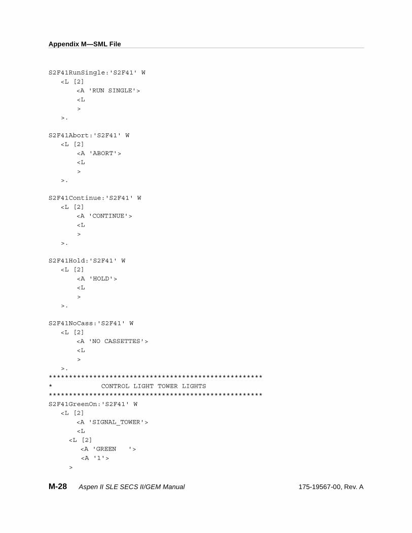
Appendix M—SML File
S2F41RunSingle:'S2F41' W
<L [2]
<A 'RUN SINGLE'>
<L
>
>.
S2F41Abort:'S2F41' W
<L [2]
<A 'ABORT'>
<L
>
>.
S2F41Continue:'S2F41' W
<L [2]
<A 'CONTINUE'>
<L
>
>.
S2F41Hold:'S2F41' W
<L [2]
<A 'HOLD'>
<L
>
>.
S2F41NoCass:'S2F41' W
<L [2]
<A 'NO CASSETTES'>
<L
>
>.
*****************************************************
* CONTROL LIGHT TOWER LIGHTS
*****************************************************
S2F41GreenOn:'S2F41' W
<L [2]
<A 'SIGNAL_TOWER'>
<L
<L [2]
<A 'GREEN '>
<A '1'>
>
M-28 Aspen II SLE SECS II/GEM Manual 175-19567-00, Rev. A
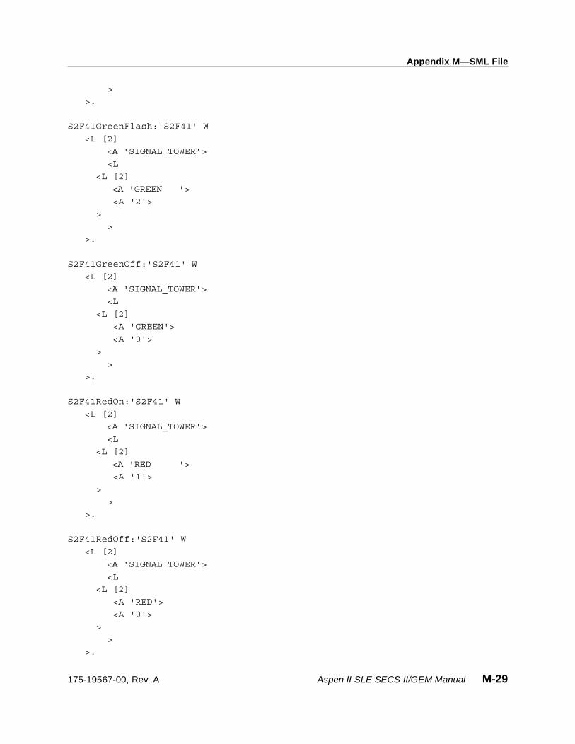
Appendix M—SML File
>
>.
S2F41GreenFlash:'S2F41' W
<L [2]
<A 'SIGNAL_TOWER'>
<L
<L [2]
<A 'GREEN '>
<A '2'>
>
>
>.
S2F41GreenOff:'S2F41' W
<L [2]
<A 'SIGNAL_TOWER'>
<L
<L [2]
<A 'GREEN'>
<A '0'>
>
>
>.
S2F41RedOn:'S2F41' W
<L [2]
<A 'SIGNAL_TOWER'>
<L
<L [2]
<A 'RED '>
<A '1'>
>
>
>.
S2F41RedOff:'S2F41' W
<L [2]
<A 'SIGNAL_TOWER'>
<L
<L [2]
<A 'RED'>
<A '0'>
>
>
>.
175-19567-00, Rev. A Aspen II SLE SECS II/GEM Manual M-29

Appendix M—SML File
S2F41RedFlash:'S2F41' W
<L [2]
<A 'SIGNAL_TOWER'>
<L
<L [2]
<A 'RED'>
<A '2'>
>
>
>.
S2F41YellowOn:'S2F41' W
<L [2]
<A 'SIGNAL_TOWER'>
<L
<L [2]
<A 'YELLOW '>
<A '1'>
>
>
>.
S2F41YellowOff:'S2F41' W
<L [2]
<A 'SIGNAL_TOWER'>
<L
<L [2]
<A 'YELLOW '>
<A '0'>
>
>
>.
S2F41YellowFlash:'S2F41' W
<L [2]
<A 'SIGNAL_TOWER'>
<L
<L [2]
<A 'YELLOW '>
<B 2>
>
>
>.
S2F41WhiteOn:'S2F41' W
M-30 Aspen II SLE SECS II/GEM Manual 175-19567-00, Rev. A

Appendix M—SML File
<L [2]
<A 'SIGNAL_TOWER'>
<L
<L [2]
<A 'WHITE'>
<A '1'>
>
>
>.
S2F41WhiteOff:'S2F41' W
<L [2]
<A 'SIGNAL_TOWER'>
<L
<L [2]
<A 'WHITE'>
<A '0'>
>
>
>.
S2F41WhiteFlash:'S2F41' W
<L [2]
<A 'SIGNAL_TOWER'>
<L
<L [2]
<A 'WHITE'>
<B 2>
>
>
>.
S2F41BlueOn:'S2F41' W
<L [2]
<A 'SIGNAL_TOWER'>
<L
<L [2]
<A 'BLUE'>
<A '1'>
>
>
>.
S2F41BlueOff:'S2F41' W
<L [2]
<A 'SIGNAL_TOWER'>
175-19567-00, Rev. A Aspen II SLE SECS II/GEM Manual M-31
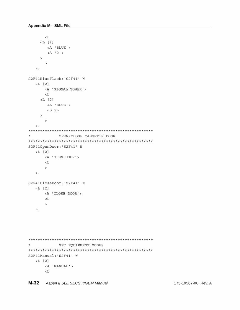
Appendix M—SML File
<L
<L [2]
<A 'BLUE'>
<A '0'>
>
>
>.
S2F41BlueFlash:'S2F41' W
<L [2]
<A 'SIGNAL_TOWER'>
<L
<L [2]
<A 'BLUE'>
<B 2>
>
>
>.
*****************************************************
* OPEN/CLOSE CASSETTE DOOR
*****************************************************
S2F41OpenDoor:'S2F41' W
<L [2]
<A 'OPEN DOOR'>
<L
>
>.
S2F41CloseDoor:'S2F41' W
<L [2]
<A 'CLOSE DOOR'>
<L
>
>.
*****************************************************
* SET EQUIPMENT MODES
*****************************************************
S2F41Manual:'S2F41' W
<L [2]
<A 'MANUAL'>
<L
M-32 Aspen II SLE SECS II/GEM Manual 175-19567-00, Rev. A

Appendix M—SML File
>
>.
S2F41SemiAuto:'S2F41' W
<L [2]
<A 'SEMI-AUTO'>
<L
>
>.
S2F41FullAuto:'S2F41' W
<L [2]
<A 'FULL-AUTO'>
<L
>
>.
*****************************************************
* SKIP EMPTY SLOTS YES/NO
*****************************************************
S2F41SkipEmpty:'S2F41' W
<L [2]
<A 'SKIP EMPTY'>
<L
>
>.
S2F41NoEmptySlot:'S2F41' W
<L [2]
<A 'NO EMPTY SLOT'>
<L
>
>.
S2F41OPERATOR:'S2F41' W
<L [2]
<A 'OPERATOR'>
<L [2]
<A 'ID'>
<A 'crb1'>
>
>.
S2F41BuzzerOn:'S2F41' W
<L [2]
<A 'BUZZER ON'>
<L
175-19567-00, Rev. A Aspen II SLE SECS II/GEM Manual M-33

Appendix M—SML File
>
>.
S2F41BuzzerOff:'S2F41' W
<L [2]
<A 'BUZZER OFF'>
<L
>
>.
S2F41LeakTest:'S2F41' W
<L [2]
<A 'LEAK TEST'>
<L
>
>.
S2F41EngineerMode:'S2F41' W
<L [2]
<A 'ENGINEER-MODE'>
<L
>
>.
S2F41SL1:'S2F41' W
<L [2]
<A 'SELECTION'>
<L
<L [2]
<A 'KEY'>
<U2 1>
>
>
>.
S2F41SL2:'S2F41' W
<L [2]
<A 'SELECTION'>
<L
<L [2]
<A 'KEY'>
<U2 2>
>
>
>.
M-34 Aspen II SLE SECS II/GEM Manual 175-19567-00, Rev. A

Appendix M—SML File
S2F41SL3:'S2F41' W
<L [2]
<A 'SELECTION'>
<L
<L [2]
<A 'KEY'>
<U2 3>
>
>
>.
S2F41SL4:'S2F41' W
<L [2]
<A 'SELECTION'>
<L
<L [2]
<A 'KEY'>
<U2 4>
>
>
>.
S2F41SL5:'S2F41' W
<L [2]
<A 'SELECTION'>
<L
<L [2]
<A 'KEY'>
<U2 5>
>
>
>.
S2F41SL6:'S2F41' W
<L [2]
<A 'SELECTION'>
<L
<L [2]
<A 'KEY'>
<U2 6>
>
>
>.
*****************************************************
* SMIF LOADER COMMANDS
*****************************************************
175-19567-00, Rev. A Aspen II SLE SECS II/GEM Manual M-35

Appendix M—SML File
S2F41UnloadCassesL:'S2F41' W
<L [2]
<A 'UNLOAD CASSETTES'>
<L
<A 'PORT'>
<A '1'> * 1= LEFT, 2=RIGHT, 3=BOTH
>
>.
S2F41UnloadCassesR:'S2F41' W
<L [2]
<A 'UNLOAD CASSETTES'>
<L
<A 'PORT'>
<B 2> * 1= LEFT, 2=RIGHT, 3=BOTH
>
>.
S2F41UnloadCassesB:'S2F41' W
<L [2]
<A 'UNLOAD CASSETTES'>
<L
<A 'PORT'>
<B 3> * 1= LEFT, 2=RIGHT, 3=BOTH
>
>.
S2F41LockLeftPod:'S2F41' W
<L
<A 'LOCK POD'>
<L
<L
<A 'PORT'>
<B 1> * 1= LEFT, 2=RIGHT, 3=BOTH
>
>
>.
S2F41LockRightPod:'S2F41' W
<L
<A 'LOCK POD'>
<L
<L
<A 'PORT'>
<B 2> * 1= LEFT, 2=RIGHT, 3=BOTH
>
M-36 Aspen II SLE SECS II/GEM Manual 175-19567-00, Rev. A
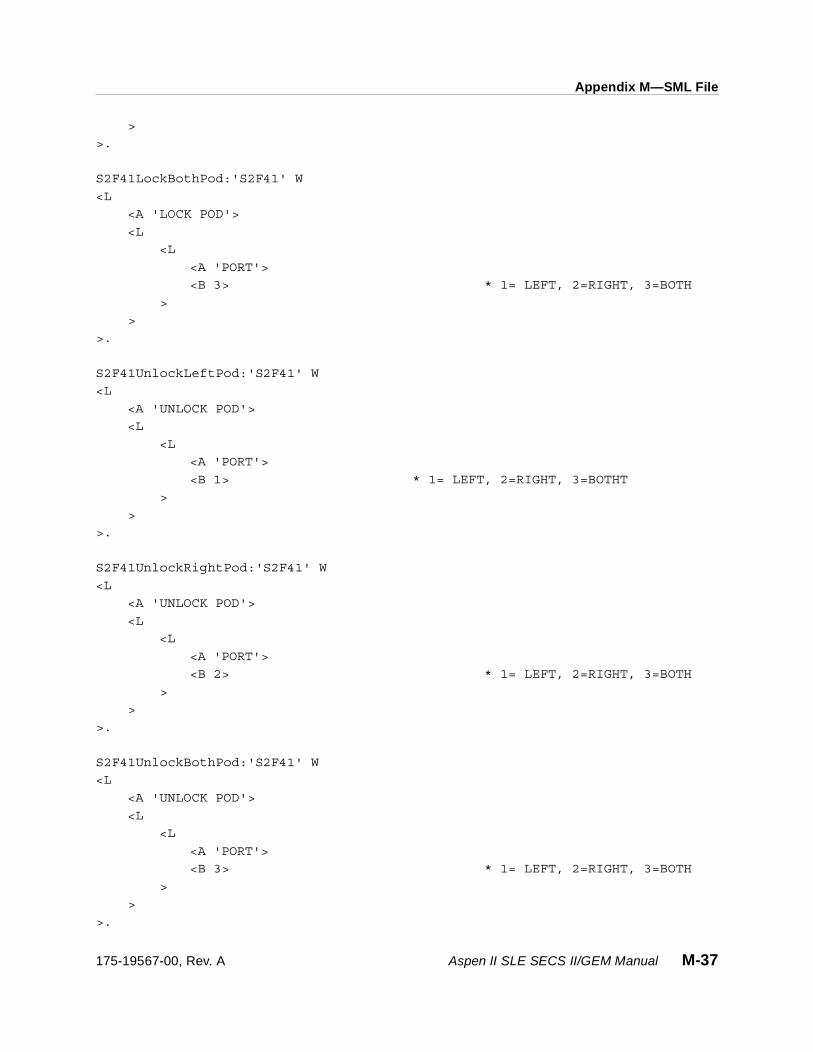
Appendix M—SML File
>
>.
S2F41LockBothPod:'S2F41' W
<L
<A 'LOCK POD'>
<L
<L
<A 'PORT'>
<B 3> * 1= LEFT, 2=RIGHT, 3=BOTH
>
>
>.
S2F41UnlockLeftPod:'S2F41' W
<L
<A 'UNLOCK POD'>
<L
<L
<A 'PORT'>
<B 1> * 1= LEFT, 2=RIGHT, 3=BOTHT
>
>
>.
S2F41UnlockRightPod:'S2F41' W
<L
<A 'UNLOCK POD'>
<L
<L
<A 'PORT'>
<B 2> * 1= LEFT, 2=RIGHT, 3=BOTH
>
>
>.
S2F41UnlockBothPod:'S2F41' W
<L
<A 'UNLOCK POD'>
<L
<L
<A 'PORT'>
<B 3> * 1= LEFT, 2=RIGHT, 3=BOTH
>
>
>.
175-19567-00, Rev. A Aspen II SLE SECS II/GEM Manual M-37

Appendix M—SML File
S2F41LoadCassLeft:'S2F41' W
<L
<A 'LOAD CASSETTE'>
<L
<L
<A 'PORT'>
<B 1> * 1= LEFT, 2=RIGHT, 3=BOTH
>
>
>.
S2F41LoadCassRight:'S2F41' W
<L
<A 'LOAD CASSETTE'>
<L
<L
<A 'PORT'>
<B 2> * 1= LEFT, 2=RIGHT, 3=BOTH
>
>
>.
S2F41LoadCassBoth:'S2F41' W
<L
<A 'LOAD CASSETTE'>
<L
<L
<A 'PORT'>
<B 3> * 1= LEFT, 2=RIGHT, 3=BOTH
>
>
>.
S2F41UnloadCassLeft:'S2F41' W
<L
<A 'UNLOAD CASSETTE'>
<L
<L
<A 'PORT'>
<B 1> * 1= LEFT, 2=RIGHT, 3=BOTH
>
>
>.
S2F41UnloadCassRight:'S2F41' W
M-38 Aspen II SLE SECS II/GEM Manual 175-19567-00, Rev. A
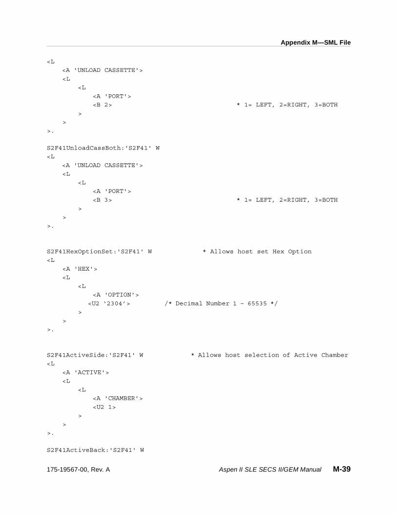
Appendix M—SML File
<L
<A 'UNLOAD CASSETTE'>
<L
<L
<A 'PORT'>
<B 2> * 1= LEFT, 2=RIGHT, 3=BOTH
>
>
>.
S2F41UnloadCassBoth:'S2F41' W
<L
<A 'UNLOAD CASSETTE'>
<L
<L
<A 'PORT'>
<B 3> * 1= LEFT, 2=RIGHT, 3=BOTH
>
>
>.
S2F41HexOptionSet:'S2F41' W * Allows host set Hex Option
<L
<A 'HEX'>
<L
<L
<A 'OPTION'>
<U2 ‘2304’> /* Decimal Number 1 – 65535 */
>
>
>.
S2F41ActiveSide:'S2F41' W * Allows host selection of Active Chamber
<L
<A 'ACTIVE'>
<L
<L
<A 'CHAMBER'>
<U2 1>
>
>
>.
S2F41ActiveBack:'S2F41' W
175-19567-00, Rev. A Aspen II SLE SECS II/GEM Manual M-39

Appendix M—SML File
<L
<A 'ACTIVE'>
<L
<L
<A 'CHAMBER'>
<U2 2>
>
>
>.
/* First binary is wafer 1 and last is Max Wafer 25 or 26*/
S2F41WaferMapLeft:'S2F41' W * Allows host to send wafer map
<L
<A 'SLOT MAP'>
<L
<L
<A 'PORT 1'>
<B ’01 01 01 01 01 00 00 00 01 01 01 01 01 etc to Max Waf # >
>
>
>.
S2F41WaferMapRight:'S2F41' W
<L
<A 'SLOT MAP'>
<L
<L
<A 'PORT 2'>
< B ’01 01 01 01 01 00 00 00 01 01 01 01 01 etc to Max Waf # >
>
>
>.
/* Send S2F41 Active Chamber First to select which chamber to reset Rf hours.*/
S2F41RESETRFHOURS:'S2F41' W * Allows host to reset CN page Rf Hours
<L
<A 'RESET'>
<L
<L
M-40 Aspen II SLE SECS II/GEM Manual 175-19567-00, Rev. A

Appendix M—SML File
<A 'RF HOURS'>
<I2 ’0’ > * 0 - 500000
>
>
>.
S2F41RESETWAFERSPROCESSED:'S2F41' W
<L
<A 'RESET'>
<L
<L
<A 'WAFS PROC'>
<I2 ’0’ > *0 - 99999999
>
>
>.
S2F47:'S2F47' W
<L
>.
***************************************************
* Spooling Streams and Functions
***************************************************
S2F65SpoolOFF:'S2F65' W
<L
>.
S2F65SpoolON:'S2F65' W
<L [4]
<L [2]
<U1 3> *STRID Stream # = 3
<L
> * Zero list enable all Functions F11
>
<L [2]
<U1 4> *STRID Stream # = 4
<L
> * Zero list enable all Functions F1,F17
>
<L [2]
<U1 6> *STRID Stream # = 6
<L
> * Zero list enable all Functions F1,F3,F11,F13
>
175-19567-00, Rev. A Aspen II SLE SECS II/GEM Manual M-41

Appendix M—SML File
<L [2]
<U1 7> *STRID Stream # = 7
<L
> * Zero list enable all Functions F7
>
>.
S2F65SpoolONBad:'S2F65' W
<L [2]
<L [2]
<U1 2> *STRID Stream # = 1
<L
> * Zero list enables all Functions
> * There is no Stream #1 Spooling
<L [2]
<U1 3> *STRID Stream # = 3
<L [2]
<U1 1> *There is no Stream #3 Spooling
<U1 2> *for F1, F2
>
>
>.
***************************************************
* Variable Limits Attributes
***************************************************
S2F85:'S2F85' W
<L
>.
S2F87DefineVarLimAttU:'S2F87' W
<L [2]
<U2 1> * DATAID = 1
<L
> * Zero length make undefined
>.
S2F87DefineVarLimAttDBad:'S2F87' W
<L [2]
<U2 1> * DATAID = 1, Only setting 2
VID's
<L [2]
<L [2]
<U2 11>/* VID #11 RF Power 1st chamber, 2 VID Limits
Set
<L [2]
M-42 Aspen II SLE SECS II/GEM Manual 175-19567-00, Rev. A

Appendix M—SML File
<L [2]
<B 0> * Limit ID #0
<L [2]
<I2 100> * RF Power upper limit
<I2 50> * RF Power lower limit
>
>
<L [2]
<B 1> * Limit ID #1
<L [2]
<I2 200> * RF Power upper limit
<I2 50> * RF Power lower limit
>
>
>
>
<L [2]
<U2 13> /* VID #13 Process Pressure, 1 VID Limits Set
<L [1]
<L [2]
<B 0> * Limit ID #0
<L [2]
<F4 10.00>/*Process Press upper
limit
<F4 0.50>/*Process Press lower
limit
>
>
>
>
>
>.
S2F87DefineVarLimAttDOK:'S2F87' W
<L [2]
<U2 1> * DATAID = 1, Only setting 2 VID's
<L [2]
<L [2]
<U2 11> /*VID #11 RF Pwr 1st cham, 2 VID Limits Set-
tings
<L [2]
<L [2]
<B 1> * Limit ID #1
<L [2]
<I2 100> * RF Power upper limit
<I2 50> * RF Power lower limit
175-19567-00, Rev. A Aspen II SLE SECS II/GEM Manual M-43
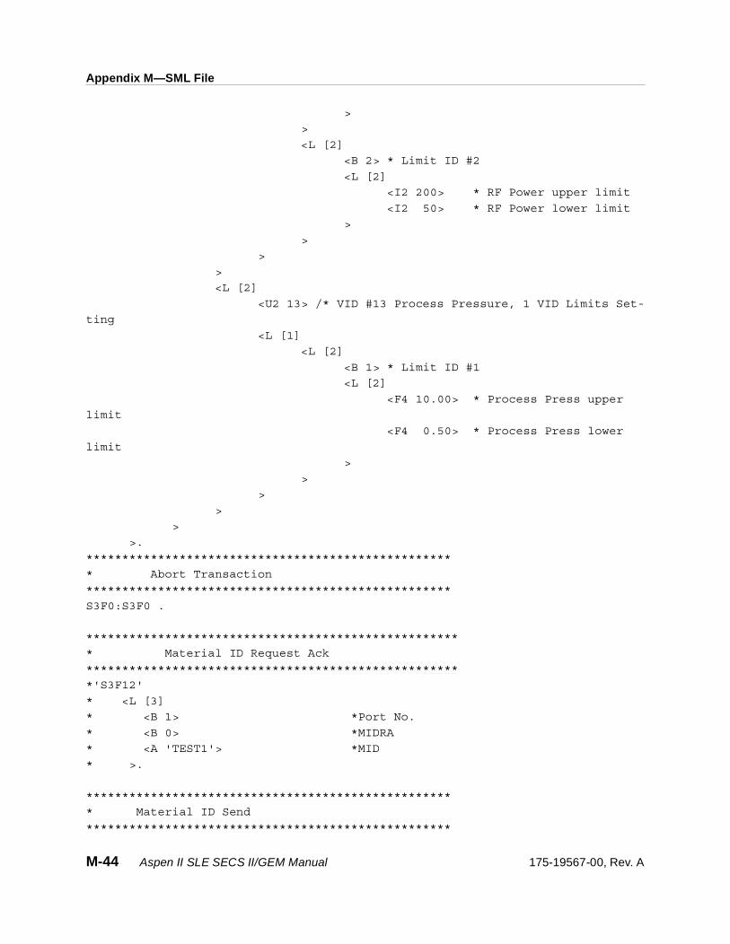
Appendix M—SML File
>
>
<L [2]
<B 2> * Limit ID #2
<L [2]
<I2 200> * RF Power upper limit
<I2 50> * RF Power lower limit
>
>
>
>
<L [2]
<U2 13> /* VID #13 Process Pressure, 1 VID Limits Set-
ting
<L [1]
<L [2]
<B 1> * Limit ID #1
<L [2]
<F4 10.00> * Process Press upper
limit
<F4 0.50> * Process Press lower
limit
>
>
>
>
>
>.
***************************************************
* Abort Transaction
***************************************************
S3F0:S3F0 .
****************************************************
* Material ID Request Ack
****************************************************
*'S3F12'
* <L [3]
* <B 1> *Port No.
* <B 0> *MIDRA
* <A 'TEST1'> *MID
* >.
***************************************************
* Material ID Send
***************************************************
M-44 Aspen II SLE SECS II/GEM Manual 175-19567-00, Rev. A

Appendix M—SML File
S3F13Mid1:'S3F13' W
<L [2]
<B 1> *Port No.
<A 'CA0001-00'> *MID
>.
S3F13Mid2:'S3F13' W
<L [2]
<B 2> *Port No.
<A 'CA0002-00'> *MID
>.
S3F13MID3:'S3F13' W
<L [2]
<B 1> *Port No.
<A 'CA0003-00'> *MID
>.
S3F13MID4:'S3F13' W
<L [2]
<B 2> *Port No.
<A 'CA0004-00'> *MID
>.
***************************************************
* Cassette ID Send
***************************************************
S3F13Cid1:'S3F13' W
<L [2]
<B 3> *Port No.
<A 'CID-0000001'> *CID
>.
S3F13Cid2:'S3F13' W
<L [2]
<B 4> *Port No.
<A 'CID-0000002'> *CID
>.
S3F13Cid3:'S3F13' W
<L [2]
<B 3> *Port No.
<A 'CID-0000003'> *CID
>.
175-19567-00, Rev. A Aspen II SLE SECS II/GEM Manual M-45

Appendix M—SML File
S3F13Cid4:'S3F13' W
<L [2]
<B 4> *Port No.
<A 'CID-0000004'> *CID
>.
***************************************************
* Abort Transaction
***************************************************
S4F0:S4F0 .
***************************************************
* Ready to Send Material (RSN)
***************************************************
S4F1RdySndMarl1:'S4F1' W
<L [2]
<B 1> * Port Number Left
<A 'crb1'>
>.
S4F1RdySndMarl2:'S4F1' W
<L [2]
<B 1> * Port Number Right
<A 'crb2'>
>.
'S4F66'
<B 0>.
***************************************************
* Abort Transaction
***************************************************
S5F0:S5F0 .
*************************************************
* Alarm Report Send
*************************************************
'S5F2'
<B 0>.
********************************************
* Disable Alarm Send
********************************************
S5F3DisableAlarm:'S5F3' W
<L [2]
<B 00> *ALED
M-46 Aspen II SLE SECS II/GEM Manual 175-19567-00, Rev. A

Appendix M—SML File
<U2 0> *ALID
>.
********************************************
* Enable Alarm Send
********************************************
S5F3EnableAlarm:'S5F3' W
<L [2]
<B 80> *ALED
<U2 0> *ALID
>.
********************************************
* List All Alarm Request
********************************************
S5F5All:'S5F5' W
<U2>.
********************************************
* List Alarm Request 2
********************************************
S5F5Alarm123:'S5F5' W
<U2 1 2 3>.
********************************************
* List Enable Alarm Request
********************************************
S5F7:'S5F7' W.
********************************************
* Alarm notification Send
********************************************
'S5F74'
<B 0>.
***************************************************
* Abort Transaction
***************************************************
S6F0:S6F0 .
*********************************************
* Trace Data Send
*********************************************
'S6F2'
<B 0>.
175-19567-00, Rev. A Aspen II SLE SECS II/GEM Manual M-47

Appendix M—SML File
*********************************************
* Discrete Variable Data Send
*********************************************
'S6F4'
<B 0>.
**********************************************
* Multi-block Data Send Inquire
**********************************************
'S6F6'
<B 0>.
***********************************************
* Formatted Variable Send
***********************************************
'S6F10'
<B 0>.
***********************************************
* Event Report Send
***********************************************
'S6F12'
<B 0>.
*************************************************
* Annotated Event Report Send
*************************************************
'S6F14'
<B 0>.
*************************************************
* Event Report Request
*************************************************
S6F15Ceid6:'S6F15' W
<U2 6>. *CEID
********************************************
* Annotated Event Report Request
********************************************
S6F17Ceid6:'S6F17' W
<U2 6>. *CEID
*******************************************
* Individual Report request
*******************************************
M-48 Aspen II SLE SECS II/GEM Manual 175-19567-00, Rev. A
Appendix M—SML File
S6F19Rpid2:'S6F19' W
<U2 2>. *RPTID
***********************************************
* Annotated Individual Report request
***********************************************
S6F21Rpid3:'S6F21' W
<U2 3>. *RPTID
***************************************************
* Request Spooled Data (RSD)
***************************************************
S6F65ReqSpooledData:'S6F65' W
<U1 0>. *RSDC Request Spooled Data Code 0 = Send
S6F65PurgeSpooledData:'S6F65' W
<U1 1>. *RSDC Request Spooled Data Code 1 = Purge
***************************************************
* Abort Transaction
***************************************************
S7F0:S7F0 .
************************************************
* Process Program Load Inquire
************************************************
S7F1Test1:'S7F1' W
<L [2]
<A 'TEST 1'> *PPID
<U2 333> *LENGTH
>.
S7F1Test2:'S7F1' W
<L [2]
<A 'TEST 2'> *PPID
<U2 333> *LENGTH
>.
S7F1Test3:'S7F1' W
<L [2]
<A 'TEST 3 '> *PPID
<U2 333> *LENGTH
>.
'S7F2'
175-19567-00, Rev. A Aspen II SLE SECS II/GEM Manual M-49
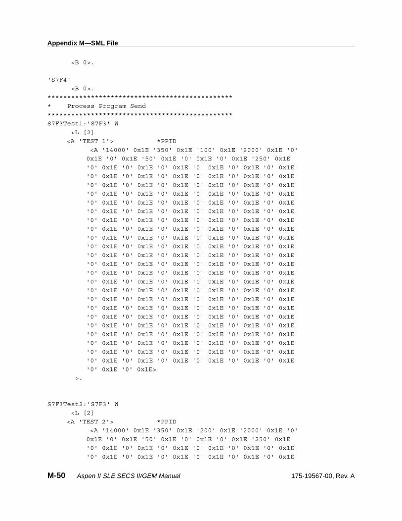
Appendix M—SML File
<B 0>.
'S7F4'
<B 0>.
***********************************************
* Process Program Send
***********************************************
S7F3Test1:'S7F3' W
<L [2]
<A 'TEST 1'> *PPID
<A '14000' 0x1E '350' 0x1E '100' 0x1E '2000' 0x1E '0'
0x1E '0' 0x1E '50' 0x1E '0' 0x1E '0' 0x1E '250' 0x1E
'0' 0x1E '0' 0x1E '0' 0x1E '0' 0x1E '0' 0x1E '0' 0x1E
'0' 0x1E '0' 0x1E '0' 0x1E '0' 0x1E '0' 0x1E '0' 0x1E
'0' 0x1E '0' 0x1E '0' 0x1E '0' 0x1E '0' 0x1E '0' 0x1E
'0' 0x1E '0' 0x1E '0' 0x1E '0' 0x1E '0' 0x1E '0' 0x1E
'0' 0x1E '0' 0x1E '0' 0x1E '0' 0x1E '0' 0x1E '0' 0x1E
'0' 0x1E '0' 0x1E '0' 0x1E '0' 0x1E '0' 0x1E '0' 0x1E
'0' 0x1E '0' 0x1E '0' 0x1E '0' 0x1E '0' 0x1E '0' 0x1E
'0' 0x1E '0' 0x1E '0' 0x1E '0' 0x1E '0' 0x1E '0' 0x1E
'0' 0x1E '0' 0x1E '0' 0x1E '0' 0x1E '0' 0x1E '0' 0x1E
'0' 0x1E '0' 0x1E '0' 0x1E '0' 0x1E '0' 0x1E '0' 0x1E
'0' 0x1E '0' 0x1E '0' 0x1E '0' 0x1E '0' 0x1E '0' 0x1E
'0' 0x1E '0' 0x1E '0' 0x1E '0' 0x1E '0' 0x1E '0' 0x1E
'0' 0x1E '0' 0x1E '0' 0x1E '0' 0x1E '0' 0x1E '0' 0x1E
'0' 0x1E '0' 0x1E '0' 0x1E '0' 0x1E '0' 0x1E '0' 0x1E
'0' 0x1E '0' 0x1E '0' 0x1E '0' 0x1E '0' 0x1E '0' 0x1E
'0' 0x1E '0' 0x1E '0' 0x1E '0' 0x1E '0' 0x1E '0' 0x1E
'0' 0x1E '0' 0x1E '0' 0x1E '0' 0x1E '0' 0x1E '0' 0x1E
'0' 0x1E '0' 0x1E '0' 0x1E '0' 0x1E '0' 0x1E '0' 0x1E
'0' 0x1E '0' 0x1E '0' 0x1E '0' 0x1E '0' 0x1E '0' 0x1E
'0' 0x1E '0' 0x1E '0' 0x1E '0' 0x1E '0' 0x1E '0' 0x1E
'0' 0x1E '0' 0x1E '0' 0x1E '0' 0x1E '0' 0x1E '0' 0x1E
'0' 0x1E '0' 0x1E '0' 0x1E '0' 0x1E '0' 0x1E '0' 0x1E
'0' 0x1E '0' 0x1E '0' 0x1E '0' 0x1E '0' 0x1E '0' 0x1E
'0' 0x1E '0' 0x1E>
>.
S7F3Test2:'S7F3' W
<L [2]
<A 'TEST 2'> *PPID
<A '14000' 0x1E '350' 0x1E '200' 0x1E '2000' 0x1E '0'
0x1E '0' 0x1E '50' 0x1E '0' 0x1E '0' 0x1E '250' 0x1E
'0' 0x1E '0' 0x1E '0' 0x1E '0' 0x1E '0' 0x1E '0' 0x1E
'0' 0x1E '0' 0x1E '0' 0x1E '0' 0x1E '0' 0x1E '0' 0x1E
M-50 Aspen II SLE SECS II/GEM Manual 175-19567-00, Rev. A

Appendix M—SML File
'0' 0x1E '0' 0x1E '0' 0x1E '0' 0x1E '0' 0x1E '0' 0x1E
'0' 0x1E '0' 0x1E '0' 0x1E '0' 0x1E '0' 0x1E '0' 0x1E
'0' 0x1E '0' 0x1E '0' 0x1E '0' 0x1E '0' 0x1E '0' 0x1E
'0' 0x1E '0' 0x1E '0' 0x1E '0' 0x1E '0' 0x1E '0' 0x1E
'0' 0x1E '0' 0x1E '0' 0x1E '0' 0x1E '0' 0x1E '0' 0x1E
'0' 0x1E '0' 0x1E '0' 0x1E '0' 0x1E '0' 0x1E '0' 0x1E
'0' 0x1E '0' 0x1E '0' 0x1E '0' 0x1E '0' 0x1E '0' 0x1E
'0' 0x1E '0' 0x1E '0' 0x1E '0' 0x1E '0' 0x1E '0' 0x1E
'0' 0x1E '0' 0x1E '0' 0x1E '0' 0x1E '0' 0x1E '0' 0x1E
'0' 0x1E '0' 0x1E '0' 0x1E '0' 0x1E '0' 0x1E '0' 0x1E
'0' 0x1E '0' 0x1E '0' 0x1E '0' 0x1E '0' 0x1E '0' 0x1E
'0' 0x1E '0' 0x1E '0' 0x1E '0' 0x1E '0' 0x1E '0' 0x1E
'0' 0x1E '0' 0x1E '0' 0x1E '0' 0x1E '0' 0x1E '0' 0x1E
'0' 0x1E '0' 0x1E '0' 0x1E '0' 0x1E '0' 0x1E '0' 0x1E
'0' 0x1E '0' 0x1E '0' 0x1E '0' 0x1E '0' 0x1E '0' 0x1E
'0' 0x1E '0' 0x1E '0' 0x1E '0' 0x1E '0' 0x1E '0' 0x1E
'0' 0x1E '0' 0x1E '0' 0x1E '0' 0x1E '0' 0x1E '0' 0x1E
'0' 0x1E '0' 0x1E '0' 0x1E '0' 0x1E '0' 0x1E '0' 0x1E
'0' 0x1E '0' 0x1E '0' 0x1E '0' 0x1E '0' 0x1E '0' 0x1E
'0' 0x1E '0' 0x1E '0' 0x1E '0' 0x1E '0' 0x1E '0' 0x1E
'0' 0x1E '0' 0x1E '0' 0x1E '0' 0x1E '0' 0x1E '0' 0x1E
'0' 0x1E '0' 0x1E>
>.
S7F3Test3:'S7F3' W
<L [2]
<A 'TEST 3 '> *PPID
<A '14000' 0x1E '350' 0x1E '300' 0x1E '2000' 0x1E '0'
0x1E '0' 0x1E '50' 0x1E '0' 0x1E '0' 0x1E '250' 0x1E
'0' 0x1E '0' 0x1E '0' 0x1E '0' 0x1E '0' 0x1E '0' 0x1E
'0' 0x1E '0' 0x1E '0' 0x1E '0' 0x1E '0' 0x1E '0' 0x1E
'0' 0x1E '0' 0x1E '0' 0x1E '0' 0x1E '0' 0x1E '0' 0x1E
'0' 0x1E '0' 0x1E '0' 0x1E '0' 0x1E '0' 0x1E '0' 0x1E
'0' 0x1E '0' 0x1E '0' 0x1E '0' 0x1E '0' 0x1E '0' 0x1E
'0' 0x1E '0' 0x1E '0' 0x1E '0' 0x1E '0' 0x1E '0' 0x1E
'0' 0x1E '0' 0x1E '0' 0x1E '0' 0x1E '0' 0x1E '0' 0x1E
'0' 0x1E '0' 0x1E '0' 0x1E '0' 0x1E '0' 0x1E '0' 0x1E
'0' 0x1E '0' 0x1E '0' 0x1E '0' 0x1E '0' 0x1E '0' 0x1E
'0' 0x1E '0' 0x1E '0' 0x1E '0' 0x1E '0' 0x1E '0' 0x1E
'0' 0x1E '0' 0x1E '0' 0x1E '0' 0x1E '0' 0x1E '0' 0x1E
'0' 0x1E '0' 0x1E '0' 0x1E '0' 0x1E '0' 0x1E '0' 0x1E
'0' 0x1E '0' 0x1E '0' 0x1E '0' 0x1E '0' 0x1E '0' 0x1E
'0' 0x1E '0' 0x1E '0' 0x1E '0' 0x1E '0' 0x1E '0' 0x1E
'0' 0x1E '0' 0x1E '0' 0x1E '0' 0x1E '0' 0x1E '0' 0x1E
'0' 0x1E '0' 0x1E '0' 0x1E '0' 0x1E '0' 0x1E '0' 0x1E
175-19567-00, Rev. A Aspen II SLE SECS II/GEM Manual M-51
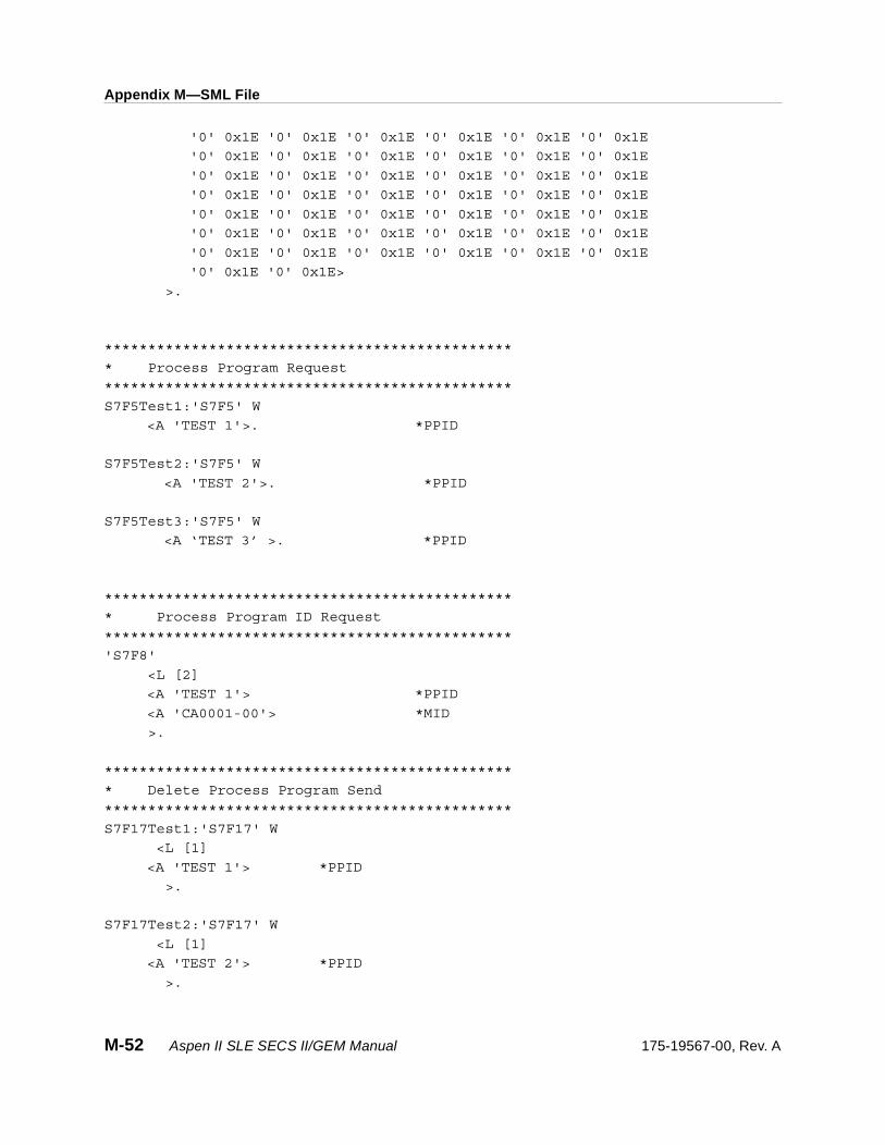
Appendix M—SML File
'0' 0x1E '0' 0x1E '0' 0x1E '0' 0x1E '0' 0x1E '0' 0x1E
'0' 0x1E '0' 0x1E '0' 0x1E '0' 0x1E '0' 0x1E '0' 0x1E
'0' 0x1E '0' 0x1E '0' 0x1E '0' 0x1E '0' 0x1E '0' 0x1E
'0' 0x1E '0' 0x1E '0' 0x1E '0' 0x1E '0' 0x1E '0' 0x1E
'0' 0x1E '0' 0x1E '0' 0x1E '0' 0x1E '0' 0x1E '0' 0x1E
'0' 0x1E '0' 0x1E '0' 0x1E '0' 0x1E '0' 0x1E '0' 0x1E
'0' 0x1E '0' 0x1E '0' 0x1E '0' 0x1E '0' 0x1E '0' 0x1E
'0' 0x1E '0' 0x1E>
>.
***********************************************
* Process Program Request
***********************************************
S7F5Test1:'S7F5' W
<A 'TEST 1'>. *PPID
S7F5Test2:'S7F5' W
<A 'TEST 2'>. *PPID
S7F5Test3:'S7F5' W
<A ‘TEST 3’ >. *PPID
***********************************************
* Process Program ID Request
***********************************************
'S7F8'
<L [2]
<A 'TEST 1'> *PPID
<A 'CA0001-00'> *MID
>.
***********************************************
* Delete Process Program Send
***********************************************
S7F17Test1:'S7F17' W
<L [1]
<A 'TEST 1'> *PPID
>.
S7F17Test2:'S7F17' W
<L [1]
<A 'TEST 2'> *PPID
>.
M-52 Aspen II SLE SECS II/GEM Manual 175-19567-00, Rev. A

Appendix M—SML File
S7F17Test3:'S7F17' W
<L [1]
<A 'TEST 3'> *PPID
>.
S7F17Test12:'S7F17' W
<L [2]
<A 'TEST 1'> *PPID
<A 'TEST 2'> *PPID
>.
S7F17Test13:'S7F17' W
<L []
<A 'TEST 1'> *PPID
<A 'TEST 3'> *PPID
>.
S7F17Test23:'S7F17' W
<L [2]
<A 'TEST 2'> *PPID
<A 'TEST 3'> *PPID
>.
***********************************************
* Current EPPD Request
***********************************************
S7F19:'S7F19' W.
***********************************************
* Formatted Process Program Send
***********************************************
S7F23Test1:'S7F23' W
<L [4]
<A 'TEST 1'>
<A 'ASPEN'>
<A '2.06C9'>
<L [11]
<L [2] *STEP ONE OF RECIPE (STEP 1 – 10 USE AS SHOWN)
<U2 0> *STEP 11 FOR ENDPOINT PARAMETERS
<L [15]
<U2 0> *RF TIME 1/10 SECONDS
<U2 80> *RF DELAY TIME 1/10 SECONDS
<I2 0> *RF POWER WATTS
<I4 3500> *PROCESS PRESSURE MTORR
175-19567-00, Rev. A Aspen II SLE SECS II/GEM Manual M-53

Appendix M—SML File
<U2 5000> *GAS 1 FLOW SETTING SCCM
<U2 100> *GAS 2 FLOW SETTING SCCM
<U2 0> *GAS 3 FLOW SETTING SCCM
<I2 250> *TEMPERATURE SETTING DEGREES CELSIUS
<U2 0> *ENDPOINT ENABLE ONE STEP ONLY 0=NO 1=REG 2=PS
<U2 0> *ATTRIBUTE GN/PIN/EP1/RFT%/SII 0=NNNNN 63=YYYYY
<I2 1> *NEXT STEP 0=NO 1=YES
<I2 0> *PRECOND RECIPE 0 - 99
<I2 0> *PRECOND FREQ 0 - 10
<U2 0> *GAS 4 FLOW SETTING SCCM
<I4 0> *RESERVED
>
>
<L [2] *STEP 2
<U2 0>
<L [15]
<U2 20>
<U2 80>
<I2 900>
<I4 1100>
<U2 800>
<U2 100>
<U2 0>
<I2 250>
<U2 0>
<U2 0>
<I2 1>
<I4 0>
<I4 0>
<I4 0>
<I4 0>
>
>
<L [2]
<U2 0>
<L [15]
<U2 0>
<U2 0>
<I2 0>
<I4 0>
<U2 0>
<U2 0>
<U2 0>
<I2 0>
<U2 0>
<U2 0>
M-54 Aspen II SLE SECS II/GEM Manual 175-19567-00, Rev. A

Appendix M—SML File
<I2 0>
<I4 0>
<I4 0>
<I4 0>
<I4 0>
>
>
<L [2]
<U2 0>
<L [15]
<U2 0>
<U2 0>
<I2 0>
<I4 0>
<U2 0>
<U2 0>
<U2 0>
<I2 0>
<U2 0>
<U2 0>
<I2 0>
<I4 0>
<I4 0>
<I4 0>
<I4 0>
>
>
<L [2]
<U2 0>
<L [15]
<U2 0>
<U2 0>
<I2 0>
<I4 0>
<U2 0>
<U2 0>
<U2 0>
<I2 0>
<U2 0>
<U2 0>
<I2 0>
<I4 0>
<I4 0>
<I4 0>
<I4 0>
>
175-19567-00, Rev. A Aspen II SLE SECS II/GEM Manual M-55
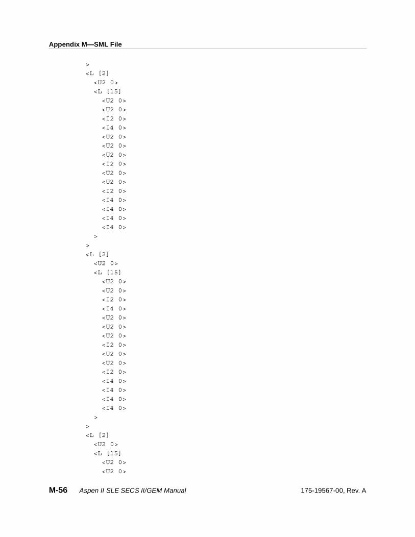
Appendix M—SML File
>
<L [2]
<U2 0>
<L [15]
<U2 0>
<U2 0>
<I2 0>
<I4 0>
<U2 0>
<U2 0>
<U2 0>
<I2 0>
<U2 0>
<U2 0>
<I2 0>
<I4 0>
<I4 0>
<I4 0>
<I4 0>
>
>
<L [2]
<U2 0>
<L [15]
<U2 0>
<U2 0>
<I2 0>
<I4 0>
<U2 0>
<U2 0>
<U2 0>
<I2 0>
<U2 0>
<U2 0>
<I2 0>
<I4 0>
<I4 0>
<I4 0>
<I4 0>
>
>
<L [2]
<U2 0>
<L [15]
<U2 0>
<U2 0>
M-56 Aspen II SLE SECS II/GEM Manual 175-19567-00, Rev. A

Appendix M—SML File
<I2 0>
<I4 0>
<U2 0>
<U2 0>
<U2 0>
<I2 0>
<U2 0>
<U2 0>
<I2 0>
<I4 0>
<I4 0>
<I4 0>
<I4 0>
>
>
<L [2]
<U2 0>
<L [15]
<U2 0>
<U2 0>
<I2 0>
<I4 0>
<U2 0>
<U2 0>
<U2 0>
<I2 0>
<U2 0>
<U2 0>
<I2 0>
<I4 0>
<I4 0>
<I4 0>
<I4 0>
>
>
<L [2]
<U2 0>
<L [15]
<U2 0>
<U2 0>
<I2 0>
<I4 0>
<U2 0>
<U2 0>
<U2 0>
<I2 0>
175-19567-00, Rev. A Aspen II SLE SECS II/GEM Manual M-57

Appendix M—SML File
<U2 0>
<U2 0>
<I2 0>
<I4 0>
<I4 0>
<I4 0>
<I4 0>
>
>
<L [2] *STEP 11 FOR ENDPOINT PARAMETERS
<U2 0>
<L [15]
<U2 2> *ENDPOINT TYPE 0=NONE 1=REGULAR 2=PEAK SEARCH
<U2 0> *UPSLOPE THRESHOLD 1-200 COUNTS, 0=DISABLED
<I2 0> *RESERVED
<I4 100> *MINIMUM CHANGE 1 – 1000 COUNTS, 0 = DISABLED
<U2 1> *SCALE/SENSITIVITY 1 – 8, 9 =DATA COLLECT, 0 = DIS-
ABLED
<U2 1> *CHANNEL SELECT 0 = A, 1 = B, 2 = A&B
<U2 10> *START DELAY TIME 0 TO 30 SECONDS
<I2 50> *FINAL THRESHOLD 1 – 99%, 0 = DISABLED
<U2 0> *PEAK DEBOUNCE 1 – 60 COUNTS 0 = DISABLED
<U2 200> *MINIMUM TIME 0 - <Max Step Time IN DECI-SECONDS
<I2 0> *DOWNSLOPE THRESHOLD 1 –200 COUNTS, 0 = DISABLED
<I4 0> *FLAT PEAK DEVIATION 1 – 30 COUNTS, 0 = DISABLED
<I4 0> *FLAT PEAK COUNTS 1 – 60, 0 = DISABLED
<I4 0> *RESERVED
<I4 0> *RESERVED
>
>
>.
'S7F24' <B 0>.
***********************************************
* Invalid Formatted Process Program Send
***********************************************
S7F23Test1Invalid:'S7F23' W
<L [4]
<A 'TEST 1'>
<A 'ASPEN'>
<A '2.06C9'>
<L [10]
<L [2]
<U2 0>
<L [15]
M-58 Aspen II SLE SECS II/GEM Manual 175-19567-00, Rev. A
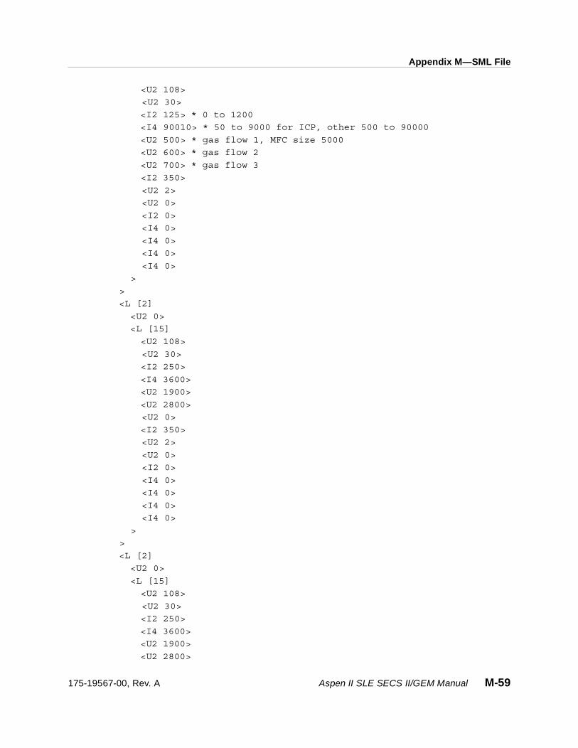
Appendix M—SML File
<U2 108>
<U2 30>
<I2 125> * 0 to 1200
<I4 90010> * 50 to 9000 for ICP, other 500 to 90000
<U2 500> * gas flow 1, MFC size 5000
<U2 600> * gas flow 2
<U2 700> * gas flow 3
<I2 350>
<U2 2>
<U2 0>
<I2 0>
<I4 0>
<I4 0>
<I4 0>
<I4 0>
>
>
<L [2]
<U2 0>
<L [15]
<U2 108>
<U2 30>
<I2 250>
<I4 3600>
<U2 1900>
<U2 2800>
<U2 0>
<I2 350>
<U2 2>
<U2 0>
<I2 0>
<I4 0>
<I4 0>
<I4 0>
<I4 0>
>
>
<L [2]
<U2 0>
<L [15]
<U2 108>
<U2 30>
<I2 250>
<I4 3600>
<U2 1900>
<U2 2800>
175-19567-00, Rev. A Aspen II SLE SECS II/GEM Manual M-59

Appendix M—SML File
<U2 0>
<I2 350>
<U2 2>
<U2 0>
<I2 0>
<I4 0>
<I4 0>
<I4 0>
<I4 0>
>
>
<L [2]
<U2 0>
<L [15]
<U2 108>
<U2 30>
<I2 250>
<I4 3600>
<U2 1900>
<U2 2800>
<U2 0>
<I2 350>
<U2 2>
<U2 0>
<I2 0>
<I4 0>
<I4 0>
<I4 0>
<I4 0>
>
>
<L [2]
<U2 0>
<L [15]
<U2 108>
<U2 30>
<I2 250>
<I4 3600>
<U2 1900>
<U2 2800>
<U2 0>
<I2 350>
<U2 2>
<U2 0>
<I2 0>
<I4 0>
M-60 Aspen II SLE SECS II/GEM Manual 175-19567-00, Rev. A

Appendix M—SML File
<I4 0>
<I4 0>
<I4 0>
>
>
<L [2]
<U2 0>
<L [15]
<U2 108>
<U2 30>
<I2 250>
<I4 3600>
<U2 1900>
<U2 2800>
<U2 0>
<I2 350>
<U2 2>
<U2 0>
<I2 0>
<I4 0>
<I4 0>
<I4 0>
<I4 0>
>
>
<L [2]
<U2 0>
<L [15]
<U2 108>
<U2 30>
<I2 250>
<I4 3600>
<U2 1900>
<U2 2800>
<U2 0>
<I2 350>
<U2 2>
<U2 0>
<I2 0>
<I4 0>
<I4 0>
<I4 0>
<I4 0>
>
>
<L [2]
175-19567-00, Rev. A Aspen II SLE SECS II/GEM Manual M-61
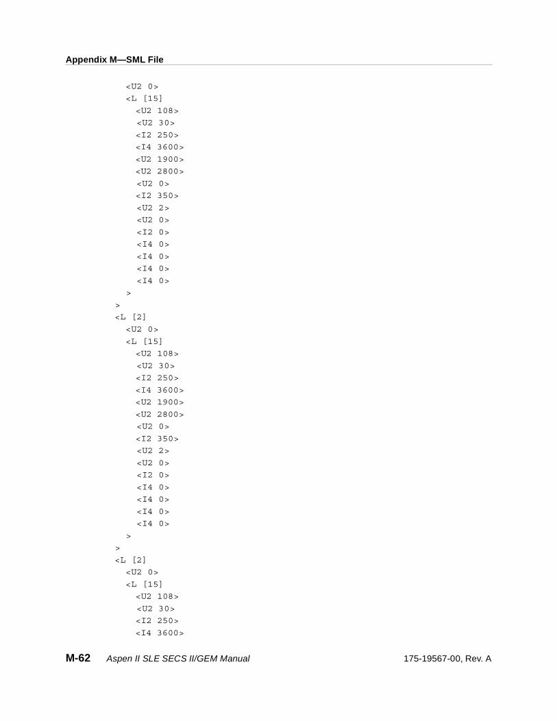
Appendix M—SML File
<U2 0>
<L [15]
<U2 108>
<U2 30>
<I2 250>
<I4 3600>
<U2 1900>
<U2 2800>
<U2 0>
<I2 350>
<U2 2>
<U2 0>
<I2 0>
<I4 0>
<I4 0>
<I4 0>
<I4 0>
>
>
<L [2]
<U2 0>
<L [15]
<U2 108>
<U2 30>
<I2 250>
<I4 3600>
<U2 1900>
<U2 2800>
<U2 0>
<I2 350>
<U2 2>
<U2 0>
<I2 0>
<I4 0>
<I4 0>
<I4 0>
<I4 0>
>
>
<L [2]
<U2 0>
<L [15]
<U2 108>
<U2 30>
<I2 250>
<I4 3600>
M-62 Aspen II SLE SECS II/GEM Manual 175-19567-00, Rev. A
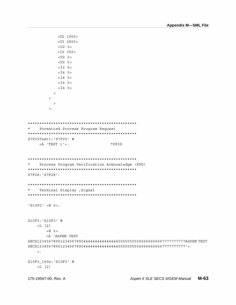
Appendix M—SML File
<U2 1900>
<U2 2800>
<U2 0>
<I2 350>
<U2 2>
<U2 0>
<I2 0>
<I4 0>
<I4 0>
<I4 0>
<I4 0>
>
>
>
>.
***********************************************
* Formatted Process Program Request
***********************************************
S7F25Test1:'S7F25' W
<A 'TEST 1'>. *PPID
***********************************************
* Process Program Verification Acknowledge (FPD)
***********************************************
S7F28:'S7F28'.
***********************************************
* Terminal Display ,Signal
***********************************************
'S10F2' <B 0>.
S10F3:'S10F3' W
<L [2]
<B 0>
<A 'ASPEN TEST
SECS1234567890123456789044444444444444455555555566666666667777777777ASPEN TEST
SECS1234567890123456789044444444444444455555555566666666667777777777'>
>.
S10F3_160x:'S10F3' W
<L [2]
175-19567-00, Rev. A Aspen II SLE SECS II/GEM Manual M-63

Appendix M—SML File
0'>
0'>
<B 0> *1 10 20 30 40 50
60 70 80 90 100 110 120
130 140 150 160
<A
'123456789a123456789b123456789c123456789d123456789e123456789f123456789g1234567
89hAASPEN TESTx
SECS1234567890123456789044444444444444455555555566666666667777777777ASPEN TEST
SECS1234567890123456789044444444444444455555555566666666667777777777'>
>.
S10F5Test1:'S10F5' W
<L [2]
<B 0>
<L [4]
<A
'1234567890223456789032345678904234567890523456789062345678907234567890823456789
<A 'this is test'>
<A ' this is test'>
<A '
this is test'>
>
>.
S10F5Test2:'S10F5' W
<L [2]
<B 0>
<L [19]
<A
'1234567890223456789032345678904234567890523456789062345678907234567890823456789
<A 'this is test2'>
<A 'this is test3'>
<A 'this is test4'>
<A 'this is test5'>
<A 'this is test6'>
<A 'this is test7'>
<A 'this is test8'>
<A 'this is test9'>
<A 'this is test10'>
<A 'this is test11'>
<A 'this is test12'>
<A 'this is test13'>
M-64 Aspen II SLE SECS II/GEM Manual 175-19567-00, Rev. A
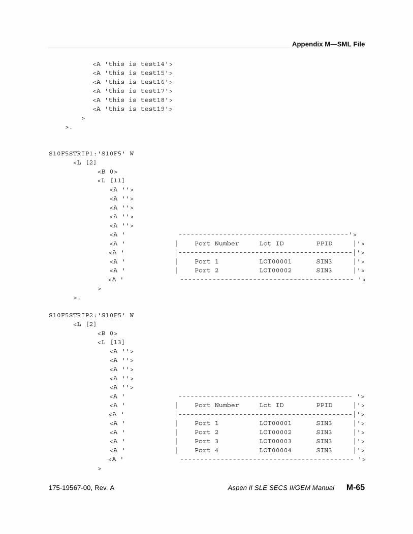
Appendix M—SML File
<A 'this is test14'>
<A 'this is test15'>
<A 'this is test16'>
<A 'this is test17'>
<A 'this is test18'>
<A 'this is test19'>
>
>.
S10F5STRIP1:'S10F5' W
<L [2]
<B 0>
<L [11]
<A ''>
<A ''>
<A ''>
<A ''>
<A ''>
<A ' ------------------------------------------'>
<A ' | Port Number Lot ID PPID |'>
<A ' |-------------------------------------------|'>
<A ' | Port 1 LOT00001 SIN3 |'>
<A ' | Port 2 LOT00002 SIN3 |'>
<A ' ------------------------------------------- '>
>
>.
S10F5STRIP2:'S10F5' W
<L [2]
<B 0>
<L [13]
<A ''>
<A ''>
<A ''>
<A ''>
<A ''>
<A ' ------------------------------------------- '>
<A ' | Port Number Lot ID PPID |'>
<A ' |-------------------------------------------|'>
<A ' | Port 1 LOT00001 SIN3 |'>
<A ' | Port 2 LOT00002 SIN3 |'>
<A ' | Port 3 LOT00003 SIN3 |'>
<A ' | Port 4 LOT00004 SIN3 |'>
<A ' ------------------------------------------- '>
>
175-19567-00, Rev. A Aspen II SLE SECS II/GEM Manual M-65
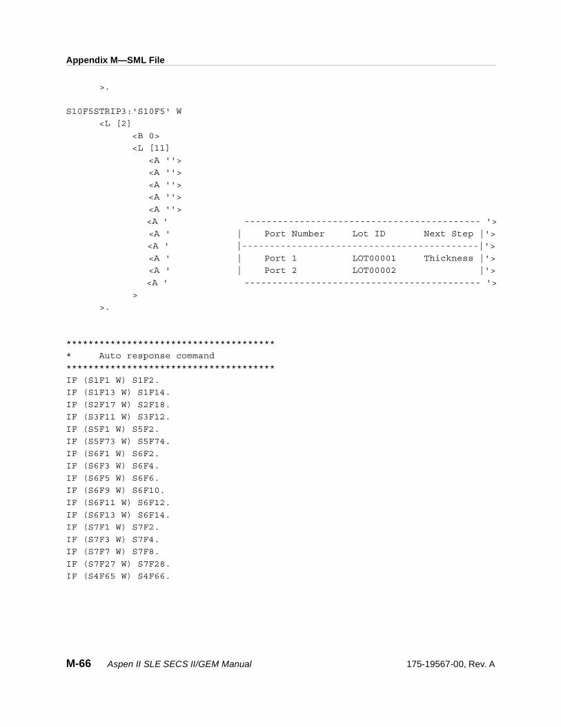
Appendix M—SML File
>.
S10F5STRIP3:'S10F5' W
<L [2]
<B 0>
<L [11]
<A ''>
<A ''>
<A ''>
<A ''>
<A ''>
<A ' ------------------------------------------- '>
<A ' | Port Number Lot ID Next Step |'>
<A ' |-------------------------------------------|'>
<A ' | Port 1 LOT00001 Thickness |'>
<A ' | Port 2 LOT00002 |'>
<A ' ------------------------------------------- '>
>
>.
**************************************
* Auto response command
**************************************
IF (S1F1 W) S1F2.
IF (S1F13 W) S1F14.
IF (S2F17 W) S2F18.
IF (S3F11 W) S3F12.
IF (S5F1 W) S5F2.
IF (S5F73 W) S5F74.
IF (S6F1 W) S6F2.
IF (S6F3 W) S6F4.
IF (S6F5 W) S6F6.
IF (S6F9 W) S6F10.
IF (S6F11 W) S6F12.
IF (S6F13 W) S6F14.
IF (S7F1 W) S7F2.
IF (S7F3 W) S7F4.
IF (S7F7 W) S7F8.
IF (S7F27 W) S7F28.
IF (S4F65 W) S4F66.
M-66 Aspen II SLE SECS II/GEM Manual 175-19567-00, Rev. A
Related Documents