GebhardtVentilatoren Radialventilator RZA Ausgabe 3 Centrifugal Fan RZA Issue 3 rotavent ®

Welcome message from author
This document is posted to help you gain knowledge. Please leave a comment to let me know what you think about it! Share it to your friends and learn new things together.
Transcript

1
GebhardtVentilatoren
Radialventilator RZAAusgabe 3
Centrifugal Fan RZAIssue 3
rotavent®
2
GebhardtVentilatoren Radialventilator mit LowSlip Einbaumotor Centrifugal Fan with integral motor
kompakte Compact Pioneering Spitzentechnologie Technology
Durch die Kombination zweier Spitzentechnologien - die Aero dynamik des rotavent, kombiniert mit ener-gie-optimierten Einbaumoto ren - hat Gebhardt eine Baureihe regelbarer Radialventilatoren mit Direktantrieb entwickelt, die Maß stäbe setzen in Wirtschaftlichkeit, Geräuschkomfort und Kompaktheit.Die VorteileHohe Systemwirkungsgrade auch bei Teillastbe-trieb durch Einsatz von Wirkungsgradoptimierten Komponenten: Ventilator, Motor und Regelung sind aufeinander abgestimmt.
- hohe Wirtschaftlichkeit- niedrige Energiekosten- niedriges Geräusch- kompakt und wartungsfrei- flexibel einsetzbar
MotorMotor
FrequenzumrichterFrequenzy inverter
VentilatorFan
nutzbare Strömungsenergieavailable volume flow
Verlustelosses
Energieeinsatz 100 %Input energy 100 %
ηF ηF · ηM ηF · ηM · ηV = ηfaS
Through the combination of two pioneering technolo-gies: the aerodynamics of the rotavent impeller combi-ned with energy efficient integral motors, Gebhardt has developed a series of controllable direct drive centrifu-gal fans setting new standards for economy and quiet operation.Your benefitsA highly efficient system through the use of energy optimised components: fans, motors and frequency inverters, operating together in harmony.
- high efficiency- low energy costs- low noise- compact and maintenance free fans- flexible in its operation
Das System The systemRZA rotavent
Wirtschaftlich, leise und kompakt Economic, quiet and compactRZA rotavent
3
Besc
hrei
bung
Desc
riptio
nZu
behö
rAc
cess
orie
sAu
ssch
reib
ung
Spec
ifica
tion
Tech
nisc
he D
aten
Tech
nica
l Dat
aTe
chno
logi
eTe
chno
logy
GebhardtVentilatoren Radialventilator mit LowSlip Einbaumotor Centrifugal Fan with integral motor
kompakte Compact Pioneering Spitzentechnologie Technology
Durch Metall-Klemmenkasten auf dem Motor-Achsrohr leicht zugänglich angeordnet.
Ihre Vorteile:- einfacher, schneller Anschluss- sicherer Betrieb
von 0 bis 100 % durch effiziente Frequenzumrichter.
Ihre Vorteile:- große Flexibilität- problemlose Anpassung an unterschiedlichste
Betriebsbedingungen- hohe Teillastwirkungsgrade
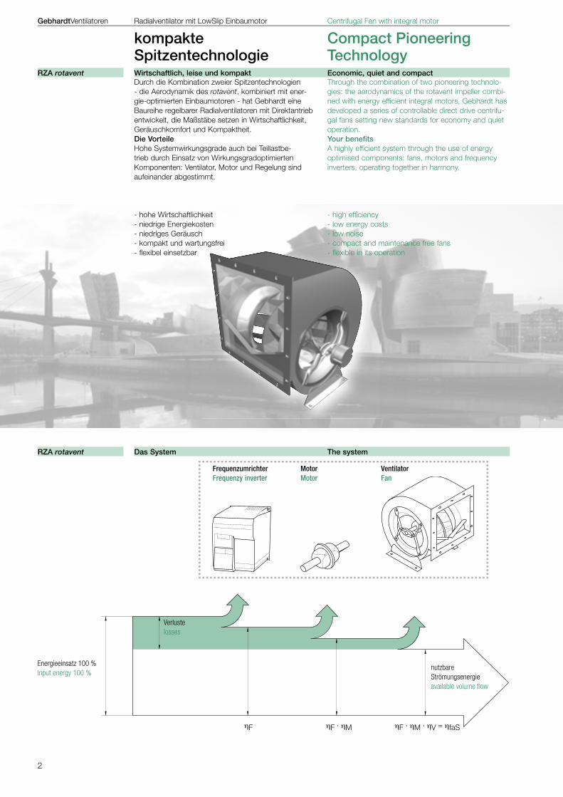
durch Direktantrieb mit eingebautem Gebhardt Außenläufermotor. Variable Stellungen durch umsetzbare Füße.
Ihre Vorteile:- kein sperriger Grundrahmen- kein Riemenverschleiß- keine Riementriebwartung- Gehäusestellung auch nachträglich in 90° Schritten
änderbar
entwickelt und optimiert für hohe Wirkungsgrade bei Frequenzumrichterbetrieb, mit eingebauten Kaltleiter - Temperaturfühlern und in aerodynamisch optimiertem Design.
Ihre Vorteile:- hohe Wirtschaftlichkeit- hoher Sicherheitsstandard- optimaler Motorschutz
sorgt für ruhigen Lauf.
Ihre Vorteile:- Übertragung von Schwingungen und Körperschall auf
Anlagenteile und Gebäude werden reduziert
Gebhardt hat eine Meßvorrichtung entwickelt, die es ermöglicht, den Volumenstrom des Ventilators in der Einströmdüse zu ermitteln.
Ihre Vorteile:- einfache Überwachung möglich- bedarfsgerechte Regelung- maximale Wirtschaftlichkeit
a metal terminal box on the hollow motor shaft provi-des easy access.
Your Benefits:- easier, faster connection- safer connection
from 0% to 100% through efficient frequency inverter.
Your Benefits:- varying performance- easily adjustable to different operating conditions- high efficiency
through direct drive and external rotor motor. Variable housing positions through interchangeable feet.
Your Benefits:- no bulky base framework- no belt wear- no belt maintenance- housing position adjustable 90° settings
Especially developed by Gebhardt for maximised ef-ficiency when controlled with a frequency inverter, with built-in PTC thermistor temperature probe within an aerodynamically optimised construction.
Your Benefits:- high efficiency- high safety standards- optimised motor protection
providing quiet operation.
Your Benefits:- the transmission of vibration and noise from the fan to
the construction housing is significantly reduced
Gebhardt has developed a measuring device that makes it possible to determine the volume flow rate through the fan inlet cones.
Your Benefits:- ease of commissioning- minimised operating costs through close control
Kompakt und wartungsfrei Compact and maintenance freeRZA rotavent
Einfacher und sicherer Anschluss Easier, Safer ConnectionRZA rotavent
Problemlose und wirtschaftliche Drehzahlregelung Easy and efficient speed controlRZA rotavent
Neue Motoren New motorsRZA rotavent
Schwingungsisolierte Motoraufhängung The motor is suspended through vibration isolationRZA rotavent
Volumenstrom Meßvorrichtung Volume flow measuring devicesRZA rotavent
4
ηmax
ϕopt
Frequenz
Sch
allp
egel Reduzierung
V .
±5%
±5%
�pt
GebhardtVentilatoren Radialventilator mit LowSlip Einbaumotor Centrifugal Fan with integral motor
kompakte Compact Pioneering Spitzentechnologie Technology
Über große Kennfeldbereiche arbeiten Gebhardt Ventilatoren besonders wirtschaftlich.Ihre Vorteile:- niedrige Betriebskosten- hohe Wirtschaftlichkeit
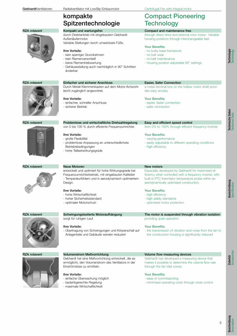
Geringe Strömungsgeschwindigkeiten an Ein- und Austritt des Ventilators durch große, freie Querschnitte ergeben zusammen mit dem günstigen Strömungsverhalten des Laufrades die beispielhafte Aerodynamik und Leistung des rotavent.Ihre Vorteile:- geringe Empfindlichkeit gegen Einbaustörungen- geringer Druckverlust bei freiem Ausblasen- kleines Bauvolumen bei großer Strömungsleistung
Hoher Geräuschkomfort durch die rotavent Vorteile, kombiniert mit optimierten Motoren und Frequenzumrichtern. Niedrige Schallpegel vor allem bei tiefen Frequenzen durch die optimierte Laufradgeometrie des rotavent mit schräggestellten Laufradschaufeln und gegenläufig schräger Zunge im Ausblas.Ihre Vorteile:- Maßnahmen zur Schalldämpfung sind oft unnötig
oder werden erheblich reduziert
Die Leistungsdaten der Ventilatoren werden auf Normprüfständen gemessen und entsprechen der Genauigkeitsklasse 2 nach DIN 24 166.Ihre Vorteile:- reproduzierbare und verläßliche Daten
Over a very wide performance range, i.e. Gebhardt fans are able to efficienctly cover large performance ranges.Your Benefits:- low running costs- high efficiency
Low turbulance velocity for both inlet and discharge due to the large free cross section and minimal flow restraint of the impeller, an example of aerodynamics and performance of the rotavent.Your Benefits:- negligible sensitivity to built in disturbances- smaller, yet greater energy performance
Reduction of high frequency noise levels is just one of the advantages of the rotavent, together with optimised motors and frequency inverters. Minimal sound levels due to low blade passing frequencies from the opti-mised impeller geometry of the rotavent. The impeller has obliquely inclined blades with trailing edges, and the throat plate is inclined opposingly.Your Benefits:- reduced size and costs of attenuation and silencers
The performance data of the fan will be measured through standardised testing and in accordance with precision class 2 DIN 24 166 and BS 848 1980 Class “B”.Your Benefits:- reproducible and reliable data
Optimierte Aerodynamik Optimal AerodynamicsRZA rotavent
Hohe Wirkungsgrade Highly EfficientRZA rotavent
Akustik AcousticsRZA rotavent
Verläßliche Daten Reliable DataRZA rotavent
5
Tech
nolo
gie
Tech
nolo
gy
[3]
[4]
[5] [6][7]
[8]
0
200
400
600
800
1000
1200
1400
0 5000 10000 15000 20000 25000 30000
�p f
a
Pa
m3/h
[1] RZA 11-0225-4D[2] RZA 11-0250-4D[3] RZA 11-0280-4D[4] RZA 11-0315-4D[5] RZA 11-0355-4D[6] RZA 11-0400-4D[7] RZA 11-0450-4D[8] RZA 11-0500-6D[9] RZA 11-0560-6D
V .
[9]
[2]
[1]
GebhardtVentilatoren Radialventilator mit LowSlip Einbaumotor Centrifugal Fan with integral motor
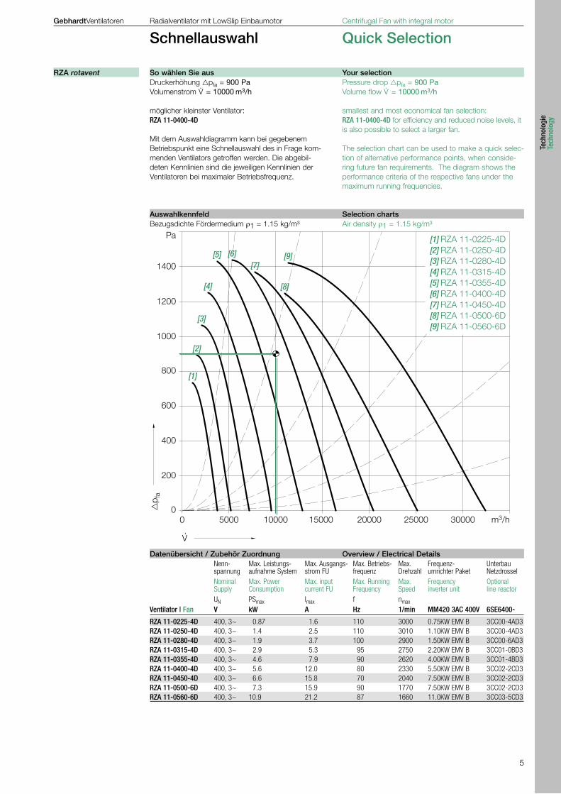
Schnellauswahl Quick Selection
Druckerhöhung pfa = 900 PaVolumenstrom V
. = 10000 m3/h
möglicher kleinster Ventilator:RZA 11-0400-4D
Mit dem Auswahldiagramm kann bei gegebenem Betriebspunkt eine Schnellauswahl des in Frage kom-menden Ventilators getroffen werden. Die abgebil-deten Kennlinien sind die jeweiligen Kennlinien der Ventilatoren bei maximaler Betriebsfrequenz.
Bezugsdichte Fördermedium ρ1 = 1.15 kg/m³
Nenn- Max. Leistungs- Max. Ausgangs- Max. Betriebs- Max. Frequenz- Unterbau spannung aufnahme System strom FU frequenz Drehzahl umrichter Paket Netzdrossel Nominal Max. Power Max. input Max. Running Max. Frequency Optional Supply Consumption current FU Frequency Speed inverter unit line reactor UN PSmax Imax f nmax Ventilator | Fan V kW A Hz 1/min MM420 3AC 400V 6SE6400-
RZA 11-0225-4D 400, 3~ 0.87 1.6 110 3000 0.75KW EMV B 3CC00-4AD3RZA 11-0250-4D 400, 3~ 1.4 2.5 110 3010 1.10KW EMV B 3CC00-4AD3RZA 11-0280-4D 400, 3~ 1.9 3.7 100 2900 1.50KW EMV B 3CC00-6AD3RZA 11-0315-4D 400, 3~ 2.9 5.3 95 2750 2.20KW EMV B 3CC01-0BD3RZA 11-0355-4D 400, 3~ 4.6 7.9 90 2620 4.00KW EMV B 3CC01-4BD3RZA 11-0400-4D 400, 3~ 5.6 12.0 80 2330 5.50KW EMV B 3CC02-2CD3RZA 11-0450-4D 400, 3~ 6.6 15.8 70 2040 7.50KW EMV B 3CC02-2CD3RZA 11-0500-6D 400, 3~ 7.3 15.9 90 1770 7.50KW EMV B 3CC02-2CD3RZA 11-0560-6D 400, 3~ 10.9 21.2 87 1660 11.0KW EMV B 3CC03-5CD3
Pressure drop pfa = 900 PaVolume flow V
. = 10000 m3/h
smallest and most economical fan selection:RZA 11-0400-4D for efficiency and reduced noise levels, it is also possible to select a larger fan.
The selection chart can be used to make a quick selec-tion of alternative performance points, when conside-ring future fan requirements. The diagram shows the performance criteria of the respective fans under the maximum running frequencies.
Air density ρ1 = 1.15 kg/m³
So wählen Sie aus Your selectionRZA rotavent
Auswahlkennfeld Selection charts
Datenübersicht / Zubehör Zuordnung Overview / Electrical Details
6
399
26212191
447
270220
26
2625
5
468
194
100
130
348322
10.5
3
48
3
22
286
2
x 1
00244
10
2
88
30 176
176
LG 0 LG 90 LG 180 LG 270 RD 0 RD 90 RD 180 RD 270
GebhardtVentilatoren Radialventilator mit LowSlip Einbaumotor Centrifugal Fan with integral motor
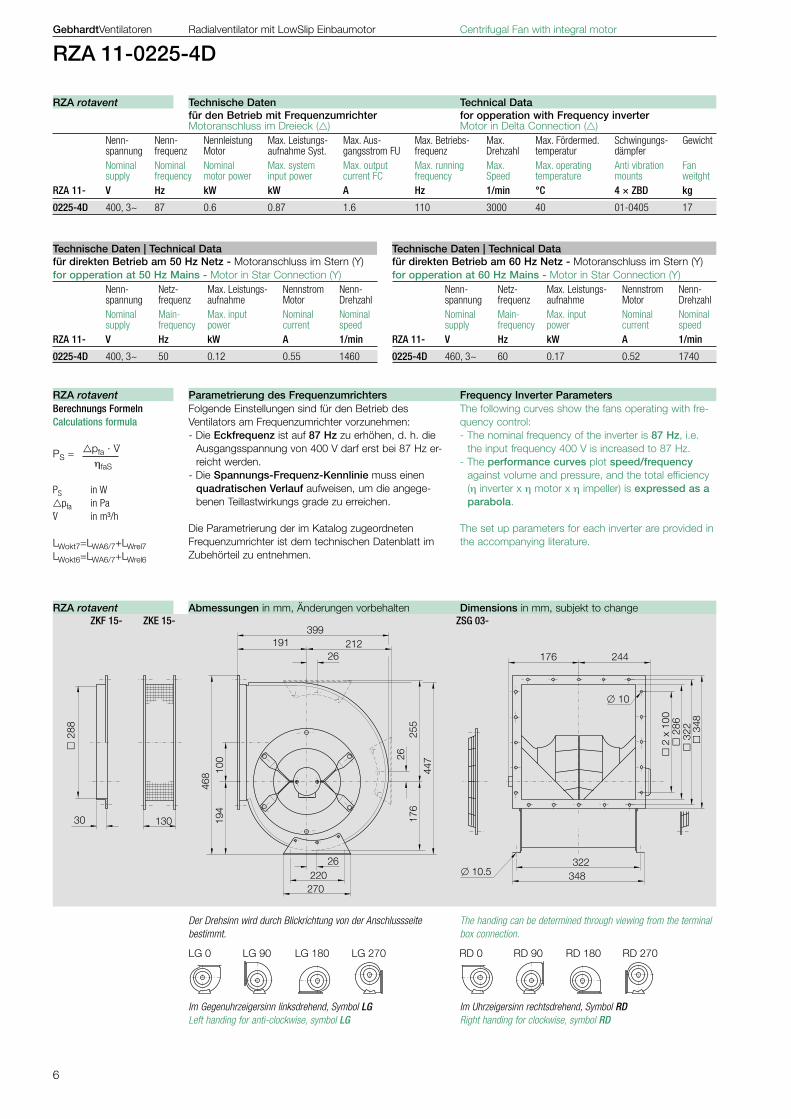
RZA 11-0225-4D
Im Gegenuhrzeigersinn linksdrehend, Symbol LGLeft handing for anti-clockwise, symbol LG
für den Betrieb mit Frequenzumrichter for opperation with Frequency inverter Motoranschluss im Dreieck () Motor in Delta Connection () Nenn- Nenn- Nennleistung Max. Leistungs- Max. Aus- Max. Betriebs- Max. Max. Fördermed. Schwingungs- Gewicht spannung frequenz Motor aufnahme Syst. gangsstrom FU frequenz Drehzahl temperatur dämpfer Nominal Nominal Nominal Max. system Max. output Max. running Max. Max. operating Anti vibration Fan supply frequency motor power input power current FC frequency Speed temperature mounts weitghtRZA 11- V Hz kW kW A Hz 1/min °C 4 × ZBD kg
0225-4D 400, 3~ 87 0.6 0.87 1.6 110 3000 40 01-0405 17
für direkten Betrieb am 60 Hz Netz - Motoranschluss im Stern (Y)for opperation at 60 Hz Mains - Motor in Star Connection (Y) Nenn- Netz- Max. Leistungs- Nennstrom Nenn- spannung frequenz aufnahme Motor Drehzahl Nominal Main- Max. input Nominal Nominal supply frequency power current speedRZA 11- V Hz kW A 1/min
0225-4D 460, 3~ 60 0.17 0.52 1740
für direkten Betrieb am 50 Hz Netz - Motoranschluss im Stern (Y)for opperation at 50 Hz Mains - Motor in Star Connection (Y) Nenn- Netz- Max. Leistungs- Nennstrom Nenn- spannung frequenz aufnahme Motor Drehzahl Nominal Main- Max. input Nominal Nominal supply frequency power current speedRZA 11- V Hz kW A 1/min
0225-4D 400, 3~ 50 0.12 0.55 1460
Folgende Einstellungen sind für den Betrieb des Ventilators am Frequenzumrichter vorzunehmen:- Die Eckfrequenz ist auf 87 Hz zu erhöhen, d. h. die
Ausgangsspannung von 400 V darf erst bei 87 Hz er-reicht werden.
- Die Spannungs-Frequenz-Kennlinie muss einen quadratischen Verlauf aufweisen, um die angege-benen Teillastwirkungs grade zu erreichen.
Die Parametrierung der im Katalog zugeordneten Frequenzumrichter ist dem technischen Datenblatt im Zubehörteil zu entnehmen.
Berechnungs Formeln Calculations formula
pfa · V. PS =
ηfaS
PS in Wpfa in PaV. in m³/h
LWokt7=LWA6/7+LWrel7 LWokt6=LWA6/7+LWrel6
ZKF 15- ZKE 15- ZSG 03-
Der Drehsinn wird durch Blickrichtung von der Anschlussseite bestimmt.
The handing can be determined through viewing from the terminal box connection.
Im Uhrzeigersinn rechtsdrehend, Symbol RD Right handing for clockwise, symbol RD
The following curves show the fans operating with fre-quency control:- The nominal frequency of the inverter is 87 Hz, i.e.
the input frequency 400 V is increased to 87 Hz.- The performance curves plot speed/frequency
against volume and pressure, and the total efficiency (η inverter x η motor x η impeller) is expressed as a parabola.
The set up parameters for each inverter are provided in the accompanying literature.
Technische Daten Technical DataRZA rotavent
Technische Daten | Technical Data Technische Daten | Technical Data
Parametrierung des Frequenzumrichters Frequency Inverter ParametersRZA rotavent
Abmessungen in mm, Änderungen vorbehalten Dimensions in mm, subjekt to changeRZA rotavent
7
RZA
11-0
225-
4D
2000
1000
600
400
200
100
40
Pa
500
300
800
60
50
80
1500
150
1200
120
2000 40003000 m³/h
�p f
a
150012001000
3000
2600
2300
2000
1800
1600
n
1/min 110
91
80
69
62
55
f
Hz
V ·0.15 0.2
500 600 800
m³/s
V ·
0.3 0.4 0.5 0.6 0.7 0.8 0.9 1.0
ηfaS für n
max
20
30
41 % 4445
40
44
81
72
6978
75
L WA6;7
84 dB
P S
0.3
0.4
0.60.5
0.15
0.2
kW
GebhardtVentilatoren Radialventilator mit LowSlip Einbaumotor Centrifugal Fan with integral motor
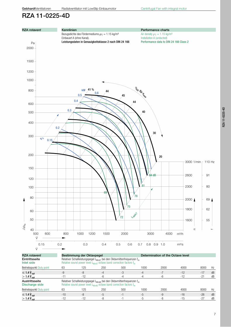
RZA 11-0225-4D
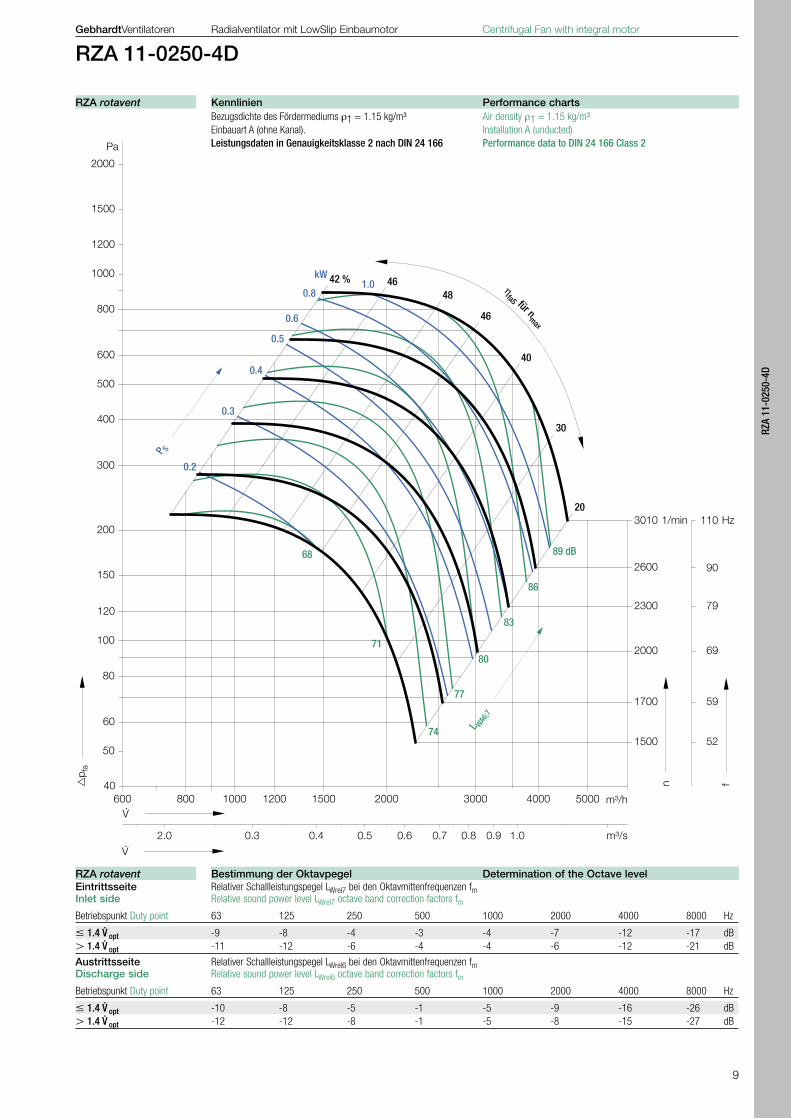
Bezugsdichte des Fördermediums ρ1 = 1.15 kg/m³ Air density ρ1 = 1.15 kg/m³ Einbauart A (ohne Kanal). Installation A (unducted) Leistungsdaten in Genauigkeitsklasse 2 nach DIN 24 166 Performance data to DIN 24 166 Class 2
Eintrittsseite Relativer Schallleistungspegel LWrel7 bei den Oktavmittenfrequenzen fm Inlet side Relative sound power level LWrel7 octave band correction factors fm
Betriebspunkt Duty point 63 125 250 500 1000 2000 4000 8000 Hz
1.4 V. opt -9 -8 -4 -3 -4 -7 -12 -17 dB
1.4 V. opt -11 -12 -6 -4 -4 -6 -12 -21 dB
Austrittsseite Relativer Schallleistungspegel LWrel6 bei den Oktavmittenfrequenzen fm Discharge side Relative sound power level LWrel6 octave band correction factors fm
Betriebspunkt Duty point 63 125 250 500 1000 2000 4000 8000 Hz
1.4 V. opt -10 -8 -5 -1 -5 -9 -16 -26 dB
1.4 V. opt -12 -12 -8 -1 -5 -8 -15 -27 dB
Kennlinien Performance chartsRZA rotavent
Bestimmung der Oktavpegel Determination of the Octave levelRZA rotavent
8
438
28234206
490
270220
28
2828
2
511
210
110
130
381356
10.5
3
82
356
3
20
3 x
100
244
10
3
22
30 194
LG 0 LG 90 LG 180 LG 270 RD 0 RD 90 RD 180 RD 270
GebhardtVentilatoren Radialventilator mit LowSlip Einbaumotor Centrifugal Fan with integral motor
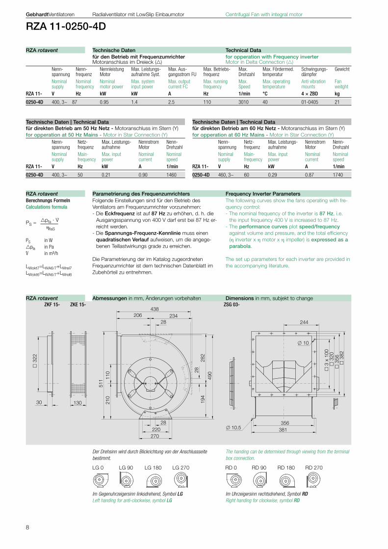
RZA 11-0250-4D
für den Betrieb mit Frequenzumrichter for opperation with Frequency inverter Motoranschluss im Dreieck () Motor in Delta Connection () Nenn- Nenn- Nennleistung Max. Leistungs- Max. Aus- Max. Betriebs- Max. Max. Fördermed. Schwingungs- Gewicht spannung frequenz Motor aufnahme Syst. gangsstrom FU frequenz Drehzahl temperatur dämpfer Nominal Nominal Nominal Max. system Max. output Max. running Max. Max. operating Anti vibration Fan supply frequency motor power input power current FC frequency Speed temperature mounts weitghtRZA 11- V Hz kW kW A Hz 1/min °C 4 × ZBD kg
0250-4D 400, 3~ 87 0.95 1.4 2.5 110 3010 40 01-0405 21
für direkten Betrieb am 60 Hz Netz - Motoranschluss im Stern (Y)for opperation at 60 Hz Mains - Motor in Star Connection (Y) Nenn- Netz- Max. Leistungs- Nennstrom Nenn- spannung frequenz aufnahme Motor Drehzahl Nominal Main- Max. input Nominal Nominal supply frequency power current speedRZA 11- V Hz kW A 1/min
0250-4D 460, 3~ 60 0.29 0.87 1740
für direkten Betrieb am 50 Hz Netz - Motoranschluss im Stern (Y)for opperation at 50 Hz Mains - Motor in Star Connection (Y) Nenn- Netz- Max. Leistungs- Nennstrom Nenn- spannung frequenz aufnahme Motor Drehzahl Nominal Main- Max. input Nominal Nominal supply frequency power current speedRZA 11- V Hz kW A 1/min
0250-4D 400, 3~ 50 0.21 0.90 1460
Im Gegenuhrzeigersinn linksdrehend, Symbol LGLeft handing for anti-clockwise, symbol LG
Der Drehsinn wird durch Blickrichtung von der Anschlussseite bestimmt.
The handing can be determined through viewing from the terminal box connection.
Im Uhrzeigersinn rechtsdrehend, Symbol RD Right handing for clockwise, symbol RD
Folgende Einstellungen sind für den Betrieb des Ventilators am Frequenzumrichter vorzunehmen:- Die Eckfrequenz ist auf 87 Hz zu erhöhen, d. h. die
Ausgangsspannung von 400 V darf erst bei 87 Hz er-reicht werden.
- Die Spannungs-Frequenz-Kennlinie muss einen quadratischen Verlauf aufweisen, um die angege-benen Teillastwirkungs grade zu erreichen.
Die Parametrierung der im Katalog zugeordneten Frequenzumrichter ist dem technischen Datenblatt im Zubehörteil zu entnehmen.
Berechnungs Formeln Calculations formula
pfa · V. PS =
ηfaS
PS in Wpfa in PaV. in m³/h
LWokt7=LWA6/7+LWrel7 LWokt6=LWA6/7+LWrel6
The following curves show the fans operating with fre-quency control:- The nominal frequency of the inverter is 87 Hz, i.e.
the input frequency 400 V is increased to 87 Hz.- The performance curves plot speed/frequency
against volume and pressure, and the total efficiency (η inverter x η motor x η impeller) is expressed as a parabola.
The set up parameters for each inverter are provided in the accompanying literature.
ZKF 15- ZKE 15- ZSG 03-
Technische Daten Technical DataRZA rotavent
Technische Daten | Technical Data Technische Daten | Technical Data
Parametrierung des Frequenzumrichters Frequency Inverter ParametersRZA rotavent
Abmessungen in mm, Änderungen vorbehalten Dimensions in mm, subjekt to changeRZA rotavent
9
RZA
11-0
250-
4D
2000
1000
600
400
200
100
40
Pa
500
300
800
60
50
80
1500
150
1200
120
2000 40003000 m³/h
�p f
a
5000150012001000
3010
2600
2300
2000
1700
1500
n
1/min 110
90
79
69
59
52
f
Hz
V ·2.0
600 800
m³/s
V ·
0.3 0.4 0.5 0.6 0.7 0.8 0.9 1.0
ηfaS für n
max
20
40
42 % 4648
30
46
80
83
86
68
71
77
74 L WA6;7
89 dB
P S
0.3
0.2
1.0
0.4
0.6
0.5
0.8
kW
GebhardtVentilatoren Radialventilator mit LowSlip Einbaumotor Centrifugal Fan with integral motor
RZA 11-0250-4D
Bezugsdichte des Fördermediums ρ1 = 1.15 kg/m³ Air density ρ1 = 1.15 kg/m³ Einbauart A (ohne Kanal). Installation A (unducted) Leistungsdaten in Genauigkeitsklasse 2 nach DIN 24 166 Performance data to DIN 24 166 Class 2
Eintrittsseite Relativer Schallleistungspegel LWrel7 bei den Oktavmittenfrequenzen fm Inlet side Relative sound power level LWrel7 octave band correction factors fm
Betriebspunkt Duty point 63 125 250 500 1000 2000 4000 8000 Hz
1.4 V. opt -9 -8 -4 -3 -4 -7 -12 -17 dB
1.4 V. opt -11 -12 -6 -4 -4 -6 -12 -21 dB
Austrittsseite Relativer Schallleistungspegel LWrel6 bei den Oktavmittenfrequenzen fm Discharge side Relative sound power level LWrel6 octave band correction factors fm
Betriebspunkt Duty point 63 125 250 500 1000 2000 4000 8000 Hz
1.4 V. opt -10 -8 -5 -1 -5 -9 -16 -26 dB
1.4 V. opt -12 -12 -8 -1 -5 -8 -15 -27 dB
Kennlinien Performance chartsRZA rotavent
Bestimmung der Oktavpegel Determination of the Octave levelRZA rotavent

10
484
30263226
548
270220
30
3031
5
570
236
123
130
421395
10.5
4
21
395
3
58
3 x
100
286
10
3
61
30 216
222
LG 0 LG 90 LG 180 LG 270 RD 0 RD 90 RD 180 RD 270
GebhardtVentilatoren Radialventilator mit LowSlip Einbaumotor Centrifugal Fan with integral motor
RZA 11-0280-4D
für den Betrieb mit Frequenzumrichter for opperation with Frequency inverter Motoranschluss im Dreieck () Motor in Delta Connection () Nenn- Nenn- Nennleistung Max. Leistungs- Max. Aus- Max. Betriebs- Max. Max. Fördermed. Schwingungs- Gewicht spannung frequenz Motor aufnahme Syst. gangsstrom FU frequenz Drehzahl temperatur dämpfer Nominal Nominal Nominal Max. system Max. output Max. running Max. Max. operating Anti vibration Fan supply frequency motor power input power current FC frequency Speed temperature mounts weitghtRZA 11- V Hz kW kW A Hz 1/min °C 4 × ZBD kg
0280-4D 400, 3~ 87 1.5 1.9 3.7 100 2900 40 01-0405 29
für direkten Betrieb am 60 Hz Netz - Motoranschluss im Stern (Y)for opperation at 60 Hz Mains - Motor in Star Connection (Y) Nenn- Netz- Max. Leistungs- Nennstrom Nenn- spannung frequenz aufnahme Motor Drehzahl Nominal Main- Max. input Nominal Nominal supply frequency power current speedRZA 11- V Hz kW A 1/min
0280-4D 460, 3~ 60 0.49 1.35 1770
für direkten Betrieb am 50 Hz Netz - Motoranschluss im Stern (Y)for opperation at 50 Hz Mains - Motor in Star Connection (Y) Nenn- Netz- Max. Leistungs- Nennstrom Nenn- spannung frequenz aufnahme Motor Drehzahl Nominal Main- Max. input Nominal Nominal supply frequency power current speedRZA 11- V Hz kW A 1/min
0280-4D 400, 3~ 50 0.33 1.36 1480
Im Gegenuhrzeigersinn linksdrehend, Symbol LGLeft handing for anti-clockwise, symbol LG
Der Drehsinn wird durch Blickrichtung von der Anschlussseite bestimmt.
The handing can be determined through viewing from the terminal box connection.
Im Uhrzeigersinn rechtsdrehend, Symbol RD Right handing for clockwise, symbol RD
Folgende Einstellungen sind für den Betrieb des Ventilators am Frequenzumrichter vorzunehmen:- Die Eckfrequenz ist auf 87 Hz zu erhöhen, d. h. die
Ausgangsspannung von 400 V darf erst bei 87 Hz er-reicht werden.
- Die Spannungs-Frequenz-Kennlinie muss einen quadratischen Verlauf aufweisen, um die angege-benen Teillastwirkungs grade zu erreichen.
Die Parametrierung der im Katalog zugeordneten Frequenzumrichter ist dem technischen Datenblatt im Zubehörteil zu entnehmen.
Berechnungs Formeln Calculations formula
pfa · V. PS =
ηfaS
PS in Wpfa in PaV. in m³/h
LWokt7=LWA6/7+LWrel7 LWokt6=LWA6/7+LWrel6
The following curves show the fans operating with fre-quency control:- The nominal frequency of the inverter is 87 Hz, i.e.
the input frequency 400 V is increased to 87 Hz.- The performance curves plot speed/frequency
against volume and pressure, and the total efficiency (η inverter x η motor x η impeller) is expressed as a parabola.
The set up parameters for each inverter are provided in the accompanying literature.
ZKF 15- ZKE 15- ZSG 03-
Technische Daten Technical DataRZA rotavent
Technische Daten | Technical Data Technische Daten | Technical Data
Parametrierung des Frequenzumrichters Frequency Inverter ParametersRZA rotavent
Abmessungen in mm, Änderungen vorbehalten Dimensions in mm, subjekt to changeRZA rotavent
11
RZA
11-0
280-
4D
2000
1000
600
400
200
100
40
Pa
500
300
800
60
50
80
1500
150
1200
120
2000 40003000 m³/h
�p f
a
5000150012001000
2900
2700
2300
1900
1700
1500
n
1/min 100
93
79
65
58
51f
Hz
V ·1.5
800
m³/s
V ·
0.3 0.4 0.5 0.6 0.7 0.8 0.9 1.0
6000
1400 48
2100 72
2500 86
ηfaS für n
max
20
40
44 % 50
52
30
50
81
84
8772
78
75 L WA6;7
90 dB
P S
0.3
1.3
1.0
0.4
0.6
0.5
0.8
kW
GebhardtVentilatoren Radialventilator mit LowSlip Einbaumotor Centrifugal Fan with integral motor
RZA 11-0280-4D
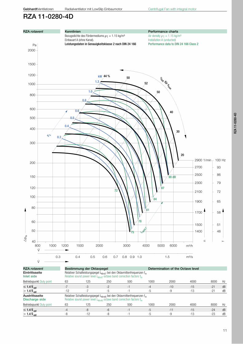
Bezugsdichte des Fördermediums ρ1 = 1.15 kg/m³ Air density ρ1 = 1.15 kg/m³ Einbauart A (ohne Kanal). Installation A (unducted) Leistungsdaten in Genauigkeitsklasse 2 nach DIN 24 166 Performance data to DIN 24 166 Class 2
Eintrittsseite Relativer Schallleistungspegel LWrel7 bei den Oktavmittenfrequenzen fm Inlet side Relative sound power level LWrel7 octave band correction factors fm
Betriebspunkt Duty point 63 125 250 500 1000 2000 4000 8000 Hz
1.4 V. opt -7 -3 -2 -1 -4 -10 -15 -21 dB
1.4 V. opt -12 -7 -5 -1 -5 -9 -13 -21 dB
Austrittsseite Relativer Schallleistungspegel LWrel6 bei den Oktavmittenfrequenzen fm Discharge side Relative sound power level LWrel6 octave band correction factors fm
Betriebspunkt Duty point 63 125 250 500 1000 2000 4000 8000 Hz
1.4 V. opt -4 -8 -6 -1 -5 -11 -15 -24 dB
1.4 V. opt -8 -12 -8 -1 -5 -9 -13 -23 dB
Kennlinien Performance chartsRZA rotavent
Bestimmung der Oktavpegel Determination of the Octave levelRZA rotavent

12
536
33294247
603
270220
33
3335
5
624
253
139
130
463438
10.5
4
64
438
4
01
3 x
100
286
10
4
04
30 242
LG 0 LG 90 LG 180 LG 270 RD 0 RD 90 RD 180 RD 270
GebhardtVentilatoren Radialventilator mit LowSlip Einbaumotor Centrifugal Fan with integral motor
RZA 11-0315-4D
für den Betrieb mit Frequenzumrichter for opperation with Frequency inverter Motoranschluss im Dreieck () Motor in Delta Connection () Nenn- Nenn- Nennleistung Max. Leistungs- Max. Aus- Max. Betriebs- Max. Max. Fördermed. Schwingungs- Gewicht spannung frequenz Motor aufnahme Syst. gangsstrom FU frequenz Drehzahl temperatur dämpfer Nominal Nominal Nominal Max. system Max. output Max. running Max. Max. operating Anti vibration Fan supply frequency motor power input power current FC frequency Speed temperature mounts weitghtRZA 11- V Hz kW kW A Hz 1/min °C 4 × ZBD kg
0315-4D 400, 3~ 87 2.2 2.9 5.3 95 2750 40 01-0405 36
für direkten Betrieb am 60 Hz Netz - Motoranschluss im Stern (Y)for opperation at 60 Hz Mains - Motor in Star Connection (Y) Nenn- Netz- Max. Leistungs- Nennstrom Nenn- spannung frequenz aufnahme Motor Drehzahl Nominal Main- Max. input Nominal Nominal supply frequency power current speedRZA 11- V Hz kW A 1/min
0315-4D 460, 3~ 60 0.82 1.94 1770
für direkten Betrieb am 50 Hz Netz - Motoranschluss im Stern (Y)for opperation at 50 Hz Mains - Motor in Star Connection (Y) Nenn- Netz- Max. Leistungs- Nennstrom Nenn- spannung frequenz aufnahme Motor Drehzahl Nominal Main- Max. input Nominal Nominal supply frequency power current speedRZA 11- V Hz kW A 1/min
0315-4D 400, 3~ 50 0.54 1.89 1480
Im Gegenuhrzeigersinn linksdrehend, Symbol LGLeft handing for anti-clockwise, symbol LG
Der Drehsinn wird durch Blickrichtung von der Anschlussseite bestimmt.
The handing can be determined through viewing from the terminal box connection.
Im Uhrzeigersinn rechtsdrehend, Symbol RD Right handing for clockwise, symbol RD
Folgende Einstellungen sind für den Betrieb des Ventilators am Frequenzumrichter vorzunehmen:- Die Eckfrequenz ist auf 87 Hz zu erhöhen, d. h. die
Ausgangsspannung von 400 V darf erst bei 87 Hz er-reicht werden.
- Die Spannungs-Frequenz-Kennlinie muss einen quadratischen Verlauf aufweisen, um die angege-benen Teillastwirkungs grade zu erreichen.
Die Parametrierung der im Katalog zugeordneten Frequenzumrichter ist dem technischen Datenblatt im Zubehörteil zu entnehmen.
Berechnungs Formeln Calculations formula
pfa · V. PS =
ηfaS
PS in Wpfa in PaV. in m³/h
LWokt7=LWA6/7+LWrel7 LWokt6=LWA6/7+LWrel6
The following curves show the fans operating with fre-quency control:- The nominal frequency of the inverter is 87 Hz, i.e.
the input frequency 400 V is increased to 87 Hz.- The performance curves plot speed/frequency
against volume and pressure, and the total efficiency (η inverter x η motor x η impeller) is expressed as a parabola.
The set up parameters for each inverter are provided in the accompanying literature.
ZKF 15- ZKE 15- ZSG 03-
Technische Daten Technical DataRZA rotavent
Technische Daten | Technical Data Technische Daten | Technical Data
Parametrierung des Frequenzumrichters Frequency Inverter ParametersRZA rotavent
Abmessungen in mm, Änderungen vorbehalten Dimensions in mm, subjekt to changeRZA rotavent
13
RZA
11-0
315-
4D
2000
1000
600
400
200
100
40
Pa
500
300
800
60
50
80
1500
150
1200
120
2000 40003000 m³/h
�p f
a
5000 6000 8000150012001000
2750
2300
2100
1900
1700
1500
1300
n
1/min 95
86
79
72
65
58
52
f
Hz
V ·
2500
45
m³/s
V ·
0.3 0.4 0.5 0.6 0.7 0.8 0.9 1.0 1.5 2.0
ηfaS für n
max
20
40
47 % 52
54
30
50
83
86
89
71
74
80
77 L WA6;7
92 dB
P S
0.3
2.0
1.0
0.4
0.6
0.5
0.8
kW
1.5
2.5
GebhardtVentilatoren Radialventilator mit LowSlip Einbaumotor Centrifugal Fan with integral motor
RZA 11-0315-4D
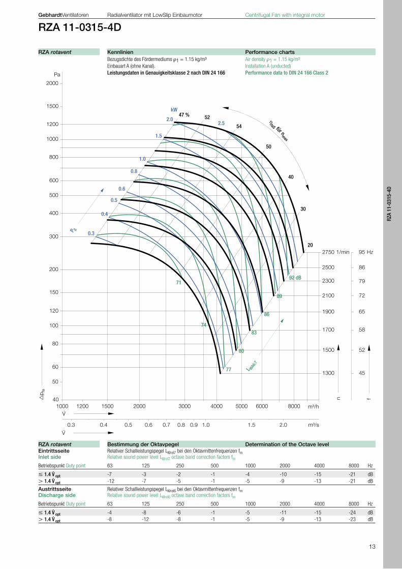
Bezugsdichte des Fördermediums ρ1 = 1.15 kg/m³ Air density ρ1 = 1.15 kg/m³ Einbauart A (ohne Kanal). Installation A (unducted) Leistungsdaten in Genauigkeitsklasse 2 nach DIN 24 166 Performance data to DIN 24 166 Class 2
Eintrittsseite Relativer Schallleistungspegel LWrel7 bei den Oktavmittenfrequenzen fm Inlet side Relative sound power level LWrel7 octave band correction factors fm
Betriebspunkt Duty point 63 125 250 500 1000 2000 4000 8000 Hz
1.4 V. opt -7 -3 -2 -1 -4 -10 -15 -21 dB
1.4 V. opt -12 -7 -5 -1 -5 -9 -13 -21 dB
Austrittsseite Relativer Schallleistungspegel LWrel6 bei den Oktavmittenfrequenzen fm Discharge side Relative sound power level LWrel6 octave band correction factors fm
Betriebspunkt Duty point 63 125 250 500 1000 2000 4000 8000 Hz
1.4 V. opt -4 -8 -6 -1 -5 -11 -15 -24 dB
1.4 V. opt -8 -12 -8 -1 -5 -9 -13 -23 dB
Kennlinien Performance chartsRZA rotavent
Bestimmung der Oktavpegel Determination of the Octave levelRZA rotavent

14
598
36329273
668
270220
36
3629
7
689
275
157
130
513487
10.5
5
13
487
4
50
4 x
100
334
10
4
53
30 271
275
LG 0 LG 90 LG 180 LG 270 RD 0 RD 90 RD 180 RD 270
GebhardtVentilatoren Radialventilator mit LowSlip Einbaumotor Centrifugal Fan with integral motor
RZA 11-0355-4D
für den Betrieb mit Frequenzumrichter for opperation with Frequency inverter Motoranschluss im Dreieck () Motor in Delta Connection () Nenn- Nenn- Nennleistung Max. Leistungs- Max. Aus- Max. Betriebs- Max. Max. Fördermed. Schwingungs- Gewicht spannung frequenz Motor aufnahme Syst. gangsstrom FU frequenz Drehzahl temperatur dämpfer Nominal Nominal Nominal Max. system Max. output Max. running Max. Max. operating Anti vibration Fan supply frequency motor power input power current FC frequency Speed temperature mounts weitghtRZA 11- V Hz kW kW A Hz 1/min °C 4 × ZBD kg
0355-4D 400, 3~ 87 3.6 4.6 7.9 90 2620 40 01-0405 48
für direkten Betrieb am 60 Hz Netz - Motoranschluss im Stern (Y)for opperation at 60 Hz Mains - Motor in Star Connection (Y) Nenn- Netz- Max. Leistungs- Nennstrom Nenn- spannung frequenz aufnahme Motor Drehzahl Nominal Main- Max. input Nominal Nominal supply frequency power current speedRZA 11- V Hz kW A 1/min
0355-4D 460, 3~ 60 1.30 2.40 1770
für direkten Betrieb am 50 Hz Netz - Motoranschluss im Stern (Y)for opperation at 50 Hz Mains - Motor in Star Connection (Y) Nenn- Netz- Max. Leistungs- Nennstrom Nenn- spannung frequenz aufnahme Motor Drehzahl Nominal Main- Max. input Nominal Nominal supply frequency power current speedRZA 11- V Hz kW A 1/min
0355-4D 400, 3~ 50 0.79 2.20 1480
Im Gegenuhrzeigersinn linksdrehend, Symbol LGLeft handing for anti-clockwise, symbol LG
Der Drehsinn wird durch Blickrichtung von der Anschlussseite bestimmt.
The handing can be determined through viewing from the terminal box connection.
Im Uhrzeigersinn rechtsdrehend, Symbol RD Right handing for clockwise, symbol RD
Folgende Einstellungen sind für den Betrieb des Ventilators am Frequenzumrichter vorzunehmen:- Die Eckfrequenz ist auf 87 Hz zu erhöhen, d. h. die
Ausgangsspannung von 400 V darf erst bei 87 Hz er-reicht werden.
- Die Spannungs-Frequenz-Kennlinie muss einen quadratischen Verlauf aufweisen, um die angege-benen Teillastwirkungs grade zu erreichen.
Die Parametrierung der im Katalog zugeordneten Frequenzumrichter ist dem technischen Datenblatt im Zubehörteil zu entnehmen.
Berechnungs Formeln Calculations formula
pfa · V. PS =
ηfaS
PS in Wpfa in PaV. in m³/h
LWokt7=LWA6/7+LWrel7 LWokt6=LWA6/7+LWrel6
The following curves show the fans operating with fre-quency control:- The nominal frequency of the inverter is 87 Hz, i.e.
the input frequency 400 V is increased to 87 Hz.- The performance curves plot speed/frequency
against volume and pressure, and the total efficiency (η inverter x η motor x η impeller) is expressed as a parabola.
The set up parameters for each inverter are provided in the accompanying literature.
ZKF 15- ZKE 15- ZSG 03-
Technische Daten Technical DataRZA rotavent
Technische Daten | Technical Data Technische Daten | Technical Data
Parametrierung des Frequenzumrichters Frequency Inverter ParametersRZA rotavent
Abmessungen in mm, Änderungen vorbehalten Dimensions in mm, subjekt to changeRZA rotavent
15
RZA
11-0
355-
4D
2000
1000
600
400
200
100
40
Pa
500
300
800
60
50
80
1500
150
1200
120
2000 40003000 m³/h
�p f
a
5000 6000 80001500
2620
2200
2000
1800
1600
1400
1200
n
1/min 90
83
76
69
62
55
48
f
Hz
V ·
2400
42
m³/s
V ·
3.00.5 0.6 0.7 0.8 0.9 1.0 1.5 2.0
10000
ηfaS für n
max
30
50
53 %56
58
40
56
20
83
86
89
71
74
80
77
L WA6;7
95 dB
92
P S
2.7
2.0
1.0
0.4
0.6
0.5
0.8
kW
1.5
GebhardtVentilatoren Radialventilator mit LowSlip Einbaumotor Centrifugal Fan with integral motor
RZA 11-0355-4D
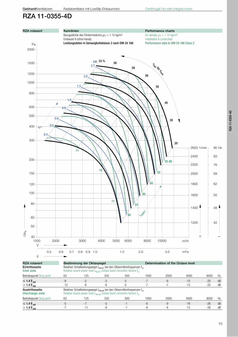
Bezugsdichte des Fördermediums ρ1 = 1.15 kg/m³ Air density ρ1 = 1.15 kg/m³ Einbauart A (ohne Kanal). Installation A (unducted) Leistungsdaten in Genauigkeitsklasse 2 nach DIN 24 166 Performance data to DIN 24 166 Class 2
Eintrittsseite Relativer Schallleistungspegel LWrel7 bei den Oktavmittenfrequenzen fm Inlet side Relative sound power level LWrel7 octave band correction factors fm
Betriebspunkt Duty point 63 125 250 500 1000 2000 4000 8000 Hz
1.4 V. opt -9 -2 -3 0 -7 -9 -15 -25 dB
1.4 V. opt -12 -6 -6 0 -7 -7 -13 -25 dB
Austrittsseite Relativer Schallleistungspegel LWrel6 bei den Oktavmittenfrequenzen fm Discharge side Relative sound power level LWrel6 octave band correction factors fm
Betriebspunkt Duty point 63 125 250 500 1000 2000 4000 8000 Hz
1.4 V. opt -5 -7 -5 -1 -6 -9 -16 -26 dB
1.4 V. opt -7 -11 -8 -1 -6 -8 -13 -26 dB
Kennlinien Performance chartsRZA rotavent
Bestimmung der Oktavpegel Determination of the Octave levelRZA rotavent

16
667
40369302
751
385320
40
4044
5
773
310
179
130
596546
14
5
67
541
5
04
4 x
100
334
10
5
07
30 304
LG 0 LG 90 LG 180 LG 270 RD 0 RD 90 RD 180 RD 270
GebhardtVentilatoren Radialventilator mit LowSlip Einbaumotor Centrifugal Fan with integral motor
RZA 11-0400-4D
für den Betrieb mit Frequenzumrichter for opperation with Frequency inverter Motoranschluss im Dreieck () Motor in Delta Connection () Nenn- Nenn- Nennleistung Max. Leistungs- Max. Aus- Max. Betriebs- Max. Max. Fördermed. Schwingungs- Gewicht spannung frequenz Motor aufnahme Syst. gangsstrom FU frequenz Drehzahl temperatur dämpfer Nominal Nominal Nominal Max. system Max. output Max. running Max. Max. operating Anti vibration Fan supply frequency motor power input power current FC frequency Speed temperature mounts weitghtRZA 11- V Hz kW kW A Hz 1/min °C 4 × ZBD kg
0400-4D 400, 3~ 87 4.4 5.6 12.0 80 2330 40 01-0405 68
für direkten Betrieb am 60 Hz Netz - Motoranschluss im Stern (Y)for opperation at 60 Hz Mains - Motor in Star Connection (Y) Nenn- Netz- Max. Leistungs- Nennstrom Nenn- spannung frequenz aufnahme Motor Drehzahl Nominal Main- Max. input Nominal Nominal supply frequency power current speedRZA 11- V Hz kW A 1/min
0400-4D 460, 3~ 60 2.41 4.20 1770
für direkten Betrieb am 50 Hz Netz - Motoranschluss im Stern (Y)for opperation at 50 Hz Mains - Motor in Star Connection (Y) Nenn- Netz- Max. Leistungs- Nennstrom Nenn- spannung frequenz aufnahme Motor Drehzahl Nominal Main- Max. input Nominal Nominal supply frequency power current speedRZA 11- V Hz kW A 1/min
0400-4D 400, 3~ 50 1.46 3.50 1480
Im Gegenuhrzeigersinn linksdrehend, Symbol LGLeft handing for anti-clockwise, symbol LG
Der Drehsinn wird durch Blickrichtung von der Anschlussseite bestimmt.
The handing can be determined through viewing from the terminal box connection.
Im Uhrzeigersinn rechtsdrehend, Symbol RD Right handing for clockwise, symbol RD
Folgende Einstellungen sind für den Betrieb des Ventilators am Frequenzumrichter vorzunehmen:- Die Eckfrequenz ist auf 87 Hz zu erhöhen, d. h. die
Ausgangsspannung von 400 V darf erst bei 87 Hz er-reicht werden.
- Die Spannungs-Frequenz-Kennlinie muss einen quadratischen Verlauf aufweisen, um die angege-benen Teillastwirkungs grade zu erreichen.
Die Parametrierung der im Katalog zugeordneten Frequenzumrichter ist dem technischen Datenblatt im Zubehörteil zu entnehmen.
Berechnungs Formeln Calculations formula
pfa · V. PS =
ηfaS
PS in Wpfa in PaV. in m³/h
LWokt7=LWA6/7+LWrel7 LWokt6=LWA6/7+LWrel6
The following curves show the fans operating with fre-quency control:- The nominal frequency of the inverter is 87 Hz, i.e.
the input frequency 400 V is increased to 87 Hz.- The performance curves plot speed/frequency
against volume and pressure, and the total efficiency (η inverter x η motor x η impeller) is expressed as a parabola.
The set up parameters for each inverter are provided in the accompanying literature.
ZKF 15- ZKE 15- ZSG 03-
Technische Daten Technical DataRZA rotavent
Technische Daten | Technical Data Technische Daten | Technical Data
Parametrierung des Frequenzumrichters Frequency Inverter ParametersRZA rotavent
Abmessungen in mm, Änderungen vorbehalten Dimensions in mm, subjekt to changeRZA rotavent
17
RZA
11-0
400-
4D
2000
1000
600
400
200
100
40
Pa
500
300
800
60
50
80
1500
150
1200
120
2000 40003000 m³/h
�p f
a
5000 6000 8000
2330
2000
1800
1600
1400
1300
1200
n
1/min 80
76
69
62
55
48
45
f
Hz
V ·
2200
41
m³/s
V ·
0.6 0.7 0.8 0.9 1.0 1.5 2.0
10000 12000
3.0
1100 38
15000
4.0
ηfaS für n
max
30
50
53 % 5860
40
58
20
83
86
89
74
80
77
L WA6;7
95 dB
92
P S
3.0
2.0
1.0
2.5
0.6
4.0
0.8
kW
1.5
GebhardtVentilatoren Radialventilator mit LowSlip Einbaumotor Centrifugal Fan with integral motor
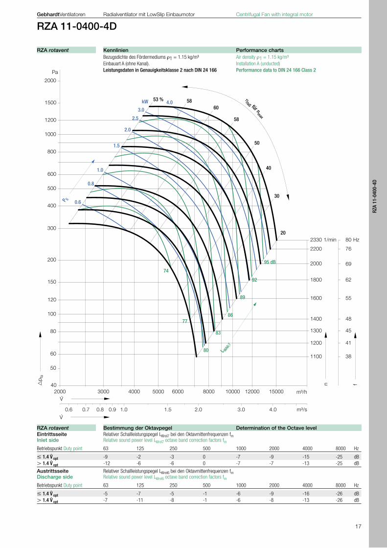
RZA 11-0400-4D
Bezugsdichte des Fördermediums ρ1 = 1.15 kg/m³ Air density ρ1 = 1.15 kg/m³ Einbauart A (ohne Kanal). Installation A (unducted) Leistungsdaten in Genauigkeitsklasse 2 nach DIN 24 166 Performance data to DIN 24 166 Class 2
Eintrittsseite Relativer Schallleistungspegel LWrel7 bei den Oktavmittenfrequenzen fm Inlet side Relative sound power level LWrel7 octave band correction factors fm
Betriebspunkt Duty point 63 125 250 500 1000 2000 4000 8000 Hz
1.4 V. opt -9 -2 -3 0 -7 -9 -15 -25 dB
1.4 V. opt -12 -6 -6 0 -7 -7 -13 -25 dB
Austrittsseite Relativer Schallleistungspegel LWrel6 bei den Oktavmittenfrequenzen fm Discharge side Relative sound power level LWrel6 octave band correction factors fm
Betriebspunkt Duty point 63 125 250 500 1000 2000 4000 8000 Hz
1.4 V. opt -5 -7 -5 -1 -6 -9 -16 -26 dB
1.4 V. opt -7 -11 -8 -1 -6 -8 -13 -26 dB
Kennlinien Performance chartsRZA rotavent
Bestimmung der Oktavpegel Determination of the Octave levelRZA rotavent
18
750
44413342
842
385320
44
4449
9
868
346
202
130
660612
14
6
39
605
5
66
4 x
112
400
12
5
69
35 341
340
LG 0 LG 90 LG 180 LG 270 RD 0 RD 90 RD 180 RD 270
GebhardtVentilatoren Radialventilator mit LowSlip Einbaumotor Centrifugal Fan with integral motor
RZA 11-0450-4D
für den Betrieb mit Frequenzumrichter for opperation with Frequency inverter Motoranschluss im Dreieck () Motor in Delta Connection () Nenn- Nenn- Nennleistung Max. Leistungs- Max. Aus- Max. Betriebs- Max. Max. Fördermed. Schwingungs- Gewicht spannung frequenz Motor aufnahme Syst. gangsstrom FU frequenz Drehzahl temperatur dämpfer Nominal Nominal Nominal Max. system Max. output Max. running Max. Max. operating Anti vibration Fan supply frequency motor power input power current FC frequency Speed temperature mounts weitghtRZA 11- V Hz kW kW A Hz 1/min °C 4 × ZBD kg
0450-4D 400, 3~ 87 5.2 6.6 15.8 70 2040 40 01-0504 85
für direkten Betrieb am 60 Hz Netz - Motoranschluss im Stern (Y)for opperation at 60 Hz Mains - Motor in Star Connection (Y) Nenn- Netz- Max. Leistungs- Nennstrom Nenn- spannung frequenz aufnahme Motor Drehzahl Nominal Main- Max. input Nominal Nominal supply frequency power current speedRZA 11- V Hz kW A 1/min
11-0450-4D 460, 3~ 60 4.15 6.80 1770
für direkten Betrieb am 50 Hz Netz - Motoranschluss im Stern (Y)for opperation at 50 Hz Mains - Motor in Star Connection (Y) Nenn- Netz- Max. Leistungs- Nennstrom Nenn- spannung frequenz aufnahme Motor Drehzahl Nominal Main- Max. input Nominal Nominal supply frequency power current speedRZA 11- V Hz kW A 1/min
11-0450-4D 400, 3~ 50 2.47 5.70 1480
Im Gegenuhrzeigersinn linksdrehend, Symbol LGLeft handing for anti-clockwise, symbol LG
Der Drehsinn wird durch Blickrichtung von der Anschlussseite bestimmt.
The handing can be determined through viewing from the terminal box connection.
Im Uhrzeigersinn rechtsdrehend, Symbol RD Right handing for clockwise, symbol RD
Folgende Einstellungen sind für den Betrieb des Ventilators am Frequenzumrichter vorzunehmen:- Die Eckfrequenz ist auf 87 Hz zu erhöhen, d. h. die
Ausgangsspannung von 400 V darf erst bei 87 Hz er-reicht werden.
- Die Spannungs-Frequenz-Kennlinie muss einen quadratischen Verlauf aufweisen, um die angege-benen Teillastwirkungs grade zu erreichen.
Die Parametrierung der im Katalog zugeordneten Frequenzumrichter ist dem technischen Datenblatt im Zubehörteil zu entnehmen.
Berechnungs Formeln Calculations formula
pfa · V. PS =
ηfaS
PS in Wpfa in PaV. in m³/h
LWokt7=LWA6/7+LWrel7 LWokt6=LWA6/7+LWrel6
The following curves show the fans operating with fre-quency control:- The nominal frequency of the inverter is 87 Hz, i.e.
the input frequency 400 V is increased to 87 Hz.- The performance curves plot speed/frequency
against volume and pressure, and the total efficiency (η inverter x η motor x η impeller) is expressed as a parabola.
The set up parameters for each inverter are provided in the accompanying literature.
ZKF 15- ZKE 15- ZSG 03-
Technische Daten Technical DataRZA rotavent
Technische Daten | Technical Data Technische Daten | Technical Data
Parametrierung des Frequenzumrichters Frequency Inverter ParametersRZA rotavent
Abmessungen in mm, Änderungen vorbehalten Dimensions in mm, subjekt to changeRZA rotavent
19
RZA
11-0
450-
4D
2000
1000
600
400
200
100
40
Pa
500
300
800
60
50
80
1500
150
1200
120
40003000 m³/h
�p f
a
5000 6000 8000
2040
1800
1600
1400
1200
1100
n
1/min 70
62
55
48
41
f
Hz
V ·
38
m³/s
V ·
0.7 0.8 0.9 1.0 1.5 2.0
10000 12000
3.0
1000 35
15000
4.0
20000
6.0
ηfaS für n
max
30
50
54 % 5961
40
58
20
82
85
88
73
79
76
L WA6;7
94 dB
91
P S
3.0
2.0
1.0
4.0 5.0
0.8
kW
1.5
GebhardtVentilatoren Radialventilator mit LowSlip Einbaumotor Centrifugal Fan with integral motor
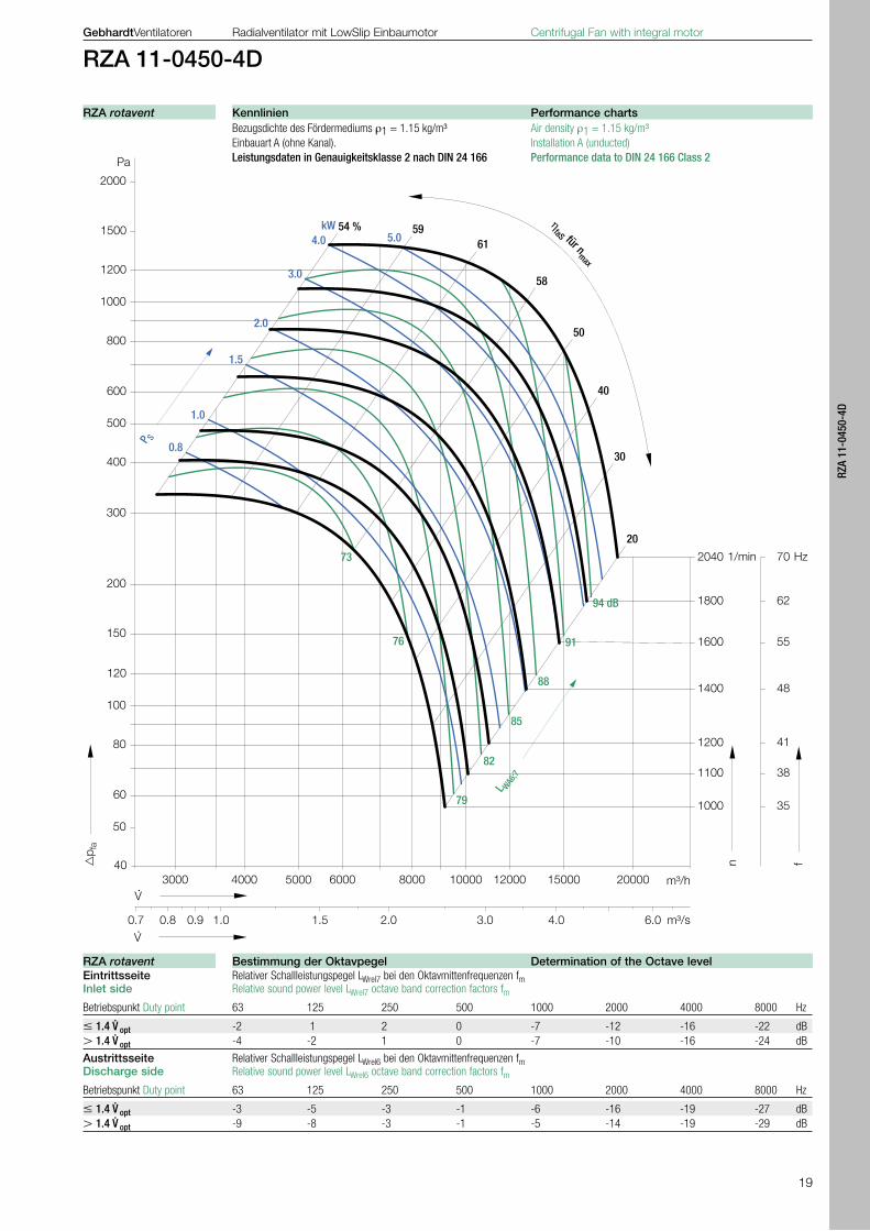
RZA 11-0450-4D
Bezugsdichte des Fördermediums ρ1 = 1.15 kg/m³ Air density ρ1 = 1.15 kg/m³ Einbauart A (ohne Kanal). Installation A (unducted) Leistungsdaten in Genauigkeitsklasse 2 nach DIN 24 166 Performance data to DIN 24 166 Class 2
Eintrittsseite Relativer Schallleistungspegel LWrel7 bei den Oktavmittenfrequenzen fm Inlet side Relative sound power level LWrel7 octave band correction factors fm
Betriebspunkt Duty point 63 125 250 500 1000 2000 4000 8000 Hz
1.4 V. opt -2 1 2 0 -7 -12 -16 -22 dB
1.4 V. opt -4 -2 1 0 -7 -10 -16 -24 dB
Austrittsseite Relativer Schallleistungspegel LWrel6 bei den Oktavmittenfrequenzen fm Discharge side Relative sound power level LWrel6 octave band correction factors fm
Betriebspunkt Duty point 63 125 250 500 1000 2000 4000 8000 Hz
1.4 V. opt -3 -5 -3 -1 -6 -16 -19 -27 dB
1.4 V. opt -9 -8 -3 -1 -5 -14 -19 -29 dB
Kennlinien Performance chartsRZA rotavent
Bestimmung der Oktavpegel Determination of the Octave levelRZA rotavent

20
821
52457370
929
385320
52
5255
3
956
381
221
130
729680
14
7
08
674
6
35
5 x
112
400
12
6
38
35 376
LG 0 LG 90 LG 180 LG 270 RD 0 RD 90 RD 180 RD 270
GebhardtVentilatoren Radialventilator mit LowSlip Einbaumotor Centrifugal Fan with integral motor
RZA 11-0500-6D
für den Betrieb mit Frequenzumrichter for opperation with Frequency inverter Motoranschluss im Dreieck () Motor in Delta Connection () Nenn- Nenn- Nennleistung Max. Leistungs- Max. Aus- Max. Betriebs- Max. Max. Fördermed. Schwingungs- Gewicht spannung frequenz Motor aufnahme Syst. gangsstrom FU frequenz Drehzahl temperatur dämpfer Nominal Nominal Nominal Max. system Max. output Max. running Max. Max. operating Anti vibration Fan supply frequency motor power input power current FC frequency Speed temperature mounts weitghtRZA 11- V Hz kW kW A Hz 1/min °C 4 × ZBD kg
0500-6D 400, 3~ 87 5.9 7.3 15.9 90 1770 40 01-0504 103
für direkten Betrieb am 60 Hz Netz - Motoranschluss im Stern (Y)for opperation at 60 Hz Mains - Motor in Star Connection (Y) Nenn- Netz- Max. Leistungs- Nennstrom Nenn- spannung frequenz aufnahme Motor Drehzahl Nominal Main- Max. input Nominal Nominal supply frequency power current speedRZA 11- V Hz kW A 1/min
0500-6D 460, 3~ 60 2.34 5.80 1180
für direkten Betrieb am 50 Hz Netz - Motoranschluss im Stern (Y)for opperation at 50 Hz Mains - Motor in Star Connection (Y) Nenn- Netz- Max. Leistungs- Nennstrom Nenn- spannung frequenz aufnahme Motor Drehzahl Nominal Main- Max. input Nominal Nominal supply frequency power current speedRZA 11- V Hz kW A 1/min
0500-6D 400, 3~ 50 1.39 5.70 990
Im Gegenuhrzeigersinn linksdrehend, Symbol LGLeft handing for anti-clockwise, symbol LG
Der Drehsinn wird durch Blickrichtung von der Anschlussseite bestimmt.
The handing can be determined through viewing from the terminal box connection.
Im Uhrzeigersinn rechtsdrehend, Symbol RD Right handing for clockwise, symbol RD
Folgende Einstellungen sind für den Betrieb des Ventilators am Frequenzumrichter vorzunehmen:- Die Eckfrequenz ist auf 87 Hz zu erhöhen, d. h. die
Ausgangsspannung von 400 V darf erst bei 87 Hz er-reicht werden.
- Die Spannungs-Frequenz-Kennlinie muss einen quadratischen Verlauf aufweisen, um die angege-benen Teillastwirkungs grade zu erreichen.
Die Parametrierung der im Katalog zugeordneten Frequenzumrichter ist dem technischen Datenblatt im Zubehörteil zu entnehmen.
Berechnungs Formeln Calculations formula
pfa · V. PS =
ηfaS
PS in Wpfa in PaV. in m³/h
LWokt7=LWA6/7+LWrel7 LWokt6=LWA6/7+LWrel6
The following curves show the fans operating with fre-quency control:- The nominal frequency of the inverter is 87 Hz, i.e.
the input frequency 400 V is increased to 87 Hz.- The performance curves plot speed/frequency
against volume and pressure, and the total efficiency (η inverter x η motor x η impeller) is expressed as a parabola.
The set up parameters for each inverter are provided in the accompanying literature.
ZKF 15- ZKE 15- ZSG 03-
Technische Daten Technical DataRZA rotavent
Technische Daten | Technical Data Technische Daten | Technical Data
Parametrierung des Frequenzumrichters Frequency Inverter ParametersRZA rotavent
Abmessungen in mm, Änderungen vorbehalten Dimensions in mm, subjekt to changeRZA rotavent
21
RZA
11-0
500-
6D
2000
1000
600
400
200
100
40
Pa
500
300
800
60
50
80
1500
150
1200
120
40003000 m³/h
�p f
a
5000 6000 8000
1770
1600
1400
1300
1200
1000
n
1/min 90
81
71
66
61
f
Hz
V ·
51
m³/s
V ·
0.9 1.0 1.5 2.0
10000 12000
3.0
900 45
15000
4.0
20000
6.0 7.05.0
1100 56
ηfaS für n
max
30
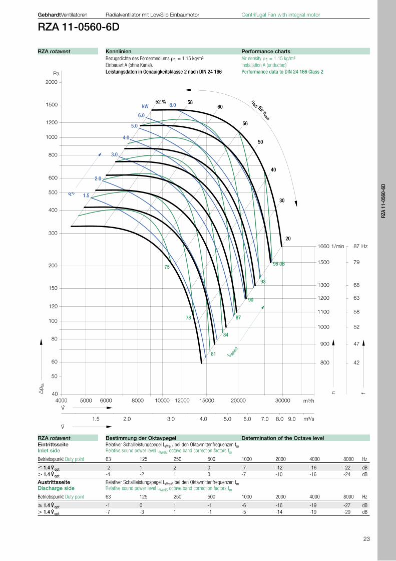
50
53 % 5961
40
58
20
81
84
87
72
78
75
L WA6;7
93 dB
90
P S
3.0
2.0
1.0
4.0
5.0kW
1.5
GebhardtVentilatoren Radialventilator mit LowSlip Einbaumotor Centrifugal Fan with integral motor
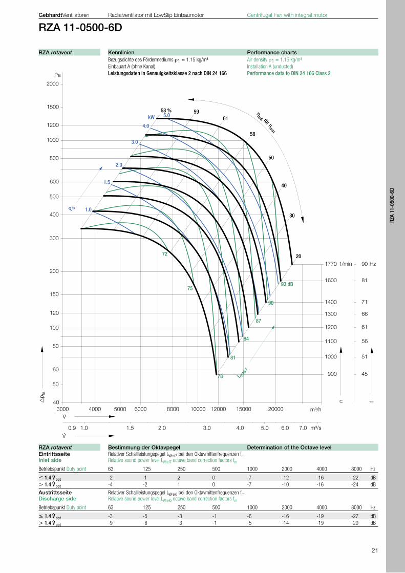
RZA 11-0500-6D
Bezugsdichte des Fördermediums ρ1 = 1.15 kg/m³ Air density ρ1 = 1.15 kg/m³ Einbauart A (ohne Kanal). Installation A (unducted) Leistungsdaten in Genauigkeitsklasse 2 nach DIN 24 166 Performance data to DIN 24 166 Class 2
Eintrittsseite Relativer Schallleistungspegel LWrel7 bei den Oktavmittenfrequenzen fm Inlet side Relative sound power level LWrel7 octave band correction factors fm
Betriebspunkt Duty point 63 125 250 500 1000 2000 4000 8000 Hz
1.4 V. opt -2 1 2 0 -7 -12 -16 -22 dB
1.4 V. opt -4 -2 1 0 -7 -10 -16 -24 dB
Austrittsseite Relativer Schallleistungspegel LWrel6 bei den Oktavmittenfrequenzen fm Discharge side Relative sound power level LWrel6 octave band correction factors fm
Betriebspunkt Duty point 63 125 250 500 1000 2000 4000 8000 Hz
1.4 V. opt -3 -5 -3 -1 -6 -16 -19 -27 dB
1.4 V. opt -9 -8 -3 -1 -5 -14 -19 -29 dB
Kennlinien Performance chartsRZA rotavent
Bestimmung der Oktavpegel Determination of the Octave levelRZA rotavent

22
914
59512409
1044
600500
59
5962
0
1071
431
247
130
805756
14
7
85
751
7
12
6 x
112
462
12
7
15
35 421
400
LG 0 LG 90 LG 180 LG 270 RD 0 RD 90 RD 180 RD 270
GebhardtVentilatoren Radialventilator mit LowSlip Einbaumotor Centrifugal Fan with integral motor
RZA 11-0560-6D
für den Betrieb mit Frequenzumrichter for opperation with Frequency inverter Motoranschluss im Dreieck () Motor in Delta Connection () Nenn- Nenn- Nennleistung Max. Leistungs- Max. Aus- Max. Betriebs- Max. Max. Fördermed. Schwingungs- Gewicht spannung frequenz Motor aufnahme Syst. gangsstrom FU frequenz Drehzahl temperatur dämpfer Nominal Nominal Nominal Max. system Max. output Max. running Max. Max. operating Anti vibration Fan supply frequency motor power input power current FC frequency Speed temperature mounts weitghtRZA 11- V Hz kW kW A Hz 1/min °C 4 × ZBD kg
0560-6D 400, 3~ 87 9.2 10.9 21.2 87 1660 40 03-0806 154
für direkten Betrieb am 60 Hz Netz - Motoranschluss im Stern (Y)for opperation at 60 Hz Mains - Motor in Star Connection (Y) Nenn- Netz- Max. Leistungs- Nennstrom Nenn- spannung frequenz aufnahme Motor Drehzahl Nominal Main- Max. input Nominal Nominal supply frequency power current speedRZA 11- V Hz kW A 1/min
0560-6D 460, 3~ 60 3.7 9.2 1160
für direkten Betrieb am 50 Hz Netz - Motoranschluss im Stern (Y)for opperation at 50 Hz Mains - Motor in Star Connection (Y) Nenn- Netz- Max. Leistungs- Nennstrom Nenn- spannung frequenz aufnahme Motor Drehzahl Nominal Main- Max. input Nominal Nominal supply frequency power current speedRZA 11- V Hz kW A 1/min
0560-6D 400, 3~ 50 2.3 9.1 980
Im Gegenuhrzeigersinn linksdrehend, Symbol LGLeft handing for anti-clockwise, symbol LG
Der Drehsinn wird durch Blickrichtung von der Anschlussseite bestimmt.
The handing can be determined through viewing from the terminal box connection.
Im Uhrzeigersinn rechtsdrehend, Symbol RD Right handing for clockwise, symbol RD
Folgende Einstellungen sind für den Betrieb des Ventilators am Frequenzumrichter vorzunehmen:- Die Eckfrequenz ist auf 87 Hz zu erhöhen, d. h. die
Ausgangsspannung von 400 V darf erst bei 87 Hz er-reicht werden.
- Die Spannungs-Frequenz-Kennlinie muss einen quadratischen Verlauf aufweisen, um die angege-benen Teillastwirkungs grade zu erreichen.
Die Parametrierung der im Katalog zugeordneten Frequenzumrichter ist dem technischen Datenblatt im Zubehörteil zu entnehmen.
Berechnungs Formeln Calculations formula
pfa · V. PS =
ηfaS
PS in Wpfa in PaV. in m³/h
LWokt7=LWA6/7+LWrel7 LWokt6=LWA6/7+LWrel6
The following curves show the fans operating with fre-quency control:- The nominal frequency of the inverter is 87 Hz, i.e.
the input frequency 400 V is increased to 87 Hz.- The performance curves plot speed/frequency
against volume and pressure, and the total efficiency (η inverter x η motor x η impeller) is expressed as a parabola.
The set up parameters for each inverter are provided in the accompanying literature.
ZKF 15- ZKE 15- ZSG 03-
Technische Daten Technical DataRZA rotavent
Technische Daten | Technical Data Technische Daten | Technical Data
Parametrierung des Frequenzumrichters Frequency Inverter ParametersRZA rotavent
Abmessungen in mm, Änderungen vorbehalten Dimensions in mm, subjekt to changeRZA rotavent
23
RZA
11-0
560-
6D
2000
1000
600
400
200
100
40
Pa
500
300
800
60
50
80
1500
150
1200
120
4000 m³/h
�p f
a
5000 6000 8000
1660
1500
1300
1200
1100
900
n
1/min 87
79
68
63
58
f
Hz
V ·
47
m³/s
V ·
1.5 2.0
10000 12000
3.0
800 42
15000
4.0
20000
6.0 7.05.0
1000 52
30000
9.08.0
ηfaS für n
max
30
50
52 % 5860
40
56
20
81
84
87
93
78
75
L WA6;7
96 dB
90
P S
3.0
2.0
6.0
4.0
5.0
kW
1.5
8.0
GebhardtVentilatoren Radialventilator mit LowSlip Einbaumotor Centrifugal Fan with integral motor
RZA 11-0560-6D
Bezugsdichte des Fördermediums ρ1 = 1.15 kg/m³ Air density ρ1 = 1.15 kg/m³ Einbauart A (ohne Kanal). Installation A (unducted) Leistungsdaten in Genauigkeitsklasse 2 nach DIN 24 166 Performance data to DIN 24 166 Class 2
Eintrittsseite Relativer Schallleistungspegel LWrel7 bei den Oktavmittenfrequenzen fm Inlet side Relative sound power level LWrel7 octave band correction factors fm
Betriebspunkt Duty point 63 125 250 500 1000 2000 4000 8000 Hz
1.4 V. opt -2 1 2 0 -7 -12 -16 -22 dB
1.4 V. opt -4 -2 1 0 -7 -10 -16 -24 dB
Austrittsseite Relativer Schallleistungspegel LWrel6 bei den Oktavmittenfrequenzen fm Discharge side Relative sound power level LWrel6 octave band correction factors fm
Betriebspunkt Duty point 63 125 250 500 1000 2000 4000 8000 Hz
1.4 V. opt -1 0 1 -1 -6 -16 -19 -27 dB
1.4 V. opt -7 -3 1 -1 -5 -14 -19 -29 dB
Kennlinien Performance chartsRZA rotavent
Bestimmung der Oktavpegel Determination of the Octave levelRZA rotavent
24
GebhardtVentilatoren Radialventilator mit LowSlip Einbaumotor Centrifugal Fan with integral motor
Ausschreibung Specification
zweiseitig saugend mit Direktantrieb durch eingebauten LowSlip-Außenläufermotor. Gefalztes Spiralformgehäuse aus verzinktem Stahlblech, mit angeschraubten, umsetzbaren Füßen, austrittsseitig mit Anschlussflansch. Hochleistungslaufrad mit rückwärtsgekrümmten Schaufeln (bis Baugröße 0280) Hohlprofilschaufeln (ab Baugröße 0315), geschweißt und pulverbeschichtet, Austrittskante schräg zur Laufradachse. Zur Schaufelaustrittskante entgegengesetzt schräge Zunge im Ventilatoraustritt. Optimal geformte Einströmdüse für geringe Zuström-verluste. Laufrad aufgebaut auf den Rotor des Außenläufer-motors in Schutzart IP 54, vollkommen wartungsfrei, statisch und dynamisch nach DIN ISO 1940, Gütestufe G 2.5 ausgewuchtet, anschlussfertig mit Metall - Klem-menkasten. Der Motor ist wirkungsgradoptimiert und über Frequenz-umrichter drehzahlveränderbar von 0 bis 100 %, er ist schwingungsisoliert am Ventilatorgehäuse befestigt. Der Motorschutz erfolgt über serienmäßig eingebaute Kaltleiter. Netzbetrieb ist bei konstanter Drehzahl möglich. Leistungsdaten in Genauigkeitsklasse 2 nach DIN 24 166.
Ventilatortyp rotavent RZA 11- ..................
Gehäusestellung LG = ..................
Volumenstrom V. = .................. m3/h
frei ausblasende Druckerhöhung pfa = .................. Pa
Dichte im Eintritt ρ1 = .................. kg/m3
Fördermediums-Temperatur t = .................. °C
Leistungsaufnahme System PS = .................. kW
Ausgangsstrom Frequenzumrichter IA = .................. A
Systemwirkungsgrad ηfaS = ..................
Betriebsfrequenz f = .................. Hz
max. Betriebsfrequenz fmax = .................. Hz
Gewicht m = .................. kg
Zubehör und Sonderausstattungen (gegen Mehrpreis)
Anschlussflansch ZKF Anschlusstutzen ZKE Berührungsschutzgitter für die Eintrittsseite ZSG Kondenswasserablaufstutzen IBW Inspektionsdeckel IWISchwingungsdämpfer ZBD Erhöhter Korrosionsschutz SKS Volumenstrom-Messvorrichtung IMVFrequenzumrichter Paket Differenzdrucksensor EIPUniversalregelgerät ERA Revisionsschalter ESH
double inlet with direct drive through integral external rotor motor. Lap jointed scroll of galvanised sheet steel with bolt on multipositioned feet, and discharge flange connection. High performance impeller with backward curved blades, (true hollow aerofoil on sizes 0315 and above) inclined obliquely to the shaft axis, welded and coated, discharge edge is in position and painted. Throat plate inclined obliquely in opposition to blade inclination. Inlet cones matched to the impeller to reduce entry losses. Impeller fixed to the external rotor of the motor in IP 54 type protection, completely maintenance free and ready to connect, statically and dynamically balanced to DIN ISO 1940. Quality level G 2.5, ready to connect with metal terminal box. The motor efficiency is optimised with the frequency inverters, speed control going from 0 to 100 %, and the shaft vibration isolated in the fan casing. The capability of maintaining a constant operational speed. Performance data in precision class 2 according to DIN 24 166, class B according to BS 848 (1980)
Fan Type rotavent RZA 11- ..................
Housing position LG = ..................
Flow volume rate V. = .................. m3/h
free discharge pressure increase pfa = .................. Pa
Density at inlet ρ1 = .................. kg/m3
Media temperature t = .................. °C
Power consumption system PS = .................. kW
Current frequency inverter IA = .................. A
System efficiency ηfaS = ..................
Running frequency f = .................. Hz
Max running frequency fmax = .................. Hz
Weight m = .................. kg
Accessories and special equipment (additional cost)
Discharge flange ZKFDiscahrge flexible connection ZKEInlet guards ZSGCondensation drain plug IBWInspection door IWIAnti-vibration mountings ZBDIncreased corrosion protection SKSVolumeter IMV Frequency inverter unitDifference pressure sensor EIPuniversal control device ERA Isolator ESH
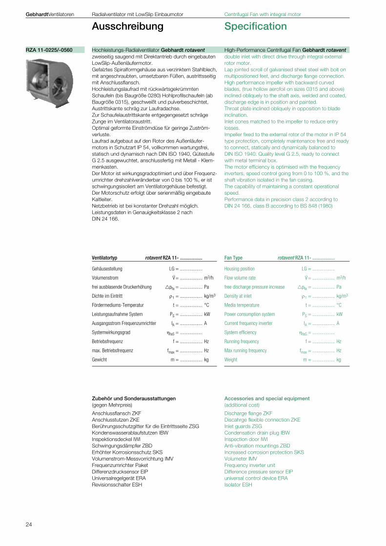
Hochleistungs-Radialventilator Gebhardt rotavent High-Performance Centrifugal Fan Gebhardt rotaventRZA 11-0225/-0560
25
Zube
hör
Acce
ssor
ies
Auss
chre
ibun
gSp
ecifi
catio
n
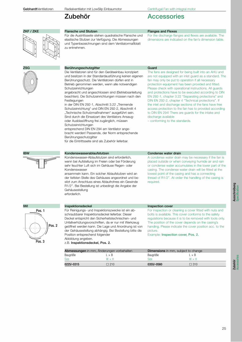
Für die Austrittsseite stehen quadratische Flansche und elastische Stutzen zur Verfügung. Die Abmessungen und Typenbezeichnungen sind dem Ventilatormaßblatt zu entnehmen.
Die Ventilatoren sind für den Geräteeinbau konzipiert und besitzen in der Standardausführung keinen eigenenBerührungsschutz. Die Ventilatoren dürfen erst in Betrieb genommen werden, wenn alle notwendigen Schutzeinrichtungenangebracht und angeschlossen sind (Betriebsanleitung beachten). Die Schutzeinrichtungen müssen nach den Festlegungenin der DIN EN 292-1, Abschnitt 3.22 „Trennende Schutzeinrichtung“ und DIN EN 292-2, Abschnitt 4 „Technische Schutzmaßnahmen“ ausgeführt sein. Sind durch die Einsatzart des Ventilators Ansaug- oder Ausblasöffnung frei zugänglich, müssen Schutzeinrichtungenentsprechend DIN EN 294 am Ventilator ange-bracht werden! Passende, der Norm entsprechende Berührungsschutzgitterfür die Eintrittsseite sind als Zubehör lieferbar.
Kondenswasser-Ablaufstutzen sind erforderlich, wenn bei Aufstellung im Freien oder bei Förderung sehr feuchter Luft sich im Gehäuse Regen- oder Kondenswasseransammeln kann. Ein solcher Ablaufstutzen wird an der tiefsten Stelle des Gehäuses angeordnet und be-sitzt zum Anschluss eines Ablaufrohres ein Gewinde R1/2’’. Bei Bestellung ist unbedingt die Angabe der Gehäusestellungerforderlich.
Für Reinigungs- und Inspektionszwecke ist ein ab-schraubbarer Inspektionsdeckel lieferbar. Dieser Deckel entspricht den Sicherheitstechnischen- und Unfallverhütungsvorschriften, da er nur mit Werkzeug geöffnet werden kann. Die Lage und Anordnung ist von der Gehäusestellung abhängig. Bei Bestellung bitte die Position entsprechend folgenderAbbildung angeben. z.B. Inspektionsdeckel, Pos. 2.
For the discharge flanges and flexes are available. The dimensions are indicated on the fan’s dimension table.
The fans are designed for being built into an AHU and are not equipped with an inlet guard as a standard. The fan may only be put to operation if all necessaryprotection equipment has been provided and fitted. Please check with operational instructions. All guards and protections have to be executed according to DIN EN 292-1, chapter 3.22 “Separating protections” and DIN EN 292-2, chapter 4 “Technical protections”. If the inlet and discharge sections of the fans have free access protection to the fan has to provided according to DIN EN 294! There are guards for the intake and discharge available– conforming to the standards.
A condense water drain may be necessary if the fan is placed outside or when conveying humide air and rain or condense water accumulates in the lower part of the casing. The condense water drain will be fitted at the lowest point of the casing and has a connectingthread of R1/2’’. At order the handling of the casing is required.
For inspection or cleaning a cover fitted with nuts and bolts is available. This cover conforms to the safety regulations because it is to be removed with tools only. The position of the cover depends on the casing’s handing. Please indicate the cover position acc. to the picture. Example: Inspection cover, Pos. 2.
GebhardtVentilatoren Radialventilator mit LowSlip Einbaumotor Centrifugal Fan with integral motor
Zubehör Accessories
Baugröße L × B Baugröße L × B Size W × H Size W × H
0225/-0315 210 0355/-0560 310
Flansche und Stutzen Flanges and FlexesZKF / ZKE
Berührungsschutzgitter GuardZSG
Kondenswasserablaufstutzen Condense water drainIBW
Inspektionsdeckel Inspection coverIWI
Abmessungen in mm, Änderungen vorbehalten Dimensions in mm, subject to change
26
H
G
EF
A
K
GebhardtVentilatoren Radialventilator mit LowSlip Einbaumotor Centrifugal Fan with integral motor
Zubehör Accessories
- Messstutzen in der Einströmdüse- Schlauchleitung zum Anschluss-
stück an der Seitenwand- Anschlussstück (Außendurchmes-
ser 6 mm) für die Druckmessung- Measuring connector in inlet cone- Hose pipe to connecting piece in
the side wall- Connecting piece (external dia-
meter of 6 mm) for the pressure measurement
With the flow measuring device it is possible to easily-measure / monitor the flow rate after the fan is installed.A pressure tapping at a predetermined position on the-inlet cone is provided whereby the differential pressure in relation to the static pressure is measured in front of the inlet cone in a static atmosphere.Permitted medium temperature +80 °C
V · = Flow rate m³/h K = Calibrating factor ρ = Gas density kg/m³ pDü = Differential pressure at cone Pa
In order to calculate the flow rate, a calibrating factor K is required. This factor is determined by comparative measurement on a standard test rig.
2V · = K × — × pDü ρ
Mit der Volumenstrom-Messvorrichtung ist eine einfache Volumenstrombestimmung und -überwachung des Ven-tilators im Einbauzustand möglich. Über eine Druckmessstelle in der Einströmdüse wird der Differenzdruck zum statischen Druck in ruhender Atmosphäre vor der Einströmdüse gemessen.Dieser Differenzdruck steht in einer festen Beziehung zum Volumenstrom.Zulässige Fördermediumstemperatur +80 °C
V · = Volumenstrom m³/h K = Kalibrierfaktor m²s/h ρ = Gasdichte kg/m³ pDü = Differenzdruck Düse Pa
Zur Berechnung des Volumenstromes wird ein Kalibrier-faktor K für den jeweiligen Ventilator benötigt, der durch eine Vergleichsmessung auf einem Normprüfstand bei ungestörter Zuströmung ermittelt wird.
2V · = K × — × pDü ρ
AV mounts are designed to prevent noise and vibrations being transmitted through the base of the fan.
AV mounts should be mounted beneath the fan base frame so the weight and spring deflections are evenly distributed. They should not be mounted symmetrically around the centre of gravity of the system when idle, because a counter force is induced into the system by the pressure created by the working fan.
It is difficult for the manufacturer to establish the positi-on of the AV mounts to suit all types of application.
Vibration and noise insulation can also be improved by ensuring that the fan is connected to its external envi-ronment by a flexible coupling.
Rubber buffers, for both vibration and noise insulation at fan speeds above 1400 rpm or 850 rpm.Rubber buffers, for noise insulation only at fan speeds under 800 rpm or 1700 rpm.
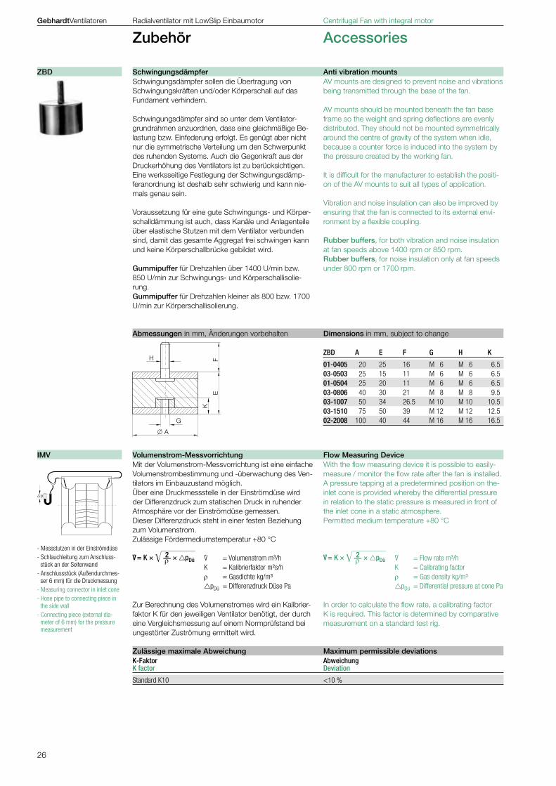
Schwingungsdämpfer sollen die Übertragung von Schwingungskräften und/oder Körperschall auf das Fundament verhindern.
Schwingungsdämpfer sind so unter dem Ventilator-grundrahmen anzuordnen, dass eine gleichmäßige Be-lastung bzw. Einfederung erfolgt. Es genügt aber nicht nur die symmetrische Verteilung um den Schwerpunkt des ruhenden Systems. Auch die Gegenkraft aus der Druckerhöhung des Ventilators ist zu berücksichtigen.Eine werksseitige Festlegung der Schwingungsdämp-feranordnung ist deshalb sehr schwierig und kann nie-mals genau sein.
Voraussetzung für eine gute Schwingungs- und Körper-schalldämmung ist auch, dass Kanäle und Anlagenteile über elastische Stutzen mit dem Ventilator verbunden sind, damit das gesamte Aggregat frei schwingen kann und keine Körperschallbrücke gebildet wird.
Gummipuffer für Drehzahlen über 1400 U/min bzw. 850 U/min zur Schwingungs- und Körperschallisolie-rung.Gummipuffer für Drehzahlen kleiner als 800 bzw. 1700 U/min zur Körperschallisolierung.
ZBD A E F G H K
01-0405 20 25 16 M 6 M 6 6.503-0503 25 15 11 M 6 M 6 6.501-0504 25 20 11 M 6 M 6 6.503-0806 40 30 21 M 8 M 8 9.503-1007 50 34 26.5 M 10 M 10 10.503-1510 75 50 39 M 12 M 12 12.502-2008 100 40 44 M 16 M 16 16.5
K-Faktor Abweichung K factor Deviation
Standard K10 <10 %
Volumenstrom-Messvorrichtung Flow Measuring Device IMV
ZBD Schwingungsdämpfer Anti vibration mounts
Zulässige maximale Abweichung Maximum permissible deviations
Abmessungen in mm, Änderungen vorbehalten Dimensions in mm, subject to change
27
Zube
hör
Acce
ssor
ies
0
4000
8000
12000
16000
20000
24000
28000
0 1000 2000�pDü Pa
0280031503550400
0450
0500m³/h
V.
p
– +
pDü
GebhardtVentilatoren Radialventilator mit LowSlip Einbaumotor Centrifugal Fan with integral motor
Zubehör Accessories
Mit dem dargestellten Diagramm und einem gemes-senen Differenzdruck an der Düse kann der Volumen-strom bei der angegebenen Dichte bestimmt werden. Das Diagramm kann auch zur Bestimmung des benö-tigten Druckbereiches eines Manometers verwendet werden. Dazu wird der Differenzdruck an der Düse für den maximal auftretenden Volumenstrom mit dem Diagramm ermittelt.
K10, s = 1.07 × K10
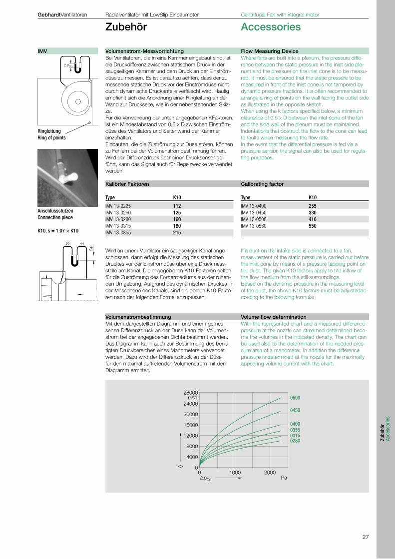
RingleitungRing of points
AnschlussstutzenConnection piece
If a duct on the intake side is connected to a fan, measurement of the static pressure is carried out before the inlet cone by means of a pressure tapping point on the duct. The given K10 factors apply to the inflow of the flow medium from the still surroundings. Based on the dynamic pressure in the measuring level of the duct, the above K10 factors must be adjustedac-cording to the following formula:
Wird an einem Ventilator ein saugseitiger Kanal ange-schlossen, dann erfolgt die Messung des statischen Druckes vor der Einströmdüse über eine Druckmess-stelle am Kanal. Die angegebenen K10-Faktoren gelten für die Zuströmung des Fördermediums aus der ruhen-den Umgebung. Aufgrund des dynamischen Druckes in der Messebene des Kanals, sind die obigen K10-Fakto-ren nach der folgenden Formel anzupassen:
Type K10
IMV 13-0225 112 IMV 13-0250 125 IMV 13-0280 160 IMV 13-0315 180 IMV 13-0355 215
Type K10
IMV 13-0400 255 IMV 13-0450 330 IMV 13-0500 410 IMV 13-0560 550
Where fans are built into a plenum, the pressure diffe-rence between the static pressure in the inlet side ple-num and the pressure on the inlet cone is to be measu-red. It must be ensured that the static pressure to be measured in front of the inlet cone is not tampered by dynamic pressure fractions. It is often recommended to arrange a ring of points on the wall facing the outlet side as illustrated in the opposite sketch. When using the k factors specified below, a minimum clearance of 0.5 x D between the inlet cone of the fan and the side wall of the plenum must be maintained. Indentations that obstruct the flow to the cone can lead to faults when measuring the flow rate. In the event that the differential pressure is fed via a pressure sensor, the signal can also be used for regula-ting purposes.
Bei Ventilatoren, die in eine Kammer eingebaut sind, ist die Druckdifferenz zwischen statischem Druck in der saugseitigen Kammer und dem Druck an der Einström-düse zu messen. Es ist darauf zu achten, dass der zu messende statische Druck vor der Einströmdüse nicht durch dynamische Druckanteile verfälscht wird. Häufig empfiehlt sich die Anordnung einer Ringleitung an der Wand zur Druckseite, wie in der nebenstehenden Skiz-ze. Für die Verwendung der unten angegebenen KFaktoren,ist ein Mindestabstand von 0,5 x D zwischen Einström-düse des Ventilators und Seitenwand der Kammer einzuhalten.Einbauten, die die Zuströmung zur Düse stören, können zu Fehlern bei der Volumenstrombestimmung führen.Wird der Differenzdruck über einen Drucksensor ge-führt, kann das Signal auch für Regelzwecke verwendet werden.
With the represented chart and a measured difference pressure at the nozzle can streamed determined beco-me the volumes in the indicated density. The chart can be used also to the determination of the needed pres-sure area of a manometer. In addition the difference pressure is determined at the nozzle for the maximally appearing volume current with the chart.
IMV Volumenstrom-Messvorrichtung Flow Measuring Device
Kalibrier Faktoren Calibrating factor
Volumenstrombestimmung Volume flow determination
28
++ ~
- = ~
pp
⊥
70
4,5
ca. 5
00
50
8ø5
16
Druckanschlüsse SpannungsversorgungPressure connections Voltage supply Ø5 mm 15...30 V DC 24 V AC ±10 %
braun brown
gelb yellow Ausgang Output 0 ... 10V DC weiss white
GebhardtVentilatoren Radialventilator mit LowSlip Einbaumotor Centrifugal Fan with integral motor
Zubehör Accessories
Sensor mit Membranmesswerk zur Messwertübertragung von Druck, Unterdruck oder Differenzdruck nicht aggressiver Gase.
Ausführung Der zu messende Differenzdruck wird intern elektronisch in ein proportionales Ausgangssignal von 0...10V umgeformt.
Anwendungsbereiche Volumenstromregelung bei Radialventilatoren (mit Volumenstrom-Messvorrichtung IMV) in Verbindung mit Frequenzumrichtern der Typen G110, MM420, MM430, bzw. einem Universalregelgerät Typ ERA 02-4000-5E in Verbindung mit einem Frequenzumrichter
Elektrischer Anschluss und Montage Der Differenzdrucksensor liefert ein Ausgangssignal (0-10 V), bei Druckanstieg am “Plus” -Anschluss gegenüber Druck am “Minus”-Anschluss. Spannungsversorgung: 15-30 V DC oder 24 V AC, ±15 %. Druckanschlüsse müssen senkrecht nach unten zeigen, Schlauchtüllen ø5 mm.
Messbereich Schutzart max. Überlast Ausgangssignal Betriebs- Stromaufnahme Sicherheit proportional temperatur Measuring Protection max. current Overload Output signal Operating range type consumption protection proportional temperatureEIP Pa ca. mA Pa V DC °C
20 0 - 200 IP65 12 20000 0-10 0 bis +5021 0 - 500 IP65 12 20000 0-10 0 bis +5022 0 - 1000 IP65 12 20000 0-10 0 bis +5023 0 - 2000 IP65 12 20000 0-10 0 bis +5024 0 - 4000 IP65 12 20000 0-10 0 bis +50
Nullpunktabweichung: ±0.75 % Summe von Linearität und Hysterese: ±1 %Temperaturdrift Nullpunkt: ±0.3 % / 10 K Temperaturdrift Messspanne: ±0.2 % / 10 K
Sensor with membrane for measuring the pressure, negative pressure or differential pressure of nonaggressive gases.
Type The differential pressure to be measured acts transformed into an output signal of 0...10V by electronics (in SMD technology).
Application ranges Pressure regulators for central ventilation systems and variable volume systems of built-in air conditioning (BMS) e.g. in connection with pressure regulator appli-ances type EPA 83/82, ERA 02-4000-5E Volume flow regulators in centrifugal fans (with volume flow measuring device IMV) in connection with a fre-quency inverter type EFE53/73, or a universal regulator appliance type ERA 02-4000-5E in connection with a frequency regulator
Electrical connection and installation The differential pressure sensor delivers a starting signal (0-10 V) by pressure increase at the ”Plus” connection opposite pressure on the ”Minus” connection. Voltage supply: 15-30 V DC or 24 V AC, ±15 %. Pressure connections must point downward, tube connection ø5 mm.
Null drift: ±0.75 % Sum of linearity and hysteresis: ±1 %Temperature drift zero point: ±0.3 % / 10 K Temperature drift length of measurement: ±0.2 % / 10 K
Differential pressure sensor
Abmessungen in mm. Änderungen vorbehalten Dimensions in mm, Subject to change
Technische Daten Technical Data
Anschlussplan Connection diagram
Messgenauigkeit
Measuring accuracy
EIP Differenzdrucksensor
29
Zube
hör
Acce
ssor
ies
GebhardtVentilatoren Radialventilator mit LowSlip Einbaumotor Centrifugal Fan with integral motor
Zubehör Accessories
AusführungFrequenzumrichter mit variabler Ausgangsspannung und -frequenz, optimal abgestimmt auf den Betrieb von Radialventilatoren mit Asynchronmotoren. Durch den Einsatz von modernen Leistungshalbleitern ist eine Drehzahleinstellung mit hohem Wirkungsgrad gewährleistet.
Taktfrequenzen sind bei allen Typen bis 16kHz ein-stellbar. Falls höchste Taktfrequenzen benötigt werden (beispielsweise aus Geräuschgründen), reduziert sich der maximale Ausgangsstrom, wofür die Leistungs-zuordnung speziell zu überprüfen ist. Das Gesamtpaket umfasst Frequenzumrichter, Filter für Klasse B (für Wohn- und Geschäftsbereich) sowie ein Bedienfeld.
Allgemeine LeistungsmerkmaleMotorschutzfunktion für Motoren mit Kaltleiter-Temperaturfühler, Einstellmöglichkeiten für Hoch- und Tieflauframpen, minimale und maximale Drehzahl, Fixdrehzahlen, Fangschaltung auf laufenden Betrieb, programmierbare Eingänge und PI-Regler (nur bei MM420 und MM430), serielle Schnittstelle RS 485 sowie ausführliche Betriebsanleitung.Vorsicht bei Kombination mit Revisionsschalter (ESH)!Gegebenenfalls sind hierbei gesonderte EMV-Maßnahmen erforderlich; zudem Schalter niemals im stromführenden Zustand schalten, entstehen-de Überspannungen können den Schalter und die Wicklung gefährden!
Leistungsbereich G110 1AC 230V (für Einphasen-Wechselstrom-Netz)0.25 bis 2.2 kW Motornennleistung, 200 bis 240V ±10% Einphasen-Wechselstrom, 47 bis 63Hz, Drehstromausgang 3 × 230V AC, Schutzart IP 20. Zulässige Umgebungstemperatur bei Betrieb: -10°C bis +40°C.
Leistungsbereich MM420 3AC 400V (für Drehstrom-Netz) 0.55 bis 11kW Motornennleistung, 380 bis 480V ±10% Drehstrom, 47 bis 63Hz, Drehstromausgang 3 × 400V AC, Schutzart IP 20, Zulässige Umgebungstemperatur bei Betrieb: -10°C bis +50°C. Der zur Einhaltung der Funkentstörung nach EMV-Fach-Grundnorm EN 50081-1 (Wohn- und Geschäftsbereich) notwendige Funkentstörfilter ist im Paket als Unterbauvariante Integriert. Netzdrossel zur Erfüllung der EN 61000-3-2 als Zusatzkomponente. Leistungsreduktion bei der Verwendung hoher Taktfrequenzen beachten!
Leistungsbereich MM430 3AC 400V (für Drehstrom-Netz) 15 bis 250kW Motornennleistung, 380 bis 480V ±10% Drehstrom, 47 bis 63Hz, Drehstromausgang 3 x 400V AC, Schutzart IP 20, Zulässige Umgebungstemperatur bei Betrieb: -10°C bis +50°C. Der zur Einhaltung der Funkentstörung nach EMV-Fach-Grundnorm EN 50081-1 (Industrieanwendungen) notwendige Funkentstörfilter ist teilweise integriert. Um EMV-Anforderungen Klasse B zu erreichen, ist ein Frequenzumrichter ohne Filter auszuwäh-len. Der entsprechende EMV-B Filter ist dann als Zusatzkomponente erforderlich. Leistungsreduktion bei der Verwendung hoher Taktfrequenzen beachten!
G110
MM420
DesignFrequency inverter with variable output voltage and frequency, specially designed for the operation of cen-trifugal fans with induption motors. Due to the use of modern power semiconductors it is possible to achieve a speed of revolution with high efficiency. Switching frequencies up to 16 kHz can be set with all types. If the highest switching frequencies are required (for example for reasons of noise reduction), the ma-ximum output current is decreased, in which case the performance category should be specially checked. The overall package includes the frequency inver-ter, filter for class B (for residential and commercial uses) as well as a control unit.
General Performance characteristics Motor protection feature for motors with thermistor temperature sensors, adjustable accelaration and deaccelaration ramps, minimum and maximum rotation speeds, fixed rotation speeds, trapping switch during operation, programmable inputs and PI-controller (MM420 and MM430 only), RS 485 serial interface as well as a detailed operating instructions. Caution about combination with isolators (ESH)!Special EMC-action can be necessary, furthermore do not switch during operation, overvoltages can destroy the switch and the motor-winding.
Performance range G110 1AC 230V (for single-phase AC supply)0.25 to 2.2 kW rated motor power, 200 to 240 V ±10 % single-phase AC, 47 to 63 Hz, three-phase cur-rent output 3 × 230 V AC, protection class IP 20. Permitted ambient temperature during operation: -10 °C to +40 °C.
Performance range MM420 3AC 400V (for three-phase AC supply)0.55 to 11 kW rated motor power, 380 to 480 V ±10 % three-phase AC, 47 to 63 Hz, three-phase current output 3 × 400V AC, protection class IP 20. Permitted ambient temperature during operation: -10 °C to +50 °C. The interference suppression filter required to comply with the EMC basic interference suppression standard EN 50081-1 (residential and commercial uses) is integrated into the package as substructure option. Power choke to comply with EN 61000-3-2 as additional component. Observe performance reduction when using high clock frequencies!
Performance range MM430 3AC 400V (for three-phase AC supply)15 to 250 kW rated motor power, 380 to 480 V ±10 % three-phase AC, 47 to 63Hz, three-phase current out-put 3 x 400V AC, protection class IP 20. Permitted ambient temperature during operation: -10 °C to +50 °C. The interference suppression filter required to comply with the EMC basic interference suppression standard EN 50081-1 (industrial appli-cations) is partially integrated. In order to attain EMC requirements Class B a frequency inverter without filter should be selected. The appropriate EMC-B filter is then required as an additional component. Observe performance reduction when using high clock frequencies!
G110 / MM420 / MM430 Frequenzumrichter Frequency inverter
30
GebhardtVentilatoren Radialventilator mit LowSlip Einbaumotor Centrifugal Fan with integral motor
Zubehör Accessories
Zusatzkomponenten Accessories Paket Nennstrom Nennleistung Frequenzumrichter Filter A Bedienfeld Filter B NetzdrosselUnit Nominal current Nominal power Frequency inverter Filter class A Control panel Filter class B Line choke 6SE6400-* MM430 3AC 400V A (4kHz) kW 6SL3000- 6SE6400- 6SL3255- 6SE6400- 6SL3000-°
32.00 15.0 2AD31-5CA0 integriert | integrates 0BE00-0AA0 2FS03-8CD0 *3CC03-5CD3 38.00 18.5 2AD31-8DA0 integriert | integrates 0BE00-0AA0 *** *3CC04-4DD0 45.00 22.0 2AD32-2DA0 integriert | integrates 0BE00-0AA0 *** *3CC04-4DD0 62.00 30.0 2AD33-0DA0 integriert | integrates 0BE00-0AA0 *** *3CC05-2DD0 75.00 37.0 2AD33-7EA0 integriert | integrates 0BE00-0AA0 *** *3CC08-3ED0 90.00 45.0 2AD34-5EA0 integriert | integrates 0BE00-0AA0 *** *3CC08-3ED0 110.00 55.0 2AD35-5FA0 integriert | integrates 0BE00-0AA0 *** *3CC11-2FD0 145.00 75.0 2AD37-5FA0 integriert | integrates 0BE00-0AA0 *** *3CC11-2FD0 178.00 90.0 2AD38-8FA0 integriert | integrates 0BE00-0AA0 *** *3CC11-7FD0 180.40 110.0 2UD41-1FA0 0BE32-5AA0 0BE00-0AA0 – °0CE32-3AA0 220.00 132.0 2UD41-3FA0 0BE34-4AA0 0BE00-0AA0 – °0CE32-8AA0 265.80 160.0 2UD41-6GA0 0BE34-4AA0 0BE00-0AA0 – °0CE33-3AA0 325.60 200.0 2UD42-0GA0 0BE34-4AA0 0BE00-0AA0 – °0CE35-1AA0 419.80 250.0 2UD42-5GA0 0BE36-0AA0 0BE00-0AA0 – °0CE35-1AA0
Die angegebenen Nennleistungen der Geräte sind „Herstellerangaben, welche zur Grobauswahl dienen“. Die genaue Zuordnung der Frequenzumrichter erfolgt über die zulässige Strombelastung im vorliegenden Katalog für eine Pulsfrequenz von 4 kHz. Dabei ist zu beachten, dass für eventuell erforderliche höhere Taktfrequenzen, die Stromabgabe des FUs sinkt, d.h. ein größerer FU notwendig wird. Ebenso können lange Leitungen und zusätzliche Filter die Zuordnung eines größeren Frequezumrichters erfordern.
The indicated ratings of the units are made for a quick selection. The exact dedication of an inverter in this catalogue is made by taking into account of the max. admitted current at a pulse frequency of 4kHz. It is important to know that at higher pulse frequencies the supplied current of the inverter will be decreasing, with the possible consequences of having to select a larger inverter unit. Also longer feed lines or additional radio frequency filters may lead to the choice of a larger in-verter size.
im Paket enthaltene Komponenten Zusatzkomponenten Parts of the unit Accessories Paket Nennstrom Nennleistung Frequenzumrichter Filter B Bedienfeld NetzdrosselUnit Nominal current Nominal power Frequency inverter Filter class B Control panel Line chokeG110 1AC 230V A (4kHz/+40°C) kW 6SL3211- 6SE6400- 6SL3255- 6SE6400-
0.25KW EMV B 1.70 0.25 0AB12-5BA0 integriert | integrates 0AA00-4BA0 3CC00-4AB3 0.37KW EMV B 2.30 0.37 0AB13-7BA0 integriert | integrates 0AA00-4BA0 3CC01-0AB3 0.55KW EMV B 3.20 0.55 0AB15-5BA0 integriert | integrates 0AA00-4BA0 3CC01-0AB3 0.75KW EMV B 3.90 0.75 0AB17-5BA0 integriert | integrates 0AA00-4BA0 3CC01-0AB3 1.10KW EMV B 6.00 1.10 0AB21-1AA0 integriert | integrates 0AA00-4BA0 3CC02-6BB3 1.50KW EMV B 7.80 1.50 0AB21-5AA0 integriert | integrates 0AA00-4BA0 3CC02-6BB3 2.20KW EMV B 11.00 2.20 0AB22-2AA0 integriert | integrates 0AA00-4BA0 3CC02-6BB3
im Paket enthaltene Komponenten Zusatzkomponenten Parts of the unit Accessories Paket Nennstrom Nennleistung Frequenzumrichter Filter B Bedienfeld NetzdrosselUnit Nominal current Nominal power Frequency inverter Filter class B Control panel Line chokeMM420 3AC 400V A (4kHz) kW 6SE6400- 6SE6400- 6SL3255- 6SE6400-
0.55KW EMV B 1.60 0.55 2UD15-5AA1 2FB00-6AD0 0BP00-0AA0 3CC00-2AD3 0.75KW EMV B 2.10 0.75 2UD17-5AA1 2FB00-6AD0 0BP00-0AA0 3CC00-4AD3 1.10KW EMV B 3.00 1.10 2UD21-1AA1 2FB00-6AD0 0BP00-0AA0 3CC00-4AD3 1.50KW EMV B 4.00 1.50 2UD21-5AA1 2FB00-6AD0 0BP00-0AA0 3CC00-6AD3 2.20KW EMV B 5.90 2.20 2AD22-2BA1 2FS01-6BD0 0BP00-0AA0 3CC01-0BD3 3.00KW EMV B 7.70 3.00 2AD23-0BA1 2FS01-6BD0 0BP00-0AA0 3CC01-0BD3 4.00KW EMV B 10.20 4.00 2AD24-0BA1 2FS01-6BD0 0BP00-0AA0 3CC01-4BD3 5.50KW EMV B 13.20 5.50 2AD25-5CA1 2FS03-8CD0 0BP00-0AA0 3CC02-2CD3 7.50KW EMV B 18.40 7.50 2AD27-5CA1 2FS03-8CD0 0BP00-0AA0 3CC02-2CD3 11.0KW EMV B 26.00 11.00 2AD31-1CA0 2FS03-8CD0 0BP00-0AA0 3CC03-5CD3
Frequency inverter
für Drehstrommotoren am Drehstrom-Netz for three-phase AC motors on the three-phase supply (3~ gespeist) MICROMASTER** 430 (3~ power) MICROMASTER** 430
für Drehstrommotoren am Wechselstrom-Netz for three-phase AC motors on the single-phase supply (1~ gespeist) SINAMICS** G110 (1~ power) SINAMICS** G110
für Drehstrommotoren am Drehstrom-Netz for three-phase AC motors on the three-phase supply (3~ gespeist) MICROMASTER** 420 (3~ power) MICROMASTER** 420
G110 Technische Daten Technical Data
MM420 Technische Daten Technical Data
MM430 Technische Daten Technical Data
G110 / MM420 / MM430 Frequenzumrichter
31
Zube
hör
Acce
ssor
ies
b
a
c
b
a
c
b
a
c
GebhardtVentilatoren Radialventilator mit LowSlip Einbaumotor Centrifugal Fan with integral motor
Zubehör Accessories
** SINAMICS und MICROMASTER sind eingetragene Warenzeichen der SIEMENS AG
*** Um EMV-Anforderungen Klasse B zu erreichen, ist ein Frequenzumrichter ohne Filter auszuwählen. Der entsprechende EMV-B Filter ist dann zusätzlich erforderlich.
** SINAMICS and MICROMASTER are registered trademarks of SIEMENS AG
*** In order to comply with EMC requirements class B, a frequency inverter without filter should be chosen. The appropriate EMC-B filter is then additionally required.
Paket Frequenzumrichter Nennleistung GewichtUnit Frequency inverter Nominal power Weight MM430 3AC 400V 6SE6430- kW a b c kg
– 2AD31-5CA0 15.0 245 185 195 5.7– 2AD31-8DA0 18.5 520 275 245 17– 2AD32-2DA0 22.0 520 275 245 17– 2AD33-0DA0 30.0 520 275 245 17– 2AD33-7EA0 37.0 650 275 245 22– 2AD34-5EA0 45.0 650 275 245 22– 2AD35-5FA0 55.0 1150 350 320 75– 2AD37-5FA0 75.0 1150 350 320 75– 2AD38-8FA0 90.0 1150 350 320 75– 2UD41-1FA0 110.0 1450 326 356 116– 2UD41-3FA0 132.0 1450 326 356 116– 2UD41-6GA0 160.0 1533 326 545 176– 2UD42-0GA0 200.0 1533 326 545 176– 2UD42-5GA0 250.0 1533 326 545 176
Paket Frequenzumrichter Nennleistung GewichtUnit Frequency inverter Nominal power WeightG110 1AC 230V 6SL3211- kW a b c kg
0.25KW EMV B 0AB12-5BA0 0.25 150 90 116 0.80.37KW EMV B 0AB13-7BA0 0.37 150 90 116 0.80.55KW EMV B 0AB15-5BA0 0.55 150 90 131 0.90.75KW EMV B 0AB17-5BA0 0.75 150 90 131 0.91.10KW EMV B 0AB21-1AA0 1.10 160 140 142 1.51.50KW EMV B 0AB21-5AA0 1.50 160 140 142 1.52.20KW EMV B 0AB22-2AA0 2.20 181 184 152 2.1
Paket Frequenzumrichter Nennleistung GewichtUnit Frequency inverter Nominal power WeightMM420 3AC 400V 6SE6420- kW a b c kg
0.55KW EMV B 2UD15-5AA1 0.55 173 73 149 1.00.75KW EMV B 2UD17-5AA1 0.75 173 73 149 1.01.10KW EMV B 2UD21-1AA1 1.10 173 73 149 1.01.50KW EMV B 2UD21-5AA1 1.50 173 73 149 1.02.20KW EMV B 2AD22-2BA1 2.20 202 149 172 3.33.00KW EMV B 2AD23-0BA1 3.00 202 149 172 3.34.00KW EMV B 2AD24-0BA1 4.00 202 149 172 3.35.50KW EMV B 2AD25-5CA1 5.50 245 185 195 5.07.50KW EMV B 2AD27-5CA1 7.50 245 185 195 5.011.0KW EMV B 2AD31-1CA0 11.00 245 185 195 5.0
Frequency inverter
für Drehstrommotoren am Drehstrom-Netz for three-phase AC motors on the three-phase supply (3~ gespeist) MICROMASTER** 430 (3~ power) MICROMASTER** 430
für Drehstrommotoren am Wechselstrom-Netz for three-phase AC motors on the single-phase supply (1~ gespeist) SINAMICS** G110 (1~ power) SINAMICS** G110
für Drehstrommotoren am Drehstrom-Netz for three-phase AC motors on the three-phase supply (3~ gespeist) MICROMASTER** 420 (3~ power) MICROMASTER** 420
Abmessungen in mm. Änderungen vorbehalten Dimensions in mm, Subject to change
Abmessungen in mm. Änderungen vorbehalten Dimensions in mm, Subject to change
Abmessungen in mm. Änderungen vorbehalten Dimensions in mm, Subject to change
G110
MM420
MM430
G110 / MM420 / MM430 Frequenzumrichter
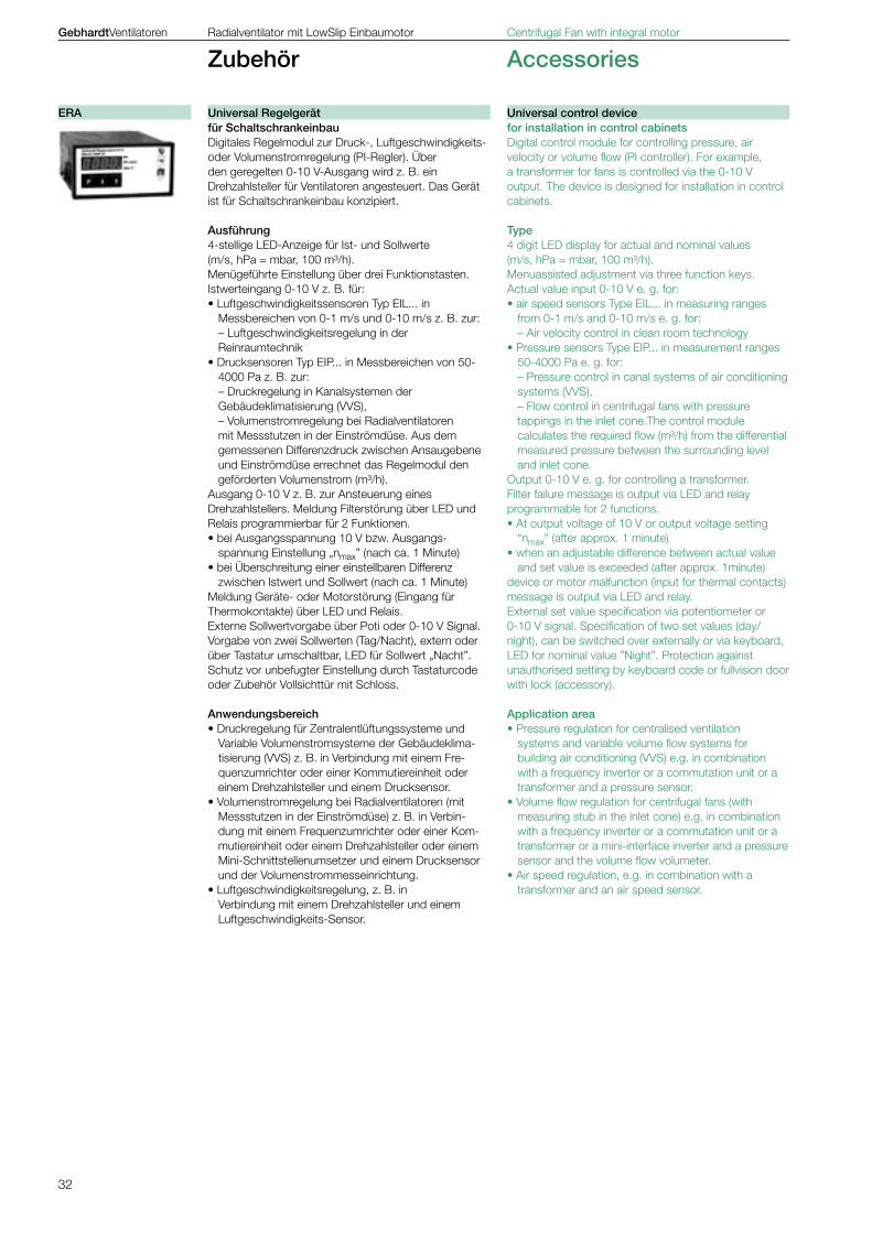
32
GebhardtVentilatoren Radialventilator mit LowSlip Einbaumotor Centrifugal Fan with integral motor
Zubehör Accessories
für Schaltschrankeinbau Digitales Regelmodul zur Druck-, Luftgeschwindigkeits- oder Volumenstromregelung (PI-Regler). Über den geregelten 0-10 V-Ausgang wird z. B. ein Drehzahlsteller für Ventilatoren angesteuert. Das Gerät ist für Schaltschrankeinbau konzipiert.
Ausführung4-stellige LED-Anzeige für Ist- und Sollwerte (m/s, hPa = mbar, 100 m³/h). Menügeführte Einstellung über drei Funktionstasten. Istwerteingang 0-10 V z. B. für:• Luftgeschwindigkeitssensoren Typ EIL... in
Messbereichen von 0-1 m/s und 0-10 m/s z. B. zur: – Luftgeschwindigkeitsregelung in der Reinraumtechnik
• Drucksensoren Typ EIP... in Messbereichen von 50-4000 Pa z. B. zur: – Druckregelung in Kanalsystemen der Gebäudeklimatisierung (VVS), – Volumenstromregelung bei Radialventilatoren mit Messstutzen in der Einströmdüse. Aus dem gemessenen Differenzdruck zwischen Ansaugebene und Einströmdüse errechnet das Regelmodul den geförderten Volumenstrom (m³/h).
Ausgang 0-10 V z. B. zur Ansteuerung eines Drehzahlstellers. Meldung Filterstörung über LED und Relais programmierbar für 2 Funktionen.• bei Ausgangsspannung 10 V bzw. Ausgangs-
spannung Einstellung „nmax” (nach ca. 1 Minute)• bei Überschreitung einer einstellbaren Differenz
zwischen Istwert und Sollwert (nach ca. 1 Minute)Meldung Geräte- oder Motorstörung (Eingang für Thermokontakte) über LED und Relais. Externe Sollwertvorgabe über Poti oder 0-10 V Signal.Vorgabe von zwei Sollwerten (Tag/Nacht), extern oder über Tastatur umschaltbar, LED für Sollwert „Nacht”. Schutz vor unbefugter Einstellung durch Tastaturcode oder Zubehör Vollsichttür mit Schloss.
Anwendungsbereich• Druckregelung für Zentralentlüftungssysteme und
Variable Volumenstromsysteme der Gebäudeklima-tisierung (VVS) z. B. in Verbindung mit einem Fre-quenzumrichter oder einer Kommutiereinheit oder einem Drehzahlsteller und einem Drucksensor.
• Volumenstromregelung bei Radialventilatoren (mit Messstutzen in der Einströmdüse) z. B. in Verbin-dung mit einem Frequenzumrichter oder einer Kom-mutiereinheit oder einem Drehzahlsteller oder einem Mini-Schnittstellenumsetzer und einem Drucksensor und der Volumenstrommesseinrichtung.
• Luftgeschwindigkeitsregelung, z. B. in Verbindung mit einem Drehzahlsteller und einem Luftgeschwindigkeits-Sensor.
for installation in control cabinets Digital control module for controlling pressure, air velocity or volume flow (PI controller). For example, a transformer for fans is controlled via the 0-10 V output. The device is designed for installation in control cabinets.
Type4 digit LED display for actual and nominal values (m/s, hPa = mbar, 100 m³/h). Menuassisted adjustment via three function keys. Actual value input 0-10 V e. g. for:• air speed sensors Type EIL... in measuring ranges
from 0-1 m/s and 0-10 m/s e. g. for: – Air velocity control in clean room technology
• Pressure sensors Type EIP... in measurement ranges 50-4000 Pa e. g. for: – Pressure control in canal systems of air conditioning systems (VVS), – Flow control in centrifugal fans with pressure tappings in the inlet cone.The control module calculates the required flow (m³/h) from the differential measured pressure between the surrounding level and inlet cone.
Output 0-10 V e. g. for controlling a transformer. Filter failure message is output via LED and relay programmable for 2 functions.• At output voltage of 10 V or output voltage setting
“nmax” (after approx. 1 minute)• when an adjustable difference between actual value
and set value is exceeded (after approx. 1minute)device or motor malfunction (input for thermal contacts) message is output via LED and relay. External set value specification via potentiometer or 0-10 V signal. Specification of two set values (day/night), can be switched over externally or via keyboard, LED for nominal value ”Night”. Protection against unauthorised setting by keyboard code or fullvision door with lock (accessory).
Application area• Pressure regulation for centralised ventilation
systems and variable volume flow systems for building air conditioning (VVS) e.g. in combination with a frequency inverter or a commutation unit or a transformer and a pressure sensor.
• Volume flow regulation for centrifugal fans (with measuring stub in the inlet cone) e.g. in combination with a frequency inverter or a commutation unit or a transformer or a mini-interface inverter and a pressure sensor and the volume flow volumeter.
• Air speed regulation, e.g. in combination with a transformer and an air speed sensor.
ERA Universal Regelgerät Universal control device
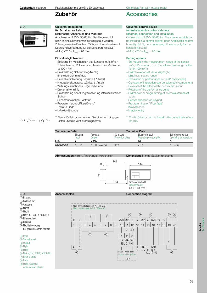
33
Zube
hör
Acce
ssor
ies
72
1448142
154
1 2 3
1 2 3 4 5 6 7 8 9 10 11 12 13 14 15 16 17 18 19 20
OUTGND+U
0 - 10 V
(Imax 10 mA)0 - 10 V0 - 10 V
GND+GND+
TKTKGNDAGND+EGND+24VNL1
NL1EIL 01/10
EIP
�����
�
��
�
GebhardtVentilatoren Radialventilator mit LowSlip Einbaumotor Centrifugal Fan with integral motor
Zubehör Accessories
für Schaltschrankeinbau Elektrischer Anschluss und MontageAnschluss an 230 V, 50/60 Hz. Das Regelmodul kann in eine Schaltschranktür eingebaut werden.Zulässige relative Feuchte: 85 %, nicht kondensierend.Spannungsversorgung für die Sensoren inklusive: +24 V, ±20 %, Imax = 70 mA.
Einstellmöglichkeiten– Sollwerte im Messbereich des Sensors (m/s, hPa =
mbar), bzw. im Volumenstrombereich des Ventilators (x 100 m³/h)
– Umschaltung Sollwert (Tag/Nacht)– Einstellbereich min/max– Parallelverschiebung Kennlinie (P-Anteil)– Integrationskonstante wählbar (I-Anteil)– Wirkungsumkehr des Regelverhaltens– Drehung Kennlinie– Umschaltung oder Programmierung interner/externer
Sollwert– Sensorauswahl per Tastatur– Programmierung „Filterstörung”– Tastatur-Code– k-Faktor-Eingabe
** Den K10-Faktor entnehmen Sie bitte den gängigen Listen unseres Ventilatorprogramms.
for installation in control cabinets Electrical connection and installationConnection to 230 V, 50/60 Hz. The control module can be installed in a control cabinet door. Admissible relative humidity: 85 %, noncondensing. Power supply for the sensors included: +24 V, ±20 %, Imax = 70 mA.
Setting options– Set values in the measurement range of the sensor
(m/s, hPa = mbar), or in the volume flow range of the fan (x 100 m³/h)
– Switch over of set value (day/night)– Min./max. setting range– Translation of performance curve (P component)– Constant of integration can be selected (I component)– Reversal of the effect of the control behaviour– Rotation of the performance curve– Switchover or programming of internal/external set
value– Sensor selection via keypad– Programming for ”Filter fault”– Keypad code– k factor entry
** The K10-factor can be found in the current lists of our fan line.
Eingang Ausgang Schutzart Eigenverbrauch Betriebstemperatur Input Output Protection class Operating consumption Operating temperatureERA V V, mA VA °C
02-4000-5E 0 ... 10 0 ...10, max. 10 IP20 < 10 0 ... +40
_ _ V · = k p = K10 2 ρ p
Eingang Sollwert ext. Ausgang Nacht Nacht Netz, 1~, 230 V, 50/60 Hz Filterwechsel Störung Nachtabsenkung
bei geschlossenem Kontakt
Input Set value ext. Output Night Night Mains, 1~, 230 V, 50/60 Hz Filter change Error Night reduction
when contact closed
braun brown
weiß white
gelb yellow
Max. Kontaktbelastung 5 A / 250 V AC Max. contact capacity 5 A / 250 V AC
EinbauausschnittInstallation cut68 × 138 mm
Abmessungen in mm. Änderungen vorbehalten Dimensions in mm, Subject to change
Technische Daten Technical Data
Anschlussplan Connection diagram ERA
ERA Universal Regelgerät Universal control device

34
GebhardtVentilatoren Radialventilator mit LowSlip Einbaumotor Centrifugal Fan with integral motor
Zubehör Accessories
AusführungSchlagfestes, graues Metallgehäuse mit schwarzem Schaltgriff, hinterlegt mit silbergrauer Platte, Schaltzei-chen 0 und I. Aufbau-Ausführung in Schutzart IP 65 bzw. IP54 (siehe Kennzeichnung in der Tabelle). Die Revisionsschalter enthalten übersichtliche An-schlussklemmen und sind mit einem Anschlussbild versehen. Alle Revisionsschalter sind mit Deckelkupplung und integrierter Sperrvorrichtung ausgestattet, teilweise ist der Drehschalter für eine Bügelschloss-Sicherung vor-gesehen. Die Revisionsschalter sind mit potentialfreien Kontakten ausgeführt: 1 Schließer und 1 Öffner. Revisionsschalter für Motoren mit eingebautem Ther-mokontakt haben grundsätzlich drei zusätzliche Hilfs-kontakte, damit bei Reinigungs- bzw. Wartungsarbeiten das vorgeschaltete Steuergerät nicht durch Motorstö-rung ausfällt. EinsatzDie Revisionsschalter ESH 22- mit Metallgehäuse werden eingesetzt, wenn eine Abschirmung gegen Störstrahlung notwendig ist, z.B. in Verbindung mit Frequenzumrichtern oder anderen Motorsteuerun-gen, die mit elektronischer Leistungsregelung aus-gerüstet sind. Achtung! Schalter niemals im stromführenden Zustand schalten, entstehende Überspannungen können den Schalter und die Wicklung gefährden! Funktion Der Revisionsschalter trennt bei Reinigungs-, Wartungs- oder Reparaturarbeiten den Ventilator -vor Ort- sicher vom Netz und vermeidet so Unfälle durch unkontrollier-tes Einschalten der Anlage durch Dritte. Dabei wird die Arbeit für das Service-Personal wesent-lich erleichtert.
AusführungSchlagfestes, graues Metallgehäuse mit schwarzem Schaltgriff, hinterlegt mit silbergrauer Platte, Schaltzei-chen 0 und I. Aufbau-Ausführung in Schutzart IP 65 bzw. IP54 (siehe Kennzeichnung in der Tabelle). Die Revisionsschalter enthalten übersichtliche An-schlussklemmen und sind mit einem Anschlussbild versehen. Alle Revisionsschalter sind mit Deckelkupplung und integrierter Sperrvorrichtung ausgestattet, teilweise ist der Drehschalter für eine Bügelschloss-Sicherung vor-gesehen. Die Revisionsschalter sind mit potentialfreien Kontakten ausgeführt: 1 Schließer und 1 Öffner. Revisionsschalter für Motoren mit eingebautem Ther-mokontakt haben grundsätzlich drei zusätzliche Hilfs-kontakte, damit bei Reinigungs- bzw. Wartungsarbeiten das vorgeschaltete Steuergerät nicht durch Motorstö-rung ausfällt. EinsatzDie Revisionsschalter ESH 22- mit Metallgehäuse werden eingesetzt, wenn eine Abschirmung gegen Störstrahlung notwendig ist, z.B. in Verbindung mit Frequenzumrichtern oder anderen Motorsteuerun-gen, die mit elektronischer Leistungsregelung aus-gerüstet sind. Achtung! Schalter niemals im stromführenden Zustand schalten, entstehende Überspannungen können den Schalter und die Wicklung gefährden! Funktion Der Revisionsschalter trennt bei Reinigungs-, Wartungs- oder Reparaturarbeiten den Ventilator -vor Ort- sicher vom Netz und vermeidet so Unfälle durch unkontrollier-tes Einschalten der Anlage durch Dritte. Dabei wird die Arbeit für das Service-Personal wesent-lich erleichtert.
Revisionsschalter IsolatorESH 22
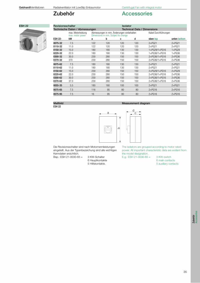
35
Zube
hör
Acce
ssor
ies
a
b
dc
0
GebhardtVentilatoren Radialventilator mit LowSlip Einbaumotor Centrifugal Fan with integral motor
Zubehör Accessories
ESH 22
Die Revisionsschalter sind nach Motornennleistungen eingeteilt. Aus der Typenbezeichung sind alle wichtigen Kenndaten ersichtlich. Bsp.: ESH 21-0030-65 = 3 KW-Schalter 6 Hauptkontakte 5 Hilfskontakte.
The isolators are grouped according to motor rated power. All important characteristic data are evident from the model designation. E.g.: ESH 21-0030-65 = 3 KW-switch 6 main contacts 5 auxiliary contacts
max. Motorleistung Abmessungen in mm, Änderungen vorbehalten Kabel Durchführungen max. motor power Dimensions in mm, Subject to change ESH 22- kW a b c d oben top unten bottom
0075-32 7.5 122 120 120 120 2×PG21 2×PG210110-32 11.0 122 120 120 120 2×PG21 2×PG210150-32 15.0 180 180 130 130 1×PG29/1×PG16 1×PG290220-32 22.0 180 180 130 130 1×PG36/1×PG16 1×PG360300-32 30.0 230 280 150 150 2×PG36/1×PG16 2×PG360370-32 370 230 280 150 150 2×PG36/1×PG16 2×PG36
0075-62 7.5 180 180 130 130 2×PG21 2×PG210110-62 11.0 180 180 130 130 2×PG21 2×PG210150-62 15.0 230 280 150 150 2×PG29/1×PG16 2×PG290220-62 22.0 230 280 150 150 2×PG36/1×PG16 2×PG360300-62 30.0 230 280 150 150 2×PG36/1×PG16 2×PG360370-62 37.0 230 280 150 150 2×PG36/1×PG16 2×PG36
0055-35 5.5 180 180 100 100 2×PG21 2×PG21
0075-65 7.5 116 95 80 80 2×PG16 2×PG16
0075-95 7.5 16 95 80 80 2×PG16 2×PG16
Revisionsschalter IsolatorESH 22Technische Daten / Abmessungen Technical Data / Dimensions
Maßbild Measurement diagram
36
GebhardtVentilatoren Radialventilator mit LowSlip Einbaumotor Centrifugal Fan with integral motor
Beschreibung Description
Die Radialventilatoren rotavent, zweiseitig saugend mit Direktantrieb durch Low slip -Einbaumotoren im Förderstrom sind für den Einsatz in der allgemeinen Luft- und Klimatechnik konzipiert.
Die Ventilatoren in diesem Katalog sind für die Förde-rung von Luft und anderen nicht aggressiven Gasen geeignet. Die zulässigen Fördermediumstemperaturen liegen zwi-schen -30 °C und +40 °C.
Die Hochleistungs-Radial-Ventilatoren Gebhardt rota-vent sind das Ergebnis umfangreicher und systemati-scher Entwicklungsarbeiten. Die Baugrößen sind geometrisch abgestuft nach der Normreihe R 20, und die Nenngröße entspricht dem Laufrad-Außendurchmesser. Die Ventilatoren sind nur mit horizontaler Achse einsetzbar.
The rotavent series of centrifugal fans, with double inlet and low-slip direct drive integral motors in the fan airstream are designed for the use in air handling and ventilation installations.
The fans in this catalogue are suitable for conveying air and other non aggressive gases. The temperatures admitted for the fluid are from -30°C to +40°C.
Gebhardt high-performance rotavent centrifugal fans are the result of extensive and systematic develop-mentwork. The sizes are geometrically reduced in accordance with the standard range R 20 and the nominal size stated is the external diameter of the impeller. The fans may be used only with horizontal shaft.
The fans are designed for installation in equipment and a standard are not equipped with protective guards. They should not be put into operation before all protec-tive devices are fitted and connected! Protective measures must be carried out as set out in DIN EN 292-1, Paragraph 3.22 “Separating Safety Devices” and in DIN EN 292-2, Paragraph 4, “Technical Safety Measures”. If the application of the fan allows free access to the inlet and discharge apertures, safety devices must be put in place on the fan in accordance with DIN EN 294! Suitable safety guards for inlet- and outlet side are avai-lable as an optional extra.
Die Ventilatoren sind für den Geräte- bzw. Anlagenein-bau konzipiert und besitzen standardmäßig keinen eige-nen Berührungsschutz. Sie dürfen erst in Betrieb genommen werden, wenn alle Schutzeinrichtungen angebracht und angeschlossen sind! Die Schutzvorrichtungen müssen entsprechend DIN EN 292-1, Abschnitt 3.22 „Trennende Schutzeinrichtung“ und DIN EN 292-2, Abschnitt 4 „Technische Schutz-maßnahmen“ ausgeführt sein. Sind durch die Einsatzart des Ventilators Eintritts- und Austrittsöffnungen frei zugänglich, müssen Schutzvor-richtungen entsprechend DIN EN 294 am Ventilator an-gebracht werden! Passende, der Norm entsprechende Berührungsschutzgitter für die Eintritts- und Austrittssei-te sind als Zubehör lieferbar.
All fittings and accessory parts for the fans must be ordered separately. Technical data and dimensions can be found in the re-spective sections of the catalogue, the price list or our selection program ProSELECTA++.
Sämtliche Ausstattungen und Zubehörteile für die Venti-latoren müssen separat bestellt werden. Technische Daten und Abmessungen entnehmen Sie bitte den jeweiligen Abschnitten dieses Kataloges, der Preisliste oder unserem Auswahlprogramm ProSELECTA++.
Gebhardt fans are treated with high quality corrosion protection as standard. Depending on the model they are produced from galva-nised sheet steel, lap jointed or welded, degreased, iron phosphated and powder or wet paint coated. Depending on the use of which the fan is to be put and the degree of exposure to corrosion, we offer various anti-corrosion protection measures. More detailed information can be found in the Fittings / accessories section or on the internet under www.geb-hardt.de/documentation/corrosion-protectionsystems.
Gebhardt-Ventilatoren sind serienmäßig mit hochwerti-gem Korrosionsschutz versehen. Sie sind je nach Ausführung im Falzverfahren aus ver-zinktem Stahlblech hergestellt oder in Schweißkonstruk-tion (unterbrochen geschweißt) gefertigt, entfettet, ei-senphosphatiert und pulver- oder nasslackbeschichtet. Abhängig von dem Verwendungszweck und der Kor-rosionsbeanspruchung bieten wir verschiedene Korro-sionsschutzmaßnahmen unterteilt in Korrosionsschutz-klassen an. Genaueres finden Sie im Abschnitt Ausstattung /Zube-hör“ bzw. im Internet unter www.gebhardt.de / Doku-mentationen / Korrosionsschutzsysteme.
Fördermedien Media handled
Schutzeinrichtungen Protective installation
Ausstattung / Zubehör Fittings / Accessories
Korrosionsschutz Corrosion protection
Ausführung Design
37
Besc
hrei
bung
Desc
riptio
n
V400
230
50 87 Hz
GebhardtVentilatoren Radialventilator mit LowSlip Einbaumotor Centrifugal Fan with integral motor
Beschreibung Description
Die speziell entwickelten Low slip- Einbaumotoren sind in Schutzart IP54, Wärmeklasse F ausgeführt. Sie sind auf hohen Wirkungsgrad optimiert und über Frequenz-umrichter drehzahlveränderbar von 0 bis 100%. Die Motoren sind mit einem leicht zugänglichen Metall-Klemmenkasten ausgerüstet. Zum Schutz vor Überlastung sind in die Wicklungen der Motoren Kaltleiter-Temperaturfühler eingefügt. In Verbindung mit einem Kaltleiter-Auslösegerät oder einem Frequenzumrichter mit Kaltleiter-Anschluß wird ein wirksamer Motorschutz gewährleistet. Die Motoren sind werksseitig im Stern (Y) ver-schaltet. Bei Frequenzumrichterbetrieb müssen die Brücken im Dreieck () gelegt werden (siehe Schaltbild).
The specially developed low-slip integral motors are designated as having protection class IP54 and heat class F. They are optimised to a high rate of efficiency, with speed that can be adjusted between 0 and 100% via the frequency inverter. The motors are fitted with an easily accessible metal clamping box. To prevent overloading, PTC are inserted in the win-dings of the motors. In conjunction with PTC release equipment or a frequency inverter with PTC connec-tion, effective motor protection is guaranteed.The motors ex works are in star connection (Y). When operating with a frequency inverter, the links must be placed in delta connection () (see wiring diagram).
The high performance centrifugal impellers have 11 (fan size 0225 up to 0280) or 12 (fan size 0315 up to 0560) backwardcurved blades of true aerofoil shape manufactured from galvanised sheet steel, stewelded, degreased and coated. The impellers with motors are statically and dynamically balanced to G 2.5 (DIN ISO 1940) and fitted to the shaft of the integral motor and with anti-vibration suspension mounted.
Die Hochleistungslaufräder mit 11 rückwärtsgekrüm-mten Schaufeln (Baugröße 0225 bis 0280) bzw. 12 rückwärtsgekrümmten Hohlprofilschaufeln (ab Bau-größe 0315) sind aus Stahlblech gefertigt, geschweißt und pulverbeschichtet. Sie werden statisch und dyna-misch gemeinsam mit dem Motor nach DIN ISO 1940, Gütestufe G 2.5 ausgewuchtet und direkt auf den Rotor des Einbaumotors verschraubt und schwingungsisoliert am Gehäuse befestigt.
Alle Ventilatoren werden anschlussfertig geliefert. Der elektrische Anschluss erfolgt gemäß der beigefügten Betriebsanleitung unter Beachtung der jeweils gültigen örtlichen Vorschriften und Richtlinien. Jedem Ventilator ist ein Anschlussschema beigefügt. Die aktuelle Schaltbild-Zuordnung finden Sie auch onli-ne unter: www.gebhardt.de/Dokumentationen/Schaltbilder.
FrequenzumrichterbetriebEs muss bei einer Nennspannung von 400 V die Eckfrequenz von 87 Hz eingestellt werden. Der Mo-tor ist dann im Dreieck () zu verschalten. Die Ausgabespannung des Frequenzumrichters in Ab-hängigkeit der Frequenz, ist für eine quadratische Span-nungs-Frequenz-Kennlinie im Diagramm abgebildet. Bei direktem Netzbetrieb (400 V) ist der Motor in Stern Schaltung (Y) anzuschließen. Werden bauseits Frequenzumrichter zugeordnet, muss sichergestellt sein, daß die Spannungssteilheit des Frequenzumrichters den Wert von 500 V/µs nicht übersteigt und die maximale Spitzenspannung an den Motorklemmen von 1200 V eingehalten wird. Je nach verwendetem Frequenzumrichter und der Leitungslänge zwischen Frequenzumrichter und Einbaumotor sind Zusatzgeräte (z.B.: Motordrossel, aktiver Sinusfilter) vorzusehen, damit die genannten Grenzwerte eingehal-ten werden. Nichtbeachtung kann zur Zerstörung des Motors führen!
All fans are delivered ready for connection. Electrical connection takes place in accordance with the enc-losed operating instructions and observing the relevant applicable local regulations and directives. Every fan is accompanied by a connection circuit diagram. You can also find the relevant circuit diagram online un-der: www.gebhardt.de/Documentation/wiring diagrams.
Frequency inverter operationFrequency inverter operation with a nominal voltage of 400 V the edge frequency of 87 Hz must be set. The motor must then be delta () connected. The inverter exit voltage is a square function of the frequency and the voltage-frequency-curve has a corre-sponding shape. In the case of direct mains (400 V) operation the motor should be star (Y) connected. If frequency inverters are allocated by the customer, then it must be ensured that the voltage gradient of the frequency inverter does not exceed the figure of 500 V/µs and the maximum peak voltage at the motor ter-minals is kept to 1200 V. Depending on the frequency inverter employed and the length of cable between the frequency inverter and the motor, additional units (such as motor choke, active sinus filter, for example) may be needed to ensure that the limits named above are kept to. Non-compliance may lead to damage to the motor!
Das nicht gasdichte Spiralgehäuse, aus verzinktem Stahlblech gefertigt, ist austrittsseitig für den Anschluss von Flanschen vorbereitet und mit angeschraubten, leicht umsetzbaren Füßen für andere Gehäusestellun-gen versehen.
The scroll casing, which is not gas-tight, is made of galvanised sheet steel and is provided with flange con-nections at the outlet and with bolted on, interchange-able feet for other directions.
Laufräder Impellers
Motor / Moroschutz Motor / Motor protection
elektrischer Anschluss electrical connection
Gehäuse Housing
38
RZA
FU FI IMV
ERA EIP
GebhardtVentilatoren Radialventilator mit LowSlip Einbaumotor Centrifugal Fan with integral motor
Beschreibung Description
Gebhardt bietet mit optimal aufeinander abgestimmten Systemkomponenten die Möglichkeit der wirtschaftli-chen, bedarfsgerechten Regelung der Radialventilatoren RZA.
Gebhardt fans RZA and the system components are specially selected in connection with the requirements of the customer.
The fan curves were produced on a test rig conforming to ISO 5801 (BS 848-1) “Fan Performance Testing, Standardised airways”. The curves show the total pressure rise pt as a func-tion of the volume flow rate V
. plotted logarithmically.
System resistance efficiency curves are then represen-ted by straight lines.The degree of efficiency marked on the constant system lines is only valid at the maximum permis-sible rotational speed of fan nmax.
The increase in static pressure pfa when a duct is at-tached can be calculated from the equation:pfa = pt – pd2
When selecting a fan, attention should be paid to the point that the required duty point has to be situated within the admitted area for the given execution. All data are produced for a reference density of ρ1 = 1,20 kg/m3. The performance data of the touravent fan range are produced conforming to DIN 24 166 “Fans, Technical Delivery Conditions” (equivalent to BS 848, class B) and their accuracy is established according to tolerance class 2.
Die Kennlinien der Ventilatoren werden auf einem saug-seitigen Kammerprüfstand entsprechend DIN 24 163-2 „Ventilatoren, Leistungsmessung, Normprüfstände“ ermittelt. In den Diagrammen aller Baureihen ist die Totaldrucker-höhung pt in Abhängigkeitdes Volumenstromes V
..
in doppelt logarithmischer Netzteilung dargestellt (für druckseitigen Kanalanschluss). Die Drossellinien (Widerstandsparabeln) erscheinen hierbei als Geraden. Der an den Drossellinien angeschriebene Wirkungs-grad gilt für die maximal zulässige Ventilatordreh-zahl nmax.
Die statische Druckerhöhung pfa bei druckseitig ange-schlossenem Kanal kann nach der folgenden Beziehung bestimmt werden:pfa = pt – pd2
Bei der Auswahl des Ventilators ist darauf zu achten, dass der gewünschte Betriebspunkt innerhalb des für diesen Ventilator zulässigen Kennfeldbereiches liegt.Alle Daten gelten für eine Bezugsdichte von ρ1 = 1,20 kg/m3. Die Kenndaten der Radialventilatoren touravent werden entsprechend DIN 24 166 „Ventilatoren, Technische Lie-ferbedingungen“ in Genauigkeitsklasse 2 eingeordnet.
Noise measurements are undertaken in accordance with DIN 45 635-38 “Noise measurements of machines: Fans” (equivalent to BS 848 - 2). The ”A” weighted sound power levels are marked on the fan curves and are valid for both inlet (LWA7) and the discharge (LWA4). An approximation of the ”A” weighted sound pressure LpA7/LpA4 at a distance of 1 m may be obtained by subtracting 7 dB from the indicated ”A” weighted sound power levels. It should be noted that site acoustics, duct design, reverberation, natural frequencies etc. can all influence noise to grater or lesser extent.
Die Geräuschmessung und -auswertung erfolgt nach DIN 45 635-38 „Geräuschmessung an Maschinen; Ventilatoren“. In den Kennfeldern ist als Emissionsgröße der A-Schall-leistungspegel LWA angegeben, der mit gleichem Zah-lenwert für die Eintrittsseite (LWA7) und die Austrittsseite (LWA4) gilt. Den bewerteten Schalldruckpegel LpA7/LpA4 für einen Abstand von einem Meter von der Eintrittsöffnung bzw. Austrittsöffnung erhält man angenähert, indem man vom jeweiligen A-Schallleistungspegel 7dB subtrahiert. Hierbei ist jedoch zu beachten, dass Raumakustik, Kanalanschlüsse, Eigenfrequenzen und Reflexionen das Geräusch an einem bestimmten Ort beeinflussen können.
Die Komponenten • der Ventilator RZA mit
energieoptimiertem Ein-baumotor und Volumen-strom-Messvorrichtung IMV
• der Differenzdrucksen-sor EIP
• das Regelgerät ERA mit K-Faktor Eingabe (optional)
• der Frequenzumformer FU zur bedarfsgerech-ten Ventilatorregelung
The components • the fan RZA with energy
optimised integral motor and volumeter IMV
• the differencial pressure sensor EIP
• the universal measure device ERA with K-factor input (at option)
• the frequency inverter FI for speed regulation
Integrierte Volumenstromregelung
Geräusche Sounds
Leistungsmessung Performance data
39
Besc
hrei
bung
Desc
riptio
n
GebhardtVentilatoren Radialventilator mit LowSlip Einbaumotor Centrifugal Fan with integral motor
Beschreibung Description
Wir behalten uns vor, die in diesem Katalog enthaltenen Abmessungen und technischen Daten im Falle der Wei-terentwicklung unserer Produkte zu ändern. Alle Angaben entsprechen dem Stand bei der Druckle-gung.
DIN EN ISO 9001 Gebhardt Qualität ist das Ergebnis einer konsequent verfolgten geschäftspolitischen Zielsetzung, nach der Gebhardt Produkte Eigenschaften und Merkmale auf-weisen sollen, die eindeutig über dem Durchschnitt ver-gleichbarer Produkte liegen. Diese bereits seit der Unternehmensgründung geltende Maxime führte im April 1985 zu Auditierung und Zertifi-zi-erung des bestehenden Qualitätssicherungssystems. Es wurde in den folgenden Jahren den geänderten in-ternationalen und europäischen Normen angepasst. Moderne Produktionsverfahren, überwacht durch unser Qualitätsmanagementsystem, gewährleisten eine hohe Wiederholgenauigkeit in der Fertigung. Dieser gleich bleibend hohe Qualitätsstandard ermög-licht eine Festlegung der Leistungsdaten in Genauig-keitsklassen nach DIN 24166. Die engen Toleranzen gewährleisten eine hohe Datensi-cherheit für unsere Produkte.
Die Ventilatoren, die dieser Katalog beinhaltet, sind verwendungsfähige Maschinen im Sinne der EG-Ma-schinenrichtlinie. Sie werden mit einem CE-Zeichen gekennzeichnet und mit einer EG-Konformitätserklärung ausgeliefert. Die Beurteilung der vom Ventilator ausgehenden Gefährdungen und notwendiger sicher-heitstechnischer Maßnahmen erfolgte anhand des VDMA-Einheitsblattes 24 167: Ventilatoren; Sicher-heitsanforderungen. In der Betriebsanleitung ist angegeben, welche Sicher-heitsmaßnahmen bauseits noch notwendig sind, damit der Ventilator den Bestimmungen der EG-Maschinen-richtlinie 98/37/EG, mit den Änderungen 91/368/EWG, 93/44/EWG und 93/68/EWG entspricht.
We reserve the right to change any measurements and technical data in this catalogue in accordance with further development of our products. All information corresponded at the time of printing.
DIN EN ISO 9001 Gebhardt quality is the result of an ongoing targeted commercial policy intended to guarantee Gebhardt Pro-ducts properties and features, which are clearly superior to the average comparable products. This already established company maxim led in April 1985 to the auditing and certification. It was in the following years updated to match the changing International and European Standards and on each occasion audited. Modern production methods monitored by our Quality Management System guarantee a high repeat accuracy in production. This ongoing high standard of quality permits the esta-blishing of the performance data in classes of accuracy in accordance with DIN 24 166. The narrow tolerances ensure a high level of data reliability for our products.
Gebhardt rotavent Centrifugal Fans are usable machi-nes in the sense of the EU Guidelines. They are identi-fied with the CE Sign and supplied with an EU Declara-tion of Conformity.An assessment of the dangers associated with the fans and necessary engineering safety measures can be arrived at with the help of the VDMA Unit Sheet 24 167 Fans: Safety requirements. Operating Instructions give which safety measures are still necessary on assembly to ensure that the fans comply with the EU Machine Guideline 98/37/EWG with the Modifications 91/368/EWG, 93/44/EWG and 93/68/EWG.
Qualitätsmanagementsystem Quality Management System DIN EN ISO 9001
Hinweis zur Maschinensicherheit Notes on Machine Safety CE
Hinweis zu Katalogdaten Notes on Catalogue Data

40
D/G
B-R
V3.
3-R
ZA –
0 0
00-0
1.20
06 –
Prin
ted
in G
erm
any
Ihr System-PartnerGebhardtVentilatorenGmbH & Co. KG
Gebhardtstrasse 19-25D 74638 Waldenburg
Telefon +49 (0)7942 101 0Telefax +49 (0)7942 101 170E-Mail [email protected]
www.gebhardt.de
Nutzen Sie ...
... unsere Beratung bereits in der Projektierungsphase
... unser Expertenteam zum aktuellen Stand exakter Informationen über Radialventilatoren
... unser Schulungszentrum zur Einarbeitung in alle Aspekte der Lufttechnik
... unser Labor zur Durchführung von Versuchen
... unsere Software zur schnellen, effektiven Ventilatorenauswahl.
... diese Dokumentation finden Sie online: www.gebhardt.de
Please make use of ...
... our advice at the project planning stage
... our team of experts to get the latest information about centrifugal fans
... our training centre to learn all about air technology
... our laboratory to carry out expe-riments
... our software for the quick, effective selection of fans.
... this documentation is also available through: www.gebhardt.de
rotavent® ist ein Warenzeichen von GebhardtVentilatorenrotavent® is a registered trademark of GebhardtVentilatoren
Related Documents