©W+W 06.2019 Version 2 1 Montageanleitung Mounting instruction Warnhinweis: Anleitung zum späteren Gebrauch vor Ort aufbewahren! ! Die Montage darf nur durch sachkundige Personen* erfolgen. Bei der Montage sind alle entsprechenden Sicherheitsvorschriften und die erforderlichen Sicherheitsmaßnahmen für die Aufzugmontage zu beachten. *sachkundige Person (gem. EN81-20): Person, die entsprechend ausgebildet ist und die auf Kenntnissen und Erfahrungen beruhende Sachkunde besitzt sowie mit den erforderlichen Anweisungen ausgestattet ist, um die geforderten Tätigkeiten zur War- tung oder Prüfung des Aufzugs oder die Befreiung von Benutzern sicher ausführen zu können 601074 Geber-Anbausatz für Kasper KP120/150/155, 130 und 140 Mounting kit with encoder for Kasper KP120/150/155, 130 and 140 ! Vor dem Öffnen des Drucklagers immer das Gegengewicht aufsetzen. Dadurch steht das Getriebe nicht mehr unter Druck. Warning notices: Keep the instructions on site for later use! ! The mounting may be carried out only by specialised persons*. When mounting all corresponding safety regulations and the required safety measures for the mounting of lifts are to be considered. ! Before opening the thrust bearing always put on the counterweight. This way the gear is no longer under pressure. *specialised person (acc. to EN81-20): A person who has been trained accordingly and disposes of expertise based on knowledge and experience, and who is equipped with the necessary instructions to be able to safely effect the required maintenance or control of the lift, or the rescue of passengers

Welcome message from author
This document is posted to help you gain knowledge. Please leave a comment to let me know what you think about it! Share it to your friends and learn new things together.
Transcript

©W+W 06.2019 Version 21
MontageanleitungMounting instruction
Warnhinweis:
Anleitung zum späteren Gebrauch vor Ort aufbewahren!
!Die Montage darf nur durch sachkundige Personen* erfolgen.Bei der Montage sind alle entsprechenden Sicherheitsvorschriften und die erforderlichen Sicherheitsmaßnahmen für die Aufzugmontage zu beachten.
*sachkundige Person (gem. EN81-20):Person, die entsprechend ausgebildet ist und die auf Kenntnissen und Erfahrungen beruhende Sachkunde besitzt sowie mit den erforderlichen Anweisungen ausgestattet ist, um die geforderten Tätigkeiten zur War-tung oder Prüfung des Aufzugs oder die Befreiung von Benutzern sicher ausführen zu können
601074
Geber-Anbausatz für Kasper KP120/150/155, 130 und 140Mounting kit with encoder for Kasper KP120/150/155, 130 and 140
! Vor dem Öffnen des Drucklagers immer das Gegengewicht aufsetzen.Dadurch steht das Getriebe nicht mehr unter Druck.
Warning notices:
Keep the instructions on site for later use!
!The mounting may be carried out only by specialised persons*.When mounting all corresponding safety regulations and the required safety measures for the mounting of lifts are to be considered.
! Before opening the thrust bearing always put on the counterweight.This way the gear is no longer under pressure.
*specialised person (acc. to EN81-20):A person who has been trained accordingly and disposes of expertise based on knowledge and experience, and who is equipped with the necessary instructions to be able to safely effect the required maintenance or control of the lift, or the rescue of passengers

©W+W 06.2019 Version 22
Getriebe-Anbausatz mitGeber für:Lieferumfang
HinweisDie Geberleitung wird anschlussfertig für die neben stehenden Frequenzumrichter geliefert.
Geber mit 10m AnschlussleitungAnbausatz für DrucklagerMontagewerkzeugMontageanleitungKlemmplan für den jeweiligen Umrichter
1.Achtung: Zunächst das Gegengewicht aufsetzen. Dadurch wird eine unbeabsichtigte Drehbewegung des Getriebes verhindert.Mit Hilfe des Montagewerkzeuges den Deckel des Drucklagers öffnen.
Achtung: Es kann etwas Öl austreten.
Montagewerkzeug
1024Imp. 007511 007741 007781
1024Imp.+ Stecker
007512 007742 007782
BIODYN2048Imp.+ Stecker 007513 007743 007783
Unidrive SP/ 300 2048Imp.+ Stecker
007514 007744 007784
1024Imp.+ Stecker
007515 007745 007785
2048Imp.+ Stecker
007516 007746 007786
Goliath 1024Imp. 007517 007747 007787
MFC / CPI1024Imp.+ Stecker
007518 007748 007788
1024Imp. 007519 007749 007789
1024Imp. 007520 007750 007790
VARIODYN VF20/30 2048Imp. 007521 007751 007791
VARIODYN VFxxBR2048Imp.+ Stecker
007522 007752 007792
1024Imp.+ Stecker
007523 007753 007793
1024Imp. 007524 007754 007794
2048Imp. 007525 007755 007795
1024Imp.+ Stecker
007526 007756 007796
UNIVERSAL 4,75-30V, 4 Spuren 1024Imp. 007527 007757 007797
UNIVERSAL 5V, 4 Spuren 2048Imp. 007528 007758 007798
ohne Geber 007529 007759 007799
mit PG Speed control cards
2CF, 3C,3BF, 4C
2CF
4C
Art.Nr.
Impulse proUmdrehung
LCDR
KP120, KP150, KP155
KP130
Art.Nr.
KP140

©W+W 06.2019 Version 23
2.Beide Innensechskantschrauben rausdrehen und die Vierkantmutter abdrehen
3.- Neues Drehteil bis zum Anschlag auf das Gewinde der Welle aufdrehen.- Grundsätzlich ist es ausreichend, wenn das Gewinde des Drehteils zur Hälfte aufgeschraubt ist.- Danach soweit zurück drehen bis die zwei Innensechskantschrauben wieder rein gedreht werden können.- Innensechskantschrauben reindrehen und anziehen.
4.- Zapfenstück bis zum Anschlag in das Gewinde drehen. - Innenliegende Madenschrauben anziehen.

©W+W 06.2019 Version 24
5.- Dichtungsring auf den Flansch des neuen Deckels legen.- Deckel auf das Drucklager schrauben.- Mit Hilfe des Montagewerkzeuges den Deckel anziehen.
6.- Drehmomentstütze (Blechwinkel) an den Inkrementalgeber schrauben.- Geberwelle in die Buchse des Zapfenstückes schieben.- Madenschraube anziehen.- Drehmomentstütze an den Dämpfungsgummi anschrauben.
Drehmomentstütze Madenschraube
- Sollte das Zapfenstück nicht weit genug aus dem Deckel ragen, kann das Dehrteil und somit auch das Zapfenstück etwas zurückgeschraubt werden (siehe Punkt 3).

©W+W 06.2019 Version 25
Gear mounting kits withencoder for:Scope of delivery
IndicationThe encoder cable is supplied ready for con-nection for the frequency converters listed on the right.
Encoder with 10m connecting cableMounting kit for thrust bearingsMounting toolMounting instructionClamping plan for the corresponding converter
1.Attention: At first put on the counterweight. Thereby an unintentional rotation of the gear is prevented.Open the cover of the thrust bearing by means of the mounting tool.
Attention: Some oil may leak out.
Mounting tool
1024pulses 007511 007741 007781
1024pulses+ plug
007512 007742 007782
BIODYN2048Ipulses
+ plug 007513 007743 007783
Unidrive SP/ 300 2048Imp.+ plug
007514 007744 007784
1024pulses+ plug
007515 007745 007785
2048pulses+ plug
007516 007746 007786
Goliath 1024pulses 007517 007747 007787
MFC / CPI1024pulses
+ plug007518 007748 007788
1024pulses 007519 007749 007789
1024pulses 007520 007750 007790
VARIODYN VF20/30 2048pulses 007521 007751 007791
VARIODYN VFxxBR2048pulses
+ plug007522 007752 007792
1024pulses+ plug
007523 007753 007793
1024pulses 007524 007754 007794
2048pulses 007525 007755 007795
1024pulses+ plug
007526 007756 007796
UNIVERSAL 4,75-30V, 4 tracks 1024pulses 007527 007757 007797
UNIVERSAL 5V, 4 tracks 2048pulses 007528 007758 007798
without encoder 007529 007759 007799
with PG Speed control cards
2CF, 3C,3BF, 4C
2CF
4C
Art.no.
Pulses perrevolution
LCDR
KP120, KP150, KP155
KP130
Art.no.
KP140
Art.no.

©W+W 06.2019 Version 26
2.Unscrew both hexagon socket screws and then the square nut.
3.- Screw the new turning element as far as possible onto the thread of the shaft.- Then turn it back a little bit until the two hexagon socket screws can be screwed in again.- Screw the hexagon socket screws in and tighten them.
4.- Turn the adaptor piece as far as possible into the thread. - Tighten the internal grub screws.
©W+W 06.2019 Version 27
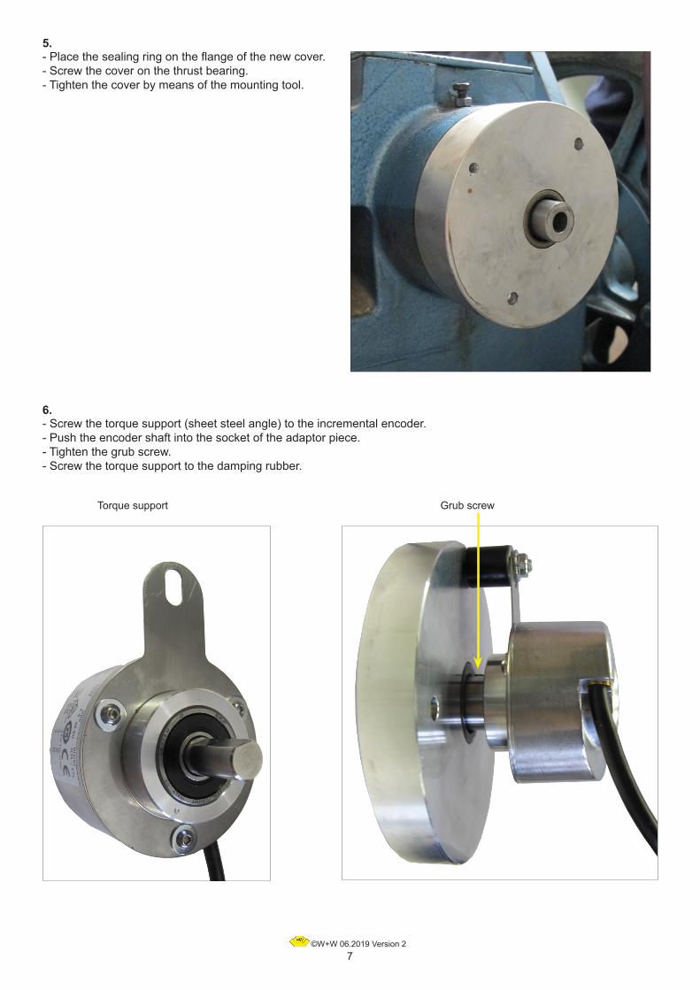
5.- Place the sealing ring on the flange of the new cover.- Screw the cover on the thrust bearing.- Tighten the cover by means of the mounting tool.
6.- Screw the torque support (sheet steel angle) to the incremental encoder.- Push the encoder shaft into the socket of the adaptor piece.- Tighten the grub screw.- Screw the torque support to the damping rubber.
Torque support Grub screw

©W+W 06.2019 Version 28
AnschlussplanConnection diagram
Inkrementalgeber mit 1024 und 2048 Impulsen zur Ansteuerung von Frequenzumrichtern
Incremental encoder with 1024 and 2048 pulsesfor frequency converter controlling
Wenn das Anschlusskabel umrichterseitig ohne Stecker bestellt wurde, ist die Belegung wie folgt:If the supply line was ordered without plug on the side of the frequency converter, the configuration is as follows: + braun / grün brown / green
0V weiß / grün white / green
A braun brown
B grau grey_A grün green _B rosa pink
Wichtig! Werden nur zwei Spuren benötigt, sind die Anschlüsse der anderen beiden Spuren separat zu isolieren und nicht aufzulegen.Important! If only two tracks are needed, the connections of the other two tracks are to be isolatedseparately and not connected.
Encoder 1024 Impulse / pulses:Betriebsspannung / Operating voltage: 4.75 ... 30V DC (TTL/HTL universal)Ausgangsspannung / Output voltage: = Betriebsspannung* / = Operating voltage*Leerlaufstrom / No-load supply current: max. 55mAAusgangstyp / Output type: Gegentakt inkremental / push-pull, incremental *RS422-Funktionalität (TTL) bei 5V-Betrieb / RS422 functionality at 5V operation
Encoder 2048 Impulse / pulses:Betriebsspannung / Operating voltage: 5V DC Ausgangsspannung / Output voltage: 5V DC (TTL / RS422)Leerlaufstrom / No-load supply current: max. 60mAAusgangstyp / Output type: Gegentakt inkremental / push-pull, incremental

©W+W 06.2019 Version 29
Inkrementalgeberanschlüsse / Incremental encoder connectionsAchten Sie darauf, daß Ihr Frequenzumrichter auf den nachfolgenden Gebertyp eingestellt ist bzw. daß die Steckbrücken (gültig nur für einige Umrichtertypen) richtig eingelegt sind.Please make sure that your frequency converter is adjusted to the following type of encoders, respectively that the link plugs (this applies only for some types of converters) are inserted correctly.
DIETZ / emotron DSV 1024 Imp. TTL 5V mit D-SUB dreireihig / with D-SUB three rows
Buchse Umrichter / converter socket PIN 1 PIN 2 PIN 3 PIN 4 PIN 5 PIN 6Farbe Geberkabel
Colour of encoder cablebraunbrown
grüngreen
braun/ grünbrown/green
weiß/ grünwhite/ green
graugrey
rosapink
Geberbezeichnung / name on the encoder A A inv. 4,75-30V 0V B B inv.Ist der Frequenzumrichter voreingestellt auf Sinusgeber, muss der Jumper 3 (Dietz-Anleitung S.19) auf Inkrementalgeber und die JP3-Flag von 0E3E auf 255 umgestellt werden.
If the frequency converter is pre-adjusted to sinus encoders, the Jumper 3 (Dietz instructions p.19) has to be adapted to incremental encoders and the JP3-Flag from 0E3E to 255.
KEB 2048 Imp. TTL 5V mit D-SUB dreireihig / with D-SUB three rows
Buchse Umrichter / converter socket PIN 3 PIN 4 PIN 8 PIN 9 PIN 12 PIN 13Farbe Geberkabel
Colour of encoder cablegrün
greenrosapink
braunbrown
graugrey
braun/ grünbrown/green
weiß/ grünwhite/ green
Geberbezeichnung / name on the encoder A inv. B inv. A B 5V 0V
ASCENTRONIC VKC / VKV / VFV 1024 Imp. HTL10-30V
Klemme Umrichter / converter terminal 41 42 44 40 44 40 45Farbe Geberkabel
Colour of encoder cablebraun/ grünbrown/green
weiß/ grünwhite/ green
graugrey
braunbrown
rosapink
grüngreen
Schirmshielding
Geberbezeichnung / name on the encoder 4,75-30V 0V B A B inv. A inv.
RST 1024 Imp. HTL10-30V
Klemme Umrichter / converter terminal 27 28 31 66Farbe Geberkabel
Colour of encoder cablebraunbrown
graugrey
braun/ grünbrown/green
weiß/ grünwhite/ green
Geberbezeichnung / name on the encoder A B 4,75-30V 0VDie Kabelabschirmung muss an einer PE-Klemme am Umrichter aufgelegt werden. The cable shielding has to be connected at a PE-terminal at the converter.
Nu
r
fü
r
As
yn
ch
ro
nm
ot
or
en
!
/
On
ly
f
or
a
sy
nc
hr
on
ou
s
mo
to
rs
!
KW Goliath-60 / -90 1024 Imp. HTL10-30V
Klemme Umrichter / converter terminal 20 21 22 23 25 Goliath-60Klemme Umrichter / converter terminal 40 41 42 46 45 Goliath-90
Farbe GeberkabelColour of encoder cable
Schirmshielding
braunbrown
graugrey
braun/ grünbrown/green
weiß/ grünwhite/ green
Geberbezeichnung / name on the encoder A B 4,75-30V 0V
OMRON + PG Speed Control Cards 1024 Imp. HTL10-30V
Klemme Umrichter / converter terminal 1 2+6 3+4 5 TA2(E) PPGA2Farbe Geberkabel
Colour of encoder cablebraun/ grünbrown/green
weiß/ grünwhite/ green
Brückelink
braunbrown
Schirmshielding
Geberbezeichnung / name on the encoder 4,75-30V 0V A
Brunner & Fecher 1024 Imp. TTL 5V mit D-SUB zweireihig / with D-SUB two rows
Buchse Umrichter / converter socket PIN 1 PIN 2 PIN 4 PIN 5+9 PIN 6 PIN 7Farbe Geberkabel
Colour of encoder cablebraunbrown
graugrey
braun/ grünbrown/green
weiß/ grünwhite/ green
grüngreen
rosapink
Geberbezeichnung / name on the encoder A B 4,75-30V 0V A inv. B inv.
Biodyn 2048 Imp. TTL 5V mit WECO-Stecker / with WECO plug
Buchse Umrichter / converter socketFarbe Geberkabel
Colour of encoder cablebraun/ grünbrown/green
weiß/ grünwhite/ green
braunbrown
grüngreen
graugrey
rosapink
Geberbezeichnung / name on the encoder 5V 0V A A inv. B B inv.
UNIDRIVE SP / E300 1024 Imp. HTL10-30V mit D-SUB dreireihig / with D-SUB three rows
Buchse Umrichter / converter socket PIN 1 PIN 2 PIN 3 PIN 4 PIN 13 PIN 14Farbe Geberkabel
Colour of encoder cablebraunbrown
grüngreen
graugrey
rosapink
braun/ grünbrown/green
weiß/ grünwhite/ green
Geberbezeichnung / name on the encoder A A inv. B B inv. 4,75-30V 0V+ Schirm / + shielding
LiftEquip MFC und CPI 1024 Imp. TTL 5V mit D-SUB zweireihig / with D-SUB two rows
Buchse Umrichter / converter socket PIN 1 PIN 2 PIN 3 PIN 4 PIN 7 PIN 9Farbe Geberkabel
Colour of encoder cablegrün
greenbraunbrown
graugrey
rosapink
weiß/ grünwhite/ green
braun/ grünbrown/green
Geberbezeichnung / name on the encoder A inv. A B B inv. 0V 4,75-30VSteckergehäuse ist mit Kabelschirm verbunden. / The connector housing is connected to the cable shield.
©W+W 06.2019 Version 210
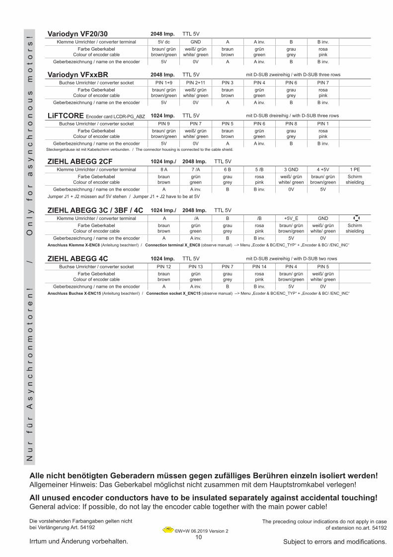
All unused encoder conductors have to be insulated separately against accidental touching!General advice: If possible, do not lay the encoder cable together with the main power cable!
The preceding colour indications do not apply in case of extension no.art. 54192
Subject to errors and modifications.
Variodyn VFxxBR 2048 Imp. TTL 5V mit D-SUB zweireihig / with D-SUB three rows
Buchse Umrichter / converter socket PIN 1+9 PIN 2+11 PIN 3 PIN 4 PIN 6 PIN 7Farbe Geberkabel
Colour of encoder cablebraun/ grünbrown/green
weiß/ grünwhite/ green
braunbrown
grüngreen
graugrey
rosapink
Geberbezeichnung / name on the encoder 5V 0V A A inv. B B inv.
Alle nicht benötigten Geberadern müssen gegen zufälliges Berühren einzeln isoliert werden!Allgemeiner Hinweis: Das Geberkabel möglichst nicht zusammen mit dem Hauptstromkabel verlegen!
Die vorstehenden Farbangaben gelten nicht bei Verlängerung Art. 54192
Irrtum und Änderung vorbehalten.
Variodyn VF20/30 2048 Imp. TTL 5VKlemme Umrichter / converter terminal 5V dc GND A A inv. B B inv.
Farbe GeberkabelColour of encoder cable
braun/ grünbrown/green
weiß/ grünwhite/ green
braunbrown
grüngreen
graugrey
rosapink
Geberbezeichnung / name on the encoder 5V 0V A A inv. B B inv.
ZIEHL ABEGG 2CF 1024 Imp./ 2048 Imp. TTL 5VKlemme Umrichter / converter terminal 8 A 7 /A 6 B 5 /B 3 GND 4 +5V 1 PE
Farbe GeberkabelColour of encoder cable
braunbrown
grüngreen
graugrey
rosapink
weiß/ grünwhite/ green
braun/ grünbrown/green
Schirmshielding
Geberbezeichnung / name on the encoder A A inv. B B inv. 0V 5VJumper J1 + J2 müssen auf 5V stehen / Jumper J1 + J2 have to be at 5V
ZIEHL ABEGG 3C / 3BF / 4C 1024 Imp./ 2048 Imp. TTL 5VKlemme Umrichter / converter terminal A /A B /B +5V_E GND
Farbe GeberkabelColour of encoder cable
braunbrown
grüngreen
graugrey
rosapink
braun/ grünbrown/green
weiß/ grünwhite/ green
Schirmshielding
Geberbezeichnung / name on the encoder A A inv. B B inv. 5V 0VAnschluss Klemme X-ENC8 (Anleitung beachten!) / Connection terminal X_ENC8 (observe manual) --> Menu „Ecoder & BC/ENC_TYP“ + „Encoder & BC/ /ENC_INC“
Nu
r
fü
r A
sy
nc
hr
on
mo
to
re
n!
/
O
nly
f
or
a
sy
nc
hr
on
ou
s
mo
to
rs
!
ZIEHL ABEGG 4C 1024 Imp. TTL 5V mit D-SUB zweireihig / with D-SUB two rows
Buchse Umrichter / converter socket PIN 12 PIN 13 PIN 7 PIN 14 PIN 4 PIN 5Farbe Geberkabel
Colour of encoder cablebraunbrown
grüngreen
graugrey
rosapink
braun/ grünbrown/green
weiß/ grünwhite/ green
Geberbezeichnung / name on the encoder A A inv. B B inv. 5V 0VAnschluss Buchse X-ENC15 (Anleitung beachten!) / Connection socket X_ENC15 (observe manual) --> Menu „Ecoder & BC/ENC_TYP“ + „Encoder & BC/ /ENC_INC“
LiFTCORE Encoder card LCDR-PG_ABZ 1024 Imp. TTL 5V mit D-SUB dreireihig / with D-SUB three rows
Buchse Umrichter / converter socket PIN 9 PIN 7 PIN 5 PIN 6 PIN 8 PIN 1Farbe Geberkabel
Colour of encoder cablebraun/ grünbrown/green
weiß/ grünwhite/ green
braunbrown
grüngreen
graugrey
rosapink
Geberbezeichnung / name on the encoder 5V 0V A A inv. B B inv.Steckergehäuse ist mit Kabelschirm verbunden. / The connector housing is connected to the cable shield.
Related Documents


![Kasper Munk [Português]](https://static.cupdf.com/doc/110x72/58cfcb341a28ab7c6e8b588b/kasper-munk-portugues.jpg)